Data Center Infrastructure Resource Guide - comsol.gr · Anixter is the world’s leading supplier...
64
Data Center Infrastructure Resource Guide
-
Upload
nguyenquynh -
Category
Documents
-
view
218 -
download
2
Transcript of Data Center Infrastructure Resource Guide - comsol.gr · Anixter is the world’s leading supplier...

7H00
03Z1
©20
08An
ixter
Inc.•
02/0
8•10
K•25
1984
Enterprise Cabling & Security Solutions • Electrical and Electronic Wire & Cable • Fasteners • Supply Chain ServicesAnixter Inc. • 1.800.ANIXTER • anixter.com
World Headquarters: 2301 Patriot Boulevard, Glenview, IL 60026-8020 • 224.521.8000
Anixter Inc. is a leading global supplier of Supply Chain Services and products used to connect voice, video, data and security systems. Anixter is also a leading provider of specialty electrical and electronic wire and cable for building construction, industrial maintenance and repair, and original equipment
manufacturing, as well as a leader in providing fasteners and “C” Class components to OEMs and production lines. We bundle our products with our innovative Supply Chain Services to help control the cost of our customers’ business processes, reduce their investment in inventory, and ensure they get the right product when they need it. A NYSE listed company, Anixter, with its subsidiaries, serves companies in more than 49 countries around the world.
Anixter’s total revenue exceeds $5.8 billion.
Anixter Inc. does not manufacture the items described in this publication. All applicable warranties are provided by the manufacturers. Purchasers are requested to determine directlyfrom the manufacturers the applicable product warranties and limitations. Data and suggestions made in the publication are not to be construed as recommendations or authorizations
to use any products in violation of any government law or regulation relating to any material or its use.
DataCenterInfrastructure
ResourceGuide
Data CenterInfrastructure Resource Guide

Anixter is the world’s leading supplier of communications products used to connect voice, video, data and security systems. Anixter is also the leading provider of electrical and electronic wire and cable, fasteners, and other small components to build, repair,and maintain a variety of systems and equipment. We bundle our products with our innovative Supply Chain Services to cut costs out of our customers’ business processes, and ensure they get the right product, the first time.
MexicoCiudad JuarezGuadalajaraMexico CityMonterrey
PanamaPanama City
PeruLima
Puerto RicoSan Juan
VenezuelaCaracas
Europe/MiddleEast/AfricaEuropean HQUxbridge, England44-1895-818181
United KingdomAberdeenBelfastBirminghamGlasgowUxbridgeWarrington
AustriaVienna
BelgiumWillebroek
Czech RepublicPrague
DenmarkCopenhagen
FinlandHelsinki
FranceParis
GermanyKorntal-Münchingen
GreeceAthens
HungaryBudapest
IrelandDublin
ItalyMilanRome
NetherlandsLE Capelle aan den IJssel
NorwayOslo
PolandWarsaw
PortugalLisbon
RussiaMoscow
SlovakiaBratislava
SpainBarcelonaMadrid
SwedenGothenburgStockholm
SwitzerlandMontreuxZurich
TurkeyIstanbul
United Arab EmiratesDubai
Asia/PacificAsia/Pacific HQSingapore+65-6756-7011
South Pacific HQSydney, Australia612-9-333-0800Australia
BrisbaneMelbourneSydney
ChinaShanghai
Hong KongIndia
BangaloreChennaiMumbaiNew Dehli
IndonesiaJakarta
JapanMalaysia
Kuala LumpurPenang
New ZealandAuckland
PhilippinesManila
SingaporeSingapore
TaiwanTaipei
ThailandBangkok
Vietnam
International ServicesGlenview, IL224-521-8000After HoursUSA800-323-8167Canada800-361-0250

Table of Contents
SECTION 4 – BEST PRACTICES FOR DATA CENTERS — DATA CENTER STANDARDS AND ASSOCIATIONS
ANSI/TIA/EIA-942 (Data Center) . . . . . . . . . . . . . . . . . . . . . . . . . .30Data Center Topology . . . . . . . . . . . . . . . . . . . . . . . . . . . . . . . . . .32Hot and Cold Equipment Aisles . . . . . . . . . . . . . . . . . . . . . . . . . . .34Data Center Infrastructure Tiers . . . . . . . . . . . . . . . . . . . . . . . . . .35Uptime Institute Tiers . . . . . . . . . . . . . . . . . . . . . . . . . . . . . . . . . .36Protection of Data Center Assets . . . . . . . . . . . . . . . . . . . . . . . . .38IEEE 802.3an (10GBASE-T Task Force) . . . . . . . . . . . . . . . . . . . . . .39ANSI/TIA-568-B.2-1(ADIO) and ISO 11801 Class EA . . . . . . . . . . . .39IEEE 802.3af and 802.3at (PoE) . . . . . . . . . . . . . . . . . . . . . . . . . .39ANSI/TIA/EIA-569-B (Pathways and Spaces) . . . . . . . . . . . . . . . . .40ANSI/TIA/EIA-606-A (Administration) . . . . . . . . . . . . . . . . . . . . . .40J-STD-607-A-2002 (Grounding and Bonding) . . . . . . . . . . . . . . . .40Standards and Power Cables . . . . . . . . . . . . . . . . . . . . . . . . . . . .41Data Center Associations . . . . . . . . . . . . . . . . . . . . . . . . . . . . . . .42“Green” Data Centers and Buildings . . . . . . . . . . . . . . . . . . . . . . .43LEED . . . . . . . . . . . . . . . . . . . . . . . . . . . . . . . . . . . . . . . . . . . . . .43
SECTION 5 – KEY CONSIDERATIONS FOR DEPLOYING DATA CENTER SOLUTIONS
Supply Chain Services and Data Centers . . . . . . . . . . . . . . . . . . . .46Anixter’s Supply Chain Services in Action . . . . . . . . . . . . . . . . . . .50Material Management Matters . . . . . . . . . . . . . . . . . . . . . . . . . . .51
APPENDIX – ABOUT ANIXTER
The Anixter Difference . . . . . . . . . . . . . . . . . . . . . . . . . . . . . . . . .53Our Products . . . . . . . . . . . . . . . . . . . . . . . . . . . . . . . . . . . . . . . .53Our Supply Chain Services . . . . . . . . . . . . . . . . . . . . . . . . . . . . . .54Our Technical Expertise . . . . . . . . . . . . . . . . . . . . . . . . . . . . . . . .55The Anixter Infrastructure Solutions Lab . . . . . . . . . . . . . . . . . . . .55Anixter University . . . . . . . . . . . . . . . . . . . . . . . . . . . . . . . . . . . . .58
SECTION 1 – INTRODUCTION TO DATA CENTERS
What is a Data Center? . . . . . . . . . . . . . . . . . . . . . . . . . . . . . . . .2Types of Data Centers . . . . . . . . . . . . . . . . . . . . . . . . . . . . . . . . .3Common Attributes of Data Centers . . . . . . . . . . . . . . . . . . . . . . .4
SECTION 2 – DATA CENTER DESIGN CONSIDERATIONS
Professional Engineering . . . . . . . . . . . . . . . . . . . . . . . . . . . . . . .6Power Requirements . . . . . . . . . . . . . . . . . . . . . . . . . . . . . . . . . .6Cooling . . . . . . . . . . . . . . . . . . . . . . . . . . . . . . . . . . . . . . . . . . . .8Space Allocation . . . . . . . . . . . . . . . . . . . . . . . . . . . . . . . . . . . . .9Cable Management . . . . . . . . . . . . . . . . . . . . . . . . . . . . . . . . . . .9Access Floors . . . . . . . . . . . . . . . . . . . . . . . . . . . . . . . . . . . . . . . .10
SECTION 3 – DATA CENTER INFRASTRUCTURE CONSIDERATIONS
Racks, Cabinets and Support Infrastructure . . . . . . . . . . . . . . . . . 12Redundancy and Path Diversity . . . . . . . . . . . . . . . . . . . . . . . . . . 12Security . . . . . . . . . . . . . . . . . . . . . . . . . . . . . . . . . . . . . . . . . . . . 13Storage . . . . . . . . . . . . . . . . . . . . . . . . . . . . . . . . . . . . . . . . . . . . 13Flexible and Adequate Connectivity . . . . . . . . . . . . . . . . . . . . . . . 13Choosing the Appropriate Cabling Media . . . . . . . . . . . . . . . . . . . 13Data Center Cabling Considerations . . . . . . . . . . . . . . . . . . . . . . . 14Copper vs. Fiber Cable and Connectivity . . . . . . . . . . . . . . . . . . . . 15The Case for Fiber . . . . . . . . . . . . . . . . . . . . . . . . . . . . . . . . . . . . 16Fiber Use in the Data Center . . . . . . . . . . . . . . . . . . . . . . . . . . . . 16Benefits of Preterminated Fiber Solutions. . . . . . . . . . . . . . . . . . . 1850- vs. 62.5-micron Fiber . . . . . . . . . . . . . . . . . . . . . . . . . . . . . . 18Copper Media and the 21st Century Data Center . . . . . . . . . . . . . 19Types of Copper Cable Construction . . . . . . . . . . . . . . . . . . . . . . . 20Limited Combustible Cable. . . . . . . . . . . . . . . . . . . . . . . . . . . . . . 20Power Cables and Accessories . . . . . . . . . . . . . . . . . . . . . . . . . . . 21Electronic Power System Considerations. . . . . . . . . . . . . . . . . . . . 23Energy Efficiency and Environmental Considerations. . . . . . . . . . . 23Intelligent Infrastructure Management (IIM) . . . . . . . . . . . . . . . . . 24KVM Switches . . . . . . . . . . . . . . . . . . . . . . . . . . . . . . . . . . . . . . . 26

2 |
|Section 1 - Introduction to Data Centers
INTRODUCTION
What is a Data Center?
Data centers are the “nerve centers” of the new economy or special environments that house the latest advances in computer processing and business innovation. Data centers centralize and consolidateInformation Technology (IT) resources, enabling organizations to conduct business around-the-clockand around the world.

|3
Section 1 - Introduction to Data Centers|
A data center is a “hardened” facility that is dedicated to providing uninterrupted service to business-critical data processing operations. Among its many features are:
• 7 x 24 x 365 availability
• Fail-safe reliability and continuous monitoring
• Power management and network communications, redundancy and path diversity
• Network security, physical access control and video surveillance
• Zoned environmental control
• Fire suppression and early warning smoke detection systems.
TYPES OF DATA CENTERS
Data centers fall into two major categories including corporate data centers (CDCs) and Internet data centers (IDCs).
Corporate data centers are owned and operated by private corporations, institutions or government agencies. Their prime purpose includes supporting data processing and Web-oriented services for theirown organizations, business partners and customers. Equipment, applications, support and maintenance for the data center are typically supported by in-houseIT departments or contract partners.
Internet data centers are primarily owned and operatedby traditional telcos, unregulated competitive serviceproviders or other types of commercial operators. Eachoperator, however, involves similar goals—to provideoutsourced Information Technology (IT) servicesaccessed through Internet connectivity. Their businessis to provide a menu of services to their clients. Theseservices may include (but are not limited to) wide-areacommunications, Internet access, Web or applicationhosting, colocation, managed servers, storage networks,content distribution and load sharing with new variationsappearing almost daily.
In many ways, IDCs present an alternate model for Internet connectivity and eCommerce. IDCs are particularlyattractive to new or small-to-medium businesses thathave yet to invest money in IT or simply want to pay for what they use.
THE RECENT SURGE IN DATA CENTER ACTIVITY
The emergence of the Internet as a universal network,the Internet Protocol (IP) as a common computer “communication standard” and the continued advancements and maturity of Web technology haveserved as catalysts for a number of common businessinitiatives. These initiatives include:
• Server consolidation and centralization of processing capability
• Business system continuity and disaster recovery
• Database content and storage management
• “Webification” of business applications
• Information distribution via Intranet and Extranet
• eBusiness and Electronic Data Interexchange (EDI)
• Supply Chain Management (SCM) and Enterprise Resource Planning (ERP)
• Customer Relationship Management (CRM)
• Sales Force Automation (SFA)
• Wireless applications and connectivity.
Another factor contributing to the surge of data centerconstruction is the increase in the number of Internetconnected devices per business or household. Oftentimes, data centers are expanding well beyond thenumber of actual users. Business professionals areadopting wireless PDAs (Personal Digital Assistants) in addition to or within their cell phones. Residentialcustomers often have multiple PCs, wireless networks and a growing comfort factor with the Web as a shopping mall, Yellow Pages and eLibrary. Consequently, a “many-to-one” device-to-user ratio isdriving the need for additional network connectivityand data center expansion.

4 |
|Section 1 - Introduction to Data Centers
Additionally, bandwidth capacity and availability are increasing while monthly access charges aredecreasing for wide area, metropolitan and residentialservices. Web resources must also increase in order to meet the market demand for higher performanceand availability.
CDCs are also expanding and modernizing to meet the growing demands of mobile professionals, as wellas supporting rapid new customer acquisition andenhanced service initiatives. IDCs continue to sproutup around the world to capture market share in theonline business and consumer service market.
SAME ISSUES, DIFFERENT SCALE
Corporate data centers and Internet data centersshare many common attributes and vary mostly interms of scale and user base served. Most corporatedata centers provide connectivity, application servicesand support to hundreds (or thousands) of workerswithin a building, campus or remote company facility.Internet data centers are like 21st century commercialversions of a telco central office. Instead of merelyproviding dial tone, these IPCOs (IP Central Offices) provide IP services over which customers may opt to run voice and video along with their data. The IDC model employs the Internet as an international “network of networks,” traversing many, if not all, traditional telco service areas. The challenge is to provide users with the reliability and performance they have come to expect from their traditional voice providers.
IDCs will continue to implement greater levels ofredundancy and diversity of data paths, includingpower, transport, cabling infrastructure and networkinghardware. Because IDC business plans revolve aroundeconomies of scale, the more services sold per squarefoot of real estate causes density to reign. This often leads to unique issues not always found in the privatedata center environment.
COMMON ATTRIBUTES OF DATA CENTERS
There are many common functions in data centerstoday—whether they are owned and operated by corporations or leased from an Internet data centeroperator. For the most part, all data centers require:
• Internet access and wide area communications
• Application hosting
• Content distribution
• File storage and backup
• Database management
• Failsafe power
• Adequate heating, ventilation and air conditioning(HVAC) and fire suppression
• High-performance cabling infrastructure
• Security (access control, video surveillance, etc.)

|5
Section 2 - Data Center Design Considerations|
SECTION 2 Data Center Design Considerations
Professional Engineering 6
Power Requirements 6
Cooling 8
Space Allocation 9
Cable Management 9
Access Floors 10

6 |
|Section 2 - Data Center Design Considerations
PROFESSIONAL ENGINEERING
With so many electrical, mechanical and communicationvariables involved, successful data center design and construction begins with professional engineering.Data centers are unique environments; developers canbenefit from the architect, engineering and consultingcommunity, along with construction firms with experience in designing and building data centers.
Some of the benefits provided by professional engineering include:
• Familiarity with the trades involved in a project(HVAC, electrical and mechanical)
• Coordination of the many trades involved in the building process
• Telecom and datacom expertise
• Unbiased written specifications based on performance
• Understanding clients’ network demands
• Meeting state licensing requirements
• Assuming professional liability for design and operational problems.
Once data centers are up and running, they have zero tolerance for downtime and other problemscaused by poor design or flawed installations. Careful thought and consideration must be put in the data center design phase.
POWER REQUIREMENTS
As recent as five years ago, planners could rely ontried and true rules of thumb to plan for an adequateamount of power for a data center build-out. However,the staggering pace of technological advancements(especially with servers, switches and storage devices)have combined to completely change the landscape fordata center power consumption. As an example, duringthe five years between 1998 and 2003, data centerpower consumption doubled in the U.S. Even moreremarkable is that this consumption doubled again inthe three years between 2003 and 2006 as reportedby the U.S. Department of Energy. Since 2003, theincreasing acceptance and deployment of blade and 1U (single rack unit) servers are resulting in apower consumption density at the cabinet level thatdrastically changes the traditional rules of thumbdesigners relied on for more than 15 years. Today, the pace of power consumption continues to rapidlyincrease in data centers. As a result, in late 2006, the House and Senate passed bills that tasked theEnvironmental Protection Agency with how to reducethe pace of power consumption in data centers.
Along with power consumption, data centers are also expected to operate without downtime. One of the ways to help data center managers achieve their company’s availability objectives is to design redundancy into the data center infrastructure. As the demand to be operational increases, often it is necessary to duplicate components that make up the data center infrastructure, either to allow forplanned maintenance or to protect availability fromunplanned failures. At the upper end of availabilityrequirements, multiple power grids are funneled into a single data center to provide assurance that therewill always be power available to run the facility.
Thanks to the efforts of the Uptime Institute and other standards resources, most active componentmanufacturers today build their components with
Internet data centers have additionalrequirements that are not always as critical in a private environment or may simply be implemented in a different way.Requirements for cooling and spacingmay differ by data center design.
|7
Section 2 - Data Center Design Considerations|
dual (sometime triple) power supplies. Multiple powersupplies allow a component to have power delivered to it from multiple power sources and pathways.
In conjunction with the increasing amount of power in data centers, it is also becoming more critical tobuild a solid electrical grounding grid to protect theequipment and the personnel. See ANSI/-J-STD-607-A or CENELEC EN50310 for more information.
While the traditional rule of thumb for data centerpower planning has typically been expressed in “wattsper square foot,” availability conscious data centersare adopting “watts per cabinet” as their new rule ofthumb for power planning. In addition, as data centermanagers migrate toward either Tier 3 or Tier 4 availability (as referenced by the Uptime Institute, see page 36), they are constantly looking at ways tocreate redundancy in their infrastructure. This is especially true of data centers that are required tooperate all day, every day. Without redundancy, datacenters would have to shut down the systems to perform routine maintenance.
Even though redundancy in the infrastructure allowscontinuous operation of the data center, it creates significant problems at the cabinet level. Redundantpower supplies require twice as many power cablesand power strip outlets. Multiple communication pathways increase the number of data cables outsideof the cabinet.
In addition, as the power and thermal densitiesincrease at the cabinet level, it is increasingly important that management and monitoring systemsare added to the cabinet and the data center. The systems that are available today provide complete coverage of the environmental and component operation at the cabinet level, as well as for the entire data center. Typical systems can be configuredto monitor temperature, smoke and humidity, as wellas power consumption, fan status and UPS operation.Many of the latest systems also offer access controland video surveillance options. (This topic will be covered in greater detail in Section 3.)
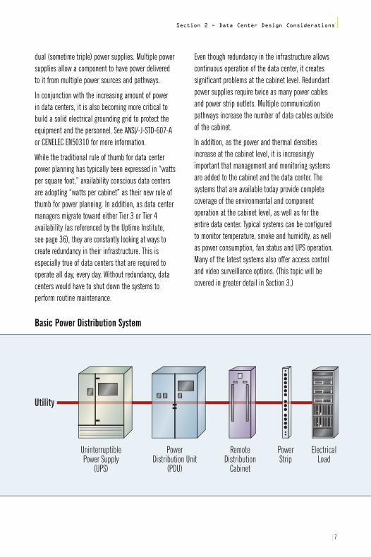
Utility
UninterruptiblePower Supply
(UPS)
PowerDistribution Unit
(PDU)
RemoteDistribution
Cabinet
PowerStrip
ElectricalLoad
Basic Power Distribution System

8 |
|Section 2 - Data Center Design Considerations
COOLING
The steady increase in acceptance of blade and 1U servers has created a significant challenge to provide adequate cooling for high-density equipmentcabinets. In addition, cabinet manufacturers haverecently introduced cabinet designs that address cable management and heat dissipation. Today, it isnot uncommon for a full cabinet of blade servers toconsume over 20 kW of power and to produce over 20 kW of heat.
Along with the new thermally sensitive cabinet designs,there is also a great deal of product development workbeing done to enhance the cooling capabilities of newand existing data center air conditioning systems.
As recommended by the American Society of Heating,Refrigerating and Air-Conditioning Engineers (ASHRAE)and the ANSI/TIA/EIA-942 data center standard, the first step to gaining control of excess heat is toreconfigure the cabinet layout into a hot aisle/coldaisle arrangement.
According to the recent ANSI/TIA/EIA-942 data centerstandard, when a raised floor is used to provide
equipment cooling for the data center, the minimumaisle width should be at least three feet. Typically, coldaisles are four feet wide to allow for two fully perforatedfloor tiles in front of cabinets with active components. Hot aisles should be wide enough to allow for unrestrictedaccess to data and power cabling. Additionally, the standard states that the data center power distributioncabling should be located under the cold aisle and thecable trays for telecommunications cabling should belocated under the hot aisle.
In conjunction with the new layout, it is essential toinstall blanking panels (see Diagram 1) in every openbay, in all cabinets in a high-density area. These inexpensive but effective panels have been shown togreatly reduce the undesirable mixing of hot dischargeair with cold intake air. In an attempt to direct hot discharge air into the hot aisle, it is also recommendedthat solid tops and solid side panels be installedbetween all cabinets in a row.
Additionally, the installation of air dams in the front of thecabinet is recommended to block hot air from slippingaround the sides of the mounted components and mixingwith the cool intake air. Finally, ASHRAE recommends thatprecision sized Computer Room Air Conditioners (CRAC) beplaced at either end of the hot aisles.
Perforated Tiles
Cabinets
Rear
Front
TelecomCable Trays
Cold Aisle
Hot Aisle
TelecomCable Trays
Cabinets
Front
Rear
Cabinets
Rear
Front
Power Cables
Perforated Tiles
Power Cables
Hot Aisle/Cold AisleCabinet Configuration
Source: ANSI/TIA/EIA-942 Standard
|9
Section 2 - Data Center Design Considerations|
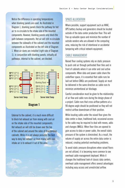
Notice the difference in operating temperatures when blanking panels are used. As illustrated in Diagram 1, blanking panels block the pathway for hotair to re-circulate to the intake side of the mountedcomponents. However, blanking panels only block thepath between components. Hot air will still re-circulatebetween the sidewalls of the cabinet and the mountedcomponents as illustrated on the left side of Diagram1. When air dams are installed (right side of Diagram1), in conjunction with blanking panels, virtually all pathways, internal to the cabinet, are blocked.
External to the cabinet, it is much more difficult to block hot exhaust air from mixing with cool air on the intake side of the mounted components. Hot exhaust air will still be drawn over the top of the cabinet and around the sides of freestandingcabinets. While it is not always possible, the best way to deny hot exhaust air from mixing with coolintake air is to exhaust it out of the area.
SPACE ALLOCATION
Where possible, support equipment such as HVAC, UPS battery backup and generators should be locatedoutside of the data center production floor. This willfree up valuable space and minimize the number ofoutside vendors who are allowed in the computingarea, reducing the risk of intentional or accidentaltampering with critical network equipment.
CABLE MANAGEMENT
Raised floor cooling systems rely on static pressure to push cold air through perforated floor tiles and infront of cabinets where it can enter and cool activecomponents. When data and power cable share theunderfloor space, it is essential that cable runs belaid out before CRACs are positioned. Supply air mustbe delivered in the same direction as cable runs tominimize unintentional air blockage.
Careful consideration must be given to the relationshipof air flow and cable runs during the design phase ofa project. Cable runs that cross airflow patterns at a90-degree angle should be positioned so they will notrestrict airflow downstream of their position.
While locating cable under the raised floor gives thedata center a clean, traditional look, occasional accessto the cable may be required to deal with moves, addsand changes (MACs). When floor tiles are opened togain access to data or power cable, the overall staticpressure of the system is diminished. As a result, thevolume of supply air across the entire data center isreduced, creating potential overheating problems.
To avoid static pressure disruptions when raised floorsare not utilized, it is becoming more common to seeoverhead cable management deployed. While itchanges the traditional look of classic data centers,overhead cable management offers several advantagesincluding easy access and unrestricted airflow.
Side
Server Inlet Temp
90º F (32º C)80º F (27º C)95º F (35º C)
83º F (28º C)72º F (22º C)70º F (21º C)
Side
Server Inlet Temp
79º F (26º C)73º F (23º C)73º F (23º C)
73º F (23º C)72º F (22º C)70º F (21º C)
Blanking Panel
Diagram 1

10 |
|Section 2 - Data Center Design Considerations
ACCESS FLOORS
One of the key predesign considerations that affectsalmost every aspect of success within a data centerenvironment is the access floor, or “raised floor” as it is often referred to. This infrastructure is every bit asimportant to cooling, equipment support, grounding,and electrical and communications connectivity as thebuilding structure supporting it. When an access flooris chosen as a means to distribute services to the datacenter, there are many criteria to consider regardingthese utilities. Some of these include:
• Seismic and vibration considerations
• Need for equipment to be bolted to and stabilized by the flooring structure
• Positioning of equipment to provide easy access to removable tiles and raceways beneath
• Spacing of access, cooling and maintenance aisles
• Panel strength and airflow requirements
• Electrical bonding and anti-static conductive needs
• Rolling, ultimate and impact load capacities
• Minimum height requirements for easy access.
These environmental conditions will necessarily dictatethe choice of stronger grids, panel construction, surfacelaminates and overall design considerations. As theaccess floor grid is often one of the first structures in place prior to any cabling or equipment, it is oftenthe victim of harmful disruption. Often, as the cabletray, power or communications infrastructure is laid, the grid is disturbed and “squaring” or stability iscompromised, causing numerous undesirable issues to occur. For example, tiles may not fit and groundingmay be compromised. The best way to ensure overallsuccess and minimal delay is to spend more time oncoordinating professional trades, understanding support equipment, and planning, designing and carefully selecting the access floor material.

|11
Section 3 - Data Center Infrastructure Considerations|
SECTION 3Data Center InfrastructureConsiderations
Racks, Cabinets and Support Infrastructure 12
Redundancy and Path Diversity 12
Security 13
Storage 13
Flexible and Adequate Connectivity 13
Choosing the Appropriate Cabling Media 13
Data Center Cabling Considerations 14
Copper vs. Fiber Cable and Connectivity 15
The Case for Fiber 16
Fiber Use in the Data Center 16
Benefits of Preterminated Fiber Solutions 18
50- vs. 62.5-micron Fiber 18
Copper Media and the 21st Century Data Center 19
Types of Copper Cable Construction 20
Limited Combustible Cable 20
Power Cables and Accessories 21
Electrical Power System Considerations 23
Energy Efficiency and Environmental Considerations 23
Intelligent Infrastructure Management (IIM) 24
KVM Switches 26
12 |
|Section 3 - Data Center Infrastructure Considerations
RACKS, CABINETS AND SUPPORT INFRASTRUCTURE
Data centers employ a wide variety of racks, enclosuresand pathway products such as cable trays and ladderracking. There are numerous variables to considerwhen selecting the right product. They must all in someway, individually and collectively, support four key areas.These areas include:
• Climate control, namely cooling and humidity
• Power management
• Cable management
• Security and monitoring.
Configurations vary between CDC and IDC models. In a corporate data center, a typical enclosure mighthouse 12 to 24 servers with a switch and a monitor generating a heat load in excess of 4,500 watts. It is easy to understand how cooling problems canarise in such a scenario. Even with computer roomcooling and a fan at the top of the cabinet, there can be a wide disparity in temperature at the top versus the bottom of the enclosure.
Racks and cabinets must often meet seismic (Zone 4)requirements as defined by the Telecordia GR-63-COREStandard, the Network Equipment Building System (NEBS),as well as load bearing and server depth specifications.These support structures must also provide effectivecable management. There are many unique designsand innovative approaches that can help ensure neat,manageable bundling and routing of cables withmechanical protection, stability and flexibility.
Data centers also vary widely in their approach to inter-cabinet or inter-rack cable distribution. Many prefer cable runway below an access floor, while others have adopted an overhead ladder rackapproach. Still, others see unique merit in each anduse both systems. Overhead ladder rack allows formore convenient access to cables, making moves,adds and changes easier. On the other hand, underfloor runway provides more security and cleaner aesthetics though future changes and a blockage of airflow may become an issue.
REDUNDANCY AND PATH DIVERSITY
Redundancy and path diversity are considerations inCDC and IDC environments for power, cabling, Internetaccess and carrier services. Tolerance for downtimemeasured against added equipment costs and “support area-to-raised floor” ratios must be closelyexamined and matched. Based on these criteria, datacenter developers and operators design and implementdifferent infrastructures. Corporate data centers mustcarefully weigh the cost of downtime with respect totheir revenue model. If outages prevent order entry,particularly during peak conditions or seasonal surges,business management must ensure that IT providesthe availability and reliability to consistently meetthose demands. In the IDC arena, many operatorsmust strive to meet or exceed the legendary “fivenines” of the public telephone network. In a nutshell,“five nines” reliability equates to slightly more thanfive minutes downtime annually for 24-hour servicelevels. It is a challenge in the data world to achievethat level of reliability, yet that is the customer expectation. N+1 and 2(N+1)* component redundancy is required to meet these objectives. This desired level of stability creates a cascading effect on capital investment, usable revenue generatingfloor space versus support equipment space and dollars invested per square foot. *Note–see page 21 for explanation.

|13
SECURITY
Data centers are the lifeblood of information. Companyand customer data should be treated like money in abank vault. Corporate and Internet data centers musttake definitive measures to limit access only toauthorized personnel, and ensure use of proper fireprevention and life safety systems while minimizingthe potential of equipment damage. Video surveillance(CCTV) and biometric or card access control are oftensufficient in CDCs, but in IDCs, where personnel mayoften come from many different companies (sometimesfrom the competition), additional security is required.Besides perimeter-type security, compartment securityis recommended via locked cabinets or collocationcages, and additional provisions for cable raceway and raised floor access become necessary to achievecustomer comfort levels. In addition, real-time personnel and asset tracking may be used.
STORAGE
Storage in both corporate and Internet data centersmay migrate to the storage area network (SAN) modelover time as the volumes of stored data escalate andthe management of content becomes more challenging.Additional or complementary connectivity concernsmust be addressed in the data center design toaccommodate for flexibility and the most efficient and effective use of space. The use of Fibre Channel
technology and 50-micron multimode optical cablingmay cause the re-evaluation of overall distributiondesign. As other data link level transport methods(such as 10 Gigabit Ethernet) are evaluated and/orstandardized for use in SANs, there may be an advantage to using the same fiber type to interconnectstorage systems and servers throughout the data center.
FLEXIBLE AND ADEQUATE CONNECTIVITY
Adequate connectivity is key to bringing users onlinequickly and efficiently, whether in a corporate or IDCenvironment. Time is money, whether provisioning newdata center customers, upgrading their bandwidth orleased services, or providing quick, coordinated and efficient moves, adds and changes service. Choice of media in the data center may be more critical thanin other wired areas, just as equipment reliability andredundancy is more critical in a hospital operatingroom than in business offices. Performance, flexibility,headroom, patching and error-resistance are all variables in the same crucial design formula.
CHOOSING THE APPROPRIATE CABLING MEDIA
Choosing the appropriate cabling media can affectmany aspects of data center design. An entire projector facility must be considered with respect to systemsand manufacturer connectivity requirements not onlyfor present day needs but also for future requirements.Standard distance limitations and cabling performancemust be considered up front to prevent additionalcosts and potential service disruption. In other words, the best layout is one that allows any piece of equipment to be reached from anywhere within the data center without breaking any distance rules. The expected life of the cabling should be consideredin respect to supporting multiple generations of electronic equipment and bandwidth performanceimprovements, with minimal requirements for pullingup floor tiles or adding media to overhead raceways.
Section 3 - Data Center Infrastructure Considerations|

14 |
|Section 3 - Data Center Infrastructure Considerations
The ANSI/TIA/EIA-942 standard recommends ANSI/TIA Category 6/ISO Class E as the bare minimum coppercable. Category 5 and Category 5e/ISO Class D are not recommended for use in data centers because neither will support 10 Gigabit Ethernet.
Over the past few years, the Institute of Electrical and Electronics Engineers (IEEE) has completed extensive work on the 10 Gigabit Ethernet standard. As 10 Gigabit Ethernet becomes more widely used,particularly in utilizing copper twisted-pair media, data centers will benefit. Structured cabling, any-to-anypatch fields and high-performance copper patchcables make data center management and operationsvery economical and efficient. The TIA standard forAugmented Category 6 twisted-pair (including UTP) orISO Class EA cabling channels will provide the bestinvestment protection for data centers since manyservers, and potentially storage area networks will ultimately be connected through 10 Gigabit Ethernetlocal area networks (LANs) and SANs. In the area ofstorage networks, 10 Gigabit Ethernet presents someopportunity for creating IP-SANs utilizing the InternetSmall Computer System Interface (iSCSI) protocol as analternative or in addition to Fibre Channel. The sameflexibility planners and operators gain from 10 GigabitEthernet copper and fiber LAN connectivity in the datacenter environment can be employed with SANs. Whenoptical fiber is required or desired in the data center,ANSI/TIA/EIA-942 recommends laser optimized multimode50-micron/ISO OM3 although the standard permits62.5-micron/ISO OM1 products. Read more about the standards in Section 4.
DATA CENTER CABLING CONSIDERATIONS
Data center design and cabling infrastructure architecture has evolved over the years as needs and technologies change. In the past, the data centermanager relied on experience as well as solutions that previously worked and did not work. Planningtoday’s data center, however, requires a more rigorousapproach due to the faster pace at which the datacenter is changing.
A data center cabling system may require a balance ofboth copper and fiber to cost effectively meet today'sneeds and support the high-bandwidth applications of the future. Rapidly evolving applications and technologies are drastically increasing the speed and volume of traffic on data center networks. Ensuringthat a cabling solution is designed to accommodatethe higher transmission rates associated with theseevolving bandwidth intensive applications is critical.
The standards committees recognize the evolvingneeds of the industry and are reacting. ISO is currentlyin the process of developing cabling standards forextending the bandwidth in copper and 50-micronfiber to support the growing requirements.
The structured cabling architecturecommonly used for data centersrequires a reliable high-performance,high-density design with flexibleguidelines for quick installation,future readiness and easy-to-useapplications.

|15
Section 3 - Data Center Infrastructure Considerations|
In order to address these criteria, the following mustbe considered and prioritized:
• The sophistication of the network applications
• The kind of traffic expected on the various portionsof the data center network based on number ofusers, data transfer requirements of each user, LAN architecture, etc.
• The life expectancy of the network and cabling infrastructure
• The frequency of moves, adds and changes
• The growth potential of the network over its expected life
• Any adverse physical conditions in the customer’s data center
• Any access restrictions whether physical or time related
Customers are looking for high-performance solutions for a more effective overall operation of their data center network. Manageability is essential; without it,the cabling infrastructure takes over the data center in a short amount of time. To increase control over the data center infrastructure, structured cabling shouldbe implemented. The key benefit of structured cabling is that the user regains control of the infrastructurerather than living with an unmanageable build-up ofpatch cords and mass of cables under the floor.
The initial data center must be designed so it can bescaled quickly and efficiently as its requirements grow.To meet the requirements and demands of the datacenter, the topology in the data center as well as theactual components used to implement the topologymust be explored.
Several factors affect cable selection including thetype of solutions used (field termination versus factorytermination); conduit needs (innerduct versus interlockingarmor); cable tray/conduit space availability (cable density/size requirements) and the flame rating of the installation area (NEC requirements).
CABLING INFRASTRUCTURE: COPPER VS. FIBER CABLE AND CONNECTIVITY CONSIDERATIONS
Choices between fiber, copper or the selective use of both depend on a variety of criteria including:
• Bandwidth and performance required per data center area
• Immunity to Electromagnetic Interference (EMI)and Radio Frequency Interference (RFI)
• Need for density and space saving connectivity
• Flexibility and speed of reconfiguration
• Device media interface considerations
• Standardization
• Future vision and tolerance for recabling
• Cost of electronics.

16 |
|Section 3 - Data Center Infrastructure Considerations
THE CASE FOR FIBER
Fiber can provide numerous advantages over copper in a data center environment.
• Fiber systems have a greater bandwidth and error-free transmission over longer distances allowing network designers to take advantage of new data center architectures.
• Cost of fiber optic solutions is comparable with extended performance copper cabling (Category 6A/ISO Class EA and Category 7/ISO Class F).
• Optical data center solutions are designed for simple and easy handling and installation.
• Fiber systems are easier to test.• Optical fiber is immune to EMI/RFI.• Faster installations (up to 75 percent faster) offer
time and cost savings to data center developers,operators and contractors.
• High-density fiber optic systems maximize valuablespace. Fiber’s small size and weight requires lessspace in cable trays, raised floors and equipmentracks. As a result, smaller optical networking provides better under-floor cooling and gives precious real estate back to the data center.
• Fiber has the ability to support higher data rates,taking advantage of existing applications andemerging high-speed network interfaces and protocols.Multimode fiber optics support:
- 10 Mbps/100 Mbps/1 Gbps/10 Gbps Ethernet- 1/2 /4 Gbps Fibre Channel
• Fiber provides “future proofing” in network infrastructure.
• Laser optimized 50-micron/ISO OM3 fiber is generally recommended by storage area networkmanufacturers because of its higher bandwidthcapabilities.
• The next IEEE proposed Ethernet speed will be for 40 Gbps and 100 Gbps only over fiber and ashort distance of 10 meters over copper.
FIBER USE IN THE DATA CENTER
Data center wide area network (WAN) connectionsvary, but most IDCs are typically fed with at least two redundant and diversely routed OC-48 (2.5 Gbps)fiber pairs. Some will soon have OC-192 (10 Gbps)connections and higher. Corporate data centers typically subscribe by increments of T1s (1.5 Mbps) or T3s (45 Mbps) and in some metro areas, 100 Mbpsnative Ethernet speeds and higher are available. Bandwidth distributed to servers and other devicesmay range from 1 Gbps to 10 Gbps or more dependingon applications and data center models.
In CDCs, cabling infrastructure often mimics the commercial building distribution model with fiber usedin the backbone (such as a vertical riser) and copperused to connect the servers (similar to horizontal distribution). While some IDCs follow this model, thereis an increasing trend to take fiber as close to thedevices as possible. Fiber can provide increased bandwidth with multimode supporting up to 10 GbpsEthernet. Fiber can also provide up to 60 percentspace savings over copper cabling. This can be animportant factor as equipment density and heat dissipation needs increase. Space below access floors is getting crowded and can seriously restrict airflow needed for cooling. Interlocked armor jacketingcan also provide additional protection if necessaryand further reduce the need for underfloor raceway.
Fiber termination and patching equipment now allowup to 96 fibers to be terminated in one rack space (1U).This feature makes it attractive in some designs to terminate fiber close to server cabinets or racking rows(or even within them). While many servers now comein 1U configurations with dual Ethernet interfaces,some have started to appear with optical connectionsas well. This trend toward optical networking wouldbenefit from a flexible “fiber or copper last meter”flexible patching point within a server cabinet row. This design, while providing the maximum flexibility
|17
Section 3 - Data Center Infrastructure Considerations|
and growth insurance, has many variations anddepends entirely on the data center operator’s business objectives.
Interestingly enough, the use of fiber over copper is no longer as much a cost consideration as it hasbeen in the past. In the data center environment, most agree that 10 Gigabit Ethernet will be common,so if copper media is to be used, only the highestavailable grade of cabling (Category 6A/ISO Class EA orCategory 7/ISO Class F) will provide the required errorfree transmission, headroom and performance criteria.Today, the cost of a high-quality copper channel is economically equivalent to a fiber solution if electronicsare not a factor. A fiber solution may provide otheradvantages such as extended distance (beyond 100meters) and EMI/RFI protection. Installation cost also isfavorable with fiber, particularly when a modularizedpreterminated solution is adopted, often yielding 75 percent savings over a field-terminated approach.For example, installing preterminated fiber in a large(100,000 sq. ft./10,000 sq. m+) data center can takeas little as 21 days to purchase and install along withoffering easy and effective moves, adds and changesas well.
Traditional vs. Preterminated Fiber SolutionsIn commercial building installations, an optical fibercabling link is typically assembled in the field at thejob site. The cable is pulled in from a reel of bulk cable,cut to length, attached to the patch panel housing and terminated with field installable connectors on each end. The terminated ends are then loaded into adapters in rack or wall mountable housings.
Finally, the complete link is tested for continuity and attenuation.
The most efficient optical infrastructure is one inwhich all components are preterminated in the factory.Connectors are installed, tested and packaged in thefactory. The installer unpacks the components, pullsthe preconnectorized cable assembly into place, snaps in the connectors and installs the patch cordsconnecting to the end equipment. This is the fastestinstallation method and provides the best solution forturning up servers quickly and lessening the risk of not meeting the customer’s availability expectations.
The design and product selection process remains the same with selection and specification of fibertype, fiber count, cable type, connector type and hardware type appropriate for the environment.
WHY PRETERMINATED FIBER SYSTEMS?
• Up to 60 percent smaller optical networking solution freeing up raised floor and racking space
• Get online quicker with up to 75 percent faster installation
• Modular design for faster moves, adds and changes
• Defined accountability, built-in compatibility
• Factory terminations
• Consistent results from an ISO 9001 / TLQ 9000quality architecture
• Systems are factory tested before shipment, reducing risk
• Eliminates variability in material costs

18 |
|Section 3 - Data Center Infrastructure Considerations
BENEFITS OF PRETERMINATEDFIBER SOLUTIONS
With a little planning prior to ordering, preassembledsolutions offer several advantages over the traditionalinstallation. • An optical fiber link can be quickly and easily
installed. This is advantageous for projects where system downtime must be minimized or where disruption of the floor space cannot be tolerated.Therefore, a preassembled solution can be useful to have on hand for emergency repairs or for the re-cabling of a facility.
• A preassembled solution can be useful where costcontrol of a project is important. The completion of the labor assembly steps at the factory can significantly reduce the variability of installationcost in the field.
• A preassembled solution can increase the versatilityand productivity of the installation crew with fewerdemands on specialized tooling and installation skills.
• An optical fiber link can be completely assembledand tested prior to leaving the factory. (This does not completely remove the need for field testingafter installation for link certification.)
IN SUMMARY
The labor savings associated with using factoryterminated cables in most instances make it a moreeconomical solution than field termination of fiber cables.Not only do factory-terminated cables eliminate the laborcosts associated with installing connectors in the field,they also eliminate the need to spend money on redoingwork that has failed as well as the cost of additionalconnectors. Factory terminated cable comes from the manufacturer where it was prepared under thesupervision of fiber optic experts in an environmentallycontrolled setting with quality inspection and testing.Connectors are attached to individual strands of fiberin an automated factory process that is not as subjectto human error. Once attached to the fiber cable, theconnections are tested to ensure quality and performance.
50- VS. 62.5-MICRON FIBER
In terms of physical properties, the difference betweenthese two fiber types is the diameter of the core—thelight-carrying region of the fiber. In 62.5/125 fiber, thecore has a diameter of 62.5 microns and the claddingdiameter is 125 microns. For 50/125, the core has adiameter of 50 microns with the same cladding diameter.The diameter measurement of the fiber core has an inverserelationship to the effective bandwidth and the distancelimitations of the fiber. As the core size decreases, thebandwidth and distance capabilities increase.
Bandwidth, or information-carrying capacity, is specified asa bandwidth-distance relationship with units of MHz-km(megahertz over one kilometer). The bandwidth needed to support an application depends on the data rate oftransmission. As the bandwidth (MHz) goes up, the distance that bandwidth can be transmitted (km), goes down. A high-bandwidth fiber can transmit more information for longer distances.
While 62.5-micron/ISO OM1 fiber has been the most common multimode optical cable used in local area network applications, 50-micron/ISO OM3 fiber is the standard for storage area networks and their Fibre Channel data link connectivity. The 50-micron/ISOOM2/OM3 fiber was chosen because it supports longerFibre Channel cabling distances (such as 150 m at 400Mbps using short wave length 850 nm optics) when compared with 62.5-micron/ISO OM1. This is also true for Gigabit Ethernet (600 m) and exceeds the computerroom objective of 100 meters for the 10GBASE-T standardfinalized in June 2006. The increased information-carryingability and adoption for SAN/Fibre Channel usage withindata centers has changed the design recommendation tolaser optimized 50-micron/ISO OM3 fiber throughout thedata center. One such IDC design envisions Ethernet andFibre Channel distribution switches sitting between server cabinet rows and SAN equipment, providing any-to-anyconfiguration capabilities and a migration path to all optical networking within the data center.
|19
Section 3 - Data Center Infrastructure Considerations|
COPPER MEDIA AND THE 21ST CENTURY DATA CENTER
Today, there are high-performance copper cabling solutions that are capable of supporting 10 GigabitEthernet reliably up to 100 meters. With the publicationof the IEEE 802.3an standard in June 2006, the use of100-ohm twisted-pair cabling media to support 10 GigabitEthernet, otherwise known as 10GBASE-T, became areality. Up until the publication of the 802.3an standard,the only other Ethernet-based protocol specifying theuse of copper cabling as its transmission medium was the IEEE 802.3ak or 10GBASE-CX4 standard. Although10GBASE-CX4 supports 10 Gbps data transmission, itslimited transmission distance of 15 meters and incompatibility with the more common RJ45 physicalinterconnect limited its adoption in the market. Theselimitations do not exist with 10GBASE-T. 10GBASE-T hasthe advantages of lower transceiver costs when compared to 10 Gigabit Ethernet optical modules and100 meter reach using structured wiring systemsbased on the RJ45 connector. These attributes willcontinue the deployment of copper twisted-pair cablingfor horizontal, or non-backbone, distribution betweenLAN switches and servers. Only the best Category6A/ISO Class EA or Category 7/ISO Class F media thatexceed the minimum standard guidelines for datatransmission with full channel performance should be considered.
It is important to keep in mind the strengths of eachsystem and install products with characteristics thatmatch the equipment or service demands. One suchexample involves using Category 6A/ISO Class EA patchcords as a transition point between fiber-connectedEthernet switches and copper-interfaced servers withinserver cabinet rows or “racking neighborhoods.” Thesehigh-end cables will provide ample bandwidth andmore than enough insurance against dropped packets.
Note: See Section 4 for more information on coppertwisted-pair solutions for data centers.
Copper or Fiber? There are three strong reasons for the broad acceptanceand rapid growth of twisted pair as the horizontal medium:low initial cost, the ability to deliver higher data rateLAN services and the flexibility to use one medium forall services. As speeds increase, copper-based LANswill require more complex and expensive electronics.Although, fiber’s significant bandwidth distance givesit advantages over twisted pair in centralized architectures. However, a centralized architecture maybe inappropriate or impractical to implement in manycurrent building environments. In addition, in a traditional hierarchical star architecture, fiber losessome of its hard-fought advantages.
In the majority of situations, copper cabling remainsthe preferred choice for the final link to the desktop, andother short links such as those found in data centers.
Cost Considerations The initial 10 Gigabit Ethernet standard was undertakenby the IEEE 802.3ae committee, based primarily onfiber optic technology. Although the enterprise 10Gigabit fiber electronics are maturing and gainingacceptance, they still remain costly compared to copper. The initial cost of 10 Gigabit copper systems is projected at 40 percent of 10 Gigabit fiber productsand is expected to widen over time. Hence, at shorterdistances with a large number of links, 10 Gigabitcopper based versions become more attractive.
Growth in 10 Gigabit Copper Solutions 10 Gigabit Ethernet technology continues to evolve andimprove,causing wider adoption. Blade servers, networkedenterprise switches, video servers and other applicationscan benefit now from 10 Gigabit speeds in storage,system backup, teleconferencing and surveillance.Technical advances have enabled the higher density,reduced power and improved cost-effectiveness needed to attract all of the major system developers. The development of 10GBASE-T by the IEEE 802.3ancommittee is expected to only accelerate this market acceptance.

TYPES OF COPPER CABLE CONSTRUCTION
One step that can help protect a data center in case ofa fire is to look at cable construction. Cable is one of thelargest fire fuel sources in the data center. The three typesof typical communication cable construction are general-use CM, CMR riser and CMP plenum cables.These are combustible because they will eventuallyburn. A fourth cable type is called limited combustiblecable or LCC, and its performance in laboratory tests is considered to be outstanding. Both the jacket and the insulation are made of 100 percent FEP or Teflon®
compounds. CMP plenum cable gets a significantly better rating than CMR riser or CM largely because of the flame retardant jacket over the primary conductor insulation of Teflon. See the sidebar to learn about somecompelling reasons why data center operators consider using Limited Combustible Cable to protect people and equipment.
Currently, the use of LCC is voluntary. It is neitherrequired nor prohibited based on its superior fire andsmoke limiting characteristics. However, the NationalFire Prevention Association (NFPA), which publishes the National Electrical Code (NEC), is considering it for inclusion in a future code revision.
Many companies are starting to use LCC. Insurancecompanies are studying test results to determine ifthere should be financial incentives to stimulate adoption.The clear benefit in data center environments is thesuperior smoke particle deterrence.
Low-Smoke Halogen-Free (LSZH) cables are specified in many countries across Europe. Although these cablesburn, they do not give off any toxic fumes and only limited smoke. These cable types meet various specifications across Europe covered by the IEC standards group.
20 |
|Section 3 - Data Center Infrastructure Considerations
LIMITED COMBUSTIBLE CABLE IN ACTION
In tests conducted at the DuPont labs in England, four cable types were subjected to a 1-megawattflame in a simulated plenum space. CMR combustionand noxious smoke was prevalent within two-and-a-half minutes of being exposed to the flame. Withinnine minutes, the fire spread downstream and becamea full-fledged cable fire half a minute later. The samepair count cable in a CMP construction, a plenumrated cable with FEP jacket, caught fire within two-and-a-half minutes but with much lower smokeproduction. The fire spread downstream in seven toten minutes and continued burning at a fairly constantrate as opposed to the rapid incineration of thePE/FRPVC insulated riser cable.
The limited combustible cable provided an altogetherdifferent picture with no appreciable smoke or fire either at the point of exposure to the flame or downstream after enduring the same conditions for more than 25 minutes.
FEP Insulation
Standard "Combustible" CMP Cable
FRPVCJacket
Copper Conductor
FEP Insulation
Limited Combustible Cable
FEPJacket
Copper Conductor
Cable Type
LCC(Plenum)
CMP(Plenum)
CMR(Riser)
CM(General PurposeCommunications)
Insulation
FEP
FEP
PE
PE
Jacket
FEP
FRPVC*
FRPVC*
FRPVC** Different Compounds
FEP Insulation
Standard "Combustible" CMP Cable
FRPVCJacket
Copper Conductor
FEP Insulation
Limited Combustible Cable
FEPJacket
Copper Conductor
Cable Type
LCC(Plenum)
CMP(Plenum)
CMR(Riser)
CM(General PurposeCommunications)
Insulation
FEP
FEP
PE
PE
Jacket
FEP
FRPVC*
FRPVC*
FRPVC** Different Compounds

|21
Section 3 - Data Center Infrastructure Considerations|
POWER CABLES AND ACCESSORIES
Power cables are the lifeline of any data center. Theselection of power cables that meet all requirementsfor performance, reliability and safety—and whichprovide these characteristics at a reasonable cost—involves a number of important considerations.
One of the first and most important considerations is to determine how much total electrical power willbe needed. Data centers typically require 35 to 250watts per square foot of floor space depending onequipment densities, data processing speeds, powerreliability (uptime) requirements and possible futureequipment upgrades. One method of determiningpower requirements as a function of reliability is to classify the facility into Tiers (I through IV) usingthe guidelines given in Annex G.5 of ANSI/TIA/EIA-942.
The power requirements for the data center should be dictated by the Tiering level that a customer wishes to achieve. The Uptime Tiers are covered in ANSI/TIA/EIA-942 standard as well as in Anixter’s Standards Reference Guide in greater detail.
Total data center power requirements are also sometimes calculated from the number of rack locations and the average power consumed by eachrack. This is often done on a row-by-row basis toimprove accuracy. The specific type of electrical load(circuit voltage and current, AC or DC, single- or three-phase, etc.) and the location of each within thefacility must also be determined. Adequate electricalpower for heating, ventilating, air conditioning, lightingand other utilities must be carefully planned as well.
Distribution of electrical power throughout a data center facility is accomplished with a large array ofcomponents. Required, for example, are transformers,switchgear, service-entrance panels, breakers, distributionpanels, emergency backup generators, automatictransfer switches, batteries, control panels, wire andcable, junction boxes, plugs, receptacles, etc.
Raceways and/or cable trays are also required for protection and support of the installed wire and cable.The choice of raceway versus cable tray primarilydepends on National Electrical Code requirements,technical requirements and cost. There are over adozen raceway types from which to choose includingmetallic and nonmetallic versions of rigid conduit,electrical metallic tubing (EMT), electrical nonmetallic
Number ofDelivery Paths
Tier I:Basic
Only 1 Only 11 Active,1 Passive 2 Active
N N+1 N+1 2 (N+1)
20% 30% 80-90% 100%
20-30 40-50 40-60 50-80
20-30 40-50 100-150 150+
Tier II:RedundantComponents
Tier III:Concurrently Maintainable
Tier IV:FaultTolerant
RedundantComponents
Support Space toRaised Floor Ratio
Initial Watts/ft
Ultimate Watts/ft

22 |
tubing (ENT), wireway, surface raceway, flexible metalconduit and liquid tight flexible conduit. Cable traytypes include those made of steel or aluminum andencompass a large variety of strengths, widths,depths, rung spacing and lengths. The requirementsand permitted uses for the various raceway types as well as cable tray are covered in articles 300 to 400 of the NEC. In Europe, the CENELEC EN50174standards should be referenced.
For data centers located in the U.S., power cables andtheir installation must usually comply with the NEC aswell as any applicable state or local codes. Althoughthe NEC does not officially apply to “installations ofcommunications equipment under the exclusive controlof communications utilities,” virtually all utilitieschoose to comply to reduce their potential liability as well as their insurance premiums. For Canadianinstallations, the Canadian Electrical Code (CSA C22.1)applies rather than the NEC (NFPA 70). The codes ofboth countries require the use of specific UL Listed orCSA Certified cables in each application. For example,cables installed in cable trays must meet certain firetest requirements to minimize fire propagation in theevent of a fire. One power cable type frequently usedin tray in U.S. data centers is NEC type RHH (per UL44) with a “For CT Use” rating. This optional rating isbased primarily on fire test performance and is one of many specific ratings that permit a cable to beinstalled in tray. Other optional ratings include ST1(limited smoke) and LS (low smoke) ratings that verifya cable meets specific smoke emission requirementsin UL 44. These ratings are not required by code. Data center power cables are also sometimes knownas “KS spec” cables, which is a reference to centraloffice power cable standards that have been in use forroughly half a century. KS power cable specificationsare owned by Tyco Electronics Power Systems andinclude cable standards such as KS-24194™ and KS-22641.™ Other power cable and power cableinstallation standards often applicable to data centers
include NEMA WC 70 (ICEA S-95-658), Telcordia GR-347-CORE, Telcordia GR-1275-CORE, ANSI/TIA/EIA-942 and ANSI-J-STD-607-A-2002. The TIA standard includes information on the selection,design and placement of power and grounding systemswithin a data center. The ANSI standard covers thedesign of the grounding and bonding infrastructure.
In Europe, power cables and their installation mustcomply with the European electrical codes as well asany applicable local codes. The electrical codes ofsome countries require the use of specific cables ineach application. For example, cables installed incable trays must meet certain fire test requirements tominimize fire propagation. Another frequently specifiedrating, the "low smoke" rating, is not required by codebut verifies the cable meets the European standardsfor smoke emission requirements.
Other cable types are permitted in other locationswithin a data center. For example, NEC Article 645 onInformation Technology Equipment spells out in detailthe types of cables permitted under the raised floor of a computer room including NEC power cable typessuch as TC (tray cable), MC (metal clad), AC (armorclad), NPLF (non-power-limited fire alarm cable) andtype DP (data processing cable). If installed in conduit, additional cable types can also be used.
In addition to making sure all power cables meet applicable codes and standards, many engineering decisions are necessary concerning cable characteristics.These include characteristics such as conductor size, voltage rating, cable flexibility (ASTM Class B or Class Istranding), with or without cotton braid, insulation colorRoHS (Restriction of Hazardous Substances) compliance, etc.
Conductor size is primarily based on ampacity, voltagedrop and energy efficiency considerations, while grounding conductor size depends on the rating of the overcurrent device protecting the circuit. Minimumgrounding conductor sizes are given in Table 250.122 of the NEC.
|Section 3 - Data Center Infrastructure Considerations
|23
Power cable accessories also need to be carefully considered.This includes decisions on whether to install the cable in conduit or tray, size of the conduit or tray, strength of supports,method of securing the cable (lace, nylon cable ties or other),grounding conductor bonding methods and maximum tray orconduit fill permitted by code. The method of securing thecable is especially important for DC circuits because of thepotential for significant cable movement resulting from themagnetic forces created by high fault currents.
Cable accessories such as lugs, barrel connectors, taps, fittings (also referred to as glands or connectors), etc. must beselected and coordinated with the power cable in mind to prevent last-minute sizing problems. For example, two differenttypes of conductor stranding are generally used in data centers: ASTM Class B “standard” stranding and Class I “flexible” stranding. Class I stranding is generally used for battery cables, cables that must be flexed in service or cablesthat are installed in unusually small spaces. Class I strandinghas more (but smaller) individual wires in a given conductorgauge (AWG) size than does Class B stranding. Because of theadditional space between wires in a Class I strand, conductorswith Class I stranding have a larger diameter. To accommodatethe larger diameter, lugs and connectors with larger insidediameters (before crimping) must be specified. These are commonly known as “flexible” lugs. Within Europe, two different types of conductor strandings are generally used indata centers: EN 60228 Class 2 “standard” stranding andClass 5 “flexible” stranding. Class 5 stranding is generallyused for battery cables, cables that must be flexed in serviceor cables that are installed in unusually small spaces. Class 5stranding has more (but smaller) individual wires than doesClass 2 stranding. Because of the additional space betweenwires in a Class 5 strand, conductors with Class 5 strandinghave a larger diameter. To accommodate the larger diameter,the lugs and connectors must have larger inside diameters(before crimping) than standard lugs. To ensure trouble-freeservice over the life of the installation, lugs and connectorsshould always be applied with the proper crimping tool, correct die and adequate preparation of the cable prior to crimping.
Section 3 - Data Center Infrastructure Considerations|
ELECTRICAL POWER SYSTEM CONSIDERATIONS
An on-time, trouble-free, start-up of a data centerfacility requires detailed preplanning of the entireelectrical power system. Careful integration of theprimary electrical system with UPS, battery and otherbackup systems is essential. Because of the largenumber of interrelated factors involved, the detaileddesign of the entire electrical power supply system–including cables, cable accessories and all othercomponents of the system –is usually best completedby a professional electrical design group experiencedin data center electrical power supply systems.
Energy Efficiency and Environmental ConsiderationsHigh-voltage DC power
• 20 - 40% more efficient than A/C conversion*• Reduces fossil fuel consumption
Cable plant media and design• Increases air flow• Improves cooling efficiency
Equipment layout• Promotes thermal management and
cooling efficiencyDeployment
• Reduces waste at the job site• Improves construction efficiency
Monitoring / Management• Environmental
– Improves operational efficiencies• Infrastructure
– Asset utilization, business resiliency, securityAlternative Power
• Solar• Wind• Fuel cells
* Source: Lawrence Livermore Lab
|Section 3 - Data Center Infrastructure Considerations
INTELLIGENT INFRASTRUCTURE MANAGEMENT (IIM) WITHIN A DATA CENTER ENVIRONMENT
Organizations are increasingly dependent on their IT networks to provide a competitive advantage as well as meet both customer and shareholder needs.These networks are becoming increasingly complexand are required to support a rapidly increasing numberof applications coupled with ever increasing levels of IT service availability. The migration toward the goalof “on demand,” high availability, converged enterprisenetworks is set to provide a considerable challenge to those organizations wishing to reap the undoubtedbusiness benefits. It will require significant systemdowntime reductions to achieve this goal and it isextremely unlikely that improvements of this magnitudecan be delivered by the manual infrastructure management systems and processes in use today.
The realization that the 100 percent availability of IT services will assume ever-greater significance has led to the introduction of IT service management. Setting the benchmark for “best practice” in servicemanagement is ITIL (IT Infrastructure Library), whichhas been adopted as the de facto global standard for IT service management.
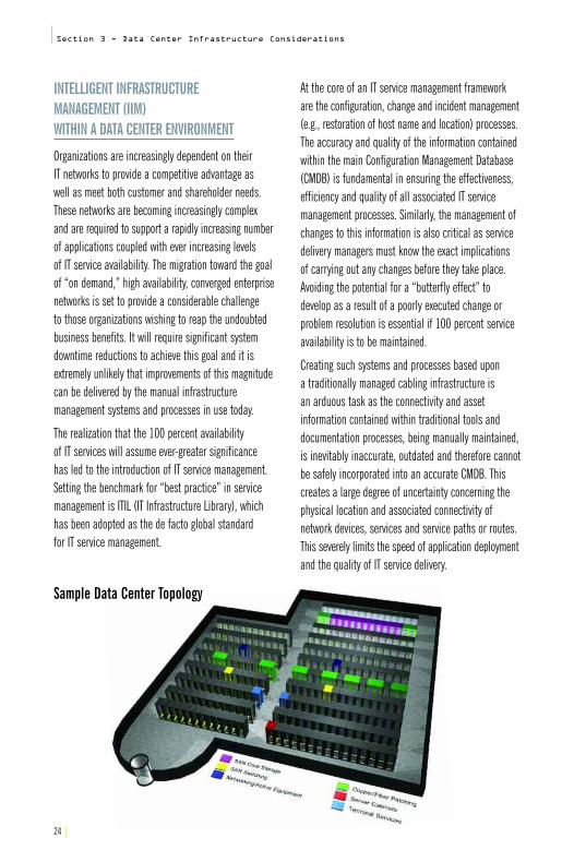
At the core of an IT service management frameworkare the configuration, change and incident management(e.g., restoration of host name and location) processes.The accuracy and quality of the information containedwithin the main Configuration Management Database(CMDB) is fundamental in ensuring the effectiveness,efficiency and quality of all associated IT service management processes. Similarly, the management ofchanges to this information is also critical as servicedelivery managers must know the exact implications of carrying out any changes before they take place.Avoiding the potential for a “butterfly effect” to develop as a result of a poorly executed change orproblem resolution is essential if 100 percent serviceavailability is to be maintained.
Creating such systems and processes based upon a traditionally managed cabling infrastructure is an arduous task as the connectivity and asset information contained within traditional tools and documentation processes, being manually maintained,is inevitably inaccurate, outdated and therefore cannotbe safely incorporated into an accurate CMDB. Thiscreates a large degree of uncertainty concerning thephysical location and associated connectivity of network devices, services and service paths or routes.This severely limits the speed of application deploymentand the quality of IT service delivery.
24 |
Sample Data Center Topology

|25
Section 3 - Data Center Infrastructure Considerations|
By adopting the correct “intelligent” sensor technologyand infrastructure management software tools as akey part of their cabling strategy, data center managerscan create a platform capable of addressing theseproblems, providing a 100 percent accurate, real-timetrusted source of connectivity and asset informationthat can be incorporated within the core CMDB andconsequently, utilized to enhance all associated ITservice management tools and processes. Any physicaladditions or changes to the network configuration arequickly and accurately planned and executed beforebeing automatically updated and reflected across all management processes, thereby optimizing process efficiency and aiding communication betweenwork streams and coordinating events. Unauthorizedevents/incidents affecting the infrastructure can be instantaneously identified and forwarded to the appropriate service management tool or team for rectification.
Not surprisingly, these process efficiencies and workstream productivity improvements can result in significant reductions in operational expenditure.In traditionally managed data centers, the addition of a new application server to a complex infrastructurerequires a considerable amount of intricate planningbefore it can be safely commissioned. Sufficient spacehas to be found within a cabinet, along with theappropriate power and environmental controls. Perhapsthe most complex and time consuming task (and onethat can be highly prone to error) is the planning ofthe multitude of cable routes required to run from theLAN, SAN and terminal services fabric (see SampleData Center Topology at left) to the server cabinet and consequently, the target server and its associatedNetwork Interface Cards (NICs). While managementtools exist to automate the space, power and environmental planning process, prior to the introduction of Intelligent Infrastructure Management,the planning of service routing was a long and complex manual process.
THE IMPACT OF INTELLIGENT INFRASTRUCTUREMANAGEMENT ON DATA CENTER OPERATIONS
• Reduced cost and increased effectiveness of IT operations
• Saves time and manpower required for planning and implementing change, performing audits andresponding to faults
• Optimization and automation of the change control process along with the elimination of configuration errors
• Reduced truck rolls equals reduced costs, particularly for “lights out” environments
• Real-time location and tracking of all network assets can drastically improve effectiveness of existing asset management tools
• Provides audit trails and reporting capabilities (for Sarbanes Oxley)
• More effective use of network resources–ensures optimum switch port utilization thereby avoiding unnecessary purchases
• Key personnel's core skills can be extended acrossthe entire enterprise network, ensuring a reducedneed for local familiarity
• Governance of sub-contractors and outsourcing service providers–ensures SLAs (Service Level Agreements) and billing are actively monitored and controlled

26 |
|Section 3 - Data Center Infrastructure Considerations
Leading Intelligent Infrastructure Management solutionsprovide an auto-service, provisioning capability withintheir work order management functionality that automatically routes the required services to the necessary location via the most efficient and effectivecable links. The work orders required to execute theactivity are automatically created, issued to the appropriate technician and managed by the IntelligentInfrastructure Management system. Any actions that do not adhere 100 percent to the work order are instantaneously identified and rectified if required.
Utilizing Intelligent Infrastructure Management solutionsto automatically provision services within the datacenter environment has been proven to reduce servercommissioning time by up to 80 percent, while simultaneously reducing the number of incidentscaused by poorly executed change. If incidents occur,Intelligent Infrastructure Management solutions candramatically reduce mean time to resolution (MTTR) by up to 40 percent.
The optimization of IT service management processesand the resulting improvements in work stream productivity and efficiency ensure that data centeroperators will attain the goals of continuous servicedelivery while maximizing the return on their IT investmentsand achieving enhanced customer satisfaction.
KEYBOARD, VIDEO, MOUSE (KVM) SWITCHES
Data centers are expanding to keep up with theincreasing amount of data in today’s rapidly growinginformation infrastructure. This proliferation calls forcost-effective solutions that can provide centralizedcontrol of IT devices in the data center.
As file, e-mail, Web and application servers began to increase on corporate LANs, their managementbecame more complex. (See Rising Server AdministrationCosts graph at right.) While servers typically do nothave their own KVM consoles, they still need to beconfigured, maintained, updated and occasionallyrebooted. KVM switch is short for keyboard, video andmouse. Traditional KVM switches connect directly tothe servers and require operators to have physicalaccess to the console. In this way, a single KVM switchcan be used to access and control an entire room orrack full of servers.
IP-based KVM switches allow administrators to expand their reach over distributed systems, improvesecurity and reduce costs and downtime. With a KVMover IP switch installed at the data center, IT operatorscan sit at a single workstation anywhere in the worldand have secure access and control of many servers in multiple locations across the globe. For this reason,server management with KVM over IP switches isbecoming the cornerstone of most data centers today.
KVM over IP technology delivers data centers withunsurpassed scalability and flexibility by providingcentralization and standardization. Unlike traditionalKVM switches, KVM over IP switches can transmit KVM information over standard TCP/IP connections.This approach leverages a company’s existing networkinfrastructure by enabling operators to control serversand other distributed IT assets remotely over local area networks and wide area networks using a singlecomputer located anywhere in the world.

|27
Section 3 - Data Center Infrastructure Considerations|
KVM solutions provide centralized control, scalability,remote access, security and flexibility as well as thefollowing benefits:
• Reduced costs, space and energy savings—KVM switches provide immediate paybacks in hardware savings, free up valuable physical space and reduce demands on electric power and cooling systems.
• Improved business continuity—KVM switch solutions allow “out-of-band” access to a company'sservers and other IT devices. As such, they allow IT personnel to access, control and manage thecompany's servers and/or serial devices even if the corporate network itself is down.
• Improved security via “lights out” operations—Advances in KVM technology allow users to be further and further away from connected devices.
• Improved staff productivity—The virtual reach provided by IP solutions has an additional benefit;all of a company’s IT experts can now manageservers or respond to incidents from wherever theyare, across the hall, at home or across a multi-sitenetwork. These “virtually” centralized humanresources can eliminate costly travel time.
• Accelerated incident response—Enterprise-wide,Web-accessible solutions can dramatically shortenincident response times since administrators cantake action from anywhere.
• Increased hardware platform and operating system independence—KVM switches work in heterogeneous server environments.
$200$180$160$140$120$100
$80$60$40$20
$0
Spending(USB$)
35
30
25
20
15
10
5
0'96 '97 '98 '99 '00 '01 '02 '03 '04 '05 '06 '07 '08
Source: IDC 2005
Rising Server Administration CostsCost of management and administrationNew server spending (USM$)Installed base (M units)

28 |
Factors You Should Consider When Building a Data Center:• Professional engineering
• Power requirements and cabling
• Adequate cooling
• Efficient allocation of space
• Proper racking, enclosures, pathways and access flooring
• Redundancy and path diversity
• Security
• Storage
• Flexible and adequate connectivity
• Copper or fiber cabling and management
• KVM switches
• Intelligent Infrastructure Management solutions
With so many variables to considerwhen building a data center, today’sIT and business leaders are cuttingnew trails through uncharted territory.The next few years will unveil thedevelopments, risks and rewards ofthe new economy as entrepreneurialinnovation and the digital age takeroot, powered by business technology,the Internet and brought to you through21st century data centers around theworld. Selecting the right infrastructurefor your data center will be key tomaintaining uptime 24/7, year round.
SUMMARY
When it comes to the communications infrastructure,Anixter can make several specific recommendations.While the ANSI/TIA/EIA-942 standard for data centersspecifies a copper minimum of Category 6/ISO Class Ecabling, Anixter recommends cabling to support 10Gigabit Ethernet in new data centers and during datacenter expansion. At minimum, a Category 6A/ISOClass EA “augmented” construction is needed to provide bandwidth in the 500 MHz range with provencontrol of alien crosstalk.
Anixter continues to recommend fiber in all backbones including the data center. Laser-optimized,50-micron/ISO OM3 is the fiber of choice—again to ensure the data center is ready whenever and wherever 10 Gigabit Ethernet becomes a requirement.Additionally, limited combustible cable has strong merit in limiting loss—both of life and property—and may be a requirement when the NEC is updated in the future.
It pays to use the latest security and monitoring technology to protect assets and uptime from internaland external threats. Video surveillance, access control and environmental monitoring are all areaswhere Anixter can provide its product expertise during the data center design and upgrade process.
Anixter understands the challenges facing today’sdata center professionals and embraces standardssuch as ANSI/TIA/EIA-942, which provides a comprehensive roadmap for success. Anixter supportsdata center customers in achieving their goals ofavailability, reliability and operational efficiency.
|Section 3 - Data Center Infrastructure Considerations

SECTION 4Best Practices for Data Centers: Data CenterStandards and Associations
ANSI/TIA/EIA-942 (Data Center) 30
Data Center Topology 32
Hot and Cold Equipment Aisles 34
Data Center Infrastructure Tiers 35
Uptime Institute Tiers 36
Protection of Data Center Assets 38
IEEE 802.3an (10GBASE-T Task Force) 39
ANSI/TIA-568-B.2-1(ADIO) and ISO 11801 Class EA 39
IEEE 802.3af and 802.3at (POE) 39
ANSI/TIA/EIA-569-B (Pathways and Spaces) 40
ANSI/TIA/EIA-606-A (Administration) 40
J-STD-607-A-2002 (Grounding and Bonding) 40
Standards and Power Cables 41
Data Center Associations 42
“Green” Data Centers and Buildings 43
LEED 43
|29
Section 4 - Best Practices for Data Centers: Standards and Associations|

30 |
|Section 4 - Best Practices for Data Centers: Standards and Associations
ANSI/TIA/EIA-942: DATA CENTER STANDARDS
Data Center Growth Drives Need for StandardsOver the past several years, more and more businesseshave moved to the Web. Corporations continue to recentralize their computing platforms after years of decentralization. The effects of globalization require around the clock access to systems, data andapplications. Disaster recovery and business continuityrequirements demand redundancy and other fail-safemethods to ensure financial stability. Mergers andacquisitions continue to stretch IT departments withsystems integration challenges. These trends are driving a renewal in new data center construction and upgrades to existing facilities.
Typically, the task of planning a new data center orupdating an existing one falls on the IT department.They will first identify needs and then research andsort through a myriad of approaches to complexdesign and construction requirements. Recently, datacenter projects were either the domain of consultantsand engineering firms that specialized in business-critical environments or left to IT departments tostruggle with on their own. To avoid “re-inventing thewheel,” many sought the guidance of peers in othercorporations or reached out to other members of thedata center community who had gained experiencethrough their own data center projects.
To address this growing need for information, theTelecommunications Industry Association (TIA), formed a workgroup to study the problem and developa standard. The result of several years of work wasANSI/TIA/EIA-942, which was finalized in June of 2005.This standard has both familiar and unique aspects toit. It borrows from the well-established TIA cablinginfrastructure standards. However, ANSI/TIA/EIA-942 isunique because it was developed not only by standardsbody members but also by a cross section of the ITcommunity including engineers, manufacturers, architects and end-users. Similar to the educationalmovement that resulted in commercial building wiringstandards and cabling performance over the last decade,the data center now moves away from proprietarycabling systems and benefits from some commoninfrastructure standards.
The resulting ANSI/TIA/EIA-942 Telecommunications Infrastructure Standard for Data Centers is a 142-page,copyrighted document available for purchase throughGlobal Engineering Documents at 1-800-854-7179 orwww.global.ihs.com. It contains information specific todata centers. The following is an abridged descriptionof some key elements described by the standard andshould not be used as a replacement or substitute for the actual document itself.

|31
Section 4 - Best Practices for Data Centers: Standards and Associations|
Goals of the ANSI/TIA/EIA-942 The TIA defines the data center as “a building or partof a building dedicated to housing computers and support facilities.” The purpose of the ANSI/TIA/EIA-942standard is to provide a comprehensive understandingof data center design so that the designers can planthe facility, the network and the cabling system.
The goal is to provide a tool to get planners thinkingabout the components of data center design muchearlier in the budgeting and development process. This will help gather requirements from all concernedparties—facilities, real estate, IT and corporate business units. Up to now, there has been no singlestandard to pull all of this together. ANSI/TIA/EIA-942achieves its goal by going beyond the telecommunicationsinfrastructure to include electrical, architectural,mechanical and security guidelines as well. It beganwith the ANSI/TIA-568 cabling model and morphed to encompass facility and space requirements. In fact, over half of the data center standard addresses facility needs.
ANSI/TIA/EIA-942 Design ElementsANSI/TIA/EIA-942 cabling design elements provide recommendations for the grade of cable to be used in data centers relative to performance and distancerequirements. Network design considers support of legacy systems while facilitating future migration to newer technologies and higher speeds. Facilitydesign encompasses architectural, mechanical and telecom needs.
The standard speaks in terms of “shalls” or “normatives,”which denote mandatory requirements, and “shoulds”or “informatives,” which are more about “best practices”than hard and fast requirements. Many of these bestpractices are documented in nine addendums called“annexes,” which are found directly following the main text. The standard includes charts and tables on topology layouts, redundancy planning and more.
Much of the ANSI/TIA/EIA-942 guidance for spaces andpathways is derived from the existing ANSI/TIA-569-Bstandard, which covers ducts, trays, access floors,false ceilings and conduits in horizontal and backbonepaths as well as spaces in equipment and telecomrooms, entrance facilities and workstations. Rack and cabinet considerations are also addressed in considerable detail.
For more detailed information on networking standards, orderAnixter’s Standards ReferenceGuide at anixter.com/literature(North American or European version).

Carriers Entrance Room(Carrier Equipment and Demarcation)
Computer Room
Offices, Operations Center
Support Rooms
Backbone Cabling
Backbone Cabling
Horizontal Cabling Horizontal Cabling Horizontal Cabling
Horizontal Cabling
TelecommunicationsRoom
(Office and OperationsCenter LAN Switches)
Zone Distribution Area
HorizontalDistribution Area
(LAN/SAN/KVM Switches)
HorizontalDistribution Area
(LAN/SAN/KVM Switches)
HorizontalDistribution Area
(LAN/SAN/KVM Switches)
EquipmentDistribution Area
(Rack/Cabinet)
EquipmentDistribution Area
(Rack/Cabinet)
EquipmentDistribution Area
(Rack/Cabinet)
Main Distribution Area(Routers, Backbones,LAN/SAN Switches,PBX, M13 Muxes)
Carriers
32 |
|Section 4 - Best Practices for Data Centers: Standards and Associations
DATA CENTER CABLING TOPOLOGY
The ANSI/TIA/EIA-942 standard provides detailed guidelines for the five key spaces shown in data center topology:
• Entrance Room (ER)• Main Distribution Area (MDA) • Horizontal Distribution Area (HDA)• Equipment Distribution Area (EDA)• Zone Distribution Area (ZDA)
Other areas discussed are support rooms for heating,ventilation and air conditioning (HVAC), uninterruptiblepower systems (UPS), back up batteries, office spaceand the network operations center (NOC).
ANSI/TIA/EIA-942 Data Center Topology
Source: ANSI/TIA/EIA-942 Standard

|33
Section 4 - Best Practices for Data Centers: Standards and Associations|
ENTRANCE ROOM (ER)
The Entrance Room houses the interfaces betweeninter-building cabling and the data center structuredcabling system. ANSI/TIA/EIA-942’s ER section coversrequirements for telecom carrier and service providerequipment and their demarcation points—where data center operator responsibility begins. The standard also covers designs for multiple equipmentrooms, should that be a requirement. Guidelines for both indoor and outdoor scenarios provide recommendations based on standardized distance and splicing specifications.
Cabling choices routinely used in equipment rooms include fiber and mini coax for T-1 and T-3 digital circuits. Density and distances are specified for each of these media including copper twisted-pair cabling.
MAIN DISTRIBUTION AREA (MDA)
The Main Distribution Area is the central point of distribution for the structured cabling system. The MDA typically houses the core routers and switchesfor the local area network, wide area network, storagearea network and the private branch exchange (PBX)telephone system.
HORIZONTAL DISTRIBUTION AREA (HDA)
Data centers contain at least one Horizontal DistributionArea. This area supports cabling to the equipmentareas where the actual computing devices are found.There may be several HDAs within a data center and other floors throughout a facility may have theirown HDA(s).
EQUIPMENT DISTRIBUTION AREA (EDA)
The Equipment Distribution Area houses floor-standingcomputing equipment as well as rack and cabinetmounted devices such as servers and other communications hardware.
ZONE DISTRIBUTION AREA (ZDA)
To accommodate cabling interconnection and termination in overhead spaces or under floors, one Zone Distribution Area may be included within a horizontal cable run. Connectivity density in zone apparatus enclosures is limited and no activegear may be included.
Not all of these five defined spaces must be used, but all options for accommodating future growthshould be considered when planning facilities.
Detailed guidelines are also provided within theANSI/TIA/EIA-942 standard to address racking, connectivity, power and other considerations for each of the areas described. Additional “best practices” are contained in the informative annexes.

34 |
|Section 4 - Best Practices for Data Centers: Standards and Associations
HOT AND COLD EQUIPMENT AISLES
As mentioned in Section 2, cooling and heat dissipationtechniques are extremely important topics when it comesto designing and operating a data center. The topologysection of ANSI/TIA/EIA-942 spends a fair amount oftime describing proven methods for planning airflowwithin the data center. The hot aisle/cold aisleapproach to thermal dynamics is a popular designmethod addressed in detail in the standard.
This method faces cabinet fronts at each other across“cold aisles” allowing cool air at the front of eachcabinet to flow through and over computing equipment.Accumulated hot air from equipment is exhaustedthrough the rear of the cabinet into a designated “hot aisle.” See diagram below.
This approach creates a convection current by designthat keeps cold air from mixing with hot air, which hasbeen proven to undermine overall cooling effectiveness.This design also contributes to the efficiency of Computer Room Air Conditioning (CRAC) units by funneling only the hottest air into these units for treatment. The hot aisle/cold aisle approach greatly
improves the data center’s ability to maintain a controlled temperature and humidity environment.ANSI/TIA/EIA-942 also provides guidelines for placement of underfloor cabling and any other infrastructurecomponents that might restrict airflow. An example is the recommendation for running power cables in trays below the cool aisles and low voltage communication cables in pathways below the hotaisles and, in each case, parallel with the direction of air flow.
Upfront planning for cabinet placement is alsoaddressed with recommendations for cabinet alignment to be congruent with the edges of raisedfloor tiles, facilitating easy access and maintenance.The standard calls for aisles with a minimum of 3 ft. (0.91 m) of front access but 4 ft. (1.22 m) are recommended. A minimum space of 2 ft. (0.61 m) at the rear should be maintained with 3 ft. (0.91 m) suggested. If floor tiles are to be cut for additionalairflow, ANSI/TIA/EIA-942 has a recommendedapproach designed to protect cabling infrastructurecomponents and improve equipment access while atthe same time maximizing cooling effects.
ColdAisle
ColdAisle
ColdAisle
ColdAisle
HotAisle
HotAisle
HotAisle
CRAC Discharge(Beneath Floor)
Discharge(Beneath Floor)
Intake
CRAC
Intake
CRAC
Intake
PerforatedFloor Tiles
Source: HP Technology Brief, Second Edition
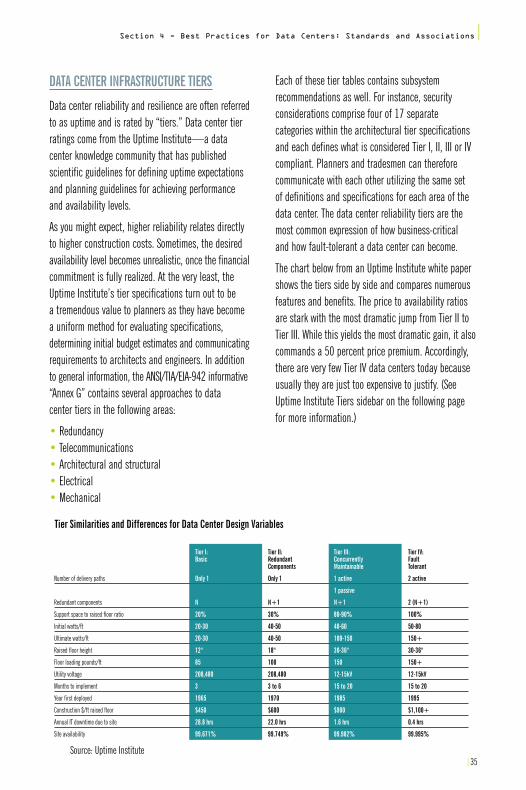
Source: Uptime Institute|35
Section 4 - Best Practices for Data Centers: Standards and Associations|
DATA CENTER INFRASTRUCTURE TIERS
Data center reliability and resilience are often referredto as uptime and is rated by “tiers.” Data center tierratings come from the Uptime Institute—a data center knowledge community that has published scientific guidelines for defining uptime expectationsand planning guidelines for achieving performance and availability levels.
As you might expect, higher reliability relates directlyto higher construction costs. Sometimes, the desiredavailability level becomes unrealistic, once the financialcommitment is fully realized. At the very least, theUptime Institute’s tier specifications turn out to be a tremendous value to planners as they have becomea uniform method for evaluating specifications, determining initial budget estimates and communicatingrequirements to architects and engineers. In additionto general information, the ANSI/TIA/EIA-942 informative“Annex G” contains several approaches to data center tiers in the following areas:
• Redundancy• Telecommunications• Architectural and structural• Electrical• Mechanical
Each of these tier tables contains subsystem recommendations as well. For instance, security considerations comprise four of 17 separate categories within the architectural tier specificationsand each defines what is considered Tier I, II, III or IVcompliant. Planners and tradesmen can thereforecommunicate with each other utilizing the same set of definitions and specifications for each area of thedata center. The data center reliability tiers are themost common expression of how business-critical and how fault-tolerant a data center can become.
The chart below from an Uptime Institute white papershows the tiers side by side and compares numerousfeatures and benefits. The price to availability ratiosare stark with the most dramatic jump from Tier II toTier III. While this yields the most dramatic gain, it alsocommands a 50 percent price premium. Accordingly,there are very few Tier IV data centers today becauseusually they are just too expensive to justify. (SeeUptime Institute Tiers sidebar on the following page for more information.)
Tier I:Basic
Only 1
N
20%
20-30
20-30
12"
85
208,480
3
1965
$450
28.8 hrs
99.671%
Number of delivery paths
Redundant components
Support space to raised floor ratio
Initial watts/ft
Ultimate watts/ft
Raised floor height
Floor loading pounds/ft
Utility voltage
Months to implement
Year first deployed
Construction $/ft raised floor
Annual IT downtime due to site
Site availability
Tier II:Redundant Components
Only 1
N+1
30%
40-50
40-50
18"
100
208,480
3 to 6
1970
$600
22.0 hrs
99.749%
Tier III:ConcurrentlyMaintainable
1 active
1 passive
N+1
80-90%
40-60
100-150
30-36"
150
12-15kV
15 to 20
1985
$900
1.6 hrs
99.982%
Tier IV:Fault Tolerant
2 active
2 (N+1)
100%
50-80
150+
30-36"
150+
12-15kV
15 to 20
1995
$1,100+
0.4 hrs
99.995%
Tier Similarities and Differences for Data Center Design Variables

36 |
|Section 4 - Best Practices for Data Centers: Standards and Associations
UPTIME INSTITUTE TIERS
Tier I (Basic) (N*):Need single path for power and cooling distribution,no redundant components, 99.671 percent availability.Susceptible to disruptions from both planned andunplanned activity. UPS or generator is a single-modulesystem with many single points of failure. To performannual preventive maintenance and repair work, theinfrastructure must be completely shut down.
Tier II (Redundant Components) (N+1):“Need plus one” single path for power and cooling distribution, redundant components, slightly less susceptible to disruptions–99.749 percent availability.Maintenance of the critical power path and other parts of the site infrastructure require a processing shutdown.
Tier III (Concurrently Maintainable) (N+1):Multiple power and cooling distribution paths, but onlyone path active. Allows for any planned site infrastructureactivity without disrupting the computer hardwareoperations. Contains redundant components that are concurrently maintainable with 99.982 percentavailability. Tier III sites are often designed to beupgraded to Tier IV sites when cost allows.
Tier IV (Fault Tolerant) 2(N+1):S+S* multiple active power and cooling distributionpaths, redundant components, 99.995 percent availability. The site infrastructure is able to sustain at least one worst-case unplanned failure or event withno critical load impact. S+S=System+System–twoseparate UPS systems in which each system has N+1redundancy. This requires all computer hardware tohave dual power inputs. It supports high availability ITconcepts that employ CPU clustering, RAID and DASDstorage methods, and redundant communications toachieve high reliability, availability and serviceability.
* Please note: the Uptime Institute defines “N” as“Need” and “S” as “System.”
Cabling Choices in the Data CenterThe TIA is a North American standards body that oftenworks in tandem with the IEEE as new networking standards are being explored. The International Organization for Standardization (ISO) is also expecting to develop new cabling standards. The use of 10 GigabitEthernet will see implementation in data centers wherehigh bandwidth between server farms and storagedevices is needed. Existing high-performance connectivitysolutions in the data center such as Infiniband and Fibre Channel may be displaced by or augmented withEthernet. The 10 Gigabit Ethernet standards have beendeveloped by IEEE, ISO and TIA to address the need formanageable, standardized connectivity solutions indata centers and ultimately in commercial businessenvironments. IEEE has defined four twisted-paircabling system models for 10 Gigabit Ethernet datalinks. The first model utilizes fully screened andshielded cable–ISO Class F cable (Category 7) toachieve 100 m distances at up to 600 MHz. Much like Class F cabling, Models 2 and 3 will also support100-meter reach. The main difference is that models 2 and 3 use twisted-pair cabling media, the TIA Augmented Category 6 and ISO Class EA, respectively.Model 4 utilizes ISO Class E cable (TIA Category 6),which operates at 250 MHz and may achieve up to 55 m depending on the grade of the cable channel,installation technique and environmental conditions.The standards organizations realize there is often aninstalled base investment within existing facilities.They frequently attempt to protect a customer’sinvestment with backward compatibility. Model 4attempts to mitigate performance issues that mayarise when utilizing Category 6/ISO Class E infrastructure to support 10 Gigabit Ethernet.

|37
Section 4 - Best Practices for Data Centers: Standards and Associations|
Alien crosstalk (ANEXT and AFEXT) presents a significantchallenge to cable manufacturers designing for 10 Gigabit speeds. Alien crosstalk occurs through theelectromagnetic signal coupling of pairs in adjacentfour-pair cables. Today’s innovative cable constructionhas shown that ANEXT can be minimized up to 100 mdistances at frequencies as high as 500 MHz. This accomplishment allows data centers and otherhigh-speed infrastructures to deploy 10 Gigabit copperdata paths utilizing less expensive and easy-to-usetwisted pair, in addition to fiber links.
In the cabling standards world of TIA, two projectscomplement the work of the IEEE. The ANSI/TIA-TSB-155project has defined the channel and link specifications for 10 Gigabit Ethernet over the current TIA Category 6 standard. Most standards bodies will always do what they can to prevent product obsolescence within the installed base ofcommercial customers. This is taken very seriouslybecause of the higher cost of replacing material within walls, between floors and between buildings.Testing procedures for measurement of the aliencrosstalk effects between all pairs in adjacent cables(power sum alien near end crosstalk or PSANEXT) is outlined in this Technical Service Bulletin (TSB-155).The goal of the TSB-155 is to protect customer investment in an installed Category 6 cabling infrastructure. Additionally, TIA has considered and recommends mitigation procedures for reducing thelevel of alien crosstalk Category cables if it is found at significant levels in field testing.
The other committee, ANSI/TIA-568-B.2-Ad10, createdan addendum to the ANSI/TIA-568-B.2 standard todevelop what is referred to as “Augmented Category 6.”Augmented means that standard Category 6 performancewas “pushed” beyond its initial 250 MHz range to 500 MHz.This specification is commonly referred to as 10GBASE-T (10 Gigabit Baseband over Twisted Pair).
The ISO specification for 10 Gigabit Ethernet over 100-ohm twisted-pair copper (Class EA) is currentlymore stringent than the current draft of the TIA Augmented Category 6 specification. In the InfrastructureSolutions Lab, Anixter verifies that all of its supported10GBASE-T cabling products are compliant with the latest ISO draft standards. This approach offers Anixtercustomers more versatility and a higher performancethreshold for their networks. Additionally, ensuringextra “headroom” in data networks is a product anddesign philosophy that Anixter has always recommended.Testing all cabling channel products to the higher standard ensures all the necessary characteristics for data center infrastructure: quality, reliability, availability and performance. Within the International standards organizations, a technicalequivalent to TSB-155 has been developed under the reference IEC24750.
Another 10 Gigabit Ethernet copper media option indata centers is called 10GBASE-CX4. This option isdesigned to be used within a rack or cabinet to supportserver clusters. Beyond this specialized scenario, theuse is limited, as the maximum distance supported isonly 15 meters and the physical connector interfaceused for 10GBASE-CX4 is not based on the more commonly deployed RJ45 physical interconnect. IEEE also included an option called “short reach” within their 802.3an 10 Gigabit Ethernet standard. It essentially allows ports on a switch or the Ethernetadapter of the server to power down elements of itsinternal circuitry if they sense a short distance (lessthan 30 meters). However, the short reach modeoption will only operate using Augmented Category 6or ISO Class EA grade cabling. Augmented Category 6may be used in this instance and may eclipse the useof 10GBASE-CX4 in the process, as these cables are anexpensive twinaxial construction and require the useof a special connector. Standard Category 6/ISO Class Emay not be used in this application, as the electricalcharacteristics are not suitable.

38 |
|Section 4 - Best Practices for Data Centers: Standards and Associations
PROTECTION OF DATA CENTER ASSETS
Availability and longevity of data centers can be compromised by several factors such as fire, vandalismor even terrorism. The ANSI/TIA/EIA-942 standard provides information to planners regarding the protection of data center assets whether by means of physical security or fire prevention. It also recognizes the importance of providing manageableaccess control to data center facilities and monitoringof who is there and who is doing what. According toDuPont, approximately 323 non-residential fires andover seven million dollars of property damage occureach day. While improvements to fire safety practices,equipment and building materials can save lives, they can also protect assets.
Potential asset losses in data centers can create concern. The cost of downtime and computer equipmentlosses hit the top of the list of these concerns. Mostdata centers are protected by sophisticated air-samplingsmoke and fire monitoring systems, pre-action, dry-pipesprinkler systems and clean agent inert gas systems.Tiny smoke particles can become highly damaging to computer hard drives and storage systems so fire and smoke prevention is a key element of data center design. The informative “Annex G” of the ANSI/TIA/EIA-942 standard lists many guidelinesand practical suggestions.
ENVIRONMENTAL MONITORING SOLUTIONSANSI/TIA/EIA-942 specifies a normal data center environmental operating range between 68 and 77 degrees Fahrenheit (20-25 degrees Celsius) with a sustained humidity level of 40 to 55 percent. Also, anychange in the environment should never exceed ninedegrees per hour. Humidity control is a key objectivefor minimizing static charge buildup on equipment and infrastructure. Accidental static discharge can produce high voltages that can seriously damage sensitive microprocessors.
Additional challenges to uptime can present themselvesas a result of human error, power spikes or even sabotage. The TIA data center standard addressessecurity concerns and recommends video surveillanceof parking lots, perimeters, support equipment roomsand of course, the computer room itself. Some datacenter planners and operators actually run all of theircabling overhead not only to simplify connectivitychanges, but to constantly monitor and record anyphysical work or changes done to fiber or copper infrastructure. This approach allows the Network Operations Center to quickly find or rule out possibilitieswhen troubleshooting service disruptions or outages.Additionally, there are many ways to control data center access and the ANSI/TIA/EIA-942 standard contains recommendations and security tiers to aid in upfront planning.
In addition to protecting valuable computer equipment from smoke andfire damage, temperature and humidityare key factors to consider when uptimeand equipment longevity are strongobjectives as they are in the data center.

|39
Section 4 - Best Practices for Data Centers: Standards and Associations|
DATA CENTER STANDARDS SUMMARY
ANSI/TIA/EIA-942 is a comprehensive document that provides data center planners with guidelines fordesign, construction and expansion within telecom,electrical, architectural, mechanical and securityareas. It provides mandatory infrastructure standardsand informational guidelines presented by levels ofperformance and availability known as “tiers.” The ANSI/TIA/EIA-942 is an excellent vehicle for communication among data center professionals and provides tremendous value by addressing manypreviously disparate topics in one document.
The ANSI/TIA/EIA-942 is a standard that gives guidelinesfor the design and installation of a data center. The standard specifies:
• Cabling design• Network design• Facilities design• Informative annexes containing “best practices”
and availability requirements• Spaces• Pathways• Racks/cabinets.
This is the base standard you will want to familiarizeyourself with so you will know important informationincluding the basic elements of a data center cablingplant or the four tiers of data center redundancy.Other standards to reference for products in your data center include the following.
IEEE 802.3an (10GBASE-T TASK FORCE)
The IEEE 802.3 family of standards deals with Ethernet.802.3an specifically deals with 10 Gigabit per secondEthernet or 10GBASE-T. The standard tells the manufacturers how to build 10 Gigabit Ethernet equipment, and it also gives recommendations for thecabling required to run 10 Gigabit Ethernet. It specifically mentions ANSI/TIA-568B.2 (ad10) and ISO Class EA.
ANSI/TIA-568B.2 (AD10) – AUGMENTED CATEGORY 6 TRANSMISSION PERFORMANCE AND ISO 11801 CLASS EA
Both of these standards are cable, component andchannel standards for 10 Gigabit Ethernet. Running 10 Gigabit Ethernet over copper requires higher bandwidths and uses all four pairs at once. This has introduced new issues such as alien crosstalk, which istaken into account in the new standards. An importantnote about the ISO standards is that its proposedstandard for cabling infrastructure for 10 Gigabit Ethernet is more stringent than the TIAs. Anixter’s Lab tests to the tougher ISO requirements.
IEEE 802.3af AND 802.3atPOWER OVER ETHERNET STANDARDS
These standards allow for running power over thesame cabling plant as data to support IP phones,WLAN access points and many other devices. 802.3af isthe current standard that allows for up to 12.95 wattsof power at the end device. The proposed 802.3atstandard would raise that power to a minimum of 30 watts and up to 70 watts. This is important forpowering devices like motors for Pan/Tilt/Zoom (PTZ) cameras.

40 |
|Section 4 - Best Practices for Data Centers: Standards and Associations
ANSI/TIA-569-BCOMMERCIAL BUILDING STANDARD FOR TELECOMMUNICATIONS PATHWAYS AND SPACES
A lot of time is spent considering the electronics andcabling that go in a data center. It is just as importantto spend time designing the pathways and spaces forthat equipment and cabling. The pathways and spacesof a data center will outlast the cabling and equipment.As a result, much thought must go into preparing themfor future technologies. This standard defines andspecifies areas such as service entrance pathways and firestops. In this standard, you can find discussions on the lighting, HVAC and access to the telecommunications closet. You will even find the maximum amount of dust that can be found in the air within the data center.
ANSI/TIA-606-A ADMINISTRATION STANDARD FOR THE TELECOMMUNICATIONS INFRASTRUCTURE OF COMMERCIAL BUILDINGS
Moves, adds and changes are constant in any communications system. The data center is at the center of all of these moves. The key part of this standard is identification and labeling. Standard labeling will make it easy for any technician to identify each part of the system. The standard alsocovers elements such as records and work orders.
ANSI-J-STD-607-A-2002COMMERCIAL BUILDING GROUNDING AND BONDING REQUIREMENTS FOR TELECOMMUNICATIONS
Data centers are collections of very expensive and complicated electronic devices. These systemsrequire a reliable electrical ground-reference potential. Grounding by attachment to the nearestpiece of iron pipe is no longer satisfactory to provide ground reference for sophisticated active electronics systems. This standard shows how to properly ground data center equipment to provide personnel safety and a noise resistant electronic environment. Please reference EN50130 for groundingand bonding in Europe. Details can be found the Anixter’s European Standards Reference Guide.
For more detailed information on networking standards, orderAnixter’s Standards ReferenceGuide at anixter.com/literature(North American or European version).

|41
Section 4 - Best Practices for Data Centers: Standards and Associations|
For Canadian installations, the Canadian ElectricalCode (CSA C22.1) applies rather than the NEC (NFPA70). The Codes of both countries require the use ofspecific UL Listed or CSA certified cables in each application. For example, cables installed in cabletrays must meet certain fire test requirements to minimize fire propagation in the event of a fire. One power cable type frequently used in tray in U.S. data centers is NEC type RHH (per UL 44) with a “For CT Use” rating. This optional rating is based primarily on fire test performance and is one of manyspecific ratings that permit a cable to be installed in tray. Other optional ratings include ST1 (limitedsmoke) and LS (low smoke) ratings that verify a cablemeets specific smoke emission requirements in UL 44.
These ratings are not required by code. Data centerpower cables are also sometimes known as “KS spec”cables, which is a reference to central office powercable standards that have been in use for roughly halfa century. KS power cable specifications are owned by Tyco Electronics Power Systems and include cable standards such as KS-24194™ and KS-22641™.
Other power cable and power cable installation standards often applicable to data centers include NEMA WC 70 (ICEA S-95-658), Telcordia GR-347-CORE, Telcordia GR-1275-CORE, ANSI/TIA/EIA-942 and ANSI-J-STD-607-A-2002. For European power cablerequirements, please refer to page 22 of this guide.
For data centers located in the U.S., power cables and their installation mustusually comply with the NEC as well as any applicable state or local codes.Although the NEC does not officially apply to installations of communicationsequipment under the exclusive control of communications utilities, virtuallyall utilities choose to comply to reduce their potential liability as well as theirinsurance premiums.
STANDARDS FOR POWER CABLES

42 |
|Section 4 - Best Practices for Data Centers: Standards and Associations
DATA CENTER ASSOCIATIONS
The Uptime Institute A source of information for design, installation andoperation of a data center is the Uptime Institute. The Uptime Institute is a pioneer in the research andeducation of best practices for data center uptimereliability and improving uptime management in datacenter facilities and Information Technology organizations. The Institute maintains knowledge communities including the renowned Site Uptime Network®—a member community of Fortune 500companies that learn from one another and throughInstitute-sponsored meetings and tours, research,benchmarking best practices, uptime metrics, andabnormal incidents. The Institute also offers publiceducational seminars, sponsored research and white papers on IT and facilities site infrastructure,uptime management including high density coolingperformance, cold aisle/hot aisle design, Tier I, II, IIIand IV classifications, facility downtime, planning and critical physical layer design.
For more information visit www.uptimeinstitute.org.
AFCOM AFCOM is a leading association for data center professionals, offering services to help support the management of data centers around the world.AFCOM was established in 1980 to offer data centermanagers the latest information and technology they need through annual conferences, published magazines, research and hotline services, industryalliances and more.
AFCOM is one of the most respected names in the data center industry, due in large part to its exceptionalservices and resources. The association’s membershipincludes data center managers, MIS directors, CIOsand other IT professionals from Fortune 500 companies.
For more information visit www.afcom.com.

|43
Section 4 - Best Practices for Data Centers: Standards and Associations|
“GREEN” DATA CENTERS AND BUILDINGS
Green initiatives around the design and constructionof buildings and data centers have been in the news,papers, and magazines for the last 10 years, but haverecently received more visibility. The U.S. Governmentis also increasingly getting more involved with tryingto increase the energy efficiency for data centers andcomputing technology. In fact, in July of 2006, the U.S. House of Representatives approved legislationinstructing Americans to “give high priority to energyefficiency as a factor in determining best value andperformance for purchases of computer services. Higher efficiency in servers not only reduces electricitybills, but it also offers lower cooling costs.” (Source:cnetnews.com.) Furthermore, the EPA is analyzing thebenefits associated with energy efficient computing.The US Department of Energy states that 75 percent of the total cost of ownership (TCO) for data centers is related to power consumption.
LEED (LEADERSHIP IN ENERGY ANDENVIRONMENTAL DESIGN)
Other organizations such as LEED have been aroundsince 1999 and are increasing in popularity as well.LEED is a voluntary standard created by members of theU.S. Green Building Council for developing buildings thatare environmentally responsible and are a healthy placeto live and work. A LEED certification for a projectillustrates a dedication to sustainability and energyefficiency. Acceptance of the LEED Green Building Rating System has grown considerably over the past10 years and more jurisdictions and governmentalagencies are requiring LEED certification for new projects. A building can earn points toward one of four levels of LEED certification through such projectcomponents as site selection, architecture andmechanical systems. The LEED certification also looks at other variables such as optimized energy performance, construction waste management, building automation systems (BAS), controllability and innovative design. More information on the LEEDcertification can be obtained by a LEED accreditedprofessional or by visiting www.usgbc.org / leed.
Earning Points Toward LEED CertificationEarning points toward the LEED certification can be difficult and proper innovative input from all design and construction entities should be considered.The data design and build contractor can easily generate several points towardproject certification. For example, through efficient design of the mechanical,electrical and lighting systems, energy efficient buildings can reduce energycoded requirements. If the building’s energy use is less than the energy code by a minimum of 10.5 percent for new buildings and 3.5 percent for retrofit buildings, the project can obtain LEED points.
Please note: the LEED certification program does notapply in Europe at the present time.

44 |
|Section 4 - Best Practices for Data Centers: Standards and Associations
SUMMARY
When it comes to the communications infrastructure,Anixter can make several specific recommendations.While the ANSI/TIA/EIA-942 standard for data centersspecifies a copper minimum of Category 6 cabling,Anixter recommends cabling to support 10 Gigabit Ethernet in new data centers and during data centerexpansion. At minimum, a Category 6A construction is needed to provide bandwidth in the 500 MHz rangewith proven control of alien crosstalk.
Anixter continues to recommend fiber in all backbonesincluding the data center. Laser-optimized, 50-micronis the fiber of choice—again to ensure the data center is ready whenever and wherever 10 Gigabit Ethernet becomes a requirement. Additionally, limited combustible cable has strong merit in limitingloss—both of life and property and may be a requirement when the NEC is updated in 2008.
It pays to use the latest security and monitoring technology to protect assets and uptime from internaland external threats. Video surveillance, access control and environmental monitoring are all areaswhere Anixter can provide its product expertise during the data center design and upgrade process.
Anixter understands the challenges facing today’s data center professionals and embraces standardssuch as ANSI/TIA/EIA-942 whose goal is to provide acomprehensive roadmap for success. Anixter supportsdata center customers in achieving their goals ofavailability, reliability and operational efficiency.

|45
Section 5 - Key Considerations for Deploying Data Center Solutions|
SECTION 5Key Considerations for Deploying Data Center Solutions
Supply Chain Services and Data Center 46
Anixters Supply Chain Services in Action 50
Material Management Matters 51

46 |
|Section 5 - Key Considerations for Deploying Data Center Solutions
SUPPLY CHAIN SERVICES AND DATA CENTERS
The foundation to an efficient data center deploymentproject is having a distribution network that you can leverage for product inventory and coordinating deliveries with installation resources. Data centersrequire materials from multiple manufacturers to arrive at the right place, at the right time, to be installed on-time and within budget.
Fundamental distribution services should include:
• The ability to view and allocate inventory in any warehouse globally
• A significant investment in a diverse breadth of inventory
• IT systems that provide customers real-time information
• Predictable delivery times and processes to help you plan your projects.
Anixter takes fundamental distribution a step furtherby applying “best practices” of supply chain principles to the industry and the reality we face everyday with technology deployments.
Our common goal is to help you:
• Reduce costs• Save time• Improve productivity• Improve efficiency• Enhance financial performance• Mitigate risk• Create scalable and repeatable services.
While a significant amount of time is spent on technological products, we believe that an additionalconversation needs to happen regarding the processside of the project. Identifying the fixed costs as wellas process inefficiencies associated with materialmanagement is important. Together, we can identifythe challenges in material management.
“Poor supply chain design regularly increases project costs by 10 percent ormore, and project duration might be similarly affected.”–University of Florida
READY! SM Deployment Services by Anixter maps our distribution and Supply Chain Services to theconstruction or deployment process of any technology project. We combine sourcing, inventorymanagement, kitting, labeling, packaging and deployment services to simplify and address thematerial management challenges at the job site(s). READY! Deployment Services by Anixter will help you improve the speed to deployment, lower your total cost of deployment and ensure product specifications are delivered as planned.

|47
Section 5 - Key Considerations for Deploying Data Center Solutions|
Challenges in Technology Deployments:Managing Multiple Sources
and Delivery Points
This model represents typical challenges we see in many data center deployments. These challenges include:
• Multiple OEMs are part of the build-out
• Multiple ways to get product to the job site
• Multiple aggregators (subcontractors, integrators, distributors, etc.) are involved.
The model incurs stress when you add more components(manufacturers, trades or sites). A complex situationlike this one cannot seamlessly scale to meet the project demands. In fact, if the project demandsincrease, bottlenecks in service, support and expense become evident.
Every line on this diagram represents a point of risk:expense, coordination and/or failure. Anixter’s Supply Chain Services minimizes the risk involved withtechnology deployments by coming up with a plan to:
• Deliver the right products, to the right place, with the right quantity, in the right condition, at the right time, every time
• Efficiently coordinate the processes: materials, manufacturers and trades
• Maximize installation productivity while minimizing delay/wait time
• Eliminate disruption to regular operations.
Anixter’sSupply Chain Solutions:
Minimize Process and Cost
Material management matters. To improve on-timecompletion of the project, it is important to have an effective material management strategy. Putting a supply chain partner in the middle allows you toeffectively manage the materials for one or multipleprojects and scale to meet demand. A supply chainpartner enables you to focus on your core competency.
Anixter can help you develop a well-defined program to minimize added costs while maximizing efficiencyand reducing risk. We will work with you to completethe following:
• Evaluate all processes involved with material procurement, inventory management and project deployment
• Streamline order entry, material management, vendor consolidation, deliveries and material management at the job site
• Create a customized supply chain solution for your data center project
MANUFACTURERS
SITES
INTEGRATORCONTRACTOR DISTRIBUTOR
MANUFACTURERS
SITES

48 |
|Section 5 - Key Considerations for Deploying Data Center Solutions
The Supply Chain Model: Scalable and Repeatable
The definition of “supply chain” is the efficient flow of goods, services and related information from the point of origin to the point of consumption.
To define the supply chain solutionfor technology deployments, we recommend you define key steps in the process. The baseline modelabove illustrates six key componentsa supply chain partner shouldaddress when building an effectivesolution for you. To scale to the project’s demands, the model needsto be addressed as a whole, not justindividual components.

|49
Section 5 - Key Considerations for Deploying Data Center Solutions|
The following information is a break-down of Anixter’s Supply Chain Services model.
Sourcing It is important to identify the product specifications at the beginning. It is just as important to identify allthe products for each system that you will need for theproject. Anixter has product and technical expertise to help during this step of the process to support a breadth of OEM supplier relationships. One of thequestions during the sourcing process is who will beresponsible for procuring the material? Our experienceis that the answer will include the data contractor/integrator, electrical contractor, security integrator andend-user. Coordination of deliveries to these buyinggroups will be handled at the deployment phase of the supply chain model.
LogisticsThis step in the process is primarily concerned with lead time management of the products into our distribution facility. As with any project, there are multiple manufacturers and products. One of Anixter’s core competencies is to effectively managethe volume of work associated with inbound logisticsto our warehouse, making sure we have the product in stock when and where you need it.
Inventory ManagementThis is the heartbeat of the supply chain offering. Anixter’s ability to manage piece part detail and inventory is the basis of our fundamental distributionmodel. Anixter currently stocks more than $1 billion of products throughout our warehouse network. Theinventory management system throughout our warehousenetwork is a single platform and can be customized to catalog the products specific to your project. Anixter’s investment allows our customers to leverageour experience to create a scalable, repeatable, cost-effective solution.
Product Enhancement and PackagingHere is the question: What can we do at the warehouse(prior to shipment) that can make material managementat the job site easier and more cost effective? Anixterservices offered at the warehouse include kitting, pre-assembly, labeling, special packaging requirements,etc. We can work with you to define your scope of work.
DeploymentThe product has been sourced, inventoried and packaged. Now it is time to assess the deploymentschedule. What are the delivery requirements? How will we build the piece of the model to scale to the project demands and support multiple trades?Anixter can leverage its current relationships withtransportation companies to meet your expectations.
eBusinessEvery process needs visibility. We can provide you with a customer view of key events in the supply chainmodel. Think of this as your view into our warehousenetwork, inventory and shipping information. Additionally, anything on our system can be “mined”from the database to provide you key measurementsand reports.

50 |
|Section 5 - Key Considerations for Deploying Data Center Solutions
ANIXTER’S SUPPLY CHAIN SERVICES IN ACTION
When a large financial institution was refreshing itsdata center infrastructure, it built a plan to completethe deployment in three specific phases. The projectrequired four different cabinet configurations for each phase over a 12-month period.
Project managers realized that material availabilitywas critical to a successful installation; prior experience proved that running out of materials (stock-outs) caused delays and that productivity wasreduced when installers were missing components.This effect (called “go backs”) added unproductivelabor hours and had the potential to delay the completion of each phase.
Anixter was invited to participate in the project as a supply chain partner. After discussing the project’s comprehensive bill of materials, timeline and installation procedures, Anixter developed a supply chain solution that would support the installation process in the most effective way.
Designs were supplied for each type of cabinetdepending on the equipment to be housed in it—servers, switching gear, and copper and fiber MDFs.Each cabinet had a specific bill of materials anddetailed plans on how the product was to be mountedin the cabinets. Anixter created specific part numbersfor each cabinet type to ensure the corporate specification and streamline the ordering process.
The following is an account of each step in the supplychain process and how we built the final solution forthe customer
SourcingAnixter stocked the majority of the products specified. However, the customer asked us to include some products that it already owned. We received andstored the customer-owned material in our warehouse.We also created a unique part number to identify eachtype of cabinet as one all-inclusive part number,including the Anixter-provided and customer-ownedmaterial. Purchasing one part number for a completecabinet instead of placing orders for multiple productsfrom many sources reduced personnel and simplifiedprocesses needed to manage the purchase orders.
LogisticsThe project’s success relied on timely delivery of allmaterials to the job site according to the project’sphases. Anixter took control of managing the lead timesof the multiple manufacturers specified for the project.Our job was to make sure everything was in stock, and not delay the down stream deployment of theseproduct solutions.
Product Enhancement and PackagingTo maximize efficiency, we identified tasks that could be done at the warehouse prior to shipping the product. Cabinets were preassembled with patch panels, wire management, power strips and otherequipment mounted according to the customer’s specifications. Additionally, kits with all necessarycomponents were also created and included in thesame shipment.
All components were packed together, color-coded and clearly labeled to ensure that the material waseasy to identify at the job site.

|51
Section 5 - Key Considerations for Deploying Data Center Solutions|
DeploymentBecause delivery took place in the city, a transportationsolution was carefully chosen to meet specific deliverytimes. The material then could be unloaded at theavailable dock and taken via the freight elevatordirectly to the specific point of installation.
To oversee the process and avoid delays, we assigneda Supply Chain Program Management Specialist to theproject. The specialist coordinates efforts with thecontractor’s project management team and differentsuppliers to make sure all materials arrived as definedto the job site according to schedule.
KEY BENEFITS TO THE CUSTOMER
• Anixter’s Supply Chain Services helped the customer,consultants and contractors reduce the overall cost of deployment and deliver a project on timeand on budget.
• Consolidating purchases and aggregating all products into one unique part number simplifiedthe ordering, tracking and management process.
• Having Anixter manage the lead times and storematerials in one warehouse until it was needed for installation reduced the upfront inventoryinvestment needed by the customer.
• Anixter’s logistics expertise in coordinating deliveries, even in challenging conditions, helped keep the project on track.
• Product preassembly and whole order delivery minimized the need for storage and staging spaceat the data center and also allowed the contractorto dedicate highly skilled personnel to focus on his primary mission of building the infrastructurefor the data center without increasing the overallcost to the customer.
Thanks to an efficient and predictable supply chain,all three phases of the project were completed according to schedule and budget.
MATERIAL MANAGEMENT MATTERS
Addressing material management and its affect on the supply chain can be the fundamental difference of success for your project. Anixter understands that there are many challenges with building a data center including selecting the right technology, properlydesigning the data center, and determining the right contractors and integrators to complete the installation.
As you design your data center, Anixter can help youlook at the deployment process to maximize yourinstallation and on-time completion of the project. We do this by addressing the material managementchallenges at the job site before the material arrives.
As you look at your data center project deployment, askyourself these questions regarding Supply Chain Services:
• What potential delays in your project have you identified with regards to material management?
• Do you anticipate an acceleration of time frame or anincrease of scope in work for the data center build-out?
• What is the plan to deliver material to the job sitefor the IT and security infrastructure solutions andthe contractors/integrators who will install them?
• What is your plan to manage the lead times for all the products involved and how will you makesure they are delivered on time?
• What sections of the data center could you “kit” orpreassemble prior to delivery that would minimizethe risk of the material at the job site? These sectionscould include server cabinets, KVM cabinets, MDF copper, MDF fiber, switch cabinets, etc.
Anixter’s Supply Chain Services can be modified to your specific project and can scale to meet your project demands. Whether you are building one largedata center or consolidating multiple data centers into a select few, we can create a process togetherthat will allow you to deploy an effective supply chain solution.

52 |
|Appendix - About Anixter
APPENDIXAbout Anixter
The Anixter Difference 53
Our Global Capabilities 53
Our Products 53
Our Supply Chain Services 54
Our Technical Expertise 55
The Anixter Infrastructure Solutions Lab 55
Anixter University 58

|53
Appendix - About Anixter|
THE ANIXTER DIFFERENCE
We are proud to serve more than 100,000 customers across 49 countries every day with our world-class inventory, global capabilities, technical expertise and Supply Chain Services. Our three specialized salesforces focus on Enterprise Cabling & Security Solutions,Electrical and Electronic Wire & Cable and Fasteners.
• We stock more than 400,000 items from the world’s premier manufacturers and move them cost effectively through our global distribution network that encompasses more than 6 millionsquare feet of distribution space.
• We view technical know-how as an essential part of our value to our customer. Whether you are dealing with our Enterprise Cabling & Security Solutions, Electrical and Electronic Wire & Cable, orour Fasteners division, you can count on Anixter forreliable up-to-date technical advice and assistance.
• With a wide variety of Supply Chain Services to choose from, we provide our customers the opportunity to save money by increasing their ability to be efficient and to avoid costly delays.
OUR GLOBAL CAPABILITIES
We are very proud of the quality products we distribute(over $1 billion of inventory from best of class manufacturers), but the reason our customers counton us day in and day out is not just about world-class,quality products. Our customers know they can counton Anixter to deliver consistent, superior service andsupport around the world. And when we say we areglobal, we mean it. We do not just ship products from the U.S. to various countries, we stock inventoryin each country and we are specialists at movinginventory across borders efficiently and cost effectively. Anixter is located in 49 countries aroundthe globe, and our sales specialists in-country arefamiliar with the trends and needs in the local market, as well as the local currency, standards and customs. We speak 30 different languages toserve our customers’ diverse needs.
OUR PRODUCTS
It seems simple enough: you need something, you call a distributor and buy it. Unfortunately, nothing is really that simple. In the real world, there are complicated systems, small parts, and constantly changing technical developments and requirements. Just determining what you need can be an all-consuming process, one that is only aggravated by hard to find or out of stock items. Missing a crucial component can significantly add costs and delays to your projects.
54 |
|Appendix - About Anixter
At Anixter, we take the worry out of Just-in-Time productavailability. We maintain more than $1 billion in ourglobal inventory, and the product expertise you need to make sure you get the right product, when and whereyou need it.
Anixter is the distributor to call on if you need products and solutions for:
• Network cabling (copper and fiber)
• Security (video surveillance, access control)
• Electrical wire and cable (power cable)
• Electronic wire and cable (coax, multi-pair, multi-conductor cable, etc.)
• Networking, wireless, and voice electronics
• Fasteners and other small components (“C” Class).
OUR SUPPLY CHAIN SERVICES
The purchase price of a product is not the only place to look to reduce costs in your business. Effective management of your supply chain process will give you the greatest cost benefits.
Anixter’s Supply Chain Services were developed to respond to our customers’ needs for a businesspartner, not simply a product provider. To service each customer’s unique needs, our Supply Chain Services isfocused on the complete supply chain process– fromsourcing to delivery–rather than just the product purchase.
OUR SUPPLY CHAIN SERVICES OFFERING
Our modular service approach allows us to customize our Supply Chain Services solution to fit your specific needs.
• eBusiness Solutions: Anixter’s superior eBusiness capabilities are available for integration with your own supply chain systems, to provide real-time transactions and information and unmatched visibility to all aspects of the supply chain.
• Sourcing: Our product knowledge and manufacturer management services can reduce the time andresources you spend while we secure the products you need.
• Logistics: Your material handling and transportation management responsibilities can be optimized with our logistics services.
• Inventory Management: Our Supply Chain Services customers realize a reduction in investment, space and personnel needed for receiving, storing and managing inventory.
• Product Enhancement and Packaging:Maximize the use of specialized labor by eliminating product preparation and non-essential, on-site assembly.
• Deployment: We coordinate all materials and enhancement processes for on-time delivery in one or multiple locations, to let you focus on your core business.

|55
Appendix - About Anixter|
OUR TECHNICAL EXPERTISE
Across the world, we have more than 2,600 sales specialists who support our customers. We have three specialized sales forces that focus on enterprisecabling and security systems, electrical and electronicwire and cable, and fasteners. These sales specialistshave years of experience in specifying products and solutions for customers. Our salespeople are well trained to truly identify and understand yourneeds and requirements.
Anixter’s expert Systems Engineers (SEs) receive ongoing,extensive training about new products, technologies,applications and market trends. In addition, many of our SEs participate in local standards and industry committees and associations, which keeps them currenton the latest standards being introduced into the market. Anixter also employs over 135 RCDDs (Registered Communications Distribution Designer), thehighest networking infrastructure design certification.
In every part of our business, we welcome the opportunity to support our customers’ purchasing decisions. You can rely on our technical experts to keepyou current on the latest products, applications, industrytrends, standards and emerging technologies.
THE ANIXTER INFRASTRUCTURE SOLUTIONS LAB
Anixter’s Infrastructure Solutions Lab allows us toactively demonstrate the best practical technologysolutions from best in class manufacturers in the areas of enterprise cabling solutions, video securityand access control systems for our customers. Our mission for The Lab is simple—educate, demonstrate and evaluate.
• Educate customers on the latest security and networking best practices, standards and technologies being deployed in the networking and security market.
• Demonstrate the latest enterprise cabling and security solutions available from our manufacturer partners.
• Evaluate our network infrastructure and securitysolutions to ensure that our customers are selectingthe right systems for their specific needs.
We are continually testing products in our Lab to ensure:
• Quality products are recommended and delivered to our customers
• Consistency of performance across product lines and within systems
• Interoperability of products and systems to ensure customers can integrate systems and follow the trend toward convergence.
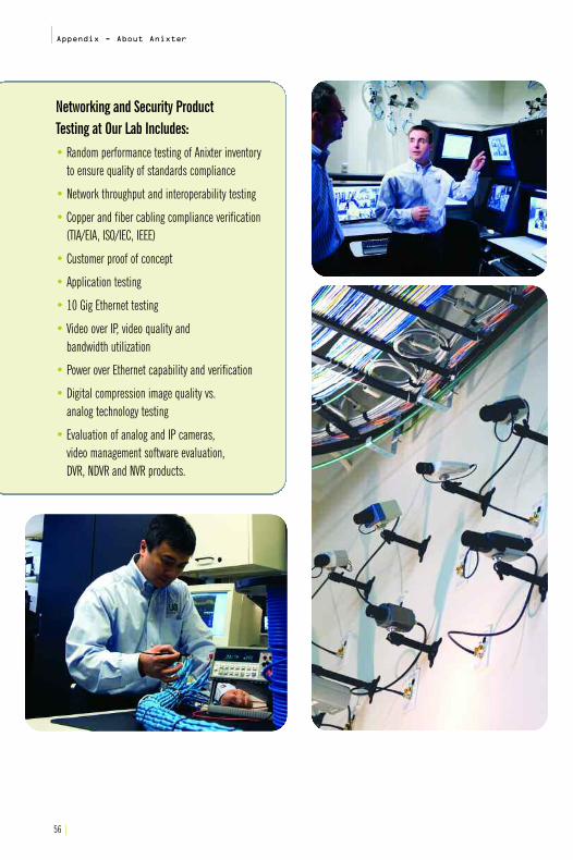
56 |
|Appendix - About Anixter
Networking and Security Product Testing at Our Lab Includes: • Random performance testing of Anixter inventory
to ensure quality of standards compliance
• Network throughput and interoperability testing
• Copper and fiber cabling compliance verification (TIA/EIA, ISO/IEC, IEEE)
• Customer proof of concept
• Application testing
• 10 Gig Ethernet testing
• Video over IP, video quality and bandwidth utilization
• Power over Ethernet capability and verification
• Digital compression image quality vs. analog technology testing
• Evaluation of analog and IP cameras, video management software evaluation, DVR, NDVR and NVR products.

Appendix - About Anixter|
You can find a comprehensive listing of these products in our printor online catalogs. Order a copy of our print catalogs at anixter.com/literature or visit our online catalog at anixter.com/catalog.
|57
Anixter can assist you with all of your infrastructure needs to support your data center solutions:
• Racks, cabinets and shelving products
• Pathway and raceway products
• Cable management products
• 10 Gigabit Ethernet and Augmented Category 6 cabling solutions
• Fiber solutions
• Pre-terminated fiber solutions
• Intelligent infrastructure solutions
• Power distribution products
• UPS and power protection products
• Intelligent power strips and rack/cabinet-mounted PDUs
• Environmental monitoring and management products
• KVM switches and console managers
• Patch cords and bulk cabling
• Grounding and bonding products
• Supplies (firestop, cable ties, consumables, etc.)
• Power cabling and accessories
• PoE devices (in IDF and telecom closet)
• Access control and surveillance systems and devices
• Test equipment
• Tools

58 |
|Appendix - About Anixter
Anixter's Data Center College (DCC) is a free andunique educational institution with a curriculumdesigned to create awareness and to provide general solutions for current and future data center infrastructure issues. Topics covered include10 Gigabit Ethernet, wireless, Power over Ethernet,thermal management, access control and video surveillance, just to name a few. The format for DCCbrings a comprehensive array of technical and informational courses directly to the customer's site.
Visit anixter.com/dcc to learn more about DCC or to register for a class.
Anixter University. Data Center College.

Anixter would like to acknowledge the following companies for their contributions,either directly or indirectly to this guide:
• Avocent• Corning Cable Systems• DuPont• iTracs• SYSTIMAX® Solutions
TrademarksIEEE 802.3afTM is a trademark of the Institute of Electrical and Electronics Engineers, Inc., (IEEE).
IEEE 802.3anTM is a trademark of the Institute of Electrical and Electronics Engineers, Inc., (IEEE).
Teflon® is a registered trademark of E.I. du Pont de Nemours and Company.
Anixter is a trademark of Anixter Inc.
KS-22641TM is a trademark of Tyco/Electronics Corp.
KS-24194TM is a trademark of Tyco/Electronics Corp.
LEED® is a registered trademark of the U.S. Green Building Council.
Site Uptime Network® is a registered trademark of The Uptime Institute
SYSTIMAX® Solutions is a registered trademark of SYSTIMAX Solutions
|59
Appendix - About Anixter|
Anixter is located in 249 cities in 49 countries.
See if Anixter islocated in a city
near you at the end of this guide.
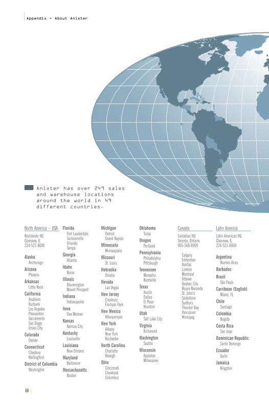
60 |
|Appendix - About Anixter
North America – USAWorldwide HQGlenview, IL224-521-8000
AlaskaAnchorage
ArizonaPhoenix
ArkansasLittle Rock
CaliforniaAnaheimBurbankLos AngelesPleasantonSacramentoSan DiegoUnion City
ColoradoDenver
ConnecticutCheshireWallingford
District of ColumbiaWashington
FloridaFort LauderdaleJacksonvilleOrlandoTampa`
GeorgiaAtlanta
IdahoBoise
IllinoisBloomingtonMount Prospect
IndianaIndianapolis
IowaDes Moines
KansasKansas City
KentuckyLouisville
LouisianaNew Orleans
MarylandBaltimore
MassachusettsBoston
MichiganDetroitGrand Rapids
MinnesotaMinneapolis
MissouriSt. Louis
NebraskaOmaha
NevadaLas Vegas
New JerseyCranburyFlorham Park
New MexicoAlbuquerque
New YorkAlbanyNew YorkRochester
North CarolinaCharlotteRaleigh
OhioCincinnatiClevelandColumbus
OklahomaTulsa
OregonPortland
PennsylvaniaPhiladelphiaPittsburgh
TennesseeMemphisNashville
TexasAustinDallasEl PasoHouston
UtahSalt Lake City
VirginiaRichmond
WashingtonSeattle
WisconsinAppletonMilwaukee
CanadaCanadian HQToronto, Ontario905-568-8999
CalgaryEdmontonHalifaxLondonMontrealOttawaQuebec CityRouyn-NorandaSt. John'sSaskatoonSudburyThunder BayVancouverWinnipeg
Latin AmericaLatin American HQGlenview, IL224-521-8000
ArgentinaBuenos Aires
BarbadosBrazil
São PauloCarribean (English)
Miami, FLChile
SantiagoColombia
BogotáCosta Rica
San JoseDominican Republic
Santo DomingoEcuador
QuitoJamaica
Kingston
Anixter has over 249 sales and warehouse locations around the world in 49 different countries.

Anixter is the world’s leading supplier of communications products used to connect voice, video, data and security systems. Anixter is also the leading provider of electrical and electronic wire and cable, fasteners, and other small components to build, repair,and maintain a variety of systems and equipment. We bundle our products with our innovative Supply Chain Services to cut costs out of our customers’ business processes, and ensure they get the right product, the first time.
MexicoCiudad JuarezGuadalajaraMexico CityMonterrey
PanamaPanama City
PeruLima
Puerto RicoSan Juan
VenezuelaCaracas
Europe/MiddleEast/AfricaEuropean HQUxbridge, England44-1895-818181
United KingdomAberdeenBelfastBirminghamGlasgowUxbridgeWarrington
AustriaVienna
BelgiumWillebroek
Czech RepublicPrague
DenmarkCopenhagen
FinlandHelsinki
FranceParis
GermanyKorntal-Münchingen
GreeceAthens
HungaryBudapest
IrelandDublin
ItalyMilanRome
NetherlandsLE Capelle aan den IJssel
NorwayOslo
PolandWarsaw
PortugalLisbon
RussiaMoscow
SlovakiaBratislava
SpainBarcelonaMadrid
SwedenGothenburgStockholm
SwitzerlandMontreuxZurich
TurkeyIstanbul
United Arab EmiratesDubai
Asia/PacificAsia/Pacific HQSingapore+65-6756-7011
South Pacific HQSydney, Australia612-9-333-0800Australia
BrisbaneMelbourneSydney
ChinaShanghai
Hong KongIndia
BangaloreChennaiMumbaiNew Dehli
IndonesiaJakarta
JapanMalaysia
Kuala LumpurPenang
New ZealandAuckland
PhilippinesManila
SingaporeSingapore
TaiwanTaipei
ThailandBangkok
Vietnam
International ServicesGlenview, IL224-521-8000After HoursUSA800-323-8167Canada800-361-0250

7H00
03Z1
©20
08An
ixter
Inc.•
02/0
8•10
K•25
1984
Enterprise Cabling & Security Solutions • Electrical and Electronic Wire & Cable • Fasteners • Supply Chain ServicesAnixter Inc. • 1.800.ANIXTER • anixter.com
World Headquarters: 2301 Patriot Boulevard, Glenview, IL 60026-8020 • 224.521.8000
Anixter Inc. is a leading global supplier of Supply Chain Services and products used to connect voice, video, data and security systems. Anixter is also a leading provider of specialty electrical and electronic wire and cable for building construction, industrial maintenance and repair, and original equipment
manufacturing, as well as a leader in providing fasteners and “C” Class components to OEMs and production lines. We bundle our products with our innovative Supply Chain Services to help control the cost of our customers’ business processes, reduce their investment in inventory, and ensure they get the right product when they need it. A NYSE listed company, Anixter, with its subsidiaries, serves companies in more than 49 countries around the world.
Anixter’s total revenue exceeds $5.8 billion.
Anixter Inc. does not manufacture the items described in this publication. All applicable warranties are provided by the manufacturers. Purchasers are requested to determine directlyfrom the manufacturers the applicable product warranties and limitations. Data and suggestions made in the publication are not to be construed as recommendations or authorizations
to use any products in violation of any government law or regulation relating to any material or its use.
DataCenterInfrastructure
ResourceGuide
anixter.com
Data CenterInfrastructure Resource Guide