d20 Bjz3364 Op Manual
188
BJZ3364 Dump Truck for Mine Use Operation Manual
-
Upload
arimbi-gembiek -
Category
Documents
-
view
234 -
download
4
Transcript of d20 Bjz3364 Op Manual

8/18/2019 d20 Bjz3364 Op Manual
http://slidepdf.com/reader/full/d20-bjz3364-op-manual 1/188
BJZ3364 Dump Truck for Mine Use
Operation Manual

8/18/2019 d20 Bjz3364 Op Manual
http://slidepdf.com/reader/full/d20-bjz3364-op-manual 2/188

8/18/2019 d20 Bjz3364 Op Manual
http://slidepdf.com/reader/full/d20-bjz3364-op-manual 3/188
Operation Manual o f Dump Truck BJZ3364
PREFACE
The improved BJZ3364 Dump Truck for Mine Use is based on the former 3364 truck. BJZ3364
Dump Truck is a 4x2 biaxial dump truck, equipped by fluid backward-curved cargo. It can be used
in mine, water and electricity project and transportation of ores and loosened materials ininfrastructure department. The vehicle uses Chongqing Cummins NT-855-C250 diesel engine,
and BJC-6-154-100/115 (over speed) transmission. Firstly, we have improved on the underpan, so
that the structure is more reasonable and the field of vision is wider. Improvements on cab
structure and inner decoration enhance the intensity and coziness. Secondly, we have also
changed the instrument panel and the steering system, so that the interaction between the driver
and the vehicle is more convenient and flexible. Furthermore, the improvement on brake system
makes the distribution of brake pipelines more clear and reasonable, the maintenance more
reasonable and the brake system’s lifespan longer. After improving the carriage structure, the
intensity has also been improved. Hence, the improved BJZ3364 Dump Truck for Mine Use will
have a much better performance.
This manual consists of instructions on structures of each assembly, their capability, technique
parameters and requirements on use and maintenance. It has a list of troubleshoots on common
breakdowns. It provides basic methods for disassembling/assembling the parts. For the engine
component, please refer to “Cummins diesel engine (NT-855-C250), manual for use and
maintenance”. The instructions on engine will therefore not be given in this manual.
In order to make the best use of this vehicle, drivers and the maintenance people should read this
manual carefully and understand the structure and operational characteristics well. Please strictly
follow the regulations in the manual, or our company will not be responsible for any loss due to
misuse.We would like our customers to provide any feedback for us, so that we can keep improving on our
product and hence serve the customers better.
Note:
This manual is correct at the time of print and may be updated at any time without not ice.
While every attempt is made to ensure that the information in this manual is correct, no
liability can be accepted by the authors or publishers for loss, damage or injury caused by
any errors in, or omissions from, the information given.
Organization: ZhongHuan DongLi (Beijing) Heavy Vehicle Co . , Ltd .
Technology Department.
Address: Beishenshu Village, Taihu Town, Tongzhou District, Beijing
(Ciqu industry west section).
Postal Code: 101111
Telephone: 010-81502672/2788
Fax: 010-81502540
______________________________________________________________________ i

8/18/2019 d20 Bjz3364 Op Manual
http://slidepdf.com/reader/full/d20-bjz3364-op-manual 4/188
Operation Manual o f Dump Truck BJZ3364
This Page Is Intentionally Left Blank
______________________________________________________________________ ii
8/18/2019 d20 Bjz3364 Op Manual
http://slidepdf.com/reader/full/d20-bjz3364-op-manual 5/188
Operation Manual o f Dump Truck BJZ3364
SAFETY GUIDELINE
This guideline provides instructions on driving and maintaining the vehicle. Please read it carefully
before using this vehicle.
1. Driving and maintenance of this vehicle should be done by the specialized operators. Strict and
throughout training must be provided to these operators.
2. The operators must study this safety guideline well and know the safety requirements when
carrying out the maintenance.
2. 1. Dress appropriately during operation. Working suit is preferable. Maintenance must be
done on firm ground and under good light condition.
2. 2. If skip bucket needs to be lifted, the axis pin of the safety lock on the rear of skip bucket
must be taken off first, then connect this axis pin between the hole on the connecting
plate and towing boss on the vehicle frame (for safety purpose). Return the position of
axis pin and connecting plate after maintenance.
2. 3. Stop up the cartwheel to prevent vehicle from moving during maintenance, especially
when maintaining the brake system.
2. 4. When discharging hot cooling fluid, beware of scald. Keep in mind that the hot engine
cooling fluid has pressure. Wait until the fluid is cool enough then manually unscrew
lids of expansion chamber and radiator.
2. 5. Maintenance should not be done when the engine is still in operation. If engine
operation is required, beware of all the spinning and scorching parts (fan, belt roller,
rotation axis, exhaust system etc).
2. 6. Engine should be stopped when maintaining fuel system or effusing fuel. Remove all
the fire resources and rub up spill over fuel. Fuel tank must not be soldered, because
the spark will ignite the fuel steam.
2. 7. When maintaining the pressure system, before disassembling and loosening the parts,
the pressure must be discharged fully.
2. 8. Beware of eye protection when using and effusing electrolyte, antifreeze fluid, brake
fluid and fuel.
2. 9. Stand at the side when pumping the tyre to prevent blast injury.
2. 10. Use rigid pull rod to drag this vehicle. Stand at distance when using rope or steel wire todrag other vehicles.
______________________________________________________________________ iii

8/18/2019 d20 Bjz3364 Op Manual
http://slidepdf.com/reader/full/d20-bjz3364-op-manual 6/188
Operation Manual o f Dump Truck BJZ3364
2. 11. Maintain the cleanliness of the maintenance field and surrounding environment.
2. 12. Safety is the operators’ responsibility. Keep in mind with the safety guidelines, be
clear-minded. Safety always comes first.
3. To prevent accidents, please read the following notices for safe driving carefully.
3. 1. Dress properly when driving. Drivers must know the labels and marks on mine, building
state and road well, as well as traffic rules.
3. 2. Read the operation manual carefully to understand the capability and working principle
of this vehicle. Acquire the height, width and turning radius of the vehicle for task in
narrow space.
3. 3. Examine the vehicle according to chapter 2-2 in the operation manual before operation.
No operation allowed if any loss or damage on the parts or insufficient fuel or
unregulated pressure.
3. 4. Drivers must have driving license. No disqualified person is allowed to drive the vehicle.
No traveling by in outdoor. Beware of the people in the surrounding.
3. 5. Warning should be given to the nearby personnel when starting the engine and moving
the vehicle.
3. 6. Avoid driving near a ravine or cliff. Choose the appropriate gear for downgrade. Strictly
prohibit over speed operation of the engine. Drive slowly in dirt or fog condition, and
use headlight or foglight.
3. 7. Follow the traffic rules. Flash signal when steering. Remember the braking distance
under different speed. When driving at night, use appropriate light and watch the road
signs.
3. 8. Skip bucket must be fully lowered before traveling to prevent accidents caused by
collision with bridges, culverts or scraped electrical wires.
3. 9. Make sure the vehicle is not overloaded and the materials does not spill over during
traveling.
3. 10. Park in safe places. Avoid parking on the slope. If need to do so, stop up the vehicle
and use parking brake.
______________________________________________________________________ iv

8/18/2019 d20 Bjz3364 Op Manual
http://slidepdf.com/reader/full/d20-bjz3364-op-manual 7/188
Operation Manual o f Dump Truck BJZ3364
3. 11. After driving, besides flameout the engine, also cut off the power supply, lock up the
vehicle doors and clean the vehicle.
3. 12. Regularly inspect the fastness of joints between breaking lines, especially under cold
and hot weather, ensure the brake’s agility and efficiency.
______________________________________________________________________ v

8/18/2019 d20 Bjz3364 Op Manual
http://slidepdf.com/reader/full/d20-bjz3364-op-manual 8/188
Operation Manual o f Dump Truck BJZ3364
CONTENTS
Chapter 1 Technical Specif ication 01
Chapter 2 Normal Use And Maintenance2.1 Control System And Navigational Panel 10
2.2 New Vehicle Check-Up 16
2.3 New Vehicle Run In And Maintenance 17
2.4 Regulations On Normal Driving Operation 21
2.5 Maintenance 23
Chapter 3 Lubr ication 29
Chapter 4 Clutch
4.1 Summary And Technical Data 34
4.2 Clutch Function 34
4.3 Clutch Structure And Working Principle 34
4.4 Clutch Usage And Maintenance 36
4.5 Clutch Regulation And Abrasion Limi t 37
4.6 Clutch Breakdown Analysis And Troubleshoot ing 39
Chapter 5 Transmission
5.1 Summary And Technical Data 40
5.2 Transmission Function 425.3 Transmission Structure And Working Principle 42
5.4 Transmission Operation And Lubr ication Maintenance 50
5.5 Transmission Breakdown Analysis And Troubleshoot ing 51
5.6 Transmission Assembly / Disassembly Technical Requirement 53
Chapter 6 Transmission Shaft
6.1 Summary And Technical Data 68
6.2 Transmission Shaft Function 68
6.3 Transmission Shaft Structure And Working Principle 69
6.4 Transmission Shaft Assembly And Operational Notice 71
6.5 Transmission Shaft Maintenance 71
6.6 Transmission Shaft Breakdown Analysis And Troubleshooting 72
Chapter 7 Rear Axle
7.1 Summary And Technical Data 73
7.2 Funct ion 74
7.3 Rear Axle Assembly And Regulation 75
7.4 Rear Axle Breakdown Analysis And Troubleshoot 82
7.5 Rear Axle Maintenance 82
______________________________________________________________________ vi

8/18/2019 d20 Bjz3364 Op Manual
http://slidepdf.com/reader/full/d20-bjz3364-op-manual 9/188
Operation Manual o f Dump Truck BJZ3364
Chapter 8 Front Axle
8.1 Summary And Technical Data 83
8.2 Funct ion 83
8.3 Front Axle Assembly And Regulation 84
8.4 Front Axle Breakdown Analysis And Troubleshooting 868.5 Front Axle Maintenance 87
Chapter 9 Steering System
9.1 Summary And Technical Data 88
9.2 Working Principle 90
9.3 Power Steering Pump 92
9.4 Structure And Working Principle 93
9.5 Operational And Regulation Notice 100
9.6 Breakdown Analysis And Troubleshoot ing 103
Chapter 10 Braking Device
10.1 Braking System Summary 106
10.2 Air Compressor 110
10.3 4 Loop Protection Valve 113
10.4 Cartwheel Brake Chamber 114
10.5 Cartwheel Arrester 122
10.6 Air Reservoir 128
10.7 Hand Brake Valve 129
10.8 Quick Release Valve 13210.9 Foot Brake Valve 133
10.10 Pipeline And Tie-In 134
Chapter 11 Suspension Device
11.1 Front suspension 137
11.2 Rear suspension 138
11.3 Assembly/disassembly notice 139
11.4 Breakdown analysis and troubleshoot 140
Chapter 12 Cartwheel And Hub
12.1 Structure Summary And Technical Data 141
12.2 Funct ion 141
12.3 Assembly Notice 142
12.4 Cartwheel Use And Maintenance 142
12.5 Breakdown Analysis And Troubleshoot ing 143
______________________________________________________________________ vii

8/18/2019 d20 Bjz3364 Op Manual
http://slidepdf.com/reader/full/d20-bjz3364-op-manual 10/188
Operation Manual o f Dump Truck BJZ3364
Chapter 13 Hydraul ic Pressure Dump System
13.1 Technical Data 144
13.2 Funct ion 144
13.3 Assembly And Working Principle 144
13.4 Lift Pump 14513.5 Lifting Vat 148
13.6 Distribut ion Valve 149
13.7 Limit Valve 152
13.8 Operation On Lift System 153
Chapter 14 Vehicle Frame, Carriage, Cab And Driver Seat
14.1 Vehicle Frame 159
14.2 Carriage 159
14.3 Cab 16214.4 Driver Seat 163
Chapter 15 Electrical Device
15.1 Start ing Device 165
15.2 Electr ical Generating Device 173
15.3 Illumination Device 176
15.4 Electrici ty Distribut ion Device 176
______________________________________________________________________ viii
8/18/2019 d20 Bjz3364 Op Manual
http://slidepdf.com/reader/full/d20-bjz3364-op-manual 11/188
Operation Manual of Dump Truck BJZ3364
Chapter 1
Technical Specification
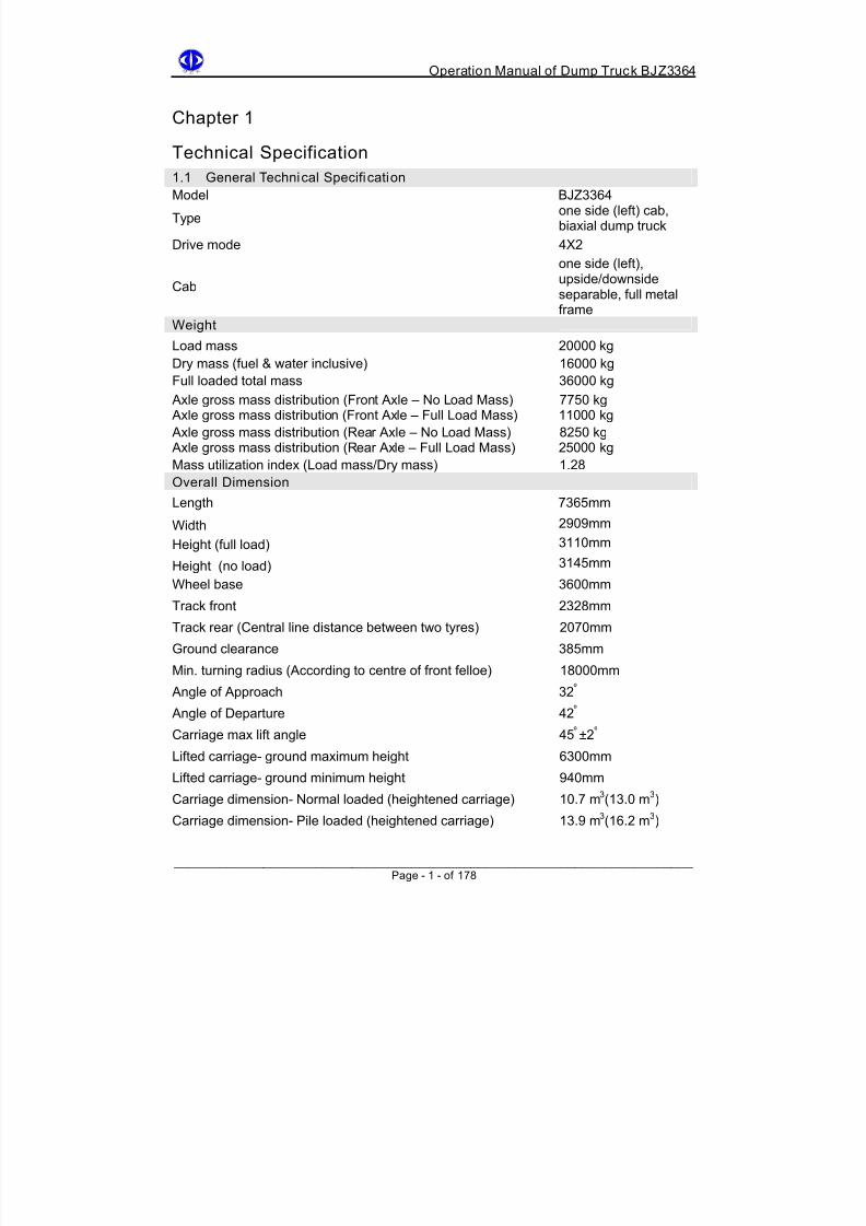
1.1 General Technical Specification
Model BJZ3364
Type one side (left) cab,biaxial dump truck
Drive mode 4X2
Cab
one side (left),upside/downsideseparable, full metalframe
WeightLoad mass 20000 kg
Dry mass (fuel & water inclusive) 16000 kg
Full loaded total mass 36000 kg
Axle gross mass distribution (Front Axle – No Load Mass) 7750 kg
Axle gross mass distribution (Front Axle – Full Load Mass) 11000 kg
Axle gross mass distribution (Rear Axle – No Load Mass) 8250 kg
Axle gross mass distribution (Rear Axle – Full Load Mass) 25000 kg
Mass utilization index (Load mass/Dry mass) 1.28
Overall Dimension
Length 7365mm
Width 2909mm
Height (full load) 3110mm
Height (no load) 3145mm
Wheel base 3600mm
Track front 2328mm
Track rear (Central line distance between two tyres) 2070mm
Ground clearance 385mm
Min. turning radius (According to centre of front felloe) 18000mm
Angle of Approach 32 º
Angle of Departure 42 º
Carriage max lift angle 45 º ±2 º
Lifted carriage- ground maximum height 6300mm
Lifted carriage- ground minimum height 940mm
Carriage dimension- Normal loaded (heightened carriage) 10.7 m3(13.0 m
3)
Carriage dimension- Pile loaded (heightened carriage) 13.9 m
3
(16.2 m
3
)
______________________________________________________________________ Page - 1 - of 178

8/18/2019 d20 Bjz3364 Op Manual
http://slidepdf.com/reader/full/d20-bjz3364-op-manual 12/188
Operation Manual of Dump Truck BJZ3364
Engine
Model CumminsNT-855-C250
Type 6 cylinders in-linewater-cooled 4-stokediesel engine
Aspiration Exhaust turbo
Number of Cylinder – radius × travel distance 6-140mmx152mm
Total emission 14L
Condensation ratio 15:1Max output power/rotate speed 186kw (250hp) / 2100
turns/min
Max torque/rotate speed 1019Nm(104kgForce·meter) /1500 turns/min
Rating rotate speed/max no load rotate speed 2100turns/min/2400turns/min
Idling speed 625turns/minCrank turning direction (facing side of flywheel) anti-clockwiseIgnition order (clockwise) 1-5-3-6-2-4Total mass (with standard accessory) 1258kgDimension (length x width x height) 1570mm x 925mm x
1246mmLubrication Device – Engine
Type Pressure-feedlubrication
Lube oil pressure (2100tunrs/min)241-345kpa
Idling lube oil pressure No less than 102kpa
Lube oil pump Gear pump
Lube oil filter Side stream oil filter Lube oil model CD-15W/40
Cooling Device - Engine
Type Closed circulatingwater-cooler withexpansion chamber
and water softeningplant
Circulation water pump Centrifugal Fuel System Fuel injection pump PT(G)-AFS fuel pump
Type 8 holes
Nozzle pressure 96700kpa
Nozzle hole diameter 0.178mm
Feed pump Gear pump
Fuel filter Primary & SecondarySpeed controller Two plate mechanical
control
______________________________________________________________________ Page - 2 - of 178
8/18/2019 d20 Bjz3364 Op Manual
http://slidepdf.com/reader/full/d20-bjz3364-op-manual 13/188
Operation Manual of Dump Truck BJZ3364
______________________________________________________________________ Page - 3 - of 178
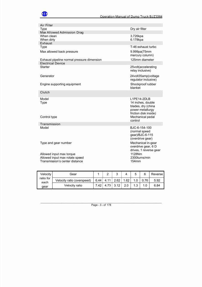
Ai r Fil terType Dry air filter Max Allowed Admission DragWhen clean 3.726kpa
When dirty 6.178kpa
ExhaustType T-46 exhaust turbo
Max allowed back pressure 9.999pa(75mmmercury column)
Exhaust pipeline normal pressure dimension 125mm diameter Electrical Device
Starter 25volt(acceleratingrelay inclusive)
Generator 24volt35amp(voltageregulator inclusive)
Engine supporting equipment Shockproof rubberblanket
Clutch
Model L1PE14-2DLB
Type 14 inches, doubleblades, dry (chinapower metallurgyfriction disk inside)
Control type Mechanical pedalcontrol
TransmissionModel BJC-6-154-100
(normal speedgear)/BJC-6-115(overdrive gear)
Type and gear number Mechanical in-gearoverdrive gear, 6 Ddrives, 1 reverse gear
Allowed input max torque 1128Nm Allowed input max rotate speed 2300turns/min
Transmission’s center distance 154mm
Gear 1 2 3 4 5 6 Reverse
Velocity ratio (overspeed) 6.44 4.11 2.62 1.62 1.0 0.76 5.92
Velocity
ratio for
each
gear Velocity ratio 7.42 4.73 3.12 2.0 1.3 1.0 6.84
8/18/2019 d20 Bjz3364 Op Manual
http://slidepdf.com/reader/full/d20-bjz3364-op-manual 14/188
Operation Manual of Dump Truck BJZ3364
______________________________________________________________________ Page - 4 - of 178
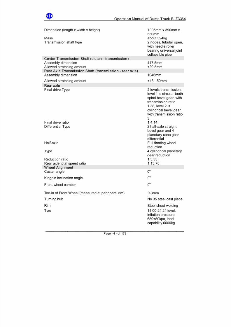
Dimension (length x width x height) 1005mm x 390mm x550mm
Mass about 324kg
Transmission shaft type 2 nodes, tubular open,with needle rollerbearing universal jointcollapsible pipe
Center Transmission Shaft (clutch - transmission) Assembly dimension 447.5mm
Allowed stretching amount ±20.5mm
Rear Axle Transmission Shaft (transmission - rear axle) Assembly dimension 1046mm
Allowed stretching amount +43, -50mm
Rear axleFinal drive Type 2 levels transmission,
level 1 is circular-toothspiral bevel gear, withtransmission ratio1.38, level 2 iscylindrical bevel gearwith transmission ratio3
Final drive ratio 1:4.14
Differential Type 2 half-axle straight
bevel gear and 4planetary cone geardifferential
Half-axle Full floating wheelreduction
Type 4 cylindrical planetarygear reduction
Reduction ratio 1:3.33
Rear axle total speed ratio 1:13.78
Wheel AlignmentCaster angle 0
o
Kingpin inclination angle 9 o
Front wheel camber 0 o
Toe-in of Front Wheel (measured at peripheral rim) 0-3mm
Turning hub No 35 steel cast piece
Rim Steel sheet welding
Tyre 14.00-24.24 level,inflation pressure
650±50kpa, loadcapability 6000kg

8/18/2019 d20 Bjz3364 Op Manual
http://slidepdf.com/reader/full/d20-bjz3364-op-manual 15/188
Operation Manual of Dump Truck BJZ3364
______________________________________________________________________ Page - 5 - of 178
Suspension SystemFront suspension Bi-directional
cylindrical fluid shock
absorber, double slidesymmetricalhalf-elliptic leaf mainspring and two pointsymmetrical rubberauxiliary spring,transmission rod
Rear suspension Double slidesymmetricalhalf-elliptic leaf mainspring and two point
symmetrical rubberauxiliary spring,transmission rod
Steering And BrakeRedirector type GX110C crossover
circulation
Assist type Integral booster withbooster cylinder
Transmission ratio when redirector travels straight 23.27
Foot brake Double pipeline brakeshoe chamber
Hand brake Double gas deflationspring effect brakeshow chamber
Working pressure 750kpa
CarriageCarriage Bucket type, high
strength steel welding,possessing exhaustheat up device
Dumping deviceLifting cylinders One-way 3 stages
extensible hydraulicpressure cylinder, twoside symmetric layout,placed upside downon the external vehicleframe
Fuel pump Double and parallelconnected gear pump,reduction ratio 2.15
Nominal flow rate (1000turns/min hour)
215L/min Rating working pressure 8336kpa
8/18/2019 d20 Bjz3364 Op Manual
http://slidepdf.com/reader/full/d20-bjz3364-op-manual 16/188
Operation Manual of Dump Truck BJZ3364
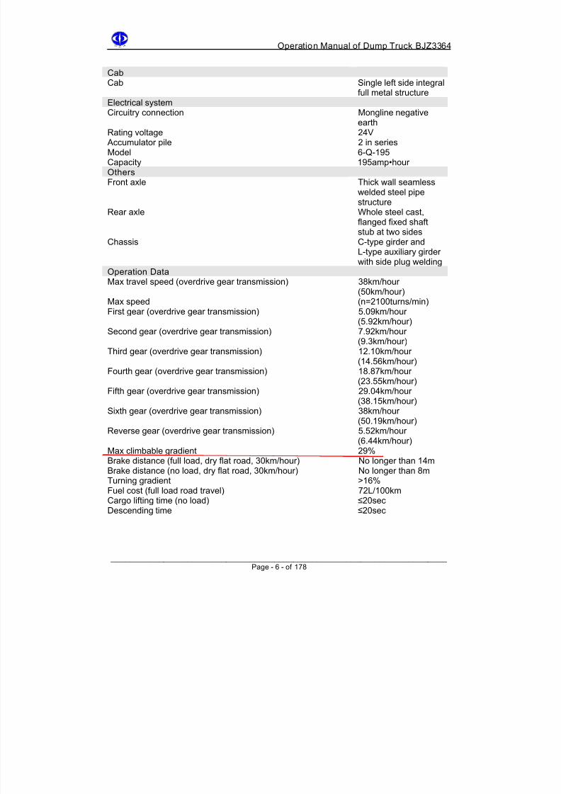
______________________________________________________________________ Page - 6 - of 178
CabCab Single left side integral
full metal structure
Electrical systemCircuitry connection Mongline negativeearth
Rating voltage 24V
Accumulator pile 2 in series
Model 6-Q-195
Capacity 195amp•hour OthersFront axle Thick wall seamless
welded steel pipestructure
Rear axle Whole steel cast,flanged fixed shaftstub at two sides
Chassis C-type girder andL-type auxiliary girderwith side plug welding
Operation DataMax travel speed (overdrive gear transmission) 38km/hour
(50km/hour)Max speed (n=2100turns/min)First gear (overdrive gear transmission) 5.09km/hour
(5.92km/hour)Second gear (overdrive gear transmission) 7.92km/hour
(9.3km/hour)Third gear (overdrive gear transmission) 12.10km/hour
(14.56km/hour)Fourth gear (overdrive gear transmission) 18.87km/hour
(23.55km/hour)Fifth gear (overdrive gear transmission) 29.04km/hour
(38.15km/hour)Sixth gear (overdrive gear transmission) 38km/hour
(50.19km/hour)
Reverse gear (overdrive gear transmission) 5.52km/hour(6.44km/hour)
Max climbable gradient 29%
Brake distance (full load, dry flat road, 30km/hour) No longer than 14m
Brake distance (no load, dry flat road, 30km/hour) No longer than 8m
Turning gradient >16%
Fuel cost (full load road travel) 72L/100km
Cargo lifting time (no load) ≤20sec
Descending time ≤20sec
8/18/2019 d20 Bjz3364 Op Manual
http://slidepdf.com/reader/full/d20-bjz3364-op-manual 17/188
Operation Manual of Dump Truck BJZ3364
______________________________________________________________________ Page - 7 - of 178
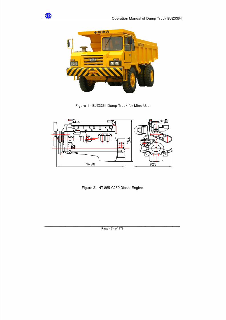
Figure 1 - BJZ3364 Dump Truck for Mine Use
Figure 2 - NT-855-C250 Diesel Engine

8/18/2019 d20 Bjz3364 Op Manual
http://slidepdf.com/reader/full/d20-bjz3364-op-manual 18/188
Operation Manual of Dump Truck BJZ3364
______________________________________________________________________ Page - 8 - of 178
F i g u r e 3 - B J Z 3 3 6
4 D u m p T r u c k D i m e n s i o n

8/18/2019 d20 Bjz3364 Op Manual
http://slidepdf.com/reader/full/d20-bjz3364-op-manual 19/188
Operation Manual of Dump Truck BJZ3364
______________________________________________________________________ Page - 9 - of 178
Figure 4 - BJ374 Dump Truck Traveling Performance

8/18/2019 d20 Bjz3364 Op Manual
http://slidepdf.com/reader/full/d20-bjz3364-op-manual 20/188
Operation Manual of Dump Truck BJZ3364
______________________________________________________________________ Page - 10 - of 178
Chapter 2
Normal Use and Maintenance
2.1 CONTROL SYSTEM AND NAVIGATIONAL PANEL
2.1.1 Control System Location (See Figure 5)
Figure 5 - Control System Sketch Map
1 Transmission gear lever 2 Accelerator pedal 3 Brake pedal 4 Clutch pedal
5 Steering wheel 6 Instrument console 7 Combinational switch
Gearlever is at right side of the driver seat. Step on “two feet clutch” to switch gear. Using
first gear to start when with heavy load, second gear with no load, when speed up or speed
down, do not switch gear with more than one level. Gearlevers of transmission case with
overdrive gear and with normal gear have different position at fifth gear and sixth gear. See
Figure 6 and 7.

8/18/2019 d20 Bjz3364 Op Manual
http://slidepdf.com/reader/full/d20-bjz3364-op-manual 21/188

8/18/2019 d20 Bjz3364 Op Manual
http://slidepdf.com/reader/full/d20-bjz3364-op-manual 22/188

8/18/2019 d20 Bjz3364 Op Manual
http://slidepdf.com/reader/full/d20-bjz3364-op-manual 23/188
Operation Manual of Dump Truck BJZ3364
______________________________________________________________________ Page - 13 - of 178
2.1.2 Cab Instrument Panel
Figure 10 - Instrument panel Sketch Map
01 Ampere meter 13 Handbrake switch
02 Two-pointer barometer 14 Dipped headlight switch
03 Fuel meter 15 Front foglight switch
04 Oil pressure meter 16 Width indicator switch
05 Speedometer 17 Lift valve
06 Signal indicator 18 Ignition switch
07 Tachometer 19 Engine hour meter
08 Hazard light switch 20 Fuse case
09 Fan switch 21 Water temperature gauge
10 Lift switch 22 Engine Cutoff switch11 Headlight switch 23 Start button
12 Working light switch 24 Socket for external light

8/18/2019 d20 Bjz3364 Op Manual
http://slidepdf.com/reader/full/d20-bjz3364-op-manual 24/188
Operation Manual of Dump Truck BJZ3364
______________________________________________________________________ Page - 14 - of 178
2.1.3 Signal Indicator Explanation
1. Turning left indicator: on when combinational switch is turned to left
2. High beam: on when using combination switch to change front headlight to far light
3. High water temperature warning indicator: on when engine water temperature is
above 120
4. Low pressure indicator: on when failure in arrester or pressure lower than 450kpa
5. Low oil pressure indicator: on when engine oil pressure is too low
6. Parking brake indicator: on when using hand brake for parking7. Travel switch indicator: on when carriage is lifted and travel switch is on
8. Turning right indicator: on when combinational switch is turned to right
2.1.4 Switch Usage
As shown above, two 6-join seesaw switches have blank covers at first two positions.
Driver can use seesaw switches when in need. Meanwhile the indicator will be on.
This is followed by hazard light switch, fan switch, lift switch, head light switch, width
indicator switch, front foglight switch, dipped headlight switch and working light switch.
Combinational switches are used for turning left/right indicator, far/near light switching,
horn and wiper.

8/18/2019 d20 Bjz3364 Op Manual
http://slidepdf.com/reader/full/d20-bjz3364-op-manual 25/188
Operation Manual of Dump Truck BJZ3364
______________________________________________________________________ Page - 15 - of 178
Ignition switch - insert key into the switch and turn it (clockwise) to level 1 to electrify all
devices, turn to level 2 and push the start button to electrify the engine, both levels are
immediate switch and release the turning when ignited. If starting fails, try again in 2
minutes.
To cut off engine, push the extinguishing button, the engine will be extinguished.
2.1.5 Instrument Panel Indicators
1. Barometer: Indicate air reservoir pressure.
2. Ampere Meter: Indicate direction - positive or negative depend on if it is an input
accumulator or output accumulator.
3. Speedometer: indicate traveling speed and cumulated travel mileage.
4. Tachometer, hour meter: indicate engine speed and accumulated working hour.
5. Fuel meter: indicate fuel level in the fuel tank.
6. Water thermometer: point between 75 ºC -90ºC under normal condition.
7. Fuel barometer: Indicate engine fuel pressure. When it is below standard value,
warning switch is closed, low pressure indicator is on. Parking inspection is required.
2.1.6 Use Of Control Handle and Socket For Working Light
1. When lifting carriage, firstly connect the electromagnetic valve then lower the lifting
handle. After carriage reaches certain height, the lifting indicator is on.
2. When using hand brake for idling parking, the corresponding indicators should turn
on.
3. Socket for external light can be used for subsidiary maintenance light.
Although accumulator capacity suffices the use of each electrical device, for longer lifespan
of the battery and wiring harness, and reducing the cost, try to avoid simultaneous working
of the electrical devices.
If any device is not working, firstly check if the fuse is broken. If the device is still not
working after replacement of the fuse, refer to the device theory map to solve the problem.

8/18/2019 d20 Bjz3364 Op Manual
http://slidepdf.com/reader/full/d20-bjz3364-op-manual 26/188
Operation Manual of Dump Truck BJZ3364
______________________________________________________________________ Page - 16 - of 178
2.2 NEW VEHICLE CHECK-UP
Simple road tests have been done fore the vehicle leaves the factory. In order to avoid
accidents during transportation, necessary check-ups should be done before use.
Check-up contents are as followings:
1. Check and fasten each bolt, nut and lockpin.
2. Check engine, transmission case, rear axle, dynamic turning system, lifting
system fuel level, capacity and fuel quality, refuel or replace if necessary.
Check the above assembly pipeline connection.
3. Check if the tyre pressure is within the specification, which is front and rear tyre
pressure 650 ±50kpa
4. Check accumulator fluid level, it should be 6-10mm higher than the clapboard.
5. Check electrolyte proportion, it should be 1.29 when the temperature is 15ºC.
For each 10ºC increase/decrease, the proportion will increase/decrease by 0.007
respectively. Add or adjust fluid if necessary. Check if the connection between
lead and electric bottle is tightened, and if the electricity circuitry is working.
6. Check engine, starting device, voltage adjustor etc.
7. Check elasticity of fans or generator’s belt. When slightly depressed, the belt should
sink about 10mm.
8. Check for each connectors of engine cooling system. Check if fuel supply system is
working when the engine starts.
9. Check brake efficiency, i.e. brake distance, to see if there is any deflection or
stagnancy. Also check any leakage in the pipelines. If there are any faults,
troubleshoot the cause and solve them immediately.
10. After the vehicle starts, check if the turning system is working and if the drive panel
and signals are working.
8/18/2019 d20 Bjz3364 Op Manual
http://slidepdf.com/reader/full/d20-bjz3364-op-manual 27/188
Operation Manual of Dump Truck BJZ3364
______________________________________________________________________ Page - 17 - of 178
2.3 NEW VEHICLE RUN IN AND MAINTENANCE
2.3.1 Significance Of New Vehicle Run
New vehicle’s lifespan, extension of interval of heavy repair and working reliability and
economically depends largely on this new vehicle run at the beginning and the
maintenance quality.
Although new vehicles or vehicles which just completed their heavy repair have done
vehicle run before leaving the factory, the surface of accessories is still rough. The shape of
accessories after machining, coordination and clearance between each part still have
some deviation. When the vehicle is operating, due to the friction the temperature will rise.
Because the clearance between each part is small, the lubricants cannot easily reach those
parts, hence resulting in bad lubrication and worsening the wear and tear.
Therefore, new vehicle run in is necessary, otherwise over friction can occur in the parts if
new vehicles are immediately put into full load travel after leaving the factory. The thermal
expansion will result in biting of the parts and abnormal wear and tear. Vehicle’s lifespan
will be largely reduced. Hence it is important to carry out the new vehicle run in to maintain
a normal working condition to prolong the lifespan.
New vehicles or those which have just completed the heavy repair have the running
regulation. For mine use vehicle, BJZ3364 Dump Truck, the continuous travel time is 150
hours in the run. There are specific regulation for the use and maintenance of the vehicle
during the run.
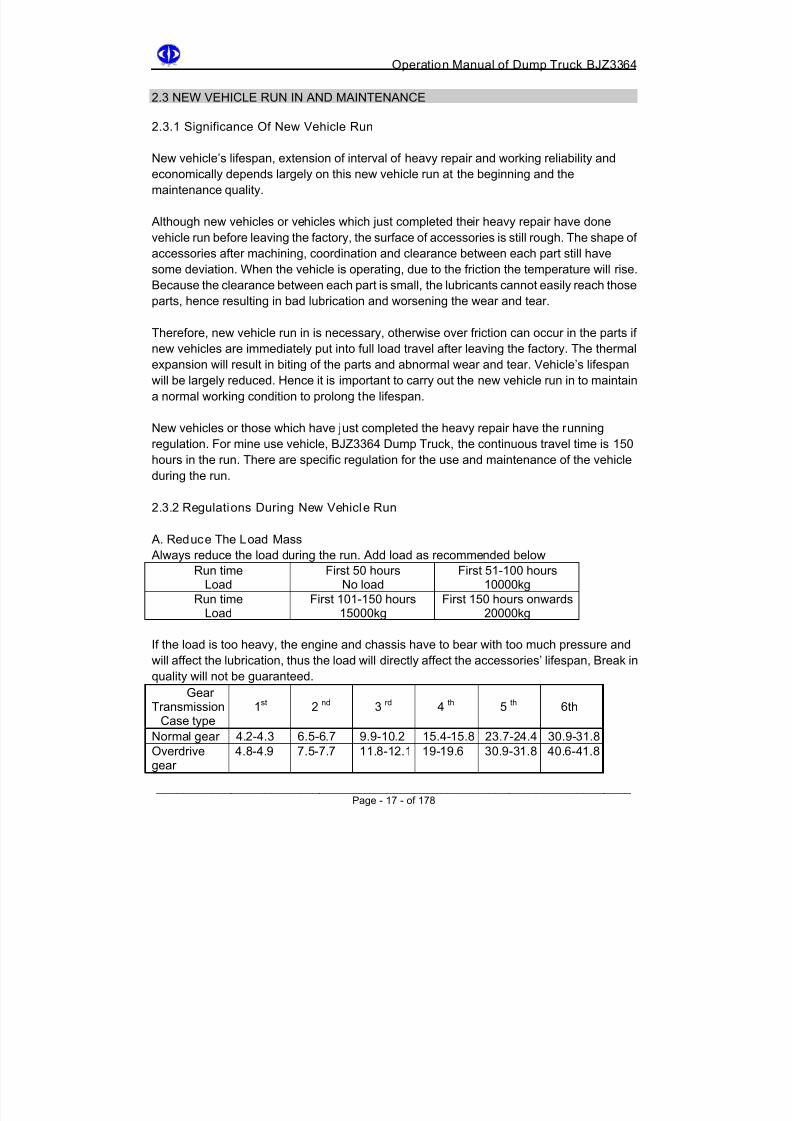
2.3.2 Regulations During New Vehicle Run
A. Reduce The Load Mass
Always reduce the load during the run. Add load as recommended below
Run timeLoad
First 50 hoursNo load
First 51-100 hours10000kg
Run timeLoad First 101-150 hours15000kg First 150 hours onwards20000kg
If the load is too heavy, the engine and chassis have to bear with too much pressure and
will affect the lubrication, thus the load will directly affect the accessories’ lifespan, Break in
quality will not be guaranteed.
GearTransmission
Case type1st 2 nd 3 rd 4 th 5 th 6th
Normal gear 4.2-4.3 6.5-6.7 9.9-10.2 15.4-15.8 23.7-24.4 30.9-31.8
Overdrivegear 4.8-4.9 7.5-7.7 11.8-12.1 19-19.6 30.9-31.8 40.6-41.8
8/18/2019 d20 Bjz3364 Op Manual
http://slidepdf.com/reader/full/d20-bjz3364-op-manual 28/188
Operation Manual of Dump Truck BJZ3364
______________________________________________________________________ Page - 18 - of 178
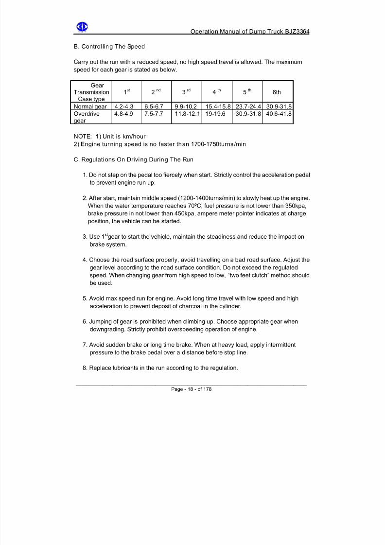
B. Control ling The Speed
Carry out the run with a reduced speed, no high speed travel is allowed. The maximum
speed for each gear is stated as below.
GearTransmission
Case type1st 2 nd 3 rd 4 th 5 th 6th
Normal gear 4.2-4.3 6.5-6.7 9.9-10.2 15.4-15.8 23.7-24.4 30.9-31.8
Overdrivegear
4.8-4.9 7.5-7.7 11.8-12.1 19-19.6 30.9-31.8 40.6-41.8
NOTE: 1) Unit is km/hour
2) Engine turning speed is no faster than 1700-1750turns/min
C. Regulations On Driving During The Run
1. Do not step on the pedal too fiercely when start. Strictly control the acceleration pedal
to prevent engine run up.
2. After start, maintain middle speed (1200-1400turns/min) to slowly heat up the engine.
When the water temperature reaches 70ºC, fuel pressure is not lower than 350kpa,
brake pressure in not lower than 450kpa, ampere meter pointer indicates at charge
position, the vehicle can be started.
3. Use 1st gear to start the vehicle, maintain the steadiness and reduce the impact on
brake system.
4. Choose the road surface properly, avoid travelling on a bad road surface. Adjust the
gear level according to the road surface condition. Do not exceed the regulated
speed. When changing gear from high speed to low, “two feet clutch” method should
be used.
5. Avoid max speed run for engine. Avoid long time travel with low speed and high
acceleration to prevent deposit of charcoal in the cylinder.
6. Jumping of gear is prohibited when climbing up. Choose appropriate gear when
downgrading. Strictly prohibit overspeeding operation of engine.
7. Avoid sudden brake or long time brake. When at heavy load, apply intermittent
pressure to the brake pedal over a distance before stop line.
8. Replace lubricants in the run according to the regulation.

8/18/2019 d20 Bjz3364 Op Manual
http://slidepdf.com/reader/full/d20-bjz3364-op-manual 29/188

8/18/2019 d20 Bjz3364 Op Manual
http://slidepdf.com/reader/full/d20-bjz3364-op-manual 30/188
Operation Manual of Dump Truck BJZ3364
______________________________________________________________________ Page - 20 - of 178
C. After The Run
A maintenance is necessary when the run is finished. Check and verify the connection
points of the parts, fasten and adjust them if necessary. After the run the vehicle can
therefore start its normal operation.
Main contents for maintenance after the run:
1. Clean all the paths for lubricants and all the filters including: air filter, engine first
and secondary filter, filter for fuel tank, filter for turning oilcan and filter for lifting
fluid pressure fuel.
2. Replace all the lubricants and engine machine oil, secondary filter and filter core
for air filter.
3. Measure the pressure of engine air cylinder. The pressure of each cylinder shouldbe no less than 3550kpa when 600 turns/min. The pressure difference of each
cylinder should be no larger than 175kpa.
4. Following the rule “center first, then around”, fasten the bolts of air cylinder shell
2-3 times. Screw down moment is 235-251Nm.
For normal diesel engine’s iron cast cylinder shell, first warm-up, then check the
tightness of air cylinder shell’s bolts to prevent bad sealing condition of cylinder
shell due to thermal expansion of the bolts. This bad sealing condition will lead to
damage of liner of air cylinder shell.
5. Fasten the exposed related bolts (refer to “maintenance in the run”), eliminate their
looseness and undesired clearance.
6. Check efficiency of brake system, adjust brake drum clearance to 0.3-0.5mm,
eliminate gas leak of brake pipelines.
7. Check and adjust clutch pedal free play.
8. Check and adjust the technical condition of front axle assembly’s turning device
9. Check and adjust front tyre toe (5-7)mm.
10. Check and adjust the steering drag link and steering tie rod, eliminate any possible
clearance in between.
11. Fasten related bolts and nuts of the turning system.
12. Check and adjust fans, elasticity of engine belt.13. Check the fastness of tie-ins in the accumulator and electric circuits.
8/18/2019 d20 Bjz3364 Op Manual
http://slidepdf.com/reader/full/d20-bjz3364-op-manual 31/188
Operation Manual of Dump Truck BJZ3364
______________________________________________________________________ Page - 21 - of 178
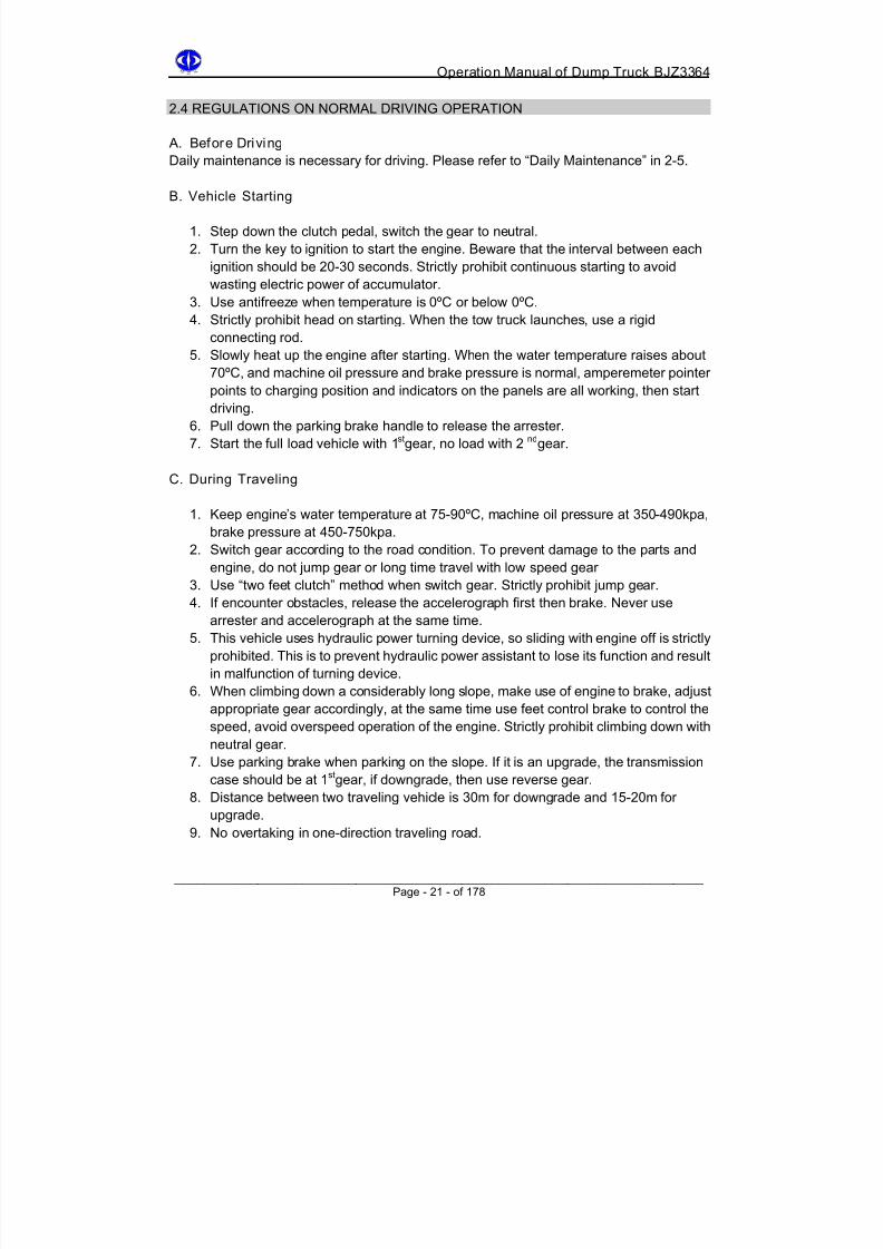
2.4 REGULATIONS ON NORMAL DRIVING OPERATION
A. Before Driving
Daily maintenance is necessary for driving. Please refer to “Daily Maintenance” in 2-5.
B. Vehicle Starting
1. Step down the clutch pedal, switch the gear to neutral.
2. Turn the key to ignition to start the engine. Beware that the interval between each
ignition should be 20-30 seconds. Strictly prohibit continuous starting to avoid
wasting electric power of accumulator.
3. Use antifreeze when temperature is 0ºC or below 0ºC.
4. Strictly prohibit head on starting. When the tow truck launches, use a rigid
connecting rod.5. Slowly heat up the engine after starting. When the water temperature raises about
70ºC, and machine oil pressure and brake pressure is normal, amperemeter pointer
points to charging position and indicators on the panels are all working, then start
driving.
6. Pull down the parking brake handle to release the arrester.
7. Start the full load vehicle with 1st gear, no load with 2 nd gear.
C. During Traveling
1. Keep engine’s water temperature at 75-90ºC, machine oil pressure at 350-490kpa,
brake pressure at 450-750kpa.
2. Switch gear according to the road condition. To prevent damage to the parts and
engine, do not jump gear or long time travel with low speed gear
3. Use “two feet clutch” method when switch gear. Strictly prohibit jump gear.
4. If encounter obstacles, release the accelerograph first then brake. Never use
arrester and accelerograph at the same time.
5. This vehicle uses hydraulic power turning device, so sliding with engine off is strictly
prohibited. This is to prevent hydraulic power assistant to lose its function and result
in malfunction of turning device.6. When climbing down a considerably long slope, make use of engine to brake, adjust
appropriate gear accordingly, at the same time use feet control brake to control the
speed, avoid overspeed operation of the engine. Strictly prohibit climbing down with
neutral gear.
7. Use parking brake when parking on the slope. If it is an upgrade, the transmission
case should be at 1st gear, if downgrade, then use reverse gear.
8. Distance between two traveling vehicle is 30m for downgrade and 15-20m for
upgrade.
9. No overtaking in one-direction traveling road.

8/18/2019 d20 Bjz3364 Op Manual
http://slidepdf.com/reader/full/d20-bjz3364-op-manual 32/188
Operation Manual of Dump Truck BJZ3364
______________________________________________________________________ Page - 22 - of 178
D. Parking
1. Release the accelerator, step on the clutch pedal to switch the gearlever to neutral,
slowly step the brake pedal till the vehicle stops.
2. After the vehicle stops, push up the parking brake handle. If the parking brake
functions, the relative indicator will be on in the panel.
3. When parking, if the parking time is short (5-8min), engine may not be off, to prevent
wastage of electricity when start again. If parking time is long, then switch off the
engine, otherwise long idling time will lead to incomplete combustion to produce
accumulating charcoal and diluted lubricants.
4. Unless in the situation of flying car, must not use “emergency choke” to switch off the
engine.
5. Before off the engine, the engine should be idling running for 3-5min to let lubricants
and cooling fluid to cool down firebox bearing and shaft and thus cool down the
engine. This is especially important for worm wheel pressure engine.6. Pull up the off engine switch, close the starting switch, pull out the key and switch off
the power circuit.
7. In winter, often replace the cooling fluid in the engine.
8. When parking for a long time, the vehicle should be placed in a horizontal parking
place, with support of stow-wood to lift up the vehicle from ground.
E. Lifting of carriage
1. Accurately switch the gearlever to neutral.
2. Step the clutch pedal till the end, switch on the lifting function, put the lifting control
handle to “lift” position, and then slowly release the clutch.
3. Step on the gas to accelerate the engine, gradually lift the carriage and dump the
load.
4. During the dumping put the lifting control handle to “dump” position to let the
carriage automatically get back to its original position.
5. When the carriage if fully lowered down, step the clutch pedal, switch off the lifting
function to disconnect the power output.
6. No moving of the vehicle if the carriage is not completely lowered down.
F. Regulations on use in winter
1. In winter, use special fuel and lubricants (for winter use) for engine and chassis
assembly. Details please refer to 03 “Lubrication”.
2. Daily release the fuel tank’s sewerage.
3. When retrieving the vehicle, open all the water releasing taps of the engine to
release all the cooling fluid.
4. Use a warm cylinder to start in winter. Warm-up the engine to 50 ºC (fill in hot water
into the cooling system), idling running should be no less than 5min, do not fill in
cooling fluid after start to prevent cracking in the cylinder.
8/18/2019 d20 Bjz3364 Op Manual
http://slidepdf.com/reader/full/d20-bjz3364-op-manual 33/188
Operation Manual of Dump Truck BJZ3364
______________________________________________________________________ Page - 23 - of 178
5. Gradually heat up the engine till 75 ºC, then start the vehicle.
6. When parking outdoor with temperature -30 ºC and below, disassemble the storage
battery and put it in a warm place.
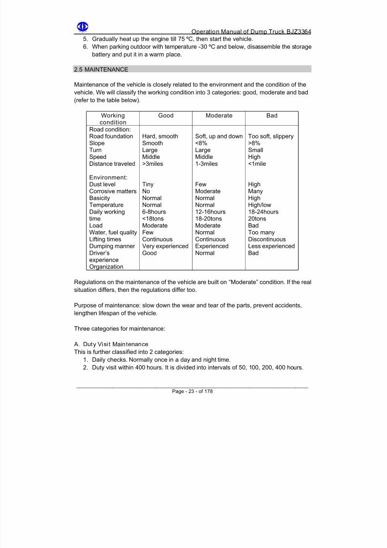
2.5 MAINTENANCE
Maintenance of the vehicle is closely related to the environment and the condition of the
vehicle. We will classify the working condition into 3 categories: good, moderate and bad
(refer to the table below).
Workingcondition
Good Moderate Bad
Road condition:Road foundationSlopeTurnSpeedDistance traveled
Environment:Dust levelCorrosive mattersBasicityTemperatureDaily working
timeLoadWater, fuel qualityLifting timesDumping mannerDriver’sexperienceOrganization
Hard, smoothSmoothLargeMiddle>3miles
TinyNoNormalNormal6-8hours
<18tonsModerateFewContinuousVery experiencedGood
Soft, up and down<8%LargeMiddle1-3miles
FewModerateNormalNormal12-16hours
18-20tonsModerateNormalContinuousExperiencedNormal
Too soft, slippery>8%SmallHigh<1mile
HighManyHighHigh/low18-24hours
20tonsBadToo manyDiscontinuousLess experiencedBad
Regulations on the maintenance of the vehicle are built on “Moderate” condition. If the real
situation differs, then the regulations differ too.
Purpose of maintenance: slow down the wear and tear of the parts, prevent accidents,
lengthen lifespan of the vehicle.
Three categories for maintenance:
A. Duty Visi t Maintenance
This is further classified into 2 categories:
1. Daily checks. Normally once in a day and night time.
2. Duty visit within 400 hours. It is divided into intervals of 50, 100, 200, 400 hours.

8/18/2019 d20 Bjz3364 Op Manual
http://slidepdf.com/reader/full/d20-bjz3364-op-manual 34/188
Operation Manual of Dump Truck BJZ3364
______________________________________________________________________ Page - 24 - of 178
B. Preventive Maintenance
Preventive maintenance is also called forced maintenance. It is done from 800 to 6000
hours. It is divided into intervals of 800, 1500, 3000, 4500, 6000 hours. After 8000 hours the
vehicle needs to send for heavy repair.
C. Emergency Maintenance
Maintenance for emergency cases.
2.5.1 Daily Checks
Contents:
1. Clean the insides of vehicle and chassis, check if there is any loss of the parts.2. Check the working conditions of lights, panel, water scrape device, horn, working
and parking brake, turning system and other control systems
3. Check the fuel level of engine fuel and chassis machine oil. The fuel level should not
be lower than the middle position of two dipstick scale.
4. Discharge the fuel tank ponding daily. Check the smoothness of the venthole.
5. Check fuel capacity. Add fuel at every shift. Keep sufficient fuel in the tank for better
cooling of the pump nozzle.
6. Check water level of the cooling fluid. It should be lower than expansion case shell
by 30-50mm. Avoid using alkaline liquid.
7. Check the indicator of air filter, when it shows red signal, clean or replace filter core.
2.5.2 Maintenance Within 50 Hours
A. Apply Lubricants Once Every 50 Hours.
Refer to “Lubrication” (table 3) for the parts to be lubricated.
B. Parts That Need To Be Maintained After Every 50 Hours Travel.
1. Check and clean air filter. Use 680kpa compressed air to blow it.
2. Check if there is any deposit in the reservoir tank, for example, water andfeculence.
3. Check the electrolyte level of the storage battery, it should be 6-10mm higher
than the block board.
C. Parts That Need To Be Maintained After Every 100 Hours Travel
1. Check the fuel level of power turning system’s fuel tank. Refill if insufficient.
2. Check the fuel level of transmission case. Refill if insufficient,
3. Check rear axle’s main reducer shell and fuel level of rear tyre planetary reducer.
Refill if insufficient.

8/18/2019 d20 Bjz3364 Op Manual
http://slidepdf.com/reader/full/d20-bjz3364-op-manual 35/188
Operation Manual of Dump Truck BJZ3364
______________________________________________________________________ Page - 25 - of 178
4.Check front and rear tyre pressure. It should be 650±50kpa.
5.Check if there is any damage on front and rear tyre and hub.
D. Parts That Need To Be Maintained After Every 200 Hours Travel
1.Replace the filter core of engine machine oil filter.
2.Replace engine machine oil.
3.Clean fuel filter.
4.Fasten nuts of hub fixed on the tyre.
5.Check and fasten the U type bolts and nuts of front and rear suspension shell.
E. Parts That Need To Be Maintained After Every 400 Hours Travel
1. Replace external filter core of air filter.
2. Replace filter core of fuel filter.
3. Replace the hydraulic fuel of power turning system and filter core of filter.
4. Fasten flange bolts of front and rear transmission shaft.5. Check and adjust the toe to be 5-7mm.
6. Check and fasten bolts of front and rear suspension shelf.
7. Check the clearance between exhaust valve and rocker. Carry out the check-up
according to the instructions in the engine manual.
8. Fasten the bolts of main reducer shell and rear axle shell.
9. Fasten the nuts of steering drag link and steering tie rod.
10. Check and eliminate any possible clearance between steering drag link and
steering tie rod.
11. Lubricates the hub of front and rear tyre.
2.5.3 Preventive Maintenance
A.Parts That Need To Be Maintained After Every 800 Hours Travel
1. Clean the furring in engine radiator.
2. Lubricate the bearing and lining of engine starter.
3. Replace the inner filter core of air filter.
4. Use gasoline to clean the fuel filter of lifting system
5. Replace the lubricants of rear axle’s main reducer and rear tyre’s planetary
reducer.6. Replace the lubricants of transmission case.
7. Check and fasten the bolts and nuts of redirector.
8. Adjust the clutch.
9. Check and adjust the clearance between steering stub seat and front axle head.
10. Adjust the arrester.
11. Completely check the wiring.

8/18/2019 d20 Bjz3364 Op Manual
http://slidepdf.com/reader/full/d20-bjz3364-op-manual 36/188
Operation Manual of Dump Truck BJZ3364
______________________________________________________________________ Page - 26 - of 178
B.Parts that need to be maintained after every 1500 hours travel.
1. Adjust pump nozzle and valve.
2. Clean the fuel tank and check the fuel supplier pipeline.
3. Fasten engine’s kickstand, air entering and exhausting pipelines, accelerograph
lever and bolts of emergency engine off device.
4. Check the clearance between transmission shaft spline and cover, fasten the
flange bolts.
5. Check transmission case’s suspension shelf, fasten the bolts and adjust the gear
switching system.
6. Check the position of front rear, steering drag link and steering tie rod.
7. Check front tyre’s positioning device, adjust the hydraulic positioning valve of
turning device if necessary.
8. Clean steel plate’s spring and apply lead lubricants between the reeds, fasten
the bolts.
C.Parts That Need To Be Maintained Af ter Every 3000 Hours Travel
1. Completely adjust turing steering drag link and steering tie rod.
2. Examine and repair the gas system.
3. Tyre transposition of replacing tyre (refer to Figure 11).
Figure 11 - Tyre Transposit ion
4. Check the air compressor, replace rubber gasket and tube.5. Replace pump nozzle, and just valve.
6. Replace fan and engine’s belts.
7. Clean the cylinder shell, rub the valve.
8. Replace water tank’s tube.
9. Check the max and min turning speed of the engine.
10. Replace clutch friction disk and adjust clutch control system.
11. Replace the rubber supporting of shock absorber.

8/18/2019 d20 Bjz3364 Op Manual
http://slidepdf.com/reader/full/d20-bjz3364-op-manual 37/188
Operation Manual of Dump Truck BJZ3364
______________________________________________________________________ Page - 27 - of 178
D.Parts That Need To Be Maintained After Every 4500 Hours Travel
1. Replace the high pressure tube of the power turning device.
2. Check the lifting fuel cylinder, distribution valve and power take-off, replace high
pressure tube and lifting fuel.
3. Open the transmission case’s cover, check the shift fork, gear wheel and fork
kickstand, replace if there is any damage on the parts.
4. Check and repair shock absorber and replace its oil.
5. Check and repair or replace front steel plate spring lining, front and rear steel
board spring lining or any other lining.
6. Check the sphere surface bearing of rear suspension shelf thrust lever.
7. Replace the gas pipeline tube of gas device.
E.Parts That Need To Be Maintained After Every 6000 Hours Travel1. Check supercharger of diesel engine.
2. Check compressed pressure of each engine cylinder.
3. Check working condition of cooling system thermostat.
4. Check clutch assembly.
5. Check and repair front axle.
6. Check and repair rear axle differential.
7. Check and repair engine and starting motor.
F. Heavy Repair After 8000 Hours Travel
2.5.4 Notices For Maintenance
A. Basic Requirement For Accessories, Parts And Assembly
1. Clean the accessories, parts and assembly when necessary. Clean and rub-up
using compressed air.
2. No scratch, burr or damage on the surface of accessories and parts. Do not
whack machining surface using steel hammer. If need to whack machining
surface, use a wooden, rubber and soft alloy hammer.3. Refit the scratches if the repair does not affect cooperation dimension.
B. Bearing Assembly
1. Bearing should remain intact till assembly. After check-up, dip into gasoline or
coal oil to wash and dry.
2. When pressing bearing, do not let bearing ball or pole transfer external force,
slowly apply force on the outer circle of bearing.
3. Carry out the check and adjustment of bearing only after bearing bolts are
fastened.
8/18/2019 d20 Bjz3364 Op Manual
http://slidepdf.com/reader/full/d20-bjz3364-op-manual 38/188
Operation Manual of Dump Truck BJZ3364
C. Rubber Oil Seal Assembly
1. Oil seal should be clean, no scratch on working blade and surface. Therefore,
check carefully for the working surface before putting the flange mandrel and
seat ring into the oil seal, check if there is any burr, sharp angle, sharp side
(including the assembling tools used) or any other scratch. Apply engine
lubricants on the oil seal pressure surface. At the same time, apply butter on the
working blade and surface. If it is a double blade oil seal, apply 1/2 butter on the
double blade mouth.
2. During pressing, apply force uniformly on oil seal till the end. Avoid askew or
overexert to damage oil seal. Do not use hammer or other tools to directly whack
on oil seal surface.
3. During assembly, beware of oil seal spring (drop or missing). It is better to dip oil
seal into grease for 4-8 minutes before assembly.
4. During spray-painting and gelatinizing, do not wet the oil seal surface.
D. Lining assembly
1. Metal lining for adjusting purpose and gasket surface should be smooth. Use
oiled cloth to clean it before assembly.
2. Dip the paper gasket for sealing into clean engine lubricant or gelatinize and lead
oil before assembly.
E. Screw Thread Connection
1. During assembly, beware of any drop of spring gasket, uncork pin or other
locking or stopping accessories. Replace them if damaged.
2. When using steel wire for lock up, tighten the wire according to the regulations to
guarantee the lock-stop function.
3. At the joint surface of multi bolts, except for special situation, the bolts should be
tightened in decussation (do not screw one bolt to the regulated torque at one
time).
4. Keep the screw thread clean, clean the oil and mud. Avoid massy button of nuts
with large diameter. Use file to repair if there is damage on screw thread.
______________________________________________________________________ Page - 28 - of 178

8/18/2019 d20 Bjz3364 Op Manual
http://slidepdf.com/reader/full/d20-bjz3364-op-manual 39/188
Operation Manual of Dump Truck BJZ3364
Chapter 3
Lubrication
Lubricating the vehicle correctly can greatly reduce the wear and tear of the parts andvehicle’s frictional resistance.
Clean the lubricating parts before lubrication to avoid mixture of lubricants and dirt.
When replace assembly machine oil, wait till the vehicle to stop and the temperature of
assembly is not cooled down yet, so that all the dispose oil and dirt will be discharged.
Clean the lubricating nozzle before applying the lubricants, grease gun should be open up
and clean in the coal oil once in a while.
After lubrication, rub out the spilled lubricants on the parts to avoid deposit of dirt on the
parts.
BJZ3364 Dump Truck uses specified lubricants (refer to table 1). Table 2 provided the
recommended periods for replacement of lubricants and washing for engine and chassis.
In different mine areas, roads or working condition, please refer to this table according to
the local situation and decide the replacement period of the lubricants.
Table 1 - Dump Truck oil specifications, parts, capacity and period for washing and
replacementCapacity (litre)# Parts
BJZ3361
BJZ3363
Specification Interval(hours)
Replacementperiod
BJZ3364
1 Fuel tank 200 200 200 Summer:#0,#10 diesel oilWinter: #-10. #-35 diesel oil
Daily Every 1500hours
2 Enginemachine oil
chassis
17 23.7 23-26
Whole year use 15W/40CD diesel oil Daily Every 200hours
3 Water tank 50 50 52 Drinking water or water withoutbasicityWinter: add antifreeze
Daily Every 800hours
4 Turninghydraulicoil tank
6 6 6 Summer: #46 engineered hydraulicoilWinter: #32 engineered hydraulic oil
Every 100 Every 400hours
5 Transmission
10 10 10 #22 synthesized gear oil Every 100 Every 800hours
6 Rear axlemain
reducer
17 17 17 #22 synthesized gear oil Every 100 Every 800hours
7 Rear tyreplanetaryreducer
14 14 14 #22 synthesized gear oil Every 100 Every 800hours
8 Lifting oiltank
95 95 95 Summer: #46 engineered hydraulicoilWinter: #32 engineered hydraulic oil
Every 4500hours
9 Pole typeshock
absorber
1.2 1.2 1.2 Specified spindle oilStandard: SY1206-74
Every 4500hours
______________________________________________________________________ Page - 29 - of 178

8/18/2019 d20 Bjz3364 Op Manual
http://slidepdf.com/reader/full/d20-bjz3364-op-manual 40/188
Operation Manual of Dump Truck BJZ3364
Table 2 Time table for washing and replacing filter core of filter
Time tablePart of filter Quantity
Every 50
hours
Every 100
hours
Every 200
hours
Every 400
hours
Every 800
hoursDiesel oilfilter core
Primary1Secondary1
WashWash
ReplaceReplace
Enginemachine oilfilter core
Primary1Socondary1
WashWash
ReplaceReplace
Air filter filtercore
Inner1Outer1
Wash Replaceouter filter
core
Replaceinner filter
core
Powerturning filter
core
1 Wash Replace
Lifting oil filterweb 1 Wash
Table 3 Lubricating location and timing
# Location #points
Lubricantspecification
Every50
hours
Every100
hours
Every200
hours
Every400
hours
Every800
hours
Every1500hours
1 Fan beltshaft
1 #3 lithiumSY1412-75
√
2 Accelera-tor pedal
shaft
1 #1 or #2calcium
sodiumSY1403-77
√
3 Cab doorreamshaft
2 Same asabove
√
4 Clutchand
brakepedalshaft
3 Same asabove
√
5 Clutchfork shaft
3 Same asabove
√
6 Clutchmain
detachedshaft
23
#2 lithiumSY1412-75
√
7 Steeringtie rodand
steeringdrag linkreamer
4 #1 or #3calciumsodium
SY1043-77
√
8 Fronttransmission shaft
andgimbal
3 Same asabove
√
______________________________________________________________________ Page - 30 - of 178

8/18/2019 d20 Bjz3364 Op Manual
http://slidepdf.com/reader/full/d20-bjz3364-op-manual 41/188
Operation Manual of Dump Truck BJZ3364
# Location #points
Lubricantspecification
Every50
hours
Every100
hours
Every200
hours
Every400
hours
Every800
hours
Every1500hours
9 Reartransmission shaft
andgimbal
2 Same asabove
√
10 Frontaxle main
pin
4 Same asabove
√
11 Frontboardspring
front pin
2 Same asabove
√
12 Frontboardspring
rear pin
2 Same asabove
√
13 Rearboardspring
rear pin
4 Same asabove
√
14 Pushlever
shaft pin
4 Same asabove
√
15 Frontbrakeshoe
shaft pin
4 Same asabove
√
16 Front
brakelobe pin
2 Same as
above
√
17 Rearbrakeshoe
shaft pin
4 Same asabove
√
18 Rearbrake
lobe pin
2 Same asabove
√
19 Liftingcylinderup downbearing
4 Same asabove
√
20 Carriageshaft
bearing
2 Same asabove
√
21 Front tyrehub
bearing
2 #2 lithiumSY1412-75
√
22 Reartyre hubbearing
2 #1 or #3calciumsodium
SY1403-77
√
23 Enginebearing
1 #10 machineoil
GB443-64
√
______________________________________________________________________ Page - 31 - of 178

8/18/2019 d20 Bjz3364 Op Manual
http://slidepdf.com/reader/full/d20-bjz3364-op-manual 42/188

8/18/2019 d20 Bjz3364 Op Manual
http://slidepdf.com/reader/full/d20-bjz3364-op-manual 43/188
Operation Manual of Dump Truck BJZ3364
Figure 12 - Lubricating Location Sketch Map
______________________________________________________________________ Page - 33 - of 178

8/18/2019 d20 Bjz3364 Op Manual
http://slidepdf.com/reader/full/d20-bjz3364-op-manual 44/188
Operation Manual of Dump Truck BJZ3364
Chapter 4
Clutch
4.1 SUMMARY AND TECHNICAL DATA
4.1.1Technical Data
Type-14 inches double blade
Control mode-Mechanical feet pedal control (clearance between separating lever
and separating bearing is 3mm, peak load of separating bearing is
2667N).
Pedal freedom path - 25-34mm
Pedal force - No larger than 240N
4.2 CLUTCH FUNCTION
4.2.1Clutch Function
Clutch is a composing part of vehicle transmission system, transmission system connects
to engine through clutch. Clutch’s function is to transmit and cut power to ensure:
1. When launching, connect engine and transmission system smoothly for a steady
launch.2. When shifting gear, separate engine and transmission system completely to
reduce the impact between transmission gears.
3. When taking too much load during work, protect transmission system by skidding
clutch, avoid damage of parts due to overload.
4.3 CLUTCH STRUCTURE AND WORKING PRINCIPLE
4.3.1 Clutch Structure
This vehicle uses double blade dry friction clutch, refer to Fig 04-3-1 for its structure. Itconsist of initiative platen, middle platen, driven plate with friction flake, 3 separating
levers, 15 impact springs, separating fork, orientation sleeve and separating bearing etc.
Clutch’s initiative platen and middle platen are castiron, driven plate is made of steel flake
and by riveting it connects to spline firm with inner spline, also by riveting the two sides of
steel flake are symmetrically connect to powder metallurgy friction blade.
Driven plate is assembled on spline of clutch principal axis and movable along the spline.
Pressure of initiative platen is produced by 15 compressed springs around it.
Clutch’s separating lever is assembled to clutch shell through ball bearing of its pivot. Its
one end connects to platen by circular pin, the other end touches the separating bearing.
______________________________________________________________________ Page - 34 - of 178

8/18/2019 d20 Bjz3364 Op Manual
http://slidepdf.com/reader/full/d20-bjz3364-op-manual 45/188
Operation Manual of Dump Truck BJZ3364
Orientation sleeve uses 4 bolts to assemble on the clutch shell.
Separating bearing cover is positioned on the sleeve and is forward/backward movable.
Figure 13 - Double Blade Dry Friction Clutch Sketch Map
1 Initiative platen 9 Separating bearing
2 Middle platen 10 Clutch shaft
3 Driven plate assembly 11 Separating fork
4 Separating lever 12 Oil nozzle
5 Compressed spring 13 Clutch shell
6 Flywheel 14 Vitta assembly
7 Clutch shell 15 Ventilation window lid
8 Regulating nut
______________________________________________________________________ Page - 35 - of 178

8/18/2019 d20 Bjz3364 Op Manual
http://slidepdf.com/reader/full/d20-bjz3364-op-manual 46/188
Operation Manual of Dump Truck BJZ3364
4.3.2 Working Principle
A. Join ing Condit ion
When pedal is not stepped down, it is in a freedom condition. Under the effect ofcompressed spring (5), platen (1) and middle platen (2) and flywheel clamp driven plate
and make clutch into a joint condition. Power of engine is transfer through platen, middle
platen, driven plate assembly and transmission shaft to transmission shaft #1.
B. Separation Condition
When pedal is stepped down, separating fork (11) moves separating sleeve through
rocker and lever, separating bearing (9) is moved forward to drive separating lever (4) and
compressed spring (5), platen (1) and middle platen (2) and driven plate assembly (3) is
moved backward, at this moment clutch is separated and cut power transfer of engine.
4.4 CLUTCH USAGE AND MAINTENANCE
1. In order to ensure clutch’s performance and lifespan, do not overexert on the pedal.
2. Inject #2 hammer base grease into clutch’s 5 lubricating nozzle on schedule.
Refer to Figure 14 for clutch’s nozzle position.
Figure 14 - Clutch Nozzle Posit ion Sketch Map
Please refer to table for each nozzle’s lubricating interval.
______________________________________________________________________ Page - 36 - of 178

8/18/2019 d20 Bjz3364 Op Manual
http://slidepdf.com/reader/full/d20-bjz3364-op-manual 47/188
Operation Manual of Dump Truck BJZ3364
Serial number Lubricating position Interval
12 Nozzle in the middlebelow clutch shell, inject
to principle axis
Every 50 hours
14 Nozzle at up rightposition of clutch shell,inject into separatingbearing
Every 100 hours
123
Inject into 3 nozzles atseparating fork shaft
Every 200 hours
4.5 CLUTCH REGULATION AND ABRASION LIMIT
4.5.1 Clutch Regulation
A. Since clutch is often used, driven plate friction lining piece will become worn and
thin. Under the effect of compressed spring, platen and middle platen and driven
plate are moved forward, separating lever’s small end is moved backward, so that
to keep complete joint of clutch.
If there is no certain clearance in between separating lever’s small end bearing,
separating lever’s small end cannot move backward and will affect the complete
joint of clutch.
This will also lead to skidding. Therefore in order to ensure clutch in a normal joint
condition, certain clearance must be kept between separating lever’s small end
and separating bearing. This clearance is 3mm.
B. How To Adjust 3mm Clearance
1. Clutch pedal path required for eliminating 3mm clearance is called clutch pedal
freedom path. Adjust clutch pedal freedom path to ensure 3mm clearance. Onthe other hand, clutch pedal freedom path is controlled by the length of the lever,
therefore, 3mm clearance is obtained by adjusting the length of clutch lever.
2. Before replacing friction flake, due to wearing and tearing of friction lining flake,
separating lever’s small end is moved backward. When 3mm clearance cannot
be obtained by adjusting the length of clutch lever, can adjust the nuts of
separating lever to make 3 separating lever’s small end in the same plane, the
difference in height (oriented at the same plane) between each other can be
15.010.0
+
− .
______________________________________________________________________ Page - 37 - of 178

8/18/2019 d20 Bjz3364 Op Manual
http://slidepdf.com/reader/full/d20-bjz3364-op-manual 48/188
Operation Manual of Dump Truck BJZ3364
3. When replacing new friction flake, re-adjust separating lever’s small end to the
same plane as flywheel, 89.7mm. Refer to Figure 13.
C. Regulation On Clutch Pedal Freedom Path
By loosening the nuts of clutch lever and changing the length of clutch lever toadjust pedal freedom path. Its freedom path should be 25-34mm.
D. Separating bearing’s separating path must be 12.7mm.
4.5.2 Clutch’s Abrasion Limit
1. Replace with new friction flake when friction flake’s lining flake is torn till the same
level of rivet head.
2. Replace with new clutch platen when platen’s friction surface is burnt or torn and
its warping over 0.38mm.
3. Extent of each surface repair by abrading on clutch’s middle platen cannot
exceed 0.38mm, total abrading cannot exceed 0.76mm.
4. After abrasion, the circularity of 3 copper tube on clutch’s fork shaft cannot
exceed 0.5mm, otherwise replace it.
______________________________________________________________________ Page - 38 - of 178

8/18/2019 d20 Bjz3364 Op Manual
http://slidepdf.com/reader/full/d20-bjz3364-op-manual 49/188
Operation Manual of Dump Truck BJZ3364
4.6 CLUTCH BREAKDOWN ANALYSIS AND TROBLESHOOTING
Problem Analysis Troubleshoot1. Clutch spring pressure isweakened or softeneddue to oversliding oroverheating
______________________________________________________________________
Replace clutch spring
2. Oil dirt or heavy corrosionon friction flake surface
Find out the source of dirtand use machine oil towash. Or replace
3. Clutch’s pedal freedompath is too small
Adjust accordingly
Skidding of clutchPhenomenon: whenneed to speed up, itsspeed does not increaseas engine turning speedincreases
4. Wear and tear of friction
flake
Replace
1. Pedal freedom path is toolarge
Adjust to 25-34m
2. Inconsistent height of 3separating lever
Adjust the regulating nuts onseparating bolts to makeseparating lever’s small endin the same plane,difference in level is
15.0
10.0
+
−mm
3. Driven plate is warp Adjust or replace
4. Middle platen is out ofshape
Abrading. If after abradingthe dimension differs toomuch, replace
Clutch separation is notcomplete.Phenomenon: noise canbe heard from gearwhen step clutch pedalto end, shift gear
5. Wear and tear inseparating shaft sleeve orstick onto position sleeve
Replace
1. Wear and tear andcollision of accessoriesdue to long time use
Disassemble clutch tocheck, replace whennecessary
2. Lack of grease onseparating bearing or
separating fork shaft
Add grease
Noise form clutch.Phenomenon: abnormalnoise can be heard formclutch
3. Wear and tear of drivenplate spline and splineshaft, not workingnormally
If spline cooperatedclearance exceeds 0.35mm,carry out a heavy repair
Page - 39 - of 178

8/18/2019 d20 Bjz3364 Op Manual
http://slidepdf.com/reader/full/d20-bjz3364-op-manual 50/188
Operation Manual of Dump Truck BJZ3364
Chapter 5
Transmission
5.1 SUMMARY AND TECHNICAL DATA
5.1.1 Summary
Transmission device consists of transmission assembly, dragging system, distant control
system and gear oil pump control pump. Refer to Figure 15 for assembly of transmission
onto the vehicle. Front dragging beam assembly is connected and fastened with 6 bolts of
transmission front shell, then connected to vehicle frame through dragging system.
The rear end connects to vehicle frame by ream connection. The 3 points are all
semi-elastic connection. In order to lower the rear axle transmission shaft’s angle and
improve the transmission efficiency, incline the transmission assembly by 2º8’ to the
upper plane of vehicle frame, with front end higher and rear end lower.
For easier checking and repair of transmission assembly, a middle transmission shaft
assembly is installed in between engine and transmission, at the same time change the
transmission control mode to distant lever turning handle.
Transmission assembly has two speed ratio in order to adapt for different speed
requirements, one is standard mode, the other is overdrive mode. Both have the samestructure. Switching between the two modes just requires changing of some gears and the
accessories for two modes can be used for assembly for both.
5.1.2 Technical Data
Technical data Standard mode Overdrive mode
ModelMax allowabletorque inputMax allowable
rotation speedinputTransmissioncenterdistanceOutlinedimensionTransmissionweight
BJC-154-100980.6 Nm2300rpm
154mm1005mm*390mm*550mm About 324kg
BJC6-154-1151127.7Nm2300rpm
154mm1005mm*390mm*550mm About 324kg
gear 1 2 3 4 5 6 R 1 2 3 4 5 6
______________________________________________________________________
REachgear
Speedratio
Speed
ratio
7.42 4.73 3.12 2.0 1.3 1.0 6.84 6.44 4.1 2.62 4.62 4.0 0.76 5.92
Page - 40 - of 178

8/18/2019 d20 Bjz3364 Op Manual
http://slidepdf.com/reader/full/d20-bjz3364-op-manual 51/188
Operation Manual of Dump Truck BJZ3364
Figure 15 - Transmission Device Assembly Sketch Map
ssembly
ut
bassembly
-assembly
p
assembly ead bolt
0 I type hexagon nut
21 Gear shifting box subassembly
1 Hexagon head bolt 11 Front support sub-a
2 Rear support subassembly 12 I type hexagon n
3 Rear shockproof subassembly 13 Spring gasket
4 Rear suspension su 14 Small hexagon head bolt
5 I type hexagon nut 15 Control pipe sub
6 gear oil pump control pum 16 Spring gasket
7 Transmission assemble 17 Small hexagon head bolt
8 Front bracket beam 18 Small hexagon h
9 Hexagon head bolt 19 Spring gasket
1 20 I type hexagon nut
______________________________________________________________________ Page - 41 - of 178
8/18/2019 d20 Bjz3364 Op Manual
http://slidepdf.com/reader/full/d20-bjz3364-op-manual 52/188
Operation Manual of Dump Truck BJZ3364
5.2 TRANSMISSION FUNCTION
vehicle’s traction and rotation speed for starting, accelerating and
n direction of engine’s power transmission to enable the vehicle
ation of engine and the vehicle transmission system when the
4. Transmission with power take-off can output engine power.
A. Main Funct ion Of Transmission
1. Change torque and rotation speed transmitted from engine to vehicle drive bridge
to satisfyclimbing.
2. Change the rotatio
to rum reversely.
3. Enable the separ
engine is still on.
5.3 TRANSMISSION STRUCTURE AND WORKING PRINCIPLE
.3.1 Structure Introduction
djust speed ration and rotation direction and it is 3-axis:
xis 1, axis 2 and middle axis.
to drive gear and control mechanism,
lfill the lubrication and sealing of all accessories.
1.
is-direction clearance in teeth hub, rolling neilsbed, blocking gasketand bearing.
one by changing the driven gear 25 of odograph and eccentricity stopper’s angel.
de into one body
s middle axis, the rest are all looping for easy change of gears.
5
We can see from the transmission assembly transverse section plane map Figure 16, the
transmission consists of 3 parts: drive gear, control mechanism and basic accessories.
The function of drive gear is to a
a
Control mechanism is located under transmission upper shell. It uses moving gear shifting
fork axis to control gear shifting fork and move the teeth cover on axis 2 to implement gear
shifting. Basic accessories are: shell body, front shell, rear shell and upper shell. They are
the framework of transmission and provide support
fu
Drive gear consists of axis one 2, axis two 11, middle axis 29. Axis one is equipped
with detachable one uranium bevel wheel 5, in order to lubricate axis one front
shell’s 42308 bearing, front shell 3’s inner open has oil path, axis one is equipped
with oil blocking ring 4, shell body 28’s front end is equipped with oil collector 6, axis
one flange plate 1 axis is equipped with SG60x90x12 framework type rubber oil
seal. Axis two’s two ends are equipped with 192314 bearing to enhance rigidity.
There is no ax
Each gear from driven gear’s connecting teeth is claw teeth. One side’s obliquity is
2.5° so that it is not easy to jump gear. Axis two fifth gear teeth ring is looping type
to provide condition for changing speed ratio and gears. Axis two’s reverse gear 20
is sliding rolling inner clenching. Gear speed of odograph is changeable and this is
d
Middle axis, except that 1st and 2nd gear and reverse gear are ma
a
______________________________________________________________________ Page - 42 - of 178

8/18/2019 d20 Bjz3364 Op Manual
http://slidepdf.com/reader/full/d20-bjz3364-op-manual 53/188
Operation Manual of Dump Truck BJZ3364
______________________________________________________________________
is 26 with power output meshing 27 isinstalled on the rear end of middle axis.
2.
de, so
at driven gear shifting fork will dial axis two’s teeth cover to switch gear.
nism bracket 39’s
ear shifting fork axis 8, to form a mutual lock self lock device.
r shifting
control of transmission, it will provide the driver with handy gear shifting.
3.
proof glue to prevent
akage of splashing gear lubricants from connecting plane.
9 is installed on the side of shell body,
is the indicator of transmission oil height.
te
mperature of oil, gas expansion and oil leakage
om spoiling oil seal edge jaw.
il
ture is reasonable and compactable, and itis easy to disassemble and maintain.
In order to enhance the rigidity of middle axis, a 92215 bearing is added to the
middle axis, with 92312 bearing installed on the two ends. To simplify power output
device, a lifting oil pump connecting ax
Control mechanism consists of 3 parts: detaching fork gear shifting mechanism,
gear switching control mechanism and control device. The above 3 parts switch
gear through gear shifting handle and control pipe subassembly and other linkage
mechanism and moving gear shifting control axis 37 dialing gear shifting mo
th
To prevent gear disorder and automatic gear drop, positioning spring, steel ball and
lockpin are separately installed in the middle of dial fork mecha
g
A reverse gear position restriction spring 42 is installed on gear shifting control axis,
so that when gear shifting handle is at neutral gear, it will stay at 3 rd and 4 th gear,
and make the driver easier to choose gear according to the road condition. The
control mechanism is a connecting mechanism which enables distant gea
Basic accessories are: shell body, front shell, rear shell and upper shell. They arefixed together by bolts and nuts with different specification. There are gaskets in
between each connecting plane, and they are sealed by leak
le
Magnetic oil drain plug 31 is installed on the bottom of shell body, it will adsorb
metal powder in the oil. Dipstick screw plug 4
it
When changing oil, the redundant gear lubricants will overflow from here. Ventila
cap 43 is installed on transmission’s upper shell. It enable contact between the
inside of shell body and atmosphere, to prevent heat produced from mechanical
transmission waste, raising of te
fr
Odograph output axis is installed on the side of rear shell, it can record vehicle
speed and mileage when connecting with odograph soft axis or electric sensor. O
pump connecting dialing fork axis arm is installed on the bottom of rear shell. It
connects with gear oil pump control pump and dumping can be fulfilled by gas
control. Then whole transmission struc
Page - 43 - of 178

8/18/2019 d20 Bjz3364 Op Manual
http://slidepdf.com/reader/full/d20-bjz3364-op-manual 54/188

8/18/2019 d20 Bjz3364 Op Manual
http://slidepdf.com/reader/full/d20-bjz3364-op-manual 55/188
Operation Manual of Dump Truck BJZ3364
33 Middle axis bearing cover 43 Ventilating cap
34 Middle axis 5th
gear’s gear 44 Reverse gear limit tube
35 Middle axis transmission gear 45 Reverse gear bearing’s blocking
36 Gear shifting control axis arm cover
37 Gear shifting control axis 46 Reverse gear’s gear38 Gear shifting control axis seat 47 Reverse gear’s gear blocking
39 Dialing fork mechanism support cover
40 5th and 6 th gear’s gear shifting fork 48 Reverse gear axle
41 Gear sensor 49 Oil meter plug
42 Reverse gear limit spring
5.3.2 Working Principle
The working principles of transmission are mainly shown in the power output path of each
gear. Different transmission paths will satisfy different speed ratio and hence change the
torque and rotation speed for the driving wheel input. When clutch is stepped, control the
gear shifting handle; slide the gear cover of axis two forward or backward through distant
lever and control mechanism. When idling axis two’s driven gear and axis two’s gear are
meshed together, power is transmitted through axis one and middle axis’ gear to axis two
and then exported. Below is transmission path for each gear and speed ratio:
1st 2nd Gear Teeth Cover3rd 4th Gear Teeth Cover 5th
6th
Gear Teeth Cover
Ax is Two
Axis One
Axis Two Flange
Lifting Oil Pump Connecting Axis
Ax is One Flange
Power Output Mess Cover
Middle Axis
Figure 17 - Transmission Neutral Gear Position
______________________________________________________________________ Page - 45 - of 178

8/18/2019 d20 Bjz3364 Op Manual
http://slidepdf.com/reader/full/d20-bjz3364-op-manual 56/188
Operation Manual of Dump Truck BJZ3364
Neutral gear position is a position when each gear’s teeth cover is at the middle position.
Although axis one and middle axis’ gears are rotating in mesh, the power cannot be export
from axis two.
When in neutral gear position, middle axis power can be transmitted to lifting oil pumpconnecting axis by power output mesh cover, lifting dialing fork axis and gear oil pump
control pump, and then the lifting pump will start to work.
During the normal travel, power output mesh cover must be put in each gear’s position.
Below shows a teeth number of transmission gear in each gear. There are two types:
standard transmission gear teeth number, overdrive transmission gear teeth number (with
bracket).
Figure 18 - 1st
Gear Position
1st gear position: axis two’s 1
st and 2
nd gear teeth cover move backward, so that axis two’s
2nd
gear driven gear Z=38’s joint teeth is in mesh with 1st and 2
nd gear teeth hub. Power is
exported through axis two. Its transmission ratio is 43/21*38/11=7.42 (41/22*38/11=6.44).
Figure 19 - 2nd
Gear Position
2nd
gear position: axis two’s 1st and 2
nd gear teeth cover move forward, so that axis two’s
2nd
gear driven gear Z=33’s joint teeth is in mesh with 1st
and 2nd
gear teeth hub. Power isexported through axis two. Its transmission ratio is 43/20*33/15=4.73 (41/22*33/15=4.1).
______________________________________________________________________ Page - 46 - of 178

8/18/2019 d20 Bjz3364 Op Manual
http://slidepdf.com/reader/full/d20-bjz3364-op-manual 57/188
Operation Manual of Dump Truck BJZ3364
Figure 20 - 3rd Gear Position
3rd
gear position: axis two’s 3rd
and 4th gear teeth cover move backward, so that axis two’s
3rd gear driven gear Z=29 (or 28)’s joint teeth is in mesh with axis two 3 rd and 4 th gear teeth
hub. Power is exported through axis two. Its transmission ratio is 43/20*29/20=3.12
(41/22*28/20=2.62).
Figure 21 - 4th
Gear Position
4th
gear position: axis two’s 3rd
and 4th
gear teeth cover move forward, so that axis two’s 4th
gear driven gear Z=28 (or 27)’s joint teeth is in mesh with 3rd
and 4th
gear teeth hub. Power
is exported through axis two. Its transmission ratio is 43/20*28/30=2.0
(41/22*27/31=1.62).
______________________________________________________________________ Page - 47 - of 178

8/18/2019 d20 Bjz3364 Op Manual
http://slidepdf.com/reader/full/d20-bjz3364-op-manual 58/188

8/18/2019 d20 Bjz3364 Op Manual
http://slidepdf.com/reader/full/d20-bjz3364-op-manual 59/188
Operation Manual of Dump Truck BJZ3364
Figure 24 - Reverse Gear Position
Reverse gear position: axis two’s reverse gear’s gear moves backward, so that axis two’s
reverse gear’s gear Z=35 is in mesh with reverse gear Z=21, and reverse gear interpose
gear is always in mesh with middle axis 1st gear’s gear Z=11.
Due to addition of interpose gear, the direction of power output from axis two is in reverse
rotation. Its transmission ratio is 3/20*21/11*35/21=6.84(4/22*21/11*35/91=5.92).
From the changing of speed ratio we realize that the larger the speed ratio, the lower thedrop of engine transmission gear traction wheel’s rotation speed, and larger the increase
of torque.
Therefore when vehicle is climbing the slope with heavy load, the driver usually uses low
gears to increase traction of driving wheel. When traveling on the flat road, use high gears,
so that engine operates with lower rotation speed and fuel can be saved. Take note that
torque from engine is amplified through transmission, however, due to consume of
mechanical transmission, there is slight loss in power output.
______________________________________________________________________ Page - 49 - of 178

8/18/2019 d20 Bjz3364 Op Manual
http://slidepdf.com/reader/full/d20-bjz3364-op-manual 60/188
Operation Manual of Dump Truck BJZ3364
5.4 TRANSMISSION OPERATION AND LUBRICATION MAINTENANCE
5.4.1 Operation
Transmission is an important assembly in vehicle transmission system. It directly affects
the performance of vehicle. From past experiences if we want the vehicle to operate
normally, an important issue is how to correctly operate the transmission. In order to
optimize the performance of transmission, please take note of the followings:
1. Usually use 2nd
gear to start. In difficulties are encountered when using 2nd
gear, try
to use two feet clutch, or first use 1st gear to start, then change to 2 nd gear. Use gear
by force may cause damage to control mechanism. Must not use 3rd gear to start.
2. When switching gear, follow the operational sequences. Must not jump gear
because this may cause serious clashes between teeth cover and axis two driven
gear’s joint teeth and lead to damage of joint teeth side surface.3. When lifting, first put the gear shifting handle to neutral gear position, step the
clutch and after a while press the lifting electromagnetic valve button. This is to
prevent that after ventilation of lifting oil pump control pump, middle axis power is
still not cut off and power output mesh cover is not positioned on middle axis joint
teeth and this result in clashes between them.
4. If difficulty is encountered when engaging gear or noise is heard during traveling,
first check the joints of clutch and transmission control mechanism. If there is no
problem, then open the transmission upper shell and check. Must not carry on the
operation when the vehicle if faulty.
5. Regularly check the temperature of transmission, especially the temperature rise of
front and rear shell bearing. Under normal condition the highest temperature
allowed for transmission is 85 ºC.
5.4.2 Lubrication Maintenance
Lubrication is often ignored by people. In fact it is very important for the lifespan of
transmission. If gears and bearing which are often rotating work without lubricants, they
will be soon heated up and abraded and even burnt. To prevent this, refer to the
followings:
1. For every 100 hour travel, check transmission oil level height once. When opening
oil meter plug, if the lowest point of oil meter cannot touch the oil surface, please
open transmission shell fuel intake plug to fill in the fuel. The highest point of oil
surface is the lower edge of oil meter plug hole.
2. After that, for every 80 hours travel, change the lubricants in transmission. Release
the oil completely when it is still hot, as well as clean the iron powder on the
magnetic core.
3. When changing oil, check if there is any leakage at the oil seal edge, each joint
plane and oil plug. There should not be any leakage for lubrication maintenance.#22 synthesized gear oil can be used both in winter and in summer.
______________________________________________________________________ Page - 50 - of 178

8/18/2019 d20 Bjz3364 Op Manual
http://slidepdf.com/reader/full/d20-bjz3364-op-manual 61/188
Operation Manual of Dump Truck BJZ3364
4. There are many steps in transmission control system and it is very often used, so
that it will easily become loosed and worn. Check regularly and often apply butter to
gear shifting subassembly, single ball universal axis subassembly, adjusting lever
subassembly rotating auxiliary position. It is better to wash them as well.
5.5 TRANSMISSION BREAKDOWN ANALYSIS AND TROUBLESHOOTING
Transmission may be broken down due to random causes. Most of time it is due to lack of
maintenance, bad product quality, quality during assembling and adjustment. Once there
is malfunction, find out the causes and solve accordingly.
A. Dif fi culty In Gear Engaging, Or Noise
1. Clutch is not completely separated.
2. Fork lift mutual and self lock system get stuck. Space lock pin head’s shape is
distorted. Burrs in fork lift.
3. Distortion or burrs in teeth cover or gear’s joint teeth side surface so that
meshing is impossible.
4. Compression spring inside fork lift self lock is ruptured or distorted.
5. Supporting points of joints in control lever system becomes loose or damaged.
B. Gear Cannot Be Released After Engaging. Or Vehicle Does Not Move After
Handle Is Moved
1. After the control axis dial head is torn, when shifting gear the head is emerged
and causes failure in the conductor groove.
2. 949/22K bearing falls off and deflects control axis. Dial head cannot be
restored to its original position.
3. Gear shifting fork or conductor’s positioning stop screw become loose or fall off.
4. Gear shifting fork of control axis’s dial head is broken.
C. Sudden Rise Of Oil Level In Transmission And Spillover Through VentilatingCap
1. Lifting oil pump bearing ring is off groove or broken, and leading to damage of
high pressure oil seal ring, resulting in oil entering transmission rear shell.
2. Lifting oil pump two ends bearings are not on the same center, gears in oil
pump sweep the boring and damage the high pressure oil seal ring, resulting in
oil entering transmission rear shell.
______________________________________________________________________ Page - 51 - of 178

8/18/2019 d20 Bjz3364 Op Manual
http://slidepdf.com/reader/full/d20-bjz3364-op-manual 62/188
Operation Manual of Dump Truck BJZ3364
D. Noise is heard when engaging gear or driv ing
1. Gear shifting fork and axis two teeth hub are not face to face and this leads to
clashes between teeth cover and joint teeth.
2. Since axis two moves in a large area, fork lift and gear shift fork are immobile,this relatively makes teeth cover and joint teeth to move and this movement
causes the noise from clashes between joint teeth and teeth cover.
3. Adjusting bracket of axis two blocking cover front end is smashed or falls off,
causing a larger axis-direction clearance in axis two. Movement of axis two is
equivalent to shifting gear.
4. Fork lift of fork axis is deflected, or gear shifting fork is largely distorted during
use, causing gear shifting fork two support feed and axis two not vertical to each
other, resulting in deflection of following teeth cover. Noise is caused due to
impact.
5. The coordination between gear shifting fork axis and hole is too vast, when use
positioning stop screw to tighten, gear shifting fork will be deflected and leads to
deflection of teeth cover.
6. Dial fork system support tighten screw becomes loose, causing the position
changed in fork lift, and it is equivalent to the position change in gear shifting
fork.
E. Twist Off Of Transmission Lifting Dial Fork.
1. Due to improper operation when lifting, turn on the lifting electromagnetic valve
button without stepping clutch, after lifting oil pump control pump is ventilated,middle axis power is not cut off, thus power output mesh cover cannot be
engaged on middle axis joint teeth and result in impact on joint teeth side surface.
Sometime it is mistaken that the journey of lifting oil pump control pump is not
long enough, and adjust the fork shape nut or weld a nut on adjusting control
pump, causing the journey of control pump journey too long, and twisting off the
dial fork from the root.
2. Dial fork axis and control pump are not put in their initial position when
assembling. Power output mesh cover axis-direction moving distance andcontrol pump journey are not matching. Dial fork axis is often tweaked.
3. Power output mesh cover is distorted during thermal treatment,
diameter-direction is deflected. It is too tight to mesh when middle axis is rotating.
The maximum force applied by control pump after ventilation is
P=π/4×d2×7.5kgN/cm
2×9.8 (P=π/4×4
2×9.8×7.5 920N), at this time dial fork
axis root maximum torque M=P×O.075=920×O.075 69 Nm, it is too large a
torque for dial fork axis root and therefore twist-off happens.
______________________________________________________________________ Page - 52 - of 178
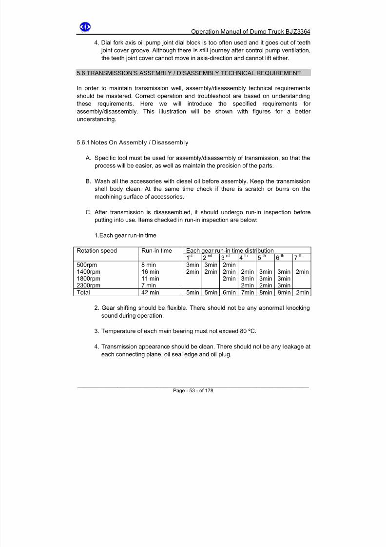
8/18/2019 d20 Bjz3364 Op Manual
http://slidepdf.com/reader/full/d20-bjz3364-op-manual 63/188
Operation Manual of Dump Truck BJZ3364
4. Dial fork axis oil pump joint dial block is too often used and it goes out of teeth
joint cover groove. Although there is still journey after control pump ventilation,
the teeth joint cover cannot move in axis-direction and cannot lift either.
5.6 TRANSMISSION’S ASSEMBLY / DISASSEMBLY TECHNICAL REQUIREMENT In order to maintain transmission well, assembly/disassembly technical requirements
should be mastered. Correct operation and troubleshoot are based on understanding
these requirements. Here we will introduce the specified requirements for
assembly/disassembly. This illustration will be shown with figures for a better
understanding.
5.6.1 Notes On Assembly / Disassembly
A. Specific tool must be used for assembly/disassembly of transmission, so that the
process will be easier, as well as maintain the precision of the parts.
B. Wash all the accessories with diesel oil before assembly. Keep the transmission
shell body clean. At the same time check if there is scratch or burrs on the
machining surface of accessories.
C. After transmission is disassembled, it should undergo run-in inspection before
putting into use. Items checked in run-in inspection are below:
1.Each gear run-in time
Each gear run-in time distributionRotation speed Run-in time
1st 2
nd 3
rd 4
th 5
th 6
th 7
th
500rpm1400rpm1800rpm2300rpm
8 min16 min11 min7 min
3min2min
3min2min
2min2min2min
2min3min2min
3min3min2min
3min3min3min
2min
Total 42 min 5min 5min 6min 7min 8min 9min 2min
2. Gear shifting should be flexible. There should not be any abnormal knocking
sound during operation.
3. Temperature of each main bearing must not exceed 80 ºC.
4. Transmission appearance should be clean. There should not be any leakage at
each connecting plane, oil seal edge and oil plug.
______________________________________________________________________ Page - 53 - of 178

8/18/2019 d20 Bjz3364 Op Manual
http://slidepdf.com/reader/full/d20-bjz3364-op-manual 64/188
Operation Manual of Dump Truck BJZ3364
D. Due to large impact on transmission during work, when assembling fasten bolt,
tighten the bolt according to screw down moment. Bolt with lead thread lock wire
must be locked well so that it will not loose. Below is transmission fasten bolt screw
down moment and their position:
Fasten parts name and position Specification Screw down moment
Axis two bearing shell fasten bolt
Front shell compression bolt
Front shell & shell body combinationbolt
Shell body & rear shell combinationbolt
Rear shell fixed lifting pump bolt
Rear upper & lower shelf and rearshell fixed bolt
Upper shell circumjacent fasten bolt
Upper shell fixed control axis supportbolt
Dial fork support and shell bodycombination bolt
Gear shifting fork positioning stop bolt Conductor move-up bolt
M14×120
M12×50M12×55
M18×100
M10×30
M12×45
M16×70
M10×65M10×110
M8×25
M10×30
M10×18
M10×15
137-167Nm
59Nm
196Nm
39Nm
59Nm
147Nm
40Nm
30Nm
40Nm
30Nm
30Nm
______________________________________________________________________ Page - 54 - of 178

8/18/2019 d20 Bjz3364 Op Manual
http://slidepdf.com/reader/full/d20-bjz3364-op-manual 65/188
Operation Manual of Dump Truck BJZ3364
5.6.2 Transmission Sub-assembly Assembly / Disassembly Technical
Requirements
Instructions with bracket are data for overdrive transmission. Instructions without bracket
are data for standard transmission.
Output End
+ 0 . 4 T o 0 . 5 m m
Input End
Figure 25 - Middle Axis Sub-assembly
1. Nominal common line dimension 91.5-0.125-0.210 /7 ( 91.36
-0.11-0.175/7 )
2. Nominal common line dimension 66.01-0.11-0.175/5 ( 71.08
-0.125-0.210 /6 )
3. Nominal common line dimension 70.88-0.11-0.175/5 ( 70.95
-0.11-0.175/6 )
______________________________________________________________________ Page - 55 - of 178

8/18/2019 d20 Bjz3364 Op Manual
http://slidepdf.com/reader/full/d20-bjz3364-op-manual 66/188
Operation Manual of Dump Truck BJZ3364
4. Nominal common line dimension 47.95-0.11-0.175/3 ( 48.10
-0.11-0.175/3 )
5. Nominal common line dimension 48.33-0.09-0.148/3
6. Nominal common line dimension 48.83-0.087-0.145 /3
7. 92312 bearing
8. Middle axis assembly inside the shell should have 0.4-0.5 mm clearance in
axis-direction, adjust using rear shell inner adjusting gasket. It is used mainly to
solve the problem of expansion and contraction of middle axis due to thermal
expansion, prevent damage of rear shell and bearing.
9. Non-straight tolerance of middle axis here: maximum curving degree measured
should not exceed 0.15mm.
10. 92215 bearing.
11. Loose 3rd 4 th 5 th 6 th gear’s gear on middle axis should not have clearance in
axis-direction. Use this adjusting gasket to adjust (must not use soft steel gasket or
copper gasket). It is done to enhance middle axis anti-bending intensity and
prevent overheat and jumping of 92215 bearing.
12. 92312 bearing.
______________________________________________________________________ Page - 56 - of 178

8/18/2019 d20 Bjz3364 Op Manual
http://slidepdf.com/reader/full/d20-bjz3364-op-manual 67/188
Operation Manual of Dump Truck BJZ3364
42208 Bearin g
4 To 4.5mm
Figure 26 - Reverse Gear Axis Sub-assembly
1. Nominal common line dimension 46.7-0.125-0.190 /3.
2. 42208 bearing.
3. No clearance is allowed for other parts on axis. Use this gasket to adjust.
4. Reverse gear bearing blocking cover is closely attached to inner circle of twobearings to maintain 0.2-0.3 mm axis-direction clearance in reverse gear’s gear.
However, no clearance is allowed in other parts on axis. This is done so to prevent
friction between bearing bead side surface and rolling path, reduce heat produced.
______________________________________________________________________ Page - 57 - of 178
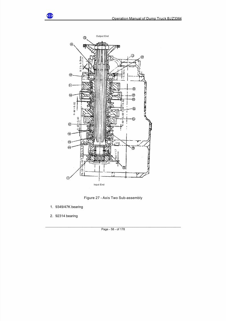
8/18/2019 d20 Bjz3364 Op Manual
http://slidepdf.com/reader/full/d20-bjz3364-op-manual 68/188
Operation Manual of Dump Truck BJZ3364
Output End
T o
T o
N o t < 1 . 7
T o
Input End
Figure 27 - Axis Two Sub-assembly
1. 9349/47K bearing
2. 92314 bearing
______________________________________________________________________ Page - 58 - of 178

8/18/2019 d20 Bjz3364 Op Manual
http://slidepdf.com/reader/full/d20-bjz3364-op-manual 69/188
Operation Manual of Dump Truck BJZ3364
3. Rolling needle ring’s each side is installed with 43 6.1×8 rolling needles. Must not
be less than that, or else rolling needle will be slanted and cannot rotate, heat will
be produced. Each group of rolling needles’ diameter tolerance is 0.005 so that the
difference between diameters is small enough for self rotation.
4. Joint teeth’s side face meshing clearance should be less than 0.6 mm and when
teeth width abrasion length exceed 20% of whole length, replace it.
5. Each gear rolling needle ring nominal diameter isΦ77.8-0.012-0.032
6. 9242/100 rolling needle bearing.
7. 9243/100 rolling needle bearing.
8. 192314 bearing’s axis-direction windage should not exceed 0.22mm. If exceeding
too much, axis two will jump in axis-direction.
9. Axis two loose teeth hub and rolling neilsbed should not have axis-direction
clearance, but leave 0.1-0.2mm clearance in front of blocking cover, use gasket to
adjust. The existence of this clearance is to prevent heating of bearing if 192314
bearing axis-direction clearance is gone. Take note: when axis two flange nut is
compressed, axis-direction thrust produced is transmitted to axis two itself through
half circle collar, and this has nothing to do with the 0.1-0.2mm clearance in front of
blocking cover.
10. M48×1.5 flange nut tighten torque is 392-785Nm.
11. Gasket slice used for adjusting axis-direction clearance (must not use soft steel
gasket or copper gasket instead) to prevent crush or distortion during power
transmission.
12. Axis two assembly should not move around inside body shell, use rear shell
stopping jaw inner adjusting gasket slice to adjust. It is better to have 0.05mm
surplus when two sides stick together. If axis two moves around too much, I will
crack rear shell and cause oil leakage and clashes between teeth cover and each
gear’s joint teeth side surfaces. Axis tow bearing cover’s bolt will become loose and
axis two will start jumping.
13. Nominal common line dimension 83.46-0.142-0.227 /5
14. Each gear’s gear nominal aperture Φ90+0.35
15. Nominal common line dimension 85.24-0.142-0.229 /5
16. Nominal common line dimension 85.29-0.125-0.210 /5
______________________________________________________________________ Page - 59 - of 178

8/18/2019 d20 Bjz3364 Op Manual
http://slidepdf.com/reader/full/d20-bjz3364-op-manual 70/188

8/18/2019 d20 Bjz3364 Op Manual
http://slidepdf.com/reader/full/d20-bjz3364-op-manual 71/188

8/18/2019 d20 Bjz3364 Op Manual
http://slidepdf.com/reader/full/d20-bjz3364-op-manual 72/188
Operation Manual of Dump Truck BJZ3364
Figure 30 - Rear Shell Sub-assembly
1. Odograph gear central distance is adjustable and it is adjusted by left-right
off-center plug. Its speed ratio range is adjustable. For this vehicle the speed ratio
is 1:3.3.
2. SG85x110x12 framework type oil seal. Replace the oil seal for every
assembly/disassembly.
3. 208 bearing.
4. The direction of oil pump joint axis’ mesh cover must not be mistaken, otherwise
because L journey is guaranteed; dial fork axis will rupture due to tweaking of root
part.
______________________________________________________________________ Page - 62 - of 178

8/18/2019 d20 Bjz3364 Op Manual
http://slidepdf.com/reader/full/d20-bjz3364-op-manual 73/188

8/18/2019 d20 Bjz3364 Op Manual
http://slidepdf.com/reader/full/d20-bjz3364-op-manual 74/188

8/18/2019 d20 Bjz3364 Op Manual
http://slidepdf.com/reader/full/d20-bjz3364-op-manual 75/188
Operation Manual of Dump Truck BJZ3364
Figure 32 - Upper Shell Sub-assembly
1. Ventilating cap must not be jammed; otherwise there will be leakage on oil seal
edge.
2. Make sure that the distance between 949/22k bearing end surface and gasket sliceend surface is 15mm, otherwise bearing will be scratched when gear shifting
control axis moves.
3. 949/22k bearing.
4. Gear shifting control axis dial head should coincide with gear shifting control axis
arm center line so that the forward and backward moving distances of gear shifting
handle are the same and it will not touch driver’s seat.
5. 949/22k bearing.
6. Please refer to the name plate speed ratio to identify to type of transmission
(standard or overdrive).
______________________________________________________________________ Page - 65 - of 178

8/18/2019 d20 Bjz3364 Op Manual
http://slidepdf.com/reader/full/d20-bjz3364-op-manual 76/188
Operation Manual of Dump Truck BJZ3364
Furcation Nut
Figure 33 - Control Pump Sub-assembly
1. Under normal condition this nut should be tightened to root of wire knot to
guarantee 29mm journey. Due to vibration and inner spring pressure effect,
unlocking may occur and 29mm journey will be changed. It will in turn leads to oil
pump connecting dial block’s abrasion and running out of mesh cover groove.
2. After inflation of control pump, mesh cover cannot be mounted on it. Do not adjust
by changing the length of furcation nut because it does not change 29mm journey,
instead it will only causes dial block’s abrasion.
______________________________________________________________________ Page - 66 - of 178

8/18/2019 d20 Bjz3364 Op Manual
http://slidepdf.com/reader/full/d20-bjz3364-op-manual 77/188
Operation Manual of Dump Truck BJZ3364
Control Pump Assembly
Dial Fork Axis Arm
Dial Fork Axis
Dial Block
Mesh Cover
Figure 34 - Lifting Pump Control Mechanism
1. Initial position is required when dial fork axis, dial fork axis arm and control pump
are assembled together, such that the clearance between dial block and mesh
cover’s each edge of two sides is 0.25mm, otherwise due to the spring effect in the
control pump, dial block will touch one side and cause abrasion. There will even be
noise if the situation is very serious.
2. Micro regulation can be implemented for furcation nut so that the initial position
requirement can be fulfilled.
3. 208 bearing.
______________________________________________________________________ Page - 67 - of 178

8/18/2019 d20 Bjz3364 Op Manual
http://slidepdf.com/reader/full/d20-bjz3364-op-manual 78/188
Operation Manual of Dump Truck BJZ3364
Chapter 6
Transmission Shaft
6.1 SUMMARY AND TECHNICAL DATA 6.1.1 Technical Data
6.1.1.1 Middle Transmission Shaft Belt Gimbal Assembly
Sustain working torque - 1020Nm
Spline specification - 10-50×38×6
Gimbal cross axis assembly dimension - Φ5O×135
Installation dimension - 447.7mm
Maximum stretching length - 20.5mm
Maximum shortening length - 20.5mm
6.1.1.2 Rear Axis Transmission Shaft Belt Gimbal Assembly
Sustain working torque - 6570Nm
Spline specification - 16-60×74×5
Gimbal cross axis assembly dimension - Φ89×10
Installation dimension - 1046mm
Maximum stretching length - +43mmMaximum shortening length - -55mm
6.2 TRANSMISSION SHAFT FUNCTION
The function of transmission shaft is to connect parts with non-homocentric and transmit
power. Usually the connection between each part is not on the same straight line; instead
it changes position accordingly during operation.
Transmission shaft is to transmit torque, meanwhile it solves the problem of each joint part
not homocentric and the distance between them is constantly changing. Hence, it is
necessary to make transmission shaft flexible. When relative contraposition happens
between two parts (engine and transmission or transmission and rear axis), they can still
rotate.
______________________________________________________________________ Page - 68 - of 178

8/18/2019 d20 Bjz3364 Op Manual
http://slidepdf.com/reader/full/d20-bjz3364-op-manual 79/188

8/18/2019 d20 Bjz3364 Op Manual
http://slidepdf.com/reader/full/d20-bjz3364-op-manual 80/188
Operation Manual of Dump Truck BJZ3364
6.3.2 Rear Axis Transmission Shaft Belt Gimbal Assembly
Refer to Figure 36 for its configuration. It connects transmission and rear axis. Its axis
angle is 3.07 º.
Figure 36 - Rear Axis Transmission
1 Rear axis transmission shaft
2 Rear axis transmission shaft tube fork assembly
3 Rear axis transmission shaft gimbal protruding edge
4 Gimbal cross axis belt bearing assembly
5 Gimbal bearing cover board
6 Gimbal bearing cover board bolt lock
7 Hexagonal head bolt
8 Gimbal tube fork oil seal gasket ring9 Gimbal tube fork oil seal
10 Gimbal tube fork oil seal cover
11 Balance slice
This vehicle is assembled with two gimbals in series. When assembling, make the 1 st
gimbal’s driven fork and the 2nd
gimbal’s driving fork on the same plane, meanwhile make
2 gimbals’ joint axis angle same, so that output axis’ rotation speed is equal to input axis’
rotation speed, as shown in Figure 37.
Figure 37 - Transmission Principle
______________________________________________________________________ Page - 70 - of 178

8/18/2019 d20 Bjz3364 Op Manual
http://slidepdf.com/reader/full/d20-bjz3364-op-manual 81/188
Operation Manual of Dump Truck BJZ3364
6.4 TRANSMISSION SHAFT ASSEMBLY AND OPERATION
In order to ensure normal working of transmission shaft and lengthen its lifespan, take
notes of the following points during assembly:
A. In order to ensure that transmission shaft input’s rotation speed is the same as
output rotation speed, transmission’s two ends’ gimbal forks should be on the same
plane, meanwhile in order to maintain the accurate dynamic balance of
transmission shaft, tube fork and splines axis are marked by arrow, when
assembling must aim at the arrow.
B. Causes of breakdown of transmission shaft dynamic balance:
1. Axis tube curving rolling needle bearing cover becomes loose or
transmission’s two ends gimbal forks are not on the same plane. Must repair
it, otherwise it will shake vigorously, affect the whole transmission system
and damage accelerating parts.
2. Balance slice falls off during operation due to loose welding of balance slice.
C. Middle transmission shaft tube fork should be installed on the side of clutch. Rear
transmission shaft tube fork should be installed on the side of transmission. This is
to ensure that the tube fork jaw inclines downwards to prevent water or dust fromcoming in.
6.5 TRANSMISSION SHAFT MAINTENANCE
6.5.1Lubrication
Serial
number
Lubrication location Interval
123
Middle transmission shaft tube fork oil injector Rear axis transmission shaft tube fork oilinjectorGimbal cross axis oil injector
Every 50 hoursNote: do notadd too muchbutter
6.5.2 Check-up
After the first 50 hours, check if joint flange’s fixed bolt is loose for every 400 hours.
______________________________________________________________________ Page - 71 - of 178

8/18/2019 d20 Bjz3364 Op Manual
http://slidepdf.com/reader/full/d20-bjz3364-op-manual 82/188
Operation Manual of Dump Truck BJZ3364
6.6 TRANSMISSION SHAFT BREAKDOWN ANALYSIS AND TROUBLESHOOTING
Malfunctions Causes Troubleshoot
Joint plane abrased Loose bolts, surface phasemovement Wipe clean using sand paperand repair the joint surfaceusing file, restore it and tightenthe bolt.
Transformation oftransmission shaft tube
Occasional external causesor irregular movement oftransmission system
Find the balance or replacethe tube
1. Transmission shaft losesbalance
______________________________________________________________________
Find the balance
2. Bad lubrication onbearing, oil injector
jammed
Replace oil injector or cleanthe jam
Cross axis and bearingabrasion
3. Clearance betweenbearing two end surfacedoes not meetrequirement. Too tight,heat produced whenrotating and abrasion ofrolling needle and bearing
Clearance should be0.015-0.14mm as required
Gimbal cover fork getsstuck
Oil seal is not tight enoughand water with impuritiescomes in or lack oflubrication grease
Oxidation of spline groove.Replace oil seal, filing withsand paper
1. Abrasion of bearing orcrack of rolling needle
Replace bearing
2. Clearance between splineaxis and tube fork is toolarge
Replace the abrading parts
Transmission shaftvibration is too noisy
3. Parts lose balance Find the balance
Page - 72 - of 178

8/18/2019 d20 Bjz3364 Op Manual
http://slidepdf.com/reader/full/d20-bjz3364-op-manual 83/188
Operation Manual of Dump Truck BJZ3364
Chapter 7
Rear Axis
7.1 SUMMARY AND TECHNICAL DATA
Rear axis consists of:
A. Rear axis casing belt half bearing tube assembly
B. Rear axis main reducer assembly
C. Rear axis differential assembly
D. Rear wheel planetary reducer assembly
Refer to Figure 38 for configuration.
______________________________________________________________________
Figure 38 - Rear Axis Configuration
Page - 73 - of 178

8/18/2019 d20 Bjz3364 Op Manual
http://slidepdf.com/reader/full/d20-bjz3364-op-manual 84/188

8/18/2019 d20 Bjz3364 Op Manual
http://slidepdf.com/reader/full/d20-bjz3364-op-manual 85/188
Operation Manual of Dump Truck BJZ3364
7.3 REAR AXIS ASSEMBLY AND REGULATION
7.3.1 Main Reducer Assembly And Regulation
Main reducer configuration. As shown in Figure 39.
Figure 39 - Main Reducer Configuration
1. Cone driving and driven gears installed in main reducer are pre-matched and
pre-labeled, they are not separately exchangeable. In order to adjust cone driving
gear bearing shell’s 7618 and 7614 two bearings’ elasticity so that the two bearings
can bear with the load together, a proper adjusting gasket slice installed in front
bearing inner ring and cone driving gear protruding shoulder end surface should be
chosen.
Firstly measure the dimension A according to Figure 40, dimension B from Figure
41 and dimension C from Figure 42, then refer to Figure 43, follow the equation
X=A-B-C to get the adjusting gasket slice’s thickness.
The thinnest gasket slice has thickness 0.05, so after calculating the axis-direction
allowable clearance should be less than 0.05. Gasket slice’s thickness can be 0.05,
0.10, 0.30 and 0.50. Fasten the groove nuts with joint axis and 686-883 Nm torque.
Compaction force should not be transmitted to bearing beads.
Cone driving gear should be agile and rotation torque should not bigger than 7 Nm
(oil seal friction torque is not counted and no axis-direction jump when manually
pushing).
______________________________________________________________________ Page - 75 - of 178

8/18/2019 d20 Bjz3364 Op Manual
http://slidepdf.com/reader/full/d20-bjz3364-op-manual 86/188
Operation Manual of Dump Truck BJZ3364
Figure 40 Figure 41 Figure 42
Figure 43 - Cone Driving Gear Bearing Shell Assembly
2. After the adjustment of cone driving gear bearing shell assembly is finished, in
order to satisfy the requirement for clearance of cone driving and driven gear
contacting area and teeth side, when installing cone driven gear and driving
cylindrical bevel wheel into main reducer shell, no axis-direction clearance is
allowed in between the two. Refer to Figure 39.
Axis two ends 7613 and 7618 bearing’s elasticity is decided by choosing
appropriate adjusting gasket slice thickness from two groups, and separately
installed into reducer outer shell’s left and right cover.
Inside each group there should be at least one slice with thickness 0.05 and 0.1mm,
the rest should follow the requirements. Usually first align with cone driving and
driven gear back cone surface, i.e. the cone distance joints of two cone gearscoincide at a point, then adjust accordingly.
______________________________________________________________________ Page - 76 - of 178

8/18/2019 d20 Bjz3364 Op Manual
http://slidepdf.com/reader/full/d20-bjz3364-op-manual 87/188
Operation Manual of Dump Truck BJZ3364
After the adjustment of the bearing, when singly rotating cone driven gear, the
rotation torque should not be larger than 7 Nm. When measuring power torque,
bearing should be lubricated, and measure only after gear rotates continuously in
one direction no less than 5 rounds.
3. Adjustment of cone driving and driven gear contacting area and teeth side’s
clearance. Apply a layer of red lead oil on cone driven gear’s teeth surface, and
rotate when no load in two directions.
Greason type: required to control the driven gear convexity contacting print within
the teeth central area (lean to small end), with distance 2-7 mm to small end.
Contacting area dimension is usually 1/2-5/8 of teeth height and teeth length.
Non-working surface should be controlled within teeth’s central area. Cone driven
gear’s correct contacting situation is shown in Figure 44.
Teeth side c learance adjustment
______________________________________________________________________ Page - 77 - of 178

8/18/2019 d20 Bjz3364 Op Manual
http://slidepdf.com/reader/full/d20-bjz3364-op-manual 88/188
Operation Manual of Dump Truck BJZ3364
2 - 7mm
0.8 ~ 1.6mm
Figure 44 - Cone Driven Gear Contact
Fig A: contacting area condition of adjustment of driven cone gear during assembly.
Fig B: contacting area changing condition of driven cone gear under load condition.
Cone driving and driven gear mesh teeth side clearance is 0.25-0.35mm. This is under the
consideration of oil saving and prevention of dead bite of mesh gear when thermal
expansion.
It is required to measure 3-4 different positions within one week. When incorrectcontracting area and teeth side clearance are found during installation of driving and
driven cone gear, adjust according to the methods shown in Figure 44. (Figure 44 shows
driven large gear contacting surface).
Adjusting formula: larger follow in, small follow out, head main in, root main out.
Driving cone gear’s front and rear direction adjustment is done by adjusting gasket slice
on cone driving gear bearing shell assembly and main reducer shell contacting stop jaw
circle.
Driven cone gear’s left and right adjustment is done by two groups of gasket slices on
main reducer shell left and right shell (inside and below). Under normal situation: the
gasket reduced from one side is just the gasket added on the other side. Do not add or
reduce gasket slices so that the axis-direction clearances of two end bearings remain
constant.
______________________________________________________________________ Page - 78 - of 178

8/18/2019 d20 Bjz3364 Op Manual
http://slidepdf.com/reader/full/d20-bjz3364-op-manual 89/188
Operation Manual of Dump Truck BJZ3364
7.3.2 Differential Assembly And Adjustment
Differential’s configuration is shown in Figure 45.
Figure 45 - Differential configuration
1 Hexagonal groove nut 7 Rear axis differential shell
2 Uncork pin 8 Planetary gear gasket slice
3 Hole bolt 9 Half axis gear and planetary gear
4 7521 cone roller bearing 10 Half axis gear gasket slice5 Adjusting nut 11 Cross axis
6 Cylindrical pin 12 Driven cylindrical bevel wheel
Differential is a simple symmetrical straight teeth cone type. It consists of half axis gear,
planetary gear, cross axis, differential shell and gasket slice. Cross axis is separating type.
There is a spline hole in the middle of half axis gear, and it is connected to half axis
involute spline respectively.
When vehicle is running on a smooth and straight road, the resistance on the two wheel
are almost the same, and the rotation speeds are the same, differential inner planetary
gear and half axis gear are rotated by differential shell led by driven cylindrical bevel wheel,
and so drive the vehicle.
When vehicle is turning, resistances on inner and outer wheels are different, and the paths
they go through are with different distances. Two half axis gear produce relative rotation
speed difference though planetary gear’s rotation to complete the speed difference effect
when turning.
______________________________________________________________________ Page - 79 - of 178

8/18/2019 d20 Bjz3364 Op Manual
http://slidepdf.com/reader/full/d20-bjz3364-op-manual 90/188

8/18/2019 d20 Bjz3364 Op Manual
http://slidepdf.com/reader/full/d20-bjz3364-op-manual 91/188
Operation Manual of Dump Truck BJZ3364
7.3.3 Rear Wheel Planetary Reducer’s Assembly And Adjustment
Rear wheel planetary reducer is straight teeth planetary gear transmission device and is
installed inside the wheel hub. Refer to Figure 38. Sun gear is fastened on the half axis by
spline which meshes with 4 planetary gears. Inner gear is fastened on half axis tube byconnecting inner gear shell. Planetary gear seat is fastened on rear wheel hub using
double head bolt. When sun gear rotates, planetary rotates immediately around sun gear.
Planetary gear’s rotation again will lead to the rotation of planetary gear seat through
planetary gear axis. The rotation of planetary gear seat is just the rotation of wheel.
1. Rear wheel planetary reducer’s inner gear is fastened on half axis tube through
inner gear shell and four C16×50 flat key.
2. Four C16×50 flat keys inlayed on half axis tube and inner gear shell inner hole key
groove should have tight conjugation and should not have looseness, otherwise
force is not evenly distributed when transmitting power.
3. When assembling rear wheel planetary reducer inner gear, check the radial runout
tolerance of inner gear, usually it should not exceed 0.22mm. If inner gear radial
runout is too much, it will affect four planetary gear’s power distribution, causing
early stage damage of planetary roller needle.
4. The adjustment of clearance between half axis stop push bolt and half axis end
surface: screw down half axis stop push bolt and make it touch half axis endsurface till cannot screw down further, then withdraw the half axis stop push bolt by
one buckle, and tighten using nut. The axis direction clearance between half axis
end surface and half axis stop push bolt is 1.5mm.
______________________________________________________________________ Page - 81 - of 178

8/18/2019 d20 Bjz3364 Op Manual
http://slidepdf.com/reader/full/d20-bjz3364-op-manual 92/188
Operation Manual of Dump Truck BJZ3364
7.4 REAR AXIS BREAKDOWN ANALYSIS AND TROUBLESHOOTING
Malfunction Causes Troubleshoot
Constant noise 1. Abrasion of bearing
2. Bad lubrication
3. Abrasion of gear teeth4. Driving and driven gear
mesh position andclearance not suitable
1. Check or replace
bearing2. Check oil level makesure it is sufficient
3. Replace worn gear4. Re-adjust
Discontinuous noise 1. Wheel bearing clearancetoo large
2. Improper cylindrical gearinstallation
3. Cone gear bearingclearance too large
4. Wheel imbalance orimproper assembly
1. Re-adjust
2. Check and adjust orreplace
3. Re-adjust
4. Install correctly so itis parallel
Periodic noise 1. Differential gets stuck2. Abrasion of planetary gear
and half axis gear teeth3. Differential parts
coordinating clearance toolarge
1. Check or replace2. Change abraded
gears3. Re-adjust
When accelerating or
decelerating silveryknock can be heard
1. Improper adjustment of rear
wheel planetary reducer2. Coordinating clearance too
large
1. Check or replace
2. Re-adjust
7.5 REAR AXIS MAINTENANCE
1. After run-in period, replace the lubricants for every 800 hours travel. Oil brand is
#22 synthesize gear oil. When replacing lubricants, oil should be discharged when
it is still hot, and clean the scrap iron on permanent magnet of oil discharge plug.
After new vehicle’s run-in, when replacing oil for the first time, dilute machine oil
should be added in after deposed oil is discharged (better use #5 high speed
machine oil – SYB1101-62), the amount added in should be about 2/3 of main
reducer’s capacity. Lift up rear wheels, start the engine and run for about 5 minutes,
discharge the cleaning machine oil, and then add in #22 synthesize gear oil.
2. Check the volume of lubricants for every 100 hours travel.
3. When adding oil, use oil level indicator to control the oil level of main reducer. When
adding oil for wheel hub, open the screw plug 5. Add oil till it overflows.
4. Check the tightness of bolt regularly.
5. Wash and replace oil for wheel hub bearing for every 40 hours travel. If there is oil
leakage, first check oil seal. If oil seal is fine, then check if ventilating cap is stuck.
______________________________________________________________________ Page - 82 - of 178

8/18/2019 d20 Bjz3364 Op Manual
http://slidepdf.com/reader/full/d20-bjz3364-op-manual 93/188

8/18/2019 d20 Bjz3364 Op Manual
http://slidepdf.com/reader/full/d20-bjz3364-op-manual 94/188

8/18/2019 d20 Bjz3364 Op Manual
http://slidepdf.com/reader/full/d20-bjz3364-op-manual 95/188
Operation Manual of Dump Truck BJZ3364
Figure 47 - Front Wheel Configuration
1 Front axis tube 11 Brake firm
2 Turning transverse puller assembly 12 Wheel
3 Front axis spring support 13 Front wheel hub
4 Turning straight puller assembly 14 Knuckle axis lock tight nut
5 Turning straight puller arm 15 Front wheel hub cover
6 Brake bracket 16 Knuckle upper gasket slice
7 Knuckle pin 17 Knuckle arm
8 Knuckle lock bolt 18 Front axis head
9 Knuckle seat 19 Front thrust pole pin axis cover10 Knuckle axis
______________________________________________________________________ Page - 85 - of 178

8/18/2019 d20 Bjz3364 Op Manual
http://slidepdf.com/reader/full/d20-bjz3364-op-manual 96/188
Operation Manual of Dump Truck BJZ3364
8.4 FRONT AXLE BREAKDOWN ANALYSIS AND TROUBLESHOOTING
Malfunction Causes Troubleshoot
Swing of front wheel 1.Abrasion of knuckle pin stop
push bearing2.Abrasion of turning puller ballbowl
3.Bad adjustment of wheel bearing4.Front wheel toe changes
5.Looseness of joints betweenturning droop arm and turningpuller
6.Looseness of turning parts
1. Replace wearing
parts2. Replace wearingparts
3. Re-adjust
4. Re-adjust andfasten well
5. Re-tighten,eliminate clearance
6. Check and tighten
Heavy turning 1. Wrong installation of turningmachine sliding valve in piston
2. Stuck and lag in steering wheelthread bar
3. One front wheel brake does notrestore its position
4. Unequal tightness of two frontwheel bearings
5. Pressure difference too large
between two wheel
1. Re-adjust
2. Check andeliminate the stuckand lag
3. Repair parts whichdo not restoreposition
4. Re-adjust bearings
5. Increase pressure
according therequirements
Deflection duringdriving
1. Too much abrasion of wheel2. Lag in brake of one wheel
3. Insufficient pressure of one tyre
4. One tyre’s bearing too tight
1. Replace the tyre2. Eliminate the
lagging part3. Increase pressure
according torequirements
4. Re-adjust bearingclearance
Swaying sideways 1. Front axis not straight2. Unequal pressure in tyres
3. Unequal abrasion of tyres4. Too large clearance between
wheel bearings5. Looseness in steel board
spring bolt6. Shock absorber not working
1. Rectify front axis2. Make pressure
equal3. Replace tyres4. Re-adjust
5. Fasten steel boardbolt
6. Check and replaceshock absorber
______________________________________________________________________ Page - 86 - of 178
8/18/2019 d20 Bjz3364 Op Manual
http://slidepdf.com/reader/full/d20-bjz3364-op-manual 97/188
Operation Manual of Dump Truck BJZ3364
8.5 FRONT AXLE MAINTENANCE
A. Often check the clearance between knuckle seat and front axis head. If the
clearance if larger than 0.2mm, adjust till it is within 0.1mm.
B. Often check the ball pin of transverse and straight puller, it should be turnedarduously by manual and no lag. Take note that it must not be too loose.
C. After run-in and 400 hours travel, wash the wheel hub bearing and replace new #2
lithium base lubricating grease. Apply the lubricating grease periodically onto the
grease jaw.
D. After 400 hours travel, must re-tighten all the joint parts.
______________________________________________________________________ Page - 87 - of 178

8/18/2019 d20 Bjz3364 Op Manual
http://slidepdf.com/reader/full/d20-bjz3364-op-manual 98/188
Operation Manual of Dump Truck BJZ3364
Chapter 9
Steering System
9.1 SUMMARY AND TECHNICAL DATA
Droop arm angle : 90°
# circles of steering wheel : 5.82
# circles of steering wheel after adjustment : 4.875
Steering machine transmission ratio
When traveling on a straight line : 23.27
Maximum output torque of steering arm : 9635Nm (14Mpa)
9.1.1Steering System Summary
During traveling, vehicle needs to change its direction very often. Steering is done by
deflecting some certain angle of steering wheel (front wheel) on the ground. Steering
system is controlled by the driver. It is a system which makes steering wheel (front wheel)
deflects.
This vehicle has hydraulic pressure power assistance, so that labor intensity of driver is
greatly reduced and maneuverability of vehicle is greatly enhanced. When using power
steering, the push of front wheel steering mainly depends on hydraulic pressure. Thewhole steering procedure (including steering direction and steering angle) much obey the
driver’s operation. This power steering can satisfy the following requirements:
1. When it is not steering, it can automatically keep the front wheel in the middle position
and maintain the straight line travel of vehicle.
2. When steering, front wheel steering angle should be proportional to steering wheel’s
steering angle, the direction should be consistent as steering wheel.
3. Steering should be sensitive, short period of time for action lag, maximum steering
angle should be done within 2-3 seconds (equivalent to turning the steering wheel for
2-3 rounds).
4. Light and handy steering, but also have the road feeling. When driver controls the
vehicle to do steering, he should depend not only on the eyesight, but also the
condition of road resistance so that it will react to the steering wheel. Make sure that
the driver has a feel of the road inside his mind.
5. Prevent reverse impact. During the travel if front wheel clashes with barriers, the
impact transmitted to steering wheel should be as small as possible.
6. Ensure that the control valve can be automatically back to its right position and
prevent wheels from vibrating.
7. Good following actions.
8. Safe and reliable. When power steering is not functioning, steering can also be doneby manpower through mechanical system.
______________________________________________________________________ Page - 88 - of 178

8/18/2019 d20 Bjz3364 Op Manual
http://slidepdf.com/reader/full/d20-bjz3364-op-manual 99/188
Operation Manual of Dump Truck BJZ3364
9.1.2Steering Structure
Steering device consists of following parts (shown in Figure 48): power steering device,
steering oil pump, steering oilcan and steering oil pipe. Power steering device is theexecuting component for steering system hydraulic power assistance.
Steering oil pump and engine are connected to be the system’s hydraulic power source.
Steering oilcan can be used to store, cool down, filter and renew oil. Engine drives
steering oil pump directly, it sucks the oil from oil tank through oil suck pipe, and pump the
pressured oil to steering machine through high pressure oil pipe. The low pressure oil
coming out from the steering machine oil returning jaw will go back to oil tank through oil
returning pipe.
Steering Oil CanOil Return Pipe
Oil Input High PressurePipeOil Pressure Pipe
Steering
Steering Pump
Figure 48 - Steering
______________________________________________________________________ Page - 89 - of 178

8/18/2019 d20 Bjz3364 Op Manual
http://slidepdf.com/reader/full/d20-bjz3364-op-manual 100/188
Operation Manual of Dump Truck BJZ3364
9.2 WORKING PRINCIPLE
9.2.1 Middle Posit ion
When vehicle is traveling on a straight line (steering wheel is still), hydraulic oil from oil
pump enters the oil enter gate and passed through the pre-opening clearance of steering
valve. Because at the moment the steering valve is still, steering device’s two working
cavities will have the same oil pressure and no assistant power will be produced.
Hydraulic oil goes back to oil tank through oil returns gate.
9.2.2 Steering Process
When turning the steering plate, the pre-opening clearance between valve core and
steering screw is changed, so that oil pressure difference corresponding to steering
resistance is produced between two working cavities. This oil pressure difference
functions on steering nut (piston) and pushes steering nut (piston) to overcome steering
resistance and results in displacement, and brings along the arm axis to achieve power
assistance steering.
9.2.3 Position Return Process
When steering is done, force on steering plate disappears. Under the effect of power
steering device inner tweak pole and front wheel auto-return position torque, the oilpressure difference between steering device’s two working oil cavity is eliminated. Wheel
will be then on the straight line travel position till it goes back to the vehicle straight line
travel position.
______________________________________________________________________ Page - 90 - of 178

8/18/2019 d20 Bjz3364 Op Manual
http://slidepdf.com/reader/full/d20-bjz3364-op-manual 101/188
Operation Manual of Dump Truck BJZ3364
______________________________________________________________________
中间位置
右转向
左转向
去往上油缸 来自下油缸
去往下油缸 来自上油缸
To Upper Oil
TankFrom Lower OilTank 输入轴逆时
高压油
低压油
针旋转Input Axis, Anti -Clockwise Rotation
Left Rotation
Middle Position
To Upper OilTank
From Lower Oil
Tank输入轴顺时针旋转Input Axis, Clockwise
Rotation
High Pressure Oil
Low Pressure Oil
Right Rotation
Page - 91 - of 178

8/18/2019 d20 Bjz3364 Op Manual
http://slidepdf.com/reader/full/d20-bjz3364-op-manual 102/188
Operation Manual of Dump Truck BJZ3364
9.2.4 Road Feel Effect
“Road feel” is direct feel of road condition and resistance change through steering device
when driver is carrying out the action of steering. When the driver applies force on thesteering wheel, at the same time it is also applied on steering device’s tweak pole and
makes it retort and transform. Therefore transformation measure depends on wheel
steering resistance. When steering resistance is large, this transformation measure
increases also. Hence the driver can judge the change in steering resistance from the
force he applies on the steering wheel, and so to obtain “road feel” effect.
9.3 POWER STEERING PUMP
Power steering pump uses American Vickers company V20F series single line balance
constant current and pressure lamina pump. The model details are below:
Serial number: V20F 1P 6P 38C 6H 11
Explanation:
Lamina Pump Manufacturer DesignSerial Number
Serial Label
Embeded Flux Control AndOverflow Valve
Overflow Valve – Default Value2000psi
2 Bolt Flange
Throttle Hole Number Flux6-6USgpm
Oil Inlet Dimensi on ¼ NPT ScrewThread
Rated Flux – USgpmOil Exit And Enter On TheSame Side
Oil Outlet Dimension ¾ -16 StraightScrew Thread
Overflow Outlet Dimension 1/2’’ NPTScrew Thread
Axis Body Is Spline AxisConnection
Note: In the serial number, the second part of number is the pump’s flux and pressure.
______________________________________________________________________ Page - 92 - of 178
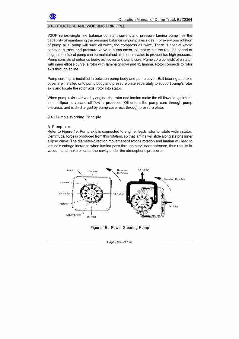
8/18/2019 d20 Bjz3364 Op Manual
http://slidepdf.com/reader/full/d20-bjz3364-op-manual 103/188
Operation Manual of Dump Truck BJZ3364
9.4 STRUCTURE AND WORKING PRINCIPLE
V2OF series single line balance constant current and pressure lamina pump has the
capability of maintaining the pressure balance on pump axis sides. For every one rotation
of pump axis, pump will suck oil twice, the compress oil twice. There is special wholeconstant current and pressure valve in pump cover, so that within the rotation speed of
engine, the flux of pump can be maintained at a certain value to prevent too high pressure.
Pump consists of entrance body, exit cover and pump core. Pump core consists of a stator
with inner ellipse curve, a rotor with lamina groove and 12 lamina. Rotor connects to rotor
axis through spline.
Pump core nip is installed in between pump body and pump cover. Ball bearing and axis
cover are installed onto pump body and pressure plate separately to support pump’s rotor
axis and locate the rotor axis’ rotor into stator.
When pump axis is driven by engine, the rotor and lamina make the oil flow along stator’s
inner ellipse curve and oil flow is produced. Oil enters the pump core through pump
entrance, and is discharged by pump cover exit through pressure plate.
9.4.1Pump’s Working Principle
A. Pump core
Refer to Figure 49. Pump axis is connected to engine, leads rotor to rotate within stator.
Centrifugal force is produced from this rotation, so that lamina will slide along stator’s innerellipse curve. The diameter-direction movement of rotor’s rotation and lamina will lead to
lamina’s cubage increase when lamina pass through curvilinear entrance, thus results in
vacuum and make oil enter the cavity under the atmospheric pressure.
Oil OutletRotationDirection
StatorOil Inlet
Rotation Direction
Lamina
Oil Outlet Oil Outlet
RotatorOil Inlet
Driving AxisOil Inlet
Figure 49 – Power Steering Pump
______________________________________________________________________ Page - 93 - of 178

8/18/2019 d20 Bjz3364 Op Manual
http://slidepdf.com/reader/full/d20-bjz3364-op-manual 104/188

8/18/2019 d20 Bjz3364 Op Manual
http://slidepdf.com/reader/full/d20-bjz3364-op-manual 105/188
Operation Manual of Dump Truck BJZ3364
D. Constant Current And Pressure Valve
The working principle of constant current and pressure valve is shown in Figure 51.
Figure 51 is whole constant current and pressure valve installed on pump cover, and is
used for restrict pump’s maximum flux and maximum system pressure.
1. Figure 51A shows the situation when pump constant current and pressure valve is
not functioning, all the oil from pump will flow into steering machine. Large spring
cavity is connected to pressure exit through damp hole, the oil pressure of cavity
and spring force is slightly larger than the oil pressure of slide valve on the other
side. When slide valve is closed, pump oil discharge and side open hole are sealed
by slide valve sealing surface.
2. Figure 51B shows the condition when flooding is functioning. When pump’s flux is
larger than assured value of measuring hole, the height of measuring hole front and
rear pressure cover will increase along with the increase of flux. When flux exceeds
the limit of measuring hole, the pressure difference will push slide valve to
overcome the spring force and open up the slide valve. Extra oil will flow to side
open hole through the clearance from opening slide valve.
3. Figure 51C shows the maximum pressure when system pressure exceeds
constant current and pressure valve’s limit. At this moment the valve needle for
stabilizing pressure will be open. The oil from large spring cavity will flow to side
open hole through the clearance from opening valve needle. The sudden pressuredecrease in this cavity will lead to increase in pressure difference between slide
valve right and left sides. This pressure difference will push the slide valve to the
left hand side and compress the large spring and open the slide valve. The oil from
right side of slide valve will flow to side open hole through the clearance from
opening slide valve.
______________________________________________________________________ Page - 95 - of 178

8/18/2019 d20 Bjz3364 Op Manual
http://slidepdf.com/reader/full/d20-bjz3364-op-manual 106/188
Operation Manual of Dump Truck BJZ3364
5 1 C - W h e n S y s t e m
P r e s s u r e I s O v e
r l o a d e d
T o O i l C a n
P r e s s u r e H o l e
F i g u r e 5 1 C
F i g u r e 5 1 – C o n s t a n t C u r r e n t A n d P r e s s u r e V a l v e P
r i n c i p l e
D
u e T o P r e s s u r e
D
e c r e a s e I n
M
e a s u r i n g H o l e ,
S
p r i n g C a v i t y
P
r e s s u r e I s L o w e r
T
h a n S y s t e m
P
r e s s u r e
E x t r a O i l
F l o w s T o
O i l c a n
T h r o u g h
C o n s t a n t
C u r r e n t V a l v e
T o O i l C a n
R e s i s t a n c e H o l e
S a
f e t y V a l v e
O v
e r l o a d V a l v e
N e
e d l e O p e n
5 1 B – N o r m a l O p e r a t i o n
F i g u r e 5 1 B
P r e s s u r e H o l e
S a f e t y V a l v e
S p r i n g
G o T o
P u m p
C o r e O i l
E x i t P i p e
M e a s u r i n g H o l e
C o n f i r m F l u x
S l i d e V a l v e C l o s e s O i l
C a n O p e n H o l e
F i g u r e 5 1 A
5 1 A – W h o l e C i r c u l a t i n g
S y s t e m U
n d e r L o w S p e e d
P r e s s u r e H o l e
T o O i l C a n
S a f e t y V a l v e
P r e s s u r e P a s s i n g
T h r o u g h D a m p H o l e
R i g h t S p r i n g
W h
e n P r e s s u r e O f
T w
o S i d e s E q u a l s ,
S p
r i n g K e e p s
C o
n s t a n t C u r r e n t
V a l v e C l o s e
______________________________________________________________________ Page - 96 - of 178
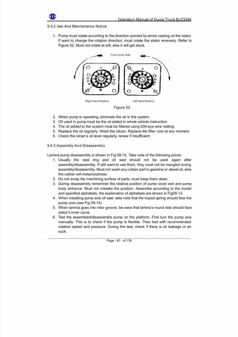
8/18/2019 d20 Bjz3364 Op Manual
http://slidepdf.com/reader/full/d20-bjz3364-op-manual 107/188
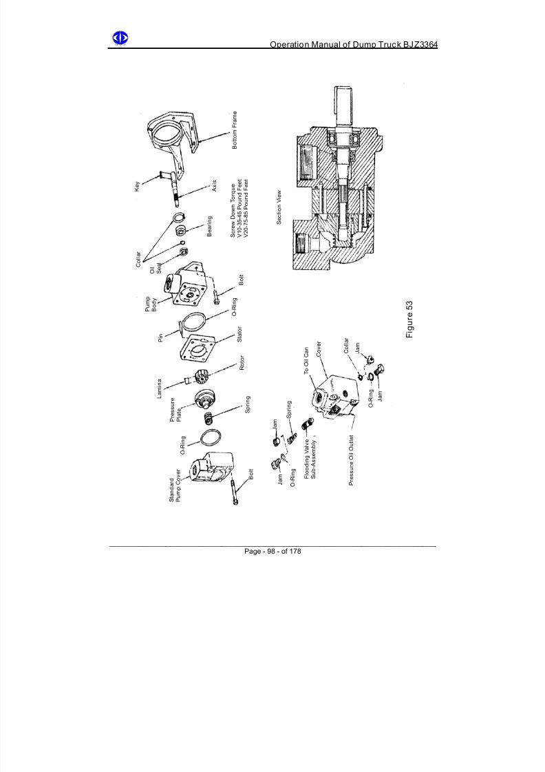
8/18/2019 d20 Bjz3364 Op Manual
http://slidepdf.com/reader/full/d20-bjz3364-op-manual 108/188
Operation Manual of Dump Truck BJZ3364
B o t t o m F r a m e
S c r e w D o w n T o r q u e
V 1 0 - 3 5 - 4 5 P
o u n d F e e t
V 2 0 - 7 5 - 8 5 P
o u n d F e e t
K e y
A x i s
S e c t i o n V i e w
B e a r i n g
C o l l a r
O i l S e a l
B o l t
P u m p
B o d y
F i g u r e 5 3
O - R i n g
S t a t o r
P i n
C o l l a r
J a m
C o v e r
T o O i l C a n
R o t o r
L a m i n a
O - R i n g
J a m
S p r i n g
P r e s s u r e
P l a
t e
S
p r i n g
J a m
P r e s s u r e O i l O u t l e t
O - R i n g
F l o o d i n g V a l v e
S u b - A s s e m b l y
B o l t
S t a n d a r d
P u m p C o v e r
O - R i n g
J a m
______________________________________________________________________ Page - 98 - of 178

8/18/2019 d20 Bjz3364 Op Manual
http://slidepdf.com/reader/full/d20-bjz3364-op-manual 109/188
Operation Manual of Dump Truck BJZ3364
A – opposite the oil inlet
B – from oil inlet anti-clockwise 90 º
C – on the side of oil inlet
D – from oil inlet clockwise 90 º
Hooped Spring
9.4.4 Malfunction Analysis And Troubleshooting
Malfunction Possible causes Troubleshoot
Mistake in pumpdriving direction
Immediately change driving direction toprevent pump getting stuck, Fig 09-11 showsthe right position of two rotation direction ring
Joint axis or pumpaxis cut
Disassemble pump, check pump axis andpump core to see if there is damage, replacewhen necessary
Oilcan oil exit getstuck
Check if there is dust or dirt in the filter core,wash if necessary
Oil too sticky cannotrenew
Change the oil throughout and replace theappropriate and filtered new oil
Slide valve or safetyvalve needle getstuck
When disassemble pump, wash the valve indetergents. Put valve back to valve cover,check if it gets stuck, use sandpaper to rub offthe granule on the surface, do not make valve
cylinder rim round or rub the cover inner hole,clean all parts and reassemble the oil pump
No oil comes outfrom pump
Rotor lamina getstuck into groove
Disassemble the pump and check for dirtsand metal crumbs, wash the partsthroughout, replace the broken parts, washthe system if necessary and change the oil
System pressurevalve (safety valve)it too low
Use manometer to adjustOil pressure nosufficient
Pump’s flux is lost 1 some valve get stuck and are always open,oil flows freely to oilcan
2 Oil entrance pipe of pressure pipe crack
______________________________________________________________________
Ax is Oil Seal(Spring Faces Inner Pump
Cover)
Pump Body(Oil InletReference)Standard
Exit Reference
Figure 54 Figure 55
Cover
Page - 99 - of 178

8/18/2019 d20 Bjz3364 Op Manual
http://slidepdf.com/reader/full/d20-bjz3364-op-manual 110/188
8/18/2019 d20 Bjz3364 Op Manual
http://slidepdf.com/reader/full/d20-bjz3364-op-manual 111/188
Operation Manual of Dump Truck BJZ3364
B. Check s teering Joint’s Reliability
Steering will shake due to looseness of joint bolts on steering machine support. Screw
down steering machine support and vehicle frame’s joint bolt and steering machine and itssupport’s joint bolt.
Bolt’s diameter is M20: the screw down torque of steering machine fixed on support is 441
Nm, and screw down torque of steering support fixed on the vehicle frame is 294 Nm.
Must not use usual linked wrench or uncork wrench to fasten, must use specific sleeve
wrench connecting to long pole to fasten (best to use torque force wrench).
C. Strict ly Prohibit “ Dead Wheel”
When steering machine is in its limit position or front wheel meets hard obstacles, strictly
prohibit turning the steering wheel by force, i.e. do not let steer wheel become “dead
wheel”. Must turn during traveling.
D.Beware Of Mixing Air Into Oil
If oil mixes with air, steering wheel will shake. Shaking of steering wheel means when
steering wheel is not given a steering instruction, it will suddenly shake randomly. This
natural shaking is unpredictable, and this malfunction is commonly called “steering wheel
hits hand”.
It is a special malfunction of power steering. This malfunction is dangerous, when it gets
serious it will injure the arm or wrist. Check immediately and do the necessary
troubleshooting.Due to the low condensability of oil, it usually can be ignored, but
condensability of air is larger and it is about one thousand times of oil, hence even there is
a small amount of air in the oil, it will have large influence. Under the impact of pressure oil,
air will soon be smashed into numerous air bubbles and mix into the oil (when low
pressure they will automatically be separated out).
Oil with air bubbles is very unstable, it becomes something similar to volatile “elastomer”,
sometimes it compresses and sometimes it expands, causing the change in cubage of
oilcan piston’s two sides, i.e. the position of piston is constantly changing.
Hence, it will lead to the swing of steering wheel thread bar connecting piston and slide
valve and steering wheel. This random and sudden impact of swing is steering wheel
shake, or commonly known as “steering wheel hits hand”.
It is relatively simple to solve this problem: find out where the air suck happens and causes
of it and get rid of them. If this malfunction happens, stop the vehicle and do the
troubleshoot.
______________________________________________________________________ Page - 101 - of 178

8/18/2019 d20 Bjz3364 Op Manual
http://slidepdf.com/reader/full/d20-bjz3364-op-manual 112/188
Operation Manual of Dump Truck BJZ3364
Check mainly the following parts:
1. Any damage in oil pump oil seal. Replace if there is.
2. Any looseness or loose seal or damage in oil suck pipe’s two connecting ends.
3. Oil level in the oil tank is too low. Renew it. Usually the oil level should be about 20
mm below the oil tank’s top.4. Oil suck pipe gets stuck, causing partial vacuum increase, increasing the possibility
of air suck.
E. Rightly Judge Steering Turning Standard (Light Or Heavy)
For this type of power steering, when difficulties are met in steering, it is not right to
generally say the steering is light or heavy. This is because it is different from mechanical
steering. In order to judge and eliminate the failure, two guild lines should be reflected for
judging the power steering: one is if there is difficulty in steering (whether the force applied
onto the steering wheel is light or heavy), another one is the possible gyration speed when
steer wheel is turning (speed of turning the steering wheel). Both situations are possible to
happen, i.e. it can be “slow turning is light, fast turning is heavy” or “both slow and fast
turnings are heavy”. The causes for these two situations are different but mainly because
of leakage of power steering oil pump’s oil pressure and flux and steering machine.
For a good steering machine, within 5 seconds the steering wheel can be turned from left
to right or right to left, rotation is about 4.875 rounds.
When traveling on a flat road, the normal turning force applied on steering wheel (not
including sharp turn) is about 49 N.
F. Strictly Prohibit Engine Flameout Or Slide With Neutral Gear
This is because hydraulic power steering is used. It prevents malfunction of hydraulic
power and danger when steering.
G. Operation And Adjustment Of Steering
In order to maintain safe and reliable working of steering machine, driver should fully
understand the structure and principle of steering machine, how to use and maintain.
1. This whole power steering machine uses normal current structure. It relies on
vehicle engine driving oil pump. Therefore, the vehicle must not slide with engine
flameout, otherwise the driver will not get used to the heavy steering due to engine
flameout.
2. If the steering system fails due to malfunction of oil pump and oil path, the steering
machine can be treated as mechanical steering machine, force steering till vehicle
reaches maintenance station. But do not force steering for a long time. Do not
overload the vehicle.
3. Make sure the inside of power steering system is clean. When renewing oil, do not
use unclean container to fill the oil. When disassembling and checking, do not put
the parts at will. Do not allow any sundries go into the system during assembly.System’s working oil level should not be lower than the standard.
______________________________________________________________________ Page - 102 - of 178

8/18/2019 d20 Bjz3364 Op Manual
http://slidepdf.com/reader/full/d20-bjz3364-op-manual 113/188
Operation Manual of Dump Truck BJZ3364
4. Must not disassemble the control valve of steering machine at will.
5. When assembling steering droop arm, keep the wheel just. Align the droop arm’s
reticle with swing arm output end surface’s reticle. When vehicle travels in a
straight line, if freedom clearance of steering wheel is too large or too small, check
steering knuckle and puller system6. During the steering, steering wheel is allowed to be turned to its limit position but do
not do this for a long time, else the oil pump’s lifespan will be affected.
7. The connection of power steering machine’s oil entrance and exit must not be
mistaken. Follow the arrow on steering machine front cover to connect the pipes.
Oil entrance is oil pump’s high pressure oil, oil exit is oil returning can’s low
pressure.
8. Replace the oil when new steering machine has done its 5000km run-in or every
20000km travel after that. Meanwhile replace oilcan’s filter core. Filter core’s
precision must not be lower than 30μm. Check the oil level in the can regularly
during use. If there is any metamorphose or too many impurities. If any bad
condition is found, renew or replace.
H.Replace (Renew) Oil Procedure
1. Lift up the front axis, or disassemble the straight puller from droop arm
2. Open oilcan cover, and open steering machine oil discharging bolt or release
steering machine’s oil exit. Turn the steering wheel in repeat till two ends limit
position, release the resid in oil pump and oilcan. When necessary, engine can be
operated in idling mode, and turn the steering wheel to left and right till limit position
for a few times, stop when no more oil flowing out form oil gate.3. Screw down steering machine oil discharging bolt or close steering machine oil exit
well.
4. Take off oilcan’s filter core, put it back after washing it clean. Renew the oilcan with
clean hydraulic oil.
5. Run the engine in idling mode, turn the steering wheel to the left and right to limit
position for a few times, meanwhile renew the oilcan till the oil level in oilcan does
not decrease and not bubble is produced.
6. Renew the oil till the oil level in the oilcan reaches the mark.
7. Screw down oilcan’s upper cover.
I. Oil for power steering machine: (recommendation) Shanghai refinery, Lanzhou
refinery #8 hydraulic t ransmission oil. Oil must be clean.
J. Use of steering oi l pump: choose the steering oil pump reasonably according to
vehicle’s performance requirements and power steering machine basic
parameters.
K. When assembling droop arm, make the wheel just and align with the marking
line on steering arm axis.
______________________________________________________________________ Page - 103 - of 178

8/18/2019 d20 Bjz3364 Op Manual
http://slidepdf.com/reader/full/d20-bjz3364-op-manual 114/188
Operation Manual of Dump Truck BJZ3364
9.6 BREAKDOWN ANALYSIS AND TROUBLESHOOTING
Malfunction Causes Troubleshoot
Both left
and rightsteeringare heavy
1. Oil lack in hydraulic system.
2. Air in hydraulic system.
3. Jam in filter machine, badcleanness.
4. Insufficient oil pump pressure.5. Serious leakage inside the
steering machine.6. Front wheel gets stuck (brake
does not return to its
position).7. Serious overload of vehicle.
1. Check oil level of oilcan, renew
oil accordingly.2. Exhaust and check oil level andsealing condition of pipe jointhead.
3. Clean filter machine and filtercore, replace oil.
4. Check and repair oil pump.5. Check or replace sealing ring.
6. Check and repair the positionwhere brake gets stuck.
7. Reduce the load.
Differentweightwhenturning leftand right
1. Unequal oil leakage ofsteering machine innerpiston’s two sides.
2. Bad adjustment of positionlimit valve or open too early.
3. Air in the single cavity.
1. Replace sealing ring.
2. Re-adjust.
3. Exhaust.
When faststeering,steering
wheel’shandle isheavy
1. Insufficient oil supply to oilpump.
2. Leakage of oil is too large in
steering machine innerpiston’s two sides, mainly dueto damage of sealing or toomuch abrasion.
3. Air is sucked in.
1. Oilcan lack of oil, renew the oil,check and repair oil pump.
2. Replace oil seal.
3. Exhaust, check the sealingcondition of joint parts.
Whensteeringsometimeslightsometimesheavy
1. Lag in steering oil pumpfloating copper cover, notalways closely stick to wheelend surface.
2. Dirt in steering machinepiston sealing ring.
3. Steering machine threadpole’s push bearing broken.
4. Hydraulic oil too dirty.5. Knuckle pin bearing broken.
6. Air in hydraulic system
1. Check the oil pump.
2. Check where it lags, lift the frontaxis, turn the direction machine,if diesel engine does not start,direction machine can rotatefreely, else oil pump hasproblem.
3. Change the bearing.
4. Change oil.5. Replace bearing.
6. Exhaust.
______________________________________________________________________ Page - 104 - of 178

8/18/2019 d20 Bjz3364 Op Manual
http://slidepdf.com/reader/full/d20-bjz3364-op-manual 115/188
Operation Manual of Dump Truck BJZ3364
Deflectionin running
1. Lag in steering axis.
2. Bubble in oil, direction isunstable.
3. One front wheel gets stuck(brake does not returnposition).
4. Unequal looseness betweentwo wheel bearings (one tooloose, one too tight).
5. Pressure in left and right tyredoes not meet requirement(difference too large).
1. Check the lagging parts, check ifthere is diameter-direction chopforce on input axis.
2. Check and eliminate.
3. Check and repair the brake.
4. Check and adjust.
5. Charge.
Shaking 1. Incomplete air exhaust in
hydraulic system.2. Lack of oil in oilcan, air issucked into oil pump.
3. Bad oil path seal, air issucked.
1. Exhaust.
2. Renew oil, exhaust.
3. Check oil path and sealing.
Oil leakgein stearingmachine
1. Oil leakage due to broken oilseal.
2. Oil leakage in O type sealring.
3. Oil leakage or breaking of oilpipe.
4. Oil leakage on oil pipe head joint.
5. Insufficient oil mucosity.6. Looseness in steering
machine hydraulic parts jointsurface.
1. Check and replace oil seal.
2. Check and replace O type ring.
3. Check or replace oil pipe.
4. Check oil leakage parts.
5. Use oil reasonably.6. Check and tighten.
Abnormalnoise whensteering
1. Folding in hydraulic pipe oilpipe.
2. Unstable oil pump discharge.3. Lack of oil in oilcan.4. Problem on vehicle chassis.
1. Check oil path, replace oil pipe.
2. Replace oil pump.3. Renew oil.4. Check steering pole, puller
system.
______________________________________________________________________ Page - 105 - of 178

8/18/2019 d20 Bjz3364 Op Manual
http://slidepdf.com/reader/full/d20-bjz3364-op-manual 116/188
Operation Manual of Dump Truck BJZ3364
Chapter 10
Braking Device
10.1 Brake System 10.1.1 Summary
Braking device is used to control vehicle’s motion. It will decelerate the vehicle rapidly, till
the vehicle stops, vehicle can be also parked on the slope.
Braking device is an important mechanism of vehicle. It is a proof of vehicle’s safety. This
vehicle has two sets of braking device.
1. Foot brake, namely traveling brake. It is a double pipe system and independently
working on front and rear wheels. It is driven by air pressure for decelerating and
parking of vehicle.2. Handle brake, namely parking brake, is deflation brake. It is also working on rear
axis brake, controlled by handle control valve of cab. It is used for parking. When
foot brake fails, this can be also used as emergency brake.
3. This vehicle’s brake is air driven. It is characterized by the air reservoir through each
foot brake system’s front and rear wheel brake chamber. Handle braking system is
connected to rear braking air reservoir. When any one of front and rear brake pipes
fails, the rest of wheel can still have brake.
4. Figure 57 shows that compressed air can supply vehicle brake, it can also supply air
source for vehicle’s lifting and electrical control air horn.
10.1.2 Brake System Working Principle
Air compressor (9) sucks the air from filter device, and send the compressed air to front
and rear air reservoir (16), (17) through desiccator (13), 4 loop protecting valve (12) in one
path, and to regenerating air reservoir in another path (15). When desiccator is exhausting,
the compressed air from regenerating air reservoir fills the desiccator, to blow off the liquid
absorbed by desiccation granule in desiccator. When driver steps down foot brake pedal
(3), compressed air goes into front and rear brake sub-pump (10) (19) through foot brake
valve (2), to produce braking effect, and complete the travel brake.
When parking brake is needed, open handle braking valve (1) switch, compressed air in
the pipe goes into the atmosphere through handle control valve (1) and quick release
valve (18). Rear braking sub-pump’s spring starts to work and produce parking brake
effect. Air reservoir (16) is connected with electromagnetic valve (6), lifting control valve
(7), electrical control air horn (5), lifting position limit valve (14) and pressure adjustment
valve (8). The readings of manometer (4) directly show the pressure of air reservoir (16)
(17).
Safety pressure of handle brake is shown from instrument panel’s low pressure indicator.
______________________________________________________________________ Page - 106 - of 178

8/18/2019 d20 Bjz3364 Op Manual
http://slidepdf.com/reader/full/d20-bjz3364-op-manual 117/188
Operation Manual of Dump Truck BJZ3364
______________________________________________________________________
Page - 107 - of 178
When air pressure is lower than 450Kpa, red indicator lights up and no traveling is
allowed.
10.1.3 Braking System Main Components And Working Principle
F i g u r
e 5 7 – B r a k i n g D e v i c e W o r k i n g P r i n c i p l e
8/18/2019 d20 Bjz3364 Op Manual
http://slidepdf.com/reader/full/d20-bjz3364-op-manual 118/188
Operation Manual of Dump Truck BJZ3364
1 Handle braking valve 11 Double connecting single direction valve
2 Foot brake valve 12 4-loop protecting valve
3 Braking pedal 13 Air desiccator
4 Manometer 14 Lifting position limit valve
5 Electrical controlled air horn 15 Wet air storing valve6 Electromagnetic valve 16 Rear air storing valve
7 Lifting control valve 17 Front air storing valve
8 Pressure adjustment valve 18 Quick release valve
9 Air compressor 19 Rear braking sub-pump
10 Front braking sub-pump 20 Water discharging valve
10.1.4 Maintenance In Braking System
1. During the use, if oil and water separate, too much diesel oil in air reservoir or pipe
path, check for the reason of jumping oil in air compressor, and repair the worn
parts.
2. Water discharging valve on the bottom of air reservoir should regularly discharge
the seeper. This should be done daily if it is in deep winter. If the seeper has become
ice, use a rag dipped into warm water to heat and melt the ice. Strictly prohibit firing.
3. For every 800 hours traveling, clean the front and rear braking room. After cleaning,
apply the lubricating grease on the vat wall. Carry out some gas seal test before
assembly.
4. System’s air pressure should be kept at normal readings. Before the traveling, thepressure should not be lower than 450 Kpa, else vehicle should not be started.
During the normal traveling the pressure should be kept at 750 Kpa.
5. Apply lubricating grease regularly on brake feet support pin or brake camshaft
lining.
______________________________________________________________________ Page - 108 - of 178
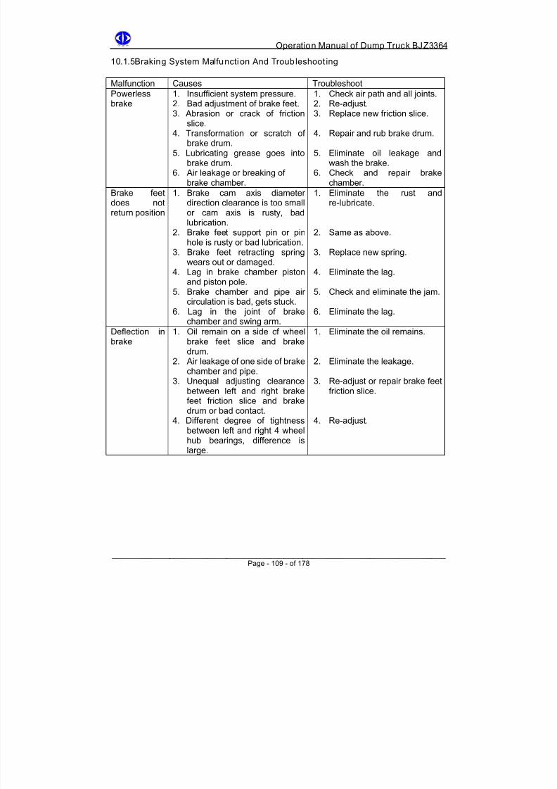
8/18/2019 d20 Bjz3364 Op Manual
http://slidepdf.com/reader/full/d20-bjz3364-op-manual 119/188
Operation Manual of Dump Truck BJZ3364
10.1.5Braking System Malfunction And Troubleshoot ing
Malfunction Causes Troubleshoot
Powerless
brake
1. Insufficient system pressure.
2. Bad adjustment of brake feet.3. Abrasion or crack of frictionslice.
4. Transformation or scratch ofbrake drum.
5. Lubricating grease goes intobrake drum.
6. Air leakage or breaking ofbrake chamber.
1. Check air path and all joints.
2. Re-adjust.3. Replace new friction slice.
4. Repair and rub brake drum.
5. Eliminate oil leakage andwash the brake.
6. Check and repair brakechamber.
Brake feetdoes not
return position
1. Brake cam axis diameterdirection clearance is too small
or cam axis is rusty, badlubrication.
2. Brake feet support pin or pinhole is rusty or bad lubrication.
3. Brake feet retracting springwears out or damaged.
4. Lag in brake chamber pistonand piston pole.
5. Brake chamber and pipe aircirculation is bad, gets stuck.
6. Lag in the joint of brake
chamber and swing arm.
1. Eliminate the rust andre-lubricate.
2. Same as above.
3. Replace new spring.
4. Eliminate the lag.
5. Check and eliminate the jam.
6. Eliminate the lag.
Deflection inbrake
1. Oil remain on a side of wheelbrake feet slice and brakedrum.
2. Air leakage of one side of brakechamber and pipe.
3. Unequal adjusting clearancebetween left and right brakefeet friction slice and brakedrum or bad contact.
4. Different degree of tightnessbetween left and right 4 wheelhub bearings, difference islarge.
1. Eliminate the oil remains.
2. Eliminate the leakage.
3. Re-adjust or repair brake feetfriction slice.
4. Re-adjust.
______________________________________________________________________ Page - 109 - of 178

8/18/2019 d20 Bjz3364 Op Manual
http://slidepdf.com/reader/full/d20-bjz3364-op-manual 120/188
Operation Manual of Dump Truck BJZ3364
10.2 Air Compressor
10.2.1Structure
Figure 58 - (AWC-10) Cummins Air Compressor (Single Cylinder)
1 Cooling fluid 4 Air entrance
2 Unload valve 5 Air entering valve
3 Air adjusting device tie-in 6 Air discharge valve
10.2.2Working Principle
Ai r entering
When piston moves downwards, partial vacuum appears in air cylinder, air is sucked into
air compressor through engine air entering branch pipe or air compressor’s air filter.
Difference between pressures in air cylinder and atmosphere makes air entering valve
move downwards and leave the valve seat, allow the air go into air cylinder through air
entrance. When piston reaches its lower stopping point in the stroke, pressure of spring is
sufficient to overcome relatively small pressure difference and make air entering valve
sustain valve seat, as shown in Fig 5-36 and 5-37.
Compression
When piston moves upwards, air pressure in the air cylinder increases, and forces air
discharging valve leave the valve seat. After that the piston continues moving upwards,
compressed air goes into air reservoir through air discharging valve. When piston moves
downwards, air discharging valve closes, air entering valve opens (except for when
unloading).
______________________________________________________________________ Page - 110 - of 178
8/18/2019 d20 Bjz3364 Op Manual
http://slidepdf.com/reader/full/d20-bjz3364-op-manual 121/188
Operation Manual of Dump Truck BJZ3364
Unloading
When air reservoir’s pressure is under some scheduled pressure, air pressure goes into
unloading machine cap’s upper part through a pressure adjusting device. This pressure
forces unloading cap downwards and keep air entering valve open (when no pump air
circulation).
10.2.3 Maintenance Of Air Compressor
1. When air compressor is working normally, very few machining oil goes into the
compressed air. If large amount of machining oil is often discharged from
double-entry brake distribution valve’s dirt discharging valve, it means the piston
ring may be broken or wrong assembly of ring gate uncork. Repair accordingly.
2. Check if it is smooth in air compressor’s oil pipe and water pipe, if it is tight in air
discharging pipe’s tie-in.
3. Observe if the engine is too hot after it starts, if there is knocking sound in air
cylinder’s piston and piston pin, if there is abnormal noise, find out the cause and
repair.
4. After every 1000-1500 traveling, disassemble the air compressor’s cylinder cover
and wash it carefully. Check the coordination condition of air entering valve’s
pistons, if there is serious abrasion must replace them.
______________________________________________________________________ Page - 111 - of 178

8/18/2019 d20 Bjz3364 Op Manual
http://slidepdf.com/reader/full/d20-bjz3364-op-manual 122/188
Operation Manual of Dump Truck BJZ3364
10.2.4 Air Compressor Malfunction Analysis And Troubleshooting
Malfunction Cause Troubleshoot
Insufficient
pressure, lowefficiency
1. Filter shared with engine is
too dirty and gets stuck.2. Abrasion or scratch of airentering valve, bad sealingcondition.
3. Clearance between pistonand air cylinder wall is toolarge or serious abrasion ofpiston ring.
4. Bad seal in air cylinder coverand air cylinder body.
5. Air leakage in airdischarging tie-in and jointpipe.
1. Use water with washing power
to wash and dry.2. Open cylinder cover, cleancarefully, smoothen the parts ofabrasion, if too serious thereplace.
3. Clean the dirt and smoothen thecylinder body.
4. Replace with new parts.
5. Disassemble from aircompressor and do welding orreplacement with new parts.
Oil jump in aircompressor
1. Air ring and oil ring gates areon the same line.
2. Serious abrasion of pistonring, scratch of cylinder bodyor ring lost.
3. Filter gets stuck or
machining oil return oil pipegets stuck. Machining oil issucked upwards, curve axistank oil level is too high.
1. Check and change gateposition.
2. Clean and check the openingclearance of piston ring incylinder, and transformation ofcylinder body, replace with newparts.
3. Disassemble, clean, penetrate
through.
Abnormalnoise in aircompressor
1. Serious abrasion in aircompressor each movingpart, coordinating clearancetoo large.
2. Fasten bolt or clearancebetween air compressor andengine axis joint device toolarge.
1. Replace if abrasion is tooserious.
2. Fasten the joint bolt or check joint axis device’s coordinatingclearance.
Abnormalworking ofunloadingvalve
1. Unloading valve springbroken or transformed.
2. Unloading valve gets stuckor inflexible.
3. Air leakage in sealing ringand pipe.
1. Replace.
2. Smoothen or replace new valvebody.
3. Replace the sealing gasket andpipe.
______________________________________________________________________ Page - 112 - of 178
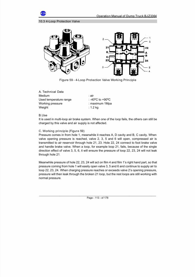
8/18/2019 d20 Bjz3364 Op Manual
http://slidepdf.com/reader/full/d20-bjz3364-op-manual 123/188
Operation Manual of Dump Truck BJZ3364
10.3 4-Loop Protection Valve
Figure 59 - 4-Loop Protection Valve Working Principle
A. Technical Data
Medium : air
Used temperature range : -40ºC to +90ºC
Working pressure : maximum 1Mpa
Weight : 1.2 kg
B.Use
It is used in multi-loop air brake system. When one of the loop fails, the others can still be
charged by this valve and air supply is not affected.
C. Working princip le (Figure 59)
Pressure comes in from hole 1, meanwhile it reaches A, D cavity and B, C cavity. When
valve opening pressure is reached, valve 2, 3, 5 and 6 will open, compressed air is
transmitted to air reservoir through hole 21, 23. Hole 22, 24 connect to foot brake valve
and handle brake valve. When a loop, for example loop 21, fails, because of the single
direction effect of valve 3, 5, 6, it will ensure the pressure of loop 22, 23, 24 will not leak
through hole 21.
Meanwhile pressure of hole 22, 23, 24 will act on film 4 and film 1’s right hand part, so that
pressure coming from hole 1 will easily open valve 3, 5 and 6 and continue to supply air to
loop 22, 23, 24. When charging pressure reaches or exceeds valve 2’s opening pressure,
pressure will then leak through the broken 21 loop, but the rest loops are still working with
normal pressure.
______________________________________________________________________ Page - 113 - of 178
8/18/2019 d20 Bjz3364 Op Manual
http://slidepdf.com/reader/full/d20-bjz3364-op-manual 124/188
Operation Manual of Dump Truck BJZ3364
10.4 Cartwheel Brake Chamber
A.Technical Data
Piston diameter : 150mm
Piston journey : 74mmWorking pressure : 750 kpa
B. Use
Wheel break is a device which converts air pressure to pushing brake feet and produce
brake force. The technique parameters and structures of front the rear wheel brake
chambers are totally different. Front wheel is piston type and rear wheel is working brake
together with handle brake, it is a combination of piston and film.
C.Working Principle
This chamber is a piston type. When braking, compressed air goes into this chamber
through end side tie-in, and pushed piston (4) into its motion, meanwhile moves swing arm
and make camshaft rotate, opens up brake feet and produce braking effect.
When braking is released, air in the cylinder is discharged into the atmosphere through
foot brake valve. Position returning spring (6) will push the piston back to its original
position and ready for the next brake. See Figure 60.
10.4.1 Assembly Of Front Brake Chamber
1. Before assembly, all the parts should be cleaned, there should not be any dust, crumbsor burrs. No scratch should be found on the working surface.
2. Fasten all the firmware, apply a little seal glue on pipe tie-in. Run the sealing test after
assembly.
3. When assembling piston and sealing ring, apply some lubricant lithium MoS2 grease
or industrial Vaseline on the working surface.
4. Assemble the piston assembly’s each part of (17)(15)(14)(13)(16)(4)(6)(7) together.
Be ware that some lubricant lithium MoS2 grease should be applied onto piston pole (5)
and spring seat (13) working surface. The position of dustproof cover (4) must be
correct.
5. Apply small amount of grease on air cylinder (15) working surface. When assembling
piston assembly and air cylinder cover (12), use spring seat (13) to planish the
dustproof cover (4). Screw down four fixed bolts (3) covered in spring gasket (2).
Screw down torque is 32 Nm.
6. Be ware of the sealing of screw down tie-in (18). Finally get into pin axis (8) and put on
gasket ring and opening pin (9).
7. After assembly, 50 kpa of compressed air should be filled into brake chamber. At this
moment the piston should be above to push out rapidly with 74mm journey, and return
to its original position under the effect of position returning spring after unloading.
______________________________________________________________________ Page - 114 - of 178

8/18/2019 d20 Bjz3364 Op Manual
http://slidepdf.com/reader/full/d20-bjz3364-op-manual 125/188
Operation Manual of Dump Truck BJZ3364
Figure 60 - Wheel Front Chamber
1 Air entering tie-in 5 Piston pole
2 Air cylinder body 6 Position returning spring
3 Sealing ring 7 Dustproof cover
4 Piston 8 Joint fork
Figure 61 - Front Brake Chamber Parts
______________________________________________________________________ Page - 115 - of 178
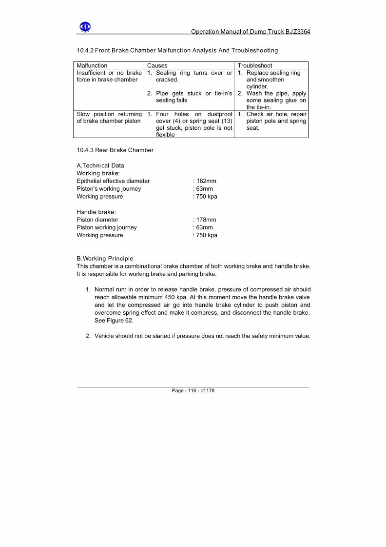
8/18/2019 d20 Bjz3364 Op Manual
http://slidepdf.com/reader/full/d20-bjz3364-op-manual 126/188
Operation Manual of Dump Truck BJZ3364
10.4.2 Front Brake Chamber Malfunct ion Analysis And Troubleshooting
Malfunction Causes Troubleshoot
Insufficient or no brakeforce in brake chamber
1. Sealing ring turns over orcracked.
2. Pipe gets stuck or tie-in’ssealing fails
1. Replace sealing ringand smoothencylinder.
2. Wash the pipe, applysome sealing glue onthe tie-in.
Slow position returningof brake chamber piston
1. Four holes on dustproofcover (4) or spring seat (13)get stuck, piston pole is notflexible
1. Check air hole, repairpiston pole and springseat.
10.4.3 Rear Brake Chamber
A.Technical Data
Working brake:
Epithelial effective diameter : 162mm
Piston’s working journey : 63mm
Working pressure : 750 kpa
Handle brake:
Piston diameter : 178mmPiston working journey : 63mm
Working pressure : 750 kpa
B.Working Principle
This chamber is a combinational brake chamber of both working brake and handle brake.
It is responsible for working brake and parking brake.
1. Normal run: in order to release handle brake, pressure of compressed air should
reach allowable minimum 450 kpa. At this moment move the handle brake valve
and let the compressed air go into handle brake cylinder to push piston and
overcome spring effect and make it compress, and disconnect the handle brake.
See Figure 62.
2. Vehicle should not be started if pressure does not reach the safety minimum value.
______________________________________________________________________ Page - 116 - of 178

8/18/2019 d20 Bjz3364 Op Manual
http://slidepdf.com/reader/full/d20-bjz3364-op-manual 127/188

8/18/2019 d20 Bjz3364 Op Manual
http://slidepdf.com/reader/full/d20-bjz3364-op-manual 128/188
Operation Manual of Dump Truck BJZ3364
Handle Brake Position
Fast Release Valve Air Circulating Handle Brake
Figure 64 - Chamber In Parking Brake
Released Handle BrakeTravel Position
Figure 65 - Chamber In Released Brake By Manual
______________________________________________________________________ Page - 118 - of 178

8/18/2019 d20 Bjz3364 Op Manual
http://slidepdf.com/reader/full/d20-bjz3364-op-manual 129/188
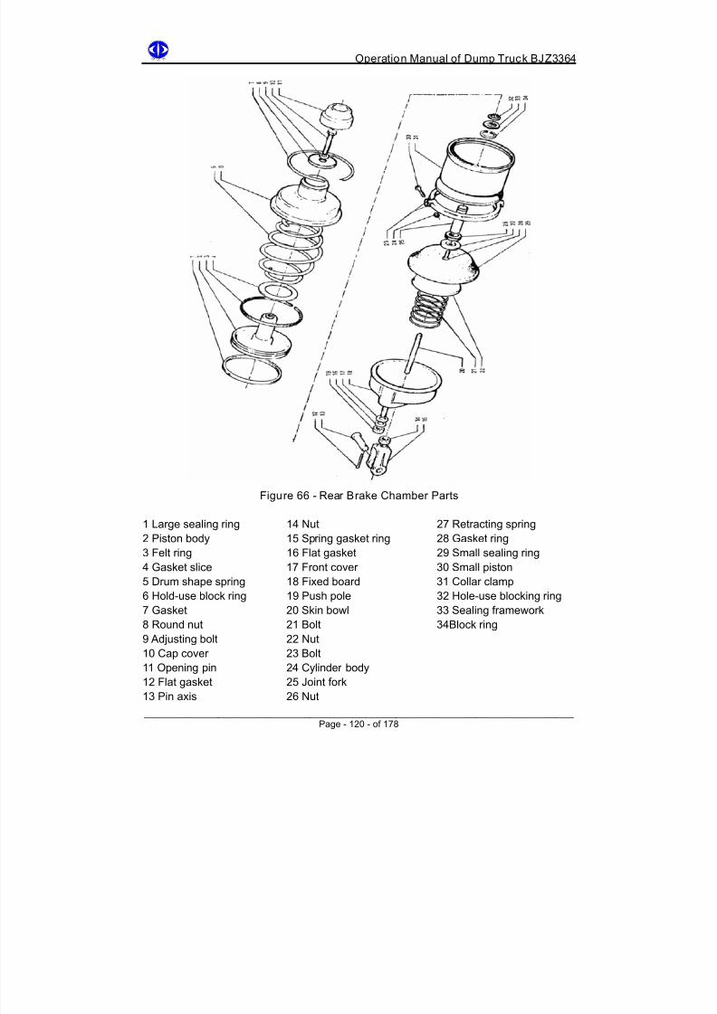
8/18/2019 d20 Bjz3364 Op Manual
http://slidepdf.com/reader/full/d20-bjz3364-op-manual 130/188
Operation Manual of Dump Truck BJZ3364
Figure 66 - Rear Brake Chamber Parts
1 Large sealing ring 14 Nut 27 Retracting spring
2 Piston body 15 Spring gasket ring 28 Gasket ring
3 Felt ring 16 Flat gasket 29 Small sealing ring
4 Gasket slice 17 Front cover 30 Small piston
5 Drum shape spring 18 Fixed board 31 Collar clamp
6 Hold-use block ring 19 Push pole 32 Hole-use blocking ring
7 Gasket 20 Skin bowl 33 Sealing framework
8 Round nut 21 Bolt 34Block ring
9 Adjusting bolt 22 Nut
10 Cap cover 23 Bolt
11 Opening pin 24 Cylinder body
12 Flat gasket 25 Joint fork13 Pin axis 26 Nut
______________________________________________________________________ Page - 120 - of 178

8/18/2019 d20 Bjz3364 Op Manual
http://slidepdf.com/reader/full/d20-bjz3364-op-manual 131/188
Operation Manual of Dump Truck BJZ3364
12. Put the skin bowl (21) in between handle brake cylinder and working brake
chamber front cover. Install the collar clamp (32) and screw down the fixed bolt (24).
When screwing down, use a wooden hammer to knock the collar clamp (32)
surrounding lightly to make it into the right position. Then screw down two fixedbolts (24), the torque is 49 Nm.
13. Under a 750 kpa pressure, charge the brake chamber. Check the sealing condition
of collar clamp (32).
14. After the whole assembly, install the joint fork (26) and nut (27) for the last check.
15. Testing requirements for whole vehicle check: when filling 50 kpa compressed air
into the working brake chamber, piston should be quickly pushed with 62mm
journey. After discharging the air it should immediately return its position. When
filling 450 kpa compressed air into handle brake cylinder, handle brake should be
immediately released.
16. Adjustment of handle brake should be done during assembly. Fill the compressed
air into handle brake chamber, turning the brake releasing bolt (10) and push the
front push pole (20) all the way till the end. Finally cover the brake chamber cap
cover (11).
Figure 67 - Rear Brake Assembly
______________________________________________________________________ Page - 121 - of 178

8/18/2019 d20 Bjz3364 Op Manual
http://slidepdf.com/reader/full/d20-bjz3364-op-manual 132/188
Operation Manual of Dump Truck BJZ3364
10.4.5 Malfunction Analysis And Troubleshooting
Malfunction Causes Troubleshoot
Working brake is
always in workingstate
1. Air leakage in cylinder’s
sealing parts and smallpiston.2. Air leakage in cylinder rear
part’a adjusting bolt.
1. Check and replace the
big and small pistonsealing ring.2. Check and replace the
small piston’s O shapering.
Air leakage inworking brakechamber
1. Looseness of collar clamp,uneven tightness of thesurrounding, air leakagefrom collar clamp.
2. Crack in skin film.
1. Re-screw down collarclamp bolt with torque29Nm.
2. Replace with new skinbowl.
Handle brake failsInsufficient force
1. Damage or transformationof drum shape spring.
2. Jam or incomplete aircirculation of air pipe
1. Replace with new drumshape spring.
2. Check and wash thepipe.
______________________________________________________________________ Page - 122 - of 178

8/18/2019 d20 Bjz3364 Op Manual
http://slidepdf.com/reader/full/d20-bjz3364-op-manual 133/188
Operation Manual of Dump Truck BJZ3364
10.5 Cartwheel Arrester
A.Technical Data
Brake drum diameter : 462mm
Friction slice width : 180mm
Friction area : 1584mm2
Friction slice dimension (length×width×height) : 220×180×15mm
Friciont slice’s frictional index
(with temperature 350oC) : 0.35-0.4
B. Use
Wheel arrester is used to directly produce power torque, and stop wheel rotation and
reduce the speed or stop of vehicle. The parameter and structure of front and rear wheel
arrester are basically the same. They are both simple and non-balance inner expanding
drum type arrester.
C. Working principle
This vehicle uses simple non-balance inner expanding drum type arrester. See Fig 10-5-1.
Two brake feet (3) are supported on the support pin (2). Brake feet (3) is driven by wheel
brake chamber light swing arm (11) and camshaft (6). Brake feet is in contact with brake
cam through rolling wheel (9) to reduce the frictional loss of cam.
When braking during vehicle forward movement, the compressed air opens the two brakefeet (3) through swing arm (11) pushed by brake chamber piston and rotating cam (6), and
press hard on the brake drum (1). It produces a frictional torque to the rotating brake drum
and stops the rotation of wheel so the vehicle starts to slow down.
Figure 68
______________________________________________________________________ Page - 123 - of 178

8/18/2019 d20 Bjz3364 Op Manual
http://slidepdf.com/reader/full/d20-bjz3364-op-manual 134/188
Operation Manual of Dump Truck BJZ3364
1 Brake drum 7 Adjusting spline cover
2 Support pin 8 Adjusting bolt
3 Brake feet 9 Idler wheel
4 Retracting spring 10 Nut
5 Retracting spring pin 11 Adjusting arm6 Camshaft
The clearance between brake feet friction slice (3) and brake drum (1) is adjusted by
triangle spline cover (7). In order to make the clearance at idler wheel between brake drum
and friction slice to be 0.65mm, and 0.35mmat support pin position, we can rotate the
adjusting bolt (8). If the screw thread of this bolt is to the greatest extent, then get off the
adjusting spline cover (7), rotate by one tooth then re-adjust.
Figure 69 - Front Arrester
______________________________________________________________________ Page - 124 - of 178

8/18/2019 d20 Bjz3364 Op Manual
http://slidepdf.com/reader/full/d20-bjz3364-op-manual 135/188
Operation Manual of Dump Truck BJZ3364
10.5.1Assembly Of Front Wheel Arrester
1. Wash all the parts before assembly. No burrs, no flying edge, especially no scratch
or oil dirt on the friction slice and brake drum’s working surface.
2. Carry out the drill of friction slice (1) and brake feet only on the specific machine.When use rivet (3) for riveting, it should be done from one end to the other, or from
middle to the two ends, so that there will not be any clearance. When riveting, its
rivet head should touch the fiction slick hole bottom part closely, and lower than half
of the thickness of friction slice. In order ensure good contact between friction slice
and brake drum, carry out the outer circle grinding on specific machine. See Figure
70.
Figure 70
3. After riveting the friction slice and brake feet, the maximum partial clearance should
not exceed 0.25mm or use the knocking sound to check the riveting condition.
4. After pressing the lining (4) into feet hole, use support pin (7) to check the
coordinating condition. If there is transformation, use ream knife’s ream hole and
install idler wheel axis (5) and idler wheel (6).
5. Wash two support pin (7), apply small amount of grease into front knuckle, at the
same time cover the camshaft (8) with felt ring (9) and install into knuckle. Beware
of the left and right different of camshaft, the direction of cam must follow the
moving direction of wheel.
6. Install the retracting spring (10) and two retracting spring pin (11) on two feet (2),
and then install the two feet together onto front knuckle. Apply some grease on the
support pin and cam surface when assembling, finally install the gasket ring (12)
and axis-use collar (13).
7. Insert the adjusting spline cover (7), install the adjusting bolt (15) and nut (16) into
brake arm (17), then together put into camshaft spline. Beware of the relative
position of brake arm upper end and brake chamber support. Finally install the
axis-use block ring (18).
8. Install the brake drum (19) on front wheel hub, screw down 8 fixed bolts (22). Drip
some loose proof potion when screw down. Beware of the symmetry whenscrewing, the screw down torque is 314 Nm.
______________________________________________________________________ Page - 125 - of 178

8/18/2019 d20 Bjz3364 Op Manual
http://slidepdf.com/reader/full/d20-bjz3364-op-manual 136/188
Operation Manual of Dump Truck BJZ3364
9. For brake feet assembly, use the specific machine to check the clearance between
friction slice and brake drum, it should be 0.65mm at cam and 0.35mm at support
pin. The upper and lower feet should be consistent.
10. Finally install two oil nozzles (23) on the two support pin (7) and apply some
grease.
10.5.2Assembly Of Rear Wheel Arrester
1. The riveting of rear wheel arrester friction slice and brake feet, lining and idler
wheel’s assembly are basically the same as front wheel arrester. We will not repeat
here.
2. Install the camshaft seat (9) on rear axis, get into bolt (10) gasket ring (11) and
finally screw down the bolt, screw down torque is 44 Nm. Apply some loose proof
potion on this bolt.
Figure 71 - Rear Wheel Arrester KD
3. Press the two camshaft cover (7) (8) into camshaft seat (9) two ends, do not
scratch the working surface of cover when assembly, apply some grease.
4. Insert the spline cover (18), install adjusting bolt (19) and nut (20) into brake arm
(21). Then together put them on camshaft spline. Beware of proper position of
brake arm upper end and brake chamber support. Finally install the axis-use blockring (22) and meanwhile carry out the check just as the arrester.
5. Finally install the rear brake drum (23) on rear wheel hub, put on stop gasket ring
(24), screw down 8 fixed bolts (25). Beware of the symmetry when screwing, screw
down torque is 275-314 Nm, move the stop gasket slice and install it on the rear
axis, at the same time install the oil nuzzle (26), apply some grease.
10.5.3Adjustment Of Arrester
______________________________________________________________________
There is abrasion of arrester’s friction slice along with the vehicle operation, so must
adjust regularly. When the thickness of friction slice is smaller than 9mm (minimum limit),replace it.
Page - 126 - of 178

8/18/2019 d20 Bjz3364 Op Manual
http://slidepdf.com/reader/full/d20-bjz3364-op-manual 137/188

8/18/2019 d20 Bjz3364 Op Manual
http://slidepdf.com/reader/full/d20-bjz3364-op-manual 138/188
Operation Manual of Dump Truck BJZ3364
10.6 Air Reservoir
A. Technique Data
Model : three unattached air reservoir
Working capacity:
Front air reservoir : 55 L
Rear air reservoir : 60 L
Regenerating air reservoir : 5 L
Working pressure : 750 Kpa
B. Use
It is used for reserving some compressed air to backup the brake system and other
assisting devices. It can help stabilize pressure, lower the temperature and clean the oil
dirt.
C. Structure And Working Principle
The air reservoirs are two in parallel. See Figure 72. Used working pressure is 750 Kpa,
their capacity is about 60 L. A block board is welded in the upper air reservoir (1), divide
the reservoir into 5L and 55L. Hence the air reservoir are divided into three separate parts:
regenerating air reservoir (1), front brake chamber air reservoir (4) and rear brake
chamber air reservoir (5).Water discharging valve (6) is installed on the bottom of each air reservoir. It is used for
discharging the oil water. When using, just press its valve pole.
Figure 72 - Air Reservoir
1 Regenerating air reservoir 4 Front air reservoir
2 Middle block board 5 Rear air reservoir
3 Tie-in seat 6 Water discharging valve
______________________________________________________________________ Page - 128 - of 178

8/18/2019 d20 Bjz3364 Op Manual
http://slidepdf.com/reader/full/d20-bjz3364-op-manual 139/188
Operation Manual of Dump Truck BJZ3364
10.6.1 Main Malfunction And Maintenance
Usually there is no malfunction of air reservoir. The possible causes of malfunction may be
due to damage in retracting spring or rubber seal ring gets old and transformed,disassemble and check, replace the spring and seal ring. See Figure 73.
In order to reduce the deposit water and rust of water discharging valve, need to discharge
water regularly.
Figure 73 - Air Reservoir Water Discharge Valve
10.7 Hand Brake Valve
A.Technique Parameter Model : two position three connecting valve
Valve’s venthole diameter : 8mm
Working pressure : 750 kpa
B.Use
Handle brake device is vehicle’s parking brake device. This vehicle functions directly onto
the rear axis wheel. It is controlled by rear axis double cavity brake chamber. Here the
function of compressed air is to keep the handle brake device in brake releasing state.
Compressed air releasing makes it easy for handle brake device to produce brake effect.
Use instrument panel’s hand brake valve to control the hand brake device.
Handle brake control valve is usually closed two position three connecting valve. See
Figure 74. This valve is installed on the driver cab’s instrument panel. Handle has only two
brake position, right is driving position.
______________________________________________________________________ Page - 129 - of 178

8/18/2019 d20 Bjz3364 Op Manual
http://slidepdf.com/reader/full/d20-bjz3364-op-manual 140/188
Operation Manual of Dump Truck BJZ3364
Figure 74 - Handle Brake Valve Principle
1 Air reservoir 3 Quick release valve
2 Handle brake valve 4 Rear brake sub-pump
C. Working Principle
The compressed air from rear air reservoir (1) is connected to handle brake control valve’s
air entrance through pipe. The compressed air goes into air exit through seal ring A’s
middle hole, and passes through pipe and quick release valve (3) to rear brake chamber(4). Valve B closes the pathway between air exit and atmosphere, makes the parking
vehicle in the releasing state.
In reverse, when handle pushes to the left, valve B moves downwards, seal the seal ring
A’s middle hole, closes the pathway between air entrance and air exit. At the same time it
opens the pathway between air exit and atmosphere, so the compressed air form rear
brake pipe will be released to the outside through large air hole, the compressed air from
rear brake chamber is discharged into the atmosphere through quick release valve (3).
Parking brake moves the brake chamber’s puller under the effect of spring, and carries out
the vehicle brake through arrester.
On the other hand, self dump device should also be controlled by this kind of valve. The
control manner is the same as above. When the compressed air passes through this valve,
lower down the carriage. The opposite procedure is for lifting.
______________________________________________________________________ Page - 130 - of 178

8/18/2019 d20 Bjz3364 Op Manual
http://slidepdf.com/reader/full/d20-bjz3364-op-manual 141/188
Operation Manual of Dump Truck BJZ3364
10.7.1 Malfunct ion Analysis And Troubleshoot
Fig Causes Troubleshoot
Handleposition
Airflowpathway
1. When handle in thisposition, if valve B’s sealring and seat’s sealingcondition is bad or valvepole is not completely backto its position, and air leaksfrom large air hole,insufficient pressurecauses incomplete parkingbrake releasing
1. Repair this valve’sseal ring and valvepole
2. Check and repairvalve seat
Handle
position
Airflowpathway
1. When handle is in a
position shown in thefigure, it is a parkingposition (Fig 10-7-1), ifvalve B and seal ring A’ssealing condition is bad,compressed air will enterthe brake chamber from airentrance and through airexit, thus the parking brakedoes not work
1. Check this valve’s
seal ring A, iftransformed ordamaged mustreplace with newparts.
______________________________________________________________________ Page - 131 - of 178

8/18/2019 d20 Bjz3364 Op Manual
http://slidepdf.com/reader/full/d20-bjz3364-op-manual 142/188

8/18/2019 d20 Bjz3364 Op Manual
http://slidepdf.com/reader/full/d20-bjz3364-op-manual 143/188
Operation Manual of Dump Truck BJZ3364
10.9 Foot Brake Valve
A.Technique Data
Medium : air
Temperature range for use : -40ºC +80ºC
Working pressure : maximum 1 Mpa
Relative over pressure between #1 loop and #2 loop : ∆P=30 Kpa10
20
+
−
B. Use
To fulfill flexible control in double loop main brake system’s brake process and releasing
process.
C. Working Principle
Control the mandril K and mandril seat a, for the action of brake valve through pedal
control device.
When braking, mandril seat a moves downwards by the pushing from rubber spring b.
Close air discharging gate d, open air entering gate j. Compressed air from gate 11
reaches cavity A. Then from gate 21 output to brake pipe I. Meanwhile airflow reaches
cavity B through hole D and functions on piston f for its downward movement. Close air
discharging gate h, open air entering gate g, the compressed air form gate 12 reaches
cavity c, and from gate 22 outputs to brake pipe II.
When braking is released, the pressure from gate 21, 22 is discharged to atmosphere
separately through air discharging gate d and h and gate 3.
When #1 loop fails, piston f is pushed downwards through valve assembly e. Close air
discharging gate h, open air entering gate g, to make #2 loop works normally. When #2loop fails, it does not affect the working of #1 loop.
______________________________________________________________________ Page - 133 - of 178
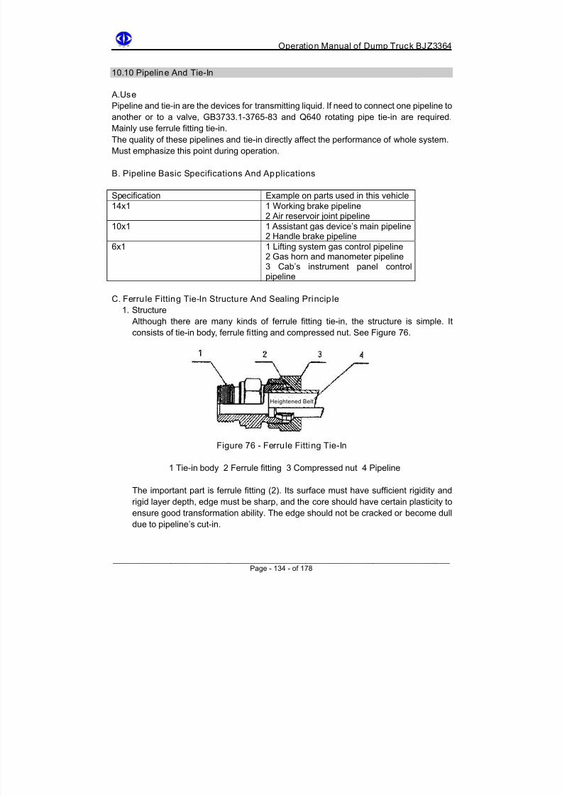
8/18/2019 d20 Bjz3364 Op Manual
http://slidepdf.com/reader/full/d20-bjz3364-op-manual 144/188
Operation Manual of Dump Truck BJZ3364
10.10 Pipeline And Tie-In
A.Use
Pipeline and tie-in are the devices for transmitting liquid. If need to connect one pipeline toanother or to a valve, GB3733.1-3765-83 and Q640 rotating pipe tie-in are required.
Mainly use ferrule fitting tie-in.
The quality of these pipelines and tie-in directly affect the performance of whole system.
Must emphasize this point during operation.
B. Pipeline Basic Specifications And Applications
Specification Example on parts used in this vehicle
14x1 1 Working brake pipeline
2 Air reservoir joint pipeline10x1 1 Assistant gas device’s main pipeline
2 Handle brake pipeline
6x1 1 Lifting system gas control pipeline2 Gas horn and manometer pipeline3 Cab’s instrument panel controlpipeline
C. Ferru le Fitting Tie-In Structure And Sealing Princip le
1. Structure
Although there are many kinds of ferrule fitting tie-in, the structure is simple. Itconsists of tie-in body, ferrule fitting and compressed nut. See Figure 76.
Heightened Belt
Figure 76 - Ferrule Fitting Tie-In
1 Tie-in body 2 Ferrule fitting 3 Compressed nut 4 Pipeline
The important part is ferrule fitting (2). Its surface must have sufficient rigidity and
rigid layer depth, edge must be sharp, and the core should have certain plasticity to
ensure good transformation ability. The edge should not be cracked or become dull
due to pipeline’s cut-in.
______________________________________________________________________ Page - 134 - of 178

8/18/2019 d20 Bjz3364 Op Manual
http://slidepdf.com/reader/full/d20-bjz3364-op-manual 145/188
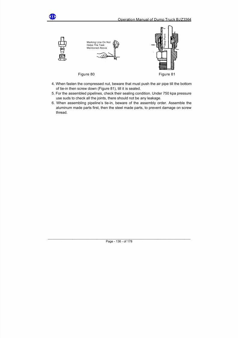
8/18/2019 d20 Bjz3364 Op Manual
http://slidepdf.com/reader/full/d20-bjz3364-op-manual 146/188
Operation Manual of Dump Truck BJZ3364
S
t o p P o i n t
Marking Line On Nut
Helps The TaskMentioned Above
Figure 80 Figure 81
4. When fasten the compressed nut, beware that must push the air pipe till the bottom
of tie-in then screw down (Figure 81), till it is sealed.
5. For the assembled pipelines, check their sealing condition. Under 750 kpa pressure
use suds to check all the joints, there should not be any leakage.
6. When assembling pipeline’s tie-in, beware of the assembly order. Assemble the
aluminum made parts first, then the steel made parts, to prevent damage on screw
thread.
______________________________________________________________________ Page - 136 - of 178

8/18/2019 d20 Bjz3364 Op Manual
http://slidepdf.com/reader/full/d20-bjz3364-op-manual 147/188

8/18/2019 d20 Bjz3364 Op Manual
http://slidepdf.com/reader/full/d20-bjz3364-op-manual 148/188
Operation Manual of Dump Truck BJZ3364
Figure 82
1 Front thrust pole 6 Front rubber auxiliary spring
2 Front spring front suspend ear 7 Tube shock absorber
3 Pin 8 Front axis
4 Front main spring 9 Vehicle frame
5 Front spring pressing board 10 Front spring rear suspend ear
11.2 Rear Suspension
See Figure 83. Rear suspension consists of main spring, auxiliary and thrust pole powertransmission mechanism.
1. Rear steel board spring main spring consists of 2 main slices, 6 auxiliary and 1
compressed slice.
2. Auxiliary spring consists of double point symmetrical rubber block.
3. When vehicle parks with full load, rear auxiliary spring has to bear with 40% load of
rear axis. If there is impact during traveling, it has to bear with 60% load, about 16
tons. So once the rear auxiliary spring is broken, must replace with new one in time,
otherwise rear steel board spring main spring has to bear with the whole load. Main
spring will so crack. Must not ignore this point.
4. Thrust pole is shown as part (2) in Figure 83. It is power transmission mechanism. It
transmits the rear axis driving power to vehicle frame. It can also control portrait
location and balance brake torque.
______________________________________________________________________ Page - 138 - of 178

8/18/2019 d20 Bjz3364 Op Manual
http://slidepdf.com/reader/full/d20-bjz3364-op-manual 149/188
Operation Manual of Dump Truck BJZ3364
Vehicle Frame
Rear Axl e Casing
Figure 83
1 Front support 4 Main spring pressing board
2 Thrust pole 5 Rubber auxiliary spring
3 Main spring 6 Rear support
11.3 Assembly / Disassembly Notice
1. When steel board spring bears with loads and transforms, relative sliding happens in
between the slices to absorb the shock. Clean the slices before assembly, applygraphite grease and list it as a maintenance item, for normal use and lifespan
lengthening.
During the use do not only care about replacing the broken slice, also wash and apply
grease, otherwise it will causes steel board spring to self-friction, increases the
frictional force between the slices and reduce the capability of shock absorption. The
wheel will have to bear with more impact and pass to the vehicle frame, and this will
affect the lifespan of the vehicle. When assembling/disassembling the steel board
spring, must not use steel made hammer to knock.
2. Rubber auxiliary spring: it is a substantial rubber part and is used to protect the main
spring. It has small initial rigidity and larger terminal rigidity, so that when road condition
is bad, it will effectively protect the main spring.
______________________________________________________________________ Page - 139 - of 178
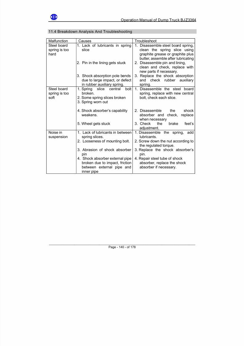
8/18/2019 d20 Bjz3364 Op Manual
http://slidepdf.com/reader/full/d20-bjz3364-op-manual 150/188
Operation Manual of Dump Truck BJZ3364
11.4 Breakdown Analysis And Troubleshooting
Malfunction Causes Troubleshoot
Steel boardspring is toohard
1. Lack of lubricants in springslice
2. Pin in the lining gets stuck
3. Shock absorption pole bendsdue to large impact, or defectin rubber auxiliary spring.
1. Disassemble steel board spring,clean the spring slice usinggraphite grease or graphite plusbutter, assemble after lubricating
2. Disassemble pin and lining,clean and check, replace withnew parts if necessary.
3. Replace the shock absorptionand check rubber auxiliaryspring.
Steel board
spring is toosoft
1. Spring slice central bolt
broken.2. Some spring slices broken3. Spring worn out
4. Shock absorber’s capabilityweakens.
5. Wheel gets stuck
1. Disassemble the steel board
spring, replace with new centralbolt, check each slice.
2. Disassemble the shockabsorber and check, replacewhen necessary
3. Check the brake feet’sadjustment.
Noise insuspension
1. Lack of lubricants in betweenspring slices.
2. Looseness of mounting bolt.
3. Abrasion of shock absorberpin
4. Shock absorber external pipebroken due to impact, frictionbetween external pipe andinner pipe
1. Disassemble the spring, addlubricants.
2. Screw down the nut according tothe regulated torque.
3. Replace the shock absorber’spin.
4. Repair steel tube of shockabsorber, replace the shockabsorber if necessary.
______________________________________________________________________ Page - 140 - of 178

8/18/2019 d20 Bjz3364 Op Manual
http://slidepdf.com/reader/full/d20-bjz3364-op-manual 151/188

8/18/2019 d20 Bjz3364 Op Manual
http://slidepdf.com/reader/full/d20-bjz3364-op-manual 152/188

8/18/2019 d20 Bjz3364 Op Manual
http://slidepdf.com/reader/full/d20-bjz3364-op-manual 153/188
Operation Manual of Dump Truck BJZ3364
2. Prevent overload. The damage brought by overload is similar to that of by low pressure.
But for overload the stress is even larger, the tyre temperature is higher, so the wearing
is more serious.
3. Prevent contact with oil substances, especially do not park the vehicle at where themachining oil, gasoline and butter is, else the rubber will deteroprate or transform.
4. Beware of maintenance of traveling road surface. The quality of road surface will greatly
affect the tyre’s lifespan. The abrasion of tyre will increase if the road surface becomes
rougher. So do the maintenance and make sure the road surface is flat.
5. Carefully drive the vehicle. The endurance of tyre also depends on the driving skill to a
large extend. Incorrect or careless driving will dramatically reduce the tyre travel
journey. Sudden start, sudden brake, sudden turn or collision with obstacles should all
be prevented.
6. Beware of storage. When storing the tyre, prevent high temperature, direct sunshine or
getting wet, prevent contact with acid, alkali, salt, oil or any organic solvent. Prevent
drench or dunking into water. Storeroom’s temperature should be kept at -15ºC to
+30ºC, relative humidity should be around 50-80%. Must not put the tyre near to heat
radiation device.
12.5 Breakdown Analysis And Troubleshooting
Malfunction Causes Troubleshoot
Abrasion of two side tyreshoulder
Insufficient charge Charge according to therequirement
Abrasion in the middle oftyre
Over charge Charge according to therequirement
Abnormal abrasion onthe inner tyre
Insufficient wheel angleor front toe too large
Change wheel angleRe-adjust front toe
Abnormal abrasion onthe outer tyre Wheel angle too large orfront wheel expandsoutwards (anti-front toe)
Change wheel angleRe-adjust front to
______________________________________________________________________ Page - 143 - of 178

8/18/2019 d20 Bjz3364 Op Manual
http://slidepdf.com/reader/full/d20-bjz3364-op-manual 154/188
Operation Manual of Dump Truck BJZ3364
Chapter 13
Hydraulic Pressure Dump System
13.1 Technical Data
Rating working pressure : 8335 kpa
Lifting oil pump nominal flux : (1000rpm) 215L/min
Oilcan capacity : 95 L
Carriage lifting time (with full load) : not more than 20 seconds
Carriage lowering down time : not more than 20 seconds
Maximum working temperature : 10OºC
13.2 Function
Hydraulic dump mechanism can realize carriage dump by itself. Since this oilcan is a
single direction function can, the carriage is lowered down to its original position by its own
weight.
13.3 Assembly And Working Principle
Hydraulic dump mechanism is required to be convenient and flexible, safe and reliable,and can ensure carriage lifting, stop while lifting, descending, stop while descending and
lifting safety automatic limit position.
Hydraulic dump mechanism consists of oil pump, lifting cylinder, distribution valve, oil tank
and oil pipe. See Figure 85. Oil pump is driven by gear box power obtaining device to
produce hydraulic pressure oil with certain pressure and flux for lifting cylinder to use.
Lifting cylinder is connected to vehicle case. The pressure oil goes into lifting cylinder, and
lifting cylinder will produce push force sufficient to lift the carriage.
Distribution valve is controlled by pressure control. Distribution valve is a combinational
hydraulic pressure valve, it has the function of safe overflow protection, changing oil flow
direction, opening and closing oil path and preventing oil from lifting can flows reversely
into oil pump.
______________________________________________________________________ Page - 144 - of 178

8/18/2019 d20 Bjz3364 Op Manual
http://slidepdf.com/reader/full/d20-bjz3364-op-manual 155/188
Operation Manual of Dump Truck BJZ3364
Figure 85 - Hydraulic Dump Mechanism System
13.4 Lift Pump
13.4.1 Structure And Working Principle
Lifting system uses gear oil pump. Figure 86 shows a double connecting parallel gear oil
pump. Its structure is simple, double metal abrasion endurance gasket slice is installed on
gear end surface.
It has a long lifespan and not broken easily. So, even though this kind of oil pump’s gear
end surface clearance is irreversible, it can work steadily for a long time, and maintenance
and repair are also relatively convenient.
______________________________________________________________________ Page - 145 - of 178

8/18/2019 d20 Bjz3364 Op Manual
http://slidepdf.com/reader/full/d20-bjz3364-op-manual 156/188
Operation Manual of Dump Truck BJZ3364
Figure 86 - Lifting Oil Pump Section
1 Joint cover 8 Bearing
2 Oil seal 9 Pump shell
3 Pump shell 10 Axis
4 Sealing ring 11 Bolt
5 Pump shell 12 Oil seal
6 Gear 13 Main axis
7 Abrasion endurance gasket slice
Oil pump’s rating working pressure is 8335 kpa, the maximum working pressure is 9806kpa, nominal flux is193 L/min, practical flux is 173 L/min (oil pump rotation speed 900 rpm).
It is better to take about 800 rpm for oil pump rotation speed (oil pump nominal flux is
about 172 L/min, practical flux is 154 L/min, engine rotation speed is less than 1800 rpm).
When oil pump axis rotates, it rotate the driving gear on the pump axis, driven gear will
then rotate under the driving force of driving gear with the same rotation speed. As shown
in Figure 87, when gear rotates it will compress the hydraulic oil from oil pump oil suck
gate through gear teeth into hydraulic distribution valve and hydraulic pressure cylinder.
Oil Exit
Oil Suction
Figure 87 - Oil Pump Working Principle
______________________________________________________________________ Page - 146 - of 178

8/18/2019 d20 Bjz3364 Op Manual
http://slidepdf.com/reader/full/d20-bjz3364-op-manual 157/188
Operation Manual of Dump Truck BJZ3364
13.4.2 Assembly / Disassembly Notice And Technical Requirements
Figure 88 - Lifting Oil Pump Section
1. Do not damage oil pump and the sealing rings, especially do not put oil seal and rubber
sealing ring into gasoline or diesel oil for cleaning, otherwise the rubber will
metamorphose.
2. Do not injury the working surface and keep it clean.
3. Do not mix gear (9), (33) and abrasion reduction gasket slice (8). Separate them during
assembly/disassembly. If mistaken, axis-direction clearance will change. Must not
install the gasket slice in wrong direction.
4. Install the rollers fully. Do not skip any of them. Replace if roller gets seriously burnt.
5. Keep the gear end surface smooth. Use blade ruler to check, it is best if there is not light
penetration. Repair or replace if the abrasion is too serious.
6. Gear end surface abrasion reduce gasket slice is a main part to keep the capability of oil
pump, but it is also easily broken. If the abrasion of surface is too serious, replace it.
7. When assembling, especially repairing or after changing the parts, must check and
adjust the axis-direction clearance for assembly. It must not exceed 0.06mm, otherwise
it will increase the leakage, oil pump capability will not meet the requirement. But the
end surface clearance should not be small than 0.01mm, otherwise there will be lag
when operating.
______________________________________________________________________ Page - 147 - of 178
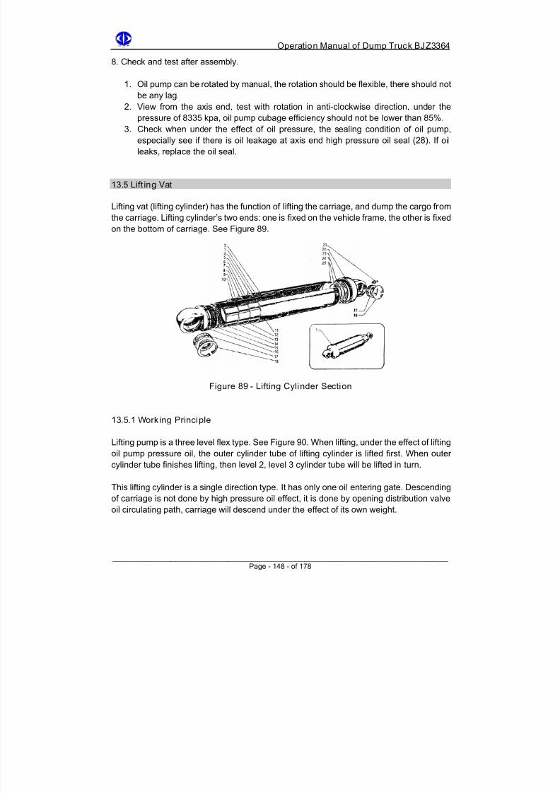
8/18/2019 d20 Bjz3364 Op Manual
http://slidepdf.com/reader/full/d20-bjz3364-op-manual 158/188
Operation Manual of Dump Truck BJZ3364
8. Check and test after assembly.
1. Oil pump can be rotated by manual, the rotation should be flexible, there should not
be any lag.
2. View from the axis end, test with rotation in anti-clockwise direction, under thepressure of 8335 kpa, oil pump cubage efficiency should not be lower than 85%.
3. Check when under the effect of oil pressure, the sealing condition of oil pump,
especially see if there is oil leakage at axis end high pressure oil seal (28). If oil
leaks, replace the oil seal.
13.5 Lift ing Vat
Lifting vat (lifting cylinder) has the function of lifting the carriage, and dump the cargo from
the carriage. Lifting cylinder’s two ends: one is fixed on the vehicle frame, the other is fixed
on the bottom of carriage. See Figure 89.
Figure 89 - Lifting Cylinder Section
13.5.1 Working Principle
Lifting pump is a three level flex type. See Figure 90. When lifting, under the effect of lifting
oil pump pressure oil, the outer cylinder tube of lifting cylinder is lifted first. When outer
cylinder tube finishes lifting, then level 2, level 3 cylinder tube will be lifted in turn.
This lifting cylinder is a single direction type. It has only one oil entering gate. Descending
of carriage is not done by high pressure oil effect, it is done by opening distribution valve
oil circulating path, carriage will descend under the effect of its own weight.
______________________________________________________________________ Page - 148 - of 178

8/18/2019 d20 Bjz3364 Op Manual
http://slidepdf.com/reader/full/d20-bjz3364-op-manual 159/188
Operation Manual of Dump Truck BJZ3364
Figure 90 - Lifting Cylinder Section
1 Upper suspend ear 8 Sealing ring
2 Sealing ring 9 Copper cover
3 Elastic lock ring 10 Sealing ring
4 Level 1 cylinder tube 11 Felt ring
5 Level 2 cylinder tube 12 Lower suspend ear
6 Level 3 cylinder tube 13 Joint bearing
7 Column stuck pole
13.5.2 Assembly / Disassembly Notice And Technical Requirements
1. Check if there is any scratch or serious abrasion or any other defect on the part surface.
Especially check the cylinder tube outer surface of level 1, 2 and 3.2. Check if there is serious abrasion on the copper cover. If the abrasion is too serious,
replace it.
3. Disassemble the lifting cylinder once, replace all the O shape sealing ring.
4. Strictly prohibit using gasoline or diesel oil to wash rubber sealing ring.
13.6 Distribution Valve
The function of distribution valve is to change the oil flow direction, lift or lower down the
carriage based on the requirements.
The driver controls the distribution valve by moving lifting electromagnetic gas moving
control valve. Figure 91 shows the distribution valve section.
______________________________________________________________________ Page - 149 - of 178

8/18/2019 d20 Bjz3364 Op Manual
http://slidepdf.com/reader/full/d20-bjz3364-op-manual 160/188
Operation Manual of Dump Truck BJZ3364
Figure 91 - Distribution Valve KD
13.6.1 Working Principle
Distribution valve is pole sliding type, it uses compressed air to control the action of valve
pole. Pressure limit safety spring device and a stop return valve are installed on
distribution valve. The former is used to protect hydraulic system’s safety. The latter is
used to prevent oil in the hydraulic cylinder flows reversely into the pump. The carriagecan be stopped at any position while lifting or descending. See Figure 92.
When lifting, oil from oil pump will flow into oil cavity A through stop return valve 2, as
shown form the solid line arrow, through the oil pipe joint into lifting cylinder.
When lifting is done, position limit steel wire will pull the main valve pole. If at this moment
the oil pump is still operating and transmitting oil, the oil will flow into oilcan by changing its
path to cavity B.
When descending, move the lifting electromagnetic gas moving control valve handle in the
cab, so that it is at “descending” position (at this moment the compressed air goes into oil
returning valve pole gas chamber), as shown in I-1, oil returning valve pole is pressed
down, cavity A and B are in connection, oil from oilcan will flow back through oil returning
pump. Carriage will descend under the effect of its own weight.
______________________________________________________________________ Page - 150 - of 178
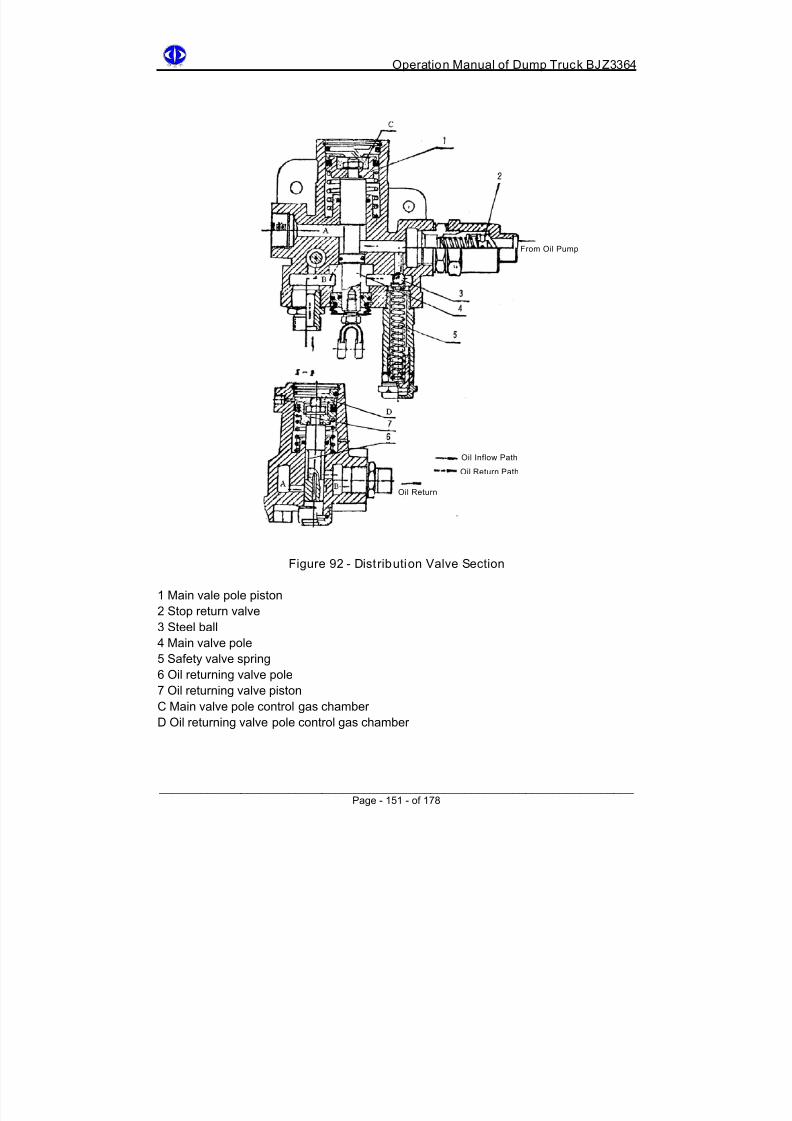
8/18/2019 d20 Bjz3364 Op Manual
http://slidepdf.com/reader/full/d20-bjz3364-op-manual 161/188
Operation Manual of Dump Truck BJZ3364
From Oil Pump
Oil Inflow Path
Oil Return Path
Oil Return
Figure 92 - Distribution Valve Section
1 Main vale pole piston
2 Stop return valve
3 Steel ball
4 Main valve pole
5 Safety valve spring
6 Oil returning valve pole
7 Oil returning valve piston
C Main valve pole control gas chamber
D Oil returning valve pole control gas chamber
______________________________________________________________________ Page - 151 - of 178

8/18/2019 d20 Bjz3364 Op Manual
http://slidepdf.com/reader/full/d20-bjz3364-op-manual 162/188
Operation Manual of Dump Truck BJZ3364
13.6.2 Assembly / Disassembly Notice And Technical Requirement
1. The coordinating clearance between valve pole and valve poles is better kept within
0.008-0.012mm, the maximum is 0.025mm. Otherwise there will be serious leakage.
2. After disassembly, replace all the O shape rubber sealing rings.3. The pressure of safety valve spring is limited within 8335 kpa. Under any circumstances
it must not exceed 9806 kpa or higher. Otherwise the whole hydraulic mechanism will
be damaged.
4. Strictly prohibit using loose fibrous cotton thread or cloth to wipe the parts, otherwise
there will be lag in the coordinating plane.
5. Strictly prohibit using gasoline or diesel oil to clean rubber sealing parts to prevent
metamorphoses.
13.7 Limit Valve
Position limit valve is an air distributor. It is control by a steel thread connecting to the
carriage. It is used to prevent over lifting of the carriage. When carriage is lifted to its limit
position, the oil going into hydraulic cylinder will be cut.
See Figure 93 for its structure KD.
Figure 93 - Position Limit Valve KD
It consists of iron casting shell (5) and valve pole (3). Valve pole has an open hole, the
steel thread passed through this hole and connects the carriage. The steel thread is
fastened under the valve pole using one pressing board (2) and two bolts (1). See Figure
93.
13.7.1 Working Principle
Usually the limit valve will not be in the working state. See Figure 94. the compressed air
from air reservoir passes through hole (1) but hole (1) and (2) are not in connection, so it
does not work. When carriage reaches its lifting limit, the steel thread will pull the valvepole and overcome the spring (7) force, then move it to the right (Figure 95).
______________________________________________________________________ Page - 152 - of 178

8/18/2019 d20 Bjz3364 Op Manual
http://slidepdf.com/reader/full/d20-bjz3364-op-manual 163/188
Operation Manual of Dump Truck BJZ3364
Thus the sealing ring (3) on the right will be moved to right hand side of hole (2), make hole
(1) and (2) in connection. The compressed air from air reservoir will passed through hole
(2) and goes into distribution valve main valve pole control gas chamber (Figure 92-C) to
push main valve pole, lifting will then be stopped.
13.7.2 Assembly / Disassembly Notice And Technical Requirement
1. Strictly prohibit using gasoline or diesel oil to wash rubber sealing parts.
2. Beware of dirt entering the coordinating plane.
3. When assembling, apply a layer of lubricants on valve and valve pole coordinating
plane.
Figure 94 - Limit Valve Not In Working State
1 Air entering hole 7 Spring
2 Air exit hole 8 Elastic block ring
3 Sealing ring 9 Dust proof cover
4 Felt ring 10 Valve pole
5 Steel thread fasten bolt 11 Valve
6 Pressing board 12 Air returning hole
Figure 95 - Limit Valve In Working State
1 Air entering hole 2 Air exit hole 12 Air returning hole
______________________________________________________________________ Page - 153 - of 178

8/18/2019 d20 Bjz3364 Op Manual
http://slidepdf.com/reader/full/d20-bjz3364-op-manual 164/188
Operation Manual of Dump Truck BJZ3364
13.8 Operation On Lift System
13.8.1 Operation Procedure
The control of oil pump is electromagnetic stretch type. By the carriage dump buttonswitch on the instrument panel, control the electromagnetic gas moving valve to makeelectromagnetic gas moving valve ventilates. Control power obtain device’s combinationalgay cylinder, gas cylinder piston will then push power obtain device swing arm to make oilpump driving axis engages gear.
The dump procedure is: firstly step down the clutch, move the gearlever to neutral position,
then connect the lifting electromagnetic valve switch. At this moment, the compressed air
from air reservoir will make oil pump gear engages gear through power obtain device
combinational gas cylinder. Oil pump starts rotating, and now can lift the carriage.
1. Lifting: put the lifting gas moving control valve handle into “lifting” position, at this
moment the gas valve closes, gas path is closed. Distribution valve main valve pole (A,
B) are in their original position as shown in Figure 96. The output high pressure oil from
oil pump will be transmitted to lifting cylinder’s oil entering pipe through distribution
valve (See the flow oil lifting oil shown in Figure 96), then input into lifting cylinder.
Under the effect of oil pressure the lifting cylinder will slowly move up the lift the
carriage.
When carriage dumps to its limit angle, limit steel thread B (Figure 97) will be pulled
tightly and move the limit valve pole to the right, see Figure 95. At this moment limitvalve will be open, compressed air goes into hydraulic distribution valve’s main valve
pole control chamber through pipe hole 1 and 2, push main valve pole, and then close
lifting cylinder oil entering pipe. Lifting will stop automatically.
If the oil pump keeps rotating, then the output oil from oil pump will flow back to oilcan
through distribution valve.
2. Descending: first cut off the lifting electromagnetic switch to make oil pump gear move
away from power obtain device combinational cover. Oil pump is not working at the
moment. Then put the lifting control handle to “descending” position, and gas valve
opens, and connects the compressed air to control distribution valve loop valve pole. At
this moment the oil from hydraulic cylinder will flow into oilcan through oil returning pipe.
Carriage will descend under the effect of its own weight.
3. Stop while lifting: follow the “lifting” procedure, stop the oil pump operation midway, at
this moment under the effect of distribution valve high pressure oil entrance stop return
valve, the oil in oil cavity will not flow back to oil pump. The oil in hydraulic cylinder will
support the carriage and make it stop.
______________________________________________________________________ Page - 154 - of 178
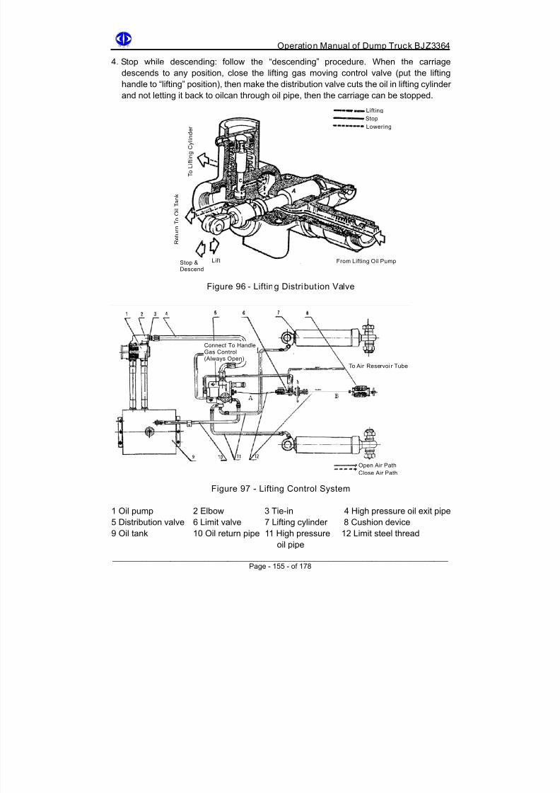
8/18/2019 d20 Bjz3364 Op Manual
http://slidepdf.com/reader/full/d20-bjz3364-op-manual 165/188
Operation Manual of Dump Truck BJZ3364
4. Stop while descending: follow the “descending” procedure. When the carriage
descends to any position, close the lifting gas moving control valve (put the lifting
handle to “lifting” position), then make the distribution valve cuts the oil in lifting cylinder
and not letting it back to oilcan through oil pipe, then the carriage can be stopped.
Lifting
Stop
T o L i f t i n g C y l i n d e r Lowering
R e t u r n T o O
i l T a n k
Lift From Lifting Oil PumpStop &Descend
Figure 96 - Lifting Distribut ion Valve
Connect To HandleGas Control(Always Open)
To Air Reservoi r Tube
Open Air Path
Close Air Path
Figure 97 - Lifting Control System
1 Oil pump 2 Elbow 3 Tie-in 4 High pressure oil exit pipe
5 Distribution valve 6 Limit valve 7 Lifting cylinder 8 Cushion device
9 Oil tank 10 Oil return pipe 11 High pressure 12 Limit steel threadoil pipe
______________________________________________________________________ Page - 155 - of 178

8/18/2019 d20 Bjz3364 Op Manual
http://slidepdf.com/reader/full/d20-bjz3364-op-manual 166/188
Operation Manual of Dump Truck BJZ3364
13.8.2 Operation And Adjustment Notice
1. Oil pump gear engagement and distribution valve’s gas path control pressure should be
higher than 450 kpa.2. When lifting is done, during the traveling, strictly prohibit closing the lifting
electromagnetic valve switch, strictly prohibit putting the lifting control handle to lifting
position, otherwise the oil pump will operate for a long time or carriage will be lifted,
causing accidents.
3. Check the steel thread, make sure it does not tangle the other parts, otherwise the
cushion spring will be damaged, causing accidents.
4. Check if the steel thread is loose. Especially take note of the adjustment of steel thread
installed on A segment (Figure 97). Make sure it is not too tight. It should have
looseness with 10-14mm. Usually this segment of steel thread will not function unless
gas path fails (limit valve is not functioning), then through this segment of steel thread
the distribution valve main valve pole will be pulled and hydraulic pressure cylinder oil
path will be closed, and let the carriage limits its position for the safety purpose.
5. One easy wat to check lifting limit angle (45º±2°) is after the carriage is lifted up, the
distance between the rear two cushion rubber blocks and vehicle frame rear rim
inclined surface should be about 50mm. See Figure 98.
6. The most important point of hydraulic system is that the oil must be clean, during the
assembly/disassembly must not knock, move at will or scratch the précised parts.
7. Do not adjust distribution valve’s safety valve spring at will, otherwise the parts will be
broken due to pressure overload.8. When repairing, strictly prohibit supporting the carriage on the soft ground. This method
is very unreliable, and it may cause deflection of carriage and lag in oil cylinder.
Carriage
Distribution Valve
Limit Valve
Vehicle Frame
Figure 98 - Check Lifting Limit Angle
______________________________________________________________________ Page - 156 - of 178
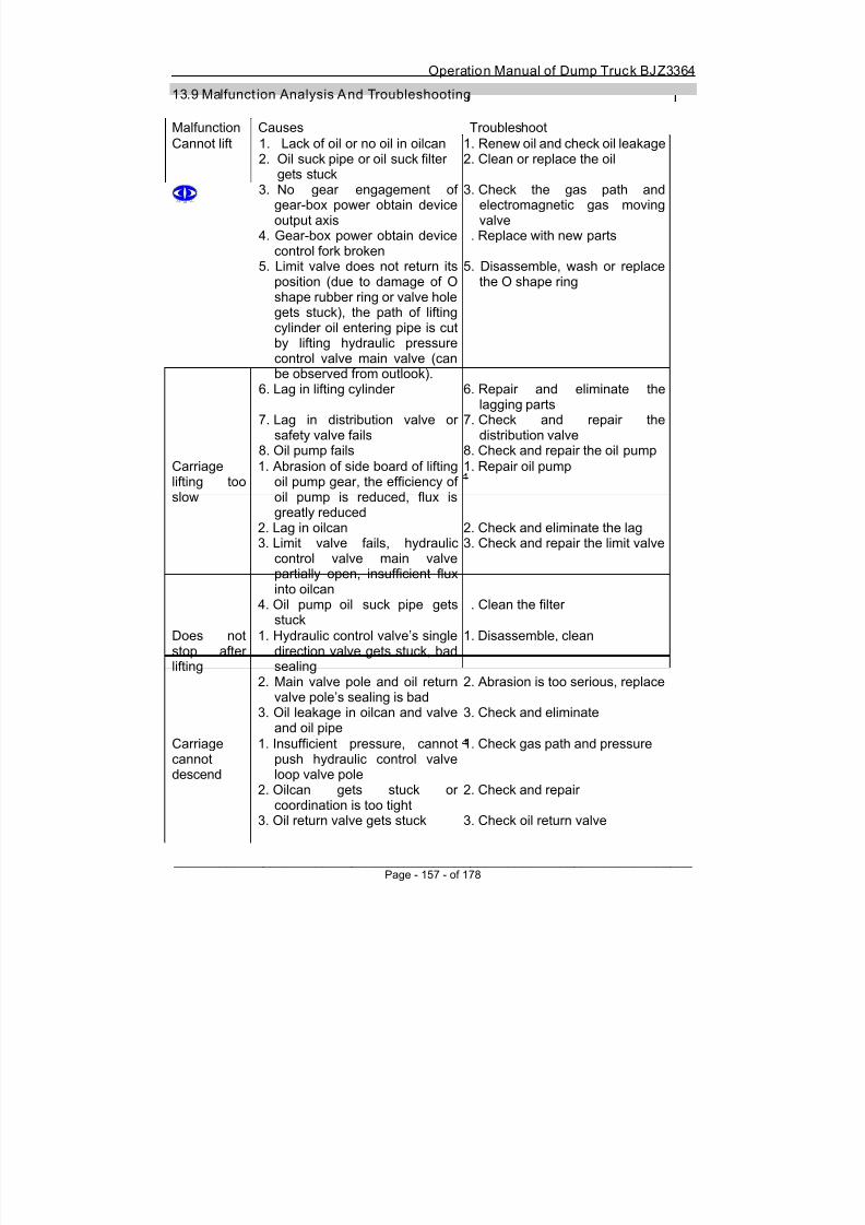
8/18/2019 d20 Bjz3364 Op Manual
http://slidepdf.com/reader/full/d20-bjz3364-op-manual 167/188
Operation Manual of Dump Truck BJZ3364
13.9 Malfunct ion Analysis And Troubleshooting
Malfunction Causes Troubleshoot
Cannot lift 1. Lack of oil or no oil in oilcan
2. Oil suck pipe or oil suck filtergets stuck3. No gear engagement of
gear-box power obtain deviceoutput axis
4. Gear-box power obtain devicecontrol fork broken
5. Limit valve does not return itsposition (due to damage of Oshape rubber ring or valve holegets stuck), the path of lifting
cylinder oil entering pipe is cutby lifting hydraulic pressurecontrol valve main valve (canbe observed from outlook).
6. Lag in lifting cylinder
7. Lag in distribution valve orsafety valve fails
8. Oil pump fails
1. Renew oil and check oil leakage
2. Clean or replace the oil
3. Check the gas path andelectromagnetic gas movingvalve
. Replace with new parts
5. Disassemble, wash or replacethe O shape ring
6. Repair and eliminate thelagging parts
7. Check and repair thedistribution valve
8. Check and repair the oil pump
Carriagelifting too
slow
1. Abrasion of side board of liftingoil pump gear, the efficiency of
oil pump is reduced, flux isgreatly reduced
2. Lag in oilcan3. Limit valve fails, hydraulic
control valve main valvepartially open, insufficient fluxinto oilcan
4. Oil pump oil suck pipe getsstuck
1. Repair oil pump
2. Check and eliminate the lag3. Check and repair the limit valve
. Clean the filter
Does notstop afterlifting
1. Hydraulic control valve’s singledirection valve gets stuck, badsealing
2. Main valve pole and oil returnvalve pole’s sealing is bad
3. Oil leakage in oilcan and valveand oil pipe
1. Disassemble, clean
2. Abrasion is too serious, replace
3. Check and eliminate
Carriagecannotdescend
1. Insufficient pressure, cannotpush hydraulic control valveloop valve pole
2. Oilcan gets stuck orcoordination is too tight
3. Oil return valve gets stuck
1. Check gas path and pressure
2. Check and repair
3. Check oil return valve
______________________________________________________________________ Page - 157 - of 178

8/18/2019 d20 Bjz3364 Op Manual
http://slidepdf.com/reader/full/d20-bjz3364-op-manual 168/188

8/18/2019 d20 Bjz3364 Op Manual
http://slidepdf.com/reader/full/d20-bjz3364-op-manual 169/188
Operation Manual of Dump Truck BJZ3364
Chapter 14
Vehicle Frame, Carriage, Cab And Driver Seat
14.1 Vehicle Frame
Vehicle frame is the basic framework of the vehicle. All the assemblies, parts and carriage
and cab are directly or indirectly assembled onto the frame.
When vehicle travels on a bumpy road, the frame may retort or transform or bend in
transverse plane. The transformation will change the relative position between each part
assembled on the vehicle frame and will affect its normal working. On the other hand, the
vehicle frame has to bear with the force and torque from all the assemblies, hence the
vehicle frame must have good rigidity, especially for heavy self dump vehicle since its load
is very heavy and its working environment is very bad. Thus, the obdurability of vehicle
frame is especially important. Meanwhile, the weight of the frame should be as light as
possible.
This vehicle frame is a C-type structure. Is has two carlings and four beams. The bumper
is connected to the frame by bolt, the structure girder is customized. Main body carling is
customized into C-type structure with dimension 240×l30×l2mm. For the part of carling
which has to bear with more force, use L-shape girder to strengthen it. Cover a flat board
on upper and lower wing to increase intensity. The external parts are plug welded onto
carling by prefabricate hole. Beam is an 8mm steel plate pressing group weldingcomponent.
The upper and lower reinforce boards of beam and L-shape girder are all plug welded onto
carling. The material of left and right carling and left and right auxiliary girder is 16MnL, the
rest use steer board material of 16Mn.
Frame’s front and rear ends are both welded with traction pin seat. The length of the frame
is changed from 6730 to 6450. The improved structure is more reasonable and is able to
provide a wider sight view for the driver.
14.2 Carriage
14.2.1 Carriage Structure And Funct ion Summary
Carriage is used to carry ores and clay and other cargo. It is a full steel plate welding
structure. Carriage chassis consists of two girders and five beams. The rear part of
motherboard is warped 8º30´´ so that it will prevent sliding of ores from the motherboard.
______________________________________________________________________ Page - 159 - of 178

8/18/2019 d20 Bjz3364 Op Manual
http://slidepdf.com/reader/full/d20-bjz3364-op-manual 170/188
Operation Manual of Dump Truck BJZ3364
The motherboard uses 15MnMoVNRe adjusting high strength steel plate. Its abrasion
resistance is 4-5 times compared to 16Mn steel plate. The side board and front board are
both welded using 8mm thick 16Mn steel plate.
Figure 99 - Connection Of Carriage, Lift ing Cylinder, Skip Bucket Axis &
Scratch Slate
1 Bolt 23 Oiling nuzzle 45 Support seat
2 Flat gasket ring 24 Dustproof cover 46 Nut3 Block cover 25 Bolt
4 Glue gasket 26 Shock absorbing glue gasket
5 Spring gasket ring 27 Spring gasket ring
6 Nut 28 Nut
7 Bolt 29 Pin
8 Position locating plate 30 Glue gasket ring
9 Nut 31 Flat gasket ring
10 Oiling nuzzle 32 Uncork pin
11 Upper pin 33 Dial rock pole
12 Dust proof cover 34 Bolt
13 Elastic block ring 35 Spring gasket ring
14 Active joint 36 Cover board
15 Hydraulic lifting cylinder 37 Lining
16 Bolt 38 Bracket
17 Elastic gasket ring 39 Bolt
18 Pin lock slice 40 Nut
19 Elastic block ring 41 Adjusting gasket ring
20 Dustproof cover 42 Shock absorbing gasket ring
21 Elastic block ring 43 Bolt22 Active joint 44 Carriage pin axis
______________________________________________________________________ Page - 160 - of 178
8/18/2019 d20 Bjz3364 Op Manual
http://slidepdf.com/reader/full/d20-bjz3364-op-manual 171/188
Operation Manual of Dump Truck BJZ3364
There is a protection plate in front of carriage. Its function is to protect the cab from
occasional dropping of rock and earth.
The exhaust gas from diesel engine can go to carriage’s exhaust gas intake gate, passes
through motherboard and front abdomen board and left and right abdomen board, andfinally it is discharged through the holes on left and right side plate. This is namely exhaust
gas warm-up device. It is used to prevent freezing of carriage when operating in winter.
There are two types of carriage heights. One is the usual carriage and is used for carrying
cargos like iron ore. The other is with additional height and is used for carrying cargos like
magnesium ore and limestone.
Carriage skip bucket (Figure 99) is fixed on two girders by upper support seat. Left and
right lifting cylinder’s upper pivot lifts up the carriage through lifting upper seat, and self
dump can be fulfilled. Three cushion rubber gaskets are installed on the bottom of two
girders to amortize the impact between carriage and vehicle frame. Two cushion gaskets
are installed on the back of carriage skip bucket axis and it will amortize when carriage is
lifted up.
A scratch slate is installed onto left and right of carriage rear bottom. It will automatically
get rid of the rocks and mud in between rear wheel’s two tyres.
A position locating bracket is installed on the left and right outer side of girder. It can
prevent carriage from swinging left and right.
14.2.2 Note When Using The Carriage
1. Make full use of safety lock. Safety lock is installed on the back of motherboard bottom.
When lifting the carriage and repairing the transmission, must take off the joint lock axis
from safety lock and put the joint plate into frame’s traction pin seat. This is for safety
purpose. When reparation is done, must restore the position of joint pin axis and joint
plate. Otherwise the safety lock will be pressed and transformed when skipping the
carriage in the future.
2. When disassembling the carriage, first take off the skip bucket pin from lifting cylinder,
then put the lifting cylinder on the rear tyre upside-down, finally take off the nut of
carriage skip bucket axis seat.
3. When sending the vehicle for repair, must check if the lifting position limit valve is safe
and reliable so that the bolt from skip bucket seat will not be snapped when lifting the
carriage.
______________________________________________________________________ Page - 161 - of 178

8/18/2019 d20 Bjz3364 Op Manual
http://slidepdf.com/reader/full/d20-bjz3364-op-manual 172/188
Operation Manual of Dump Truck BJZ3364
14.3 Cab
Cab assembly consists of floor assembly (2) and engine cover assembly (11).
Accumulator and air filter are installed on the right side of floor assembly.
A small ladder is fixed on the left side for the driver to climb up. Four walls of the cab are all
install with glass windows for better sight view.
Left and right windows can be opened the moved. Heatproof and shockproof dope is
applied on can’s head cover assembly and right side board, the right side board is also on
the left side on engine cover assembly, so it is also called left detachable cover assembly.
Front glass window (17) has electric wiper (14). There is a large tool box at the back of
driver seat. When installing air conditioning device, this tool box will be removed.
The fixing device (1) between cab and vehicle frame has 4 elastic bearing covered by
rubber and metal. If there is damage on elastic ring, the vibration of cab will become
serious and this will make driver tired more easily. Replace with new elastic bearing
assembly for safety and comfort.
Figure 100
______________________________________________________________________ Page - 162 - of 178

8/18/2019 d20 Bjz3364 Op Manual
http://slidepdf.com/reader/full/d20-bjz3364-op-manual 173/188
Operation Manual of Dump Truck BJZ3364
Cab is single sided left positioned. It is a whole metal structure. Cab frame is welded using
square steel tube and has more intensity compared with the old one.
1 Fixing device assembly 13 Ladder assembly2 Floor assembly 14 Wiper assembly
3 Front window assembly 15 Rearview mirror assembly
4 Front fence assembly 16 Door lock assembly
5 Side fence assembly 17 Front window assembly
6 Rear fence assembly 18 Left fence assembly
7 Head cover assembly 19 Right fence assembly
8 Cab door assembly 20 Right window rear glass
9 Mirror assembly 21 Rear window glass
10 Radiator cover assembly 22 Door window front glass
11 Engine cover assembly 23 Door wind rear glass
12 Front wing plate assembly
When checking and repairing the engine, first disassemble the right detachable cover
assembly and left detachable cover assembly.
14.4 Driver Seat
This driver seat is used for mine-use load truck with large
vibration.
The seat can move forward and backwards by 45mm. It is
suitable for driver with weight 50-100kg. The backrest can
be adjusted to 2, 8, and 14 degree.
It is connected to the cab by bolts. The outline of the seat is
shown in Figure 101.
Figure 101
1 Handle 2 Handgrip
A. How to adjust the seat:
1. Forward and backward adjustment of seat: when the driver sits on the seat, use right
heel to push the handle (2) to the left, left foot steps on the cab floor, apply force onto
the body forwards or backwards to make the seat move forwards or backwards,
then move away right foot from handgrip (2) then the seat will automatically fix itsposition.
______________________________________________________________________ Page - 163 - of 178

8/18/2019 d20 Bjz3364 Op Manual
http://slidepdf.com/reader/full/d20-bjz3364-op-manual 174/188
Operation Manual of Dump Truck BJZ3364
2. The elasticity of seat can be adjusted according to the weight of driver. How to adjust:
push the pallet on the handle (1) inwards, the push up the handle to increase
elasticity. When push the pallet outwards then push down the handle (1), the
elasticity will decrease. The elasticity is suitable when suddenly sit on the seat, the
compressing distance of the side plate should not exceed 10mm.3. How to adjust backrest: use both hands to lift up the backrest so that the flashboard
tine is facing one of the grooves of bolt shell, then insert the seat.
B. When adjusting the handle (1), must not continuously move the handle without limit,
especially when reducing the elasticity, the handle has to be pushed outwards. When
the seat elasticity is suitable, stop pushing the handle. Otherwise the pin on the bolt
may be broken and the adjusting screw pole will fall off. The seat can no more be lifted
and shock absorber will also be easily damaged.
C. Apply lubricants regularly on the sliding path and roller.
______________________________________________________________________ Page - 164 - of 178

8/18/2019 d20 Bjz3364 Op Manual
http://slidepdf.com/reader/full/d20-bjz3364-op-manual 175/188
Operation Manual of Dump Truck BJZ3364
Chapter 15
Electrical Device
Electrical device consists of one generator, two series accumulators, one electricity
distribution device and electric device. When diesel engine is working, it will drive the
generator to convert mechanical energy to electrical energy and then generate electricity.
The electricity generated is sent to electric devices and charge the accumulator. When
diesel engine works normally, the job of accumulator is the store the extra electricity for
backup use when engine goes off or in low speed operation.
The function of electricity distribution device is to connect all the electric device and
accumulator. Hence the distribution device consists of wires, circuit protection system and
switch.
The function of electric device is to convert electric energy into mechanical energy, heat
and light according to different requirements.
The instruction is divided into 4 parts:
Part 1: starting device, including accumulator, starting machine and starting switch.
Starting device is used for starting the diesel engine.
Part 2: electricity generating device, including generator and voltage regulator. This device
can produce electric energy to supply electric devices, and charge the accumulator.
Part 3: illuminating device.
Part 4: electricity distributing device, including circuit net and its protection.
15.1 Starting Device
Starting device consists of two 12V accumulator in series, one 24V starting machine and
one starting electromagnetic valve, two starting switch in series.
The function of starting device is to use accumulator’s electric energy to drive the diesel
engine’s rotation.
15.1.1 Working Principle
Turn the starting switch key (1) to position I (Figure 102) so “BAT” is connected with “ST”,
electricity will flow from Figure 102 (1) to starting switch (2) and pull in winding (3), it
makes the starting machine’s meshing pinion in mesh with flywheel teeth ring. At the sametime the connect-brake touch point (6) is closed.
______________________________________________________________________ Page - 165 - of 178
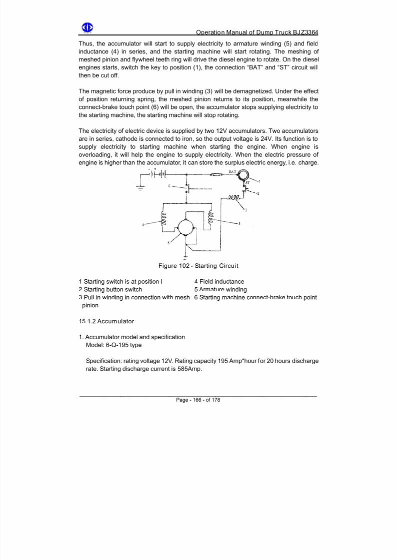
8/18/2019 d20 Bjz3364 Op Manual
http://slidepdf.com/reader/full/d20-bjz3364-op-manual 176/188
Operation Manual of Dump Truck BJZ3364
Thus, the accumulator will start to supply electricity to armature winding (5) and field
inductance (4) in series, and the starting machine will start rotating. The meshing of
meshed pinion and flywheel teeth ring will drive the diesel engine to rotate. On the diesel
engines starts, switch the key to position (1), the connection “BAT” and “ST” circuit will
then be cut off.
The magnetic force produce by pull in winding (3) will be demagnetized. Under the effect
of position returning spring, the meshed pinion returns to its position, meanwhile the
connect-brake touch point (6) will be open, the accumulator stops supplying electricity to
the starting machine, the starting machine will stop rotating.
The electricity of electric device is supplied by two 12V accumulators. Two accumulators
are in series, cathode is connected to iron, so the output voltage is 24V. Its function is to
supply electricity to starting machine when starting the engine. When engine is
overloading, it will help the engine to supply electricity. When the electric pressure of
engine is higher than the accumulator, it can store the surplus electric energy, i.e. charge.
Figure 102 - Starting Circui t
Starting switch is at position I 4 Field inductance
ection with mesh nnect-brake touch point
5.1.2 Accumulator
. Accumulator model and specification
pecification: rating voltage 12V. Rating capacity 195 Amp*hour for 20 hours discharge
1
2 Starting button switch 5 Armature winding
3 Pull in winding in conn 6 Starting machine co
pinion
1
1
Model: 6-Q-195 type
S
rate. Starting discharge current is 585Amp.
______________________________________________________________________ Page - 166 - of 178

8/18/2019 d20 Bjz3364 Op Manual
http://slidepdf.com/reader/full/d20-bjz3364-op-manual 177/188
Operation Manual of Dump Truck BJZ3364
______________________________________________________________________
2. Maintenance of accumulator
ularly. This is necessary for the efficiency and lifespan of
. Observe for any electrolyte leakage from accumulator outer shell.nd connection of
umulator cover often, wipe off the electrolyte on the cover, free
d liquid level. The liquid level can be
n
lectrolyte proportion is measured using proportion meter. Take note that when
able 15-1 Electrolyte proportion under conversion of 15ºC correction
e
Carry out the maintenance reg
accumulator.
12. Check if the assembly of accumulator on the vehicle, lead tie-in a
electric pilot is tight.
3. Clean the dust on acc
the liquid renew cover’s gas block hole, clean oxide on electric pilot and wire tie-in,
wash them, apply Vaseline to prevent erosion.
4. Check and adjust the proportion of electrolyte an
measured using glass tube. Electrolyte liquid level should be 10-15mm higher than
the pole plate. If electrolyte is insufficient, add in distilled water. Do not add in dilute
sulphuric acid unless the decrease in liquid level is caused by spill of electrolyte.
5. Check the discharge extent of accumulator, if it exceeds the regulated valve the
charge. The charging condition of accumulator can be obtained from measuring the
electrolyte proportion.
E
measuring the proportion, also measure the temperature of the electrolyte. Compare the
measured proportion with temperature with table 15-1 and convert to proportion under
l5ºC. For example, electrolyte temperature is 30ºC and measured proportion is 1.28,
converted to 15ºC proportion is 1.28+0.01=1.29.
T
Measured +45 +30 +15 0 -15 -30 -45temperatur
Correction ofproportion meter’sreading
0.02 0 0 -0.01 -0.02 -0.03 0.04
For every 0.01 reduction in proportion, it is equivalent to accumulator discharing %6. If the
el must reach the required level. On the
hen use the accumulator in winter, make sure the accumulator is fully charge so that
electrolyte proportion of charged accumulator is known, the discharge extent can then beestimated from measured electrolyte proportion.
When measuring the proportion, the electrolyte lev
other hand, when diesel engine starts and distilled water is added for a few times, should
not measure the proportion immediately.
W
then proportion will not become too low and get frozen, which will in turn crack the
machine shell, causing problem in pole plate. Because in winter, the capacity of
accumulator decreases, it is necessary to do the warm-up of starting machine. Every
switch on time should not exceed 5 seconds. If need to use continuously, rest for 15seconds then carry on.
Page - 167 - of 178

8/18/2019 d20 Bjz3364 Op Manual
http://slidepdf.com/reader/full/d20-bjz3364-op-manual 178/188
Operation Manual of Dump Truck BJZ3364
______________________________________________________________________
accumulator’s malfunction, causes and troubleshoot.
5.1.3 Starting Machine
he function of starting machine is to drive crank shaft’s rotation when diesel engine
his vehicle used 40MT24V starting machine produced by DeIco-Remy. It is fixed on the
s meshing mechanism and closing
. Working principle
Starting machine has 4 poles, field inductance in series, and uses accumulator for
Once the diesel engine starts, starting switch returns to its original position. Power
able 15-2
Causes Troubleshoot
3. Refer to table 15-2 for
1
Tstarts.
T
diesel machine flywheel outer shell using three bolts.
The electromagnet 7 used for controlling mesh pinion’
starting machine connect-brake touch pint is fixed on the starting machine stator shell
using 4 bolts.
1
electricity supply. When starting switch is in position II and starting button switch is
pressed, the electricity gets connected. Magnetic force is then produced in pull in
winding active iron core. It drives the pinion through double shoulder pole, make
driving pinion in mesh with flywheel ring. At this moment the connection pole (14)
closes (Figure 103), starting machine will drive diesel engine to rotate. Magnetic
connection is produced by passing the electricity through starting machine’s field
inductance. Electricity also passes through armature winding and produce rotating
distance. This rotating distance drives the rotor. Due to the mesh of upper gear andflywheel teeth ring, the rotor will drive diesel engine’s flywheel to rotate.
source is cut off, pull in winding is demagnetized. Under the effect of position returning
spring, the double shoulder pole will make mesh pinion go back to its position.
Meanwhile, the connection pole (14) is cut off, no electricity in starting engine and
rotation stops. After diesel engine starts, driving pinion and flywheel teeth ring
immediately fall off each other so that the starting machine will not be damaged.
T
Malfunction
Accumulatordoes notsupplyelectricity
lectricity in
f connecti
. Bad grounding
. Electrolyte liquid level too
. Fix the connection pole, if eroded
3. Clean the grounding and fix the
4. Add distilled water
1. No eaccumulator
2. Looseness o on 2pole
3
4low
1. Charge
then replace
grounding
Page - 168 - of 178

8/18/2019 d20 Bjz3364 Op Manual
http://slidepdf.com/reader/full/d20-bjz3364-op-manual 179/188

8/18/2019 d20 Bjz3364 Op Manual
http://slidepdf.com/reader/full/d20-bjz3364-op-manual 180/188
Operation Manual of Dump Truck BJZ3364
Figure 103 - Starting Machine Circuit Principle
1 Driving pinion 11 Amperemeter
2 Position returning spring 12 Connection pole
3 Double shoulder pole 13 Contacting plate
4 Active iron core 14 Connection pole
5 Positioning winding 15 Ground6 Pull in winding 16 Starting machine
7 Connection pole 17 Accumulator
8 Starting button switch 18 Brass cover
9 Starting switch 19 Starting electromagnetic valve
10 Fuse
2. Maintenance
1. Drop machining oil on the oil path sealed by bolts, lubricate 3 bearings.
2. Check the abrasion condition of electric brush, keep the commutating slice clean.
3. Check if the connection is tight, especially on grounding tie-in.
______________________________________________________________________ Page - 170 - of 178

8/18/2019 d20 Bjz3364 Op Manual
http://slidepdf.com/reader/full/d20-bjz3364-op-manual 181/188
Operation Manual of Dump Truck BJZ3364
3. Malfunction, Causes And Troubleshooting
Malfunction Causes Troubleshoot
Driving pinion
does notmesh
1. No electricity in accumulator
2. No electricity in pull in winding
3. Short circuit or broken circuit inpull in winding
4. Double shoulder pole broken ortransformed
5. Abrasion of gear
1. Charge
2. Check circuit, fuse joint andstarting switch3. Open pull in winding shell,
tie-in, replace if necessary4. Replace
5. Replace
Driving pinionnot rotating orcannot drivethe diesel
engine aftermeshing
1. Partial discharge ofaccumulator
2. Connection pole 14disconnected
3. Abrasion of brush orinsufficient spring force ofbrush frame
4. Rectifier oxidized or dirty5. Armature winding or field
inductance short circuited orbroken circuited
1. Charge
2. Open pull in winding shell,check the joint
3. Replace
4. Clean and brush rectifier5. Disassemble starting
machine and check wiringon the platform, replacewhen necessary
Driving pinionand flywheelteeth ring do
no getdisconnected
1. Insufficient spring force in gearpositioning spring
2. Pinion gets stuck in spline
groove3. Transformation of driving
pinion’s teeth or teeth ring4. Long charging of pull in winding
1. Replace the spring
2. Disassemble the gear and
check3. Replace the broken parts
4. Check starting switch’s joint
15.1.4 Starting Electromagnetic Valve
The function of starting electromagnetic valve (Figure 104) is to supply electricity for
engine when starting.
When need to start the starting machine, start switch is turned in position II, press the
starting button switch, connect the power source, the electricity passes electromagnetic
valve’s small connection pole (1), reaches the cathode, makes electromagnet produce
suction to suck the valve to connect connection pole (2) and (3). The electricity supplied by
accumulator passes through connection pole (2) (3) and flows into starting machine’s
positioning winding and pull in winding, makes the starting machine start working.
Once the diesel engine starts, starting switch returns to its original position, pinion power
source is cut, electromagnet suction force disappears, valve returns its position under the
effect of spring. Connection pole (2) (3) get disconnected, starting electromagnetic valvefinishes working.
______________________________________________________________________ Page - 171 - of 178

8/18/2019 d20 Bjz3364 Op Manual
http://slidepdf.com/reader/full/d20-bjz3364-op-manual 182/188
Operation Manual of Dump Truck BJZ3364
Figure 104 - Starting Electromagnetic Valve Switch
1 Connection pole 5 Electromagnet
2 Connection pole 6 Valve
3 Connection pole 7 Spring
4 Pinion
By using starting electromagnetic valve, we can prevent burning of starting machine joint
caused by large current. This burning will cause pull in winding long time electrified and
driving pinion and flywheel teeth ring will not get disconnected.
15.1.5 Starting Switch
The function of starting switch is to connect and disconnect starting machine circuit. It can
also cut the circuit for illuminating and other electric devices then vehicle does not start.
Starting switch has 3 positions (Figure 105).
Figure 105 - Starting Switch
Position 0: when vehicle is not starting, all touch points open
Position I: electrify all the electric devices except for starting machine pull in winding
Position II: electrify all the devices, field inductance of starting machine pull in windingStarting switch is fixed on the instrument panel using loop nut.
______________________________________________________________________ Page - 172 - of 178

8/18/2019 d20 Bjz3364 Op Manual
http://slidepdf.com/reader/full/d20-bjz3364-op-manual 183/188
Operation Manual of Dump Truck BJZ3364
The starting switch uses two series. One is on ignition switch, the other is on starting
button. The purpose is to prevent operational mistake. Only when two switches close
simultaneously it will work.
The causes of malfunction and troubleshoot:Malfunction Causes Troubleshoot
Starting switch cannotclose the circuit
Disconnection in touchpoint and connectionpole
Connect them, fix thetouch point
Starting switch cannotopen the circuit
Inner touch points arewelded together
Replace the startingswitch
15.2 Electr ical Generating Device
The function of this device is to convert the mechanical energy into generator’s electric
energy, for charging accumulator, fulfilling the requirements of electric device.
The current during normal traveling of vehicle is partially absorbed by accumulator and
partially used by electric devices.
If the device works normally it will output a maximum 28V voltage, the minimum voltage
should be equal to the voltage of accumulator.
The generator used for this vehicle is self commuted. It has inner touch point free pressure
adjusting generator. This kind of whole generator has good voltage adjusting precision,
endurance and shockproof. On the other hand, the generator and pressure adjusting
device are assembled together so there is no external wire, thus relatively there is less
malfunction.
In the whole assembly, the only part in motion is rotor. Its one end is fixed on generator’s
driving end by roller bearing, the other end is fixed on generator’s rectifying end by roller
bearing.
Magnetic wire, stator wire and 6 rectifying diode and adjusting device circuit sub-assembly
are all fixed. Fan is installed on the driving end for cooling purpose. There is a large
lubricant reservoir for good lubrication.
Only one live wire is needed to connect the generator and accumulator. “R” output tie-in is
used by some communicating devices. Meanwhile it can be used for magnetism charge
after generator is disassembled and repaired.
______________________________________________________________________ Page - 173 - of 178

8/18/2019 d20 Bjz3364 Op Manual
http://slidepdf.com/reader/full/d20-bjz3364-op-manual 184/188
Operation Manual of Dump Truck BJZ3364
(28V DC, Max 2A Curr ent)
______________________________________________________________________
Figure 106 - Generator Circuit Principle
15.2.1 Working Principle
1. R(W) end commutes through one of the 4,5,6 silicon pipe, forms half wave
commuting voltage with ground. So its output signal is 14V DC pulse voltage
(maximum load cannot exceed 2A). R(W) end is used to connect rev meter.
2. B+ end commutes in full wave through4,5,6 and 7,8,9 silicon pipe. It passes
through filter wave capacitor C and outputs 28V DC current. When electric switch K
is closed, it charges the accumulator or supplies electricity for it.
3. D+ end commutes in full wave through 1,2,3 and 4,5,6 silicon pipe and outputs 20V
DC voltage (maximum load is 2A). D+ end is used to connect charge indicator and
supply generator’s self-excitation current.
Grounding
Armature
Winding
Grounding
14V Direct Current ElectricalPressure Max 2A Current
Electrical Switch
Supply Magnetic Current Or
Charge Indication
Provides Rotational Speed Signal OrChange Indication
F i e l d I n d u c t a n c e
A d j u s t i n g D e v i c e
Page - 174 - of 178

8/18/2019 d20 Bjz3364 Op Manual
http://slidepdf.com/reader/full/d20-bjz3364-op-manual 185/188
Operation Manual of Dump Truck BJZ3364
15.2.2 Malfunct ions, Causes And Troubleshooting
Malfunction Causes Troubleshoot
Insufficient electricity in
accumulator
1. Accumulator fails
2. Circuit loose
3. Engine fails
1. Check, repair or replace the
accumulator2. Check the joints of circuit,keep the joint pivot clean andtight, accumulator surface dryand clean
3. Check and repair
Too much electricity inaccumulator
1. Engine fails 1. Check and repair the enginevoltage adjusting board
15.2.3 Generator maintenance
Since AC current generator is different from DC current generator, take note of the
following points during use:
1. No short circuit of cathode and anode of generate and accumulator, otherwise
commuting components will be burnt.
2. Switch on the power switch when vehicle stops driving, cut off the circuit, otherwise
accumulator will keep discharging into field inductance and burn it.
3. After accumulator is fully charged, charging current will automatically decrease.
When engine operates with middle speed, the charging current is small or zero, this
does not mean the charging system has malfunction. Because when there is
sufficient electricity in accumulator and engine and voltage adjusting device are all
normal, it is just the accumulator is fully charged. If the ampere meter points to
discharge direction, it shows that there is malfunction in engine.
______________________________________________________________________ Page - 175 - of 178

8/18/2019 d20 Bjz3364 Op Manual
http://slidepdf.com/reader/full/d20-bjz3364-op-manual 186/188
Operation Manual of Dump Truck BJZ3364
15.3 Illumination Device
15.3.1 Summary
Illumination device is used for:1. Indicate vehicle width (width indicator)
2. Indicate turning direction (turning indicator) or brake (stoplight)
3. Light up front and rear of vehicle (headlight, dipped headlight and back working
light)
Illumination device consists of:
2 headlights
2 back working lights
2 front small lights (indicate width and turning)
2 back combinational lights (indicate width, turning and brake)
1 top light
1 socket for manual working light
2 front foglights
15.3.2 Malfunct ion, Causes And Troubleshooting
Malfunction Causes Troubleshoot
One or some illumination
device do not light up
1. Broken fuse
2. Broken light socket wire
3. Broken light4. Circuit short or open
1. Replace the fuse
2. Connect the brokencircuit3. Change lights4. Change wire, eliminate
short circuit
Note: must not use high voltage or other types of light to replace, this is because it may
waste too much electricity, or cause overload in electric device, or reduce the lighting
effect.
15.4 Electrical Distribution Device
15.4.1 Fuse Box
1. Summary
In the fuse box there are 8 fuses and they are responsible for protection of all electric
devices. The box is installed on the front side of instrument panel. The basic protected
wires are shown below in the table.
______________________________________________________________________ Page - 176 - of 178

8/18/2019 d20 Bjz3364 Op Manual
http://slidepdf.com/reader/full/d20-bjz3364-op-manual 187/188
Operation Manual of Dump Truck BJZ3364
2. Working principle
When there is short circuit, the current increases and exceeds the rating melt current
of fuse, and fuse melts. Hence the circuit with fuse will be cut off.
Circuits protected by fuses (BJZ3364)
Serial#
Capacity Circuit under protection
12345
678
50A30A6A6A6A
6A6A6A
Generator AccumulatorHeadlight, width indicatorWiper system, horn systemTurning system, instrument panel indicator, air pressurewarning indicatorFoglight, back light, lifting systemFuel systemBrake system, fan system, working light, top light
Note: before replacing the fuse, first find out the cause, must not use fuses with high
melting point.
15.4.2 Circuit
1. Summary
Electric device is connected to power source through wires. The circuit consists of
some copper insulating wires. Its load area is proportional to circuit load.
1. Dial wiring harness: supply electricity to the meters, indicators, and switch buttons
on the instrument panel.
2. Chassis wiring harness: except for front and rear light and odometer, all the electric
device of chassis is supplied by chassis wiring harness.
3. Front light wiring harness: supply electricity for headlight, foglight and turning light.
4. Rear light wiring harness: supply electricity for back combinational light, back
working light and transmit odometer sensor’s inductance signal.
For easy assembly, rear light wiring harness is divided into rear light wiring harness
(1) and rear light wiring harness (2).
Dial wiring harness, chassis wiring harness, front light wiring harness and rear light wiring
harness are connected through 4 connection devices.
There are also two thick wires in the circuit. They are used for connecting “electric bottle
and main gate device”, “electric bottle and starting”, and hence form the whole circuit
system.
Each wire is labeled. The label number used is according to electric circuit principle. If
there is malfunction of the circuit, find out the cause according to “electric circuit principle”and do the troubleshooting.
______________________________________________________________________ Page - 177 - of 178

8/18/2019 d20 Bjz3364 Op Manual
http://slidepdf.com/reader/full/d20-bjz3364-op-manual 188/188
Operation Manual of Dump Truck BJZ3364