D10024 Analog Fire Alarm Control Panel User Manuals/D100… · D10024 Analog Fire Alarm Control...
24
D10024 Analog Fire Alarm Control Panel Operator’s Guide 61 62 63 64 65 66 67 68 41 42 43 44 21 1 22 23 24 2 3 4 45 46 47 48 25 5 26 27 28 6 7 8 System Reset Trouble Silence 77 57 37 69 70 71 72 73 74 75 76 49 50 51 52 29 30 31 32 9 10 11 12 53 54 55 56 33 34 35 13 14 15 36 16 78 79 80 58 59 60 38 39 17 18 19 40 20 Letters Numbers Alarm Silence Manual Alarm ENTER YES Keyword NO D10024 ALARM TROUBLE TROUBLE ALARM ALARM TROUBLE TROUBLE ALARM POWER SYSTEM TROUBLE TROUBLE SILENCED ALARM SILENCED POINT BYPASSED ALARM System Reset Trouble S ilen ced Silence Alarm Alarm Manual Keypad Enable Disable Keypad
Transcript of D10024 Analog Fire Alarm Control Panel User Manuals/D100… · D10024 Analog Fire Alarm Control...

D10024 Analog Fire Alarm Control Panel
Operator’s Guide
61 62 63 64 65 66 67 68
41 42 43 44
21
1
22 23 24
2 3 4
45 46 47 48
25
5
26 27 28
6 7 8
SystemReset
TroubleSilence
77
57
37
69 70 71 72 73 74 75 76
49 50 51 52
29 30 31 32
9 10 11 12
53 54 55 56
33 34 35
13 14 15
36
16
78 79 80
58 59 60
38 39
17 18 19
40
20
LettersNumbers
AlarmSilence
ManualAlarm ENTER YES
Keyword
NO
D10024
ALARMTROUBLE
TROUBLEALARM
ALARMTROUBLE
TROUBLEALARM
POWER
SYSTEM TROUBLE
TROUBLE SILENCED
ALARM SILENCED
POINT BYPASSED
ALARM
SystemReset
TroubleSilenced Silence
AlarmAlarm
Manual KeypadEnable
DisableKeypad

D10024
D10024 Operator’s Guide46521C Page 2 Copyright © 2001 Radionics
This page is intentionally blank.

D10024
D10024 Operator’s GuideCopyright © 2001 Radionics Page 3 46521C
Contents
Contents
1.0 Notices ................................................................................................................................................................................. 51.1 General Notices .................................................................................................................................................................... 51.2 FCC Notice............................................................................................................................................................................ 51.2.1 Part 15 ................................................................................................................................................................................... 51.3 UL/NFPA Notice .................................................................................................................................................................... 52.0 Overview .............................................................................................................................................................................. 72.1 System Overview .................................................................................................................................................................. 72.2 Control Level Distinction ...................................................................................................................................................... 82.3 Passcodes ............................................................................................................................................................................. 82.4 Controls and Displays .......................................................................................................................................................... 83.0 Control Level 1 (Display Functions) .............................................................................................................................. 113.1 Power Conditions................................................................................................................................................................ 113.2 Trouble Conditions.............................................................................................................................................................. 113.3 Alarm Conditions ................................................................................................................................................................ 114.0 Control Level 2 (Controller Functions) ......................................................................................................................... 134.1 Power Conditions................................................................................................................................................................ 134.1.1 Power Failure Signal .......................................................................................................................................................... 134.1.2 Power Failure Signal Response ........................................................................................................................................ 134.2 Trouble Conditions.............................................................................................................................................................. 144.2.1 Trouble Signals ................................................................................................................................................................... 144.2.2 Trouble Signal Response ................................................................................................................................................... 144.3 Alarm Conditions ................................................................................................................................................................ 144.3.1 Alarm Signals ...................................................................................................................................................................... 144.3.2 Alarm Signal Response ...................................................................................................................................................... 144.4 System Operation (Main Menu Options) ........................................................................................................................... 154.4.1 System Tests ....................................................................................................................................................................... 154.4.1.1 LEDs Test ............................................................................................................................................................................ 154.4.1.2 LCD Test .............................................................................................................................................................................. 154.4.1.3 Zones Test ........................................................................................................................................................................... 154.4.2 Time Setting ........................................................................................................................................................................ 174.4.3 Enable/Disable Functions .................................................................................................................................................. 174.4.3.1 Enable/Disable by Zone ..................................................................................................................................................... 174.4.3.2 Enable/Disable Individual Detection Devices (Inputs) ..................................................................................................... 174.4.3.3 Enable/Disable Panel Keys ................................................................................................................................................ 174.4.3.4 Enable/Disable Delayed Day Mode ................................................................................................................................... 184.4.3.5 Enable/Disable Relays ....................................................................................................................................................... 184.4.4 Print Functions .................................................................................................................................................................... 194.4.4.1 Print Devices ....................................................................................................................................................................... 194.4.4.2 Print Events (Event Log) .................................................................................................................................................... 194.4.4.3 Print Mode ........................................................................................................................................................................... 194.4.4.4 Print Direction ..................................................................................................................................................................... 194.4.4.5 Print Disabled ...................................................................................................................................................................... 194.4.5 View Functions.................................................................................................................................................................... 194.4.5.1 View Devices ....................................................................................................................................................................... 194.4.5.2 View Event Log ................................................................................................................................................................... 194.4.5.3 View Faults .......................................................................................................................................................................... 194.4.5.4 View Outputs ....................................................................................................................................................................... 204.4.5.5 View Disablements ............................................................................................................................................................. 204.4.5.6 View System Events ........................................................................................................................................................... 205.0 Control Level 3 (Programmer Functions) ..................................................................................................................... 215.1 Enable/Disable Sounders (NAC Devices) ........................................................................................................................ 21Index .................................................................................................................................................................................................. 23

D10024
D10024 Operator’s Guide46521C Page 4 Copyright © 2001 Radionics
Figures and Tables
Figures
Figure 1: D10024 Fire Alarm Control Panel ....................................................................................................................................... 7Figure 2: D10024 Controls and Displays ........................................................................................................................................... 9Figure 3: Control Level 2, Entry Menu 1 .......................................................................................................................................... 13Figure 4: Control Level 2, Entry Menu 2 .......................................................................................................................................... 13Figure 5: Main Menu .......................................................................................................................................................................... 13Figure 6: Enable Menu ...................................................................................................................................................................... 13Figure 7: Main Menu .......................................................................................................................................................................... 15Figure 8: Test Menu ........................................................................................................................................................................... 15Figure 9: Zone Test Menu 1 .............................................................................................................................................................. 15Figure 10: Zone Test Menu 2 ............................................................................................................................................................ 16Figure 11: Zone Test Menu 3 ............................................................................................................................................................ 16Figure 12: Zone Test Menu 4 ............................................................................................................................................................ 16Figure 13: Main Menu ........................................................................................................................................................................ 16Figure 14: Enable/Disable Menus .................................................................................................................................................... 17Figure 15: Outputs Menu .................................................................................................................................................................. 18Figure 16: Main Menu ........................................................................................................................................................................ 18Figure 17: Print Menu ........................................................................................................................................................................ 19Figure 18: View Menu ........................................................................................................................................................................ 19Figure 19: Outputs Submenu ............................................................................................................................................................ 21
Tables
Table 1: Control Key Functions ........................................................................................................................................................... 8Table 2: Alphanumeric and Program/Interactive Key Functions ...................................................................................................... 9Table 3: System Event and Status LEDs ......................................................................................................................................... 10

D10024
D10024 Operator’s GuideCopyright © 2001 Radionics Page 5 46521C
Notices
1.0 Notices1.1 General Notices
These instructions contain procedures to follow in order to avoid personal injury and/or damage to the equipment.
NFPA 72 requires a complete system-wide functional test be performed following any modifications, repair,upgrades or adjustments made to the system’s components, hardware, wiring, programming and software/firmware.
The material and instructions covered in this installation guide have been carefully checked for accuracy and arepresumed to be reliable. However, the manufacturer assumes no responsibility for inaccuracies and reserves the rightto modify and revise this installation guide without notice.
This manual covers the operation of the D10024 Analog Fire Alarm Control Panel (FACP). See the D10024 InstallationGuide (P/N: 46482) for instructions on the installation of the D10024.
1.2 FCC Notice1.2.1 Part 15
This equipment has been tested and found to comply with the limits for a Class A digital device, pursuant to Part 15 ofthe FCC Rules. These limits are designed to provide reasonable protection against harmful interference in a commercialinstallation. This equipment generates, uses and can radiate radio frequency energy, and, if not installed in accordancewith the instructions, may cause harmful interference to radio communications. However, there is no guarantee thatinterference will not occur in a particular installation. If this equipment does cause harmful interference to radio ortelevision reception, which can be determined by turning the equipment on and off, the user is encouraged to try tocorrect the interference by one or more of the following measures:
1) Reorient or relocate the receiving antenna.
2) Increase the separation between the equipment and the receiver.
3) Connect the equipment into an outlet on a circuit different from that to which the receiver is connected.
4) Consult the dealer or an experienced radio/TV technician for help.
1.3 UL/NFPA NoticeRadionics’ D10024 Analog Fire Alarm Control Panel is UL Listed for NFPA 72, Central Station and Remote Station.
All references to NFPA and related requirements are based upon compliance with the 1993 edition of NFPA 72, NationalFire Alarm Code. Since installation specifications are nearly always based upon a specific edition of a standard whichhas been legally adopted by the Authority Having Jurisdiction (AHJ), earlier editions of NFPA standards will generallyapply. Consult with the appropriate AHJ for confirmation.

D10024
D10024 Operator’s Guide46521C Page 6 Copyright © 2001 Radionics
Notes:
Notices
D10024
D10024 Operator’s GuideCopyright © 2001 Radionics Page 7 46521C
2.0 Overview2.1 System Overview
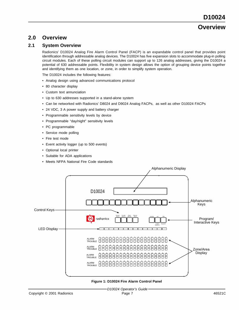
Radionics’ D10024 Analog Fire Alarm Control Panel (FACP) is an expandable control panel that provides pointidentification through addressable analog devices. The D10024 has five expansion slots to accommodate plug-in pollingcircuit modules. Each of these polling circuit modules can support up to 126 analog addresses, giving the D10024 apotential of 630 addressable points. Flexibility in system design allows the option of grouping device points togetherand identifying them as one location, or zone, in order to simplify system operation.
The D10024 includes the following features:
• Analog design using advanced communications protocol
• 80 character display
• Custom text annunciation
• Up to 630 addresses supported in a stand-alone system
• Can be networked with Radionics’ D8024 and D9024 Analog FACPs, as well as other D10024 FACPs
• 24 VDC, 3 A power supply and battery charger
• Programmable sensitivity levels by device
• Programmable “day/night” sensitivity levels
• PC programmable
• Service mode polling
• Fire test mode
• Event activity logger (up to 500 events)
• Optional local printer
• Suitable for ADA applications
• Meets NFPA National Fire Code standards
61 62 63 64 65 66 67 68
41 42 43 44
21
1
22 23 24
2 3 4
45 46 47 48
25
5
26 27 28
6 7 8
SystemReset
TroubleSilence
77
57
37
69 70 71 72 73 74 75 76
49 50 51 52
29 30 31 32
9 10 11 12
53 54 55 56
33 34 35
13 14 15
36
16
78 79 80
58 59 60
38 39
17 18 19
40
20
LettersNumbers
AlarmSilence
ManualAlarm ENTER YES
Keyword
NO
D10024
ALARMTROUBLE
TROUBLEALARM
ALARMTROUBLE
TROUBLEALARM
Alphanumeric Display
AlphanumericKeys
Program/Interactive Keys
Zone/AreaDisplay
LED Display
Control Keys
Figure 1: D10024 Fire Alarm Control Panel
Overview

D10024
D10024 Operator’s Guide46521C Page 8 Copyright © 2001 Radionics
2.2 Control Level DistinctionThe D10024 has three available control levels. At all three levels, the LED display indicates condition, the Zone/AreaLEDs indicate location and determined alarm/trouble information is displayed alphanumerically.
• Control Level 1 (Display Level): Inhibits the system control keys, limiting the front panel function to annunciation.
• Control Level 2 (Controller Level): Allows system control for Fire Drill, Alarm Silence, Trouble Silence and SystemReset. This level also allows Test and Enable/Disable operations, but does not allow access to configuration orprogramming functions. At Control Level 2, the alphanumeric display becomes interactive and prompts for systemchecks, log functions and key status. Control Level 2 is reached by entering a passcode from Control Level 1.
• Control Level 3 (Programmer’s Level): Allows full system configuration information and is used to program thesystem or modify the program. Control Level 3 is reached by passcode from Control Levels 1 or 2. See the AnalogFire Alarm Control Panels Programming Guide (P/N: 38789) for more information on Control Level 3.
2.3 PasscodesTen passcodes are available for D10024 Controllers. Passcodes are programmable. The Control Level 2 passcode isassigned or changed from Control Level 3, but will not allow access to Control Level 3. See the Analog Fire AlarmControl Panels Programming Guide (P/N: 38789) for more information on programming and assigning passcodes fromControl Level 3.
The default Control Level 2 passcode is 1234. Be sure to change the Control Level 2 passcode in order toprovide a higher level of panel security. See Section 7.4 in the Analog Fire Alarm Control Panels ProgrammingGuide (P/N: 38789) to modify the Control Level 2 passcode.
2.4 Controls and DisplaysThe D10024 has two rows of control keys and three display areas. The upper row of keys, the alphanumeric keys,normally function as number keys. They can be toggled to letter keys or number keys by pressing the [Letters/Numbers]key in the program/interactive keys row. The [Shift] key at the left end of the alphanumeric keys toggles between theupper and lower rows of letters. Hold the [Shift] key while pressing another key to enter the bottom letter. The controlkeys row contains four system control keys and three program/interactive keys.
See Tables 1 and 2 for key descriptions and Figure 2 for key locations.
Key Label Function
Fire Drill Turns on all NAC devices.
Alarm SilencePress to silence all NAC devices.
Press again to activate all NAC devices.
Trouble Silence Acknowledges events and silences the internal buzzer.
System Reset Cancels all alarm conditions and resets the panel.
Table 1: Control Key Functions
Overview

D10024
D10024 Operator’s GuideCopyright © 2001 Radionics Page 9 46521C
Key Label Function
ShiftShows user options on the alphanumeric display
Used in programming to allow letter N to Z.
0, 1, 2, 3, 4, 5, 6, 7, 8, 9 Number keys for digits 0 to 9.
> < Scrolls through fires/faults on the alphanumeric display.
Letters/Numbers Toggles the alphanumeric keys between letters and numbers.
Change Changes a display option.
Enter Enters the selection.
No Press to answer No or terminate an option.
Yes Press to answer Yes or step through an option.
Table 2: Alphanumeric and Program/Interactive Key Functions
The upper display, the alphanumeric display, is an illuminated two-line, 80-character LED display that gives detailedinformation on system events and status, and displays interactive prompts.
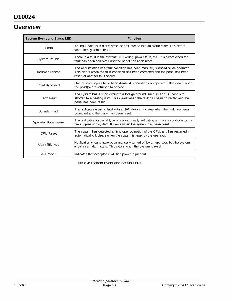
The middle display is a row of LEDs that indicate the type of system event and status. See Table 3 for the functions ofthe system event and status LEDs.
The lower display area is the zone/area display that indicates the location and type (alarm or trouble) of event. TheD10024 can have up to 80 zones.
Alphanumeric Display
Control Keys
61 62 63 64 65 66 67 68
41 42 43 44
21
1
22 23 24
2 3 4
45 46 47 48
25
5
26 27 28
6 7 8
77
57
37
69 70 71 72 73 74 75 76
49 50 51 52
29 30 31 32
9 10 11 12
53 54 55 56
33 34 35
13 14 15
36
16
78 79 80
58 59 60
38 39
17 18 19
40
20
ENTER YESNO
ALARMTROUBLE
TROUBLEALARM
ALARMTROUBLE
TROUBLEALARM
ALARM SystemTrouble
TroubleSilenced
PointBypassed
EarthFault
SounderFault
SprinklerSupervisory
CPUReset
AlarmSilenced
ACPower
SystemReset
TroubleSilence
AlarmSilence
ManualAlarm
LettersNumbers
Keyword
SHIFT AN
BO
CP
DQ
ER
FS
GT
HU
IV
JW
KX
LY
MZ
0 1 2 3 4 5 6 7 8 9 CHANGE
AlphanumericKeys
Program/Interactive
Keys
LED Display
Zone/AreaDisplay
Figure 2: D10024 Controls and Displays
Overview
D10024
D10024 Operator’s Guide46521C Page 10 Copyright © 2001 Radionics
System Event and Status LED Function
AlarmAn input point is in alarm state, or has latched into an alarm state. This clearswhen the system is reset.
System TroubleThere is a fault in the system: SLC wiring, power fault, etc. This clears when thefault has been corrected and the panel has been reset.
Trouble SilencedThe annunciation of a fault condition has been manually silenced by an operator.This clears when the fault condition has been corrected and the panel has beenreset, or another fault occurs.
Point BypassedOne or more inputs have been disabled manually by an operator. This clears whenthe point(s) are returned to service.
Earth FaultThe system has a short circuit to a foreign ground, such as an SLC conductorshorted to a heating duct. This clears when the fault has been corrected and thepanel has been reset.
Sounder FaultThis indicates a wiring fault witn a NAC device. It clears when the fault has beencorrected and the panel has been reset.
Sprinkler SupervisoryThis indicates a special type of alarm, usually indicating an unsafe condition with afire suppression system. It clears when the system has been reset.
CPU ResetThe system has detected an improper operation of the CPU, and has restarted itautomatically. It clears when the system is reset by the operator.
Alarm SilencedNotification circuits have been manually turned off by an operator, but the systemis still in an alarm state. This clears when the system is reset.
AC Power Indicates that acceptable AC line power is present.
Table 3: System Event and Status LEDs
Overview

D10024
D10024 Operator’s GuideCopyright © 2001 Radionics Page 11 46521C
3.0 Control Level 1 (Display Functions)At Control Level 1, the control keys are disabled and the control panel functions only as an annunciator. Pressing anyof the control keys will result in a series of interactive messages on the alphanumeric display that end in a prompt for aControl Level 2 passcode.
The following subsections explain the features options of Control Level 1.
3.1 Power ConditionsWhen the system is being powered by 120 VAC, the green AC Power LED in the lower right of the LED display will belit. The normal alphanumeric display will alternate between a time and date message and a system status message.
If the 120 VAC power source is interrupted, the AC Power LED will flash, the panel buzzer will sound and the SystemTrouble and Earth Fault LEDs will light. The alphanumeric display will no longer be illuminated, and the display will showan “AC Fail” message and provide information about the failure, the status of the standby batteries and the telephonenumber for service. Pressing the [Trouble Silence] key will silence the panel buzzer.
3.2 Trouble ConditionsIf a device fails to respond, is disabled, the response is not within the normal parameters, or the system detects a fault,the amber System Trouble or Fault LEDs will light. The amber Trouble LED in the Zone/Area section of the panel willlight to indicate the location, the panel’s buzzer will sound and the alphanumeric display will provide detailed information.If more than one fault is present, the display will automatically scroll through the first four faults.
3.3 Alarm ConditionsThe two red alarm LEDs at the left of the display flash to indicate the system has detected a fire condition. The Zone/Area alarm LED(s) lights, indicating the alarm location(s) and the alphanumeric display provides detailed information.If more than one fire is present, the display will automatically scroll through the first four alarms.
Control Level 1

D10024
D10024 Operator’s Guide46521C Page 12 Copyright © 2001 Radionics
Notes:
Control Level 1

D10024
D10024 Operator’s GuideCopyright © 2001 Radionics Page 13 46521C
4.0 Control Level 2 (Controller Functions)At Control Level 2, the control panel functions as a Controller (see Section 2.2 “Control Level Distinction”). To enablethe control keys (to enter Control Level 2), press the [Shift] key. The alphanumeric display shows the following prompt:
[Panel ACTIVE control keys INHIBITED] [1]Do you want to enable the control keys?
Figure 3: Control Level 2, Entry Menu 1
Press the [Yes] key to enable the control keys.
The display shows Control Level 2, Entry Menu 2.
[Panel ACTIVE control keys INHIBITED] [1]Please enter password
Figure 4: Control Level 2, Entry Menu 2
Enter the four digit Control Level 2 passcode.
The display shows the Main Menu.
[ACTIVE] 1) Commission 2) Test 3) Time [1]4) Enable 5) Disable 6) Print 7) View
Figure 5: Main Menu
The D10024 has ten Control Level 2 passcodes available that are assigned from Control Level 3 (Programmer’s Level).Press the [4] key on the alphanumeric key row. The display shows the Enable Menu.
ENABLE: 1) Zone 2) Input 3) Keys4) Day Mode 5) Outputs
Figure 6: Enable Menu
Press the [3] key on the alphanumeric row. The display returns to the Main Menu (see Figure 5). The control keys arenow enabled for the amount of time programmed into the panel. At the end of the programmed time period, the panelwill automatically inhibit the control keys.
The following subsections describe specific conditions that may arise while the D10024 is operating, and explain howto interface with the panel to resolve these conditions.
4.1 Power ConditionsThe D10024 supervises its AC power supply and standby batteries.
4.1.1 Power Failure Signal
If the 120 VAC power source is interrupted, the AC Power LED will flash, the panel buzzer will sound and the amberSystem Trouble and Earth Fault LEDs will light. The alphanumeric display will no longer be illuminated and it will showan “AC Fail” message and provide information about the failure and the status of the standby batteries. If the standbybatteries fail, the AC Power LED will go out.
4.1.2 Power Failure Signal Response
To silence the panel buzzer, enter Control Level 2 by pressing the [Shift] key, enable the control keys and press the[Trouble Silence] key. The amber Trouble Silence LED will light.
When the 120 VAC power is restored, the green AC Power LED will stop flashing, but will remain lit, and the SystemTrouble and Earth Fault LEDs will go out. The amber CPU Reset LED lights while the system resets itself and goes outwhen the reset is complete. The alphanumeric display returns to normal.
Control Level 2

D10024
D10024 Operator’s Guide46521C Page 14 Copyright © 2001 Radionics
4.2 Trouble ConditionsThe system responds to other-than-normal conditions that are not caused by alarms by sounding the internal buzzerand initiating a Trouble Condition.
4.2.1 Trouble Signals
If a device fails to respond, is disabled, the response is not within the normal parameters, or the system detects a fault,the amber System Trouble or Fault LED will light. In addition, the amber Trouble LED in the Zone/Area section of thepanel will light to indicate the location, the panel’s internal buzzer will sound and the alphanumeric display will providedetailed information.
4.2.2 Trouble Signal Response
To acknowledge a trouble signal, enter Control Level Two by pressing the [Shift] key, enable the control keys and pressthe [Trouble Silence] key to mute the internal buzzer (under certain circumstances, the system may override themute). The amber Trouble Silenced LED will light to indicate that condition. The system will not allow a reset until theproblem is corrected. If necessary, the system allows disabling of individual devices and zones (see Section 4.5.3“Enable/Disable Functions”). After correcting the problem, press the [System Reset] key. The amber Trouble SilencedLED will go out and the alphanumeric display will return to normal.
4.3 Alarm ConditionsThe D10024 will signal an alarm if it detects an alarm condition or a fire drill test.
4.3.1 Alarm Signals
If the D10024 initiates an alarm condition, the red Alarm LEDs at the left of the LED display flash to indicate the systemhas detected a fire condition and has activated its Notification Appliance Circuit (NAC) devices (horns, strobes, etc.),the internal buzzer sounds, Zone/Area Alarm LED(s) light indicating the event location and the alphanumeric displayprovides detailed information.
To test the alarm system, enter Control Level 2 by pressing the [Shift] key, enable the control keys and press the [FireDrill] key. The panel will activate all system NAC devices. The red Alarm LEDs at the left of the LED display will flashand the internal buzzer will sound. The alphanumeric display will show a “Fire Test” message.
4.3.2 Alarm Signal Response
Press the [Alarm Silence] key to turn off all external NAC devices. The Alarm Silenced LED will light. Pressing the[Alarm Silence] key again turns on all external NAC devices.
Press the [Trouble Silence] key to turn the panel buzzer off. The amber Trouble Silenced LED will light.
Press the [System Reset] key to reset the system. The Alarm and Trouble Silenced LEDs will go out and the alphanumericdisplay will return to normal.
Note: The D10024 can be reset at any time, however if a device is still in alarm when the D10024 is reset, the D10024 will goback into an alarm condition.
To return the system to Control Level 1, press the [Shift] key and select 5) Disable from the alphanumeric display.
Then select 3) Keys from the display. The panel will briefly display the Control Level 2 Entry Menu 2 and then revert tothe normal display (alternating between a time and date display and a system status message).
Press the [Fire Drill] key to verify that the keys are disabled. The display will prompt “Do you want to enable the controlkeys?”
Press the [No] key. The display will return to normal.
Control Level 2

D10024
D10024 Operator’s GuideCopyright © 2001 Radionics Page 15 46521C
4.4 System Operation (Main Menu Options)Pressing the [Shift] key from the normal display will open the Main Menu on the alphanumeric display. The first option,1) Commission, is not available to Control Level 2 Operators. See the Analog Fire Alarm Control Panels ProgrammingGuide (P/N: 38789) for commissioning and programming information. The other options on the Main Menu permit testsand the setting, enabling and disabling of various system functions.
[ACTIVE] 1) Commission 2) Test 3) Time [1]4) Enable 5) Disable 6) Print 7) View
Figure 7: Main Menu
4.4.1 System Tests
Select 2) Test from the Main Menu to open the Test Menu. This menu allows the Control Level 2 user to test thefollowing:
• The LEDs on the Front Panel Display
• The alphanumeric (liquid crystal) display
• Detection and alarm initiating devices connected to the polling circuit
• NAC and other alarm condition devices connected to the system
1) LEDs 2) LCD 3) Zones 4) Outputs
Figure 8: Test Menu
Note: If no action is taken, the display reverts to the normal display after one minute.
Note: The fourth option in the Test Menu, 4) Outputs, is not available to Control Level 2 Operators.
4.4.1.1 LEDs Test
Select 1) LEDs by pressing the [1] key. The panel will flash all LEDs on the LED display and step through all the alarmand trouble LEDs in the Zone/Area display. On completion of the test, the display will report the results of the test andautomatically revert back to the normal menu after one minute. To interrupt and end the test, press the [No] key.
4.4.1.2 LCD Test
Select 2) LCD from the Main Menu by pressing the [2] key. The alphanumeric display will flash all characters in allspaces on the alphanumeric display and return to the Main Menu.
4.4.1.3 Zones Test
Select 3) Zones by pressing the [3] key. The Zones Test allows the operator to test devices on the polling circuit(s) andperipheral device circuit(s) without having to reset the panel after each device is tested.
Note: If no action is taken within one minute, the display reverts to the normal display. Press the [>] key to restore the Testdisplay.
The panel displays Zone Test Menu 1.
Ring bells?
Figure 9: Zone Test Menu 1
Press the [Yes] key to activate the NAC devices briefly as each device is tested, or press the [No] key to bypass theindicator test. The panel then displays Zone Test Menu 2.
Control Level 2

D10024
D10024 Operator’s Guide46521C Page 16 Copyright © 2001 Radionics
Test from zone?(key in number, then press “Enter’)
Figure 10: Zone Test Menu 2
Enter the number of the first zone to be tested and press [Enter]. The panel will then display Zone Test Menu 3. If, forexample, “12” is keyed in, the display would show:
Test from 12 to zone ?(key in number, then press “Enter”)
Figure 11: Zone Test Menu 3
If “15” is keyed in, the panel would display the Walk Test Mode as follows:
Test from 12 to Zone 15----------W----------
Figure 12: Zone Test Menu 4
The moving “W” across the lower line alternates with a “Press NO to EXIT” message.
Note: Once the display indicates the panel is in the Walk Test Mode, the display will not revert to normal. The panel willterminate the test and sound the panel buzzer if there is no activity for a 20 minute period.
The operator may test devices within the zone parameters shown on the display. The panel responds to each test by:
• Displaying an activation message on the alphanumeric display
• Entering the activation in the event log
• Lighting the alarm LED in the Zone/Area display
• Sounding the panel buzzer
• Lighting the LED at the device in alarm
After a few seconds, the panel will automatically reset and turn off the device LED. The panel allows up to one minutefor smoke devices to clear. The operator may then test the next device.
If the panel detects an alarm condition in a zone other than those being tested, all NAC devices and relays will activateas programmed. NAC devices will continue to operate until silenced from the panel.
Terminate the Walk Test by pressing the [No] key. The display will return to the Main Menu (see Figure 13).
Note: The fourth option in the Test Menu, 4) Outputs, is not available to Control Level 2 Operators.
[ACTIVE] 1) Commission 2) Test 3) Time [1]4) Enable 5) Disable 6) Print 7) View
Figure 13: Main Menu
Control Level 2

D10024
D10024 Operator’s GuideCopyright © 2001 Radionics Page 17 46521C
4.4.2 Time Setting
Select 3) Time from the Main Menu to change the time displayed on the D10024.
4.4.3 Enable/Disable Functions
Main Menu option four, 4) Enable, opens the Enable Menu. Main Menu option five, 5) Disable, opens the Disable Menu.
ENABLE: 1) Zone 2) Input 3) Keys 4) Day Mode 5) Outputs
DISABLE: 1) Zone 2) Input 3) Keys 4) Day Mode 5) Outputs
Figure 14: Enable/Disable Menus
The content of the Enable and Disable menus is identical, allowing the operator to enable or disable zones, individualdevices (input), panel keys, day modes and outputs (relays).
Note: NAC devices such as bells, horns and strobes cannot be enabled or disabled from Control Level 2.
4.4.3.1 Enable/Disable by Zone
To enable or disable input signals from devices by zone, select the first option, 1) Zone, from the Enable or DisableMenu.
The display will prompt for the zone number. Key in the zone number and press the [Enter] key.
The display will repeat the zone number and ask “OK?”. Press the [Yes] key to confirm. The panel will then enable ordisable all the input devices in the selected zone.
Note: Any disabled circuit-driven device or relay on a circuit will still operate on output as programmed. Only the input signalwill be disabled. However, manual pull stations (alarm boxes) within the zone are not disabled.
When a device is disabled, the amber Point Bypassed LED on the LED display will light. The amber Trouble LED in thecorresponding zone of the Zone/Area display will also light, and the panel will display a disable message on thealphanumeric display.
4.4.3.2 Enable/Disable Individual Detection Devices (Inputs)
To enable or disable input signals from individual detection devices, select 2) Input from the Enable/Disable Menu.
The display will prompt for the polling circuit (loop) number (1-5). Key in the circuit number and press [Enter].
The display will then prompt for the address of the device. Key in the address and press [Enter].
The display will then repeat the circuit number and address. Press the [Yes] key.
Note: Any disabled circuit-driven device or relay on a circuit will still operate on output as programmed. Only the input signalwill be disabled.
4.4.3.3 Enable/Disable Panel Keys
To enable panel keys, press any of the control keys except the [No] key, or press the [>] key.
The panel will prompt “Do you want to enable the control keys?”. Press the [Yes] key.
The panel then prompts for the Control Level 2 passcode. Key in the appropriate passcode.
The panel keys will be enabled for the programmed period of time. The display reverts to the Main Menu (see Figure13). After one minute, the display reverts to the normal display. Pressing the [System Reset] key will also return thedisplay to the normal display.
To disable the panel keys, select 3) Keys from the Disable Menu. The display indicates that the panel keys are inhibitedand then returns to the normal display. Disabling the panel keys returns the D10024 to Control Level 1.
Control Level 2

D10024
D10024 Operator’s Guide46521C Page 18 Copyright © 2001 Radionics
4.4.3.4 Enable/Disable Delayed Day Mode
The Delayed Day Mode is configured from Control Level 3. This mode causes the panel to respond to high sensorsignals by sounding the panel buzzer and displaying a warning message at the alphanumeric display. The panel delaysalarm activation for a programmed period. Configuration parameters allow variations in time of day and zones affected.The Control Level 2 operator may enable or disable the Delayed Day Mode through the Enable or Disable Menu.
To enable the Delayed Day Mode, select 4) Day Modes from the Enable Menu.
The display will prompt for the programmed number of days. To accept as prompted, press the [Yes] key.
To change from the prompted number of days, press the [Change] key, enter the desired number of days and press the[Enter] key.
Enter 0 days to disable the Delayed Day Mode. Enter 200 days to permanently enable the Delayed Day Mode.
Note: If the Delayed Day Mode has not been programmed into the panel, pressing 4) Day Modes from the Enable or DisableMenu will return the alphanumeric display to the Main Menu.
4.4.3.5 Enable/Disable Relays
Press [5] for Disable from the Main Menu to disable relays during testing. The panel will then display the Disable Menu.Press [5] for Outputs. The display shows the following:
1) Sounders 2) Relays ENABLED ENABLED
Figure 15: Outputs Menu
Note: NAC devices such as bells, horns and strobes, all of which are sounders, cannot be enabled or disabled from ControlLevel 2.
Select 2) Relays. The panel buzzer will sound, the System Trouble LED will light and the alphanumeric display messageindicates that the relays are disabled.
Press the [Trouble Silence] key to silence the buzzer. The Trouble Silenced LED will light.
Note: Any disabled outputs must be enabled before the system can be reset.
To enable the outputs, press the [No] key to revert to the Main Menu.
[ACTIVE] 1) Commission 2) Test 3) Time [1]4) Enable 5) Disable 6) Print 7) View
Figure 16: Main Menu
Press the [4] key to enter the Enable Menu.
Press [5] for Outputs.
Press [5] for Relays. The system will reset and the Trouble Silenced LED will go out.
Press the [No] key to return to the Main Menu.
Control Level 2

D10024
D10024 Operator’s GuideCopyright © 2001 Radionics Page 19 46521C
4.4.4 Print Functions
To enter the Print Menu, select 6) Print from the Main Menu. This menu controls the operation of the front panel printer(if installed).
PRINT: 1) Devices 2) Events 5) Disabled 3) Mode 4) Setup
Figure 17: Print Menu
4.4.4.1 Print Devices
This option allows the operator to print out the current state and the text assigned to all devices on a polling circuit(loop).
4.4.4.2 Print Events (Event Log)
This option allows the operator to print out the contents of the event log.
4.4.4.3 Print Mode
This option allows the operator to toggle between manual and automatic printing. The current selection is shown on thePrint Menu display. In Manual Mode, the printer prints only on demand. In Automatic Mode, the printer automaticallyprints events as they occur.
4.4.4.4 Print Direction
This option allows the operator to change print direction on panel-mounted printers.
4.4.4.5 Print Disabled
This option allows the operator to print the location of all disabled devices.
4.4.5 View Functions
Select 7) View from the Main Menu to enter the View Menu. This menu displays information about the selected optionon the alphanumeric display. After viewing an option, press the [No] key to return to the View Menu. Press the [No] keyagain to return to the Main Menu.
VIEW: 1) Device 2) Log 3) Faults4) Outputs 5) Disablements 6) Sys Events
Figure 18: View Menu
4.4.5.1 View Devices
This option allows the operator to view the current state and text of any device on a circuit.
Select 1) Devices from the View Menu.
The display will prompt for the loop (circuit) number. Key in the circuit number and press [Enter].
The display will then prompt for the address. Key in the address and press [Enter].
4.4.5.2 View Event Log
This option allows the operator to view the Event Log.
Select 2) Log from the View Menu and press [Enter].
The display prompts a beginning entry number. The default is the latest entry. Press [Yes] to accept the prompt.
Press [No] to select another entry. Use the [<] [>] keys to scroll through the log.
Exit this menu by pressing the [No] key.
4.4.5.3 View Faults
This option displays the panel fault status. This is the same display as the normal alphanumeric display without thelogo. The operator may scroll through all the faults using the [<] [>] keys.
Exit this menu by pressing the [No] key.
Control Level 2

D10024
D10024 Operator’s Guide46521C Page 20 Copyright © 2001 Radionics
Control Level 24.4.5.4 View Outputs
This option displays information on the outputs.
Using the Alarm Silence Key forces all NAC devices to an OFF condition.
4.4.5.5 View Disablements
This option displays information on disabled devices. Select 1) Zones to view disabled devices by zone. Select 2)Inputs to view disabled input devices.
4.4.5.6 View System Events
This option displays information on system events. Use the [<] [>] keys to scroll through the events.

D10024
D10024 Operator’s GuideCopyright © 2001 Radionics Page 21 46521C
Control Level 3
5.0 Control Level 3 (Programmer Functions)Note: Commission, configure, networking and certain disable options are not available to Control Level 2 operators. These
options are reserved for Control Level 3 operators. See the Analog Fire Alarm Control Panels Programming Guide(P/N: 46482) for complete information on commissioning and programming the D10024 Analog FACP.
5.1 Enable/Disable Sounders (NAC Devices)All sounders (NAC devices such as horns, bells, strobes, etc.) and relays can be enabled or disabled from the controlpanel during testing. Disabling NAC devices requires a Control Level 3 passcode. No passcode is required to enableNAC devices.
From the Main Menu, press [5] for Disable. The Disable Menu is displayed.
Press [5] for Outputs. The display shows:
1) Sounders 2) Relays ENABLED ENABLED
Figure 19: Outputs Submenu
Press 1) Sounders. The display prompts for the Control Level 3 passcode. Enter the passcode. The panel buzzer willsound, the System Trouble LED will light and the display message will indicate that the output is disabled.
Press the [Trouble Silence] key to silence the buzzer. The Trouble Silenced LED will light.
The disabled output must be enabled before the system can be reset.
To enable the outputs, press the [No] key to revert to the Main Menu.
Press the [4] key to enter the Enable Menu.
Press [5] for Outputs.
Press [1] for Sounders. The system will reset and the Trouble Silenced LEDs will go out.

D10024
D10024 Operator’s Guide46521C Page 22 Copyright © 2001 Radionics
Control Level 3
Notes:

D10024
D10024 Operator’s GuideCopyright © 2001 Radionics Page 23 46521C
Index
IndexA
Alarm Signal Response .............................................. 14Alarm Signals ............................................................... 14Alphanumeric and Program/Interactive Key Functions 9
C
ConditionsAlarm Conditions ..................................................... 11, 14Power Conditions .................................................... 11, 13Trouble Conditions .................................................. 11, 14
Control Key Functions ................................................. 8Control Level 1 (Display Functions) ........................... 11Control Level 2 (Controller Functions) ....................... 13Control Level 3 (Programmer Functions) ................... 21Control Level Distinction
Control Level 1 (Display Level) .............................. 8Control Level 2 (Controller Level) .......................... 8Control Level 3 (Programmer’s Level) ................... 8
Controls and Displays ................................................. 8
M
Main Menu OptionsEnable/Disable Functions
Enable/Disable by Zone ...................................... 17Enable/Disable Delayed Day Mode ................... 18Enable/Disable Individual Detection Devices ...... 17Enable/Disable Panel Keys ................................ 17Enable/Disable Relays ........................................ 18
Print FunctionsPrint Direction ...................................................... 19
Print FunctionsPrint Devices ....................................................... 19Print Disabled ...................................................... 19Print Events (Event Log) ..................................... 19Print Mode ........................................................... 19
TestLEDs Test ............................................................. 15
TestsLCD Test .............................................................. 15System Tests ....................................................... 15Zones Test ........................................................... 15
Time Setting ............................................................. 17View Functions
View Devices ....................................................... 19View Disablements .............................................. 20View Event Log .................................................... 19View Faults .......................................................... 19View Outputs ....................................................... 20View System Events ........................................... 20
MenusControl Level 2, Entry Menu 1 ................................ 13Control Level 2, Entry Menu 2 ................................ 13Enable Menu ............................................................ 13Enable/Disable Menus ............................................ 17Main Menu ..........................................13, 15, 16, 18Outputs Menu .......................................................... 18Print Menu ................................................................ 19Test Menu ................................................................. 15View Menu ............................................................... 19Zone Test Menu 1 .................................................... 15Zone Test Menu 2 .................................................... 16Zone Test Menu 3 .................................................... 16Zone Test Menu 4 .................................................... 16
N
NoticesFCC Notice .............................................................. 5General Notices ....................................................... 5UL/NFPA Notice ...................................................... 5
O
Overview ...................................................................... 7
P
Passcodes ................................................................... 8Power Failure Signal ................................................... 13Power Failure Signal Response ................................. 13
S
System Overview ......................................................... 7
T
Trouble Signal Response ............................................ 14Trouble Signals ............................................................ 14

© 2001 Radionics, a division of Detection Systems, Inc. 46521C 8/01PO Box 80012, Salinas, CA 93912-0012 USA Operator’s Guide D10024Customer Service: (800) 538-5807 Page 24 of 24