D t · SUPPLEMENTARY NOTES 19. KEY WORDS (Continue on reverse aide if necessary end identify by...
49
A-AII' .933 ARINC RESEARCH CORP ANNAPOLIS MD F/ 1/3 RELIABILITY, AVAILABILITY, MAINTAINABILITY DATA TRACKING PLAN I--ECCU) IJUN 82 S JOES, Rt FOOTE, H4 RISER OAABITTB6A-6606 UNCLASSIFIED 1599-01-A-2711 ML
Transcript of D t · SUPPLEMENTARY NOTES 19. KEY WORDS (Continue on reverse aide if necessary end identify by...
A-AII' .933 ARINC RESEARCH CORP ANNAPOLIS MD F/ 1/3RELIABILITY, AVAILABILITY, MAINTAINABILITY DATA TRACKING PLAN I--ECCU)
IJUN 82 S JOES, Rt FOOTE, H4 RISER OAABITTB6A-6606UNCLASSIFIED 1599-01-A-2711 ML
ARIEC Research Phhllsatiemo 159-01-2-2711
RELIABILITY, AVAILABILITY, MAI NTAINABILITYDATA TRACKING PLAN
IMPROVED GUARDRAIL V
I Jun. 1982
-~ Prepared forPRODUCT MANAGER
SPECIAL ELECTRONIC MISSION AIRCRAFT D tST. LOUIS, MISSOURI E EL E C f'
under Contract OAAB7-78-A-6606-2V14 AU6 1 23
A 13RXX C RESEARCH CORPORATION
pp D-191ibiIon Unjjw,!lt
I 82 08 06 005
UnclassifipdSECURITY CLASSIFICATION OF THIS PAGE (IfRen Date'Entered)
REPORT DOCUMENTATION PAGE READ INSTRUCTIONS
BEFORE COMPLETING FORMI. REPORT NUMBER 2. GOVT ACCESSION N 3. RECIPIENT'S CATALOG NUMBER
1599-01-2-27 11 7'4. TITLE (end Subtitle) S. TYPE OF REPORT & PERIOD COVERED
Reliability, Availability, Maintainability DataTracking Plan Improved Guardrail V
S. PERFORMING ORG. REPORT NUMBER
1599-01-2-27117. AUTHOR(&) S. CONTRACT OR GRANT NUMBER(a)
S. JonesR. FooteH. Riser
9. PERFORMING ORGANIZATION NAME AND ADDRESS 10. PROGRAM ELEMENT. PROJECT, TASKARINC Research Corp. AREA & WORK UNIT NUMBERS
2551 Riva RoadAnnapolis, Md. 21401
II. CONTROLLING OFFICE NAME AND ADDRESS 12. REPORT DATE
Product Manager June 1982Special Electronic Mission Aircraft 13. NUMBER OF PAGES
St. Louis, Missouri 50I4. MONITORING AGENCY NAME & ADDRESS(if different from Controlling Office) 15. SECURITY CLASS. (of this report)
Unclassi fiedISa. DECLASSIFICATION/DOWNGRAOING
SCHEDULE
16. DISTRIBUTION STATEMENT (of this Report)
Unlimited
17. DISTRIBUTION STATEMENT (of the abstract entered in Block 20. if different from Report)
IS. SUPPLEMENTARY NOTES
19. KEY WORDS (Continue on reverse aide if necessary end identify by block number)
ReliabilityAvailabilityMaintainabi I ityRAM
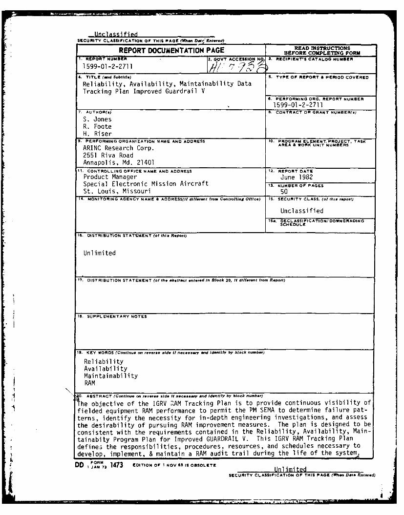
0. ABSTRACT (Continue on reverse side if necessry end identify by block number)The objective of the IGRV PZAM Tracking Plan is to provide continuous visibility of
fielded equipment RAM performance to permit the PM SEMA to determine failure pat-terns, identify the necessity for in-depth engineering investigations, and assessthe desirability of pursuing RAM improvement measures. The plan is designed to beconsistent with the requirements contained in the Reliability, Availability, Main-tainabity Program Plan for Improved GUARDRAIL V. This IGRV RAM Tracking Plandefines the responsibilities, procedures, resources, and schedules necessary todevelop, implement, & maintain a RAM audit trail during the life of the system.
DD IJN' 1473 EDITION OF I NOV 61 IS OBSOLETE. DD ,AN 7 UnlimitedSECURITY CLASSIFICATION OF THIS PAGE (When Data Entered)
I'

1
RELIABILITY, AVAILABILITY, MAINTAINABILITYDATA TRACKING PLAN
IMPROVED GUARDRAIL V
June 1982
-' Prepared for
Product ManagerSpecial Electronic Mission Aircraft
St. Louis, Missouri
under Contract DAAB07-78-A-6606-2V14
by,
S. JonesR. Foote 'kH. Riser
ARINC Research Corporationa Subsidiary of Aeronautical Radio, Inc.
2551 Riva Road ''-
Annapolis, Maryland 21401
Publication 1599-01-2-2711 , 0114
Copyright 0 1982
ARINC Research Corporation
This material may be reproduced by or for
the U. S. Government pursuant to the copy-
right license under DAR Clause 7-104.9(a)(May 1981).
rAccoBs
oNqT IS ORA&I.TIC T19
F.r
CONTENTS
Page
CHAPTER ONE: INTRODUCTION .. .......... ............ 1-1
1.1 Background ............ .............. 1-11.2 Objective. .. ........................ 1-11.3 Purpose.............................1-11.4 Scope..............................1-21.5 Implementation .. ............ ........... 1-21.6 Plan Organization. ........... ........... 1-3
CHAPTER TWO: IMPROVED GUARDRAIL V SYSTEM DESCRIPTION ......... 2-
2.1 System Background........................2-12.2 Operational Scope .. ..................... 2-12.3 Basic System Equipment Descriptions .. ............ 2-3
2.3.1 RC-12D Aircraft......................2-32.3.2 Remote Radio Receiver Set. .. .............. 2-42.3.3 Surveillance Information Processing Center .. ..... 2-52.3.4 Flight Line Test Set .. ................. 2-52.3.5 Other Equipment. .. ................... 2-5
2.4 Detailed Equipment List .. ................... 2-6
CHAPTER THREE: RAM TRACKING PARAMETERS .. ................ 3-1
3.1 Background............................3-13.2 Reliability.............................3-13.3 Availability .. ........... ............. 3-23.4 Maintainability. ........... ............ 3-2
3.4.1 Unit Level Maintainability .. .............. 3-33.4.2 Depot Level Maintainability. .. ............. 3-3
CHAPTER FOUR: RAM DATA COLLECTION PROCESS ................. 4-1
4.1 Overview .. .......... ................ 4-14.2 Data Sources .. ........... ............. 4-14.3 Data Collection. ............ ........... 4-2
4.3.1 Free-Flow Data Collection. .. ............. 4-3
4.3.1.1 Detailed Data Flow. .. ............ 4-34.3.1.2 In-House System Advantages. .. ........ 4-5
4.3.2 Semicontrolled Data Collection .. ........... 4-5
4.4 Data Storage .. ............ ............ 4-6
v
CONTEN IS (continued)
Page
CHAPTER FIVE: RAM DATA ANALYSIS. .. ................... 5-1
5.1 Overview .............. ............. 5-15.2 Technical Report Requirements .. ................ 5-1
5.2.1 Reliability Report .. .................. 5-25.2.2 Availability Report. .. ................. 5-25.2.3 Maintainability Report .. ................ 5-2
5.3 Technical Report Generation .. ................. 5-25.4 Report Graphics. ............... ........ 5-25.5 Report Use .. ............. ............ 5-3
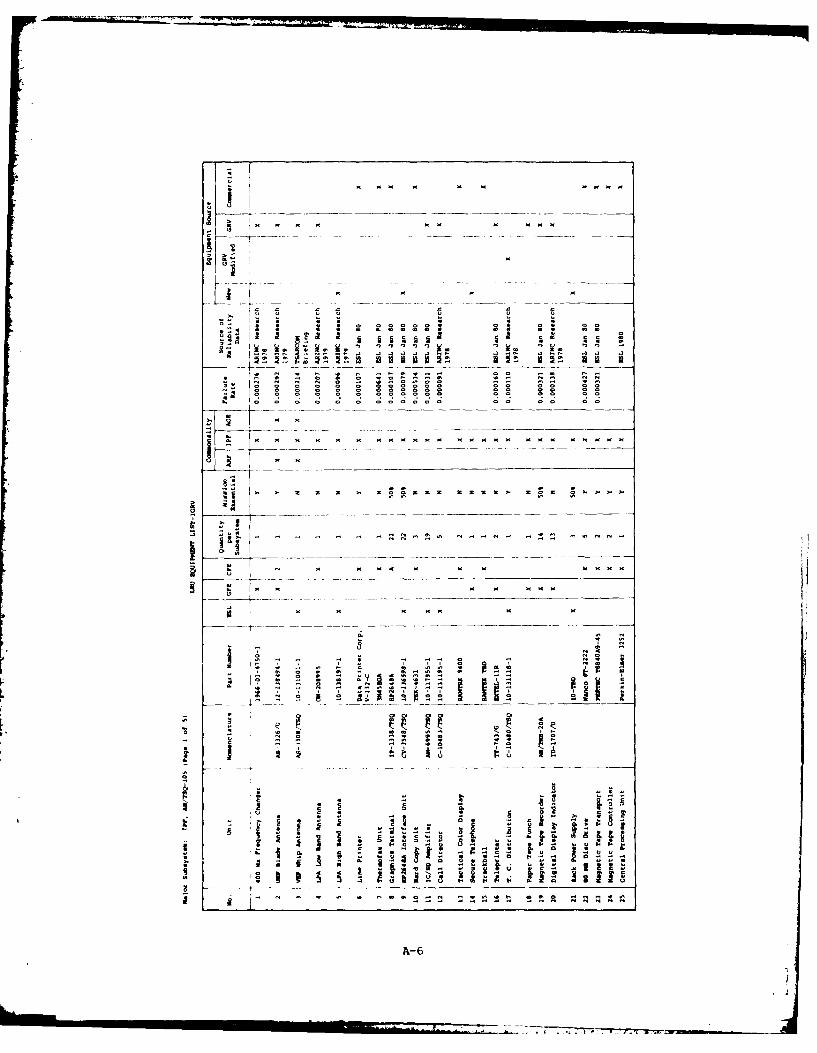
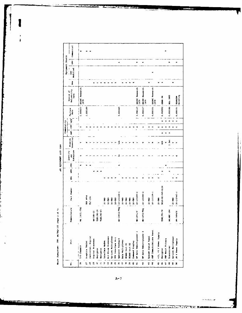
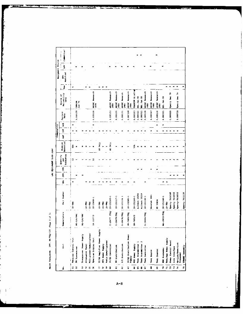
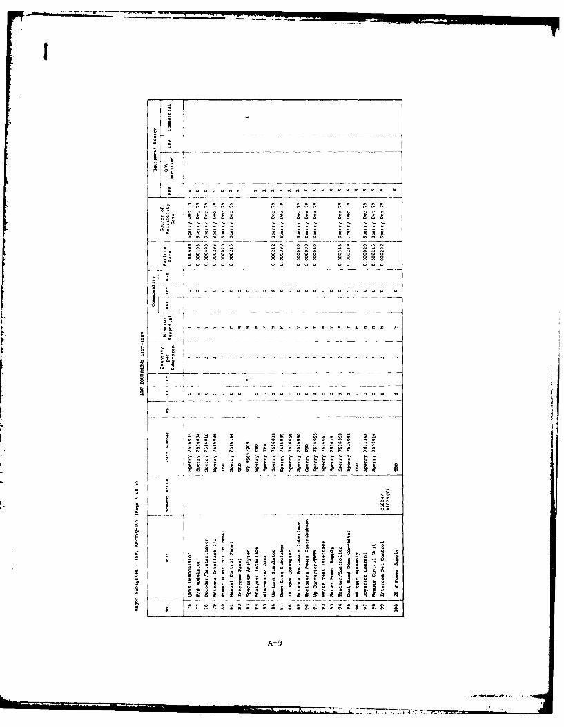
ANNEX A: LRU Lists for Major Subsystems of Improved GUARDRAIL V . A-1
ANNEX B: IGRV Points of Contact. .. .................. B-1
ANNEX C: Partial List of Standards, Directives, andOther Documents Pertaining to Reliability,Availability, and Maintainability. ............... C-1
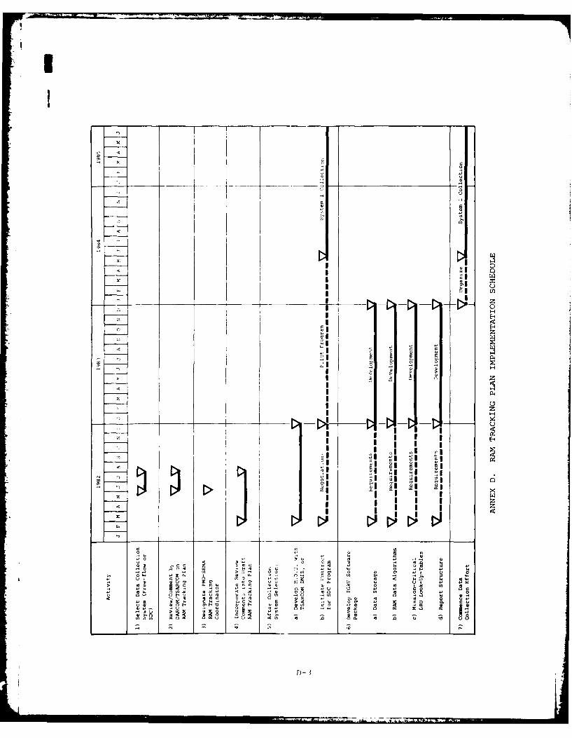
ANNEX D: RAM Tracking Plan Implementation Schedule. .......... D-1
ANNEX E: Description of DA Forms. .................... E-1
vi
?I
IT
CHAPTER ONE
INTRODUCTION
1.1 BACKGROUND
The Product Manager, Special Electronic Mission Aircraft (PM SEMA), todayhas cognizance over three GUARDRAIL V (GR-V) systems operating in the field. Areview of the reliability, availability, and maintainability (RAM) informationavailable to PM SEMA related to the existing GR-V systems showed deficiencies
in the quantity and quality of data necessary to adequately descriue andevaluate RAM performance. The primary data presented to PM SEMA relate tooperational availability (full mission capable, partial mission capable, andnot mission capable) for the RU-21H airborne platform only. These data aretaken from DA Forms 1352, submitted monthly by each GR-V unit. Specificallylacking are RAM data relative to the other three major GR-V subsystems: theRemote Radio Receiving Set, AN/ARW-83, called the ARF; the Surveillance Infor-mation Processing Center, AN/TSQ-105, called the IPF; and the Flight Line TestSet, AN/ARM-163, called the AGE Van. This RAM Data Tracking Plan has beendeveloped to rectify that situation for the Improved GUARDRAIL V System (IGRV).
1.2 OBJECTIVE
The objective of the IGRV RAM Tracking Plan is to provide continuousvisibility of fielded equipment RAM performance to permit the PM SEMA todetermine failure patterns, identify the necessity for in-depth engineeringinvestigations, and assess the desirability of pursuing RAM improvement mea-sures. The plan is designed to be consistent with the requirements containedin the Reliability, Availability, Maintainability Program Plan for improvedGUARDRAIL V (Appendix A to the "RAM Program Plan for SEMA Systems,' datedFebruary 1981) and is specifically designed for the collection and analysis ofRAM data on fielded, operational IGRV systems.
1.3 PURPOSE
This IGRV RAM Tracking Plan defines the responsibilities, procedures,resources, and schedules necessary to develop, implement, and maintain a RAMaudit trail throughout the operational life of the system.
1-1

1.4 SCOPE
This document describes the PM SEMA RAM tracking plan for fielded opera-tional IGRV systems, which includes the Remote Radio Receiver Set, AN/ARW-83;the RC-12D aircraft; the Surveillance Information Processing Center, AN/TSQ-105; and the Flight Line Test Set, AN/ARM-163. Details specifying the IGRVsystem and subsystems to be tracked are contained in Chapter Two and Annex A ofthis document.
Certain IGRV subsystems and ancillary equipment fall under the respon-sibility and tracking of product managers other than PM SEMA. In order toavoid duplicate reporting procedures, those subsystems are excluded from thisplan. The specific subsystems and associated equipment that will not betracked include the aircraft survivability equipment (ASE), common powergenerator sets (100 kW, 60 Hz and 60 kW, 60 Hz), and common ground handlingequipment associated with the aircraft and IPFs. However, mission-criticalGovernment furnished equipment (GFE), such as wide-band data link, crypto-graphic equipment, and UHF transceivers, will be tracked (even though they fallunder the cognizance of other product managers).
The RC-12D aircraft, including its core avionics, antennas, and inertialnavigation system (INS), will be maintained by Beech Aircraft Service, Incor-porated (BASI), under a separate service contract. While the mission-criticalINS will be tracked under this plan, the RC-12D will be tracked only as anentire subsystem. RAM performance of RC-12D LRUs will fall under the respon-sibility of the BASI maintenance contract.
1.5 IMPLEMENTATION
This plan is designed for implementation in two phases. The initial phasewill involve the collection and analysis of organizational, direct support,and general support levels of RAM data maintained by the IGRV units. Theprimary purpose of this phase will be to provide RAM performance informationfor LRUs and their parent systems. Analysis of RAM data at this level willdetermine the need for selective implementation of the second phase.
SL The second phase of this plan would be implemented to provide intensiveanalysis of particular problem line replaceable units (LRUS) identified underthe phase-one tracking. It involves the collection and analysis of maintenance
data (to the removed-component level) from off-site maintenance facilities.Depending on the particular LRU being investigated, the off-site facilitiescould include Army, Air Force, and commercial general support and depot facil-ities. Collection of the requisite data necessitates individual data gather-ing agreements with each maintenance facility and may involve contractualfunding as dictated by various commercial vendors. In view of the complexitiesinvolved with implementing phase two, only phase one should be implementedinitially, and phase two should be used on a selective basis at the discretionof the PM SEMA.
1-2
I.
The schedule for implementation of this plan is provided in Annex D. Theplan can be tested on existing GR-V systems to evaluate data accuracies andaddress problems before IGRV is fielded. The plan may be adopted for continu-ing use with fielded GR-V systems.
1.6 PLAN ORGANIZATION
This plan was prepared in accordance with AR 702-3 and Appendix A (datedFebruary 1982) to the "RAM Program Plan for SEMA Systems," dated 16 February1981. This plan consists of five chapters:
- Chapter One, Introduction
- Chapter Two, Improved GUARDRAIL V (IGRV) System Description
- Chapter Three, RAM Tracking Parameters
- Chapter Four, RAM Data Collection Process
- Chapter Five, RAM Data Analysis
Annex A of this plan contains a baseline of IGRV system equipments and adetailed breakout of the IGRV system LRUs by part/model number. Overall IGRVprogram and RAM management points of contact are identified in Annex B. AnnexC contains a partial list of applicable RAM standards, directives, and otherdocuments. Annex D provides an implementation schedule, and Annex E describesthe maintenance data collection forms.
1-3

CHAPTER TWO
IMPROVED GUARDRAIL V SYSTEM DESCRIPTION
2.1 SYSTEM BACKGROUND
IGRV is the latest in a series of U.S. Army airborne intelligence-collection systems dating back to 1974. Originally conceived as a QuickReaction Capability (QRC) effort by Electromagnetic System Laboratory (ESL),Inc., Sunnyvale, California, three different versions (GR-IIA, GR-IV, GR-V)have been fielded in Europe, the Far East, and in the continental United States(CONUS). There are currently three GR-V systems operating in the field,installed in RU-21H turboprop aircraft and using UHF encrypted command and datalinks. The other versions of the system have been dismantled. IGRV, a productimprovement to GR-V, will be developed according to system specificationssimilar to those of GR-V and use some identical or modified GR-V equipment.Two or more new systems will be built.
2.2 OPERATIONAL SCOPE
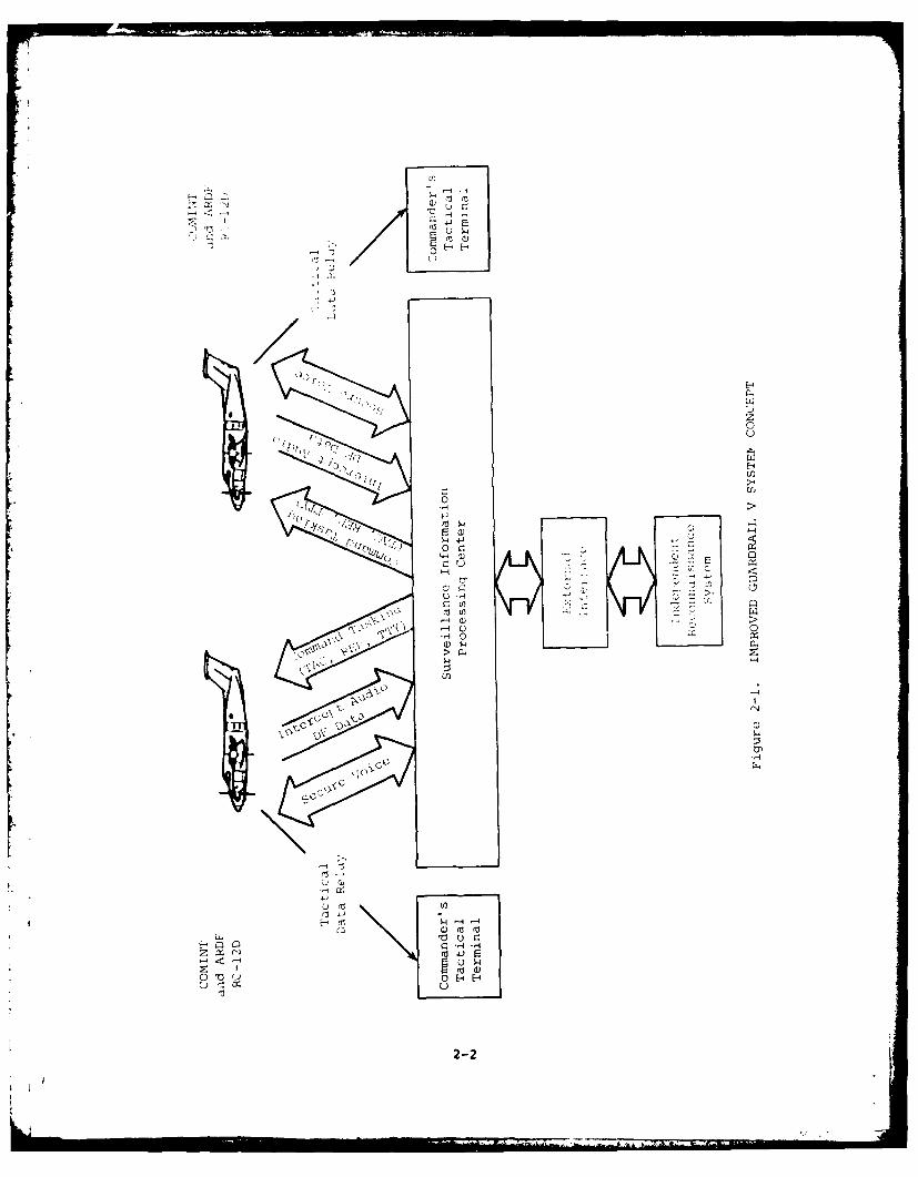
Improved GUARDRAIL V is an Army tactical communications intercept and
direction-finding system. The fielded system will consist of six RC-12D air-
craft per IGRV unit, each including an AN/ARW-83 (ARF); a ground processor,AN/TSQ-105 (IPF); a vehicle-mounted preflight test set, AN/ARM-163 (AGE Van);
and other associated test and maintenance equipment. GUARDRAIL is designatedas a corps intelligence asset, and is designed to provide a surveillance
capability over a corps front of approximately 150 kilometers. It is expectedto perform its mission day or night and in any location and climate where anyother corps aviation asset could normally operate.
Under the present operational concept, the Improved GUARDRAIL V Systemwould normally operate with two airborne Beech RC-12D mission aircraft withinterfaces with the ground processing facility through a Ku-band microwave
data link subsystem. It would communicate with the tactical commander viaencrypted UHF voice and teleprinter radio links; see Figure 2-1 for details of
the total system concept.
The IGRV will provide the following operational modes:
(A) General Search - the system will map the desired electromagnetic
environment to generate an electronic order of battle (EOB).
2-1
'-4
(1
e E-4
0 F0
J, (1 ->l
E-4 2'n ,
-2
I
(B) Programmed Search - IGRV will search for known emitters on unknownfrequencies.
(C) Directed Search - the system will search for known signals on pre-determined frequencies.
After collection and processing in the associated ground facility, thedata are then passed over encrypted UHF data links to the tactical commanderfor near real-time use. Although the time committed to each of the aboveoperational modes may vary according to the tactical situation, the overallconcept of system operation should not vary between peacetime and wartime;however, the number of missions would probably increase dramatically as indi-cations of the imminence of hostilities increase.
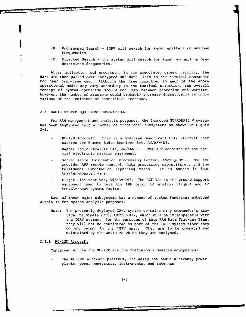
2.3 BASIC SYSTEM EQUIPMENT DESCRIPTIONS
For RAM management and analysis purposes, the Improved GUARDRAIL V systemhas been segmented into a number of functional subsystems as shown in Figure2-2.
RC-12D Aircraft. This is a modified Beechcraft C-12 aircraft thatcarries the Remote Radio Receiver Set, AN/ARW-83.
Remote Radio Receiver Set, AN/ARW-83. The ARF consists of the spe-cial electronic mission equipment.
Surveillance Information Processing Center, AN/TSQ-105. The IPFprovides ARF remote control, data processing capabilities, and in-telligence information reporting means. It is housed in fourtrailer-mounted vans.
Flight Line Test Set, AN/ARM-163. The AGE Van is the ground supportequipment used to test the ARF prior to mission flights and totroubleshoot system faults.
Each of these major subsystems has a number of system functions embeddedwithin it for system analysis purposes.
Note: The presently deployed GR-V system contains many commander's tac-tical terminals (CTT, AN/TSC-87), which will be interoperable withthe IGRV system. For the purposes of this RAM Data Tracking Plan,they will not be considered as part of the IGrN1 system since theydo not belong to the IGRV unit. They are to be operated andmaintained by the units to which they are assigned.
2.3.1 RC-12D Aircraft
Contained within the RC-12D are the following subsystem equipmen*s:
The RC-12D aircraft platform, including the basic airframe, power-
plants, power generators, instruments, and antennas
2-3
Aircraft ARF
Care ASE ES OtherAvionics Equipment GFE
AGE Van IPF
WBDL Mission Test [SLWBL7Equipment Equipment Equipment Equipment
Figure 2-2. IMPROVED GUARDRAIL V SYSTEM
The RC-12D aircraft's core avionics, including navigacion equipment(DME, VOR, TACAN, etc.), aircraft radios, autopilot/flight director,and navigation radar
Aircraft survivability equipment (ASE), including radar warning re-ceivers (AN/APR-39, AN/APR-44); laser, optical, and missile warningreceivers; M-130 chaff/flare dispenser; engine exhaust IR suppres-sors; low reflectance IR paint; and optional electronic counter-measures (ECM) equipment
A new improved inertial navigation system (INS - Carousel IV), in-cluding the navigation computer, inertial measurement unit, andassociated interface units
2.3.2 Remote Radio Receiver Set
Contained within the ARF are the following subsystem equipments:
Wide-band data link (WBDL), including traveling wave tube amplifier(TWTA), mux/demux equipment, microwave receivers, antenna control-lers, etc. This equipment is being developed by the U.S. Air Forceand will be Government furnished equipment for the IGRV system.
2-4
I
ESL special electronic mission equipment, including intercept re-ceivers, direction-finding receive -, digital processor, DF cont-roller, spectrum display converters, automatic signal search andrecognition equipment, and status display equipment.
Other GFE, including KY and KG series encryption equipment, receiverfilters, UHF link transceivers, and regenerative repeaters.
2.3.3 Surveillance Information Processing Center
Contained within the IPF are the following subsystem equipments:
ESL equipment, including command and control equipment, signal proc-essing equipment, display and analysis equipment, intercommunica-tion/signal data distribution equipment, built-in test and calibra-tion test equipment.
- Wide-band data link equipment, including Ku-band tracker trailersand associated microwave processing equipment, receivers, and base-band processing equipment.
- GFE, including KY/KG series encryptors/decryptors, voice tape re-corders, UHF/VHF and FM transceivers, master analog system timeequipment, and multichannel demodulators.
- Other contractor furnished equipment (CFE), including computer andperipheral equipment, display units, environment control equipment,radio frequency filters, test antennas, and trailer-mounted vans.
2.3.4 Flight Line Test Set
Contained within the AGE Van (a heavy duty step-van vehicle to providemobility) are the following subsystem equipments:
- Wide-band data link equipment
- Other GFE equipment such as UHF transceivers and KG/KY seriesencryptors/decryptors
- Microprocessor-controlled airborne mission test equipment
- Special display equipment for equipment preflight check-out
- A self-contained auxiliary power unit (APU)
2.3.5 Other Equipment
Several other items of equipment are supplied as part of the basic IGRVsystem, but will not be included ia the RAM data tracking system. They fallunder the cognizance of other PMs in various commands and data can be obtainedfrom the PMs as required. These equipments are as follows:
- Three equipment storage/repair vans
- Five 100 kW, 60 Hz generator sets
2-5
- Two 60 kW, 60 Hz generator sets
- One log periodic antenna test/calibration antenna
2.4 DETAILED EQUIPMENT LIST
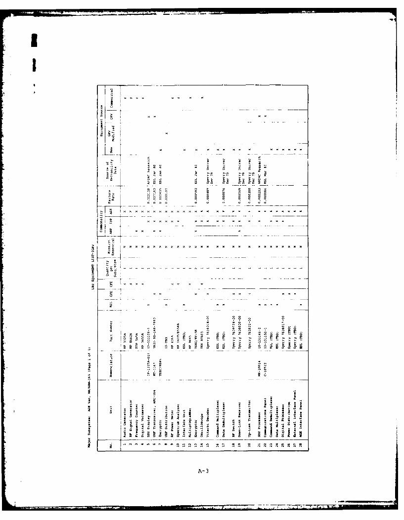
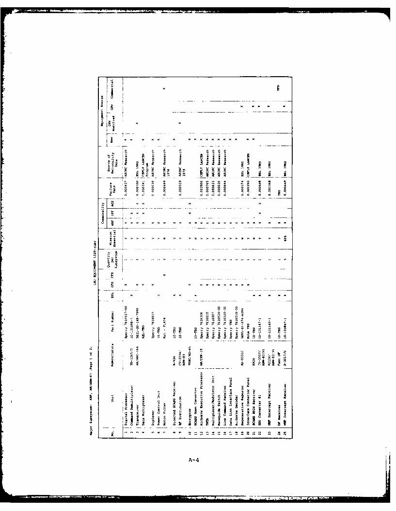
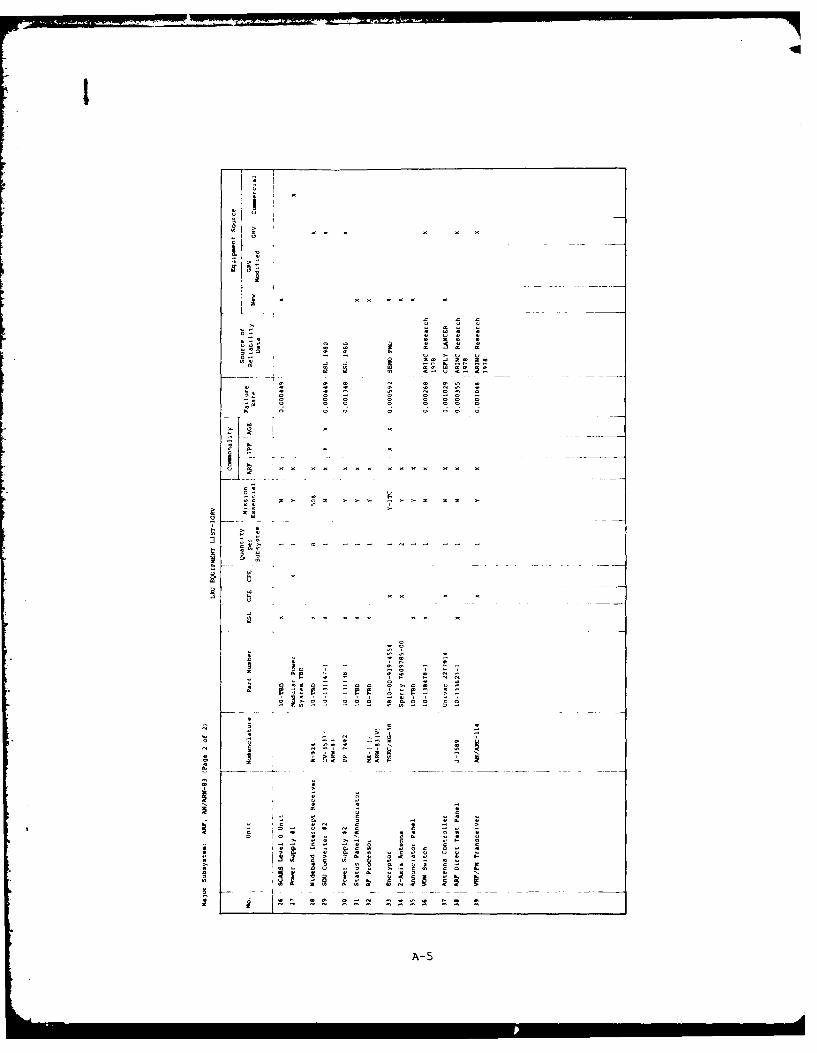
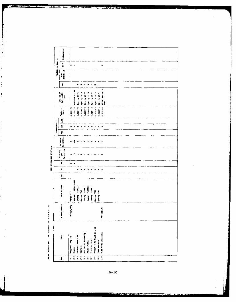
A detailed list of LRUs with part/model number for the ARF, IPF, and AGEVan is contained in Annex A. A list of LRUs for the RC-12D will be developedwhen the design is complete. Under present design criteria there are 39 LRUsin each ARF subsystem (six ARFs per IGRV unit), 110 LRUs in the IPF subsystem(one IPF per IGRV unit), and 28 LRUs in the AGE Van subsystem (one van per IGRVunit).
2-6
I
CHAPTER THREE
RAM TRACKING PARAMETERS
3.1 BACKGROUND
The selection of parameters to adequately portray the RAM characteristicsof the IGRV system must be tailored to accommodate the system/subsystem designand to minimize the impact on existing data collection procedures. The para-meters selected for this collection system are consistent with the above cri-teria. Since several types of RAM parameters are in common use today and therequirements and techniques for their computation vary, the following para-graphs define the specific parameters, data elements, and equations ofinterest.
3.2 RELIABILITY
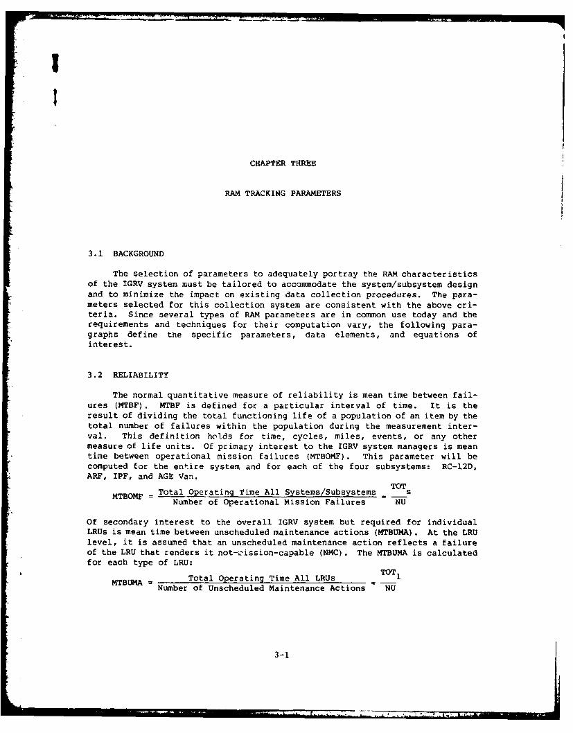
The normal quantitative measure of reliability is mean time between fail-ures (MTBF). MTBF is defined for a particular interval of time. It is theresult of dividing the total functioning life of a population of an item by thetotal number of failures within the population during the measurement inter-val. This definition holds for time, cycles, miles, events, or any othermeasure of life units. Of primary interest to the IGRV system managers is meantime between operational mission failures (MTBOMF). This parameter will becomputed for the entire system and for each of the four subsystems: RC-12D,ARF, IPF, and AGE Van.
TOT
MTBOMF = Total Operating Time All Systems/Subsystems = sNumber of Operational Mission Failures NU
Of secondary interest to the overall IGRV system but required for individualLRUs is mean time between unscheduled maintenance actions (MTBUMA). At the LRUlevel, it is assumed that an unscheduled maintenance action reflects a failureof the LRU that renders it not-i-ission-capable (NMC). The MTBUMA is calculatedfor each type of LRU:
MTBUMA Total Operating Time All LRUs TOT 1Number of Unscheduled Maintenance Actions NU
3-1
3.3 AVAILABILITY
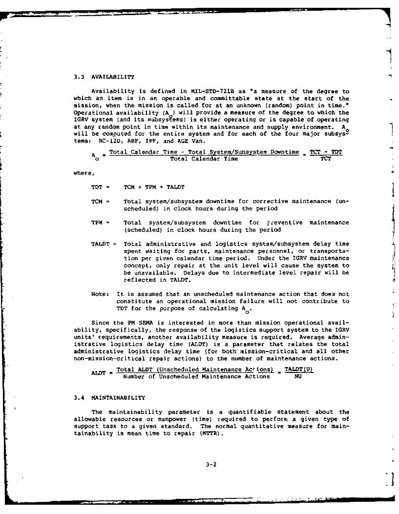
Availability is defined in MIL-STD-721B as "a measure of the degree towhich an item is in an operable and committable state at the start of the
mission, when the mission is called for at an unknown (random) point in time."
Operational availability (A ) will provide a measure of the degree to which theIGRV system (and its subsystems) is either operating or is capable of operating
at any random point in time within its maintenance and supply environment. Awill be computed for the entire system and for each of the four major subsys-tems: RC-12D, ARF, IPF, and AGE Van.
A = Total Calendar Time - Total System/Subsystem Downtime - TCT - TDTo Total Calendar Time TCT
where,
TDT = TCM + TPM + TALDT
TCM = Total system/subsystem downtime for corrective maintenance (un-scheduled) in clock hours during the period
TPM = Total system/subsystem downtime for -eeventive maintenance(scheduled) in clock hours during the period
TALDT = Total administrative and logistics system/subsystem delay timespent waiting for parts, maintenance personnel, or transporta-tion per given calendar time period. Under the IGRV maintenanceconcept, only repair at the unit level will cause the system tobe unavailable. Delays due to intermediate level repair will bereflected in TALDT.
Note: It is assumed that an unscheduled maintenance action that does notconstitute an operational mission failure will not contribute toTDT for the purpose of calculating A 0
0
Since the PM SEMA is interested in more than mission operational avail-
ability, specifically, the response of the logistics support system to the IGRVunits' requirements, another availability measure is required. Average admin-istrative logistics delay time (ALDT) is a parameter that relates the totaladministrative logistics delay time (for both mission-critical and all othernon-mission-critical repair actions) to the number of maintenance actions.
Total ALDT (Unscheduled Maintenance Actions) . TALDT(U)ALDT =Number of Unscheduled Maintenance Actions NU
3.4 MAINTAINABILITY
The maintainability parameter is a quantifiable statement about the
allowable resources or manpower (time) required to perform a given type of
support task to a given standard. The normal quantitative measure for main-
tainability is mean time to repair (MTTR).
3-2
• 2I ,. , "" . . .
3.4.1 Unit Level Maintainability
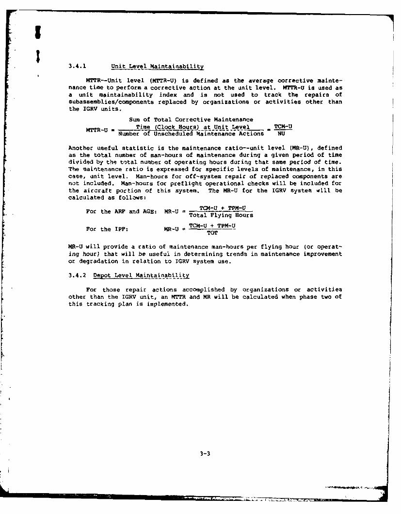
MTTR--Unit level (MTTR-U) is defined as the average corrective mainte-nance time to perform a corrective action at the unit level. MTTR-U is used asa unit maintainability index and is not used to track the repairs ofsubassemblies/components replaced by organizations or activities other thanthe IGRV units.
Sum of Total Corrective Maintenance
MTTR-U = Time (Clock Hours) at Unit Level TCM4-UNumber of Unscheduled Maintenance Actions NU
Another useful statistic is the maintenance ratio--unit level (MR-U), defined
as the total number of man-hours of maintenance during a given period of timedivided by the total number of operating hours during that same period of time.The maintenance ratio is expressed for specific levels of maintenance, in thiscase, unit level. Man-hours for off-system repair of replaced components arenot included. Man-hours for preflight operational checks will be included forthe aircraft portion of this system. The MR-U for the IGRV system will becalculated as follows:
For the ARF and AGE: MR-U = TC-U + TP-UTotal Flying Hours
For the IPF: MR-U -TCU+TPMUTOT
MR-U will provide a ratio of maintenance man-hours per flying hour (or operat-ing hour) that will be useful in determining trends in maintenance improvementor degradation in relation to IGRV system use.
3.4.2 Depot Level Maintainability
For those repair actions accomplished by organizations or activitiesother than the IGRV unit, an MTTR and MR will be calculated when phase two ofthis tracking plan is implemented.
[-
3-3

CHAPTER FOUR
RAM DATA COLLECTION PROCESS
4.1 OVERVIEW
The goal of the RAM data collection process is to generate a complete,accurate, and timely data base within the organizational and budgetary limita-tions of the PM SEMA. Most of the specific data elements identified in ChapterThree of this plan can be obtained from standard DA Forms 1352, 2406, and 2407,when they are properly completed. Recording, collecting, verifying, andaccumulating the requisite data elements are the subjects of this chapter.
4.2 DATA SOURCES
The data elements identified in Chapter Three are generally availablefrom DA Forms 1352, 2406, and 2407. (The notable exceptions are total oper-
ating time and total corrective maintenance clock time. Those data are dis-cussed further below.) These are standard U.S. Army forms; descriptions of theforms are given in Annex E. Specific sources of the data elements are asfollows:
- Total corrective maintenance time - system/subsystem downtime, TCM:DA Form 1352, Blocks 10i and 10j (NMCM for AVIM and AVUM) for theRC-12D and DA Form 2406, column M of Blocks 9i and 9j (non-availabledays) for the ARF, IPF, and AGE Van.
- Total preventive maintenance time - system/subsystem downtime, TPM:Not separately recorded. It is assumed that TPM is included in DA Form1352, Block 10j, for the RC-12D. TPM for the ARF, rPF, and AGE Van areassumed to be insignificant since the preventive maintenance checks
- I and services (PMCS) for the equipments in those subsystems generallycan be accomplished while the equipment is operating and result in nodowntime.
- Total administrative logistics delay time - system/subsystem delaytime, TALDT: DA Form 1352, Block lOg (non-mission capable supply) forthe RC-12D and DA Form 2406, Column S of Blocks 9i and 9j (non-available days) for the ARF, IPF, and AGE Van.
- Total corrective maintenance time - All unscheduled maintenance ac-tions, TCM: DA Form 2407, Block 20g (man-hours). The parameter of
4-1 -j
interest here is elapsed maintenance clock time. For purposes of thisplan, the data entered in block 20g are assumed to be the singlerepairman clock time for the maintenance actions recorded.
- Total administrative and logistics delay time - All unscheduled main-tenance actions, TALDT: DA Form 2407, Blocks 23, 27 (Julian dates),and 20g (elapsed time, see TCM above).I
TALDT = ((Block 27 - Block 23) x 24) - Block 20g
Since Blocks 23 and 27 record Julian dates, the result of the subtrac-tion of Block 23 from Block 27 must be multiplied by 24 to convert thenumber of days to hours.
- Maintenance man-hours: DA Form 2407, summation of entries in Block 20g
- Total flying hours: DA Form 1352, Block 10k
- Total calendar time: Total number of hours in the reporting period.
- Total operating time, TOT: Since there are no time meters on IGRVhardware, TOT must be estimated on the basis of a known parameter--flying hours. The following ratios are recommended for conversionfrom flying hours to operating hours:
-- Airborne equipment: Assume 1 hour ground operating time for pre-flight and post-flight checks. Assume 5 flight hours per aircraftper mission. The ratio of operating hours to flying hours is6:5 = 1.2
-- AGE Van: Assume the van is used for 2.5 hours to check out 2mission aircraft, or about 1.25 hours for each aircraft. Assume a5 hour flying mission. The ratio of operating hours to flyinghours is 1.25:5 = 0.25
-- IPF: Assume the IPF operates approximately 7.5 hours for every 5hour mission. Assume all missions use 2 aircraft or 10 flyinghours. The ratio of operating hours to flying hours is7.5:10 = 0.75
- Number of unscheduled maintenance actions, NU: The number of actionsreported equals the number of DA Form 2407s.
- Number of operational mission failures, NO: For the RC-12D, thisfigure can be determined from submissions of DA Form 1352. For theother subsystems, submissions of DA Form 2407 must be screened todetermine which maintenance actions result in an operational missionfailure. In Annex A, the column labeled "Miss ion-Essent ial" showswhether a particular LRU must be operational to make the subsystemsmission-capable. (Where there is LRU redundancy, the column indicatesthe minimum quantity required for mission capability.)
4.3 DATA COLLECTION
Two methods of data collection are available to PM SEMA for the purpose ofRAM tracking. They are commonly referred to as free-flow and semicontrolleddata collection.
4-2
II4.3.1 Free-Flow Data Collection
In the free-flow data collection process, PM SEMA currently has access toDA Form 1352 data. To enhance the RAM data base, operational IGRV units must
ensure that data files are maintained in accordance with The Army MaintenanceManagement System (TAMMS - TM 38-750) and the provisions of this tracking plan.Additionally, the IGRV units must he directed to forward copy 4 of all DA Form2407s to PM SEMA at the end of thu 90-day retention period required by TM 38-750. It is anticipated that following the initial 90-day period, IGRV unitswill submit data records monthly, as consecutive 90-day periods expire.
In addition, PM SEMA will initiate steps to have IGRV subsystems (ARF,IPF, and AGE Van) included in TAMMS, TM 38-750, paragraph 4-6, List of Itemsfor Material Condition Statis Report (DA Form 2406). DA Form 2406 then willprovide availability information at the subsystem level. Specifically, itwill quantify administrat:ve and logistics delay time as -ell as maintenancedowntime for reportabl- eAjipment. The parameters of interest from DA Form2406 are not miss on c: pa-e maintenance (NMCM) and not mission capable supply(NMCS). While NMCM and NMCS iata are available on DA Form 1352 for theaircraft, they are not . -fted at the present time for the AGE Van, IPF, orARF.
4.3.1.1 Detailed Data Flow
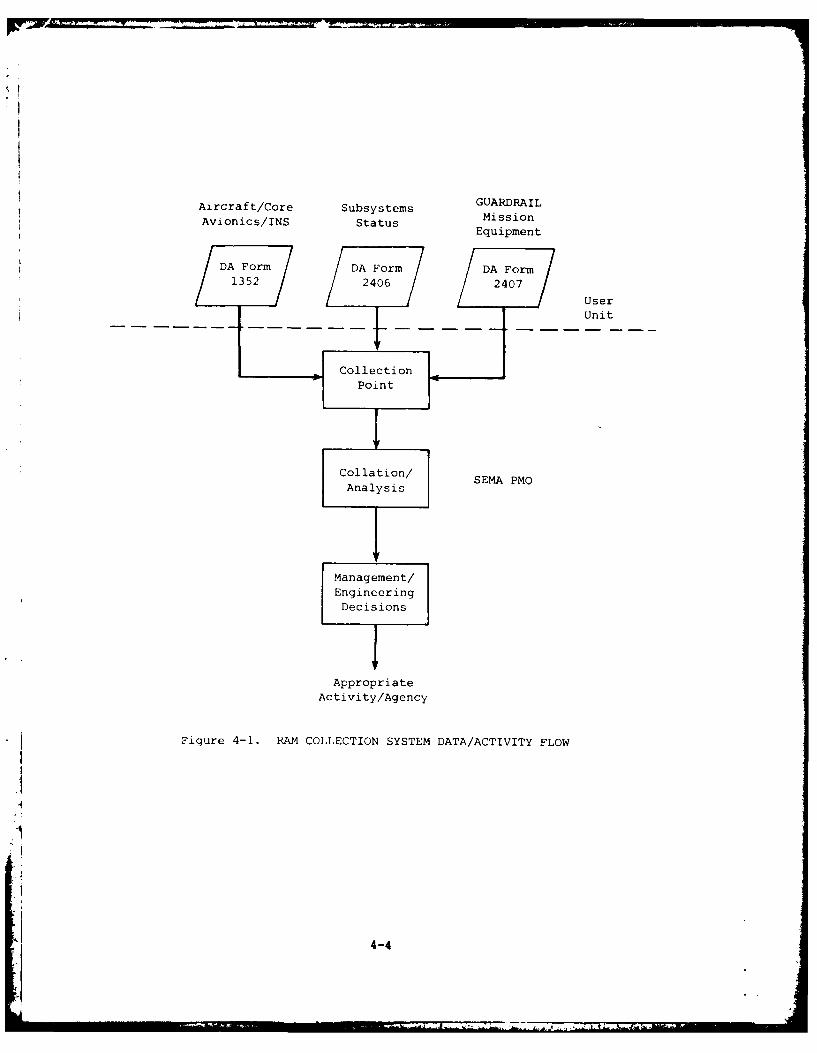
Under this free flow data collection process, PM SEMA must provide for thecollection and processinq of RAM data within TSARCOM. DA Forms 1352, 2406, and2407 completed by IGRV units will be forwarded to a central collection pointlocated within the SEMA Program Management Office (PMO) . This collection pointwill be the central repository for all data inputs from the field sites.Figure 4-1 anO the following paragraphs describe the process:
- DA Form 1352 is generated at the user unit and forwarded to the PM SEMAcollection point by mail. This form will track aircraft flying hours,plus full mission capable (FMC) , partial mission capable (PMC), andnot mission capable (NMC) hours for the RC-12D.
- DA Form 2406 also is generated at the use: unit level and forwarded.It will track NMCS and NMCM data elements for the ARF, IPF, and AGEVans.
- DA Form 2407 will be completed at the IGRV unit and forwarded by mailto the collection point. It will track LRU description, serial number,failure description, maintenance man-hours expended, and totalLRU/system downtime.
- From the collection point, the data will enter the collation/analysisprocess. The process can be accomplished either manually or by usingautomatic data processing (ADP). Given the volume of data expected,ADP appears to be the logical approach.
- The RAM reports generated as a result of the analysis process will beused for system management and engineering decisions by PM SEMA.Appropriate decisions and recommendations will then be forwarded tothe appropriate activity/agency.
4-3
Aircraft/Core Subsystems GUARDRAILAvionics/INS Status MissionEquipment
Form DA Form DA Form1352 2406 2 User
Unit
CollectionPoint
Collation/ SEMA PMO
Analysis
1Management/EngineeringDecisions
AppropriateActivity/Agency
Figure 4-1. RAM COLLECTION SYSTEM DATA/ACTIVITY FLOW
4-4
Specific implementation instructions for this in-house system will bedeveloped upon selection of the free-flow data collection process as the methodof data collection.
4.3.1.2 In-House System Advantages
This proposed data collection system offers a number of advantages for PMSEMA:
- All organizational structures are already in place and functioning in
the field.
- All necessary forms are in world-wide use as required by TM 38-750.
- No specialized training will be required for personnel at the IGRV unit
and support maintenance levels. Some training reinforcement might berequired to ensure accuracy and completeness in entering data in DAforms.
- No specialized data transmission facilities will be required.
- All data analysis could be performed within SEMA PMO, reducingsecurity-related problems.
- The data reduction and analysis can be performed on organic U.S. ArmyADP machines without additional capital investment for computer equip-ment. However, some software may have to be developed for formattingthe IGRV-peculiar reports.
4.3.2 Semicontrolled Data Collection
Reliance on free flow data collection places the entire burden of dataaccuracy and completeness on the on-site Army personnel. By means of semi-controlled data collection processes, various Army agencies (including theTSARCOM UH-lH Helicopter Program) have increased data collection accuracy andreduced administrative burdens. Under a semicontrolled data collectionprocess, PM SEMA would contract for on-site assistance in collecting and veri-fying maintenance data records (DA Forms 2406 and 2407). The most widely usedform of semicontrolled data collection is under the Sample Data Collection(SDC) Program in accordance with AR 750-37. There are several advantages tothe SDC Program:
- All necessary reliability and maintainability data are completely andaccurately collected at the designated site. This would include thespecial data provisions of this plan.
- No additional workload is imposed on on-site Army personnel.
- Sampling techniques conform to AR 750-37.
- A full range of machine-generated reports would fulfill PM SEMAreliability and maintainability data requirements. (Availability datawould be available in DA Forms 1352 and 2406 as previously stated.)
- Minimum data collection, accumulation, and processing would be re-
quired at SEMA PMO.
4-5
4.4 DATA STORAGE
Following the collection of requisite data at the central repository,SEMA PNO, or SOC contractor, all data will be logged, reviewed forcompleteness, and prepared for automatic data processing in accordance with TM38-750-1, TAIS Field Comand Picedures. Reducing and storing these datawithin TSARCOM facilities would require dedicated personnel and possibly thegeneration of a software program tailored to meet the IGRV data reportrequirements. A more practical and immediately available method would be touse the sample data collection and data storage techniques currently developedand provided to TSARCOM for the UH-lH Helicopter Program, augmented by an in-house process to track availability.
The data storage technique will maintain a file of all collected raw data.Additionally, the RAM parameters specified in Chapter Three will be availablethrough the exercise of the developed software program. As the data basegrows, the historical record of the calculated RAM parameters will provide theinput for the data analysis discussed in Chapter Five.
4-6
'.3
CHAPTER FIVE
RAM DATA ANALYSIS
5.1 OVERVIEW
The reduction and analysis of the collected RAM data is a critical step inmeeting the goals of this plan. It is at this point in the system that usabledata become available to the PM SEMA in the form of RAM data reports.
These data reports will provide the PM SEMA with information necessary forthe following purposes:
- Assessing the RAM performance of IGRV equipments
- Evaluating the effectiveness of maintenance operations
- Monitoring RAM growth progress
- Determining the readiness posture of the IGRV system
- Assessing system logistics supportability
- Identifying logistics problems requiring further analysis
Individual RAM parameters can provide useful information when compared to a
standard, if that standard is known. For instance, an instantaneous MTBF canbe compared to a contractually specified MTBF. However, the data analysisroutines of this chapter provide a more powerful tool by showing historicaltrends in the change of specific RAM parameters. In addition, observing thetrends over a period of time provides the analyst with greater insight intocurrent and potential problems.
5.2 TECHNICAL REPORT REQUIREMENTS
A series of technical reports will be generated and updated quarterly toprovide PM SEMA with concise information and a trend analysis. The reportswill be structured to provide analytical tables, as well as graphic presenta-tions of the data.
The reports described below constitute a minimum of data requirements toassess RAM performance. Since raw data are maintained, the breadth of param-
eters may be expanded to meet unusual information needs as they arise.
5-1
k1
5.2.1 Reliability Report
This report will track the mean time between operational mission failure(MTBOMF) for each IGRV system and for its major subsystems: RC-12D aircraft,ARF mission avionics, IPF, and AGE Van. Additionally, mean time betweenunscheduled maintenance actions (MTBUMA) will be tracked for individual LRUs.The ten LRUs that generate the greatest number of maintenance actions will behighlighted.
5.2.2 Availability Report
This report will track the operational availability (A ) for each IGRVsystem (site) and for its major subsystems: aircraft, AR#, IPF, and AGE.Additionally, this report will show average administrative logistic delay time(ALDT) for each site by system, subsystem, and LRU.
5.2.3 Maintainability Report
This report will track for each IGRV system the mean time to repair--unitlevel and the maintenance ratio--unit level (MTTR-U, MR-U). These statisticswill be provided for each major subsystem. The report will highlight the tenLRUs that required the greatest expenditure of maintenance man-hours perquarter.
5.3 TECHNICAL REPORT GENERATION
Automatic data processing routines are currently available within theSample Data Collection Program to generate the reliability and maintainabilityreports required by Section 5.2. Minor software development may be requiredfor formatting and labeling IGRV tables and graphs.
Availability reports can be generated within TSARCOM. If automated pro-cedures are desired for the availability report, some software developmentwill probably be required.
5.4 REPORT GRAPHICS
Graphic presentation of data is an excellent method for displaying sta-tistics so they can be easily read and understood. The following RAM data canbe effectively displayed with graphics.
- A versus total flight hours0
- A versus calendar time0
- System/subsystem reliability versus calendar time
- ALDT versus calendar time
- MR-U versus calendar time
- Number of unscheduled maintenance actions versus calendar time
- MTTR-U versus calendar time
5-2
I
5.5 REPORT USE
The various reports supplied by the program software will be used by SEMAP140 managers to monitor system RAM characteristics and evaluate the effec-tiveness of earlier management decisions. These reports will provide SEMA PMOwith a historical RAM data base displaying the IGRV RAM growth.
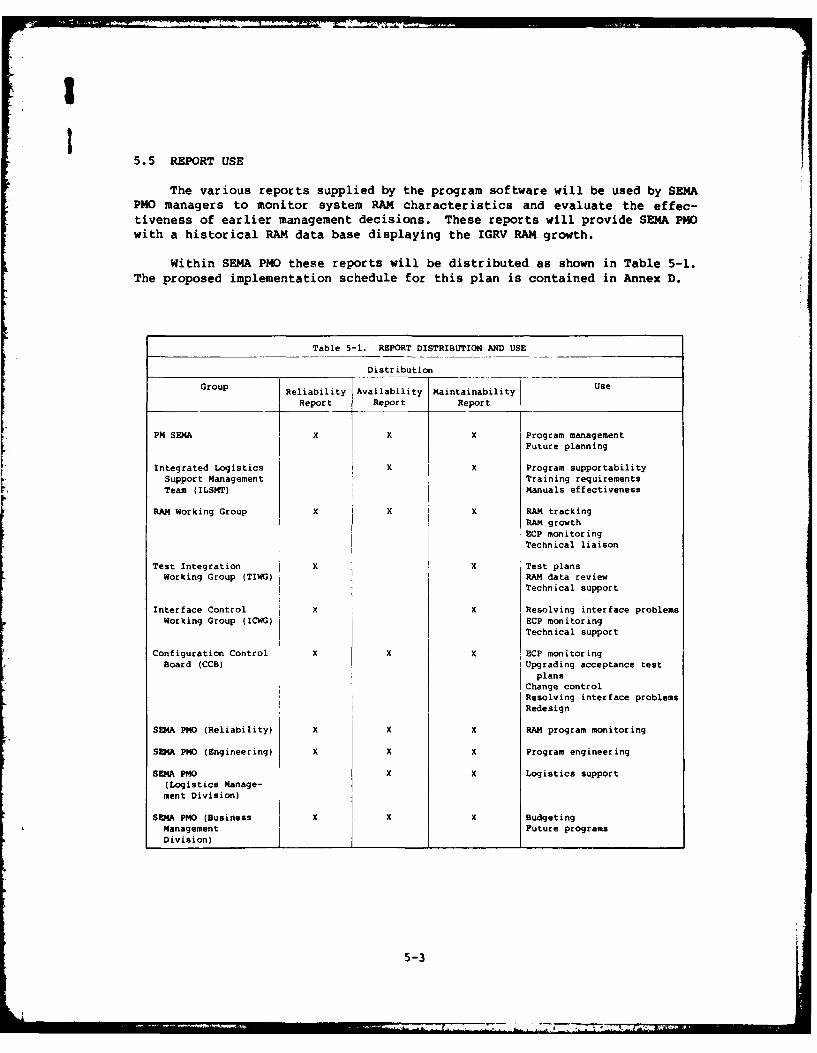
Within SEMA PMO these reports will be distributed as shown in Table 5-1.The proposed implementation schedule for this plan is contained in Annex D.
Table 5-1. REPORT DISTRIBUTION AND USE
Distribution
Group Reliability Availability Maintainability Use
Report Report Report
PM SEMA X X X Program managementFuture planning
Integrated Logistics x X Program supportabilitySupport Management Training requirementsTeam (ILSMT) Manuals effectiveness
RAM Working Group X X X RAM trackingRAM growthECP monitoringTechnical liaison
Test Integration X X Test plansWorking Group (TIWG) RAM data review
Technical support
Interface Control X X Resolving interface problemsWorking Group (ICWG) ECP monitoring
Technical support
Configuration Control X X X ECP monitoringBoard (CCB) Upgrading acceptance test
plans
Change controlResolving interface problemsRedesign
SEMA PMO (Reliability) X X X RAM program monitoring
SE4A PNO (Engineering) X X X Program engineering
SENA PMO X X Logistics support(Logistics Manage-ment Division)
SEMA PHO (Business X X X BudgetingManagement Future programsDivision)
5-3
I77
ANNEX A
LRIJ LISTS FOR M4AJOR SUBSYSTEMSOF IM4PROVED GUARDRAIL V
A-i
""x I
I
Sx x ......
x I I I I I I x x xI x x I x x . . . . . .
" zz 7 zzzz € zzzz z z z z z z z z
× × x × x xx
11
x 1. ,
A- 3
8! __C! 1
. . . . .
- - - - - - - - - 00 - - 0 - - -
C. ; 00 0 0 0 00 0 0 0 K K 0
1 1
.... .~~ ~ ~ t,. . . . . . . ..
8 8
A-4
-r
, -
3. , . -
j jt m
0
3' U)
-3 3 3 ×'× 3' 3 3 3
". 4, ; -, \
€ - - _ . . .. .. . . . . . . . . . .. . .
-I xC -
U U U U 0 U U
i C 0 C 0 0 0
-, ' C 'C C-' C C C '
O 0 0 0 0 00 000000 0 00 0 0 0 0 00 000000 00 0
0 0 DC 0 0 000 0. 00 0
-; --t_ _ - _
NO[ , N x, U
* I" NN C N
V, - -i : . .. .. Ni N; N N _
5 . f I N N O N N N N N N N N
N. ZN N. N U N. .N > Z> N N Z .N NO N
N N 000 NIO O1LIIIONIN O
o >I!g . . . . . . .
-- ------- _ .-
. . . s. . . . .... *t
S - S Sotot i
, O -
c
IV
- I - I ! t
C A-
A-9
-q 7 . . .. . . ._ _ _ _
:r
A-I
I
ANNEX B
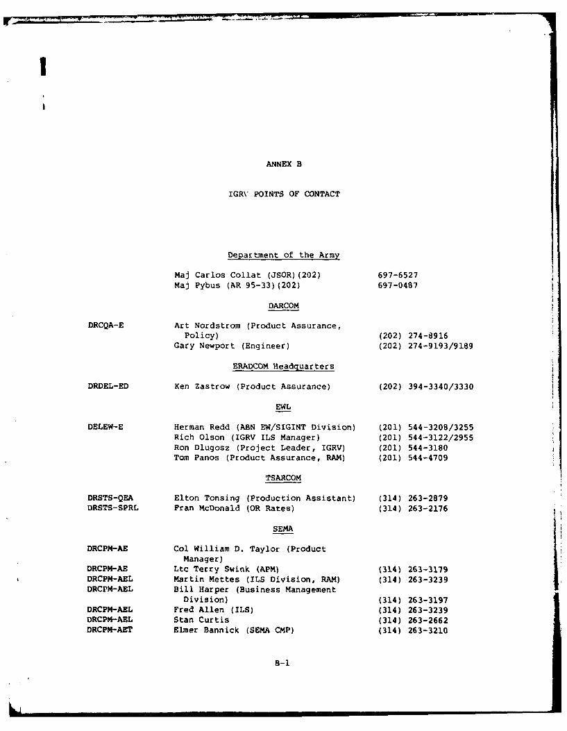
IGRV POINTS OF CONTACT
Department of the Army
Maj Carlos Collat (JSOR)(202) 697-6527Maj Pybus (AR 95-33)(202) 697-0487
DARCOM
DRCQA-E Art Nordstrom (Product Assurance,
Policy) (202) 274-8916Gary Newport (Engineer) (202) 274-9193/9189
ERADCOM Headquarters
DRDEL-ED Ken Zastrow (Product Assurance) (202) 394-3340/3330
EWL
DELEW-E Herman Redd (ABN EW/SIGINT Division) (201) 544-3208/3255Rich Olson (IGRV ILS Manager) (201) 544-3122/2955Ron Dlugosz (Project Leader, IGRV) (201) 544-3180Tom Panos (Product Assurance, RAM) (201) 544-4709
TSARCOM
DRSTS-QEA Elton Tonsing (Production Assistant) (314) 263-2879DRSTS-SPRL Fran McDonald (OR Rates) (314) 263-2176
SEMA
DRCPM-AE Col William D. Taylor (ProductManager)
DRCPM-AE Ltc Terry Swink (APM) (314) 263-3179DRCPM-AEL Martin Mettes (ILS Division, RAM) (314) 263-3239DRCPM-AEL Bill Harper (Business Management
Division) (314) 263-3197DRCPM-AEL Fred Allen (ILS) (314) 263-3239DRCPM-AEL Stan Curtis (314) 263-2662DRCPM-AET Elmer Bannick (SEMA CMP) (314) 263-3210
B-1
L ih I
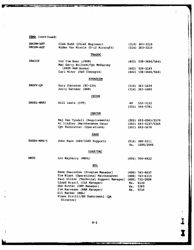
SEMA (continued)
DRCPM-AET Clem Mudd (Chief Engineer) (314) 263-3210
DRCPM-AET Alden Van Winkle (C-12 Aircraft) (314) 263-3210
TRADOC
USAICS Ltc Jim Baer (JSOR) (602) 538-3666/5641Maj Garry Bullock/Cpt McGarvey
(JSOR RAM Annex) (602) 538-2165Carl Minor (O&O Concepts) (602) 538-3666/5641
AVRADCOM
DRDPV-QR Gary Johnston (RC-12D) (314) 263-1639Jerry Dettmer (ASE) (314) 263-1480
CECOM
DRSEL-MMEI Bill Lewis (CTT) AV 532-3122(201) 544-5781
INSCOM
Maj Dan Tyndall (Requirements) (202) 692-2565/2579Al Lindley (Maintenance Data) (202) 692-5197/5345Cpt Hutstetter (Operations) (202) 692-5678
SAAD
SDSSA-MPE-5 John Haas (GRV/IGRV Support) (916) 388-2211Ex. 3288/2086
USAF/TAC
DRCG Ltc Mayberry (WBDL) (804) 764-4422
ESL
Dave Swainston (Program Manager) (408) 743-6037Tim Black (Operational Maintenance) (408) 743-6313Paul Dillon (Technical Support Manager) (408) 732-2888Lloyd Brazil (ILS Manager) Ex. 6120Don Rutter (CMP Manager) Ex. 5365Jim Narveson (RAM Manager) Ex. 5710Gil Barber (REL)Vince Sivilli/Ed Dumbrowski (QA
Director)
B-2
I
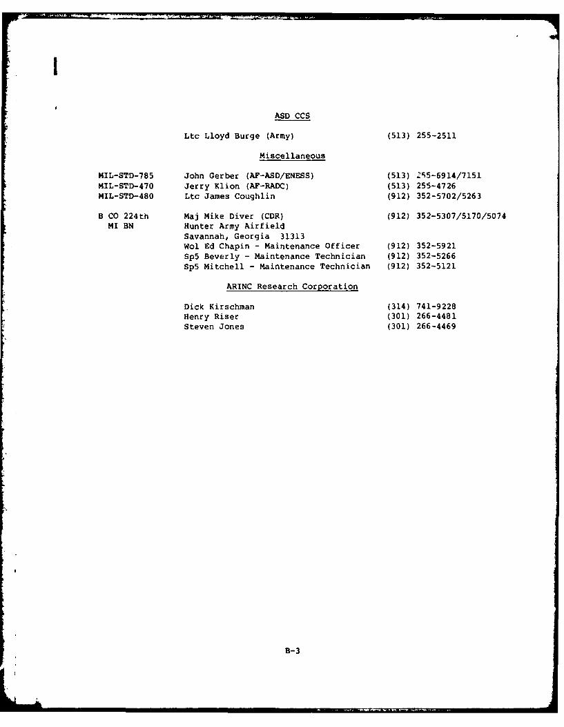
ASD CCS
Ltc Lloyd Burge (Army) (513) 255-2511
Miscellaneous
MIL-STD-785 John Gerber (AF-ASD/ENESS) (513) 215-6914/7151MIL-STD-470 Jerry Klion (AF-RADC) (513) 255-4726MIL-STD-480 Ltc James Coughlin (912) 352-5702/5263
B CO 224th Maj Mike Diver (CDR) (912) 352-5307/5170/5074MI BN Hunter Army Airfield
Savannah, Georgia 31313Wol Ed Chapin - Maintenance Officer (912) 352-5921Sp5 Beverly - Maintenance Technician (912) 352-5266Sp5 Mitchell - Maintenance Technician (912) 352-5121
ARINC Research Corporation
Dick Kirschman (314) 741-9228Henry Riser (301) 266-4481Steven Jones (301) 266-4469
B-3
I
I
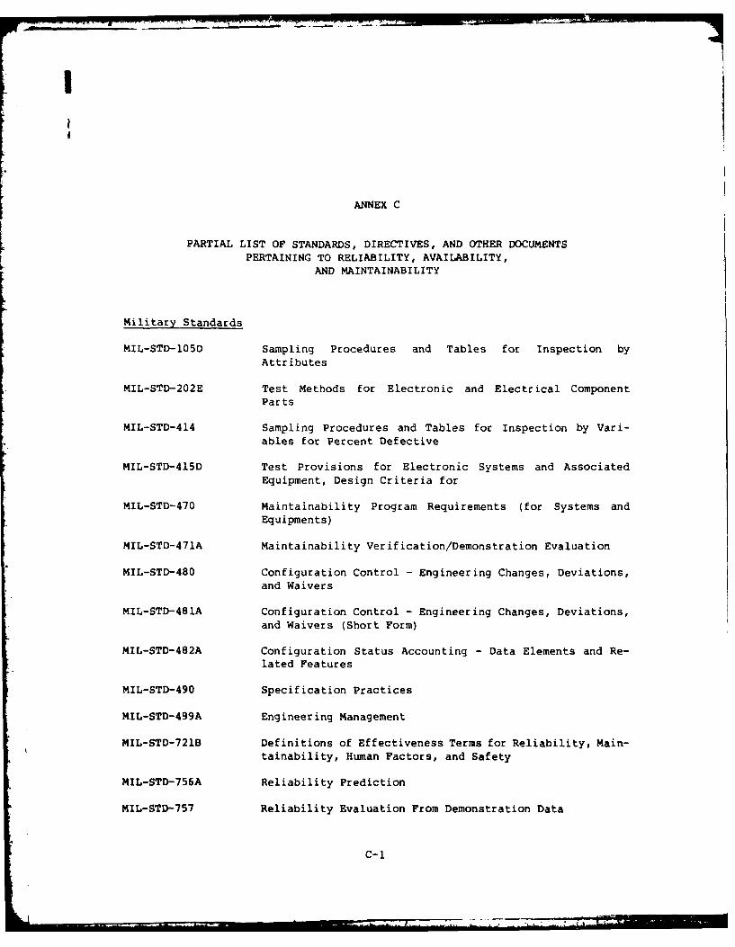
ANNEX C
PARTIAL LIST OF STANDARDS, DIRECTIVES, AND OTHER DOCUMENTSPERTAINING TO RELIABILITY, AVAILABILITY,
AND MAINTAINABILITY
Military Standards
MIL-STD-105D Sampling Procedures and Tables for Inspection byAttributes
MIL-STD-202E Test Methods for Electronic and Electrical ComponentParts
MIL-STD-414 Sampling Procedures and Tables for Inspection by Vari-ables for Percent Defective
MIL-STD-415D Test Provisions for Electronic Systems and AssociatedEquipment, Design Criteria for
MIL-STD-470 Maintainability Program Requirements (for Systems andEquipments)
MIL-STD-471A Maintainability Verification/Demonstration Evaluation
MIL-STD-480 Configuration Control - Engineering Changes, Deviations,and Waivers
MIL-STD-481A Configuration Control - Engineering Changes, Deviations,and Waivers (Short Form)
MIL-STD-482A Configuration Status Accounting - Data Elements and Re-lated Features
MIL-STD-490 Specification Practices
MIL-STD-499A Engineering Management
MIL-STD-721B Definitions of Effectiveness Terms for Reliability, Main-tainability, Human Factors, and Safety
MIL-STD-756A Reliability Prediction
MIL-STD-757 Reliability Evaluation From Demonstration Data
C-1

MIL-STD-780E(AS) Work Unit Codes for Aeronautical Equipment; Uniform Num-bering System
MIL-STD-781B Reliability Design Qualification and Production Accept-with Notice 1 ance Tests: Exponential Distribution
MIL-STD-781C Reliability Tests: Exponential Distribution
MIL-STD-785B Reliability Program for Systems and Equipment Development
and Production
MIL-STD-790C Reliability Assurance Program for Electronic Parts
Specifications
MIL-STD-881A Work Breakdown Structures for Defense Material Items
MIL-STD-882A System Safety Program Requirements
MIL-STD-965 Parts Control Program
MIL-STD-1304A Reliability Report
MIL-STD-1388-1 Logistics Support Analysis
MIL-STD-1472B Human Engineering Design Criteria for Military Systems,Equipment, and Facilities
MIL-STD-1521 Technical Reviews and Audits for Systems, Equipment, and
Computer Programs
MIL-STD-2068 (AS) Reliability Development Tests
MIL-STD-2070(AS) Procedures for Performing a Failure Modes, Effects, and
Criticality Analysis for Aeronautical Equipment
MIL-STD-2072(AS) Survivability, Aircraft; Establishment and Conduct ofPrograms
Military Specifications
MIL-H-46855B Human Engineering Requirements for Military Systems,Equipment, and Facilities
MIL-Q-9858A Quality Program Requirements
MIL-M-24365A Maintenance Engineering Analysis, Establishment of, andProcedures and Formats for Associated Documentation, Gen-eral Specification for
MIL-S-52779 Software Quality Assurance Program Requirements
C-2
77-7- Z=

I
MIL-T-21200 General Specification for Test Equipment for Use withElectronic and Electrical Equipment
Military Handbooks
MIL-HDBK-53 Guide for Sampling Inspection
MIL-HDBK-106 Multi-Level Sampling Procedures and Table for Inspectionby Attributes
MIL-HDBK-107 Inspection and Quality Control - Single Level ContinuousSampling Procedures and Tables fcr Inspection byAttributes
MIL-HDBK-108 Quality Control and Reliability - Sampling Procedures andTables for Life and Reliability Testing (Based on Expo-nential Distribution)
MIL-HDBK-109 Quality Control and Reliability - Statistical Proceduresfor Determining Validity of Supplier's Attributes,Inspection of
MIL-HDBK-175 Microelectronic Device Data Handbook
MIL-HDBK-i89 Reliability Growth Management
MIL-HDBK-217C Reliability Prediction of Electronic Equipment
MIL-HDBK-472 Maintainability Prediction
MIL-HDBK-251 Reliability/Design Thermal Applications
Army Documents
AMCP 11-3 Value Engineering Program Management Guidelines
DA PAM 11-25 Life Cycle System Management Model for Army Systems
Army Regulations
702-3 15 Nov 76 - Army Materiel Reliability, Availability, andMaintainability (RAM)
50-1 Army Materiel Maintenance Concepts and Policies
70-1 Army Research, Development and Acquisition - Change 1
70-10 Test and Evaluation During Development and Acquisition ofMateriel
C-3
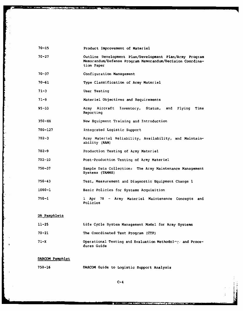
70-15 Product Improvement of Materiel
70-27 Outline Development Plan/Development Plan/Army ProgramMemorandum/Defense Program Memorandum/Decision Coordina-tion Paper
70-37 Configuration Management
70-61 Type Classification of Army Materiel
71-3 User Testing
71-9 Materiel Objectives and Requirements
95-33 Army Aircraft Inventory, Status, and Flying TimeReporting
350-XX New Equipment Training and Introduction
700-127 Integrated Logistic Support
702-3 Army Materiel Reliability, Availability, and Maintain-ability (RAM)
702-9 Production Testing of Army Materiel
702-10 Post-Production Testing of Army Materiel
750-37 Sample Data Collection: The Army Maintenance ManagementSystems (TAMMS)
750-43 Test, Measurement and Diagnostic Equipment Change 1
1000-1 Basic Policies for Systems Acquisition
750-1 1 Apr 78 - Army Materiel Maintenance Concepts andPolicies
DA Pamphlets
11-25 Life Cycle System Management Model for Army Systems
70-21 The Coordinated Test Program (CTP)
71-X Operational Testing and Evaluation Methodoe-j. and Proce-dures Guide
DARCOM Pamphlet
750-16 DARCOM Guide to Logistic Support Analysis
C-4
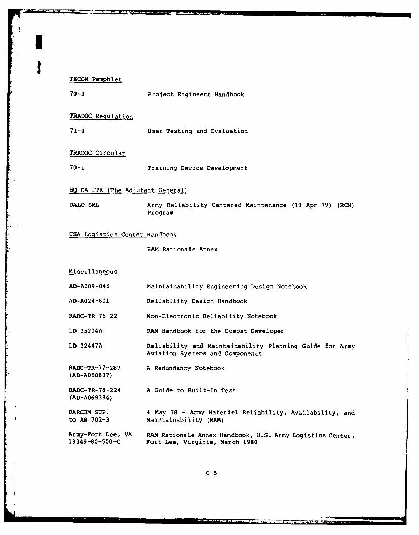
TECOM Pamphlet
70-3 Project Engineers Handbook
TRADOC Regulation
71-9 User Testing and Evaluation
TRADOC Circular
70-1 Training Device Development
HQ DA LTR (The Adjutant General)
DALO-SML Army Reliability Centered Maintenance (19 Apr 79) (RCM)Program
USA Logistics Center Handbook
RAM Rationale Annex
Miscellaneous
AD-A009-045 Maintainability Engineering Design Notebook
AD-A024-601 Reliability Design Handbook
RADC-TR-75-22 Non-Electronic Reliability Notebook
LD 35204A RAM Handbook for the Combat Developer
LD 32447A Reliability and Maintainability Planning Guide for ArmyAviation Systems and Components
RADC-TR-77-287 A Redundancy Notebook(AD-A050837)
RADC-TR-78-224 A Guide to Built-In Test(AD-A069384)
DARCOM SUP. 4 May 78 - Army Materiel Reliability, Availability, andto AR 702-3 Maintainability (RAM)
Army-Fort Lee, VA RAM Rationale Annex Handbook, U.S. Army Logistics Center,13349-80-500-C Fort Lee, Virginia, March 1980
C-5
Ar
ANNEX D
RAM TRACKING PLANIMPLEM4ENTAT ION SCHEDULE
D-1
I1
rTo 4
I04.44.4.
o >4
! 0)
4 I
I I4I--
II 1 Hii °' I
ANNEX E
DESCRIPTION OF DA FORMS
DA Form 2406, Material Condition Status Report (Figure E-1) provides:
- The DA Staff with a collection of information on those items of equip-ment which are considered essential and required a significant amountof maintenance to ensure operational reliability.
- Commanders at all levels with a means of forecasting equipment avail-ability based upon current and historical data. The forecasting
should be viewed as estimates since previous equipment downtime mayhave resulted from unusual or nonrecurring usage, climate conditions,or abuse.
- Unit commanders who are required to report unit status in accordancewith AR 220-1, with a worksheet for computing equipment status (ES) andequipment readiness (ER).
- Commanders of logistics supporting activities with the status ofequipment of the supported units.
This form allows the user to track equipment by quantity, availability,and supply and maintenance downtime. DA Form 2406 is completed monthly by allArmy units for equipment listed in paragraph 4.6 of TM 38-750.
DA Form 2407, Maintenance Request (Figure E-2) is used to:
- Request maintenance from direct support or a higher level maintenanceshop
- Request/report the accomplishment of modification work orders (MWO) onall Army aircraft and components
- Submit warranty claim actions
- Serve as a source document for the Sample Data Collection (SDC) Program
- Track work completed by maintenance man-hours
This form allows the user to track equipment repairs by LRU and serialnumber, parts replaced, and repair man-hours.
E-1

.DA Form 1352, Army Aircraft Inventory, Status, and Flying Time Reporting(Figure E-3) is used to:
- Account for aircraft flying hours by task number
- Provide tracking f or aircraft mechanical problems affecting safety offlight
- Provide data on aircraft not mission capable maintenance (N41.E) andnot mission capable supply (NMC) characteristics
This form will allow the user to track flying hours for each aircraftassigned to a GUARDRAIL unit. This form will provide the main data input fordetermining total operating time (TOT) of the system.
E-2