S TRUCTURAL V IOLENCE Tuream West Globalization and Human Rights.
D-SEAMS: DEFERRED STRUCTURAL ELUCIDATION ANALYSISFOR MOLECULAR SIMULATIONS
A PREPRINT
Rohit Goswami∗Department of Chemical EngineeringIndian Institute of Technology Kanpur
Amrita Goswami†Department of Chemical EngineeringIndian Institute of Technology Kanpur
Jayant K. Singh‡Department of Chemical EngineeringIndian Institute of Technology Kanpur
August 12, 2020
ABSTRACT
Structural analyses are an integral part of computational research on nucleation and supercooledwater, whose accuracy and efficiency can impact the validity and feasibility of such studies. Theunderlying molecular mechanisms of these often elusive and computationally expensive processes canbe inferred from the evolution of ice-like structures, determined using appropriate structural analysistechniques. We present d-SEAMS, a free and open-source post-processing engine for the analysisof molecular dynamics trajectories, which is specifically able to qualitatively classify ice structures,in both strong confinement and bulk systems. For the first time, recent algorithms for confined icestructure determination have been implemented, along with topological network criteria for bulk icestructure determination. Recognizing the need for customization in structural analysis, d-SEAMS hasa unique code architecture, built with nix, employing a YAML-Lua scripting pipeline. The softwarehas been designed to be user-friendly and easy to extend. The engine outputs are compatible withpopular graphics software suites, allowing for immediate visual insights into the systems studied. Wedemonstrate the features of d-SEAMS by using it to analyze nucleation in the bulk regime and forquasi-one and quasi-two-dimensional systems. Structural time evolution and quantitative metricsare determined for heterogenous ice nucleation on a silver-exposed β-AgI surface, homogenous icenucleation, flat monolayer square ice formation and freezing of an ice nanotube.
Keywords structure-determination, analysis-engine, computational-chemistry, nix, lua, cpp
1 Introduction
The increase in power and efficiency of high-performance computing resources have enabled researchers to directlyobserve nucleation events in molecular-dynamics simulations. Concomitantly, the determination of ice-like structuresfrom simulations is essential for the interpretation of nucleation events, since trajectories provide positional data ofparticles, and do not explicitly track crystal structures and defects [1]. Nucleation of soft-matter is further complicatedby the emergence of competing ice polymorphs [2, 3] with small free energy differences [4]. The ice-like structuresformed are also continually distorted by thermal fluctuations, which locally disrupt long-range order. These issues can
∗Currently at the Department of Chemistry, IIT Kanpur, equal contribution†equal contribution‡Corresponding Author
arX
iv:1
909.
0983
0v3
[ph
ysic
s.co
mp-
ph]
13
Jan
2020
D-SEAMS PREPRINT - AUGUST 12, 2020
make automated and accurate structural determination intractable, especially for weakly crystalline regions [5]. Surfaceinteractions and confinement can strongly influence nucleation behaviour [6–8], which add to the complexity of thestructure determination problem.
Water is a deceptively simple molecule, exhibiting rich and complex phase behaviour in bulk and confinement [9–19].At least 17 bulk ice polymorphs have been observed experimentally [20, 21]. Water confined within nanometer lengthscales exhibits even more diversity, forming ordered hydrogen-bond networks of ice nanotubes, monolayers, bilayersand trilayers [17, 22–28]. The structural determination of the several possible polymorphs of water, in bulk and inconfinement, is of crucial importance in the qualitative and quantitative analysis of simulation data. The analysis ofthe evolution of ordered structures during a nucleation event is desirable, since it can reveal details of the underlyingmolecular mechanism and provide important physical insights into the system.
In this work, we present d-SEAMS, a cohesive post-processing structural analysis engine, which is capable of coherentlyclassifying water structures under strong confinement and in bulk systems, from quasi-one and two-dimensionalconfinement to bulk ice polymorphs. Confined ice polymorphs are often identified “by eye” wherein the hydrogen-bondnetwork (HBN) is manually inspected [17, 19, 26]. In particular, d-SEAMS automates the process of structural analysisand qualitative metric calculation, eliminating the need for visual inspection.
Conflicting package clashes due to transitive or indirect dependencies is a recurring problem in software developmentand use [29]. Resolving such issues can often be non-trivial, relying on removal of unnecessary dependencies, systemupdates (for most Linux clusters) and other manual strategies that may be ineffective for a complex dependency tree.These manual strategies are increasingly difficult to carry out on restricted access machines with high up-times, whichare common to the HPC (High Performance Computing) clusters, used for such computationally demanding simulations.
d-SEAMS circumvents the problem of ‘dependency hell’ by using nix [30] for generating reproducible dependencybuild-graphs [31]. Users can run d-SEAMS using the exact build-environment of the developers and vice-versa,bypassing installation and use issues on various systems and HPC clusters, ensuring reproducible results.
The parameters of structural analysis techniques are often tweaked to suit the specific requirements of the desiredstudy [32, 33]. d-SEAMS has been designed to permit easy extensions to the code and the implementation of customwork-flows. The engine simultaneously incorporates user-friendly interface functions without compromising onfunctionality. Key features implemented include a primitive ring analysis algorithm [34], topological network criteriafor bulk [35] and confined systems [36] and new qualitative order parameters. Popular analysis techniques, includingbond-orientational parameters [32, 37] and related criteria [38, 39], have also been implemented. Outputs are producedin formats compatible with popular visualization softwares, including OVITO [40] and VMD [41]. We describe howd-SEAMS has been used to analyze and characterize ice nucleation on an ice-promoting AgI surface, homogenous bulknucleation, the formation of monolayer ice and the freezing of a quasi-one-dimensional ice nanotube (INT).
2 Code Architecture
2.1 Nix Expressions for Reproducible Builds
Computational software implemented in declarative package management systems suffer from design concerns forthe end-users and the developers. The developers have the onus to package their software as per the many imperativesystems (Ubuntu and apt, RedHat and yum, ArchLinux and pacman). Additionally, the users must ensure that theinterrelated dependencies match perfectly. In essence, the issue is that the packages and versions at the time of build arenot guaranteed automatically at the user’s end, even if the software is packaged appropriately for the operating system.This issue stems from the fact that the configuration after installation is the result of a series of stateful transformationswhich cannot be reproduced [42]. We have opted to package our software as a nix-derivation [30], which also providesa functionally reproducible environment for reproducible bug-tests. Since the build system is essentially a static graphof build actions, the environment produced is a boon for reproducibility, avoiding circular build-time dependencies andincomplete dependency specifications [43]. More details on the design rationale are in the Electronic SupplementaryInformation.
2.2 Pipeline of Work-flows
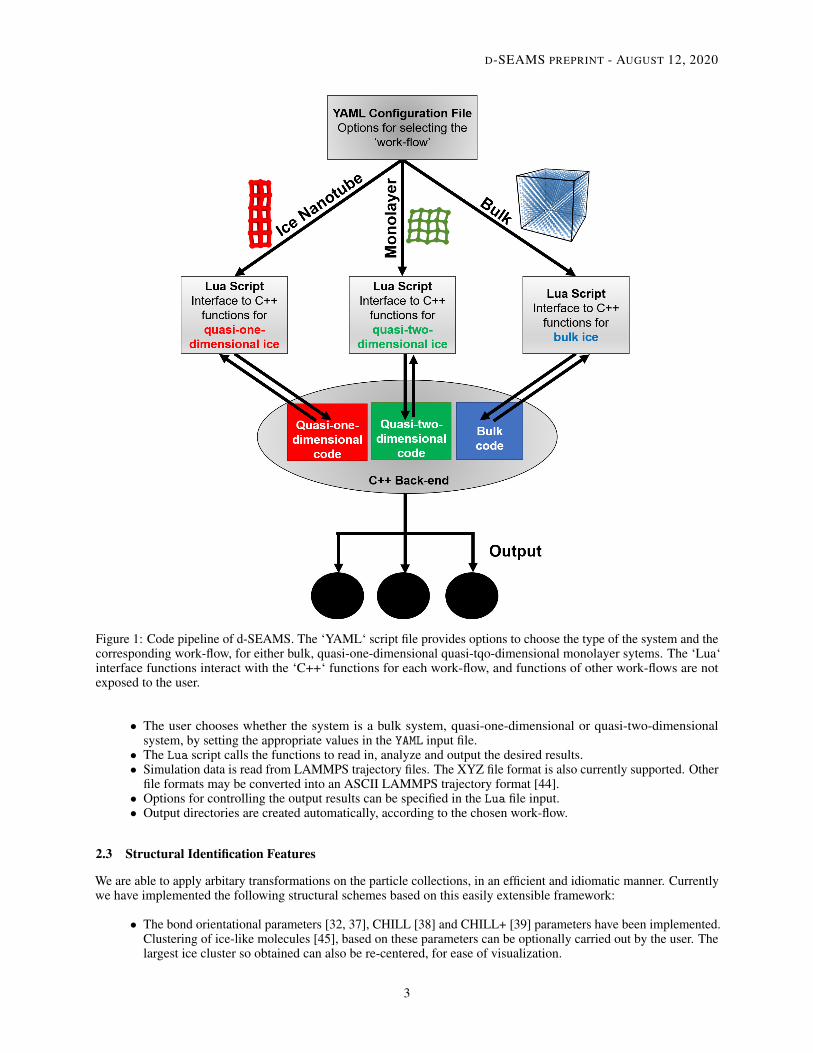
Figure 1 visually depicts the logical pipeline of typical work-flows in d-SEAMS. An input system can either be a bulksystem, a quasi-one-dimensional system or a quasi-two-dimensional system. The criteria and analysis algorithms tend todiffer across scales as well. Thus, we have separated the mutually exclusive work-flows for bulk, quasi-one-dimensionaland quasi-two-dimensional systems, with separate modular code blocks for each type of system. The general softwarepipeline is organized as follows:
2
D-SEAMS PREPRINT - AUGUST 12, 2020
Figure 1: Code pipeline of d-SEAMS. The ‘YAML‘ script file provides options to choose the type of the system and thecorresponding work-flow, for either bulk, quasi-one-dimensional quasi-tqo-dimensional monolayer sytems. The ‘Lua‘interface functions interact with the ‘C++‘ functions for each work-flow, and functions of other work-flows are notexposed to the user.
• The user chooses whether the system is a bulk system, quasi-one-dimensional or quasi-two-dimensionalsystem, by setting the appropriate values in the YAML input file.
• The Lua script calls the functions to read in, analyze and output the desired results.• Simulation data is read from LAMMPS trajectory files. The XYZ file format is also currently supported. Other
file formats may be converted into an ASCII LAMMPS trajectory format [44].• Options for controlling the output results can be specified in the Lua file input.• Output directories are created automatically, according to the chosen work-flow.
2.3 Structural Identification Features
We are able to apply arbitary transformations on the particle collections, in an efficient and idiomatic manner. Currentlywe have implemented the following structural schemes based on this easily extensible framework:
• The bond orientational parameters [32, 37], CHILL [38] and CHILL+ [39] parameters have been implemented.Clustering of ice-like molecules [45], based on these parameters can be optionally carried out by the user. Thelargest ice cluster so obtained can also be re-centered, for ease of visualization.
3
D-SEAMS PREPRINT - AUGUST 12, 2020
• Topological network criteria for bulk ice determination [35] have been implemented. d-SEAMS is able toidentify and write out detailed information about Double-diamond cages (DDCs), hexagonal cages (HCs), andmixed rings for every frame. Additionally, the number of basal and prismatic rings are also computed.
• Primitive rings are identified. First, all possible rings are found using an exhaustive backtracking algorithm,following which non-shortest path rings are removed [34]. Ring networks with only hydrogen-bondedconnections can be optionally determined.
• Confined quasi-two-dimensional ice classification by topological and graph theoretic approaches to thehydrogen-bonded ice-like particles.
• Quasi-one dimensional ice nano-tube (INT) and quasi-two-dimensional monolayer ice classification viatopological network criteria [36]. The building blocks of n-gonal prismatic ice are explicitly and unequivocallyidentified.
• d-SEAMS is capable of calculating geometric order parameters for describing the phase transitions in confinedice.
3 Applications
Using d-SEAMS, structural and qualitative information as a time series can be easily obtained. This makes it possibleto study a variety of diverse nucleating systems. Even the mechanism of nucleation growth can be inferred from anensemble of trajectories, by analyzing the qualitative metrics supported by d-SEAMS.
3.1 Bulk Systems
3.1.1 Heterogenous Nucleation on an Ice-Promoting Surface
Silver iodide is an effective ice nucleating agent, whose lattice closely resembles that of bulk ice [46]. The smoothAg-exposed β-AgI surface has been known to promote layer-by-layer growth of hexagonal ice (Ih) and cubic ice (Ic) insimulations [47]. Using d-SEAMS, we probe the underlying mechanism of the ice nucleation growth and behaviour.Ten independent simulations of 5120 TIP4P/Ice [48] molecules on a free-standing AgI surface were run upto ≈ 200 nsat 240K. The simulation setup is similar to that of previous work in the literature [49].
Here we employ a topological network criterion [35] for identifying the building blocks of Ih and Ic, called hexagonalcages (HCs) and double-diamond cages (DDCs), respectively. Rings which belong to both HCs and DDCs are classifiedas mixed rings.
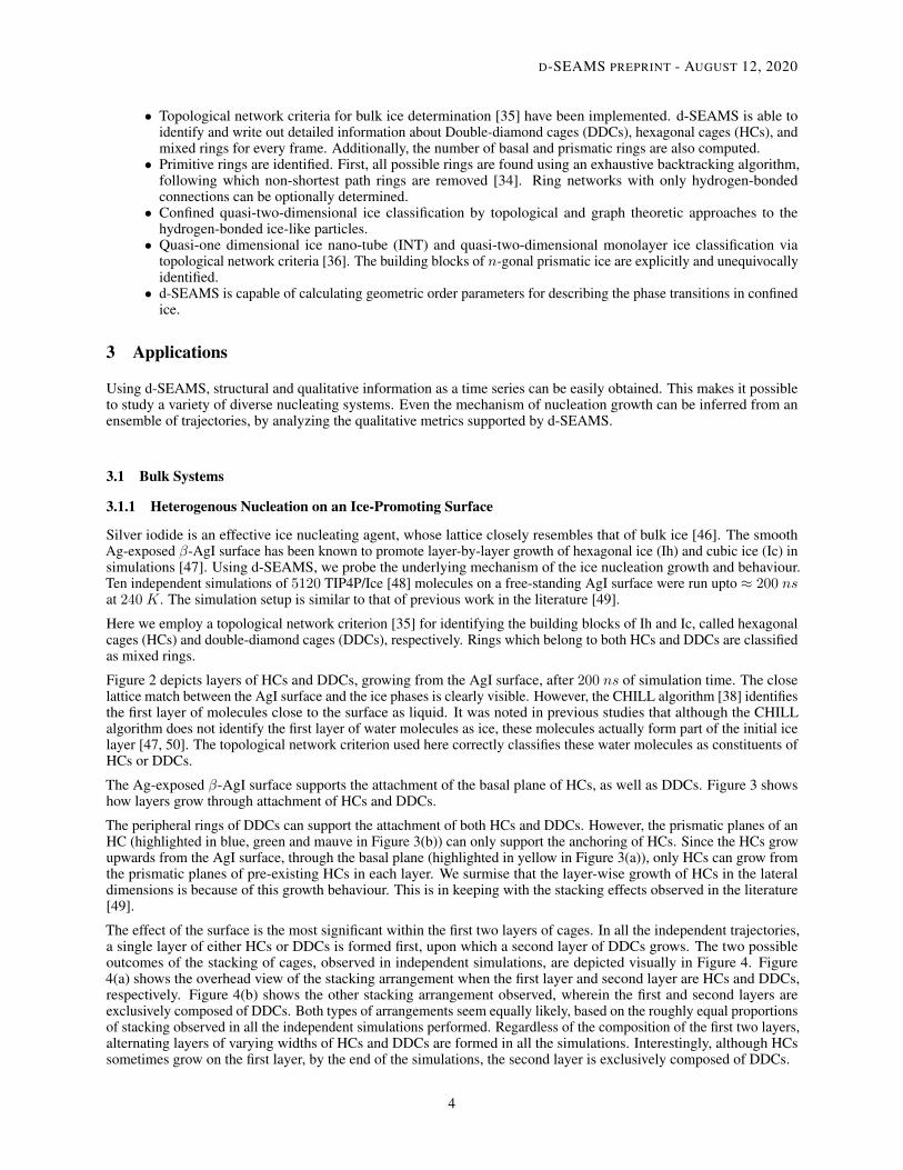
Figure 2 depicts layers of HCs and DDCs, growing from the AgI surface, after 200 ns of simulation time. The closelattice match between the AgI surface and the ice phases is clearly visible. However, the CHILL algorithm [38] identifiesthe first layer of molecules close to the surface as liquid. It was noted in previous studies that although the CHILLalgorithm does not identify the first layer of water molecules as ice, these molecules actually form part of the initial icelayer [47, 50]. The topological network criterion used here correctly classifies these water molecules as constituents ofHCs or DDCs.
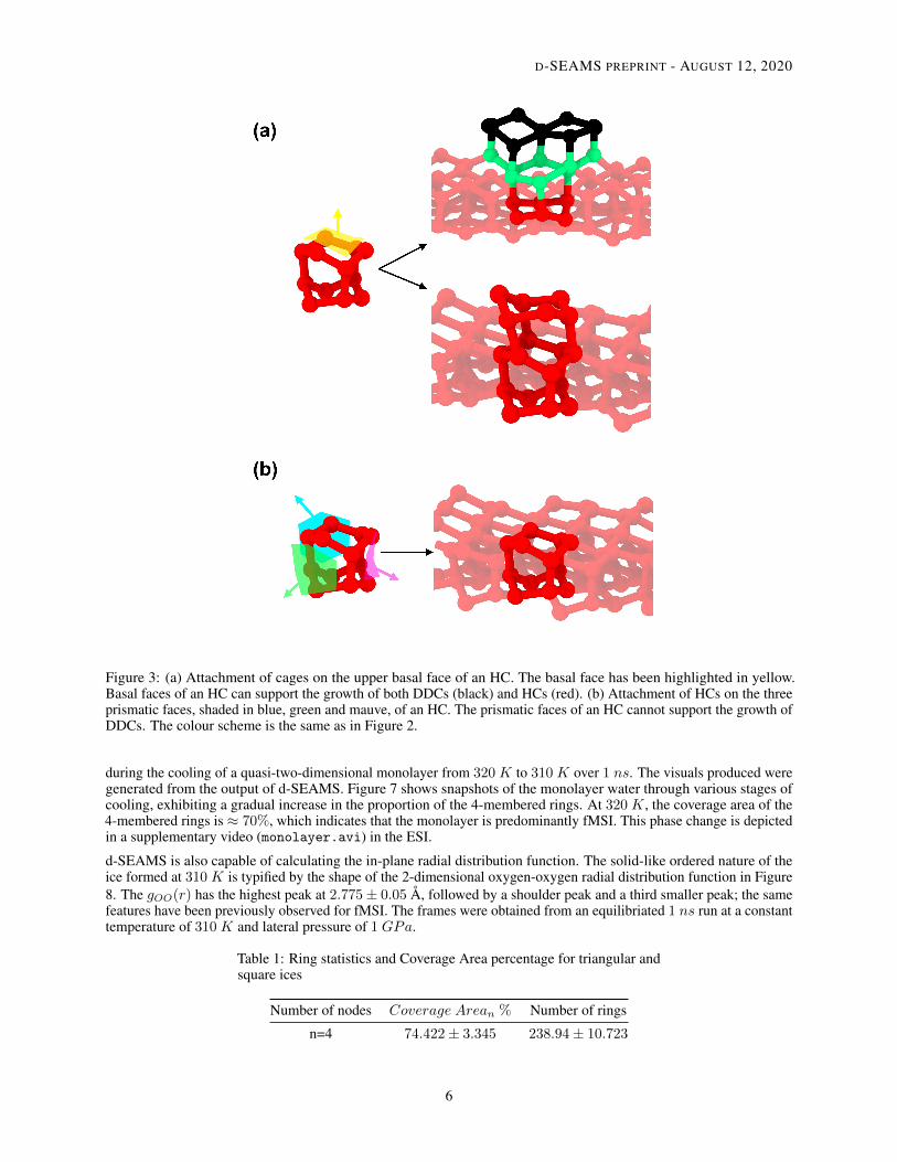
The Ag-exposed β-AgI surface supports the attachment of the basal plane of HCs, as well as DDCs. Figure 3 showshow layers grow through attachment of HCs and DDCs.
The peripheral rings of DDCs can support the attachment of both HCs and DDCs. However, the prismatic planes of anHC (highlighted in blue, green and mauve in Figure 3(b)) can only support the anchoring of HCs. Since the HCs growupwards from the AgI surface, through the basal plane (highlighted in yellow in Figure 3(a)), only HCs can grow fromthe prismatic planes of pre-existing HCs in each layer. We surmise that the layer-wise growth of HCs in the lateraldimensions is because of this growth behaviour. This is in keeping with the stacking effects observed in the literature[49].
The effect of the surface is the most significant within the first two layers of cages. In all the independent trajectories,a single layer of either HCs or DDCs is formed first, upon which a second layer of DDCs grows. The two possibleoutcomes of the stacking of cages, observed in independent simulations, are depicted visually in Figure 4. Figure4(a) shows the overhead view of the stacking arrangement when the first layer and second layer are HCs and DDCs,respectively. Figure 4(b) shows the other stacking arrangement observed, wherein the first and second layers areexclusively composed of DDCs. Both types of arrangements seem equally likely, based on the roughly equal proportionsof stacking observed in all the independent simulations performed. Regardless of the composition of the first two layers,alternating layers of varying widths of HCs and DDCs are formed in all the simulations. Interestingly, although HCssometimes grow on the first layer, by the end of the simulations, the second layer is exclusively composed of DDCs.
4
D-SEAMS PREPRINT - AUGUST 12, 2020
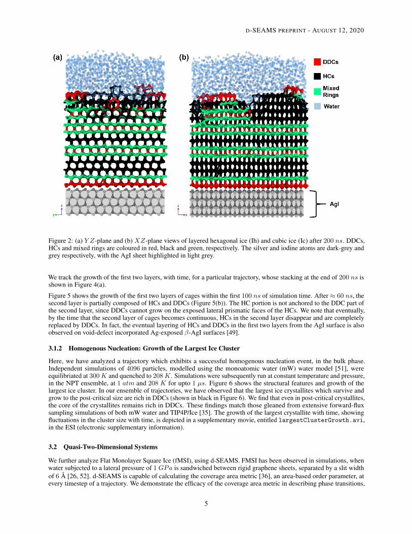
Figure 2: (a) Y Z-plane and (b) XZ-plane views of layered hexagonal ice (Ih) and cubic ice (Ic) after 200 ns. DDCs,HCs and mixed rings are coloured in red, black and green, respectively. The silver and iodine atoms are dark-grey andgrey respectively, with the AgI sheet highlighted in light grey.
We track the growth of the first two layers, with time, for a particular trajectory, whose stacking at the end of 200 ns isshown in Figure 4(a).
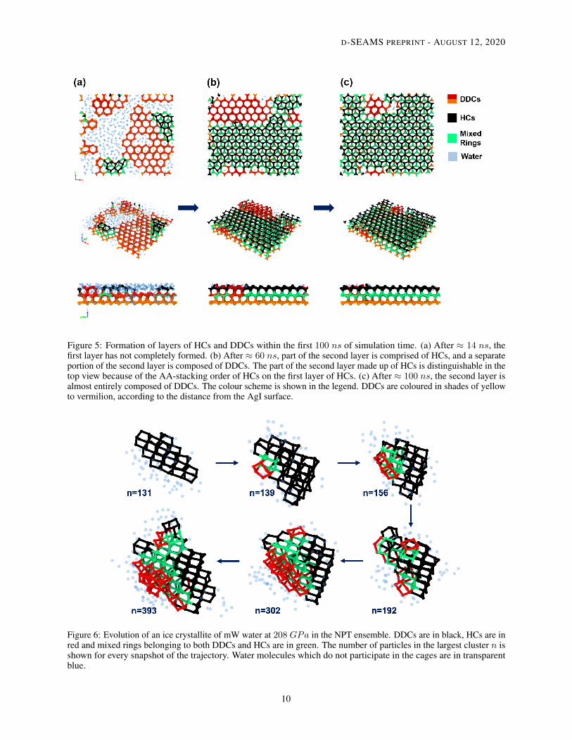
Figure 5 shows the growth of the first two layers of cages within the first 100 ns of simulation time. After ≈ 60 ns, thesecond layer is partially composed of HCs and DDCs (Figure 5(b)). The HC portion is not anchored to the DDC part ofthe second layer, since DDCs cannot grow on the exposed lateral prismatic faces of the HCs. We note that eventually,by the time that the second layer of cages becomes continuous, HCs in the second layer disappear and are completelyreplaced by DDCs. In fact, the eventual layering of HCs and DDCs in the first two layers from the AgI surface is alsoobserved on void-defect incorporated Ag-exposed β-AgI surfaces [49].
3.1.2 Homogenous Nucleation: Growth of the Largest Ice Cluster
Here, we have analyzed a trajectory which exhibits a successful homogenous nucleation event, in the bulk phase.Independent simulations of 4096 particles, modelled using the monoatomic water (mW) water model [51], wereequilibriated at 300K and quenched to 208K. Simulations were subsequently run at constant temperature and pressure,in the NPT ensemble, at 1 atm and 208 K for upto 1 µs. Figure 6 shows the structural features and growth of thelargest ice cluster. In our ensemble of trajectories, we have observed that the largest ice crystallites which survive andgrow to the post-critical size are rich in DDCs (shown in black in Figure 6). We find that even in post-critical crystallites,the core of the crystallites remains rich in DDCs. These findings match those gleaned from extensive forward-fluxsampling simulations of both mW water and TIP4P/Ice [35]. The growth of the largest crystallite with time, showingfluctuations in the cluster size with time, is depicted in a supplementary movie, entitled largestClusterGrowth.avi,in the ESI (electronic supplementary information).
3.2 Quasi-Two-Dimensional Systems
We further analyze Flat Monolayer Square Ice (fMSI), using d-SEAMS. FMSI has been observed in simulations, whenwater subjected to a lateral pressure of 1 GPa is sandwiched between rigid graphene sheets, separated by a slit widthof 6 Å [26, 52]. d-SEAMS is capable of calculating the coverage area metric [36], an area-based order parameter, atevery timestep of a trajectory. We demonstrate the efficacy of the coverage area metric in describing phase transitions,
5
D-SEAMS PREPRINT - AUGUST 12, 2020
Figure 3: (a) Attachment of cages on the upper basal face of an HC. The basal face has been highlighted in yellow.Basal faces of an HC can support the growth of both DDCs (black) and HCs (red). (b) Attachment of HCs on the threeprismatic faces, shaded in blue, green and mauve, of an HC. The prismatic faces of an HC cannot support the growth ofDDCs. The colour scheme is the same as in Figure 2.
during the cooling of a quasi-two-dimensional monolayer from 320K to 310K over 1 ns. The visuals produced weregenerated from the output of d-SEAMS. Figure 7 shows snapshots of the monolayer water through various stages ofcooling, exhibiting a gradual increase in the proportion of the 4-membered rings. At 320K, the coverage area of the4-membered rings is ≈ 70%, which indicates that the monolayer is predominantly fMSI. This phase change is depictedin a supplementary video (monolayer.avi) in the ESI.
d-SEAMS is also capable of calculating the in-plane radial distribution function. The solid-like ordered nature of theice formed at 310K is typified by the shape of the 2-dimensional oxygen-oxygen radial distribution function in Figure8. The gOO(r) has the highest peak at 2.775± 0.05 Å, followed by a shoulder peak and a third smaller peak; the samefeatures have been previously observed for fMSI. The frames were obtained from an equilibriated 1 ns run at a constanttemperature of 310K and lateral pressure of 1 GPa.
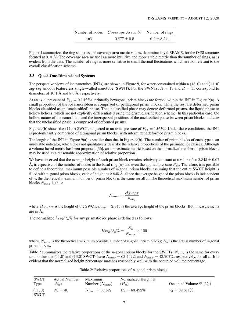
Table 1: Ring statistics and Coverage Area percentage for triangular andsquare ices
Number of nodes Coverage Arean % Number of rings
n=4 74.422± 3.345 238.94± 10.723
6
D-SEAMS PREPRINT - AUGUST 12, 2020
Number of nodes Coverage Arean % Number of rings
n=3 0.877± 0.5 6.2± 3.544
Figure 1 summarizes the ring statistics and coverage area metric values, determined by d-SEAMS, for the fMSI structureformed at 310K. The coverage area metric is a more intuitive and more stable metric than the number of rings, as isevident from the data. The number of rings is more sensitive to small thermal fluctuations which are not relevant to theoverall classification scheme.
3.3 Quasi-One-Dimensional Systems
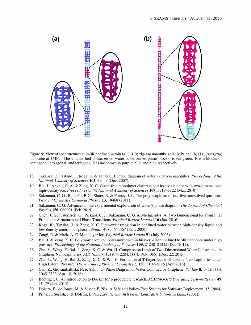
The perspective views of ice nanotubes (INTs) are shown in Figure 9, for water constrained within a (13, 0) and (11, 0)zig-zag smooth featureless single-walled nanotube (SWNT). For the SWNTs, R = 13 and R = 11 correspond todiameters of 10.1 Å and 8.6 Å, respectively.
At an axial pressure of Pzz = 0.1MPa, primarily hexagonal prism blocks are formed within the INT in Figure 9(a). Asmall proportion of the ice nanoribbon is comprised of pentagonal prism blocks, while the rest are deformed prismblocks classified as an ‘unclassified’ phase. The unclassified phase may denote deformed prisms, the liquid phase orhollow helices, which are not explicitly differentiated using the prism classification scheme. In this particular case, thehollow nature of the nanoribbon and the interspersed positions of the unclassified phase between prism blocks, indicatethat the unclassified phase is comprised of deformed prisms.
Figure 9(b) shows the (11, 0) SWCT, subjected to an axial pressure of Pzz = 1MPa. Under these conditions, the INTis predominantly comprised of tetragonal prism blocks, with intermittent deformed prism blocks.
The length of the INT in Figure 9(a) is smaller than that in Figure 9(b). The number of prism blocks of each type is anunreliable indicator, which does not qualitatively describe the relative proportions of the prismatic ice phases. Althougha volume-based metric has been proposed [36], an approximate metric based on the normalized number of prism blocksmay be used as a reasonable approximation of relative proportion.
We have observed that the average height of each prism block remains relatively constant at a value of ≈ 2.845± 0.07Å, irrespective of the number of nodes in the basal ring (n) and even the applied pressure Pzz . Therefore, it is possibleto define a theoretical maximum possible number of n-gonal prism blocks, assuming that the entire SWCT height isfilled with n-gonal prism blocks, each of height ≈ 2.845 Å. Since the average height of the prism blocks is independentof n, the theoretical maximum number of prism blocks is the same for all n. The theoretical maximum number of prismblocks Nmax is thus:
Nmax =HSWCT
havg
where HSWCT is the height of the SWCT; havg = 2.845 is the average height of the prism blocks. Both measurementsare in Å.
The normalized heightn% for any prismatic ice phase is defined as follows:
Heightn% =Nn
Nmax× 100
where, Nmax is the theoretical maximum possible number of n-gonal prism blocks; Nn is the actual number of n-gonalprism blocks.
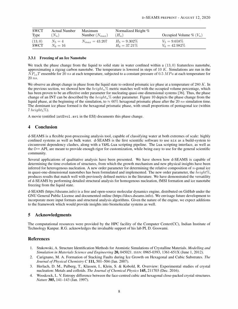
Table 2 summarizes the relative proportions of the n-gonal prism blocks for the SWCTs. Nmax is the same for everyn, and thus the (11,0) and (13,0) SWCTs have Nmax = 63.492% and Nmax = 43.207%, respectively, for all n. It isevident that the normalized height percentage matches reasonably well with the occupied volume percentage.
Table 2: Relative proportions of n-gonal prism blocks
SWCTType
Actual Number(Nn)
MaximumNumber (Nmax)
Normalized Height %(Hn) Occupied Volume % (Vn)
(11, 0)SWCT
N4 = 40 Nmax = 63.627 H4 = 63.492% V4 = 69.611%
7
D-SEAMS PREPRINT - AUGUST 12, 2020
SWCTType
Actual Number(Nn)
MaximumNumber (Nmax)
Normalized Height %(Hn) Occupied Volume % (Vn)
(13, 0)SWCT
N5 = 4N6 = 16
Nmax = 43.207 H5 = 9.302%H6 = 37.21%
V5 = 9.658%V6 = 42.982%
3.3.1 Freezing of an Ice Nanotube
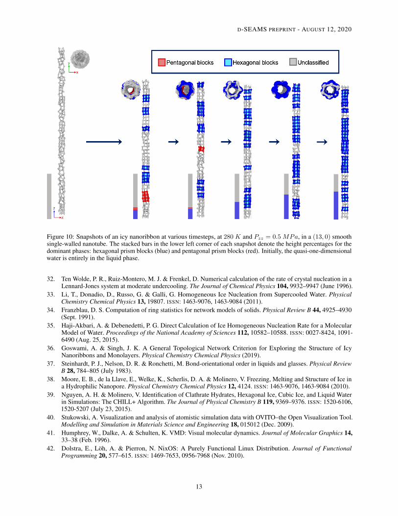
We track the phase change from the liquid to solid state in water confined within a (13, 0) featureless nanotube,approximating a zigzag carbon nanotube. The temperature is lowered in steps of 10 K. Simulations are run in theNPzzT ensemble for 20 ns at each temperature, subjected to a constant pressure of 0.5MPa at each temperature for20 ns.
We observe an abrupt change in phase from the liquid state to ordered prismatic ice phase at a temperature of 280K. Inthe previous section, we showed how the heightn% metric matches well with the occupied volume percentage, whichhas been proven to be an effective order parameter for nucleating quasi-one-dimensional systems [36]. Thus, the phasechange of an INT can be described by the heightn% order parameter. Figure 10 depicts the phase change from theliquid phase, at the beginning of the simulation, to ≈ 60% hexagonal prismatic phase after the 20 ns simulation time.The dominant ice phase formed is the hexagonal prismatic phase, with small proportions of pentagonal ice (within7 height5%).
A movie (entitled intEvol.avi in the ESI) documents this phase change.
4 Conclusion
d-SEAMS is a flexible post-processing analysis tool, capable of classifying water at both extremes of scale: highlyconfined systems as well as bulk water. d-SEAMS is the first scientific software to use nix as a build-system tocircumvent dependency clashes, along with a YAML-Lua scripting pipeline. The Lua scripting interface, as well asthe C++ API, are meant to provide enough rigor for customization, while being easy to use for the general scientificcommunity.
Several applications of qualitative analysis have been presented. We have shown how d-SEAMS is capable ofdetermining the time evolution of structures, from which the growth mechanism and new physical insights have beeninferred for heterogenous nucleation. A new order parameter for determining the relative composition of n-gonal icein quasi-one-dimensional nanotubes has been formulated and implemented. The new order parameter, the height%,produces results that match well with previously defined metrics in the literature. We have demonstrated the versatilityof d-SEAMS by performing detailed structural analysis for homogenous nucleation, fMSI formation and ice nanotubefreezing from the liquid state.
d-SEAMS (https://dseams.info) is a free and open-source molecular dynamics engine, distributed on GitHub under theGNU General Public License and documented online (https://docs.dseams.info). We envisage future development toincorporate more input formats and structural analysis algorithms. Given the nature of the engine, we expect additionsto the framework which would provide insights into biomolecular systems as well.
5 Acknowledgments
The computational resources were provided by the HPC facility of the Computer Center(CC), Indian Institute ofTechnology Kanpur. R.G. acknowledges the invaluable support of his lab PI, D. Goswami.
References
1. Stukowski, A. Structure Identification Methods for Atomistic Simulations of Crystalline Materials. Modelling andSimulation in Materials Science and Engineering 20, 045021. ISSN: 0965-0393, 1361-651X (June 1, 2012).
2. Carignano, M. A. Formation of Stacking Faults during Ice Growth on Hexagonal and Cubic Substrates. TheJournal of Physical Chemistry C 111, 501–504 (Jan. 2007).
3. Herlach, D. M., Palberg, T., Klassen, I., Klein, S. & Kobold, R. Overview: Experimental studies of crystalnucleation: Metals and colloids. The Journal of Chemical Physics 145, 211703 (Dec. 2016).
4. Woodcock, L. V. Entropy difference between the face-centred cubic and hexagonal close-packed crystal structures.Nature 385, 141–143 (Jan. 1997).
8

D-SEAMS PREPRINT - AUGUST 12, 2020
Figure 4: Overhead and side views showing the stacking arrangements of the first two layers of cages on the AgIsurface, when more than half the water has been converted to ice, after more than ≈ 150 ns of simulation time. (a)The first layer is a layer of HCs. The complete second layer is a layer of DDCs in all cases observed. Mixed rings aresandwiched between the first layer of HCs and the second layer of DDCs. (b) The first and second layers are DDCs.The colour scheme is the same as in the preceding figures.
5. Reinhart, W. F., Long, A. W., Howard, M. P., Ferguson, A. L. & Panagiotopoulos, A. Z. Machine learning forautonomous crystal structure identification. Soft Matter 13, 4733–4745 (2017).
6. Lupi, L., Hudait, A. & Molinero, V. Heterogeneous Nucleation of Ice on Carbon Surfaces. Journal of the AmericanChemical Society 136, 3156–3164 (Feb. 2014).
7. Cox, S. J., Kathmann, S. M., Slater, B. & Michaelides, A. Molecular simulations of heterogeneous ice nucleation.I. Controlling ice nucleation through surface hydrophilicity. The Journal of Chemical Physics 142, 184704 (May2015).
8. Bi, Y., Cao, B. & Li, T. Enhanced heterogeneous ice nucleation by special surface geometry. Nature Communica-tions 8 (May 2017).
9. Petrenko, V. & Whitworth, R. Physics of Ice. Oxford Univ 2002.10. Salzmann, C. G., Hallbrucker, A., Finney, J. L. & Mayer, E. Raman spectroscopic study of hydrogen ordered
ice XIII and of its reversible phase transition to disordered ice V. Physical Chemistry Chemical Physics 8, 3088(2006).
11. Salzmann, C. G., Hallbrucker, A., Finney, J. L. & Mayer, E. Raman spectroscopic features of hydrogen-orderingin ice XII. Chemical Physics Letters 429, 469–473 (Oct. 2006).
12. Salzmann, C. G., Radaelli, P. G., Mayer, E. & Finney, J. L. Ice XV: A New Thermodynamically Stable Phase ofIce. Physical Review Letters 103 (Sept. 2009).
13. Falenty, A., Hansen, T. C. & Kuhs, W. F. Formation and properties of ice XVI obtained by emptying a type sIIclathrate hydrate. Nature 516, 231–233 (Dec. 2014).
14. Del Rosso, L., Celli, M. & Ulivi, L. New porous water ice metastable at atmospheric pressure obtained byemptying a hydrogen-filled ice. Nature Communications 7 (Nov. 2016).
15. Algara-Siller, G. et al. Square ice in graphene nanocapillaries. Nature 519, 443–445 (Mar. 2015).16. Agrawal, K. V., Shimizu, S., Drahushuk, L. W., Kilcoyne, D. & Strano, M. S. Observation of extreme phase
transition temperatures of water confined inside isolated carbon nanotubes. Nature Nanotechnology 12, 267–273(Nov. 2016).
17. Zhao, W.-H., Bai, J., Yuan, L.-F., Yang, J. & Zeng, X. C. Ferroelectric hexagonal and rhombic monolayer icephases. Chem. Sci. 5, 1757–1764 (2014).
9
D-SEAMS PREPRINT - AUGUST 12, 2020
Figure 5: Formation of layers of HCs and DDCs within the first 100 ns of simulation time. (a) After ≈ 14 ns, thefirst layer has not completely formed. (b) After ≈ 60 ns, part of the second layer is comprised of HCs, and a separateportion of the second layer is composed of DDCs. The part of the second layer made up of HCs is distinguishable in thetop view because of the AA-stacking order of HCs on the first layer of HCs. (c) After ≈ 100 ns, the second layer isalmost entirely composed of DDCs. The colour scheme is shown in the legend. DDCs are coloured in shades of yellowto vermilion, according to the distance from the AgI surface.
Figure 6: Evolution of an ice crystallite of mW water at 208 GPa in the NPT ensemble. DDCs are in black, HCs are inred and mixed rings belonging to both DDCs and HCs are in green. The number of particles in the largest cluster n isshown for every snapshot of the trajectory. Water molecules which do not participate in the cages are in transparentblue.
10

D-SEAMS PREPRINT - AUGUST 12, 2020
Figure 7: Snapshots of monolayer water being cooled from 320K to 310K, at 1 GPa. The stacked bars in the lowerleft corner of each snapshot denote the coverage area percentages for the 4-membered rings (blue) and 3-memberedrings (red). The colours of the particles, bonds and interior ring shading are shown in the legend.
Figure 8: In-plane oxygen-oxygen radial distribution function of the ice formed at 310K and Pxx = 1 GPa. The insetshows the 4-membered rings characteristic of fMSI.
11
D-SEAMS PREPRINT - AUGUST 12, 2020
Figure 9: View of ice structures at 240K confined within (a) (13, 0) zig-zag nanotube at 0.1MPa and (b) (11, 0) zig-zagnanotube at 1MPa. The unclassified phase, either water or deformed prism blocks, is sea-green. Prism blocks ofpentagonal, hexagonal, and tetragonal ices are shown in purple, blue and pink respectively.
18. Takaiwa, D., Hatano, I., Koga, K. & Tanaka, H. Phase diagram of water in carbon nanotubes. Proceedings of theNational Academy of Sciences 105, 39–43 (Dec. 2007).
19. Bai, J., Angell, C. A. & Zeng, X. C. Guest-free monolayer clathrate and its coexistence with two-dimensionalhigh-density ice. Proceedings of the National Academy of Sciences 107, 5718–5722 (Mar. 2010).
20. Salzmann, C. G., Radaelli, P. G., Slater, B. & Finney, J. L. The polymorphism of ice: five unresolved questions.Physical Chemistry Chemical Physics 13, 18468 (2011).
21. Salzmann, C. G. Advances in the experimental exploration of water’s phase diagram. The Journal of ChemicalPhysics 150, 060901 (Feb. 2019).
22. Chen, J., Schusteritsch, G., Pickard, C. J., Salzmann, C. G. & Michaelides, A. Two Dimensional Ice from FirstPrinciples: Structures and Phase Transitions. Physical Review Letters 116 (Jan. 2016).
23. Koga, K., Tanaka, H. & Zeng, X. C. First-order transition in confined water between high-density liquid andlow-density amorphous phases. Nature 408, 564–567 (Nov. 2000).
24. Zangi, R. & Mark, A. E. Monolayer Ice. Physical Review Letters 91 (July 2003).25. Bai, J. & Zeng, X. C. Polymorphism and polyamorphism in bilayer water confined to slit nanopore under high
pressure. Proceedings of the National Academy of Sciences 109, 21240–21245 (Dec. 2012).26. Zhu, Y., Wang, F., Bai, J., Zeng, X. C. & Wu, H. Compression Limit of Two-Dimensional Water Constrained in
Graphene Nanocapillaries. ACS Nano 9, 12197–12204. ISSN: 1936-0851 (Dec. 22, 2015).27. Zhu, Y., Wang, F., Bai, J., Zeng, X. C. & Wu, H. Formation of Trilayer Ices in Graphene Nanocapillaries under
High Lateral Pressure. The Journal of Physical Chemistry C 120, 8109–8115 (Apr. 2016).28. Gao, Z., Giovambattista, N. & Sahin, O. Phase Diagram of Water Confined by Graphene. Sci Rep 8, 1–11. ISSN:
2045-2322 (Apr. 18, 2018).29. Boettiger, C. An introduction to Docker for reproducible research. ACM SIGOPS Operating Systems Review 49,
71–79 (Jan. 2015).30. Dolstra, E., de Jonge, M. & Visser, E. Nix: A Safe and Policy-Free System for Software Deployment, 15 (2004).31. Prins, J., Suresh, J. & Dolstra, E. Nix fixes depency hell on all Linux distributions in Linux (2008).
12
D-SEAMS PREPRINT - AUGUST 12, 2020
Figure 10: Snapshots of an icy nanoribbon at various timesteps, at 280 K and Pzz = 0.5MPa, in a (13, 0) smoothsingle-walled nanotube. The stacked bars in the lower left corner of each snapshot denote the height percentages for thedominant phases: hexagonal prism blocks (blue) and pentagonal prism blocks (red). Initially, the quasi-one-dimensionalwater is entirely in the liquid phase.
32. Ten Wolde, P. R., Ruiz-Montero, M. J. & Frenkel, D. Numerical calculation of the rate of crystal nucleation in aLennard-Jones system at moderate undercooling. The Journal of Chemical Physics 104, 9932–9947 (June 1996).
33. Li, T., Donadio, D., Russo, G. & Galli, G. Homogeneous Ice Nucleation from Supercooled Water. PhysicalChemistry Chemical Physics 13, 19807. ISSN: 1463-9076, 1463-9084 (2011).
34. Franzblau, D. S. Computation of ring statistics for network models of solids. Physical Review B 44, 4925–4930(Sept. 1991).
35. Haji-Akbari, A. & Debenedetti, P. G. Direct Calculation of Ice Homogeneous Nucleation Rate for a MolecularModel of Water. Proceedings of the National Academy of Sciences 112, 10582–10588. ISSN: 0027-8424, 1091-6490 (Aug. 25, 2015).
36. Goswami, A. & Singh, J. K. A General Topological Network Criterion for Exploring the Structure of IcyNanoribbons and Monolayers. Physical Chemistry Chemical Physics (2019).
37. Steinhardt, P. J., Nelson, D. R. & Ronchetti, M. Bond-orientational order in liquids and glasses. Physical ReviewB 28, 784–805 (July 1983).
38. Moore, E. B., de la Llave, E., Welke, K., Scherlis, D. A. & Molinero, V. Freezing, Melting and Structure of Ice ina Hydrophilic Nanopore. Physical Chemistry Chemical Physics 12, 4124. ISSN: 1463-9076, 1463-9084 (2010).
39. Nguyen, A. H. & Molinero, V. Identification of Clathrate Hydrates, Hexagonal Ice, Cubic Ice, and Liquid Waterin Simulations: The CHILL+ Algorithm. The Journal of Physical Chemistry B 119, 9369–9376. ISSN: 1520-6106,1520-5207 (July 23, 2015).
40. Stukowski, A. Visualization and analysis of atomistic simulation data with OVITO–the Open Visualization Tool.Modelling and Simulation in Materials Science and Engineering 18, 015012 (Dec. 2009).
41. Humphrey, W., Dalke, A. & Schulten, K. VMD: Visual molecular dynamics. Journal of Molecular Graphics 14,33–38 (Feb. 1996).
42. Dolstra, E., Löh, A. & Pierron, N. NixOS: A Purely Functional Linux Distribution. Journal of FunctionalProgramming 20, 577–615. ISSN: 1469-7653, 0956-7968 (Nov. 2010).
13
D-SEAMS PREPRINT - AUGUST 12, 2020
43. Peng, R. D. Reproducible Research in Computational Science. Science 334, 1226–1227. ISSN: 0036-8075,1095-9203 (Dec. 2, 2011).
44. Shirts, M. R. et al. Lessons learned from comparing molecular dynamics engines on the SAMPL5 dataset. Journalof Computer-Aided Molecular Design 31, 147–161 (Oct. 2016).
45. Stoddard, S. D. Identifying clusters in computer experiments on systems of particles. Journal of ComputationalPhysics 27, 291–293 (May 1978).
46. Vonnegut, B. The Nucleation of Ice Formation by Silver Iodide. Journal of Applied Physics 18, 593–595 (July1947).
47. Zielke, S. A., Bertram, A. K. & Patey, G. N. A Molecular Mechanism of Ice Nucleation on Model AgI Surfaces.The Journal of Physical Chemistry B 119, 9049–9055 (Oct. 2014).
48. Abascal, J. L. F., Sanz, E., Fernández, R. G. & Vega, C. A potential model for the study of ices and amorphouswater: TIP4P/Ice. The Journal of Chemical Physics 122, 234511 (June 2005).
49. Prerna, Goswami, R., Metya, A. K., Shevkunov, S. V. & Singh, J. K. Study of Ice Nucleation on Silver IodideSurface with Defects. Molecular Physics, 1–13. ISSN: 0026-8976, 1362-3028 (Aug. 25, 2019).
50. Zielke, S. A., Bertram, A. K. & Patey, G. N. Simulations of Ice Nucleation by Model AgI Disks and Plates. TheJournal of Physical Chemistry B 120, 2291–2299 (Feb. 2016).
51. Molinero, V. & Moore, E. B. Water Modeled As an Intermediate Element between Carbon and Silicon†. TheJournal of Physical Chemistry B 113, 4008–4016 (Apr. 2009).
52. Yang, L., Guo, Y. & Diao, D. Structure and dynamics of water confined in a graphene nanochannel undergigapascal high pressure: dependence of friction on pressure and confinement. Physical Chemistry ChemicalPhysics 19, 14048–14054 (2017).
14
Supporting information for:
d-SEAMS: Deferred Structural Elucidation
Analysis for Molecular Simulations
Rohit Goswami,†,†,¶ Amrita Goswami,‡,¶ and Jayant K. Singh∗,‡
†Currently at the Department of Chemistry, Indian Institute of Technology Kanpur
‡Department of Chemical Engineering, Indian Institute of Technology Kanpur
¶Contributed equally to this work
E-mail: [email protected]
Design
The d-SEAMS framework is designed to be accessible to the end-user, while offering a pow-
erful system of building blocks and generics for extensions. The engine itself is written in C++
and is compiled to a binary. This binary accepts Lua input scripts to expose the functionality
of the software such that the underlying data-structures and computations are abstracted
away from the user. To facilitate reproduction of results and to prevent users from access-
ing conflicting or unphysical functional manipulations of the input data, YAML options mask
certain functions from being exposed. The YAML workflows are completely reproducible in
Lua scripts, but provide an easy way to share methodologies and also reduces the cognitive
load of going through the complete API documentation.
S1
arX
iv:1
909.
0983
0v3
[ph
ysic
s.co
mp-
ph]
13
Jan
2020

Figure S1: Work-flow of d-SEAMS. ‘Nix‘ uses cryptographic hashes to ensure reproduciblebuilds over all systems. ‘Cmake‘ compiles and builds the source code, using the dependenciesmanaged by ‘nix‘. The ‘Lua‘ script provides an interface to the back-end functions. Combi-nations of these ‘C++‘ functions can be called the ’meta’ functions. The ‘YAML‘ interfaceexposes only relevant back-end and ‘Lua‘ functions, corresponding to the user-determinedpre-determined work-flow.
Figure S1 is a schematic of the overall design architecture of d-SEAMS. The Lua script-
ing interface exposes C-like functions to create custom work-flows. The YAML configuration
file provides options for pre-determined work-flows. Users with different requirements and
experience can interact with d-SEAMS. The three main components of the code architecture
are enumerated below:
• YAML configuration file: This contains options for pre-determined work-flows. For
example, a user who enters the option for the confined quasi-one-dimensional ice deter-
mination will only be exposed to the relevant functions for INT prism determination.
Multiple workflows can be selected at the same time.
• Lua Interface: C++ functions are registered as Lua functions, which are called from
a Lua script. Lua is a C-like scripting language, enabling users to call the Lua functions
without needing to learn a software-specific scripting convention. The advantage of
S2
using Lua over directly calling C++ functions is that the users need not be concerned
with pointers and clean-up of the C++ structures. The Lua language also has a rich set
of cross platform extensions for file handling, and is also supported by major editors
for syntax highlighting.
• C++ Back-end: The back-end is written in modern C++, employing common data
structures, used uniformly throughout the code. Users can easily extend and write their
own C++ header files, and the documentation covers manipulating the build system to
accept both user-defined and external headers. Registering custom C++ functions as
Lua functions, to be subsequently called in Lua scripts, is also documented. GDBS1 can
be used for code debugging, since the back-end is in C++.
From a user perspective, we have designed the Lua functions to mimic the mindset
of a computational chemist, without burdening them with the software implementation.
We have also ensured reproducibility, both as an aid to the scienceS2 intended and also
to allow for bugs to be dealt with more efficiently. This reproducibility is ensured during
build, compile, and linking stages, by leveraging the functional, immutable binaries produced
by nix.S3 The dependencies are handled reproducibly, though for ease of extension by the
wider community, most of the build system is in CMake. We use nix to ensure that the
dependencies of the binary are fully reproducible, as a consequence of traversing the build
graph defined by the nix-derivation. The binary itself has a server-client architecture, to
ensure that the user can transparently interact with the code without needing a background
in functional programming. Since the backend server is written entirely in modern C++,
the GDB debugger is usable throughout. The server-client nature of the system, though
currently a bottleneck in terms of parallelism, allows for a single compiled binary to be used
for the execution of multiple different Lua input scripts, with each script spawning a separate
process.
S3
Nix
The nix derivation provides a deterministic package-level lock on all dependencies and is
written in nix, a lazy, dynamically typed, purely functional language.S4 This choice of dis-
tribution also allows the user to extend the system reproducibly, ensuring that changes can
be quickly merged in-to the upstream repository. More details of the ‘nix‘-build system are
described in the main text of the manuscript.
Lua
Existing molecular dynamics packages suffer from not having design parameters built-in, and
with time, this has led to unique and non-standard syntax being used, as seen in the input
scripts of LAMMPSS5 and GROMACS,S6 amongst others. Popular text editors do not offer
syntax highlighting for these custom non-standard and software-specific syntaxes. For such
software-specific syntaxes, the code is unusable without learning from the documentation.
An alternative to crafting a new input script syntax for each software, is to use python for
scripting.S7 However, the version dependence of each internal segment can become intractable
without continuous development, and as a result, these spawn multiple language-specific
errors, and they work best only on the Linux distribution on which the creators have worked
. Furthermore, we assert that the proliferation of python scripts and the odd-ease at which
they may be, in theory mixed and matched, in practice causes many clashes, for example,
EsPreSSoS8 and Quantum EsPreSSoS9 (and more generally, ScipyS10 and NumpyS11) have
several function names in common which cause difficult to debug when used together in an
input script. Also, python has less support for debugging, and the language server support is
lacking, making complex python code difficult to debug. This is partially due to the design
of python itself. The lack of static typing has the effect of making the compiler oblivious to
bugs which are caught easily in statically typed languages like FORTRAN and C++.
To address these concerns we have opted to use Lua as the scripting interface, which
has C-like functions. It is widely supported in terms of syntax highlighting, and is easy to
S4
interface with C++ code. Furthermore, the error handling is such that it is amenable for
arbitrarily complex GDB debugger workflows,S12 and the rich standard library of Lua, along
with user extensions, have no clashes. Lua is also user friendly due to its C-like syntax. The
rich table and object handling makes writing out image data easy. Furthermore, though Lua
was released two years after python was first introduced (1993 and 1991, respectively) unlike
python, which is still transitioning from the major API change of two to three, the Lua
API is stable, mostly because it has been designed to be an embedded language and not a
general-purpose language like python. Lua has been the darling of the gaming development
community, and has proven its worth in many related domains such as image handling.
Apart from the user-friendly helper functions, our design has the Lua interface, which offers
every core function to the user. This permits arbitarily complicated workflows to be used
without re-compiliation, which is a boon for HPC cluster usage. We recommend strongly in
the docs, that foreign code, once interfaced to the C++ engine, should be bound in Lua for
the end-users as well.
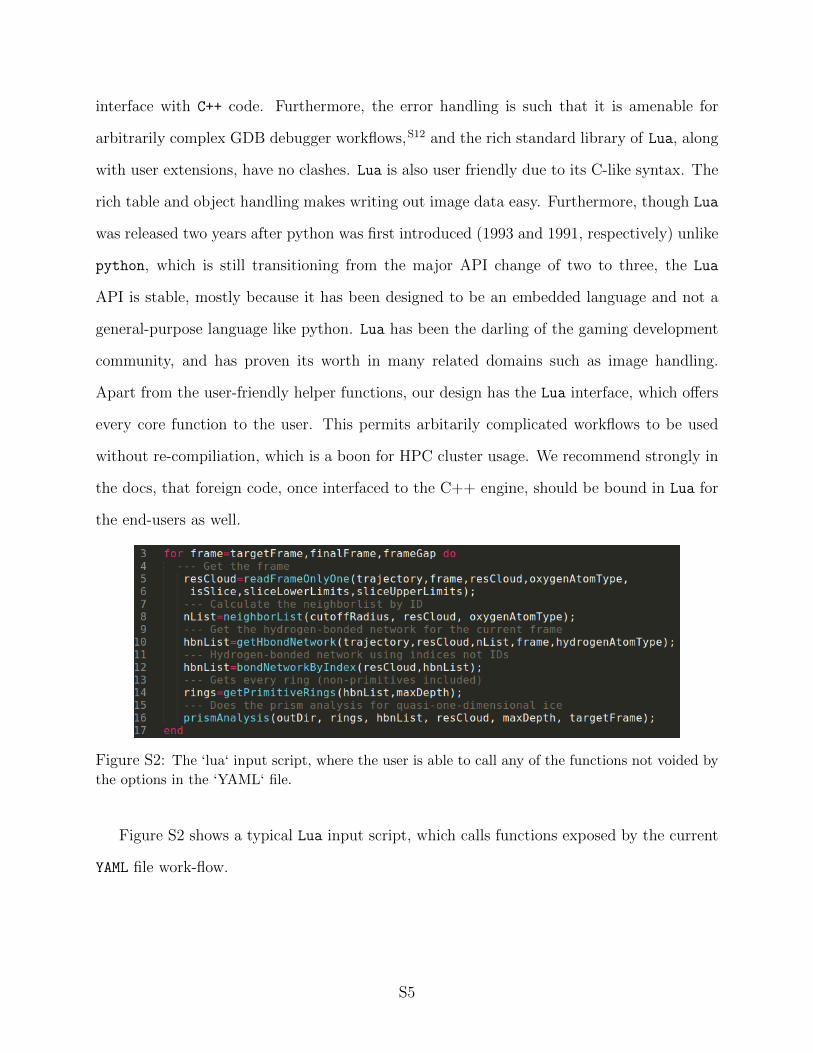
Figure S2: The ‘lua‘ input script, where the user is able to call any of the functions not voided by
the options in the ‘YAML‘ file.
Figure S2 shows a typical Lua input script, which calls functions exposed by the current
YAML file work-flow.
S5
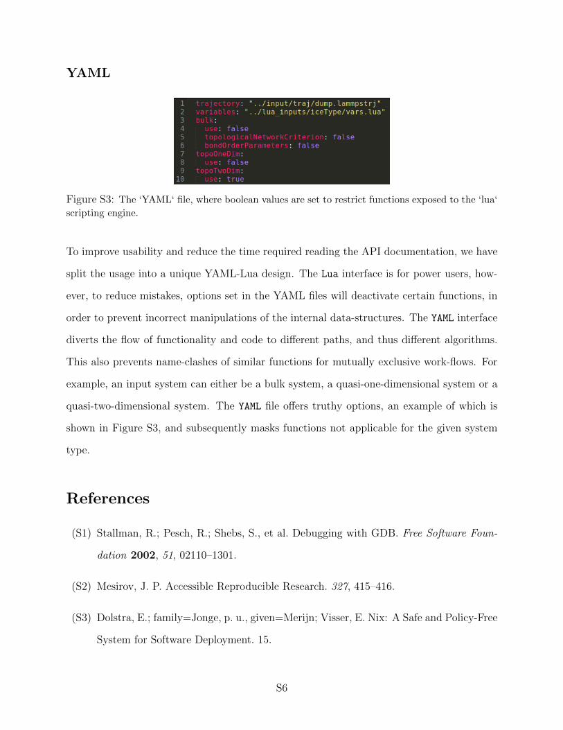
YAML
Figure S3: The ‘YAML‘ file, where boolean values are set to restrict functions exposed to the ‘lua‘
scripting engine.
To improve usability and reduce the time required reading the API documentation, we have
split the usage into a unique YAML-Lua design. The Lua interface is for power users, how-
ever, to reduce mistakes, options set in the YAML files will deactivate certain functions, in
order to prevent incorrect manipulations of the internal data-structures. The YAML interface
diverts the flow of functionality and code to different paths, and thus different algorithms.
This also prevents name-clashes of similar functions for mutually exclusive work-flows. For
example, an input system can either be a bulk system, a quasi-one-dimensional system or a
quasi-two-dimensional system. The YAML file offers truthy options, an example of which is
shown in Figure S3, and subsequently masks functions not applicable for the given system
type.
References
(S1) Stallman, R.; Pesch, R.; Shebs, S., et al. Debugging with GDB. Free Software Foun-
dation 2002, 51, 02110–1301.
(S2) Mesirov, J. P. Accessible Reproducible Research. 327, 415–416.
(S3) Dolstra, E.; family=Jonge, p. u., given=Merijn; Visser, E. Nix: A Safe and Policy-Free
System for Software Deployment. 15.
S6

(S4) Dolstra, E.; Lh, A.; Pierron, N. NixOS: A Purely Functional Linux Distribution. 20,
577–615.
(S5) Plimpton, S. Fast Parallel Algorithms for ShortRange Molecular Dynamics. 42.
(S6) Abraham, M. J.; Murtola, T.; Schulz, R.; Pll, S.; Smith, J. C.; Hess, B.; Lindahl, E.
GROMACS: High Performance Molecular Simulations through Multi-Level Paral-
lelism from Laptops to Supercomputers. 1-2, 19–25.
(S7) McGibbon, R. T.; Beauchamp, K. A.; Harrigan, M. P.; Klein, C.; Swails, J. M.;
Hernndez, C. X.; Schwantes, C. R.; Wang, L.-P.; Lane, T. J.; Pande, V. S. MDTraj:
A Modern Open Library for the Analysis of Molecular Dynamics Trajectories. 109,
1528–1532.
(S8) Weik, F.; Weeber, R.; Szuttor, K.; Breitsprecher, K.; fam-
ily=Graaf, p. u., given=Joost; Kuron, M.; Landsgesell, J.; Menke, H.; Sean, D.;
Holm, C. ESPResSo 4.0 an Extensible Software Package for Simulating Soft Matter
Systems. 227, 1789–1816.
(S9) Giannozzi, P.; Baroni, S.; Bonini, N.; Calandra, M.; Car, R.; Cavazzoni, C.;
Ceresoli, D.; Chiarotti, G. L.; Cococcioni, M.; Dabo, I.; Corso, A. D.; fam-
ily=Gironcoli, p. u., given=Stefano; Fabris, S.; Fratesi, G.; Gebauer, R.; Gerst-
mann, U.; Gougoussis, C.; Kokalj, A.; Lazzeri, M.; Martin-Samos, L.; Marzari, N.;
Mauri, F.; Mazzarello, R.; Paolini, S.; Pasquarello, A.; Paulatto, L.; Sbraccia, C.;
Scandolo, S.; Sclauzero, G.; Seitsonen, A. P.; Smogunov, A.; Umari, P.; Wentzcov-
itch, R. M. QUANTUM ESPRESSO: A Modular and Open-Source Software Project
for Quantum Simulations of Materials. 21, 395502.
(S10) Oliphant, T. E. Python for Scientific Computing. 9, 10–20.
(S11) family=Walt, p. d. u., given=S.; Colbert, S. C.; Varoquaux, G. The NumPy Array:
A Structure for Efficient Numerical Computation. 13, 22–30.
S7

(S12) Stallman, R.; Pesch, R.; Shebs, S. Debugging with GDB. 352.
S8