D Dräger Polytron IR type 334 and type 340 - Draeger Web App · Dräger Polytron ® IR type 334...
76
D Dräger Polytron IR type 334 and type 340 Infrared Gas Transmitter (approved as Polytron 2 IR Ausf./Style 334 and 340) Instructions for Use ST–3836–2003.eps
-
Upload
nguyendien -
Category
Documents
-
view
363 -
download
24
Transcript of D Dräger Polytron IR type 334 and type 340 - Draeger Web App · Dräger Polytron ® IR type 334...

D
Dräger Polytron IR type 334 and type 340
Infrared Gas Transmitter(approved as Polytron 2 IR Ausf./Style 334 and 340)
Instructions for Use
ST–
38
36
–2
00
3.e
ps

Contents
2
Contents
For Your Safety
. . . . . . . . . . . . . . . . . . . . . . . . . . . . . . . . . . . . . . . . . . . . . . . . . . . . . . . . . . . . . . . . . . . . . . . . . . . . . . . . . . . . . . . . . . . . . . 4
Intended use
. . . . . . . . . . . . . . . . . . . . . . . . . . . . . . . . . . . . . . . . . . . . . . . . . . . . . . . . . . . . . . . . . . . . . . . . . . . . . . . . . . . . . . . . . . . . . . . . 5
Approval for use in hazardous areas
. . . . . . . . . . . . . . . . . . . . . . . . . . . . . . . . . . . . . . . . . . . . . . . . . . . . . . . . . . . . . . . . . . . . . . . . . . . 5
Installation of the gas transmitter
. . . . . . . . . . . . . . . . . . . . . . . . . . . . . . . . . . . . . . . . . . . . . . . . . . . . . . . . . . . . . . . . . . . . . . . . . . . . . 6Installation site . . . . . . . . . . . . . . . . . . . . . . . . . . . . . . . . . . . . . . . . . . . . . . . . . . . . . . . . . . . . . . . . . . . . . . . . . . . . . . . . . . . . . . . . . . . . . . . . 6Mechanical installation . . . . . . . . . . . . . . . . . . . . . . . . . . . . . . . . . . . . . . . . . . . . . . . . . . . . . . . . . . . . . . . . . . . . . . . . . . . . . . . . . . . . . . . . . 7Electrical installation . . . . . . . . . . . . . . . . . . . . . . . . . . . . . . . . . . . . . . . . . . . . . . . . . . . . . . . . . . . . . . . . . . . . . . . . . . . . . . . . . . . . . . . . . . . 8Installation of the accessories . . . . . . . . . . . . . . . . . . . . . . . . . . . . . . . . . . . . . . . . . . . . . . . . . . . . . . . . . . . . . . . . . . . . . . . . . . . . . . . . . . 10
Operation
. . . . . . . . . . . . . . . . . . . . . . . . . . . . . . . . . . . . . . . . . . . . . . . . . . . . . . . . . . . . . . . . . . . . . . . . . . . . . . . . . . . . . . . . . . . . . . . . . . 13System start-up . . . . . . . . . . . . . . . . . . . . . . . . . . . . . . . . . . . . . . . . . . . . . . . . . . . . . . . . . . . . . . . . . . . . . . . . . . . . . . . . . . . . . . . . . . . . . . . 13Configuring the gas transmitter . . . . . . . . . . . . . . . . . . . . . . . . . . . . . . . . . . . . . . . . . . . . . . . . . . . . . . . . . . . . . . . . . . . . . . . . . . . . . . . . . 14Measurement . . . . . . . . . . . . . . . . . . . . . . . . . . . . . . . . . . . . . . . . . . . . . . . . . . . . . . . . . . . . . . . . . . . . . . . . . . . . . . . . . . . . . . . . . . . . . . . . 16
Maintenance
. . . . . . . . . . . . . . . . . . . . . . . . . . . . . . . . . . . . . . . . . . . . . . . . . . . . . . . . . . . . . . . . . . . . . . . . . . . . . . . . . . . . . . . . . . . . . . . 17Maintenance intervals . . . . . . . . . . . . . . . . . . . . . . . . . . . . . . . . . . . . . . . . . . . . . . . . . . . . . . . . . . . . . . . . . . . . . . . . . . . . . . . . . . . . . . . . . 17Checking and if necessary cleaning the cuvette in the gas transmitter . . . . . . . . . . . . . . . . . . . . . . . . . . . . . . . . . . . . . . . . . . . . . . . . 18
Fault, cause, remedy
. . . . . . . . . . . . . . . . . . . . . . . . . . . . . . . . . . . . . . . . . . . . . . . . . . . . . . . . . . . . . . . . . . . . . . . . . . . . . . . . . . . . . . . . 19
Method of operation
. . . . . . . . . . . . . . . . . . . . . . . . . . . . . . . . . . . . . . . . . . . . . . . . . . . . . . . . . . . . . . . . . . . . . . . . . . . . . . . . . . . . . . . . 20Connecting the hand terminal ABB 691 HT . . . . . . . . . . . . . . . . . . . . . . . . . . . . . . . . . . . . . . . . . . . . . . . . . . . . . . . . . . . . . . . . . . . . . . 20Switching on the hand terminal . . . . . . . . . . . . . . . . . . . . . . . . . . . . . . . . . . . . . . . . . . . . . . . . . . . . . . . . . . . . . . . . . . . . . . . . . . . . . . . . . 20Switching off the hand terminal . . . . . . . . . . . . . . . . . . . . . . . . . . . . . . . . . . . . . . . . . . . . . . . . . . . . . . . . . . . . . . . . . . . . . . . . . . . . . . . . . 20Linking up with the gas transmitter . . . . . . . . . . . . . . . . . . . . . . . . . . . . . . . . . . . . . . . . . . . . . . . . . . . . . . . . . . . . . . . . . . . . . . . . . . . . . . 21Menu structure . . . . . . . . . . . . . . . . . . . . . . . . . . . . . . . . . . . . . . . . . . . . . . . . . . . . . . . . . . . . . . . . . . . . . . . . . . . . . . . . . . . . . . . . . . . . . . . 21
"PV" menu (Dynamic Var)
. . . . . . . . . . . . . . . . . . . . . . . . . . . . . . . . . . . . . . . . . . . . . . . . . . . . . . . . . . . . . . . . . . . . . . . . . . . . . . . . . . . . 23MEASUREMENT TYPE . . . . . . . . . . . . . . . . . . . . . . . . . . . . . . . . . . . . . . . . . . . . . . . . . . . . . . . . . . . . . . . . . . . . . . . . . . . . . . . . . . . . . . . 23ON LINE INFO . . . . . . . . . . . . . . . . . . . . . . . . . . . . . . . . . . . . . . . . . . . . . . . . . . . . . . . . . . . . . . . . . . . . . . . . . . . . . . . . . . . . . . . . . . . . . . . 23
"REVIEW" menu
. . . . . . . . . . . . . . . . . . . . . . . . . . . . . . . . . . . . . . . . . . . . . . . . . . . . . . . . . . . . . . . . . . . . . . . . . . . . . . . . . . . . . . . . . . . . 24DIAGNOSTIC . . . . . . . . . . . . . . . . . . . . . . . . . . . . . . . . . . . . . . . . . . . . . . . . . . . . . . . . . . . . . . . . . . . . . . . . . . . . . . . . . . . . . . . . . . . . . . . 24
FAULTS . . . . . . . . . . . . . . . . . . . . . . . . . . . . . . . . . . . . . . . . . . . . . . . . . . . . . . . . . . . . . . . . . . . . . . . . . . . . . . . . . . . . . . . . . . . . . . . . 24WARNINGS . . . . . . . . . . . . . . . . . . . . . . . . . . . . . . . . . . . . . . . . . . . . . . . . . . . . . . . . . . . . . . . . . . . . . . . . . . . . . . . . . . . . . . . . . . . . . 25SENSOR TEMPERATURE . . . . . . . . . . . . . . . . . . . . . . . . . . . . . . . . . . . . . . . . . . . . . . . . . . . . . . . . . . . . . . . . . . . . . . . . . . . . . . . . 25ERROR BUFFER (error values in HEX code) . . . . . . . . . . . . . . . . . . . . . . . . . . . . . . . . . . . . . . . . . . . . . . . . . . . . . . . . . . . . . . . . . 25
TRANSMITTER INFO . . . . . . . . . . . . . . . . . . . . . . . . . . . . . . . . . . . . . . . . . . . . . . . . . . . . . . . . . . . . . . . . . . . . . . . . . . . . . . . . . . . . . . . . . 26HW Part Number . . . . . . . . . . . . . . . . . . . . . . . . . . . . . . . . . . . . . . . . . . . . . . . . . . . . . . . . . . . . . . . . . . . . . . . . . . . . . . . . . . . . . . . . . 26HW Serial Number . . . . . . . . . . . . . . . . . . . . . . . . . . . . . . . . . . . . . . . . . . . . . . . . . . . . . . . . . . . . . . . . . . . . . . . . . . . . . . . . . . . . . . . 26SW Part Number . . . . . . . . . . . . . . . . . . . . . . . . . . . . . . . . . . . . . . . . . . . . . . . . . . . . . . . . . . . . . . . . . . . . . . . . . . . . . . . . . . . . . . . . . 26SW Version . . . . . . . . . . . . . . . . . . . . . . . . . . . . . . . . . . . . . . . . . . . . . . . . . . . . . . . . . . . . . . . . . . . . . . . . . . . . . . . . . . . . . . . . . . . . . 26
"CONFIGURATION" menu
. . . . . . . . . . . . . . . . . . . . . . . . . . . . . . . . . . . . . . . . . . . . . . . . . . . . . . . . . . . . . . . . . . . . . . . . . . . . . . . . . . . . 27INITIALIZATION . . . . . . . . . . . . . . . . . . . . . . . . . . . . . . . . . . . . . . . . . . . . . . . . . . . . . . . . . . . . . . . . . . . . . . . . . . . . . . . . . . . . . . . . . . . . . . 28
Initialization procedure: . . . . . . . . . . . . . . . . . . . . . . . . . . . . . . . . . . . . . . . . . . . . . . . . . . . . . . . . . . . . . . . . . . . . . . . . . . . . . . . . . . . 28SET CATEGORY . . . . . . . . . . . . . . . . . . . . . . . . . . . . . . . . . . . . . . . . . . . . . . . . . . . . . . . . . . . . . . . . . . . . . . . . . . . . . . . . . . . . . . . . . . . . . 29GAS + RANGE . . . . . . . . . . . . . . . . . . . . . . . . . . . . . . . . . . . . . . . . . . . . . . . . . . . . . . . . . . . . . . . . . . . . . . . . . . . . . . . . . . . . . . . . . . . . . . 30
Select type of gas . . . . . . . . . . . . . . . . . . . . . . . . . . . . . . . . . . . . . . . . . . . . . . . . . . . . . . . . . . . . . . . . . . . . . . . . . . . . . . . . . . . . . . . . 30Select unit of measurement . . . . . . . . . . . . . . . . . . . . . . . . . . . . . . . . . . . . . . . . . . . . . . . . . . . . . . . . . . . . . . . . . . . . . . . . . . . . . . . . 30Select unit of measurement . . . . . . . . . . . . . . . . . . . . . . . . . . . . . . . . . . . . . . . . . . . . . . . . . . . . . . . . . . . . . . . . . . . . . . . . . . . . . . . . 30
3
Contents
CALIBRATION PARAM. . . . . . . . . . . . . . . . . . . . . . . . . . . . . . . . . . . . . . . . . . . . . . . . . . . . . . . . . . . . . . . . . . . . . . . . . . . . . . . . . . . . . . . 31Select type of calibration gas . . . . . . . . . . . . . . . . . . . . . . . . . . . . . . . . . . . . . . . . . . . . . . . . . . . . . . . . . . . . . . . . . . . . . . . . . . . . . . . 31Select calibration gas unit . . . . . . . . . . . . . . . . . . . . . . . . . . . . . . . . . . . . . . . . . . . . . . . . . . . . . . . . . . . . . . . . . . . . . . . . . . . . . . . . . . 31
SPECIAL SIGNAL . . . . . . . . . . . . . . . . . . . . . . . . . . . . . . . . . . . . . . . . . . . . . . . . . . . . . . . . . . . . . . . . . . . . . . . . . . . . . . . . . . . . . . . . . . . 32WARNING ON/OFF . . . . . . . . . . . . . . . . . . . . . . . . . . . . . . . . . . . . . . . . . . . . . . . . . . . . . . . . . . . . . . . . . . . . . . . . . . . . . . . . . . . . . . 32WARNING LEVEL . . . . . . . . . . . . . . . . . . . . . . . . . . . . . . . . . . . . . . . . . . . . . . . . . . . . . . . . . . . . . . . . . . . . . . . . . . . . . . . . . . . . . . . . 33BEAM BLOCK . . . . . . . . . . . . . . . . . . . . . . . . . . . . . . . . . . . . . . . . . . . . . . . . . . . . . . . . . . . . . . . . . . . . . . . . . . . . . . . . . . . . . . . . . . . 34– BEAM BLOCK LEVEL . . . . . . . . . . . . . . . . . . . . . . . . . . . . . . . . . . . . . . . . . . . . . . . . . . . . . . . . . . . . . . . . . . . . . . . . . . . . . . . . . . 34MAINTENANCE LEVEL . . . . . . . . . . . . . . . . . . . . . . . . . . . . . . . . . . . . . . . . . . . . . . . . . . . . . . . . . . . . . . . . . . . . . . . . . . . . . . . . . . . 35
COMMUNICATION . . . . . . . . . . . . . . . . . . . . . . . . . . . . . . . . . . . . . . . . . . . . . . . . . . . . . . . . . . . . . . . . . . . . . . . . . . . . . . . . . . . . . . . . . . 36POLLING ADDRESS . . . . . . . . . . . . . . . . . . . . . . . . . . . . . . . . . . . . . . . . . . . . . . . . . . . . . . . . . . . . . . . . . . . . . . . . . . . . . . . . . . . . . 36UNIQUE IDENTIFIER . . . . . . . . . . . . . . . . . . . . . . . . . . . . . . . . . . . . . . . . . . . . . . . . . . . . . . . . . . . . . . . . . . . . . . . . . . . . . . . . . . . . . 37TAG . . . . . . . . . . . . . . . . . . . . . . . . . . . . . . . . . . . . . . . . . . . . . . . . . . . . . . . . . . . . . . . . . . . . . . . . . . . . . . . . . . . . . . . . . . . . . . . . . . . . 37
"Trim" menu
. . . . . . . . . . . . . . . . . . . . . . . . . . . . . . . . . . . . . . . . . . . . . . . . . . . . . . . . . . . . . . . . . . . . . . . . . . . . . . . . . . . . . . . . . . . . . . . . 38CALIBRATE SENSOR . . . . . . . . . . . . . . . . . . . . . . . . . . . . . . . . . . . . . . . . . . . . . . . . . . . . . . . . . . . . . . . . . . . . . . . . . . . . . . . . . . . . . . . . 38
ZERO . . . . . . . . . . . . . . . . . . . . . . . . . . . . . . . . . . . . . . . . . . . . . . . . . . . . . . . . . . . . . . . . . . . . . . . . . . . . . . . . . . . . . . . . . . . . . . . . . . . 39SPAN . . . . . . . . . . . . . . . . . . . . . . . . . . . . . . . . . . . . . . . . . . . . . . . . . . . . . . . . . . . . . . . . . . . . . . . . . . . . . . . . . . . . . . . . . . . . . . . . . . . 40
SET ANALOG . . . . . . . . . . . . . . . . . . . . . . . . . . . . . . . . . . . . . . . . . . . . . . . . . . . . . . . . . . . . . . . . . . . . . . . . . . . . . . . . . . . . . . . . . . . . . . . 42SET 1 – 22 mA . . . . . . . . . . . . . . . . . . . . . . . . . . . . . . . . . . . . . . . . . . . . . . . . . . . . . . . . . . . . . . . . . . . . . . . . . . . . . . . . . . . . . . . . . . . 42TESTING . . . . . . . . . . . . . . . . . . . . . . . . . . . . . . . . . . . . . . . . . . . . . . . . . . . . . . . . . . . . . . . . . . . . . . . . . . . . . . . . . . . . . . . . . . . . . . . . 43– WARNING . . . . . . . . . . . . . . . . . . . . . . . . . . . . . . . . . . . . . . . . . . . . . . . . . . . . . . . . . . . . . . . . . . . . . . . . . . . . . . . . . . . . . . . . . . . . 44– FAULT . . . . . . . . . . . . . . . . . . . . . . . . . . . . . . . . . . . . . . . . . . . . . . . . . . . . . . . . . . . . . . . . . . . . . . . . . . . . . . . . . . . . . . . . . . . . . . . . 44– BEAM BLOCK . . . . . . . . . . . . . . . . . . . . . . . . . . . . . . . . . . . . . . . . . . . . . . . . . . . . . . . . . . . . . . . . . . . . . . . . . . . . . . . . . . . . . . . . . 44– MAINTENACE . . . . . . . . . . . . . . . . . . . . . . . . . . . . . . . . . . . . . . . . . . . . . . . . . . . . . . . . . . . . . . . . . . . . . . . . . . . . . . . . . . . . . . . . . 44
CALIBRATE ANALOG . . . . . . . . . . . . . . . . . . . . . . . . . . . . . . . . . . . . . . . . . . . . . . . . . . . . . . . . . . . . . . . . . . . . . . . . . . . . . . . . . . . . . . . . 454 mA . . . . . . . . . . . . . . . . . . . . . . . . . . . . . . . . . . . . . . . . . . . . . . . . . . . . . . . . . . . . . . . . . . . . . . . . . . . . . . . . . . . . . . . . . . . . . . . . . . . . 4520 mA . . . . . . . . . . . . . . . . . . . . . . . . . . . . . . . . . . . . . . . . . . . . . . . . . . . . . . . . . . . . . . . . . . . . . . . . . . . . . . . . . . . . . . . . . . . . . . . . . . . 46
Technical data
. . . . . . . . . . . . . . . . . . . . . . . . . . . . . . . . . . . . . . . . . . . . . . . . . . . . . . . . . . . . . . . . . . . . . . . . . . . . . . . . . . . . . . . . . . . . . . 47Cross-sensitivities, type 334 . . . . . . . . . . . . . . . . . . . . . . . . . . . . . . . . . . . . . . . . . . . . . . . . . . . . . . . . . . . . . . . . . . . . . . . . . . . . . . . . . . . 50Cross-sensitivities, type 340 . . . . . . . . . . . . . . . . . . . . . . . . . . . . . . . . . . . . . . . . . . . . . . . . . . . . . . . . . . . . . . . . . . . . . . . . . . . . . . . . . . . 51Dimensions . . . . . . . . . . . . . . . . . . . . . . . . . . . . . . . . . . . . . . . . . . . . . . . . . . . . . . . . . . . . . . . . . . . . . . . . . . . . . . . . . . . . . . . . . . . . . . . . . 52
Design and principle of operation
. . . . . . . . . . . . . . . . . . . . . . . . . . . . . . . . . . . . . . . . . . . . . . . . . . . . . . . . . . . . . . . . . . . . . . . . . . . . . 53
Order list
. . . . . . . . . . . . . . . . . . . . . . . . . . . . . . . . . . . . . . . . . . . . . . . . . . . . . . . . . . . . . . . . . . . . . . . . . . . . . . . . . . . . . . . . . . . . . . . . . . . 54
CENELEC approval
. . . . . . . . . . . . . . . . . . . . . . . . . . . . . . . . . . . . . . . . . . . . . . . . . . . . . . . . . . . . . . . . . . . . . . . . . . . . . . . . . . . . . . . . . . 55
IECEx approval
. . . . . . . . . . . . . . . . . . . . . . . . . . . . . . . . . . . . . . . . . . . . . . . . . . . . . . . . . . . . . . . . . . . . . . . . . . . . . . . . . . . . . . . . . . . . . 62
UL approval
. . . . . . . . . . . . . . . . . . . . . . . . . . . . . . . . . . . . . . . . . . . . . . . . . . . . . . . . . . . . . . . . . . . . . . . . . . . . . . . . . . . . . . . . . . . . . . . . 64
CSA approval
. . . . . . . . . . . . . . . . . . . . . . . . . . . . . . . . . . . . . . . . . . . . . . . . . . . . . . . . . . . . . . . . . . . . . . . . . . . . . . . . . . . . . . . . . . . . . . . 66
Declaration of conformity
. . . . . . . . . . . . . . . . . . . . . . . . . . . . . . . . . . . . . . . . . . . . . . . . . . . . . . . . . . . . . . . . . . . . . . . . . . . . . . . . . . . . 69
Index
. . . . . . . . . . . . . . . . . . . . . . . . . . . . . . . . . . . . . . . . . . . . . . . . . . . . . . . . . . . . . . . . . . . . . . . . . . . . . . . . . . . . . . . . . . . . . . . . . . . . . . 70

For Your Safety
4
For Your Safety
Strictly follow the Instructions for Use
Any use of the transmitter requires full understanding and strict observation of these instructions. The transmitter is only to be used for purposes specified here.
Maintenance
Repair of the transmitter may only be carried out by trained service personnel.We recommend that a service contract be obtained with Dräger Safety and that all repairs also be carried out by them.Only authentic Dräger spare parts may be used for maintenance.Observe chapter "Maintenance Intervals".
Use in areas subject to explosion hazards
Equipment or components which have been tested and approved according to regulations on electrical equipment in areas sub-ject to explosion hazards, may be used only under the conditions specified in the approval. Modifications of components or the use of faulty or incomplete parts are not permitted.
Liability for proper function or damage
The liability for the proper function of the transmitter is irrevocably transferred to the owner or operator to the extent that the transmitter is serviced or repaired by personnel not employed or authorized by Dräger Safety or if the transmitter is used in a manner not conforming to its intended use.Dräger Safety cannot be held responsible for damage caused by non-compliance with the recommendations given above.The warranty and liability provisions of the terms of sale and delivery of Dräger Safety are likewise not modified by the recom-mendations given above.
Dräger Safety AG & Co. KGaA

5
Intended use
Approval for use in hazardous areas
Intended use
Dräger Polytron
®
IR type 334 and type 340 infrared gas transmitter
— For stationary continuous monitoring of the concentration of inflammable gases and vapours containing hydrocarbons in the ambient air.
— Can optionally be configured for different gases and vapours.— With analog 4 to 20 mA output signal for measured values, bidirectional RS 485 and HART
®
interfaces for configuration and measurement.
— Dräger Polytron IR is suitable for use in rough ambient conditions (e.g. offshore).— For installation as desired in explosion-hazard areas of the zones 1, 2, 21, 22 in accordance with equipment categories 2G,
3G, 2D, 3D or in hazardous areas of Class I, Div. 1 & 2. See the installation instructions for further details.
In conjunction with a controller (e.g. Dräger Regard):
— Warning before explosive concentrations are reached.— Automatic implementation of countermeasures to prevent risk of explosion (e.g. additional ventilation).— Indication of transmitter faults.— Special calibration mode (blocking of alarm triggering, one-man calibration).
Approval for use in hazardous areas
The approvals apply for use of the transmitter in gas/vapour and air mixtures with inflammable gases and vapours under atmospheric conditions. They do not apply for use in oxygen-enriched conditions.
_________________
® Polytron is a registered trademark of Dräger.
® HART is a registered trademark of HCF, Austin, Texas, USA
— Measuring range type 334: 0 to 20 ... 100 % LEL (
L
ower
E
xplosion
L
imit),0 to 100 % CH
4
by vol. (methane).— Measuring range type 340: 0 to 5 ... 100 % LEL (
L
ower
E
xplosion
L
imit).
CENELEC: II 2G EEx de [ia] IIC T5 0158
II 2D IP6X T100
o
C 0158
(DMT 97 ATEX E 003 X)
Refer to the special conditions for safe use contained in the EC type-test certificate.The installation regulations (EN 50281-1-2) must be observed with respect to possible deposits of explosive dust.The 4 to 20 mA analog output meets the requirements for devices with measuring function for explosion protec-tion in accordance with Directive 94/9/EC, Annex II, 1.5.5 to 1.5.7.
IECEx: Ex de [ia] IIC T5DIP A21 IP 6X T 100
o
C(IECEx BVS 06.0002 X)
UL Class I, Div. 1, Groups B, C, D (File E186298)
CSA Class I, Div. 1, Groups B, C, D Certificate No. LR 97594-25

Installation of the gas transmitter
6
Installation of the gas transmitter
The gas transmitter may only be installed by competent personnel (e.g. DrägerSer-vice) in compliance with the relevant regulations.
— The transmitter must be installed and started up as described in the "Dräger Po-lytron IR Installation Instructions" enclosed with every gas transmitter.
Installation site
— The transmitter should be mounted in the right position to ensure maximum pro-tection. Air must be able to circulate freely about the gas transmitter.
— The gas transmitter must be positioned as close as possible to the potential leak:
— The air flow conditions prevailing locally must be taken into account. The gas transmitter should be positioned in a location where the highest gas concentrati-on is to be expected.
— The gas transmitter must be positioned in such a way as to minimize the risk of mechanical damage.
— The gas transmitter must be readily accessible from all sides for maintenance pur-poses – a space of approx. 20 cm must be available at the hand terminal connec-tion and in front of the mirror holder!
Note the preferred position
— If a splash guard is used, the unit must be mounted vertically –
the connector for the hand terminal must point upward or downward!
— Flat or suspended installation is only permissible in the case of a gas transmitter without a splash guard –
There is a bigger risk of contamination during installation!
Water gathering on the optical surfaces can trigger a beam block.
— above the potential leak when monitoring gases or vapours lighter than air.— as near to the ground as possible when monitoring gases and vapours which
are heavier than air.
016
23
59
2_4
.eps
0172
35
92
_4.e
ps
7
Installation of the gas transmitter
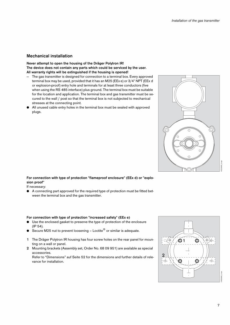
Mechanical installation
Never attempt to open the housing of the Dräger Polytron IR! The device does not contain any parts which could be serviced by the user.All warranty rights will be extinguished if the housing is opened!
— The gas transmitter is designed for connection to a terminal box. Every approved terminal box may be used, provided that it has an M25 (EEx e) or 3/4" NPT (EEx d or explosion-proof) entry hole and terminals for at least three conductors (five when using the RS 485 interface) plus ground. The terminal box must be suitable for the location and application. The terminal box and gas transmitter must be se-cured to the wall / post so that the terminal box is not subjected to mechanical stresses at the connecting point.
●
All unused cable entry holes in the terminal box must be sealed with approved plugs.
For connection with type of protection "flameproof enclosure" (EEx d) or "explo-sion proof"
If necessary:
●
A connecting part approved for the required type of protection must be fitted bet-ween the terminal box and the gas transmitter.
For connection with type of protection "increased safety" (EEx e)
●
Use the enclosed gasket to preserve the type of protection of the enclosure (IP 54).
●
Secure M25 nut to prevent loosening – Loctite
®
or similar is adequate.
1
The Dräger Polytron IR housing has four screw holes on the rear panel for moun-ting on a wall or panel.
2
Mounting brackets (Assembly set, Order No. 68 09 951) are available as special accessories.Refer to “Dimensions” auf Seite 52 for the dimensions and further details of rele-vance for installation.
00
22
35
92
_4.e
ps01
82
35
92
_4.e
ps
1
2

Installation of the gas transmitter
8
Electrical installation
The entire wiring must comply with the applicable local regulations governing the installation of electrical equipment in explosion-hazard areas. If in doubt, the official authority responsible should be consulted before installing the equipment.Devices with measuring function for explosion protection in accordance with Directive 94/9/EC, Annex II, 1.5.5 to 1.5.7, must be operated with a power supply which does not transmit power failures on the primary side lasting for less than 10 ms to the secondary side.
— Installation with 3-wire or multi-wire conductor. Recommendation: Use of a shielded line, shield braiding with a degree of co-verage
≥
80 %. Connection of the shield: to PE on the central controller and not on the transmitter side. In order to ensure correct operation of the gas transmitter, the impedance of the 4 to 20 mA signal loop must not exceed 500 ohm and must lie between 230 and 500 ohm in the case of HART-compatible smart loops. The resistance of the power sup-ply conductors must be sufficiently low to ensure a correct supply voltage at the gas transmitter.
The transmitter must not be supplied with power before the wiring has been completely connected and checked.
●
The terminal box must be electrically connected to ground.
●
Connect the gas transmitter – the connecting leads on the gas transmitter are colour-coded as follows:
●
Connect earthing conductor using an adequate terminal lug fastened to the provided screw, marked .
●
Check the electrical installation to ensure that all conductors have been connected correctly.
●
RS 485 wires are factory-insulated to meet "increased safety" requirements.Do not shorten white and blue wire if RS 485 is not used unless extra terminals are provided. Secure wires mechanically inside terminal box.
If the wiring has been installed in protective tubing:
●
Pour the seals for the protective tubing and allow to cure.
Wiring schematics:
Connection between several gas transmitters and a HART controller with Multidrop capability
●
The gas transmitters must first be started up separately. All gas transmitters to be operated on the Multidrop line must be con-figured with a different polling address between "1" and "15" (see Seite 36 »CONFIGURATION: COMMUNICATION: POL-LING ADDRESS«) via the menu item "Polling address". It is advisable to number the gas transmitters consecutively in ascending order, starting with "1".
red = + (15 to 30 V DC) white = RS 485 communication Ablack = – (common reference potential) blue = RS 485 communication Bbrown = 4 to 20 mA and HART signal output green/yellow = Ground
External Ground Terminal = Ground
+
–
RS
U
blac
k
brow
n
green / yellow
red
RS + Rcabel < 500 Ω
RS = 230 ... 500 Ω;0 ... 500 Ω if the HART-communication is not being used
015
23
59
2_4
_en.
eps
+
–RS
U
blac
k
brow
n
green / yellow
red
RS = 230 ... 500 Ω;0 ... 500 Ω if the HART-communication is not being used
U = Output voltage in V by the powersupply at an output current of 0.4 A
Rcabel (per wire) < Ω U – 15 V 0.8

9
Installation of the gas transmitter
Wiring schematics:
Multidrop installation with HART communication and multiple power supplies.
Multidrop installation with HART communication and one (central) power supply.
●
Up to eight gas transmitters can be connected to one line, depending on the po-wer supply used.
00
32
35
92
_4.e
ps01
22
35
92
_4en
.eps
+
–
1 2 . . . . . . . . . . . . . . 8
RS
+
–UU
+
–U
blac
k
brow
n
green/yellow
red
blac
k
brow
n
green/yellowre
d
blac
k
brow
n
green/yellow
red
RS + Rcable < 500 Ω
RS = 230 ... 500 Ω
013
23
59
2_4
_en.
eps
+
–
1 2 . . . . . . . . . . . . . . 8
RS
U
blac
k
brow
n
green/yellow
red
blac
k
brow
n
green/yellow
red
blac
k
brow
n
green/yellow
red
RS = 230 ... 500 Ω
n = Actual number of gas detectors connected to the power supply
U = Output voltage in V by the power supply at an output current of n x 0.4 A
Rcable (per wire) < Ω U – 15 V n x 0.8

Installation of the gas transmitter
10
Installation of the accessories
Dräger Polytron IR Splash guard
— The Dräger Polytron IR splash guard (Order No. 68 09 750) can be used to pro-tect the optical system in the gas transmitter against water and dust.
●
It must be installed in accordance with the installation instructions (supplied with every splash guard).
— The technical measuring properties of the gas transmitter are not affected by the splash guard. Only the response time may be increased slightly in stationary air.
Dräger Polytron IR Bump Test Adapter
— To test the transmitter Dräger Polytron IR (with splashguard) with a gas-/air-mix-ture of a concentration below the lower explosive limit (span gas), the Dräger Po-lytron IR bump test adapter (Order No. 68 10 985) can be used.
— As wind and convection will more or less cause a dilution, the gas concentration in the transmitter’s optical systems will always be lower than the concentration of the span gas. This is the reason why the bump test adapter is not suitable for ca-libration purposes.
●
It must be installed in accordance with the installation instructions (supplied with every bump test adapter).
— With the use of the bump test adapter neither the approvals nor the measurement performance is affected.
Dräger Polytron IR Flow cell
— The Dräger Polytron IR flow cell (Order No. 68 09 450) is used for function tests with a high test gas concentration. It can be used for gas transmitters with and wi-thout splash guard.
●
It must be installed in accordance with the installation instructions (supplied with every splash guard).
— The technical measuring properties of the gas transmitter are affected by the flow cell!
●
The zero point and sensitivity must always be calibrated after installation or de-installation (Seite 39 and Seite 40).
Dräger Polytron IR Process / gassing adapter
— Only for gas transmitters without splash guard and without flow cell.— The Dräger Polytron IR process / gassing adapter (Order No. 68 09 946) is used
to calibrate a gas transmitter orwhen operating the gas transmitter in pump mode, when the measured gas is sup-plied via an external pump.
●
Plug the process / gassing adapter onto the gas transmitter and secure it with two screws.
— The response time depends on the set volumetric flow rate.— Flow monitoring is required in pump mode.
00
42
35
92
_4.e
ps0
05
23
59
2_4
.eps
00
62
35
92
_4.e
ps

11
Installation of the gas transmitter
Dräger Polytron IR process cuvette
Intended use:— For use of the Dräger Polytron IR gas transmitter in pump operation when the
measured gas is fed to the gas transmitter via external pump.— Gas flow monitoring must be ensured.
How to install the process cuvette:
●
Make sure that none of the seals
(1)
are missing, damaged or incorrectly fitted.
●
Tightly screw together both parts of the process cuvette
(A)
.
●
Mount the tightly screwed process cuvette into the gas transmitter
(B)
and make sure that it fits between pane and mirror of the gas transmitter.
●
Then unscrew the two parts of the process cuvette to a point where the process cuvette fits firmly between pane and mirror of the gas transmitter
(C)
. make sure that the seals
(1)
are correctly positioned. The hose connections can be posi-tioned in any way.
●
Connect gas lines with suitable adapters and seals at the connecting threads. In the process, ensure the compatibility of the material with substance to be monito-red. Gas inlet and gas outlet can be connected in any way.
Calibrate the zero point and the span after installation or deinstallation (Seite 39 and Seite 40).
Technical data:
The Dräger Polytron IR process cuvette may only be used for the following gas transmitters:
— Dräger Polytron IR UL — Order No. 68 09 420— Dräger Polytron IR – type 334 UL — Order No. 68 10 098— Dräger Polytron IR – type 340 UL — Order No. 68 10 820— Dräger Polytron IR CENELEC — Order No. 68 09 800— Dräger Polytron IR – type 334 CENELEC — Order No. 68 10 100— Dräger Polytron IR – type 340 CENELEC — Order No. 68 10 760— Dräger Polytron IR – type 334 IECEx — Order No. 68 11 650— Dräger Polytron IR – type 340 IECEx — Order No. 68 11 640
ATTENTION:A calibration of the zero point and the span is absolutely mandatory every time the process cuvette was installed or deinstalled!
Temperature range:StorageOperational Characteristics – only for IECEx version
–40
o
C to +70
o
C–40
o
C to +65
o
C,–40
o
C to +60
o
C
Pressure range:Ambient pressurePositive pressure between process cuvette and environment
700 to 1300 hPa0 to 100 hPa
Flow rate: 0.5 to 7.0 L/min
Volume flow 0.5 L/min 3.5 L/min 7.0 L/min
Measurement value response time t50
≤6 s ≤4 s ≤4 s
Measurement value response time t90
≤10 s ≤5 s ≤5 s
09
02
35
92
_6.e
ps0
912
35
92
_6.e
ps
1 1
A
09
22
35
92
_6.e
ps
B
09
32
35
92
_6.e
ps
C
Installation of the gas transmitter
12
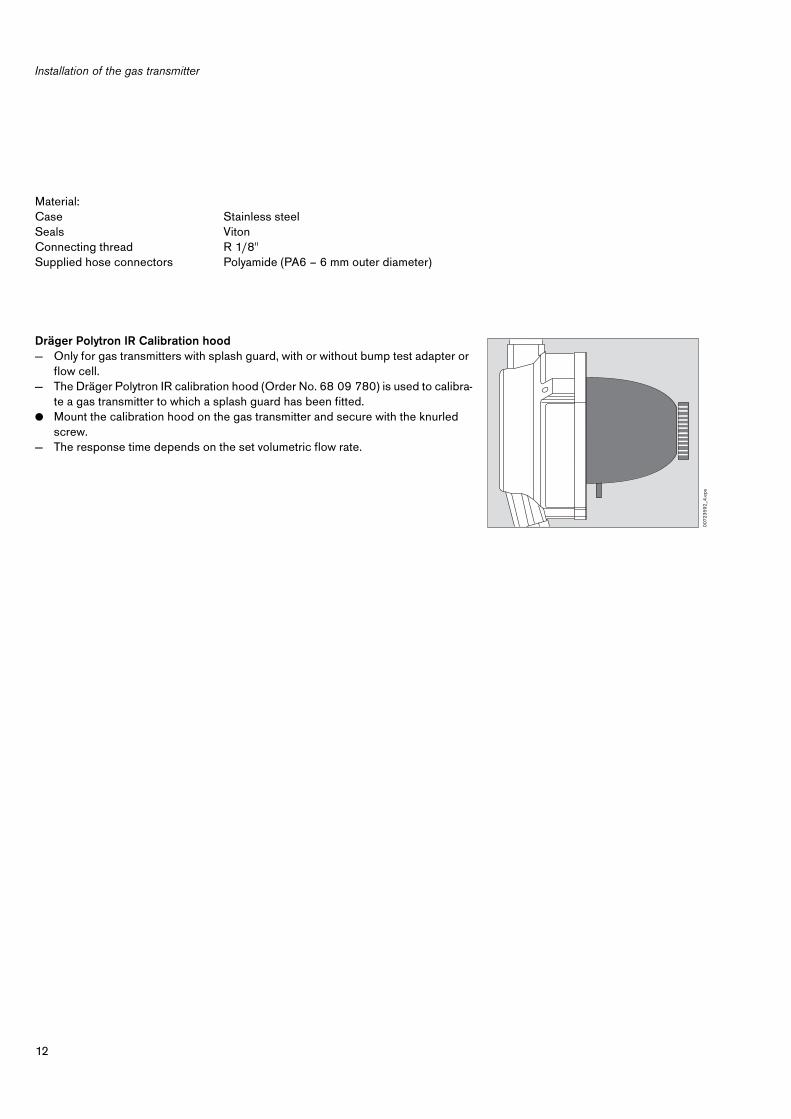
Dräger Polytron IR Calibration hood— Only for gas transmitters with splash guard, with or without bump test adapter or
flow cell.— The Dräger Polytron IR calibration hood (Order No. 68 09 780) is used to calibra-
te a gas transmitter to which a splash guard has been fitted.● Mount the calibration hood on the gas transmitter and secure with the knurled
screw.— The response time depends on the set volumetric flow rate.
Material:CaseSealsConnecting threadSupplied hose connectors
Stainless steelVitonR 1/8"Polyamide (PA6 – 6 mm outer diameter)
007
23
59
2_4
.eps

13
Operation
Operation
System start-up
The Dräger Polytron IR gas transmitter is set to methane (type 334) or propane (type 340) on delivery and is immediately ready for use after installation.
● Deactivate the alarm trigger of the control system in order to avoid false alarms.● Switch on the power supply to the transmitter. The gas transmitter runs through a
self-test and then automatically operates with the calibration and mode set on de-livery.
● Check whether the calibration and configuration set on delivery are appropriate for the intended use of the transmitter – see "Configuring the gas transmitter", Seite 14.
● Check signal transmission to the controller and alarm triggering, see Seite 42 to Seite 44. National regulations may make it necessary to calibrate the zero point and sensitivity. Calibration procedure: see Seite 39 and Seite 40.
● Reactivate the alarm trigger to restore the system to its normal operating conditi-on.
— Parts of the transmitter housing are heated internally to prevent condensation of water on the mirror or window. For this reason, the surface temperature may increase by 10 to 20 oC.
Operation
14
Configuring the gas transmitter
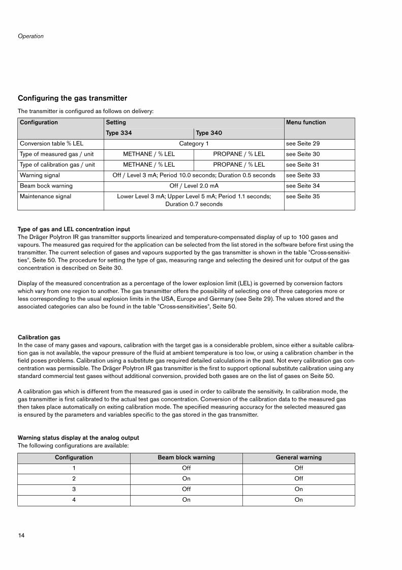
The transmitter is configured as follows on delivery:
Type of gas and LEL concentration inputThe Dräger Polytron IR gas transmitter supports linearized and temperature-compensated display of up to 100 gases and vapours. The measured gas required for the application can be selected from the list stored in the software before first using the transmitter. The current selection of gases and vapours supported by the gas transmitter is shown in the table "Cross-sensitivi-ties", Seite 50. The procedure for setting the type of gas, measuring range and selecting the desired unit for output of the gas concentration is described on Seite 30.
Display of the measured concentration as a percentage of the lower explosion limit (LEL) is governed by conversion factors which vary from one region to another. The gas transmitter offers the possibility of selecting one of three categories more or less corresponding to the usual explosion limits in the USA, Europe and Germany (see Seite 29). The values stored and the associated categories can also be found in the table "Cross-sensitivities", Seite 50.
Calibration gasIn the case of many gases and vapours, calibration with the target gas is a considerable problem, since either a suitable calibra-tion gas is not available, the vapour pressure of the fluid at ambient temperature is too low, or using a calibration chamber in the field poses problems. Calibration using a substitute gas required detailed calculations in the past. Not every calibration gas con-centration was permissible. The Dräger Polytron IR gas transmitter is the first to support optional substitute calibration using any standard commercial test gases without additional conversion, provided both gases are on the list of gases on Seite 50.
A calibration gas which is different from the measured gas is used in order to calibrate the sensitivity. In calibration mode, the gas transmitter is first calibrated to the actual test gas concentration. Conversion of the calibration data to the measured gas then takes place automatically on exiting calibration mode. The specified measuring accuracy for the selected measured gas is ensured by the parameters and variables specific to the gas stored in the gas transmitter.
Warning status display at the analog outputThe following configurations are available:
Configuration Setting Menu function
Type 334 Type 340
Conversion table % LEL Category 1 see Seite 29
Type of measured gas / unit METHANE / % LEL PROPANE / % LEL see Seite 30
Type of calibration gas / unit METHANE / % LEL PROPANE / % LEL see Seite 31
Warning signal Off / Level 3 mA; Period 10.0 seconds; Duration 0.5 seconds see Seite 33
Beam bock warning Off / Level 2.0 mA see Seite 34
Maintenance signal Lower Level 3 mA; Upper Level 5 mA; Period 1.1 seconds; Duration 0.7 seconds
see Seite 35
Configuration Beam block warning General warning
1 Off Off
2 On Off
3 Off On
4 On On

15
Operation
Beam block warning (Patented by Dräger Safety)Although the Dräger Polytron IR gas transmitter has effective devices to protect the optical system, gradual fouling of the beam path under severe conditions of use cannot be ruled out altogether. To prevent interference with measurement due to heavy con-tamination, the Dräger Polytron IR gas transmitter has been equipped with a system which gives advance warning of fouling of the beam path before any interference occurs, without causing a complete breakdown in measurement. The beam block warning can be activated for this purpose (configuration 2 in the table).If a build-up of dirt causes the light intensity at the inlet to the optical measuring unit to fall below a critical value, such that suf-ficient stability of the measuring signal is no longer guaranteed, the gas transmitter emits a constant current of 2 mA at the ana-log interface when the beam block warning is activated. Since the residual light intensity is still high enough to guarantee reliable detection of alarm states above 15 % LEL, measurement of the current gas concentration continues in the background. Any hazard arising due to explosive gases above a concentration of 15 % LEL is still detected. The transmitter switches itself back to measuring mode and reliably displays the hazard at the analog output or digital.This system allows scheduled servicing to be planned and controlled more efficiently, as immediate access / cleaning is not necessary. If the contamination reaches such a degree that reliable detection of gas concentrations above 15 % LEL is no longer possible, a fault status is reported with the associated 1 mA analog signal or digital. In this case, the system is no longer ready for measurement.
Other analog displays when a warning occursA second way of displaying a warning status at the analog output is the option of activating the warning function described on Seite 32 (configuration 3 in the table). In this case, a warning is displayed with output of a 3 mA level for 0.7 second. This is repeated every 10 seconds. Besides the general warnings, this function also indicates increased contamination which may cause the signal to become unstable. Heavier fouling is indicated by emitting an error status at 1 mA as described above.
A combination of the two analog warnings described above is also possible (configuration 4 in the table). Whereas general warnings are then indicated by the level of 3 mA for 0.7 seconds, in this case a beam block warning is treated separately and indicated in analog form by a 2 mA signal.
Operation
16
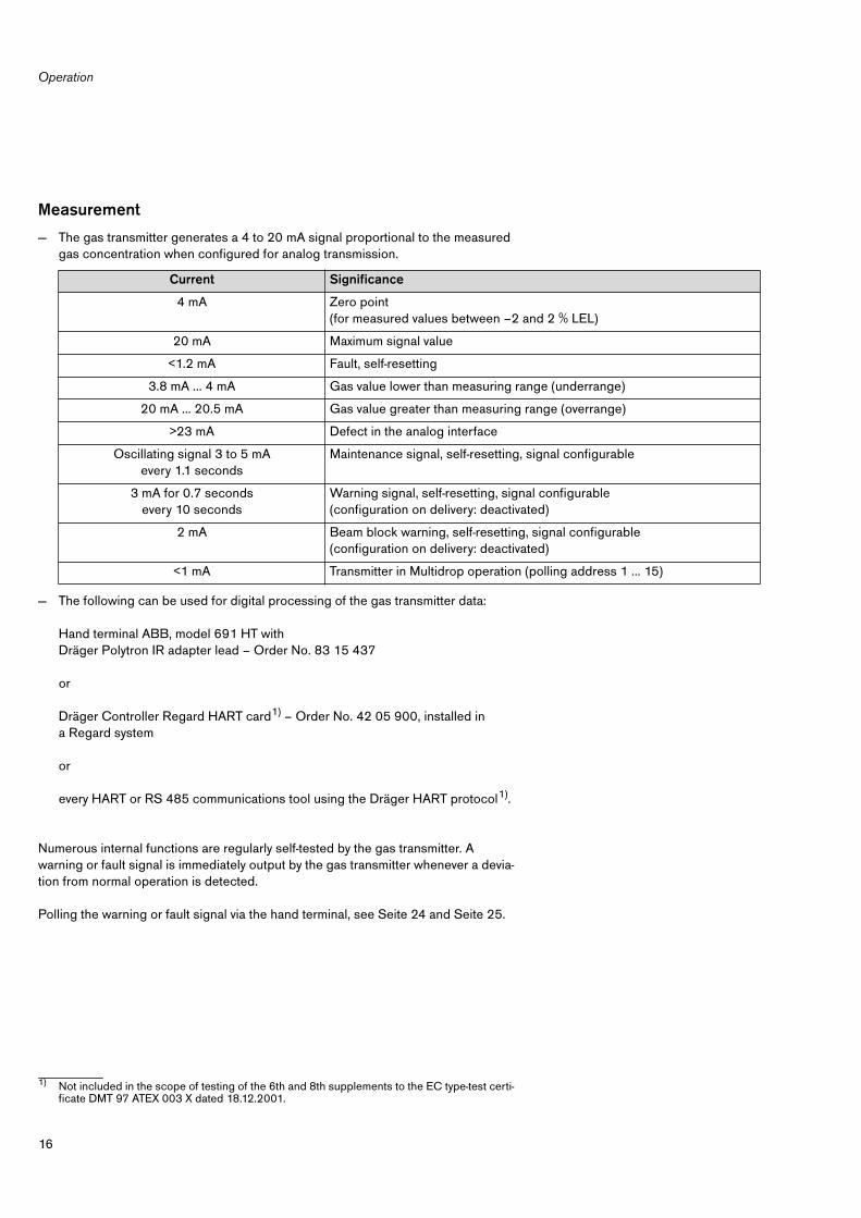
Measurement
— The gas transmitter generates a 4 to 20 mA signal proportional to the measured gas concentration when configured for analog transmission.
— The following can be used for digital processing of the gas transmitter data:
Hand terminal ABB, model 691 HT with Dräger Polytron IR adapter lead – Order No. 83 15 437
or
Dräger Controller Regard HART card1) – Order No. 42 05 900, installed in a Regard system
or
every HART or RS 485 communications tool using the Dräger HART protocol1).
Numerous internal functions are regularly self-tested by the gas transmitter. A warning or fault signal is immediately output by the gas transmitter whenever a devia-tion from normal operation is detected.
Polling the warning or fault signal via the hand terminal, see Seite 24 and Seite 25.
Current Significance
4 mA Zero point (for measured values between –2 and 2 % LEL)
20 mA Maximum signal value
<1.2 mA Fault, self-resetting
3.8 mA ... 4 mA Gas value lower than measuring range (underrange)
20 mA ... 20.5 mA Gas value greater than measuring range (overrange)
>23 mA Defect in the analog interface
Oscillating signal 3 to 5 mA every 1.1 seconds
Maintenance signal, self-resetting, signal configurable
3 mA for 0.7 secondsevery 10 seconds
Warning signal, self-resetting, signal configurable (configuration on delivery: deactivated)
2 mA Beam block warning, self-resetting, signal configurable (configuration on delivery: deactivated)
<1 mA Transmitter in Multidrop operation (polling address 1 … 15)
1) Not included in the scope of testing of the 6th and 8th supplements to the EC type-test certi-ficate DMT 97 ATEX 003 X dated 18.12.2001.

17
Maintenance
Maintenance
Maintenance intervals
● EN 50073 and the relevant national regulations must be observed.
Daily● Visual inspection to establish readiness for use.
When starting● Check calibration of the zero point, Seite 39.● Check current interface, Seite 42.● Check that display on transmitter (hand terminal) matches that on controller.
If it does not:Calibrate current interface, Seite 45.
At regular intervalsto be determined by the person responsible for the gas warning system – recommended interval: every six months:● Check calibration of the zero point and sensitivity, Seite 39 to Seite 40.● Check signal transmission to the controller and alarm triggering, Seite 42.
● The calibration interval can be extended beyond the recommended six months under the following conditions: After a maxi-mum period of use of six months, check that the gas can still reach the cuvette without obstruction due to dust or oil, for ex-ample. The calibration interval may be extended – recommendation: not more than 24 months – if limited functionality due to these effects can be excluded.
Annually● Inspection by experts.
The intervals between inspections must be defined separately in each case, depending on the safety requirements, technical process conditions and technical requirements of the equipment.We recommend that a service contract be obtained with, and all repairs carried out by, DrägerService.
Maintenance
18
Checking and if necessary cleaning the cuvette in the gas transmitter
● OPTIONAL:To avoid false alarms during inspection, set the analog output signal to mainte-nance signal, see Seite 35.
● Remove the splash guard from the gas transmitter.● Examine air inlets and outlets for signs of damage and contamination.● Examine the mirror and window for signs of contamination, clean with water
or alcohol and wipe dry with cotton wool or a cloth.Do not scratch the mirror or window!
● Refit the splash guard to the gas transmitter.● Reactivate the analog output signal if set to maintenance signal.
19
Fault, cause, remedy
Fault, cause, remedy
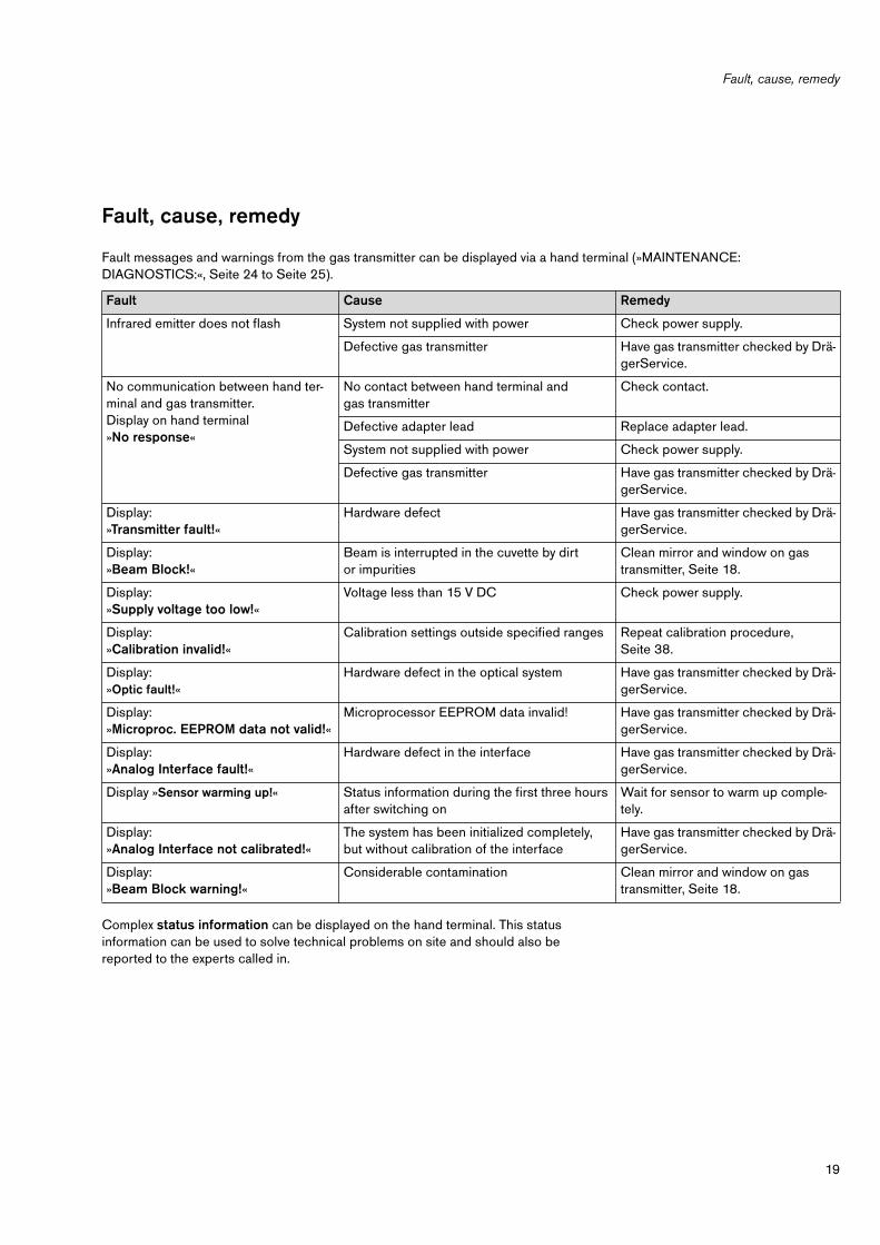
Fault messages and warnings from the gas transmitter can be displayed via a hand terminal (»MAINTENANCE: DIAGNOSTICS:«, Seite 24 to Seite 25).
Fault Cause Remedy
Infrared emitter does not flash System not supplied with power Check power supply.
Defective gas transmitter Have gas transmitter checked by Drä-gerService.
No communication between hand ter-minal and gas transmitter. Display on hand terminal»No response«
No contact between hand terminal and gas transmitter
Check contact.
Defective adapter lead Replace adapter lead.
System not supplied with power Check power supply.
Defective gas transmitter Have gas transmitter checked by Drä-gerService.
Display: »Transmitter fault!«
Hardware defect Have gas transmitter checked by Drä-gerService.
Display: »Beam Block!«
Beam is interrupted in the cuvette by dirt or impurities
Clean mirror and window on gas transmitter, Seite 18.
Display: »Supply voltage too low!«
Voltage less than 15 V DC Check power supply.
Display: »Calibration invalid!«
Calibration settings outside specified ranges Repeat calibration procedure, Seite 38.
Display: »Optic fault!«
Hardware defect in the optical system Have gas transmitter checked by Drä-gerService.
Display: »Microproc. EEPROM data not valid!«
Microprocessor EEPROM data invalid! Have gas transmitter checked by Drä-gerService.
Display: »Analog Interface fault!«
Hardware defect in the interface Have gas transmitter checked by Drä-gerService.
Display »Sensor warming up!« Status information during the first three hours after switching on
Wait for sensor to warm up comple-tely.
Display: »Analog Interface not calibrated!«
The system has been initialized completely, but without calibration of the interface
Have gas transmitter checked by Drä-gerService.
Display: »Beam Block warning!«
Considerable contamination Clean mirror and window on gas transmitter, Seite 18.
Complex status information can be displayed on the hand terminal. This status information can be used to solve technical problems on site and should also be reported to the experts called in.
Method of operation
20
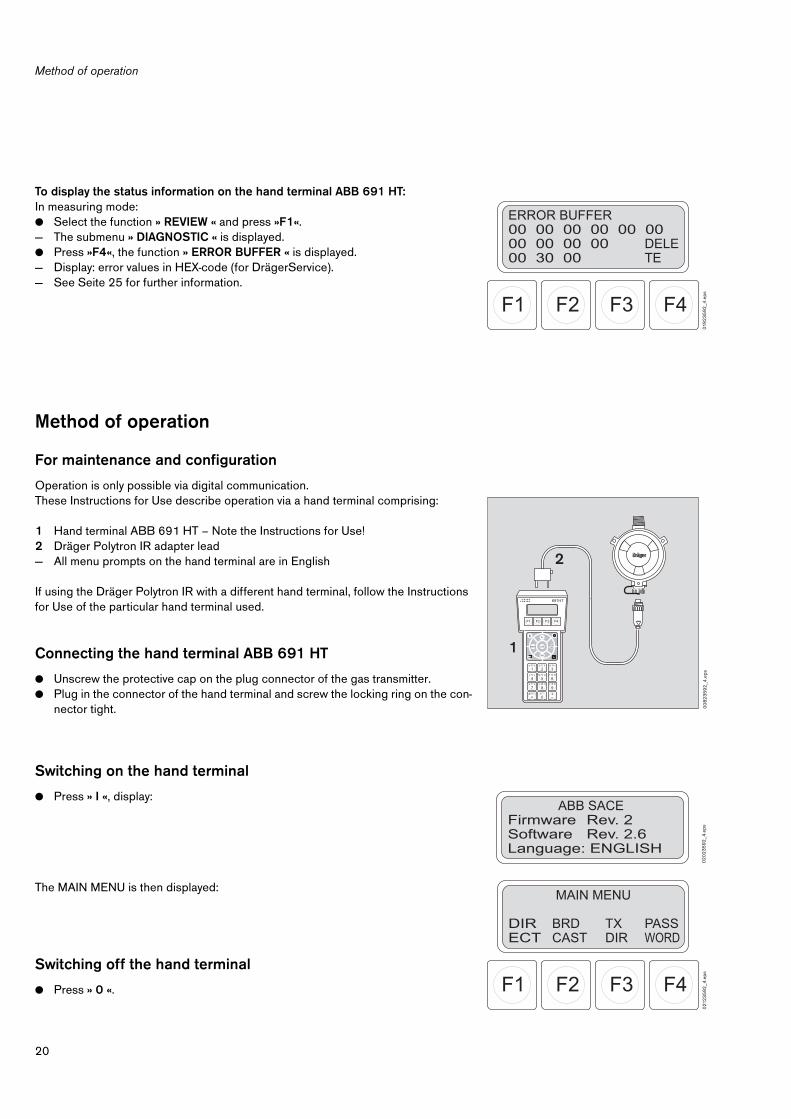
To display the status information on the hand terminal ABB 691 HT:In measuring mode:● Select the function » REVIEW « and press »F1«.— The submenu » DIAGNOSTIC « is displayed.● Press »F4«, the function » ERROR BUFFER « is displayed.— Display: error values in HEX-code (for DrägerService).— See Seite 25 for further information.
Method of operation
For maintenance and configuration
Operation is only possible via digital communication.These Instructions for Use describe operation via a hand terminal comprising:
1 Hand terminal ABB 691 HT – Note the Instructions for Use!2 Dräger Polytron IR adapter lead— All menu prompts on the hand terminal are in English
If using the Dräger Polytron IR with a different hand terminal, follow the Instructions for Use of the particular hand terminal used.
Connecting the hand terminal ABB 691 HT
● Unscrew the protective cap on the plug connector of the gas transmitter.● Plug in the connector of the hand terminal and screw the locking ring on the con-
nector tight.
Switching on the hand terminal
● Press » I «, display:
The MAIN MENU is then displayed:
Switching off the hand terminal
● Press » 0 «.
F4F3F2F1
ERROR BUFFER00 00 00 00 00 0000 00 00 0000 30 00
DELETE
019
23
59
2_4
.eps
00
82
35
92
_4.e
ps
691HT
F4F3F2F1
1A B C
2D E F
3G H I
4J K L
5M N O
6P Q R
7S T U
8V W X
9Y Z #
•@ % c
0& / +
–
I PV
REWIEW CONF SERIALLINK
TRIM
1
2
ABB SACEFirmware Rev. 2Software Rev. 2.6Language: ENGLISH
02
02
35
92
_4.e
ps
F4F3F2F1
MAIN MENU
DIRECT
BRDCAST
TXDIR
PASSWORD
021
23
59
2_4
.eps
21
Method of operation
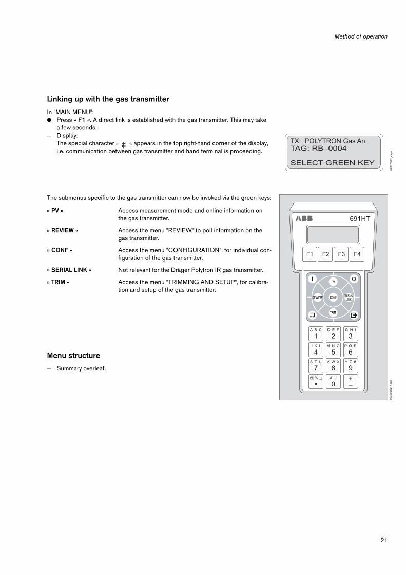
Linking up with the gas transmitter
In "MAIN MENU":● Press » F1 «. A direct link is established with the gas transmitter. This may take
a few seconds.— Display:
The special character » « appears in the top right-hand corner of the display, i.e. communication between gas transmitter and hand terminal is proceeding.
The submenus specific to the gas transmitter can now be invoked via the green keys:
Menu structure
— Summary overleaf.
» PV « Access measurement mode and online information on the gas transmitter.
» REVIEW « Access the menu "REVIEW" to poll information on the gas transmitter.
» CONF « Access the menu "CONFIGURATION", for individual con-figuration of the gas transmitter.
» SERIAL LINK « Not relevant for the Dräger Polytron IR gas transmitter.
» TRIM « Access the menu "TRIMMING AND SETUP", for calibra-tion and setup of the gas transmitter.
TX: POLYTRON Gas An.TAG: RB–0004
SELECT GREEN KEY
02
22
35
92
_4.e
ps
691HT
F4F3F2F1
1A B C
2D E F
3G H I
4J K L
5M N O
6P Q R
7S T U
8V W X
9Y Z #
•@ % c
0& / +
–
I PV
REWIEW CONF SERIALLINK
TRIM
02
32
35
92
_4.e
ps

Method of operation
22
PV (Dynamic Var)
1 2
3 REVIEW
1 2
4 CONFIGURATION
1 2
7 TRIM
1 3
8
MEASUREMENT
1 2
3 DIAGNOSTICS
1 2
4 INITIALISATION
1 2
8 CALIBRATE SENSOR
1 3
8
ON LINE INFO
1 2
3 Faults
1 2
4 Factory setting
1 2
8 Zero
1 3
9
Warnings1
25 Span
1 4
0
SET CATEGORY
1 2
9
Sensor Temperature
1 2
5
SET ANALOG
1 4
2
Error Buffer
1 2
5 GAS + RANGE
1 3
0
1 – 22 mA
1 4
2
Gas Name
1 3
0
TRANSMITTER INFO
1 2
6 4 mA
1 4
3
Units
1 3
0Hardware part no.
1 2
6 20 mA
1 4
3
Range1
30
Hardware serial no.
1 2
6 Value
1 4
3
Software part no.
1 2
6
CALIBRATION PARAM
1 3
1
Testing
1 4
3
Software version
1 2
6 Gas Cal.
1 3
1 Warning
1 4
4
Units
1 3
1 Fault
1 4
4SPECIAL SIGNALS
1 3
2 Beam Block1
44
Warning on/off
1 3
2 Maintenance
1 4
4
Warning level
1 3
3 CALIBRATE ANALOG
1 4
5
Beam Block
1 3
4 4 mA
1 4
5
Maintenance level
1 3
5 20 mA
1 4
6
COMMUNICATION
1 3
6
Polling address
1 3
6
Unique identifier
1 3
7
Tag
1 3
7

23
"PV" menu (Dynamic Var)
"PV" menu (Dynamic Var)
The "PV" menu (green "PV" key in the function cross on the hand terminal) contains the functions "MEASUREMENT TYPE" and "ON LINE INFO".
MEASUREMENT TYPE
This function displays the measured value.
● Press the green » PV « key on the hand terminal.— The current measured value is displayed.
To exit the function:● Press » « on the hand terminal.
ON LINE INFO
This function displays information and error values for the current operating mode in HEX-code (for DrägerService).
● Press the green » PV « key on the hand terminal.● Press » F1 «.— The function "ON LINE INFO" is displayed:
To exit the function:● Press » « on the hand terminal.
F4F3F2F1
MEASUREMENT TYPE:0.0ONLIINFO
%LEL METHANE METHANE
024
23
59
2_4
.eps
F4F3F2F1
ON LINE INFO00 00 00 00 00 0000 00 00 00 00 10 00
02
52
35
92
_4.e
ps

"REVIEW" menu
24
"REVIEW" menu
The "REVIEW" menu (green » REVIEW « key in the function cross on the hand termi-nal) contains a number of functions with which gas transmitter data can be polled.The "REVIEW" menu is made up of a number of submenus and functions. The sub-menus are similarly made up of a number of functions – summary, see Seite 22.
● Press the green » REVIEW « key on the hand terminal. — The menu is displayed:
Selection of submenus:» DIAGNOSTICS: «» TRANSMITTER INFO: «
To select a submenu:— Press » F1 « or » F2 «.
DIAGNOSTIC
The submenu "DIAGNOSTIC" includes all functions for polling the status and a num-ber of variables of importance for preventive maintenance and for investigating the suspected causes of faults.
Selection of functions:» DIAGNOSTICS: «— Faults — Warnings — Sensor Temperature — Error buffer.
Then select the function:● Press » F1 «, » F2 «, » F3 « or » F4 «.
Return to previous menu:● Press » « on the hand terminal.
FAULTS
This function is used to display the device faults which have occurred. Faults are des-cribed in plain English.An existing fault is identified by the symbol » F « in the top right-hand corner of the display.
To invoke the function:● Press » F1 « on the hand terminal – display, e.g.:— Use the keys » F1 « and » F2 « to scroll through the fault list.— See “Fault, cause, remedy” auf Seite 19 for information on how to remedy a fault.
F4F3F2F1
REVIEW
DIAGNOST.
TXINFO
02
62
35
92
_4.e
ps
F4F3F2F1
DIAGNOSTIC
FAULTS
WARNINGS
SENSTEMP
ERRBUFF
027
23
59
2_4
.eps
FAULTS:NO ERRORS
02
92
35
92
_4.e
ps

25
"REVIEW" menu
WARNINGS
This function is used to display the warnings which have been generated.The warnings allow the operator to introduce preventive maintenance measures in order to counteract a device fault before it occurs.
To invoke the function:● Press » F2 « on the hand terminal – display, e.g.:— Use the keys » F1 « and » F2 « to scroll through the fault list.— See “Fault, cause, remedy” auf Seite 19 for information on how to remedy a fault.
SENSOR TEMPERATURE
This function is used to display the current sensor temperature.
To invoke the function:● Press » F3 « on the hand terminal – display, e.g.:
Return to previous menu:Press » « on the hand terminal.
ERROR BUFFER (error values in HEX code)
The function is used to display error values in HEX code (for DrägerService).
To invoke the function:● Press » F4 « on the hand terminal – display, e.g.:— The first row shows system faults 1 to 5.— The second row shows transmitter faults 1 to 5.— The third row shows the system warning, transmitter warning 1 and
transmitter warning 2.
To delete the error buffer:while the function is active, press » F4 «.
Return to previous menu:● Press » « on the hand terminal.
WARNINGS:Sensor Warming up
03
02
35
92
_4.e
ps
SENSOR TEMPERATURE41.21 Deg.C
031
23
59
2_4
.eps
F4F3F2F1
ERROR BUFFER00 00 00 00 00 0000 00 00 0000 30 00
DELETE
019
23
59
2_4
.eps

"REVIEW" menu
26
TRANSMITTER INFO
The submenu "TRANSMITTER INFO" contains functions concerning information on the gas transmitter.
Selection of functions:» TRANSMITTER INFO: « (information on the gas transmitter)— Hardware part no.— Hardware serial no.— Software part no.— Software version.
Then select the function:● Press » F1 «, » F2 «, » F3 « or » F4 «.
Return to previous menu:● Press » « on the hand terminal.
HW Part Number
The part number of the electronics in the gas transmitter is displayed.
To invoke the function:● Press » F1 « on the hand terminal – display, e.g.:
HW Serial Number
The serial number of the electronics in the gas transmitter is displayed.
To invoke the function:● Press » F2 « on the hand terminal – display, e.g.:
SW Part Number
The part number of the software is displayed.
To invoke the function:● Press » F3 « on the hand terminal – display, e.g.:
SW Version
The version number of the software is displayed.
To invoke the function:● Press » F4 « on the hand terminal – display, e.g.:
Return to previous menu:● Press » « on the hand terminal.
F4F3F2F1
TRANSMITTER INFO
HWPART
HWSERN
SWPART
SWVERS
027
23
59
2_4
.eps
HW Part Number6809710
03
22
35
92
_4.e
ps
HW Serial NumberARRA0493
03
32
35
92
_4.e
ps
SW Part Number8314666
03
42
35
92
_4.e
ps
SW Version:010
03
52
35
92
_4.e
ps

27
"CONFIGURATION" menu
"CONFIGURATION" menu
The "CONFIGURATION" menu (green » CONF « key in the function cross on the hand terminal) contains a number of functions with which the gas transmitter can be configured in accordance with individual requirements.The "CONFIGURATION" menu is made up of a number of submenus and functions. The submenus are similarly made up of a number of functions – summary, see Seite 22.
● Press the green » CONF « key on the hand terminal. — The menu is displayed:
Selection of submenus:» INITIALISATION: « » SET CATEGORY: « (category of the LEL conversion factor)» GAS + RANGE: « (gas type and measurement range)» CALIBRATION PARAM: « » SPECIAL SIGNALS: « » COMMUNICATION: «
To select a submenu:— Press » F1 «, » F2 « or » F3 « to select one of the first three submenus.— Press » F4 « to display the next three submenus, then press » F1 «, » F2 « or » F3 «
to select one of the last three submenus.
F4F3F2F1
CONFIGURATION:
INITIAL.
SETCATG
GAS+RANGE
NEXT
03
62
35
92
_4.e
ps
F4F3F2F1
CONFIGURATION:
CAL.PARM
SPECSIGN.
COMMUNIC.
PREVIOUS
037
23
59
2_4
.eps
"CONFIGURATION" menu
28
INITIALIZATION
This function resets a number of gas transmitter parameters to the default values set by the manufacturer. The maintenance signal is output at the analog interface during this function.A maintenance signal is not output via the current interface when the gas transmitter is in HART mode; the gas transmitter is not reset to 4 to 20 mA mode by the function "Initialize factory settings".
The following configuration parameters are reset to the specified factory settings:
The gas transmitter must be recalibrated after initialization!
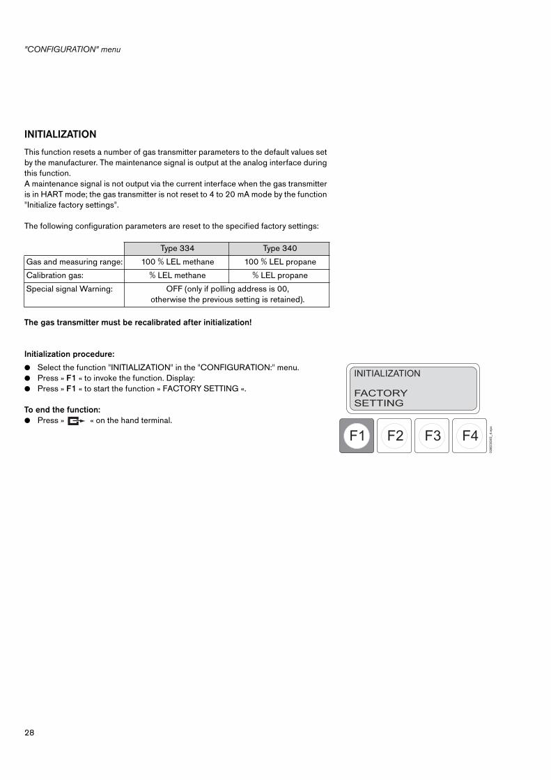
Initialization procedure:
● Select the function "INITIALIZATION" in the "CONFIGURATION:" menu.● Press » F1 « to invoke the function. Display:● Press » F1 « to start the function » FACTORY SETTING «.
To end the function:● Press » « on the hand terminal.
Type 334 Type 340
Gas and measuring range: 100 % LEL methane 100 % LEL propane
Calibration gas: % LEL methane % LEL propane
Special signal Warning: OFF (only if polling address is 00, otherwise the previous setting is retained).
F4F3F2F1
INITIALIZATION
FACTORYSETTING
03
82
35
92
_4.e
ps

29
"CONFIGURATION" menu
SET CATEGORY
(Setting the category of the conversion factor % LEL according to % v/v)
This function can be used to select one of three categories of conversion factor.
The values for the categories stored in the software can be found in the "Cross-sen-sitivities" table on Seite 50.
Select the function:● Select the function "SET CATEGORY" in the "CONFIGURATION:" menu.● Press » F2 « to invoke the function. Display:— The active category is displayed in the top right-hand corner (value in square brak-
kets).
Select category:● Press » F1 « (category 1), » F2 « (category 2) or » F3 « (category 3).
To end the function:● Press » « on the hand terminal.
— Category 1: based on NIOSH
— Category 2: based on IEC 60079-20
— Category 3: based on Nabert/Schoen (safety indices for flammable gases and vapours)
F4F3F2F1
SET CATEGORY [ 1 ]
CAT1
CAT2
CAT3
03
92
35
92
_4.e
ps
"CONFIGURATION" menu
30
GAS + RANGE
(Configuring the type of gas, units and measuring range)
The type of gas to be measured, the unit of measurement and the measuring range can be configured with the aid of this function. The maintenance signal is output at the analog interface during this function.
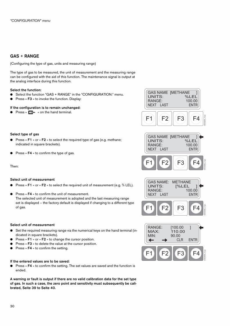
Select the function:● Select the function "GAS + RANGE" in the "CONFIGURATION:" menu.● Press » F3 « to invoke the function. Display:
If the configuration is to remain unchanged:● Press » « on the hand terminal.
Select type of gas
● Press » F1 « or » F2 « to select the required type of gas (e.g. methane; indicated in square brackets).
● Press » F4 « to confirm the type of gas.
Then:
Select unit of measurement
● Press » F1 « or » F2 « to select the required unit of measurement (e.g. % LEL).
● Press » F4 « to confirm the unit of measurement.The selected unit of measurement is adopted and the last measuring range set is displayed – the factory default is displayed if changing to a different type of gas.
Select unit of measurement
● Set the required measuring range via the numerical keys on the hand terminal (in-dicated in square brackets).
● Press » F1 « or » F2 « to change the cursor position.● Press » F3 « to delete the value at the cursor position.● Press » F4 « to confirm the setting.
If the entered values are to be saved:● Press » F4 « to confirm the setting. The set values are saved and the function is
ended.
A warning or fault is output if there are no valid calibration data for the set type of gas. In such a case, the zero point and sensitivity must subsequently be cali-brated, Seite 39 to Seite 40.
F4F3F2F1
GAS NAME [METHANE ]UNITS: %LELRANGE: 100.00NEXT LAST ENTR
04
02
35
92
_4.e
ps
F4F3F2F1
GAS NAME [METHANE ]UNITS: %LELRANGE: 100.00NEXT LAST ENTR
041
23
59
2_4
.eps
F4F3F2F1
GAS NAME: METHANEUNITS: [%LEL ]RANGE: 100.00NEXT LAST ENTR
04
22
35
92
_4.e
ps
F4F3F2F1
RANGE: [100.00 ]MAX: 110.00MIN: 90.00 CLR ENTR
04
32
35
92
_4.e
ps

31
"CONFIGURATION" menu
CALIBRATION PARAM.
(Configuring the calibration parameters)Calibration parameters which have only to be set once can be configured with the aid of this submenu. The maintenance signal is output at the analog interface during this function.
Select the function:● Select the function "CALIBRATION PARAM." in the "CONFIGURATION:" menu.● Press » F1 « to invoke the function. Display:
If the configuration is to remain unchanged:● Press » « on the hand terminal.
Select type of calibration gas
● Press » F1 « or » F2 « to select the required type of gas (e.g. methane; indicated in square brackets).
● Press » F4 « to confirm the type of gas.
Then:
Select calibration gas unit
● Press » F1 « or » F2 « to select the required unit of measurement (e.g. % LEL).
● Press » F4 « to confirm the units.The selected unit of measurement is adopted and the function is ended. The concentration is once again output at the 4 to 20 mA interface.
F4F3F2F1
GAS CAL: [METHANE ]UNITS: %LELNEXTOPTN
LASTOPTN
ENTR
04
42
35
92
_4.e
ps
F4F3F2F1
GAS CAL: [METHANE ]UNITS: %LELNEXTOPTN
LASTOPTN
ENTR
04
52
35
92
_4.e
ps
F4F3F2F1
GAS CAL: METHANEUNITS: [%LEL ]NEXTOPTN
LASTOPTN
ENTR
04
52
35
92
_4.e
ps
"CONFIGURATION" menu
32
SPECIAL SIGNAL
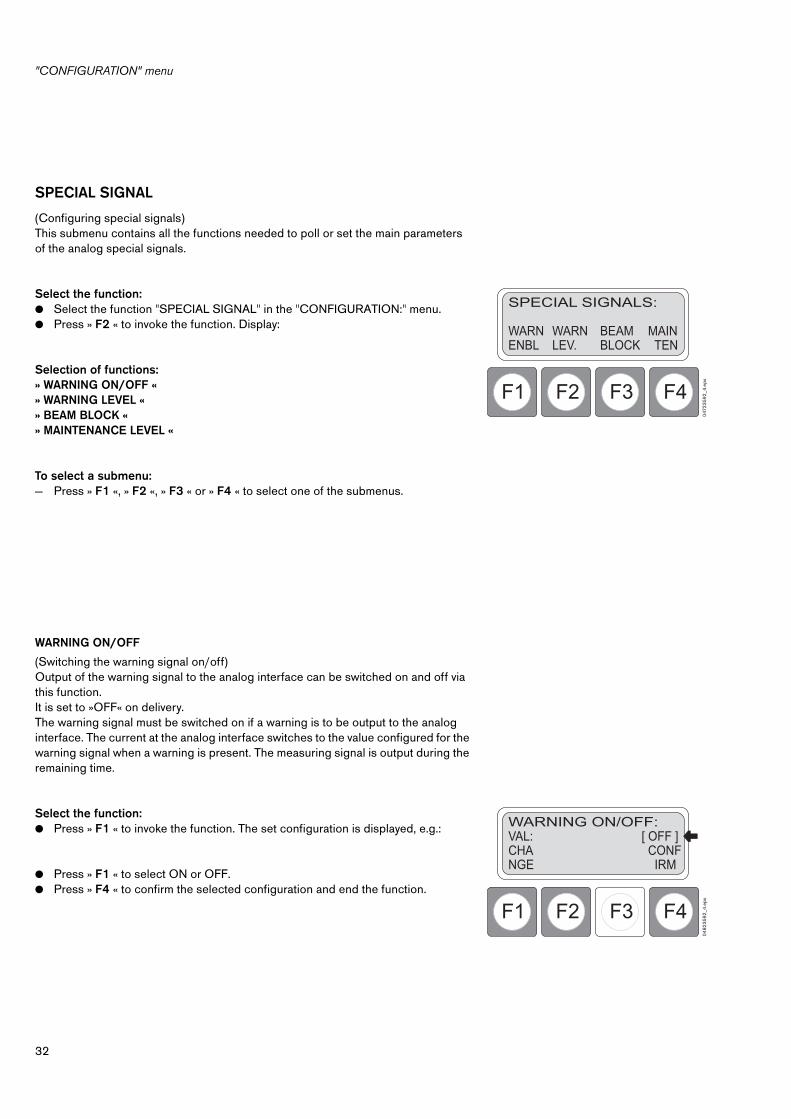
(Configuring special signals)This submenu contains all the functions needed to poll or set the main parameters of the analog special signals.
Select the function:● Select the function "SPECIAL SIGNAL" in the "CONFIGURATION:" menu.● Press » F2 « to invoke the function. Display:
Selection of functions:» WARNING ON/OFF « » WARNING LEVEL « » BEAM BLOCK « » MAINTENANCE LEVEL «
To select a submenu:— Press » F1 «, » F2 «, » F3 « or » F4 « to select one of the submenus.
WARNING ON/OFF
(Switching the warning signal on/off)Output of the warning signal to the analog interface can be switched on and off via this function.It is set to »OFF« on delivery.The warning signal must be switched on if a warning is to be output to the analog interface. The current at the analog interface switches to the value configured for the warning signal when a warning is present. The measuring signal is output during the remaining time.
Select the function:● Press » F1 « to invoke the function. The set configuration is displayed, e.g.:
● Press » F1 « to select ON or OFF.● Press » F4 « to confirm the selected configuration and end the function.
F4F3F2F1
SPECIAL SIGNALS:
WARNENBL
WARNLEV.
BEAMBLOCK
MAIN TEN
047
23
59
2_4
.eps
F4F3F2F1
WARNING ON/OFF:VAL: [ OFF ]CHANGE
CONF IRM
04
82
35
92
_4.e
ps

33
"CONFIGURATION" menu
WARNING LEVEL
(Setting the warning signal)This function can be used to set the form in which the warning signal is output at the analog interface.
Select the function:● Press » F2 « to invoke the function. The set momentary configuration is
displayed, e.g.:
If the setting is to remain unchanged:● Press » « on the hand terminal.
● Set the threshold value via the numerical keys on the hand terminal (value in square brackets). Setting range: 0.7 to 22 mA.
● Press » F1 « or » F2 « to change the cursor position.● Press » F3 « to delete the value at the cursor position.● Press » F4 « to confirm the setting.
— The display changes for setting the period between signals (» Period «).This value is also entered via the numerical keys on the hand terminal and confir-med by pressing » F4 «. The range of values that can be set equals 0.1 to 600 se-conds – recommended value: e.g. 10 seconds.
— The display changes for setting the duration of a signal (» Duration «).This value is also entered via the numerical keys on the hand terminal and confirmed by pressing » F4 «. The function is ended.The range of values that can be set equals 0.1 to 600 seconds – recommended value: e.g. 0.7 seconds. Rule: the duration is less than or equal to the period.
F4F3F2F1
WARNING LEVEL:LEVEL: [ 3.00 ] mA1.0 <= Cur <= 22.0
ENTR CLR
04
92
35
92
_6.e
ps
F4F3F2F1
WARNING LEVEL:PERIOD: [ 10.0 ] secDURATION: 0.7 sec
ENTR CLR
05
02
35
92
_6.e
psF4F3F2F1
WARNING LEVEL:PERIOD: 10.0 secDURATION: [ 0.7 ] sec
ENTR CLR
051
23
59
2_6
.eps

"CONFIGURATION" menu
34
BEAM BLOCK
(Configuring the beam block warning)This function is used to activate or deactivate the beam block warning output at the analog interface.The setting on delivery is »OFF«.The warning must be activated in order to transmit the presence of a beam block warning via the analog interface. In the event of a warning, a constant current of 2 mA is switched to the analog interface. See Seite 14 for details.
Select the function:● Press » F3 « to invoke the function. The set momentary configuration is
displayed, e.g.:
● Press » F1 « to select ON or OFF.● Press » F4 « to confirm the selected configuration.— The function is ended if OFF has been selected.— The function » BEAM BLOCK LEVEL « is activated if ON has been selected.
– BEAM BLOCK LEVEL
(Setting the beam block signal)This function is used to set the beam block warning signal at the analog interface. It is only active if the signal has been set to » ON «.
If the setting is to remain unchanged:● Press » « on the hand terminal.
If the setting is to be changed:● Set the required value with the numerical keys on the hand terminal (value
in square brackets).● Press » F1 « or » F2 « to change the cursor position.● Press » F3 « to delete the value at the cursor position.● Press » F4 « to confirm the setting. The function is ended.
F4F3F2F1
BEAM BLOCK ON/OFF:VAL: [ OFF ]CHANGE
CONFIRM
05
22
35
92
_4.e
ps
F4F3F2F1
BEAM BLOCK LEVEL:LEVEL: [ 2.000 ] mAHigh Lim: 3.800 mA
ENTR CLR
0
53
23
59
2_4
.eps
35
"CONFIGURATION" menu
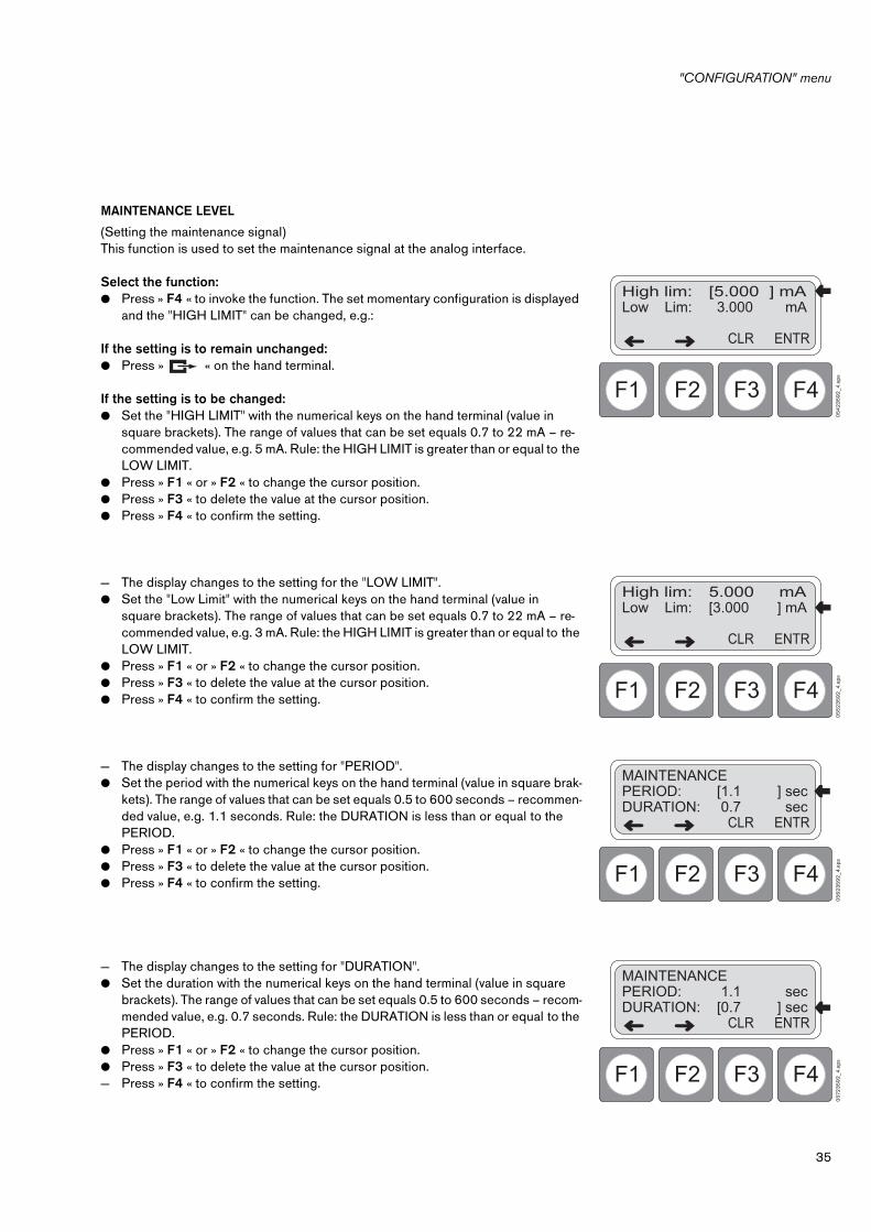
MAINTENANCE LEVEL
(Setting the maintenance signal)This function is used to set the maintenance signal at the analog interface.
Select the function:● Press » F4 « to invoke the function. The set momentary configuration is displayed
and the "HIGH LIMIT" can be changed, e.g.:
If the setting is to remain unchanged:● Press » « on the hand terminal.
If the setting is to be changed:● Set the "HIGH LIMIT" with the numerical keys on the hand terminal (value in
square brackets). The range of values that can be set equals 0.7 to 22 mA – re-commended value, e.g. 5 mA. Rule: the HIGH LIMIT is greater than or equal to the LOW LIMIT.
● Press » F1 « or » F2 « to change the cursor position.● Press » F3 « to delete the value at the cursor position.● Press » F4 « to confirm the setting.
— The display changes to the setting for the "LOW LIMIT".● Set the "Low Limit" with the numerical keys on the hand terminal (value in
square brackets). The range of values that can be set equals 0.7 to 22 mA – re-commended value, e.g. 3 mA. Rule: the HIGH LIMIT is greater than or equal to the LOW LIMIT.
● Press » F1 « or » F2 « to change the cursor position.● Press » F3 « to delete the value at the cursor position.● Press » F4 « to confirm the setting.
— The display changes to the setting for "PERIOD".● Set the period with the numerical keys on the hand terminal (value in square brak-
kets). The range of values that can be set equals 0.5 to 600 seconds – recommen-ded value, e.g. 1.1 seconds. Rule: the DURATION is less than or equal to the PERIOD.
● Press » F1 « or » F2 « to change the cursor position.● Press » F3 « to delete the value at the cursor position.● Press » F4 « to confirm the setting.
— The display changes to the setting for "DURATION".● Set the duration with the numerical keys on the hand terminal (value in square
brackets). The range of values that can be set equals 0.5 to 600 seconds – recom-mended value, e.g. 0.7 seconds. Rule: the DURATION is less than or equal to the PERIOD.
● Press » F1 « or » F2 « to change the cursor position.● Press » F3 « to delete the value at the cursor position.— Press » F4 « to confirm the setting.
F4F3F2F1
High lim: [5.000 ] mALow Lim: 3.000 mA
ENTRCLR
05
42
35
92
_4.e
ps
F4F3F2F1
High lim: 5.000 mALow Lim: [3.000 ] mA
ENTRCLR
05
52
35
92
_4.e
ps
F4F3F2F1
MAINTENANCEPERIOD: [1.1 ] secDURATION: 0.7 sec
ENTRCLR
05
62
35
92
_4.e
ps
F4F3F2F1
MAINTENANCEPERIOD: 1.1 secDURATION: [0.7 ] sec
ENTRCLR
057
23
59
2_4
.eps

"CONFIGURATION" menu
36
COMMUNICATION
This submenu contains all functions with which the most important parameters of the HART interface can be polled and set.
Select the function:● Select the function "COMMUNICATION" in the "CONFIGURATION:" menu.● Press » F3 « to invoke the function. Display:
Selection of functions:» POLLING ADDRESS «» UNIQUE IDENTIFIER «» TAG «
To select a submenu:— Press » F1 «, » F2 « or » F3 « to select one of the submenus.
POLLING ADDRESS
(Configuring the polling address)The gas transmitter is configured for analog operation (4 to 20 mA) or Multidrop operation via the polling address. Analog mode (4 to 20 mA) is activated by setting the polling address " 0 ". The polling address must be set to a value between " 1 " and " 15 " for Multidrop operation. In this case, the analog interface is deactivated and set to a constant current of approx. 1 mA. All gas transmitters connected to a single line must be configured with different polling addresses so that the controller can poll the unique identifier (unique HART address) via the HART command #0. It is advisable to assign polling addresses in consecutive ascending order starting with " 1 ".The setting corresponds to the HART command #6 ("Write polling address").
Select the function:● Press » F1 « to invoke the function. The set momentary configuration is displayed
in the top right-hand corner (value in square brackets), e.g.:
● Press » F1 « (next address) or » F2 « (last address) to change the setting.● Press » F4 « to save the new polling address and end the function.
Important:The function »CONFIGURATION ‡ INITIALISATION ‡ Factory settings« has no effect on the polling address.
F4F3F2F1
COMMUNICATION:
POLL.ADD.
UNI.IDEN
TAG
05
82
35
92
_4.e
ps
F4F3F2F1
Polling Addr.: [00]
NEXTADDR
LASTADDR
ENTR
05
92
35
92
_4.e
ps
37
"CONFIGURATION" menu
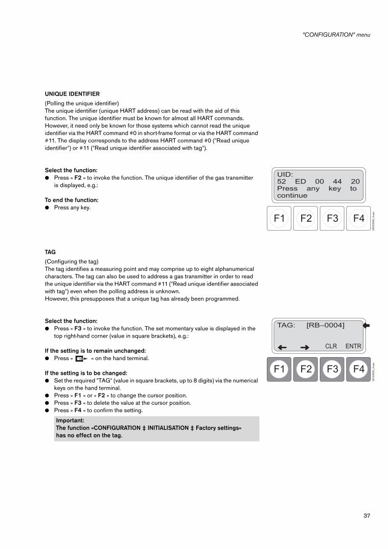
UNIQUE IDENTIFIER
(Polling the unique identifier)The unique identifier (unique HART address) can be read with the aid of this function. The unique identifier must be known for almost all HART commands. However, it need only be known for those systems which cannot read the unique identifier via the HART command #0 in short-frame format or via the HART command #11. The display corresponds to the address HART command #0 ("Read unique identifier") or #11 ("Read unique identifier associated with tag").
Select the function:● Press » F2 « to invoke the function. The unique identifier of the gas transmitter
is displayed, e.g.:
To end the function:● Press any key.
TAG
(Configuring the tag)The tag identifies a measuring point and may comprise up to eight alphanumerical characters. The tag can also be used to address a gas transmitter in order to read the unique identifier via the HART command #11 ("Read unique identifier associated with tag") even when the polling address is unknown.However, this presupposes that a unique tag has already been programmed.
Select the function:● Press » F3 « to invoke the function. The set momentary value is displayed in the
top right-hand corner (value in square brackets), e.g.:
If the setting is to remain unchanged:● Press » « on the hand terminal.
If the setting is to be changed:● Set the required "TAG" (value in square brackets, up to 8 digits) via the numerical
keys on the hand terminal.● Press » F1 « or » F2 « to change the cursor position.● Press » F3 « to delete the value at the cursor position.● Press » F4 « to confirm the setting.
Important:The function »CONFIGURATION ‡ INITIALISATION ‡ Factory settings« has no effect on the tag.
F4F3F2F1
UID:52 ED 00 44 20Press any key tocontinue
06
02
35
92
_4.e
psF4F3F2F1
TAG: [RB–0004]
ENTR CLR
061
23
59
2_4
.eps

"Trim" menu
38
"Trim" menu
The "TRIM" menu contains a number of functions with which the gas transmitter can be calibrated and set up.The "TRIM" menu is made up of a number of submenus and functions. The subme-nus are similarly made up of a number of functions – summary, see Seite 22.
● Press the green » TRIM « key on the hand terminal.— The menu is displayed:
Selection of submenus:» CALIBRATE SENSOR: « » SET ANALOG: « » CALIBRATE ANALOG: «
To select a submenu:— Press » F1 «, » F2 « or » F3 « to select one of the submenus.
CALIBRATE SENSOR
(Perform calibration)This submenu contains all the functions needed for calibrating the gas transmitter.
The gas transmitter must have warmed up before starting calibration !Calibration settings should remain unchanged while the gas transmitter warms up, otherwise the measuring accuracy will be impaired.If calibration is performed during the warm-up phase, it must be repeated when the gas transmitter has warmed up.
If the gas transmitter is operated with a flow cell (accessory part, see Seite 10), the flow cell must be installed before the transmitter is calibrated.
Note the sequence of steps !First check the zero point. If it has to be corrected, check the sensitivity immediately afterwards and adjust it if necessaryNever calibrate the sensitivity before the zero point.
If unforeseen faults occur during the calibration procedure, press » « to abort calibration without changing the former calibration values.
F4F3F2F1
TRIMMING AND SETUP:
SENS.CAL
SETANAL.
CAL.ANAL.
06
22
35
92
_4.e
ps

39
"Trim" menu
Select the function:● Press » F1 « to invoke the function.
— The prompt » ALARM must be Switched Off « is displayed● Press » F4 « to confirm the prompt.
The function is invoked after confirming the prompt. Display:— Press » F1 « or » F2 « to select one of the two functions: » ZERO « (zero point) or» SPAN « (sensitivity).
ZERO
(Calibration of the zero point)When this function is activated, the maintenance signal is output at the 4 to 20 mA interface instead of the concentration.— Nitrogen or synthetic air (containing <50 vpm hydrocarbons) can be used for ca-
librating the zero point.
● Fit the calibration hood (Order No. 68 09 780 for gas transmitters with splash guard) and secure it with the knurled screw, or fit the process / gassing adapter (Order No. 68 09 946 for gas transmitters without splash guard) on the gas trans-mitter and secure it with two screws (see Seite 10).
● Press » F1 « to invoke the function. Display:
● Introduce nitrogen or synthetic air at a flow rate of approx. 1.5 L/min via the cali-bration hood or process / gassing adapter.
● Press » F4 « to confirm. Display:
● Wait for the measured value to stabilize (4 ±1 minutes).
When the measured value has stabilized: press » F4 «.
If calibration is to be aborted:● Press » « on the hand terminal.
F4F3F2F1
ALARMmust be Switched Off
DONE
06
32
35
92
_4.e
ps
F4F3F2F1
CALIBRATE SENSOR
ZEROTRIM
SPAN TRIM
06
42
35
92
_4.e
psF4F3F2F1
APPLY GAS
PRO CEED
06
52
35
92
_4.e
ps
F4F3F2F1
Gas Applied!ACTCONC 0.0 %LELStabilizing value
DONE
067
23
59
2_4
.eps
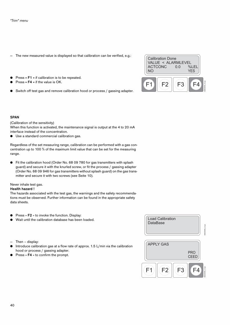
"Trim" menu
40
— The new measured value is displayed so that calibration can be verified, e.g.:
● Press » F1 « if calibration is to be repeated.● Press » F4 « if the value is OK.
● Switch off test gas and remove calibration hood or process / gassing adapter.
SPAN
(Calibration of the sensitivity)When this function is activated, the maintenance signal is output at the 4 to 20 mA interface instead of the concentration.● Use a standard commercial calibration gas.
Regardless of the set measuring range, calibration can be performed with a gas con-centration up to 100 % of the maximum limit value that can be set for the measuring range.
● Fit the calibration hood (Order No. 68 09 780 for gas transmitters with splash guard) and secure it with the knurled screw, or fit the process / gassing adapter (Order No. 68 09 946 for gas transmitters without splash guard) on the gas trans-mitter and secure it with two screws (see Seite 10).
Never inhale test gas.Health hazard !The hazards associated with the test gas, the warnings and the safety recommenda-tions must be observed. Further information can be found in the appropriate safety data sheets.
● Press » F2 « to invoke the function. Display:● Wait until the calibration database has been loaded.
— Then – display:● Introduce calibration gas at a flow rate of approx. 1.5 L/min via the calibration
hood or process / gassing adapter.● Press » F4 « to confirm the prompt.
F4F3F2F1
Calibration DoneVALUE < ALARMLEVELACTCONC 0.0 %LELNO
YES
06
82
35
92
_4.e
ps
Load CalibrationDataBase
06
62
35
92
_4.e
ps
F4F3F2F1
APPLY GAS
PRO CEED
06
52
35
92
_4.e
ps

41
"Trim" menu
The calibration parameters are displayed, e.g.:
● Press » F3 « if the parameters are to be changed.● Press » F4 « if the calibration parameters are OK.
● Wait for the measured value to stabilize (4 ±1 minutes).
● Press » F4 « when the measured value has stabilized.
— Calibration is performed. Display:
— Then – Display:● Switch off the calibration gas.● Press » F4 « (YES) if the measured value has dropped below the alarm threshold.
The 4 to 20 mA interface is reactivated after confirming with "YES"! Ensure that the gas concentration is lower than the alarm threshold set for the sy-stem.
Display:— The calibration data are saved and the function is subsequently ended.
Ensure that the alarm has been reactivated after calibration!
F4F3F2F1
GAS CAL: METHANECALCONC: 24.00 %LELMAX Val: 110.00 %LEL
ENTR CHNG
06
92
35
92
_4.e
ps
F4F3F2F1
Gas Applied!ACTCONC: 27.00 %LEL Stabilizing value
DONE
070
23
59
2_4
.eps
Perform calibration– – – – PLEASE WAIT – – – –
0712
35
92
_4.e
ps
F4F3F2F1
Calibration DoneVALUE < ALARMLEVELACTCONC: 24.00 %LELNO
YES
072
23
59
2_4
.eps
Test Gas RemovedRestore measurementDataBase
073
23
59
2_4
.eps

"Trim" menu
42
SET ANALOG
(Setting the 4 to 20 mA interface)This function is not available if the gas transmitter has been set for Multidrop opera-tion (see Seite 36, Polling Address).
The 4 to 20 mA interface can be checked in combination with the controller via this function group, e.g. to check the alarm triggering.The interface can be set to certain currents between 1 and 22 mA. The configurable special signals for fault, warning and maintenance can also be set.The previous status of the analog interface is restored whenever the function concer-ned is ended.
Alarms, faults or warnings may be activated in the controller by these functions!Alarms must be disabled in the controller beforehand if necessary.
Select the function:● Press » F2 « to invoke the function. Display:— Press » F1 « or » F2 « to select one of the two functions: » 1–22 mA « (set 1 to 22 mA) or» TESTING « (testing the fault, warning, beam block and maintenance signal).
SET 1 – 22 mA
(set 1 to 22 mA)● Press » F1 « to invoke the function.
— The prompt » ALARM must be Switched Off « is displayed.● Press » F4 « to confirm the prompt.
— The submenu is displayed.● The default values (4 mA and 20 mA) are rapidly set via the keys » F1 « or » F2 «.
Press » F1 « – 4 mA at the analog interfacePress » F2 « – 20 mA at the analog interface
— All other values are set via the option » VAL « – press » F3 «.
F4F3F2F1
SET ANALOG
1-22mA
TESTING
074
23
59
2_4
.eps
F4F3F2F1
ALARMmust be Switched Off
DONE
06
32
35
92
_4.e
ps
F4F3F2F1
SET 1 – 22 mA
4 mA 20 mA VAL
075
23
59
2_4
.eps
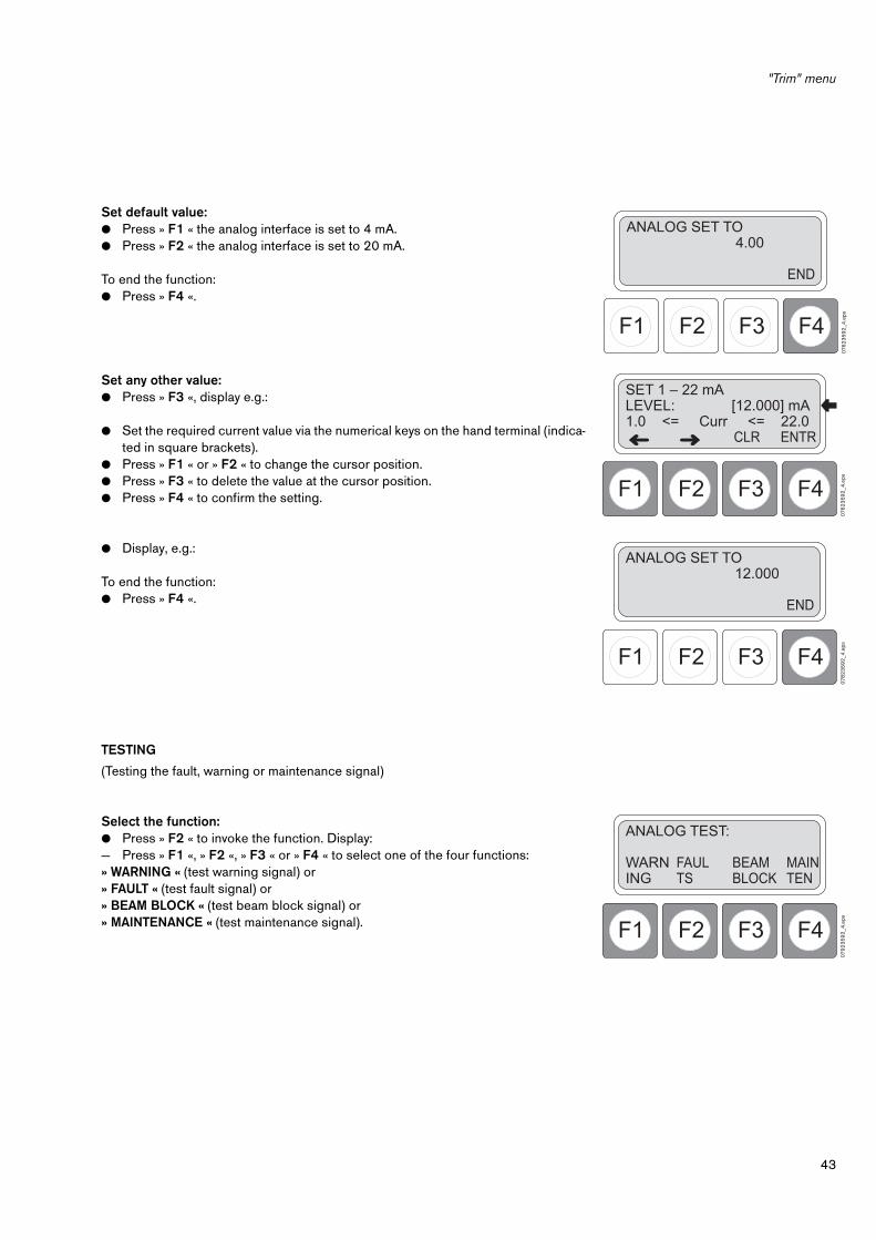
43
"Trim" menu
Set default value:● Press » F1 « the analog interface is set to 4 mA.● Press » F2 « the analog interface is set to 20 mA.
To end the function:● Press » F4 «.
Set any other value:● Press » F3 «, display e.g.:
● Set the required current value via the numerical keys on the hand terminal (indica-ted in square brackets).
● Press » F1 « or » F2 « to change the cursor position.● Press » F3 « to delete the value at the cursor position.● Press » F4 « to confirm the setting.
● Display, e.g.:
To end the function:● Press » F4 «.
TESTING
(Testing the fault, warning or maintenance signal)
Select the function:● Press » F2 « to invoke the function. Display:— Press » F1 «, » F2 «, » F3 « or » F4 « to select one of the four functions:» WARNING « (test warning signal) or» FAULT « (test fault signal) or» BEAM BLOCK « (test beam block signal) or» MAINTENANCE « (test maintenance signal).
F4F3F2F1
ANALOG SET TO 4.00
END
076
23
59
2_4
.eps
F4F3F2F1
SET 1 – 22 mALEVEL: [12.000] mA1.0 <= Curr <= 22.0
ENTRCLR
076
23
59
2_4
.eps
F4F3F2F1
ANALOG SET TO 12.000
END
078
23
59
2_4
.eps
F4F3F2F1
ANALOG TEST:
WARNING
MAINTEN
FAULTS
BEAMBLOCK
079
23
59
2_4
.eps

"Trim" menu
44
– WARNING
(Set warning)● Ensure that the alarm is disabled!● Press » F1 « to invoke the function. Display:— The current configured for warning is output to the analog interface.
To end the function:● Press » F4 «.● Ensure that the alarm is re-enabled!
– FAULT
(Set fault)● Ensure that the alarm is disabled!● Press » F2 « to invoke the function. Display:— The current configured for fault is output to the analog interface.
To end the function:● Press » F4 «.● Ensure that the alarm is re-enabled!
– BEAM BLOCK
(Set beam block)● Ensure that the alarm is disabled!● Press » F3 « to invoke the function. Display:— The current configured for beam block is output to the analog interface.
To end the function:● Press » F4 «.● Ensure that the alarm is re-enabled!
– MAINTENACE
(Set maintenance)● Ensure that the alarm is disabled!● Press » F4 « to invoke the function. Display:— The current configured for maintenance is output to the analog interface.
To end the function:● Press » F4 «.● Ensure that the alarm is re-enabled!
F4F3F2F1
ANALOG SET TOWARNING LEVEL
END
08
02
35
92
_4.e
ps
F4F3F2F1
ANALOG SET TOFAULT
END
081
23
59
2_4
.eps
F4F3F2F1
ANALOG SET TOBEAM BLOCK
END
08
22
35
92
_4.e
ps
F4F3F2F1
ANALOG SET TOMAINTENANCE
END
08
32
35
92
_4.e
ps
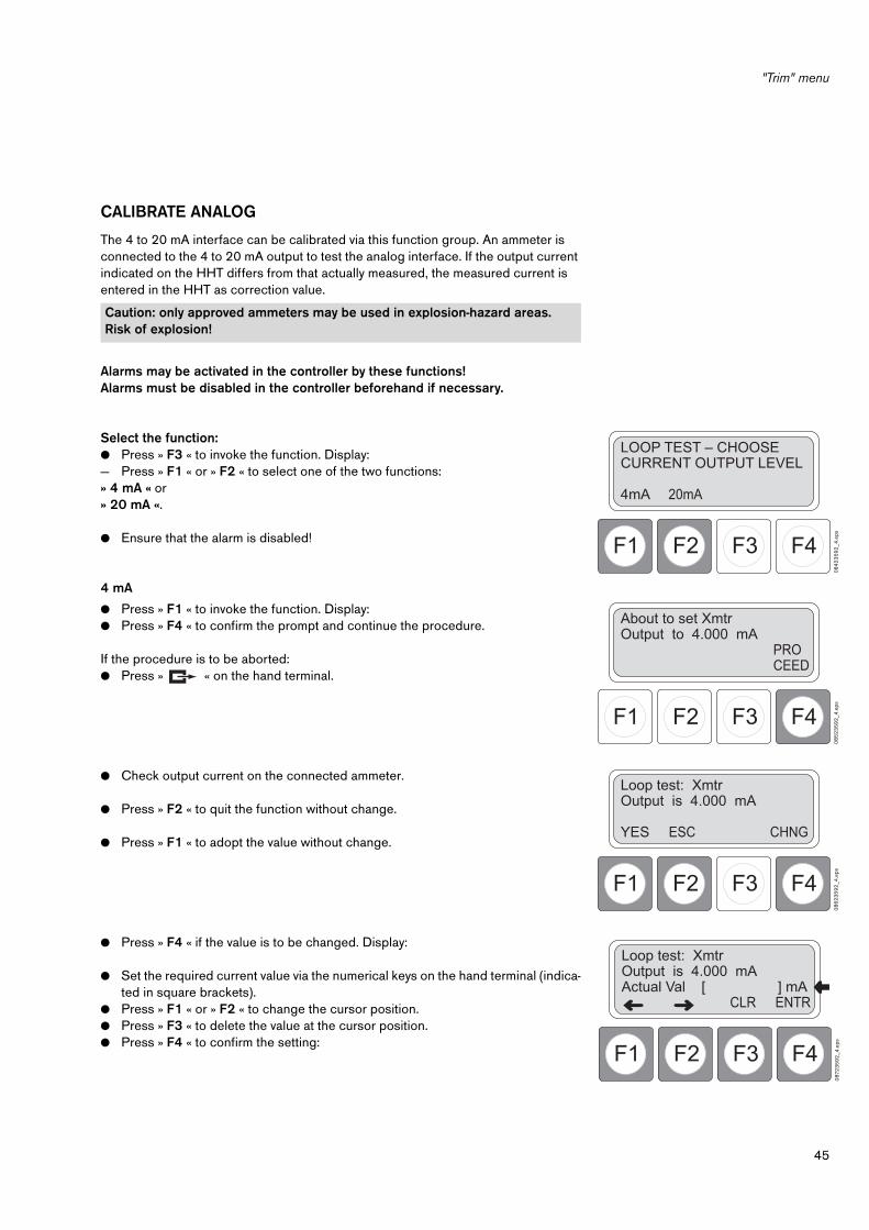
45
"Trim" menu
CALIBRATE ANALOG
The 4 to 20 mA interface can be calibrated via this function group. An ammeter is connected to the 4 to 20 mA output to test the analog interface. If the output current indicated on the HHT differs from that actually measured, the measured current is entered in the HHT as correction value.
Alarms may be activated in the controller by these functions!Alarms must be disabled in the controller beforehand if necessary.
Select the function:● Press » F3 « to invoke the function. Display:— Press » F1 « or » F2 « to select one of the two functions: » 4 mA « or» 20 mA «.
● Ensure that the alarm is disabled!
4 mA
● Press » F1 « to invoke the function. Display:● Press » F4 « to confirm the prompt and continue the procedure.
If the procedure is to be aborted:● Press » « on the hand terminal.
● Check output current on the connected ammeter.
● Press » F2 « to quit the function without change.
● Press » F1 « to adopt the value without change.
● Press » F4 « if the value is to be changed. Display:
● Set the required current value via the numerical keys on the hand terminal (indica-ted in square brackets).
● Press » F1 « or » F2 « to change the cursor position.● Press » F3 « to delete the value at the cursor position.● Press » F4 « to confirm the setting:
Caution: only approved ammeters may be used in explosion-hazard areas. Risk of explosion!
F4F3F2F1
LOOP TEST – CHOOSECURRENT OUTPUT LEVEL
4mA 20mA
08
42
35
92
_4.e
ps
F4F3F2F1
About to set XmtrOutput to 4.000 mA
PROCEED
08
52
35
92
_4.e
ps
F4F3F2F1
Loop test: XmtrOutput is 4.000 mA
YES ESC CHNG
08
62
35
92
_4.e
ps
F4F3F2F1
Loop test: XmtrOutput is 4.000 mAActual Val [ ] mA
ENTRCLR
087
23
59
2_4
.eps

"Trim" menu
46
● Press » F1 « if the set value is correct.
● Ensure that the alarm is re-enabled after changing the value!
20 mA
● Press » F2 « to invoke the function. Display:
● Same procedure as described for the function » 4 mA «, Seite 45.
F4F3F2F1
Loop test: XmtrOutput is 4.200 mA
YES CHNGESC
08
82
35
92
_4.e
ps
F4F3F2F1
About to set XmtrOutput to 20.000 mA
PROCEED
08
92
35
92
_4.e
ps

47
Technical data
Technical data
Principle of operation Dual compensated infrared absorption, non-imaging optics
Measuring range 0 to 100 % LEL, other measuring ranges and measuring units can be configured
Standard measuring gases
– Type 334 Methane, gases and vapours listed in the table on Seite 50, other substances on request
– Type 340 Propane, gases and vapours listed in the table on Seite 51, other substances on request
Signal transmission to the central controller
Analog:
– Measuring current 4 mA to 20 mA
– Underrange 3.8 mA to 4 mA
– Overrange 20 mA to 20.5 mA
– Fault signal <1.2 mA
– Maintenance signal 4 mA ±1 mA, every 1.1 seconds (configurable)
Switchable options:
– Warning signal Fault signal for 0.7 seconds every 10 seconds, measuring signal in between
– Beam block warning 2 mA for measured value < 15 % LEL, otherwise measured value
Digital: HART interface (semi-duplex)RS 485 interface (semi-duplex)
Supply voltage 15 V DC to 30 V DC
– AC component <0.5 Vss for analog 4 to 20 mA signal transmission
<0.2 Vss and
<2.2 mVeff (500 to 10 000 Hz) for digital HART communication
Power consumption <5 W
Connecting thread 3/4" NPT (UL version), M 25 x 1.5 (CENELEC version)
Material Stainless steel SS 316
Weight Approx. 3.1 kg
Dimensions 125 mm x 180 mm x 155 mm
Ambient conditions
Operation –40 to 65 oC–40 to 60 oC only for IECEx version–55 to 65 oC in accordance with CSA certificate700 to 1300 hPa0 to 100 % rel. humidity
Storage –40 to 70 oC700 to 1300 hPa, 0 to 100 % rel. humidity, without condensation

Technical data
48
1) The year of manufacture is indicated by the third letter in the serial number shown on the rating plate: T = 2003, U = 2004, W = 2005,X = 2006, Y = 2007, Z = 2008, A = 2009, B = 2010, C = 2011, etc.Example: Serial No. ARUH-0054: the third letter is U, which means that the unit was manufactured in 2004.
Type of protection IP 66 and IP 67, Nema 4 & 7
CE marking Equipment and protective systems for use in potentially explosive atmospheres (Directive 94/9/EC); CENELEC version only
Explosion protection:
ATEX / IECEx Polytron 2 IR
0158
II 2G EEx de [ia] IIC T5II 2D IP6X T100 oCDMT 97 ATEX 003 XEx de [ia] IIC T5DIP A21 IR6X T100oCIECEx BVS 06.0002 XUn = 15 ... 30 VDCUm = 250 V–40oC ≤ Ta ≤ +65oC (ATEX), –40oC ≤ Ta ≤ +60oC (IECEx)Uo = 1,5 V, Io = 88,2 mA, Po = 33 mWUi = 10 V, Ii = 1 A, Pi = 50 mW, Ci = 0, Li = 0Warning: Do not open when energized!Dräger Safety, 23560 Lübeck, GermanySerial No. 1)
Refer to the special conditions for safe use contained in the EC type-test certificate.The installation regulations (EN 50281-1-2) must be observed with respect to possible deposits of explosive dust.The 4 to 20 mA analog output meets the requirements for devices with measuring function for explosion protection in accordance with Directive 94/9/EC, Annex II, 1.5.5 to 1.5.7. for the measuring range 0 to 100 % LEL
UL Class I, Div. 1, Groups B, C, D(File E186298)
CSA Class I, Div. 1, Groups B, C, DCertificate No. LR 97594-25
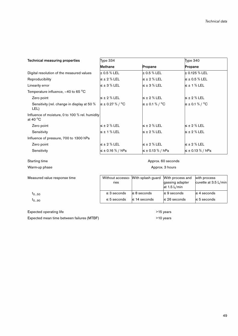
49
Technical data
Technical measuring properties Type 334 Type 340
Methane Propane Propane
Digital resolution of the measured values ± 0.5 % LEL ± 0.5 % LEL ± 0.125 % LEL
Reproducibility ≤ ± 2 % LEL ≤ ± 2 % LEL ≤ ± 0.5 % LEL
Linearity error ≤ ± 3 % LEL ≤ ± 3 % LEL ≤ ± 1 % LEL
Temperature influence, –40 to 65 oC
Zero point ≤ ± 2 % LEL ≤ ± 2 % LEL ≤ ± 2 % LEL
Sensitivity (rel. change in display at 50 % LEL)
≤ ± 0.27 % / oC ≤ ± 0.1 % / oC ≤ ± 0.1 % / oC
Influence of moisture, 0 to 100 % rel. humidity at 40 oC
Zero point ≤ ± 2 % LEL ≤ ± 2 % LEL ≤ ± 2 % LEL
Sensitivity ≤ ± 1 % LEL ≤ ± 2 % LEL ≤ ± 2 % LEL
Influence of pressure, 700 to 1300 hPa
Zero point ≤ ± 2 % LEL ≤ ± 2 % LEL ≤ ± 2 % LEL
Sensitivity ≤ ± 0.16 % / hPa ≤ ± 0.13 % / hPa ≤ ± 0.13 % / hPa
Starting time Approx. 60 seconds
Warm-up phase Approx. 3 hours
Measured value response time Without accesso-ries
With splash guard With process and gassing adapter at 1.5 L/min
with process cuvette at 3.5 L/min
t0...50 ≤ 3 seconds ≤ 8 seconds ≤ 9 seconds ≤ 4 seconds
t0...90 ≤ 5 seconds ≤ 14 seconds ≤ 26 seconds ≤ 5 seconds
Expected operating life >15 years
Expected mean time between failures (MTBF) >10 years
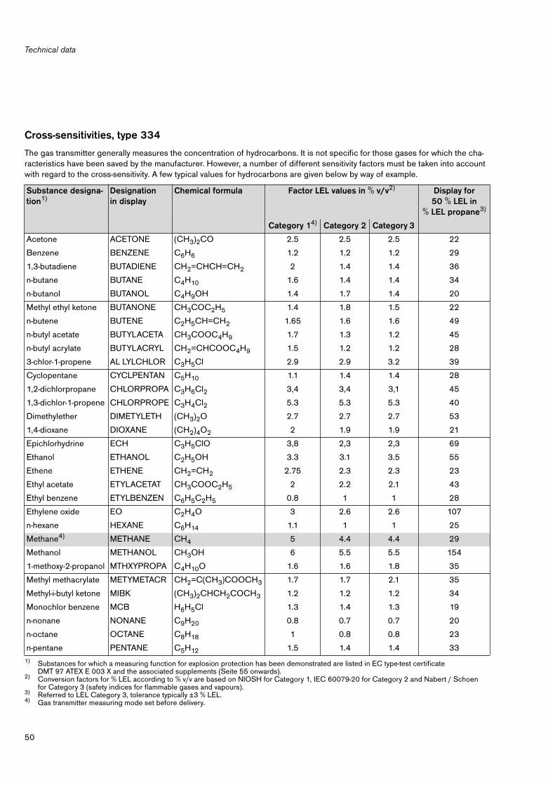
Technical data
50
Cross-sensitivities, type 334
The gas transmitter generally measures the concentration of hydrocarbons. It is not specific for those gases for which the cha-racteristics have been saved by the manufacturer. However, a number of different sensitivity factors must be taken into account with regard to the cross-sensitivity. A few typical values for hydrocarbons are given below by way of example.
Substance designa-tion1)
1) Substances for which a measuring function for explosion protection has been demonstrated are listed in EC type-test certificate DMT 97 ATEX E 003 X and the associated supplements (Seite 55 onwards).
Designation in display
Chemical formula Factor LEL values in % v/v2)
2) Conversion factors for % LEL according to % v/v are based on NIOSH for Category 1, IEC 60079-20 for Category 2 and Nabert / Schoen for Category 3 (safety indices for flammable gases and vapours).
Display for 50 % LEL in
% LEL propane3)
3) Referred to LEL Category 3, tolerance typically ±3 % LEL.
Category 14)
4) Gas transmitter measuring mode set before delivery.
Category 2 Category 3
Acetone ACETONE (CH3)2CO 2.5 2.5 2.5 22
Benzene BENZENE C6H6 1.2 1.2 1.2 29
1,3-butadiene BUTADIENE CH2=CHCH=CH2 2 1.4 1.4 36
n-butane BUTANE C4H10 1.6 1.4 1.4 34
n-butanol BUTANOL C4H9OH 1.4 1.7 1.4 20
Methyl ethyl ketone BUTANONE CH3COC2H5 1.4 1.8 1.5 22
n-butene BUTENE C2H5CH=CH2 1.65 1.6 1.6 49
n-butyl acetate BUTYLACETA CH3COOC4H9 1.7 1.3 1.2 45
n-butyl acrylate BUTYLACRYL CH2=CHCOOC4H9 1.5 1.2 1.2 28
3-chlor-1-propene AL LYLCHLOR C3H5Cl 2.9 2.9 3.2 39
Cyclopentane CYCLPENTAN C5H10 1.1 1.4 1.4 28
1,2-dichlorpropane CHLORPROPA C3H6Cl2 3,4 3,4 3,1 45
1,3-dichlor-1-propene CHLORPROPE C3H4Cl2 5.3 5.3 5.3 40
Dimethylether DIMETYLETH (CH3)2O 2.7 2.7 2.7 53
1,4-dioxane DIOXANE (CH2)4O2 2 1.9 1.9 21
Epichlorhydrine ECH C3H5ClO 3,8 2,3 2,3 69
Ethanol ETHANOL C2H5OH 3.3 3.1 3.5 55
Ethene ETHENE CH2=CH2 2.75 2.3 2.3 23
Ethyl acetate ETYLACETAT CH3COOC2H5 2 2.2 2.1 43
Ethyl benzene ETYLBENZEN C6H5C2H5 0.8 1 1 28
Ethylene oxide EO C2H4O 3 2.6 2.6 107
n-hexane HEXANE C6H14 1.1 1 1 25
Methane4) METHANE CH4 5 4.4 4.4 29
Methanol METHANOL CH3OH 6 5.5 5.5 154
1-methoxy-2-propanol MTHXYPROPA C4H10O 1.6 1.6 1.8 35
Methyl methacrylate METYMETACR CH2=C(CH3)COOCH3 1.7 1.7 2.1 35
Methyl-i-butyl ketone MIBK (CH3)2CHCH2COCH3 1.2 1.2 1.2 34
Monochlor benzene MCB H6H5Cl 1.3 1.4 1.3 19
n-nonane NONANE C9H20 0.8 0.7 0.7 20
n-octane OCTANE C8H18 1 0.8 0.8 23
n-pentane PENTANE C5H12 1.5 1.4 1.4 33

51
Technical data
Cross-sensitivities, type 340
The gas transmitter generally measures the concentration of hydrocarbons. It is not specific for those gases for which the cha-racteristics have been saved by the manufacturer. However, a number of different sensitivity factors must be taken into account with regard to the cross-sensitivity. A few typical values for hydrocarbons are given below by way of example.
Substance designation1)
Designation in display
Chemical formula Factor LEL values in % v/v2) Display for 50 % LEL in
% LEL propane 3)
Category 14) Category 2 Category 3
Propane PROPANE C3H8 2.1 1.7 1.7 50
i-propanol PROPANOL (CH3)2CHOH 2 2 2 33
Propene PROPENE CH2=CHCH3 2 2 2 43
Propylen oxide PO C3H6O 2.3 1.9 1.9 62
Styrene STYRENE C8H8 0.9 1.1 0.97 43
Toluene TOLUENE C6H5CH3 1.1 1.1 1.2 34
o-xylene XYLENE C6H4(CH3)2 0.9 1 1 25
Substance desi-gnation1)
1) Substances for which a measuring function for explosion protection has been demonstrated are listed in EC type-test certificate DMT 97 ATEX E 003 X and the associated supplements (Seite 55 onwards).
Designation in display
Chemical formula Factor LEL values in % v/v2)
2) Conversion factors for % LEL according to % v/v are based on NIOSH for Category 1, IEC 60079-20 for Category 2 and Nabert / Schoen for Category 3 (safety indices for flammable gases and vapours).
Display for 50 % LEL in
% LEL propane3)
3) Referred to LEL Category 3, tolerance typically ±3 % LEL.
Category 14)
4) Gas transmitter measuring mode set before delivery.
Category 2 Category 3
n-butane BUTANE C4H10 1.6 1.4 1.4 53
Cyclopentane C-PENTANE C5H10 1.1 1.4 1.4 55
Cyclohexane C-HEXANE C6H12 1.3 1.2 1.2 40
1,2-dichloroethane EDC C2H4Cl2 6.2 6.2 6.2 13
Diethylether ETHYLETHER (C2H5)2O 1.9 1.7 1.7 51
n-hexane HEXANE C6H14 1.1 1.0 1.0 50
Methane METHANE CH4 5.0 4.4 4.4 8
Methyl chloride METHYL-CL CH3Cl 8.1 7.6 7.6 23
Methyl-tert-butyl ether
MTBE CH3OC(CH3)3 1.5 1.5 1.6 52
n-nonane NONANE C9H20 0.8 0.7 0.7 41
n-octane OCTANE C8H18 1.0 0.8 0.8 48
n-pentane PENTANE C5H12 1.5 1.4 1.4 63
Propane4) PROPANE C3H8 2.1 1.7 1.7 50
Tetrahydrofurane THF (CH2)4O 2.0 1.5 1.5 43
Toluene TOLUENE C6H5CH3 1.1 1.1 1.2 9
o-xylene XYLENE C6H4(CH3)2 0.9 1.0 1.0 14

Technical data
52
Dimensions
010
23
59
2_4
.epsØ 124
51.5
139
171
61.5

53
Design and principle of operation
Design and principle of operation
The Dräger Polytron IR gas transmitter is a transducer for measuring the concentra-tion of hydrocarbons in the atmosphere by absorbing infrared radiation.
The infrared technology differs from other processes in the following ways:— Unambiguous indication of concentrations above the lower explosion limit,— Less maintenance effort due to better long-term stability,— Fail-safe,— Insensitive to the rate of flow,— Insensitive to polymerizing and corrosive substances and catalyst poisons,— Unrestricted sensitivity in low-oxygen and oxygen-free mixtures,— No detection of ethine, hydrogen and carbon disulphide.
Microprocessor technology permits:— Identification of equipment faults and warnings via the display and current inter-
face,— Special calibration mode to suppress alarms in the controller during maintenance
work (one-man calibration),— Individual linearization of the display for all measured gases,— Temperature compensation,— Unit of measurement can be selected for the display,— Freely selectable measuring range.
The ambient air to be monitored is entrained into the cuvette by a thermally induced updraft.An infrared emitter L1 generates a wideband modulated beam (visible components can be seen to flash). The beam emerges from the housing through an exit aperture and passes through the cuvette twice. The plane-parallel mirror S reflects the beam which is diverted to the detectors D1 and D2 in the optical module. The cuvette is heated to prevent condensation of the moisture contained in the atmosphere.
The beam is absorbed at the measuring wavelength on account of hydrocarbon com-ponents in the atmosphere, thus causing the signal at detector D1 to decrease. The stability of the zero point is guaranteed by a reference detector D2 which compensa-tes the effects of dirt on the mirror and window, as well as fluctuations in the inten-sity of the infrared emitter.
A second internal emitter L2 compensates thermal drifts and ageing by the two detectors or lamps. Together, these two compensation processes ensure maximum stability.
0112
35
92
_4.e
ps
L1L2
D1
D2
S

Order list
54
Order list
Designation and description Order No.
Dräger Polytron IR – Type 334 ULInfrared gas transmitter3/4" NPT connecting thread
68 10 098
Dräger Polytron IR – Type 334 CENELEC Infrared gas transmitter, M 25 x 1.5 connecting thread
68 10 100
Dräger Polytron IR – Type 334 CENELEC complete set1)
Infrared gas transmitter connecting thread M 25 x 1.5
1) The complete set includes the terminal box, the splash guard as well as the assembly set, already preassembled.
83 15 629
Dräger Polytron IR Type 334 IECEx Infrared gas transmitter connecting thread M 25 x 1.5
68 11 650
Dräger Polytron IR Type 334 IECEx complete set1)
Infrared gas transmitter connecting thread M 25 x 1.568 11 635
Dräger Polytron IR – Type 340 ULInfrared gas transmitter3/4" NPT connecting thread
68 10 820
Dräger Polytron IR – Type 340 CENELEC Infrared gas transmitter, M 25 x 1.5 connecting thread
68 10 760
Dräger Polytron IR – Type 340 CENELEC complete set1)
Infrared gas transmitter connecting thread M 25 x 1,583 18 590
Dräger Polytron IR Type 340 IECEx Infrared gas transmitter connecting thread M 25 x 1,5
68 11 640
Dräger Polytron IR Type 340 IECEx complete set1)
Infrared gas transmitter connecting thread M 25 x 1,583 11 645
Accessories:
Dräger Polytron IR splash guard 68 09 750
Dräger Polytron IR calibration adapter 68 09 780
Dräger Polytron IR flow cell 68 09 450
Dräger Polytron IR gasing / process adapter 68 09 946
Dräger Polytron IR process cuvette 68 10 780
Dräger PRC 3000, remote control software 83 18 906
Dräger Polytron IR remote test adapter 68 10 985
Dräger Polytron IR insect protection 68 10 162
Dräger Polytron IR hydrophobic filter 68 10 519
Assembly set 68 09 951
Handheld terminal ABB 691 (FM approval) complete set2)
2) The complete set includes the battery pack and a short operating manual.
83 17 560
Handheld terminal ABB 691 (ATEX approval) complete set2) 83 17 530
Charger for handheld terminal ABB 691 83 17 532
Dräger Polytron IR adapter cable for handheld terminal 83 15 437
Dräger Polytron IR terminal box HHT-T 83 15 083
Dräger Polytron IR terminal box HHT-H 83 15 137

55
CENELEC approval
CENELEC approval

CENELEC approval
56
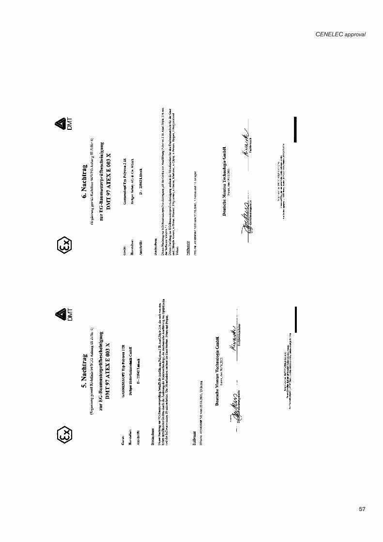
57
CENELEC approval

CENELEC approval
58

59
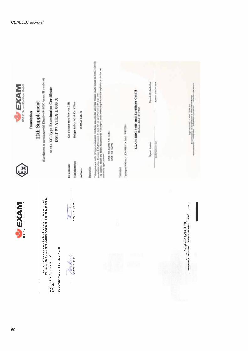
CENELEC approval
60
61
CENELEC approval
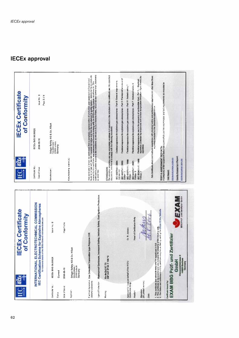
IECEx approval
62
IECEx approval
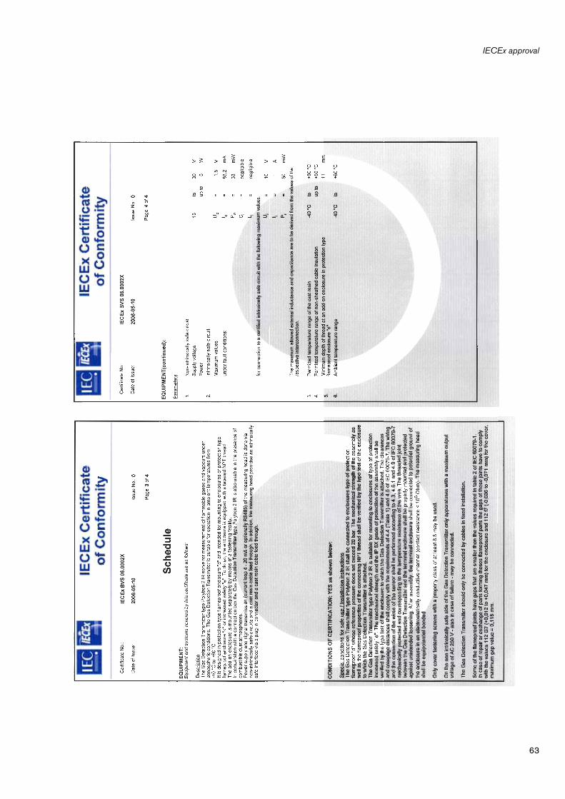
63
IECEx approval

UL approval
64
UL approval

65
UL approval
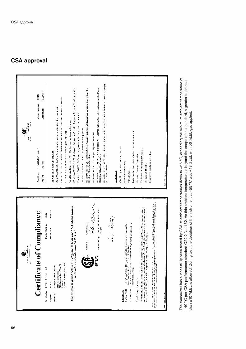
CSA approval
66
CSA approval
The
tran
smitt
er h
as s
ucce
ssfu
lly b
een
test
ed b
y C
SA
at a
mbi
ent t
empe
ratu
res
dow
n to
–5
5 o C
, exc
eedi
ng th
e m
inim
um a
mbi
ent t
empe
ratu
re o
f–
40
o C p
er C
SA
per
form
ance
sta
ndar
d C
22
.2 N
o. 1
52
. As
this
am
bien
t tem
pera
ture
is b
eyon
d th
e sc
ope
of th
e st
anda
rd, a
gre
ater
tole
ranc
e th
an ±
10 %
LEL
is a
llow
ed. D
urin
g te
st, t
he d
evia
tion
of th
e in
stru
men
t at –
55
o C w
as +
13 %
LEL
with
50
%LE
L ga
s ap
plie
d.
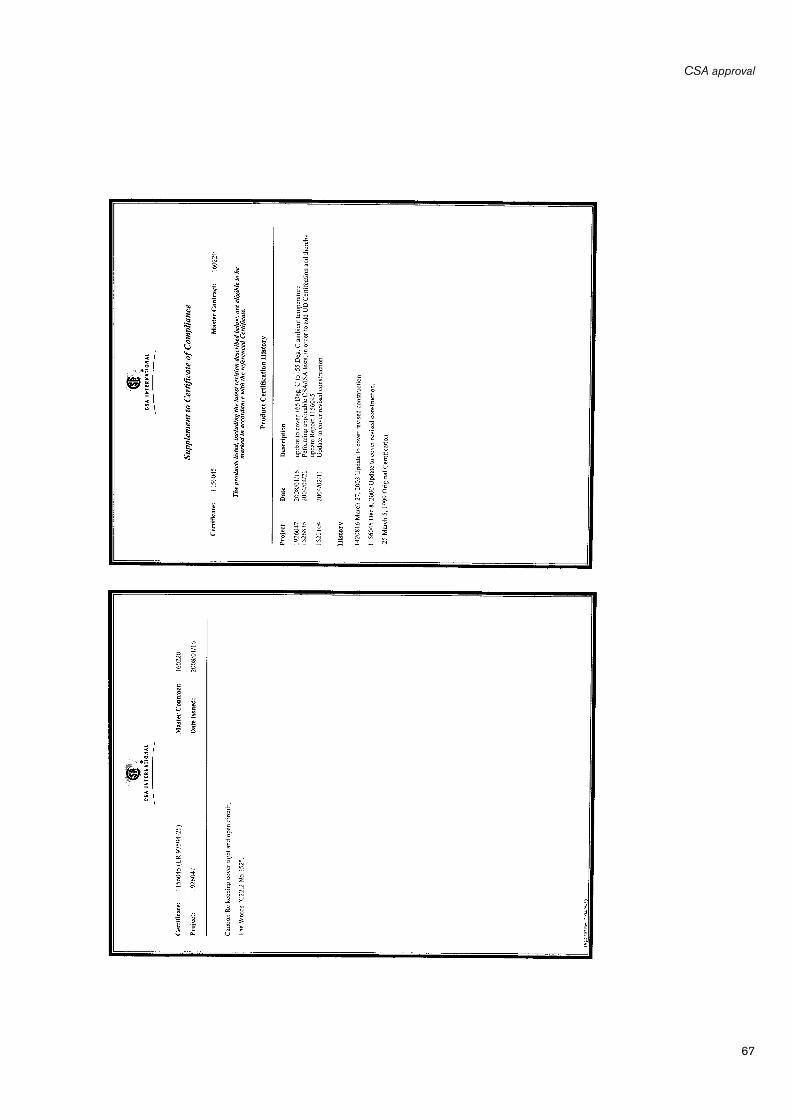
67
CSA approval
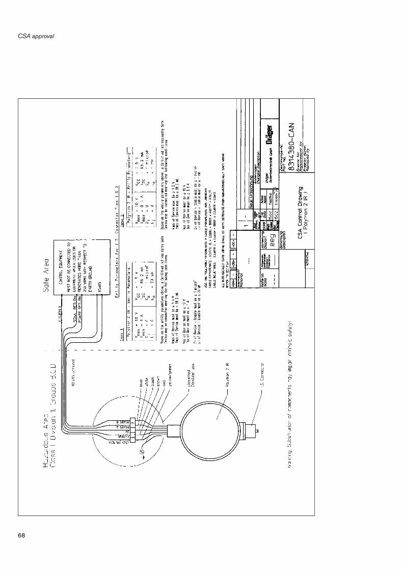
CSA approval
68

69
Declaration of conformity
Declaration of conformity

Index
70
Index
"CONFIGURATION" menu . . . . . . . . . . . . . . . . . . . . . . . . . . . . . . . . . . . . . . . . . . . . . 27"PV" menu (Dynamic Var) . . . . . . . . . . . . . . . . . . . . . . . . . . . . . . . . . . . . . . . . . . . . . . 23"REVIEW" menu . . . . . . . . . . . . . . . . . . . . . . . . . . . . . . . . . . . . . . . . . . . . . . . . . . . . . . 24"Trim" menu . . . . . . . . . . . . . . . . . . . . . . . . . . . . . . . . . . . . . . . . . . . . . . . . . . . . . . . . . . 38
Accessories . . . . . . . . . . . . . . . . . . . . . . . . . . . . . . . . . . . . . . . . . . . . . . . . . . . . . . . . . . 54Air flow conditions . . . . . . . . . . . . . . . . . . . . . . . . . . . . . . . . . . . . . . . . . . . . . . . . . . . . . . 6Ambient conditions . . . . . . . . . . . . . . . . . . . . . . . . . . . . . . . . . . . . . . . . . . . . . . . . . . . 47Approval for use in hazardous areas . . . . . . . . . . . . . . . . . . . . . . . . . . . . . . . . . . . . . . . 5
Beam block warning . . . . . . . . . . . . . . . . . . . . . . . . . . . . . . . . . . . . . . . . . . . . . . . . . . 15
CALIBRATE ANALOG . . . . . . . . . . . . . . . . . . . . . . . . . . . . . . . . . . . . . . . . . . . . . . . . 45CALIBRATE SENSOR . . . . . . . . . . . . . . . . . . . . . . . . . . . . . . . . . . . . . . . . . . . . . . . . 38Calibration hood . . . . . . . . . . . . . . . . . . . . . . . . . . . . . . . . . . . . . . . . . . . . . . . . . . . . . . 12Calibration interval . . . . . . . . . . . . . . . . . . . . . . . . . . . . . . . . . . . . . . . . . . . . . . . . . . . . 17CALIBRATION PARAM. . . . . . . . . . . . . . . . . . . . . . . . . . . . . . . . . . . . . . . . . . . . . . . . 31CE marking . . . . . . . . . . . . . . . . . . . . . . . . . . . . . . . . . . . . . . . . . . . . . . . . . . . . . . . . . . 48CENELEC approval . . . . . . . . . . . . . . . . . . . . . . . . . . . . . . . . . . . . . . . . . . . . . . . . 5, 55CENELEC-Zulassung . . . . . . . . . . . . . . . . . . . . . . . . . . . . . . . . . . . . . . . . . . . . . . . . . 48Central controller . . . . . . . . . . . . . . . . . . . . . . . . . . . . . . . . . . . . . . . . . . . . . . . . . . . . . . . 5Checking and cleaning the cuvette . . . . . . . . . . . . . . . . . . . . . . . . . . . . . . . . . . . . . . 18Colour-coding of the conductors . . . . . . . . . . . . . . . . . . . . . . . . . . . . . . . . . . . . . . . . . . 8COMMUNICATION . . . . . . . . . . . . . . . . . . . . . . . . . . . . . . . . . . . . . . . . . . . . . . . . . . . 36Condition on delivery . . . . . . . . . . . . . . . . . . . . . . . . . . . . . . . . . . . . . . . . . . . . . . . . . . 14Configuration . . . . . . . . . . . . . . . . . . . . . . . . . . . . . . . . . . . . . . . . . . . . . . . . . . . . . . . . 14Configuring the calibration gas . . . . . . . . . . . . . . . . . . . . . . . . . . . . . . . . . . . . . . . . . 14Configuring the concentration . . . . . . . . . . . . . . . . . . . . . . . . . . . . . . . . . . . . . . . . . . 14Configuring the gas transmitter . . . . . . . . . . . . . . . . . . . . . . . . . . . . . . . . . . . . . . . . . 14Configuring the type of gas . . . . . . . . . . . . . . . . . . . . . . . . . . . . . . . . . . . . . . . . . . . . 14Connecting the hand terminal . . . . . . . . . . . . . . . . . . . . . . . . . . . . . . . . . . . . . . . . . . 20Conversion factor . . . . . . . . . . . . . . . . . . . . . . . . . . . . . . . . . . . . . . . . . . . . . . . . . 50, 51Cross-sensitivities . . . . . . . . . . . . . . . . . . . . . . . . . . . . . . . . . . . . . . . . . . . . . . . . . 50, 51CSA approval . . . . . . . . . . . . . . . . . . . . . . . . . . . . . . . . . . . . . . . . . . . . . . . . 5, 48, 66
Declaration of conformity . . . . . . . . . . . . . . . . . . . . . . . . . . . . . . . . . . . . . . . . . . . . . . 69Design and principle of operation . . . . . . . . . . . . . . . . . . . . . . . . . . . . . . . . . . . . . . . 53DIAGNOSTIC . . . . . . . . . . . . . . . . . . . . . . . . . . . . . . . . . . . . . . . . . . . . . . . . . . . . . . . . 24Dimensions . . . . . . . . . . . . . . . . . . . . . . . . . . . . . . . . . . . . . . . . . . . . . . . . . . . . . . . . . . 52Dräger Controller Regard HART card . . . . . . . . . . . . . . . . . . . . . . . . . . . . . . . . . . . . 16Dräger Polytron IR adapter lead . . . . . . . . . . . . . . . . . . . . . . . . . . . . . . . . . . . . . 16, 20
Electrical installation . . . . . . . . . . . . . . . . . . . . . . . . . . . . . . . . . . . . . . . . . . . . . . . . . . . . 8Explosion protection . . . . . . . . . . . . . . . . . . . . . . . . . . . . . . . . . . . . . . . . . . . . . . . . . . 48Explosion-hazard areas . . . . . . . . . . . . . . . . . . . . . . . . . . . . . . . . . . . . . . . . . . . . . . . . . . 4
71
Index
Fault, cause, remedy . . . . . . . . . . . . . . . . . . . . . . . . . . . . . . . . . . . . . . . . . . . . . . . . . . . 19Flow cell . . . . . . . . . . . . . . . . . . . . . . . . . . . . . . . . . . . . . . . . . . . . . . . . . . . . . . . . . . . . . 10
GAS + RANGE . . . . . . . . . . . . . . . . . . . . . . . . . . . . . . . . . . . . . . . . . . . . . . . . . . . . . . . 30
Hand terminal ABB 691 HT . . . . . . . . . . . . . . . . . . . . . . . . . . . . . . . . . . . . . . . . . . . . . 20HART-Multidrop . . . . . . . . . . . . . . . . . . . . . . . . . . . . . . . . . . . . . . . . . . . . . . . . . . . . . . . . 8
IECEx approval . . . . . . . . . . . . . . . . . . . . . . . . . . . . . . . . . . . . . . . . . . . . . . . . . . . . . . . 62Impedance . . . . . . . . . . . . . . . . . . . . . . . . . . . . . . . . . . . . . . . . . . . . . . . . . . . . . . . . . . . . 8Increased safety (EEx e) . . . . . . . . . . . . . . . . . . . . . . . . . . . . . . . . . . . . . . . . . . . . . . . . . 7Influence of moisture . . . . . . . . . . . . . . . . . . . . . . . . . . . . . . . . . . . . . . . . . . . . . . . . . . 49Influence of pressure . . . . . . . . . . . . . . . . . . . . . . . . . . . . . . . . . . . . . . . . . . . . . . . . . . 49Infrared technology . . . . . . . . . . . . . . . . . . . . . . . . . . . . . . . . . . . . . . . . . . . . . . . . . . . . 53INITIALISATION . . . . . . . . . . . . . . . . . . . . . . . . . . . . . . . . . . . . . . . . . . . . . . . . . . . . . . 28Inspection . . . . . . . . . . . . . . . . . . . . . . . . . . . . . . . . . . . . . . . . . . . . . . . . . . . . . . . . . . . . 17Installation . . . . . . . . . . . . . . . . . . . . . . . . . . . . . . . . . . . . . . . . . . . . . . . . . . . . . . . . . . . . 6Installation in protective tubing . . . . . . . . . . . . . . . . . . . . . . . . . . . . . . . . . . . . . . . . . . . 8Installation site . . . . . . . . . . . . . . . . . . . . . . . . . . . . . . . . . . . . . . . . . . . . . . . . . . . . . . . . . 6Installing accessories . . . . . . . . . . . . . . . . . . . . . . . . . . . . . . . . . . . . . . . . . . . . . . . . . . 10Intended use . . . . . . . . . . . . . . . . . . . . . . . . . . . . . . . . . . . . . . . . . . . . . . . . . . . . . . . . . . 5
Liability . . . . . . . . . . . . . . . . . . . . . . . . . . . . . . . . . . . . . . . . . . . . . . . . . . . . . . . . . . . . . . . 4Linearity error . . . . . . . . . . . . . . . . . . . . . . . . . . . . . . . . . . . . . . . . . . . . . . . . . . . . . . . . . 49Llinking up with the gas transmitter . . . . . . . . . . . . . . . . . . . . . . . . . . . . . . . . . . . . . . 21
Maintenance . . . . . . . . . . . . . . . . . . . . . . . . . . . . . . . . . . . . . . . . . . . . . . . . . . . . . . . . . . 17Maintenance intervals . . . . . . . . . . . . . . . . . . . . . . . . . . . . . . . . . . . . . . . . . . . . . . . . . . 17Measured value response time . . . . . . . . . . . . . . . . . . . . . . . . . . . . . . . . . . . . . . . . . . 49Measurement . . . . . . . . . . . . . . . . . . . . . . . . . . . . . . . . . . . . . . . . . . . . . . . . . . . . . . . . . 16MEASUREMENT TYPE . . . . . . . . . . . . . . . . . . . . . . . . . . . . . . . . . . . . . . . . . . . . . . . . 23Measuring range . . . . . . . . . . . . . . . . . . . . . . . . . . . . . . . . . . . . . . . . . . . . . . . . . . . . . . 47Mechanical installation . . . . . . . . . . . . . . . . . . . . . . . . . . . . . . . . . . . . . . . . . . . . . . . . . . 7Menu structure . . . . . . . . . . . . . . . . . . . . . . . . . . . . . . . . . . . . . . . . . . . . . . . . . . . . . . . . 22Messbereich . . . . . . . . . . . . . . . . . . . . . . . . . . . . . . . . . . . . . . . . . . . . . . . . . . . . . . . . . . 5Method of operation . . . . . . . . . . . . . . . . . . . . . . . . . . . . . . . . . . . . . . . . . . . . . . . . . . . 20Microprocessor technology . . . . . . . . . . . . . . . . . . . . . . . . . . . . . . . . . . . . . . . . . . . . . 53Mounting brackets . . . . . . . . . . . . . . . . . . . . . . . . . . . . . . . . . . . . . . . . . . . . . . . . . . . . . 7
ON LINE INFO . . . . . . . . . . . . . . . . . . . . . . . . . . . . . . . . . . . . . . . . . . . . . . . . . . . . . . . . 23Operation . . . . . . . . . . . . . . . . . . . . . . . . . . . . . . . . . . . . . . . . . . . . . . . . . . . . . . . . . . . . 13Order list . . . . . . . . . . . . . . . . . . . . . . . . . . . . . . . . . . . . . . . . . . . . . . . . . . . . . . . . . . . . . 54
Power supply . . . . . . . . . . . . . . . . . . . . . . . . . . . . . . . . . . . . . . . . . . . . . . . . . . . . . . . . . . 9Principle of operation . . . . . . . . . . . . . . . . . . . . . . . . . . . . . . . . . . . . . . . . . . . . . . . . . . 47Process / gassing adapter . . . . . . . . . . . . . . . . . . . . . . . . . . . . . . . . . . . . . . . . . . . . . . 10
Reproducibility . . . . . . . . . . . . . . . . . . . . . . . . . . . . . . . . . . . . . . . . . . . . . . . . . . . . . . . . 49Resolution of the measured values . . . . . . . . . . . . . . . . . . . . . . . . . . . . . . . . . . . . . . . 49
Index
72
Safety . . . . . . . . . . . . . . . . . . . . . . . . . . . . . . . . . . . . . . . . . . . . . . . . . . . . . . . . . . . . . . . . . 4Self-test . . . . . . . . . . . . . . . . . . . . . . . . . . . . . . . . . . . . . . . . . . . . . . . . . . . . . . . . . . . . . 13SET ANALOG . . . . . . . . . . . . . . . . . . . . . . . . . . . . . . . . . . . . . . . . . . . . . . . . . . . . . . . . 42SET CATEGORY . . . . . . . . . . . . . . . . . . . . . . . . . . . . . . . . . . . . . . . . . . . . . . . . . . . . . 29Signal transmission . . . . . . . . . . . . . . . . . . . . . . . . . . . . . . . . . . . . . . . . . . . . . . . . . . . 47SPECIAL SIGNAL . . . . . . . . . . . . . . . . . . . . . . . . . . . . . . . . . . . . . . . . . . . . . . . . . . . . 32Splash guard . . . . . . . . . . . . . . . . . . . . . . . . . . . . . . . . . . . . . . . . . . . . . . . . . . . . . . . . . 10Standard measuring gases . . . . . . . . . . . . . . . . . . . . . . . . . . . . . . . . . . . . . . . . . . . . . 47Starting time . . . . . . . . . . . . . . . . . . . . . . . . . . . . . . . . . . . . . . . . . . . . . . . . . . . . . . . . . 49Start-up . . . . . . . . . . . . . . . . . . . . . . . . . . . . . . . . . . . . . . . . . . . . . . . . . . . . . . . . . . . . . 13Supply voltage . . . . . . . . . . . . . . . . . . . . . . . . . . . . . . . . . . . . . . . . . . . . . . . . . . . . . . . 47Switching off the hand terminal . . . . . . . . . . . . . . . . . . . . . . . . . . . . . . . . . . . . . . . . . 20Switching on the hand terminal . . . . . . . . . . . . . . . . . . . . . . . . . . . . . . . . . . . . . . . . . 20
Technical data . . . . . . . . . . . . . . . . . . . . . . . . . . . . . . . . . . . . . . . . . . . . . . . . . . . . . . . . 47Technical measuring properties . . . . . . . . . . . . . . . . . . . . . . . . . . . . . . . . . . . . . . . . . 49Temperature influence . . . . . . . . . . . . . . . . . . . . . . . . . . . . . . . . . . . . . . . . . . . . . . . . . 49Terminal box . . . . . . . . . . . . . . . . . . . . . . . . . . . . . . . . . . . . . . . . . . . . . . . . . . . . . . . 7, 8TRANSMITTER INFO . . . . . . . . . . . . . . . . . . . . . . . . . . . . . . . . . . . . . . . . . . . . . . . . . 26Type of protection . . . . . . . . . . . . . . . . . . . . . . . . . . . . . . . . . . . . . . . . . . . . . . . . . . . . 48
UL approval . . . . . . . . . . . . . . . . . . . . . . . . . . . . . . . . . . . . . . . . . . . . . . . . . . 5, 48, 64
Warm-up phase . . . . . . . . . . . . . . . . . . . . . . . . . . . . . . . . . . . . . . . . . . . . . . . . . . . . . . 49Warning status . . . . . . . . . . . . . . . . . . . . . . . . . . . . . . . . . . . . . . . . . . . . . . . . . . . . . . . 14Wiring schematics . . . . . . . . . . . . . . . . . . . . . . . . . . . . . . . . . . . . . . . . . . . . . . . . . . . . . . 9
Year of manufacture . . . . . . . . . . . . . . . . . . . . . . . . . . . . . . . . . . . . . . . . . . . . . . . . . . . 48

73

74

75

90 33 049 - GA 4677.200 en© Dräger Safety AG & Co. KGaA8th edition - 01_2008Subject to alteration
Dräger Safety AG & Co. KGaARevalstraße 1D-23560 LübeckGermanyTel. +49 451 8 82 - 27 94Fax +49 451 8 82 - 49 91www.draeger.com