D 21-2 aktuell - gregbotos.com Catalog D21.2.pdf · (e.g. sensor modules, terminal expansion...
194
Transcript of D 21-2 aktuell - gregbotos.com Catalog D21.2.pdf · (e.g. sensor modules, terminal expansion...

Related catalogs
SINAMICS G110Inverter Chassis Units0.12 kW (0.16 HP) to 3 kW (4 HP)Order No.:E86060-K5511-A111-A1E86060-K5511-A111-A1-7600
D 11.1
SINAMICS G130/G150 D 11Drive Converter Chassis UnitsDrive Converter Cabinet Units75 kW (100 HP) to 800 kW (1072 HP)Order No.:E86060-K5511-A101-A1E86060-K5511-A101-A1-7600
SINAMICS S150Drive Converter Cabinet Units75 kW (100 HP) to 1200 kW (1609 HP)Order No.:E86060-K5521-A131-A1E86060-K5521-A131-A1-7600
D 21.3
SIMATICComponents forTotally Integrated AutomationOrder No.:E86060-K4670-A111-A8E86060-K4670-A111-A8-7600
ST 70
SIMOTIONSIMOTION motion control systemOrder No.:E86060-K4910-A101-A4E86060-K4910-A101-A4-7600
PM 10
SITRAINTraining for Automation and Industrial Solutions
ITC
Order No.:Paper: E86060-K6850-A101-B4 (German)CD-ROM: E86060-D6850-A100-C1-7400
Components forAutomation
Order No.:E86060-D4001-A100-C2E86060-D4001-A110-C2-7600
CA 01
A&D Mall
Internet:http://www.siemens.com/automation/mall
Trademarks
All designations marked in this catalog with ® are regis-tered trademarks of Siemens AG.Other designations used in this document may be trademarks; the owner's rights may be violated if theyare used by third parties for their own purposes.
SINAMICS MICROMASTER SIZER configuration tool
SIZER speeds up and simplifies the configuration ofSINAMICS G110, SINAMICS G130, SINAMICS G150,SINAMICS S120, SINAMICS S150 and MICROMASTER 4 drives.The tool will support you during the technical configura-tion of all components required to complete a drive task. SIZER will guide you through all stages of the configura-tion process, from the line supply through the drive com-ponents and beyond to the motors.Motors are configured by means of standardized load characteristics, cyclic drives or free duty cycles. The drive components required (e.g. power modules, power sup-plies) are calculated. The configuration completes the drive system by adding the supplementary components(e.g. sensor modules, terminal expansion modules, cables, reactors, filters).
Menu driven configuration makes it easier for beginners to use the tool. Status information keeps you continuallyinformed of the progress of the configuration process. The online help provides support during configuration. In addition to the data calculated, characteristics are also displayed to assist optimization and highlight reserves.The export function can be used to forward the parts list to the SAP-VSR ordering system where available.Minimum hardware and software requirements:PG or PC with PentiumTM II 400 MHz (NT, 2000),PentiumTM III 500 MHz (XP) 256 MB RAMAt least 600 MB of free hard disk spaceAn additional 100 MB of free hard disk space on Windows system driveMonitor resolution 1024x768 pixelsWindowsTM NT 4.0 SP5, 2000 SP2, XP SP1Microsoft Internet Explorer 5.5 SP2UseThe SINAMICS MICROMASTER SIZER can be used freeof charge. A minimal fee is charged for processing CD-delivery.The user interface is available in English and German.The SINAMICS MICROMASTER SIZER configuration toolcan be ordered from your Siemens representative underOrder No. 6SL3070-0AA00-0AG0.

s
The products described in this catalogalso appear inCD-ROM catalog CA 01Order No.:E86060-D4001-A110-C2-7600
For details, please contact yourSiemens representative.
© Siemens AG 2004
SINAMICS S120Servo ControlDrive System
Catalog D 21.2April 2004
Introduction Welcome toAutomation and DrivesTotally IntegratedAutomationSystem overviewSINAMICS
1
SINAMICS S120 Line-side powercomponentsLine/Motor ModulesDC link componentsControl UnitsSupplementary componentsEncoder system connection
2
AC motors Synchronous motorsAsynchronous motorsGear unitsSelection guide 3
Measuring systems SIMODRIVE sensorsBuilt-on rotary encoders
4
Connectionsystem
MOTION-CONNECTDRIVE-CLiQPower cablesSignal cables 5
Engineeringinformation
Selection guidesPlanningDimensioningOrdering example 6
Services anddocumentation
ApplicationsTrainingTraining packageService & SupportDocumentation
7
Appendix GlossaryA&D online servicesIndex of order numbersSubject indexConditions of sale and deliveryExport regulations
8
The products and sys-tems described in this catalog are distributed in accordance with the re-quirements of a quality management system which has been certified to DIN EN ISO 9001 (Certificate Registration No. 001258 QM) and DIN EN ISO 14001 (Certificate Registration No. 081342 UM). The certificates arerecognized in all IQNet countries.
Dri
vesy
stem
Mo
tors
Ad
dit
ion
al in
form
atio
nA
dd
itio
nal
co
mp
on
ents
! "
" !
#
$
% %
&" ! #
!! #
$
! $ !
!" !
$
% # $


! % " ! ! ' " $ ( ( #" % '))! $% ! ! ( !
*
*+&
! *,
!
"
"
# $ #
#%"#
#"& '(
) ) *
)
"&+
# $+
# ,
# -
#).
$ % ( " " " #! ! ! $ !" !! # !! # $
# &,/
*.
& )%
# # 0 #
##%
# 11
% $#
"&+
$"$#/
1 2)
#. %"
""$ #
$+3$#
"#") # $# "-
Introduction
SINAMICS drives family
1/6 Siemens D 21.2 · April 2004
1
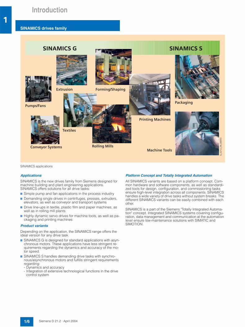
SINAMICS applications
Applications
SINAMICS is the new drives family from Siemens designed for machine building and plant engineering applications.SINAMICS offers solutions for all drive tasks:7 Simple pump and fan applications in the process industry7 Demanding single drives in centrifuges, presses, extruders,
elevators, as well as conveyor and transport systems7 Drive line-ups in textile, plastic film and paper machines, as
well as in rolling mill plants7 Highly dynamic servo drives for machine tools, as well as pa-
ckaging and printing machines
Product variants
Depending on the application, the SINAMICS range offers the ideal version for any drive task.7 SINAMICS G is designed for standard applications with asyn-
chronous motors. These applications have less stringent re-quirements regarding the dynamics and accuracy of the mo-tor speed.
7 SINAMICS S handles demanding drive tasks with synchro-nous/asynchronous motors and fulfills stringent requirements regarding:- Dynamics and accuracy- Integration of extensive technological functions in the drive
control system
Platform Concept and Totally Integrated Automation
All SINAMICS variants are based on a platform concept. Com-mon hardware and software components, as well as standardi-zed tools for design, configuration, and commissioning tasks ensure high-level integration across all components. SINAMICS handles a wide variety of drive tasks without system breaks. The different SINAMICS variants can be easily combined with each other.
SINAMICS is a part of the Siemens "Totally Integrated Automa-tion" concept. Integrated SINAMICS systems covering configu-ration, data management and communication at the automation level ensure low-maintenance solutions with SIMATIC andSIMOTION.
%&/
&%
#4
4
4
5
4
5
-.
.*
.
/0

Introduction
SINAMICS drives family
1/7Siemens D 21.2 · April 2004
1
SINAMICS as part of the Siemens modular automation system
Quality to DIN EN ISO 9001
SINAMICS is able to meet the highest requirements in terms of quality. Extensive quality assurance in product design as well as in all development and production processes ensures a con-stantly high level of quality.
Our quality assurance system has of course been certified by an independent body in accordance with DIN EN ISO 9001.
Suitable for use anywhere in the world
SINAMICS meets the requirements of relevant international stan-dards and regulations –a from the EN European standards through IEC to UL and cULus.

Introduction
SINAMICS S120 servo control drive system
1/8 Siemens D 21.2 · April 2004
1
SINAMICS S120 system overview
&
12
%
&%3*+%+%*+
0042142
5!
5
67
+2*(58!
+2*(58!
9
5 5
#
+2*(58! -
.
.*
.
//
&6%6(6*%
6%6(6*%
+2*(58
+2*(586%6(6*%
Introduction
SINAMICS S120 servo control drive system
1/9Siemens D 21.2 · April 2004
1
Modular system for demanding drive tasks
SINAMICS S120 solves demanding drive tasks for a wide range of industrial applications and is, therefore, designed as a modu-lar system. Users can choose from many different harmonized components and functions to create a solution that best meetstheir requirements. SIZER, a high-performance configuration tool, makes it easier to choose and determine the optimum drive configuration.
SINAMICS S120 is enhanced by a wide range of motors. Whe-ther synchronous or asynchronous, all motor types are suppor-ted by SINAMICS S120.
Drive for multi-axis applications
The trend towards separate axes in machine building is growing all the time. Where possible, central drives are being replacedby electronically coordinated servo drives. Drives with coupled DC links are required for this purpose, as they support economic energy exchange between braking and driving axes.SINAMICS S120 boasts line supplies and inverter modules co-vering a wide power range, which, having been designed for seamless integration, pave the way for compact multi-axis drive configurations.
New system architecture with a central control unit
Electronically coordinated individual drives work together to per-form your drive tasks. Higher-level controllers operate the drives to achieve the required coordinated movement. This requires cy-clic data exchange between the controller and all the drives.This exchange usually took place via a field bus, which required a great deal of time and effort for installation and configuration.SINAMICS S120 takes a different approach. A central control unit controls the drives for all connected axes and also estab-lishes the technological links between the drives and/or axes. Since all the required data is stored in the central control unit, itdoes not need to be transferred. Inter-axis connections can be established within a control unit and easily configured in the STARTER commissioning tool.
Simple technological tasks can be carried out automatically by the SINAMICS S120 control unit. For complex numerical or mo-tion-control tasks, high-performance SIMOTION D modules are used instead.
DRIVE-CLiQ – the digital interface between all components
All SINAMICS S120 components, including the motors and en-coders, are interconnected via a joint serial interface called DRIVE-CLiQ. The standardized cables and connectors reduce the variety of different parts and cut inventory costs.
Converter boards (sensor modules) for converting standard en-coder signals to DRIVE-CLiQ are available for third-party motors or retrofit applications.

Introduction
SINAMICS S120 servo control drive system
1/10 Siemens D 21.2 · April 2004
1
Electronic rating plate in all components
Detection of electronic rating plates via DRIVE-CLiQ with SINAMICS S120
All SINAMICS S120 components have an electronic rating plate that contains all the relevant data about that particular compo-nent. In the motors, for example, this data includes the parame-ters of the electric equivalent circuit diagram and characteristic values for the built-in motor encoder. The control unit records this data automatically via DRIVE-CLiQ so that it does not need to be entered during commissioning or when the equipment is re-placed.
In addition to the technical data, the rating plate includes logis-tical data (manufacturer ID, order number, and globally uniqueID). Since this data can be called up electronically on site or remotely, all the components used in a machine can alwaysbe individually identified, which helps simplify servicing.
&
12
%
&%3*+%+%*+
0042142
5!
5
67
+2*(58!
+2*(58!
9
5 5
#
+2*(58! -
.
.*
.
/:

Introduction
SINAMICS S120 servo control drive system
1/11Siemens D 21.2 · April 2004
1
SINAMICS S120 drive system components
#4+
4
5 5
*4 ,4
7 #
#4/4
67%
44 4 4
$# 4 6784
-.
.*
.
/;
#
#
55!5!5
94#4*
*) 4,4
Introduction
Notes
1/12 Siemens D 21.2 · April 2004
1
The overview on page 1/11 features the SINAMICS S120 com-ponents that are primarily used for multi-axis drive tasks.
The following power components are available:7 Line-side power components such as fuses, contactors, re-
actors, and filters for switching the power supply and meeting EMC requirements.
7 Line modules, which supply power centrally to the DC link.7 DC link components, which can be used as options to stabi-
lize the DC link voltage and/or to buffer the electronics power supply.
7 Motor modules, which act as inverters, receive power from the DC link, and buffer the connected motors.
The SINAMICS S120 components have been developed for in-stallation in cabinets. They have the following features and cha-racteristics:• Easy to handle, simple installation and wiring• Practical connection system, cable routing in accordance with
EMC requirements• Standardized design, seamless integration• Internal cooling-fans (other cooling methods available on re-
quest)
To carry out the required functions, SINAMICS S120 is equipped with:7 A control unit that carries out all drive and technological func-
tions across all axes.7 Additional system components that enhance functionality
and offer different interfaces for encoders and process sig-nals.

Siemens D 21.2 · April 2004
2/2 System data2/2 General technical data2/3 Overload capability2/4 Derating characteristics
2/5 Line-side power components
2/5 Line filters2/7 Line reactors2/9 Assignment overview
2/10 Line Modules2/10 Smart Line Modules2/13 Active Line Modules
2/16 Motor Modules2/16 Single Motor Modules2/21 Double Motor Modules
2/24 DC link components2/24 Braking Module2/26 Brake resistors2/27 Capacitor Module2/28 Control Supply Module2/29 DC link power supply adapter
2/30 Control units2/30 CU320 Control Unit2/33 CompactFlash Card
2/34 Supplementary system components
2/34 CBC10 Communication Board2/35 TB30 Terminal Board2/37 TM31 Terminal Module
2/39 Sensor system connection2/40 SMC10 Sensor Module Cabinet-
mounted2/41 SMC20 Sensor Module Cabinet-
mounted2/42 SMC30 Sensor Module Cabinet-
mounted
SINAMICS S120 Servo

SINAMICS S120 ServoSystem data
General technical data
2/2 Siemens D 21.2 · April 2004
2
Technical data
Unless explicitly specified otherwise, the following technical data are valid for all components of the SINAMICS S120 drive system described here.
Electrical data
Line connection voltage 3 AC 380 V to 480 V ±10%(-15% < 1 min)
Line frequency 50/60 Hz, -6/+6%
Electronic power supply DC 24 V, -15/+20%
Radio interference suppression
•Standard No radio interference suppression
•With line filter Class A1 to EN 55 011 possible
Overvoltage category Class III to EN 60 664-1
Mechanical data
Vibration stressing
•Transport EN 60 721-3-2, Class 2M3
•Operation EN 60 721-3-3, Class 3M4
Shock stressing
•Transport EN 60 721-3-2, Class 2M3
•Operation EN 60 721-3-3, Class 3M4
Ambient conditions
Degree of protection IP20 to EN 60 529
Protection class Class I (with protective conductor system) and Class III (PELV) to EN 61 800-5-1
Cooling method Internal ventilation, power sections with forced air cooling with inte-grated cooling fan
Ambient conditions
Permissible ambient and coolant temperature (air) during operation for line-side components, Line Modules and Motor Modules
0 °C (+32 °F) to +40 °C (+104 °F) without derating,> +40 °C (+104 °F) to +55 °C (+131 °F) see derating character-istics
Permissible ambient and coolant temperature (air) during operation for control units, additional system components, DC link components and Sensor Modules
0 °C (+32 °F) to +55 °C (+131 °F)
Climatic ambient conditions
•Storage Class 1K3 to EN 60 721-3-1Temperature -25 °C (-13 °F) to +55 °C (+131 °F)
•Transport Class 2K4 to EN 60 721-3-2Temperature -40 °C (-40 °F) to +70 °C (+158 °F)Max. humidity 95% at +40 °C (+104 °F)
•Operation Class 3K3 to EN 60 721-3-3Relative humidity 5 to 65% annual average,≤ 80% max. 2 months per year,condensation, splashwater and ice formation not permitted (EN 60 204, Part 1)
Environmental class/harmful chemical substances
•Storage Class 1C2 to EN 60 721-3-1
•Transport Class 2C2 to EN 60 721-3-2
•Operation Class 3C2 to EN 60 721-3-3
Organic/biological influences
•Storage Class 1B1 to EN 60 721-3-1
•Transport Class 2B1 to EN 60 721-3-2
•Operation Class 3B1 to EN 60 721-3-3
Degree of pollution 2 to EN 60 664-1
Installation altitude Up to 1000 m (3282 ft) above sea levelno derating,> 1000 m (3282 ft) to 5000 m (16,408 ft) above sea level see derating characteristics
Approvals
Certification CE (low-voltage and EMC Direc-tives), cULus (file nos.: E192450, E164110 and E70122)
Safety Integrated – safe standstill (SH) and safe brake control (SBC)
Safety Integrity Level (SIL) 2 to IEC 61508, control category 3 to EN 954-1
Modules
Line Modules in Booksize format
•Rated supply voltage 3 AC 380 V to 480 V
Active Line Modules in Booksize format
•Rated pulse frequency 8 kHz
Motor Modules in Booksize format
•DC link connection voltage DC 510 V to 750 V
•Rated pulse frequency 4 kHz
SINAMICS S120 ServoSystem data
General technical data
2/3Siemens D 21.2 · April 2004
2
Technical data (continued)
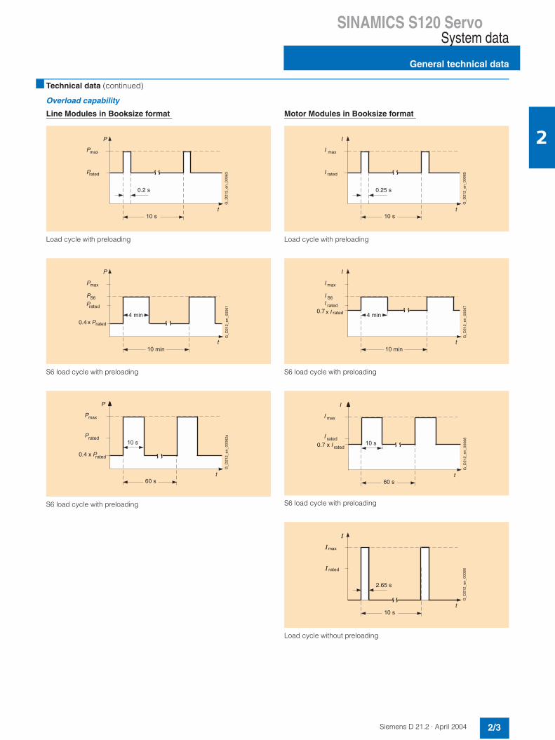
Overload capability
Line Modules in Booksize format
Load cycle with preloading
S6 load cycle with preloading
S6 load cycle with preloading
Motor Modules in Booksize format
Load cycle with preloading
S6 load cycle with preloading
S6 load cycle with preloading
Load cycle without preloading
10 s
t
P
P
P
max
0.2 s
G_D
212_
en_0
0063rated
10 min
t
4 min
P
P
P
max
S6
0.4
G_D
212_
en_0
0061
rated
Prated
x P
t
P
60 s
10 s
Pmax
0.4 x P
G_D
212_
en_0
0062
a
rated
Prated
10 s
t
I
I
I
max
0.25 s
G_D
212_
en_0
0065rated
10 min
t
4 min
I
I
I
max
S6
0.7
G_D
212_
en_0
0067
rated
I rated
x I
t
I
60 s
10 s
I max
0.7 x I
G_D
212_
en_0
0068
rated
Irated
10 s
t
max
G_D
212_
en_0
0066
2.65 s
rated

SINAMICS S120 ServoSystem data
Derating characteristics
2/4 Siemens D 21.2 · April 2004
2
Characteristics
Derating characteristics for Line Modules in Booksize format
Rated output power as a function of ambient temperature
Rated output power as a function of pulse frequency (Active Line Modules only)
Rated output power as a function of installation altitude
Correction factors for increased ambient temperatures and installation altitudes
If the Line and Motor Modules are operated at ambient temper-atures of > 40°C (104°F) and installation altitudes of > 1000 m (3282 ft), both derating characteristics must be taken into ac-count for the permissible output power/output current.
Derating characteristics for Motor Modules in Booksizeformat
Rated output current as a function of ambient temperature
Rated output current as a function of pulse frequency
Rated output current as a function of installation altitude
Example:
A motor module is to operate at an ambient temperature of 55°C (131°F) (60% permissible output current) and an installationaltitude of 3000 m (9845 ft) (75% permissible output current). The permissible output current in this case is 100 x (0.60 x 0.75) = 45%.
! "# !$# !%# !&# !# !&#
$
'
"
& & % %
!"
#$#"
%"&
&&'(
$&&
(&)&*&+&'&
& , ) $# $+ #&
,&-&
#&$&
# + $& $,
./0
11121313
!"
#$#"
%"&
&&+&
-#)# +'+- (),' $-$#+ $+,&)
$&&
('(&
)')&*'
& $&&& #&&& -&&& ,&&& '&&&
*&
+'+&
''
(
! "# !$# !%# !&# !# !&#
$
'
"
& & % %
!"
#$#"
%"&
&&&#
1$&&
(&)&*&+&'&
& , ) $# $+ #&
,&-&
#&$&
# + $& $,
./0
11121313
!"
#$#"
%"&
&&&-
1
-#)# +'+- (),' $-$#+ $+,&)
$&&
('(&
)')&*'
& $&&& #&&& -&&& ,&&& '&&&
*&
+'+&
''
SINAMICS S120 ServoLine-side power components
Line filters
2/5Siemens D 21.2 · April 2004
2
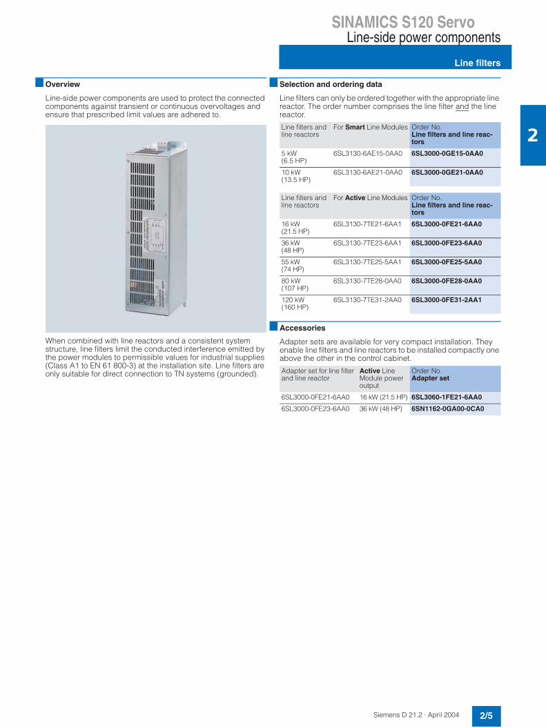
Overview
Line-side power components are used to protect the connected components against transient or continuous overvoltages andensure that prescribed limit values are adhered to.
When combined with line reactors and a consistent system structure, line filters limit the conducted interference emitted by the power modules to permissible values for industrial supplies (Class A1 to EN 61 800-3) at the installation site. Line filters are only suitable for direct connection to TN systems (grounded).
Selection and ordering data
Line filters can only be ordered together with the appropriate line reactor. The order number comprises the line filter and the line reactor.
Accessories
Adapter sets are available for very compact installation. They enable line filters and line reactors to be installed compactly one above the other in the control cabinet.
Line filters and line reactors
For Smart Line Modules Order No.Line filters and line reac-tors
5 kW (6.5 HP)
6SL3130-6AE15-0AA0 6SL3000-0GE15-0AA0
10 kW(13.5 HP)
6SL3130-6AE21-0AA0 6SL3000-0GE21-0AA0
Line filters and line reactors
For Active Line Modules Order No.Line filters and line reac-tors
16 kW (21.5 HP)
6SL3130-7TE21-6AA1 6SL3000-0FE21-6AA0
36 kW (48 HP)
6SL3130-7TE23-6AA1 6SL3000-0FE23-6AA0
55 kW (74 HP)
6SL3130-7TE25-5AA1 6SL3000-0FE25-5AA0
80 kW(107 HP)
6SL3130-7TE28-0AA0 6SL3000-0FE28-0AA0
120 kW(160 HP)
6SL3130-7TE31-2AA0 6SL3000-0FE31-2AA1
Adapter set for line filter and line reactor
Active Line Module power output
Order No.Adapter set
6SL3000-0FE21-6AA0 16 kW (21.5 HP) 6SL3060-1FE21-6AA0
6SL3000-0FE23-6AA0 36 kW (48 HP) 6SN1162-0GA00-0CA0
SINAMICS S120 ServoLine-side power components
Line filters
2/6 Siemens D 21.2 · April 2004
2
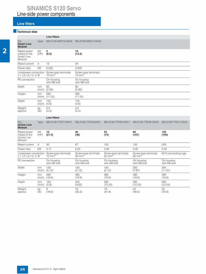
Technical data
Line filters
ForSmart Line Module
Type 6SL3130-6AE15-0AA0 6SL3130-6AE21-0AA0
Rated power infeed of the Smart LineModule
kW(HP)
5(6.5)
10(13.5)
Rated current A 12 24
Power loss kW 0.005 0.009
Line/power connection L1, L2, L3 / U, V, W
Screw-type terminals 10 mm2
Screw-type terminals 10 mm2
PE connection On housing with M6 bolt
On housing with M6 bolt
Width mm (inch)
60(2.36)
60(2.36)
Height mm (inch)
285(11.22)
285(11.22)
Depth mm (inch)
122(4.8)
122(4.8)
Weight, approx.
kg(lb)
2.0(4.4)
2.4(5.3)
Line filters
ForActive Line Module
Type 6SL3130-7TE21-6AA1 6SL3130-7TE23-6AA1 6SL3130-7TE25-5AA1 6SL3130-7TE28-0AA0 6SL3130-7TE31-2AA0
Rated power infeed of the Active LineModule
kW(HP)
16(21.5)
36(48)
55(74)
80(107)
120(160)
Rated current A 30 67 103 150 225
Power loss kW 0.17 0.25 0.35 0.45 0.59
Line/power connection L1, L2, L3 / U, V, W
Screw-type terminals 10 mm2
Screw-type terminals 50 mm2
Screw-type terminals50 mm2
Screw-type terminals 95 mm2
M10 connecting lugs
PE connection On housing with M5 bolt
On housing with M8 bolt
On housing with M8 bolt
On housing with M8 bolt
On housing with M8 bolt
Width mm (inch)
130(5.12)
130(5.12)
130(5.12)
200(7.87)
300(11.81)
Height mm (inch)
480(18.9)
480(18.9)
480(18.9)
480(18.9)
480(18.9)
Depth mm (inch)
150(5.9)
245(9.65)
260(10.24)
260(10.24)
260(10.24)
Weight, approx.
kg(lb)
9(19.8)
16(35.3)
19(41.9)
22(48.5)
32(70.6)
SINAMICS S120 ServoLine-side power components
Line reactors
2/7Siemens D 21.2 · April 2004
2
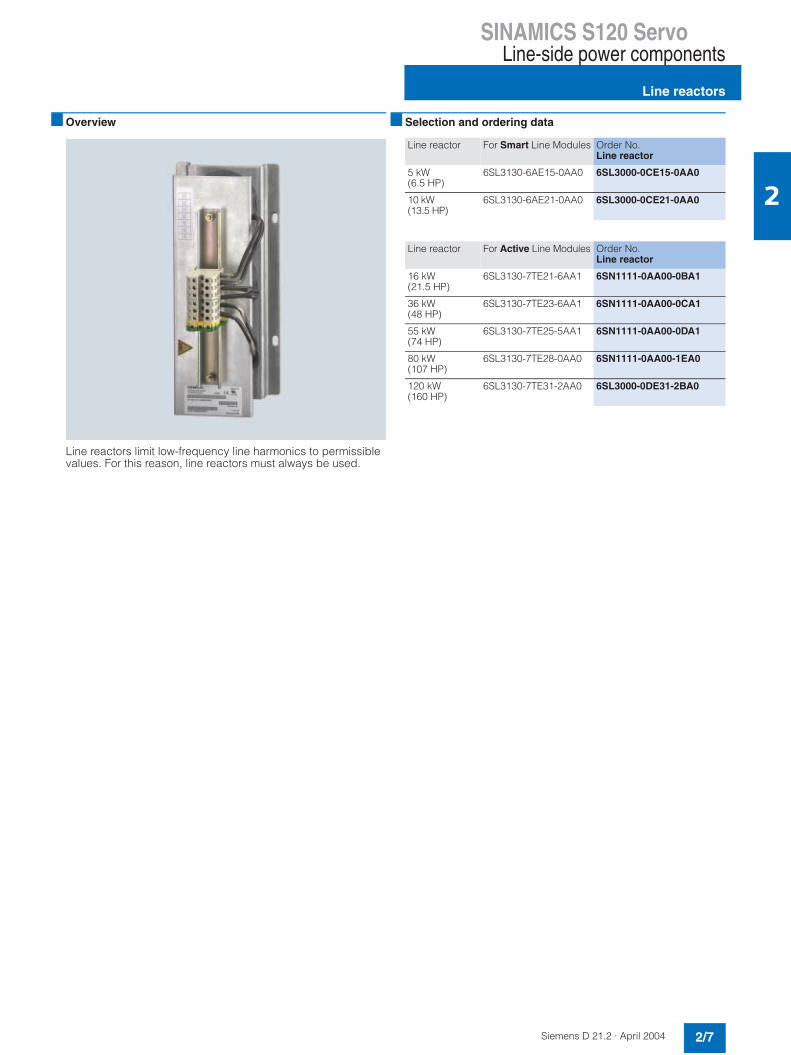
Overview
Line reactors limit low-frequency line harmonics to permissible values. For this reason, line reactors must always be used.
Selection and ordering data
Line reactor For Smart Line Modules Order No.Line reactor
5 kW (6.5 HP)
6SL3130-6AE15-0AA0 6SL3000-0CE15-0AA0
10 kW (13.5 HP)
6SL3130-6AE21-0AA0 6SL3000-0CE21-0AA0
Line reactor For Active Line Modules Order No.Line reactor
16 kW(21.5 HP)
6SL3130-7TE21-6AA1 6SN1111-0AA00-0BA1
36 kW(48 HP)
6SL3130-7TE23-6AA1 6SN1111-0AA00-0CA1
55 kW(74 HP)
6SL3130-7TE25-5AA1 6SN1111-0AA00-0DA1
80 kW(107 HP)
6SL3130-7TE28-0AA0 6SN1111-0AA00-1EA0
120 kW(160 HP)
6SL3130-7TE31-2AA0 6SL3000-0DE31-2BA0
SINAMICS S120 ServoLine-side power components
Line reactors
2/8 Siemens D 21.2 · April 2004
2
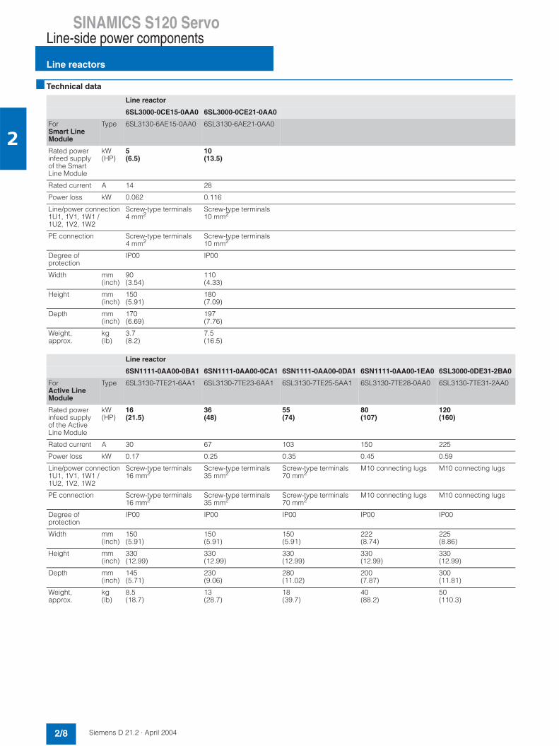
Technical data
Line reactor
6SL3000-0CE15-0AA0 6SL3000-0CE21-0AA0
ForSmart Line Module
Type 6SL3130-6AE15-0AA0 6SL3130-6AE21-0AA0
Rated power infeed supply of the Smart Line Module
kW(HP)
5(6.5)
10(13.5)
Rated current A 14 28
Power loss kW 0.062 0.116
Line/power connection 1U1, 1V1, 1W1 /1U2, 1V2, 1W2
Screw-type terminals 4 mm2
Screw-type terminals 10 mm2
PE connection Screw-type terminals4 mm2
Screw-type terminals 10 mm2
Degree ofprotection
IP00 IP00
Width mm (inch)
90(3.54)
110(4.33)
Height mm (inch)
150(5.91)
180(7.09)
Depth mm (inch)
170(6.69)
197(7.76)
Weight, approx.
kg(lb)
3.7(8.2)
7.5(16.5)
Line reactor
6SN1111-0AA00-0BA1 6SN1111-0AA00-0CA1 6SN1111-0AA00-0DA1 6SN1111-0AA00-1EA0 6SL3000-0DE31-2BA0
ForActive Line Module
Type 6SL3130-7TE21-6AA1 6SL3130-7TE23-6AA1 6SL3130-7TE25-5AA1 6SL3130-7TE28-0AA0 6SL3130-7TE31-2AA0
Rated power infeed supply of the ActiveLine Module
kW(HP)
16(21.5)
36(48)
55(74)
80(107)
120(160)
Rated current A 30 67 103 150 225
Power loss kW 0.17 0.25 0.35 0.45 0.59
Line/power connection1U1, 1V1, 1W1 /1U2, 1V2, 1W2
Screw-type terminals 16 mm2
Screw-type terminals 35 mm2
Screw-type terminals70 mm2
M10 connecting lugs M10 connecting lugs
PE connection Screw-type terminals16 mm2
Screw-type terminals 35 mm2
Screw-type terminals70 mm2
M10 connecting lugs M10 connecting lugs
Degree ofprotection
IP00 IP00 IP00 IP00 IP00
Width mm (inch)
150(5.91)
150(5.91)
150(5.91)
222(8.74)
225(8.86)
Height mm (inch)
330(12.99)
330(12.99)
330(12.99)
330(12.99)
330(12.99)
Depth mm (inch)
145(5.71)
230(9.06)
280(11.02)
200(7.87)
300(11.81)
Weight, approx.
kg(lb)
8.5(18.7)
13(28.7)
18(39.7)
40(88.2)
50(110.3)
SINAMICS S120 ServoLine-side power components
Assignment overview
2/9Siemens D 21.2 · April 2004
2
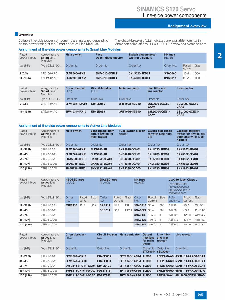
Overview
Suitable line-side power components are assigned depending on the power rating of the Smart or Active Line Modules.
The circuit-breakers (UL) indicated are available from North American sales offices: 1-800-964-4114 www.sea.siemens.com
Assignment of line-side power components to Smart Line Modules
Assignment of line-side power components to Active Line Modules
Ratedpower infeed
Assignment to Smart Line Modules
Main switch Fuseswitch disconnector
Switch disconnector with fuse holders
NH fuse (gL/gG)
kW (HP) Type 6SL3130-... Order No. Order No. Order No. Order No. Ratedcurrent
Size
5 (6.5) 6AE15-0AA0 3LD2003-0TK51 3NP4010-0CH01 3KL5030-1EB01 3NA3805 16 A 000
10 (13.5) 6AE21-0AA0 3LD2203-0TK51 3NP4010-0CH01 3KL5030-1EB01 3NA3814 35 A 000
Ratedpower infeed
Assignment to Smart Line Modules
Circuit-breaker (IEC)
Circuit-breaker (UL)
Main contactor Line filter and line reactor
Line reactor
kW (HP) Type 6SL3130-... Order No. Order No. Order No. Order No. Order No.
5 (6.5) 6AE15-0AA0 3RV1031-4BA10 ED43B015 3RT1023-1BB40 6SL3000-0GE15-0AA0
6SL3000-0CE15-0AA0
10 (13.5) 6AE21-0AA0 3RV1031-4FA10 ED43B035 3RT1026-1BB40 6SL3000-0GE21-0AA0
6SL3000-0CE21-0AA0
Ratedpower infeed
Assignment to Active Line Modules
Main switch Leading auxiliary circuit switch for main switch
Fuse switch discon-nector
Switch disconnec-tor with fuse hold-ers
Leading auxiliary switch for switch dis-connector with fuse holders
kW (HP) Type 6SL3130-... Order No. Order No. Order No. Order No. Order No.
16 (21.5) 7TE21-6AA1 3LD2504-0TK51 3LD9250-3B 3NP4010-0CH01 3KL5030-1EB01 3KX3552-3EA01
36 (48) 7TE23-6AA1 3LD2704-0TK51 3LD9250-3B 3NP4010-0CH01 3KL5230-1EB01 3KX3552-3EA01
55 (74) 7TE25-5AA1 3KA5330-1EE01 3KX3552-3EA01 3NP4270-0CA01 3KL5530-1EB01 3KX3552-3EA01
80 (107) 7TE28-0AA0 3KA5330-1EE01 3KX3552-3EA01 3NP4270-0CA01 3KL5530-1EB01 3KX3552-3EA01
120 (160) 7TE31-2AA0 3KA5730-1EE01 3KX3552-3EA01 3NP5360-0CA00 3KL5730-1EB01 3KX3552-3EA01
Ratedpower infeed
Assignment to Active Line Modules
NEOZED fuse (gL/gG)
DIAZED fuse (gL/gG)
NH fuse (gL/gG)
UL/CSA fuse, Class J Available from: Ferraz Shawmuthttp://www.ferraz-shawmut.com
kW (HP) Type 6SL3130-... Order No.
Ratedcurrent
Size Order No.
Ratedcurrent
Size Order No.
Ratedcurrent
Size Refer-ence No.
Ratedcurrent
Size
16 (21.5) 7TE21-6AA1 5SE2335 35 A D02 5SB411 35 A DIII 3NA3814 35 A 000 AJT35 35 A 27×60
36 (48) 7TE23-6AA1 5SC211 80 A DIVH 3NA3824 80 A 000 AJT80 80 A 29×117
55 (74) 7TE25-5AA1 3NA3132 125 A 1 AJT125 125 A 41×146
80 (107) 7TE28-0AA0 3NA3136 160 A 1 AJT175 175 A 41×146
120 (160) 7TE31-2AA0 3NA3144 250 A 1 AJT250 250 A 54×181
Ratedpower infeed
Assignment to Active Line Modules
Circuit-breaker(IEC)
Circuit-breaker(UL)
Main contactor Outputinterfacefor main switch
Line filter and line reactor
Line reactor
kW (HP) Type 6SL3130-... Order No. Order No. Order No. Order No.3TX7004-
Order No.6SL3000-
Order No.
16 (21.5) 7TE21-6AA1 3RV1031-4FA10 ED43B035 3RT1035-1AC24 1LB00 0FE21-6AA0 6SN1111-0AA00-0BA1
36 (48) 7TE23-6AA1 3RV1041-4LA10 ED43B080 3RT1045-1AP04 1LB00 0FE23-6AA0 6SN1111-0AA00-0CA1
55 (74) 7TE25-5AA1 3VF3211-3FU41-0AA0 ED43B125 3RT1054-1AP36 1LB00 0FE25-5AA0 6SN1111-0AA00-0DA1
80 (107) 7TE28-0AA0 3VF3211-3FW41-0AA0 FD63T175 3RT1056-6AP36 1LB00 0FE28-0AA0 6SN1111-0AA00-1EA0
120 (160) 7TE31-2AA0 3VF4211-3DM41-0AA0 FD63T250 3RT1065-6AP36 1LB00 0FE31-2AA1 6SL3000-0DE31-2BA0

SINAMICS S120 ServoLine Modules
Line Modules
2/10 Siemens D 21.2 · April 2004
2
Overview
The drives group is connected to the power supply network by means of a line module. The Smart Line Module and the Active Line Modules supply power to the DC link.
The line modules are suitable for direct operation on TN, TT (grounded) and IT (ungrounded) systems.
When the Smart and Active Line Modules are in regenerative feedback mode, the power supplied to the DC link from thedrives is fed back into the line. On a line which does not supportregenerative feedback the regenerative feedback function of the line module must be deactivated.
Overview
Smart Line Modules are non-regulated rectifier/regenerative units (diode bridge for incoming supply; stable, line-commu-tated feedback via IGBTs) with 100% regenerative feedback power. The regenerative feedback capability of the modules can be deactivated by means of a digital input.
Design
Smart Line Modules feature the following interfaces as standard:• 1 x line connection via plug-in screw-type terminal with inte-
grated shield connection plate• 1 x connection for the electronics power supply via the 24 V
terminal adapter included in the scope of supply• 2 x DC link connections via integrated DC link busbars• 2 x digital inputs• 1 x digital output• 2 x PE (protective earth) connections
The status of the Smart Line Modules is indicated via two multi-color LEDs.
The signal line shield can be connected to the line module via a shield connection terminal, e.g. Weidmüller type KLBÜ 3-8 SC. The shield connection terminal must not be used for strain relief.
Selection and ordering data
Accessories
Smart Line Modules
Smart Line Module Order No.
5 kW (6.5 HP) 6SL3130-6AE15-0AA0
10 kW (13.5 HP) 6SL3130-6AE21-0AA0
Description Order No.
Warning labels in foreign lan-guagesThis set of foreign language warn-ing labels can be placed over thestandard German or English signs.One label in each of the followinglanguages is provided in each set:Chinese, Danish, Dutch, Finnish, French, Greek, Italian, Japanese, Korean, Portuguese, Spanish and Swedish.
6SL3166-3AB00-0AA0
SINAMICS S120 ServoLine Modules
Smart Line Modules
2/11Siemens D 21.2 · April 2004
2
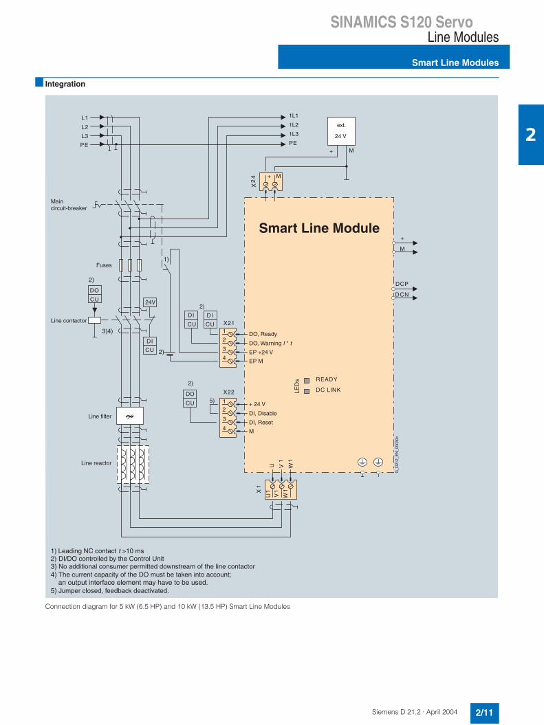
Integration
Connection diagram for 5 kW (6.5 HP) and 10 kW (13.5 HP) Smart Line Modules
M
+
DCN
DCP
READY
DC LINKLED
s
L3
L2
L1
PE
1L3
1L2
1L1
PE
X21
4
2
3
1
U
X1
V1
W1
V1
W1
U1
X22
4
2
3
1
DO
CU
D I
CU
DI
C
24V
U
DI
CU
DO
CU
1)
3)4)
2)
2)
5)
2)
2)
X2
4 + M
+ M
Smart Line Module
EP M
EP +24 V
DO, Warning I * t
DO, Ready
M
DI, Reset
DI, Disable
+ 24 V
1) Leading NC contact t >10 ms2) DI/DO controlled by the Control Unit
No additional consumer permitted downstream of the line contactor The current capacity of the DO must be taken into account;
Jumper closed, feedback deactivated.
3)
5)
4) an output interface element may have to be used.
Line reactor
Line filter
Line contactor
Fuses
Maincircuit-breaker
ext.
24 V
G_D
212_
EN
_000
30c

SINAMICS S120 ServoLine Modules
Smart Line Modules
2/12 Siemens D 21.2 · April 2004
2
Technical data
Smart Line Module 6SL3130-6AE15-0AA0 6SL3130-6AE21-0AA0
Rated infeed/regenerative power Prated kW(HP)
5(6.5)
10(13.5)
Infeed/regenerative power for S6 duty (40%) PS6 kW(HP)
6.5(8.5)
13(17.5)
Max. infeed/regenerative power Pmax kW(HP)
10(13.5)
20(27)
Rated DC link infeed current A 8.3 16.6
DC link infeed current for S6 duty (40%) A 11 22
Max. DC link infeed current A 16.6 33.2
Rated input current A 12 24
Input current for S6 duty (40%) A on request on request
Max. input current A on request on request
Max. current requirements (at 24 V DC) A 1.0 1.3
24 V DC busbar current capacity A 20 20
DC link capacitance µF 220 330
Max. DC link capacitance of drive group µF 6000 6000
DC link busbar current capacity A 100 100
Efficiency η 0.95 0.95
Power loss kW on request on request
Cooling air requirement m3/s(ft3/s)
0.008(0.283)
0.008(0.283)
Sound pressure level dB (A) < 60 < 60
Power connection U1, V1, W1 Screw-type terminals 2.5-6 mm2 (X1) Screw-type terminals 2.5-6 mm2 (X1)
PE connection On housing with M5 screw On housing with M5 screw
Max. cable length(total of all motor power cables andDC link)
m (ft) 350 (1150) (shielded)560 (1840) (unshielded)
350 (1150) (shielded)560 (1840) (unshielded)
Width mm (inch)
50(1.97)
50(1.97)
Height mm (inch)
380(14.96)
380(14.96)
Depth mm(inch)
270(10.63)
270(10.63)
Weight, approx. kg (lb)
4.7(10.4)
4.8 (10.6)

SINAMICS S120 ServoLine Modules
Active Line Modules
2/13Siemens D 21.2 · April 2004
2
Overview
The self-controlled rectifier/regenerative units (with IGBTs in in-feed and regenerative direction) with step-up converters gener-ate an increased, regulated DC link voltage, meaning that the connected motor modules are not dependent on line tolerances.
Design
Active Line Modules feature the following interfaces as standard:• 1 x power connection via screw terminals with integrated
shield connection plate (up to and including 16 kW (21.5 HP) rated power supply)
• 1 x connection for the electronics power supply via the 24 V terminal adapter included in the scope of supply
• 1 x DC link connection via integrated DC link busbars• 3 x DRIVE-CLiQ sockets• 2 x PE (protective earth) connections
The status of the Active Line Modules is indicated via two multi-color LEDs.
The shield for the power supply cable can be connected to the integrated shield connection plate of the 100 mm (3.94 in) wide Active Line Module via connection plate via a shield connection terminal or hose-clamp, e.g. Weidmüller type KLBÜ CO 4. Theshield connection terminal must not be used for strain relief. Ashield connection plate can be supplied for 150 mm (5.91 in), 200 mm (7.87 in) and 300 mm (11.81 in) wide modules.
The signal line shield can be connected to the line module via a shield connection terminal, e.g. Weidmüller type KLBÜ 3-8 SC. The shield connection terminal must not be used for strain relief.
Selection and ordering data
Accessories
Active Line Module Order No.
16 kW (21.5 HP) 6SL3130-7TE21-6AA1
36 kW (48 HP) 6SL3130-7TE23-6AA1
55 kW (74 HP) 6SL3130-7TE25-5AA1
80 kW (107 HP) 6SL3130-7TE28-0AA0
120 kW (160 HP) 6SL3130-7TE31-2AA0
Description Order No.
Shield connection platefor 150 mm (5.91 in) Line/Motor Modules
6SL3162-1AF00-0AA0
Shield connection platefor 200 mm (7.87 in) Line/Motor Modules and 300 mm (11.81 in)
6SL3162-1AH00-0AA0
Warning labels in foreign lan-guagesThis set of foreign language warn-ing labels can be placed over thestandard German or English signs.One label in each of the followinglanguages is provided in each set:Chinese, Danish, Dutch, Finnish, French, Greek, Italian, Japanese, Korean, Portuguese, Spanish and Swedish.
6SL3166-3AB00-0AA0
SINAMICS S120 ServoLine Modules
Active Line Modules
2/14 Siemens D 21.2 · April 2004
2
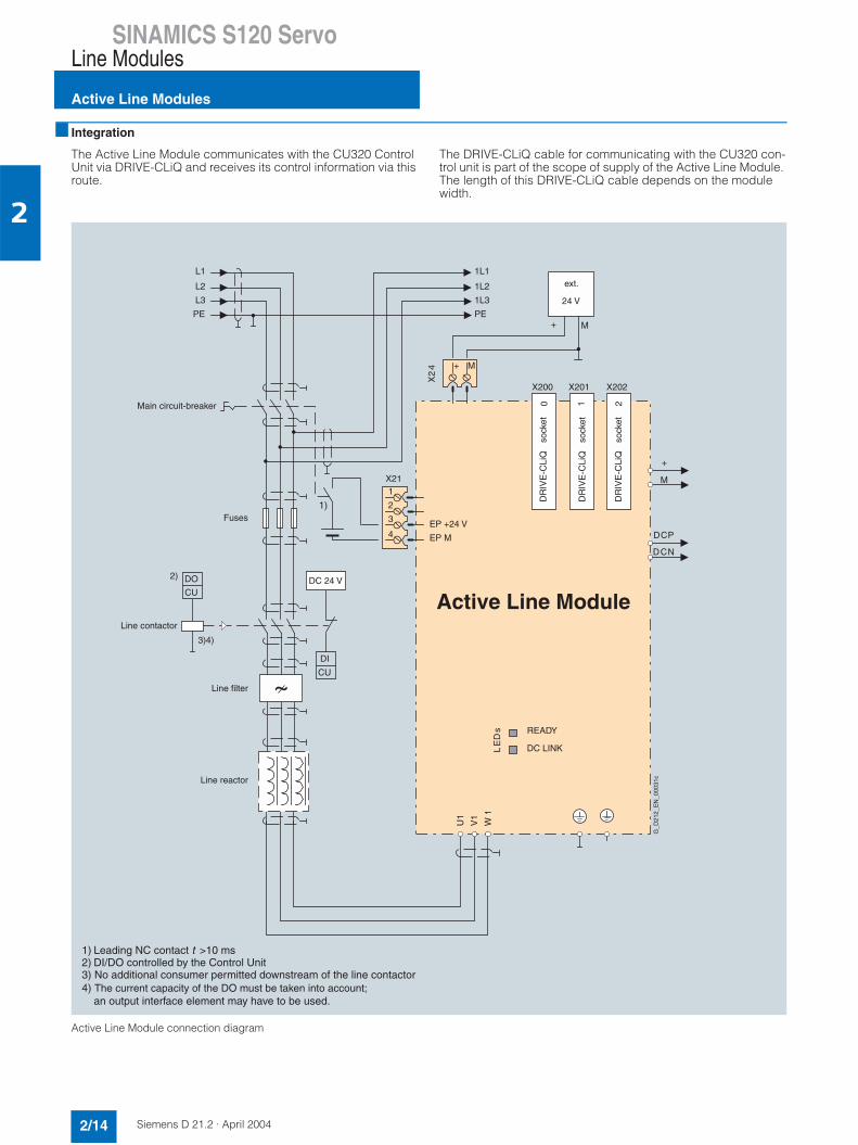
Integration
The Active Line Module communicates with the CU320 Control Unit via DRIVE-CLiQ and receives its control information via this route.
The DRIVE-CLiQ cable for communicating with the CU320 con-trol unit is part of the scope of supply of the Active Line Module.The length of this DRIVE-CLiQ cable depends on the module width.
Active Line Module connection diagram
X202
1
X201
READY
DC LINK LE
Ds
2D
RIV
E-C
LiQ
DR
IVE
-CLi
Q
DR
IVE
-CLi
Q0
X200
L3
L2
L1
PE
1L3
1L2
PE
1L1
1)
EP +24 V
X21
4
3
2
1
EP M
U1
V1
W 1
DO
CU
2)
+ M
+ M
X2
4
Active Line Module
3)4)
DI
CU
DC 24 V
M
+
DCN
DCP
1) Leading NC contactDI/DO controlled by the Control Unit
t >10 ms2)3) No additional consumer permitted downstream of the line contactor4) The current capacity of the DO must be taken into account; an output interface element may have to be used.
Main circuit-breaker
Fuses
Line contactor
G_D
212_
EN
_000
31c
Line filter
Line reactor
ext.
24 V
sock
et
sock
et
sock
et

SINAMICS S120 ServoLine Modules
Active Line Modules
2/15Siemens D 21.2 · April 2004
2
Technical data
Active Line Module 6SL3130-7TE21-6AA1 6SL3130-7TE23-6AA1 6SL3130-7TE25-5AA1 6SL3130-7TE28-0AA0 6SL3130-7TE31-2AA0
Ratedinfeed/regener-ative powerPrated
kW(HP)
16(21.5)
36(48)
55(74)
80(107)
120(160)
Infeed/regener-ative power forS6 duty (40%)PS6
kW(HP)
21(28)
47(63)
71(95)
106(142)
158(212)
Max. infeed/re-generativepower Pmax
kW(HP)
35(45)
70(94)
91(122)
131(176)
175(235)
Rated DC link infeed current
A 27 60 92 134 200
DC link infeed current for S6duty (40%)
A 35 79 121 176 244
Max. DC link infeed current
A 59 117 152 195 292
Rated input current
A 26 58 88 128 192
Input current for S6 duty(40%)
A 35 79 121 176 244
Max. input cur-rent
A 59 117 152 195 292
Max. currentrequirements (at 24 V DC)
A 1.1 1.5 1.9 2.0 2.5
24 V DC bus-bar current capacity
A 20 20 20 20 20
DC link capaci-tance
µF 710 1410 1880 2820 3760
Max. DC link capacitance of drive group
µF 20000 20000 20000 20000 20000
DC link busbar current capac-ity
A 100 100 200 200 200
Efficiency η 0.95 0.95 0.95 0.95 0.95
Power loss kW 0.26 0.63 0.90 1.35 2.20
Cooling air requirement
m3/s(ft3/s)
0.016(0.565)
0.031(1.095)
0.044(1.554)
0.144(5.085)
0.144(5.085)
Sound pres-sure level
dB < 60 < 65 < 60 < 75 < 75
Power connec-tionU1, V1, W1
Screw-type terminals2.5-10 mm2 (X1)
Screw studs for ring terminal ends, M6,2.5-50 mm2 (X1)
Screw studs for ring terminal ends, M8,2.5-95 mm2,2 x 35 mm2 (X1)
Screw studs for ring terminal ends, M8,2.5-120 mm2,2 x 50 mm2(X1)
Screw studs for ring terminal ends, M8,2.5-120 mm2,2 x 50 mm2(X1)
PE connection On housing with M5screw
On housing with M6 screw
On housing with M6 screw
On housing with M8 screw
On housing with M8 screw
Max. cable length (total of all motor power cables and DClink)
m (ft) 350 (1150) (shielded)560 (1840) (unshielded)
350 (1150) (shielded)560 (1840)(unshielded)
350 (1150) (shielded)560 (1840)(unshielded)
350 (1150) (shielded)560 (1840) (unshielded)
350 (1150) (shielded)560 (1840)(unshielded)
Width mm (inch)
100(3.94)
150(5.91)
200(7.87)
300(11.81)
300(11.81)
Height mm (inch)
380(14.96)
380(14.96)
380(14.96)
380(14.96)
380(14.96)
Depth mm (inch)
270(10.63)
270(10.63)
270(10.63)
270(10.63)
270(10.63)
Weight, approx.
kg (lb) 7 (15.4) 10.3 (22.7) 17 (37.5) 23 (50.7) 23 (50.7)

SINAMICS S120 ServoMotor Modules
Motor Modules
2/16 Siemens D 21.2 · April 2004
2
Overview
A wide range of single axis and double axis Motor Modules with various current/power ratings are available: • Single Motor Modules: Single axis module in booksize format
with rated output currents of 3 A to 200 A
• Double Motor Modules: Two-axis module in booksize format with rated output currents of 3 A to 18 A
In principle, all Single Motor and Double Motor Modules can be operated on Smart or Active Line Modules.
Design
Single Motor Modules feature the following interfaces as stan-dard:• 2 x DC link connections via integrated DC link busbars• 1 x electronics power supply connection via integrated 24 V
DC bars• 3 x DRIVE-CLiQ sockets• 1 x motor connection, plug-in (not included in scope of sup-
ply) or screw-stud depending on rated output current• 2 x safe standstill input terminals (enable pulses) • 1 x safe motor brake control• 1 x temperature sensor input (KTY84-130)• 2 x PE (protective earth) connections
The status of the Motor Modules is indicated via two multi-color LEDs.
The motor cable shield of the 50 mm (1.97 in) and 100 mm (3.94 in) modules is inside the connector. A shield connection plate can be supplied for the 150 mm (5.91 in), 200 mm (7.87 in) and 300 mm (11.81 in) wide modules. On these modules, the motor cable shield can be connected using a hose-clamp.
The signal line shield can be connected to the line module via a shield connection terminal, e.g. Weidmüller type KLBÜ 3-8 SC. The shield connection terminal must not be used for strain relief.
Selection and ordering data
Single Motor Modules
Single Motor ModuleRated output currentA
Rated powerkW (HP)
Order No.
3 1.6 (2) 6SL3120-1TE13-0AA0
5 2.7 (3.5) 6SL3120-1TE15-0AA0
9 4.8 (6.5) 6SL3120-1TE21-0AA1
18 9.7 (13) 6SL3120-1TE21-8AA1
30 16 (21.5) 6SL3120-1TE23-0AA1
45 24 (32) 6SL3120-1TE24-5AA1
60 32 (43) 6SL3120-1TE26-0AA1
85 46 (62) 6SL3120-1TE28-5AA1
132 71 (95) 6SL3120-1TE31-3AA0
200 107 (143) 6SL3120-1TE32-0AA0

SINAMICS S120 ServoMotor Modules
Single Motor Modules
2/17Siemens D 21.2 · April 2004
2
Accessories
Integration
The Single Motor Module communicates with the CU320 Control Unit via DRIVE-CLiQ and receives its control information via this route.
The required DRIVE-CLiQ cable for connecting to the next DRIVE-CLiQ device in the axis grouping is included in the scope of supply. The length of this DRIVE-CLiQ cable depends on the module width.
Wiring diagram for the 3 A to 30 A Single Motor Modules
Description Order No.
Shield connection platefor 150 mm (5.91 in) Line/Motor Modules
6SL3162-1AF00-0AA0
Shield connection platefor 200 mm (7.87 in) and 300 mm (11.81 in) Line/Motor Modules
6SL3162-1AH00-0AA0
DC link power supply adapterfor direct infeed of DC link voltageScrew-type terminals 0.5-10 mm2
for 50 mm (1.97 in) and 100 mm (3.94 in) Line/Motor Modules
6SL3162-2BD00-0AA0
DC link power supply adapterfor direct infeed of DC link voltageScrew-type terminals 35-95 mm2
for 150 mm (5.91 in), 200 mm (7.87 in) and 300 mm (11.81 in) Line/Motor Modules
6SL3162-2BM00-0AA0
Description Order No.
DC link adapters (2x)for multi-tier configurationScrew-type terminals 35-95 mm2
for all Line Modules/Motor Modules in book-size format
6SL3162-2BM01-0AA0
24 V terminal adapter 6SL3162-2AA00-0AA0
Warning labels in foreign languagesThis set of foreign language warning labelscan be placed over the standard German orEnglish signs.One label in each of the following languages is provided in each set:Chinese, Danish, Dutch, Finnish, French,Greek, Italian, Japanese, Korean, Portu-guese, Spanish and Swedish.
6SL3166-3AB00-0AA0
Plug-in motor brake connector for MotorModules with a rated output current ≥ 45 AWagohttp://www.wago.com
Item No.:231-102/037-000(Wago)
X201X200
READY
DC LINK LE
Ds
M
+
DCN
DCP
M
+
DCN
DCP
0 1
+Temp
X21
-Temp
EP M1
EP +24 V U2
V2
BR+
W2
BR-
X202
X1
4
3
2
1
1) ~M
3
E
Single Motor Module
DRIVE-CLiQ
DR
IVE
-CLi
Q
DR
IVE
-CLi
Q
G_D212_EN_00032c
DC link busbars
24 V DC busbars
socket 2
sock
et
sock
et
1) Required for Safety

SINAMICS S120 ServoMotor Modules
Single Motor Modules
2/18 Siemens D 21.2 · April 2004
2
Integration (continued)
Wiring diagram for the 45 A to 200 A Single Motor Modules
X201X200
READY
DC LINK LE
Ds
DR
IVE
-CLi
Q0
DR
IVE
-CLi
Q1
+Temp
X21
-Temp
EP M1
EP +24 V
BR+
BR-
X202
4
3
2
1
M3
E
U2
V2
X11
M
+
DCN
DCP
M
+
DCN
DCP
Single Motor Module
2)
1)
3)
+
X12
22
1
-
3) Also for 45 A to 132 A Single Motor Modules
1
2
W2
G_D212_EN_00033c
DC link busbars
24 V DC busbars
DRIVE-CLiQ socket 2
sock
et
sock
et
Fan
2) Also for 132 A to 200 A Single Motor Modules1) Required for Safety

SINAMICS S120 ServoMotor Modules
Single Motor Modules
2/19Siemens D 21.2 · April 2004
2
Technical data
Single Motor Module 6SL3120-1TE13-0AA0 6SL3120-1TE15-0AA0 6SL3120-1TE21-0AA1 6SL3120-1TE21-8AA1 6SL3120-1TE23-0AA1
Rated outputcurrent Irated
A 3 5 9 18 30
Output currentat S6 duty (40%) IS6
A 3.5 6 10 24 40
Max. output current Imax
A 6 10 18 36 56
Rated power at 600 V DC DC link voltage
kW(HP)
1.6(2)
2.7(3.5)
4.8(6.5)
9.7 (13)
16.0(21.5)
DC linkvoltage range
V 510 to 750 510 to 750 510 to 750 510 to 750 510 to 750
DC linkovervoltage trip
V 820 (± 2%) 820 (± 2%) 820 (± 2%) 820 (± 2%) 820 (± 2%)
DC link busbar current capac-ity
A 100 100 100 100 100
DC link capaci-tance
µF 110 110 110 220 710
Max. currentrequirement (at 24 V DC)
A 0.8 0.8 0.85 0.85 0.9
24 V DC bus-bar current capacity
A 20 20 20 20 20
If, due to a number of line and motor modules being mounted side-by-side, the current carrying capacity exceeds 20 A, an additional 24 V DC connection using a 24 V terminal adapter is required (max. cross-section 6 mm2, max. fuse protection20 A).
Efficiency η 0.97 0.97 0.97 0.97 0.97
Power loss kW 0.035 0.055 0.080 0.165 0.290
Cooling air requirement
m3/s(ft3/s)
0.008(0.283)
0.008(0.283)
0.008(0.283)
0.008(0.283)
0.016(0.565)
Sound pres-sure level
dB < 60 < 60 < 60 < 60 < 60
Motor connec-tionU2, V2, W2
Plug-in connector (X1),max. 30 A
Plug-in connector (X1),max. 30 A
Plug-in connector (X1),max. 30 A
Plug-in connector (X1),max. 30 A
Plug-in connector (X1),max. 30 A
PE connection On housing with M5screw
On housing with M5 screw
On housing with M5 screw
On housing with M5 screw
On housing with M5 screw
Motor brake connection
Integrated in the plug-in motor connector(X1),24 V DC, 2 A
Integrated in the plug-in motor connector (X1),24 V DC, 2 A
Integrated in the plug-in motor connector(X1),24 V DC, 2 A
Integrated in the plug-in motor connector(X1),24 V DC, 2 A
Integrated in the plug-in motor connector(X1),24 V DC, 2 A
Max. motor power cable length
m (ft) 50 (164) (shielded)75 (246) (unshielded)
50 (164) (shielded)75 (246) (unshielded)
50 (164) (shielded)75 (246) (unshielded)
50 (164) (shielded)75 (246) (unshielded)
50 (164) (shielded)75 (246) (unshielded)
Width mm (inch)
50(1.97)
50(1.97)
50(1.97)
50(1.97)
100(3.94)
Height mm (inch)
380(14.96)
380(14.96)
380(14.96)
380(14.96)
380(14.96)
Depth mm (inch)
270(10.63)
270(10.63)
270(10.63)
270(10.63)
270(10.63)
Weight, approx.
kg(lb)
5.1(11.2)
5.1(11.2)
5(11)
5(11)
6.9(15.2)
SINAMICS S120 ServoMotor Modules
Single Motor Modules
2/20 Siemens D 21.2 · April 2004
2
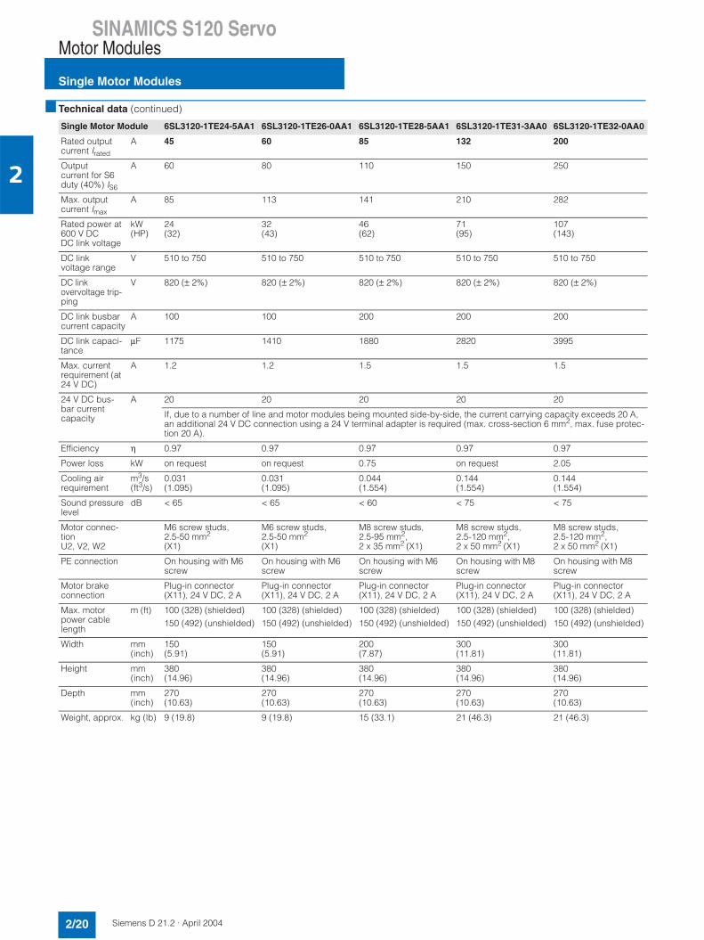
Technical data (continued)
Single Motor Module 6SL3120-1TE24-5AA1 6SL3120-1TE26-0AA1 6SL3120-1TE28-5AA1 6SL3120-1TE31-3AA0 6SL3120-1TE32-0AA0
Rated outputcurrent Irated
A 45 60 85 132 200
Outputcurrent for S6duty (40%) IS6
A 60 80 110 150 250
Max. outputcurrent Imax
A 85 113 141 210 282
Rated power at600 V DC DC link voltage
kW(HP)
24(32)
32(43)
46(62)
71(95)
107(143)
DC linkvoltage range
V 510 to 750 510 to 750 510 to 750 510 to 750 510 to 750
DC link overvoltage trip-ping
V 820 (± 2%) 820 (± 2%) 820 (± 2%) 820 (± 2%) 820 (± 2%)
DC link busbar current capacity
A 100 100 200 200 200
DC link capaci-tance
µF 1175 1410 1880 2820 3995
Max. currentrequirement (at 24 V DC)
A 1.2 1.2 1.5 1.5 1.5
24 V DC bus-bar current capacity
A 20 20 20 20 20
If, due to a number of line and motor modules being mounted side-by-side, the current carrying capacity exceeds 20 A,an additional 24 V DC connection using a 24 V terminal adapter is required (max. cross-section 6 mm2, max. fuse protec-tion 20 A).
Efficiency η 0.97 0.97 0.97 0.97 0.97
Power loss kW on request on request 0.75 on request 2.05
Cooling air requirement
m3/s(ft3/s)
0.031(1.095)
0.031(1.095)
0.044(1.554)
0.144(1.554)
0.144(1.554)
Sound pressure level
dB < 65 < 65 < 60 < 75 < 75
Motor connec-tionU2, V2, W2
M6 screw studs, 2.5-50 mm2
(X1)
M6 screw studs, 2.5-50 mm2
(X1)
M8 screw studs,2.5-95 mm2,2 x 35 mm2 (X1)
M8 screw studs,2.5-120 mm2,2 x 50 mm2 (X1)
M8 screw studs,2.5-120 mm2,2 x 50 mm2 (X1)
PE connection On housing with M6screw
On housing with M6 screw
On housing with M6 screw
On housing with M8 screw
On housing with M8 screw
Motor brake connection
Plug-in connector (X11), 24 V DC, 2 A
Plug-in connector (X11), 24 V DC, 2 A
Plug-in connector (X11), 24 V DC, 2 A
Plug-in connector (X11), 24 V DC, 2 A
Plug-in connector (X11), 24 V DC, 2 A
Max. motor power cable length
m (ft) 100 (328) (shielded)150 (492) (unshielded)
100 (328) (shielded)150 (492) (unshielded)
100 (328) (shielded)150 (492) (unshielded)
100 (328) (shielded)150 (492) (unshielded)
100 (328) (shielded)150 (492) (unshielded)
Width mm (inch)
150(5.91)
150(5.91)
200(7.87)
300(11.81)
300(11.81)
Height mm (inch)
380(14.96)
380(14.96)
380(14.96)
380(14.96)
380(14.96)
Depth mm (inch)
270(10.63)
270(10.63)
270(10.63)
270(10.63)
270(10.63)
Weight, approx. kg (lb) 9 (19.8) 9 (19.8) 15 (33.1) 21 (46.3) 21 (46.3)
SINAMICS S120 ServoMotor Modules
Double Motor Modules
2/21Siemens D 21.2 · April 2004
2
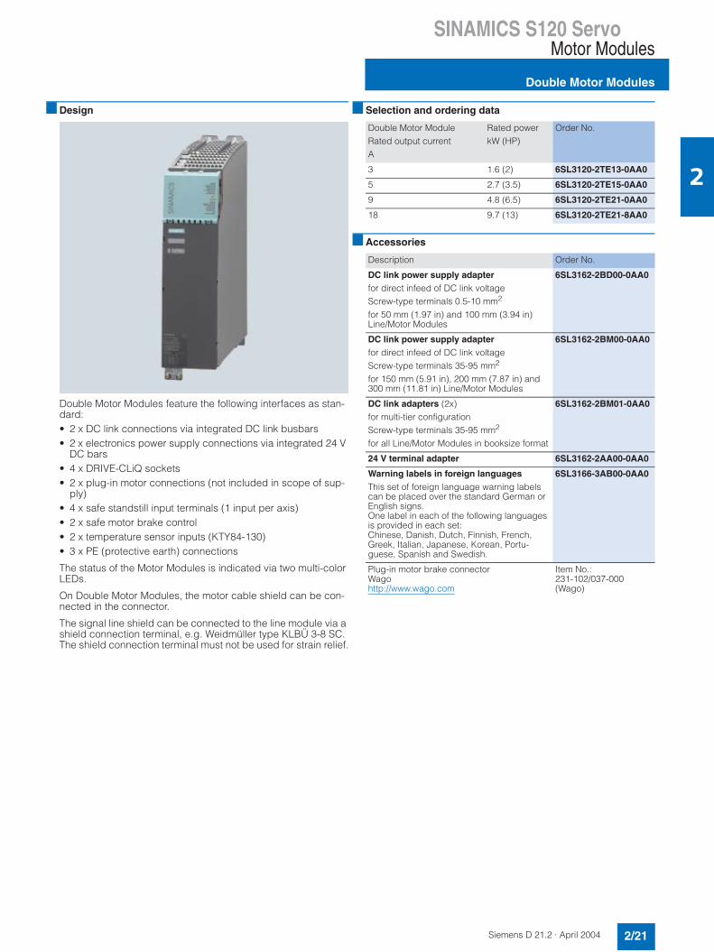
Design
Double Motor Modules feature the following interfaces as stan-dard:• 2 x DC link connections via integrated DC link busbars• 2 x electronics power supply connections via integrated 24 V
DC bars• 4 x DRIVE-CLiQ sockets• 2 x plug-in motor connections (not included in scope of sup-
ply)• 4 x safe standstill input terminals (1 input per axis)• 2 x safe motor brake control• 2 x temperature sensor inputs (KTY84-130)• 3 x PE (protective earth) connections
The status of the Motor Modules is indicated via two multi-color LEDs.
On Double Motor Modules, the motor cable shield can be con-nected in the connector.
The signal line shield can be connected to the line module via a shield connection terminal, e.g. Weidmüller type KLBÜ 3-8 SC. The shield connection terminal must not be used for strain relief.
Selection and ordering data
Accessories
Double Motor ModuleRated output currentA
Rated powerkW (HP)
Order No.
3 1.6 (2) 6SL3120-2TE13-0AA0
5 2.7 (3.5) 6SL3120-2TE15-0AA0
9 4.8 (6.5) 6SL3120-2TE21-0AA0
18 9.7 (13) 6SL3120-2TE21-8AA0
Description Order No.
DC link power supply adapterfor direct infeed of DC link voltageScrew-type terminals 0.5-10 mm2
for 50 mm (1.97 in) and 100 mm (3.94 in) Line/Motor Modules
6SL3162-2BD00-0AA0
DC link power supply adapterfor direct infeed of DC link voltageScrew-type terminals 35-95 mm2
for 150 mm (5.91 in), 200 mm (7.87 in) and 300 mm (11.81 in) Line/Motor Modules
6SL3162-2BM00-0AA0
DC link adapters (2x)for multi-tier configurationScrew-type terminals 35-95 mm2
for all Line/Motor Modules in booksize format
6SL3162-2BM01-0AA0
24 V terminal adapter 6SL3162-2AA00-0AA0
Warning labels in foreign languagesThis set of foreign language warning labelscan be placed over the standard German orEnglish signs.One label in each of the following languages is provided in each set:Chinese, Danish, Dutch, Finnish, French,Greek, Italian, Japanese, Korean, Portu-guese, Spanish and Swedish.
6SL3166-3AB00-0AA0
Plug-in motor brake connectorWagohttp://www.wago.com
Item No.:231-102/037-000(Wago)

SINAMICS S120 ServoMotor Modules
Double Motor Modules
2/22 Siemens D 21.2 · April 2004
2
Integration
The Double Motor Module communicates with the CU320 Con-trol Unit via DRIVE-CLiQ and receives its control information via this route.
The required DRIVE-CLiQ cable for connecting to the next DRIVE-CLiQ device in the axis grouping is included in the scope of supply. The length of this DRIVE-CLiQ cable depends on the module width.
Wiring diagram for the 2x3 A to 2x18 A Double Motor Modules
X201X200
READY
DC LINK LE
Ds
DR
IVE
-CLi
Q0
DR
IVE
-CLi
Q1
+Temp
X21
-Temp
EP M1
EP +24 V
-
+
U2
V2
BR+
W2
BR-
X202
X1
-
+
U2
V2
BR+
W2
BR-
X203
~M
3
EX2
+Temp
X22
4
3
2
1
1)
1)
-Temp
EP M1
EP +24 V
4
3
2
1
~M
3
E
M
+
DCN
DCP
M
+
DCN
DCP
Double Motor Module
G_D212_EN_00034c
DRIVE-CLiQ socket 3
DRIVE-CLiQ socket 2
DC link busbars
sock
et
sock
et
24 V DC busbars
1) Required for Safety
SINAMICS S120 ServoMotor Modules
Double Motor Modules
2/23Siemens D 21.2 · April 2004
2
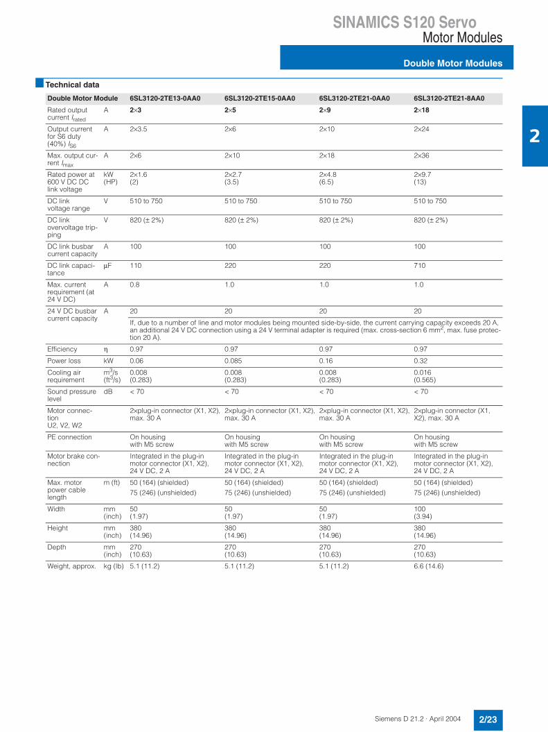
Technical data
Double Motor Module 6SL3120-2TE13-0AA0 6SL3120-2TE15-0AA0 6SL3120-2TE21-0AA0 6SL3120-2TE21-8AA0
Rated outputcurrent Irated
A 2×3 2×5 2×9 2×18
Output currentfor S6 duty(40%) IS6
A 2×3.5 2×6 2×10 2×24
Max. output cur-rent Imax
A 2×6 2×10 2×18 2×36
Rated power at600 V DC DClink voltage
kW(HP)
2×1.6(2)
2×2.7(3.5)
2×4.8(6.5)
2×9.7(13)
DC linkvoltage range
V 510 to 750 510 to 750 510 to 750 510 to 750
DC link overvoltage trip-ping
V 820 (± 2%) 820 (± 2%) 820 (± 2%) 820 (± 2%)
DC link busbar current capacity
A 100 100 100 100
DC link capaci-tance
µF 110 220 220 710
Max. currentrequirement (at 24 V DC)
A 0.8 1.0 1.0 1.0
24 V DC busbarcurrent capacity
A 20 20 20 20
If, due to a number of line and motor modules being mounted side-by-side, the current carrying capacity exceeds 20 A, an additional 24 V DC connection using a 24 V terminal adapter is required (max. cross-section 6 mm2, max. fuse protec-tion 20 A).
Efficiency η 0.97 0.97 0.97 0.97
Power loss kW 0.06 0.085 0.16 0.32
Cooling air requirement
m3/s(ft3/s)
0.008(0.283)
0.008(0.283)
0.008(0.283)
0.016(0.565)
Sound pressure level
dB < 70 < 70 < 70 < 70
Motor connec-tionU2, V2, W2
2×plug-in connector (X1, X2),max. 30 A
2×plug-in connector (X1, X2),max. 30 A
2×plug-in connector (X1, X2),max. 30 A
2×plug-in connector (X1, X2), max. 30 A
PE connection On housing with M5 screw
On housing with M5 screw
On housing with M5 screw
On housing with M5 screw
Motor brake con-nection
Integrated in the plug-in motor connector (X1, X2), 24 V DC, 2 A
Integrated in the plug-in motor connector (X1, X2), 24 V DC, 2 A
Integrated in the plug-in motor connector (X1, X2), 24 V DC, 2 A
Integrated in the plug-in motor connector (X1, X2), 24 V DC, 2 A
Max. motor power cable length
m (ft) 50 (164) (shielded)75 (246) (unshielded)
50 (164) (shielded)75 (246) (unshielded)
50 (164) (shielded)75 (246) (unshielded)
50 (164) (shielded)75 (246) (unshielded)
Width mm (inch)
50(1.97)
50(1.97)
50(1.97)
100(3.94)
Height mm (inch)
380(14.96)
380(14.96)
380(14.96)
380(14.96)
Depth mm (inch)
270(10.63)
270(10.63)
270(10.63)
270(10.63)
Weight, approx. kg (lb) 5.1 (11.2) 5.1 (11.2) 5.1 (11.2) 6.6 (14.6)
SINAMICS S120 ServoDC link components
Braking Module
2/24 Siemens D 21.2 · April 2004
2
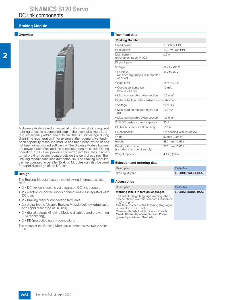
Overview
A Braking Module (and an external braking resistor) is required to bring drives to a controlled stop in the event of a line failure(e.g. emergency retraction) or to limit the DC link voltage during short-time regeneration if, for example, the regenerative feed-back capability of the line module has been deactivated or has not been dimensioned sufficiently. The Braking Module houses the power electronics and the associated control circuit. During operation, the DC link power is converted into heat loss in an ex-ternal braking resistor located outside the control cabinet. The Braking Module functions autonomously. The Braking Modulescan be operated in parallel. Braking Modules can also be used for rapid discharge of the DC link.
Design
The Braking Module features the following interfaces as stan-dard:• 2 x DC link connections via integrated DC link busbars• 2 x electronics power supply connections via integrated 24 V
DC bars• 2 x braking resistor connection terminals• 2 x digital inputs (disable Braking Module/acknowledge faults
and rapid discharge of DC link)• 2 x digital outputs (Braking Module disabled and prewarning
– I×t monitoring)• 2 x PE (protective earth) connections
The status of the Braking Modules is indicated via two 2-color LEDs.
Technical data
Selection and ordering data
Accessories
Braking Module
Rated power 1.5 kW (2 HP)
Peak power 100 kW (134 HP)
Max. current requirement (at 24 V DC)
0.2 A
Digital inputs
Voltage -3 V to +30 V
• Low level(an open digital input is interpreted as "low")
-3 V to +5 V
• High level 15 V to 30 V
• Current consumption(typ. at 24 V DC)
10 mA
• Max. connectable cross-section 1.5 mm2
Digital outputs (continuously-short-circuit-proof)
• Voltage 24 V DC
• Max. load current per digital out-put
100 mA
• Max. connectable cross-section 1.5 mm2
24 V DC busbar current capacity 20 A
DC link busbar current capacity 100 A
PE connection On housing with M5 screw
Width 50 mm (1.97 in)
Height 380 mm (14.96 in)
Depth, with spacer(included in scope of supply)
270 mm (10.63 in)
Weight, approx. 4.1 kg (9 lb)
Description Order No.
Braking Module 6SL3100-1AE31-0AA0
Description Order No.
Warning labels in foreign languagesThis set of foreign language warning labelscan be placed over the standard German orEnglish signs.One label in each of the following languages is provided in each set:Chinese, Danish, Dutch, Finnish, French,Greek, Italian, Japanese, Korean, Portu-guese, Spanish and Swedish.
6SL3166-3AB00-0AA0

SINAMICS S120 ServoDC link components
Braking Module
2/25Siemens D 21.2 · April 2004
2
Integration
Connection diagram for the Braking Module
R1
R2
X1X21
4
3
2
1
5M
6M
2
1
M
+
DCN
DCP
M
+
DCN
DCP
Braking Module
Braking resistor
DI, inhibit Braking Module
DI, DC link fast discharge
DO, "0 V" = Fault/Braking Module inhibited
G_D
212_
EN
_000
35c
24 V DC busbars
DC link busbars
Max. cable length: 10 m (32.8 ft)
DO, "0 V" = prewarning shutdown*

SINAMICS S120 ServoDC link components
Braking resistors
2/26 Siemens D 21.2 · April 2004
2
Overview
Excess power in the DC link is dissipated via the braking resistor.
The braking resistor is connected to a Braking Module. This means that the resulting heat loss can be dissipated outside of the control cabinet.
Two braking resistors with different rated and peak powers are available.
Technical data
Selection and ordering data
Braking resistor 0.3 kW (0.5 HP)/25 kW (33 HP)
Braking resistor 1.5 kW (2 HP)/100 kW (134 HP)
Rated power Prated kW (HP) 0.3 (0.5) 1.5 (2)
Peak power Pmax kW (HP) 25 (33) 100 (134)
Switch-on period for peak power
s 0.4 2
Braking duty cycle T duration
s 33 133
Degree of protec-tion
IP54 IP20
Width mm (inch)
80(3.15)
193(7.6)
Height mm (inch)
210(8.27)
410(16.14)
Depth mm (inch)
53(2.09)
240(9.45)
Weight, approx. kg (lb) 3.4 (7.5) 5.6 (12.3)
Description Order No.
Braking resistor 0.3 kW (0.5 HP)/25 kW (33 HP)
6SN1113-1AA00-0DA0
Braking resistor 1.5 kW (2 HP)/100 kW (134 HP)
6SL3100-1BE31-0AA0

SINAMICS S120 ServoDC link components
Capacitor Module
2/27Siemens D 21.2 · April 2004
2
Overview
Capacitor Modules are used to increase the DC link capacitance to bridge momentary power supply losses.
Capacitor Modules are connected to the DC link voltage via the integrated DC link busbars. Capacitor Modules function autono-mously.
Capacitor Modules can be operated in parallel.
Design
The Capacitor Module features the following interfaces as stan-dard:• 2 x DC link connections via integrated DC link busbars• 2 x PE (protective earth) connections
Technical data
Selection and ordering data
Accessories
Capacitor Module
Capacitance 4000 µF
24 V DC busbar current capacity 20 A
DC link busbar current capacity 100 A
PE connection On housing with M5 screw
Width 100 mm (3.94 in)
Height 380 mm (14.96 in)
Depth, with spacer(included in scope of supply)
270 mm (10.63 in)
Weight, approx. 7.2 kg (15.9 lb)
Description Order No.
Capacitor Module 6SL3100-1CE14-0AA0
Description Order No.
Warning labels in foreign languagesThis set of foreign language warning labelscan be placed over the standard German orEnglish signs.One label in each of the following languages is provided in each set:Chinese, Danish, Dutch, Finnish, French,Greek, Italian, Japanese, Korean, Portu-guese, Spanish and Swedish.
6SL3166-3AB00-0AA0

SINAMICS S120 ServoDC link components
Control Supply Module
2/28 Siemens D 21.2 · April 2004
2
Overview
The Control Supply Module provides a 24 V DC power supply via the line or DC link. This makes it possible, for example, to make emergency retraction movements in the event of the failure of the line supply, as long as the DC link voltage is available.
Design
The Control Supply Module features the following interfaces as standard:• 1 x power connection• 2 x DC link connections via integrated DC link busbars• 2 x electronics power supply connections via integrated 24 V
DC bars• 1 x connection for the electronics power supply for control
units, terminal modules, sensor modules, etc., via the 24 V ter-minal adapter provided in the scope of supply (max. cross-section 6 mm2, max. fuse protection 20 A)
• 2 x PE (protective earth) connections
The status of the Control Supply Modules is indicated via two multi-color LEDs.
Technical data
Selection and ordering data
Accessories
Control Supply Module
Rated input current
• at 3 AC 400 V 2.2 A
• at 600 V DC 1.1 A
Radio interference suppression (standard)
Class A1 to EN 55 011
Rated output voltage 26 V DC
Rated output current 20 A
24 V DC busbar current capacity 20 A
DC link busbar current capacity 100 A
Power connection L1, L2, L3 (X1) Screw-type terminals 0.2 mm2 to 4.0 mm2
PE connection On housing with M5 screw
Width 50 mm (1.97 in)
Height 380 mm (14.96 in)
Depth, with spacer (included in scope of supply)
270 mm (10.63 in)
Weight, approx. 4.8 kg (10.6 lb)
Description Order No.
Control Supply Module 6SL3100-1DE22-0AA0
Description Order No.
Warning labels in foreign languagesThis set of foreign language warning labelscan be placed over the standard German orEnglish signs.One label in each of the following languages is provided in each set:Chinese, Danish, Dutch, Finnish, French,Greek, Italian, Japanese, Korean, Portu-guese, Spanish and Swedish.
6SL3166-3AB00-0AA0

SINAMICS S120 ServoDC link components
DC link power supply adapter
2/29Siemens D 21.2 · April 2004
2
Overview
If the internal Motor Module DC link bus-baring is not to be used, the DC link voltage can be supplied externally using a DC link power supply adapter. Two versions are available depending on cable cross-section. The DC link power supply adapter is mounted on the DC link busbars of the Motor Module. The DC link cables are routed from above.
If a multi-tier Motor Module configuration is used, a DC link power supply adapter set can be provided for linking the DC links of two drive groups. The DC link power supply adapters are mounted on the DC link busbars of the Motor Modules on the far right of each group. The DC link cables are routed from behind.
Technical data
Selection and ordering data
DC link power supply adapter 6SL3162-
2BD00-0AA06SL3162-2BM00-0AA0
6SL3162-2BM01-0AA0
Connectablecross-section
0.5 to 10 mm2 35 to 95 mm2 35 to 95 mm2
Weight, approx.
0.06 kg(0.13 lb)
0.48 kg(1.06 lb)
0.76 kg(1.68 lb)
Description Order No.
DC link power supply adapterfor direct infeed of DC link voltageScrew-type terminals 0.5 mm2 to 10 mm2
for 50 mm (1.97 in) and 100 mm (3.94 in) Line and Motor Modules
6SL3162-2BD00-0AA0
DC link power supply adapterfor direct infeed of DC link voltageScrew-type terminals 35 mm2 to 95 mm2
for 150 mm (5.91 in), 200 mm (7.87 in) and 300 mm (11.81 in) Line and Motor Modules
6SL3162-2BM00-0AA0
DC link power supply adapter set(2 adapters)for multi-tier configurationScrew-type terminals 35 mm2 to 95 mm2
for all Line and Motor Modules in booksize format
6SL3162-2BM01-0AA0

SINAMICS S120 ServoControl Units
CU320 Control Unit
2/30 Siemens D 21.2 · April 2004
2
Overview
The communication, control functions for one or more Motor Modules and Active Line Modules run in a CU320 Control Unit. The Control Units are designed as standard for multi-axis oper-ation.
Design
CU320 Control Unit, without cover
The CU320 Control Unit features the following interfaces as stan-dard: • 4 x DRIVE-CLiQ sockets for communication with other DRIVE-
CLiQ devices, e.g. Motor Modules, Active Line Modules, Sen-sor Modules, Terminal Modules
• 1 x PROFIBUS interface• 8 x parameterizable digital inputs (floating)
8 x parameterizable bidirectional digital inputs/digital outputs (non-floating), of which 6 are high-speed digital inputs
• 1 x serial RS232 interface• 1 x option slot• 3 x test sockets and one reference ground for start-up support• 1 x connection for the electronics power supply via the 24 V
DC power supply connector• 1 x PE (protective earth) connection• 1 x ground connection
A shield connection for the signal cable shield on the option module is located on the CU320 Control Unit.
The available option slot is used to expand the interfaces, for ex-ample, to include additional terminals or for communication pur-poses.
The status of the CU320 Control Unit is indicated via multi-color LEDs.
As the firmware and parameter settings are stored on a plug-inCompactFlash Card, the Control Unit can be changed withoutthe need for additional tools.
The CU320 Control Unit can be mounted on the side of the line module using brackets integrated in a Line Module. The CU320 Control Unit can also be fixed to the back wall of the control cab-inet using the integrated fixing lugs. As the CU320 Control Unitis not as deep as the Line Modules, suitable spacers are avail-able to increase the depth of the CU320 Control Unit to 270 mm (10.63 in).
Integration
DRIVE-CLiQ components, for example, Motor Modules and Ac-tive Line Modules, can be connected to a CU320 Control Unit. The number of modules depends on the performance required, including mode type and additional functions.
Communication between a CU320 Control Unit and the con-nected components takes place via DRIVE-CLiQ.
If an application requires more than one Control Unit, the number can be increased accordingly. The Control Units are then inter-connected, for example, via PROFIBUS on a higher-level con-troller.
SINAMICS S120 ServoControl Units
CU320 Control Unit
2/31Siemens D 21.2 · April 2004
2
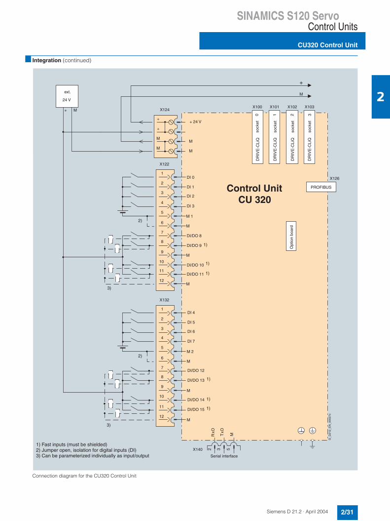
Integration (continued)
Connection diagram for the CU320 Control Unit
+
RxD
TxD
M
MX103X102
1
X101X100
PROFIBUS
X126
DR
IVE
-CLi
Q
DR
IVE
-CLi
Q
0
DR
IVE
-CLi
QO
ptio
n bo
ard
2
DR
IVE
-CLi
Q3
M
+
3)
3)
532
2)
2)
DI 0
X122
4
3
2
1
DI 1
DI 3
DI 2
5M 1
M6
DI/DO 8 7
8
9
10
11
12
DI/DO 9
DI/DO 10
DI/DO 11
M
M
DI 4
X132
4
3
2
1
DI 5
DI 7
DI 6
5M 2
M6
DI/DO 12 7
8
9
10
11
12
DI/DO 13
DI/DO 14
DI/DO 15
M
M
+ 24 V
M
X124
M
+
M
+
M
1)
1)
1)
1)
1)
1)
X140
Control UnitCU 320
1) Fast inputs (must be shielded)2) Jumper open, isolation for digital inputs (DI)3) Can be parameterized individually as input/output
G_D
212_
EN
_000
27c
Serial interface
ext.
24 V
sock
et
sock
et
sock
et
sock
et

SINAMICS S120 ServoControl Units
CU320 Control Unit
2/32 Siemens D 21.2 · April 2004
2
Technical data Selection and ordering data
Accessories
CU320 Control Unit
Max. current requirement (at 24 V DC)without taking account of digital out-puts, option slot expansion
0.8 A
Max. connectable cross-section 2.5 mm2
Max. fuse protection 20 A
Digital inputs 8 x floating digital inputs8 x bidirectional non-floating digi-tal inputs/digital outputs
• Voltage -3 V to 30 V
• Low level(an open digital input is interpreted as "low")
-3 V to 5 V
• High level 15 V to 30 V
• Current consumption(typ. at 24 V DC)
10 mA
• Signal propagation delays for digi-tal inputs
L → H: approx. 50 µsH → L: approx. 100 µs
• Signal propagation delays for high-speed digital inputs(high-speed digital inputs can beused for position detection)
L → H: approx. 5 µsH → L: approx. 50 µs
• Max. connectable cross-section 0.5 mm2
Digital outputs (continuously-short-circuit-proof)
8 x bidirectional non-floating digi-tal outputs/digital inputs
• Voltage 24 V DC
• Max. load current per digital out-put
500 mA
• Max. connectable cross-section 0.5 mm2
Power loss 20 W
PE connection On housing with M5 screw
Ground connection On housing with M5 screw
Width 50 mm (1.97 in)
Height 270 mm (10.63 in)
Depth 226 mm (8.9 in)
Weight, approx. 1.5 kg (3.3 lb)
Description Order No.
CU320 Control Unit (excluding Compact-Flash Card)
6SL3040-0MA00-0AA1
Description Order No.
PROFIBUS connectorwithout PG/PC connection
6ES7972-0BA41-0XA0
PROFIBUS connectorwith PG/PC connection
6ES7972-0BB41-0XA0
Spacers (2 x) for increasing the depth of the CU320 Control Unit to 270 mm (10.63 in) (if the brackets on the side are not to be used but the depth still has to be 270 mm (10.63 in)).
6SL3064-1BB00-0AA0

SINAMICS S120 ServoControl Units
CompactFlash card
2/33Siemens D 21.2 · April 2004
2
Overview
The firmware and parameter settings are stored on the Com-pactFlash Card, which is plugged into the CU320 Control Unit.
Design
The performance of the firmware on the CompactFlash Card is scalable. The "Performance Extension 1" firmware option can beused to extend the performance of the CompactFlash Card with-out performance extension.
The use of Performance Extension 1 increases computing power by 100%.
The required performance depends on the number of drives to be used on the Control Unit and their functional scope and dy-namics.
The SIZER configuration tool can be used to calculate exact per-formance requirements. The firmware options are supplied in li-cense form, which are written to the CompactFlash Card in the factory as license codes.
The firmware option can also be enabled on-site, for example, if the performance extension required is not known at the time ofplacing the order. You will need the serial number of the Com-pactFlash Card and the order number of the firmware option to be enabled. With this information you can purchase the associ-ated license code from a license database and enable the firm-ware option. The license code is only valid for the CompactFlash Card declared and cannot be transferred to other CompactFlash Cards.
Selection and ordering data
The current firmware version is always supplied with the above CompactFlash Cards.
The firmware version is encoded in the order number of the CompactFlash Card supplied. This means that the order num-bers of the CompactFlash Cards ordered and delivered may not be identical.
Example: A CompactFlash Card is ordered using the order num-ber 6SL3054-0AA00-1AA0 (as specified in the catalog) and aCompactFlash Card with the current firmware version, e.g. order number 6SL3054-0CB00-1AA0 for firmware version 2.1, is con-firmed and delivered. This means that in the event of a replace-ment, a specific firmware version can be ordered.
Description Order No.
CompactFlash Cardwith current firmware version including certifi-cate of licensewithout performance extension
6SL3054-0AA00-1AA0
CompactFlash Cardwith current firmware version including certifi-cate of licensewith Performance extension 1 firmware option
6SL3054-0AA01-1AA0
Firmware licensePerformance extension 1firmware option for CompactFlash Card including certificate of license
6SL3074-0AA01-0AA0
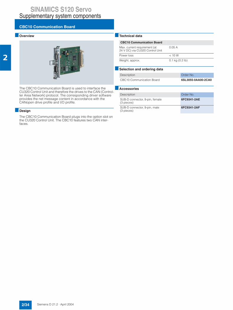
SINAMICS S120 ServoSupplementary system components
CBC10 Communication Board
2/34 Siemens D 21.2 · April 2004
2
Overview
The CBC10 Communication Board is used to interface the CU320 Control Unit and therefore the drives to the CAN (Control-ler Area Network) protocol. The corresponding driver software provides the net message content in accordance with the CANopen drive profile and I/O profile.
Design
The CBC10 Communication Board plugs into the option slot on the CU320 Control Unit. The CBC10 features two CAN inter-faces.
Technical data
Selection and ordering data
Accessories
CBC10 Communication Board
Max. current requirement (at 24 V DC) via CU320 Control Unit
0.05 A
Power loss < 10 W
Weight, approx. 0.1 kg (0.2 lb)
Description Order No.
CBC10 Communication Board 6SL3055-0AA00-2CA0
Description Order No.
SUB-D connector, 9-pin, female(3 pieces)
6FC9341-2AE
SUB-D connector, 9-pin, male(3 pieces)
6FC9341-2AF

SINAMICS S120 ServoSupplementary system components
TB30 Terminal Board
2/35Siemens D 21.2 · April 2004
2
Overview
The TB30 Terminal Board expands the number of digital in-puts/digital outputs and analog inputs/analog outputs of the CU320 Control Unit.
Design
The following interfaces are located on the TB30 Terminal Board:• Power supply for digital inputs/digital outputs• 4 x digital inputs• 4 x digital outputs• 2 x analog inputs• 2 x analog outputs
The TB30 Terminal Board plugs into the option slot on the CU320 Control Unit.
A shield connection for the signal cable shield is located on the CU320 Control Unit.
Technical data
Selection and ordering data
TB30 Terminal Board
Max. current requirement (at 24 V DC) via CU320 Control Unit without taking account of the digital outputs
0.05 A
Max. connectable cross-section 2.5 mm2
Max. fuse protection 20 A
Digital inputs
• Voltage -3 V to +30 V
• Low level(an open digital input is interpreted as "low")
-3 V to +5 V
• High level 15 V to 30 V
• Current consumption(at 24 V DC)
typ. 10 mA
• Signal propagation delays for digi-tal inputs
L → H: approx. 50 µsH → L: approx. 100 µs
• Max. connectable cross-section 0.5 mm2
Digital outputs (continuously-short-circuit-proof)
• Voltage 24 V DC
• Max. load current per digital out-put
500 mA
• Max. connectable cross-section 0.5 mm2
Analog inputs (differential)
• Voltage range(an open analog input is interpret-ed as 0 V)
-10 V to +10 V
• Internal resistance Ri 65 kΩ
• Resolution 13 bit + sign
• Max. connectable cross-section 0.5 mm2
Analog outputs (continuously-short-circuit-proof)
• Voltage range -10 V to +10 V
• Max. load current -3 mA to +3 mA
• Resolution 11 bit + sign
• Max. connectable cross-section 0.5 mm2
Power loss < 3 W
Weight, approx. 0.1 kg (0.2 lb)
Description Order No.
TB30 Terminal Board 6SL3055-0AA00-2TA0
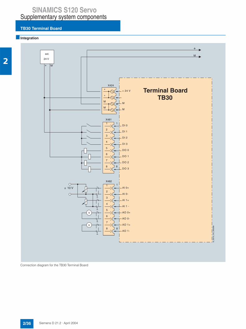
SINAMICS S120 ServoSupplementary system components
TB30 Terminal Board
2/36 Siemens D 21.2 · April 2004
2
Integration
Connection diagram for the TB30 Terminal Board
+ M
+ 24 V
M
X424
M
+
M
+
M
V
V
AI 0+
AI 0-
AI 1 -
AI 1+
AO 0+
AO 0-
AO 1+
AO 1-
X4821
8
4
3
2
1
5
6
7
8
± 10 V
X48111
DI 0
DI 1
DI 3
DI 2
DO 0
8
DO 1
DO 2
DO 3
4
3
2
5
6
7
8
G_D
212_
XX
_000
28b
M
+ext.
24 V
Terminal BoardTB30

SINAMICS S120 ServoSupplementary system components
TM31 Terminal Module
2/37Siemens D 21.2 · April 2004
2
Overview
With the TM31 Terminal Module, the number of available digital inputs and outputs and the number of analog input and outputs within a drive can be expanded.
Design
The following interfaces are located on the TM31 Terminal Module:• 8 x digital inputs• 4 x bidirectional digital inputs/digital outputs• 2 x relay outputs with change-over contact• 2 x analog inputs• 2 x analog outputs• 1 x temperature sensor input (KTY84-130 or PTC)• 2 x DRIVE-CLiQ sockets• 1 x connection for the electronics power supply via the 24 V
DC power supply connector• 1 x PE (protective earth) connection
The TM31 Terminal Module can be snapped onto a 35 x 15/7.5 (1.4 x 0.6/0.3) DIN rail to EN 50 022.
The signal line shield can be connected to the TM31 Terminal Module via a shield connection terminal, e.g. Phoenix Contacttype SK8 or Weidmüller type KLBÜ CO 1. The shield connection terminal must not be used for strain relief.
The status of the TM31 Terminal Module is indicated via a multi-color LED.
Technical data
Technical data (continued)
Selection and ordering data
TM31 Terminal Module
Max. current requirement (at 24 V DC) without taking account of digital outputs
0.5 A
Max. connectable cross-section 2.5 mm2
Max. fuse protection 20 A
Digital inputs
• Voltage -3 V to +30 V
TM31 Terminal Module
• Low level(an open digital input is interpreted as "low")
-3 V to +5 V
• High level 15 V to 30 V
• Current consumption(at 24 V DC)
typ. 10 mA
• Signal propagation delaysfor digital inputs
L → H: ca. 50 µsH → L: ca. 100 µs
• Max. connectable cross-section 1.5 mm2
Digital outputs (continuously-short-circuit-proof)
• Voltage 24 V DC
• Max. load current per digital out-put
100 mA
• Max. total current of digital outputs 400 mA
• Max. connectable cross-section 1.5 mm2
Analog inputs (a switch is used to toggle between voltage and currentinput)
• As voltage input
- Voltage range -10 V to +10 V
- Internal resistance Ri 100 kΩ
• As current input
- Current range 4 mA to 20 mA/-20 mA to+20 mA/ 0 mA to 20 mA
- Internal resistance Ri 250 Ω
- Resolution 11 bit + sign
• Max. connectable cross-section 1.5 mm2
Analog outputs (continuously-short-circuit-proof)
• Voltage range -10 V to +10 V
• Max. load current -3 mA to +3 mA
• Current range 4 mA to 20 mA, -20 mA to+20 mA, 0 mA to 20 mA
• Max. load resistance 500 Ω for outputs in the range-20 mA to +20 mA
• Resolution 11 bit + sign
• Max. connectable cross-section 1.5 mm2
Relay outputs (change-over contacts)
• Max. load current 8 A
• Max. switching voltage 250 V AC, 30 V DC
• Max. switching power (at 250 V AC )
2000 VA (cos ϕ = 1)750 VA (cos ϕ = 0.4)
• Max. switching power (at 30 V DC )
240 W (ohmic load)
• Required minimum current 100 mA
• Max. connectable cross-section 2.5 mm2
Power loss < 10 W
PE connection On housing with M4 screw
Width 50 mm (1.97 in)
Height 150 mm (5.91 in)
Depth 111 mm (4.37 in)
Weight, approx. 0.87 kg (1.9 lb)
Description Order No.
TM31 Terminal Module(without DRIVE-CLiQ cable)
6SL3055-0AA00-3AA0

SINAMICS S120 ServoSupplementary system components
TM31 Terminal Module
2/38 Siemens D 21.2 · April 2004
2
Integration
The TM31 Terminal Module communicates with the CU320Control Unit via DRIVE-CLiQ.
Connection diagram for the TM31 Terminal Module
X501X500
DI 0
4
3
2
1
DI 1
DI 3
DI 2
5M1
6M
X520
+ 24 V
4
3
2
1
+ 24 V
+ 24 V
+ 24 V
5+ 24 V
+ 24 V6
+ 24 V7
8+ 24 V
X540
DI 4
4
3
2
1
DI 5
DI 7
DI 6
5M 2
6M
X530
1)
1)
AI 0+
4
3
2
1
AI 0-
AI 1-
AI 1+
5P10
6M
X521
7N10
M8
AO 0V+
4
3
2
1
AO 0-
AO 1V+
AO 0C+
5AO 1-
6AO 1C+
X522
7+ Temp
- Temp8
V
V
4
3
2
1
DO 0
5DO 1
6
X542
+ 24 V
M
X524
M
+
M
+
M
M
+
M
+
X541
DI/DO 8
1
2
3
4
5
6
DI/DO 9
DI/DO 11
+
DI/DO 10
M
2)
3)
1
DR
IVE
-CLi
Q
DR
IVE
-CLi
Q
0
A
A
Terminal ModuleTM31
1) In this example, the jumpersmust be inserted
2) Can be parameterized individually
Can be parameterized individually as outputas current source
3)
G_D212_EN_00029b
sock
et
sock
et
SINAMICS S120 ServoEncoder system connection
Encoder system connection
2/39Siemens D 21.2 · April 2004
2
Overview
Encoder systems can only be connected to SINAMICS S120 via DRIVE-CLiQ.
Motors with DRIVE-CLiQ interfaces can be ordered for this pur-pose, for example, 1FK7 and 1FT6 synchronous motors and 1PH7 asynchronous motors. Each of these motors can be sup-plied as standard with one DRIVE-CLiQ interface.
These motors with DRIVE-CLiQ interface can be connected to the corresponding motor module directly via the MOTION-CON-NECT DRIVE-CLiQ cables available. This connection route is used to transmit motor encoder and temperature signals as well as electronic rating plate data such as unique ID numbers, rated data (voltage, current, torque) directly to the Control Unit. These motors make start-up and diagnostics much easier, as the motor and encoder type can be identified automatically.
Motors without DRIVE-CLiQ interface
The encoder and temperature signals of motors without DRIVE-CLiQ interfaces, as well as those of external encoders, must be connected via Sensor Modules. Sensor Modules Cabinet-mounted with IP20 degree of protection are currently availablefor direct installation in control cabinets.
Only one encoder can be connected to each Sensor Module Cabinet-mounted.
Technical data
Further information
If possible, motor encoder and temperature signals should be connected to the corresponding Motor Module and external en-coders to the Control Unit.
Motors with DRIVE-CLiQ interface andresolver(2-pole/multi-pole)
Motors with DRIVE-CLiQ interface andincremental encodersin/cos 1 Vpp, abso-lute encoder EnDat (512 S/R, 2048 S/R)or single absoluteencoder
Max. current require-ment at 24 V DC (via Motor Module and MOTION-CONNECTDRIVE-CLiQ cable)
500 mA 500 mA
Max. DRIVE-CLiQ cable length betweenmotor and Motor Mod-ules
• 100 m (328 ft) when using MOTION-CONNECT 500 DRIVE-CLiQ cables
• 50 m (164 ft) when using MOTION-CONNECT 800 DRIVE-CLiQ cables

SINAMICS S120 ServoEncoder system connection
SMC10 Sensor Module Cabinet-mounted
2/40 Siemens D 21.2 · April 2004
2
Overview
SMC10 Sensor Modules Cabinet-mounted are required when a motor with a DRIVE-CLiQ interface is not available or when ex-ternal encoders are required in addition to the motor encoder.
The following encoder signals can be evaluated:• 2-pole resolver• Multi-pole resolver
Design
The SMC10 Sensor Module Cabinet-mounted features thefollowing interfaces as standard:• 1 x DRIVE CLiQ interface• 1 x encoder connection including motor temperature detec-
tion (KTY84-130) via SUB-D connector• 1 x connection for the electronics power supply via the 24 V
DC power supply connector• 1 x PE (protective earth) connection
The status of the SMC10 Sensor Module Cabinet-mounted is in-dicated via a multi-color LED.
SMC10 Sensor Modules Cabinet-mounted can be snapped onto a 35 × 15/7.5 (1.4 × 0.6/0.3) DIN rail to EN 50 022.
The maximum encoder cable length between SMC10 Modules and encoders is:• For 2-pole resolvers: 130 m (427 ft)• For multi-pole resolvers: 50 m (164 ft)
Integration
The SMC10 Sensor Module Cabinet-mounted communicates with the CU320 Control Unit via DRIVE-CLiQ.
Technical data
Selection and ordering data
SMC10 Sensor Module Cabinet-mounted
Max. current requirement (at 24 V DC)without taking account of encoder
0.3 A
Max. connectable cross-section 2.5 mm2
Max. fuse protection 20 A
Power loss < 10 W
PE connection On housing with M4 screw
Width 50 mm (1.97 in)
Height 150 mm (5.91 in)
Depth 111 mm (4.37 in)
Weight, approx. 0.8 kg (1.9 lb)
Description Order No.
SMC10 Sensor Module Cabinet-mounted(excluding DRIVE-CLiQ cable)
6SL3055-0AA00-5AA0
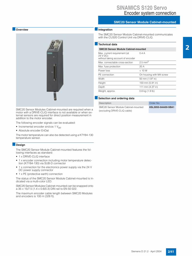
SINAMICS S120 ServoEncoder system connection
SMC20 Sensor Module Cabinet-mounted
2/41Siemens D 21.2 · April 2004
2
Overview
SMC20 Sensor Modules Cabinet-mounted are required when a motor with a DRIVE-CLiQ interface is not available or when ex-ternal sensors are required for direct position measurement inaddition to the motor encoder.
The following encoder signals can be evaluated:• Incremental encoder sin/cos 1 Vpp• Absolute encoder EnDat
The motor temperature can also be detected using a KTY84-130 temperature sensor.
Design
The SMC20 Sensor Module Cabinet-mounted features the fol-lowing interfaces as standard:• 1 x DRIVE-CLiQ interface• 1 x encoder connection including motor temperature detec-
tion (KTY84-130) via SUB-D connector• 1 x connection for the electronics power supply via the 24 V
DC power supply connector• 1 x PE (protective earth) connection
The status of the SMC20 Sensor Module Cabinet-mounted is in-dicated via a multi-color LED.
SMC20 Sensor Modules Cabinet-mounted can be snapped onto a 35 × 15/7.5 (1.4 × 0.6/0.3) DIN rail to EN 50 022.
The maximum encoder cable length between SMC20 Modules and encoders is 100 m (328 ft).
Integration
The SMC20 Sensor Module Cabinet-mounted communicates with the CU320 Control Unit via DRIVE-CLiQ.
Technical data
Selection and ordering data
SMC20 Sensor Module Cabinet-mounted
Max. current requirement (at 24 V DC)without taking account of encoder
0.4 A
Max. connectable cross-section 2.5 mm2
Max. fuse protection 20 A
Power loss < 10 W
PE connection On housing with M4 screw
Width 50 mm (1.97 in)
Height 150 mm (5.91 in)
Depth 111 mm (4.37 in)
Weight, approx. 0.8 kg (1.9 lb)
Description Order No.
SMC20 Sensor Module Cabinet-mounted(excluding DRIVE-CLiQ cable)
6SL3055-0AA00-5BA1

SINAMICS S120 ServoEncoder system connection
SMC30 Sensor Module Cabinet-mounted
2/42 Siemens D 21.2 · April 2004
2
Overview
SMC30 Sensor Modules Cabinet-mounted are required when a motor with a DRIVE-CLiQ interface is not available or when ex-ternal sensors are required in addition to the motor encoder.
TTL/HTL incremental encoders with and without cable-break detection are supported.
The motor temperature can also be detected using KTY84-130 temperature sensors.
Design
The SMC30 Sensor Module Cabinet-mounted features the fol-lowing interfaces as standard:• 1 x DRIVE-CLiQ interface• 1 x encoder connection including motor temperature detec-
tion (KTY84-130) via SUB-D connector or terminals• 1 x connection for the electronics power supply via the 24 V
DC power supply connector• 1 x PE (protective earth) connection
The status of the SMC30 Sensor Module Cabinet-mounted is in-dicated via a multi-color LED.
SMC30 Sensor Modules Cabinet-mounted can be snapped onto a 35 × 15/7.5 (1.4 × 0.6/0.3) DIN rail to EN 50 022.
The maximum encoder cable length between SMC30 Modules and encoders is 100 m (328 ft). For HTL encoders, this length can be increased to 300 m (985 ft) if signals A+/A- and B+/B- are evaluated and the power supply cable has a minimum cross-section of 0.75 mm2.
The signal line shield can be connected to the SMC30 Sensor Module Cabinet-mounted via a shield connection terminal, e.g.Phoenix Contact type SK8 or Weidmüller type KLBÜ CO 1. The shield connection terminal must not be used for strain relief.
Integration
The SMC30 Sensor Module Cabinet-mounted communicates with the CU320 Control Unit via DRIVE-CLiQ.
Technical data
Selection and ordering data
SMC30 Sensor Module Cabinet-mounted
Max. current requirement (at 24 V DC)without taking account of encoder
0.6 A
Max. connectable cross-section 2.5 mm2
Max. fuse protection 20 A
Power loss < 10 W
PE connection On housing with M4 screw
Width 50 mm (1.97 in)
Height 150 mm (5.91 in)
Depth 111 mm (4.37 in)
Weight, approx. 0.8 kg (1.9 lb)
Description Order No.
SMC30 Sensor Module Cabinet-mounted(excluding DRIVE-CLiQ cable)
6SL3055-0AA00-5CA0
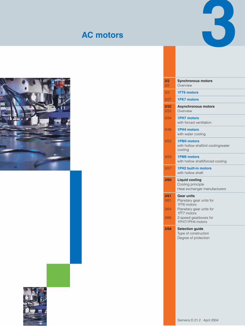
Siemens D 21.2 · April 2004
3/2 Synchronous motors3/2 Overview
3/3 1FT6 motors
3/27 1FK7 motors
3/32 Asynchronous motors3/32 Overview
3/34 1PH7 motorswith forced ventilation
3/48 1PH4 motorswith water cooling
3/52 1PM4 motorswith hollow shaft/oil cooling/water cooling
3/53 1PM6 motorswith hollow shaft/forced cooling
3/57 1PH2 built-in motorswith hollow shaft
3/60 Liquid coolingCooling principleHeat exchanger manufacturers
3/61 Gear units3/61 Planetary gear units for
1FT6 motors3/64 Planetary gear units for
1FT7 motors3/66 2-speed gearboxes for
1PH7/1PH4 motors
3/68 Selection guideType of constructionDegree of protection
AC motors
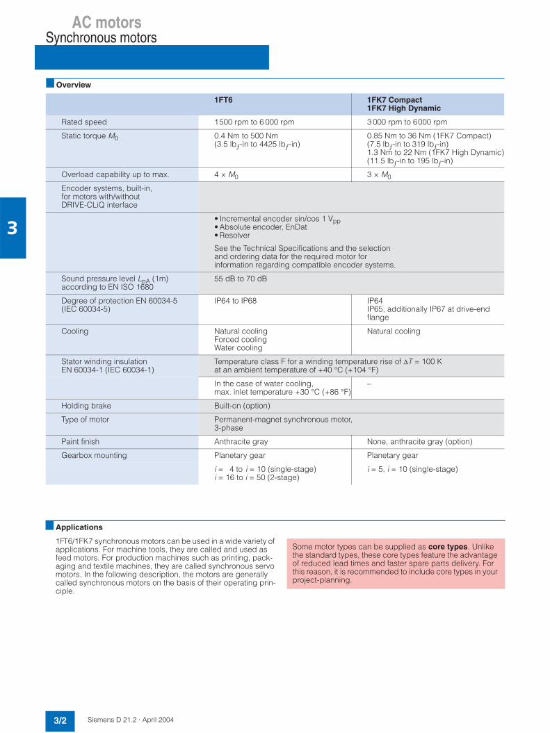
AC motorsSynchronous motors
3/2 Siemens D 21.2 · April 2004
3
Overview
1FT6 1FK7 Compact1FK7 High Dynamic
Rated speed 1500 rpm to 6 000 rpm 3 000 rpm to 6000 rpm
Static torque M0 0.4 Nm to 500 Nm(3.5 lbƒ-in to 4425 lbƒ-in)
0.85 Nm to 36 Nm (1FK7 Compact)(7.5 lbƒ-in to 319 lbƒ-in)1.3 Nm to 22 Nm (1FK7 High Dynamic)(11.5 lbƒ-in to 195 lbƒ-in)
Overload capability up to max. 4 × M0 3 × M0
Encoder systems, built-in, for motors with/without DRIVE-CLiQ interface
• Incremental encoder sin/cos 1 Vpp• Absolute encoder, EnDat• Resolver
See the Technical Specifications and the selection and ordering data for the required motor forinformation regarding compatible encoder systems.
Sound pressure level LpA (1m) according to EN ISO 1680
55 dB to 70 dB
Degree of protection EN 60034-5(IEC 60034-5)
IP64 to IP68 IP64IP65, additionally IP67 at drive-end flange
Cooling Natural coolingForced coolingWater cooling
Natural cooling
Stator winding insulationEN 60034-1 (IEC 60034-1)
Temperature class F for a winding temperature rise of ∆T = 100 Kat an ambient temperature of +40 °C (+104 °F)
In the case of water cooling,max. inlet temperature +30 °C (+86 °F)
–
Holding brake Built-on (option)
Type of motor Permanent-magnet synchronous motor, 3-phase
Paint finish Anthracite gray None, anthracite gray (option)
Gearbox mounting Planetary gear Planetary gear
i = 4 to i = 10 (single-stage)i = 16 to i = 50 (2-stage)
i = 5, i = 10 (single-stage)
Applications
1FT6/1FK7 synchronous motors can be used in a wide variety of applications. For machine tools, they are called and used as feed motors. For production machines such as printing, pack-aging and textile machines, they are called synchronous servo motors. In the following description, the motors are generally called synchronous motors on the basis of their operating prin-ciple.
Some motor types can be supplied as core types. Unlike the standard types, these core types feature the advantageof reduced lead times and faster spare parts delivery. For this reason, it is recommended to include core types in your project-planning.

AC motorsSynchronous motors
1FT6 motors
3/3Siemens D 21.2 · April 2004
3
AC motors
Overview
1FT6 motors are compact permanent-magnet synchronous mo-tors.1FT6 motors with built-in encoders can be operated on theSINAMICS S drive system.
The fully digital control system of the SINAMICS S drive system and the encoder technology of the 1FT6 motors fulfill the highest demands in terms of dynamic performance, speed setting range and rotational and positioning accuracy.
The motors are primarily designed for operation without external cooling and the heat is dissipated via the motor surface. Theheat generated in the stator winding and stator core is directly dissipated via the good thermal coupling to the motor enclosure. The concept of brushless, permanent-field synchronous motors shows its special merits here.
Benefits7 Optimum workpiece surface quality due to high rotational ac-
curacy (sinusoidal current injection)7 Short non-productive times due to high dynamic performance7 Power and signal connections for use in severely contaminat-
ed areas7 Simple installation due to reduced cabling requirements7 High resistance to lateral forces
Applications
• High-performance machine tools
• Production machines with high demands in terms of dynamic performance and precision
Technical data
1) A max. operating frequency of 470 Hz must be observed withSINAMICS.
Type of motor Permanent-magnet synchronous motor
Magnetic material Rare-earth magnetic material
Insulation of the stator windingin accordance with EN 60034-1(IEC 60034-1)
Temperature class F for a winding temperature rise of ∆T = 100 K at an ambient temperature of +40 °C (+104°F)In the case of water cooling,inlet temperature• max. +30 °C (+86 °F)
Type according toEN 60034-7 (IEC 60034-7)
IM B5 (IM V1, IM V3)IM B14 (IM V18, IM V19)IM B35 on 1FT613.
Degree of protection according toEN 60034-5 (IEC 60034-5)
IP64 standard type, IP65 coretype
Cooling Natural air cooling, separateventilation, water cooling
Temperature monitoring KTY 84 temperature sensor in stator winding
Paint finish Anthracite gray
2nd rating plate Supplied separately packed
Shaft end on the drive end in accordance with DIN 748-3 (IEC 60072-1)
Smooth shaft
Radial eccentricity, concentricity, and axial eccentricityin accordance with DIN 42955(IEC 60072-1)
Tolerance N (normal)
Vibration severity in accordance with EN 60034-14 (IEC 60034-14)
Level N (normal)
Max. sound pressure level LpA(1 m) acc. to EN ISO 1680
1FT602: 55 dB1FT603/1FT604: 55 dB1FT606: 65 dB1FT608/1FT610/1FT613: 70 dB
Encoder systems, built-in, for motors with/withoutDRIVE-CLiQ interface
• Incremental encoder sin/cos1 Vpp 2048 S/R
• Absolute encoder, multiturn, 2048 S/R on 1FT603 to 1FT613. 512 S/R on 1FT602 and traversing range 4096 revo-lutions with EnDat interface
• Multipole resolver 1)
(number of poles corresponds to number of pole pairs of the motor)
• 2-pole resolver
Connecting Connectors for signals and powerTerminal box possible on 1FT61.
Options • Shaft end on the drive end with featherkey and key way (half-key balancing)
• Built-in holding brake• Degree of protection IP67, IP68
M5 sealing air connection present (except with forced ventilation)
• Planetary gear units, built-on(requirement: smooth shaft end) and vibration severity grade N)
• Terminal box for power terminal

AC motorsSynchronous motors
Core type 1FT6 motors with natural cooling
3/4 Siemens D 21.2 · April 2004
3
Selection/Ordering data
Ratedspeed
ShaftheightSH
Ratedpower
Statictorque
Ratedtorque 1)
Ratedcurrent
1FT6 synchronous motorswith natural cooling
No.of polepairs
Rotor moment of inertia (excludingbrake)
Weight (excludingbrake)
nrated Pratedat∆T=100 K
M0at∆T=100 K
Mratedat∆T=100 K
Iratedat∆T=100 K
Order No.Core type
J m
rpm kW(HP)
Nm(lbƒ-in)
Nm(lbƒ-in)
A 10-4 kg m2
(lbƒ-in-s2)kg(lb)
2000 100 4.8 (6.43)8 (10.72)
27 (239)50 (442.6)
2338
(203.6)(336.3)
1117.6
1FT6 102 - 1AC71 - 7 7 7 11FT6 105 - 1AC71 - 7 7 7 1
44
99 (0.0876)168 (0.1487)
27.5 (60.6)39.5 (87.1)
3000 48 1.4 (1.88) 5 (44.3) 4.3 (38.1) 2.9 1FT6 044 - 1AF71 - 7 7 7 1 2 5.1(0.0045) 8.3 (18.3)
63 1.5 (2.01)2.2 (2.95)
6 (53.1)9.5 (84.1)
4.77
(41.6)(62)
3.44.9
1FT6 062 - 1AF71 - 7 7 7 11FT6 064 - 1AF71 - 7 7 7 1
33
8.5(0.0752)13 (0.0115)
9.5 (20.9)12.5 (27.6)
80 3.2 (4.29)4.6 (6.17)5.8 (7.77)
13 (115.1)20 (177)27 (239)
10.314.718.5
(91.2)(130.1)(163.7)
8.71113
1FT6 082 - 1AF71 - 7 7 7 11FT6 084 - 1AF71 - 7 7 7 11FT6 086 - 1AF71 - 7 7 7 1
444
30 (0.0266)48 (0.0425)66.5(0.0589)
15 (33.1)20.5 (45.2)25.5 (56.2)
4500 63 1.7 (2.28)2.3 (3.08)
6 (53.1)9.5 (84.1)
3.64.8
(31.9)(42.5)
3.95.5
1FT6 062 - 1AH71 - 7 7 7 11FT6 064 - 1AH71 - 7 7 7 1
33
8.5(0.0752)13 (0.0115)
9.5 (20.9)12.5 (27.6)
80 4.9 (6.57)5.7 (7.64)
20 (177)27 (239)
10.512
(92.9)(106.2)
12.512.6
1FT6 084 - 1AH71 - 7 7 7 11FT6 086 - 1AH71 - 7 7 7 1
44
48 (0.0425)66.5(0.0589)
20.5 (45.2)25.5 (56.2)
6000 36 0.88 (1.18) 2 (17.7) 1.4 (12.4) 2.1 1FT6 034 - 1AK71 - 7 7 7 1 2 1.1(0.001) 4.4 (9.7)
80 4.1 (5.5) 20 (177) 6.5 (57.5) 9.2 1FT6 084 - 1AK71 - 7 7 7 1 4 48 (0.0425) 20.5 (45.2)
• Connector outlet direction: Transverse right (not for 1FT604, 1FT606)Transverse left (not for 1FT604, 1FT606)Axial NDEAxial DE
• Encoder systems for motors without DRIVE-CLiQ interface:
Incremental encoder sin/cos 1 Vpp, 2048 S/RAbsolute encoder EnDat 2048 S/R 1)
• Encoder systems for motors with DRIVE-CLiQ interface:
Incremental encoder sin/cos 1 Vpp, 2048 S/RAbsolute encoder EnDat 2048 S/R 1)
DF
• Smooth shaft/rotational accuracy tolerance N:
Without holding brakeWith holding brake
1234
AE
GH
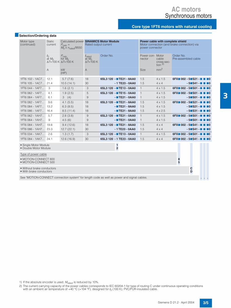
AC motorsSynchronous motors
Core type 1FT6 motors with natural cooling
3/5Siemens D 21.2 · April 2004
3
Selection/Ordering data
1) If the absolute encoder is used, Mrated is reduced by 10%.2) The current carrying capacity of the power cables corresponds to IEC 60204-1 for type of routing C under continuous operating conditions
with an ambient air temperature of +40 °C (+104 °F), designed for I0 (100 K), PVC/PUR-insulated cable.
Motor type(continued)
Staticcurrent
Calculated powerPcalc =M0 x nrated/9550
SINAMICS Motor ModuleRated output current
Power cable with complete shieldMotor connection (and brake connection) via power connector
I0at M0∆T=100 K
Pcalcfor M0∆T=100 K
Iratedat M0∆T=100 K
Order No. Power con-nector
Motorcablecross-sec-tion 2)
Order No.Pre-assembled cable
A kW(HP)
A Size mm2
1FT6 102 - 1AC7...1FT6 105 - 1AC7...
12.121.4
5.7 (7.6)10.5 (14.1)
1830
6SL3 120 - 7TE21 - 8AA0- 1 TE23 - 0AA0
1.51.5
4 x 1.54 x 4
6FX7 002 - 57S21 - 7 7 70- 57S41 - 7 7 70
1FT6 044 - 1AF7... 3 1.6 (2.1) 3 6SL3 120 - 7TE13 - 0AA0 1 4 x 1.5 6FX7 002 - 57S01 - 7 7 70
1FT6 062 - 1AF7...1FT6 064 - 1AF7...
4.16.1
1.9 (2.5)3 (4)
59
6SL3 120 - 7TE15 - 0AA0- 7TE21 - 0AA0
11
4 x 1.54 x 1.5
6FX7 002 - 57S01 - 7 7 70- 57S01 - 7 7 70
1FT6 082 - 1AF7...1FT6 084 - 1AF7...1FT6 086 - 1AF7...
9.613.216.4
4.1 (5.5)6.3 (8.5)8.5 (11.4)
181818
6SL3 120 - 7TE21 - 8AA0- 7TE21 - 8AA0- 7TE21 - 8AA0
1.51.51.5
4 x 1.54 x 1.54 x 2.5
6FX7 002 - 57S21 - 7 7 70- 57S21 - 7 7 70- 57S31 - 7 7 70
1FT6 062 - 1AH7...1FT6 064 - 1AH7...
5.79
2.8 (3.8)4.5 (6)
99
6SL3 120 - 7TE21 - 0AA0- 7TE21 - 0AA0
11
4 x 1.54 x 1.5
6FX7 002 - 57S01 - 7 7 70- 57S01 - 7 7 70
1FT6 084 - 1AH7...1FT6 086 - 1AH7...
19.823.3
9.4 (12.6)12.7 (22.1)
1830
6SL3 120 - 7TE21 - 8AA0- 1 TE23 - 0AA0
1.51.5
4 x 44 x 4
6FX7 002 - 57S41 - 7 7 70- 57S41 - 7 7 70
1FT6 034 - 1AK7... 2.6 1.3 (1.7) 3 6SL3 120 - 7TE13 - 0AA0 1 4 x 1.5 6FX7 002 - 57S01 - 7 7 70
1FT6 084 - 1AK7... 24.1 12.6 (16.9) 30 6SL3 120 - 1 TE23 - 0AA0 1.5 4 x 4 6FX7 002 - 57S41 - 7 7 70
• Single Motor Module• Double Motor Module
12
Type of power cable
• MOTION-CONNECT 800• MOTION-CONNECT 500
• Without brake conductors• With brake conductors
See "MOTION-CONNECT connection system" for length code as well as power and signal cables.
85
CD
. ..
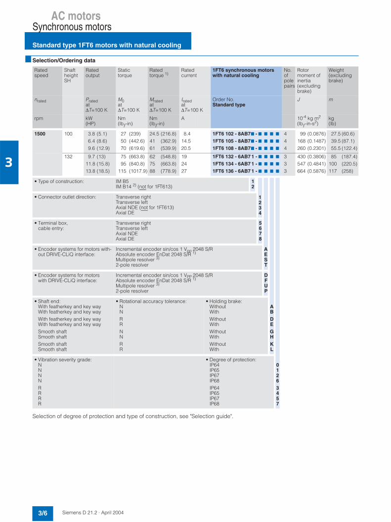
AC motorsSynchronous motors
Standard type 1FT6 motors with natural cooling
3/6 Siemens D 21.2 · April 2004
3
Selection/Ordering data
Selection of degree of protection and type of construction, see "Selection guide".
Ratedspeed
ShaftheightSH
Ratedoutput
Statictorque
Ratedtorque 1)
Ratedcurrent
1FT6 synchronous motorswith natural cooling
No.ofpolepairs
Rotormoment of inertia (excludingbrake)
Weight (excludingbrake)
nrated Pratedat∆T=100 K
M0at∆T=100 K
Mratedat∆T=100 K
Iratedat∆T=100 K
Order No.Standard type
J m
rpm kW(HP)
Nm(lbƒ-in)
Nm(lbƒ-in)
A 10-4 kg m2
(lbƒ-in-s2)kg(lb)
1500 100 3.8 (5.1)6.4 (8.6)9.6 (12.9)
27 (239)50 (442.6)70 (619.6)
24.5 (216.8)41 (362.9)61 (539.9)
8.414.520.5
1FT6 102 - 8AB77 - 7 7 7 7
1FT6 105 - 8AB77 - 7 7 7 7
1FT6 108 - 8AB77 - 7 7 7 7
444
99 (0.0876)168 (0.1487)260 (0.2301)
27.5 (60.6)39.5 (87.1)55.5 (122.4)
132 9.7 (13)11.8 (15.8)13.8 (18.5)
75 (663.8)95 (840.8)
115 (1017.9)
62 (548.8)75 (663.8)88 (778.9)
192427
1FT6 132 - 6AB7 1 - 7 7 7 7
1FT6 134 - 6AB7 1 - 7 7 7 7
1FT6 136 - 6AB7 1 - 7 7 7 7
333
430 (0.3806)547 (0.4841)664 (0.5876)
85 (187.4)100 (220.5)117 (258)
• Type of construction: IM B5IM B14 2) (not for 1FT613)
12
• Connector outlet direction: Transverse rightTransverse leftAxial NDE (not for 1FT613)Axial DE
• Terminal box, cable entry:
Transverse rightTransverse leftAxial NDEAxial DE
5678
• Encoder systems for motors with-out DRIVE-CLiQ interface:
Incremental encoder sin/cos 1 Vpp 2048 S/RAbsolute encoder EnDat 2048 S/R 1)
Multipole resolver 3)
2-pole resolver
• Encoder systems for motors with DRIVE-CLiQ interface:
Incremental encoder sin/cos 1 VPP 2048 S/RAbsolute encoder EnDat 2048 S/R 1)
Multipole resolver 3)
2-pole resolver
DFUP
• Shaft end:With featherkey and key wayWith featherkey and key wayWith featherkey and key wayWith featherkey and key waySmooth shaftSmooth shaftSmooth shaftSmooth shaft
• Rotational accuracy tolerance:NNRRNNRR
• Holding brake:WithoutWithWithoutWithWithoutWithWithoutWith
• Vibration severity grade:NNNNRRRR
• Degree of protection:IP64IP65IP67IP68IP64IP65IP67IP68
1234
AEST
ABDEGHKL
01263457

AC motorsSynchronous motors
Standard type 1FT6 motors with natural cooling
3/7Siemens D 21.2 · April 2004
3
Selection/Ordering data
1) If the absolute encoder is used, Mrated is reduced by 10%.2) Same flange as type IM B5 but with metric thread inserts in the four mounting holes.3) A max. operating frequency of 470 Hz must be observed with SINAMICS S.4) The current carrying capacity of the power cables corresponds to IEC 60204-1 for type of routing C under continuous operating conditions
with an ambient air temperature of +40 °C (+104 °F), designed for I0 (100 K), PVC/PUR-insulated cable.
Motor type(continued)
Staticcurrent
Calculated powerPcalc =M0 x nrated/9550
SINAMICS Motor ModuleRated output current
Power cable with complete shieldMotor connection (and brake connection) via power connector
I0at M0∆T=100 K
Pcalcfor M0∆T=100 K
Iratedat M0∆T=100 K
Order No. Power con-nector
Motorcablecross-sec-tion 4)
Order No.Pre-assembled cable
A kW(HP)
A Size mm2
1FT6 102 - 8AB7...1FT6 105 - 8AB7...1FT6 108 - 8AB7...
8.71622.3
4.2 (5.6)7.9 (10.6)
11.0 (14.7)
91830
6SL3 120 - 7TE21 - 0AA0- 7TE21 - 8AA0- 1TE23 - 0AA0
1.51.51.5
4 x 1.54 x 2.54 x 4
6FX7 002 - 57S21 - 7 7 70- 57S31 - 7 7 70- 57S41 - 7 7 70
1FT6 132 - 6AB7 ...1FT6 134 - 6AB7 ...1FT6 136 - 6AB7...
21.62734
11.8 (15.8)14.9 (20)18.1 (24.3)
303045
6SL3 120 - 1TE23 - 0AA0- 1TE23 - 0AA0- 1TE24 - 5AA0
1.51.51.5
4 x 44 x 44 x 10
6FX7 002 - 57S41 - 7 7 70- 57S41 - 7 7 70- 57S64 - 7 7 70
• Single Motor Module• Double Motor Module
12
Type of power cable
• MOTION-CONNECT 800• MOTION-CONNECT 500
• Without brake conductors• With brake conductors
See "MOTION-CONNECT connection system" for length code as well as power and signal cables.
85
CD
. ..
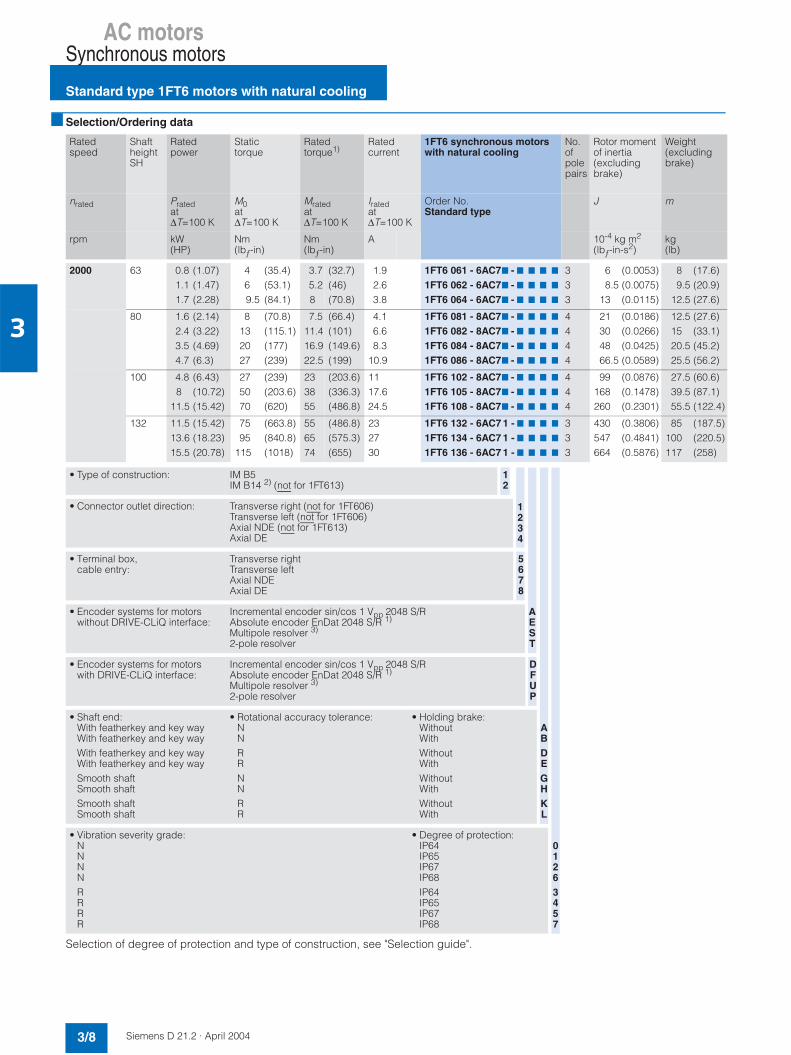
AC motorsSynchronous motors
Standard type 1FT6 motors with natural cooling
3/8 Siemens D 21.2 · April 2004
3
Selection/Ordering data
Selection of degree of protection and type of construction, see "Selection guide".
Ratedspeed
ShaftheightSH
Ratedpower
Statictorque
Ratedtorque1)
Ratedcurrent
1FT6 synchronous motorswith natural cooling
No.ofpolepairs
Rotor moment of inertia(excludingbrake)
Weight (excludingbrake)
nrated Pratedat∆T=100 K
M0at∆T=100 K
Mratedat∆T=100 K
Iratedat∆T=100 K
Order No.Standard type
J m
rpm kW(HP)
Nm(lbƒ-in)
Nm(lbƒ-in)
A 10-4 kg m2
(lbƒ-in-s2)kg(lb)
2000 63 0.8 (1.07)1.1 (1.47)1.7 (2.28)
469.5
(35.4)(53.1)(84.1)
3.75.28
(32.7)(46)(70.8)
1.92.63.8
1FT6 061 - 6AC77 - 7 7 7 7
1FT6 062 - 6AC77 - 7 7 7 7
1FT6 064 - 6AC77 - 7 7 7 7
333
6 (0.0053)8.5 (0.0075)
13 (0.0115)
8 (17.6)9.5 (20.9)
12.5 (27.6)
80 1.6 (2.14)2.4 (3.22)3.5 (4.69)4.7 (6.3)
8132027
(70.8)(115.1)(177)(239)
7.511.416.922.5
(66.4)(101)(149.6)(199)
4.16.68.3
10.9
1FT6 081 - 8AC77 - 7 7 7 7
1FT6 082 - 8AC77 - 7 7 7 7
1FT6 084 - 8AC77 - 7 7 7 7
1FT6 086 - 8AC77 - 7 7 7 7
4444
21 (0.0186)30 (0.0266)48 (0.0425)66.5 (0.0589)
12.5 (27.6)15 (33.1)20.5 (45.2)25.5 (56.2)
100 4.8 (6.43)8 (10.72)
11.5 (15.42)
275070
(239)(203.6)(620)
233855
(203.6)(336.3)(486.8)
1117.624.5
1FT6 102 - 8AC77 - 7 7 7 7
1FT6 105 - 8AC77 - 7 7 7 7
1FT6 108 - 8AC77 - 7 7 7 7
444
99 (0.0876)168 (0.1478)260 (0.2301)
27.5 (60.6)39.5 (87.1)55.5 (122.4)
132 11.5 (15.42)13.6 (18.23)15.5 (20.78)
7595
115
(663.8)(840.8)(1018)
556574
(486.8)(575.3)(655)
232730
1FT6 132 - 6AC7 1 - 7 7 7 7
1FT6 134 - 6AC7 1 - 7 7 7 7
1FT6 136 - 6AC7 1 - 7 7 7 7
333
430 (0.3806)547 (0.4841)664 (0.5876)
85 (187.5)100 (220.5)117 (258)
• Type of construction: IM B5IM B14 2) (not for 1FT613)
12
• Connector outlet direction: Transverse right (not for 1FT606)Transverse left (not for 1FT606)Axial NDE (not for 1FT613)Axial DE
• Terminal box, cable entry:
Transverse rightTransverse leftAxial NDEAxial DE
5678
• Encoder systems for motors without DRIVE-CLiQ interface:
Incremental encoder sin/cos 1 Vpp 2048 S/RAbsolute encoder EnDat 2048 S/R 1)
Multipole resolver 3)
2-pole resolver
• Encoder systems for motors with DRIVE-CLiQ interface:
Incremental encoder sin/cos 1 Vpp 2048 S/RAbsolute encoder EnDat 2048 S/R 1)
Multipole resolver 3)
2-pole resolver
DFUP
• Shaft end:With featherkey and key wayWith featherkey and key wayWith featherkey and key wayWith featherkey and key waySmooth shaftSmooth shaftSmooth shaftSmooth shaft
• Rotational accuracy tolerance:NNRRNNRR
• Holding brake:WithoutWithWithoutWithWithoutWithWithoutWith
• Vibration severity grade:NNNNRRRR
• Degree of protection:IP64IP65IP67IP68IP64IP65IP67IP68
1234
AEST
ABDEGHKL
01263457
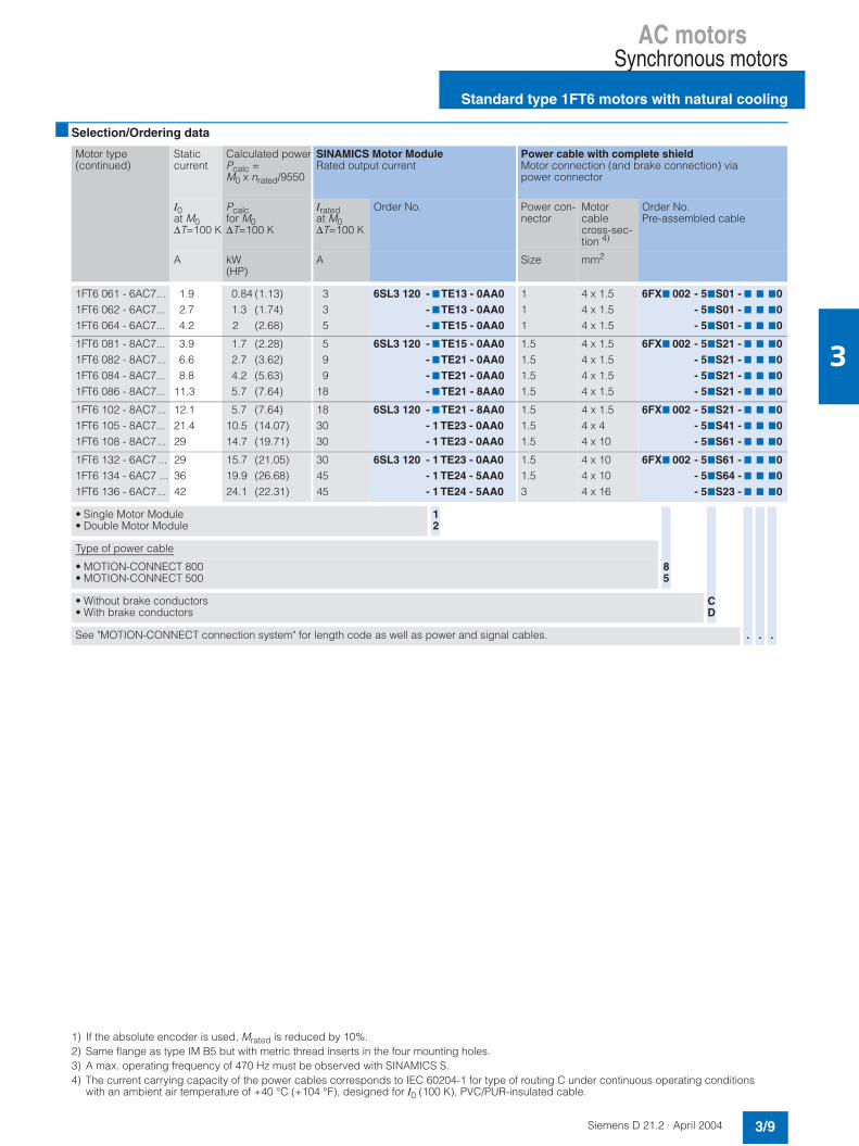
AC motorsSynchronous motors
Standard type 1FT6 motors with natural cooling
3/9Siemens D 21.2 · April 2004
3
Selection/Ordering data
1) If the absolute encoder is used, Mrated is reduced by 10%.2) Same flange as type IM B5 but with metric thread inserts in the four mounting holes.3) A max. operating frequency of 470 Hz must be observed with SINAMICS S.4) The current carrying capacity of the power cables corresponds to IEC 60204-1 for type of routing C under continuous operating conditions
with an ambient air temperature of +40 °C (+104 °F), designed for I0 (100 K), PVC/PUR-insulated cable.
Motor type(continued)
Staticcurrent
Calculated powerPcalc =M0 x nrated/9550
SINAMICS Motor ModuleRated output current
Power cable with complete shieldMotor connection (and brake connection) via power connector
I0at M0∆T=100 K
Pcalcfor M0∆T=100 K
Iratedat M0∆T=100 K
Order No. Power con-nector
Motorcablecross-sec-tion 4)
Order No.Pre-assembled cable
A kW(HP)
A Size mm2
1FT6 061 - 6AC7...1FT6 062 - 6AC7...1FT6 064 - 6AC7...
1.92.74.2
0.84 (1.13)1.3 (1.74)2 (2.68)
335
6SL3 120 - 7TE13 - 0AA0- 7TE13 - 0AA0- 7TE15 - 0AA0
111
4 x 1.54 x 1.54 x 1.5
6FX7 002 - 57S01 - 7 7 70- 57S01 - 7 7 70- 57S01 - 7 7 70
1FT6 081 - 8AC7...1FT6 082 - 8AC7...1FT6 084 - 8AC7...1FT6 086 - 8AC7...
3.96.68.8
11.3
1.7 (2.28)2.7 (3.62)4.2 (5.63)5.7 (7.64)
59
918
6SL3 120 - 7TE15 - 0AA0- 7TE21 - 0AA0- 7TE21 - 0AA0- 7TE21 - 8AA0
1.51.51.51.5
4 x 1.54 x 1.54 x 1.54 x 1.5
6FX7 002 - 57S21 - 7 7 70- 57S21 - 7 7 70- 57S21 - 7 7 70- 57S21 - 7 7 70
1FT6 102 - 8AC7...1FT6 105 - 8AC7...1FT6 108 - 8AC7...
12.121.429
5.7 (7.64)10.5 (14.07)14.7 (19.71)
183030
6SL3 120 - 7TE21 - 8AA0- 1 TE23 - 0AA0- 1 TE23 - 0AA0
1.51.51.5
4 x 1.54 x 44 x 10
6FX7 002 - 57S21 - 7 7 70- 57S41 - 7 7 70- 57S61 - 7 7 70
1FT6 132 - 6AC7 ...1FT6 134 - 6AC7 ...1FT6 136 - 6AC7...
293642
15.7 (21.05)19.9 (26.68)24.1 (22.31)
304545
6SL3 120 - 1 TE23 - 0AA0- 1 TE24 - 5AA0- 1 TE24 - 5AA0
1.51.53
4 x 104 x 104 x 16
6FX7 002 - 57S61 - 7 7 70- 57S64 - 7 7 70- 57S23 - 7 7 70
• Single Motor Module• Double Motor Module
12
Type of power cable
• MOTION-CONNECT 800• MOTION-CONNECT 500
• Without brake conductors• With brake conductors
See "MOTION-CONNECT connection system" for length code as well as power and signal cables.
85
CD
. ..

AC motorsSynchronous motors
Standard type 1FT6 motors with natural cooling
3/10 Siemens D 21.2 · April 2004
3
Selection/Ordering data
Selection of degree of protection and type of construction, see "Selection guide".
Ratedspeed
ShaftheightSH
Ratedpower
Statictorque
Ratedtorque 1)
Ratedcurrent
1FT6 synchronous motorswith natural cooling
No.ofpolepairs
Rotormoment of inertia (excludingbrake)
Weight (excludingbrake)
nrated Pratedat∆T=100 K
M0at∆T=100 K
Mratedat∆T=100 K
Iratedat∆T=100 K
Order No.Standard type
J m
rpm kW(HP)
Nm(lbƒ-in)
Nm(lbƒ-in)
A 10-4 kg m2
(lbƒ-in-s2)kg(lb)
3000 48 0.7 (0.99)1.4 (1.88)
2.65
(23)(44.3)
2.154.3
(19)(38.1)
1.72.9
1FT6 041 - 4AF71 - 7 7 7 7
1FT6 044 - 4AF71 - 7 7 7 7
22
2.9(0.0025)5.1(0.0045)
6.6 (14.6)8.3 (18.3)
63 1.1 (1.47)1.5 (2.01)2.2 (2.95)
469.5
(35.4)(53.1)(84.1)
3.54.77
(31)(41.6)(62)
2.63.44.9
1FT6 061 - 6AF77 - 7 7 7 7
1FT6 062 - 6AF77 - 7 7 7 7
1FT6 064 - 6AF77 - 7 7 7 7
333
6 (0.0053)8.5(0.0075)
13 (0.0115)
8 (17.6)9.5 (20.9)
12.5 (27.6)
80 2.2 (2.95)3.2 (4.29)4.6 (6.17)5.8 (7.77)
8132027
(70.8)(115.1)(177)(239)
6.910.314.718.5
(61.1)(91.2)(130.1)(163.7)
5.68.71113
1FT6 081 - 8AF77 - 7 7 7 7
1FT6 082 - 8AF77 - 7 7 7 7
1FT6 084 - 8AF77 - 7 7 7 7
1FT6 086 - 8AF77 - 7 7 7 7
4444
21 (0.0186)30 (0.0266)48 (0.0425)66.5(0.0589)
12.5 (27.6)15 (33.1)20.5 (45.2)25.5 (56.2)
100 6.1 (8.18)9.7 (13)
11.6 (15.55)
275070
(239)(442.6)(619.6)
19.53137
(172.6)(274.4)(327.5)
13.222.525
1FT6 102 - 8AF77 - 7 7 7 7
1FT6 105 - 8AF77 - 7 7 7 7
1FT6 108 - 8AF77 - 7 7 7 7
444
99 (0.0876)168 (0.1487)260 (0.2301)
27.5 (60.6)39.5 (87.1)55.5 (122.4)
132 11.3 (15.15) 75 (663.8) 36 (318.6) 23 1FT6 132 - 6AF71 - 7 7 7 7 3 430 (0.3806) 85 (187.4)
• Type of construction: IM B5IM B14 2) (not for 1FT604, 1FT613)
12
• Connector outlet direction: Transverse right (not for 1FT604, 1FT606)Transverse left (not for 1FT604, 1FT606)Axial NDE (not for 1FT613)Axial DE
• Terminal box, cable entry:
Transverse rightTransverse leftAxial NDEAxial DE
5678
• Encoder systems for motors without DRIVE-CLiQ interface:
Incremental encoder sin/cos 1 Vpp 2048 S/RAbsolute encoder EnDat 2048 S/R 1)
Multipole resolver 3)
2-pole resolver
• Encoder systems for motors with DRIVE-CLiQ interface:
Incremental encoder sin/cos 1 Vpp 2048 S/RAbsolute encoder EnDat 2048 S/R 1)
Multipole resolver 3)
2-pole resolver
DFUP
• Shaft end:With featherkey and key wayWith featherkey and key wayWith featherkey and key wayWith featherkey and key waySmooth shaftSmooth shaftSmooth shaftSmooth shaft
• Rotational accuracy tolerance:NNRRNNRR
• Holding brake:WithoutWithWithoutWithWithoutWithWithoutWith
• Vibration severity grade:NNNNRRRR
• Degree of protection:IP64IP65IP67IP68IP64IP65IP67IP68
1234
AEST
ABDEGHKL
01263457

AC motorsSynchronous motors
Standard type 1FT6 motors with natural cooling
3/11Siemens D 21.2 · April 2004
3
Selection/Ordering data
1) If the absolute encoder is used, Mrated is reduced by 10%.2) Same flange as type IM B5 but with metric thread inserts in the four mounting holes.3) A max. operating frequency of 470 Hz must be observed with SINAMICS S.4) With the specified motor module, the motor cannot be fully utilized to ∆T = 100 K winding temperature rise. If a motor module with a higher rating
is used, you must check whether the specified power cable can be connected to it.5) The current carrying capacity of the power cables corresponds to IEC 60204-1 for type of routing C under continuous operating conditions
with an ambient air temperature of +40 °C (+104 °F), designed for I0 (100 K), PVC/PUR-insulated cable.
Motor typecontinued
Staticcurrent
Calculated powerPcalc =M0 x nrated/9550
SINAMICS Motor ModuleRated output current
Power cable with complete shieldMotor connection (and brake connection) via power connector
I0at M0∆T=100 K
Pcalcfor M0∆T=100 K
Iratedat M0∆T=100 K
Order No. Power con-nector
Motorcablecross-sec-tion 5)
Order No.Pre-assembled cable
A kW(HP)
A Size mm2
1FT6 041 - 4AF7 ...1FT6 044 - 4AF7 ...
1.93
0.8 (1.1)1.6 (2.1)
33
6SL3 120 - 7TE13 - 0AA0- 7TE13 - 0AA0
11
4 x 1.54 x 1.5
6FX7 002 - 57S01 - 7 7 70- 57S01 - 7 7 70
1FT6 061 - 6AF7 ...1FT6 062 - 6AF7 ...1FT6 064 - 6AF7 ...
2.74.16.1
1.3 (1.7)1.9 (2.5)3 (4)
359
6SL3 120 - 7TE13 - 0AA0- 7TE15 - 0AA0- 7TE21 - 0AA0
111
4 x 1.54 x 1.54 x 1.5
6FX7 002 - 57S01 - 7 7 70- 57S01 - 7 7 70- 57S01 - 7 7 70
1FT6 081 - 8AF7 ...1FT6 082 - 8AF7 ...1FT6 084 - 8AF7 ...1FT6 086 - 8AF7 ...
5.89.6
13.216.4
2.5 (3.4)4.1 (5.5)6.3 (8.5)8.5 (11.4)
9181818
6SL3 120 - 7TE21 - 0AA0- 7TE21 - 8AA0- 7TE21 - 8AA0- 7TE21 - 8AA0
1.51.51.51.5
4 x 1.54 x 1.54 x 1.54 x 2.5
6FX7 002 - 57S21 - 7 7 70- 57S21 - 7 7 70- 57S21 - 7 7 70- 57S31 - 7 7 70
1FT6 102 - 8AF7 ...1FT6 105 - 8AF7 ...1FT6 108 - 8AF7 ...
16.93241
8.5 (11.4)15.7 (21)22 (29.5)
1830 4)
45
6SL3 120 - 7TE21 - 8AA0- 1 TE23 - 0AA0- 1 TE24 - 5AA0
1.51.53
4 x 2.54 x 104 x 16
6FX7 002 - 57S31 - 7 7 70- 57S61 - 7 7 70- 57S23 - 7 7 70
1FT6 132 - 6AF7 ... 43 23.6 (31.6) 45 6SL3 120 - 1 TE24 - 5AA0 3 4 x 16 6FX7 002 - 57S23 - 7 7 70
• Single Motor Module• Double Motor Module
12
Type of power cable
• MOTION-CONNECT 800• MOTION-CONNECT 500
• Without brake conductors• With brake conductors
See "MOTION-CONNECT connection system" for length code as well as power and signal cables.
85
CD
. ..

AC motorsSynchronous motors
Standard type 1FT6 motors with natural cooling
3/12 Siemens D 21.2 · April 2004
3
Selection/Ordering data
Selection of degree of protection and type of construction, see "Selection guide".
Ratedspeed
ShaftheightSH
Ratedpower
Statictorque
Ratedtorque 1)
Ratedcurrent
1FT6 synchronous motorswith natural cooling
No.ofpolepairs
Rotormoment of inertia (excludingbrake)
Weight (excluding brake)
nrated Pratedat∆T=100 K
M0at ∆T=100 K
Mratedat∆T=100 K
Iratedat∆T=100 K
Order No.Standard type
J m
rpm kW(HP)
Nm(lbƒ-in)
Nm(lbƒ-in)
A 10-4 kg m2
(lbƒ-in-s2)kg(lb)
4500 63 1.4 (1.88)1.7 (2.28)2.3 (3.08)
4 (35.4)6 (53.1)9.5 (84.1)
2.9 (25.7)3.6 (31.9)4.8 (42.5)
3.43.95.5
1FT6 061 - 6AH77 - 7 7 7 7
1FT6 062 - 6AH77 - 7 7 7 7
1FT6 064 - 6AH77 - 7 7 7 7
333
6 (0.0053)8.5 (0.0075)
13 (0.0115)
8 (17.6)9.5 (20.9)
12.5 (27.6)
80 2.7 (3.62)4 (5.36)4.9 (6.57)5.7 (7.64)
8 (70.8)13 (115.1)20 (177)27 (239)
5.8 (51.3)8.5 (75.2)
10.5 (92.9)12 (106.2)
7.31112.512.6
1FT6 081 - 8AH77 - 7 7 7 7
1FT6 082 - 8AH77 - 7 7 7 7
1FT6 084 - 8AH77 - 7 7 7 7
1FT6 086 - 8AH77 - 7 7 7 7
4444
21 (0.0186)30 (0.0266)48 (0.0425)66.5 (0.0589)
12.5 (27.6)15 (33.1)20.5 (45.2)25.5 (56.2)
100 5.7 (7.64) 27 (239) 12 (106.2) 12 1FT6 102 - 8AH77 - 7 7 7 7 4 99 (0.0876) 27.5 (60.6)
• Type of construction: IM B5IM B14 2)
12
• Connector outlet direction: Transverse right (not for 1FT606)Transverse left (not for 1FT606)Axial NDEAxial DE
• Terminal box,cable entry(only on 1FT61):
Transverse rightTransverse leftAxial NDEAxial DE
5678
• Encoder systems for motors with-out DRIVE-CLiQ interface:
Incremental encoder sin/cos 1 Vpp 2048 S/RAbsolute encoder EnDat 2048 S/R 1)
Multipole resolver 3)
2-pole resolver
• Encoder systems for motors with DRIVE-CLiQ interface:
Incremental encoder sin/cos 1 Vpp 2048 S/RAbsolute encoder EnDat 2048 S/R 1)
Multipole resolver 3)
2-pole resolver
DFUP
• Shaft end:With featherkey and key wayWith featherkey and key wayWith featherkey and key wayWith featherkey and key waySmooth shaftSmooth shaftSmooth shaftSmooth shaft
• Rotational accuracy tolerance:NNRRNNRR
• Holding brake:WithoutWithWithoutWithWithoutWithWithoutWith
• Vibration severity grade:NNNNRRRR
• Degree of protection:IP64IP65IP67IP68IP64IP65IP67IP68
1234
AEST
ABDEGHKL
01263457
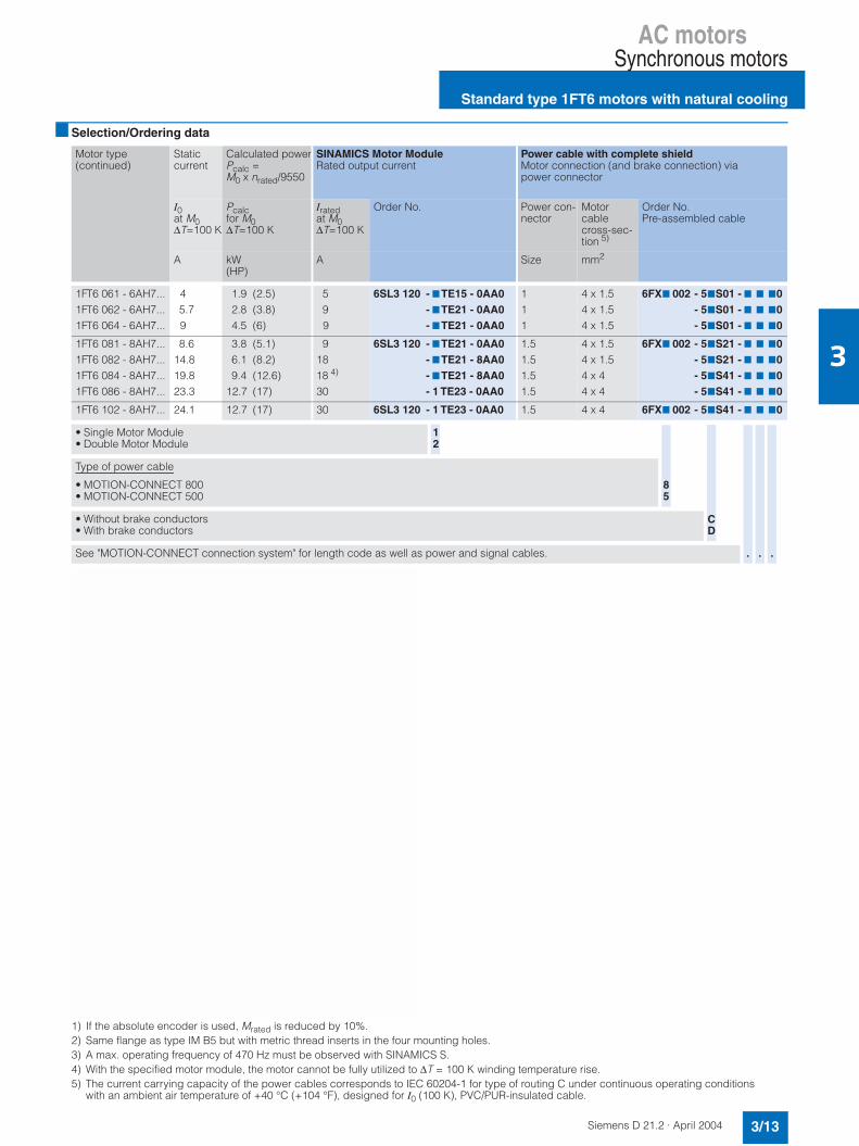
AC motorsSynchronous motors
Standard type 1FT6 motors with natural cooling
3/13Siemens D 21.2 · April 2004
3
Selection/Ordering data
1) If the absolute encoder is used, Mrated is reduced by 10%.2) Same flange as type IM B5 but with metric thread inserts in the four mounting holes.3) A max. operating frequency of 470 Hz must be observed with SINAMICS S.4) With the specified motor module, the motor cannot be fully utilized to ∆T = 100 K winding temperature rise.5) The current carrying capacity of the power cables corresponds to IEC 60204-1 for type of routing C under continuous operating conditions
with an ambient air temperature of +40 °C (+104 °F), designed for I0 (100 K), PVC/PUR-insulated cable.
Motor type(continued)
Staticcurrent
Calculated powerPcalc =M0 x nrated/9550
SINAMICS Motor ModuleRated output current
Power cable with complete shieldMotor connection (and brake connection) via power connector
I0at M0∆T=100 K
Pcalcfor M0∆T=100 K
Iratedat M0∆T=100 K
Order No. Power con-nector
Motorcablecross-sec-tion 5)
Order No.Pre-assembled cable
A kW(HP)
A Size mm2
1FT6 061 - 6AH7...1FT6 062 - 6AH7...1FT6 064 - 6AH7...
45.79
1.9 (2.5)2.8 (3.8)4.5 (6)
59
9
6SL3 120 - 7TE15 - 0AA0- 7TE21 - 0AA0- 7TE21 - 0AA0
111
4 x 1.54 x 1.54 x 1.5
6FX7 002 - 57S01 - 7 7 70- 57S01 - 7 7 70- 57S01 - 7 7 70
1FT6 081 - 8AH7...1FT6 082 - 8AH7...1FT6 084 - 8AH7...1FT6 086 - 8AH7...
8.614.819.823.3
3.8 (5.1)6.1 (8.2)9.4 (12.6)
12.7 (17)
91818 4)
30
6SL3 120 - 7TE21 - 0AA0- 7TE21 - 8AA0- 7TE21 - 8AA0- 1 TE23 - 0AA0
1.51.51.51.5
4 x 1.54 x 1.54 x 44 x 4
6FX7 002 - 57S21 - 7 7 70- 57S21 - 7 7 70- 57S41 - 7 7 70- 57S41 - 7 7 70
1FT6 102 - 8AH7... 24.1 12.7 (17) 30 6SL3 120 - 1 TE23 - 0AA0 1.5 4 x 4 6FX7 002 - 57S41 - 7 7 70
• Single Motor Module• Double Motor Module
12
Type of power cable
• MOTION-CONNECT 800• MOTION-CONNECT 500
• Without brake conductors• With brake conductors
See "MOTION-CONNECT connection system" for length code as well as power and signal cables.
85
CD
. ..

AC motorsSynchronous motors
Standard type 1FT6 motors with natural cooling
3/14 Siemens D 21.2 · April 2004
3
Selection/Ordering data
Selection of degree of protection and type of construction, see "Selection guide".
Ratedspeed
ShaftheightSH
Ratedpower
Statictorque
Ratedtorque 1)
Ratedcurrent
1FT6 synchronous motorswith natural cooling
No.ofpolepairs
Rotormoment of inertia(excluding brake)
Weight (excludingbrake)
nrated Pratedat∆T=100 K
M0at∆T=100 K
Mratedat∆T=100 K
Iratedat∆T=100 K
Order No.Standard type
J m
rpm kW(HP)
Nm(lbƒ-in)
Nm(lbƒ-in)
A 10-4 kg m2
(lbƒ-in-s2)kg(lb)
6000 28 0.19 (0.25)0.31 (0.42)
0.40.8
(3.5)(7.1)
0.30.5
(2.7)(4.4)
1.10.9
1FT6 021 - 6AK71 - 7 7 7 7
1FT6 024 - 6AK71 - 7 7 7 7
33
0.21 (0.0002)0.34 (0.0003)
1.2 (2.6)2.1 (4.6)
36 0.47 (0.63)0.88 (1.18)
12
(8.8)(17.7)
0.751.4
(6.6)(12.4)
1.22.1
1FT6 031 - 4AK71 - 7 7 7 7
1FT6 034 - 4AK71 - 7 7 7 7
22
0.65 (0.0006)1.1 (0.0010)
3.1 (6.8)4.4 (9.7)
48 1.1 (1.47)1.9 (2.55)
2.65
(23)(44.3)
1.73
(15)(26.6)
2.44.1
1FT6 041 - 4AK71 - 7 7 7 7
1FT6 044 - 4AK71 - 7 7 7 7
22
2.9 (0.0025)5.1 (0.0045)
6.6 (14.6)8.3 (18.3)
63 1.3 (1.74)1.3 (1.74)1.3 (1.74)
469.5
(35.4)(53.1)(84.1)
2.12.12.1
(18.6)(18.6)(18.6)
3.13.23.5
1FT6 061 - 6AK77 - 7 7 7 7
1FT6 062 - 6AK77 - 7 7 7 7
1FT6 064 - 6AK77 - 7 7 7 7
333
6 (0.0053)8.5 (0.0075)
13 (0.0115)
8 (17.6)9.5 (20.9)
12.5 (27.6)
80 2.9 (3.89)3.5 (4.69)4.1 (15.55)
81320
(70.8)(115.1)(177)
4.65.56.5
(40.7)(48.7)(57.5)
7.79.19.2
1FT6 081 - 8AK77 - 7 7 7 7
1FT6 082 - 8AK77 - 7 7 7 7
1FT6 084 - 8AK77 - 7 7 7 7
444
21 (0.0186)30 (0.0266)48 (0.0425)
12.5 (27.6)15 (33.1)20.5 (45.2)
• Type of construction: IM B5IM B14 2) (not for 1FT602, 1FT603, 1FT604)
12
• Connector outlet direction: Transverse right (not for 1FT603, 1FT604, 1FT606)Transverse left (not for 1FT603, 1FT604, 1FT606)Axial NDEAxial DE
• Encoder systems for motors without DRIVE-CLiQ interface:
Incremental encoder sin/cos 1 Vpp 2048 S/RAbsolute encoder EnDat 2048 S/R 1) (not for 1FT602)Absolute encoder EnDat 512 S/R 1) (not for 1FT602)Multipole resolver 3)
2-pole resolver
• Encoder systems for motors with DRIVE-CLiQ interface:
Incremental encoder sin/cos 1 Vpp 2048 S/RAbsolute encoder EnDat 2048 S/R 1) (not for 1FT602)Absolute encoder EnDat 512 S/R 1) (not for 1FT602)Multipole resolver 3)
2-pole resolver
DFLUP
• Shaft end:With featherkey and key wayWith featherkey and key wayWith featherkey and key wayWith featherkey and key waySmooth shaftSmooth shaftSmooth shaftSmooth shaft
• Rotational accuracy tolerance:NNRRNNRR
• Holding brake:WithoutWithWithoutWithWithoutWithWithoutWith
• Vibration severity grade:NN (not for 1FT602)NN (not for 1FT602)
• RR (not for 1FT602)RR (not for 1FT602)
• Degree of protection:IP64IP65 (not for 1FT602)IP67IP68 (not for 1FT602)IP64IP65 (not for 1FT602)IP67IP68 (not for 1FT602)
1234
AEHST
ABDEGHKL
01263457
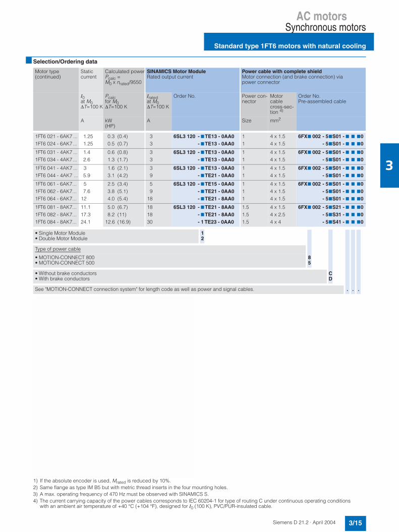
AC motorsSynchronous motors
Standard type 1FT6 motors with natural cooling
3/15Siemens D 21.2 · April 2004
3
Selection/Ordering data
1) If the absolute encoder is used, Mrated is reduced by 10%.2) Same flange as type IM B5 but with metric thread inserts in the four mounting holes.3) A max. operating frequency of 470 Hz must be observed with SINAMICS S.4) The current carrying capacity of the power cables corresponds to IEC 60204-1 for type of routing C under continuous operating conditions
with an ambient air temperature of +40 °C (+104 °F), designed for I0 (100 K), PVC/PUR-insulated cable.
Motor type(continued)
Staticcurrent
Calculated powerPcalc =M0 x nrated/9550
SINAMICS Motor ModuleRated output current
Power cable with complete shieldMotor connection (and brake connection) via power connector
I0at M0∆T=100 K
Pcalcfor M0∆T=100 K
Iratedat M0∆T=100 K
Order No. Power con-nector
Motorcablecross-sec-tion 4)
Order No.Pre-assembled cable
A kW(HP)
A Size mm2
1FT6 021 - 6AK7 ...1FT6 024 - 6AK7...
1.251.25
0.3 (0.4)0.5 (0.7)
33
6SL3 120 - 7TE13 - 0AA0- 7TE13 - 0AA0
11
4 x 1.54 x 1.5
6FX7 002 - 57S01 - 7 7 70- 57S01 - 7 7 70
1FT6 031 - 4AK7 ...1FT6 034 - 4AK7...
1.42.6
0.6 (0.8)1.3 (1.7)
33
6SL3 120 - 7TE13 - 0AA0- 7TE13 - 0AA0
11
4 x 1.54 x 1.5
6FX7 002 - 57S01 - 7 7 70- 57S01 - 7 7 70
1FT6 041 - 4AK7 ...1FT6 044 - 4AK7 ...
35.9
1.6 (2.1)3.1 (4.2)
39
6SL3 120 - 7TE13 - 0AA0- 7TE21 - 0AA0
11
4 x 1.54 x 1.5
6FX7 002 - 57S01 - 7 7 70- 57S01 - 7 7 70
1FT6 061 - 6AK7...1FT6 062 - 6AK7...1FT6 064 - 6AK7...
57.6
12
2.5 (3.4)3.8 (5.1)4.0 (5.4)
59
18
6SL3 120 - 7TE15 - 0AA0- 7TE21 - 0AA0- 7TE21 - 8AA0
111
4 x 1.54 x 1.54 x 1.5
6FX7 002 - 57S01 - 7 7 70- 57S01 - 7 7 70- 57S01 - 7 7 70
1FT6 081 - 8AK7...1FT6 082 - 8AK7...1FT6 084 - 8AK7...
11.117.324.1
5.0 (6.7)8.2 (11)
12.6 (16.9)
181830
6SL3 120 - 7TE21 - 8AA0- 7TE21 - 8AA0- 1 TE23 - 0AA0
1.51.51.5
4 x 1.54 x 2.54 x 4
6FX7 002 - 57S21 - 7 7 70- 57S31 - 7 7 70- 57S41 - 7 7 70
• Single Motor Module• Double Motor Module
12
Type of power cable
• MOTION-CONNECT 800• MOTION-CONNECT 500
• Without brake conductors• With brake conductors
See "MOTION-CONNECT connection system" for length code as well as power and signal cables.
85
CD
. ..

AC motorsSynchronous motors
Standard type 1FT6 motors with forced ventilation
3/16 Siemens D 21.2 · April 2004
3
Selection/Ordering data
Selection of degree of protection and type of construction, see "Selection guides".
Ratedspeed
ShaftheightSH
Ratedpower
Statictorque
Ratedtorque 1)
Ratedcurrent
1FT6 synchronous motorsForced ventilation2)
No.ofpolepairs
Rotormoment of inertia (excludingbrake)
Weight (excludingbrake)
nrated Pratedat∆T=100 K
M0at∆T=100 K
Mratedat∆T=100 K
Iratedat∆T=100 K
Order No.Standard type
J m
rpm kW(HP)
Nm(lbƒ-in)
Nm(lbƒ-in)
A 10-4 kg m2
(lbƒ-in-s2)kg(lb)
1500 100 9.3 (12.47)13 (17.43)
65 (575.3)90 (796.6)
59 (522.2)83 (734.6)
21.731
1FT6 105 - 8SB77 - 7 7 7 7
1FT6 108 - 8SB77 - 7 7 7 7
44
168 (0.1487)260 (0.2301)
45.5 (100.3)61.5 (135.6)
132 16 (21.45)20.4 (27.35)25.1 (33.65)
110 (973.6)140 (1239.1)175 (1548.9)
102 (902.8)130 (1150.6)160 (1416.2)
364555
1FT6 132 - 6SB71 - 7 7 7 7
1FT6 134 - 6SB71 - 7 7 7 7
1FT6 136 - 6SB71 - 7 7 7 7
333
430 (0.3806)547 (0.4810)664 (0.5876)
91 (200.6)106 (233.7)123 (271.2)
2000 100 11.7 (15.68)16.8 (22.52)
65 (575.3)90 (796.6)
56 (495.6)80 (708.1)
2840
1FT6 105 - 8SC77 - 7 7 7 7
1FT6 108 - 8SC77 - 7 7 7 7
44
168 (0.1487)260 (0.2301)
45.5 (100.3)61.5 (135.6)
132 20.5 (27.48)26.2 (35.12)32.5 (43.56)
110 (973.6)140 (1239.1)175 (1548.9)
98 (867.4)125 (1106.4)155 (1371.9)
465772
1FT6 132 - 6SC71 - 7 7 7 7
1FT6 134 - 6SC71 - 7 7 7 7
1FT6 136 - 6SC71 - 7 7 7 7
333
430 (0.3806)547 (0.4810)664 (0.5876)
91 (200.6)106 (233.7)123 (271.2)
• Type of construction: IM B5IM B14 3)
12
• Connector outlet direction: Transverse rightTransverse leftAxial NDE (not for 1FT613)Axial DE
• Terminal box, cable entry:
Transverse rightTransverse leftAxial NDEAxial DE
5678
• Encoder systems for motors without DRIVE-CLiQ interface:
Incremental encoder sin/cos 1 Vpp 2048 S/RAbsolute encoder EnDat 2048 S/R 1)
Multipole resolver 4)
2-pole resolver
• Encoder systems for motors with DRIVE-CLiQ interface:
Incremental encoder sin/cos 1 Vpp 2048 S/RAbsolute encoder EnDat 2048 S/R 1)
Multipole resolver 4)
2-pole resolver
DFUP
• Shaft end:With featherkey and key wayWith featherkey and key wayWith featherkey and key wayWith featherkey and key waySmooth shaftSmooth shaftSmooth shaftSmooth shaft
• Rotational accuracy tolerance:NNRRNNRR
• Holding brake:WithoutWithWithoutWithWithoutWithWithoutWith
• Vibration severity grade:NNRR
• Degree of protection: 5)
IP64IP65IP64IP65
1234
AEST
ABDEGHKL
0134
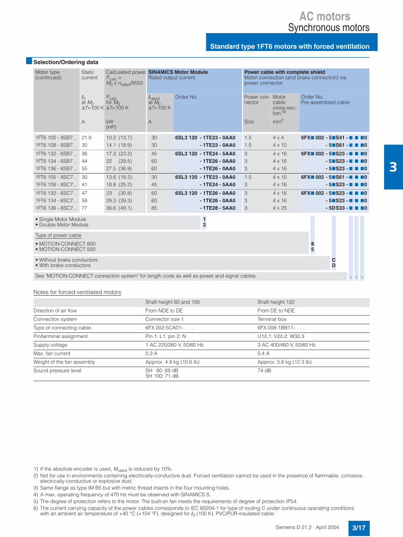
AC motorsSynchronous motors
Standard type 1FT6 motors with forced ventilation
3/17Siemens D 21.2 · April 2004
3
Selection/Ordering data
Notes for forced-ventilated motors
1) If the absolute encoder is used, Mrated is reduced by 10%.2) Not for use in environments containing electrically-conductive dust. Forced ventilation cannot be used in the presence of flammable, corrosive,
electrically-conductive or explosive dust.3) Same flange as type IM B5 but with metric thread inserts in the four mounting holes.4) A max. operating frequency of 470 Hz must be observed with SINAMICS S.5) The degree of protection refers to the motor. The built-on fan meets the requirements of degree of protection IP54.6) The current carrying capacity of the power cables corresponds to IEC 60204-1 for type of routing C under continuous operating conditions
with an ambient air temperature of +40 °C (+104 °F), designed for I0 (100 K), PVC/PUR-insulated cable.
Motor type(continued)
Staticcurrent
Calculated powerPcalc =M0 x nrated/9550
SINAMICS Motor ModuleRated output current
Power cable with complete shieldMotor connection (and brake connection) via power connector
I0at M0∆T=100 K
Pcalcfor M0∆T=100 K
Iratedat M0∆T=100 K
Order No. Power con-nector
Motorcablecross-sec-tion 6)
Order No.Pre-assembled cable
A kW(HP)
A Size mm2
1FT6 105 - 8SB7...1FT6 108 - 8SB7...
21.930
10.2 (13.7)14.1 (18.9)
3030
6SL3 120 - 1TE23 - 0AA0- 1TE23 - 0AA0
1.51.5
4 x 44 x 10
6FX7 002 - 57S41 - 7 7 70- 57S61 - 7 7 70
1FT6 132 - 6SB7...1FT6 134 - 6SB7...1FT6 136 - 6SB7...
364455
17.3 (23.2)22 (29.5)27.5 (36.9)
456060
6SL3 120 - 1TE24 - 5AA0- 1TE26 - 0AA0- 1TE26 - 0AA0
333
4 x 164 x 164 x 16
6FX7 002 - 57S23 - 7 7 70- 57S23 - 7 7 70- 57S23 - 7 7 70
1FT6 105 - 8SC7...1FT6 108 - 8SC7...
3041
13.6 (18.2)18.8 (25.2)
3045
6SL3 120 - 1TE23 - 0AA0- 1TE24 - 5AA0
1.53
4 x 104 x 16
6FX7 002 - 57S61 - 7 7 70- 57S23 - 7 7 70
1FT6 132 - 6SC7...1FT6 134 - 6SC7...1FT6 136 - 6SC7...
475877
23 (30.8)29.3 (39.3)36.6 (49.1)
606085
6SL3 120 - 1TE26 - 0AA0- 1TE26 - 0AA0- 1TE28 - 5AA0
333
4 x 164 x 164 x 25
6FX7 002 - 57S23 - 7 7 70- 57S23 - 7 7 70- 5DS33 - 7 7 70
• Single Motor Module• Double Motor Module
12
Type of power cable
• MOTION-CONNECT 800• MOTION-CONNECT 500
• Without brake conductors• With brake conductors
See "MOTION-CONNECT connection system" for length code as well as power and signal cables.
Shaft height 80 and 100 Shaft height 132
Direction of air flow From NDE to DE From DE to NDE
Connection system Connector size 1 Terminal box
Type of connecting cable 6FX.002-5CA01-. . . . 6FX.008-1BB11-. . . .
Pin/terminal assignment Pin 1: L1, pin 2: N U1/L1: V2/L2: W3/L3
Supply voltage 1 AC 220/260 V, 50/60 Hz 3 AC 400/460 V, 50/60 Hz
Max. fan current 0.3 A 0.4 A
Weight of the fan assembly Approx. 4.8 kg (10.6 lb) Approx. 5.6 kg (12.3 lb)
Sound pressure level SH 80: 69 dB SH 100: 71 dB
74 dB
85
CD
. ..
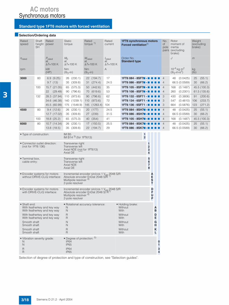
AC motorsSynchronous motors
Standard type 1FT6 motors with forced ventilation
3/18 Siemens D 21.2 · April 2004
3
Selection/Ordering data
Selection of degree of protection and type of construction, see "Selection guides".
Ratedspeed
ShaftheightSH
Ratedpower
Statictorque
Ratedtorque 1)
Ratedcurrent
1FT6 synchronous motorsForced ventilation2)
No.ofpolepairs
Rotormoment of inertia(excluding brake)
Weight (excluding brake)
nrated Pratedat∆T=100 K
M0at∆T=100 K
Mratedat∆T=100 K
Iratedat∆T=100 K
Order No.Standard type
J m
rpm kW(HP)
Nm(lbƒ-in)
Nm(lbƒ-in)
A 10-4 kg m2
(lbƒ-in-s2)kg(lb)
3000 80 6.9 (9.25)9.7 (13)
26 (230.1)35 (309.8)
22 (194.7)31 (274.4)
1724.5
1FT6 084 - 8SF77 - 7 7 7 7
1FT6 086 - 8SF77 - 7 7 7 7
44
48 (0.0425)66.5 (0.0589)
25 (55.1)30 (66.2)
100 15.7 (21.05)22 (29.49)
65 (575.3)90 (796.6)
50 (442.6)70 (619.6)
3553
1FT6 105 - 8SF77 - 7 7 7 7
1FT6 108 - 8SF77 - 7 7 7 7
44
168 (0.1487)260 (0.2301)
45.5 (100.3)61.5 (135.6)
132 28.3 (37.94)34.6 (46.38)45.5 (60.99)
110 (973.6)140 (1239.1)175 (1548.9)
90 (796.6)110 (973.6)145 (1283.4)
6272
104
1FT6 132 - 6SF71 - 7 7 7 7
1FT6 134 - 6SF71 - 7 7 7 7
1FT6 136 - 6SF71 - 7 7 7 7
333
430 (0.3806)547 (0.4810)664 (0.5876)
91 (200.6)106 (233.7)123 (271.2)
4500 80 9.4 (12.6)12.7 (17.02)
26 (230.1)35 (309.8)
20 (177)27 (239)
24.531.5
1FT6 084 - 8SH77 -7 7 7 7
1FT6 086 - 8SH77 -7 7 7 7
44
48 (0.0425)66.5 (0.0589)
25 (55.1)30 (66.2)
100 18.8 (25.2) 65 (575.3) 40 (354) 41 1FT6 105 - 8SH77 -7 7 7 7 4 168 (0.1487) 45.5 (100.3)
6000 80 10.7 (14.34)13.8 (18.5)
26 (230.1)35 (309.8)
17 (150.5)22 (194.7)
25.529
1FT6 084 - 8SK77 -7 7 7 7
1FT6 086 - 8SK77 -7 7 7 7
44
48 (0.0425)66.5 (0.0589)
25 (55.1)30 (66.2)
• Type of construction: IM B5IM B14 3) (for 1FT613)
12
• Connector outlet direction:(not for 1FT6 136)
Transverse rightTransverse leftAxial NDE (not for 1FT613)Axial DE
• Terminal box, cable entry:
Transverse rightTransverse leftAxial NDEAxial DE
5678
• Encoder systems for motors without DRIVE-CLiQ interface:
Incremental encoder sin/cos 1 Vpp 2048 S/RAbsolute encoder EnDat 2048 S/R 1)
Multipole resolver 4)
2-pole resolver
• Encoder systems for motors with DRIVE-CLiQ interface:
Incremental encoder sin/cos 1 Vpp 2048 S/RAbsolute encoder EnDat 2048 S/ R1)
Multipole resolver 4)
2-pole resolver
DFUP
• Shaft end:With featherkey and key wayWith featherkey and key wayWith featherkey and key wayWith featherkey and key waySmooth shaftSmooth shaftSmooth shaftSmooth shaft
• Rotational accuracy tolerance:NNRRNNRR
• Holding brake:WithoutWithWithoutWithWithoutWithWithoutWith
• Vibration severity grade:NNRR
• Degree of protection: 5)
IP64IP65IP64IP65
1234
AEST
ABDEGHKL
0134

AC motorsSynchronous motors
Standard type 1FT6 motors with forced ventilation
3/19Siemens D 21.2 · April 2004
3
Selection/Ordering data
Notes for forced-ventilated motors
1) If the absolute encoder is used, Mrated is reduced by 10%.2) Not for use in environments containing electrically-conductive dust. Forced ventilation cannot be used in the presence of flammable, corrosive,
electrically-conductive or explosive dust.3) Same flange as type IM B5 but with metric thread inserts in the four mounting holes.4) A max. operating frequency of 470 Hz must be observed with SINAMICS. 5) The degree of protection refers to the motor. The built-on fan meets the requirements of degree of protection IP54.6) With the specified motor module, the motor cannot be fully utilized to ∆T = 100 K winding temperature rise.7) The current carrying capacity of the power cables corresponds to IEC 60204-1 for type of routing C under continuous operating conditions
with an ambient air temperature of +40 °C (+104 °F), designed for I0 (100 K), PVC/PUR-insulated cable.
Motor type(continued)
Staticcurrent
Calculated powerPcalc =M0 x nrated/9550
SINAMICS Motor ModuleRated output current
Power cable with complete shieldMotor connection (and brake connection) via power connector
I0at M0∆T=100 K
Pcalcfor M0∆T=100 K
Iratedat M0∆T=100 K
Order No. Power con-nector
Motorcablecross-sec-tion 7)
Order No.Pre-assembled cable
A kW(HP)
A Size mm2
1FT6 084 - 8SF7...1FT6 086 - 8SF7...
18.225
8.2 (11)11 (14.7)
18 6)
306SL3 120 - 7TE21 - 8AA0
- 1TE23 - 0AA01.51.5
4 x 2.54 x 4
6FX7 002 - 57S31 - 7 7 70- 57S41 - 7 7 70
1FT6 105 - 8SF7...1FT6 108 - 8SF7...
4262
20.4 (27.3)28.3 (37.9)
45 60 6)
6SL3 120 - 1TE24 - 5AA0- 1TE26 - 0AA0
33
4 x 164 x 16
6FX7 002 - 57S23 - 7 7 70- 57S23 - 7 7 70
1FT6 132 - 6SF7...1FT6 134 - 6SF7...1FT6 136 - 6SF7...
6983
110
34.6 (46.4)44 (59)55 (73.7)
8585
132
6SL3 120 - 1TE28 - 5AA0- 1TE28 - 5AA0- 1TE31 - 5AA0
33
4 x 254 x 35
6FX7 002 - 5DS33 - 7 7 70- 5DS43 - 7 7 70
1FT6 084 - 8SH7...1FT6 086 - 8SH7...
2638
12.3 (16.5)16.5 (22.2)
3045
6SL3 120 - 1TE23 - 0AA0- 1TE24 - 5AA0
1.53
4 x 44 x 16
6FX7 002 - 57S41 - 7 7 70- 57S23 - 7 7 70
1FT6 105 - 8SH7... 59 30.6 (41.1) 85 6SL3 120 - 1TE28 - 5AA0 3 4 x 16 6FX7 002 - 57S23 - 7 7 70
1FT6 084 - 8SK7...1FT6 086 - 8SK7...
3544
16.3 (21.8)22 (29.5)
4545
6SL3 120 - 1TE24 - 5AA0- 1TE24 - 5AA0
1.53
4 x 104 x 16
6FX7 002 - 57S64 - 7 7 70- 57S23 - 7 7 70
• Single Motor Module• Double Motor Module
12
Type of power cable
• MOTION-CONNECT 800• MOTION-CONNECT 500
• Without brake conductors• With brake conductors
See "MOTION-CONNECT connection system" for length code as well as power and signal cables.
Shaft height 80 and 100 Shaft height 132
Direction of air flow From NDE to DE From DE to NDE
Connection system Connector size 1 Terminal box
Type of connecting cable 6FX . 002-5CA01-. . . . 6FX . 008-1BB11-. . . .
Pin/terminal assignment Pin 1: L1, pin 2: N U1/L1: V2/L2: W3/L3
Supply voltage 1 AC 220/260 V, 50/60 Hz 3 AC 400/460 V, 50/60 Hz
Max. fan current 0.3 A 0.4 A
Weight of the fan assembly Approx. 4.8 kg (10.6 lb) Approx. 5.6 kg (12.4 lb)
Sound pressure level SH 80: 69 dBSH 100: 71 dB
74 dB
Terminal box
85
CD
. ..
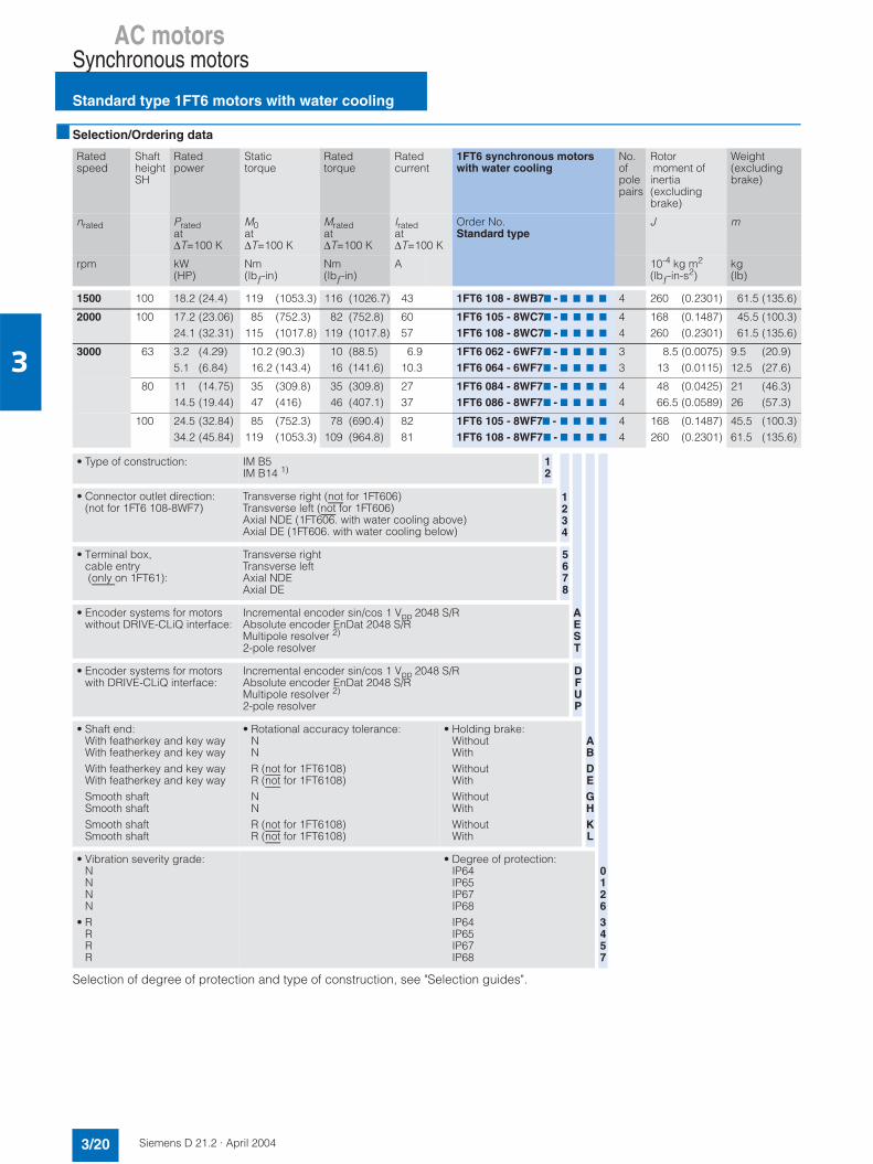
AC motorsSynchronous motors
Standard type 1FT6 motors with water cooling
3/20 Siemens D 21.2 · April 2004
3
Selection/Ordering data
Selection of degree of protection and type of construction, see "Selection guides".
Ratedspeed
ShaftheightSH
Ratedpower
Statictorque
Ratedtorque
Ratedcurrent
1FT6 synchronous motorswith water cooling
No.ofpolepairs
Rotor moment of inertia (excludingbrake)
Weight (excludingbrake)
nrated Pratedat∆T=100 K
M0at∆T=100 K
Mratedat∆T=100 K
Iratedat∆T=100 K
Order No.Standard type
J m
rpm kW(HP)
Nm(lbƒ-in)
Nm(lbƒ-in)
A 10-4 kg m2
(lbƒ-in-s2)kg(lb)
1500 100 18.2 (24.4) 119 (1053.3) 116 (1026.7) 43 1FT6 108 - 8WB77 - 7 7 7 7 4 260 (0.2301) 61.5 (135.6)
2000 100 17.2 (23.06)24.1 (32.31)
85 (752.3)115 (1017.8)
82 (752.8)119 (1017.8)
6057
1FT6 105 - 8WC77 - 7 7 7 7
1FT6 108 - 8WC77 - 7 7 7 7
44
168 (0.1487)260 (0.2301)
45.5 (100.3)61.5 (135.6)
3000 63 3.2 (4.29)5.1 (6.84)
10.2 (90.3)16.2 (143.4)
10 (88.5)16 (141.6)
6.910.3
1FT6 062 - 6WF77 - 7 7 7 7
1FT6 064 - 6WF77 - 7 7 7 7
33
8.5 (0.0075)13 (0.0115)
9.5 (20.9)12.5 (27.6)
80 11 (14.75)14.5 (19.44)
35 (309.8)47 (416)
35 (309.8)46 (407.1)
2737
1FT6 084 - 8WF77 - 7 7 7 7
1FT6 086 - 8WF77 - 7 7 7 7
44
48 (0.0425)66.5 (0.0589)
21 (46.3)26 (57.3)
100 24.5 (32.84)34.2 (45.84)
85 (752.3)119 (1053.3)
78 (690.4)109 (964.8)
8281
1FT6 105 - 8WF77 - 7 7 7 7
1FT6 108 - 8WF77 - 7 7 7 7
44
168 (0.1487)260 (0.2301)
45.5 (100.3)61.5 (135.6)
• Type of construction: IM B5IM B14 1)
12
• Connector outlet direction:(not for 1FT6 108-8WF7)
Transverse right (not for 1FT606)Transverse left (not for 1FT606)Axial NDE (1FT606. with water cooling above)Axial DE (1FT606. with water cooling below)
• Terminal box,cable entry (only on 1FT61):
Transverse rightTransverse leftAxial NDEAxial DE
5678
• Encoder systems for motors without DRIVE-CLiQ interface:
Incremental encoder sin/cos 1 Vpp 2048 S/RAbsolute encoder EnDat 2048 S/RMultipole resolver 2)
2-pole resolver
• Encoder systems for motors with DRIVE-CLiQ interface:
Incremental encoder sin/cos 1 Vpp 2048 S/RAbsolute encoder EnDat 2048 S/RMultipole resolver 2)
2-pole resolver
DFUP
• Shaft end:With featherkey and key wayWith featherkey and key wayWith featherkey and key wayWith featherkey and key waySmooth shaftSmooth shaftSmooth shaftSmooth shaft
• Rotational accuracy tolerance:NNR (not for 1FT6108)R (not for 1FT6108)NNR (not for 1FT6108)R (not for 1FT6108)
• Holding brake:WithoutWithWithoutWithWithoutWithWithoutWith
• Vibration severity grade:NNNN
• RRRR
• Degree of protection:IP64IP65IP67IP68IP64IP65IP67IP68
1234
AEST
ABDEGHKL
01263457

AC motorsSynchronous motors
Standard type 1FT6 motors with water cooling
3/21Siemens D 21.2 · April 2004
3
Selection/Ordering data
1) Same flange as type IM B5 but with metric thread inserts in the four mounting holes.2) A max. operating frequency of 470 Hz must be observed with SINAMICS. 3) With the specified motor module, the motor cannot be fully utilized to ∆T = 100 K winding temperature rise.
If a motor module with a higher rating is used, it must be checked whether the specified power cable can be connected to it.4) The current carrying capacity of the power cables corresponds to IEC 60204-1 for type of routing C under continuous operating conditions
with an ambient air temperature of +40 °C (+104 °F), designed for I0 (100 K), PVC/PUR-insulated cable.
Motor type(continued)
Staticcurrent
Calculated powerPcalc =M0 x nrated/9550
SINAMICS Motor ModuleRated output current
Power cable with complete shieldMotor connection (and brake connection) via power connector
I0at M0∆T=100 K
Pcalcfor M0∆T=100 K
Iratedat M0∆T=100 K
Order No. Power con-nector
Motorcablecross-sec-tion 4)
Order No.Pre-assembled cable
A kW(HP)
A Size mm2
1FT6 108 - 8WB7... 43 18.7 (25.1) 45 6SL3 120 - 1TE24 - 5AA0 3 4 x 16 6FX7 002 - 57S23 - 7 7 70
1FT6 105 - 8WC7...1FT6 108 - 8WC7...
5857
17.8 (23.9)24.9 (33.4)
6060
6SL3 120 - 1TE26 - 0AA0- 1TE26 - 0AA0
33
4 x 164 x 16
6FX7 002 - 57S23 - 7 7 70- 57S23 - 7 7 70
1FT6 062 - 6WF7...1FT6 064 - 6WF7...
6.910.3
3.2 (4.3)5.1 (6.8)
918
6SL3 120 - 7TE21 - 0AA0- 7TE21 - 8AA0
11
4 x 1.54 x 1.5
6FX7 002 - 57S01 - 7 7 70- 57S01 - 7 7 70
1FT6 084 - 8WF7...1FT6 086 - 8WF7...
24.534
11 (14.7)14.8 (19.8)
3045
6SL3 120 - 1TE23 - 0AA0- 1TE24 - 5AA0
1.51.5
4 x 44 x 10
6FX7 002 - 57S41 - 7 7 70- 57S64 - 7 7 70
1FT6 105 - 8WF7...1FT6 108 - 8WF7...
8386
26.7 (35.8)37.4 (50.1)
8585 3)
6SL3 120 - 1TE28 - 5AA0- 1TE28 - 5AA0
33
4 x 354 x 35
6FX5 002 - 5DS43 - 7 7 70- 5DS43 - 7 7 70
• Single Motor Module• Double Motor Module
12
Type of power cable
• MOTION-CONNECT 800• MOTION-CONNECT 500
• Without brake conductors• With brake conductors
See "MOTION-CONNECT connection system" for length code as well as power and signal cables.
85
CD
. ..
Notes on water cooling:• Incoming temperature of cooling water: Max. +30 °C (+86 °F)• Cooling water throughput: At least 5 l/min (5 l = 1.1 British
gallons/1.32 US gallons)• Pressure upstream of motor: pmax = 3 bar
• Cooling water connection: G 3/8"• Coolant: Water (up to max. 25% corrosion protection,
recommendation: Tyfocor)• Pressure loss between inlet and outlet < 0.1 bar

AC motorsSynchronous motors
Standard type 1FT6 motors with water cooling
3/22 Siemens D 21.2 · April 2004
3
Selection/Ordering data
Selection of degree of protection and type of construction, see "Selection guides".
Ratedspeed
ShaftheightSH
Ratedpower
Statictorque
Ratedtorque
Ratedcurrent
1FT6 synchronous motorswith water cooling
No.ofpolepairs
Rotormoment of inertia (excludingbrake)
Weight (excludingbrake)
nrated Pratedat∆T=100 K
M0at∆T=100 K
Mratedat∆T=100 K
Iratedat∆T=100 K
Order No.Standard type
J m
rpm kW(HP)
Nm(lbƒ-in)
Nm(lbƒ-in)
A 10-4 kg m2
(lbƒ-in-s2)kg(lb)
4500 63 4.7 (6.3)7.5 (10.05)
10.2 (90.3)16.2 (143.4)
10 (88.5)16 (141.6)
9.615.2
1FT6 062 - 6WH77 - 7 7 7 7
1FT6 064 - 6WH77 - 7 7 7 7
33
8.5 (0.0075)13 (0.0115)
9.5 (20.9)12.5 (27.6)
80 16.5 (22.12)21.2 (28.42)
35 (309.8)47 (416)
35 (309.8)45 (398.3)
3953
1FT6 084 - 8WH77 - 7 7 7 7
1FT6 086 - 8WH77 - 7 7 7 7
44
48 (0.0425)66.5 (0.0589)
21 (46.3)26 (57.3)
6000 63 6.2 (8.31)9.9 (13.27)
10.2 (90.3)16.2 (143.4)
9.8 (87)15.8 (139.8)
12.720
1FT6 062 - 6WK77 - 7 7 7 7
1FT6 064 - 6WK77 - 7 7 7 7
33
8.5 (0.0075)13 (0.0115)
9.5 (20.9)12.5 (27.6)
80 21.4 (28.69)27.7 (37.13)
35 (309.8)47 (416)
34 (300.9)44 (389.4)
5158
1FT6 084 - 8WK77 - 7 7 7 7
1FT6 086 - 8WK77 - 7 7 7 7
44
48 (0.0425)66.5 (0.0589)
21 (46.3)26 (57.3)
• Type of construction: IM B5IM B14 1)
12
• Connector outlet direction:(not for 1FT6 108-8WF7)
Transverse right (not for 1FT606)Transverse left (not for 1FT606)Axial NDE (1FT606. with water cooling above)Axial DE (1FT606. with water cooling below)
• Terminal box,cable entry (only on 1FT61...):
Transverse rightTransverse leftAxial NDEAxial DE
5678
• Encoder systems for motors without DRIVE-CLiQ interface:
Incremental encoder sin/cos 1 Vpp 2048 S/RAbsolute encoder EnDat 2048 S/RMultipole resolver 2)
2-pole resolver
• Encoder systems for motors with DRIVE-CLiQ interface:
Incremental encoder sin/cos 1 Vpp 2048 S/RAbsolute encoder EnDat 2048 S/RMultipole resolver 2)
2-pole resolver
DFUP
• Shaft end:With featherkey and key wayWith featherkey and key wayWith featherkey and key wayWith featherkey and key waySmooth shaftSmooth shaftSmooth shaftSmooth shaft
• Rotational accuracy tolerance:NNR (not for 1FT6108)R (not for 1FT6108)NNR (not for 1FT6108)R (not for 1FT6108)
• Holding brake:WithoutWithWithoutWithWithoutWithWithoutWith
• Vibration severity grade:NNNN
• RRRR
• Degree of protection:IP64IP65 IP67IP68IP64IP65IP67IP68
1234
AEST
ABDEGHKL
01263457

AC motorsSynchronous motors
Standard type 1FT6 motors with water cooling
3/23Siemens D 21.2 · April 2004
3
Selection/Ordering data
1) Same flange as type IM B5 but with metric thread inserts in the four mounting holes.2) A max. operating frequency of 470 Hz must be observed with SINAMICS.3) The current carrying capacity of the power cables corresponds to IEC 60204-1 for type of routing C under continuous operating conditions
with an ambient air temperature of +40 °C (+104 °F), designed for I0 (100 K), PVC/PUR-insulated cable.
Motor type(continued)
Staticcurrent
Calculated powerPcalc =M0 x nrated/9550
SINAMICS Motor ModuleRated output current
Power cable with complete shieldMotor connection (and brake connection) via power connector
I0at M0∆T=100 K
Pcalcfor M0∆T=100 K
Iratedat M0∆T=100 K
Order No. Power con-nector
Motorcablecross-sec-tion 3)
Order No.Pre-assembled cable
A kW(HP)
A Size mm2
1FT6 062 - 6WH7...1FT6 064 - 6WH7...
9.715.4
4.8 (6.43)7.6 (10.19)
1818
6SL3 120 - 7TE21 - 8AA0- 7TE21 - 8AA0
11
4 x 1.54 x 2.5
6FX7 002 - 57S01 - 7 7 70- 57S11 - 7 7 70
1FT6 084 - 8WH7...1FT6 086 - 8WH7...
3752
16.5 (22.12)22.1 (29.62)
4560
6SL3 120 - 1TE24 - 5AA0- 1TE26 - 0AA0
1.53
4 x 104 x 16
6FX7 002 - 57S64 - 7 7 70- 57S23 - 7 7 70
1FT6 062 - 6WK7...1FT6 064 - 6WK7...
12.920.5
6.4 (8.6)10.2 (13.67)
1830
6SL3 120 - 7TE21 - 8AA0- 1TE23 - 0AA0
11
4 x 1.54 x 2.5
6FX7 002 - 57S01 - 7 7 70- 57S11 - 7 7 70
1FT6 084 - 8WK7...1FT6 086 - 8WK7...
4759
22.0 (29.49)29.5 (39.54)
6060
6SL3 120 - 1TE26 - 0AA0- 1TE26 - 0AA0
33
4 x 164 x 16
6FX7 002 - 57S23 - 7 7 70- 5DS23 - 7 7 70
• Single Motor Module• Double Motor Module
12
Type of power cable
• MOTION-CONNECT 800• MOTION-CONNECT 500
• Without brake conductors• With brake conductors
See "MOTION-CONNECT connection system" for length code as well as power and signal cables.
85
CD
. ..
Notes on water cooling:• Incoming temperature of cooling water: Max. +30 °C (+86 °F)• Cooling water throughput: At least 5 l/min (5 l = 1.1 British
gallons/1.32 US gallons)• Pressure upstream of motor: pmax = 3 bar
• Cooling water connection: G 3/8"• Coolant: Water with up to max. 25% corrosion protection
(recommendation: Tyfocor)• Pressure loss between inlet and outlet < 0.1 bar
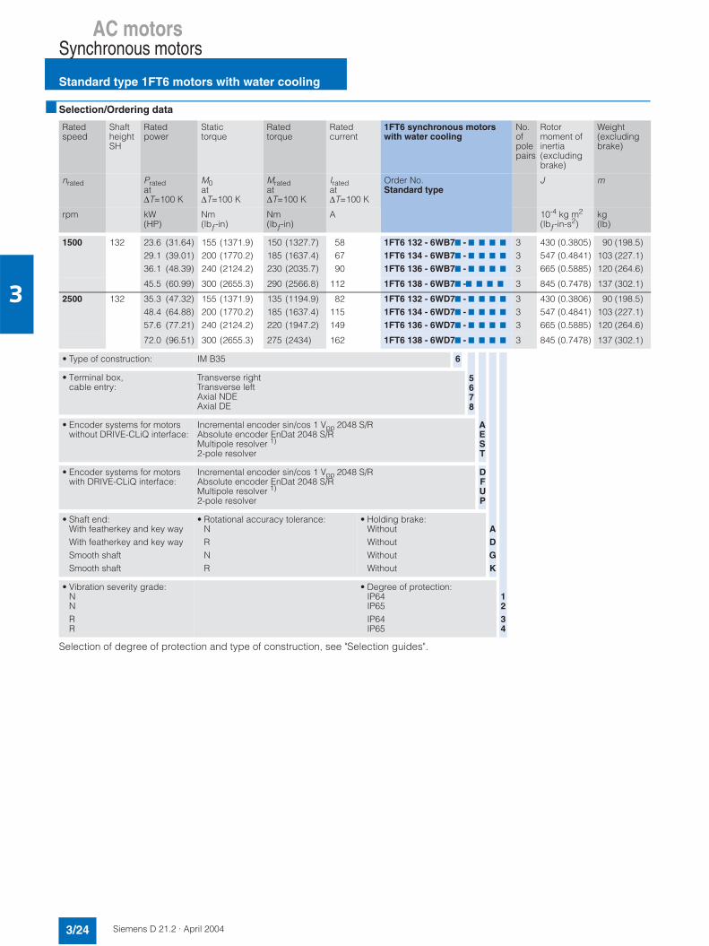
AC motorsSynchronous motors
Standard type 1FT6 motors with water cooling
3/24 Siemens D 21.2 · April 2004
3
Selection/Ordering data
Selection of degree of protection and type of construction, see "Selection guides".
Ratedspeed
ShaftheightSH
Ratedpower
Statictorque
Ratedtorque
Ratedcurrent
1FT6 synchronous motorswith water cooling
No.ofpolepairs
Rotormoment of inertia (excludingbrake)
Weight (excludingbrake)
nrated Pratedat∆T=100 K
M0at∆T=100 K
Mratedat∆T=100 K
Iratedat∆T=100 K
Order No.Standard type
J m
rpm kW(HP)
Nm(lbƒ-in)
Nm(lbƒ-in)
A 10-4 kg m2
(lbƒ-in-s2)kg(lb)
1500 132 23.6 (31.64)29.1 (39.01)36.1 (48.39)
155 (1371.9)200 (1770.2)240 (2124.2)
150 (1327.7)185 (1637.4)230 (2035.7)
586790
1FT6 132 - 6WB77 - 7 7 7 7
1FT6 134 - 6WB77 - 7 7 7 7
1FT6 136 - 6WB77 - 7 7 7 7
333
430 (0.3805)547 (0.4841)665 (0.5885)
90 (198.5)103 (227.1)120 (264.6)
45.5 (60.99) 300 (2655.3) 290 (2566.8) 112 1FT6 138 - 6WB77 -7 7 7 7 3 845 (0.7478) 137 (302.1)
2500 132 35.3 (47.32)48.4 (64.88)57.6 (77.21)
155 (1371.9)200 (1770.2)240 (2124.2)
135 (1194.9)185 (1637.4)220 (1947.2)
82115149
1FT6 132 - 6WD77 - 7 7 7 7
1FT6 134 - 6WD77 - 7 7 7 7
1FT6 136 - 6WD77 - 7 7 7 7
333
430 (0.3806)547 (0.4841)665 (0.5885)
90 (198.5)103 (227.1)120 (264.6)
72.0 (96.51) 300 (2655.3) 275 (2434) 162 1FT6 138 - 6WD77 - 7 7 7 7 3 845 (0.7478) 137 (302.1)
• Type of construction: IM B35 6
• Terminal box, cable entry:
Transverse rightTransverse leftAxial NDEAxial DE
• Encoder systems for motors without DRIVE-CLiQ interface:
Incremental encoder sin/cos 1 Vpp 2048 S/RAbsolute encoder EnDat 2048 S/RMultipole resolver 1)
2-pole resolver
• Encoder systems for motors with DRIVE-CLiQ interface:
Incremental encoder sin/cos 1 Vpp 2048 S/RAbsolute encoder EnDat 2048 S/RMultipole resolver 1)
2-pole resolver
DFUP
• Shaft end:With featherkey and key wayWith featherkey and key waySmooth shaftSmooth shaft
• Rotational accuracy tolerance:NRNR
• Holding brake:WithoutWithoutWithoutWithout
• Vibration severity grade:NNRR
• Degree of protection:IP64IP65IP64IP65
5678
AEST
ADGK
1234
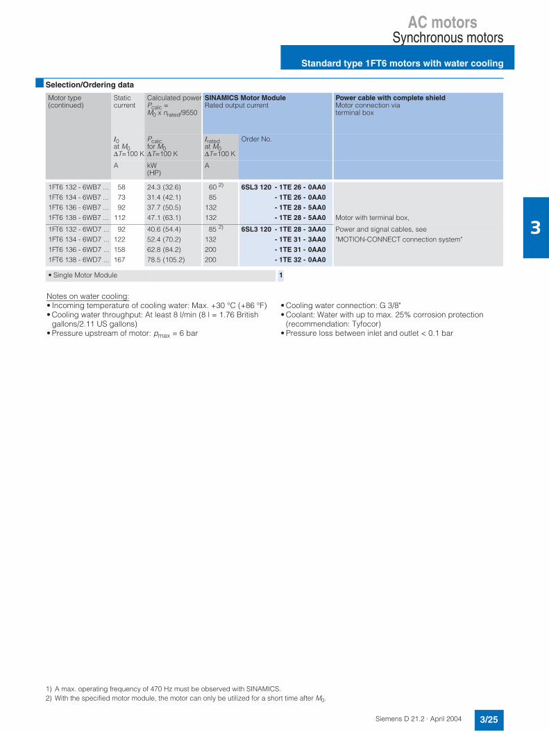
AC motorsSynchronous motors
Standard type 1FT6 motors with water cooling
3/25Siemens D 21.2 · April 2004
3
Selection/Ordering data
1) A max. operating frequency of 470 Hz must be observed with SINAMICS. 2) With the specified motor module, the motor can only be utilized for a short time after M0.
Motor type(continued)
Staticcurrent
Calculated powerPcalc =M0 x nrated/9550
SINAMICS Motor ModuleRated output current
Power cable with complete shieldMotor connection via terminal box
I0at M0∆T=100 K
Pcalcfor M0∆T=100 K
Iratedat M0∆T=100 K
Order No.
A kW(HP)
A
1FT6 132 - 6WB7 ...1FT6 134 - 6WB7 ...1FT6 136 - 6WB7 ...1FT6 138 - 6WB7 ...
587392
112
24.3 (32.6)31.4 (42.1)37.7 (50.5)47.1 (63.1)
60 2)
85132132
6SL3 120 - 1TE 26 - 0AA0- 1TE 26 - 0AA0- 1TE 28 - 5AA0- 1TE 28 - 5AA0 Motor with terminal box,
1FT6 132 - 6WD7 ...1FT6 134 - 6WD7 ...1FT6 136 - 6WD7 ...1FT6 138 - 6WD7 ...
92122158167
40.6 (54.4)52.4 (70.2)62.8 (84.2)78.5 (105.2)
85 2)
132200200
6SL3 120 - 1TE 28 - 3AA0- 1TE 31 - 3AA0- 1TE 31 - 0AA0- 1TE 32 - 0AA0
Power and signal cables, see"MOTION-CONNECT connection system"
• Single Motor Module 1
Notes on water cooling:• Incoming temperature of cooling water: Max. +30 °C (+86 °F)• Cooling water throughput: At least 8 l/min (8 l = 1.76 British
gallons/2.11 US gallons)• Pressure upstream of motor: pmax = 6 bar
• Cooling water connection: G 3/8"• Coolant: Water with up to max. 25% corrosion protection
(recommendation: Tyfocor)• Pressure loss between inlet and outlet < 0.1 bar
AC motors
Notes
3/26 Siemens D 21.2 · April 2004
3

AC motorsSynchronous motors
1FK7 motors
3/27Siemens D 21.2 · April 2004
3
Overview
1FK7 motors are extremely compact permanent-magnet syn-chronous motors. The available options, gear units and encoders, together with the expanded product range, mean that 1FK7 motors can be optimized to meet the requirements of any application. They therefore also satisfy the permanently increasing demands of state-of-the-art machine generations.1FK7 motors can be combined with the SINAMICS S drivesystem to create powerful systems with high functionality. The built-in encoder systems for speed and position control can be selected depending on the application.
The motors are designed for operation without external coolingand the heat is dissipated via the motor surface. 1FK7 motorshave a high overload capability.
Benefits
1FK7 Compact motors offer the following benefits:7 Space-saving installation thanks to very high power density7 Can be used universally for numerous applications7 Wide motor spectrum.
1FK7 High Dynamic motors offer the following benefits:7 Extremely high dynamic response due to low moment of iner-
tia of rotor.
Applications
• Machine tools• Robots and manipulators• Wood, glass, ceramics and stone working• Packaging, plastics and textile machines• Auxiliary axes.
Technical data
1) A max. operating frequency of 470 Hz must be observed with SINAMICS.
Type of motor Permanent-magnet synchronous motor
Magnetic material Rare-earth magnetic material
Insulation of the stator winding inaccordance with EN 60034-1 (IEC 60034-1)
Temperature class F for a winding temperature rise of ∆T = 100 K at an ambient temperature of +40 °C (+104°F)
Type according toEN 60034-7 (IEC 60034-7)
IM B5 (IM V1, IM V3)
Degree of protection according toEN 60034-5 (IEC 60034-5)
IP64
Cooling Natural
Temperature monitoring KTY 84 temperature sensor in stator winding
Paint finish Unpainted
Shaft end on the drive end in accor-dance with DIN 748-3 (IEC 60072-1)
Smooth shaft
2nd rating plate3rd rating plate
Applied to end shieldSupplied separately packed
Radial eccentricity, concentricity, and axial eccentricityin accordance with DIN 42955(IEC 60072-1)
Tolerance N (normal)
Vibration severity in accordance with EN 60034-14 (IEC 60034-14)
Level N (normal)
Max. sound pressure levelLpA (1 m) acc. to EN ISO 1680
1FK702: 55 dB 1FK703: 55 dB 1FK704: 55 dB 1FK706: 65 dB 1FK708: 70 dB 1FK710: 70 dB
Encoder systems, built-in, for motors with/withoutDRIVE-CLiQ interface
• Incremental encoder sin/cos1 Vpp 2048 pulses/revolution
• Absolute encoder, multiturn, 2048 pulses/revolution on 1FK704 to 1FK710.512 pulses/revolution on 1FK702 and 1FK703 und traversingrange 4096 revolu-tions with EnDat interface
• Simple absolute encoder,multiturn, 32 pulses/revolution and traversing range 4096 revo-lutions with EnDat interface
• Multipole resolver 1)
(number of poles corresponds to number of pole pairs of the motor)
• 2-pole resolver
Connecting Connectors for signals and power can be rotated (270°)
Options • Shaft end on the drive end with featherkey and featherkey way (half-key balancing)
• Built-in holding brake• Degree of protection IP65,
additional IP67 drive end flange• Planetary gear unit (requires
smooth shaft end)• Anthracite gray paint finish

AC motorsSynchronous motorsCore type 1FK7 Compact motors with natural cooling
3/28 Siemens D 21.2 · April 2004
3
Selection/Ordering data
Selection of degree of protection and type of construction, see "Selection guides".
Ratedspeed
ShaftheightSH
Ratedpower
Static torque Ratedtorque 1)
Ratedcurrent
1FK7 Compactsynchronous motorwith natural cooling
No.ofpolepairs
Rotor moment of inertia(excludingbrake)
Weight (excludingbrake)
nrated Pratedat∆T=100 K
M0at∆T=100 K
Mratedat∆T=100 K
Iratedat∆T=100 K
Order No.Core type
J m
rpm kW(HP)
Nm(lbƒ-in)
Nm(lbƒ-in)
A 10-4 kg m2
(lbƒ-in-s2)kg(lb)
2000 100 7.75 (10.39) 48 (424.8) 37 (327.5) 16 1FK7 105 - 5AC71 - 17 7 7 4 156 (0.1381) 39 (85)
3000 48 0.82 (1.1) 3 (26.6) 2.6 (23) 1.95 1FK7 042 - 5AF71 - 17 7 7 4 3.01(0.0027) 4.9 (10.8)
63 1.48 (1.98)2.29 (3.07)
6 (53.1)11 (97.4)
4.7 (41.6)7.3 (64.6)
3.75.6
1FK7 060 - 5AF71 - 17 7 7
1FK7 063 - 5AF71 - 17 7 7
44
7.95(0.0070)15.1 (0.0134)
7 (15.4)11.5 (25.4)
80 2.14 (2.87)3.3 (4.42)
8 (70.8)16 (141.6)
6.8 (60.2)10.5 (92.9)
4.47.4
1FK7 080 - 5AF71 - 17 7 7
1FK7 083 - 5AF71 - 17 7 7
44
15 (0.0133)27.3 (0.0242)
10 (22.1)14 (30.9)
100 3.77 (5.05)4.87 (6.53)5.372) (7.2)2)
8.17 (10.95)
18 (159.3)27 (238)36 (318.6)48 (424.8)
12 (106.1)15.5 (137.2)20.52) (181.4)2)
26 (230.1)
811.816.5 2)
18
1FK7 100 - 5AF71 - 17 7 7
1FK7 101 - 5AF71 - 17 7 7
1FK7 103 - 5AF71 - 17 7 7
1FK7 105 - 5AF71 - 17 7 7
4444
55.3 (0.0489)79.9 (0.0707)
105 (0.0929)156 (0.1381)
19 (41.9)21 (46.3)29 (63.9)39 (85)
4500 63 1.74 (2.33)2.093) (2.8)3)
6 (53.1)11 (97.4)
3.7 (32.7)5 3) (44.3)3)
4.16.1 3)
1FK7 060 - 5AH71- 17 7 7
1FK7 063 - 5AH71- 17 7 7
44
7.95(0.0070)15.1 (0.0134)
7 (15.4)11.5 (25.4)
80 2.39 (3.2)3.044) (4.8)4)
8 (70.8)16 (141.6)
5.7 (50.5)8.34) (73.5)4)
5.6 9 4)
1FK7 080 - 5AH71- 17 7 7
1FK7 083 - 5AH71- 17 7 7
44
15 (0.0133)27.3 (0.0242)
10 (22.1)14 (30.9)
6000 28 0.4 (0.54) 0.85(7.5) 0.6 (5.3) 1.4 1FK7 022 - 5AK71- 17 7 7 3 0.28(0.0002) 1.8 (4)
36 0.47 (0.63) 1.1 (9.7) 0.8 (7.1) 1.4 1FK7 032 - 5AK71- 17 7 7 3 0.61(0.0005) 2.7 (6)
48 0.69 (0.92) 1.6 (14.2)3 (26.6)
1.1 (9.7)25) (17.7)7)
1.7 1FK7 040 - 5AK71- 17 7 7 4 1.69(0.0015) 3.5 (7.7)
1.025) (1.41)5) 3.1 5) 1FK7 042 - 5AK71- 17 7 7 4 3.01(0.0027) 4.9 (10.8)
• Encoder systems for motors without DRIVE-CLiQ interface:
Incremental encoder sin/cos 1 Vpp 2048 pulses/revolutionAbsolute encoder EnDat 2048 pulses/revolution 1)
(not for 1FK702, 1FK703)Absolute encoder EnDat 512 pulses/revolution 1)
(not for 1FK702, 1FK703)Single absolute encoder EnDat 32 pulses/revolution 1)
(not for 1FK702, 1FK703)Multipole resolver 6)
2-pole resolver
AE
H
G
ST
• Encoder systems for motors with DRIVE-CLiQ interface:
Incremental encoder sin/cos 1 Vpp 2048 pulses/revolutionAbsolute encoder EnDat 2048 S/R 1)
(not for 1FK702, 1FK703)Single absolute encoder EnDat 32 pulses/revolutionAbsolute encoder EnDat 512 S/R 1)
(not for 1FK702, 1FK703)Multipole resolver 6)
2-pole resolver
DF
KL
UP
• Shaft end:With featherkey and key wayWith featherkey and key waySmooth shaftSmooth shaft
Rotational accu-racy tolerance:NNNN
Holding brake:
WithoutWithWithoutWith
• Degree of protection: IP64IP65 and additional IP67 drive end flangeIP64, anthracite gray paint finishIP65 and additional IP67 drive end flange, anthracite gray paint finishIP65 and additional IP67 drive end flange, anthracite gray paint finishand metal rating plate on motor
ABGH
02358

AC motorsSynchronous motors
Core type 1FK7 Compact motorswith natural cooling
3/29Siemens D 21.2 · April 2004
3
Selection and ordering data
1) If the absolute encoder is used, Mrated is reduced by 10%.2) These values refer to n = 2500 rpm.3) These values refer to n = 4000 rpm.4) These values refer to n = 3500 rpm.5) These values refer to n = 5000 rpm.6) A max. operating frequency of 470 Hz must be observed with SINAMICS. 7) With the specified motor module, the motor cannot be fully to ∆T = 100 K winding temperature rise. If a motor module with a higher rating is used,
it must be checked whether the specified power cable can be connected to it.8) The current carrying capacity of the power cables corresponds to IEC 60204-1 for type of routing C under continuous operating conditions with an
ambient air temperature of +40 °C (+104 °F), designed for I0 (100 K), PVC/PUR-insulated cable.
Motor type(continued)
Staticcurrent
CalculatedpowerPcalc =M0 x nrated/9550
SINAMICS Motor ModuleRated output current
Power cable with complete shieldMotor connection (and brake connection) via power connector
I0at M0∆T=100 K
Pcalcfor M0∆T=100 K
Iratedat M0∆T=100 K
Order No. Power con-nector
Motor cable cross-sec-tion 8)
Order No.Pre-assembled cable
A kW(HP)
A Size mm2
1FK7 105 - 5AC71... 20 10 (13.4) 30 6SL3 120 - 7TE23 - 0AA0 1.5 4 x 2.5 6FX7 002 - 57S31 - 7 7 70
1FK7 042 - 5AF71... 2.2 0.9 (1.2) 3 6SL3 120 - 7TE13 - 0AA0 1 4 x 1.5 6FX7 002 - 57S01 - 7 7 70
1FK7 060 - 5AF71...1FK7 063 - 5AF71...
4.58
1.9 (2.5)3.5 (4.7)
59
6SL3 120 - 7TE15 - 0AA0- 7TE21 - 0AA0
11
4 x 1.54 x 1.5
6FX7 002 - 57S01 - 7 7 70- 57S01 - 7 7 70
1FK7 080 - 5AF71...1FK7 083 - 5AF71...
4.810.4
2.5 (3.4)5 (6.7)
59 7)
6SL3 120 - 7TE15 - 0AA0- 7TE21 - 0AA0
11
4 x 1.54 x 1.5
6FX7 002 - 57S01 - 7 7 70- 57S01 - 7 7 70
1FK7 100 - 5AF71...1FK7 101 - 5AF71...1FK7 103 - 5AF71...1FK7 105 - 5AF71...
11.21927.531
5.7 (7.6)8.5 (11.4)
11.3 (15.1)10 (13.4)
1818 7)
3030 7)
6SL3 120 - 7TE21 - 8AA0- 7TE21 - 8AA0- 1TE23 - 0AA0- 7TE23 - 0AA0
11.51.51.5
4 x 1.54 x 2.54 x 44 x 10
6FX7 002 - 57S01 - 7 7 70- 57S31 - 7 7 70- 57S41 - 7 7 70- 57S61 - 7 7 70
1FK7 060 - 5AH71...1FK7 063 - 5AH71...
6.212
2.8 (3.8)5.2 (7)
918
6SL3 120 - 7TE21 - 0AA0- 7TE21 - 8AA0
11
4 x 1.54 x 1.5
6FX7 002 - 57S01 - 7 7 70- 57S01 - 7 7 70
1FK7 080 - 5AH71...1FK7 083 - 5AH71...
7.415
3.8 (5.1)7.5 (10.1)
918
6SL3 120 - 7TE21 - 0AA0- 7TE21 - 8AA0
11
4 x 1.54 x 1.5
6FX7 002 - 57S01 - 7 7 70- 57S01 - 7 7 70
1FK7 022 - 5AK71... 1.8 0.5 (0.7) 3 6SL3 120 - 7TE13 - 0AA0 1 4 x 1.5 6FX7 002 - 57S01 - 7 7 70
1FK7 032 - 5AK71... 1.7 0.7 (0.9) 3 6SL3 120 - 7TE13 - 0AA0 1 4 x 1.5 6FX7 002 - 57S01 - 7 7 70
1FK7 040 - 5AK71... 2.25 1 (1.3) 3 6SL3 120 - 7TE13 - 0AA0 1 4 x 1.5 6FX7 002 - 57S01 - 7 7 70
1FK7 042 - 5AK71... 4.4 1.9 (2.5) 5 - 7TE15 - 0AA0 1 4 x 1.5 - 57S01 - 7 7 70
• Single Motor Module• Double Motor Module
12
Type of power cable
• MOTION-CONNECT 800• MOTION-CONNECT 500
• Without brake conductors• With brake conductors
See "MOTION-CONNECT connection system" for length code as well as power and signal cables.
85
CD
. ..
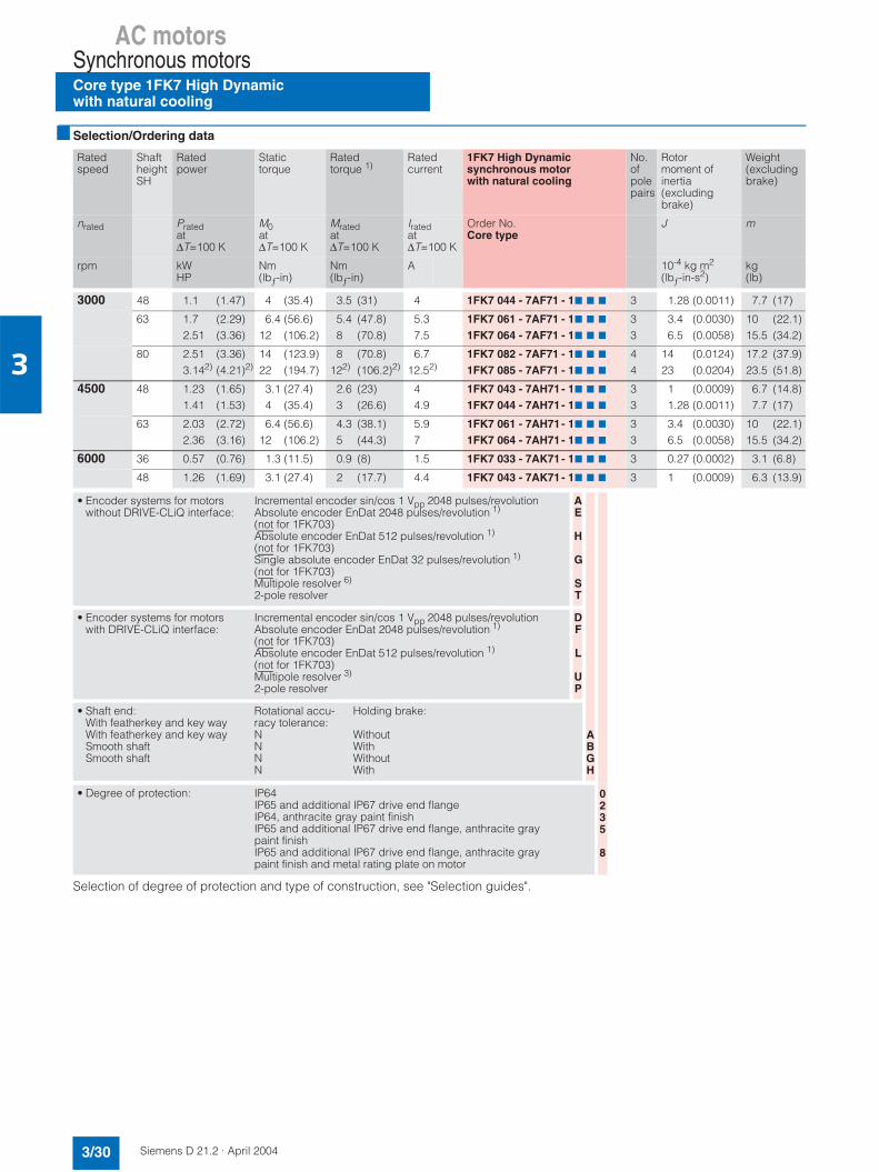
AC motorsSynchronous motorsCore type 1FK7 High Dynamicwith natural cooling
3/30 Siemens D 21.2 · April 2004
3
Selection/Ordering data
Selection of degree of protection and type of construction, see "Selection guides".
Ratedspeed
ShaftheightSH
Ratedpower
Statictorque
Ratedtorque 1)
Ratedcurrent
1FK7 High Dynamic synchronous motorwith natural cooling
No.ofpolepairs
Rotormoment of inertia (excludingbrake)
Weight (excludingbrake)
nrated Pratedat∆T=100 K
M0at∆T=100 K
Mratedat∆T=100 K
Iratedat∆T=100 K
Order No.Core type
J m
rpm kWHP
Nm(lbƒ-in)
Nm(lbƒ-in)
A 10-4 kg m2
(lbƒ-in-s2)kg(lb)
3000 48 1.1 (1.47) 4 (35.4) 3.5 (31) 4 1FK7 044 - 7AF71 - 17 7 7 3 1.28 (0.0011) 7.7 (17)
63 1.7 (2.29)2.51 (3.36)
6.4 (56.6)12 (106.2)
5.4 (47.8)8 (70.8)
5.37.5
1FK7 061 - 7AF71 - 17 7 7
1FK7 064 - 7AF71 - 17 7 7
33
3.4 (0.0030)6.5 (0.0058)
10 (22.1)15.5 (34.2)
80 2.51 (3.36)3.142) (4.21)2)
14 (123.9)22 (194.7)
8 (70.8)122) (106.2)2)
6.712.52)
1FK7 082 - 7AF71 - 17 7 7
1FK7 085 - 7AF71 - 17 7 7
44
14 (0.0124)23 (0.0204)
17.2 (37.9)23.5 (51.8)
4500 48 1.23 (1.65)1.41 (1.53)
3.1 (27.4)4 (35.4)
2.6 (23)3 (26.6)
44.9
1FK7 043 - 7AH71- 17 7 7
1FK7 044 - 7AH71- 17 7 7
33
1 (0.0009)1.28 (0.0011)
6.7 (14.8)7.7 (17)
63 2.03 (2.72)2.36 (3.16)
6.4 (56.6)12 (106.2)
4.3 (38.1)5 (44.3)
5.97
1FK7 061 - 7AH71- 17 7 7
1FK7 064 - 7AH71- 17 7 7
33
3.4 (0.0030)6.5 (0.0058)
10 (22.1)15.5 (34.2)
6000 36 0.57 (0.76) 1.3 (11.5) 0.9 (8) 1.5 1FK7 033 - 7AK71- 17 7 7 3 0.27 (0.0002) 3.1 (6.8)
48 1.26 (1.69) 3.1 (27.4) 2 (17.7) 4.4 1FK7 043 - 7AK71- 17 7 7 3 1 (0.0009) 6.3 (13.9)
• Encoder systems for motors without DRIVE-CLiQ interface:
Incremental encoder sin/cos 1 Vpp 2048 pulses/revolutionAbsolute encoder EnDat 2048 pulses/revolution 1)
(not for 1FK703)Absolute encoder EnDat 512 pulses/revolution 1)
(not for 1FK703)Single absolute encoder EnDat 32 pulses/revolution 1)
(not for 1FK703)Multipole resolver 6)
2-pole resolver
AE
H
G
ST
• Encoder systems for motors with DRIVE-CLiQ interface:
Incremental encoder sin/cos 1 Vpp 2048 pulses/revolutionAbsolute encoder EnDat 2048 pulses/revolution 1)
(not for 1FK703)Absolute encoder EnDat 512 pulses/revolution 1)
(not for 1FK703)Multipole resolver 3)
2-pole resolver
DF
L
UP
• Shaft end:With featherkey and key wayWith featherkey and key waySmooth shaft Smooth shaft
Rotational accu-racy tolerance:NNNN
Holding brake:
WithoutWithWithoutWith
• Degree of protection: IP64IP65 and additional IP67 drive end flangeIP64, anthracite gray paint finishIP65 and additional IP67 drive end flange, anthracite gray paint finishIP65 and additional IP67 drive end flange, anthracite gray paint finish and metal rating plate on motor
ABGH
0235
8
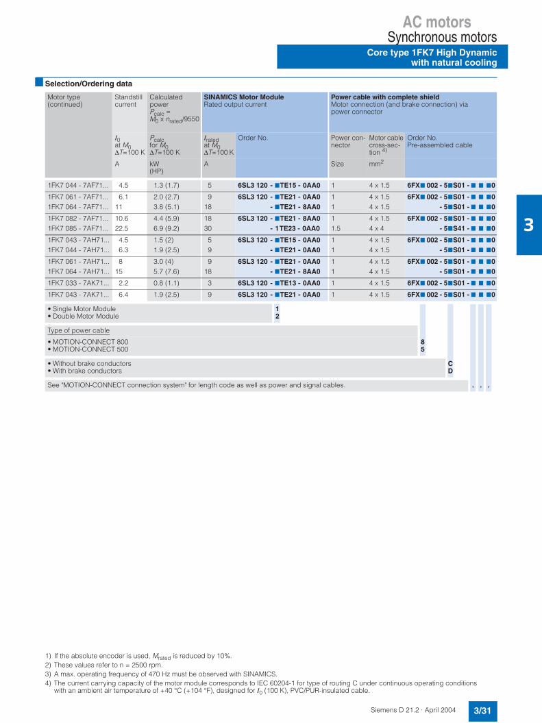
AC motorsSynchronous motors
Core type 1FK7 High Dynamicwith natural cooling
3/31Siemens D 21.2 · April 2004
3
Selection/Ordering data
1) If the absolute encoder is used, Mrated is reduced by 10%.2) These values refer to n = 2500 rpm.3) A max. operating frequency of 470 Hz must be observed with SINAMICS. 4) The current carrying capacity of the motor module corresponds to IEC 60204-1 for type of routing C under continuous operating conditions
with an ambient air temperature of +40 °C (+104 °F), designed for I0 (100 K), PVC/PUR-insulated cable.
Motor type(continued)
Standstillcurrent
CalculatedpowerPcalc =M0 x nrated/9550
SINAMICS Motor ModuleRated output current
Power cable with complete shieldMotor connection (and brake connection) via power connector
I0at M0∆T=100 K
Pcalcfor M0∆T=100 K
Iratedat M0∆T=100 K
Order No. Power con-nector
Motor cable cross-sec-tion 4)
Order No.Pre-assembled cable
A kW(HP)
A Size mm2
1FK7 044 - 7AF71... 4.5 1.3 (1.7) 5 6SL3 120 - 7TE15 - 0AA0 1 4 x 1.5 6FX7 002 - 57S01 - 7 7 70
1FK7 061 - 7AF71...1FK7 064 - 7AF71...
6.111
2.0 (2.7)3.8 (5.1)
918
6SL3 120 - 7TE21 - 0AA0- 7TE21 - 8AA0
11
4 x 1.54 x 1.5
6FX7 002 - 57S01 - 7 7 70- 57S01 - 7 7 70
1FK7 082 - 7AF71...1FK7 085 - 7AF71...
10.622.5
4.4 (5.9)6.9 (9.2)
1830
6SL3 120 - 7TE21 - 8AA0- 1TE23 - 0AA0
11.5
4 x 1.54 x 4
6FX7 002 - 57S01 - 7 7 70- 57S41 - 7 7 70
1FK7 043 - 7AH71...1FK7 044 - 7AH71...
4.56.3
1.5 (2)1.9 (2.5)
59
6SL3 120 - 7TE15 - 0AA0- 7TE21 - 0AA0
11
4 x 1.54 x 1.5
6FX7 002 - 57S01 - 7 7 70- 57S01 - 7 7 70
1FK7 061 - 7AH71...1FK7 064 - 7AH71...
815
3.0 (4)5.7 (7.6)
918
6SL3 120 - 7TE21 - 0AA0- 7TE21 - 8AA0
11
4 x 1.54 x 1.5
6FX7 002 - 57S01 - 7 7 70- 57S01 - 7 7 70
1FK7 033 - 7AK71... 2.2 0.8 (1.1) 3 6SL3 120 - 7TE13 - 0AA0 1 4 x 1.5 6FX7 002 - 57S01 - 7 7 70
1FK7 043 - 7AK71... 6.4 1.9 (2.5) 9 6SL3 120 - 7TE21 - 0AA0 1 4 x 1.5 6FX7 002 - 57S01 - 7 7 70
• Single Motor Module• Double Motor Module
12
Type of power cable
• MOTION-CONNECT 800• MOTION-CONNECT 500
• Without brake conductors• With brake conductors
See "MOTION-CONNECT connection system" for length code as well as power and signal cables.
85
CD
. ..
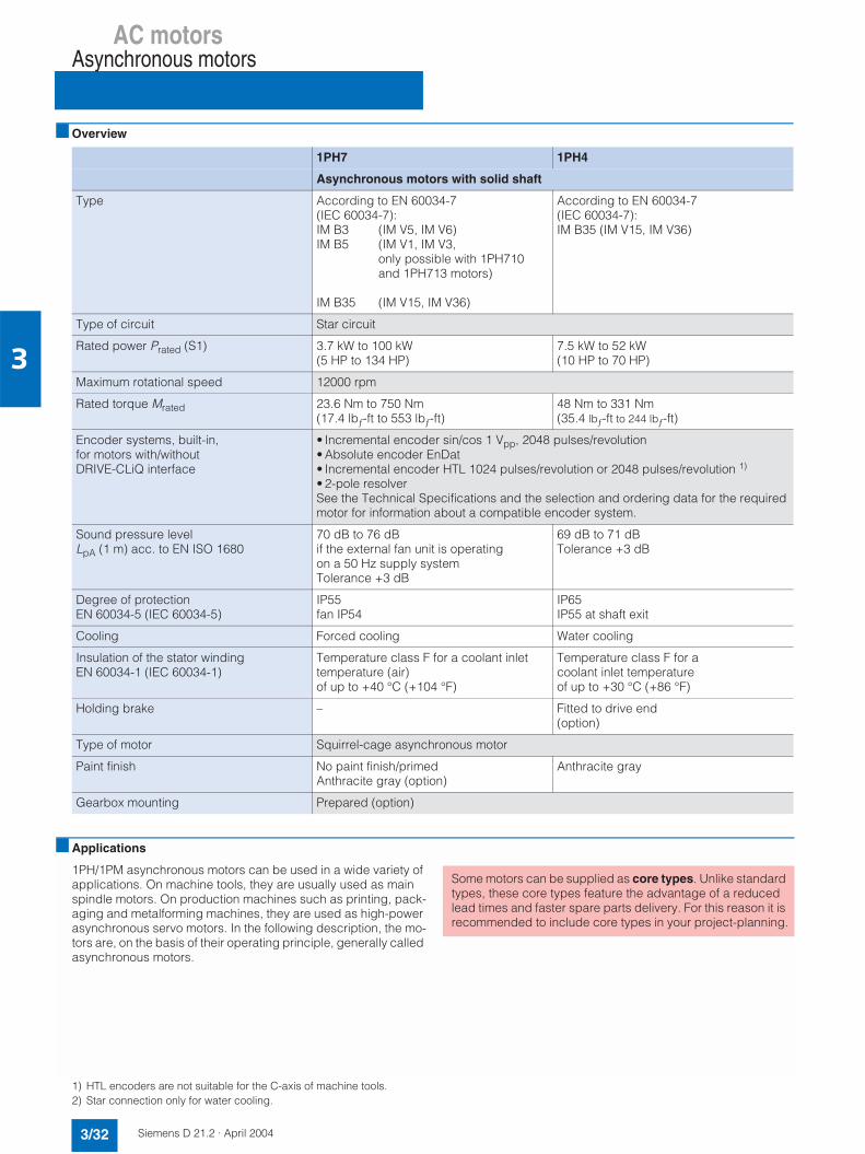
AC motorsAsynchronous motors
3/32 Siemens D 21.2 · April 2004
3
Overview
1) HTL encoders are not suitable for the C-axis of machine tools.2) Star connection only for water cooling.
1PH7 1PH4
Asynchronous motors with solid shaft
Type According to EN 60034-7 (IEC 60034-7):IM B3 (IM V5, IM V6)IM B5 (IM V1, IM V3,
only possible with 1PH710 and 1PH713 motors)
IM B35 (IM V15, IM V36)
According to EN 60034-7 (IEC 60034-7):IM B35 (IM V15, IM V36)
Type of circuit Star circuit
Rated power Prated (S1) 3.7 kW to 100 kW(5 HP to 134 HP)
7.5 kW to 52 kW(10 HP to 70 HP)
Maximum rotational speed 12000 rpm
Rated torque Mrated 23.6 Nm to 750 Nm(17.4 lbƒ-ft to 553 lbƒ-ft)
48 Nm to 331 Nm (35.4 lbƒ-ft to 244 lbƒ-ft)
Encoder systems, built-in, for motors with/without DRIVE-CLiQ interface
• Incremental encoder sin/cos 1 Vpp, 2048 pulses/revolution• Absolute encoder EnDat• Incremental encoder HTL 1024 pulses/revolution or 2048 pulses/revolution 1)
• 2-pole resolverSee the Technical Specifications and the selection and ordering data for the requiredmotor for information about a compatible encoder system.
Sound pressure level LpA (1 m) acc. to EN ISO 1680
70 dB to 76 dBif the external fan unit is operating on a 50 Hz supply systemTolerance +3 dB
69 dB to 71 dBTolerance +3 dB
Degree of protectionEN 60034-5 (IEC 60034-5)
IP55fan IP54
IP65IP55 at shaft exit
Cooling Forced cooling Water cooling
Insulation of the stator winding EN 60034-1 (IEC 60034-1)
Temperature class F for a coolant inlet temperature (air)of up to +40 °C (+104 °F)
Temperature class F for a coolant inlet temperature of up to +30 °C (+86 °F)
Holding brake – Fitted to drive end (option)
Type of motor Squirrel-cage asynchronous motor
Paint finish No paint finish/primedAnthracite gray (option)
Anthracite gray
Gearbox mounting Prepared (option)
Applications
1PH/1PM asynchronous motors can be used in a wide variety of applications. On machine tools, they are usually used as main spindle motors. On production machines such as printing, pack-aging and metalforming machines, they are used as high-power asynchronous servo motors. In the following description, the mo-tors are, on the basis of their operating principle, generally called asynchronous motors.
Some motors can be supplied as core types. Unlike standard types, these core types feature the advantage of a reduced lead times and faster spare parts delivery. For this reason it is recommended to include core types in your project-planning.
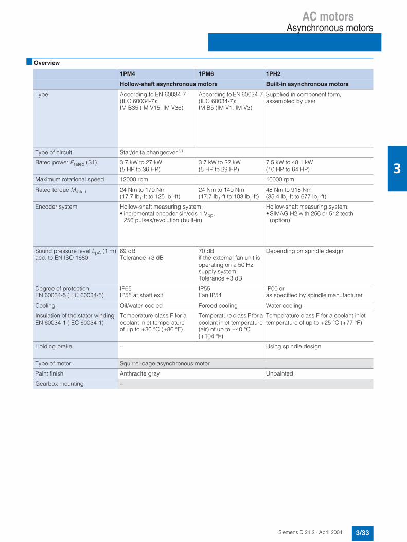
AC motorsAsynchronous motors
3/33Siemens D 21.2 · April 2004
3
Overview
1PM4 1PM6 1PH2
Hollow-shaft asynchronous motors Built-in asynchronous motors
Type According to EN 60034-7(IEC 60034-7):IM B35 (IM V15, IM V36)
According to EN 60034-7 (IEC 60034-7):IM B5 (IM V1, IM V3)
Supplied in component form,assembled by user
Type of circuit Star/delta changeover 2)
Rated power Prated (S1) 3.7 kW to 27 kW(5 HP to 36 HP)
3.7 kW to 22 kW(5 HP to 29 HP)
7.5 kW to 48.1 kW(10 HP to 64 HP)
Maximum rotational speed 12000 rpm 10000 rpm
Rated torque Mrated 24 Nm to 170 Nm(17.7 lbƒ-ft to 125 lbƒ-ft)
24 Nm to 140 Nm(17.7 lbƒ-ft to 103 lbƒ-ft)
48 Nm to 918 Nm(35.4 lbƒ-ft to 677 lbƒ-ft)
Encoder system Hollow-shaft measuring system:• incremental encoder sin/cos 1 Vpp,
256 pulses/revolution (built-in)
Hollow-shaft measuring system:• SIMAG H2 with 256 or 512 teeth
(option)
Sound pressure level LpA (1 m)acc. to EN ISO 1680
69 dB Tolerance +3 dB
70 dBif the external fan unit is operating on a 50 Hz supply systemTolerance +3 dB
Depending on spindle design
Degree of protectionEN 60034-5 (IEC 60034-5)
IP65IP55 at shaft exit
IP55Fan IP54
IP00 or as specified by spindle manufacturer
Cooling Oil/water-cooled Forced cooling Water cooling
Insulation of the stator winding EN 60034-1 (IEC 60034-1)
Temperature class F for a coolant inlet temperature of up to +30 °C (+86 °F)
Temperature class F for a coolant inlet temperature (air) of up to +40 °C (+104 °F)
Temperature class F for a coolant inlet temperature of up to +25 °C (+77 °F)
Holding brake – Using spindle design
Type of motor Squirrel-cage asynchronous motor
Paint finish Anthracite gray Unpainted
Gearbox mounting –

AC motorsAsynchronous motors
1PH7 motors
3/34 Siemens D 21.2 · April 2004
3
1PH7 motors (SH 100 to SH 160 and SH 180/SH 225)
Overview
Air-cooled 1PH7 motors are rugged, low-maintenance 4-pole squirrel-cage asynchronous motors.A fan for providing separate ventilation is mounted axially on the rear of the motor. The normal direction of air flow is from the drive end to the non-drive end in order to keep the exhaust heat of the motor away from the machine. The reverse air direction can be ordered as an option.The motors are equipped with a built-in encoder system forsensing the motor speed and indirect position. On machinetools, the encoder system is capable of C-axis operation as stan-dard. An additional encoder is therefore not required for C-axis operation.
Benefits
7 Short overall length of motor7 Minimal overall dimension due to the integrated terminal box
(SH 100 to SH 160)7 Maximum speeds of up to 9000 rpm (option: 12000 rpm)7 Full rated torque continuously available, even at standstill7 Optimum matching to the power levels SINAMICS S.
Applications
• Small compact machine tools• Complex machining centers and lathes• Special machines• Printing industry:
- Single drives for printing units• Rubber, plastic, wire and glass manufacturing:
- Drives for extruders, calenders, rubber injection molding, film machines, non-woven textile machines,
- Wire-drawing machines, wire-stranding machines, etc.• General applications such as coiler and winder drives.
Technical data (general)
Technical data (core type)
1) The sound pressure level can be reduced if the fan is operated on a 60 Hz supply system with option K44.
2) A sound baffle to reduce the sound pressure level is obtainable for a shaft heights of 225 with option G15.
3) DE is the drive end with shaft.NDE is the non-drive end.
4) For permissible loads, refer to the 1PH Motors Planning Guide.5) HTL encoders are not suitable for the C-axis of machine tools.
Insulation of the stator winding in accordance with EN 60034-1 (IEC 60034-1)
Temperature class F for a coolant inlet temperatureof up to +40 °C (+104 °F)
Motor fan ratings 3 AC 400 V ±10%, 50/60 Hz3 AC 480 V +5% -10%, 66 Hz
Encoder systems, built-in, for motors with/withoutDRIVE-CLiQ interface
Incremental encoder sin/cos1 Vpp, 2048 pulses/revolution,Absolute encoder EnDat,Incremental encoder HTL 5)
2-pole resolver
Terminal box connection type• Motor Terminals in terminal box• Fans Terminals in terminal box• Motor encoder and PTC thermistor 12/17-pin circular socket
(without mating connector)Type according toEN 60034-7 (IEC 60034-7)
IM B3IM B35
Rating plates 1 supplied separatelypacked in terminal box
Permissible coolant temperature -15 °C to +40 °C(+5 °F to +104 °F)
Temperature monitoring KTY 84 temperature sensor in stator winding
Sound pressure level LpA (1 m) acc. to EN ISO 1680(tolerance +3 dB)
From DE to NDE (with the fan operating on a 50 Hz supply system)1PH710.: 70 dB1PH713.: 70 dB1PH716.: 75 dB 1)
1PH718.: 73 dB 2)
1PH722.: 76 dB 2)
Type acc. to EN 60034-7 (IEC 60034-7)
1PH710: IM B5 (IM V1, IM V3)1PH713: IM B5 (IM V1, IM V3)1PH716: IM B35 (IM V15, IM V36)
Terminal box location(facing drive end 3))
Top, cable entry from right
Bearing arrangement at drive end 4) Bearing for belt or coupling output
Vibration severity in accordance with EN 60034-14 (IEC 60034-14)
Stage S
Shaft and flange accuracyaccording to DIN 42955 (IEC 60072-1)
Tolerance R (reduced)
Degree of protection according toEN 60034-5 (IEC 60034-5)
Motor IP55, fan IP54
Paint finish Unpainted

AC motorsAsynchronous motors
1PH7 motors
3/35Siemens D 21.2 · April 2004
3
Characteristics
Typical power-speed diagram for AC motors 1)
The diagram shows the typical ratio between motor speed and drive power for 1PH7 motors in the following duty types (accord-ing to IEC 60034-1):
S 1: Continuous dutyS 6: Continuous duty with intermittent loading and a relative ON
period of 60% (S6-60%) or 40% (S6-40%) with a maximum duty cycle time of 10 min.
S 2: Short-time operation with an ON period of 30 min (S2-30 min) followed by standstill.
1) For further planning information refer to the 1PH Motors Planning Guide.2) Values from the power-speed diagram based on using an Active Line Module on a 3 AC 400 V supply system. If using a Smart Line Module, proceed
in accordance with the 1PH Planning Guide.
)&
")"*
")%*
)&
")"*
")%*
+
'
+
,-
./
Motor Ratedspeed
Attainable speed for ratedpower in duty type(according to IEC 60034-1)
Type nrated n22)
S1 S6-60% S6-40% S2-30 min
rpm rpm rpm rpm rpm
1PH7 101-..F 1500 8200 7000 6000 6500
1PH7 103-..D1PH7 103-..F1PH7 103-..G
100015002000
375050009000
375046007500
310039006400
335045006900
1PH7 105-..F 1500 7900 6750 5750 6150
1PH7 107-..D1PH7 107-..F1PH7 107-..G
100015002000
580065007000
480062007000
410052506900
465056507000
1PH7 131-..F 1500 6700 5500 4500 5000
1PH7 133-..D1PH7 133-..F1PH7 133-..G
100015002000
470068006500
370056006500
280045005900
345051006450
1PH7 135-..F 1500 7500 6200 5200 5650
1PH7 137-..D1PH7 137-..F1PH7 137-..G
100015002000
540070006000
450070006000
360062005800
410068006000
1PH7 163-..B1PH7 163-..D1PH7 163-..F1PH7 163-..G
500100015002000
2500580055003500
1900480055003500
1500400055003500
1730440055003500
1PH7 167-..B1PH7 167-..D1PH7 167-..F1PH7 167-..G
500100015002000
2100625045003250
1600520045003250
1250430045003250
1400470045003250
1PH7 184-..T1PH7 184-..D1PH7 184-..E1PH7 184-..F1PH7 184-..L
5001000125015002500
45005000500050005000
38004400468050005000
33503600419050005000
33503600360050005000
1PH7 186-..T1PH7 186-..D1PH7 186-..E
50010001250
480050005000
410046504260
358038503780
400038503580
1PH7 224-..C1PH7 224-..D1PH7 224-..F
70010001500
302045004500
257045004330
229041004000
217037303890

AC motorsAsynchronous motors
Core type 1PH7 motors
3/36 Siemens D 21.2 · April 2004
3
Selection/Ordering data
ShaftheightSH
Ratedspeed
Max. permanentspeed
Max. speed 3) Rated power for duty type (according to IEC 60034-1)
1PH7 asynchronous motor
nrated nS1 cont.1) nS1 cont.
2) nmax nmax4) Prated Order No.
Core typeS1 S6-60% S6-40% S2-
30 minrpm rpm rpm rpm rpm kW
(HP)kW(HP)
kW(HP)
kW(HP)
100 2000 5500 – 9000 – 7 (9.4) 8.5 (11.4) 10 (13.4) 9.25 (12.4) 1PH7 103 - 7 7G02 - 0C70
1500 5500 – 9000 – 9 (12.1) 11 (14.7) 13 (17.4) 12 (16.1) 1PH7 107 - 7 7F02 - 0C70
132 10002000
4500 – 8000 – 12 (16.1)20 (26.8)
15 (20.1)25 (33.5)
18.5 (24.8)30 (40.2)
16 (21.4)27.5 (36.9)
1PH7 133 - 7 7D02 - 0C701PH7 133 - 7 7G02 - 0C70
10002000
4500 – 8000 – 17 (22.8)28 (37.5)
20.5 (27.5)35 (46.9)
25 (33.5)43 (57.6)
22.5 (30.2)39 (52.3)
1PH7 137 - 7 7D02 - 0C701PH7 137 - 7 7G02 - 0C70
160 10001500
3700 – 6500 – 22 (29.5)30 (40)
27 (36.2)37 (49.6)
33 (44.2)45 (60.3)
30 (40.2)41 (55)
1PH7 163 - 7 7D03 - 0C701PH7 163 - 7 7F03 - 0C70
1500 3700 – 6500 – 37 (49.6) 46 (61.7) 56 (75.1) 51 (68.4) 1PH7 167 - 7 7F03 - 0C70
• Fans: External fan unit, PG cable entry in terminal boxExternal fan unit, metric cable entry in terminal box
27
• Encoder systems for motors withoutDRIVE-CLiQ interface:
Incremental encoder sin/cos 1 Vpp (without C or D track)
• Encoder systems for motors with DRIVE-CLiQinterface:
Incremental encoder sin/cos 1 Vpp (without C or D track) Q
• Type of construction: 5) IM B5 (IM V1, IM V3)IM B35 (IM V15, IM V36)
• Drive end shaft extension: FeatherkeySmooth shaft
• Balancing:Half-key–
• Direction of air flow (fan): DE → NDEDE → NDE
• Exhaust direction
AxialAxial
N
23
AJ
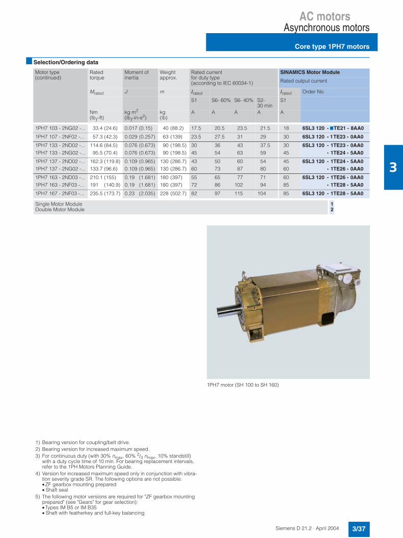
AC motorsAsynchronous motors
Core type 1PH7 motors
3/37Siemens D 21.2 · April 2004
3
Selection/Ordering data
Motor type(continued)
Ratedtorque
Moment of inertia
Weight approx.
Rated current for duty type(according to IEC 60034-1)
SINAMICS Motor Module
Rated output current
Mrated J m Irated Irated Order No.
S1 S6- 60% S6- 40% S2-30 min
S1
Nm(lbƒ-ft)
kg m2
(lbƒ-in-s2)kg(lb)
A A A A A
1PH7 103 - 2NG02 -... 33.4 (24.6) 0.017 (0.15) 40 (88.2) 17.5 20.5 23.5 21.5 18 6SL3 120 - 7TE21 - 8AA0
1PH7 107 - 2NF02 -... 57.3 (42.3) 0.029 (0.257) 63 (139) 23.5 27.5 31 29 30 6SL3 120 - 1TE23 - 0AA0
1PH7 133 - 2ND02 -...1PH7 133 - 2NG02 -...
114.6 (84.5)95.5 (70.4)
0.076 (0.673)0.076 (0.673)
90 (198.5)90 (198.5)
3045
3654
4363
37.559
3045
6SL3 120 - 1TE23 - 0AA0- 1TE24 - 5AA0
1PH7 137 - 2ND02 -...1PH7 137 - 2NG02 -...
162.3 (119.8)133.7 (96.6)
0.109 (0.965)0.109 (0.965)
130 (286.7)130 (286.7)
4360
5073
6087
5480
4560
6SL3 120 - 1TE24 - 5AA0- 1TE26 - 0AA0
1PH7 163 - 2ND03 -...1PH7 163 - 2NF03 -...
210.1 (155)191 (140.9)
0.19 (1.681)0.19 (1.681)
180 (397)180 (397)
5572
6586
77102
7194
6085
6SL3 120 - 1TE26 - 0AA0- 1TE28 - 5AA0
1PH7 167 - 2NF03 -... 235.5 (173.7) 0.23 (2.035) 228 (502.7) 82 97 115 104 85 6SL3 120 - 1TE28 - 5AA0
Single Motor ModuleDouble Motor Module
12
1) Bearing version for coupling/belt drive.2) Bearing version for increased maximum speed.3) For continuous duty (with 30% nmax, 60% 2/3 nmax, 10% standstill)
with a duty cycle time of 10 min. For bearing replacement intervals, refer to the 1PH Motors Planning Guide.
4) Version for increased maximum speed only in conjunction with vibra-tion severity grade SR. The following options are not possible:• ZF gearbox mounting prepared• Shaft seal
5) The following motor versions are required for "ZF gearbox mountingprepared" (see "Gears" for gear selection):•Types IM B5 or IM B35• Shaft with featherkey and full-key balancing
1PH7 motor (SH 100 to SH 160)
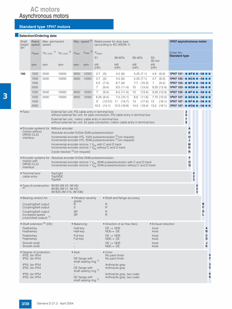
AC motorsAsynchronous motors
Standard type 1PH7 motors
3/38 Siemens D 21.2 · April 2004
3
Selection/Ordering data
ShaftheightSH
Ratedspeed
Max. permanentspeed
Max. speed 3) Rated power for duty type(according to IEC 60034-1)
1PH7 asynchronous motor
nrated nS1 cont.1) nS1 cont.
2) nmax nmax4) Prated Order No.
Standard typeS1 S6-60% S6-40% S2-
30 minrpm rpm rpm rpm rpm kW
(HP)kW(HP)
kW(HP)
kW(HP)
100 1500 5500 10000 9000 12000 3.7 (5) 4.5 (6) 5.25 (7.1) 4.9 (6.6) 1PH7 101 - 7 7F7 7 - 07 7 7
100015002000
5500 10000 9000 12000 3.7 (5)5.5 (7.4)7 (9.4)
4.5 (6)6.7 (9)8.5 (11.4)
5.25 (7.1)7.7 (10.3)
10 (13.4)
4.7 (6.3)7 (9.4)9.25 (12.4)
1PH7 103 - 7 7D7 7 - 07 7 7
1PH7 103 - 7 7F 7 7 - 07 7 7
1PH7 103 - 7 7G7 7 - 07 7 7
1500 5500 10000 9000 12000 7 (9.4) 8.5 (11.4) 10 (13.4) 9.25 (12.4) 1PH7 105 - 7 7F 7 7 - 07 7 7
100015002000
5500 10000 9000 12000 6.25 (8.4)9 (12.01)
10.5 (14.1)
7.5 (10.1)11 (14.7)12.5 (16.8)
8.8 (11.8)13 (17.4)14.5 (19.4)
7.75 (10.4)12 (16.1)13.5 (18.1)
1PH7 107 - 7 7D7 7 - 07 7 7
1PH7 107 - 7 7F 7 7 - 07 7 7
1PH7 107 - 7 7G7 7 - 07 7 7
• Fans: External fan unit, PG cable entry in terminal boxwithout external fan unit, for pipe connection, PG cable entry in terminal boxExternal fan unit, metric cable entry in terminal boxwithout external fan unit, for pipe connection, metric cable entry in terminal box
2678
• Encoder systems for motors withoutDRIVE-CLiQinterface:
Without encoderAbsolute encoder EnDat 2048 pulses/revolutionIncremental encoder HTL 1024 pulses/revolution 5) (on request)Incremental encoder HTL 2048 pulses/revolution 5) (on request)Incremental encoder sin/cos 1 Vpp with C and D trackIncremental encoder sin/cos 1 Vpp without C and D track2-pole resolver 5) (on request)
• Encoder systems for motors with DRIVE-CLiQinterface:
Absolute encoder EnDat 2048 pulses/revolutionIncremental encoder sin/cos 1 Vpp 2048 pulses/revolution with C and D trackIncremental encoder sin/cos 1 Vpp 2048 pulses/revolution without C and D track
FDQ
• Terminal box/cable entry:
Top/rightTop/NDETop/left
• Type of construction: 6)
IM B3 (IM V5, IM V6)IM B5 (IM V1, IM V3)IM B35 (IM V15, IM V36)
• Bearing version for:
Coupling/belt outputCoupling/belt outputCoupling/belt outputIncreased speed(clutch/belt output) 7)
• Vibration severity gradeRSSRSR
• Shaft and flange accuracy
RRRR
• Shaft extension 6) (DE):FeatherkeyFeatherkeyFeatherkeyFeatherkeySmooth shaftSmooth shaft
• Balancing:Half-keyHalf-keyFull-keyFull-key––
• Direction of air flow (fan):DE → NDENDE→ DEDE → NDENDE→ DEDE → NDENDE→ DE
• Exhaust directionAxialAxialAxialAxialAxialAxial
• Degree of protection:IP55, fan IP54IP55, fan IP54
IP55, fan IP54IP55, fan IP54
IP55, fan IP54IP55, fan IP54
• Seal:–DE flange withshaft sealing ring 7)
–DE flange withshaft sealing ring 7)
–DE flange withshaft sealing ring 7)
• Color:No paint finishNo paint finish
Anthracite grayAnthracite gray
Anthracite gray, two coatsAnthracite gray, two coats
AEHJMNR
023
023
BCDL
ABCDJK
02
35
68
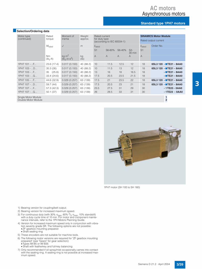
AC motorsAsynchronous motors
Standard type 1PH7 motors
3/39Siemens D 21.2 · April 2004
3
Selection/Ordering data
Motor type(continued)
Ratedtorque
Moment of inertia
Weight approx.
Rated current for duty type(according to IEC 60034-1)
SINAMICS Motor Module
Rated output current
Mrated J m Irated Irated Order No.
S1 S6-60% S6-40% S2-30 min
S1
Nm(lbƒ-ft)
kg m2
(lbƒ-in-s2)kg(lb)
A A A A A
1PH7 101 - ..F... 23.6 (17.4) 0.017 (0.150) 40 (88.2) 10 11.5 12.5 12 18 6SL3 120 - 7TE21 - 8AA0
1PH7 103 - .. D...1PH7 103 - ..F...1PH7 103 - ..G...
35.3 (26)35 (25.8)33.4 (24.6)
0.017 (0.150)0.017 (0.150)0.017 (0.150)
40 (88.2)40 (88.2)40 (88.2)
101317.5
11.51620.5
131823.5
1216.521.5
181818
6SL3 120 - 7TE21 - 8AA0- 7TE21 - 8AA0- 7TE21 - 8AA0
1PH7 105 - ..F... 44.6 (32.9) 0.029 (0.257) 63 (139) 17.5 21 23.5 22 18 6SL3 120 - 7TE21 - 8AA0
1PH7 107 - ..D...1PH7 107 - ..F...1PH7 107 - ..G...
59.7 (44)57.3 (42.3)50.1 (37)
0.029 (0.257)0.029 (0.257)0.029 (0.257)
63 (139)63 (139)63 (139)
17.523.526
20.527.528.5
233133
212931
183030
6SL3 120 - 7TE21 - 8AA0- 1TE23 - 0AA0- 1TE23 - 0AA0
Single Motor ModuleDouble Motor Module
12
1) Bearing version for coupling/belt output.2) Bearing version for increased maximum speed.3) For continuous duty (with 30% nmax, 60% 2/3 nmax, 10% standstill)
with a duty cycle time of 10 min. For motor and component mainte-nance intervals, refer to the 1PH Motors Planning Guide.
4) Version for increased maximum speed only in conjunction with vibra-tion severity grade SR. The following options are not possible:• ZF gearbox mounting prepared• Shaft sealing ring
5) These encoders are not suitable for machine tools.6) The following motor versions are required for "ZF gearbox mounting
prepared" (see "Gears" for gear selection):•Types IM B5 or IM B35• Shaft with featherkey and full-key balancing
7) Only recommended if oil spray/mist occasionally cames into contact with the sealing ring. A sealing ring is not possible at increased max-imum speed.
1PH7 motor (SH 100 to SH 160)

AC motorsAsynchronous motors
Standard type 1PH7 motors
3/40 Siemens D 21.2 · April 2004
3
Selection/Ordering data
ShaftheightSH
Ratedspeed
Max. permanentspeed
Max. speed 3) Rated power for duty type(according to IEC 60034-1)
1PH7 asynchronous motor
nrated nS1 cont.1) nS1 cont.
2) nmax nmax4) Prated Order No.
Standard typeS1 S6-60% S6-40% S2-
30 minrpm rpm rpm rpm rpm kW
(HP)kW(HP)
kW(HP)
kW(HP)
132 1500 4500 8500 8000 10000 11 (14.7) 13.5 (18.1) 16.5 (22.1) 15 (20.1) 1PH7 131 - 7 7F 7 7 - 07 7 7
100015002000
4500 8500 8000 10000 12 (16.1)15 (20.1)20 (26.8)
15 (20.1)18.5 (24.8)25 (33.5)
18.5 (24.8)23 (30.8)30 (40.2)
16 (21.4)20.5 (27.5)27.5 (36.9)
1PH7 133 - 7 7D7 7 - 07 7 7
1PH7 133 - 7 7F 7 7 - 07 7 7
1PH7 133 - 7 7G7 7 - 07 7 7
1500 4500 8500 8000 10000 18.5 (24.8) 23 (30.8) 28 (37.5) 25.5 (34.2) 1PH7 135 - 7 7F 7 7 - 07 7 7
100015002000
4500 8500 8000 10000 17 (22.8)22 (22.8)28 (37.5)
20.5 (27.5)27.5 (36.9)35 (46.9)
25 (33.5)33 (44.2)43 (57.6)
22.5 (30.2)30 (40.2)39 (52.3)
1PH7 137 - 7 7D7 7 - 07 7 7
1PH7 137 - 7 7F 7 7 - 07 7 7
1PH7 137 - 7 7G7 7 - 07 7 7
• Fans: External fan unit, PG cable entry in terminal boxwithout external fan unit, for pipe connection, PG cable entry in terminal boxExternal fan unit, metric cable entry in terminal boxwithout external fan unit, for pipe connection, metric cable entry in terminal box
2678
• Encoder systems for motors withoutDRIVE-CLiQinterface:
Without encoderAbsolute encoder EnDat 2048 pulses/revolutionIncremental encoder HTL 1024 pulses/revolution 5)
Incremental encoder HTL 2048 pulses/revolution 5)
Incremental encoder sin/cos 1 Vpp with C and D track7)
Incremental encoder sin/cos 1 Vpp without C and D track2-pole resolver 5)
• Encoder systems for motors with DRIVE-CLiQinterface:
Absolute encoder EnDat 2048 pulses/revolutionIncremental encoder sin/cos 1 Vpp 2048 pulses/revolution with C and D trackIncremental encoder sin/cos 1 Vpp 2048 pulses/revolution without C and D track
FDQ
• Terminal box/cable entry:
Top/rightTop/NDETop/left
• Type of construction: 6)
IM B3 (IM V5, IM V6)IM B5 (IM V1, IM V3)IM B35 (IM V15, IM V36)
• Bearing version for:
Coupling/belt outputCoupling/belt outputCoupling/belt outputIncreased speed(clutch/belt output) 7)
• Vibration severity gradeRSSRSR
• Shaft and flange accuracy
RRRR
• Shaft extension 6) (DE):FeatherkeyFeatherkeyFeatherkeyFeatherkeySmooth shaftSmooth shaft
• Balancing:Half-keyHalf-keyFull-keyFull-key––
• Direction of air flow (fan):DE → NDENDE→ DEDE → NDENDE→ DEDE → NDENDE→ DE
• Exhaust directionAxialAxialAxialAxialAxialAxial
• Degree of protection:IP55, fan IP54IP55, fan IP54
IP55, fan IP54IP55, fan IP54
IP55, fan IP54IP55, fan IP54
• Seal:–DE flange withshaft sealing ring 7)
–DE flange withshaft sealing ring 7)
–DE flange withshaft sealing ring 7)
• Color:No paint finishNo paint finish
Anthracite grayAnthracite gray
Anthracite gray, two coatsAnthracite gray, two coats
AEHJMNR
023
023
BCDL
ABCDJK
02
35
68

AC motorsAsynchronous motors
Standard type 1PH7 motors
3/41Siemens D 21.2 · April 2004
3
Selection/Ordering data
Motor type(continued)
Ratedtorque
Moment of inertia
Weight approx.
Rated current for duty type(according to IEC 60034-1)
SINAMICS Motor Module
Rated output current
Mrated J m Irated Irated Order No.
S1 S6-60% S6-40% S2-30 min
S1
Nm(lbƒ-ft)
kg m2
(lbƒ-in-s2)kg(lb)
A A A A A
1PH7 131 - ..F... 70 (51.6) 0.076 (0.673) 90 (198.5) 24 29 34 31.5 30 6SL3 120 - 1TE23 - 0AA0
1PH7 133 - ..D...1PH7 133 - ..F...1PH7 133 - ..G...
114.6 (84.5)95.5 (70.4)95.5 (70.4)
0.076 (0.673)0.076 (0.673)0.076 (0.673)
90 (198.5)90 (198.5)90 (198.5)
303445
364154
434963
37.543.559
304545
6SL3 120 - 1TE23 - 0AA0- 1TE24 - 5AA0- 1TE24 - 5AA0
1PH7 135 - ..F... 117.8 (86.9) 0.109 (0.965) 130 (286.7) 42 50 58 54 45 6SL3 120 - 1TE24 - 5AA0
1PH7 137 - ..D...1PH7 137 - ..F...1PH7 137 - ..G...
162.3 (119.7)140.1 (103.3)133.7 (98.6)
0.109 (0.965)0.109 (0.965)0.109 (0.965)
130 (286.7)130 (286.7)130 (286.7)
435760
506873
607987
547380
456060
6SL3 120 - 1TE24 - 5AA0- 1TE26 - 0AA0- 1TE26 - 0AA0
Single Motor Module 1
1) Bearing version for coupling/belt output.2) Bearing version for increased maximum speed.3) For continuous duty (with 30% nmax, 60% 2/3 nmax, 10% standstill)
with a duty cycle time of 10 min. For motor and component mainte-nance intervals, refer to the 1PH Motors Planning Guide.
4) Version for increased maximum speed only in conjunction with vibra-tion severity grade SR. The following options are not possible:• ZF gearbox mounting prepared• Shaft sealing ring
5) These encoders are not suitable for machine tools.6) The following motor versions are required for "ZF gearbox mounting
prepared" (see "Gears" for gear selection):•Types IM B5 or IM B35• Shaft with featherkey and full-key balancing
7) Only recommended if oil spray/mist occasionally gets onto the seal-ing ring. A sealing ring is not possible at increased maximum speed.
1PH7 motor (SH 100 to SH 160)

AC motorsAsynchronous motors
Standard type 1PH7 motors
3/42 Siemens D 21.2 · April 2004
3
Selection/Ordering data
ShaftheightSH
Ratedspeed
Max. permanentspeed
Max. speed 3) Rated power for duty type (according to IEC 60034-1)
1PH7 asynchronous motor
nrated nS1 cont.1) nS1 cont.
2) nmax nmax4) Prated Order No.
Standard typeS1 S6-60% S6-40% S2-
30 minrpm rpm rpm rpm rpm kW
(HP)kW(HP)
kW(HP)
kW(HP)
160 500100015002000
3700 7000 6500 8000 12 (16.1)22 (29.5)30 (40.2)36 (48.3)
15 (20.1)27 (36.2)37 (49.6)44 (59)
18 (24.1)33 (44.2)45 (60.3)52 (69.7)
16.5 (22.1)30 (40.2)41 (55)48 (64.3)
1PH7 163 - 7 7B7 7 - 07 7 7
- 7 7D7 7 - 07 7 7
- 7 7F 7 7 - 07 7 7
- 7 7G7 7 - 07 7 7
500100015002000
3700 7000 6500 8000 16 (21.4)28 (37.5)37 (49.6)41 (55)
19.5 (26.1)34.5 (46.2)46 (61.7)51 (68.4)
24 (32.2)42 (56.3)56 (75.1)61 (81.8)
21.5 (28.8)38 (51)51 (68.3)56 (75.1)
1PH7 167 - 7 7B7 7 - 07 7 7
- 7 7D7 7 - 07 7 7
- 7 7F7 7 - 07 7 7
- 7 7G7 7 - 07 7 7
• Fans: External fan unit, PG cable entry in terminal boxwithout external fan unit, for pipe connection, PC cable entry in terminal boxExternal fan unit, metric cable entry in terminal boxwithout external fan unit, for pipe connection, metric cable entry in terminal box
2678
• Encoder systems for motors withoutDRIVE-CLiQinterface:
Without encoderAbsolute encoder EnDat 2048 pulses/revolutionIncremental encoder HTL 1024 pulses/revolution 5)
Incremental encoder HTL 2048 pulses/revolution 5)
Incremental encoder sin/cos 1 Vpp with C and D track5)
Incremental encoder sin/cos 1 Vpp without C and D track2-pole resolver 5)
• Encoder systems for motors with DRIVE-CLiQinterface:
Absolute encoder EnDat 2048 pulses/revolutionIncremental encoder sin/cos 1 Vpp 2048 pulses/revolution with C and D trackIncremental encoder sin/cos 1 Vpp 2048 pulses/revolution without C and D track
FDQ
• Terminal box/cable entry:
Top/rightTop/NDETop/left
• Type of construction: 1)
IM B3 (IM V5, IM V6)IM B35 (IM V15, IM V36)
• Bearing version for:
Coupling/belt outputCoupling/belt outputCoupling/belt outputIncreased speed(clutch/belt output) 7)
• Vibration severity gradeRSSRSR
• Shaft and flange accuracy
RRRR
• Shaft extension 6) (DE):FeatherkeyFeatherkeyFeatherkeyFeatherkeySmooth shaftSmooth shaft
• Balancing:Half-keyHalf-keyFull-keyFull-key––
• Direction of air flow (fan):DE → NDENDE→ DEDE → NDENDE→ DEDE → NDENDE→ DE
• Exhaust direction:AxialAxialAxialAxialAxialAxial
• Degree of protection:IP55, fan IP54IP55, fan IP54
IP55, fan IP54IP55, fan IP54
IP55, fan IP54IP55, fan IP54
• Seal:–DE flange withshaft seal 7)
–DE flange withshaft seal 7)
–DE flange withshaft seal 7)
• Color:No paint finishNo paint finish
Anthracite grayAnthracite gray
Anthracite gray, two coatsAnthracite gray, two coats
AEHJMNR
023
03
BCDL
ABCDJK
02
35
68

AC motorsAsynchronous motors
Standard type 1PH7 motors
3/43Siemens D 21.2 · April 2004
3
Selection/Ordering data
Motor type(continued)
Ratedtorque
Moment of inertia
Weight approx.
Rated current for duty type(according to IEC 60034-1)
SINAMICS Motor Module
Rated output current
Mrated J m Irated Irated Order No.
S1 S6- 60% S6- 40% S2-30 min
S1
Nm(lbƒ-ft)
kg m2
(lbƒ-in-s2)kg(lb)
A A A A A
1PH7 163 - ..B...1PH7 163 - .. D...1PH7 163 - ..F...1PH7 163 - .. G...
229.2 (169.1)210.1 (155)191 (140.9)171.9 (126.8)
0.19 (1.681)0.19 (1.681)0.19 (1.681)0.19 (1.681)
180 (397)180 (397)180 (397)180 (397)
30557285
366586
100
4277
102114
397194
107
30608585
6SL3 120 - 1TE23 - 0AA0- 1TE26 - 0AA0- 1TE28 - 5AA0- 1TE28 - 5AA0
1PH7 167 - .. B...1PH7 167 - ..D...1PH7 167 - .. F...1PH7 167 - .. G...
305.5 (225.3)267.4 (197.2)235.5 (173.7)195.8 (144.4)
0.23 (2.035)0.23 (2.035)0.23 (2.035)0.23 (2.035)
228 (503)228 (503)228 (503)228 (503)
37718289
448597
106
53100115124
4892
104115
458585
132
6SL3 120 - 1TE24 - 5AA0- 1TE28 - 5AA0- 1TE28 - 5AA0- 1TE31 - 3AA0
Single Motor Module 1
1) Bearing version for coupling/belt output.2) Bearing version for increased maximum speed.3) For continuous duty (with 30% nmax, 60% 2/3 nmax, 10% standstill) with
a duty cycle time of 10 min. For motor and component maintenance intervals, refer to the 1PH Motors Planning Guide.
4) Version for increased maximum speed only in conjunction with vibra-tion severity grade SR. The following options are not possible:• ZF gearbox mounting prepared• Shaft seal
5) These encoders are not suitable for machine tools.6) The following motor versions are required for "ZF gearbox mounting
prepared" (see "Gears" for gear selection):•Types IM B5 or IM B35• Shaft with featherkey and full-key balancing
7) Only recommended if oil spray/mist occasionally comes into contact with the sealing ring. A sealing ring is not possible at increased max-imum speed.
1PH7 motor (SH 100 to SH 160)

AC motorsAsynchronous motors
Standard type 1PH7 motors
3/44 Siemens D 21.2 · April 2004
3
Selection/Ordering data
ShaftheightSH
Ratedspeed
Max. permanent speed
Max. speed 4)
Rated powerfor duty type (according to IEC 60034-1)
1PH7 asynchronous motor
nrated nS1 cont.1) nS1 cont.
2) nS1 cont.3) nmax nmax
5) Prated Order No.Standard type
S1 S6-60% S6-40% S2-30 min
rpm rpm rpm rpm rpm rpm kW(HP)
kW(HP)
kW(HP)
kW(HP)
180 5001000
3500 3000 4500 5000 7000 21.5 (28.8)39 (52.3)
26.5 (35.5)48 (64.3)
30.5 (40.9)58 (77.7)
30 (40.2)58 (77.7)
1PH7 184 - 7 7T7 7 - 07 7 7
- 7 7D7 7 - 07 7 7
12501500
40 (53.6)51 (68.4)
50 (67)68 (91.2)
56 (75.1)81 (108.6)
66 (88.5)81 (108.6)
- 7 7E7 7 - 07 7 7
- 7 7F7 7 - 07 7 7
2500 78 (104.6) 97 (130) 115 (154) 115 (154) - 7 7L7 7 - 07 7 7
50010001250
3500 3000 4500 5000 7000 29.6 (39.7)51 (68.4)60 (80.4)
36.5 (49)65 (87.1)71 (95.2)
43 (57.6)77 (103)80 (107.2)
38 (51) 77 (103)84 (112.6)
1PH7 186 - 7 7T7 7 - 07 7 7
- 7 7D7 7 - 07 7 7
- 7 7E7 7 - 07 7 7
• Fans: External fan unit, PG cable entry in terminal boxwithout external fan unit, for pipe connection, PG cable entry in terminal boxExternal fan unit, metric cable entry in terminal boxwithout external fan unit, for pipe connection, metric cable entry in terminal box
2678
• Encoder systems for motors without DRIVE-CLiQ interface:
Without encoderAbsolute encoder EnDat 2048 pulses/revolutionIncremental encoder HTL 1024 pulses/revolution 6)
Incremental encoder HTL 2048 pulses/revolution 6)
Incremental encoder sin/cos 1 Vpp 2048 pulses/revolution with C and D track 6)
Incremental encoder sin/cos 1 Vpp 2048 pulses/revolution without C and D track2-pole resolver 6)
• Encoder systems for motors with DRIVE-CLiQ interface:
Absolute encoder EnDat 2048 pulses/revolutionIncremental encoder sin/cos 1 Vpp 2048 pulses/revolution with C and D trackIncremental encoder sin/cos 1 Vpp 2048 pulses/revolution without C and D track
FDQ
• Terminal box/cable entry:
Top/rightTop/DETop/NDETop/left
• Type of construction: IM B3IM B3 (IM V5, IM V6) (lifting concept for vertical types)IM B35 IM B35 (flange D = 450 mm (17.72 in), only for 1PH7184)IM B35 (IM V15, IM V36) (lifting concept for vertical types)IM B35 (IM V15, IM V36) (flange 450 mm (17.72 in), only for 1PH7184)
• Bearing version for: • Vibration severity grade: • Shaft and flange accuracy:
Coupling output Coupling output Coupling output Coupling output Belt outputBelt outputIncreased lateral force (belt output)Increased lateral force (belt output)Increased speed (coupling output) 7)
RRSSRRRRRS
NRRRNRNRR
• Shaft extension 8) (DE):FeatherkeyFeatherkeyFeatherkeyFeatherkeySmooth shaftSmooth shaft
• Balancing:Half-keyHalf-keyFull-keyFull-key--
• Direction of air flow (fan):DE → NDENDE→ DEDE → NDENDE→ DEDE → NDENDE→ DE
• Exhaust direction:RightAxialRightAxialRightAxial
• Degree of protection:IP55, fan IP54IP55, fan IP54IP55, fan IP54IP55, fan IP54IP55, fan IP54IP55, fan IP54
• Seal:–DE flange with shaft sealing ring 7)
–DE flange with shaft sealing ring 9)
–DE flange with shaft sealing ring 9)
• Color:PrimedPrimedAnthracite grayAnthracite grayAnthracite gray, two coats Anthracite gray, two coats
AEHJMNR
0123
023456
ABCDEFGHJ
ABCDJK
023568
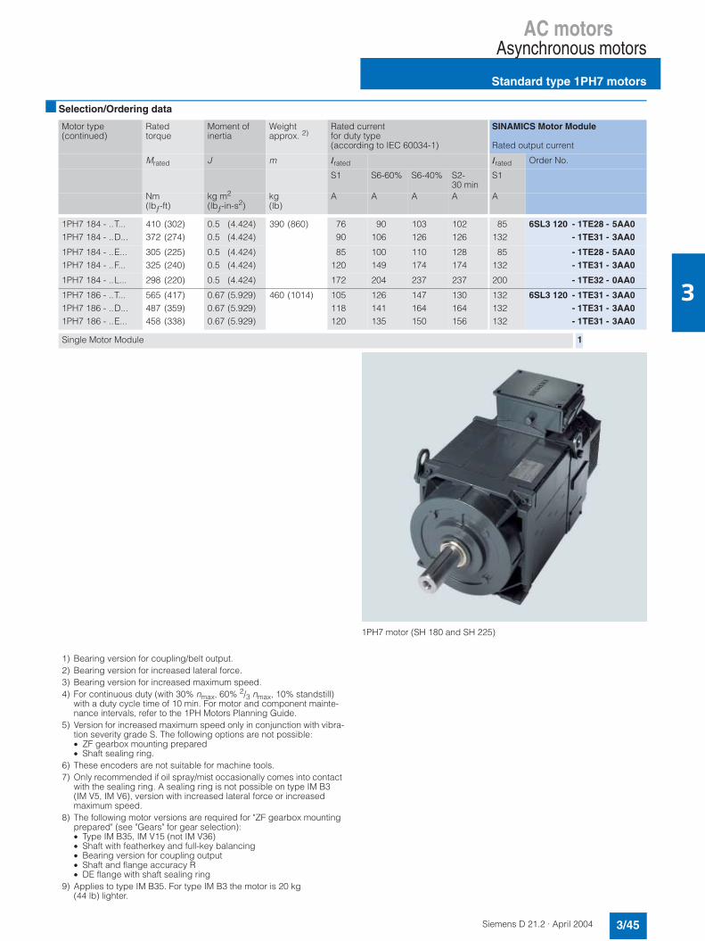
AC motorsAsynchronous motors
Standard type 1PH7 motors
3/45Siemens D 21.2 · April 2004
3
Selection/Ordering data
Motor type(continued)
Ratedtorque
Moment of inertia
Weight approx. 2)
Rated currentfor duty type (according to IEC 60034-1)
SINAMICS Motor Module
Rated output current
Mrated J m Irated Irated Order No.
S1 S6-60% S6-40% S2-30 min
S1
Nm(lbƒ-ft)
kg m2
(lbƒ-in-s2)kg(lb)
A A A A A
1PH7 184 - ..T...1PH7 184 - ..D...
410 (302)372 (274)
0.5 (4.424)0.5 (4.424)
390 (860) 76 90
90106
103126
102126
85132
6SL3 120 - 1TE28 - 5AA0- 1TE31 - 3AA0
1PH7 184 - ..E...1PH7 184 - ..F...
305 (225)325 (240)
0.5 (4.424)0.5 (4.424)
85120
100149
110174
128174
85132
- 1TE28 - 5AA0- 1TE31 - 3AA0
1PH7 184 - ..L... 298 (220) 0.5 (4.424) 172 204 237 237 200 - 1TE32 - 0AA0
1PH7 186 - ..T...1PH7 186 - ..D...1PH7 186 - ..E...
565 (417)487 (359)458 (338)
0.67 (5.929)0.67 (5.929)0.67 (5.929)
460 (1014) 105118120
126141135
147164150
130164156
132132132
6SL3 120 - 1TE31 - 3AA0- 1TE31 - 3AA0- 1TE31 - 3AA0
Single Motor Module 1
1) Bearing version for coupling/belt output.2) Bearing version for increased lateral force.3) Bearing version for increased maximum speed.4) For continuous duty (with 30% nmax, 60% 2/3 nmax, 10% standstill)
with a duty cycle time of 10 min. For motor and component mainte-nance intervals, refer to the 1PH Motors Planning Guide.
5) Version for increased maximum speed only in conjunction with vibra-tion severity grade S. The following options are not possible:• ZF gearbox mounting prepared• Shaft sealing ring.
6) These encoders are not suitable for machine tools.7) Only recommended if oil spray/mist occasionally comes into contact
with the sealing ring. A sealing ring is not possible on type IM B3(IM V5, IM V6), version with increased lateral force or increasedmaximum speed.
8) The following motor versions are required for "ZF gearbox mountingprepared" (see "Gears" for gear selection):• Type IM B35, IM V15 (not IM V36)• Shaft with featherkey and full-key balancing• Bearing version for coupling output• Shaft and flange accuracy R• DE flange with shaft sealing ring
9) Applies to type IM B35. For type IM B3 the motor is 20 kg(44 lb) lighter.
1PH7 motor (SH 180 and SH 225)

AC motorsAsynchronous motors
Standard type 1PH7 motors
3/46 Siemens D 21.2 · April 2004
3
Selection/Ordering data
ShaftheightSH
Ratedspeed
Max. permanent speed
Max. speed 4) Rated power for duty type (according to IEC 60034-1)
1PH7 asynchronous motor
nrated nS1 cont.1) nS1 cont.
2) nS1 cont. 3) nmax nmax
5) Prated Order No.Standard type
S1 S6-60% S6-40% S2-30 min
rpm rpm rpm rpm rpm rpm kW(HP)
kW(HP)
kW(HP)
kW(HP)
225 700 3100 2700 3600 4500 5500 55 (73.7) 66 (88.5) 75 (100.5) 78 (104.6) 1PH7 224 - 7 7C7 7 - 07 7 7
1000 71 (95.2) 88 (118) 105 (140.8) 114 (153) - 7 7D7 7 - 07 7 7
1500 100 (134) 126 (169) 136 (182.3) 140 (187.7) - 7 7F7 7 - 07 7 7
• Fans: External fan unit, PG cable entry in terminal boxwithout external fan unit, for pipe connection, PC cable entry in terminal boxExternal fan unit, metric cable entry in terminal boxwithout external fan unit, for pipe connection, metric cable entry in terminal box
2678
• Encoder systems for motors with-out DRIVE-CLiQ interface:
Without encoderAbsolute encoder EnDat 2048 pulses/revolutionIncremental encoder HTL 1024 pulses/revolution 6)
Incremental encoder HTL 2048 pulses/revolution 6)
Incremental encoder sin/cos 1 Vpp with C and D track 6)
Incremental encoder sin/cos 1 Vpp without C and D track2-pole resolver 6)
• Encoder systems for motors with DRIVE-CLiQ interface:
Absolute encoder EnDat 2048 pulses/revolutionIncremental encoder sin/cos 1 Vpp 2048 pulses/revolution with C and D trackIncremental encoder sin/cos 1 Vpp 2048 pulses/revolution without C and D track
FDQ
• Terminal box/cable entry:
Top/rightTop/DETop/NDETop/left
• Type of construction: IM B3IM B3 (IM V5, IM V6) (lifting concept for vertical types)IM B35 IM B35 (IM V15, IM V36) (lifting concept for vertical types)
• Bearing version for: • Vibration severity grade:
• Shaft and flange accuracy:
Coupling output Coupling output Coupling output Coupling output Belt outputBelt outputIncreased lateral force(belt output)Increased lateral force(belt output)Increased speed(coupling output) 7)
RRSSRRRR
R
S
NRRRNRN
R
R
• Shaft extension 8) (DE):FeatherkeyFeatherkeyFeatherkeyFeatherkeySmooth shaftSmooth shaft
• Balancing:Half-keyHalf-keyFull-keyFull-key––
• Direction of air flow (fan):DE → NDENDE→ DEDE → NDENDE→ DEDE → NDENDE→ DE
• Exhaust direction:RightAxialRightAxialRightAxial
• Degree of protection:IP55, fan IP54IP55, fan IP54IP55, fan IP54IP55, fan IP54IP55, fan IP54IP55, fan IP54
• Seal:–DE flange with shaft sealing ring 7)
–DE flange with shaft sealing ring 9)
–DE flange with shaft sealing ring 9)
• Color:PrimedPrimedAnthracite grayAnthracite grayAnthracite gray, two coats Anthracite gray, two coats
AEHJMNR
0123
0135
ABCDEFG
H
J
ABCDJK
023568

AC motorsAsynchronous motors
Standard type 1PH7 motors
3/47Siemens D 21.2 · April 2004
3
Selection and ordering data
Motor type(continued)
Ratedtorque
Moment of inertia
Weight approx. 2)
Rated current for duty type(according to IEC 60034-1)
SINAMICS Motor Module
Rated output current
Mrated J m Irated Irated Order No.
S1 S6-60% S6-40% S2-30 min
S1
Nm(lbƒ-ft)
kg m2
(lbƒ-in-s2)kg(lb)
A A A A A
1PH7 224 - .. C ... 750 (553) 1.48 (13.098) 650 (1433) 117 135 149 155 132 6SL3 120 - 1TE31 - 3AA0
1PH7 224 - ..D ... 678 (500) 1.48 (13.098) 650 (1433) 164 190 222 240 200 - 1TE32 - 0AA0
1PH7 224 - ..F ... 636 (469) 1.48 (13.098) 650 (1433) 188 230 248 256 200 - 1TE32 - 0AA0
Single Motor Module 1
1) Bearing version for coupling/belt output.2) Bearing version for increased lateral force.3) Bearing version for increased maximum speed.4) For continuous duty (with 30% nmax, 60% 2/3 nmax, 10% standstill)
with a duty cycle time of 10 min. For motor and component mainte-nance intervals, refer to the 1PH Motors Planning Guide.
5) Version for increased maximum speed only in conjunction with vibra-tion severity grade S. The following options are not possible:• ZF gearbox mounting prepared• Shaft sealing ring.
6) These encoders are not suitable for machine tools.7) Only recommended if oil spray/mist occasionally comes into contact
with the sealing ring. A sealing ring is not possible on type IM B3(IM V5, IM V6), version with increased lateral force or increasedmaximum speed.
8) The following motor versions are required for "ZF gearbox mountingprepared" (see "Gears" for gear selection):• Type IM B35, IM V15 (not IM V36)• Shaft with featherkey and full-key balancing• Bearing version for coupling output• Shaft and flange accuracy R• DE flange with shaft sealing ring
9) Applies to type IM B35. In type IM B3 the motor is 20 kg(44 lb) lighter.
1PH7 motor (SH 180 and SH 225)

AC motorsAsynchronous motors
1PH4 motors
3/48 Siemens D 21.2 · April 2004
3
OverviewGiven the compact design of modern machines, heat losses from electrical drives can have an adverse effect on machining accuracy. The consequential requirement for cool motors at high power densities led to the development of the water-cooled 1PH4 series motors.
Furthermore, a combination of high torque and small unit volume (low mass inertia) results in short acceleration and braking times and thus in a reduction in non-productive time.
The 1PH4 motors are robust, 4-pole squirrel-cage asynchronous motors. Power loss and noise are minimized. Due to the com-pact design of the motors, high maximum speeds can be achieved.
The motors are equipped with an encoder system for sensing the motor speed and indirect position. On machine tools, the en-coder system is capable of C-axis operation as standard. An additional encoder is therefore not required for C-axis operation.
Benefits
7 High power density due to small unit volume
7 Maximum speeds of up to 9000 rpm (option: 12000 rpm)
7 Full rated torque continuously available, even at standstill
7 Cooled flange to prevent thermal stressing of the mechanical power train
7 Low noise level
7 High degree of protection (IP65, shaft exit IP55)
7 High rotational accuracy.
Applications
• Any application in which extreme ambient conditions such as high temperature, dust, dirt or aggressive atmosphere do not permit natural ventilation.
• In processes where no thermal stress may be placed on theenvironment.
• Fully enclosed milling machines
• High-load milling spindles
• Counterspindles on turning machines
• Special machines where cooling water is available for specific processes
Please refer to "Liquid cooling" for a list of heat exchanger man-ufacturers.
Technical data
1) DE is the drive end with shaft. NDE is the non-drive end.2) For permissible loads, refer to the 1PH Motors Planning Guide.3) HTL encoders are not suitable for the C-axis machine tools.
Insulation of the stator windingin accordance with EN 60034-1(IEC 60034-1)
Temperature class F for a coolant inlet temperatureof up to +30 °C (+86 °F)
Built-in encoder systemsfor motors withoutDRIVE-CLiQ interface:
Incremental encoder sin/cos1 Vpp, 2048 pulses/revolution, absolute encoder EnDat, incre-mental encoder HTL 1024 pulses/revolution or 2048 pulses/revolu-tion 3)
Type according toEN 60034-7 (IEC 60034-7)
IM B35 (IM V15, IM V36)
Terminal box location(facing drive end) 1)
Top, rotatable 4 x 90°
Terminal box connection type• Motor• Motor encoder and PTC thermistor
Terminals in terminal box12/17-pin circular socket(without mating connector)
Bearing arrangement at drive end 2) Bearing for belt or coupling output
Vibration severity in accordance with EN 60034-14 (IEC 60034-14)
Grade R (reduced)
Shaft and flange accuracy accord-ing to DIN 42955 (IEC 60072-1)
Tolerance rated (normal)
Drive end shaft extensionaccording to DIN 748
With featherkey and keyway
Degree of protection according toEN 60034-5 (IEC 60034-5)
IP65, IP55 on shaft exit
Paint finish Anthracite gray
Permissible coolant temperature To prevent the formation of con-densation, we recommend an inlet temperature of approxi-mately +30 °C (+86 °F)(depending on ambient condi-tions).
Temperature monitoring Two KTY 84 temperature sensors in the stator winding, of which one as reserve
Sound pressure level, LpA (1 m) acc. to ISO 1680 (EN 21680) (tolerance +3 dB)
1PH4 10: 69 dB 1PH4 13: 69 dB 1PH4 16: 71 dB

AC motorsAsynchronous motors
1PH4 motors
3/49Siemens D 21.2 · April 2004
3
Characteristics
Typical power-speed diagram for AC motors 1)
The diagram shows the typical ratio between motor speed and drive power for 1PH4 motors in the following duty types (according to IEC 60034-1):
S 1: Continuous dutyS 6: Continuous duty with intermittent loading and a relative ON
period of 60% (S6-60%) or 40% (S6-40%) with a maximum duty cycle time of 10 minutes.
")%*
")"*
")%*
")"*
+
,-
'
./
+
1) For additional configuration information, refer to the 1PH Motors Planning Guide.
2) Values from the power-speed diagram based on usingan Active Line Module on a 3 AC 400 V supply system.If using a Smart Line Module, proceed in accordance with the 1PHPlanning Guide.
Motor Ratedspeed
Attainable speed for rated power in duty type(according to IEC 60034-1)
Type nrated n22)
S1 S6-60% S6-40%
rpm rpm rpm rpm
1PH4 1031PH4 1051PH4 107
150015001500
860088008600
750076007400
650065006400
1PH4 1331PH4 1351PH4 1371PH4 138
1500150015001500
8000740068007800
7400620058006600
6000550050005800
1PH4 1631PH4 1671PH4 168
150015001500
630052006300
520044005300
450038004600

AC motorsAsynchronous motors
Standard type 1PH4 motors
3/50 Siemens D 21.2 · April 2004
3
Selection/Ordering data
Options
When ordering a motor with options, "-Z" must be added to the order number and the order code stated for the specific version required.
Order codes must not be repeated in plain text.
Example: 1PH4 135-4NF26-ZK04 + K09 +L37
ShaftheightSH
Ratedspeed
Max. permanent speed
Max.speed4)
L374) 5)
Motor ratedpower for duty type (according to IEC 60034-1)
1PH4 asynchronous motor
nrated nS1 cont.1) nS1 cont.
2) nS1 cont. 3) nmax nmax Prated Order No.
Standard typeS1 S6-60% S6-40%
rpm rpm rpm rpm rpm rpm kW(HP)
kW(HP)
kW(HP)
100 1500 5600 6500 10000 9000 12000 7.5 (10.1)11 (14.7)14 (18.8)
8.75 (11.7)12.75 (17.1)16.25 (21.8)
10 (13.4)14.75 (19.8)18.75 (25.1)
1PH4 103 - 47F261PH4 105 - 47F261PH4 107 - 47F26
132 1500 5200 6000 9250 8000 10000 15 (20.1)22 (29.5)27 (36.2)30 (40.2)
18 (24.1)26.5 (35.5)32.5 (43.6)36 (48.3)
21 (28.2)31 (41.6)38 (50.9)42 (56.3)
1PH4 133 - 47F261PH4 135 - 47F261PH4 137 - 47F261PH4 138 - 47F26
160 1500 4000 4500 7000 6500 8000 37 (50)46 (61.7)52 (69.7)
45 (60.3)55 (73.7)62.5 (83.8)
52.5 (70.4)65 (87.1)73 (97.9)
1PH4 163 - 47F261PH4 167 - 47F261PH4 168 - 47F26
• Encoder systems for motors withoutDRIVE-CLiQinterface:
Absolute encoder EnDat, 2048 pulses/revolutionIncremental encoder HTL 1024 pulses/revolution 6) (on request)Incremental encoder HTL 2048 pulses/revolution 6) (on request)Incremental encoder sin/cos 1 Vpp, 2048 pulses/revolution with C and D trackIncremental encoder sin/cos 1 Vpp, 2048 pulses/revolution without C and D track
EHJMN
Bearing version/gearbox mounting• Single bearing facing drive end
(standard = twin bearing)- for coupling 7)
- for planetary gear units (e.g. ZF gearboxes 2LG43..., types IM B35, IM V15) 7)8)
- for low to moderate lateral forces
Code
K00
Vibration severity according to EN 60034-14 (IEC 60034-14) (standard = vibration severity grade R, twin bearing)• Grade S with twin bearing • Grade S with single bearing • Grade SR with single bearing
K05 9)
K02 9)
K03 9)
Shaft and flange accuracy according to DIN 42955 (IEC 60072-1)(standard = tolerance N)• Tolerance R 10) K04
Shaft extension (drive end)(standard = full-key balancing with keyway)• Smooth shaft • Half-key balancing
K42L69
Shaft seal (drive end) 11)
• Rotary shaft seal, oil-tight, IP65 K18
Brake 7)
• With holding brake mounted on drive end G46
Terminal box location(facing drive end) (standard = top)• Side right• Side left
K09K10
Rotation of terminal box about its own axis• Through 90°, cable entry from drive end• Through 90°, cable entry from non-drive end• Through 180°
K83K84K85
Speed 12)
• With increased maximum speed and half-key balancing
L37
Rating plate• Second rating plate, separately packed K31
Encoder system• Without encoder H30
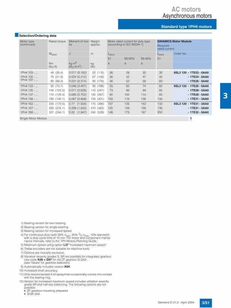
AC motorsAsynchronous motors
Standard type 1PH4 motors
3/51Siemens D 21.2 · April 2004
3
Selection/Ordering data
1) Bearing version for twin bearing.2) Bearing version for single bearing.3) Bearing version for increased speed.4) For continuous duty (with 30% nmax, 60% 2/3 nmax, 10% standstill)
with a duty cycle time of 10 min. For motor and component mainte-nance intervals, refer to the 1PH Motors Planning Guide.
5) Maximum speed using option L37 "increased maximum speed".6) These encoders are not suitable for machine tools.7) Options are mutually exclusive.8) Vibration severity grades S, SR not possible for integrated gearbox.
Use code K00 + G97 for old ZF gearbox 2LG42...(see "Gears" for gearbox selection).
9) Automatically includes version K04.10) Increased shaft accuracy.11) Only recommended if oil spray/mist occasionally comes into contact
with the sealing ring.12) Version for increased maximum speed includes vibration severity
grade SR and half-key balancing. The following options are not possible:• ZF gearbox mounting prepared• Shaft seal.
Motor type(continued)
Rated torque Moment of iner-tia
Weight approx.
Motor rated current for duty type (according to IEC 60034-1)
SINAMICS Motor ModuleRequired rated current
Mrated J m Irated Irated Order No.
S1 S6-60% S6-40% S1
Nm(lbƒ-ft)
kg m2
(lbƒ-in-s2)kg(lb)
A A A
1PH4 103 - ...1PH4 105 - ...1PH4 107 - ...
48 (35.4)70 (51.6)90 (66.4)
0.017 (0.150)0.024 (0.212)0.031 (0.274)
52 (115)67 (148)80 (176)
263846
294252
324758
304560
6SL3 120 - 1TE23 - 0AA0- 1TE24 - 5AA0- 1TE26 - 0AA0
1PH4 133 - ...1PH4 135 - ...1PH4 137 - ...1PH4 138 - ...
95 (70.1)140 (103.3)170 (125.4)190 (140.1)
0.046 (0.407)0.071 (0.628)0.085 (0.752)0.097 (0.858)
90 (198)112 (247)130 (287)150 (331)
557385
102
6586
100119
7499
114136
608585
132
6SL3 120 - 1TE26 - 0AA0- 1TE28 - 5AA0- 1TE28 - 5AA0- 1TE31 - 3AA0
1PH4 163 - ...1PH4 167 - ...1PH4 168 - ...
235 (173.3)293 (216.1)331 (244.1)
0.17 (1.504)0.206 (1.823)0.22 (1.947)
175 (386)210 (463)240 (529)
107120148
125138173
142158197
132132200
6SL3 120 - 1TE31 - 3AA0- 1TE31 - 3AA0- 1TE32 - 0AA0
Single Motor Module 1

AC motorsAsynchronous motors
1PM4 motors with hollow shaft
3/52 Siemens D 21.2 · April 2004
3
1PH7 motor (SH 100 and SH 132, liquid-cooled)
Overview
Liquid-cooled 1PM4 motors have been specially designed for direct mounting on mechanical spindles. The hollow shaft per-mits the passage of coolant for internally cooled tools.The shaft is prepared on the non-drive end of the motor forconnection of a turning bushing for input of the coolant.
Given the compact design of modern machines, heat losses from electrical drives can have an adverse effect on machining accuracy. The consequential requirement for cool motors at high power densities led to the development of the liquid-cooled 1PM4 motors.
Furthermore, a combination of high torque and small unit volume (low mass inertia) results in short acceleration and braking times and thus in a reduction in non-productive time.
The motors have a built-in hollow shaft measuring system for sensing the motor speed and indirect position.
Benefits7 Hollow shaft for passage of coolant with direct spindle
mounting
7 Maximum speeds up to 12000 rpm
7 Full rated torque continuously available, even at standstill
7 Cooled flange to prevent thermal stressing of the mechanical power train
7 Low noise level
7 High rotational accuracy
7 Short ramp-up and braking times.
Applications
• Compact machining centers
• Directly driven tools with internal cooling
• Special machines
Please refer to "Liquid cooling" for a list of heat exchanger manufacturers.
Technical data
1) For types, see "Selection guide".
Insulation of the stator winding in accordance with EN 60034-1 (IEC 60034-1)
Temperature class F for a coolant inlet temperature of up to +30 °C (+86 °F)
Built-in encoder systemsfor motors withoutDRIVE-CLiQ interface
Incremental encoder sin/cos1 Vpp, 256 pulses/revolution
Type according to EN 60034-71)
(IEC 60034-7)IM B35 (IM V15, IM V36)
Terminal box location(facing drive end)
Top, rotatable 4 x 90°
Terminal box connection type• Motor• Motor encoder and PTC thermistor
Terminals in terminal box17-pin circular socket(without mating connector)
Vibration severity in accordance with EN 60034-14 (IEC 60034-14)
Stage SR
Shaft and flange accuracy accord-ing to DIN 42955 (IEC 60072-1)
Tolerance R (reduced)
Drive end shaft extension With smooth shaft,without keyway
Hollow ID for shaft ∅ 11.5 mm (0.45 in)
Degree of protection according toEN 60034-5 (IEC 60034-5)
IP65, IP55 on shaft exit
Paint finish Anthracite gray
Permissible coolant temperature To prevent the formation of con-densation, we recommend a cool-ant inlet temperature of approximately +30 °C (+86 °F).
Temperature monitoring Two KTY 84 temperature sensorsin the stator winding, of which one as reserve
Sound pressure LpA (1 m) acc. toEN ISO 1680 (tolerance +3 dB)
1PM4 10.: 69 dB1PM4 13.: 69 dB

AC motorsAsynchronous motors
1PM6 motors with hollow shaft
3/53Siemens D 21.2 · April 2004
3
1PM6 motor (SH 100 and SH 132 with radial and axial fans)
OverviewAir-cooled 1PM6 motors have been specially designed for direct mounting on mechanical spindles. The hollow shaft permits the passage of coolant for internally cooled tools.The shaft is prepared on the non-drive end of the motor forconnection of a turning bushing for input of the coolant.
The 1PM6 motors are rugged and maintenance-free 4-pole squirrel-cage asynchronous motors. They have been designed specifically for use in conjunction with the SINAMICS S drive system.
A fan for providing separate ventilation is mounted either radially or axially on the rear of the motor. The direction of air flow is from the drive end to the non-drive end in order to keep the exhaust heat of the motor away from the machine tool.
The motors have a built-in hollow shaft measuring system for sensing the motor speed and indirect position.
Benefits7 Hollow shaft for passage of coolant with direct spindle
mounting
7 Maximum speeds up to 12000 rpm
7 Full rated torque continuously available, even at standstill
7 Axial or radial fans
7 High rotational accuracy
7 Short ramp-up and braking times.
1) For type, see "Selection guide".
Applications
• Compact machining centers
• Directly driven tools with internal cooling
• Special machines.
Technical data
Insulation of the stator winding in accordance with EN 60034-1 (IEC 60034-1)
Temperature class Ffor a coolant inlet temperatureof up to +40 °C (+104 °F)
Motor fan ratings 3 AC 400 V 50/60 Hz
Built-in encoder systemsfor motors withoutDRIVE-CLiQ interface
Incremental encoder sin/cos1 Vpp, 256 pulses/revolution
Type according to EN 60034-7 1)
(IEC 60034-7)IM B5 (IM V1, IM V3)
Terminal box location(facing drive end)
With axial fan:Top, rotatable 4 x 90°With radial fan:Side right, rotatable 4 x 90°
Terminal box connection type• Motor• Fans• Motor encoder and PTC thermistor
Terminals in terminal boxTerminals in terminal box17-pin circular socket(without mating connector)
Vibration severity in accordance with EN 60034-14 (IEC 60034-14)
Stage SR
Shaft and flange accuracy accord-ing to DIN 42955 (IEC 60072-1)
Tolerance R (reduced)
Drive end shaft extension With smooth shaft,without keyway
Hollow ID for shaft ∅ 11.5 mm (0.45 in)
Degree of protection according toEN 60034-5 (IEC 60034-5)
IP55, fan IP54
Paint finish Anthracite gray
Permissible coolant temperature -15 °C to +40 °C(+5 °F to +104 °F)
Temperature monitoring Two KTY 84 temperature sensorsin the stator winding, of wich one as reserve
Sound pressure LpA (1 m) acc. to EN ISO 1680(tolerance +3 dB)
From DE to NDE(with the fan operating on a 50 Hz supply system)1PM6 10.: 70 dB1PM6 13.: 70 dB
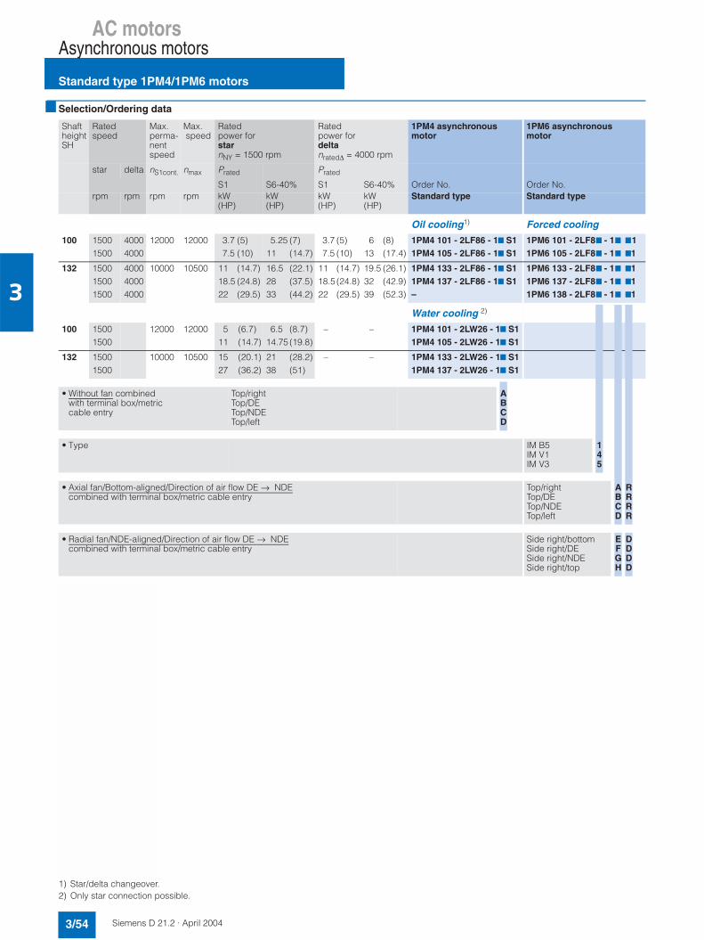
AC motorsAsynchronous motors
Standard type 1PM4/1PM6 motors
3/54 Siemens D 21.2 · April 2004
3
Selection/Ordering data
1) Star/delta changeover.2) Only star connection possible.
ShaftheightSH
Ratedspeed
Max.perma-nentspeed
Max.speed
Ratedpower forstarnNY = 1500 rpm
Ratedpower fordeltanrated∆ = 4000 rpm
1PM4 asynchronous motor
1PM6 asynchronous motor
star delta nS1cont. nmax Prated Prated
S1 S6-40% S1 S6-40% Order No. Order No.rpm rpm rpm rpm kW
(HP)kW(HP)
kW(HP)
kW(HP)
Standard type Standard type
Oil cooling1) Forced cooling
100 15001500
40004000
12000 12000 3.7 (5)7.5 (10)
5.25 (7)11 (14.7)
3.7 (5)7.5 (10)
6 (8)13 (17.4)
1PM4 101 - 2LF86 - 17 S11PM4 105 - 2LF86 - 17 S1
1PM6 101 - 2LF87 - 17 711PM6 105 - 2LF87 - 17 71
132 150015001500
400040004000
10000 10500 11 (14.7)18.5 (24.8)22 (29.5)
16.5 (22.1)28 (37.5)33 (44.2)
11 (14.7)18.5 (24.8)22 (29.5)
19.5 (26.1)32 (42.9)39 (52.3)
1PM4 133 - 2LF86 - 17 S11PM4 137 - 2LF86 - 17 S1–
1PM6 133 - 2LF87 - 17 711PM6 137 - 2LF87 - 17 711PM6 138 - 2LF87 - 17 71
Water cooling 2)
100 15001500
12000 12000 5 (6.7)11 (14.7)
6.5 (8.7)14.75 (19.8)
– – 1PM4 101 - 2LW26 - 17 S11PM4 105 - 2LW26 - 17 S1
132 15001500
10000 10500 15 (20.1)27 (36.2)
21 (28.2)38 (51)
– – 1PM4 133 - 2LW26 - 17 S11PM4 137 - 2LW26 - 17 S1
• Without fan combined with terminal box/metriccable entry
Top/rightTop/DETop/NDETop/left
ABCD
• Type IM B5IM V1IM V3
145
• Axial fan/Bottom-aligned/Direction of air flow DE → NDEcombined with terminal box/metric cable entry
Top/rightTop/DETop/NDETop/left
ABCD
RRRR
• Radial fan/NDE-aligned/Direction of air flow DE → NDEcombined with terminal box/metric cable entry
Side right/bottomSide right/DESide right/NDESide right/top
EFGH
DDDD
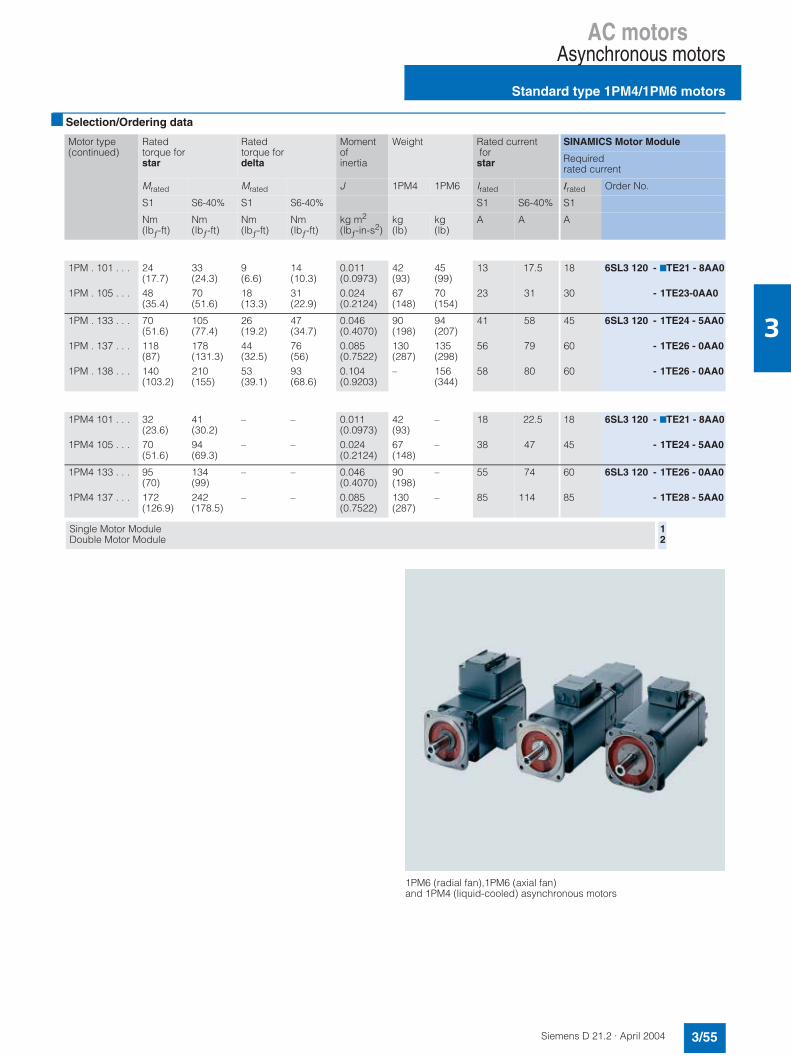
AC motorsAsynchronous motors
Standard type 1PM4/1PM6 motors
3/55Siemens D 21.2 · April 2004
3
Selection/Ordering data
Motor type(continued)
Ratedtorque forstar
Ratedtorque fordelta
Momentofinertia
Weight Rated current for star
SINAMICS Motor Module
Required rated current
Mrated Mrated J 1PM4 1PM6 Irated Irated Order No.
S1 S6-40% S1 S6-40% S1 S6-40% S1
Nm(lbƒ-ft)
Nm(lbƒ-ft)
Nm(lbƒ-ft)
Nm(lbƒ-ft)
kg m2
(lbƒ-in-s2)kg(lb)
kg(lb)
A A A
1PM . 101 . . .
1PM . 105 . . .
24(17.7)48(35.4)
33(24.3)70(51.6)
9(6.6)18(13.3)
14(10.3)31(22.9)
0.011(0.0973)0.024(0.2124)
42(93)67(148)
45(99)70(154)
13
23
17.5
31
18
30
6SL3 120 - 7TE21 - 8AA0
- 1TE23-0AA0
1PM . 133 . . .
1PM . 137 . . .
1PM . 138 . . .
70(51.6)118(87)140(103.2)
105(77.4)178(131.3)210(155)
26(19.2)44(32.5)53(39.1)
47(34.7)76(56)93(68.6)
0.046(0.4070)0.085(0.7522)0.104(0.9203)
90(198)130(287)–
94(207)135(298)156(344)
41
56
58
58
79
80
45
60
60
6SL3 120 - 1TE24 - 5AA0
- 1TE26 - 0AA0
- 1TE26 - 0AA0
1PM4 101 . . .
1PM4 105 . . .
32(23.6)70(51.6)
41(30.2)94(69.3)
–
–
–
–
0.011(0.0973)0.024(0.2124)
42(93)67(148)
–
–
18
38
22.5
47
18
45
6SL3 120 - 7TE21 - 8AA0
- 1TE24 - 5AA0
1PM4 133 . . .
1PM4 137 . . .
95(70)172(126.9)
134(99)242(178.5)
–
–
–
–
0.046(0.4070)0.085(0.7522)
90(198)130(287)
–
–
55
85
74
114
60
85
6SL3 120 - 1TE26 - 0AA0
- 1TE28 - 5AA0
Single Motor ModuleDouble Motor Module
12
1PM6 (radial fan),1PM6 (axial fan) and 1PM4 (liquid-cooled) asynchronous motors

AC motorsAsynchronous motors
1PM4/1PM6 motors
3/56 Siemens D 21.2 · April 2004
3
Characteristics
Typical power-speed diagram for 1PM4 star/delta changeover motors 1)
oil-cooled and 1PM6 motors 1)
Typical power-speed diagram for 1PM4 motors 1) water-cooled
The diagrams show the typical ratio between motor speed and drive power for 1PM4/1PM6 motors in the following duty types (according to IEC 60034-1):
S1: Continuous duty
S6-40%: Continuous duty with intermittent loading and a relative ON period of 40% (S6-40%) with a maximum duty cycle time of 10 minutes.
1) For additional information, refer to the 1PM Motors Planning Guide. 2) Values from the power-speed diagram based on using an Active Line
Module on a 3 AC 400 V supply system. If using the Smart Line Module, proceed in accordance with the 1PM Planning Guide.
((
")%*((")%*((
,-((
,-((
'&
((
+0+ +
")%*
")%*
./+
Ratedspeed
Attainablespeed for rated power in duty type (according to IEC 60034-1)
Ratedspeed
Attainablespeed for rated power in duty type (according to IEC 60034-1)
Motortype
Star circuit Delta circuit
nratedY n22) nrated∆ n2
2)
S1 S6-40% S1 S6-40%
rpm rpm rpm rpm rpm rpm
Forced cooling
1PM6 101 1500 9710 7170 4000 12000 12000
1PM6 1051PM6 133
15001500
90008000
63608140
40004000
1200010500
1200010500
1PM6 1371PM6 138
15001500
70004000
59204000
40004000
105006000
105006500
Oil cooling
1PM4 101 1500 9710 7170 4000 12000 12000
1PM4 1051PM4 133
15001500
90008000
63608140
40004000
1200010500
1200010500
1PM4 137 1500 7000 5920 4000 10500 10500
Water cooling
1PM4 101 1500 9670 7590 – – –
1PM4 1051PM4 133
15001500
94608290
71306130
– – –
1PM4 137 1500 6860 4920 – – –
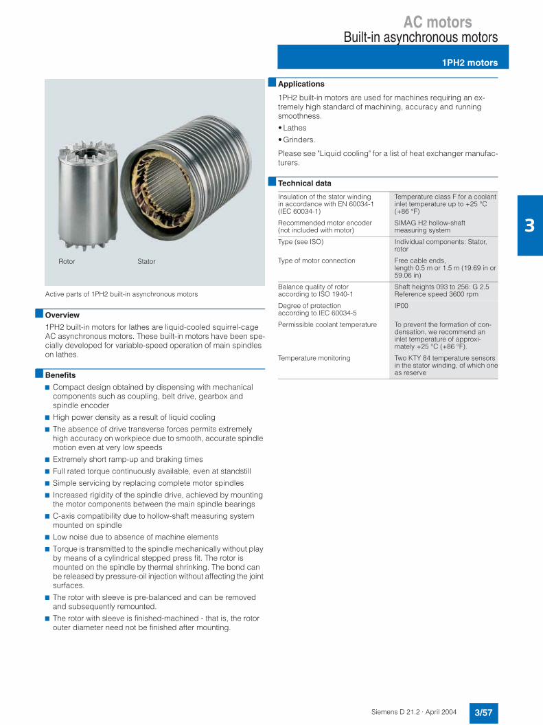
AC motorsBuilt-in asynchronous motors
1PH2 motors
3/57Siemens D 21.2 · April 2004
3
Active parts of 1PH2 built-in asynchronous motors
Overview
1PH2 built-in motors for lathes are liquid-cooled squirrel-cage AC asynchronous motors. These built-in motors have been spe-cially developed for variable-speed operation of main spindles on lathes.
Benefits
7 Compact design obtained by dispensing with mechanical components such as coupling, belt drive, gearbox and spindle encoder
7 High power density as a result of liquid cooling
7 The absence of drive transverse forces permits extremely high accuracy on workpiece due to smooth, accurate spindle motion even at very low speeds
7 Extremely short ramp-up and braking times
7 Full rated torque continuously available, even at standstill
7 Simple servicing by replacing complete motor spindles
7 Increased rigidity of the spindle drive, achieved by mounting the motor components between the main spindle bearings
7 C-axis compatibility due to hollow-shaft measuring systemmounted on spindle
7 Low noise due to absence of machine elements
7 Torque is transmitted to the spindle mechanically without play by means of a cylindrical stepped press fit. The rotor is mounted on the spindle by thermal shrinking. The bond can be released by pressure-oil injection without affecting the joint surfaces.
7 The rotor with sleeve is pre-balanced and can be removed and subsequently remounted.
7 The rotor with sleeve is finished-machined - that is, the rotor outer diameter need not be finished after mounting.
Rotor Stator
Applications
1PH2 built-in motors are used for machines requiring an ex-tremely high standard of machining, accuracy and runningsmoothness.
• Lathes
• Grinders.
Please see "Liquid cooling" for a list of heat exchanger manufac-turers.
Technical data
Insulation of the stator winding in accordance with EN 60034-1(IEC 60034-1)
Temperature class F for a coolantinlet temperature up to +25 °C (+86 °F)
Recommended motor encoder(not included with motor)
SIMAG H2 hollow-shaft measuring system
Type (see ISO) Individual components: Stator,rotor
Type of motor connection Free cable ends, length 0.5 m or 1.5 m (19.69 in or 59.06 in)
Balance quality of rotor according to ISO 1940-1
Shaft heights 093 to 256: G 2.5 Reference speed 3600 rpm
Degree of protectionaccording to IEC 60034-5
IP00
Permissible coolant temperature To prevent the formation of con-densation, we recommend an inlet temperature of approxi-mately +25 °C (+86 °F).
Temperature monitoring Two KTY 84 temperature sensors in the stator winding, of which oneas reserve

AC motorsBuilt-in asynchronous motors
Standard type 1PH2 motors
3/58 Siemens D 21.2 · April 2004
3
Selection/Ordering data
Characteristics
Typical power-speed diagram for AC motors 3)
The diagram shows the typical ratio between motor speed and drive power for 1PH2 motors in the following duty types (accord-ing to IEC 60034-1):
S 1: Continuous dutyS 6: Continuous duty with intermittent loading and a relative ON
period of 60% (S6-60%) or 40% (S6-40%) with a maximum duty cycle time of 10 minutes.
1) Data given for ∆T = 70 K, unless otherwise stated.2) Version available on request.3) For additional configuration information, refer to the 1PH Motors
Planning Guide.4) Values from the power-speed diagram based on using an Active Line
Module on a 3 AC 400 V supply system.If using a Smart Line Module, proceed in accordance with the 1PH Plan-ning Guide.
Ratedspeed
Max.speed
Motor rated power for duty type (according to IEC 60034-1) 1)
1PH2 asynchronous built-in motor
Rated torque 1)
nrated nmax Prated Mrated
S1 S1∆T=105 K
S6-60% S6-40% Order No.Standard type
∆T=105 K
rpm rpm kW(HP)
kW(HP)
kW(HP)
kW(HP)
Nm(lbƒ-ft)
Nm(lbƒ-ft)
1500 10000 7.5 (10)10.1 (13.5)
9.4 (12.6)13 (17.4)
8.2 (11)11 (14.7)
9 (12.1)12 (16.1)
1PH2 093 - 6WF4 71PH2 095 - 6WF4 7
48 64
(35.4)(47.2)
60 83
(44.2)(61.2)
1500 10000 15.1 (20.2)16.5 (22.1)18.1 (24.3)23.6 (31.6)
18.5 (24.8)21.5 (28.8)23.7 (31.8)30.9 (41.4)
17 (22.8)18.5 (24.8)20.5 (27.5)26.0 (34.9)
19 (25.5)21 (28.2)23 (30.8)29.5 (39.5)
1PH2 113 - 6WF4 71PH2 115 - 6WF4 71PH2 117 - 6WF4 71PH2 118 - 6WF4 7
95105115146
(70.1)(77.4)(84.8)(107.7)
118137151197
(87)(101)(111.4)(145.3)
750 600 500 500
8000 8000 6000 6000
11.8 2) (15.8)14.5 2) (19.4)18.3 (24.5)23.6 (31.6)
14.4 (19.3)17.7 (23.7)22.4 (30)28.8 (38.6)
14.8 (19.8)18.1 (24.3)21.8 (29.2)29 (38.9)
17.7 (23.7)22 (29.5)25.8 (34.6)33 (44.2)
1PH2 182 - 6WC4 11PH2 184 - 6WP4 11PH2 186 - 6WB4 11PH2 188 - 6WB4 1
150230350450
(110.6)(169.6)(258.2)(332)
183281428551
(135)(207.3)(315.7)(406.4)
500 6000 4000
28.8 2) (38.6)39.3 2) (52.7)
35.3 (47.3)48.1 (64.5)
36 (48.3)48.8 (65.4)
40.6 (54.4)55 (73.7)
1PH2 254 - 6WB4 11PH2 256 - 6WB4 1
550750
(405.7)(553)
673918
(496.4)(677.1)
Free cable ends• Length: 1.5 m (59.06 in)• Length: 0.5 m (19.69 in)
(preferred type)
12
")%*
")"*
")%*
")"*
+
,-
'
./
+
Motor Ratedspeed
Attainable speed for rated power induty type(according to IEC 60034-1)
Type nrated n24)
rpmS1rpm
S6-60%rpm
S6-40%rpm
1PH2 0931PH2 095
15001500
4700 4000
4200 3600
3900 3300
1PH2 1131PH2 1151PH2 1171PH2 118
1500150015001500
5400 4500 4700 5300
4800 4100 4200 4700
4400 3700 3800 4300
1PH2 1821PH2 1841PH2 1861PH2 188
750 600 500 500
4700 7000 5000 4400
3700 5500 3500 3600
3200 4500 3000 3100
1PH2 2541PH2 256
500 500
6000 3700
5000 2900
4500 2600

AC motorsBuilt-in asynchronous motors
Standard type 1PH2 motors
3/59Siemens D 21.2 · April 2004
3
Selection/Ordering data
Motor type(continued)
Moment of inertiaof rotor
Weight (rotorand stator)approx.
Motor rated power for duty type(according to IEC 60034-1) 1)
SINAMICS Motor Module
Required rated current
J Irated Irated Order No.
S1 S6-60% S6-40% S1
kg m2
(lbƒ-in-s2)kg(lb)
A A A A
1PH2 093 - 6W...1PH2 095 - 6W...
0.028 (0.2478)0.036 (0.3186)
33 (73)42 (93)
24 30
26 32
28 34
3030
6SL3 120 - 1TE23 - 0AA0- 1TE23 - 0AA0
1PH2 113 - 6W...1PH2 115 - 6W...1PH2 117 - 6W...1PH2 118 - 6W...
0.066 (0.5841)0.073 (0.6460)0.079 (0.6991)0.100 (0.8850)
51 (112)56 (123)62 (137)78 (172)
56 55 60 82
61 60 67 90
67 66 74100
60606085
6SL3 120 - 1TE26 - 0AA0- 1TE26 - 0AA0- 1TE26 - 0AA0- 1TE28 - 5AA0
1PH2 182 - 6W...1PH2 184 - 6W...1PH2 186 - 6W...1PH2 188 - 6W...
0.207 (1.8319)0.302 (2.6726)0.440 (3.8939)0.552 (4.8851)
98 (216)135 (298)191 (421)237 (523)
37 56 65 78
44 68 77 92
52 80 87103
45608585
6SL3 120 - 1TE24 - 5AA0- 1TE26 - 0AA0- 1TE28 - 5AA0- 1TE28 - 5AA0
1PH2 254 - 6W...1PH2 256 - 6W...
1.178 (10.4251)1.623 (14.3633)
259 (571)343 (756)
117119
141143
161158
132132
6SL3 120 -1TE31 - 3AA0-1TE31 - 3AA0
Single Motor Module 1
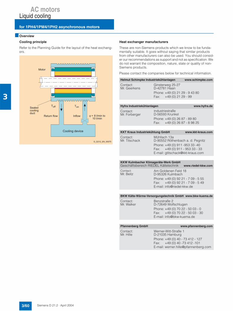
AC motorsLiquid cooling
for 1PH4/1PM4/1PH2 asynchronous motors
3/60 Siemens D 21.2 · April 2004
3
Overview
Cooling principle
Refer to the Planning Guide for the layout of the heat exchang-ers.
Heat exchanger manufacturers
These are non-Siemens products which we know to be funda-mentally suitable. It goes without saying that similar products from other manufacturers can also be used. You should consid-er our recommendations as support and not as specification. We do not warrant the composition, nature, state or quality of non-Siemens products.
Please contact the companies below for technical information.
12 2 33
22
4-+5(
+(-+(
'
6
Helmut Schimpke Industriekühlanlagen www.schimpke.com
Contact:Mr. Geerkens
Ginsterweg 25-27D-42781 HaanPhone: +49 (0) 21 29 - 9 43 80Fax: +49 (0) 21 29 - 99
Hyfra Industriekühlanlagen www.hyfra.de
Contact:Mr. Forberger
IndustriestraßeD-56593 KrunkelPhone: +49 (0) 26 87 - 89 80Fax: +49 (0) 26 87 - 8 98 25
KKT Kraus Industriekühlung GmbH www.kkt-kraus.com
Contact:Mr. Titschack
Mühllach 13aD-90552 Röthenbach a. d. PegnitzPhone: +49 (0) 911 -953 33 -40Fax: +49 (0) 911 - 953 33 - 33E-mail: [email protected]
KKW Kulmbacher Klimageräte-Werk GmbHGeschäftsbereich RIEDEL Kältetechnik www.riedel-kkw.com
Contact:Mr. Beitz
Am Goldenen Feld 18D-95326 KulmbachPhone: +49 (0) 92 21 - 7 09 - 5 55Fax: +49 (0) 92 21 - 7 09 - 5 49E-mail: [email protected]
BKW Kälte-Wärme-Versorgungstechnik GmbH www.bkw-kuema.de
Contact:Mr. Walker
Benzstraße 2D-72649 WolfschlugenPhone: +49 (0) 70 22 - 50 03 - 0Fax: +49 (0) 70 22 - 50 03 - 30E-mail: [email protected]
Pfannenberg GmbH www.pfannenberg.com
Contact:Mr. Hille
Werner-Witt-Straße 1D-21035 HamburgPhone: +49 (0) 40 - 73 412 - 127Fax: +49 (0) 40 -73 412 -101E-mail: [email protected]
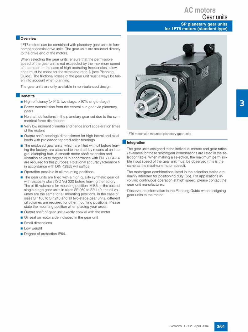
AC motorsGear units
SP planetary gear unitsfor 1FT6 motors (standard type)
3/61Siemens D 21.2 · April 2004
3
Overview
1FT6 motors can be combined with planetary gear units to form compact coaxial drive units. The gear units are mounted directly to the drive end of the motors.
When selecting the gear units, ensure that the permissible speed of the gear unit is not exceeded by the maximum speed of the motor. In the case of high operating frequencies, allow-ance must be made for the withstand ratio f2 (see Planning Guide). The frictional losses of the gear unit must always be tak-en into account when planning.
The gear units are only available in non-balanced design.
Benefits
7 High efficiency (>94% two-stage, >97% single-stage)
7 Power transmission from the central sun gear via planetary gears
7 No shaft deflections in the planetary gear set due to the sym-metrical force distribution
7 Very low moment of inertia and hence short acceleration times of the motors
7 Output shaft bearings dimensioned for high lateral and axial loads with preloaded tapered-roller bearings
7 The enclosed gear units, which are filled with oil before leav-ing the factory, are attached to the shaft by means of an inte-gral clamping hub. A smooth motor shaft extension and vibration severity degree N in accordance with EN 60034-14 are required for this purpose. Rotational accuracy tolerance N in accordance with DIN 42955 will suffice.
7 Operation possible in all mounting positions.
7 The gear units are filled with a high quality synthetic gear oil with viscosity class ISO VG 220 before leaving the factory.The oil fill volume is for mounting position IM B5. In the case of single-stage gear units in sizes SP 060 to SP 140, the oil vol-umes are the same for all mounting positions. In the case of sizes SP 180 to SP 240 and all two-stage gear units, different oil volumes are required for other mounting positions. Pleasestate the mounting position when placing your order.
7 Output shaft of gear unit exactly coaxial with the motor
7 Oil seal on motor side included in the gear unit
7 Small dimensions
7 Low weight
7 Degree of protection IP64.
1FT6 motor with mounted planetary gear units
Integration
The gear units assigned to the individual motors and gear ratios i available for these motor/gear combinations are listed in the se-lection table. When making a selection, the maximum permissi-ble input speed of the gear unit must be observed (this is the same as the maximum motor speed).
The motor/gear combinations listed in the selection tables are mainly intended for positioning duty (S5). For applications in-volving continuous operation at high speed, please contact the gear unit manufacturer.
Observe the information in the Planning Guide when assigning gear units to the motor.
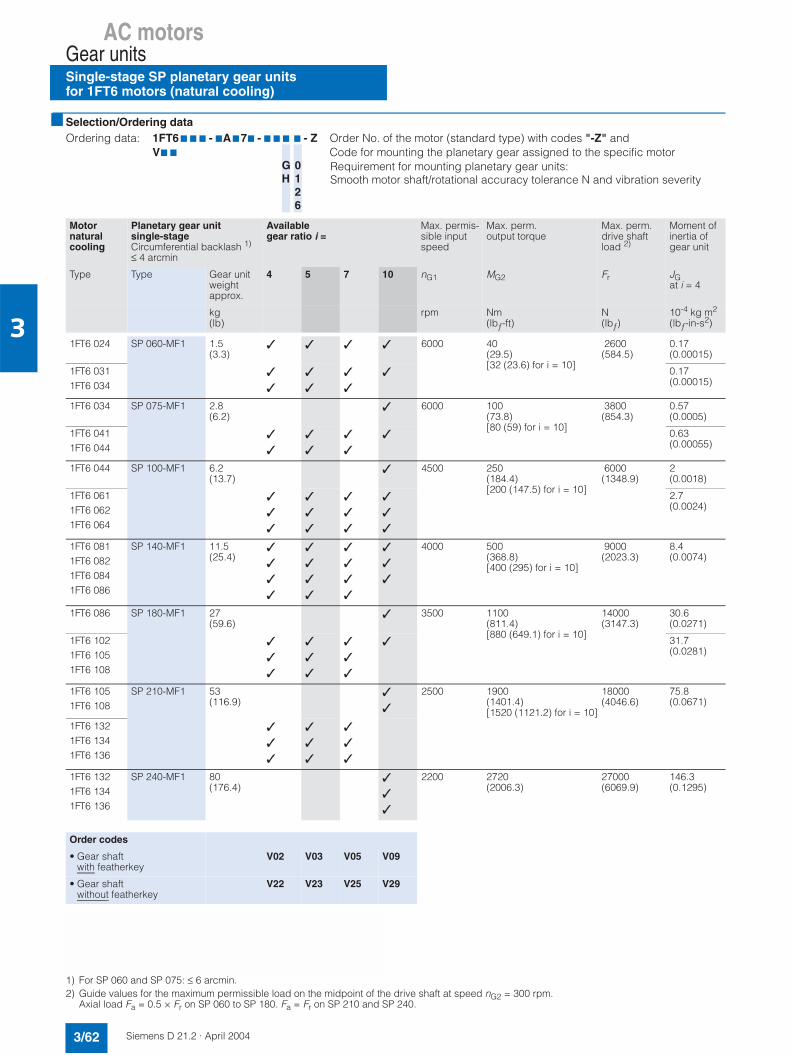
AC motorsGear unitsSingle-stage SP planetary gear units for 1FT6 motors (natural cooling)
3/62 Siemens D 21.2 · April 2004
3
Selection/Ordering data
1) For SP 060 and SP 075: ≤ 6 arcmin.2) Guide values for the maximum permissible load on the midpoint of the drive shaft at speed nG2 = 300 rpm.
Axial load Fa = 0.5 × Fr on SP 060 to SP 180. Fa = Fr on SP 210 and SP 240.
Ordering data: 1FT6 7 7 7 - 7A777 - 7 7 7 7 - Z Order No. of the motor (standard type) with codes "-Z" andV7 7 Code for mounting the planetary gear assigned to the specific motor
0126
Requirement for mounting planetary gear units: Smooth motor shaft/rotational accuracy tolerance N and vibration severity
GH
Motornaturalcooling
Planetary gear unitsingle-stageCircumferential backlash 1)
≤ 4 arcmin
Available gear ratio i =
Max. permis-sible input speed
Max. perm.output torque
Max. perm. drive shaftload 2)
Moment of inertia of gear unit
Type Type Gear unit weight approx.
4 5 7 10 nG1 MG2 Fr JGat i = 4
kg(lb)
rpm Nm(lbƒ-ft)
N(lbƒ)
10-4 kg m2
(lbƒ-in-s2)
1FT6 024 SP 060-MF1 1.5(3.3)
6000 40(29.5)[32 (23.6) for i = 10]
2600(584.5)
0.17(0.00015)
1FT6 0311FT6 034
0.17(0.00015)
1FT6 034 SP 075-MF1 2.8(6.2)
6000 100(73.8)[80 (59) for i = 10]
3800(854.3)
0.57(0.0005)
1FT6 0411FT6 044
0.63(0.00055)
1FT6 044 SP 100-MF1 6.2(13.7)
4500 250(184.4)[200 (147.5) for i = 10]
6000(1348.9)
2(0.0018)
1FT6 0611FT6 0621FT6 064
2.7(0.0024)
1FT6 0811FT6 0821FT6 0841FT6 086
SP 140-MF1 11.5(25.4)
4000 500(368.8)[400 (295) for i = 10]
9000(2023.3)
8.4(0.0074)
1FT6 086 SP 180-MF1 27(59.6)
3500 1100(811.4)[880 (649.1) for i = 10]
14000(3147.3)
30.6(0.0271)
1FT6 102 1FT6 105 1FT6 108
31.7(0.0281)
1FT6 105 1FT6 108
SP 210-MF1 53(116.9)
2500 1900(1401.4)[1520 (1121.2) for i = 10]
18000(4046.6)
75.8(0.0671)
1FT6 132 1FT6 134 1FT6 136
1FT6 132 1FT6 134 1FT6 136
SP 240-MF1 80(176.4)
2200 2720(2006.3)
27000(6069.9)
146.3(0.1295)
Order codes
• Gear shaftwith featherkey
V02 V03 V05 V09
• Gear shaftwithout featherkey
V22 V23 V25 V29
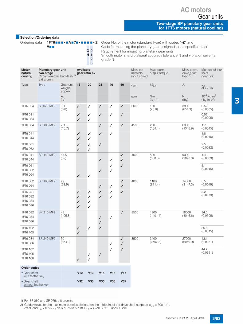
AC motorsGear units
Two-stage SP planetary gear unitsfor 1FT6 motors (natural cooling)
3/63Siemens D 21.2 · April 2004
3
Selection/Ordering data
1) For SP 060 and SP 075: ≤ 8 arcmin.2) Guide values for the maximum permissible load on the midpoint of the drive shaft at speed nG2 = 300 rpm.
Axial load Fa = 0.5 × Fr on SP 075 to SP 180. Fa = Fr on SP 210 and SP 240.
Ordering data 1FT6 7 7 7 - 7A777 - 7 7 7 7 - Z Order No. of the motor (standard type) with codes "-Z" andV7 7 Code for mounting the planetary gear assigned to the specific motor
GH
0126
Requirement for mounting planetary gear units: Smooth motor shaft/rotational accuracy tolerance N and vibration severity grade N
Motornaturalcooling
Planetary gear unittwo-stageCircumferential backlash 1)
≤ 6 arcmin
Available gear ratio i =
Max. per-missible input speed
Max. perm. output torque
Max. perm.drive shaft load 2)
Moment of iner-tia of gear unit
Type Type Gear unit weightapprox.
16 20 28 40 50 nG1 MG2 Fr JGat i = 16
kg(lb)
rpm Nm(lbƒ-ft)
N(lbƒ)
10-4 kg m2
(lbƒ-in-s2)
1FT6 024 SP 075-MF2 3.1(6.8)
6000 100(73.8)
3800(854.3)
0.52(0.0005)
1FT6 0311FT6 034
0.52(0.0005)
1FT6 034 SP 100-MF2 7.1(15.7)
4500 250(184.4)
6000(1348.9)
1.7(0.0015)
1FT6 0411FT6 044
1.8(0.0016)
1FT6 0611FT6 062
2.5(0.0022)
1FT6 0411FT6 044
SP 140-MF2 14.5(32)
4000 500(368.8)
9000(2023.3)
4.4(0.0039)
1FT6 0611FT6 0621FT6 064
5.1(0.0045)
1FT6 0621FT6 064
SP 180-MF2 29(63.9)
4000 1100(811.4)
14000(3147.3)
5.5(0.0049)
1FT6 0811FT6 0821FT6 0841FT6 086
8.2(0.0073)
1FT6 0821FT6 0841FT6 086
SP 210-MF2 48(105.8)
3500 1900(1401.4)
18000(4046.6)
34.5(0.0305)
1FT6 102 1FT6 105
35.6(0.0315)
1FT6 0841FT6 086
SP 240-MF2 70(154.3)
3500 3400(2507.8)
27000(6069.9)
43.1(0.0381)
1FT6 102 1FT6 105 1FT6 108
44.2(0.0391)
Order codes
• Gear shaftwith featherkey
V12 V13 V15 V16 V17
• Gear shaftwithout featherkey
V32 V33 V35 V36 V37
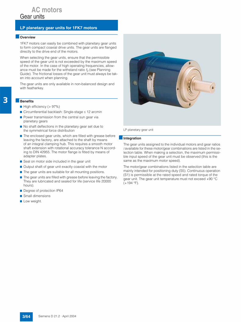
AC motorsGear units
LP planetary gear units for 1FK7 motors
3/64 Siemens D 21.2 · April 2004
3
Overview
1FK7 motors can easily be combined with planetary gear units to form compact coaxial drive units. The gear units are flanged directly to the drive end of the motors.
When selecting the gear units, ensure that the permissible speed of the gear unit is not exceeded by the maximum speed of the motor. In the case of high operating frequencies, allow-ance must be made for the withstand ratio f2 (see Planning Guide). The frictional losses of the gear unit must always be tak-en into account when planning.
The gear units are only available in non-balanced design and with featherkey.
Benefits
7 High efficiency (> 97%)
7 Circumferential backlash: Single-stage ≤ 12 arcmin
7 Power transmission from the central sun gear viaplanetary gears
7 No shaft deflections in the planetary gear set due to the symmetrical force distribution
7 The enclosed gear units, which are filled with grease before leaving the factory, are attached to the shaft by means of an integral clamping hub. This requires a smooth motor shaft extension with rotational accuracy tolerance N accord-ing to DIN 42955. The motor flange is fitted by means of adapter plates.
7 Seal on motor side included in the gear unit
7 Output shaft of gear unit exactly coaxial with the motor
7 The gear units are suitable for all mounting positions.
7 The gear units are filled with grease before leaving the factory.They are lubricated and sealed for life (service life 20000 hours).
7 Degree of protection IP64
7 Small dimensions
7 Low weight.
LP planetary gear unit
Integration
The gear units assigned to the individual motors and gear ratios i available for these motor/gear combinations are listed in the se-lection table. When making a selection, the maximum permissi-ble input speed of the gear unit must be observed (this is the same as the maximum motor speed).
The motor/gear combinations listed in the selection table are mainly intended for positioning duty (S5). Continuous operation (S1) is permissible at the rated speed and rated torque of the gear unit. The gear unit temperature must not exceed +90 °C (+194 °F).

AC motorsGear units
LP planetary gear units for 1FK7 motors
3/65Siemens D 21.2 · April 2004
3
Selection/Ordering data
Continuous duty S1Continuous operation is permissible at the rated speed and ratedtorque of the gear unit. The gear unit temperature must not exceed +90 °C (+194 °F).
1) Values for positioning duty S52) Referred to the center of the output shaft at 100 rpm
Ordering data: 1FK 7 7 7 7 - 7A771 - 17 7 7 - Z Order No. of the motor with codes "-Z" andV7 7 Code for mounting the planetary gear assigned to the specific motor
Requirement: Smooth motor shaft
Motornaturalcooling
Planetary gear unitsingle-stageCircumferential play ≤ 12 arcmin
Available gearratios i =
Maximumpermissible inputspeed 1)
Maximumpermissible output torque 1)
Max. perm.radial force onoutput shaft 2)
Moment of inertia ofgear unit
Type Type Gear unit weightapprox.
5 10 nG1 MG2
at i = 5MG2
at i = 10Fr JG
at i = 5/10
kg(lb)
rpm Nm(lbƒ-ft)
Nm(lbƒ-ft)
N(lbƒ)
10-4 kg m2
(lbƒ-in-s2)
1FK7 022 LP 050-M01 0.77 (1.7) 8000 11.5 (8.5) 10.5 (7.7) 650 (146.1) 0.059 (0.00005)
1FK7 0221FK7 0321FK7 033
LP 070-M01 1.9 (4.2)
6000 32 (23.6) 29 (21.4) 1450 (326) 0.28 (0.00025)
1FK7 0401FK7 0421FK7 0431FK7 044
LP 090-M01 4.1 (9)
6000 80 (59) 72 (53.1) 2400 (540) 1.77 (0.0016)
1FK7 0601FK7 0611FK7 0631FK7 064
LP 120-M01 9 (19.8)
4800 200 (147.5) 180 (132.8) 4600 (1034.1) 5.42 (0.0048)
1FK7 0801FK7 0821FK7 0831FK7 085
LP 155-M01 17.5 (38.6)
3600 400 (295) 320 (236) 7500 (1686.1) 25.73 (0.0228)
1FK7 1001FK7 1011FK7 103
Code• Gear shaft with featherkey V40 V42
Planetary gear unitsingle-stageCircumferential play ≤ 12 arcmin
Ratedinputspeed
Rated output torque
Type nrated1 Mrated2at i = 5
Mrated2at i = 10
rpm Nm(lbƒ-ft)
Nm(lbƒ-ft)
LP 050-M01 4000 5.7 (4.2) 5.2 (3.8)
LP 070-M01 3700 16 (11.8) 15 (11.1)
LP 090-M01 3400 40 (29.5) 35 (25.8)
LP 120-M01 2600 100 (73.8) 90 (66.4)
LP 155-M01 2000 290 (213.9) 170 (125.4)
GH

AC motorsGear units2-speed gearboxesfor 1PH7/1PH4 motors
3/66 Siemens D 21.2 · April 2004
3
Applications
Multi-speed gearboxes increase the drive torque at low motor speeds and expand the band of constant power output available from the main spindle motor. The full cutting capacity of modern machine tools can therefore be utilized throughout the entire speed range.
Benefits
The performance features of the 2-speed gearboxes for 1PH7/1PH4 motors are as follows:
7 Drive power up to 100 kW (134 HP)
7 Constant power band at drive shaft up to 1:24
7 Bidirectional
7 Motor shaft heights SH 100 to SH 225
7 Types IM B35 and IM V15 (IM V36 available on request)
Mounting the gearbox outside the headstock of the machine tool has the following advantages:7 Easy adaptation to the machine tool
7 Low noise and no temperature fluctuations due to gearing in-side the headstock
7 Separate lubrication systems for the main spindle (grease) and the gearbox (oil)
7 Gear unit efficiency > 95%
7 Instead of V-belts, the power output can also be transmittedfrom the gear drive output shaft by a spur gear pinion
(available on request) or coaxially by means of a flexiblecoupling.
Design
The 2-speed gearboxes are planetary gear units. The central sun gear distributes the power to several planet wheels, whichrevolve around it. The outstanding advantage of this design is its compactness. The gear-changing device, a splined sleeve that moves axially, is of form-fit design.
Position 1: Gear ratio i1 = 4Position 2: Gear ratio i2 = 1
The motor is flanged onto the gearbox via an adapter plate. The AC motor must be suitably prepared for mounting.
For shaft heights of 160 and above, motors of types IM B35 and IM V15 must be supported free from stress on the non-drive end.
Any lateral forces imported into the gear unit have to be borne by the gear unit and transmitted to the machine base.
The motors for all 2K gear units must be full-key balanced with featherkey. Because the 2K 120, 2K 250, 2K 300 gear units are enclosed, the motor flange is adequately sealed in the standard version.Vertical mounting positions for the IM V15 and IM V36 requirecirculating-oil lubrication of the gear units.
The standard version of the gearboxes up to and including the 2K 300 has a maximum circumferential backlash of 30 angular minutes (measured at the gear output). Several special versions suitable for milling or machining with cut interruption can be sup-plied on request:• Reduced backlash with special features: max. 20'• Reduced backlash for high performance: max.15'
1) Not included.
Profile of a planetary gear unit
The power unit (i.e. the motor and gear unit) is supplied with vi-bration severity grade R according to EN 60034-14 (IEC 60034-14). This is also the case when the motor is ordered with grade S.
The belt pulley 1) should be a cup-wheel type pulley. For mounting the pulley, the output shaft on the gear has a flange with an externalcentering spigot and tapped holes for easy fitting and removal of the pulley.
Motors with mounted planetary gear units1PH motors can also be supplied with flange-mounted planetary gear units. The motor-gear unit is tested for correct functioning. The complete drive unit - i.e. 1PH7 or 1PH4 motor with mounted ZF gearbox - can be ordered directly from Siemens:
The following details must be specified with the order:
Ordering example for 1PH4 motor:
Motor complete with gear unit1PH4 133 - 4NF26 - ZK002LG4 315 - 3FD11
Ordering example for 1PH7 motor:
Motor complete with gear unit1PH7 186 - 2NE03 - 0BC22LG4 260 - 1JC211PH7 163 - 2NF03 - 0CC02LG4 320 - 3JD11
Siemens AGIndustrial Solutionsand ServicesContact: Mr. Britz
Im Schiffelland 10D-66386 St. Ingbert
Fax: +49 (0) 68 94 - 8 91 - 1 12E-mail: [email protected]

AC motorsGear units
2-speed gearboxesfor 1PH7/1PH4 motors
3/67Siemens D 21.2 · April 2004
3
Technical specifications
For further binding technical information and planning instruc-tions (e.g. about lubrication, temperature rise and typical appli-cations), please refer to Catalog No. 4161 750 002a available from ZF (Zahnradfabrik Friedrichshafen, www.zf.com). The permissible ratings of the motor and gear unit must be taken into account when dimensioning the overall drive unit (i.e. the motor and gear).
On 1PH4168 or 1PH7167-2NB motors, e.g. the rated torque must be reduced to 300 Nm (2655 lbƒ-in). With shaft height 132, please note that the maximum permissible speed of the 2K 250 gear unit for splash lubrication is 6300 rpm.
The use of a gearbox permits the constant power band to be in-creased significantly.
Power-speed diagram
Legend:nrated Rated speednrated' Rated speed with two-stage gearboxnmax Max. permissible speedPrated Rated power and constant power of the motor
in the speed range betweennrated and nmax or nrated' and nmaxM Torque
1) Higher drive speeds are permitted for gear ratios in some instances with oil-cooled gear units (refer to the ZF Catalog).
2) Special versions, e.g. gear units with different backlash, or other ratios (i = 3.17 or i = 5.5), are available on request.
Motor Gear unit
ShaftheightSH
ZF type Type Max.perm. speed1)
Permissible rated torque
(S1 duty)
Permissiblemaximum torque(S6-60% duty)
Moment of inertia ofgear unit
Gear unitweightapprox.
Drive Drive Outputi = 1
Outputi = 4
Drive Outputi = 1
Outputi = 4
Outputi = 1
Outputi = 4
nmax M M M M M M J J m
rpm Nm(lbƒ-ft)
Nm(lbƒ-ft)
Nm(lbƒ-ft)
Nm(lbƒ-ft)
Nm(lbƒ-ft)
Nm(lbƒ-ft)
kgm2
(lbƒ-in-s2)kgm2
(lbƒ-in-s2)kg(lb)
100 2K 120 2LG4 312 - . . . 8000 120(88.5)
120(88.5)
480(354)
140(103.3)
140(103.3)
560(413.1)
0.0110(0.0973)
0.0114(0.1009)
30(66.2)
132 2K 250 2LG4 315 - . . . 6300 250(184.4)
250(184.4)
1000(737.6)
400(295)
400(103.3)
1600(1180.2)
0.0270(0.2389)
0.0570(0.5044)
62(136.7)
160 2K 300 2LG4 320 - . . . 6300 300(221.3)
300(221.3)
1200(885.1)
400(295)
400(295)
1600(1180.2)
0.0270(0.2389)
0.0570(0.5044)
70(154.4)
180 2K 8002K 801
2LG4 250 - . . .2LG4 260 . - . . .
5000 800(590.1)
800(590.1)
3200(2360.3)
900(663.8)
900(663.8)
3600(2655.4)
0.1956(1.781)
0.1766(1.5629)
110(242.6)
225 2K 802 2LG4 270 . - . . . On request
'"
78- .
9-8(+5
!
6(
6(
6(
6(
78- .
!
Type for whole unit
Output flange Dimension D2
2-speed gearbox(standard version) 2)
Gear stage i1 = 4
mm (in) Order No. ZFidentifier
For 1PH7 10./1PH4 10. motors
IM B5,IM B35,IM V1,IM V15
100(3.94)
2LG4 312 - 3CC31 2K 120
For 1PH7 13./1PH4 13. motors
IM B5,IM B35
118(4.66)
2LG4 315 - 3FD11 2K 250
IM V1,IM V15
118(4.66)
2LG4 315 - 3FC11 2K 250
For 1PH7 16./1PH4 16. motors
IM B35 130(5.12)
2LG4 320 - 3JD11 2K 300
IM V15 130(5.12)
2LG4 320 - 3JC11 2K 300
For 1PH7 184 motors
IM B35,IM V15
180(7.09)
2LG4 250 - 1JC11 2K 800
For 1PH7 186 motors
IM B35,IM V15
180(7.09)
2LG4 260 - 1JC21 2K 801
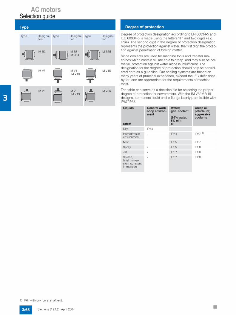
AC motorsSelection guide
Type
3/68 Siemens D 21.2 · April 2004
3
1) IP64 with dry run at shaft exit.
Type Designa-tion
Type Designa-tion
Type Designa-tion
IM B3 IM B5IM B14
IM B35
IM V5 IM V1 IM V18
IM V15
IM V6 IM V3 IM V19
IM V36
Degree of protection designation according to EN 60034-5 and IEC 60034-5 is made using the letters "IP" and two digits (e.g. IP64). The second digit in the degree of protection designation represents the protection against water, the first digit the protec-tion against penetration of foreign matter.
Since coolants are used for machine tools and transfer ma-chines which contain oil, are able to creep, and may also be cor-rosive, protection against water alone is insufficient. The designation for the degree of protection should only be consid-ered here as a guideline. Our sealing systems are based on many years of practical experience, exceed the IEC definitions by far, and are appropriate for the requirements of machine tools.
The table can serve as a decision aid for selecting the properdegree of protection for servomotors. With the IM V3/IM V19 designs, permanent liquid on the flange is only permissible with IP67/IP68.
Liquids
Effect
General work-shop environ-ment
Water;gen. coolant
(95% water,5% oil);oil
Creep oil;petroleum;aggressivecoolants
Dry IP64 -
Humid/moistenvironment
- IP64 IP67 1)
Mist IP65 IP67
Spray - IP65 IP68
Jet - IP67 IP68
Splash,brief immer-sion; constant immersion
- IP67 IP68
Degree of protection

Siemens D 21.2 · April 2004
4/2 Built-on optoelectronic rotary encoders
4/3 Incremental encoders4/3 Absolute encoders4/8 Mounting sets
4/9 SIMAG H2 hollow-shaftmeasuring system
Measuring systemsSIMODRIVE sensors

Measuring systemsSIMODRIVE sensors
Built-on optoelectronic rotary encoders
4/2 Siemens D 21.2 · April 2004
4
Overview
SIMODRIVE sensors are built-on optoelectronic encoders for re-cording paths, angles of rotation, or speeds of machines. They can be used in conjunction with numerical controllers, program-mable logic controllers, drives and position displays, e.g. in:7 SINAMICS drive systems7 SIMOTION Motion Control systems7 SINUMERIK CNC controls7 SIMATIC programmable logic controllers7 SIMODRIVE and SIMOVERT MASTERDRIVES
drive systems
Applications
A distinction is made between incremental and absolute mea-suring methods.• In the case of incremental encoders, the machine must travel
to a reference point after each power-off, as the position is not usually stored in the controller, and movements of the machine while the power is off are not recorded.
• Absolute encoders, on the other hand, record these move-ments while the power is off and return the actual position with power on. Travel to a reference point is not necessary.
Design
All encoders are available in synchronous-flange and flange joint versions. Synchronous-flange encoders can be fixed to the machine with 3 clamp straps or mounted with axial screws. The encoder is driven by means of a plug-in coupling or a spring disk coupling. Alternatively, pulleys can also be used.
The encoder supply voltage is 5 V DC or alternatively 10 V to 30 V DC. The 10 V to 30 V version supports longer cable lengths. The power supply for the measuring systems is pro-vided via the SMC sensor modules.
For rotary encoders with cables, the cable length including the connector is 1 m (3.3 ft).The following bending radii for the cables at the encoder must be complied with:• One-time bending: ≥ 20 mm (0.8 in)• Continuous bending: ≥ 75 mm (3 in)
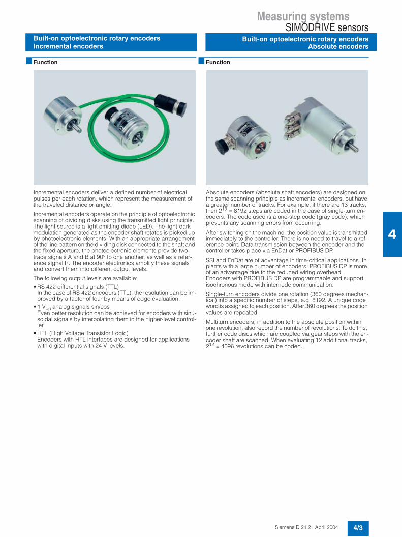
Measuring systems SIMODRIVE sensors
Built-on optoelectronic rotary encodersAbsolute encoders
4/3Siemens D 21.2 · April 2004
4
Built-on optoelectronic rotary encodersIncremental encoders
Function
Incremental encoders deliver a defined number of electrical pulses per each rotation, which represent the measurement of the traveled distance or angle.
Incremental encoders operate on the principle of optoelectronic scanning of dividing disks using the transmitted light principle. The light source is a light emitting diode (LED). The light-dark modulation generated as the encoder shaft rotates is picked up by photoelectronic elements. With an appropriate arrangement of the line pattern on the dividing disk connected to the shaft and the fixed aperture, the photoelectronic elements provide two trace signals A and B at 90° to one another, as well as a refer-ence signal R. The encoder electronics amplify these signals and convert them into different output levels.
The following output levels are available:• RS 422 differential signals (TTL)
In the case of RS 422 encoders (TTL), the resolution can be im-proved by a factor of four by means of edge evaluation.
• 1 Vpp analog signals sin/cos Even better resolution can be achieved for encoders with sinu-soidal signals by interpolating them in the higher-level control-ler.
• HTL (High Voltage Transistor Logic) Encoders with HTL interfaces are designed for applicationswith digital inputs with 24 V levels.
Function
Absolute encoders (absolute shaft encoders) are designed on the same scanning principle as incremental encoders, but havea greater number of tracks. For example, if there are 13 tracks,then 213 = 8192 steps are coded in the case of single-turn en-coders. The code used is a one-step code (gray code), which prevents any scanning errors from occurring.
After switching on the machine, the position value is transmitted immediately to the controller. There is no need to travel to a ref-erence point. Data transmission between the encoder and the controller takes place via EnDat or PROFIBUS DP.
SSI and EnDat are of advantage in time-critical applications. Inplants with a large number of encoders, PROFIBUS DP is more of an advantage due to the reduced wiring overhead.Encoders with PROFIBUS DP are programmable and support isochronous mode with internode communication.
Single-turn encoders divide one rotation (360 degrees mechan-ical) into a specific number of steps, e.g. 8192. A unique code word is assigned to each position. After 360 degrees the position values are repeated.
Multiturn encoders, in addition to the absolute position within one revolution, also record the number of revolutions. To do this, further code discs which are coupled via gear steps with the en-coder shaft are scanned. When evaluating 12 additional tracks, 212 = 4096 revolutions can be coded.

Measuring systemsSIMODRIVE sensors
Built-on optoelectronic rotary encodersIncremental encoders
4/4 Siemens D 21.2 · April 2004
4
Technical data
1) With recommended cable and input circuitry of the follow-up electronics, observe max. permissible cable length of module to be evaluated.
TTL (RS 422) incremental encoder
sin/cos 1 Vpp incrementalencoder
HTL incremental encoder
TTL (RS 422) double-track incremental encoder
Encoder operating voltage 5 V DC ±10% or 10 V to 30 V DC
5 V DC ±10% 10 V to 30 V DC 5 V DC ±5%
Limit frequency, typ. – ≥ 180 kHz (-3 dB) – –
– ≥ 450 kHz (-6 dB) – –
Sampling frequency (max.) 300 kHz – 300 kHz Track 1: 160 kHzTrack 2: 1 MHz
No-load current consumption (max.) 150 mA 150 mA per track
Signal level TTL (RS 422) sinusoidal 1 Vpp HTLVH ≥ 21 V atIH = 20 mA@ 24 VVL ≤ 2.8 V atIL = 20 mA@ 24 V
TTL (RS 422)
Outputs protected againstshort-circuit to 0 V
Yes
Switching time (10% to 90%)(with 1 m (3.3 ft) cable and recommended input circuit)
Rise/fall timet+/t- ≤ 50 ns
– Rise/fall timet+/t- ≤ 200 ns
Rise/fall timet+/t- ≤ 100 ns
Phase angle, signal A to Bmin. edge spacing at:
90 90 ±10°el. 90 90
• 1 MHz – – ≥ 0.125 µs (track 2)
• 300 kHz ≥ 0.45 µs – ≥ 0.45 µs –
• 160 kHz – – – ≥ 0.8 µs (track 1)
Cable length to electronic circuitry 1), max.
100 m (328 ft) 150 m (492 ft) 100 m (328 ft) 100 m (328 ft) (up to 500 kHz)50 m (164 ft) (up to 1 MHz)
LED failure monitoring High-resistance driver – High-resistance driver –
Resolution, max. 5000 S/R 2500 S/R 2500 S/R Track 1: 1024 S/RTrack 2: 9000 S/R
Accuracy(in angular seconds)
±18° mech. × 3600/resolution z Track 1: ±63Track 2: ±12
Permissible electr. speed (18 × 106 rpm) /revolution
(27 × 106 rpm) /revolution (at -6 dB)
(18 × 106 rpm) /revolution
Track 1: 9000 rpmTrack 2: 6500 rpm
Max. mech. speed 12000 rpm
Friction torque ≤ 0.01 Nm (0.08 lbƒ-in) (at 20°C (68°F))
Starting torque ≤ 0.01 Nm (0.08 lbƒ-in) (at 20°C (68°F))
Shaft load capability
• n > 6000 rpm Axial 10 N (2.2 lbƒ)/radial 20 N (4.5 lbƒ) at shaft extension –
• n ≤ 6000 rpm Axial 40 N (9 lbƒ)/radial 60 N (13.5 lbƒ) at shaft extension Axial 10 N (2.2 lbƒ)/radial 20 N (4.5 lbƒ) at shaft extension
Angular acceleration, max. > 105 rad/s2
Moment of inertia of rotor 1.45 × 10⁻⁶ kg m2 (12.83 x 10⁻⁶ lbƒ-in-s2) 20 × 10-6 kg m2 (177 x 10-6
lbƒ-in-s2)
Vibration (55 Hz to 2000 Hz) to DIN IEC 68-2-6
≤ 300 m/s2 (984 ft/s2) for encoder with cable≤ 150 m/s2 (492 ft/s2) for encoder with flange outlet
Shock (6 ms)to DIN IEC 68-2-27
≤ 2000 m/s2 (6563 ft/s2)
Operating temperature, max. +100 °C (212 °F) atVp = 5 V ±10%+70 °C (158 °F) atVp = 10 V to 30 V
+100 °C (212 °F) +85 °C (185 °F)+100 °C (212 °F) at Vp < 15 V
+70 °C (158 °F)
Operating temperature, min. Flange socket or fixed cable: -40 °C (-40 °F)Flexible cable: -10 °C (14 °F)
-10 °C (14 °F)
Degree of protection to DIN EN 60529 (IEC 60529)
IP67 without shaft inputIP64 with shaft input
EMC Tested in accordance with the electromagnetic compatibility directive 89/336/EEC and the regulationsof the EMC guidelines (applicable basic standards)
Weight, approx. 0.25 kg (0.55 lb) 0.7 kg (1.5 lb)
CE marking Yes

Measuring systems SIMODRIVE sensors
Built-on optoelectronic rotary encodersIncremental encoders
4/5Siemens D 21.2 · April 2004
4
Selection and ordering data
1) Universal integrated cable outlet for axial and radial outlet direction.S/R = Signals/Revolution
Designation Order No.
RS 422 interface (TTL) incremental encoder
Synchronous flange and5 V DC supply voltage
Connection:
• Axial flange outlet 6FX2001-2G7 7 7
• Radial flange outlet 6FX2001-2E7 7 7
• Cable 1 m (3.3 ft) with connector 1)
6FX2001-2C7 7 7
Synchronous flange and10 V to 30 V DC supply voltage
Connection:
• Axial flange outlet 6FX2001-2H7 7 7
• Radial flange outlet 6FX2001-2F7 7 7
• Cable 1 m (3.3 ft) with connector 1)
6FX2001-2D7 7 7
Supported flange joint and5 V DC supply voltage
Connection:
• Axial flange outlet 6FX2001-2R7 7 7
• Radial flange outlet 6FX2001-2P7 7 7
• Cable 1 m (3.3 ft) with connector 1)
6FX2001-2M7 7 7
Supported flange joint and10 V to 30 V DC supply voltage
Connection:
• Axial flange outlet 6FX2001-2S7 7 7
• Radial flange outlet 6FX2001-2Q7 7 7
• Cable 1 m (3.3 ft) with connector 1)
6FX2001-2N7 7 7
Resolution
500 S/R A 5 0
1000 S/R B 0 0
1024 S/R B 0 2
1250 S/R B 2 5
1500 S/R B 5 0
2000 S/R C 0 0
2048 S/R C 0 4
2500 S/R C 5 0
3600 S/R D 6 0
5000 S/R F 0 0
sin/cos 1 Vpp incremental encoder
Synchronous flange and5 V DC supply voltage
Connection:
• Axial flange outlet 6FX2001-3G7 7 7
• Radial flange outlet 6FX2001-3E7 7 7
• Cable 1 m (3.3 ft) with connector 1)
6FX2001-3C7 7 7
Resolution
1000 S/R B 0 0
1024 S/R B 0 2
2500 S/R C 5 0
Designation Order No.
HTL interface incremental encoder
Synchronous flange and 10 V to 30 V DC supply voltage
Connection:
• Axial flange outlet 6FX2001-4H 7 7 7
• Radial flange outlet 6FX2001-4F 7 7 7
• Cable 1 m (3.3 ft) withconnector 1)
6FX2001-4D 7 7 7
Supported flange joint and10 V to 30 V DC supply voltage
Connection:
• Axial flange outlet 6FX2001-4S 7 7 7
• Radial flange outlet 6FX2001-4Q 7 7 7
• Cable 1 m (3.3 ft) withconnector 1)
6FX2001-4N 7 7 7
Resolution
100 S/R A 1 0
500 S/R A 5 0
1000 S/R B 0 0
2500 S/R C 5 0
RS 422 interface (TTL) double-track incremental encoder
6FX2001-2UK00
Synchronous flange and 5 V DC supply voltage
Connection:
• Cable 1 m (3.3 ft) with axial connector2 types of resolution: 9000/1024 S/R
Replacement connectors with external threads for encoders(3x)
• 12-pole with 12 contact pinsfor incremental encoder with RS 422, sin/cos 1 Vpp HTLfor absolute encoder with SSI
6FX2003-1CF12
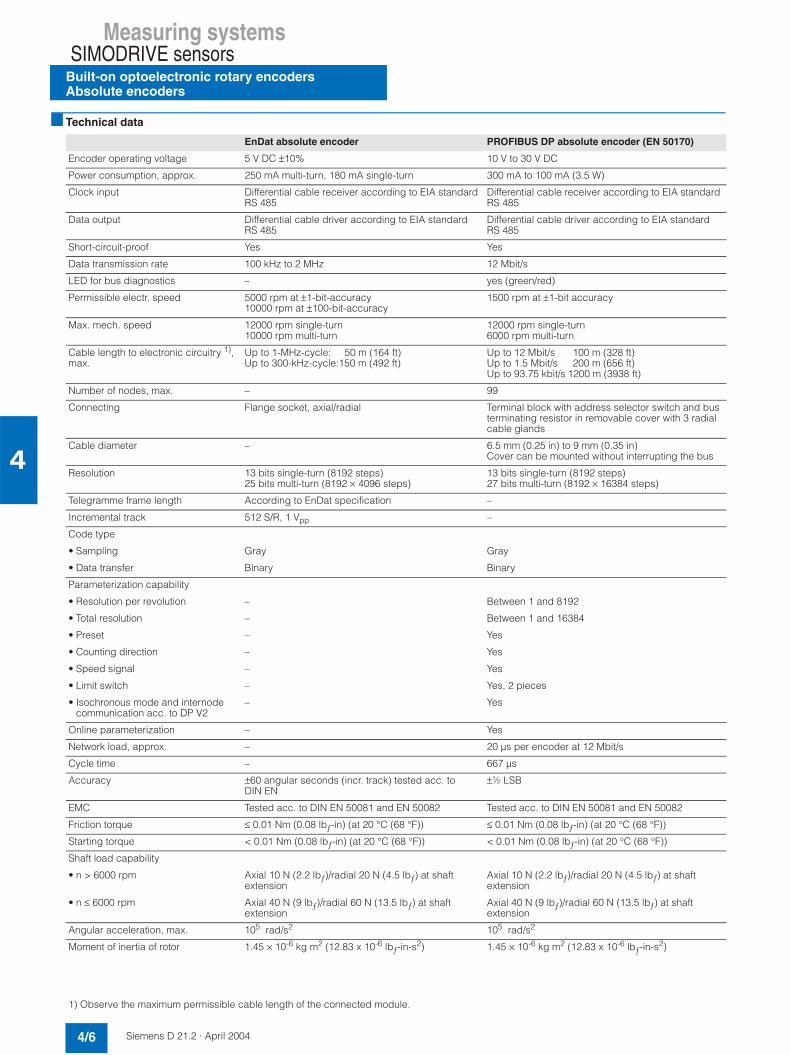
Measuring systemsSIMODRIVE sensors
Built-on optoelectronic rotary encodersAbsolute encoders
4/6 Siemens D 21.2 · April 2004
4
Technical data
EnDat absolute encoder PROFIBUS DP absolute encoder (EN 50170)
Encoder operating voltage 5 V DC ±10% 10 V to 30 V DC
Power consumption, approx. 250 mA multi-turn, 180 mA single-turn 300 mA to 100 mA (3.5 W)
Clock input Differential cable receiver according to EIA standard RS 485
Differential cable receiver according to EIA standard RS 485
Data output Differential cable driver according to EIA standardRS 485
Differential cable driver according to EIA standard RS 485
Short-circuit-proof Yes Yes
Data transmission rate 100 kHz to 2 MHz 12 Mbit/s
LED for bus diagnostics – yes (green/red)
Permissible electr. speed 5000 rpm at ±1-bit-accuracy10000 rpm at ±100-bit-accuracy
1500 rpm at ±1-bit accuracy
Max. mech. speed 12000 rpm single-turn10000 rpm multi-turn
12000 rpm single-turn6000 rpm multi-turn
Cable length to electronic circuitry 1),max.
Up to 1-MHz-cycle: 50 m (164 ft)Up to 300-kHz-cycle:150 m (492 ft)
Up to 12 Mbit/s 100 m (328 ft)Up to 1.5 Mbit/s 200 m (656 ft)Up to 93.75 kbit/s 1200 m (3938 ft)
Number of nodes, max. – 99
Connecting Flange socket, axial/radial Terminal block with address selector switch and bus terminating resistor in removable cover with 3 radial cable glands
Cable diameter – 6.5 mm (0.25 in) to 9 mm (0.35 in)Cover can be mounted without interrupting the bus
Resolution 13 bits single-turn (8192 steps)25 bits multi-turn (8192 × 4096 steps)
13 bits single-turn (8192 steps)27 bits multi-turn (8192 × 16384 steps)
Telegramme frame length According to EnDat specification –
Incremental track 512 S/R, 1 Vpp –
Code type
• Sampling Gray Gray
• Data transfer Binary Binary
Parameterization capability
• Resolution per revolution – Between 1 and 8192
• Total resolution – Between 1 and 16384
• Preset – Yes
• Counting direction – Yes
• Speed signal – Yes
• Limit switch – Yes, 2 pieces
• Isochronous mode and internode communication acc. to DP V2
– Yes
Online parameterization – Yes
Network load, approx. – 20 µs per encoder at 12 Mbit/s
Cycle time – 667 µs
Accuracy ±60 angular seconds (incr. track) tested acc. to DIN EN
±½ LSB
EMC Tested acc. to DIN EN 50081 and EN 50082 Tested acc. to DIN EN 50081 and EN 50082
Friction torque ≤ 0.01 Nm (0.08 lbƒ-in) (at 20 °C (68 °F)) ≤ 0.01 Nm (0.08 lbƒ-in) (at 20 °C (68 °F))
Starting torque < 0.01 Nm (0.08 lbƒ-in) (at 20 °C (68 °F)) < 0.01 Nm (0.08 lbƒ-in) (at 20 °C (68 °F))
Shaft load capability
• n > 6000 rpm Axial 10 N (2.2 lbƒ)/radial 20 N (4.5 lbƒ) at shaft extension
Axial 10 N (2.2 lbƒ)/radial 20 N (4.5 lbƒ) at shaftextension
• n ≤ 6000 rpm Axial 40 N (9 lbƒ)/radial 60 N (13.5 lbƒ) at shaftextension
Axial 40 N (9 lbƒ)/radial 60 N (13.5 lbƒ) at shaft extension
Angular acceleration, max. 105 rad/s2 105 rad/s2
Moment of inertia of rotor 1.45 × 10⁻⁶ kg m2 (12.83 x 10⁻⁶ lbƒ-in-s2) 1.45 × 10⁻⁶ kg m2 (12.83 x 10⁻⁶ lbƒ-in-s2)
1) Observe the maximum permissible cable length of the connected module.

Measuring systems SIMODRIVE sensors
Built-on optoelectronic rotary encodersAbsolute encoders
4/7Siemens D 21.2 · April 2004
4
Technical data (continued)
Selection and ordering data
EnDat absolute encoder PROFIBUS DP absolute encoder (EN 50170)
Vibration (55 Hz to 2000 Hz) toDIN IEC 668-2-6
≤ 100 m/s2 (328 ft/s2) ≤ 100 m/s2 (328 ft/s2)
Shock (6 ms) to DIN IEC 668-2-27 ≤ 1000 m/s2 (3281 ft/s2) ≤ 1000 m/s2 (3281 ft/s2)
Operating temperature, max. +100 °C (212 °F) +70 °C (158 °F)
Operating temperature, min. -40 °C (-40 °F) -40 °C (-40 °F)
Degree of protection to DIN EN 60529 (IEC 60529)
IP67 without shaft inputIP64 with shaft input
IP67 without shaft inputIP64 with shaft input
Weight, approx.Single-turn/Multi-turn 0.35 kg (0.8 lb)/0.35 kg (0.8 lb) 0.5 kg (1.1 lb)/0.7 kg (1.5 lb)
CE marking Yes Yes
PROFIBUS certificate – Yes
Supported profiles – Class 1, Class 2
Designation Order No.
EnDat absolute encoder
Synchronous flange and 5 V DC supply voltage
Connection:
• EnDat with axial flange outlet 6FX2001-5HE7 7
• EnDat with radial flange outlet 6FX2001-5FE7 7
Supported flange joint and 5 V DC supply voltage
Connection:
• EnDat with axial flange outlet 6FX2001-5SE7 7
• EnDat with radial flange outlet 6FX2001-5QE7 7
Resolution
• Single-turn8192 steps/revolution(13 bits)
1 3
• Multi-turn 8192 steps/revolution,4096 revolutions(25 bits)
2 5
• Radial connection 6FX2001-5QP7 7
Resolution
• Single-turn8192 steps/revolution(13 bits)
1 2
Designation Order No.
PROFIBUS DP absolute encoder
Synchronous flange and10 V to 30 V DC supply voltage
• Radial connection 6FX2001-5FP7 7
Supported flange joint and 10 V to 30 V DC supply voltage
• Multi-turn 8192 steps/revolution,16384 revolutions(27 bits)
2 4
User Manualfor start-up and parameterization of PROFIBUS encodersLanguages: German/English
6SN1197-0AB10-0YP3
Replacement connectors with external threads for encoders(3x)
• 12-pole with 12 contact pinsfor incremental encoder with RS 422, sin/cos 1 Vpp HTLfor absolute encoder with SSI
6FX2003-1CF12
• 17-pole with 17 contact pinsfor absolute encoder with EnDat
6FX2003-1CF17

Measuring systemsSIMODRIVE sensors
Built-on optoelectronic rotary encodersMounting accessories
4/8 Siemens D 21.2 · April 2004
4
Overview
Clamp straps/couplings
Clamp straps and couplings are available as mounting accesso-ries for the rotary encoders. The clamp straps are used to fix the encoders with a synchronous flange.
Mating connector
A mating connector is available for the encoder with flangesocket or with cable and encoder connector for cable diameters 5.5 mm (0.2 in) to 12 mm (0.5 in). Connectors with 12 contact pins are suitable for all incremental encoders. Connectors with17 contacts are suitable for encoders with EnDat.
Technical data
Selection and ordering data
Spring disk coupling
Plug-incoupling
Transmission torque, max. 0.8 Nm (7 lbƒ-in) 0.7 Nm (6.2 lbƒ-in)
Shaft diameter 6 mm (0.2 in) on both sides or d1 = 6 mm (0.2 in), d2 = 5 mm (0.2 in)
6 mm (0.2 in) on both sides or 10 mm (0.4 in) on both sides
Center offset of shafts max. 0.4 mm (0.01 in) 0.5 mm (0.02 in)
Axial offset ±0.4 mm (0.01 in) ±0.5 mm (0.02 in)
Angular displacement ofshafts, max.
3° 1°
Torsional rigidity 150 Nm/rad (1327.5 lbƒ-in/rad)
31 Nm/rad (274.3 lbƒ-in/rad)
Lateral spring stiffness 6 N/mm (1.34 lbƒ-in)
10 N/mm (2.25 lbƒ-in)
Moment of inertia 19 gcm2
(168 x 10-7 lbƒ-in-s2)20 gcm2
(177 x 10-7 lbƒ-in-s2)
Max. speed 12000 rpm 12000 rpm
Operating temperature• Maximum +150 °C (302 °F) +80 °C (176 °F)• Minimum -40 °C (-40 °F) -40 °C (-40 °F)
Weight, approx. 16 g (0.03 lb) 20 g (0.04 lb)
Designation Order No.
Clamp strapfor double-track encoder and encoder with synchro flange (3 units are required)
6FX2001-7KP01
Spring disk couplingShaft diameter:
• 6 mm (0.2 in)/6 mm (0.2 in) 6FX2001-7KF10
• 6 mm (0.2 in)/5 mm (0.2 in) 6FX2001-7KF06
Plug-in couplingShaft diameter:
• 6 mm (0.2 in)/6 mm (0.2 in) 6FX2001-7KS06
• 10 mm (0.4 in)/10 mm (0.4 in) 6FX2001-7KS10
Mating connector for flangeoutlet or encoder connectorCrimp version, socket contacts for cable diameters 5.5 mm (0.2 in) to 12 mm (0.5 in) (3 units)
• 12-pin, 12 socket contactsfor incremental encoder with TTL, sin/cos 1 Vpp, HTL
6FX2003-0CE12
• 17-pin, 17 socket contactsfor absolute encoder with EnDat
6FX2003-0CE17

Measuring systems SIMODRIVE sensors
SIMAG H2 hollow-shaft measuring system
4/9Siemens D 21.2 · April 2004
4
Applications
SIMAG H2 is an incremental system for measuring angles of ro-tation and rotational speeds. Applications include hollow-shaft applications with direct drives, e.g. 1PH2, as well as applica-tions as an autonomous spindle encoder. SIMAG H2 is intended to replace the SIZAG 2 hollow-shaft measuring system in new applications.
The electrical signals and the flange outlet are compatible with existing motor measuring systems. SIMAG H2 can be operated digitally on SINAMICS S120 converter systems with all available controls as a motor measuring system or as direct measuring system.
Design
The SIMAG H2 measuring system consists of three components:7 Measuring wheel7 Scanning head with connecting lead7 Connection kit
The magnetic division on the measuring wheel is used as unit of measurement. Different internal diameters are available for each outer diameter, whereby the internal diameter can be re-worked. The measuring wheel is attached with the shaft nut; alternatives are screw fitting to a shaft shoulder (not possible with all mea-surement variants) or shrink fitting.
The non-contact scanning head scans the incremental and ref-erence tracks at the measuring wheel and amplifies the signals.
It is connected via a lead attached to the scanning head. The end of the lead is preassembled with contacts and an insulation insert. For assembly, the insulation insert can be fixed into a straight or angular flange outlet. For confined spaces, the en-coder can also be supplied with open core ends.
Technical data
1) The internal diameters can be re-worked (hollowed up to max. 65 mm(2.6 in)); see Planning/Installation Guide.
Selection and ordering data
SIMAG H2 hollow-shaft measuring system
Output signals 2 voltage signals 1 Vppin quadrative; 1 reference signal per encoder revolution
Operating voltage 5 V DC ±5%
Current consumption, typ. 30 mA
Resolution 256 S/R
Indexing accuracy of measuring wheel
±72 angular seconds atresolution = 256 S/R
Limiting speed ≤ 25000 rpm at 256 S/R
Rated distance between measur-ing wheel and scanning head
200 µm
Operating temperature range -20 °C to +120 °C (-4 °F to +248 °F)
Shock resistance (11 ms) 1000 m/s2 (3281 ft/s2)
Vibration (50 Hz to 2000 Hz) 200 m/s2 (656 ft/s2)
Degree of protection to DIN EN 60529 (IEC 60529)
IP67 when installed
Bending radius of the cable mod-ule lines
One-time bending: ≥ 25 mm (1 in)Multiple bending: ≥ 60 mm (2.4 in)
Max. length of cable to converter 50 m (164 ft)
Dimensions (W x H x D), approx. Scanning head (mounted)
37 mm x 18 (+4) mm x 16 mm(1.5 in x 0.7 (+0.1) in x 0.6 in)
Measuring wheel
Internal diameter1) 45H6 mm (1.8H6 in) 60H6 mm (2.4H6 in)
External diameter Da 81.14 mm (3.2 in)
Thickness 15 mm (0.6 in)
Pulse number 256
Moment of inertia, approx. 4 x 10⁻⁴ kg m2
(35.4x10⁻⁴ lbƒ-in-s2)3 x 10⁻⁴ kg m2
(26.5x10⁻⁴ lbƒ-in-s2)
Weight, approx. 0.4 kg (0.9 lb) 0.25 kg (0.5 lb)
Designation Order No.
Scanning head, incremental
1 mm pole pitch, 1 Vpp
• with plug insertwith 0.2 m (0.7 ft) cable
6FX2001-6AA12-1CA0
• with plug insertwith 0.5 m (1.6 ft) cable
6FX2001-6AA12-1FA0
• with plug insertwith 2 m (6.6 ft) cable
6FX2001-6AA12-3AA0
• open core endswith 1 m (3.3 ft) cable
6FX2001-6AA12-2AA5
Measuring wheel, Da 81.14 mm (3.2 in)
• Internal diameter 45H6 mm (1.8H6 in) 6FX2001-6RB12-4EF0
• Internal diameter 60H6 mm (2.4H6 in) 6FX2001-6RB12-4GA0
Connection kit for insulation insert
• Straight flange outlet 6FX2001-6FA12-0GA0
• Angular flange outlet 6FX2001-6FA12-0WA0
Extraction tool for insulation insertof straight or angular flange outlet
6FX2001-6FK12-0AA0
Planning/Installation Guide
• German 6SN1197-0AB30-0AP2
• English 6SN1197-0AB30-0BP2
Measuring systemsSIMODRIVE sensors
SIMAG H2 hollow-shaft measuring system
4/10 Siemens D 21.2 · April 2004
4
Siemens D 21.2 · April 2004
5/2 General information5/2 Technical data5/4 Function
5/5 Power cables5/7 Extensions
5/8 Signal cables5/11 Extensions
5/12 Length code
MOTION-CONNECTconnection system
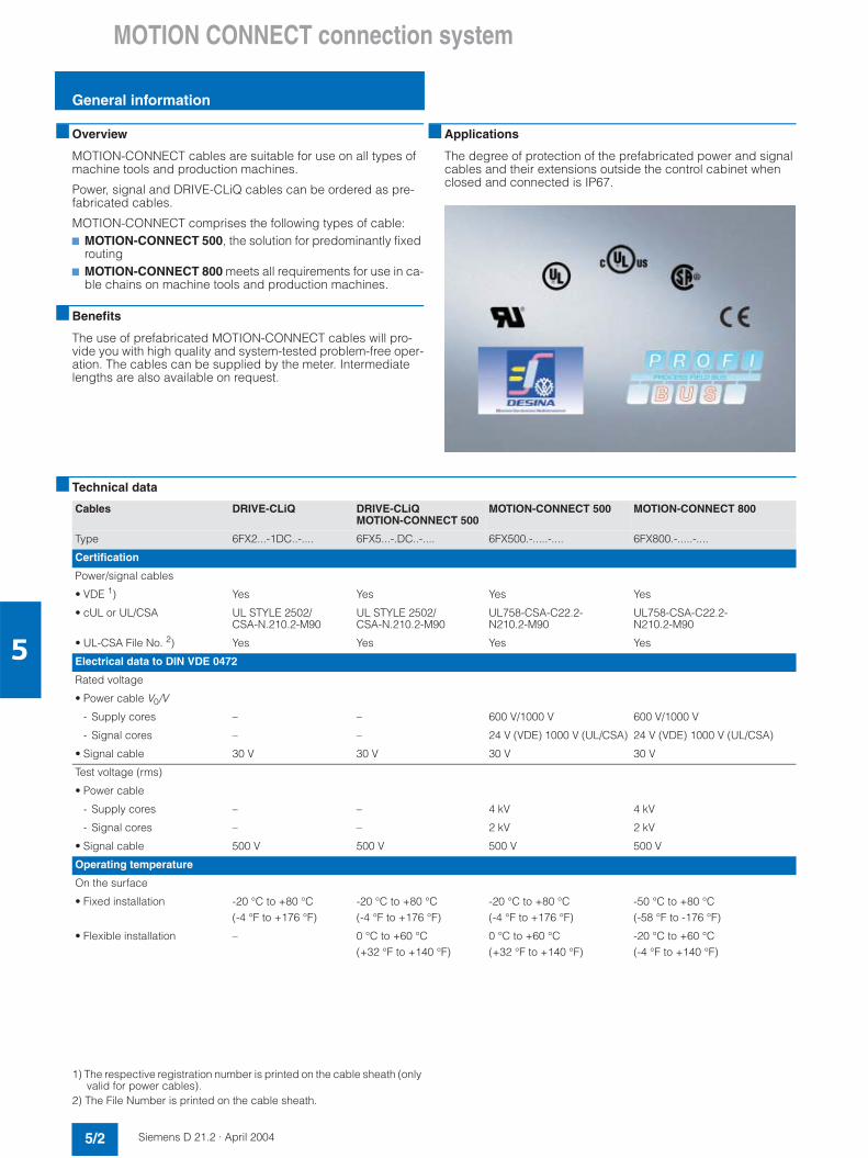
MOTION CONNECT connection system
General information
5/2 Siemens D 21.2 · April 2004
5
Overview
MOTION-CONNECT cables are suitable for use on all types of machine tools and production machines.
Power, signal and DRIVE-CLiQ cables can be ordered as pre-fabricated cables.
MOTION-CONNECT comprises the following types of cable:7 MOTION-CONNECT 500, the solution for predominantly fixed
routing7 MOTION-CONNECT 800 meets all requirements for use in ca-
ble chains on machine tools and production machines.
Benefits
The use of prefabricated MOTION-CONNECT cables will pro-vide you with high quality and system-tested problem-free oper-ation. The cables can be supplied by the meter. Intermediatelengths are also available on request.
Applications
The degree of protection of the prefabricated power and signal cables and their extensions outside the control cabinet when closed and connected is IP67.
Technical data
1) The respective registration number is printed on the cable sheath (only valid for power cables).
2) The File Number is printed on the cable sheath.
Cables DRIVE-CLiQ DRIVE-CLiQMOTION-CONNECT 500
MOTION-CONNECT 500 MOTION-CONNECT 800
Type 6FX2...-1DC..-.... 6FX5...-.DC..-.... 6FX500.-.....-.... 6FX800.-.....-....
Certification
Power/signal cables
• VDE 1) Yes Yes Yes Yes
• cUL or UL/CSA UL STYLE 2502/CSA-N.210.2-M90
UL STYLE 2502/CSA-N.210.2-M90
UL758-CSA-C22.2-N210.2-M90
UL758-CSA-C22.2-N210.2-M90
• UL-CSA File No. 2) Yes Yes Yes Yes
Electrical data to DIN VDE 0472
Rated voltage
• Power cable V0/V
- Supply cores – – 600 V/1000 V 600 V/1000 V
- Signal cores – – 24 V (VDE) 1000 V (UL/CSA) 24 V (VDE) 1000 V (UL/CSA)
• Signal cable 30 V 30 V 30 V 30 V
Test voltage (rms)
• Power cable
- Supply cores – – 4 kV 4 kV
- Signal cores – – 2 kV 2 kV
• Signal cable 500 V 500 V 500 V 500 V
Operating temperature
On the surface
• Fixed installation -20 °C to +80 °C(-4 °F to +176 °F)
-20 °C to +80 °C(-4 °F to +176 °F)
-20 °C to +80 °C(-4 °F to +176 °F)
-50 °C to +80 °C(-58 °F to -176 °F)
• Flexible installation – 0 °C to +60 °C(+32 °F to +140 °F)
0 °C to +60 °C(+32 °F to +140 °F)
-20 °C to +60 °C(-4 °F to +140 °F)
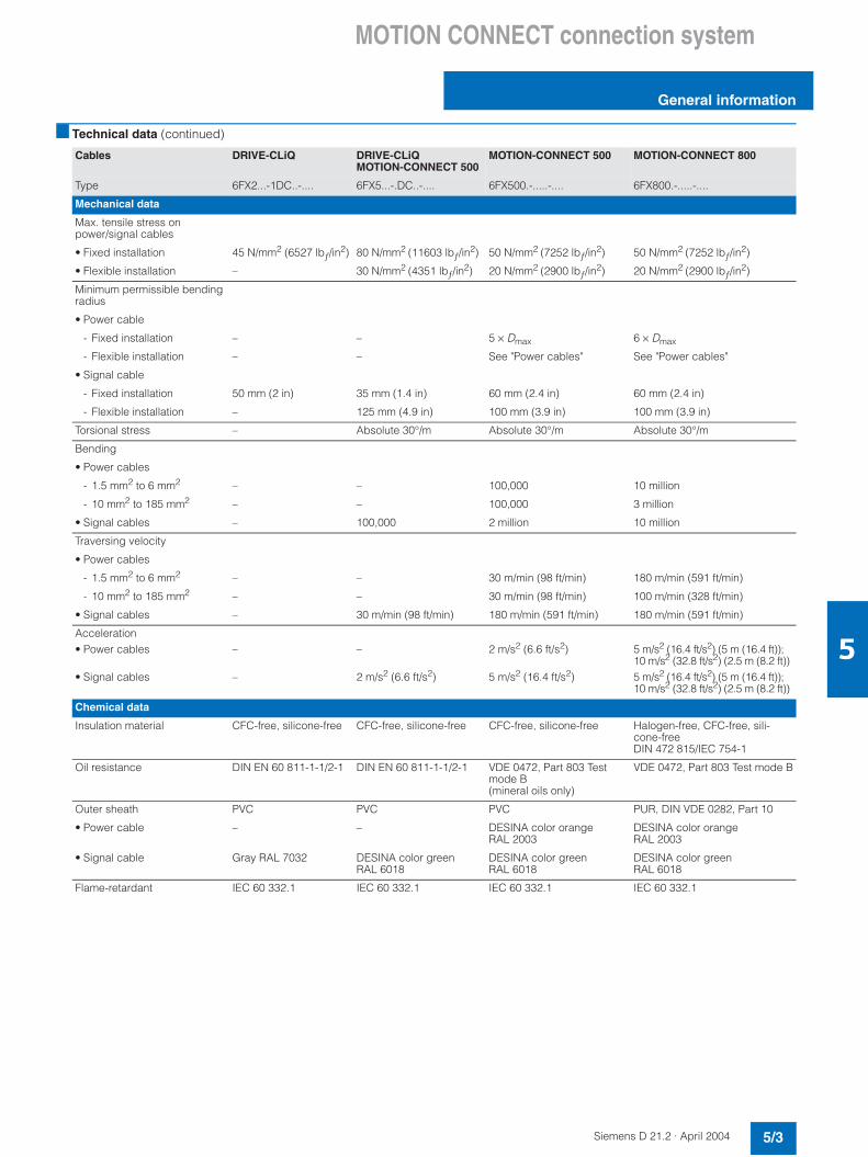
MOTION CONNECT connection system
General information
5/3Siemens D 21.2 · April 2004
5
Technical data (continued)
Cables DRIVE-CLiQ DRIVE-CLiQMOTION-CONNECT 500
MOTION-CONNECT 500 MOTION-CONNECT 800
Type 6FX2...-1DC..-.... 6FX5...-.DC..-.... 6FX500.-.....-.... 6FX800.-.....-....
Mechanical data
Max. tensile stress on power/signal cables
• Fixed installation 45 N/mm2 (6527 lbƒ/in2) 80 N/mm2 (11603 lbƒ/in2) 50 N/mm2 (7252 lbƒ/in2) 50 N/mm2 (7252 lbƒ/in2)
• Flexible installation – 30 N/mm2 (4351 lbƒ/in2) 20 N/mm2 (2900 lbƒ/in2) 20 N/mm2 (2900 lbƒ/in2)
Minimum permissible bendingradius
• Power cable
- Fixed installation – – 5 × Dmax 6 × Dmax
- Flexible installation – – See "Power cables" See "Power cables"
• Signal cable
- Fixed installation 50 mm (2 in) 35 mm (1.4 in) 60 mm (2.4 in) 60 mm (2.4 in)
- Flexible installation – 125 mm (4.9 in) 100 mm (3.9 in) 100 mm (3.9 in)
Torsional stress – Absolute 30°/m Absolute 30°/m Absolute 30°/m
Bending
• Power cables
- 1.5 mm2 to 6 mm2 – – 100,000 10 million
- 10 mm2 to 185 mm2 – – 100,000 3 million
• Signal cables – 100,000 2 million 10 million
Traversing velocity
• Power cables
- 1.5 mm2 to 6 mm2 – – 30 m/min (98 ft/min) 180 m/min (591 ft/min)
- 10 mm2 to 185 mm2 – – 30 m/min (98 ft/min) 100 m/min (328 ft/min)
• Signal cables – 30 m/min (98 ft/min) 180 m/min (591 ft/min) 180 m/min (591 ft/min)
Acceleration• Power cables
• Signal cables
–
–
–
2 m/s2 (6.6 ft/s2)
2 m/s2 (6.6 ft/s2)
5 m/s2 (16.4 ft/s2)
5 m/s2 (16.4 ft/s2) (5 m (16.4 ft)); 10 m/s2 (32.8 ft/s2) (2.5 m (8.2 ft))5 m/s2 (16.4 ft/s2) (5 m (16.4 ft)); 10 m/s2 (32.8 ft/s2) (2.5 m (8.2 ft))
Chemical data
Insulation material CFC-free, silicone-free CFC-free, silicone-free CFC-free, silicone-free Halogen-free, CFC-free, sili-cone-freeDIN 472 815/IEC 754-1
Oil resistance DIN EN 60 811-1-1/2-1 DIN EN 60 811-1-1/2-1 VDE 0472, Part 803 Testmode B(mineral oils only)
VDE 0472, Part 803 Test mode B
Outer sheath PVC PVC PVC PUR, DIN VDE 0282, Part 10
• Power cable – – DESINA color orange RAL 2003
DESINA color orangeRAL 2003
• Signal cable Gray RAL 7032 DESINA color green RAL 6018
DESINA color greenRAL 6018
DESINA color green RAL 6018
Flame-retardant IEC 60 332.1 IEC 60 332.1 IEC 60 332.1 IEC 60 332.1

MOTION CONNECT connection system
General information
5/4 Siemens D 21.2 · April 2004
5
Function
The cables must be removed from the drum without twisting, i.e. the cables must be unwound and must never be lifted over the drum flange while still wound in loops.
To maximize the service life of the cable chain and cables, ca-bles in the chain made from different materials must be installed in the cable chain using spacers. The spacers must be installed uniformly to ensure that the position of the cables does notchange during operation. The cables should be distributed as symmetrically as possible on the basis of their weight and di-mensions. Cables with very different outer diameters should be separated by spacers.
When installing prefabricated cables in the cable chain, do notpull on the connector, as this may damage the strain relief or ca-ble clamping.
The cables must not be fixed in the chain and must have room to move.
The cables must be able to move unrestricted in particular in the radii of curvature of the chain. The prescribed minimum bending radii must not be undershot.
The cable fixings must be attached at both ends at an appropri-ate distance away from the end points of the moving parts in a"dead" zone.
Siemens cables are tested for use in a cable chain. During test-ing, a strain-relief assembly is attached to one end of the cableat the moving ends of the cable chain. Strain relief is applied to a wide area of the peripheral surface without crushing the cable assembly.
When installing cables, you must always observe the information in the Installation Guide provided by the cable chain manufac-turer as appropriate for the way in which the system has been constructed.
Notes:
If, for example, prefabricated cables are installed in a cable chain in such a way that the connector would inhibit assembly, prefabricated cables without assembled connectors can also be supplied (signal and power cables). On these cables, the con-tacts are crimped and the connector housing is supplied sepa-rately packed. Once the cables have been installed, the cus-tomer assembles the connector housing.
When installing cables, you must always observe the information provided by the cable chain manufacturer.
In the event of vibrational loads and if horizontal or vertical cable entries are used, we always recommend the use of an additional cable fixing, if part of the cable hangs loose or is not guided inbetween the strain relief on the cable chain and the connection on the motor. To prevent machine vibrations being transmitted to the connectors, the cable fixing on the moving part should be connected in the same place as the motor.
4:: $
4::$
4::$
Our cables have been approved for a maximum horizontaltraverse path of 5 m (16.4 ft).
4
::
$
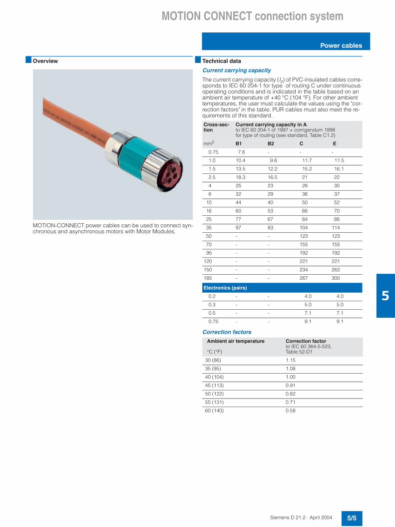
MOTION CONNECT connection system
Power cables
5/5Siemens D 21.2 · April 2004
5
Overview
MOTION-CONNECT power cables can be used to connect syn-chronous and asynchronous motors with Motor Modules.
Technical data
Current carrying capacity
The current carrying capacity (Iz) of PVC-insulated cables corre-sponds to IEC 60 204-1 for type of routing C under continuous operating conditions and is indicated in the table based on anambient air temperature of +40 °C (104 °F). For other ambienttemperatures, the user must calculate the values using the "cor-rection factors" in the table. PUR cables must also meet the re-quirements of this standard.
Correction factors
Cross-sec-tion
Current carrying capacity in Ato IEC 60 204-1 of 1997 + corrigendum 1998for type of routing (see standard, Table C1.2)
mm2 B1 B2 C E
0.75 7.6 - - -
1.0 10.4 9.6 11.7 11.5
1.5 13.5 12.2 15.2 16.1
2.5 18.3 16.5 21 22
4 25 23 28 30
6 32 29 36 37
10 44 40 50 52
16 60 53 66 70
25 77 67 84 88
35 97 83 104 114
50 - - 123 123
70 - - 155 155
95 - - 192 192
120 - - 221 221
150 - - 234 262
185 - - 267 300
Electronics (pairs)
0.2 - - 4.0 4.0
0.3 - - 5.0 5.0
0.5 - - 7.1 7.1
0.75 - - 9.1 9.1
Ambient air temperature
°C (°F)
Correction factorto IEC 60 364-5-523, Table 52-D1
30 (86) 1.15
35 (95) 1.08
40 (104) 1.00
45 (113) 0.91
50 (122) 0.82
55 (131) 0.71
60 (140) 0.58

MOTION CONNECT connection system
Power cables
5/6 Siemens D 21.2 · April 2004
5
Selection and ordering data
MOTION-CONNECT power cables without brake cores
MOTION-CONNECT power cables with brake cores
Connectionmethod,motormoduleside
No. of cores x cross-sec-tion
Connectorsize,motor side
Prefabricated cable for 1FT/1FK motors
Dmax. Weight (excluding connector)
Smallest permissiblebending radius 1)
6FX5 6FX8 6FX5 6FX8 6FX5 6FX8mm2 Order No. mm (in) mm (in) kg/m (lb/ft) kg/m (lb/ft) mm (in) mm (in)
Connector 4×1.5 1 6FX7002-5CS01-7 7 70 8.4 (0.3) 10.4 (0.4) 0.18 (0.4) 0.16 (0.4) 155 (6.1) 100 (4)
1.5 6FX7002-5CS21-7 7 70
open coreends 2)
6FX5002-5CS02- 7 7 70
Connector 4×2.5 1 6FX7002-5CS11-7 7 70 10 (0.4) 12.1 (0.5) 0.24 (0.5) 0.24 (0.5) 180 (7.1) 120 (4.8)
1.5 6FX7002-5CS31-7 7 70
open coreends 2)
6FX5002-5CS12- 7 7 70
Connector 4×4 1.5 6FX7002-5CS41-7 7 70 11.4 (0.4) 13.2 (0.5) 0.32 (0.7) 0.31 (0.7) 210 (8.3) 130 (5.1)
open coreends 2)
6FX5002-5CS42- 7 7 70
Connector 4×6 1.5 6FX7002-5CS51-7 7 70 13.6 (0.5) 16 (0.6) 0.46 (1) 0.43 (1) 245 (9.6) 170 (6.7)
open coreends 2)
6FX5002-5CS52- 7 7 70
Connector 4×10 1.5 6FX7002-5CS61-7 7 70 20 (0.8) 19.4 (0.8) 0.73 (1.6) 0.63 (1.4) 360 (14.1) 210 (8.3)
3 6FX7002-5CS13-7 7 70
open coreends 2)
6FX5002-5CS62- 7 7 70
Ring termi-nal ends
4×6 1.5 6FX7002-5CS54-7 7 70 15.6 (0.6) 16 (0.6) 0.46 (1) 0.43 (1) 285 (11.2) 170 (6.7)
4×10 1.5 6FX7002-5CS64-7 7 70 20 (0.8) 19.4 (0.8) 0.73 (1.6) 0.63 (1.4) 360 (14.1) 210 (8.3)
4×16 3 6FX7002-5CS23-7 7 70 24.2 (1) 23.6 (1) 1.1 (2.4) 0.95 (2.1) 440 (17.3) 260 (10.2)
Type of power cable
• MOTION-CONNECT 500• MOTION-CONNECT 800
Length code
58
. ..
Connectionmethod,motormoduleside
No. of cores x cross-sec-tion
Connectorsize,motor side
Prefabricated cable for 1FT/1FK motors
Dmax. Weight (excluding connector)
Smallest permissiblebending radius 1)
mm2 6FX5 6FX8 6FX5 6FX8 6FX5 6FX8Order No. mm (in) mm (in) kg/m (lb/ft) kg/m (lb/ft) mm (in) mm (in)
Connector 4×1.5+2×1.5 1 6FX7002-5DS01-7 7 70 10.8 (0.4) 12.9 (0.5) 0.22 (0.5) 0.25 (0.6) 195 (7.7) 125 (5)
1.5 6FX7002-5DS21-7 7 70
Connector 4×2.5+2×1.5 1 6FX7002-5DS11-7 7 70 12.4 (0.5) 14.2 (0.5) 0.28 (0.6) 0.31 (0.7) 225 (8.9) 140 (5.5)
1.5 6FX7002-5DS31-7 7 70
Connector 4×4+2×1.5 1.5 6FX7002-5DS41-7 7 70 14 (0.6) 15.3 (0.6) 0.36 (0.8) 0.4 (0.9) 255 (10) 150 (5.9)
Connector 4×6+2×1.5 1.5 6FX7002-5DS51-7 7 70 16.1 (0.6) 17.8 (0.7) 0.54 (1.2) 0.53 (1.2) 290 (11.4) 195 (7.7)
Connector 4×10+2×1.5 1.5 6FX7002-5DS61-7 7 70 21.7 (0.9) 20.8 (0.9) 0.75 (1.7) 0.74 (1.6) 395 (15.6) 230 (9.1)
3 6FX7002-5DS13-7 7 70
Ring termi-nal ends
4×6+2×1.5 1.5 6FX7002-5DS54-7 7 70 16.1 (0.6) 17.8 (0.7) 0.54 (1.2) 0.53 (1.2) 290 (11.4) 195 (7.7)
4×10+2×1.5 1.5 6FX7002-5DS64-7 7 70 21.7 (0.9) 20.8 (0.9) 0.75 (1.7) 0.74 (1.6) 395 (15.6) 230 (9.1)
4×16+2×1.5 3 6FX5002-5DS23- 7 7 70 25 (1) 24.7 (1) 1.1 (2.4) 1.1 (2.4) 450 (17.7) 275 (10.8)
4×25+2×1.5 3 6FX5002-5DS33- 7 7 70 29.4 (1.2) 27.9 (1.1) 1.56 (3.4) 1.46 (3.2) 530 (21) 325 (12.8)
4×35+2×1.5 3 6FX5002-5DS43- 7 7 70 32.6 (1.3) 32 (1.3) 2.01 (4.4) 2.1 (4.6) 590 (23.2) 380 (15)
4×50+2×1.5 3 6FX5002-5DS53- 7 7 70 38 (1.5) 35.8 (1.4) 3.30 (7.3) 2.75 (6.1) 685 (27) 420 (16.5)
Type of power cable
• MOTION-CONNECT 500• MOTION-CONNECT 800
Length code
58
. .. 1) Valid for installation in cable chain.

MOTION CONNECT connection system
Power cablesExtensions
5/7Siemens D 21.2 · April 2004
5
Selection and ordering data
Power cable extensions
The power cable extension combinations shown are examples.
Overview
Flange
Flanges are used to route or fix connectors in control cabinets. With the exception of right-angle plugs, a flange can be mounted on site on connectors using union nuts or connectors with external threads.
HF (high-frequency) clamp
To guarantee correct grounding on the cable duct or cabinet wall, a ground clamp can be ordered as an accessory together with the flanges for discharging high-frequency interference over a large area.
Selection and ordering data
Dimension drawings
Dimensions in mm (inches)
No. of cores x cross-section
Basic cable for 1FT/1FK motors
Connector size Extension Connector size
mm2 Type Order No.
4×1.5 6FX . 002-5 . S01- . . . 0 1 6FX7002-57A05-7 7 7 0 1
4×2.5 6FX . 002-5 . S11- . . . 0 1 6FX7002-57A15-7 7 7 0 1
4×1.5 6FX . 002-5 . S21- . . . 0 1.5 6FX7002-57A28-7 7 7 0 1.5
4×2.5 6FX . 002-5 . S31- . . . 0 1.5 6FX7002-57A38-7 7 7 0 1.5
4×4 6FX . 002-5 . S41- . . . 0 1.5 6FX7002-57A48-7 7 7 0 1.5
4×6 6FX . 002-5 . S51- . . . 0 1.5 6FX7002-57A58-7 7 7 0 1.5
4×10 6FX . 002-5 . S61- . . . 0 1.5 6FX7002-57A68-7 7 7 0 1.5
4×10 6FX . 002-5 . S13- . . . 0 3 6FX7002-57X18-7 7 7 0 3
4×16 6FX . 002-5 . S23- . . . 0 3 6FX7002-57X28-7 7 7 0 3
4×25 6FX . 002-5DS33- . . . 0 3 6FX7002-5DX38-7 7 7 0 3
Type of power cable
• MOTION-CONNECT 500• MOTION-CONNECT 800
• Without brake cores• With brake cores
Length code
58
CD
. ..
Designation Order No.
Flange for
• Connector size 1 6FX2003-7BX00
• Connector size 1.5 6FX2003-7CX00
• Connector size 3 6FX2003-7AX00
HF clamp for
• Power connector, Size 1 6FX2003-7FX00
• Power connector, Size 1.5 6FX2003-7GX00
• Power connector, Size 3 Not required
Connector size 1 Connector size 1.5 Connector size 3
a Ø 27.8 (1.1) Ø 46 (1.8) Ø 65 (2.6)
b 28.3 (1.1) 42.4 (1.7) 75 (3)
c M3 (4×) M4 (4×) M4 (4×)
d 28.3 (1.1) 42.4 (1.7) 75 (3)
e Ø 40 (1.6) Ø 60 (2.4) Ø 63 (2.5)
f 35 (1.4) 55 (2.2) 85 (3.3)
g 28.3 (1.1) 42.4 (1.7) 75 (3)
h Ø 3.2 (0.1) Ø 4.4 (0.2) Ø 4.5 (0.2)
+
(-
2
8
-
4
"
-822-
Power cablesCable ducts/groud connections

MOTION CONNECT connection system
Signal cables
5/8 Siemens D 21.2 · April 2004
5
Overview
Signal cables are prefabricated and are sold by the meter for the connection of a variety of components.
The following different types of cable are available:• DRIVE-CLiQ cables• MOTION-CONNECT DRIVE-CLiQ cables• MOTION-CONNECT prefabricated cables
Applications
DRIVE-CLiQ cables
are used to connect components with DRIVE-CLiQ connections, which have a separate or external 24 V DC power supply.
DRIVE-CLiQ cables for connecting Line/Motor Modules with a control unit are part of the scope of supply of the relevant Line/Motor Modules. These cables are of sufficient length for side-by-side mounting.
MOTION-CONNECT DRIVE-CLiQ cables
are used whenever components with DRIVE-CLiQ connections must meet high requirements such as mechanical stress and oil resistance, e.g. in the event of a connection outside the cabinet between:• Motor Modules and Sensor Modules• Motor Modules and motors with DRIVE-CLiQ interface
MOTION-CONNECT DRIVE-CLiQ cables feature 24 V DC cores.
MOTION-CONNECT prefabricated cables
are used whenever motor encoders on motors without DRIVE-CLiQ interface are connected to Sensor Modules.
Integration
Overview of connections for the CU320 Control Unit
:%
:"
:):&
:):
:):&
:):&
:):
43
:):&
!!
$
(59+
&+
+
'!&2#
1;<=-"#$#%!8((#"#$#%%!8((#

MOTION CONNECT connection system
Signal cables
5/9Siemens D 21.2 · April 2004
5
Overview of connections for line modules and motor modules
The DRIVE-CLiQ cables type 6SL3060-4A7700-0AA0 required for a standard configuration are part of the scope of supply of the
line modules and motor modules. In this case, the modules should be mounted directly adjacent to one another in a single row.
:):&
:):&
:):&
#
#
&
= , 7
:
:):
:):
: :
:
'!"%2#
:
(!"%2#
:
#
&#
&
&
)!!)!*
(
(59
+
4=&4=
:):&
;8+
:):&
4
4
!"%2#!)5#&!%'2#!)5#
!& 2#
"+!& 2#
(&!$ %2#
#
&!$ %2#
::&
::&
!& 2#
::&
,!-!./( +++(2+#( 2/
>5
9+
;52- ?3)+<?3<)@8 !%$2#/(A @<@4+ B@<B@4B/(A @</
(+3- (+;"3;C3D'3D%
+)( #
& //
&&//
4&
&!2#4,
+)(
&"$%//
&"$$//
#.
(+2(54!+4 )+#281,)49E)2(
15;"3;C3D'
((+3(,;"3;C3D'3D%3
((+3(,";:)&///
( (+3(,9 "!4#39; &!4#9<& !4#9% "!4#39;% !4#
( (+94 94%
(+8";:)//
((+!9#1%!,#";:)///
((+!9#1%!%,#";:)///
((+93D9D'3D%
(+((+D9>:9
(+281,)49E((;C@;@D@
;C3;3D3
(+2(281,)49E)2(

MOTION CONNECT connection system
Signal cables
5/10 Siemens D 21.2 · April 2004
5
Selection and ordering data
Signal cable Length Degree of protec-tion (connector)
Order No.
DRIVE-CLiQ prefabricated cables (without 24 V DC cores)
In specific lengths 0.11 m (3.3 ft)0.16 m (0.5 ft)0.21 m (0.7 ft)0.26 m (0.9 ft)0.31 m (1.1 ft)0.36 m (1.2 ft)0.60 m (2 ft)0.95 m (3.1 ft)1.20 m (4 ft)1.45 m (4.8 ft)2.80 m (9.2 ft)5.00 m (16.4 ft)
IP20/IP20 6SL3060-4AB00-0AA06SL3060-4AD00-0AA06SL3060-4AF00-0AA06SL3060-4AH00-0AA06SL3060-4AK00-0AA06SL3060-4AM00-0AA06SL3060-4AU00-0AA06SL3060-4AA10-0AA06SL3060-4AW00-0AA06SL3060-4AF10-0AA06SL3060-4AJ20-0AA06SL3060-4AA50-0AA0
By the meter max. 70 m (229.7 ft)max. 70 m (229.7 ft)
IP20/IP20
P67/IP67
6FX2002-1DC00- 1 7 7 0
6FX2002-1DC20- 1 7 7 0
MOTION-CONNECT 500 DRIVE-CLiQ cables (with 24 V cores)
By the meter max. 100 m(328 ft)max. 100 m(328 ft)max. 100 m(328 ft)
IP20/IP20
IP20/IP67
IP67/IP67
6FX5002-2DC00-7 7 7 0
6FX5002-2DC10-7 7 7 0
6FX5002-2DC20-7 7 7 0
MOTION-CONNECT 800 DRIVE-CLiQ cables (with 24 V cores)
By the meter max. 50 m(164 ft)max. 50 m(164 ft)
IP20/IP67
IP67/IP67
6FX8002-2DC10- 1 7 7 0
6FX8002-2DC20- 1 7 7 0
MOTION-CONNECT prefabricated cables
Resolver in 1FT6/1FK/1PH7 motor (for SMC10)• Multi-pole
• 2-pole
max. 50 m (164 ft)max. 130 m(427 ft)
IP20/IP67 6FX7002-2CF02- 7 7 7 0
Incremental encoder sin/cos 1 Vpp in 1FT6/1FK/1PH/1PM motor (for SMC20)
max. 100 m(328 ft)
IP20/IP67 6FX7002-2CA31- 7 7 7 0
Incremental encoder sin/cos 1 Vpp 6FX2001-3... (for SMC20) max. 50 m(164 ft)
IP20/IP67 6FX7002-2CG00- 1 7 7 0
Single/Absolute encoder with EnDat in 1FT6/1FK/1PH motor (for SMC20) max. 100 m(328 ft)
IP20/IP67 6FX7002-2EQ10- 7 7 7 0
Absolute encoder with EnDat 6FX2001-5.E. (for SMC20) max. 100 m(328 ft)
IP20/IP67 6FX7002-2CH00- 1 7 7 0
Incremental encoder (TTL) RS 422 (5 V) 6FX2001-2... (for SMC30) max. 35 m(115 ft)
IP20/IP67 6FX7002-2CD01- 7 7 7 0
Incremental encoder (TTL) RS 422 (24 V) 6FX2001-2... (for SMC30) IP20/IP67 6FX7002-2CD24- 7 7 7 0
Incremental encoder in 1PH7/1PH4 motor (for SMC30)• TTL encoder
• HTL encoder
max. 100 m(328 ft)max. 300 m(984 ft)
IP20/IP67 6FX7002-2AH00- 7 7 7 0
Incremental encoder HTL type 1XP on 1LA motor (for SMC30)• Track A, B
• Track A, B, C and A*, B*, C*
max. 300 m(984 ft)max. 300 m(984 ft)
IP20/IP67
IP20/IP67
6SX7002-0AL00- 7 7 7 0
6FX7002-0AN00- 7 7 7 0
Type of power cable
• MOTION-CONNECT 500• MOTION-CONNECT 800
Length code
58
. ..

MOTION CONNECT connection system
Signal cablesExtensions
5/11Siemens D 21.2 · April 2004
5
Selection and ordering data
Signal cable extensions
The signal cable extension combinations shown are only examples.
Overview
Flange
Flanges are used to route or fix connectors in control cabinets. With the exception of right-angle plugs, a flange can be mounted post-assembly on connectors with union nuts or con-nectors with external threads.
HF (high-frequency) clamp
To guarantee correct grounding on the cable duct or cabinet wall, a ground clamp can be ordered as an accessory together with the flanges for discharging high-frequency interference over a large area.
Selection and ordering data
Dimension drawings
Basic cable Extension
Type Order No.
6FX . 002-2AH00- . . . . 6FX7002-2AH04-7 7 7 0
6FX . 002-2CA31- . . . . 6FX7002-2CA34-7 7 7 0
6FX . 002-2CD01- . . . . 6FX7002-2CB54-7 7 7 0
6FX . 002-2CD24- . . . . 6FX7002-2CB54-7 7 7 0
6FX . 002-2CF02- . . . . 6FX7002-2CF04- 7 7 7 0
6FX . 002-2CG00- . . . . 6FX7002-2CB54-7 7 7 0
6FX . 002-2CH00- . . . . 6FX7002-2AD04-7 7 7 0
6FX . 002-2EQ10- . . . . 6FX7002-2EQ14-7 7 7 0
Type of power cable
• MOTION-CONNECT 500• MOTION-CONNECT 800
Length code
58
. ..
Designation Order No.
Flange for all signal connectors 6FX2003-7DX00
HF clamp for all signal connectors 6FX2003-7FX00
/&!/#
'!/"#
/&
!/#
&!%.#
4
'
/&!/#
%!/'#
& !/& #
&/!/&#
/&
!/#
-822-
Signal cablesCable ducts/ground connections
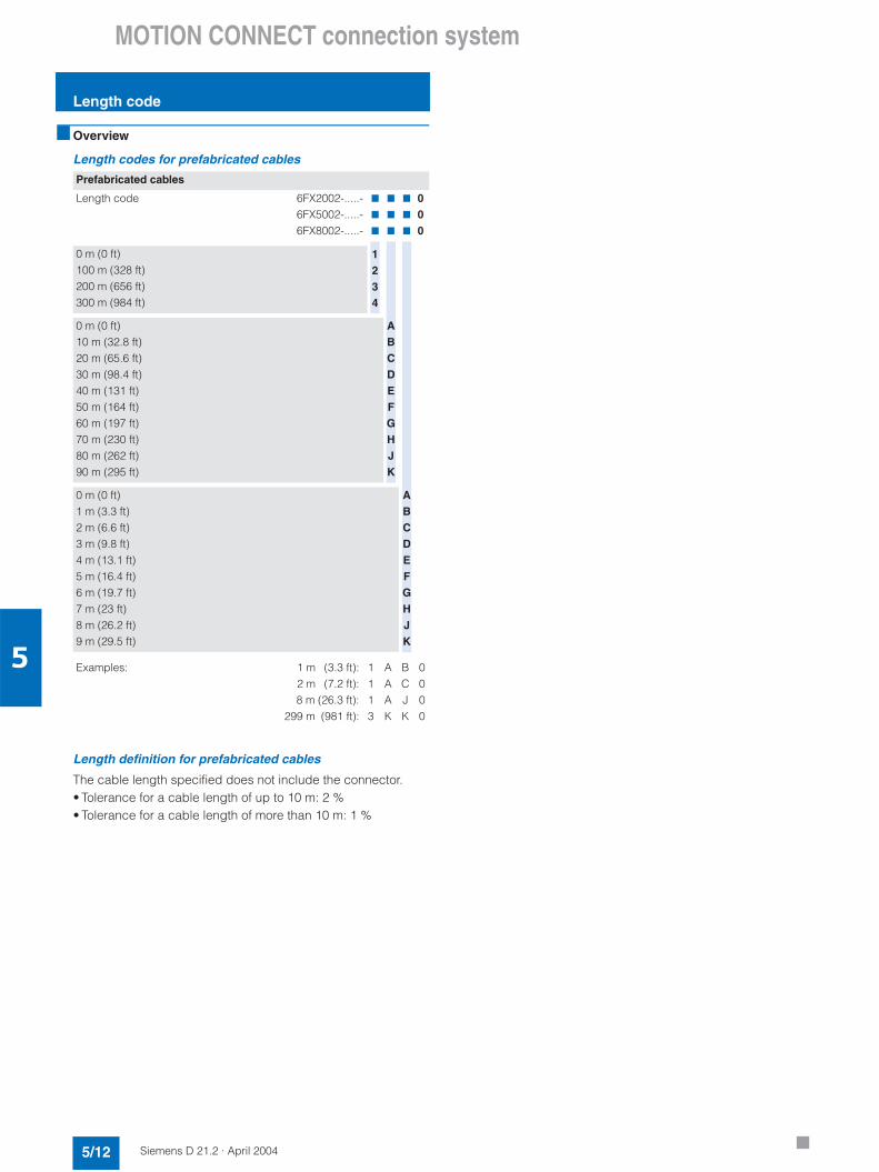
MOTION CONNECT connection system
Length code
5/12 Siemens D 21.2 · April 2004
5
Overview
Length codes for prefabricated cables
Length definition for prefabricated cables
The cable length specified does not include the connector.• Tolerance for a cable length of up to 10 m: 2 %• Tolerance for a cable length of more than 10 m: 1 %
Prefabricated cables
Length code 6FX2002-.....-6FX5002-.....-6FX8002-.....-
7
7
7
7
7
7
7
7
7
000
0 m (0 ft)100 m (328 ft)200 m (656 ft)300 m (984 ft)
0 m (0 ft)10 m (32.8 ft)20 m (65.6 ft)30 m (98.4 ft)40 m (131 ft)50 m (164 ft)60 m (197 ft)70 m (230 ft)80 m (262 ft)90 m (295 ft)
0 m (0 ft)1 m (3.3 ft)2 m (6.6 ft)3 m (9.8 ft)4 m (13.1 ft)5 m (16.4 ft)6 m (19.7 ft)7 m (23 ft)8 m (26.2 ft)9 m (29.5 ft)
Examples: 1 m (3.3 ft):2 m (7.2 ft):8 m (26.3 ft):
299 m (981 ft):
1113
AAAK
BCJK
0000
1234
ABCDEFGHJK
ABCDEFGHJK
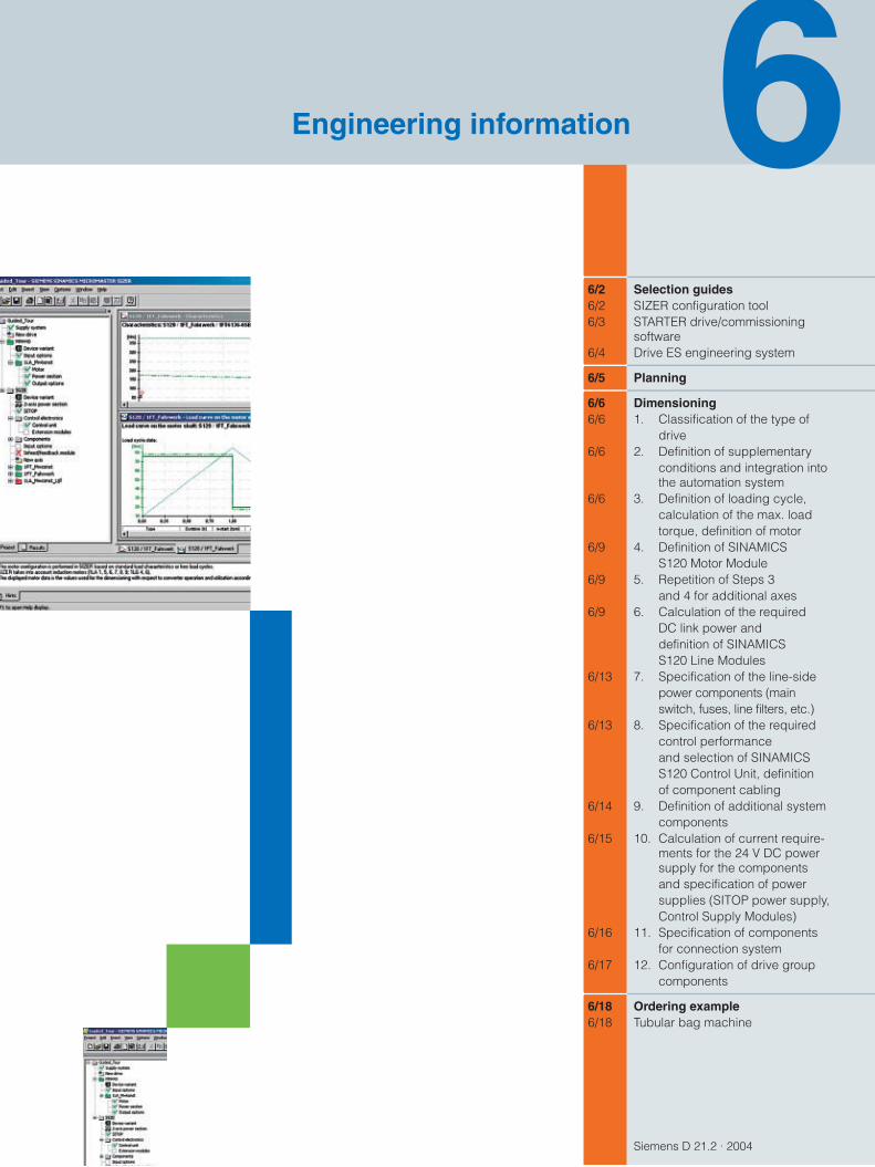
Siemens D 21.2 · 2004
6/2 Selection guides6/2 SIZER configuration tool6/3 STARTER drive/commissioning
software6/4 Drive ES engineering system
6/5 Planning
6/6 Dimensioning6/6 1. Classification of the type of
drive6/6 2. Definition of supplementary
conditions and integration intothe automation system
6/6 3. Definition of loading cycle,calculation of the max. loadtorque, definition of motor
6/9 4. Definition of SINAMICSS120 Motor Module
6/9 5. Repetition of Steps 3and 4 for additional axes
6/9 6. Calculation of the requiredDC link power anddefinition of SINAMICSS120 Line Modules
6/13 7. Specification of the line-sidepower components (mainswitch, fuses, line filters, etc.)
6/13 8. Specification of the requiredcontrol performanceand selection of SINAMICSS120 Control Unit, definitionof component cabling
6/14 9. Definition of additional systemcomponents
6/15 10. Calculation of current require-ments for the 24 V DC powersupply for the componentsand specification of power supplies (SITOP power supply,Control Supply Modules)
6/16 11. Specification of componentsfor connection system
6/17 12. Configuration of drive groupcomponents
6/18 Ordering example6/18 Tubular bag machine
Engineering information
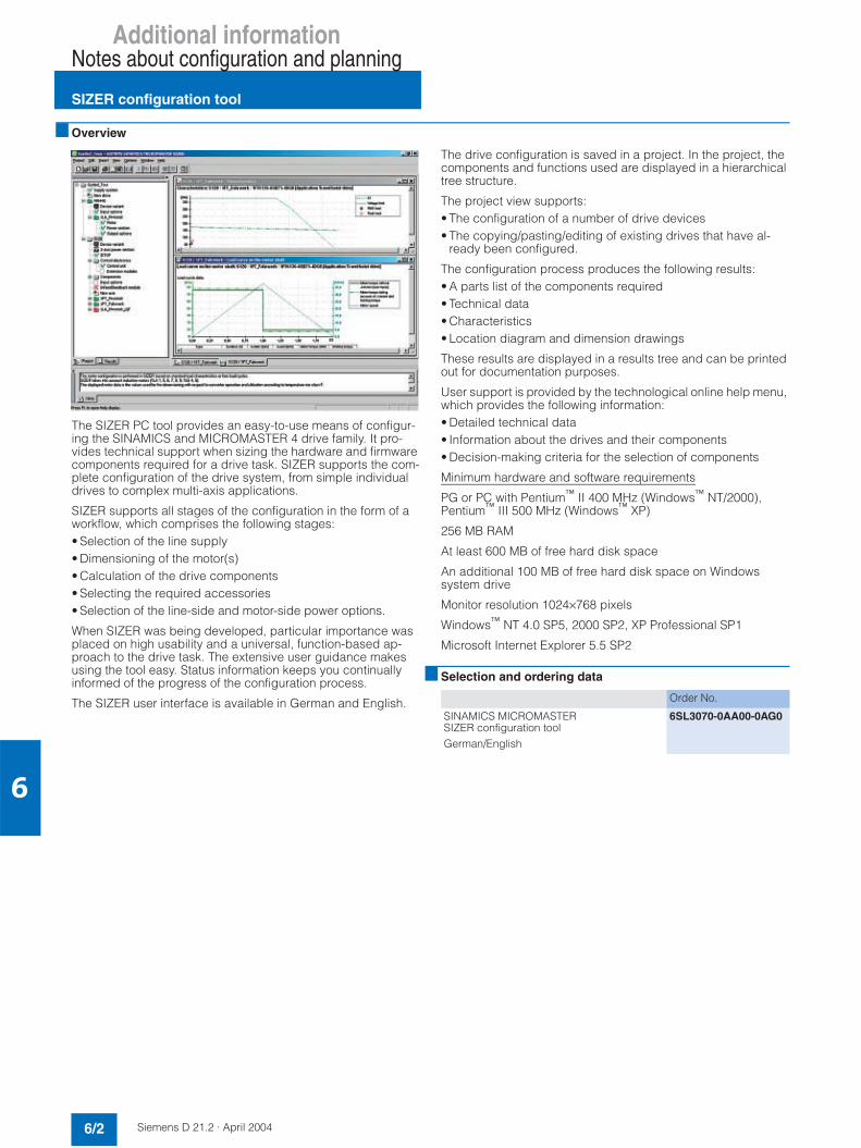
Additional informationNotes about configuration and planning
SIZER configuration tool
6/2 Siemens D 21.2 · April 2004
6
Overview
The SIZER PC tool provides an easy-to-use means of configur-ing the SINAMICS and MICROMASTER 4 drive family. It pro-vides technical support when sizing the hardware and firmware components required for a drive task. SIZER supports the com-plete configuration of the drive system, from simple individual drives to complex multi-axis applications.
SIZER supports all stages of the configuration in the form of a workflow, which comprises the following stages:• Selection of the line supply• Dimensioning of the motor(s)• Calculation of the drive components• Selecting the required accessories• Selection of the line-side and motor-side power options.
When SIZER was being developed, particular importance wasplaced on high usability and a universal, function-based ap-proach to the drive task. The extensive user guidance makesusing the tool easy. Status information keeps you continually informed of the progress of the configuration process.
The SIZER user interface is available in German and English.
The drive configuration is saved in a project. In the project, thecomponents and functions used are displayed in a hierarchicaltree structure.
The project view supports:• The configuration of a number of drive devices• The copying/pasting/editing of existing drives that have al-
ready been configured.
The configuration process produces the following results:• A parts list of the components required• Technical data• Characteristics• Location diagram and dimension drawings
These results are displayed in a results tree and can be printed out for documentation purposes.
User support is provided by the technological online help menu, which provides the following information:• Detailed technical data• Information about the drives and their components• Decision-making criteria for the selection of components
Minimum hardware and software requirements
PG or PC with Pentium™ II 400 MHz (Windows™ NT/2000),Pentium™ III 500 MHz (Windows™ XP)
256 MB RAM
At least 600 MB of free hard disk space
An additional 100 MB of free hard disk space on Windows system drive
Monitor resolution 1024×768 pixels
Windows™ NT 4.0 SP5, 2000 SP2, XP Professional SP1
Microsoft Internet Explorer 5.5 SP2
Selection and ordering data
Order No.
SINAMICS MICROMASTER SIZER configuration toolGerman/English
6SL3070-0AA00-0AG0

Additional informationNotes about configuration and planning
STARTER drive/commissioning software
6/3Siemens D 21.2 · April 2004
6
Overview
The easy-to-use STARTER drive/commissioning software can be used to:• start up• optimize and• diagnose.
This software can be operated either as a stand-alone PC appli-cation or can be integrated into the SCOUT engineering system (SIMOTION). The basic functions and handling are the same in both cases.
In addition to the SINAMICS drives, the current version ofSTARTER also supports MICROMASTER 4 drives.
The project wizards can be used to create the drives within the structure of the project tree.
First-time users are supported by solution-based dialog menu,with a standard graphics-based display maximizing clarity when setting the drive parameters.
First commissioning is guided by wizards, which make all the ba-sic settings in the drive. This enables a drive to be up and run-ning after only setting a small number of parameters within the drive configuration process.
The individual settings required are made using graphics-based parameterization screenforms, which also display the mode ofoperation.
Examples of individual settings that can be made include:• Terminals• Bus interface• Setpoint channel (e.g. fixed setpoints)• Speed control (e.g. ramp-function generator, limits)• BICO interconnections• Diagnostics.
Experts can gain rapid access to the individual parameters via the Expert List and do not have to navigate dialogs.
In addition, the following functions are available for optimizationpurposes:• Self-optimization• Trace.
Diagnostics functions provide information about:• Control/status words• Parameter status• Operating conditions• Communication states.
Performance• Easy to use: Only a small number of settings need to be made
for successful first commissioning: axis turning• Solution-based dialog-based user guidance simplifies com-
missioning• Self-optimization functions reduce manual effort for optimiza-
tion• The built-in trace function provides optimum support during
commissioning, optimization and troubleshooting.
Minimum hardware and software requirements
PG or PC with Pentium™ II 400 MHz (Windows™ NT/2000),Pentium™ III 500 MHz (Windows™ XP)
256 MB RAM
Monitor resolution 1024×768 pixels
Windows™ NT 4.0 SP6, 2000 SP3, XP Professional SP1
Microsoft Internet Explorer 5.01
Selection and ordering data
Order No.
STARTER commissioning tool for SINAMICS and MICROMASTERGerman/English
6SL3072-0AA00-0AG0

Additional informationNotes about configuration and planning
Drive ES engineering system
6/4 Siemens D 21.2 · April 2004
6
Overview
Drive ES is the engineering system used to integrate Siemens drive technology into the SIMATIC automation world easily, effi-ciently and cost-effectively in terms of communication, configu-ration and data management. The STEP 7 Manager user inter-face provides the basis for this procedure.
Various software packages are available for SINAMICS S:• Drive ES Basic
for first-time users to the world of Totally Integrated Automation and the option for routing beyond network limits and the use of the SIMATIC teleservice.Drive ES Basic is the basic software program for setting the pa-rameters of all drives online and offline.Drive ES Basic enables both the automation system and the drives to be handled via the SIMATIC Manager user interface. Drive ES Basic is the starting point for common data archiving complete projects and for extending the use of the SIMATIC teleservice to drives. Drive ES Basic provides the configuration tools for the new motion control functions slave-to-slave com-munication, equidistance and isochronous operation with PROFIBUS DP.
• Drive ES SIMATICSimply parameterize the STEP 7 communication instead of programming.In order to use Drive ES SIMATIC, STEP 7 must be installed. It features a SIMATIC function block library, making the program-ming of the PROFIBUS interface in the SIMATIC-CPU for the drives easy and secure.There is no need for separate, time-consuming programming of the data exchange between the SIMATIC-CPU and the drive.All Drive ES users need to remember is:Copy – Modify – Download – Ready.Customized, fully-developed function blocks are copied from the library into user-specific projects.Frequently-used functions are set to run in program format: - Read out complete diagnostics buffer automatically from the
drive- Download complete parameter set automatically from the
SIMATIC CPU to the drive, e.g. in the event of a device being replaced
- Load part parameter sets (e.g. in the event of a recipe or product replacement) automatically from the SIMATIC-CPU
- Read back, i.e. update, complete parameterization or part parameter sets from the drive to the SIMATIC-CPU
• Drive ES PCS 7integrates drives with the PROFIBUS interface into the SIMATIC PCS 7 process control system.Drive ES PCS 7 can only be used with SIMATIC PCS 7 Version 5.0 and higher. Drive ES PCS 7 provides a function block library with function blocks for the drives and the corre-sponding faceplates for the operator station, which enables the drives to be operated from the PCS 7 process control system.
For further information please visit us on the Internet at:
http://www.siemens.com/drivesolutions
Selection and ordering data
<(54
5
4( 42-3(-
'
Order No.
Drive ES Basic V 5.3• Configuration software for the integration of
drives into Totally Integrated Automation• Requirement: STEP 7 V 5.1 and higher, SP 3• Supply format: CD-ROM
Ger., Eng., Fr., Sp., It.with electronic documentation
Single license 6SW1700-5JA00-3AA0
Multi-user license, 60x 6SW1700-5JA00-3AA1
Update service for single-user license 6SW1700-0JA00-0AB2
Update service for multi-user license 6SW1700-0JA00-1AB2
Upgrade from V 5.x to V 5.3 6SW1700-5JA00-3AA4
Drive ES SIMATIC V 5.3• Function block library for SIMATIC
for the parameterization of communicationwith the drives
• Requirement: STEP 7 V 5.1 and higher, SP 3• Supply format: CD-ROM
Ger., Eng., Fr., Sp., It.with electronic documentation
Single-user license incl. 1 x runtime license 6SW1700-5JC00-3AA0
Runtime license 6SW1700-5JC00-1AC0
Update service for single-user license 6SW1700-0JC00-0AB2
Upgrade from V 5.x to V 5.3 6SW1700-5JC00-3AA4
Drive ES PCS 7 V 6.0• Function block library for PCS 7
for the integration of drives• Requirement: PCS 7 V 6.0 and higher• Supply format: CD-ROM
Ger., Eng., Fr., Sp., It.with electronic documentation
Single-user license incl. 1 x runtime license 6SW1700-6JD00-0AA0
Runtime license 6SW1700-5JD00-1AC0
Update service for single-user license 6SW1700-0JD00-0AB2
Upgrade from V 5.x to V 6.x 6SW1700-6JD00-0AA4

Additional informationNotes about configuration and planning
Planning
6/5Siemens D 21.2 · April 2004
6
Overview
Motion Control
Servo drives are ideal for executing motion control tasks. They execute linear or rotary movements within a defined movement cycle. All movements must be optimized in terms of duration.
In light of these considerations, servo drives must meet the fol-lowing requirements:• High dynamic response, i.e. short rise times• Overload-capable, i.e. high acceleration reserve• Wide range, i.e. high resolution for precise positioning
The following configuration is valid for synchronous and asyn-chronous motors.
General configuration sequence
The function description of the machine provides the basis for the configuration. The definition of the components is based on physical dependencies and is usually carried out as follows:
Step Description of configuration activity
1. Clarification of type of application
2. Definition of supplementary conditions and integration into automated system
3. Definition of load cycle, calculation of max. load torque,definition of motor
4. Definition of SINAMICS S120 Motor Module
5. Repeat Steps 3 and 4 for additional axes
6. Calculation for the required DC link power and definition of the SINAMICS S120 Line Module
7. Specification of the line-side options (main switch, fuses, linefilters, etc.)
8. Specification of the required control performance and selec-tion of the SINAMICS S120 Control Unit, definition of compo-nent cabling
9. Definition of additional system components
10. Calculation of the current requirements for the 24 V DC supply for the components and specification of power supplies (SITOP power supply, Control Supply Modules)
11. Specification of components for connection system
12. Configuration of drive group components
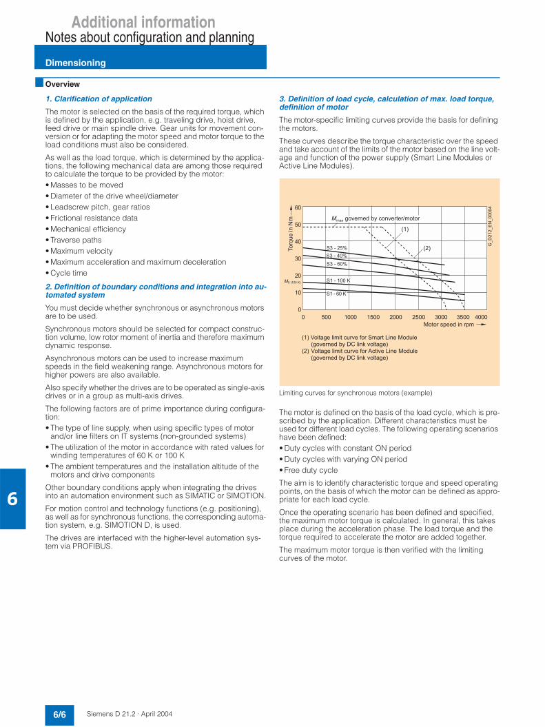
Additional informationNotes about configuration and planning
Dimensioning
6/6 Siemens D 21.2 · April 2004
6
Overview
1. Clarification of application
The motor is selected on the basis of the required torque, which is defined by the application, e.g. traveling drive, hoist drive, feed drive or main spindle drive. Gear units for movement con-version or for adapting the motor speed and motor torque to the load conditions must also be considered.
As well as the load torque, which is determined by the applica-tions, the following mechanical data are among those required to calculate the torque to be provided by the motor:• Masses to be moved• Diameter of the drive wheel/diameter• Leadscrew pitch, gear ratios• Frictional resistance data• Mechanical efficiency• Traverse paths• Maximum velocity• Maximum acceleration and maximum deceleration• Cycle time
2. Definition of boundary conditions and integration into au-tomated system
You must decide whether synchronous or asynchronous motorsare to be used.
Synchronous motors should be selected for compact construc-tion volume, low rotor moment of inertia and therefore maximum dynamic response.
Asynchronous motors can be used to increase maximum speeds in the field weakening range. Asynchronous motors for higher powers are also available.
Also specify whether the drives are to be operated as single-axis drives or in a group as multi-axis drives.
The following factors are of prime importance during configura-tion:• The type of line supply, when using specific types of motor
and/or line filters on IT systems (non-grounded systems)• The utilization of the motor in accordance with rated values for
winding temperatures of 60 K or 100 K• The ambient temperatures and the installation altitude of the
motors and drive components
Other boundary conditions apply when integrating the drives into an automation environment such as SIMATIC or SIMOTION.
For motion control and technology functions (e.g. positioning), as well as for synchronous functions, the corresponding automa-tion system, e.g. SIMOTION D, is used.
The drives are interfaced with the higher-level automation sys-tem via PROFIBUS.
3. Definition of load cycle, calculation of max. load torque, definition of motor
The motor-specific limiting curves provide the basis for defining the motors.
These curves describe the torque characteristic over the speed and take account of the limits of the motor based on the line volt-age and function of the power supply (Smart Line Modules or Active Line Modules).
Limiting curves for synchronous motors (example)
The motor is defined on the basis of the load cycle, which is pre-scribed by the application. Different characteristics must beused for different load cycles. The following operating scenarios have been defined:• Duty cycles with constant ON period• Duty cycles with varying ON period• Free duty cycle
The aim is to identify characteristic torque and speed operating points, on the basis of which the motor can be defined as appro-priate for each load cycle.
Once the operating scenario has been defined and specified, the maximum motor torque is calculated. In general, this takes place during the acceleration phase. The load torque and the torque required to accelerate the motor are added together.
The maximum motor torque is then verified with the limiting curves of the motor.
"
%
&
& & %
&)*
&)%*
&)"*
)C
)"C
!C#
!#
!#F
+
.-5+ >(53
!#,-(529+!-5+ >4A5-#
!# ,-(52 (59+!-5+ >4A5-#
%

Additional informationNotes about configuration and planning
Dimensioning
6/7Siemens D 21.2 · April 2004
6
The following criteria must be taken into account when defining the motor:• The dynamic limits must be observed, i.e. all speed-torque
points of the load cycle must lie below the relevant limiting curve.
• The thermal limits must be observed, i.e. with synchronous mo-tors, the rms motor torque at the average motor speed resulting from the duty cycle must lie below the S1 curve (continuous duty). With asynchronous motors, the rms value of the motor current within a duty cycle must be less than the rated motor current.
• It should be noted that the maximum permissible motor torque on synchronous motors at higher speeds is reduced as a result of the voltage limiting curve. In addition, a clearance of 10% from the voltage limiting curve should be observed to safe-guard against voltage fluctuations.
• When using asynchronous motors, the permissible motor torque in the field weakening range is reduced as a result of thestability limit. A clearance of 30% should be observed.
• When using an absolute encoder, the rated torque of the motor is reduced by 10% due to the thermal limits of the encoder.
Duty cycles with constant ON period
Duty cycles with constant ON period place specific require-ments on the torque characteristic as a function of the speed, e.g. M = constant, M ~ n2, M ~ n or P = constant.
These drives typically work at a stationary operating point. Base load dimensioning is applied. The base load torque must lie be-low the S1 curve.
In the event of transient overloads (e.g. during start-up), over-load dimensioning is applied. The peak torque must lie belowthe voltage limiting curve on synchronous motors or below thestability limit on asynchronous motors.
In summary, the dimensioning is as follows:
Selection of motors for duty cycles with constant ON period (example)
Duty cycles with varying ON period
As well as continuous duty (S1), standardized periodic dutytypes (S3) are also defined for duty cycles with varying ON peri-ods. S3 duty is operation which comprises a sequence of similar cycles, each of which comprises a time with constant load and a break.
S1 duty (continuous operation)
S3 duty (periodic duty without affecting the start-up procedure)
Fixed variables are usually used for the relative ON period:• S3 – 60%• S3 – 40%• S3 – 25%
Corresponding motor characteristics are provided for these specifications. The load torque must lie below the correspond-ing thermal limiting curve of the motor. Overload dimensioning is taken into account for duty cycles with varying ON periods.
"
%
&
& & %
!C#
!#
!#F
+
6(/! (+#
6(/!5+#
.-5+ >(53
!#,-(529+!-5+ >4A5-#
!# ,-(52 (59+!-5+ >4A5-#
5
..
.
5
.
9 <
..$9
< <
6?
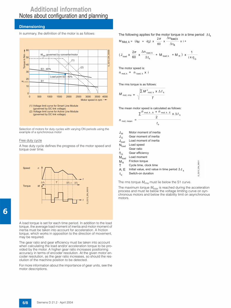
Additional informationNotes about configuration and planning
Dimensioning
6/8 Siemens D 21.2 · April 2004
6
In summary, the definition of the motor is as follows:
Selection of motors for duty cycles with varying ON periods using the example of a synchronous motor
Free duty cycle
A free duty cycle defines the progress of the motor speed and torque over time.
A load torque is set for each time period. In addition to the load torque, the average load moment of inertia and motor moment of inertia must be taken into account for acceleration. A friction torque, which works in opposition to the direction of movement, may be required.
The gear ratio and gear efficiency must be taken into accountwhen calculating the load and/or acceleration torque to be pro-vided by the motor. A higher gear ratio increases positioningaccuracy in terms of encoder resolution. At the given motor en-coder resolution, as the gear ratio increases, so should the res-olution of the machine position to be detected.
For more information about the importance of gear units, see the motor descriptions.
The rms torque Mrms must lie below the S1 curve.
The maximum torque Mmax is reached during the accelerationprocess and must lie below the voltage limiting curve on syn-chronous motors and below the stability limit on asynchronous motors.
"
%
&
& & %
&)%*
!C#
!#
!#F
+
9+&)%*
.-5+ >(53
!#,-(529+!-5+ >4A5-#
!# ,-(52 (59+!-5+ >4A5-#
"
)
+
F
82-28F+A
8+G
8F2G
8+((+2G
@ 6@A A.
@A 6 +@A .
@A@ @A@?
@ 6
.
A
@A !H H#?6 . . ."
?A
+@A
H
H+
H
+
+
1I
! H+
.A"
. +@A 1? ? .
+@A.
#
229+29++22((>9+;(F4>(@((A5@+5+(8)+
A

Additional informationNotes about configuration and planning
Dimensioning
6/9Siemens D 21.2 · April 2004
6
In summary, the dimensioning is as follows:
Selection of motors on the basis of a free duty cycle (example)
Motor selection
It is now possible to identify a motor that exactly matches oper-ating conditions.
In a following step, a check is made as to whether the thermal limits are maintained. For this purpose, the motor current at base load must be calculated. For configuration based on duty cycle with constant ON period with overload, the overload current based on the required overload torque must be calculated. The calculation rules for this purpose depend on the type of motor used (synchronous motor, asynchronous motor) and the operat-ing scenario (duty cycles with constant ON period, duty cycles with varying ON period, free duty cycle).
Finally, the other characteristics of the motor must be defined. This is done by configuring the motor options (see motor de-scription).
4. Definition of SINAMICS S120 Motor Module
The Motor Modules can be assigned to the motor on the basis of their rated output and peak current. The Motor Module is as-signed on the basis of the static current I0 100K (rated current for winding temperature 100 K) for synchronous motors and the rated current Irated for asynchronous motors, and is listed in the motor description.
For an optimum configuration, the motor current calculated is mapped to the Motor Module. The precise calculation is sup-ported by SIZER.
Depending on the ambient conditions (installation altitude, am-bient temperature), the output current of the motor modules may need to be reduced (see component description).
The motor current calculated on the basis of the motor type (syn-chronous motor, asynchronous motor) and the operating sce-nario (duty cycles with constant ON period, duty cycles with varying ON period, free duty cycle) is used to dimension the Mo-tor Module:
Irated, motor module ≥ Iload
An increased output current may be requested from the Motor Modules for a specific period of time. In the event of an overload configuration, the following must be true:
Irated, Motor Module × overload factor < Ioverload
Overload factor = Ratio Irated/Imax, taking into account the dutycycles (see component descriptions).
The Motor Modules can be supplied as Single Motor Modules and, in certain current ranges, also as Double Motor Modules.
5. Repeat Steps 3 and 4 for additional axes
The motors and Motor Modules must be calculated for all axes.
6. Calculation for the required DC link power and definitionof the SINAMICS S120 Line Module
In multi-axis drive applications, a number of Motor Modules areoperated on a common DC link, which is supplied with power by a line module.
Now define whether a Smart Line Module or an Active Line Mod-ule is to be used. This depends on the available power ranges of the Line Modules and on whether the DC link voltage needs to be non-regulated and therefore line-voltage-dependent (Smart Line Module) or regulated (Active Line Module) at a constant DC link voltage of 600 V or 625 V (depending on the line voltage, up to 3 AC 415 V → DC 600 V, 3 AC 416 V to 440 V → DC 625 V, above 3 AC 440 V → line-voltage-dependent).
The power required for each axis are taken into account when defining the Line Module.
"
%
&
& & %
!#
!#
!C#
F .-5+ >(53
(A(5
.!2(A(5#
+
!#,-(529+!-5+ >4A5-#
!# ,-(52 (59+!-5+ >4A5-#
'

Additional informationNotes about configuration and planning
Dimensioning
6/10 Siemens D 21.2 · April 2004
6
The operating scenario and the type of motor must be taken into account when calculating the required DC link power:• With asynchronous motors, which are dimensioned for duty cy-
cles with varying ON period, the rated power of the motor is equal to the required DC link power.
• With synchronous motors, which are dimensioned for duty cy-cles with varying ON period, the required DC link power is equal to the calculated power × speed ratio. The required DClink power can be influenced via the speed ratio (ratio of loadspeed to rated speed). Empirical values for the speed ratio are:
• For asynchronous motors and synchronous motors, which are dimensioned on the basis of duty cycles with constant ON pe-riod or free duty cycle respectively, the power at the operating point of the motor or the rms power taking into account the ef-ficiency of the motor and Motor Module is applied as the re-quired DC link power.
The total of the Pcalc ratings for the individual motors, corrected by the coincidence factor and the average speed ratio, provides the basis for the selection of the Line Module type rating.
Calculated power for synchronous motors
Pcalc VSA = 0.105 × M0 × nrated × 10-3
Pcalc VSA = Calculated power for synchronous motors in kW
0.105 = Factor 2 × π/60
M0 = Static torque in Nm
nrated = Rated speed in rpm
Calculated power for asynchronous motors• Motors < 4 kW (5.4 HP)
Pcalc HSA = 1.45 × Pmotor shaft HSA
• Motors > 4 kW (5.4 HP)
Pcalc HSA = 1.25 × Pmotor shaft HSA
Pcalc HSA = DC link power for constant-power drive in kW
1.45 or 1.25 = Factor taking into account the efficiency of the mo-tor
Pmotor shaft HSA = Mechanical power used on the motor shaft in kW
The rated incoming power supply for the line modules is basedon a line voltage of 380 V. If the line voltage changes, this mayaffect the output power of the line modules. However, it cannot exceed the rated power.
Depending on the ambient conditions (installation altitude, am-bient temperature), the rated incoming power supply of the line modules may need to be reduced (see component description).
To optimize the dimensioning of the Line Module, the cyclic char-acteristics of the torque must be taken into account for the indi-vidual axes. It is assumed that asynchronous motors are used as main drives/main spindle drives and are therefore in constant long-term operation. Synchronous motors are used for cyclic se-quences (e.g. feed axes) – they do not run constantly.
The coincidence factor takes into account the cyclic character-istic of the torque for each individual axis.
Empirical values for the coincidence factor are:
To prevent misconfigurations on axes with very different powerratings, the axes are categorized in power classes on the basis of their power.
These classes can be used as a basis for dimensioning the LineModule in accordance with the following procedure:
This scheme is reflected in the configuration table below.
Application Speed ratio ñ/nrated
Synchronous motors/feed drivesfor low-speed drives
0.4 to 0.7
Robot drivesfor high-speed drives
0.9 to 1
Asynchronous/main spindle driveswith 1FT and 1PH7 motors
1
Feed axes per range Coincidence factor K per range
1 1
2 0.63
3 0.5
4 0.38
5 0.33
6 0.28
1F+4A++2(8.!A-((8+@
2F+#
.(-J+((+-(
>2(+2(8(+8F+4A++2(8(
F+4A++
(29+A-((8>5-+ (+
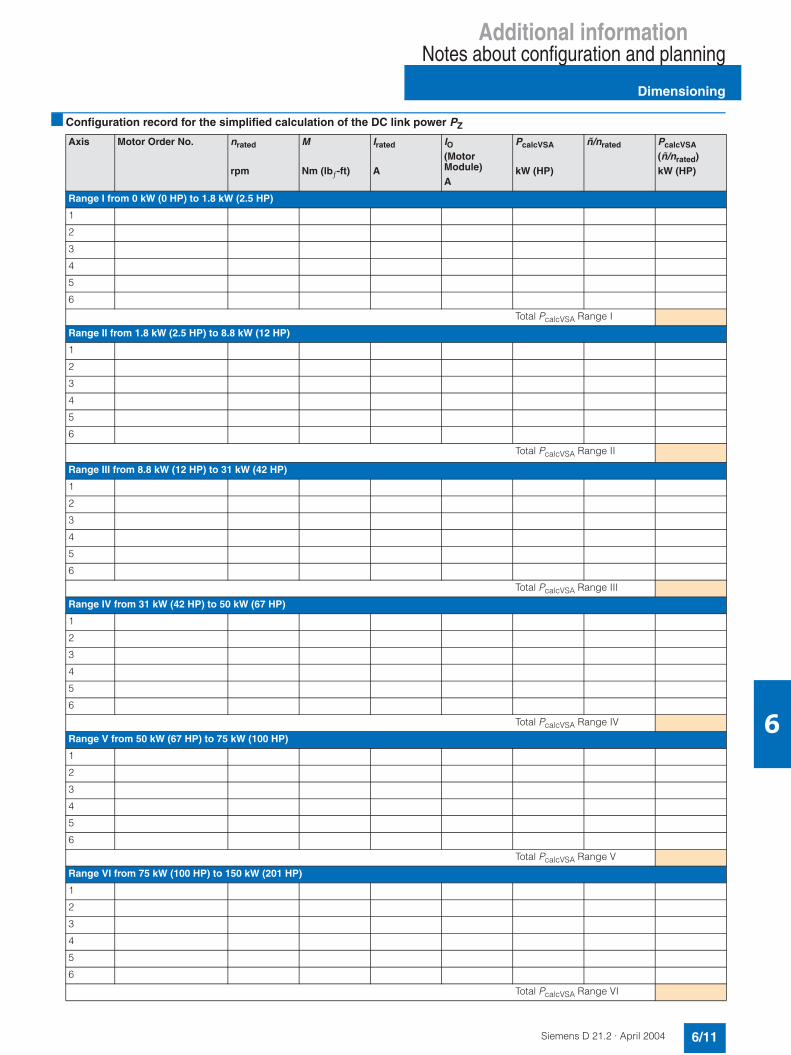
Additional informationNotes about configuration and planning
Dimensioning
6/11Siemens D 21.2 · April 2004
6
Configuration record for the simplified calculation of the DC link power PZ
Axis Motor Order No. nrated
rpm
M
Nm (lbƒ-ft)
Irated
A
IO(MotorModule)A
PcalcVSA
kW (HP)
ñ/nrated PcalcVSA
(ñ/nrated)kW (HP)
Range I from 0 kW (0 HP) to 1.8 kW (2.5 HP)
1
2
3
4
5
6
Total PcalcVSA Range I
Range II from 1.8 kW (2.5 HP) to 8.8 kW (12 HP)
1
2
3
4
5
6
Total PcalcVSA Range II
Range III from 8.8 kW (12 HP) to 31 kW (42 HP)
1
2
3
4
5
6
Total PcalcVSA Range III
Range IV from 31 kW (42 HP) to 50 kW (67 HP)
1
2
3
4
5
6
Total PcalcVSA Range IV
Range V from 50 kW (67 HP) to 75 kW (100 HP)
1
2
3
4
5
6
Total PcalcVSA Range V
Range VI from 75 kW (100 HP) to 150 kW (201 HP)
1
2
3
4
5
6
Total PcalcVSA Range VI
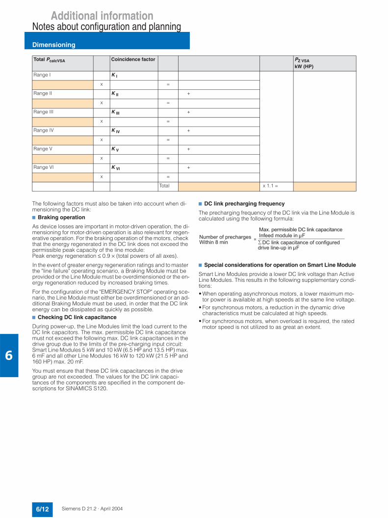
Additional informationNotes about configuration and planning
Dimensioning
6/12 Siemens D 21.2 · April 2004
6
The following factors must also be taken into account when di-mensioning the DC link:7 Braking operation
As device losses are important in motor-driven operation, the di-mensioning for motor-driven operation is also relevant for regen-erative operation. For the braking operation of the motors, check that the energy regenerated in the DC link does not exceed the permissible peak capacity of the line module:Peak energy regeneration ≤ 0.9 × (total powers of all axes).
In the event of greater energy regeneration ratings and to master the "line failure" operating scenario, a Braking Module must be provided or the Line Module must be overdimensioned or the en-ergy regeneration reduced by increased braking times.
For the configuration of the "EMERGENCY STOP" operating sce-nario, the Line Module must either be overdimensioned or an ad-ditional Braking Module must be used, in order that the DC link energy can be dissipated as quickly as possible.7 Checking DC link capacitance
During power-up, the Line Modules limit the load current to the DC link capacitors. The max. permissible DC link capacitance must not exceed the following max. DC link capacitances in thedrive group due to the limits of the pre-charging input circuit:Smart Line Modules 5 kW and 10 kW (6.5 HP and 13.5 HP) max. 6 mF and all other Line Modules 16 kW to 120 kW (21.5 HP and 160 HP) max. 20 mF.
You must ensure that these DC link capacitances in the drivegroup are not exceeded. The values for the DC link capaci-tances of the components are specified in the component de-scriptions for SINAMICS S120.
7 DC link precharging frequency
The precharging frequency of the DC link via the Line Module is calculated using the following formula:
7 Special considerations for operation on Smart Line Module
Smart Line Modules provide a lower DC link voltage than Active Line Modules. This results in the following supplementary condi-tions:• When operating asynchronous motors, a lower maximum mo-
tor power is available at high speeds at the same line voltage.• For synchronous motors, a reduction in the dynamic drive
characteristics must be calculated at high speeds.• For synchronous motors, when overload is required, the rated
motor speed is not utilized to as great an extent.
Total PcalcVSA Coincidence factor PZ VSA
kW (HP)
Range I K I
x =
Range II K II +
x =
Range III K III +
x =
Range IV K IV +
x =
Range V K V +
x =
Range VI K VI +
x =
Total x 1.1 =
6 2(8-78
./ 4A(((2++;4A(((2(2-++5);
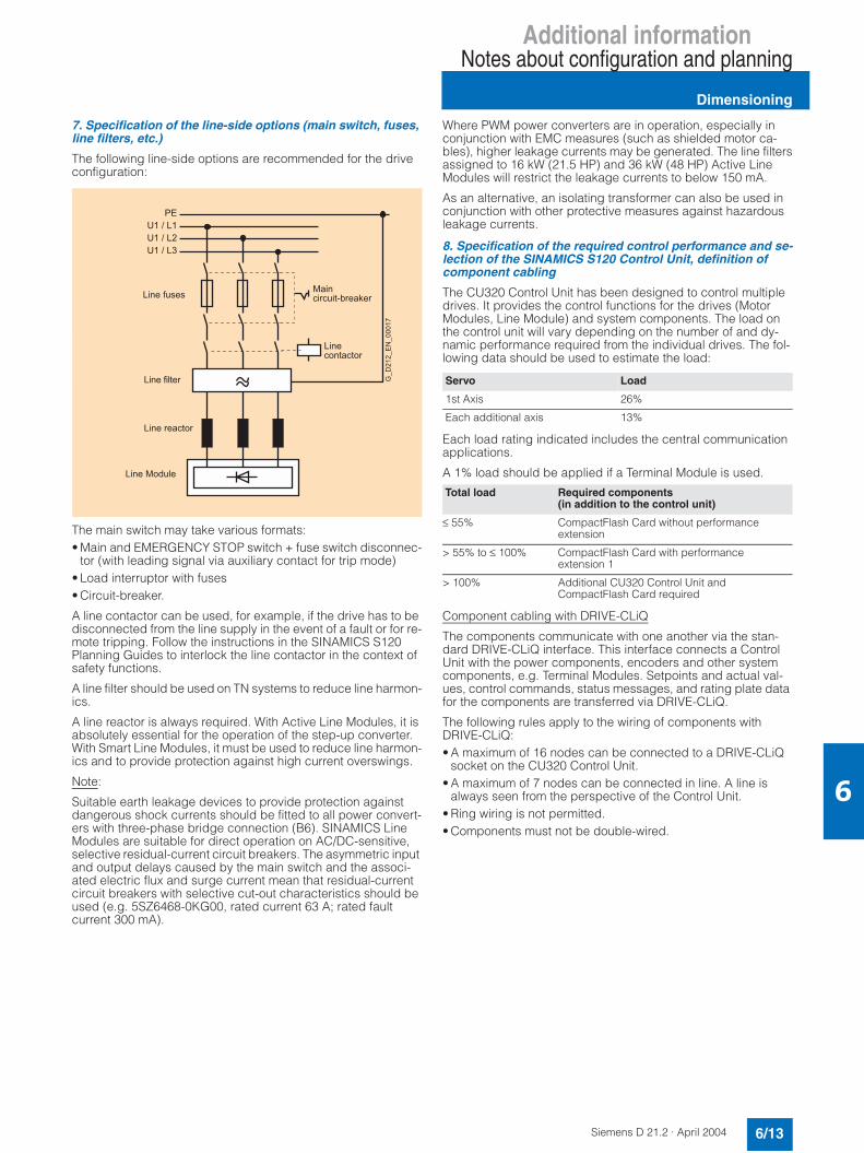
Additional informationNotes about configuration and planning
Dimensioning
6/13Siemens D 21.2 · April 2004
6
7. Specification of the line-side options (main switch, fuses, line filters, etc.)
The following line-side options are recommended for the drive configuration:
The main switch may take various formats:• Main and EMERGENCY STOP switch + fuse switch disconnec-
tor (with leading signal via auxiliary contact for trip mode)• Load interruptor with fuses• Circuit-breaker.
A line contactor can be used, for example, if the drive has to be disconnected from the line supply in the event of a fault or for re-mote tripping. Follow the instructions in the SINAMICS S120 Planning Guides to interlock the line contactor in the context ofsafety functions.
A line filter should be used on TN systems to reduce line harmon-ics.
A line reactor is always required. With Active Line Modules, it is absolutely essential for the operation of the step-up converter. With Smart Line Modules, it must be used to reduce line harmon-ics and to provide protection against high current overswings.
Note:
Suitable earth leakage devices to provide protection against dangerous shock currents should be fitted to all power convert-ers with three-phase bridge connection (B6). SINAMICS LineModules are suitable for direct operation on AC/DC-sensitive, selective residual-current circuit breakers. The asymmetric input and output delays caused by the main switch and the associ-ated electric flux and surge current mean that residual-currentcircuit breakers with selective cut-out characteristics should be used (e.g. 5SZ6468-0KG00, rated current 63 A; rated fault current 300 mA).
Where PWM power converters are in operation, especially in conjunction with EMC measures (such as shielded motor ca-bles), higher leakage currents may be generated. The line filtersassigned to 16 kW (21.5 HP) and 36 kW (48 HP) Active LineModules will restrict the leakage currents to below 150 mA.
As an alternative, an isolating transformer can also be used in conjunction with other protective measures against hazardousleakage currents.
8. Specification of the required control performance and se-lection of the SINAMICS S120 Control Unit, definition of component cabling
The CU320 Control Unit has been designed to control multiple drives. It provides the control functions for the drives (Motor Modules, Line Module) and system components. The load on the control unit will vary depending on the number of and dy-namic performance required from the individual drives. The fol-lowing data should be used to estimate the load:
Each load rating indicated includes the central communication applications.
A 1% load should be applied if a Terminal Module is used.
Component cabling with DRIVE-CLiQ
The components communicate with one another via the stan-dard DRIVE-CLiQ interface. This interface connects a Control Unit with the power components, encoders and other systemcomponents, e.g. Terminal Modules. Setpoints and actual val-ues, control commands, status messages, and rating plate data for the components are transferred via DRIVE-CLiQ.
The following rules apply to the wiring of components with DRIVE-CLiQ:• A maximum of 16 nodes can be connected to a DRIVE-CLiQ
socket on the CU320 Control Unit.• A maximum of 7 nodes can be connected in line. A line is
always seen from the perspective of the Control Unit.• Ring wiring is not permitted.• Components must not be double-wired.
=39=39=39&
9+
92
92
(() A
9((
9(
'
Servo Load
1st Axis 26%
Each additional axis 13%
Total load Required components(in addition to the control unit)
≤ 55% CompactFlash Card without performanceextension
> 55% to ≤ 100% CompactFlash Card with performance extension 1
> 100% Additional CU320 Control Unit andCompactFlash Card required

Additional informationNotes about configuration and planning
Dimensioning
6/14 Siemens D 21.2 · April 2004
6
In addition, the motor encoder should be connected to the asso-ciated Motor Module.
Wiring DRIVE-CLiQ components
The following examples illustrate the flexibility of the DRIVE-CLiQ wiring.
Example of a line topology for standard solutions
Example of a tree topology for high-performance solutions, e.g. high-dynamic axes in direct motion control group, selective access to individ-ual axes/axis groupings for maintenance operation, etc.
The power components are supplied with the appropriate DRIVE-CLiQ connecting cable for connection to the adjacent drive module in the line-up (line topology). Prefabricated DRIVE-CLiQ cables in various lengths of up to 100 m (328 ft) are avail-able for connecting motor encoders, direct encoders, Terminal Modules, etc.
9. Definition of additional system components
Sensor Modules
Signal connection for the various encoders (incremental en-coder sin/cos 1 Vpp, absolute encoder, resolver) to the DRIVE-CLIQ interface takes place with Sensor Modules. Depending on the measurement system, SMC10, SMC20 or SMC30 SensorModules can be used. The Sensor Modules are suitable for mounting on DIN rails. They are also used for the signal condi-tioning of external (machine) encoders.
For some motor types, encoder evaluation is integrated as stan-dard in the motors. These motors are wired directly using DRIVE-CLiQ (in addition to the power connection). Conventional signal conditioning is no longer required; neither is a Sensor Module re-quired.
Expansion modules
The CU320 Control Unit features I/O and interfaces for commu-nication. SINAMICS S120 offers the following expansion mod-ules:• TB30 Terminal Board (terminal expansion for plugging into the
option slot on the CU320 Control Unit)• CBC10 Communication Board (drive CANopen interface for
plugging into the option slot on the CU320 Control Unit)• TM31 Terminal Module (terminal expansion for connection via
DRIVE-CLiQ)
The following criteria must be taken into account if you are using the expansion modules:• Only one option board can be plugged into the option slot on
the CU320 Control Unit.• A maximum of 8 Terminal Modules may be operated in a drive
group.
Braking Module
A Braking Module must be used to stop the drives in the event of a line failure or "EMERGENCY STOP", as in these operatingscenarios the braking energy can no longer be regenerated into the line or cannot be regenerated quickly enough.
The Braking Modules can be connected in parallel to increase the braking power.
The maximum number of Braking Modules in a drive group de-pends on the DC link capacitance of the drive configuration in question. One Braking Module can be used for each complete0.5 mF of DC link capacitance.
If the DC link capacitance is not sufficient for the operation of a number of Braking Modules, Capacitor Modules can be used to increase the DC link capacitance. The max. permissible DC link capacitance of a drive group on a Line Module must be taken into account. The max. DC link capacitance to be taken into ac-count for precharging current limiting on the Line Modules arelisted in the technical data for the line modules.
4=&
:&
:
:
:
& % " '
"%
$
&
--
+ -
&
& & 4
4=&
4
.->
81,)49E2(
%
9+
+
+
& &
44=&
4
.->
81,)49E2(
9+
+
+
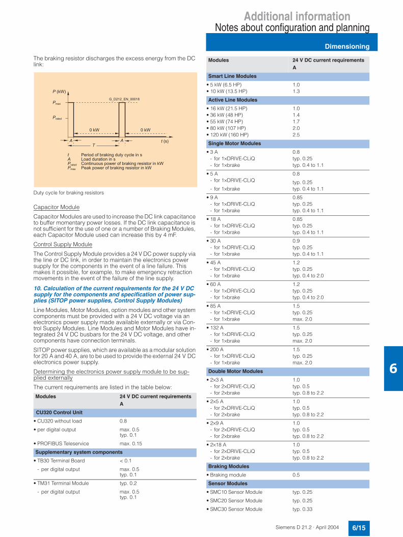
Additional informationNotes about configuration and planning
Dimensioning
6/15Siemens D 21.2 · April 2004
6
The braking resistor discharges the excess energy from the DC link:
Duty cycle for braking resistors
Capacitor Module
Capacitor Modules are used to increase the DC link capacitance to buffer momentary power losses. If the DC link capacitance is not sufficient for the use of one or a number of Braking Modules, each Capacitor Module used can increase this by 4 mF.
Control Supply Module
The Control Supply Module provides a 24 V DC power supply via the line or DC link, in order to maintain the electronics power supply for the components in the event of a line failure. This makes it possible, for example, to make emergency retractionmovements in the event of the failure of the line supply.
10. Calculation of the current requirements for the 24 V DC supply for the components and specification of power sup-plies (SITOP power supplies, Control Supply Modules)
Line Modules, Motor Modules, option modules and other systemcomponents must be provided with a 24 V DC voltage via an electronics power supply made available externally or via Con-trol Supply Modules. Line Modules and Motor Modules have in-tegrated 24 V DC busbars for the 24 V DC voltage, and other components have connection terminals.
SITOP power supplies, which are available as a modular solution for 20 A and 40 A, are to be used to provide the external 24 V DC electronics power supply.
Determining the electronics power supply module to be sup-plied externally
The current requirements are listed in the table below:
Modules 24 V DC current requirementsA
CU320 Control Unit
• CU320 without load 0.8
• per digital output max. 0.5typ. 0.1
• PROFIBUS Teleservice max. 0.15
Supplementary system components
• TB30 Terminal Board < 0.1
- per digital output max. 0.5typ. 0.1
• TM31 Terminal Module typ. 0.2
- per digital output max. 0.5typ. 0.1
!A7#
.
A7
A7
!#
+2 A-+>(>(9++42 A-A7A2 A-A7
+.
+
Smart Line Modules
• 5 kW (6.5 HP) 1.0• 10 kW (13.5 HP) 1.3
Active Line Modules
• 16 kW (21.5 HP) 1.0• 36 kW (48 HP) 1.4• 55 kW (74 HP) 1.7• 80 kW (107 HP) 2.0• 120 kW (160 HP) 2.5
Single Motor Modules
• 3 A 0.8- for 1×DRIVE-CLiQ typ. 0.25- for 1×brake typ. 0.4 to 1.1
• 5 A 0.8- for 1×DRIVE-CLiQ typ. 0.25- for 1×brake typ. 0.4 to 1.1
• 9 A 0.85- for 1×DRIVE-CLiQ typ. 0.25- for 1×brake typ. 0.4 to 1.1
• 18 A 0.85- for 1×DRIVE-CLiQ typ. 0.25- for 1×brake typ. 0.4 to 1.1
• 30 A 0.9- for 1×DRIVE-CLiQ typ. 0.25- for 1×brake typ. 0.4 to 1.1
• 45 A 1.2- for 1×DRIVE-CLiQ typ. 0.25- for 1×brake typ. 0.4 to 2.0
• 60 A 1.2- for 1×DRIVE-CLiQ typ. 0.25- for 1×brake typ. 0.4 to 2.0
• 85 A 1.5- for 1×DRIVE-CLiQ typ. 0.25- for 1×brake max. 2.0
• 132 A 1.5- for 1×DRIVE-CLiQ typ. 0.25- for 1×brake max. 2.0
• 200 A 1.5- for 1×DRIVE-CLiQ typ. 0.25- for 1×brake max. 2.0
Double Motor Modules
• 2×3 A 1.0- for 2×DRIVE-CLiQ typ. 0.5- for 2×brake typ. 0.8 to 2.2
• 2×5 A 1.0- for 2×DRIVE-CLiQ typ. 0.5- for 2×brake typ. 0.8 to 2.2
• 2×9 A 1.0- for 2×DRIVE-CLiQ typ. 0.5- for 2×brake typ. 0.8 to 2.2
• 2×18 A 1.0- for 2×DRIVE-CLiQ typ. 0.5- for 2×brake typ. 0.8 to 2.2
Braking Modules
• Braking module 0.5
Sensor Modules
• SMC10 Sensor Module typ. 0.25
• SMC20 Sensor Module typ. 0.25
• SMC30 Sensor Module typ. 0.33
Modules 24 V DC current requirementsA
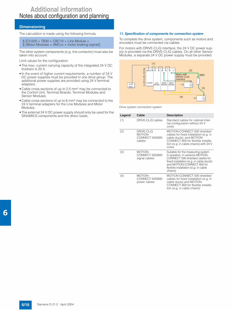
Additional informationNotes about configuration and planning
Dimensioning
6/16 Siemens D 21.2 · April 2004
6
The calculation is made using the following formula:
The other system components (e.g. line contactor) must also be taken into account.
Limit values for the configuration:• The max. current carrying capacity of the integrated 24 V DC
busbars is 20 A.• In the event of higher current requirements, a number of 24 V
DC power supplies must be provided in one drive group. The additional power supplies are provided using 24 V terminal adapters.
• Cable cross-sections of up to 2.5 mm² may be connected to the Control Unit, Terminal Boards, Terminal Modules and Sensor Modules.
• Cable cross-sections of up to 6 mm² may be connected to the 24 V terminal adapters for the Line Modules and Motor Modules.
• The external 24 V DC power supply should only be used for theSINAMICS components and the direct loads.
11. Specification of components for connection system
To complete the drive system, components such as motors and encoders must be connected via cables.
For motors with DRIVE-CLiQ interface, the 24 V DC power sup-ply is provided via the DRIVE-CLiQ cables. On all other Sensor Modules, a separate 24 V DC power supply must be provided.
Drive system connection system
Σ [CU320 + TB30 + CBC10 + Line Module + Σ (Motor Modules + SMCxx + motor braking signal)]
Legend Cable Description
(1) DRIVE-CLiQ cables Standard cables for cabinet-inter-nal configuration without 24 Vcores
(2) DRIVE-CLiQ MOTION-CONNECT 500/800 cables
MOTION-CONNECT 500 shielded cables for fixed installation (e.g. in cable ducts), and MOTION-CONNECT 800 for flexible installa-tion (e.g. in cable chains) with 24 Vcores
(3) MOTION-CONNECT 500/800 signal cables
Suitable for the measuring system in question; in versions MOTION-CONNECT 500 shielded cables for fixed installation (e.g. in cable ducts) and MOTION-CONNECT 800 for flexible installation (e.g. in cable chains)
(4) MOTION-CONNECT 500/800 power cables
MOTION-CONNECT 500 shielded cables for fixed installation (e.g. in cable ducts) and MOTION-CONNECT 800 for flexible installa-tion (e.g. in cable chains)
&
4=&
4
!#
!%#
!#
!&#
81,)49E2(
"
9+
+
+

Additional informationNotes about configuration and planning
Dimensioning
6/17Siemens D 21.2 · April 2004
6
12. Configuration of drive group components
A SINAMICS S drive group comprises a Line Module, Motor modules, DC link components, a Control Unit and the optional expansion modules.
The following criteria must be taken into account when configur-ing the drive group:• The Line Module must always be located on the left as the first
module.• Only one Line Module is permitted in each drive group.• A number of drive groups must be configured for power sup-
plies which cannot be provided by the highest rating.• The Motor Modules must be located next to the Line Module in
descending rated current order from left to right (highest rated current on the left, lowest rated current on the right). Due to the increased currents, Motor Modules with 300 mm (11.8 in) widthhousings have DC link busbars with increased cross-section. Within the drive group, it must be ensured that the DC link bus-bars meet the current carrying capacity requirements for theconnected Motor Modules.
• DC link adapters can be used for multi-tier drive line-ups.• The drive groups should be configured so that the total length
of all power cables (motor cables and line cables) in each in-dividual group, which should preferably be shielded, is≤ 350 m (1148 ft).
Additional criteria for the use of the Braking Module:• The Braking Module is usually located on the right, next to the
smallest Motor Module. This is particularly important in cases in which the drive group comprises a number of very similar Motor Modules.
• In the event of imbalanced power distribution, e.g. if high-power Motor Modules are being used in conjunction with low-power Motor Modules, the Braking Module must be installed between the Motor Modules whose power ratings differ themost, as the cross-sections of the DC link busbars will vary in terms of dimensions due to the current carrying capacity of theintegrated DC link busbars.
Power-based arrangement of Motor Modules
• The Control Unit mounting position is flexible. The following configuration options are possible: - "Docking" on the left-hand side of the Line Module- Direct mounting next to the drive group on a mounting plate- Mounting in other cabinet areas, taking the permissible
DRIVE-CLiQ cable lengths into account.• The following minimum required ventilation spaces for the
components MUST be observed:
Ventilation spaces for booksize format components
Ventilation spaces for Sensor Modules and Terminal Modules
• When mounted on the back panel, line reactors and line filters require a ventilation space of 100 mm (3.9 in) above and below respectively.
D-8
9
%
9+
+ <A-+
4(+
4>+
-2(
=+
4
&
!&/#
!&/#
-2(
4
=+
!/$'#
!/$'#

Additional informationNotes about configuration and planning
Ordering example
6/18 Siemens D 21.2 · April 2004
6
Tubular bag machine
Application description - Technical sequence
Film extractor
The packaging film is paid out from the roll by the feed rollers onthe fill pipe. The material first passes through a dancer roller. The end positions of the dancer roller are recorded. As soon as theend positions are reached, the machine is stopped. The film ad-juster positions the film correctly.
Fill pipe with transport rollers
Next, the film is pulled through the shaping shoulder to create a film tube. This is then transported vertically through the machine via the fill pipe. The transport rollers are responsible for the trans-portation of the film.On films with print logos, the position of the print-mark is perma-nently monitored. Any distortions, such as those caused by stretching of the film, are adjusted by the film feed so that the print logo appears within the appropriate tolerance limits on the package.
Sealing
The tube is sealed by the longitudinal sealer. Heat and pressure are applied during this process. It is important to maintain con-stant sealing times.The machine described here is a continuous duty tubular bag machine. Therefore, the transverse sealing bars follow a curveprofile (similar to a D form).Heat and pressure are also applied during transverse sealing. The transverse sealing mechanism is driven by a servomotor, and follows a series of cyclic motions.
Product feed
If the transverse sealing mechanism is closed when the tube reaches it, the product is filled into the bag via a scale, a propor-tioning screw, or, as in this example, by a proportioning cup. Atthe same time, the bottom of the tube is sealed and the previ-ously filled tube separated.The packages produced by the tubular bag machine are then forwarded to other machines, for example, batch packagers.
General machine control
All relevant machine parameters can be changed during opera-tion or when the machine is at standstill:• Sealing temperature• Switching times for product feed• Bag length• Film adjustment
Visualization
The HMI performs the following functions:• Operation and monitoring• Program storage and recipe management
Touch-panel operation is required
Schematic representation of a tubular bag machine
"#$%
&
'
()#
&*
+,#-#'
(.
&#',/*.#)#
(0

Additional informationNotes about configuration and planning
Ordering example
6/19Siemens D 21.2 · April 2004
6
The following table, which has been derived from the application description, shows how to set up solutions for the major machine functions.
Note:
A single task can be solved in numerous ways. One possible so-lution is shown here. For the sake of transparency, a detailed se-lection of drive systems and connection methods has not been included.
All components must support communication via PROFIBUS DP.
Subsystem Functions/Requirements Solution Order No.
Film extractor Film adjustmentRequires a positioning drive to set the correct position of the film.
1 x intelligent SIMODRIVE POSMO A posi-tioning motor
6SN2132-0AA11-1BA0
Fill pipe with transport rollers Transport rollersThe transport rollers, which aredriven by a servo motor, pull the film over the fill pipe.Any distortions, such as thosecaused by stretching of the film, must be corrected by adjusting the film feed.
1 x synchronous motor with incremental encoder sin/cos (1 Vpp)M 0 = 1.1 Nm (0.8 lbƒ-in)∆T = 100 Knrated = 6000 rpmThe use of a servo drive enables the film tomove precisely and highly dynamically, ensur-ing the correct positioning of the print logo.
1FK7032-5AK71-1DG2
Sealing Longitudinal sealingMotion for longitudinal sealing is generated by a drive, which ensures precision and high dynam-ics.
1 x synchronous motor with resolverM 0 = 3.1 Nm (2.3 lbƒ-in)∆T = 100 Knrated = 6000 rpmThe use of a servo drive ensures precise andhighly dynamic sparkover characteristics.
1FK7043-7AK71-1YG2
Transverse sealingMotion for transverse sealing is generated by a drive, which ensures precision and high dynam-ics.
1 x synchronous motor with resolverM 0 = 3.1 Nm (2.3 lbƒ-in)∆T = 100 Knrated = 6000 rpmThe use of a servo drive ensures precise andhighly dynamic sparkover characteristics.
1FK7043-7AK71-1YG2
Product feed Cup proportioningThe product feed requires a pre-cise and highly dynamic drive sys-tem.
1 x synchronous motor with incremental encoder sin/cos (1 Vpp)M 0 = 1.1 Nm (0.8 lbƒ-in)∆T = 100 Knrated = 6000 rpmThe use of a servo drive enables the film tomove precisely and highly dynamically, ensur-ing the correct positioning of the print logo.
1FK7032-5AK71-1DG2

Additional informationNotes about configuration and planning
Ordering example
6/20 Siemens D 21.2 · April 2004
6
The following SINAMICS S120 components are used:
Description Comments Number of work-pieces
Order No.
CU320 Control Unit (without CompactFlash Card)
Communication between the Motion Control automation system and the drive takes place via the standard PROFIBUS interface.As the module is mounted on the Active line module by means of the brackets built into the side, spacers are not required.
1 6SL3040-0MA00-0AA1
CompactFlash Card with Performance expansion 1 firm-ware option
The required performance has already been calculated.An alternative would be the CompactFlash Card without firmware options(6SL3054-0AA00-1AA0) and the license firmware option Performance Extension 1 (6SL3074-0AA01-0AA0)
1 6SL3054-0AA01-1AA0
Line filter for 16 kW Active Line Module
The line filter limits the conducted interference originating from the power modules to the values permissible for industrial environments.There is a one-to-one assignment to the 16 kW (21.5 HP) Active Line Module.
1 6SL3000-0BE21-6AA0
Line reactor for 16 kW Active Line Module
When used in conjunction with the Active Line Module, the reactor stores energy for step-up converter operation (600 V DC link):There is a one-to-one assignment to the 16 kW (21.5 HP) Active Line Module.
1 6SN1111-0AA00-0BA1
16 kW Active Line Module Power cable shield connection plate integrated into the connector. DRIVE-CLiQ cable included in the scope of supply.
1 6SL3130-7TE21-6AA1
Double Motor Module 3 A For the 2 motors 1FK7032-5AK71-1AG2 (transport roller and cup propor-tioning). Shield connection plate integrated into the connector (includedin the prefabricated power cable).DRIVE-CLiQ cable included in the scope of supply.
1 6SL3120-2TE13-0AA0
Double Motor Module 9 A For the 2 motors 1FK7043-7AK71-1TG2 (longitudinal and transverse sealing).Shield connection plate integrated into the connector (included in the pre-fabricated power cable).DRIVE-CLiQ cable included in the scope of supply.
1 6SL3120-2TE21-0AA0
Braking Module Brings the machine to a controlled stop in the event of a mains failure. In standard operation, the energy balance is achieved via the Active LineModule.
1 6SL3100-1AE31-0AA0
Braking resistor 0.3/25 kW(0.5/33 HP)
Suitable for Braking Module. 1 6SN1113-1AA00-0DA0
Warning signs in foreign languages
As the machine is to be exported to France, warning labels in French are also required.1 set is needed for each Line Module, Motor Module and Braking Module.
4 6SL3166-3AB00-0AA0
SMC20 Sensor Module Cabinet-mounted (no DRIVE-CLiQ cable)
For encoder signal evaluation on 1FK7032-5AK71-1AG2 motors 2 6SL3055-0AA00-5BA1
SMC10 Sensor Module Cabinet-mounted (no DRIVE-CLiQ cable)
For encoder signal evaluation on 1FK7043-7AK71-1TG2 motors 2 6SL3055-0AA00-5AA0
MOTION-CONNECT 800prefabricated power cable
No brake cores, 4 × 1.5 mm2, connector size 1 (motor-side), 10 m (32.8 ft) 2 6FX8002-5CS01-1BA0
MOTION-CONNECT 800prefabricated signal cable
For SMC20 with incremental encoder sin/cos (1 Vpp), 10 m (32.8 ft) 2 6FX8002-2CA31-1BA0
MOTION-CONNECT 500prefabricated power cable
No brake cores, 4 × 1.5 mm2, connector size 1 (motor-side), 5 m (16.4 ft) 2 6FX5002-5CS01-1AF0
MOTION-CONNECT 500prefabricated signal cable
For SMC10 with resolver, 5 m (16.4 ft) 2 6FX5002-2CF02-1AF0
SITOP modular 24 V DC, 20 A power supply unit
The total current requirements (24 V DC) of the SINAMICS components, including the motor encoders, are 6.3 A:CU320: 0.8 A16 kW (21.5 HP) Active Line Module: 1.3 ADouble Motor Module 3 A: 0.8 ADouble Motor Module 9 A: 0.8 ABraking Module: 0.2 ASMC20 Sensor Module Cabinet-mounted (no DRIVE-CLiQ cable)2x: 2 × 0.6 ASMC10 Sensor Module Cabinet-mounted (no DRIVE-CLiQ cable)2x: 2 × 0.6 A
The power supply is connected to the 24 V terminal adapter on the ActiveLine Module (included in the scope of supply of the Line Module) and dis-tributed via the integrated 24 V busbar. The CU320 and Sensor Modulesmust be connected separately via their own 24 V DC power supply connec-tors (included in the scope of supply of each module).
1 6EP1436-3BA00
Siemens D 21.2 · April 2004
7/2 Applications7/2 Application centers
7/2 Training7/3 Training package for the SINAMICS
S120 drive system7/6 SINAMICS S120 training case7/7 SIMOTION D435 upgrade kit7/8 SIMOTION D435 training case
7/9 Service & Support
7/10 Documentation
Services anddocumentation

Additional informationServices and documentation
Applications
7/2 Siemens D 21.2 · April 2004
7
Overview
Our understanding of an application is the customer-specific so-lution of a motion control task based on standard hardware and software components. In this respect, our industry knowledgeand technological expertise are just as important as expert knowledge about how our products and systems work. We are setting ourselves this challenge with more than 100 application engineers at 11 locations in 5 countries in various parts of the world.
Application centers
We currently have application centers in:• Germany: Chemnitz, Erlangen, Cologne, Mannheim, Stuttgart• Italy: Bologna, Milan• France: Paris• USA: Atlanta, Cincinnati• China: Beijing
Further application centers are coming soon.
These application centers specialize in the use of SINAMICS. They can provide skilled motion control specialists to help youset up successful concepts. By involving your personnel at an early stage in the process, we can provide a solid basis for rapid knowledge transfer, maintenance and further development of your motion control solution.
From an idea to successful installation and commissioning: Wecan provide complete support for SINAMICS! Contact your Siemens representative for additional details.
Overview
Because training is the key to your success
SITRAIN ® – Siemens training for automation and industrial so-lutions – will be constantly by your side to help you find solutions for your tasks.
With training provided by the market leader in automation, plant installation and support, you can have complete confidence in any decisions you make, in particular concerning the optimum use of products and the efficient running of systems. You can rectify deficits in existing systems and rule out expensive plan-ning errors right from the start.
All in all, this is a massive plus for your company, as you will benefit in terms of shorter start-up times, optimized plant sections, faster troubleshooting and reduced downtimes. The result? Profits go up and costs come down.7 Top trainers
Our trainers are skilled specialists with extensive experience of training provision. The designers of our courses are directly in-volved in product development and forward their knowledge di-rectly to our trainers.7 A firm basis in practice
As our trainers have direct experience of practical applications, they are able to render their theoretical knowledge with real plau-sibility. However, as we all know that any theory has its gray ar-eas, we prioritize practical exercises, and allocate up to half of the course program to them. This means that you can apply what you have learned immediately in everyday activities. We use state-of-the-art customized training equipment. Once you have completed your training with us, you will feel ready for anything.7 Training variety
With a total of some 300 participant-based courses, we can pro-vide training for the entire range of products and a large number of system solutions. Remote learning services, self-teach soft-ware and moderated online seminars complement our traditional training offer.7 Customer proximity
We are never very far away. We have approximately 60 locations in Germany and a presence in 62 countries all over the world. Would you prefer individual training to taking part in one of our300 courses? Our solution: We can customize our program to meet your personal requirements. Training takes place in our training centers or on your site.
Training

Additional informationServices and documentation
Training
7/3Siemens D 21.2 · April 2004
7
Overview (continued)
The ideal combination: Blended learning
Blended learning combines a variety of teaching media and se-quences. For example, a participant-based course in a training center can be ideally combined with self-teach programs prior to or following completion. SITRAIN also uses moderated online learning to provide training live on the Internet at agreed times.
The combination is key, because blended learning is able to communicate complex subjects and transfer knowledge on a networked basis. Additional benefit: Travel expenses and downtimes are reduced as training is no longer restricted to a specific time and place.
The international learning portal
For further information please visit us on the Internet at:
http://www.siemens.com/sitrain
All your learning options at a glance! Take your time to browse our international training package, call up all course dates on-line, use the available places indicator (updated daily) - and ap-ply directly.
Alternatively, contact us directly for personal advice:
Training Office, Infoline GermanyPhone: +49 (0) 18 05 23- 56 11Fax: +49 (0) 18 05 23 - 56 12
... and request a copy of our latest training catalog:
Structure
Training package for the SINAMICS S120 drive system
This provides an overview of the training available for the SINAMICS S120 drive system.
The courses are modular in design and are intended for a variety of target groups as well as individual customer requirements.
The system overview will acquaint decision-makers and sales personnel with the system very quickly.
The planning course provides all the information you need to set up the drive system.
The basic and follow-up courses are sure to provide all the tech-nical knowledge service engineers will need for servicing/start-ing up motion control applications, communication and cabinet-mounted units.
All modules contain as many practical exercises as possible, in order to enable intensive and direct training on the drive system.
Language Order No.
ITC Catalog(paper version)
German E86060-K6850-A101-B4
List of dates and pricesincluding CD-ROM
German E86060-P6850-A101-C8
Interactive traininginformation system SITRAIN on CD on CD-ROM
German/English
E86060-D6850-A100-C1-7400
Overview of training worldwide
German/English
E86060-K6899-A101-B4-7400
Title Target group Duration Course code
Decision-makers,salespersonnel
Projectmanagers,members of project teams
Engineers,programmers
Start-up engineers,configuringengineers
Serviceengineers
Maintenancepersonnel
Basic courses
SINAMICSsystem overview
X X 2 days DR-SN-UEB
SINAMICS S120configuration and planning
X X X X 5 days DR-SNS-PRJ
SINAMICS S120 service and commissioning
X X X X 5 days DR-SNS-SI
SINAMICS S120 motion control
X X X X 3 days DR-SNS-MC
Follow-up course
SINAMICScommunication
X X X 3 days DR-SN-COM

Additional informationServices and documentation
Training
7/4 Siemens D 21.2 · April 2004
7
Structure (continued)
SINAMICS S120 training
Function
SINAMICS system overview (2 days)DR-SN-UEB
Description/Training objective
This course has been designed specifically for sales personnel and decision-makers, who wish to obtain a streamlined overview of the SINAMICS drive concept as well as find out how it fits into the existing Siemens drive structure.
The system overview is supplemented by basic information about the motor and converter technology.
The SIZER configuration tool and the STARTER commissioning tool are presented and demonstrated using brief exercises.
Target group
Decision-makers and sales personnel
Content• SINAMICS system overview• Integration into existing drive systems• Fundamentals of converter technology and motors• SIZER dimensioning tool• STARTER commissioning tool• Simple commissioning of a drive• Practical exercises on the training case
Knowledge of electrical engineering; recommended: Drive Engineering for Beginners CD: SM-ANTREIN
(1) For stand-alone applications with STARTER stand alone or SIMATIC with STARTER DriveES
SINAMICS S120ConfigurationDR-SNS-PRJ 5 days
SINAMICSSystem overview
SINAMICSCommunication
DR-SN-COM 3 days
For information on furthercourses, see SITRAIN catalog SINAMICS cabinet units
For information on furthercourses, see SITRAIN catalog SIMOTION: MC1 SIMATIC T-CPU
Prerequisite: Knowledge of SINAMICS commissioning SIMATIC S7: e.g. ST-7PRO1
(1) (2)
Prerequisite Basic knowledge of SIMOTION Basic knowledge of SIMATIC S7
DR-SN-UEB 2 days
G_D
212_
EN
_000
69b
(2) For motion control solutions with SIMATIC technology with DriveES and T-Config SIMOTION D with STARTER integrated in SCOUT
SINAMICS S120Servicing, commissioning
DR-SNS-SI 5 days
SINAMICS S120 Motion Controlon SIMOTION D or T-CPUServicing, commissioning
DR-SNS-MC 3 days
Bas
ic c
ou
rses
Ad
van
ced
co
urs
es
DR-SNG-EXP

Additional informationServices and documentation
Training
7/5Siemens D 21.2 · April 2004
7
Function (continued)
SINAMICS S120 configuration and planning course (5 days)DR-SNS-PRJ
Description/Training objective
The course is designed for design engineers, planning engi-neers and sales personnel responsible for the configuration and planning of drive systems with SINAMICS S120.
Building on the SINAMICS system overview, the fundamental in-terrelationships for setting up a drive system are outlined. The self-explanatory SIZER configuration tool is used to calculate various applications of SINAMICS S120 and demonstrate them in more detail by means of PC-based exercises. The technical documentation provides an overview of the parameter structure and essential software functions.
The STARTER commissioning tool is used to demonstrate a sim-ple commissioning application on the SINAMICS S120 training case.
Target group
Configuring engineers, design engineers
Content• SINAMICS system overview• Range of motors for SINAMICS S120• Configuration of the SINAMICS S120 drive system and funda-
mentals• SIZER configuration tool with example layouts• Technical documentation: Catalogs, Planning Guides, Operat-
ing Instructions• Overview of functions and parameters• Simple commissioning with the STARTER commissioning tool
SINAMICS S120 service/commissioning course (5 days)DR-SNS-SI
Description/Training objective
This course provides basic training for the SINAMICS S120 drive system.
It provides the technical knowledge required for commissioning, parameterization and troubleshooting.
Starting with an overview of the drive system in terms of hard-ware and documentation, the course progresses with extensive information about the software functions, parameter structure and function charts for servo and vector control applications.
Even more detailed information is provided in the form of practi-cal exercises on the training cases and the STARTER commis-sioning tool.
Target group
Start-up engineers and service engineers for general applica-tions
Content• Structure of the drive system with brief basics• Overview of documentation• HW structure, cabling, user interfaces, EMC• Commissioning and parameterization with the STARTER
commissioning tool• Open-loop and closed-loop control methods, as well as
software functions• Parameter structure and function charts• Diagnostics and troubleshooting• Practical exercises on the training case
SINAMICS S120 motion control (3 days)DR-SNS-MC
Description/Training objective
The course is designed for users of SINAMICS S120 drives inconjunction with SIMOTION and/or SIMATIC T-CPU motion con-trol systems.
The course starts with an introduction to the SIMOTION and SIMATIC T-CPU controllers and an overview of the SINAMICS S120 drive system in terms of hardware and docu-mentation before describing the software functions, parameterstructure and function charts for motion control applications. It provides the technical knowledge required for commissioning, parameterization and troubleshooting.
Even more detailed information is provided in the form of practi-cal exercises on the training cases and the SCOUT, T-Config and"STARTER integrated" commissioning tools.
Target group
Start-up engineers and service engineers for motion control ap-plications
Content• Brief introduction to SIMOTION und SIMATIC T-CPU
motion control controllers using two examples• Overview of the SINAMICS S120 drive system• Starting up and parameterizing SINAMICS drives with the
SCOUT and T-Config tools• Description of the SINAMICS control structure for motion con-
trol applications with DSC (dynamic servo control)• Parameterization, optimization and diagnostics with the inte-
grated STARTER functions• Practical exercises on the SIMOTION D, SINAMICS S120 and
SIMATIC training cases with T-CPU
SINAMICS communication (3 days)DR-SN-COM
Description/Training objective
The course is designed for programmers and service engineers who, having completed course DR-SNS-SI, required more ex-tensive knowledge about the PROFIBUS, RS232 for STARTER and AOP30 communication interfaces as well as I/O terminals.
The focal point of the course is PROFIBUS in the PROFIDrive V3 profile with routing, teleservice and the functions for equidistant bus cycle, isochronous operation in servo applications and OP direct access. The DriveES SIMATIC libraries for cyclic and acy-clic data exchange are also described.
Even more detailed information is provided by means of practi-cal exercises on the SINAMICS and SIMATIC S7 training caseswith CPU 315-2 DP.
Target group
Programmers, start-up engineers and service engineers
Content• Overview of the PROFIBUS DP, RS232-PPI, CAN interfaces
und I/O terminals: function, topology, parameterization• Fundamentals of PROFIBUS in the PROFIDrive V3 profile• Basic functions on PROFIBUS: routing, teleservice and direct
access• PROFIBUS for motion control with: equidistant bus cycle and
isochronous operation for servo control• Cyclic and acyclic data exchange with Drive ES SIMATIC mod-
ules• Fault diagnostics of the drive via the bus system• Practical exercises on the SINAMICS S120 and SIMATIC S7
training cases with CPU 315-2 DP

Additional informationServices and documentation
SINAMICS S120 training case
7/6 Siemens D 21.2 · April 2004
7
Applications
The training case is used for training and familiarization with the SINAMICS S120 drive system.
It can also be used for test purposes in the laboratory and as a drive for the SIMOTION motion control system. The SIMOTIOND435 upgrade kit can be used to convert the SINAMICS S120training case to a SIMOTION D training case.
Structure
• Case optimized in terms of weight and volume• Set up complete with transport wheels and ready for connec-
tion• Supply voltage 1 AC 230 V or via line adapter 1 AC 115 V
(USA)• Regenerative feedback not possible• Drive system comprising:
- CU320 Control Unit with TB30 Terminal Board- Smart Line Module 5 kW (6.5 HP)- Single/Double Motor Module 3 A- 1 x synchronous motor 1FK7022-5AK71-1DG3 with incre-
mental encoder sin/cos 1 Vpp 2048 S/R and DRIVE-CLiQ in-terface
- 1 x synchronous motor 1FK7022-5AK71-1LG3 with absolute encoder 2048 S/R and DRIVE-CLiQ interface: Absolute en-coder EnDat 512 S/R
- Reference loops for position monitoring• Control box for setpoint/actual-value linkage via terminals • Prefabricated connection option for an external motor, e.g.
asynchronous motor
The training case is supplied ready-to-use with a demo project on the CompactFlash Card and documentation.
Technical data
Selection and ordering data
SINAMICS S120 training case
Input voltage 1 AC 230 V
Degree of protection to DIN VDE 0470 Part 1/EN 60529/IEC 529
IP00
Weight, approx. 30 kg (66 lb)
Dimensions (W × H × D) 320 × 650 × 330 mm(12.6 × 25.6 × 13 in)
Order No.
SINAMICS S120 training caseTK-SIN-CU320with CU320, demo project on CompactFlash Card and control box
• Single-axis versionwith 1FK7 motor
6ZB2480-0AA00
• Double-axis versionwith 1FK7 motors
6ZB2480-0BA00
Line adapter1 AC 115 V/1 AC 230 V
6AG1064-1AA02-0AA0
Control box SINAMICS(if ordered separately)
6AG1064-1AA01-0AA0

Additional informationServices and documentation
SIMOTION D435 upgrade kit
7/7Siemens D 21.2 · April 2004
7
Applications
The SIMOTION D435 upgrade kit is used for the problem-free upgrade of the SINAMICS S120 training case for training and familiarization with the SIMOTION D motion control system. It is also suitable for use for test purposes in the laboratory.
An HMI operator control and monitoring training case is avail-able for SIMOTION D, comprising a panel and a remote ET 200M I/O module, to which a simulation module is con-nected. Alternatively, the HMI can be simulated via a PC/PG.
Structure
The upgrade kit comprises:• SIMOTION D435 Control Unit• CompactFlash Card with demo project and license for technol-
ogy package• Documentation
The HMI training case comprises:• An operator panel• An ET 200M remote I/O module with simulation module
Selection and ordering data
Order No.
SIMOTION D435 upgrade kitfor TK-SIN-CU320 with demo project on CompactFlash Card
6ZB2470-0AH00
HMI case for SIMOTION D435with ET 200 and OP
6ZB2470-0AG00

Additional informationServices and documentation
SIMOTION D435 training case
7/8 Siemens D 21.2 · April 2004
7
Applications
For pure SIMOTION D applications, the SINAMICS S120 case is supplied with the D435 Control Unit.
The training case is used for training and familiarization with the SIMOTION D motion control system. It is also suitable for use for test purposes in the laboratory.
Structure
• Case optimized in terms of weight and volume• Set up complete with transport wheels and ready for connec-
tion• Supply voltage 1 AC 230 V or via line adapter 1 AC 115 V
(USA)• Regenerative feedback not possible• Drive system comprising:
- SIMOTION D435 with TB30 Terminal Board- Smart Line Module 5 kW (6.5 HP)- Double Motor Module 3 A- 1 x synchronous motor 1FK7022-5AK71-1DG3 with incre-
mental encoder sin/cos 1 Vpp 2048 S/R and DRIVE-CLiQ interface
- 1 x synchronous motor 1FK7022-5AK71-1LG3 with absolute encoder 2048 S/R and DRIVE-CLiQ interface: Absolute en-coder EnDat 512 S/R
- Reference loops for position monitoring• Control box for setpoint/actual-value linkage via terminals • Prefabricated connection option for an external motor, e.g.
asynchronous motor
The training case is supplied ready-to-use with a demo project and technology package license on the CompactFlash Card in-cluding documentation.
Technical data
Selection and ordering data
SIMOTION D training case
Input voltage 1 AC 230 V
Degree of protection to DIN VDE 0470 Part 1/EN 60529/IEC 529
IP00
Weight, approx. 34 kg (75 lb)
Dimensions (W × H × D) 320 × 650 × 330 mm(12.6 x 25.6 x 13 in)
Order No.
SIMOTION D435 training caseTK-SIM-D435with control box, demo project on CompactFlash Card and license for technology package
6ZB2470-0AE00

Additional informationCustomer Support
Our Service for Every Phase of Your Project
7/9Siemens D 21.2 · April 2004
7
.I
In the face of harsh competition you need optimum conditions to keep ahead all the time: A strong starting position. A sophisticated strategy and team for the necessary support - in every phase. Service & Support from Siemens provides this support with acomplete range of different services for automation and drives.
In every phase: from planning and startup to maintenance and upgrading.
Our specialists know when and where to act to keep the produc-tivity and cost-effectiveness of your system running in top form.
Online SupportThe comprehensive information system available round theclock via Internet ranging from Product Support and Service & Support services to SupportTools in the Shop.http://www.siemens.com/automation/service&support
Technical SupportCompetent consulting in techni-cal questions covering a wide range of customer-oriented ser-vices for all our products and systems.
Tel.: +49 (0)180 50 50 222Fax: +49 (0)180 50 50 223E-Mail:[email protected]
In the United States, call toll-free:Tel.: +1 800 333 7421, Fax: +1 423 262 2200E-Mail: solutions.support @sea.siemens.com
In Canada, call:Tel.: +1 888 303 3353E-Mail: [email protected]
In Asia:Tel.: +86 10 6475 7575, Fax: +86 10 6474 7474E-Mail:[email protected]
Technical ConsultingSupport in the planning and de-signing of your project from de-tailed actual-state analysis, target definition and consultingon product and system ques-tions right to the creation of theautomation solution. 1)
Configuration and Software EngineeringSupport in configuring and de-veloping with customer-oriented services from actual configura-tion to implementation of the au-tomation project. 1)
Service On SiteWith Service On Site we offer services for startup and mainte-nance, essential for ensuringsystem availability.
In Germany0180 50 50 444 1)
In the United States, call toll-free:Tel.: +1 800 333 7421
In Canada, call:Tel.: +1 888 303 3353
Repairs and Spare PartsIn the operating phase of a ma-chine or automation system we provide a comprehensive repair and spare parts service ensur-ing the highest degree of oper-ating safety and reliability.
In Germany0180 50 50 448 1)
In the United States, call toll-free:Tel.: +1 800 241 4453
In Canada, call:Tel.: +1 888 303 3353
Optimization and UpgradingTo enhance productivity and save costs in your project we of-fer high-quality services in opti-mization and upgrading. 1)
1) For country-specific telephone numbers go to our Internet site at:http://www.siemens.com/automation/service&support
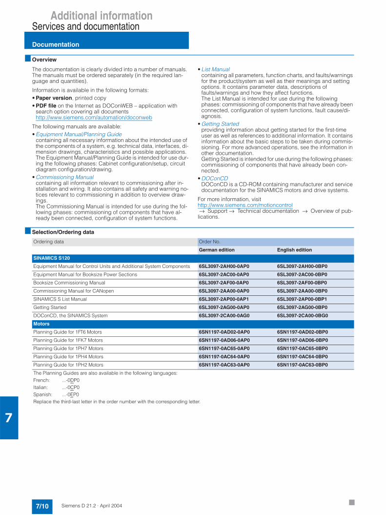
Additional informationServices and documentation
Documentation
7/10 Siemens D 21.2 · April 2004
7
Overview
The documentation is clearly divided into a number of manuals. The manuals must be ordered separately (in the required lan-guage and quantities).
Information is available in the following formats:• Paper version, printed copy• PDF file on the Internet as DOConWEB – application with
search option covering all documents http://www.siemens.com/automation/doconweb
The following manuals are available:• Equipment Manual/Planning Guide
containing all necessary information about the intended use of the components of a system, e.g. technical data, interfaces, di-mension drawings, characteristics and possible applications.The Equipment Manual/Planning Guide is intended for use dur-ing the following phases: Cabinet configuration/setup, circuit diagram configuration/drawing.
• Commissioning Manualcontaining all information relevant to commissioning after in-stallation and wiring. It also contains all safety and warning no-tices relevant to commissioning in addition to overview draw-ings.The Commissioning Manual is intended for use during the fol-lowing phases: commissioning of components that have al-ready been connected, configuration of system functions.
• List Manualcontaining all parameters, function charts, and faults/warnings for the product/system as well as their meanings and setting options. It contains parameter data, descriptions of faults/warnings and how they affect functions.The List Manual is intended for use during the following phases: commissioning of components that have already been connected, configuration of system functions, fault cause/di-agnosis.
• Getting Startedproviding information about getting started for the first-time user as well as references to additional information. It contains information about the basic steps to be taken during commis-sioning. For more advanced operations, see the information in other documentation.Getting Started is intended for use during the following phases: commissioning of components that have already been con-nected.
• DOConCDDOConCD is a CD-ROM containing manufacturer and service documentation for the SINAMICS motors and drive systems.
For more information, visithttp://www.siemens.com/motioncontrol→ Support → Technical documentation → Overview of pub-
lications.
Selection/Ordering data
Ordering data Order No.
German edition English edition
SINAMICS S120
Equipment Manual for Control Units and Additional System Components 6SL3097-2AH00-0AP0 6SL3097-2AH00-0BP0
Equipment Manual for Booksize Power Sections 6SL3097-2AC00-0AP0 6SL3097-2AC00-0BP0
Booksize Commissioning Manual 6SL3097-2AF00-0AP0 6SL3097-2AF00-0BP0
Commissioning Manual for CANopen 6SL3097-2AA00-0AP0 6SL3097-2AA00-0BP0
SINAMICS S List Manual 6SL3097-2AP00-0AP1 6SL3097-2AP00-0BP1
Getting Started 6SL3097-2AG00-0AP0 6SL3097-2AG00-0BP0
DOConCD, the SINAMICS System 6SL3097-2CA00-0AG0 6SL3097-2CA00-0BG0
Motors
Planning Guide for 1FT6 Motors 6SN1197-0AD02-0AP0 6SN1197-0AD02-0BP0
Planning Guide for 1FK7 Motors 6SN1197-0AD06-0AP0 6SN1197-0AD06-0BP0
Planning Guide for 1PH7 Motors 6SN1197-0AC65-0AP0 6SN1197-0AC65-0BP0
Planning Guide for 1PH4 Motors 6SN1197-0AC64-0AP0 6SN1197-0AC64-0BP0
Planning Guide for 1PH2 Motors 6SN1197-0AC63-0AP0 6SN1197-0AC63-0BP0
The Planning Guides are also available in the following languages:French: ...-0DP0Italian: ...-0CP0Spanish: ...-0EP0Replace the third-last letter in the order number with the corresponding letter.

Siemens D 21.2 · April 2004
8/2 Glossary
8/6 Siemens contact partnersworldwide
8/7 Information and orderingon the Internet and on CD-ROM
8/7 A&D on the WWW8/7 Product selection using the interac-
tive catalog8/7 Easy shopping with the A&D Mall
8/8 Subject index
8/9 Index of order numbers
8/10 Conditions of sale and delivery
8/10 Export regulations
Appendix

Additional informationAppendix
Glossary
8/2 Siemens D 21.2 · April 2004
8
Absolute encoder
Position encoder, which makes the position of the drive available immediately as an absolute value when it is connected to the power supply. On single-turn encoders, the detection range is one revolution and on multi-turn encoders a number of revolu-tions (typically e.g. 4096 revolutions).When using an absolute encoder as a position encoder, refer-ence point approach is not necessary following power-up, and the reference switch, which would otherwise be needed for this purpose (e.g. BERO) can be omitted. Rotary and linear absolutevalue encoders are available.
Example for an absolute encoder:1FK and 1FT6 motors can be supplied with built-in multi-turn ab-solute encoders with 2048 sinusoidal/cosinusoidal signals per revolution through 4096 revolutions (absolute) and → "EnDatprotocol".
Active Line Module
Regulated, self-commutating rectifier/regenerative unit (with IGBTs in rectifier/regenerative unit), which supplies the DC link voltage for the → "Motor Modules".
Asynchronous motor
The asynchronous motor is an AC motor, which runs at a speed "lagging behind" the synchronous speed. Asynchronous motors can be connected to the AC line both directly in a star or deltacircuit and via a frequency converter. When combined with a fre-quency converter, asynchronous motors form a "variable-speed drive system".Other designations currently in use: squirrel-cage motor, cage motor.
Booksize
Booksize configuration of the components of a drive suitable for mounting side-by-side. Designed primarily for multi-motor(→ "motors") operation.
Brake control
A software function, which defines when an available mechani-cal holding brake or service brake should be applied, either as part of a duty cycle for momentary standstill or in the event of a fault.
Braking Module
Electronic switch or chopper (brake chopper), which connects a → "braking resistor" with a specific pulse-no-pulse ratio to the DC link voltage in order to convert regenerative (braking) energy into heat energy and ultimately limit the DC link voltage to per-missible values. In the SINAMICS system, the Braking Module does not have a built-in braking resistor. The braking resistormust be installed outside the Braking Module.
Braking resistor
A resistor via which excess power in the DC link is dissipated. The resistor is connected to a → "Braking Module". It provides a means of discharging the resulting heat loss outside the control cabinet.
CAN bus
The acronym CAN stands for "Controller Area Network". CAN is a serial bus system in accordance with ISO 11898. CAN was originally developed for applications in automotive engineering(ISO 11519-1) but has established itself in other fields, e.g. in applications on textile and film machinery. A range of device pro-files was defined in → "CANopen" for CAN applications in indus-trial automation, in order to standardize communication at appli-cation level.
CANopen
CANopen is an expansion of the → "CAN bus" for standardized communication for various types of automation devices at appli-cation level.
Control Unit
Central control module, in which the closed-loop and open-loop control functions for one or more SINAMICS → "Line Modules" and/or → "Motor Modules" are implemented.
The following are examples of types of Control Units:• SINAMICS CU320 Control Unit• SIMOTION D435 Control Unit
Command data set
The parameters belonging to a motor data set define the config-uration of a → "motor". There are a number of data sets. Control commands can be used to toggle between them. This toggle function can be used to switch over all → "parameters", whichdefine the motor configuration, at once. A typical application is the operation of a number of motors on the same → "Motor Mod-ule". Example: The traveling motor and hoisting-gear motor on a hoist are linked to the same Motor Module and are connected to it alternately via contactors.
CompactFlash Card
Memory card for non-volatile storage of the drive software and corresponding parameters. The memory card can be plugged into the → "Control Unit" from the outside.
Direct measuring system
Position encoder, which is connected directly to the moving ma-chine part (→ "external encoder") as well as to the associated decoding electronics. On linear axes, linear position encoders can also be used for this purpose. In many cases, a direct mea-suring system must be used, because the → "motor encoder" forposition detection and control is not suitable. This might be due to excessive elasticities and backlash in the drive train.
Double Motor Module
Two motors can be connected to and operated with a Double Motor Module.
See → "Motor Module" → "Single Motor Module".

Additional informationAppendix
Glossary
8/3Siemens D 21.2 · April 2004
8
DRIVE-CLiQ
Abbreviation for Drive Component Link with IQ.
Communication system for connecting the various components of a SINAMICS drive system, e.g., → "Control Unit", → "LineModules", → "Motor Modules", → "motors" and speed/position encoders.In terms of hardware, DRIVE-CLiQ is based on Standard Indus-trial Ethernet with twisted-pair cables. The DRIVE-CLiQ cable provides the transmit and receive signals, as well as the +24 V power supply.
Drive group
A drive group comprises a → "Control Unit" and the → "MotorModules" and → "Line Modules" connected to it via → "DRIVE-CLiQ".
Droop
The speed controller is artificially "weakened" by droop, whereby a configurable (negative) percentage of the speed controlleroutput signal is applied to the speed controller input. In the event of high load torque, this will cause the speed to dip. Droop is ap-plied to take the edge off the response to load impulses and for certain types of load compensation control on drives, which are interconnected via a continuous web. The integral component or the summary output signal can be used as the speed output sig-nal. Droop can be activated and deactivated via a control com-mand.
Dynamic servo control (DSC)
Dynamic servo control (DSC) enables the position actual value to be evaluated during the fast speed control cycle directly onthe drive. The position setpoint is set in the position control cycle by the higher-level controller using the isochronous PROFIBUSwith PROFIdrive telegrams.DSC is able to use fine signal filtering and feedforward control tooptimize the dynamic response in the position control loop with-out overloading the bus bandwidth.DSC supports increased controller gain and therefore high rigid-ity, i.e. load-conditioned path deviations can be compensated quickly.
EnDat protocol
Serial transmission protocol for transmitting position/angular ac-tual values from an → "absolute encoder" to the drive control or position controller. The EnDat protocol can also be used to setthe parameters of and diagnose the encoder.
External encoder
Position encoder that is not built into or mounted on the → "motor", but is built on externally via a mechanical transmis-sion element or a mechanical intermediate element. The external encoder is used for direct position detection.
Fault buffer
Faults that have occurred are recorded in a fault buffer by thedrive. The fault buffer can be read out via parameters.
Field weakening
Field weakening describes the reducing of the magnetizing cur-rent of an electric motor in order that the speed can be increased further when the rated voltage is reached. Above the threshold speed for field weakening (the synchronous speed on asynchro-nous motors), the voltage is kept constant and the speed is con-trolled by varying the magnetizing current. The available torque drops in field weakening mode with the speed in accordance with the speed/torque characteristic.
Flying measurement
When a hardware signal is received, the current position actualvalue is stored and - e.g. via PROFIBUS - made available for fur-ther processing. The hardware signal can, for example, originate from a probe or a print-mark detection sensor (mechanical switch, BERO or optical sensor). The active edge of the hard-ware signal can be parameterized (rising, falling or both).
Flying restart
Following power-up, the "flying restart" function automatically switches a converter into any motor connected downstream. When the converter switches into the running motor, the current speed setpoint in the ramp-function generator is set to the cur-rent speed actual value. Ramp-up to the definitive speed set-point starts out at this value. The "flying restart" function can help to shorten the ramp-up procedure following power-up (if the load is still running down) (see → "automatic restart").
Incremental encoder
Incremental distance and speed encoder, which, unlike→ "absolute encoder", does not output a position actual value signal corresponding to the absolute distance, but incremental "differential distance or angular signals". Incremental encoders can be → "incremental encoders TTL/HTL", → "incremental en-coders sin/cos 1 Vpp" or → "resolvers".
Incremental encoder sin/cos 1 Vpp
This is a high-resolution optical sine/cosine encoder, which, for example, can be integrated into 1FK motors as a → "motor en-coder". The following signals are typically output:• Two 90-degree signals each with 2048 sinusoidal signals per
revolution as differential signals with an amplitude of 1 Vpp (A/B fine tracks).
• A reference signal (reset pulse) for each revolution as a differ-ential signal with an amplitude of 0.5 Vpp.
• On some types, also two 90-degree sinusoidal signals as dif-ferential signals with an amplitude of 1 Vpp (C/D track).The position/angular actual value is calculated by first evaluat-ing the zero crossovers of the fine tracks (approximate evalua-tion, e.g. a total of 4×2048 = 8192 zero crossovers per revolu-tion).Precise evaluation can then be carried out by means of analogdetection of the amplitude. The combination of approximate and precise evaluation makes possible resolutions of more than 1,000,000 increments per encoder revolution.Typical sin/cos encoders include: ERN1387, ERN1381.
Incremental encoders TTL/HTL
Incremental distance and speed encoder (→ "incremental en-coder"), which usually produces two 90-degree pulse trains (tracks) with square-wave output signals and generally also one reset pulse per revolution. The output signals are TTL-level (usu-ally +5 V RS422 differential signals; TTL = Transistor-TransistorLogic) or HTL-level (+15 or +24 V logic level; HTL = High Level Transistor Logic) signals.

Additional informationAppendix
Glossary
8/4 Siemens D 21.2 · April 2004
8
Kinetic buffering
Kinetic buffering is a software function, which can be used to bridge transient line failures (up to approx. 1 s or as long as the drive continues to turn). Kinetic buffering can usually only be used on drives that are primarily motor-driven. It requires a suffi-ciently large centrifugal mass, i.e. sufficient kinetic energy, on the part of the mechanical transmission element. During the line failure, the kinetic buffering switches the machine to no-load op-eration or light regeneration (in order to cover the minor losses from the motor and inverter). Once the line supply has been re-stored, the machine switches back to standard motor-driven op-eration. In order to use the kinetic buffering, the technological conditions must be in place to allow the motor to coast for the du-ration of the line failure. In some applications with multi-motordrives, the speed ratios between the individual drives have to be maintained during kinetic buffering, in order to prevent the web from tearing or damage. In such cases, kinetic buffering may only be activated on one of the drives (usually the main drive). The reduced speed setpoint values must then be fed into the overall setpoint cascade.
Line filters
Line filters are filters in the converter input that are designed to protect the network from harmonic loads and/or interference voltages created in the converter. Line filters can be passive or active filters, for the lower-frequency harmonics (line feedback) with 5, 7, 11, 13, etc. times the line frequency, and for high-fre-quency interference voltages 10 kHz and above (RFI suppres-sion filters). In relation to SINAMICS, line filters refer only to pas-sive radio interference suppression filters.
Line Module
A Line Module is a power component that generates the DC link voltage for one or more → "Motor Modules" from a 3-phase line voltage. In SINAMICS, there are two types of Line Module: → "Smart Line Modules" and → "Active Line Modules".
Line-side power components
Power components arranged between the line and converter unit (e.g. line reactors, line filters, line contactors, etc.).
Motor
For the electric motors that can be driven by SINAMICS, a basic distinction is made between rotary and linear motors with regard to their direction of motion, and between synchronous and asyn-chronous motors with regard to their electromagnetic operating principle. In SINAMICS, the motors are connected to a → "MotorModule". See → "synchronous motor" → "asynchronous motor" → "motor encoder" → "external encoder"
Motor encoder
An → "encoder", e.g. → "resolver", → "pulse encoder", → "incremental encoder TTL/HTL" or → "incremental encoder sin/cos 1 Vpp", built into or onto the motor. The encoder detects the motor speed and, in the case of synchronous motors, also the rotor position angle (of the commutation angle for the motor currents).
Motor Module
A Motor Module is a power unit (DC-AC inverter) that providesthe power supply for the connected motor(s). Power is supplied through the → "DC link" of the → "drive unit". A "Motor Module" must be connected with a → "Control Unit" housing the open-loop and closed-loop control functions for the Motor Module via → "DRIVE-CLiQ".There are → "Single Motor Modules" and → "Double Motor Mod-ules".
Motor potentiometer
This function is used to simulate an electromechanical motor po-tentiometer for setpoint input. The setpoint is adjusted via one control command for "higher" and one for "lower".
Optimized pulse patterns
Complex modulation procedure carried out by a converter gat-ing unit, whereby the voltage pulses are arranged so that theoutput current is as sinusoidal as possible. This is essential if high firing angles are to be maximized and torque ripple mini-mized.
PROFIBUS
Fieldbus standardized to IEC 61 158 Part 2 to 6.
PROFIdrive
PROFIBUS profile specified for speed and position-controlled drives by the PROFIBUS user organization (German: PNO). The latest version is the PROFIdrive V3 profile.
Pulse-edge modulation
Modulation method used by a converter gating unit, whereby the pulses "cut out" of the DC link voltage do not appear in a fixed time frame. The edges of the output voltage generated areformed by a small number of short pulses, while a wide pulse (around zero crossover) is generated in the middle of each half-wave. This provides the conditions for a high output voltage in the order of 100% of the supply voltage and consequently effi-cient motor performance.
Resolver
A very robust and cost effective (in mechanical and electrical terms) → "motor encoder", which does not require any built-in electronics and operates entirely in accordance with the electro-magnetic principle: One sinusoidal and one cosinusoidal signal is induced in each of two 90-degree tracks. The resolver sup-plies all the signals required for the speed-controlled operationof the converter and/or for position control. The number of sinu-soidal and cosinusoidal signals supplied per resolution is equal to the number of pole pairs of the resolver. On a two-pole re-solver, the decoding electronics can output an additional reset pulse for each encoder revolution, which enables the position in-formation to be uniquely assigned to a specific encoder resolu-tion. A 2-pole resolver can be used as a single-turn encoder. 2-pole resolvers can be used for motors with any number of pairs of poles. On multi-pole resolvers, the number of pole pairs of the motor and resolver are always the same. On multi-pole resolvers, the resolution is correspondingly higher than on 2-pole resolv-ers.
Additional informationAppendix
Glossary
8/5Siemens D 21.2 · April 2004
8
Safe brake control (SBC)
A → "Safety Integrated" function. On SINAMICS → "booksizemodules" the motor holding brake is controlled on a two-channel basis by one electronic switch in the 24 V channel and one in the ground channel. Both channels are monitored. The failure of one of the two channels is detected and reported. On booksize mod-ules, the brake line is integrated into the power cable.
Safe standstill (SH)
A → "Safety Integrated" function. The function is used in the event of a fault or in conjunction with a machine function to safely isolate the torque-generating power supply to the motor. This process takes place on a drive-specific and contactless basis.
Safety Integrated
Safety functions integrated into products for the effective protec-tion of personnel and machinery in accordance with EC Machin-ery Directive 98/37/EG.
The integrated safety functions provide a simple and cost-effec-tive means of meeting the requirements of Safety Category 3 to EN 954-1.
The Safety Integrated functions are:• → "Safe brake control" (SBC)• → "Safe standstill" (SH)
SBC and SH are implemented autonomously in the drive.
Sensor Module
Hardware module for evaluating speed/position encoder signals and providing detected actual values as numerical values on a → DRIVE-CLiQ socket.
SMCxx = Sensor Module Cabinet-mounted = Sensor Module for snap-on mounting in the control cabinet.
Single Motor Module
A Single Motor Module is a → "Motor Module" to which just one motor can be connected and operated. See → "Double Motor Module".
SIZER
SIZER is a tool for configuring the SINAMICS and MICROMAS-TER drive systems. SIZER assists with the correct technical specifications for the drive systems and selection of the drivecomponents required for the system.
Smart Line Modules
Non-regulated rectifier/regenerative unit with a diode bridge for the infeed and stall-protected, line-commutated feedback viaIGBTs. Smart Line Modules provide the DC link voltage for the→ "Motor Modules".
STARTER
STARTER assists with the startup and parameterization of drive units. This tool can also be used to execute the diagnostic func-tions required during servicing (e.g. PROFIBUS diagnostics,function generator, trace).
Suppression band
A suppression band is an illegal range of the speed or frequency setpoint. An upper and a lower limit parameter can be set for the suppression band. If an external or internal setpoint source sets a signal value within the suppression band, it is overwritten with one of the suppression band limits. This provides a means of suppressing undesirable sympathetic oscillations, whereby speeds which may induce such oscillations are suppressed.
Synchronous servo motor
Synchronous motors run at the same frequency with which they are operated: They do not have a slip (like → "asynchronous mo-tors"). Synchronous motors are built in different ways. They re-quire different feedforward and feedback control concepts de-pending on their design to ensure that they can be operated with converters. A distinction is made between permanent-field and separate-field synchronous motors, with/without a damping cage, and with/without a position encoder.
Terminal Board
Terminal extension module for plugging into a → "Control Unit". In SINAMICS, for example, Terminal Board 30 (TB30) is available with analog and digital I/O terminals.
Terminal Module
Terminal extension module for snapping onto the installation rail, for installation in the control cabinet. In SINAMICS, for example, Terminal Module 31 (TM31) is available with analog and digital I/O terminals.
Travel to fixed stop
This function can be used to move a motor to a fixed stop at a specified torque without a fault being signaled. When the stop is reached, the torque specified via parameters is built up and re-mains applied.

Additional informationAppendix
Siemens contact partners worldwide
8/6 Siemens D 21.2 · April 2004
8
At
www.siemens.com/automation/partner
you can find details of Siemens contact partners worldwide re-sponsible for particular technologies.
You can obtain in most cases a contact partner for• Technical Support,• Spare parts/repairs,• Service,• Training,• Sales or• Consultation/engineering.
You start by selecting a• Country,• Product or• Sector.
By further specifying the remaining criteria you will find exactly the right contact partner with his/her respective expertise.
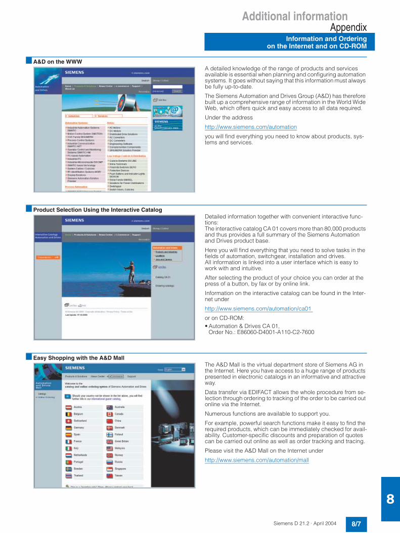
Additional informationAppendix
Information and Orderingon the Internet and on CD-ROM
8/7Siemens D 21.2 · April 2004
8
A&D on the WWWA detailed knowledge of the range of products and services available is essential when planning and configuring automation systems. It goes without saying that this information must always be fully up-to-date.
The Siemens Automation and Drives Group (A&D) has therefore built up a comprehensive range of information in the World Wide Web, which offers quick and easy access to all data required.
Under the address
http://www.siemens.com/automation
you will find everything you need to know about products, sys-tems and services.
Product Selection Using the Interactive CatalogDetailed information together with convenient interactive func-tions:The interactive catalog CA 01 covers more than 80,000 products and thus provides a full summary of the Siemens Automation and Drives product base.
Here you will find everything that you need to solve tasks in the fields of automation, switchgear, installation and drives. All information is linked into a user interface which is easy to work with and intuitive.
After selecting the product of your choice you can order at the press of a button, by fax or by online link.
Information on the interactive catalog can be found in the Inter-net under
http://www.siemens.com/automation/ca01
or on CD-ROM: • Automation & Drives CA 01,
Order No.: E86060-D4001-A110-C2-7600
Easy Shopping with the A&D Mall The A&D Mall is the virtual department store of Siemens AG in the Internet. Here you have access to a huge range of products presented in electronic catalogs in an informative and attractive way.
Data transfer via EDIFACT allows the whole procedure from se-lection through ordering to tracking of the order to be carried out online via the Internet.
Numerous functions are available to support you.
For example, powerful search functions make it easy to find the required products, which can be immediately checked for avail-ability. Customer-specific discounts and preparation of quotes can be carried out online as well as order tracking and tracing.
Please visit the A&D Mall on the Internet under
http://www.siemens.com/automation/mall

Additional informationAppendix
8/8 Siemens D 21.2 · April 2004
8
Subject indexPart/Page
AAC motors 3Active Line Modules 2/13Adapter set 2/5Applications 7/2Asynchronous motors 3/32
BBraking Module 2/24Braking resistors 2/26Built-in motors 3/57
CCables 5Capacitor Module 2/27CBC10 Communication Board 2/34CompactFlash Card 2/33Components 2Components, overview 1/10Configuration example 6/18Connection system 5Control Supply Module 2/28CU320 Control Unit 2/30
DDC link adapter 2/17, 2/21, 2/29DC link components 2/24 to 2/29Degrees of protection for motors 3/68Derating characteristics 2/4Dimensioning 6/6Documentation 7/10Double Motor Modules 2/21DRIVE-CLiQ 5Drive ES 6/4Drive ES engineering system 6/4
EElectronic rating plate 1/9Encoders 4Encoder system connection 2/39 to 2/42
GGear units 3/61 to 3/67Glossary 8/2
IIntroduction to SINAMICS 1/6Introduction to SINAMICS S120 1/8
LLength codes for cables 5/12Line filters 2/5Line Modules 2/10 to 2/15Line reactors 2/7Line-side power components 2/5 to 2/9Liquid cooling 3/60
Part/PageMMeasuring systems 4Modular system 1/8MOTION-CONNECT 5Motors 3Motor Modules 2/16 to 2/23
NNotes about configuration and planning 6
OOverload capability 2/3
PPlanetary gears 3/61 to 3/65Power cables 5/5 to 5/7
SSensor Modules SMC.. 2/40 to 2/42Services 7Service & Support 7/9Servo control drive system 1/8Signal cables 5/8 to 5/11SINAMICS, introduction 1/6SINAMICS system data 2/2Single Motor Modules 2/16SITRAIN 7/2SIZER 6/2SIZER configuration tool 6/2Smart Line Modules 2/10STARTER 6/3STARTER commissioning software 6/3STARTER drive/commissioning software 6/3Synchronous motors 3/2
TTB30 Terminal Board 2/35The planning process 6/5TM31 Terminal Module 2/37Totally Integrated Automation 1/4, 1/6Training 7/2Training case 7/6 to 7/8Two-speed gearbox 3/66 and 3/67Types of construction for motors 3/68

Additional informationAppendix
8/9Siemens D 21.2 · April 2004
8
Index of order numbersPage
1FK7 3/2, 3/27 to 3/311FT6 3/2 to 3/25
1PH2 3/33, 3/57 to 3/591PH4 3/32, 3/48 to 3/511PH7 3/32 to 3/471PM4 3/33, 3/52, 3/54 to 3/561PM6 3/33, 3/53 to 3/56
3KA5 2/93KL5 2/93KX3552-3EA01 2/9
3LD2 2/93LD9 2/9
3NA3 2/93NP4 2/93NP5 2/9
3RT10 2/93RV10 2/9
3TX7004-1LB00 2/9
3VF 2/9
5SB411 2/95SC211 2/95SE2335 2/9
6AG1064-1AA0 7/6
6ES7972-0B 2/32
6FC9341-2A 2/34
6FX2001-2 4/56FX2001-4 4/56FX2001-5 5/76FX2001-6 4/96FX2001-7 4/86FX2002-1D 5/106FX2003-0CE1 4/86FX2003-1CF1 4/5, 4/76FX2003-7 5/7, 5/11
6FX5002 5/6, 5/7, 5/10, 5/116FX8002 5/6, 5/7, 5/10, 5/11
6SL3000-0CE 2/7, 2/96SL3000-0DE 2/7, 2/96SL3000-0FE 2/5, 2/96SL3000-0GE 2/5, 2/9
6SL3040-0MA00-0AA1 2/32
Page
6SL3054-0AA0 2/33
6SL3055-0AA00-2CA0 2/346SL3055-0AA00-2TA0 2/356SL3055-0AA00-3AA0 2/376SL3055-0AA00-5AA0 2/406SL3055-0AA00-5BA1 2/416SL3055-0AA00-5CA0 2/42
6SL3060-1FE21 2/56SL3060-4A 5/106SL3064-1BB00-0AA0 2/32
6SL3070-0AA00-0AG0 6/26SL3072-0AA00-0AG0 6/36SL3074-0AA01-0AA0 2/33
6SL3097 7/10
6SL3100-1AE31-0AA0 2/246SL3100-1BE31-0AA0 2/266SL3100-1CE14-0AA0 2/276SL3100-1DE22-0AA0 2/28
6SL3120-1TE 2/166SL3120-2TE 2/216SL3130-6AE 2/106SL3130-7TE 2/13
6SL3162-1A 2/13, 2/17, 6SL3162-2A 2/17, 2/216SL3162-2B 2/17, 2/21, 2/29
6SL3166-3AB00-0AA0 2/10, 2/13, 2/17, 2/21, 2/24, 2/27, 2/28
6SN1111-0AA00 2/7, 2/96SN1113-1AA00-0DA0 2/266SN1162-0GA00 2/56SN1197-0AB10-0YP3 4/76SN1197-0AB30-0AP2 4/96SN1197-0AC 7/106SN1197-0AD 7/10
6SW1700 6/4
6SX7002 5/10
6ZB2470-0AE00 7/86ZB2470-0AG00 7/76ZB2470-0AH00 7/7
6ZB2480-0AA00 7/66ZB2480-0BA00 7/6
E86060 7/3
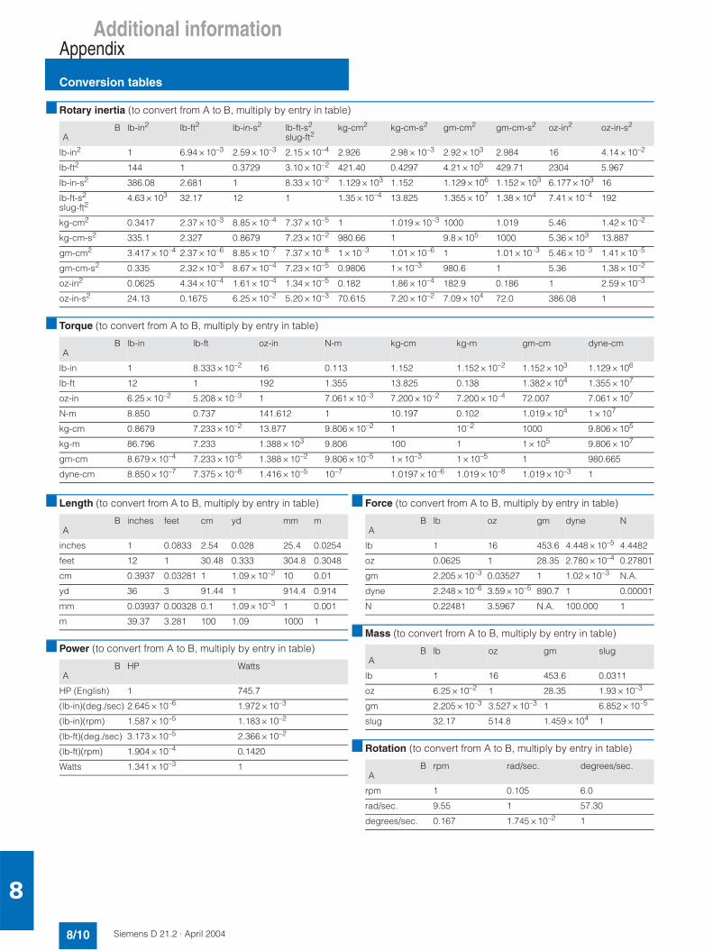
Additional informationAppendix
Conversion tables
8/10 Siemens D 21.2 · April 2004
8
Rotary inertia (to convert from A to B, multiply by entry in table)
Torque (to convert from A to B, multiply by entry in table)
Length (to convert from A to B, multiply by entry in table)
Power (to convert from A to B, multiply by entry in table)
Force (to convert from A to B, multiply by entry in table)
Mass (to convert from A to B, multiply by entry in table)
Rotation (to convert from A to B, multiply by entry in table)
BA
lb-in2 lb-ft2 lb-in-s2 lb-ft-s2
slug-ft2kg-cm2 kg-cm-s2 gm-cm2 gm-cm-s2 oz-in2 oz-in-s2
lb-in2 1 6.94 × 10⁻³ 2.59 × 10⁻³ 2.15 × 10⁻⁴ 2.926 2.98 × 10⁻³ 2.92 × 10³ 2.984 16 4.14 × 10⁻²
lb-ft2 144 1 0.3729 3.10 × 10⁻² 421.40 0.4297 4.21 × 10⁵ 429.71 2304 5.967
lb-in-s2 386.08 2.681 1 8.33 × 10⁻² 1.129 × 10³ 1.152 1.129 × 10⁶ 1.152 × 10³ 6.177 × 10³ 16
lb-ft-s2
slug-ft24.63 × 103 32.17 12 1 1.35 × 10⁻⁴ 13.825 1.355 × 10⁷ 1.38 × 10⁴ 7.41 × 10⁻⁴ 192
kg-cm2 0.3417 2.37 × 10⁻³ 8.85 × 10⁻⁴ 7.37 × 10⁻⁵ 1 1.019 × 10⁻³ 1000 1.019 5.46 1.42 × 10⁻²
kg-cm-s2 335.1 2.327 0.8679 7.23 × 10⁻² 980.66 1 9.8 × 10⁵ 1000 5.36 × 10³ 13.887
gm-cm2 3.417 × 10⁻⁴ 2.37 × 10⁻⁶ 8.85 × 10⁻⁷ 7.37 × 10⁻⁸ 1 × 10⁻³ 1.01 × 10⁻⁶ 1 1.01 × 10⁻³ 5.46 × 10⁻³ 1.41 × 10⁻⁵
gm-cm-s2 0.335 2.32 × 10⁻³ 8.67 × 10⁻⁴ 7.23 × 10⁻⁵ 0.9806 1 × 10⁻³ 980.6 1 5.36 1.38 × 10⁻²
oz-in2 0.0625 4.34 × 10⁻⁴ 1.61 × 10⁻⁴ 1.34 × 10⁻⁵ 0.182 1.86 × 10⁻⁴ 182.9 0.186 1 2.59 × 10⁻³
oz-in-s2 24.13 0.1675 6.25 × 10⁻² 5.20 × 10⁻³ 70.615 7.20 × 10⁻² 7.09 × 10⁴ 72.0 386.08 1
BA
lb-in lb-ft oz-in N-m kg-cm kg-m gm-cm dyne-cm
lb-in 1 8.333 × 10⁻² 16 0.113 1.152 1.152 × 10⁻² 1.152 × 10³ 1.129 × 10⁶
lb-ft 12 1 192 1.355 13.825 0.138 1.382 × 10⁴ 1.355 × 10⁷
oz-in 6.25 × 10⁻² 5.208 × 10⁻³ 1 7.061 × 10⁻³ 7.200 × 10⁻² 7.200 × 10⁻⁴ 72.007 7.061 × 10⁷
N-m 8.850 0.737 141.612 1 10.197 0.102 1.019 × 10⁴ 1 × 10⁷
kg-cm 0.8679 7.233 × 10⁻² 13.877 9.806 × 10⁻² 1 10–2 1000 9.806 × 10⁵
kg-m 86.796 7.233 1.388 × 10³ 9.806 100 1 1 × 10⁵ 9.806 × 10⁷
gm-cm 8.679 × 10⁻⁴ 7.233 × 10⁻⁵ 1.388 × 10⁻² 9.806 × 10⁻⁵ 1 × 10⁻³ 1 × 10⁻⁵ 1 980.665
dyne-cm 8.850 × 10⁻⁷ 7.375 × 10⁻⁸ 1.416 × 10⁻⁵ 10–7 1.0197 × 10⁻⁶ 1.019 × 10⁻⁸ 1.019 × 10⁻³ 1
BA
inches feet cm yd mm m
inches 1 0.0833 2.54 0.028 25.4 0.0254
feet 12 1 30.48 0.333 304.8 0.3048
cm 0.3937 0.03281 1 1.09 × 10⁻² 10 0.01
yd 36 3 91.44 1 914.4 0.914
mm 0.03937 0.00328 0.1 1.09 × 10⁻³ 1 0.001
m 39.37 3.281 100 1.09 1000 1
BA
HP Watts
HP (English) 1 745.7
(lb-in)(deg./sec) 2.645 × 10⁻⁶ 1.972 × 10⁻³
(lb-in)(rpm) 1.587 × 10⁻⁵ 1.183 × 10⁻²
(lb-ft)(deg./sec) 3.173 × 10⁻⁵ 2.366 × 10⁻²
(lb-ft)(rpm) 1.904 × 10⁻⁴ 0.1420
Watts 1.341 × 10⁻³ 1
BA
lb oz gm dyne N
lb 1 16 453.6 4.448 × 10⁻⁵ 4.4482
oz 0.0625 1 28.35 2.780 × 10⁻⁴ 0.27801
gm 2.205 × 10⁻³ 0.03527 1 1.02 × 10⁻³ N.A.
dyne 2.248 × 10⁻⁶ 3.59 × 10⁻⁵ 890.7 1 0.00001
N 0.22481 3.5967 N.A. 100.000 1
BA
lb oz gm slug
lb 1 16 453.6 0.0311
oz 6.25 × 10⁻² 1 28.35 1.93 × 10⁻³
gm 2.205 × 10⁻³ 3.527 × 10⁻³ 1 6.852 × 10⁻⁵
slug 32.17 514.8 1.459 × 10⁴ 1
BA
rpm rad/sec. degrees/sec.
rpm 1 0.105 6.0
rad/sec. 9.55 1 57.30
degrees/sec. 0.167 1.745 × 10⁻² 1

Additional informationAppendix
Conversion tables
8/11Siemens D 21.2 · April 2004
8
Temperature conversion
Mechanism Efficiencies
Friction Coefficients
Material Densities
Wire Gauges 1)
°F °C °C °F
0 –17.8 –10 14
32 0 0 32
50 10 10 50
70 21.1 20 68
90 32.2 30 86
98.4 37 37 98.4
212 100 100 212
subtract 32 and multiply by 5/9 multiply by 9/5 and add 32
Acme-screw with brass nut ~0.35–0.65
Acme-screw with plastic nut ~0.50–0.85
Ball-screw ~0.85–0.95
Chain and Sprocket ~0.95–0.98
Preloaded Ball-screw ~0.75–0.85
Spur or Bevel-gears ~0.90
Timing Belts ~0.96–0.98
Worm Gears ~0.45–0.85
Helical Gear (1 reduction) ~0.92
Materials µ
Steel on Steel (greased) ~0.15
Plastic on Steel ~0.15–0.25
Copper on Steel ~0.30
Brass on Steel ~0.35
Aluminium on Steel ~0.45
Steel on Steel ~0.58
Mechanism µ
Ball Bushings <0.001
Linear Bearings <0.001
Dove-tail slides ~0.2++
Gibb Ways ~0.5++
Material lb-in3 gm-cm3
Aluminium 0.096 2.66
Brass 0.299 8.30
Bronze 0.295 8.17
Copper 0.322 8.91
Hard Wood 0.029 0.80
Soft Wood 0.018 0.48
Plastic 0.040 1.11
Glass 0.079–0.090 2.2–2.5
Titanium 0.163 4.51
Paper 0.025–0.043 0.7–1.2
Polyvinyl chloride 0.047–0.050 1.3–1.4
Rubber 0.033–0.036 0.92–0.99
Silicone rubber, without filler 0.043 1.2
Cast iron, grey 0.274 7.6
Steel 0.280 7.75
Cross-Sectionmm2
Standard WireGauge (SWG)
American WireGauge (AWG)
0.2 25 24
0.3 23 22
0.5 21 20
0.75 20 19
1.0 19 18
1.5 17 16
2.5 15 13
4 13 11
6 12 9
10 9 7
16 7 6
25 5 3
35 3 2
50 0 1/0
70 000 2/0
95 00000 3/0
120 0000000 4/0
150 – 6/0
185 – 7/0
1) Table shows approximate SWG/AWG sizes nearest to standard metricsizes; the cross-sections do not match exactly.

Additional informationAppendix
Notes
8/12 Siemens D 21.2 · April 2004
8

Additional informationAppendix
Notes
8/13Siemens D 21.2 · April 2004
8

Additional informationAppendix
8/14 Siemens D 21.2 · April 2004
8
Terms and Conditions of Sale and Delivery
By using this catalog you can acquire hardware and software products described therein from the Siemens AG subject to the following terms. Please note! The scope, the quality and the con-ditions for supplies and services, including software products, by any Siemens entity having a registered office outside of Ger-many, shall be subject exclusively to the General Terms and Conditions of the respective Siemens entity.
for customers with a seat or registered office in the Federal Republic of GermanyThe General Terms of Payment as well as the General Conditionsfor the Supply of Products and Services of the Electrical andElectronics Industry shall apply.For software products, the General License Conditions for Soft-ware Products for Automation and Drives for Customers withSeat or registered Office in Germany shall apply.
for customers with a seat or registered office outside of the Federal Republic of GermanyThe General Terms of Payment as well as the General Conditionsfor Supplies of Siemens, Automation and Drives for Customerswith a Seat or registered Office outside of Germany shall apply.For software products, the General License Conditions for Soft-ware Products for Automation and Drives for Customers withSeat or registered Office outside of Germany shall apply.
GeneralThe prices are in € (Euro) ex works, exclusive packaging.The sales tax (value added tax) is not included in the prices. It shall be debited separately at the respective rate according to the applicable legal regulations.In addition to the prices of products which include silver and/or copper, surcharges may be calculated if the respective limits of the notes are exceeded.Prices are subject to change without prior notice. We will debit the prices valid at the time of delivery. The dimensions are in mm. Illustrations are not binding.Insofar as there are no remarks on the corresponding pages, - especially with regard to data, dimensions and weights given - these are subject to change without prior notice.
Comprehensive Terms and Conditions of Sale and Delivery are available free of charge from your local Siemens business office under the following Order Nos.:• 6ZB5310-0KR30-0BA0
(for customers based in the Federal Republic of Germany)• 6ZB5310-0KS53-0BA0
(for customers based outside of the Federal Republic of Germany)
or download them from the Internet:www.siemens.com/automation/mall(Germany: A&D Mall Online-Help System)
Export regulations
The products listed in this catalog / price list may be subject to European / German and/or US export regulations.Therefore, any export requiring a license is subject to approval by the competent authorities.According to current provisions, the following export regulations must be observed with respect to the products featured in this catalog / price list:
Even without a label or with an "AL: N" or "ECCN: N", authoriza-tion may be required due to the final destination and purpose for which the goods are to be used.The deciding factors are the AL or ECCN export authorization indicated on order confirmations, delivery notes and invoices.Errors excepted and subject to change without prior notice.
Responsible for
Technical content:Siemens AG, A&D MC
General editing:Siemens AG, A&D PT 5, Erlangen,Germany
Siemens AGAutomation & DrivesMotion Control SystemsPostfach 326991050 ERLANGEN, FEDERAL REPUBLIC OF GERMANY
Order No.: E86060-K5521-A121-A1-7600Printed in the Federal Republic of GermanyKG K 0804 8.0 BD 188 En/P422001
AL Number of the German Export List.Products marked other than "N" require an export license.In the case of software products, the export des-ignations of the relevant data medium must also be generally adhered to.Goods labeled with an "AL not equal to N" are subject to a European or German export authori-zation when being exported out of the EU.
ECCN Export Control Classification Number.Products marked other than “N“ are subject to a reexport license to specific countries.In the case of software products, the exportdesignations of the relevant data medium must also be generally adhered to.Goods labeled with an "ECCN not equal to N" are subject to a US re-export authorization.
Catalogs of theAutomation and Drives Group (A&D)
Please send any request to your Siemens representativeAddresses can be found at http://www.siemens.com/automation/partner
A&D/3U/En 17.06.04
Automation and Drives CatalogInteractive catalog on CD-ROM
• The Offline Mall of Automation and Drives CA 01
Automation Systems for Machine ToolsSINUMERIK & SIMODRIVE NC 60
Drive SystemsVariable-Speed Drives
SINAMICS G130 Drive Converter Chassis UnitsSINAMICS G150 Drive Converter Cabinet Units
D 11
SINAMICS G110 Inverter Chassis Units D 11.1
SINAMICS S120 Servo Control Drive SystemSINAMICS S150 Drive Converter Cabinet Units
D 21.2D 21.3
DC Motors DA 12
DC Drives Preferred Series up to 500 kW DA 12.1
DC Drives Preferred Series 215 kW to 1500 kW DA 12.2
SIMOREG DC MASTER 6RA70 Digital Chassis Converters
DA 21.1
SIMOREG K 6RA22 Analog Chassis Converters DA 21.2
SIMOREG DC MASTER 6RM70 Digital Converter Cabinet Units
DA 22
SIMOVERT PM Modular Converter Systems DA 45
SIEMOSYN Motors DA 48
MICROMASTER 410/420/430/440 Inverters DA 51.2
MICROMASTER 411/COMBIMASTER 411 DA 51.3
SIMOVERT MV Medium-Voltage Drives DA 63
SIMOVERT MASTERDRIVES Vector Control DA 65.10
SIMOVERT MASTERDRIVES Motion Control DA 65.11
Synchronous and asynchronous servomotors for SIMOVERT MASTERDRIVES
DA 65.3
SIMODRIVE 611 universal and POSMO DA 65.4
Low-Voltage Three-Phase-Motors
Project Manual M 10
Squirrel-Cage Motors, Totally Enclosed, Fan-Cooled M 11
Automation Systems for Machine Tools SIMODRIVE NC 60
• Main Spindle Motors
• Feed Motors
• Converter Systems SIMODRIVE 611/POSMO
Drive and Control Components for Hoisting Equipment HE 1
Electrical Installation TechnologyPDF: ALPHA Small Distribution Boards and
Distribution BoardsET A1
PDF: ALPHA Side-by-Side Switchgear Cabinets ET A3
PDF: ALPHA FIX Terminal Blocks ET A5
PDF: BETA Modular Installation Devices ET B1
PDF: DELTA Switches and Outlets ET D1
PDF: GAMMA Building Management Systems ET G1
Factory Automation Sensors FS 10
Human Machine Interface Systems SIMATIC HMI ST 80
PDF: These catalogs are only available as pdf files.
Industrial Communication for Automation and Drives
CatalogIK PI
Low-Voltage Controls and DistributionLow-Voltage Switchgear – Controlgear for Industry LV 10
Power Distribution – Products and Systemsfor Low-Voltage Power Distribution
LV 30
SIVACON 8PS Busbar Trunking Systems CD, BD01, BD2 up to 1250 A
LV 70
SENTRON WL NS WL
Motion Control System SIMOTION PM 10
Process Instrumentation and AnalyticsField Instruments for Process AutomationMeasuring Instruments for Pressure, Differential Pressure, Flow, Level and Temperature, Positioners and Liquid Meters
FI 01
PDF: Indicators for panel mounting MP 12
SIREC Recorders and Accessories MP 20
SIPART, Controllers and Software MP 31
SIWAREX Weighing Systems WT 01
Continuous Weighing and Process Protection WT 02
Gas Analysis Equipment for the Process Industry PA 10
PDF: Process Analytics, Components for the System Integration
PA 11
SIPAN Liquid Analysis PA 20
SIMATIC Industrial Automation SystemsSIMATIC PCS Process Control System ST 45
PDF: SIMATIC S5/505 Automation Systems ST 50
Components for Totally Integrated Automation and Micro Automation
ST 70
SIMATIC PCS 7 Process Control System ST PCS 7
PDF: Add-ons for the SIMATIC PCS 7Process Control System
ST PCS 7.A
SIMATIC Control Systems ST DA
SIPOS Electric ActuatorsElectric Rotary, Linear and Part-turn Actuators MP 35
Electric Rotary Actuators for Nuclear Plants MP 35.1/.2
Systems EngineeringPower supplies SITOP power KT 10.1
System cabling SIMATIC TOP connect KT 10.2
Industrial Microcomputers SICOMP KT 51
System SolutionsApplications and Products for Industry are part of the interactive catalog CA 01
TELEPERM M Process Control SystemAS 235, AS 235H and AS 235K automation systems PLT 111
PDF: AS 488/TM automation systems PLT 112
Operating and monitoring with WinCC/TM PLT 123
CS 275 bus system PLT 130
6$<*4::(=//(((;:
%! !!!# !! !$# , !, !$ #!#> $ %!/"?
&!0:@@/*+5-*A**+5+*&9756A-*+B
$$C(
The enclosed CD-ROM for catalog D 21.2 · April 2004 contains:• Information on planning/configuration based on the technical documentation;
further technical documentation can be found at:http://www.siemens.com/automation/doconweb
• Dimension drawings of our motors (PDF/DXF format)• Catalog D 21.2, in electronic form (PDF format)
Hardware and software requirements• Intel Pentium 333 MHz or higher• At least 128 MB RAM• Screen resolution 1024 x 768 pixels• 4x CD-ROM drive• Windows 9x/NT 4.x/2000/XP• Acrobat Reader• MS Internet Explorer version 5.5
StartInsert the CD into the CD-ROM drive. The program starts automatically. If the AutoRun function is not activated in your system, please start the "start.hta" file fromthe CD-ROM in Windows Explorer.
NoteNo programs have to be installed to view the information on this CD-ROM.The use of dimensions drawings in DXF format is an exception.
HotlinePlease send any queries and suggestions to: motioncontrol.docu@erlf. siemens.de
CD-ROM for catalog D 21.2