Cyprus National Annex EN 1992-2 · 2019-06-19 · following clauses in CYS EN 1992-2:2005 (see...
13
NATIONAL ANNEX NATIONAL ANNEX TO CYS EN 1992-2:2005 (Including AC:2008) Eurocode 2: Design of concrete structures Part 2: Concrete bridges NA to CYS EN 1992-2:2005 (Including AC:2008)
Transcript of Cyprus National Annex EN 1992-2 · 2019-06-19 · following clauses in CYS EN 1992-2:2005 (see...

NATIONAL ANNEX
NATIONAL ANNEXTOCYS EN 1992-2:2005 (Including AC:2008)
Eurocode 2: Design of concrete structures
Part 2: Concrete bridges
NA to CYS EN 1992-2:2005(Including AC:2008)
NATIONAL ANNEX
TO
CYS EN 1992-2:2005+AC:2008
Eurocode 2: Design of concrete structures
Part 2: Concrete bridges
This National Annex has been approved by the Board of Directors of the
Cyprus Organisation for Standardisation (CYS) on 14.06.2019.
Copyright
Right to reproduce and distribute belongs to the Cyprus Organisation for
Standardisation.
No part of this publication may be reproduced or utilized in any form or by any
means, electronic or mechanical, including photocopying, without permission in
writing from Cyprus Organisation for Standardisation.
If you have any questions about standards copyright, please contact Centre of
Information and Customer Service at the Cyprus Organisation for Standardisation
phone: +357 22 411413/4 email: [email protected]

National Annex to CYS EN 1992-2:2005+AC:2008 Eurocode 2: Design of Concrete Structures Part 2: Concrete Bridges
CYS TC 18 Page 2 of 10
INTRODUCTION This National Annex has been prepared by the CYS TC 18 National Standardisation Technical Committee of Cyprus organisation for standardisation
NA 1 SCOPE This National Annex is to be used together with CYS EN 1992-2:2005+AC:2008. Any reference in the rest of this text to CYS EN 1992-2:2005 means the above document.
This National Annex gives:
(a) Nationally determined parameters for the following clauses of CYS EN 1992-2:2005+AC:2008 where National choice is allowed (see Section NA 2)
3.1.2 (102) P 3.1.6 (101) P 3.1.6 (102) P 3.2.4 (101) P 4.2 (105) 4.2 (106) 4.4.1.2 (109) 5.1.3 (101)P 5.2 (105) 5.3.2.2 (104) 5.5 (104) 5.7 (105) 6.1 (109) 6.1 (110) 6.2.2 (101) 6.2.3 (103) 6.2.3 (107) 6.2.3 (109) 6.8.1 (102) 6.8.7 (101) 7.2 (102) 7.3.1 (105) 7.3.3 (101) 7.3.4 (101) 8.9.1 (101) 8.10.4 (105) 8.10.4 (107) 9.1 (103) 9.2.2 (101) 9.5.3 (101) 9.7 (102) 9.8.1 (103) 11.9 (101) 113.2 (102) 113.3.2 (103)

National Annex to CYS EN 1992-2:2005+AC:2008 Eurocode 2: Design of Concrete Structures Part 2: Concrete Bridges
CYS TC 18 Page 3 of 10
(b) Decisions on the use of the Informative Annexes A, B, D, F, G, H, J, KK, LL, NN, OO,and PP (see Section NA 3)
(c) References to non-contradictory complementary information to assist the user to applyCYS EN 1992-2:2005. In this National Annex such information is provided for thefollowing clauses in CYS EN 1992-2:2005 (see Section NA 4)
NA 2 NATIONALLY DETERMINED PARAMETERS
NA 2.1 Clause 3.1.2 (102)P Materials - Concrete - Strength The values of Cmin and Cmax are specified as C30/37 and C70/85 respectively.
NA 2.2 Clause 3.1.6 (101)P Design compressive and tensile strengths
The value of cc is specified as 0,85.
NA 2.3 Clause 3.1.6 (102)P Design compressive and tensile strengths
The value of ct is specified as 1,0.
NA 2.4 Clause 3.2.4 (101)P Reinforcing Steel - Ductility characteristics The classes of reinforcement to be used in bridges are Class B and Class C.
NA 2.5 Clause 4.2 (105) Durability and cover Reinforcement - Environmental conditions
The exposure class for surfaces protected by waterproofing is XC3.
NA 2.6 Clause 4.2 (106) Environmental conditions The value for distance x is set to 6m and the value for distance y is set to 6m.
The exposure classes for surfaces directly affected by de-icing salts are XD3 and XF2 or XF4, as appropriate, with covers given in Tables 4.4(CYS) and 4.5(CYS) for XD classes (CYS EN 1992-1-1:2004).
NA 2.7 Clause 4.4.1.2 (109) Concrete cover - Minimum cover, cmin Provided that the following conditions are met, the cover needs only satisfy the requirements for bond (see 4.4.1.2 (3) of CYS EN 1992-1-1:2004): - The existing concrete surface has not been subject to an outdoor environment for more
than 28 days.- The existing concrete surface is rough.- The strength class of the existing concrete is at least C25/30.
NA 2.8 Clause 5.1.3 (101)P Structural Analysis - Load cases and combinations No simplifications to the load arrangements for use are given in this National Annex.
NA 2.9 Clause 5.2(105) Geometric imperfections The value of 0 is specified as 1/200.
NA 2.10 Clause 5.3.2.2 (104) Geometric data - Effective span of beams and slabs
The value of t is specified as the breadth of the bearing.

National Annex to CYS EN 1992-2:2005+AC:2008 Eurocode 2: Design of Concrete Structures Part 2: Concrete Bridges
CYS TC 18 Page 4 of 10
NA 2.11 Clause 5.5(104) Linear elastic analysis with limited redistribution The values of k1, k2 , k3, k4 and k5 are specified as follows:
k1 = 0,44
k2 = 1,25(0,6+0,0014/cu2)
k3 = 0,54
k4 = 1,25(0,6+0,0014/cu2)
k5 = 0,85
NA 2.12 Clause 5.7 (105) Non-linear analysis The details of acceptable methods for non-linear analysis and safety format to be used are as follows:
When using non-linear analysis the following assumptions shall be made:
For reinforcing steel, the stress-strain diagram to be used shall be based on Figure 3.8,curve A (CYS EN 1992-1-1:2004). In this diagram, fyk and kfyk shall be replaced by 1,1fyk
and 1,1kfyk
For prestressing steel, the idealised stress-strain diagram given in 3.3.6 (Figure 3.10,curve A, (CYS EN 1992-1-1:2004)) shall be used. In this diagram fpk shall be replacedwith 1.1 fpk
For concrete, the stress-strain diagram shall be based on expression (3.14) in 3.1.5. (CYSEN 1992-1-1:2004). In this expression, and in the k-value, fcm shall be replaced by γcf.fck
with γcf = 1,1.γS /γC.
The following design format shall be used:
The resistance shall be evaluated for different levels of appropriate actions which shall beincreased from their serviceability values by incremental steps, such that the value ofG.Gk and Q.Qk are reached in the same step. The incrementing process shall be continueduntil one region of the structure attains the ultimate strength, evaluated taking account ofαcc, or there is global failure of the structure. The corresponding load is referred to as qud.
Apply an overall safety factor γΟ and obtain the corresponding strength
O
udqR
,
One of the following inequalities shall be satisfied:
O
udQGRd
qRQGE
(5.102.aCYS)
or
ORd
udQG
qRQGE
.(5.102.bCYS)
(i.e.)
'O
udqR
or
National Annex to CYS EN 1992-2:2005+AC:2008 Eurocode 2: Design of Concrete Structures Part 2: Concrete Bridges
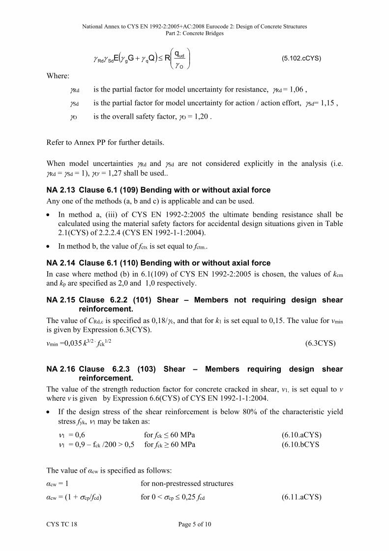
CYS TC 18 Page 5 of 10
O
udqgSdRd
qRQGE
(5.102.cCYS)
Where:
Rd is the partial factor for model uncertainty for resistance, Rd = 1,06 ,
Sd is the partial factor for model uncertainty for action / action effort, Sd= 1,15 ,
O is the overall safety factor, O = 1,20 .
Refer to Annex PP for further details.
When model uncertainties Rd and Sd are not considered explicitly in the analysis (i.e. Rd = Sd = 1), O' = 1,27 shall be used..
NA 2.13 Clause 6.1 (109) Βending with or without axial force Any one of the methods (a, b and c) is applicable and can be used.
In method a, (iii) of CYS EN 1992-2:2005 the ultimate bending resistance shall becalculated using the material safety factors for accidental design situations given in Table2.1(CYS) of 2.2.2.4 (CYS EN 1992-1-1:2004).
In method b, the value of fctx is set equal to fctm..
NA 2.14 Clause 6.1 (110) Βending with or without axial force In case where method (b) in 6.1(109) of CYS EN 1992-2:2005 is chosen, the values of kcm and kp are specified as 2,0 and 1,0 respectively.
NA 2.15 Clause 6.2.2 (101) Shear – Members not requiring design shear reinforcement.
The value of CRd,c is specified as 0,18/c, and that for k1 is set equal to 0,15. The value for vmin is given by Expression 6.3(CYS).
vmin =0,035 k3/2 fck1/2 (6.3CYS)
NA 2.16 Clause 6.2.3 (103) Shear – Members requiring design shear reinforcement.
The value of the strength reduction factor for concrete cracked in shear, ν1, is set equal to ν where ν is given by Expression 6.6(CYS) of CYS EN 1992-1-1:2004.
If the design stress of the shear reinforcement is below 80% of the characteristic yieldstress fyk, 1 may be taken as:
1 = 0,6 for fck ≤ 60 MPa (6.10.aCYS) 1 = 0,9 – fck /200 > 0,5 for fck ≥ 60 MPa (6.10.bCYS
The value of αcw is specified as follows:
αcw = 1 for non-prestressed structures
αcw = (1 + cp/fcd) for 0 < cp 0,25 fcd (6.11.aCYS)

National Annex to CYS EN 1992-2:2005+AC:2008 Eurocode 2: Design of Concrete Structures Part 2: Concrete Bridges
CYS TC 18 Page 6 of 10
αcw = 1,25 for 0,25 fcd < cp 0,5 fcd (6.11.bCYS)
αcw = 2,5 (1 - cp/fcd) for 0,5 fcd < cp < 1,0 fcd (6.11.cCYS)
where:
cp is the mean compressive stress, measured positive, in the concrete due to the design axial force. This shall be obtained by averaging it over the concrete section taking account of the reinforcement. The value of cp need not be calculated at a distance less than 0.5d cot from the edge of the support.
NA 2.17 Clause 6.2.3 (107) Shear – Members requiring design shear reinforcement.
No additional guidance on the superposition of different truss models is given in this National Annex.
The guidance given in this National Annex is as follows:
In the case of bonded prestressing, located within the tensile chord, the resisting effect ofprestressing may be taken into account for carrying the total longitudinal tensile force. Inthe case of inclined bonded prestressing tendons in combination with other longitudinalreinforcement/tendons the shear strength may be evaluated, by a simplification,superimposing two different truss models with different geometry (Figure. 6.102CYS); aweighted mean value between 1 and 2 may be used for concrete stress field verificationwith Expression (6.9) of CYS EN 1992-2:2005.
Figure 6.102(CYS): Superimposed resisting model for shear
NA 2.18 Clause 6.2.3 (109) Shear – Members requiring design shear reinforcement.
The absolute minimum value for hred is specified as 0,5h.
NA 2.19 Clause 6.8.1 (102) Fatigue – Verification conditions No additional rules for fatigue verification are defined in this National Annex.
1
2
National Annex to CYS EN 1992-2:2005+AC:2008 Eurocode 2: Design of Concrete Structures Part 2: Concrete Bridges
CYS TC 18 Page 7 of 10
NA 2.20 Clause 6.8.7 (101) Fatigue – Verification of concrete under compression or shear
The value of k1 is specified as 0,85.
NA 2.21 7.2 Stresses The value of k1 is specified as 0,6 and the maximum increase in the stress limit above k1fck in the presence of confinement is set to 10%.
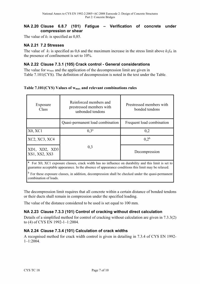
NA 2.22 Clause 7.3.1 (105) Crack control - General considerations The value for wmax and the application of the decompression limit are given in Table 7.101(CYS). The definition of decompression is noted in the text under the Table.
Table 7.101(CYS) Values of wmax and relevant combinations rules
Exposure Class
Reinforced members and prestressed members with
unbonded tendons
Prestressed members with bonded tendons
Quasi-permanent load combination Frequent load combination
X0, XC1 0,3a 0,2
XC2, XC3, XC4
0,3
0,2b
XD1, XD2, XD3 XS1, XS2, XS3
Decompression
a For X0, XC1 exposure classes, crack width has no influence on durability and this limit is set to guarantee acceptable appearance. In the absence of appearance conditions this limit may be relaxed. b For these exposure classes, in addition, decompression shall be checked under the quasi-permanent combination of loads.
The decompression limit requires that all concrete within a certain distance of bonded tendons or their ducts shall remain in compression under the specified loading.
The value of the distance considered to be used is set equal to 100 mm.
NA 2.23 Clause 7.3.3 (101) Control of cracking without direct calculation
Details of a simplified method for control of cracking without calculation are given in 7.3.3(2) to (4) of CYS EN 1992-1–1:2004.
NA 2.24 Clause 7.3.4 (101) Calculation of crack widths A recognised method for crack width control is given in detailing in 7.3.4 of CYS EN 1992-1–1:2004.

National Annex to CYS EN 1992-2:2005+AC:2008 Eurocode 2: Design of Concrete Structures Part 2: Concrete Bridges
CYS TC 18 Page 8 of 10
NA 2.25 Clause 8.9.1 (101) Bundled bars – General No additional restrictions on the use of bundled bars are given in this National Annex.
NA 2.26 Clause 8.10.4 (105) Anchorages and couplers for prestressing tendons The values of X and the maximum percentage of tendons to be coupled at a section are specified as 50 % and 67 % respectively.
The value of the distance “a” is given in Table 8.101(CYS).
Table 8.101(CYS): Minimum distance between sections at which tendons are joined with couplers
Construction depth h Distance a
1,5 m 1,5 m
1,5 m < h < 3,0 m a = h
3,0 m 3,0 m
NA 2.27 Clause 8.10.4 (107) Anchorages and couplers for prestressing tendons No additional rules relating to the provision of openings and pockets on the upper side of carriageway slabs are recommended in this National Annex.
NA 2.28 Clause 9.1 (103) General No additional rules concerning the minimum thickness of structural elements and the minimum reinforcement for all surfaces of members in bridges, with minimum bar diameter and maximum bar spacing for use are recommended in this National Annex.
NA 2.29 Clause 9.2.2 (101) Beams – Shear Reinforcement The forms of shear reinforcement permitted for use are:
Links enclosing the longitudinal tension reinforcement and the compression zone (seeFigure 9.5 of CYS EN 1992-1-1:2004);
A combination of links and bent-up bars.
NA 2.30 Clause 9.5.3 (101) Columns – Transverse reinforcement
The values of minimum diameter of transverse reinforcement are specified as min = 8mm and min,mesh = 8mm respectively.
NA 2.31 Clause 9.7 (102) Deep beams The maximum spacing of adjacent bars smesh is specified as the lesser of the web thickness or 300mm.
NA 2.32 Clause 9.8.1(103) Foundations – Pile caps The value of the minimum bar diameter dmin is specified as 12mm.
National Annex to CYS EN 1992-2:2005+AC:2008 Eurocode 2: Design of Concrete Structures Part 2: Concrete Bridges
CYS TC 18 Page 9 of 10
NA 2.33 Clause 11.9 (101) Lightweight aggregate concrete structures - Detailing of members and particular rules
The use of bundled bars in LWAC shall be avoided.
NA 2.34 Clause 113.2 (102) Design of the execution stages – Actions during execution
The value of x is set equal to 200 N/m2.
NA 2.35 Clause 113.3.2 (103) Design of the execution stages – Serviceability limit states
The value of k is specified as 1,0.
NA 3 DECISION ON USE OF THE ANNEXES
NA 3.1 Annex A Annex A may be used
NA 3.2 Annex B Annex B may be used
NA 3.3 Annex D Annex D may be used
NA 3.4 Annex F Annex F may be used
NA 3.5 Annex G Annex G may be used
NA 3.6 Annex H Annex H may be used
NA 3.7 Annex J Annex J may be used
NA 3.8 Annex KK Annex KK may be used
NA 3.9 Annex LL
Annex LL may be used
NA 3.10 Annex NN Annex NN may be used
NA 3.11 Annex OO Annex OO may be used
NA 3.12 Annex PP Annex PP may be used

National Annex to CYS EN 1992-2:2005+AC:2008 Eurocode 2: Design of Concrete Structures Part 2: Concrete Bridges
CYS TC 18 Page 10 of 10
NA 4 REFERENCES TO NON-CONTRADICTORY COMPLEMENTARY INFORMATION
None

blank

CYPRUS ORGANISATION FOR STANDARDISATION
Limassol Avenue and Kosta Anaxagora 30,
2nd & 3rd Floor, 2014 Strovolos, Cyprus
P.O.BOX.16197, 2086 Nicosia, Cyprus
Tel: +357 22 411411 Fax: +357 22 411511
E-Mail: [email protected]
Website: www.cys.org.cy
NA to CYS EN 1992-2:2005(Including AC:2008)