C.W.S. system provides load-bearing and watertight joints ...
5
C.W.S. systerII provides load-bearing and watertight joints between diaphragI II wall panels by PAUL DUPEUBLE" This is the first Paper on the CWS system of diaphragm wall- ing to be published in English. Bachy have been awarded the second prize in the "Prix de I'Innovation" competition held by the Fhdbration des Travaux Publics for this development. Accordingly, a Paper will be published in French by the Fbdbration as an appendix to its official journal Travaux. Primary Panels Secondary Panels Concreting Fig. 1. Construction scheme with alternating panels Concreting ( 2n — 1 ) ( 2nn.1 ) ( )': ':::::.ll'( ) 2n ( )':..'..':::( ) Excavation Excavation () -: () ()::::::::.::::::.:':() I:::::::::::PEÃEEEXPW'::X Abstract Diaphragm walls, owing to their method of construction, are discontinuous structures. A new technology for the formation of joints between panels has been developed. This Ingenieur Civil des Ponts et Chaussees, Technical Manager, Bachy Entreprise, Paris, France. new process allows for the construction of diaphragm walls with mechanical and watertight continuity. Within the last thirty years diaphragm walling has become a construction technique frequently used for the design of major underground works, often in water-bearing grounds, e.g. quay walls, excavation supporting, shaft lining, etc. 1. Previous state of the art 1.1. General principle Underground diaphragm walls are composed of panels, cast alternately or successively. ~Ik Qnro, sr%!st trra I vvt I isr s J i late, ~Qn, rnnr n Concreting a panel against the CWS form 22 Ground Engineering Excavating a panel against the CWS form
Transcript of C.W.S. system provides load-bearing and watertight joints ...

C.W.S. systerII providesload-bearing and watertightjoints between diaphragI IIwall panelsby PAUL DUPEUBLE"
This is the first Paper on theCWS system of diaphragm wall-ing to be published in English.Bachy have been awarded thesecond prize in the "Prix deI'Innovation" competition heldby the Fhdbration des TravauxPublics for this development.Accordingly, a Paper will bepublished in French by theFbdbration as an appendix to itsofficial journal Travaux.
Primary Panels Secondary Panels
Concreting
Fig. 1. Construction scheme with alternating panels
Concreting
( 2n —1 ) ( 2nn.1 ) ( )': ':::::.ll'() 2n ( )':..'..':::()Excavation Excavation
() -:() ()::::::::.::::::.:':() I:::::::::::PEÃEEEXPW'::X
AbstractDiaphragm walls, owing to their method of
construction, are discontinuous structures. Anew technology for the formation of jointsbetween panels has been developed. This
Ingenieur Civil des Ponts et Chaussees, TechnicalManager, Bachy Entreprise, Paris, France.
new process allows for the construction ofdiaphragm walls with mechanical andwatertight continuity.
Within the last thirty years diaphragmwalling has become a construction techniquefrequently used for the design of majorunderground works, often in water-bearinggrounds, e.g. quay walls, excavation
supporting, shaft lining, etc.
1. Previous state of the art
1.1.General principleUnderground diaphragm walls are
composed of panels, cast alternately orsuccessively.
~Ik
Qnro,
sr%!st trra I
vvt
I isr
sJ
i late,
~Qn, rnnrn
Concreting a panel against the CWS form
22 Ground Engineering
Excavating a panel against the CWS form

In the first case, the construction begins byexcavating and concreting primary panels(i.e. 1, 3, 5...)regularly spaced along thestructure. Then the construction iscompleted by excavating and concretingsecondary panels (i.e. 2, 4, 6...)in the space(Fig. 1).
In the second case, the panels areexcavated and concreted one after another,i.e. panel n+ 1 against panel n.
In both cases, forms are set up at the sidesof the panels, i.e. at both ends of primarypanels, or at the earth end of successivepanels. These forms create a hollow alongthe whole depth of the panel. The adjacentpanel is therefore excavated and concretedagainst this hollow.
The stop end forms utilised until now havevarious sections, the simplest being acylinder. Whatever their sections, they mustbe used as sliding forms, and must be pulledout lengthwise; therefore they must beextracted before the final setting of theconcrete. Selecting the proper time for thisextraction is not easy —to early, and chancesare that the concrete will collapse into thehollow left under the form —too late andfriction may prevent extraction under normalconditions.
Whichever method is selected, adiaphragm wall is an assembly of elementaryindependent panels placed side by side. Asregards mechanical strength and watertight-ness, there is a break in continuity at eachjoint, despite the tongue and groove effectprovided by the usual technique.
In addition to this theoretical situation,practical construction of the joint calls forcare to secure:1.a correct geometrical continuity of the wall2. a correct quality of the joint itselfconcerning geometry and surface finish.
Concreting panel
11
I I I I I I I I I I
Stop end form lifted
11111111111
Stop end form removed entirely Next panel excavated
Eig. 2. Extracting the stop end form at the end of the concreting and before excavating the nextpanel
Guiding of the excavating grab on the CWSform
1.2.Object of the developmentWe have sought and developed effective
practical solutions to the problem posed bythe discontinuous construction of the wall,i.e.;1.Restoring the continuity of watertightnessby installing additional water barriers; and2. Restoring the mechanical continuity bybeing able to transmit forces betweenelementary panels.
But we have also considered thetechnological problem of the construction ofthe joint itself.
These two subjects have proved to becomplementary since the solution to theproblem of restoring the continuity isinitiated by the solution to the problem of theconstruction of the joint.
For the construction of the joint, thetechnique used until now is based on theextraction of a sliding stop end formimmediately after concreting, and prior toexcavating the next panel (Fig. 2).
This technique does not automaticallyguarantee the geometrical continuity of thewall between panels, since no positiveguiding of the excavating tool is possible
along the previous panel. Nor does it allowthe installation in the joint of complementarydevices such as waterstops, since theseelements usually do not survive theextraction of the sliding form.
2. Diaphragm wall withCWS joint
2.1.General principleThe CWS form is not extracted as a sliding
form before excavating the adjacent panel. Itis extracted laterally after the adjacent panelhas been excavated.
This change may seem of little importance.On the contrary, it is fundamental because itmakes it possible to do away with a barrierwhich has stopped the specialisedcontractors in their constant quest toimprove the quality of diaphragm walls.
It may seem evident, and yet some thirtyyears have gone by before breaking with theusual practice.
It may seem simple and yet we took threeyears to complete its development, and reachits present state of simplicity. It is the lateralextraction after excavating the adjacent
September 1985 23

Detail of the guiding device
s the presence, while thepanel which allows e, e'
is carried out, of an ad in the concrete of thetemporarily scale
s anel. This rail is a gui e od ecures a perfect
of th II d oodrab, and secure
metrical continuity o e'oint between panels.yo
'II s installation
lateral extraction a erpnt anel whic a ow
d watertightness off additiona equip
mechanical continuity an wa e'he
diaphragm wall.
2.2. Practicaal realisation
d of hi hossed of a caisson beam mathe panel is excavated,lied a ainst the ground
teel. A er ethe CWS form is insta e ag
of the excavation.fo b fo e completeextracted as a sliding form e
concrete. It is le in p ath d centcomp e iI t'on of the excavation in
'd by the actualecially adapted to slide
n ulled aside yexcavating tool, espec a
ushed between metalin sof theform. e
of the blades thus pus eand concrete from pto tobottomosecures the detachment of the orm,
II freedom fromThe CWS technique a ows
Concreting against WS form
I I I I I I I I I I I
Excavating next panel
I I I i I I I I I I I
Form lifted outForm tilted free
an 'he next paneland after excavating t e neend form after concreting anFig. 3. Pulling aside the stop en
'I
g[
Fitting the waterstop bla edesinto the CWS form
Ground Engineering
blade systems of waterstopsFig. 4. One blade and two a
.:E:::::.::::::.:::::::::.:::.;I.
'ia ..'...O2.:::'::.'::::::Penel N E
I[Panel N+1i
'. ".'4'. ~i.:i'
(SS:.,'eFig. 5. Anchoring rod while itis pushedinto the reinforcement cage of next panel. t. Anchorplate. 2. Feed pipeline. 3. Ram cYlinder. 4. Ram piston. 5. Piston stop. 6. Ti'e bar
CWS form installed before concreting
the constraints related to concreting, sinceextraction of the form is not controlled by theconcreting routine.
Being left in place while the next panel isexcavated, the form protects the surface ofthe concrete in the joint against the impactsof the excavating tool.
As the CWS form is left in place while thenext panel is excavated, it can be used as aguide, guaranteeing the geometricalcontinuity of the wall.
To this effect, the excavating tool is lockedon to the form at regular intervals throughoutthe excavation operation. Thus, eachexcavation elementary sequence includes anexcavation run, followed by a guidance run,which brings proper calibration of the panelas construction progresses. Any tendency todeviation is thus corrected as soon as it
appears. At the end of the excavatingoperation, the form is practically free and canbe readily extracted.
3. Restoring continuityof watertightness
The positive protection that the CWS formprovides at the end of the previous panelsecures a remarkable quality and an excellentgeometry of the joint between panels.
Moreover, the lateral extraction allowscurrently the installation of imperviousdevices such as waterstop blades in the joint.To this effect, the CWS form can be fittedwith an additional grooved caisson in whichcan be inserted one or several plastic orrubber waterstop blades. These waterstopblades jam in the grooves owing to theelasticity of the central duct. The free half ofthese blades will be sealed in concrete whenthe panel is concreted.
The lateral extraction uncovers the otherhalf of the blades to be sealed in the concreteof the adjacent panel.
The CWS technique therefore allowsrestoring the continuity of the watertight-ness, by installation in the joint of waterstopblades, whether single, twin or triple. Twinblades is the usual arrangement.
4. Restoring mechanicalcontinuity
Structures founded on, or composed of
Ql
diaphragm walls, such as high-rise buildingssubject to the action of the wind, or quaywalls, or caissons carrying tensile forces, orhigh safety structures like nuclear power-plants in seismic areas, are designed largerand larger and carry more and more loadings.
It has therefore become necessary to find apractical way to achieve the "monolithism" ofthe diaphragm wall, traditionally composedof independent elements.
The fundamental change brought by theCWS technique has led to the developmentof a method to transmit forces betweensuccessive panels. This method proved to bewell adapted both to the theory and rules ofpractice of reinforced concrete and to therequirements of practical operations on jobsites.
4.1 General principleThe technique consists in providing
transmission of the forces by steel barstelescoped through the joint and anchored atboth ends in the concrete of the panels. Thenumber and positions of the tie bars aredetermined by the nature and the value of theforces to be transmitted —bars near theneutral axis, for the transmission of tensileloads, bars as close to the outside of the walls
e r r e e r r ~
0s a s ~ s s a ~
~ e e e e e ~ ~
0> I
a s ~ s a s s ~
e r r e e e e ~
0s a ~ a s s s ~
e ~ e ~ e ~
g gis s ~ ~ ~ ~
~ ~ ~ e
s ~ ~ a
e e r
s s a
. ~s.) ..O'Yemen~
Waterstop blades sealed in the preceedingpanel
e e e ~ e e
0< gis s s s a
~ ~ ~ r
s ~ ~ a
r e r
s ~ s
September 1985 25
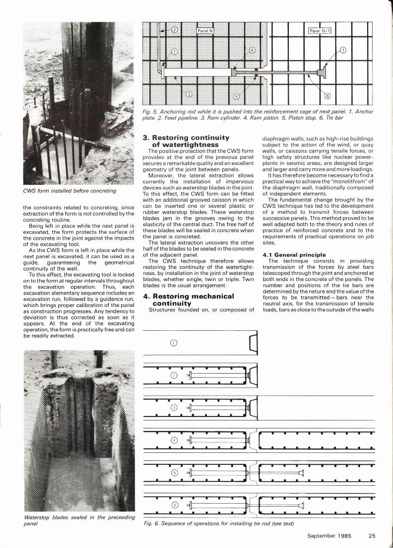
Fig. 6. Sequence of operations for installing tie rod (see text)

anchoring plate. It is pushed out of thecylinder by a fluid fed into the cylinder, untilthe piston rests on the thrust block at the endof the cylinder. (Fig. 5).
The various components of the ram(cylinder, anchor plates, piston, rod, thrustblock) are of suitable dimensions to carry thedesign loads.
pa~''„
$K (,,4'
~R.
Connecting device showing the positioning ofthe ram and tie rodin the reinforcement cages
as possible for the transmission of bendingmoments.
4.2. DispositionThe basic element is a single acting ram of
which the cylinder is the anchorage in a paneland the rod, after extending, is the anchoragein the adjacent panel.
Each elementary ram is thereforecomposed of:1.A fixed part which is the cylinder of the ramfitted at its end with an anchoring plate andconnected to a pipeline.2. A moving part composed of the piston androd. The rod is fitted at its end with an
l.kg ' ~ ~ ~
Detail: cylinder and anchoring plate
4.3. InstallationTo make it simple, the sketch of the
installation shows rams in the axis of the wall.Panel n has been excavated (Fig. 6), and
the CWS form is installed as usual at the endof the panel (1).
At the time of construction, thereinforcement cage has been fitted with therams necessary to transmit the design load.Each ram is installed in the cage facing paneln+ 1, with the piston and rod pulled in. All
the rams located near the same vertical planeare connected to the same vertical line whichwill feed pressure to them.
The reinforcing cage is installed in thepanel against the CWS form (2).The anchor-ing plates at the end of the rods are pressedagainst the CWS form by connecting thepipeline to a low pressure source.
Panel n is concreted (3). Adjacent paneln+ 1 is normally excavated while the CWSform protects the anchoring plates. The formis extracted. The reinforcing cage is loweredinto panel n+ 1 and care is taken to install it
so that no part of it can prevent the rods fromextending later (4). As the cage has beenconstructed for that purpose, this is achievedby just installing the cage at the proper level.
The rams sealed in panel n are thengrouted with a non-shrink cement by themeans of a double packer set in the pipelineopposite each ram in succession (5). It is thuspossible to make sure each rod andanchoring plate is pushed into thereinforcing cage of panel n+ 1 until thepiston rests on the thrust block.
The panel is then concreted, and the rodsand anchoring plates achieve a permanentmechanical bond between the twosuccessive panels (6).
4.4. Practical operationsNo major problem is engendered by the
method, regarding the usual rules ofreinforced concrete design. A few practicalpoints had to be checked, in particular thecorrect embedment of the variouscomponents in concrete.
Field testing has confirmed that themethod is well adapted to the usualconditions of the construction of diaphragmwalls. In fact, the rams can be installed in the
Detail: rod and anchoring plate
reinforcing cages without significant altera-tions. It is enough to add a few stiffeners andimprove accuracy in installation. Installationof the rams does not alter in any way thestandard operating procedures for theconstruction of diaphragm walls, andoperation of the rams themselves has littleinfluence on the sequence of work.
The method is very flexible, as the ramscan be installed at the places where forcesare located, and only at these places. Oncethe characteristics of the rams are chosen (inthe range of 50 to 100 tonnes in tensilestrength) their location can be adjusted tosuit the nature and intensity of the forces.
In conclusion, we must also explain thatcorrosion protection of the rods at the jointbetween panels is achieved by an epoxy resincoating a few inches long on both sides of thejoint.
Installation of waterstop blades asdescribed in the previous section is totallycompatible with the tie rods.
5. ProspectsThe CWS technique is a radical change in
the method for the construction ofdiaphragm walls. It can be carried out with allexisting excavation equipment —cablegrabs, hydraulic grabs, kelly equipment, rockmills, etc.
It represents an important step forward in
the quality of diaphragm wall construction. It
contributes to widening the field ofapplications for diaphragm walls by bringinga practically effective answer to problemsconnected with their discontinuous nature.
To this date 100 000m'f walls have beenconstructed by this method both in Franceand abroad in ten different countries in agreat variety of materials and, until now, asdeep as 35m.
r
~ i ka
-<orna
<,—,-gpss
3I,. 'g(j I
.r~ a8»t < k I I
Ramsin reinforcement cage
26 Ground Engineering
Tie rods extended through reinforcement cage of the next panel