Cutler-Hammer Branch/Feeder AFCI incorporating Ground ...pub/@electrical/documents/content/... ·...
25
File E45310 May 31, 2001 SPECIAL SERVICES INVESTIGATION ON BRANCH/FEEDER ARC FAULT CIRCUIT INTERRUPTER INCORPORATING EQUIPMENT GROUND FAULT PROTECTION Cutler-Hammer Technology & Quality Center 170 Industry Drive, RIDC Park West Pittsburgh, PA 15275
Transcript of Cutler-Hammer Branch/Feeder AFCI incorporating Ground ...pub/@electrical/documents/content/... ·...
File E45310
May 31, 2001
SPECIAL SERVICES INVESTIGATION
ON
BRANCH/FEEDER ARC FAULT CIRCUIT INTERRUPTER INCORPORATING EQUIPMENT GROUND FAULT PROTECTION
Cutler-Hammer
Technology & Quality Center 170 Industry Drive, RIDC Park West
Pittsburgh, PA 15275

File E45310
Project 01NK12396
May 31, 2001
SPECIAL SERVICES INVESTIGATION
ON
BRANCH/FEEDER ARC FAULT CIRCUIT INTERRUPTER
INCORPORATING EQUIPMENT GROUND FAULT PROTECTION
Cutler-Hammer Technology & Quality Center
170 Industry Drive, RIDC Park West Pittsburgh, PA 15275
Copyright © 2001 Underwriters Laboratories Inc.®
Underwriters Laboratories Inc. authorizes the above-named company to reproduce this Report provided it is reproduced in its entirety. In no event shall UL be responsible to anyone for whatever use or non-use is made of the information contained in this Report and in no event shall UL, its employees, or its agents incur any obligation or liability for damages including, but not limited to, consequential damage arising out of or in connection with the use or inability to use the information contained in this Report. Information conveyed by this Report applies only to the specimens actually involved in these tests. UL has not established a factory Follow-Up Service Program to determine the conformance of subsequently produced material, nor has any provision been made to apply any registered mark of UL to such material. The issuance of this Report in no way implies any additional Listing, Classification or Recognition by UL and does not authorize additional use of UL Listing, Classification or Recognition Marks or other reference to UL on or in connection with the product or system.
File E45310 Page 1 Issued: 5-31-01
INTRODUCTION At the present time the UL Standard for Arc-Fault Circuit-Interrupters (AFCIs) does not require AFCIs to detect a high-impedance fault condition known as a "glowing connection". Paragraph 1.3 of UL 1699 states:
These devices are not intended to detect glowing connections. The glowing connection has been documented by a number of technical investigators as a potential ignition mechanism. The purpose of this investigation was to assess the ability of a Branch/Feeder AFCI incorporating ground fault protection to respond to a glowing connection occurring at a wiring device termination. The ability to interrupt such a thermal event is seen as an additional mechanism by which AFCIs may be used to reduce the risk of electrical ignition. PLAN OF INVESTIGATION This investigation was divided into the following tasks:
TASK DESCRIPTION
1. Literature Search - Since this report may be distributed to persons unfamiliar with the glowing connection phenomenon, a number of technical articles describing the glowing connection were reviewed. A complete reference list and an abstract for each article are included as part of this report.
2. Review of Wiring Devices and Wiring Practices - The likelihood and
consequences of a glowing connection occurring at each of three different types of wiring devices typically found on a residential branch circuit was considered:
• Receptacle outlets • Switches • Lighting outlets
In each case this consideration took into account wiring device constructions as well as typical installations on a residential branch circuit. The appropriate UL Standards for each wiring device were reviewed as well as relevant National Electrical Code (NEC) requirements and customary wiring practices.
3. Laboratory Testing - A series of laboratory tests were performed to
assess the ability of an AFCI incorporating equipment ground fault detection to respond to a glowing connection.
4. Documentation of Data and Relationships - Laboratory test data were
correlated to published technical literature.

File E45310 Page 2 Issued: 5-31-01
TASK 1 - LITERATURE SEARCH: Familiarity with the glowing connection phenomenon is essential to: • An understanding of the potential fire hazard associated with such a
connection. • The assessment of whether or not a Branch/ Feeder Arc Fault Circuit
Interrupter (AFCI) may be capable of responding to a glowing connection thereby providing additional benefit to mitigating a potential fire hazard.
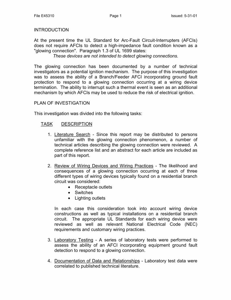
A glowing connection is a loose electrical connection that has developed into a high-resistance connection. This connection is characterized by a point of intense heating. Several amperes through the connection can be sufficient to cause the connection to attain temperatures that cause a copper wire to glow -- hence the name glowing connection. A number of investigators have examined this phenomenon as reported below. Some have concluded that the glowing connection is the result of an oxide formation. Others have indicated that they believe “micro-arcing” to be the cause. It is quite possible that such micro-arcing precipitates the formation of an oxide boundary layer between the conductor and the head of the screw terminal. The semi-conductive nature of this boundary layer may then account for the glowing connection. Having dissimilar metals in the connection like copper wire and a steel screw enhances joule heating. The heat from the arcing raises the temperature of the connection and within a few minutes, a low-pressure connection between the wire and the binding screw can begin glowing. Once established, a high-resistance terminal is fairly stable if it is not mechanically disturbed. The current through the high-resistance connection can be cycled without disrupting the high-resistance property. It will continue to glow when the current is high, but lower than the handle rating of a 15 A or 20 A overcurrent device. Figure 1 illustrates the damage to a receptacle caused by a glowing connection.
File E45310 Page 3 Issued: 5-31-01
Figure 1 - A Receptacle Damaged by a Glowing Connection
LITERATURE REVIEW Exploratory Study of Glowing Electrical Connections1 - Messrs. William J. Meese and Robert W. Beausoliel Abstract: The investigators were successful in over 100 attempts at producing a glowing connection with both aluminum and copper wiring when either wiring made loose contact with receptacles employing steel plated binding screws. In these experiments, the only physical parameters necessary to obtain and sustain glows were small contact area and/or small pressure at a contacting point in the conducting path. They hypothesized that with a slight loosening of the binding screw a small enough air gap is produced which may be breached at.120 volts. When the voltage is applied to the circuit, an arc is created at this gap or at some contact point of light pressure which is accompanied by high temperature, a glow and perhaps some vaporized metal. In their testing, a glow was produced when a steel receptacle binding screw was backed off 1/8 turn from being tightened to 2-inch pounds torque. In some cases they were able to produce a glow without vibration, wire disturbance or arcing. At other times, they were able to develop a glow with only the disturbance created when an attachment plug was inserted and removed from the receptacle. In still other cases, glows were only developed after severe vibrations or other severe disturbances.
1 William J. Meese & Robert W. Beasoliel, Exploratory Study of Glowing Electrical Connections, NBS Building Science Series 103, U.S. Dept. of Commerce, National Bureau of Standards, October 1977.

File E45310 Page 4 Issued: 5-31-01
Glowing Connections2 - Bruce Ettling Abstract: A series of experiments were conducted to demonstrate the amount of heating possible at a high resistance connection termed a glowing connection and how such a connection could produce an electrical fire. Rather than simulating actual connections, most of the experiments involved either copper or aluminum wires in contact with steel nails. Additional trials involved copper to copper and copper to aluminum contacts. In each experiment, the current was limited to normal load values. As a result of the experiments, it was concluded that an initial small area contact of “bare” metals has sufficient resistance to cause mild heating. This slow heating forms an oxide layer at the electrical interface. Once the higher resistance of the oxides is established, heating increases and the oxide layer thickens faster to the eventual point of producing a glowing connection. It was observed that the glowing connection could be established easily between iron and either copper or aluminum conductors. Glowing connections can be established between other combinations of metals but less readily and with less stability. The glow occurs at an interface of oxides and develops between a wire and what it is loosely connected to. The glowing connection is not a fault but represents a point of increased resistance in series with a normal load with normal current flow. Observations on the Mechanism of High Resistance Junction Formation in Aluminum Wire Connections3 - Dale Newbury, S. Greenwald Abstract: In this study, the basic mechanism of high resistance junction formation in duplex connectors wired with aluminum wire was investigated. Microstructural observations were made by scanning electron microscopy and X-ray microanalysis. Loose screw connections at the receptacle may result from one or more of the following causes:
1. Expansion and contraction of the connection – Heating caused by the I2R losses in the connection is the principal means of expansion and contraction.
2. Creep – Aluminum is a metal that may exhibit creep or relaxation under stress at ambient temperatures.
3. Workmanship – A receptacle in which the terminal screws are not sufficiently tightened during installation is a source of potential problems.
2 Bruce V. Ettling, "Glowing Connections", Fire Technology, pages 344-349, November 1982. 3 Dale Newbury & S. Greenwald, "Observations on the Mechanisms of High resistance Junction Formation an Aluminum Wire Connections", pages 429 - 440, Journal of Research of the National Bureau of Standards, Nov. - Dec. 1980.

File E45310 Page 5 Issued: 5-31-01
As a result of the experiments, it was concluded that: 1. The glow-arc process that occurs in mechanically loose aluminum
wire/iron screw and aluminum wire/brass plate connections results in locally high temperatures and causes material transport between the members of the connections.
2. Under these connections of high temperatures and intimate mixing the elements react to form intermetallic compounds, such as FeAl3 and CuAl2, and solid solutions.
3. The resistivity of these intermetallic compounds may be one of the main factors causing high resistance junction formation in these connections.
Glowing Contact Areas in Loose Copper Wire Connections4 - J. Sletbak, R. Kristensen, H. Sundklakk Abstract: Laboratory experiments have shown that when a current carrying, loose copper wire connection is exposed to mechanical vibrations, a layer of Cu2O grows to form a bridge between the contact members, bonding them to one another. Due to the strongly negative temperature coefficient of Cu2O at high temperatures, the current is concentrated in a thin glowing filament at or near the surface of the oxide bridge. The maximum temperature of this filament was found to be 1200 – 1300 degrees C. Under the action of this hot filament, a rapid oxidation of the copper continues until in the end most of the copper wires has been converted to Cu2O to a depth of a few tenths of a mm. As the corrosion proceeds, the power dissipation increases to values that can without doubt cause fire hazards if a similar situation occurs in electrical apparatus or installations. According to statistics, loose connections at broken wires are known to be the cause of many fires. The phenomenon described in this report explains how a temperature high enough to cause a fire can arise, even when the connection is limited by the load impedance to values less than 1 A.
4 J. Sletback, et al., "Glowing Contact Areas in Loose Copper Wire Connections", IEEE, 1991.

File E45310 Page 6 Issued: 5-31-01
TASK 2 - REVIEW OF WIRING DEVICES AND WIRING PRACTICES: WIRING DEVICES - RECEPTACLE OUTLETS Of the three wiring devices considered, receptacle outlets are the most abundant wiring device to be found in a residence. Section 210-52(a) of the National Electrical Code (NEC) requires that:
In every kitchen, family room, dining room, living room, parlor, library, den, sunroom, bedroom, recreation room, or similar room or area of dwelling units, receptacle outlets shall be installed so that no point along the floor line in any wall space is more than 6 feet, measured horizontally, from an outlet in that space….
Receptacles may be divided into 4 grade levels as follows:
• Residential grade • Specification grade • Federal specification grade • Hospital grade
Since this investigation was limited to residential applications, hospital grade receptacles were not included. Of the remaining three grades, receptacles were selected on the basis of design features to be evaluated rather than a specified grade. It is acknowledged that some of the desired design features may not have been available in every grade level. Grounding - Since 1962, all receptacles installed on 15 A and 20 A branch circuits have been required to be of the grounding type by the NEC. Non grounding type receptacles are still manufactured and commercially available but these receptacle are intended for "replacement use" only within residences built prior to 1962 and not provided with a grounding wire electrical system. The National Electrical Code does not permit the use of non-grounding receptacles in new home constructions and only grounding type receptacles were considered in this investigation. Wire Termination - Receptacles may be typically connected to the building wiring system using one of the following methods:
• Back-wired push-in • Side-wired screw terminals • Back-wired side clamp
It should be noted that a receptacle may be provided with more than one wire termination method on a single wiring device. It is not uncommon, for example, to find a receptacle having provisions for both back-wired push-in connections in addition to side-wired screw terminals. Where a choice of wiring termination methods is provided, the particular installer will decide which termination method

File E45310 Page 7 Issued: 5-31-01
to use. Photos showing each type of wiring configuration are shown in Figures 2, 3 and 4. Figures 2 and 3 represent the same receptacle provided with both back wired push-in connections and side-wired screw terminals. Figure 2 - Back-wired push-in
Figure 3 - Side-wired screw terminals
Figure 4 - Back-wired side clamp

File E45310 Page 8 Issued: 5-31-01
The predominance of the researchers investigating the glowing connection phenomenon selected wire terminations under wire binding screws for their studies. This may be due in part to the large number of receptacles manufactured with such terminations or the relative ease by which a glowing connection can be created in a laboratory environment using this type of wiring termination. For the purpose of this investigation only receptacles provided with side-wired screw terminals were evaluated. Receptacles with side-wired screw terminals may be manufactured with either brass or plated steel binding screws. Although steel (plated or unplated) is not normally permitted as a current carrying part, the use of plated steel wire-binding screws is permitted in UL 498 - the Standard for Attachment Plugs and Receptacles in accordance with paragraph 10.1.2.
10.1.2 A steel that is corrosion-resistant (stainless) or is protected against corrosion by cadmium plating, zinc plating, or an equivalent protective coating, may be used for wire-binding nuts and screws if these parts are not depended upon to carry current.
If the wire-binding screw is properly tightened when the building wire is attached to the receptacle, the wire-binding screw is intended to only hold the wire in good electrical contact with the terminal on the receptacle and the wire binding-screw is not a part of the current carrying path. However, in the event that the wire-binding screw is improperly tightened during connection, the screw may loosen if the receptacle is subjected to repeated vibration or other mechanical manipulation such as repeated plugging and unplugging appliance loads. As shown in Figure 5 below, one reference source contends that the mere act of pushing the wired receptacle into the electrical box after assembly exerts forces on the wire binding screws that may tend to loosen some of them. In the event that a wire-binding screw does become loosened such that the current carrying path includes the steel screw, the creation of a glowing connection is possible.

File E45310 Page 9 Issued: 5-31-01
Figure 5 - Forces Exerted on a Receptacle5.
Receptacle outleUnder the descrconnection of eitpolarity glowing c Ground Yoke - mounting purposthe receptacle. Tand serves as thprovided on the receptacle. The the ground yoke. paragraph 14.1 in
14.1 Exceptspacing throdevice ratedmore than between angrounded orintended.
Materials - Recematerial. Whereheat distortion prenhanced ability part of this invesused for the face 5 W. J. Meese & R.WNBS Building SciencIssued November, 19
ts have both polarity circuit conductors connected to the device. ibed circumstances, a glowing connection may occur at the her the black wire or the white wire. In this evaluation, both onnections were considered.
Most receptacles are provided with a steel ground yoke for es. This yoke may either be internal or external to the body of he ground yoke provides mechanical support for the receptacle e grounding member. A green hexagonal shaped screw is
ground yoke for connection of a system grounding wire to the two grounding contacts on a duplex receptacle are connected to In order to maintain the minimum electrical spacing specified in UL 498, internal barriers are molded into the receptacle body.
where greater spacings are required in 33.4, there shall be a ugh air or over surface of not less than 3/64 inch (1.2 mm) for a 250 V or less, and not less than 1/8 inch (3.2 mm) for a device rated 250 V, between uninsulated live parts of opposite polarity and uninsulated live part and a dead-metal part that is likely to be exposed to contact by persons when the device is installed as
ptacle bodies may be either a thermoplastic or thermoset as a thermoset material has certain advantages with regard to operties, thermoplastic materials are gaining favor due to their to resist mechanical abuse without cracking or breaking. As tigation a simple test was performed to identify the materials and rear enclosure of each receptacle.
. Beausoliel, Evaluation of Electrical Connections for Branch circuit Wiring, e Series 128, U.S. Dept. of Commerce, National Bureau of Standards, 80.
File E45310 Page 10 Issued: 5-31-01
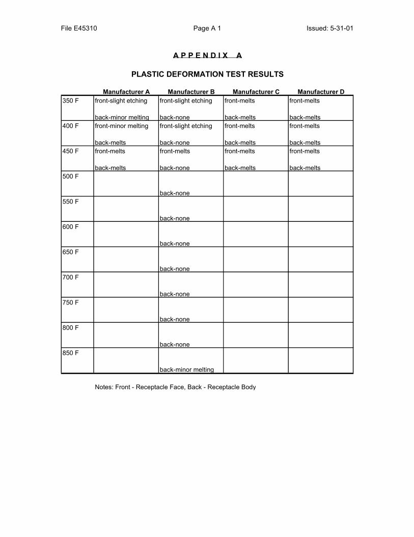
A soldering iron with a variable tip temperature was applied to each material and it was observed whether or not melting of the material occurred. If the material resisted melting at a temperature of 260 degrees Celsius (500 degrees F), it was judged to be a thermoset material. Materials that melted at lower temperatures were judged to be a thermoplastic. No attempt was made to further identify any of the materials used. The results of the Heat Deformation Test are reported in Appendix A. The receptacles made by manufacturers A, C and D employed thermoplastic materials in their receptacle construction (face and body). The receptacle made by manufacturer B employed a thermoplastic material for the receptacle face and a thermoset material for the receptacle body. As explained in Task 4, knowledge of the wiring device material was considered important to this investigation in order to assess the likely damage that the heating generated by a glowing connection could produce. Thermoplastics would melt whereas thermosets would pyrolyse and char.

File E45310 Page 11 Issued: 5-31-01
WIRING DEVICES - SWITCHES Another very common residential wiring device is the switch. The NEC requires that every habitable room and bathroom in a residence be provided with a switch to control the lighting in that room. In specified rooms, the switch may control either a lighting outlet (overhead fixture) or a receptacle outlet for connection of table or floor lamps. If a room has a single entry and exit point, a single pole single throw (SPST) switch is provided. If the room has more than one entry or exit point it is desirable to provide a switch at each point so that the room lighting can be controlled without necessitating walking through a darkened room either before or after turning on/off the room lights. In the case of a room with two entry/exit points, two three-way (single pole, double throw - SPDT) switches are provided, one located at each entry/exit point. In accordance with the NEC the switch is always located in the "hot" conductor. Depending upon the branch circuit feed to the lighting outlet to be controlled, it may be necessary to wire the switch into a switch leg. The wiring to a switch leg is illustrated in Figure 6. In this case a grounded circuit conductor is not present in the switch box and the "white" conductor must be taped black to indicate it is "hot". Figure 6 - Switch Leg6
6 Rex Cauldwell, Safe Home Wiring Projects, Taunton Books, Newton, CT, 1997.

File E45310 Page 12 Issued: 5-31-01
Wiring Terminations - Switches may be provided with either push-in connections or side wired binding-screws as previously described for receptacles. It is not uncommon to find a switch provided with both. Wire binding screws. As with receptacles, the Standard for General Use Snap Switches (UL 20) permits the use of either brass or plated steel screws in accordance with paragraph 9.1.3.
9.1.3 Steel that is corrosion-resistant (stainless) or steel that is protected against corrosion by cadmium plating, zinc plating, or an equivalent coating may be used for wire-binding nuts and screws and for a clamp or a clip for holding a conductor against a push-in (screwless) terminal if the steel parts are not depended upon to carry current.
Grounding - In accordance with UL 20, a flush mounted switch may be provided with a steel yoke or strap for mounting the switch to the electrical box. The wiring system grounding conductor is connected to the yoke (or strap) typically by means of a grounding lug made a part of the yoke and is secured by a green colored screw with a hexagonal head. This construction is similar to the grounding means provided on the receptacle. One noted difference is that no part of the grounding member including assembly screws or rivets enters the arc chamber of a switch whereas the grounding member on a receptacle must enter the receptacle body for attachment to the receptacle grounding contacts. In a receptacle, the ground must be accessible by the grounding pin on a grounded plug.
File E45310 Page 13 Issued: 5-31-01
WIRING DEVICES - LIGHTING OUTLETS As defined by the NEC, a lighting outlet is an outlet intended for the direct connection of a lampholder, a lighting fixture, or pendant cord terminating in a lamp holder.
Terminals - As with receptacles and switches, the UL Standard for Edison Base Lampholders (UL 496) permits such lampholders to be provided with steel plated wire binding screws as noted in paragraphs 11.2.1 and 11.2.2.
11.2.1 Iron or steel, plain or plated, shall not be used for parts that are depended upon to carry current. Exception: A corrosion-resistant (stainless–steel) alloy may be used for wire-binding nuts and screws and also for current-carrying parts that are not subjected to arcing. 11.2.2 Steel that is protected against corrosion by cadmium plating, zinc plating, or equivalently protective coating may be used for wire-binding nuts and screws that are not depended upon to carry current.
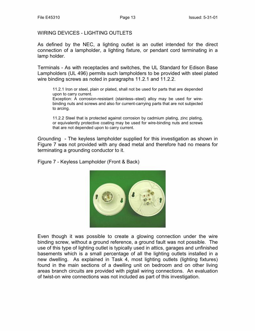
Grounding - The keyless lampholder supplied for this investigation as shown in Figure 7 was not provided with any dead metal and therefore had no means for terminating a grounding conductor to it. Figure 7 - Keyless Lampholder (Front & Back)
Even though it was possible to create a glowing connection under the wire binding screw, without a ground reference, a ground fault was not possible. The use of this type of lighting outlet is typically used in attics, garages and unfinished basements which is a small percentage of all the lighting outlets installed in a new dwelling. As explained in Task 4, most lighting outlets (lighting fixtures) found in the main sections of a dwelling unit on bedroom and on other living areas branch circuits are provided with pigtail wiring connections. An evaluation of twist-on wire connections was not included as part of this investigation.

File E45310 Page 14 Issued: 5-31-01
Materials - UL 496 permits the following insulating materials to be used: 1. Thermoplastic 2. Thermoset 3. Ceramic
WIRING All of the testing performed utilized type NM-B 2 conductor cable provided with a bare grounding conductor. The majority of the testing was performed using 14 AWG copper conductors with limited testing performed using 12 AWG aluminum conductors. Electrical grade copper has a melting point of approximately 1083 degrees Celsius whereas aluminum melts at approximately 660 degrees Celsius. Both conductor materials were included in this evaluation in order to:
1. Assess the ease of creating a glowing connection with either conductor metal
2. Determine if the lower melting point of aluminum would cause the aluminum conductor to melt or break and interrupting a glowing connection prior to the AFCI detecting a ground fault.

File E45310 Page 15 Issued: 5-31-01
TASK 3 - LABORATORY TESTING: TEST METHOD Except where noted, testing was performed using wiring devices provided by Cutler-Hammer. Underwriters Laboratories Inc. neither selected the samples nor determined whether they were representative of the finished assembly. The results apply to the samples tested. A glowing connection was created in the laboratory by making a loose connection on a steel plated wire-binding screw terminal on a wiring device such as a receptacle. The loose connection was manipulated with load current flowing to cause heating between the wire and the screw terminal due to repetitive arcing. For the testing performed, the load current was provided by individual space heaters having a rating of 1500 watts. In some cases the conductor welded to the terminal by the arcing. In these cases the wire was either further manipulated or the head of the wire binding screw rotated using a screwdriver to break the weld and arcing continued. Once a stable glowing connection was produced, it was left undisturbed until the ultimate results were noted. Where the glowing connection persisted for a lengthy period of time, overnight operation was not permitted. In some cases, as soon as voltage was applied the next day, a glowing connection was re-established. In other cases, a brief period of manipulation was required to re-establish the glowing connection. For this testing, each wiring device was connected to a branch circuit limited to an estimated available short circuit current ranging from 110 - 125 Amperes. A Branch/Feeder AFCI device in a circuit breaker configuration and incorporating equipment ground fault protection (30mA trip level) was located in each test circuit. Each wiring device was mounted in a plastic outlet box having no grounded dead metal. NM-B wiring having a bare grounding conductor was connected to the ground lug provided on each receptacle and switch. In the case of the single lighting outlet tested, no ground lug was provided and the bare grounding conductor was left unconnected. Each conductor was carefully routed within the outlet box to the wiring device such that no two conductors were in contact with each other. The black and white insulated conductors were also carefully routed such that they did not contact the grounding member on the wiring device under test. A photo of the test set-up is shown in Figure 8 and an individual receptacle under test is shown in Figure 9.

File E45310 Page 16 Issued: 5-31-01
Figure - 8 Test Set-Up
Figure 9 - Individual Receptacle Under Test

File E45310 Page 17 Issued: 5-31-01
Representative damage observed with glowing connections is shown in Figures 10 and 11. Figure 10 - Receptacle Damaged by a Glowing Connection
Figure 11 - Switch Damaged by a Glowing Connection
The test results are reported in Appendix B. Observations and analysis of the test results are included as part of Task 4 below.

File E45310 Page 18 Issued: 5-31-01
TASK 4 - DOCUMENTATION OF DATA AND RELATIONSHIPS: LEAKAGE CURRENTS AND DIFFERENTIAL CURRENTS Leakage current is often thought of as the electrical current which flows through a person upon contact with an accessible part of an appliance while that person is grounded or between two accessible parts. The IEEE Dictionary gives several definitions for leakage current depending upon the intended application. For example, the definition applicable to health care facilities describes leakage current as any current, including capacitively coupled current, not intended to be applied to a patient but which may be conveyed from exposed metal parts of an appliance to ground or other accessible parts of an appliance. Another IEEE definition relative to insulation resistance defines leakage current as the current that flows through (including defects) in the insulation, and across the insulation surface itself. Most grounded electrical products will have a small inherent amount of leakage current present even under normal conditions. This current does not flow through a person's body, but through the electrical system equipment grounding conductor and is more appropriately referred to as differential current. In addition to the standing differential current from the electrical products used in the home, the amount of differential current which flows in a residential electrical distribution system is also a function of the system voltage and the quality of the insulation used in permanent wiring and built-in wiring devices. A small amount of both differential current and unwanted across-the-line current is normal for any type of insulation system. With time, the quality, of the insulation system may deteriorate. This may be due to physical damage, voltage surges overstressing the insulation, contaminants, temperature degradation, etc. In the case of thermal degradation produced by a glowing connection, the insulation on both the wiring and the wiring device has been demonstrated to degrade very quickly. As the quality of the insulation system deteriorates, the amount of differential current increases. An AFCI incorporating equipment ground fault protection functions by using a differential transformer to sense the difference in current in the conductors supplying power to the circuit being protected. If the differential current exceeds a predetermined value (e.g. 30 mA), the Branch/Feeder AFCI will trip. Thus the overheating of the wiring devices and/or the wires leading to those devices can result in differential currents to ground.

File E45310 Page 19 Issued: 5-31-01
TEST RESULTS The results of the testing are summarized in Appendix B. A glowing connection was readily created using both copper and aluminum conductors. In some cases the heating produced by the glowing connection caused the conductor to break and interrupt the glowing connection prior to the AFCI opening the circuit. With reference to receptacle testing, a total of 16 tests were performed. In 6/16 tests the glowing connection terminated because the wire burned open. Of significance, however, in 9/16 tests the Branch/Feeder AFCI terminated the glowing connection and provided enhanced protection. In the case of the switches tested, testing was frequently interrupted when heat deformation of the switch body (created by the glowing connection) caused the switch contacts to separate and interrupt the load. This opened the circuit to a safe condition. It was noted that the Branch/Feeder AFCI did respond to a ground fault on one of the switches tested. In the case of the lighting outlet tested, the keyless lampholder was not provided with any "dead metal" and there was no provision for grounding this wiring device. In the absence of a grounding member a ground fault was not possible and as expected the AFCI tested did not trip. It should be noted that this type of outlet is typically found in attics, garages and unfinished basements. Its use is no longer permitted by the NEC in bedroom closets, due to a concern for potential ignition of clothing stored on the upper shelf in the closet. Typically lighting outlets used for a bedroom and living areas would consist of a lighting fixture supported by an outlet box. Such lighting fixtures are generally provided with pigtail leads and are connected to the branch circuit by means of twist on wire connectors. These test results were obtained using non-metallic outlet boxes and with conductors intentionally separated. The enhanced protection provided by a Branch/Feeder AFCI incorporating equipment ground fault protection could be expected to be greater had metallic boxes and/or conventional field wiring practices been used (no deliberate physical separation).

File E45310 Page 20 Issued: 5-31-01
MAGNITUDE OF THE PROBLEM The CPSC report titled What Causes Wiring Fires in Residences?7, examined fire statistics for fires originating in the electrical distribution system. As part of this investigation, the failure modes involved in 149 residential electrical distribution system fires were examined by component. It was found that receptacle outlets and switches accounted for 29 (19%) of the fires. Twenty-six of the 29 investigated fires were attributed to electrical system components associated with receptacle outlets. Where a cause could be determined, the most frequent problem cited was "loose connection," which was either a loose fit between the outlet contacts or a loosening of the wire connection to the receptacle. In some cases it was reported that copper wires were inadequately secured during initial installation so as to cause subsequent deterioration and overheating. Lighting fixtures and lamps accounted for an additional 19 (13%) of the fires. The most common problem noted in lighting fixtures and lamps was poor workmanship, as evidenced by loose or otherwise defective connections that caused wires and insulation to overheat. SUMMARY The purpose of this investigation was to assess the ability of a Branch/Feeder AFCI incorporating ground fault protection to respond to a glowing connection occurring at a wiring device termination. The investigation considered cases of glowing connections occurring at either the interface between the insulated (black) ungrounded circuit conductor and the wiring device terminal; or between the insulated (white) grounded circuit conductor and the wiring device terminal. By test design, a physical separation was maintained between the two insulated conductors and between each insulated conductor and ground. By virtue of this worst case configuration*, it was demonstrated that a Branch/Feeder AFCI incorporating equipment ground fault protection (30 mA trip) is capable of terminating a glowing connection and the associated heating effects by sensing the differential current associated with thermal degradation of the wiring device insulating material(s). (* Worst case configuration refers to the deliberate prevention of tripping by the Branch/Feeder AFCI incorporating ground fault protection due to contact between overheated circuit conductors, or between either of the heated circuit conductors and ground.)
7 Linda E. Smith & Dennis McCoskrie, "What Causes Fires in Residences?", Fire Journal, January/February 1990.

File E45310 Page 21 Issued: 5-31-01
REPORT BY: REVIEWED BY: RICHARD V. WAGNER DAVID A. DINI Senior Research Engineer Senior Research Engineer Research Department Research Department
File E45310 Page A 1 Issued: 5-31-01
A P P E N D I X A
PLASTIC DEFORMATION TEST RESULTS
Manufacturer A Manufacturer B Manufacturer C Manufacturer D350 F front-slight etching front-slight etching front-melts front-melts
back-minor melting back-none back-melts back-melts400 F front-minor melting front-slight etching front-melts front-melts
back-melts back-none back-melts back-melts450 F front-melts front-melts front-melts front-melts
back-melts back-none back-melts back-melts500 F
back-none550 F
back-none600 F
back-none650 F
back-none700 F
back-none750 F
back-none800 F
back-none850 F
back-minor melting
Notes: Front - Receptacle Face, Back - Receptacle Body

File E45310 Page B 1 Issued: 5-31-01
A P P E N D I X B
GLOWING CONNECTION TEST RESULTS
Test Wiring Device Mfr. Wire Did AFCI Trip?1.1 Receptacle A Cu Y1.2 Receptacle E Cu 11.3 Receptacle B Cu Y1.4 Receptacle A Cu Y1.5 Receptacle A Cu Y2.1 Receptacle D Cu Y2.2 Receptacle A Cu Y2.3 Switch C Cu 22.4 Switch D Cu 22.5 Switch A Cu 22.6 Switch C Cu Y2.7 Switch D Cu 22.8 Receptacle B Al 33.1 Receptacle C Cu Y3.2 Switch B Cu 24.1 Receptacle B Cu 15.1 Receptacle A Cu Y5.2 Receptacle A Cu Y5.3 Switch A Cu 25.4 Switch B Cu 26.1 Receptacle D Cu 16.2 Lamp Base A Cu N7.1 Receptacle C Cu 17.2 Receptacle B Cu 18.1 Receptacle B Cu 1
Notes: 1 - Wire burned open.2 - Heat distortion caused switch contacts to open.3 - Test continued for 35 hours. Arbitrarily terminated.