Cu0109 - Fire Cable Sizing - V2
20
7/25/2019 Cu0109 - Fire Cable Sizing - V2 http://slidepdf.com/reader/full/cu0109-fire-cable-sizing-v2 1/20 APPLICATION NOTE FIRE SAFETY CABLES Selection and sizing of conductors supplying electrical equipment that must remain functional during a fire J. Wiatr, Z. Hanzelka, S. Fassbinder, D. Chapman June 2014 ECI Publication No Cu0109 Available from www.leonardo-energy.org
-
Upload
rafael-feria -
Category
Documents
-
view
240 -
download
1
Transcript of Cu0109 - Fire Cable Sizing - V2
7/25/2019 Cu0109 - Fire Cable Sizing - V2
http://slidepdf.com/reader/full/cu0109-fire-cable-sizing-v2 1/20
APPLICATION NOTE
FIRE SAFETY CABLES
Selection and sizing of conductors supplying electrical equipment thatmust remain functional during a fire
J. Wiatr, Z. Hanzelka, S. Fassbinder, D. Chapman
June 2014
ECI Publication No Cu0109
Available from www.leonardo-energy.org
7/25/2019 Cu0109 - Fire Cable Sizing - V2
http://slidepdf.com/reader/full/cu0109-fire-cable-sizing-v2 2/20
Publication No Cu0109
Issue Date: June 2014
Page i
Document Issue Control Sheet
Document Title: Application Note – Fire Safety Cables
Publication No: Cu0109
Issue: 03
Release: June 2014
Author(s): J. Wiatr, Z.Hanzelka, D. Chapman, S. Fassbinder
Reviewer(s): Roman Targosz
Document History
Issue Date Purpose
1 December
2010
Initial publication
2 September
2011
Improved and summary added, to publish it in the framework of the LE Good Practice
Guide
3 June 2014 Reviewed
Disclaimer
While this publication has been prepared with care, European Copper Institute and other contributors provide
no warranty with regards to the content and shall not be liable for any direct, incidental or consequential
damages that may result from the use of the information or the data contained.
Copyright© European Copper Institute.
Reproduction is authorised providing the material is unabridged and the source is acknowledged.

7/25/2019 Cu0109 - Fire Cable Sizing - V2
http://slidepdf.com/reader/full/cu0109-fire-cable-sizing-v2 3/20
Publication No Cu0109
Issue Date: June 2014
Page ii
CONTENTS
Summary ........................................................................................................................................................ 1
Introduction .................................................................................................................................................... 2
The development of a fire ............................................................................................................................... 2
Fire safety cables ............................................................................................................................................ 5
Selection and erection ............................................................... ................................................................. ............ 5
Cable construction ........................................................................................... ....................................................... 6
Conductor Sizing ................................................................................... .............................................................. .... 8
Current-carrying capacity ..................................................................................................................................... 10
Circuit protection ............................................................ ................................................................. ..................... 11
Voltage drop .............................................................................. .............................................................. ............. 14
Motor starting currents ................................................................................................................... ..................... 14
Physical installation .............................................................................................................................................. 16
Conclusion .................................................................................................................................................... 17

7/25/2019 Cu0109 - Fire Cable Sizing - V2
http://slidepdf.com/reader/full/cu0109-fire-cable-sizing-v2 4/20
Publication No Cu0109
Issue Date: June 2014
Page 1
SUMMARY
Cables that are exposed to fire while being expected to retain their functionality and provide power to
essential equipment at another location must be appropriately selected and sized. This is not only a question
of an appropriate insulation. Designers must take account of the increased electrical resistance at elevated
temperature.
Manufacturers offer cables and accessories that will survive a standard cellulose fire for 30, 60 or 90 minutes
when correctly specified and installed.
A first step to specifying a suitable fire safety cable is a good knowledge of the temperature rise characteristic
in areas affected by the fire.
A second step is the correct selection and erection of the cable. This includes the correct sizing of the
conductor. Cables, including fire safety cables, are specified in terms that reflect their normal duty conditions;
design parameters under fire conditions are rarely, if ever, specified. The designer must take into account the
consequent effects of the increased electrical resistance on current carrying capacity, voltage drop, short
circuit capacity and mechanical strength of the conductors. Special care should go to the current carrying
capacity of the conductor if it is to supply electrically driven fire pumps or elevators required for firefighting,
since their motors could draw high starting currents. The circuit protection and related values (e.g. the touch
voltage level) should also be adapted to fire conditions, as it must be designed to function with significant
higher loop impedance than normal.
This paper provides a clear methodology for designing fire safety circuits based on the derivation and
application of correction factors and standard cable parameters.
Having selected the appropriate cable, it must be installed properly, using suitable accessories and following
the manufacturer’s restrictions.

7/25/2019 Cu0109 - Fire Cable Sizing - V2
http://slidepdf.com/reader/full/cu0109-fire-cable-sizing-v2 5/20
Publication No Cu0109
Issue Date: June 2014
Page 2
INTRODUCTION
The maintenance of safety services in a building during an emergency is vital if the situation is to be contained
and the lives of occupants and emergency workers preserved. The first objective is to provide, as far as
possible, safe evacuation routes from the affected areas and to ensure that all services required for fighting
the fire are maintained for the required time. Another objective may be to ensure the preservation of servicesin areas of the building not directly affected by fire to provide a safe environment for evacuees from affected
areas, pending complete evacuation, or the end of the incident. Finally, the preservation of property is
important.
The time for which safety services are required to operate depends on the use of the building and the number
and type of occupants involved. While it may be feasible to evacuate a dwelling or a small office building in a
short time, larger or higher buildings, or those used by the public will take much longer1. The longer that safety
services remain operational, the better the chance of bringing a fire under control and reducing property
damage.
THE DEVELOPMENT OF A FIRE
The key to specifying a suitable fire safety cable is a good knowledge of the temperature rise characteristic in
areas affected by the fire. Although the exact process depends on the location and materials involved,
temperature-time curves have been developed to model some typical fires and are defined in standard EN
1363-2:1999:
Standard temperature-time curve
Hydrocarbon curve
External fire exposure curve
Parametric temperature-time curves
Tunnel curves
The best known of these is the standard temperature-time curve illustrating cellulose fires, which is commonly
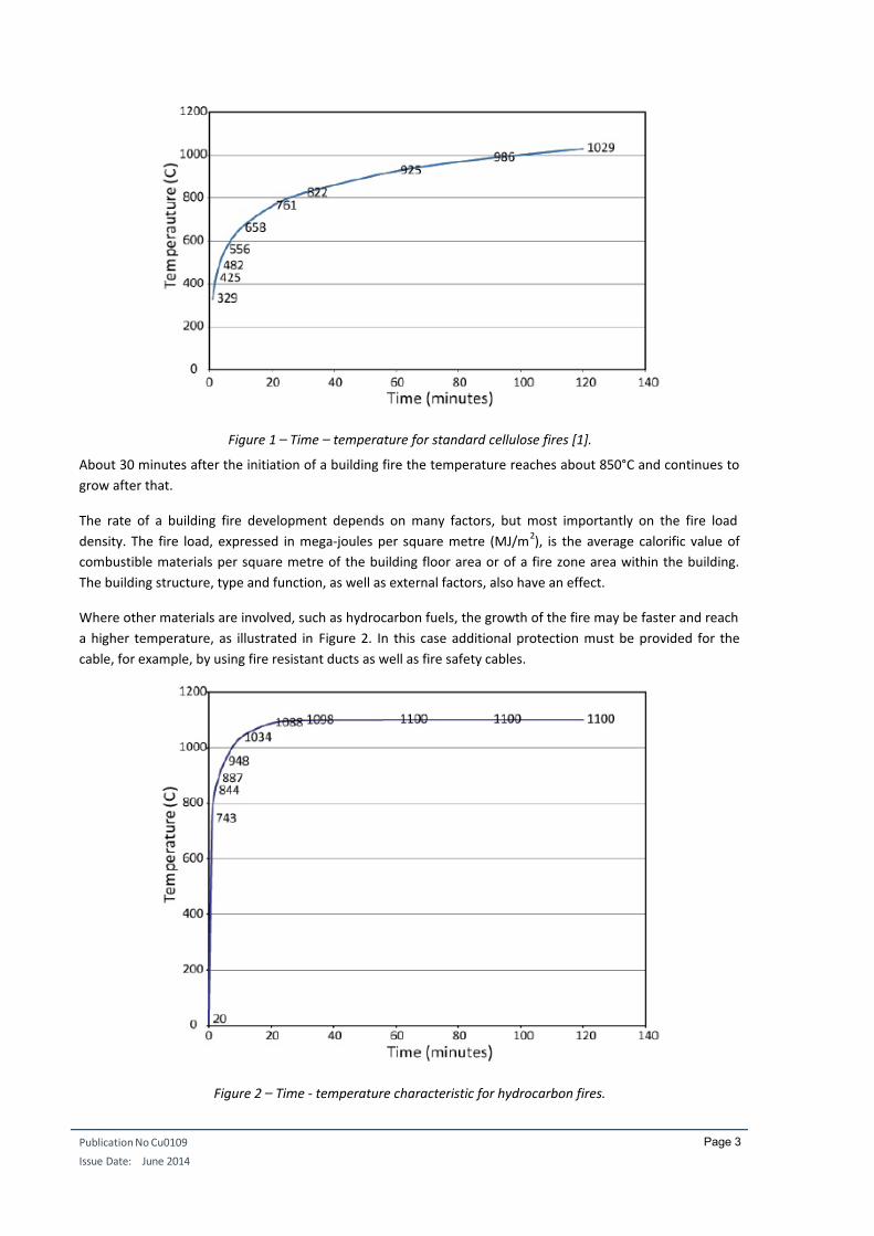
used in the fire-testing of buildings. The standard temperature-time curve is expressed by the formula:
= 345 log8 + 1 + 20
where:
T – temperature, in C
t – time, in minutes
Figure 1 shows the temperature rise against time curve of the development of a cellulose-fuelled fire i.e. a fire
fuelled mainly by wood and wood-based materials such as paper.
1
Following an explosion in World Trade Center 1 in 1993, the evacuation took more than 4 hours during whichover 1000 people were injured, many due to smoke inhalation. Fortunately, the fire had been extinguished.
7/25/2019 Cu0109 - Fire Cable Sizing - V2
http://slidepdf.com/reader/full/cu0109-fire-cable-sizing-v2 6/20
Publication No Cu0109
Issue Date: June 2014
Page 3
Figure 1 – Time – temperature for standard cellulose fires [1].
About 30 minutes after the initiation of a building fire the temperature reaches about 850°C and continues to
grow after that.
The rate of a building fire development depends on many factors, but most importantly on the fire load
density. The fire load, expressed in mega-joules per square metre (MJ/m2), is the average calorific value of
combustible materials per square metre of the building floor area or of a fire zone area within the building.
The building structure, type and function, as well as external factors, also have an effect.
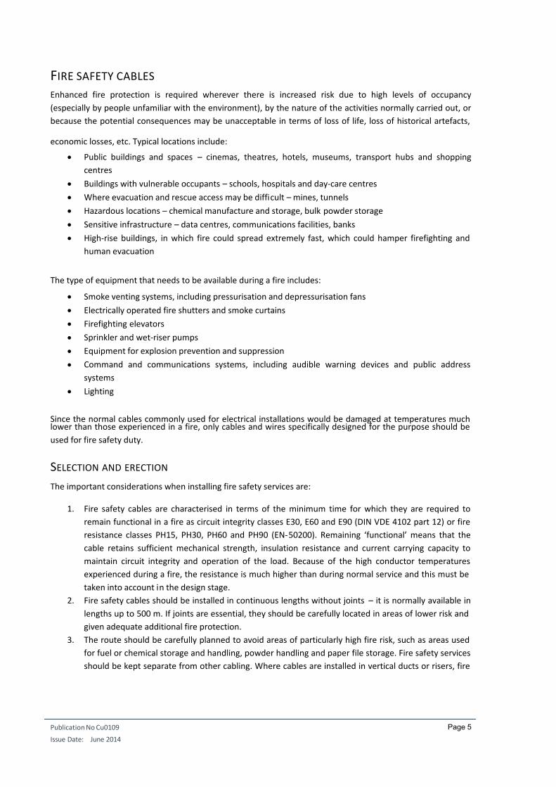
Where other materials are involved, such as hydrocarbon fuels, the growth of the fire may be faster and reach
a higher temperature, as illustrated in Figure 2. In this case additional protection must be provided for the
cable, for example, by using fire resistant ducts as well as fire safety cables.
Figure 2 – Time - temperature characteristic for hydrocarbon fires.

7/25/2019 Cu0109 - Fire Cable Sizing - V2
http://slidepdf.com/reader/full/cu0109-fire-cable-sizing-v2 7/20
Publication No Cu0109
Issue Date: June 2014
Page 4
The characteristic of a tunnel fire is shown in Figure 3. This curve was developed by the Rijkswaterstaat
(ministry of transport) in the Netherlands. It is based on the assumption that, in a worst case scenario, a 50 m³
fuel, oil or petrol tanker fire with a fire intensity of 300 MW could occur, lasting up to 120 minutes. The curve
was based on the results of testing carried out in the Netherlands in 1979 and recently confirmed in full-scale
tests in the Runehamar tunnel in Norway.
Figure 3 – Time - temperature for tunnel fires.
These graphs illustrate the models used for testing and assessment of fire protection materials. Real fires are
different in that the temperature profile is far from constant. For example, in the Channel Tunnel fire in 1996,which burned for seven hours, the general temperature is thought to have reached around 800 °C with hot
spots of up to 1300 °C where hydrocarbons were locally involved.
7/25/2019 Cu0109 - Fire Cable Sizing - V2
http://slidepdf.com/reader/full/cu0109-fire-cable-sizing-v2 8/20
Publication No Cu0109
Issue Date: June 2014
Page 5
FIRE SAFETY CABLES
Enhanced fire protection is required wherever there is increased risk due to high levels of occupancy
(especially by people unfamiliar with the environment), by the nature of the activities normally carried out, or
because the potential consequences may be unacceptable in terms of loss of life, loss of historical artefacts,
economic losses, etc. Typical locations include:
Public buildings and spaces – cinemas, theatres, hotels, museums, transport hubs and shopping
centres
Buildings with vulnerable occupants – schools, hospitals and day-care centres
Where evacuation and rescue access may be difficult – mines, tunnels
Hazardous locations – chemical manufacture and storage, bulk powder storage
Sensitive infrastructure – data centres, communications facilities, banks
High-rise buildings, in which fire could spread extremely fast, which could hamper firefighting and
human evacuation
The type of equipment that needs to be available during a fire includes:
Smoke venting systems, including pressurisation and depressurisation fans
Electrically operated fire shutters and smoke curtains
Firefighting elevators
Sprinkler and wet-riser pumps
Equipment for explosion prevention and suppression
Command and communications systems, including audible warning devices and public address
systems
Lighting
Since the normal cables commonly used for electrical installations would be damaged at temperatures muchlower than those experienced in a fire, only cables and wires specifically designed for the purpose should be
used for fire safety duty.
SELECTION AND ERECTION
The important considerations when installing fire safety services are:
1. Fire safety cables are characterised in terms of the minimum time for which they are required to
remain functional in a fire as circuit integrity classes E30, E60 and E90 (DIN VDE 4102 part 12) or fire
resistance classes PH15, PH30, PH60 and PH90 (EN-50200). Remaining ‘functional’ means that the
cable retains sufficient mechanical strength, insulation resistance and current carrying capacity to
maintain circuit integrity and operation of the load. Because of the high conductor temperatures
experienced during a fire, the resistance is much higher than during normal service and this must be
taken into account in the design stage.
2. Fire safety cables should be installed in continuous lengths without joints – it is normally available in
lengths up to 500 m. If joints are essential, they should be carefully located in areas of lower risk and
given adequate additional fire protection.
3. The route should be carefully planned to avoid areas of particularly high fire risk, such as areas used
for fuel or chemical storage and handling, powder handling and paper file storage. Fire safety services
should be kept separate from other cabling. Where cables are installed in vertical ducts or risers, fire

7/25/2019 Cu0109 - Fire Cable Sizing - V2
http://slidepdf.com/reader/full/cu0109-fire-cable-sizing-v2 9/20
Publication No Cu0109
Issue Date: June 2014
Page 6
stops must be provided2 (as is required for all cables) to prevent fire spread in the event that the
enclosure is breached. All cable accessories (mounting clips, etc.) should have a fire rating similar to
that of the cable to avoid the extra mechanical stress that could occur in the event of failure of
restraining clips. Installation restrictions, such as minimum bend radius, should be strictly observed.
Fire safety services must be installed above a sprinkler system to avoid contact with water, which
would rapidly reduce their insulating properties.4. Where the expected fire temperature (or the required exposure time) is greater than that provided by
fire safely cables, the installation route must be provided with additional fire protection. This may
apply, for example, to hydrocarbon fires or tunnel fires.
5. Power supply circuits of equipment which operation is vital during a fire must consist of copper
conductors or copper core cables. They must have a TN earthing connection and a short-circuit
protection, but do without residual current breakers and overcurrent protection.
CABLE CONSTRUCTION
Three classes of safety cables are available for application under fire conditions, i.e. those with ceramizing
silicone-rubber insulation, those with mica tape wound under a polymer insulation and copper-clad mineralinsulated cables. Generally, safety cables satisfy the following requirements:
Halogen free
Fire retardant according to IEC 60332-3
Low smoke generation according to IEC 61034-1 and -2
No emission of corrosive gases according to IEC 60754-2
Insulation integrity according to IEC60331
Circuit integrity according to DIN 4102 part 12, or other national standards
Fire safety cables are tested by heating them in a furnace with a temperature with a temperature profile
according to, e.g., DIN 4102-Part 12 which follows the standard cellulose fire model. Because of the largeamounts of energy taken up by chemical reactions in the cable insulation and sheathing materials during
heating, the conductor temperature lags considerably behind for the first thirty minutes but then closely
follows the furnace temperature.
Circuit integrity classes are listed in Table 1. The standard defines requirements and test method for fixings,
cable ducts, sheaths, protective conduits and connectors. The test determines the time for which the system
remains functional during a test fire where neither short circuit nor a current interruption occurs in the test
installation.
No. Circuit integrity class Minimum maintenance of functionality time
1 E 30 ≥ 30 minutes
2 E 60 ≥ 60 minutes
3 E 90 ≥ 90 minutes
Table 1 – Circuit integrity class E – according to DIN 4102-12 [3].
2 In 1975, a fire in an office suite on the 11
th floor of World Trade Centre 1 spread over 6 floors in the risers
housing power and communications cables because they had large floor openings and no fire stops.
Fortunately, the fire did not break out of the riser. The fire burned for three hours, badly damaging part of onefloor by fire (900 m
2) and six floors by smoke and water. Cost: $2 million.

7/25/2019 Cu0109 - Fire Cable Sizing - V2
http://slidepdf.com/reader/full/cu0109-fire-cable-sizing-v2 10/20
Publication No Cu0109
Issue Date: June 2014
Page 7
Typical cable constructions are illustrated in Figure 4, 5 and 6.
Figure 4 – Fire Safety Cable with ceramizing insulation (1: bare copper; 2: ceramizing halogen-free insulation; 3:
inner covering; 4: halogen-free outer sheath).
Figure 5 – Fire Safety Cable with mica insulation (1: bare copper; 2: mica tapes; 3: halogen-free insulation; 4:
inner covering; 5: halogen-free outer sheath).
Figure 6 – Mineral insulated cable.

7/25/2019 Cu0109 - Fire Cable Sizing - V2
http://slidepdf.com/reader/full/cu0109-fire-cable-sizing-v2 11/20
Publication No Cu0109
Issue Date: June 2014
Page 8
CONDUCTOR SIZING
The resistance of the conductors in a cable subject to fire will increase by a factor of about 4.5 compared with
that at normal temperature. This must be taken into account when choosing the cable conductor cross section.
More specifically, it must be considered that:
1) The voltage drop at high temperature must be sufficiently low to allow equipment to start and run
effectively
2) The circuit protection scheme must be designed to function with significantly higher loop impedance
than normal
In normal electrical applications, the resistance of a copper conductor can be calculated by the following
formula, which is valid up to about 200 °C:
= 1 + ∆
where:
20 R is the conductor resistance at 20 C, in
is the temperature coefficient of resistance at 20 C, per K, namely = 0.0039 for copper
T = T k – 20 is the temperature difference, in K
T k is the final temperature, in K.
At temperatures higher than 200°C, the relation describing the conductor's resistance becomes non-linear and
is given by the formula:
= 1+ ∆ + ∆)
where:
20 = 6.0 x 10⁻⁷
K-2
Alternatively, application of the Wiedemann-Franz law yields:
=
.6
= 293
.6
where:
R is the resistance at temperature T
R20 is the resistance at 20 C (293 K)
T is the temperature in K. i.e., temperature in C + 273.
Neither approach is particularly accurate, resulting in an increase of the resistance values by a few percent.
However, given the many uncertainties in a real fire situation, this small uncertainty is of little practical
consequence. The important result is that the resistance of a conductor specified at 70 C is increased by a
factor of about 4.5 under PH90 conditions. Equation 4 is used for all calculations in this paper.

7/25/2019 Cu0109 - Fire Cable Sizing - V2
http://slidepdf.com/reader/full/cu0109-fire-cable-sizing-v2 12/20
Publication No Cu0109
Issue Date: June 2014
Page 9
Because buildings are often compartmentalised into fire zones to reduce fire spread, cables feeding fire
protection equipment are rarely exposed to fire temperatures over their entire length. The part of the cable
not affected by the fire will operate at the normal temperature appropriate to the loading, while that exposed
to fire has increased resistance. The task of the designer is to assess which areas may be simultaneously
affected by fire in the worst case and assess the proportion of cable length that may be affected. The total
conductor resistance is then calculated by assuming normal resistance for the length unaffected by fire andapplying a multiplication factor to the length that is affected.
= (100 − + )100
Where
RT is the resistance of the conductors, in
RN is the resistance of the conductor under normal conditions, in
y is the percentage of the cable length estimated to be affected by fire
m is the resistance factor appropriate to the fire conditions as Table 2
Correction factors for
parameters specified at 70 °C
Required survival conditions
PH30 PH60 PH90
m 3.84 4.27 4.52
m 1.96 2.07 2.13
Table 2 – Correction factors for cables at required survival conditions
Alternatively,
=
Where:
RT is the resistance of the conductors, in
RN is the resistance of the conductor under normal conditions, in
q is the resistance factor appropriate to the fire conditions and the proportion of conductor affected
as given in Table 3.
7/25/2019 Cu0109 - Fire Cable Sizing - V2
http://slidepdf.com/reader/full/cu0109-fire-cable-sizing-v2 13/20
Publication No Cu0109
Issue Date: June 2014
Page 10
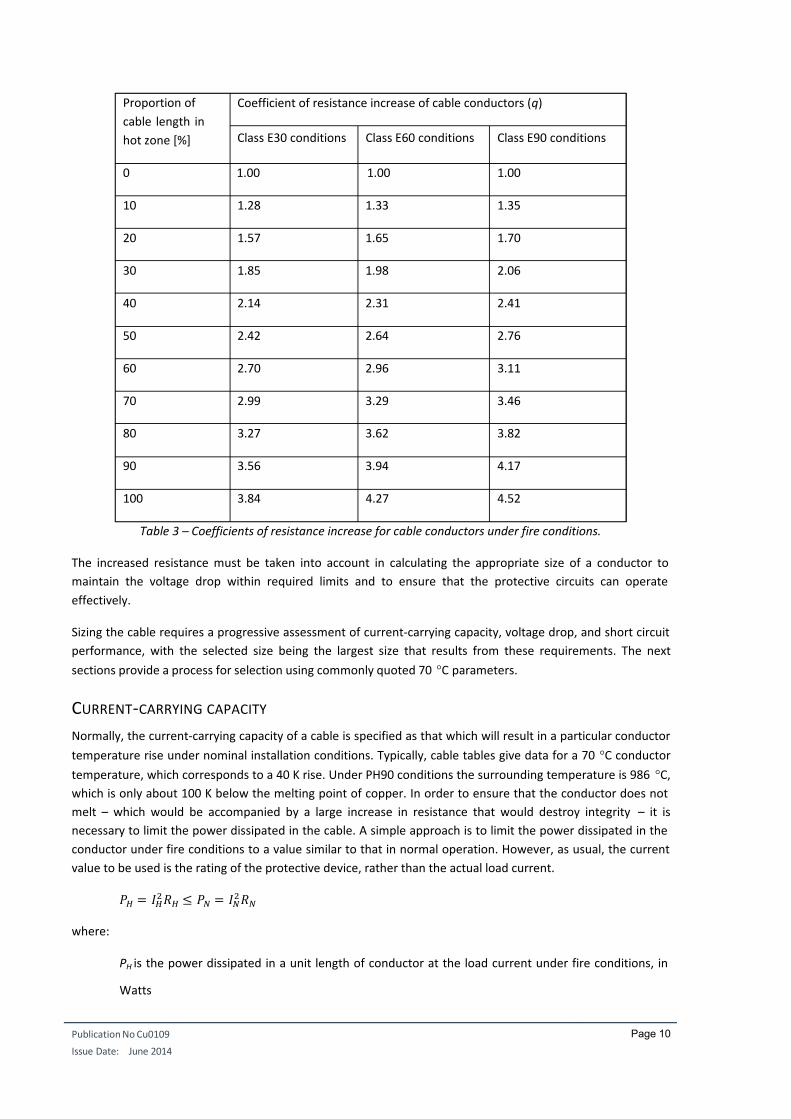
Proportion of
cable length in
hot zone [%]
Coefficient of resistance increase of cable conductors (q)
Class E30 conditions Class E60 conditions Class E90 conditions
0 1.00 1.00 1.00
10 1.28 1.33 1.35
20 1.57 1.65 1.70
30 1.85 1.98 2.06
40 2.14 2.31 2.41
50 2.42 2.64 2.76
60 2.70 2.96 3.11
70 2.99 3.29 3.46
80 3.27 3.62 3.82
90 3.56 3.94 4.17
100 3.84 4.27 4.52
Table 3 – Coefficients of resistance increase for cable conductors under fire conditions.
The increased resistance must be taken into account in calculating the appropriate size of a conductor to
maintain the voltage drop within required limits and to ensure that the protective circuits can operate
effectively.
Sizing the cable requires a progressive assessment of current-carrying capacity, voltage drop, and short circuit
performance, with the selected size being the largest size that results from these requirements. The next
sections provide a process for selection using commonly quoted 70 C parameters.
CURRENT-CARRYING CAPACITY
Normally, the current-carrying capacity of a cable is specified as that which will result in a particular conductor
temperature rise under nominal installation conditions. Typically, cable tables give data for a 70 C conductor
temperature, which corresponds to a 40 K rise. Under PH90 conditions the surrounding temperature is 986 C,
which is only about 100 K below the melting point of copper. In order to ensure that the conductor does not
melt – which would be accompanied by a large increase in resistance that would destroy integrity – it is
necessary to limit the power dissipated in the cable. A simple approach is to limit the power dissipated in the
conductor under fire conditions to a value similar to that in normal operation. However, as usual, the current
value to be used is the rating of the protective device, rather than the actual load current.
= ≤ =
where:
PH is the power dissipated in a unit length of conductor at the load current under fire conditions, in
Watts

7/25/2019 Cu0109 - Fire Cable Sizing - V2
http://slidepdf.com/reader/full/cu0109-fire-cable-sizing-v2 14/20
Publication No Cu0109
Issue Date: June 2014
Page 11
IH is the nominal rating of the protective device, in Amps
RH is the resistance of a unit length of conductor under fire conditions, in
PN is the power dissipated in a unit length of conductor for a conductor temperature of 70 C
IN is the normal rated current of the conductor at 70 C
RN is the resistance of a unit length of conductor at 70 C.
Hence,
≤
=
≤ √
The current carrying capacity, quoted for the cable for normal duty in embedded conduit, must therefore be
m times the current carrying capacity required under fire conditions.
As an example, a cable is required to carry 10 A under PH90 conditions. The protective device is rated at 16 A,
so the cable must have a current carrying capacity, at 70 C conductor temperature, of m times 16 A, this is
16 * 2.12 = 34 A. As a result, a 10 mm2 conductor might be chosen.
CIRCUIT PROTECTION
The protection of fire safety circuits is similar to that for other circuits – automatic disconnection of supply
within the required maximum time as specified in standard IEC 60364, Part 41 or in local derivatives.
Residual Current Circuit Breakers (RCCB) should not be used for protection of fire safety circuits because of the
high reliability requirements of the functions served. At the high temperatures involved, leakage currents
between live conductors and from live conductors to earth increase due to ionisation of the insulation leading
to uncontrolled tripping of RCCBs and loss of safety.
Because it is recommended that fire safety cables are installed in single un-jointed lengths, it follows that each
circuit will be separate with a dedicated protective device at the origin. Obviously, it is essential that this
distribution panel is in a secure location where the risk of being affected by fire is minimised as far as possible.
7/25/2019 Cu0109 - Fire Cable Sizing - V2
http://slidepdf.com/reader/full/cu0109-fire-cable-sizing-v2 15/20
Publication No Cu0109
Issue Date: June 2014
Page 12
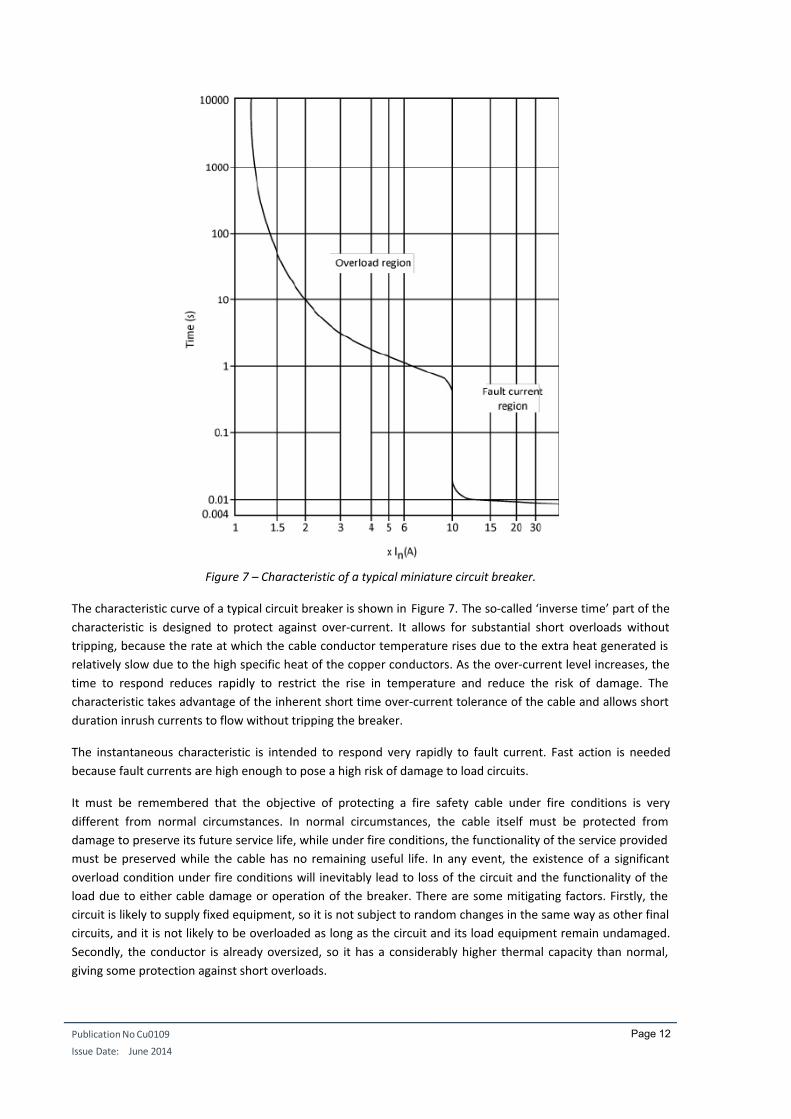
Figure 7 – Characteristic of a typical miniature circuit breaker.
The characteristic curve of a typical circuit breaker is shown in Figure 7. The so-called ‘inverse time’ part of the
characteristic is designed to protect against over-current. It allows for substantial short overloads without
tripping, because the rate at which the cable conductor temperature rises due to the extra heat generated is
relatively slow due to the high specific heat of the copper conductors. As the over-current level increases, the
time to respond reduces rapidly to restrict the rise in temperature and reduce the risk of damage. The
characteristic takes advantage of the inherent short time over-current tolerance of the cable and allows short
duration inrush currents to flow without tripping the breaker.
The instantaneous characteristic is intended to respond very rapidly to fault current. Fast action is needed
because fault currents are high enough to pose a high risk of damage to load circuits.
It must be remembered that the objective of protecting a fire safety cable under fire conditions is very
different from normal circumstances. In normal circumstances, the cable itself must be protected from
damage to preserve its future service life, while under fire conditions, the functionality of the service provided
must be preserved while the cable has no remaining useful life. In any event, the existence of a significant
overload condition under fire conditions will inevitably lead to loss of the circuit and the functionality of the
load due to either cable damage or operation of the breaker. There are some mitigating factors. Firstly, the
circuit is likely to supply fixed equipment, so it is not subject to random changes in the same way as other final
circuits, and it is not likely to be overloaded as long as the circuit and its load equipment remain undamaged.
Secondly, the conductor is already oversized, so it has a considerably higher thermal capacity than normal,
giving some protection against short overloads.
7/25/2019 Cu0109 - Fire Cable Sizing - V2
http://slidepdf.com/reader/full/cu0109-fire-cable-sizing-v2 16/20
Publication No Cu0109
Issue Date: June 2014
Page 13
Protection against fault current is very important because a fault may pose a danger to rescue services and
may be the cause of fire spread. Meeting the fault current criterion requires that the loop impedances – both
the line-neutral and line-protective conductor loops – are sufficiently low for the protective device to operate
if a fault should occur at the remote end of the circuit. It must be remembered that the tolerance on the
instantaneous trip current of circuit breakers is rather wide – the actual trip current may be up to twice the
nominal current.
Care should be taken to ensure that the protective device is capable of breaking the prospective short circuit
current at the source. This level is likely to be higher than normally encountered in a final circuit because the
circuit origin is likely to be electrically closer to the point of common coupling to improve resilience.
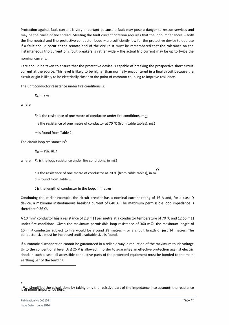
The unit conductor resistance under fire conditions is:
ℎ =
where
Rh is the resistance of one metre of conductor under fire conditions, m
r is the resistance of one metre of conductor at 70 °C (from cable tables), m
m is found from Table 2.
The circuit loop resistance is3:
=
where RH is the loop resistance under fire conditions, in m
r is the resistance of one metre of conductor at 70 °C (from cable tables), in m
q is found from Table 3
L is the length of conductor in the loop, in metres.
Continuing the earlier example, the circuit breaker has a nominal current rating of 16 A and, for a class D
device, a maximum instantaneous breaking current of 640 A. The maximum permissible loop impedance is
therefore 0.36 .
A 10 mm2 conductor has a resistance of 2.8 m per metre at a conductor temperature of 70 °C and 12.66 m
under fire conditions. Given the maximum permissible loop resistance of 360 m, the maximum length of
10 mm2 conductor subject to fire would be around 28 metres – or a circuit length of just 14 metres. Theconductor size must be increased until a suitable size is found.
If automatic disconnection cannot be guaranteed in a reliable way, a reduction of the maximum touch voltage
UT to the conventional level UL ≤ 25 V is allowed. In order to guarantee an effective protection against electric
shock in such a case, all accessible conductive parts of the protected equipment must be bonded to the main
earthing bar of the building.
3
We simplified the calculations by taking only the resistive part of the impedance into account; the reactanceis of minor importance here.

7/25/2019 Cu0109 - Fire Cable Sizing - V2
http://slidepdf.com/reader/full/cu0109-fire-cable-sizing-v2 17/20
Publication No Cu0109
Issue Date: June 2014
Page 14
The required cross-section S PE of the protective conductor is:
L
pa
PE U
k l I S
where:
l is the length of the protective conductor that connects the equipment to the main earthing bar [m]
Ia is the current that trips the protection of the feeder circuit of the equipment [A]
is the conductivity of the protective conductor [1/.m]
k p is the ratio of the protective conductor resistance to R20
UL is the conventional touch voltage limit, i.e. 25 V.
VOLTAGE DROP
Because of the importance of voltage stability to the proper working of any electrical or electronic device, the
voltage drop between the incoming supply at the point of common coupling and the terminals of the end-use
equipment should be limited to 5% under normal conditions and 10% under emergency conditions.
If the protection conditions mentioned above have been met, it is almost certain that the voltage drop
requirement has also been met. If the short circuit current under fire and fault conditions would be > 20 times
the load current, then the voltage drop under fire conditions would be less than 5%. In case of doubt, the
voltage drop can be calculated from the circuit loop impedance (see page 12).
However, there are two very important and related considerations:
Some equipment, such as fire pumps, may be brought into use some time after the fire has
developed. Equipment of this type often requires very large starting currents and these must be taken
into account if the equipment is to be available for use when required.
A fire safety circuit may supply a number of co-located items of equipment. In that case it is necessary
to examine the effects of starting a heavy load on the performance of items already running. Some
quite simple devices, such as electromagnetic contactors, are very sensitive to reduced voltage
operation. If the voltage drop is too high, contactors may release and shut off other vital equipment,
adversely affecting the ability to fight the fire, survive in the immediate environment, or make a safe
escape.
MOTOR STARTING CURRENTS
Electrically driven fire pumps present a particular problem because they draw starting currents many times
higher than the running current. The fire safety circuits supplying them must be designed to supply this
starting current under fire conditions.
Squirrel-cage induction motors are normally used in fire pumps drives because of their simple construction
and high reliability. However, their starting currents are normally five to eight times their nominal running
current and the power factor varies with load. Deep-bar or double-cage induction motors have much smaller
starting currents and higher starting torque than normal design squirrel-cage induction motors. In addition,
the power factor of an induction motor is low during low-load starting. Larger motors – above 5.5 kW – are
normally provided with starter systems to reduce the starting current.
7/25/2019 Cu0109 - Fire Cable Sizing - V2
http://slidepdf.com/reader/full/cu0109-fire-cable-sizing-v2 18/20
Publication No Cu0109
Issue Date: June 2014
Page 15
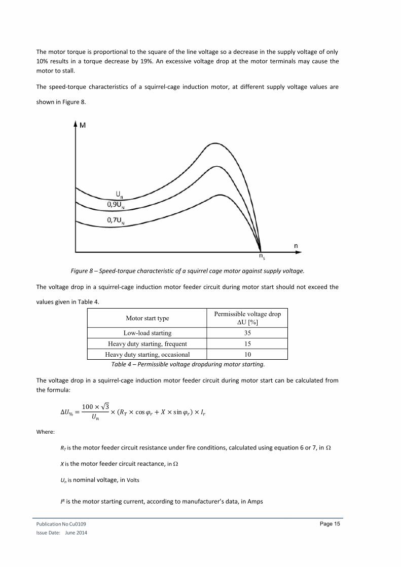
The motor torque is proportional to the square of the line voltage so a decrease in the supply voltage of only
10% results in a torque decrease by 19%. An excessive voltage drop at the motor terminals may cause the
motor to stall.
The speed-torque characteristics of a squirrel-cage induction motor, at different supply voltage values are
shown in Figure 8.
Figure 8 – Speed-torque characteristic of a squirrel cage motor against supply voltage.
The voltage drop in a squirrel-cage induction motor feeder circuit during motor start should not exceed the
values given in Table 4.
Motor start typePermissible voltage drop
U [%]
Low-load starting 35
Heavy duty starting, frequent 15
Heavy duty starting, occasional 10
Table 4 – Permissible voltage dropduring motor starting.
The voltage drop in a squirrel-cage induction motor feeder circuit during motor start can be calculated from
the formula:
∆% = 100 × √ 3
× × cos + × sin ×
Where:
RT is the motor feeder circuit resistance under fire conditions, calculated using equation 6 or 7, in
X is the motor feeder circuit reactance, in
Un is nominal voltage, in Volts
IR is the motor starting current, according to manufacturer’s data, in Amps
7/25/2019 Cu0109 - Fire Cable Sizing - V2
http://slidepdf.com/reader/full/cu0109-fire-cable-sizing-v2 19/20
Publication No Cu0109
Issue Date: June 2014
Page 16
U% is the permissible percentage voltage drop at which starting can be guaranteed, according to
manufacturer’s data
cos r is the power factor of the motor at start-up, according to manufacturer’s data.
Since the power factor of an induction motor is low during start-up, the reactance of the circuit should be
taken into account when calculating voltage drop.
Because of the high starting current and high circuit resistance, it will be necessary to oversize the circuit
conductors appreciably. Methods of reducing the starting current by wye-delta switching or soft starting4
should be considered, although oversizing will still be necessary.
PHYSICAL INSTALLATION
Having selected the appropriate cable, it must be installed using suitable accessories with a similar level of fire
resistance. The manufacturer’s restrictions on bending radius must be strictly observed and the mounting
arrangements should be such that the cable will not sag under fire conditions.
The feeder of the safety services’ switchboard must have a 90 minutes fire resistance, it must be water-
resistant or protected against water, and it must be connected upstream from the fire switch to avoid that it
gets disconnected in case the fire switch is opened.
Note: The increase of the conductors' electrical resistance in case of a fire can be neglected if the cables are
laid inside an approved fire resistant cable duct of which the manufacturer can guarantee that the
temperature inside the duct will not surpass 100°C.
4 ‘ Basics for practical operation Motor starting’, Rockwell Automation,
http://literature.rockwellautomation.com/idc/groups/literature/documents/wp/mot-wp003_-en-p.pdf
7/25/2019 Cu0109 - Fire Cable Sizing - V2
http://slidepdf.com/reader/full/cu0109-fire-cable-sizing-v2 20/20
Publication No Cu0109
I D t J 2014
Page 17
CONCLUSION
Fire safety circuits require a careful design if they are to perform well. The designer must take into account the
increased electrical resistance of the conductors under fire conditions and the consequent effects on current
carrying capacity, voltage drop and short circuit capacity. This paper has discussed how simple multiplication
factors can adapt the standard 70 C parameters for cable sizing and predict performance under fireconditions.