Lv switchgear & lv cable sizing
107
LV Switchgear & LV Cable sizing Asif Eqbal
-
Upload
asif-eqbal -
Category
Engineering
-
view
1.232 -
download
71
Transcript of Lv switchgear & lv cable sizing
LV Switchgear & LV Cable sizingAsif Eqbal
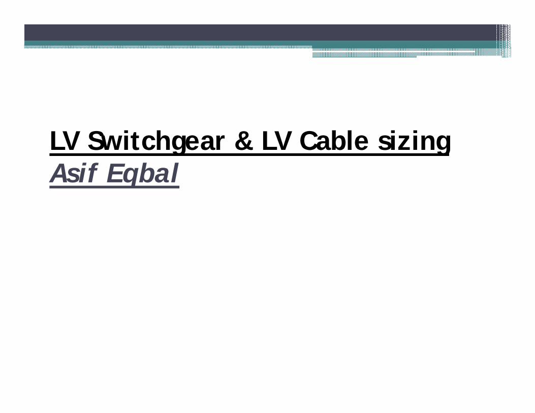
INTRODUCTION• Area of application• Leading manufacturers• Business size of LV Switchgear Industry
LOW VOLTAGE SWITCHGEAR• Governing standards• System parameters• Construction• Busbars and Other components• Wiring and Schematics• Layout aspect & EHS ASPECT
LV CABLE• Sizing criteria
CONTENTS

All Industrial LV load distribution
• LV Motor (up to 200kW) – For pump, grinder, crushers etc…..
• VFD – For application requiring speed control
• Auxiliary & control supply of control & protection equipments
Domestic load distribution- For residential consumers
• Lighting
• Small power
• HVAC
Commercial consumersPrinter & Xerox machine Vending machinesScanner Baggage handling systemElevators and escalators Fire detection and alarm systemPublic address system Illumination
Area of Application
INTRODUCTION
Why use VFD?
LOW VOLTAGE SWITCGEARGoverning standards
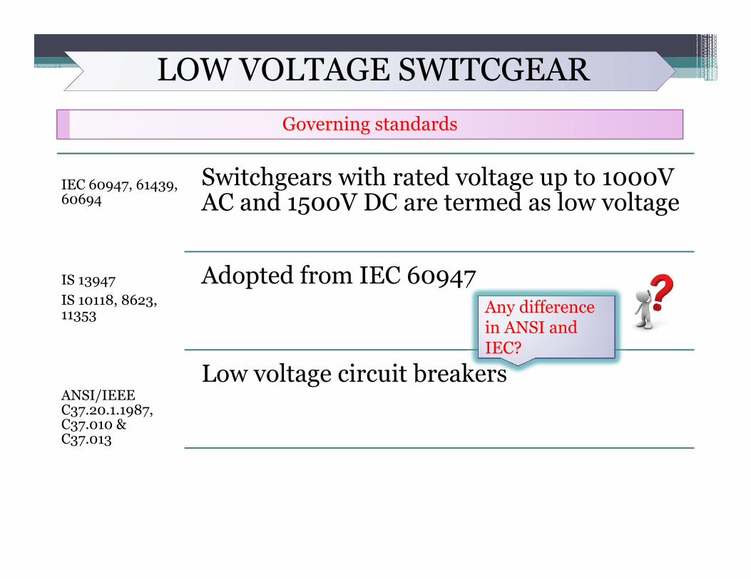
IEC 60947, 61439, 60694
IS 13947IS 10118, 8623, 11353
ANSI/IEEE C37.20.1.1987, C37.010 & C37.013
Switchgears with rated voltage up to 1000V AC and 1500V DC are termed as low voltage
Adopted from IEC 60947
Low voltage circuit breakers
Any difference in ANSI and IEC?
LOW VOLTAGE SWITCGEARDefinitions
Switchgear
PCC & MCC
Metal enclosed & Metal clad
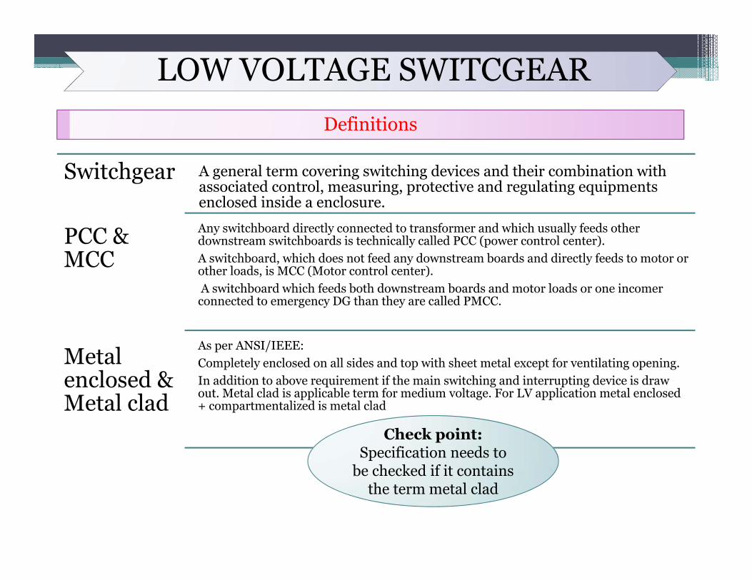
A general term covering switching devices and their combination with associated control, measuring, protective and regulating equipments enclosed inside a enclosure.
Any switchboard directly connected to transformer and which usually feeds other downstream switchboards is technically called PCC (power control center).A switchboard, which does not feed any downstream boards and directly feeds to motor or other loads, is MCC (Motor control center).A switchboard which feeds both downstream boards and motor loads or one incomer connected to emergency DG than they are called PMCC.
As per ANSI/IEEE:Completely enclosed on all sides and top with sheet metal except for ventilating opening.In addition to above requirement if the main switching and interrupting device is draw out. Metal clad is applicable term for medium voltage. For LV application metal enclosed + compartmentalized is metal clad
Check point: Specification needs to
be checked if it contains the term metal clad
LOW VOLTAGE SWITCGEARSystem Parameters
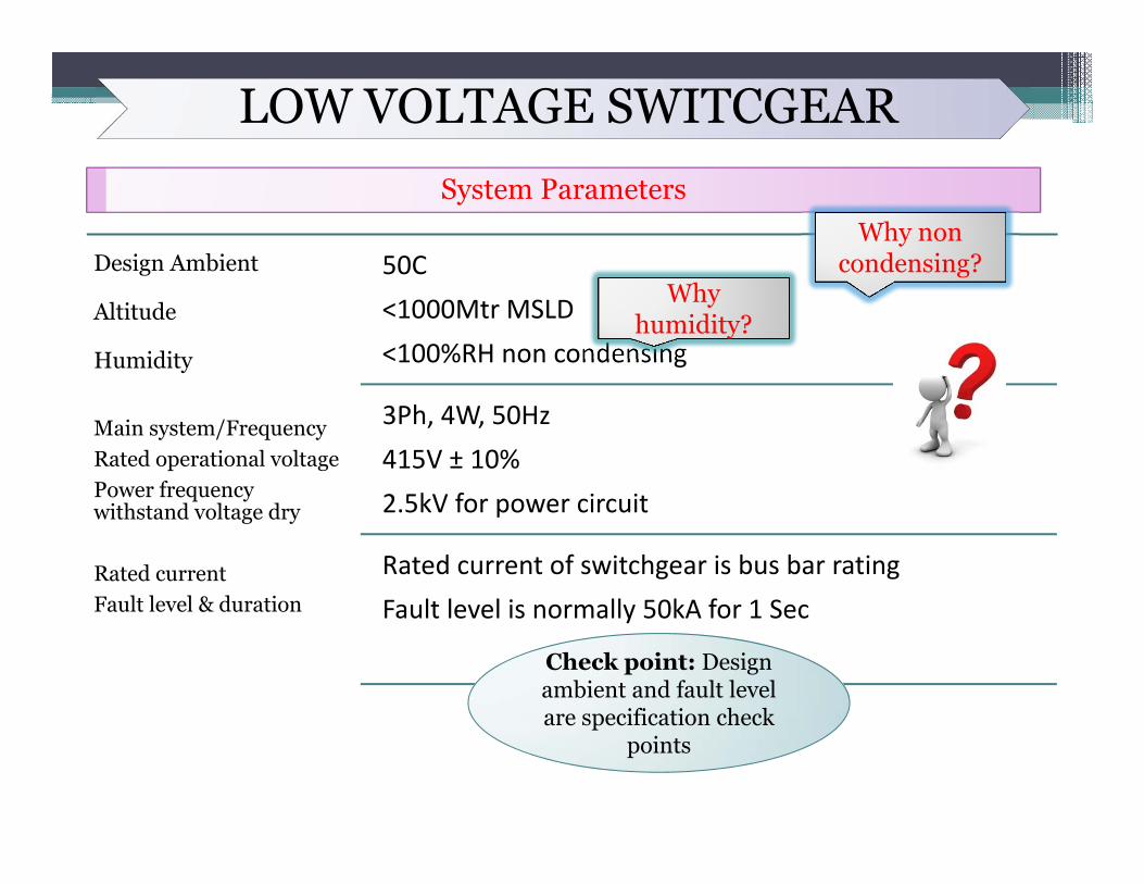
Design Ambient
Altitude
Humidity
Main system/FrequencyRated operational voltagePower frequency withstand voltage dry
Rated currentFault level & duration
50C<1000Mtr MSLD<100%RH non condensing
3Ph, 4W, 50Hz415V ± 10%2.5kV for power circuit
Rated current of switchgear is bus bar ratingFault level is normally 50kA for 1 Sec
humidity?Why
humidity?
Why non condensing?
Check point: Design ambient and fault level are specification check
points
LOW VOLTAGE SWITCGEARConstruction
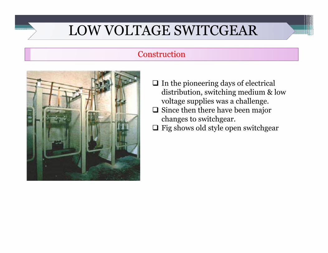
In the pioneering days of electrical distribution, switching medium & low voltage supplies was a challenge.
Since then there have been major changes to switchgear.
Fig shows old style open switchgear
LOW VOLTAGE SWITCGEARConstruction
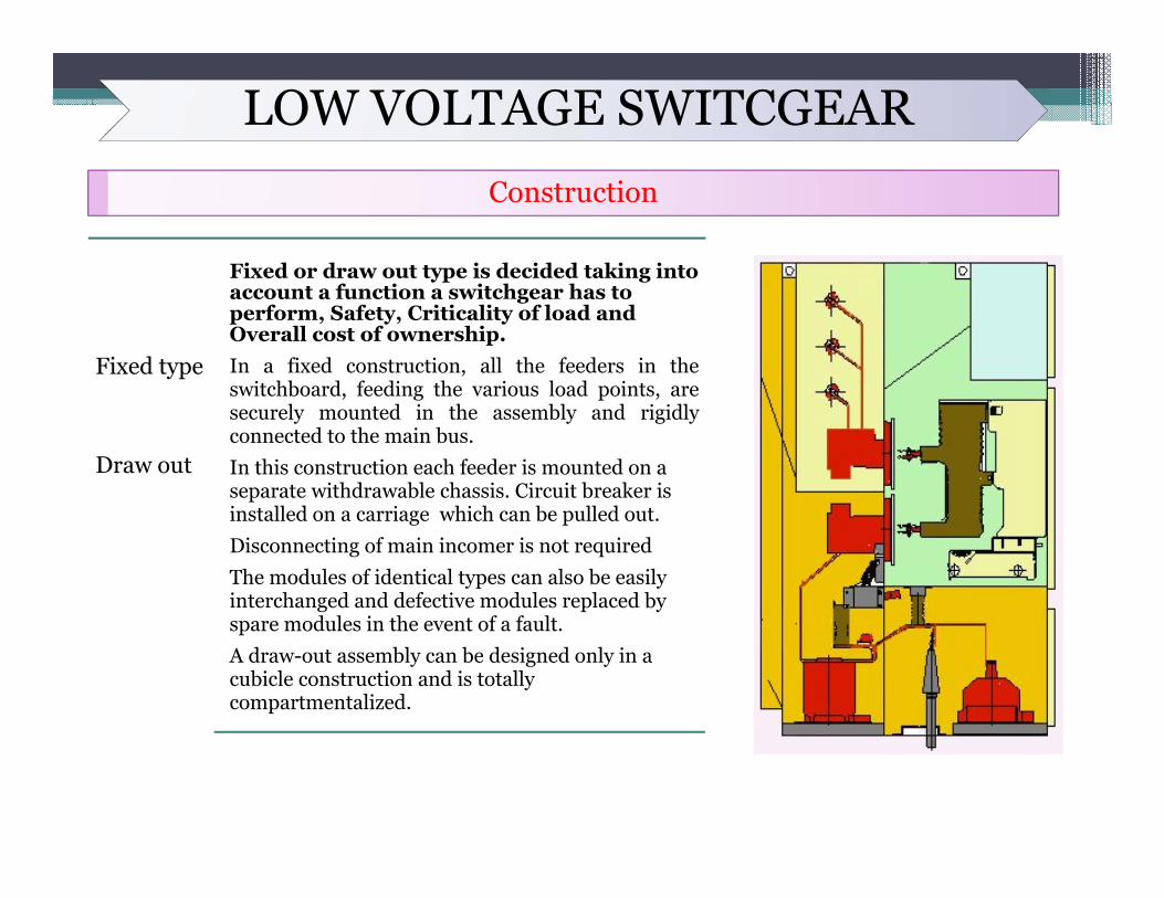
Fixed type
Draw out
Fixed or draw out type is decided taking into account a function a switchgear has to perform, Safety, Criticality of load and Overall cost of ownership.In a fixed construction, all the feeders in theswitchboard, feeding the various load points, aresecurely mounted in the assembly and rigidlyconnected to the main bus.In this construction each feeder is mounted on a separate withdrawable chassis. Circuit breaker is installed on a carriage which can be pulled out.Disconnecting of main incomer is not requiredThe modules of identical types can also be easily interchanged and defective modules replaced by spare modules in the event of a fault.A draw-out assembly can be designed only in a cubicle construction and is totally compartmentalized.
LOW VOLTAGE SWITCGEARConstruction
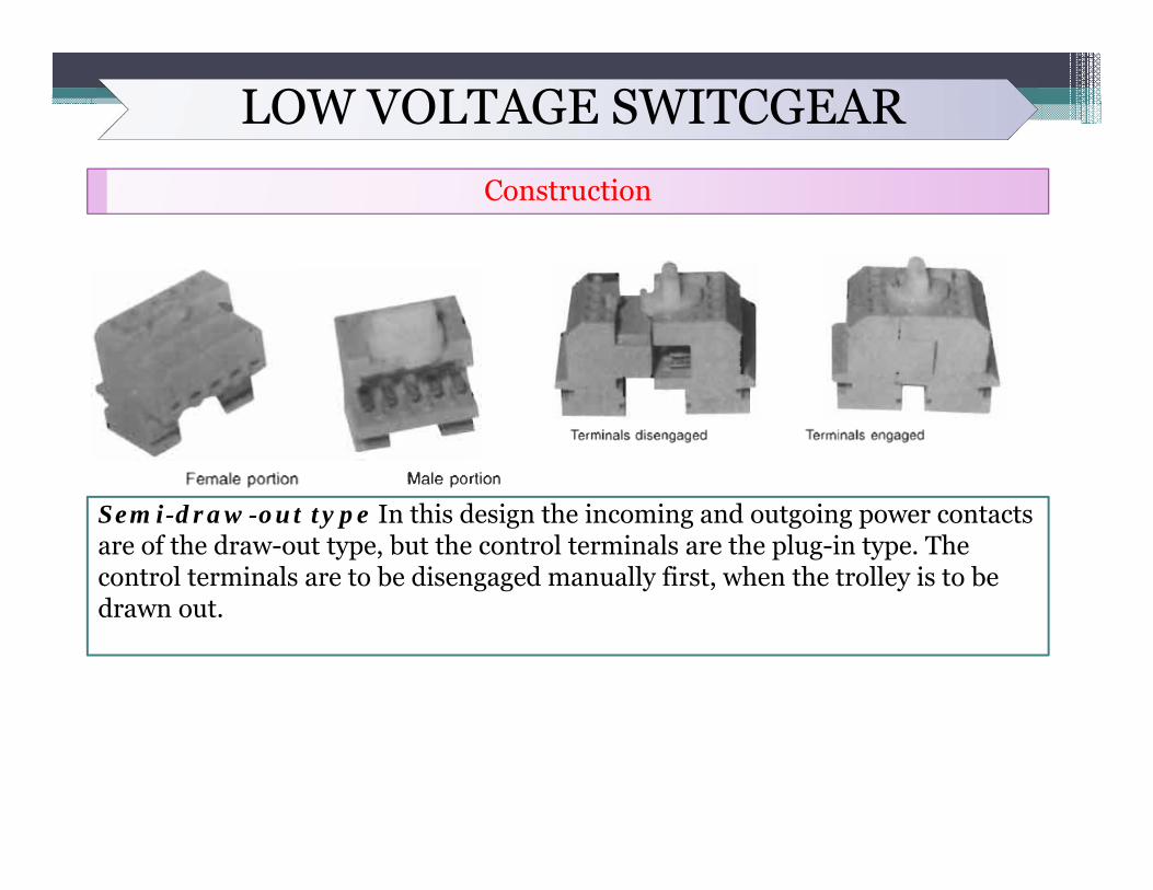
Semi-draw-out type In this design the incoming and outgoing power contacts are of the draw-out type, but the control terminals are the plug-in type. The control terminals are to be disengaged manually first, when the trolley is to be drawn out.
LOW VOLTAGE SWITCGEARConstruction
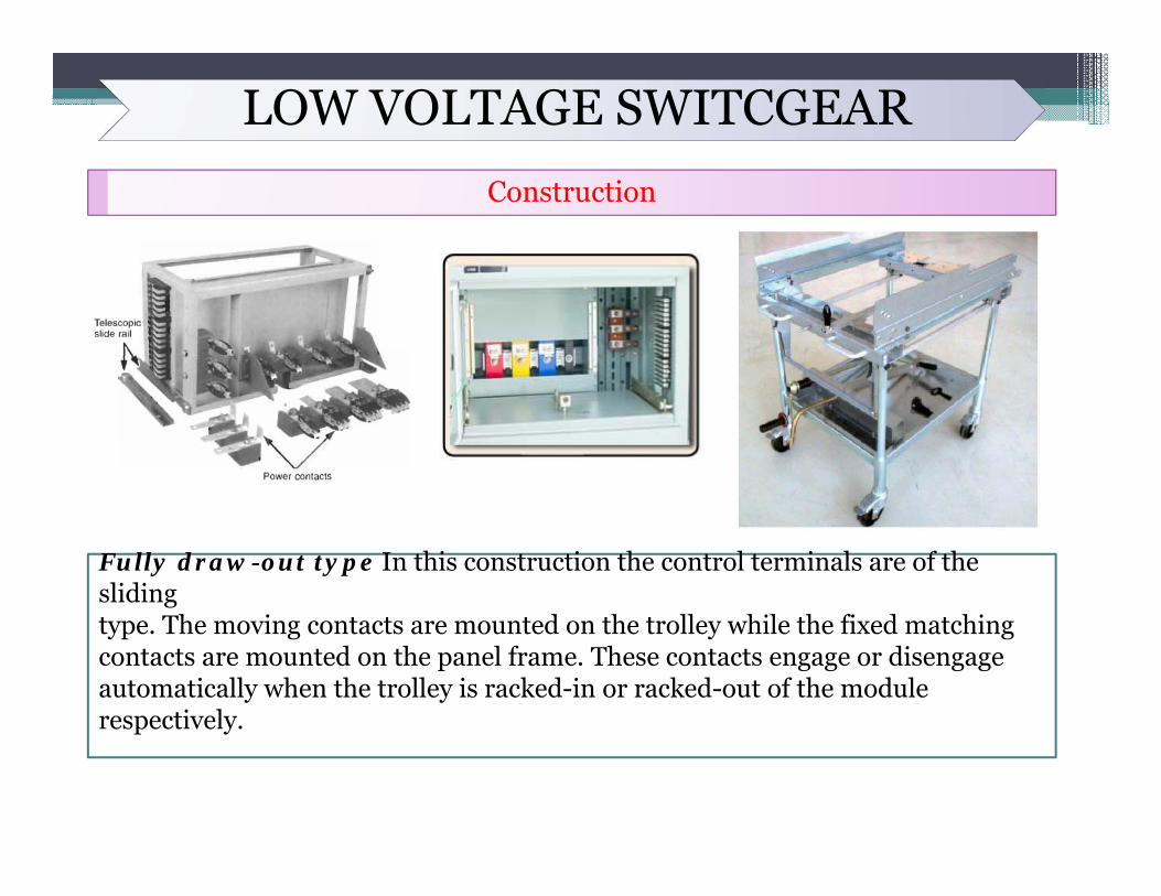
Fully draw-out type In this construction the control terminals are of the slidingtype. The moving contacts are mounted on the trolley while the fixed matching contacts are mounted on the panel frame. These contacts engage or disengage automatically when the trolley is racked-in or racked-out of the module respectively.
LOW VOLTAGE SWITCGEARConstruction
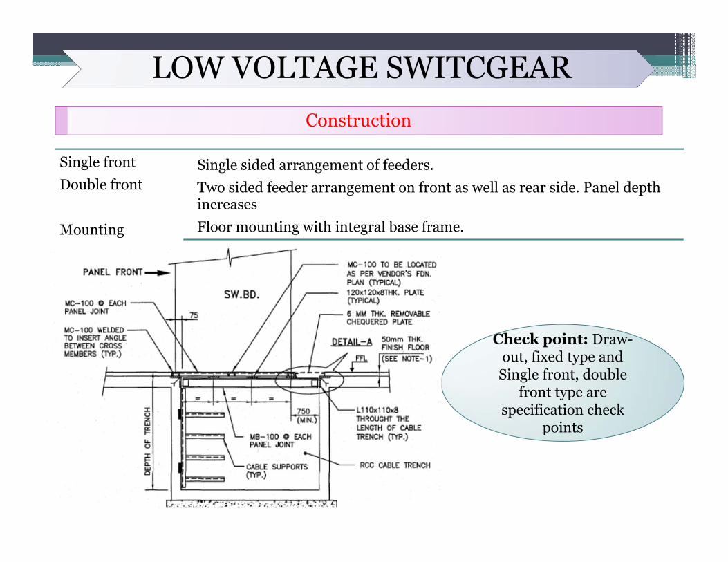
Single frontDouble front
Mounting
Single sided arrangement of feeders.Two sided feeder arrangement on front as well as rear side. Panel depth increasesFloor mounting with integral base frame. ..
Check point: Draw-out, fixed type and
Single front, double front type are
specification check points
LOW VOLTAGE SWITCGEARConstruction
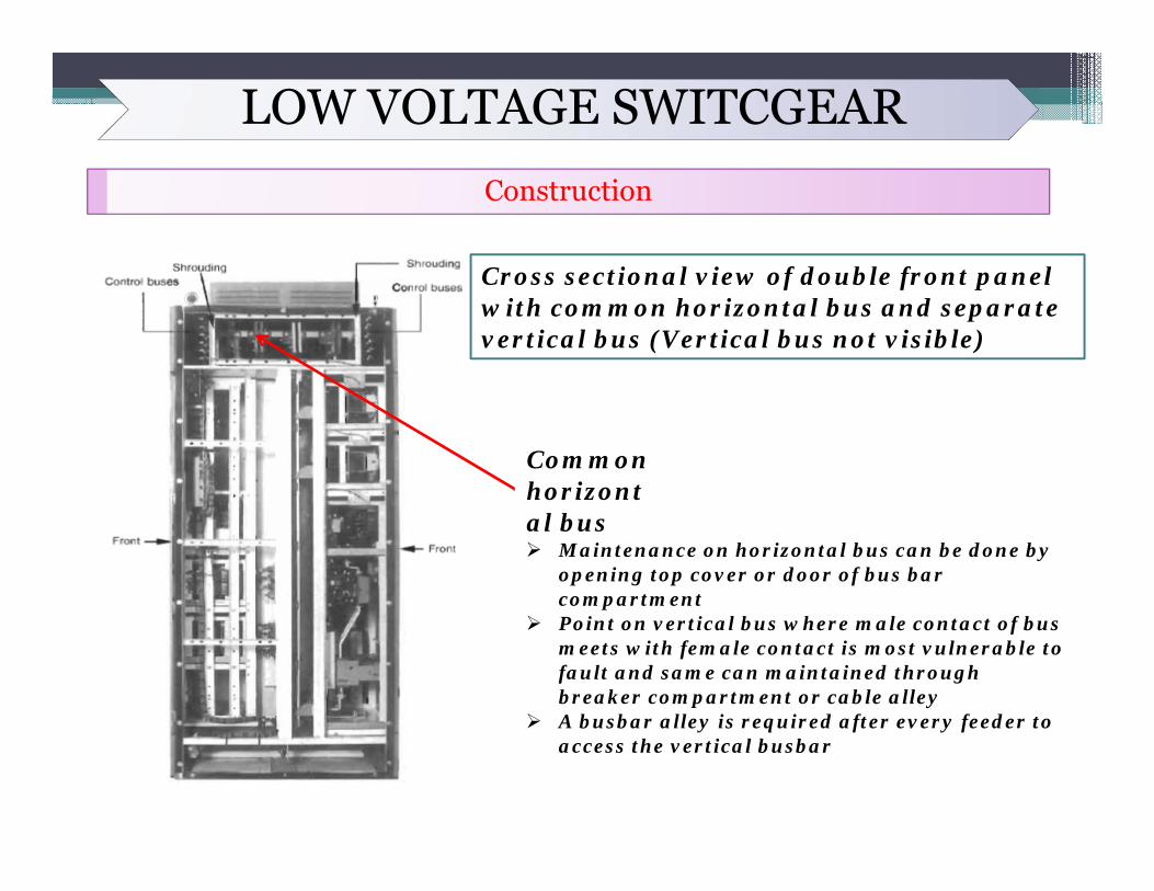
Cross sectional view of double front panel with common horizontal bus and separate vertical bus (Vertical bus not visible)
Common horizontal bus Maintenance on horizontal bus can be done by
opening top cover or door of bus bar compartment
Point on vertical bus where male contact of bus meets with female contact is most vulnerable to fault and same can maintained through breaker compartment or cable alley
A busbar alley is required after every feeder to access the vertical busbar
LOW VOLTAGE SWITCGEARConstruction
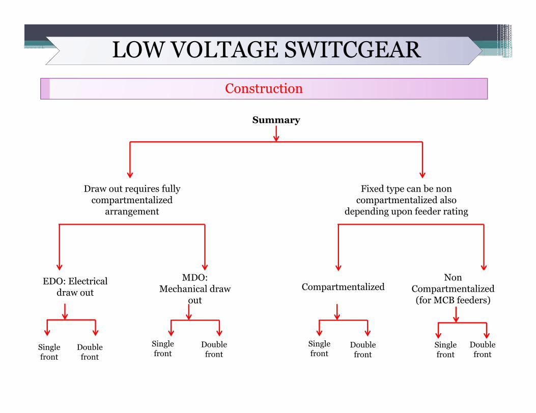
Draw out requires fully compartmentalized
arrangement
EDO: Electrical draw out
MDO: Mechanical draw
out
Fixed type can be non compartmentalized also
depending upon feeder rating
Compartmentalized Non
Compartmentalized (for MCB feeders)
Summary
Single front
Double front
Single front
Double front
Single front
Double front
Single front
Double front
LOW VOLTAGE SWITCGEARConstruction
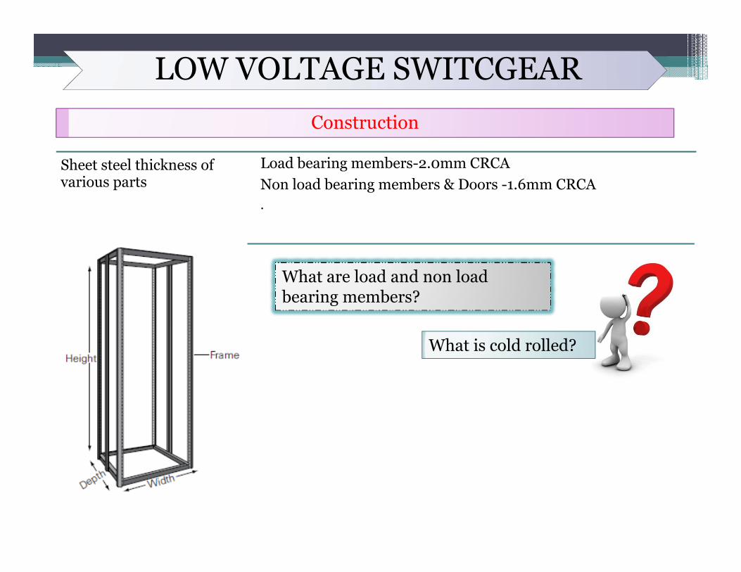
Sheet steel thickness of various parts
Load bearing members-2.0mm CRCANon load bearing members & Doors -1.6mm CRCA.
What are load and non load bearing members?
What is cold rolled?
LOW VOLTAGE SWITCGEARConstruction
Degree of protection
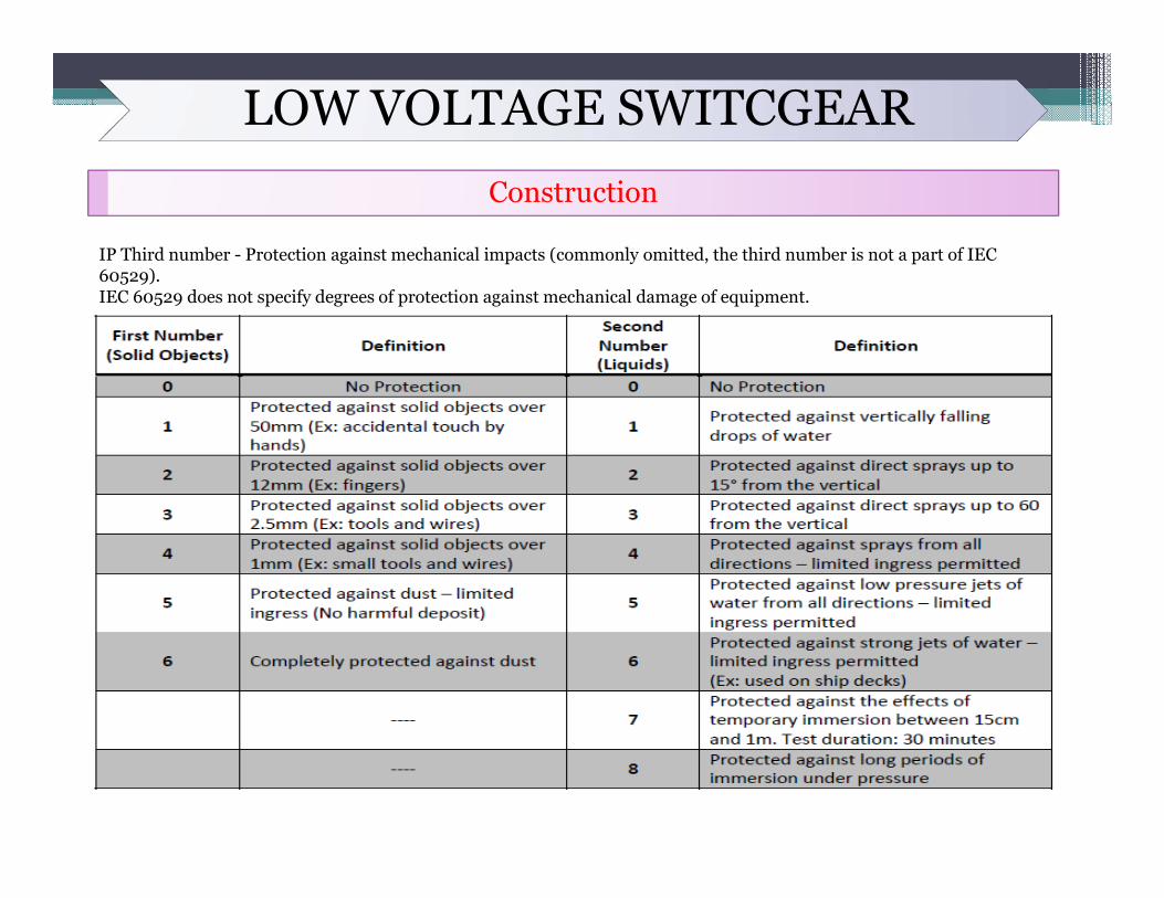
IP-54 < 1600A and IP-42 for ≥ 1600A. Except, switchboard where soft starter panels or APFC capacitor banks are present wherein IP-40 will be applicable.Developed by the European Committee for Electro Technical Standardization (CENELEC) (NEMA IEC 60529 Degrees of Protection Provided by Enclosures - IP Code), specifying the environmental protection the enclosure provides.The IP rating normally has two (or three) numbers:Protection from solid objects or materials Protection from liquids (water) Protection against mechanical impacts (commonly omitted, the third number is not a part of IEC 60529) An "X" can used for one of the digits if there is only one class of protection, i.e. IPX1 which addresses protection against vertically falling drops of water e.g. condensation.
LOW VOLTAGE SWITCGEARConstruction
IP Third number - Protection against mechanical impacts (commonly omitted, the third number is not a part of IEC 60529).IEC 60529 does not specify degrees of protection against mechanical damage of equipment.
LOW VOLTAGE SWITCGEARConstruction
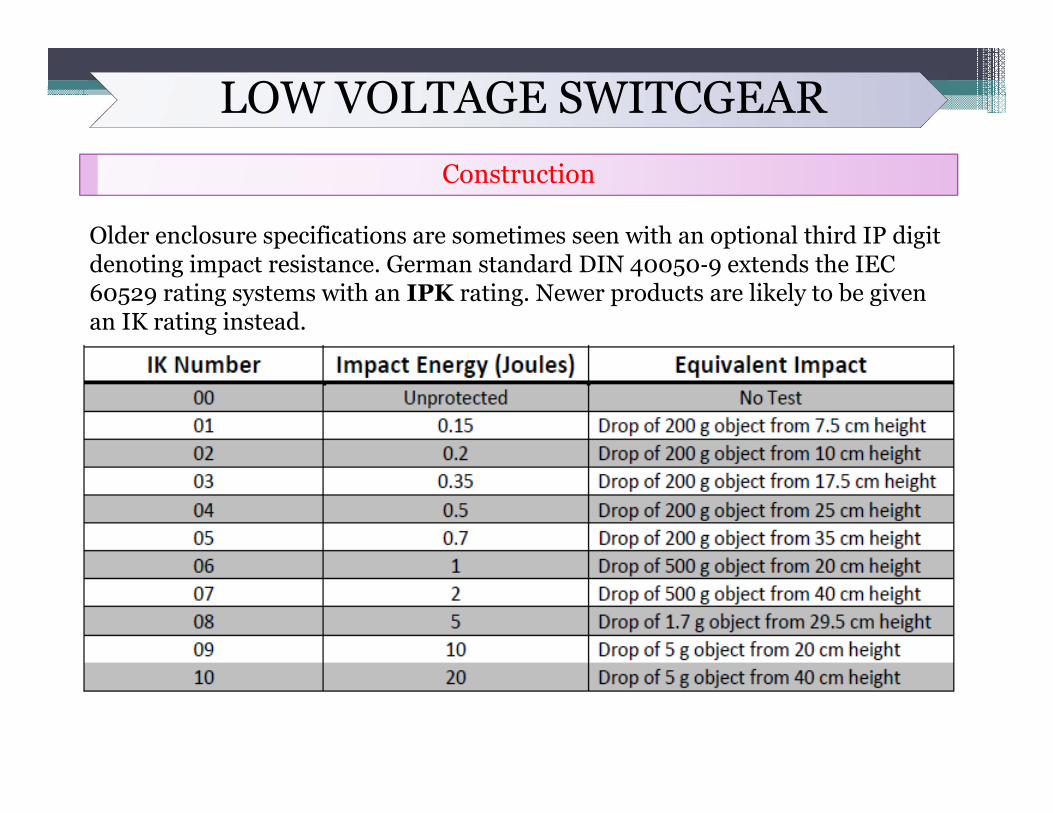
Older enclosure specifications are sometimes seen with an optional third IP digit denoting impact resistance. German standard DIN 40050‐9 extends the IEC 60529 rating systems with an IPK rating. Newer products are likely to be given an IK rating instead.
LOW VOLTAGE SWITCGEARConstruction
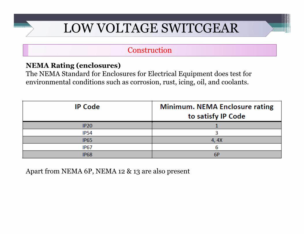
NEMA Rating (enclosures) The NEMA Standard for Enclosures for Electrical Equipment does test for environmental conditions such as corrosion, rust, icing, oil, and coolants.
Apart from NEMA 6P, NEMA 12 & 13 are also present
LOW VOLTAGE SWITCGEARBus bars and other components
Bus bars
NEMA Phase arrangement
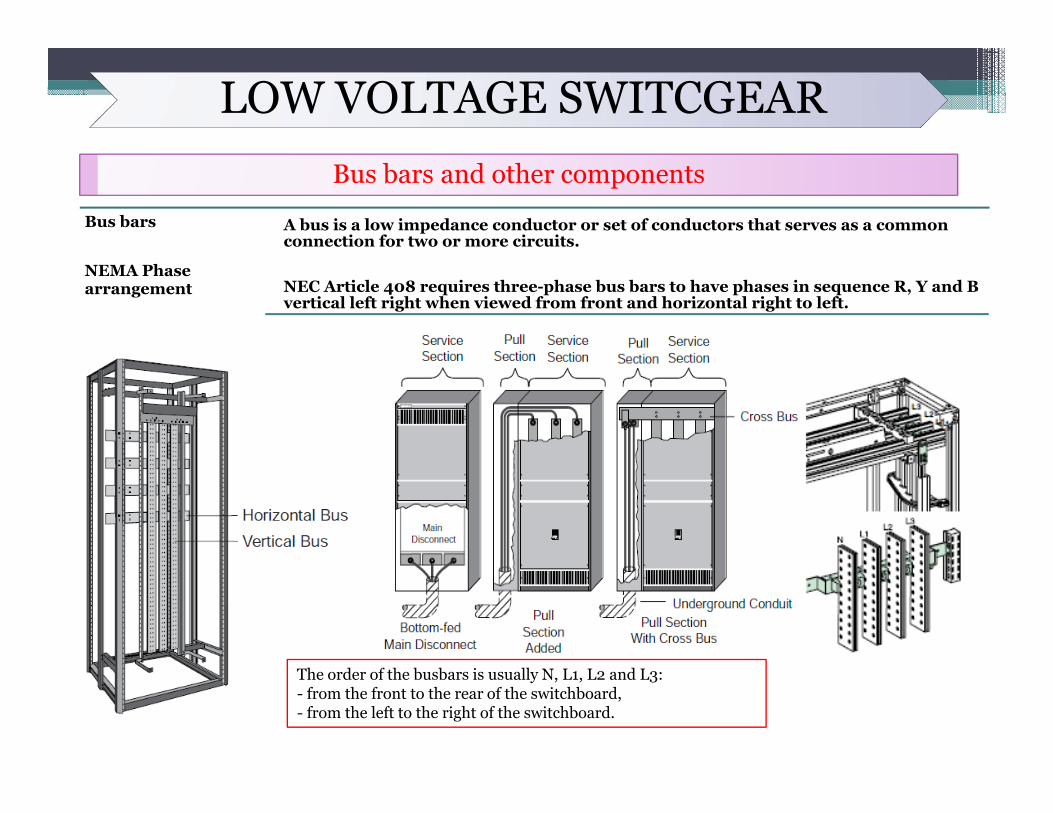
A bus is a low impedance conductor or set of conductors that serves as a common connection for two or more circuits.
NEC Article 408 requires three-phase bus bars to have phases in sequence R, Y and B vertical left right when viewed from front and horizontal right to left.
The order of the busbars is usually N, L1, L2 and L3:- from the front to the rear of the switchboard,- from the left to the right of the switchboard.
LOW VOLTAGE SWITCGEARBus bars and other components
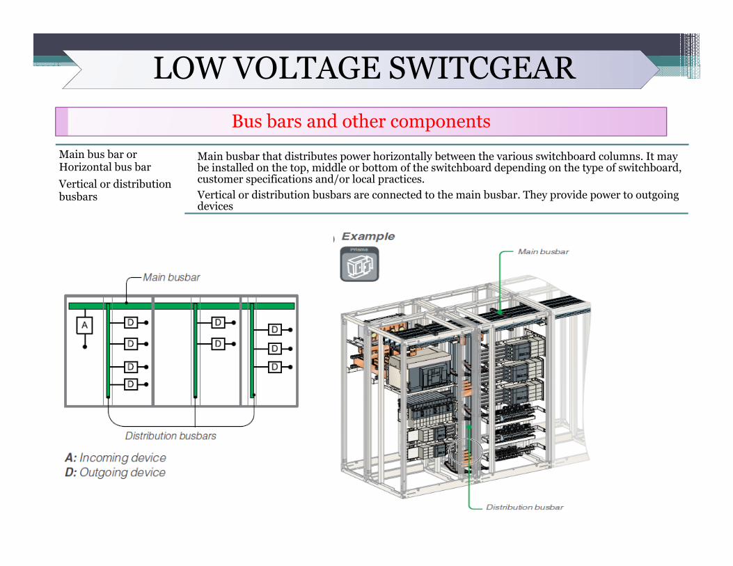
Main bus bar or Horizontal bus barVertical or distribution busbars
Main busbar that distributes power horizontally between the various switchboard columns. It may be installed on the top, middle or bottom of the switchboard depending on the type of switchboard, customer specifications and/or local practices.Vertical or distribution busbars are connected to the main busbar. They provide power to outgoing devices
LOW VOLTAGE SWITCGEARBus bars and other components
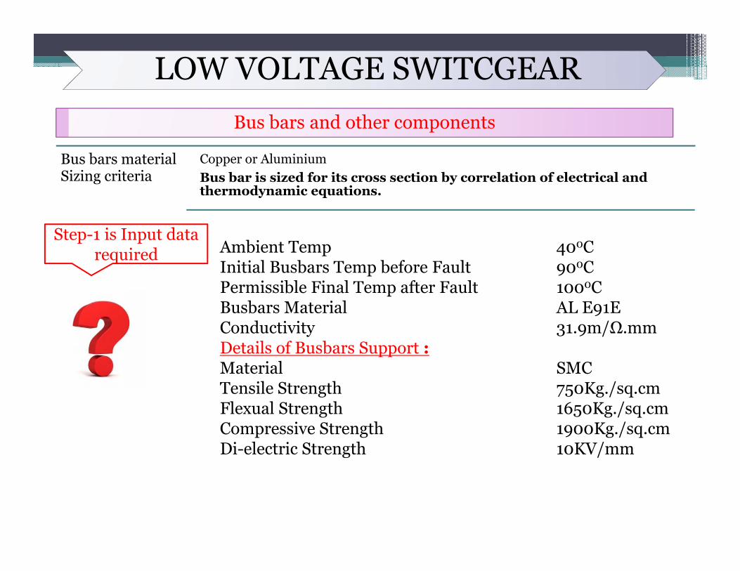
Bus bars material Sizing criteria
Copper or AluminiumBus bar is sized for its cross section by correlation of electrical and thermodynamic equations.
Step-1 is Input data required Ambient Temp 400C
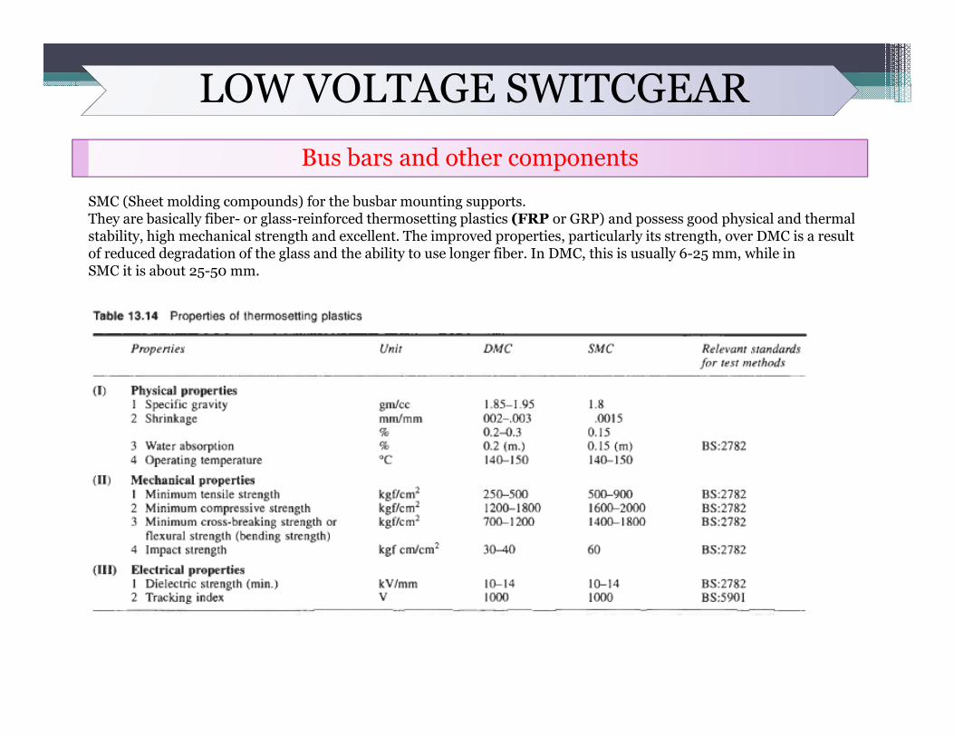
Initial Busbars Temp before Fault 900CPermissible Final Temp after Fault 1000CBusbars Material AL E91EConductivity 31.9m/Ω.mmDetails of Busbars Support :Material SMCTensile Strength 750Kg./sq.cmFlexual Strength 1650Kg./sq.cmCompressive Strength 1900Kg./sq.cmDi-electric Strength 10KV/mm
LOW VOLTAGE SWITCGEARBus bars and other components
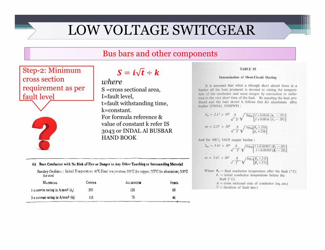
Step-2: Minimum cross section requirement as per fault level
whereS =cross sectional area, I=fault level, t=fault withstanding time, k=constant. For formula reference & value of constant k refer IS 3043 or INDAL Al BUSBAR HAND BOOK
LOW VOLTAGE SWITCGEARBus bars and other components
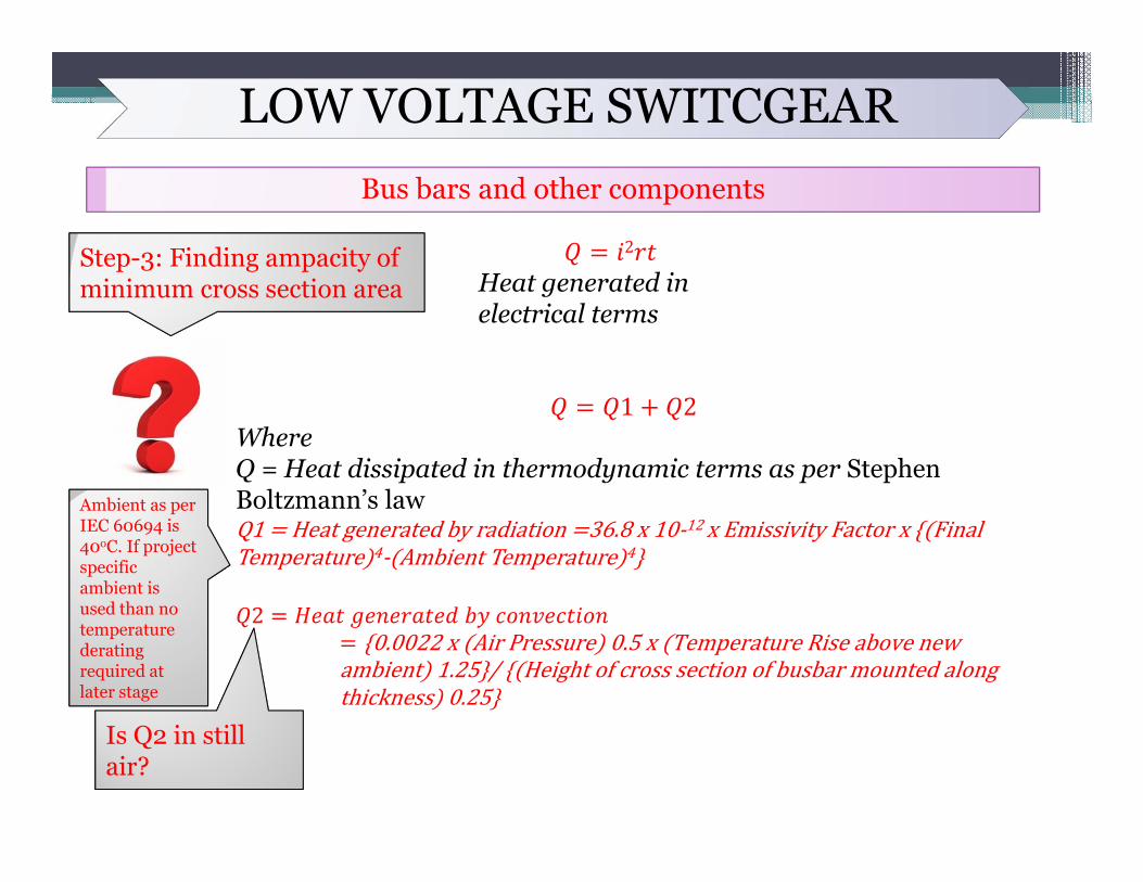
Step-3: Finding ampacity of minimum cross section area
2
Heat generated in electrical terms
1 2WhereQ = Heat dissipated in thermodynamic terms as per Stephen Boltzmann’s lawQ1 Heatgeneratedbyradiation 36.8x10‐12xEmissivityFactorx FinalTemperature 4‐ AmbientTemperature 4
2 0.0022x AirPressure 0.5x TemperatureRiseabovenew
ambient 1.25 / Heightofcrosssectionofbusbarmountedalongthickness 0.25
Is Q2 in still air?
Ambient as per IEC 60694 is 40oC. If project specific ambient is used than no temperature derating required at later stage
LOW VOLTAGE SWITCGEARBus bars and other components
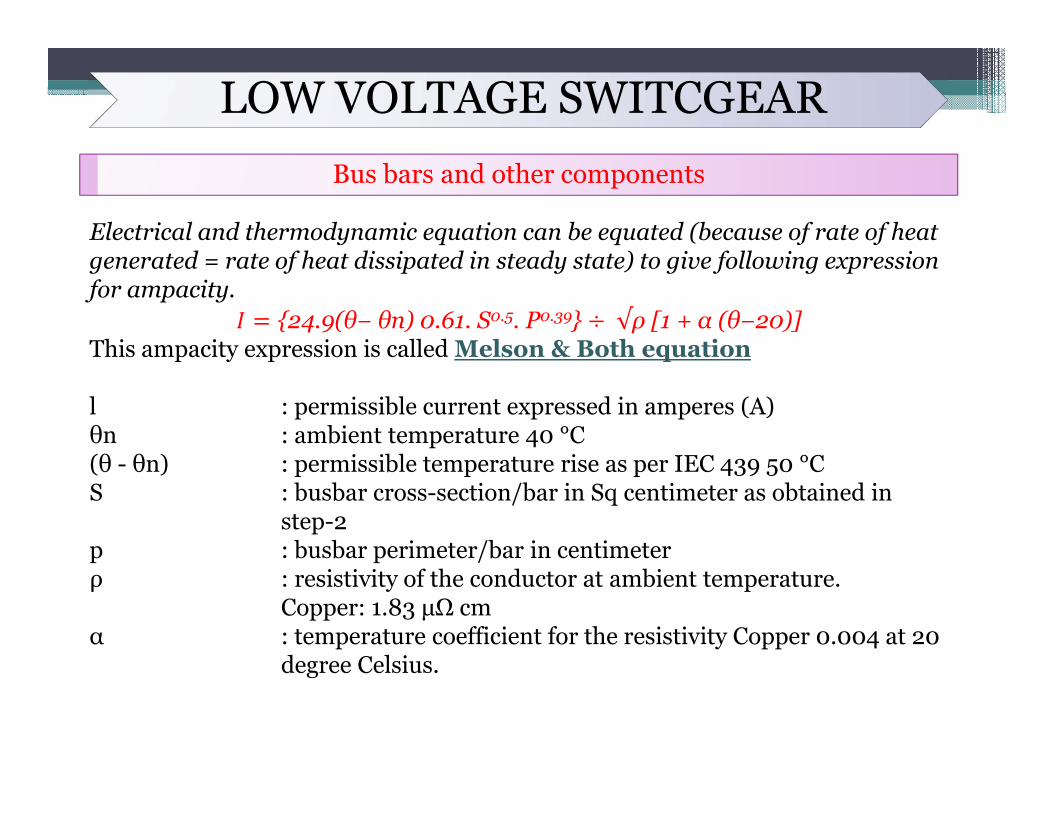
Electrical and thermodynamic equation can be equated (because of rate of heat generated = rate of heat dissipated in steady state) to give following expression for ampacity.
24.9(θ− θn) 0.61. S0.5. P0.39 √ρ [1 + α (θ−20)]This ampacity expression is called Melson & Both equation
l : permissible current expressed in amperes (A)θn : ambient temperature 40 °C(θ - θn) : permissible temperature rise as per IEC 439 50 °CS : busbar cross-section/bar in Sq centimeter as obtained in
step-2p : busbar perimeter/bar in centimeterρ : resistivity of the conductor at ambient temperature.
Copper: 1.83 μΩ cmα : temperature coefficient for the resistivity Copper 0.004 at 20
degree Celsius.
LOW VOLTAGE SWITCGEARBus bars and other components
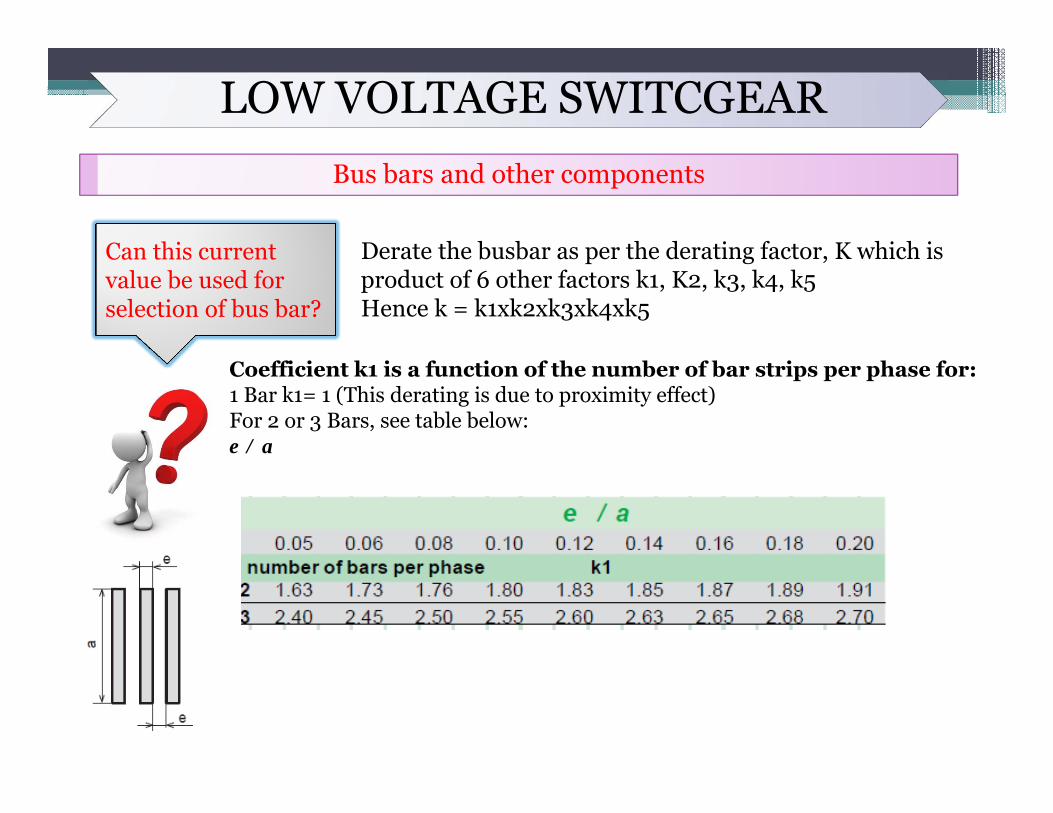
Can this current value be used for selection of bus bar?
Derate the busbar as per the derating factor, K which is product of 6 other factors k1, K2, k3, k4, k5Hence k = k1xk2xk3xk4xk5
Coefficient k1 is a function of the number of bar strips per phase for:1 Bar k1= 1 (This derating is due to proximity effect)For 2 or 3 Bars, see table below:e / a
LOW VOLTAGE SWITCGEARBus bars and other components
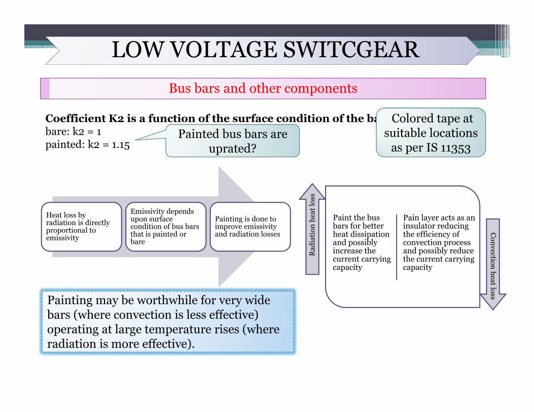
Coefficient K2 is a function of the surface condition of the bars:bare: k2 = 1painted: k2 = 1.15
Painted bus bars are uprated?
Colored tape at suitable locations
as per IS 11353
Heat loss by radiation is directly proportional to emissivity
Emissivity depends upon surface condition of bus bars that is painted or bare
Painting is done to improve emissivity and radiation losses
Paint the bus bars for better heat dissipation and possibly increase the current carrying capacity
Pain layer acts as an insulator reducing the efficiency of convection process and possibly reduce the current carrying capacity
Rad
iati
on h
eat l
oss
Convection heat loss
Painting may be worthwhile for very wide bars (where convection is less effective) operating at large temperature rises (where radiation is more effective).
LOW VOLTAGE SWITCGEARBus bars and other components
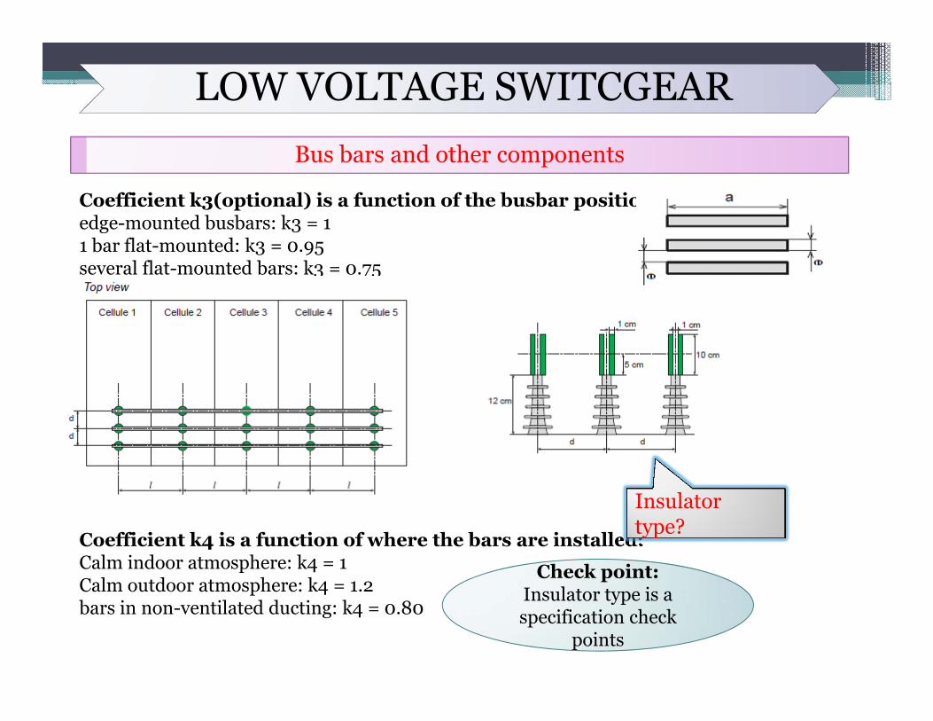
Coefficient k3(optional) is a function of the busbar position: edge-mounted busbars: k3 = 11 bar flat-mounted: k3 = 0.95several flat-mounted bars: k3 = 0.75
Coefficient k4 is a function of where the bars are installed:Calm indoor atmosphere: k4 = 1Calm outdoor atmosphere: k4 = 1.2bars in non-ventilated ducting: k4 = 0.80
ypInsulator type?
Check point: Insulator type is a specification check
points
LOW VOLTAGE SWITCGEARBus bars and other components
SMC (Sheet molding compounds) for the busbar mounting supports. They are basically fiber- or glass-reinforced thermosetting plastics (FRP or GRP) and possess good physical and thermal stability, high mechanical strength and excellent. The improved properties, particularly its strength, over DMC is a resultof reduced degradation of the glass and the ability to use longer fiber. In DMC, this is usually 6-25 mm, while inSMC it is about 25-50 mm.

LOW VOLTAGE SWITCGEARBus bars and other components
Coefficient k5 is a function of the artificial ventilation, busbar area & enclosure area:Enclosure factor = Busbar area/ Enclosure area
LOW VOLTAGE SWITCGEARBus bars and other components
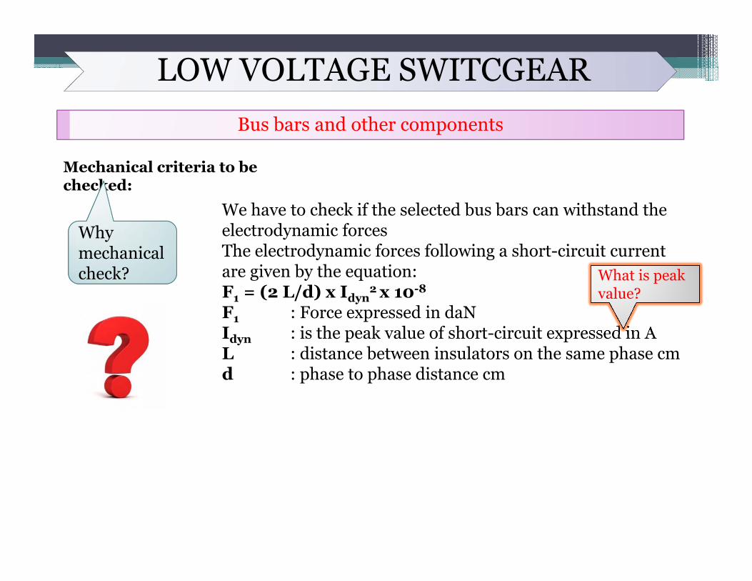
Mechanical criteria to be checked:
Why mechanical check?
We have to check if the selected bus bars can withstand the electrodynamic forcesThe electrodynamic forces following a short-circuit current are given by the equation:F1 = (2 L/d) x Idyn
2 x 10⁻⁸
F1 : Force expressed in daNIdyn : is the peak value of short-circuit expressed in AL : distance between insulators on the same phase cmd : phase to phase distance cm
What is peak value?
LOW VOLTAGE SWITCGEARBus bars and other components
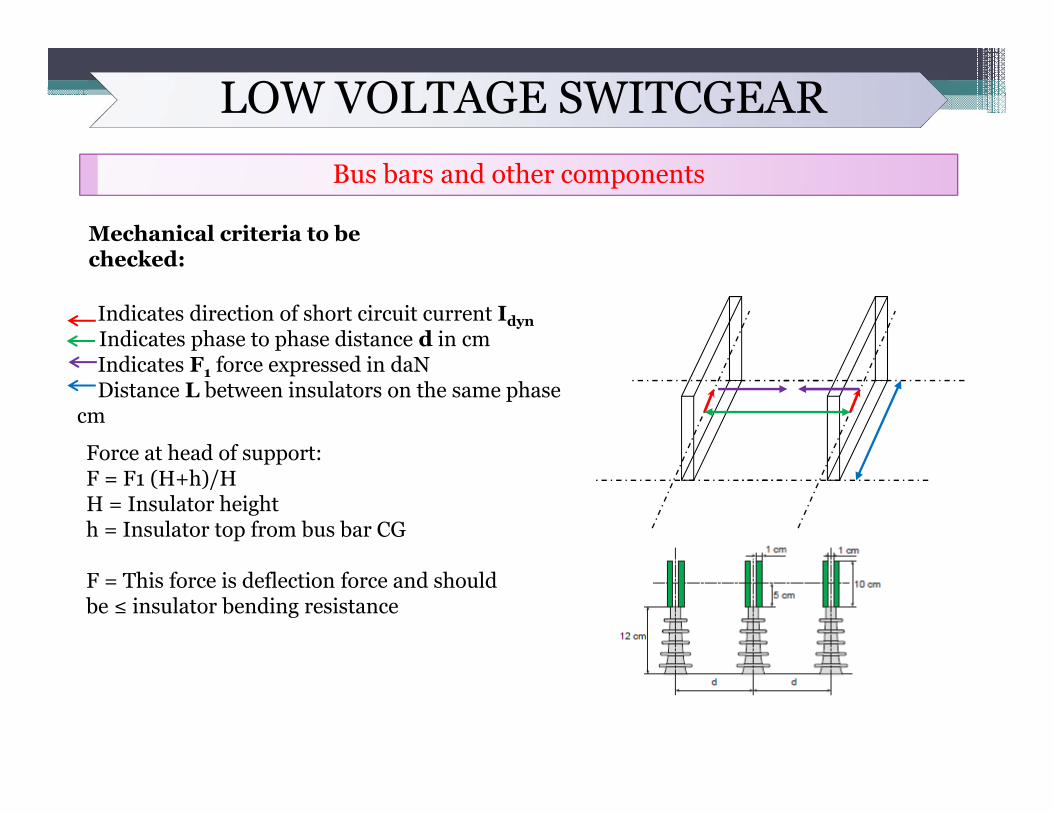
Mechanical criteria to be checked:
Indicates direction of short circuit current IdynIndicates phase to phase distance d in cmIndicates F1 force expressed in daNDistance L between insulators on the same phase
cm
Force at head of support:F = F1 (H+h)/HH = Insulator heighth = Insulator top from bus bar CG
F = This force is deflection force and should be ≤ insulator bending resistance
LOW VOLTAGE SWITCGEARBus bars and other components
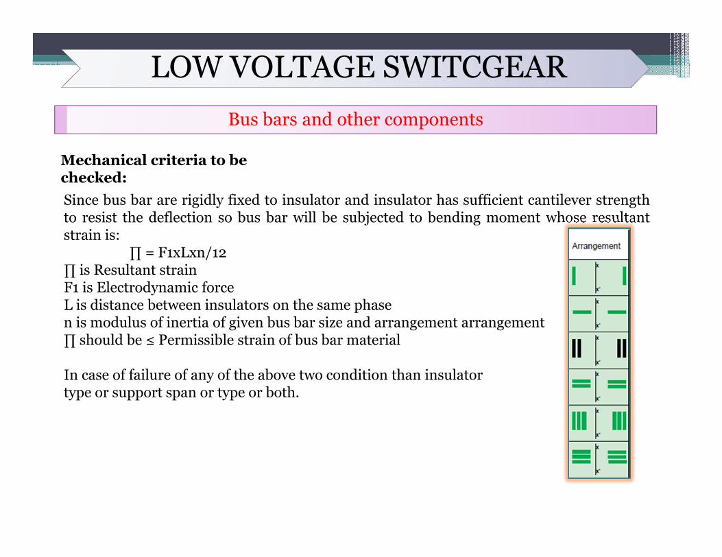
Mechanical criteria to be checked:Since bus bar are rigidly fixed to insulator and insulator has sufficient cantilever strengthto resist the deflection so bus bar will be subjected to bending moment whose resultantstrain is:
∏ = F1xLxn/12∏ is Resultant strainF1 is Electrodynamic forceL is distance between insulators on the same phasen is modulus of inertia of given bus bar size and arrangement arrangement∏ should be ≤ Permissible strain of bus bar material
In case of failure of any of the above two condition than insulatortype or support span or type or both.

LOW VOLTAGE SWITCGEARBus bars and other components
What is current density?What is role of current
density in bus bar sizing?
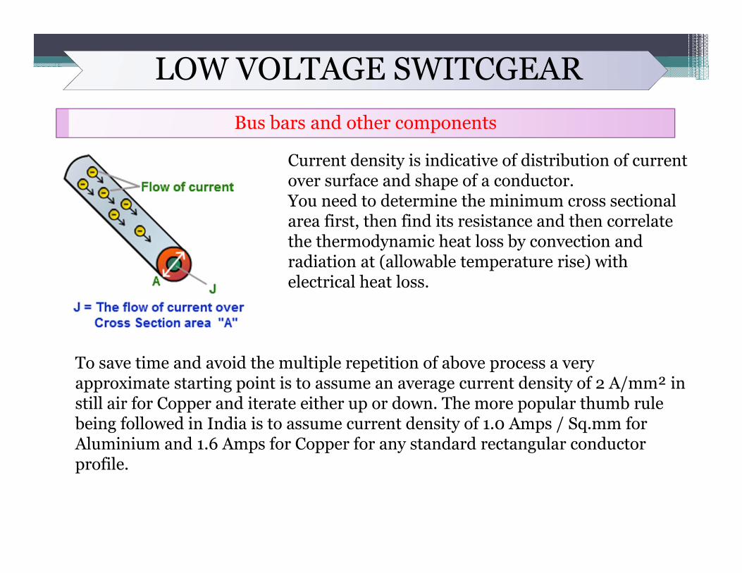
Current density is a measure of the density of an electric current. It is defined as a vector whose magnitude is the electric current per cross-sectional area. In SI units, the current density is measured in amperes per square metrer
LOW VOLTAGE SWITCGEARBus bars and other components
To save time and avoid the multiple repetition of above process a very approximate starting point is to assume an average current density of 2 A/mm² in still air for Copper and iterate either up or down. The more popular thumb rule being followed in India is to assume current density of 1.0 Amps / Sq.mm for Aluminium and 1.6 Amps for Copper for any standard rectangular conductor profile.
Current density is indicative of distribution of current over surface and shape of a conductor.You need to determine the minimum cross sectional area first, then find its resistance and then correlate the thermodynamic heat loss by convection and radiation at (allowable temperature rise) with electrical heat loss.
LOW VOLTAGE SWITCGEARBus bars and other components: Forms of separation inside switchboard
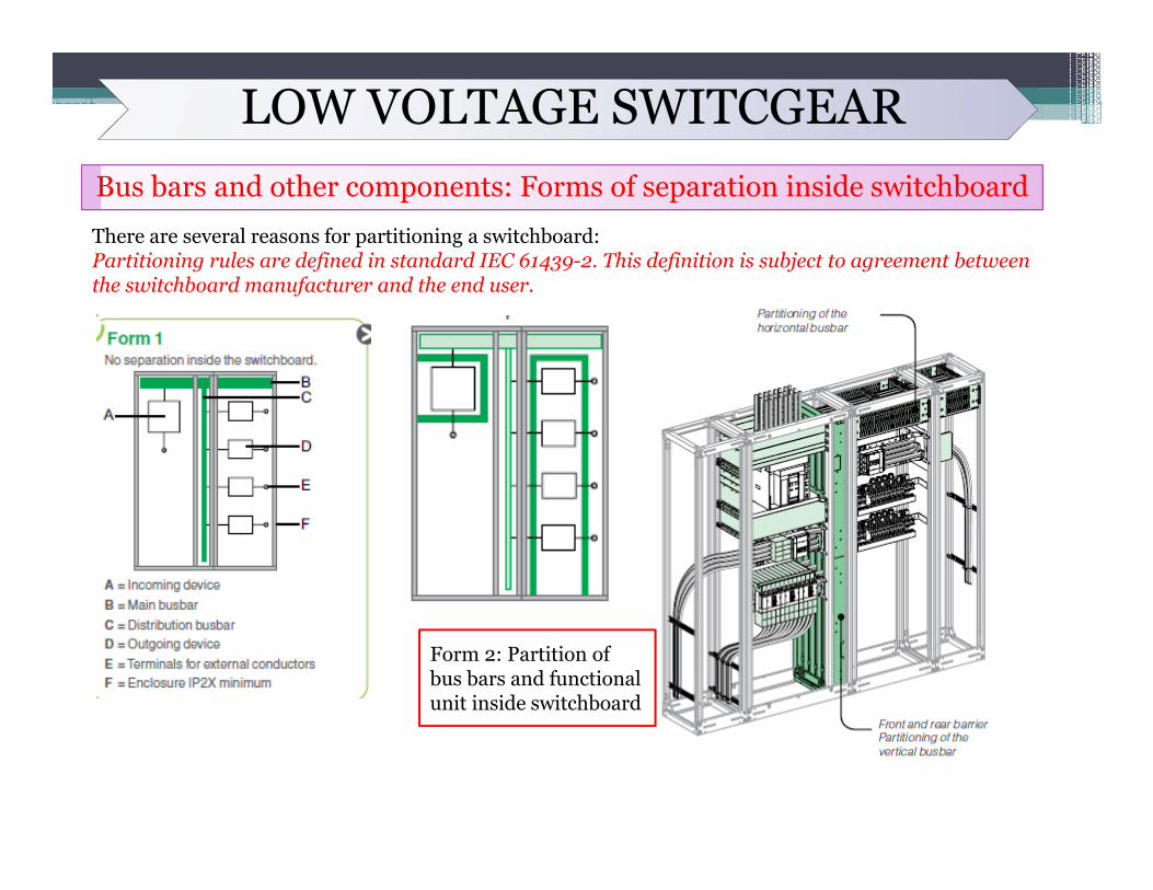
There are several reasons for partitioning a switchboard:Partitioning rules are defined in standard IEC 61439-2. This definition is subject to agreement between the switchboard manufacturer and the end user.
Form 2: Partition of bus bars and functional unit inside switchboard
LOW VOLTAGE SWITCGEARBus bars and other components: Forms of separation inside switchboard
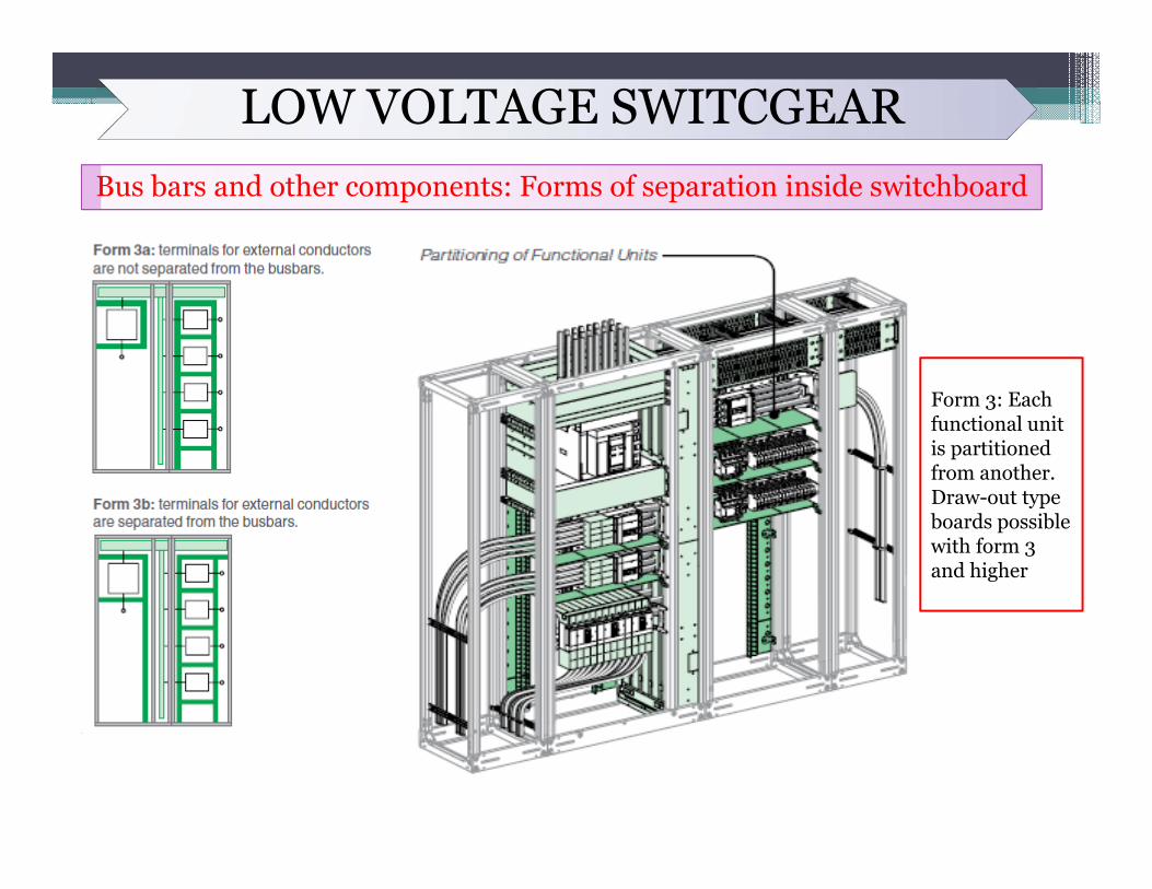
Form 3: Each functional unit is partitioned from another. Draw-out type boards possible with form 3 and higher
LOW VOLTAGE SWITCGEARBus bars and other components: Forms of separation inside switchboard
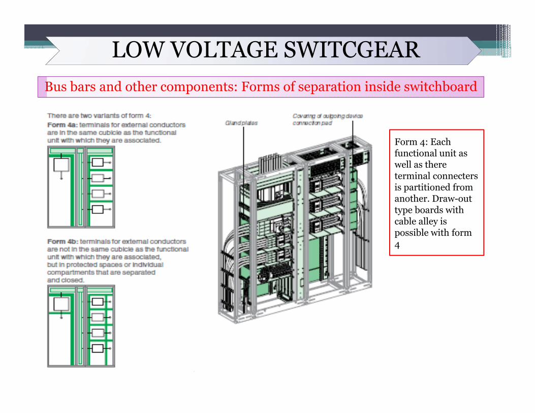
Form 4: Each functional unit as well as there terminal connecters is partitioned from another. Draw-out type boards with cable alley is possible with form 4
LOW VOLTAGE SWITCGEARBus bars and other components: Sleeving or bare
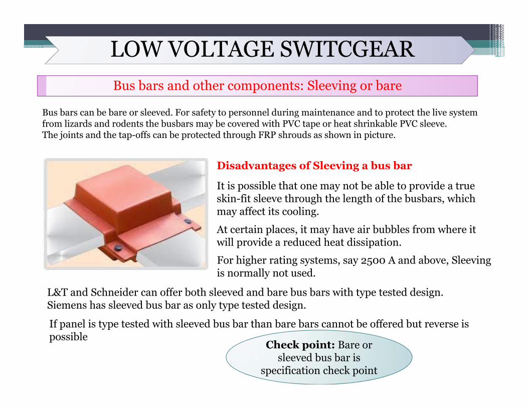
Bus bars can be bare or sleeved. For safety to personnel during maintenance and to protect the live system from lizards and rodents the busbars may be covered with PVC tape or heat shrinkable PVC sleeve.The joints and the tap-offs can be protected through FRP shrouds as shown in picture.
It is possible that one may not be able to provide a true skin-fit sleeve through the length of the busbars, which may affect its cooling.
At certain places, it may have air bubbles from where it will provide a reduced heat dissipation.
Disadvantages of Sleeving a bus bar
For higher rating systems, say 2500 A and above, Sleeving is normally not used.
L&T and Schneider can offer both sleeved and bare bus bars with type tested design. Siemens has sleeved bus bar as only type tested design.
If panel is type tested with sleeved bus bar than bare bars cannot be offered but reverse is possible
Check point: Bare or sleeved bus bar is
specification check point
LOW VOLTAGE SWITCGEARBus bars and other components: ACB, MCCB, MPCB, MCB, ELCB
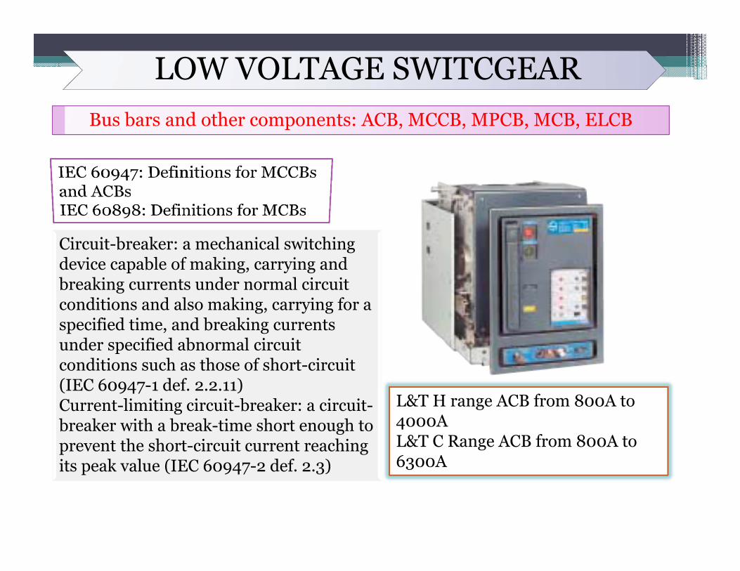
Circuit-breaker: a mechanical switching device capable of making, carrying and breaking currents under normal circuit conditions and also making, carrying for a specified time, and breaking currents under specified abnormal circuit conditions such as those of short-circuit (IEC 60947-1 def. 2.2.11)Current-limiting circuit-breaker: a circuit-breaker with a break-time short enough to prevent the short-circuit current reaching its peak value (IEC 60947-2 def. 2.3)
L&T H range ACB from 800A to 4000AL&T C Range ACB from 800A to 6300A
LOW VOLTAGE SWITCGEARBus bars and other components: ACB, MCCB, MPCB, MCB, ELCB
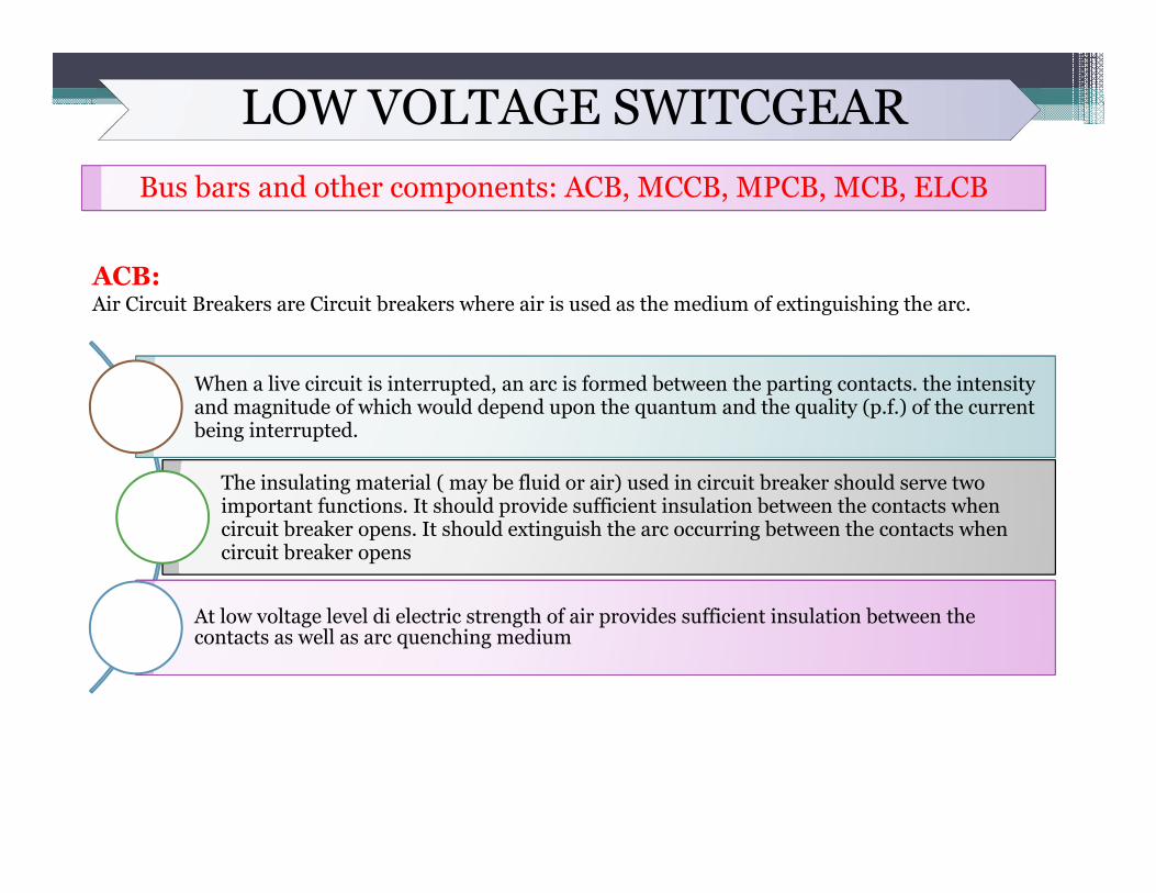
ACB:Air Circuit Breakers are Circuit breakers where air is used as the medium of extinguishing the arc.
When a live circuit is interrupted, an arc is formed between the parting contacts. the intensity and magnitude of which would depend upon the quantum and the quality (p.f.) of the current being interrupted.
The insulating material ( may be fluid or air) used in circuit breaker should serve two important functions. It should provide sufficient insulation between the contacts when circuit breaker opens. It should extinguish the arc occurring between the contacts when circuit breaker opens
At low voltage level di electric strength of air provides sufficient insulation between the contacts as well as arc quenching medium
LOW VOLTAGE SWITCGEARBus bars and other components: ACB, MCCB, MPCB, MCB, ELCB
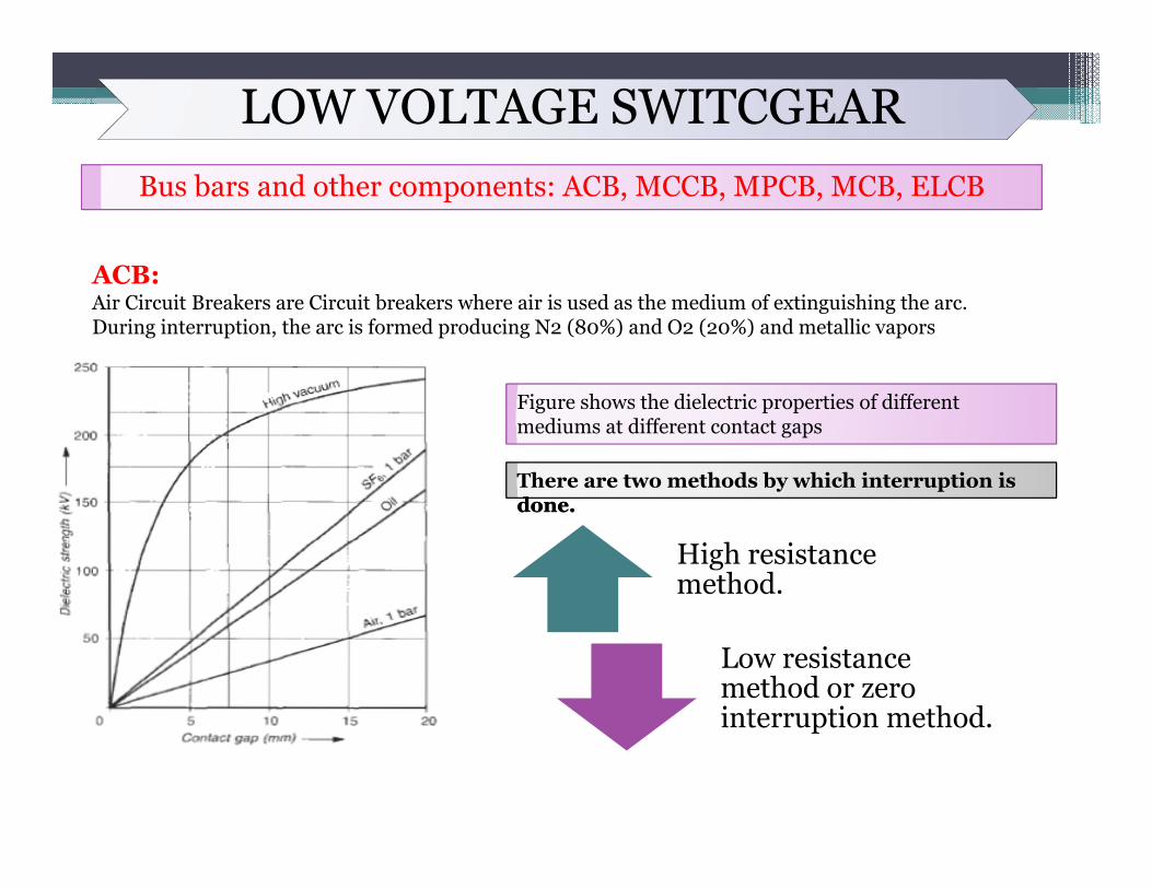
ACB:Air Circuit Breakers are Circuit breakers where air is used as the medium of extinguishing the arc.During interruption, the arc is formed producing N2 (80%) and O2 (20%) and metallic vapors
Figure shows the dielectric properties of different mediums at different contact gaps
done. There are two methods by which interruption is done.
High resistance method.
Low resistance method or zero interruption method.
LOW VOLTAGE SWITCGEARBus bars and other components: ACB, MCCB, MPCB, MCB, ELCB
ACB:
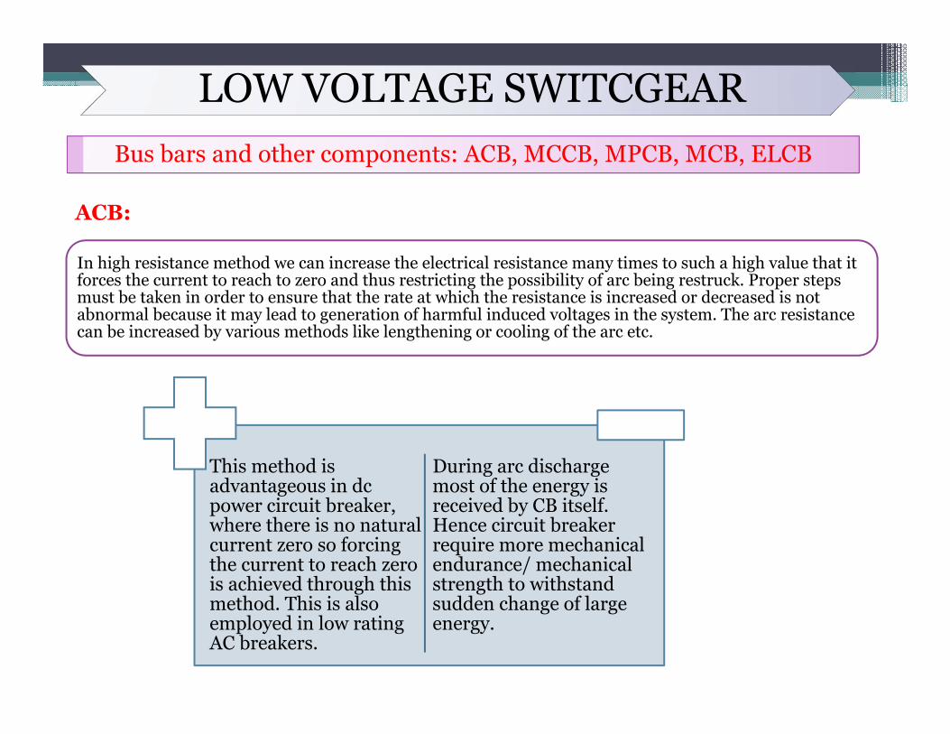
In high resistance method we can increase the electrical resistance many times to such a high value that it forces the current to reach to zero and thus restricting the possibility of arc being restruck. Proper steps must be taken in order to ensure that the rate at which the resistance is increased or decreased is not abnormal because it may lead to generation of harmful induced voltages in the system. The arc resistance can be increased by various methods like lengthening or cooling of the arc etc.
This method is advantageous in dc power circuit breaker, where there is no natural current zero so forcing the current to reach zero is achieved through this method. This is also employed in low rating AC breakers.
During arc discharge most of the energy is received by CB itself. Hence circuit breaker require more mechanical endurance/ mechanical strength to withstand sudden change of large energy.
LOW VOLTAGE SWITCGEARBus bars and other components: ACB, MCCB, MPCB, MCB, ELCB
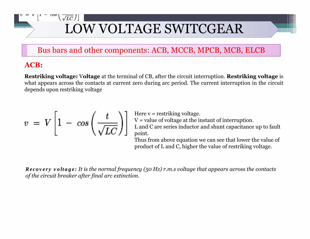
ACB:Restriking voltage: Voltage at the terminal of CB, after the circuit interruption. Restriking voltage iswhat appears across the contacts at current zero during arc period. The current interruption in the circuitdepends upon restriking voltage
Here v = restriking voltage.V = value of voltage at the instant of interruption.L and C are series inductor and shunt capacitance up to fault point.Thus from above equation we can see that lower the value of product of L and C, higher the value of restriking voltage.
Recovery voltage: It is the normal frequency (50 Hz) r.m.s voltage that appears across the contacts of the circuit breaker after final arc extinction.
LOW VOLTAGE SWITCGEARBus bars and other components: ACB, MCCB, MPCB, MCB, ELCB
ACB:
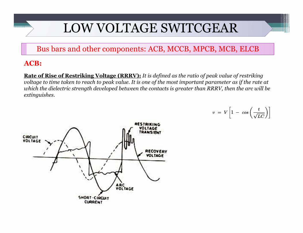
Rate of Rise of Restriking Voltage (RRRV): It is defined as the ratio of peak value of restriking voltage to time taken to reach to peak value. It is one of the most important parameter as if the rate at which the dielectric strength developed between the contacts is greater than RRRV, then the arc will be extinguishes.
LOW VOLTAGE SWITCGEARBus bars and other components: ACB, MCCB, MPCB, MCB, ELCB
ACB:
Low resistance method is applicable only for ac circuit and it is possible there because of presence of natural zero of current. The arc gets extinguished at the natural zero of the ac wave and is prevented from restricting again by rapid building of dielectric strength of the contact space.
There are two theories which explains the phenomenon of arc extinction:
Energy Balance Theory: When the contact of circuit breaker are about to open, hence generated heat would be zero and when the contacts are fully open there is no production of heat. So maximum generated heat is lying between these two cases, this theory is based on the fact that the rate of generation of heat between the contacts of circuit breaker is lower than the rate at which heat between the contact is dissipated. Thus if it is possible to remove the generated heat at a high rate than the generation, than arc can be extinguished.
Voltage Race Theory : The arc is due to the ionization of the gap between the contact of the circuit breaker. As the contact separates the resistance starts increasing. If we remove ions at the initial stage either by recombining them into neutral molecules or inserting insulation at a rate faster than the rate of ionization, the arc can be interrupted.
LOW VOLTAGE SWITCGEARBus bars and other components: ACB, MCCB, MPCB, MCB, ELCB
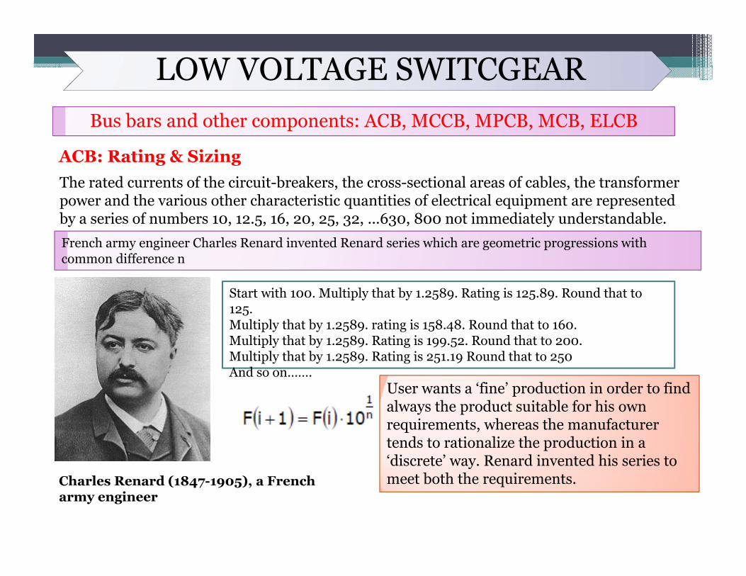
ACB: Rating & SizingThe rated currents of the circuit-breakers, the cross-sectional areas of cables, the transformer power and the various other characteristic quantities of electrical equipment are represented by a series of numbers 10, 12.5, 16, 20, 25, 32, ...630, 800 not immediately understandable.
Charles Renard (1847-1905), a French army engineer
French army engineer Charles Renard invented Renard series which are geometric progressions with common difference n
Start with 100. Multiply that by 1.2589. Rating is 125.89. Round that to 125. Multiply that by 1.2589. rating is 158.48. Round that to 160. Multiply that by 1.2589. Rating is 199.52. Round that to 200. Multiply that by 1.2589. Rating is 251.19 Round that to 250And so on…….
User wants a ‘fine’ production in order to find always the product suitable for his own requirements, whereas the manufacturer tends to rationalize the production in a ‘discrete’ way. Renard invented his series tomeet both the requirements.
LOW VOLTAGE SWITCGEARBus bars and other components: ACB, MCCB, MPCB, MCB, ELCB
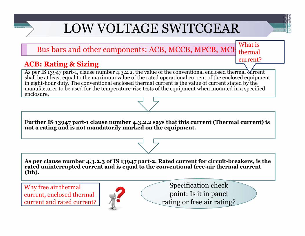
ACB: Rating & Sizing
As per clause number 4.3.2.3 of IS 13947 part-2, Rated current for circuit-breakers, is the rated uninterrupted current and is equal to the conventional free-air thermal current (Ith).
Further IS 13947 part-1 clause number 4.3.2.2 says that this current (Thermal current) is not a rating and is not mandatorily marked on the equipment.
As per IS 13947 part-1, clause number 4.3.2.2, the value of the conventional enclosed thermal current shall be at least equal to the maximum value of the rated operational current of the enclosed equipment in eight-hour duty. The conventional enclosed thermal current is the value of current stated by the manufacturer to be used for the temperature-rise tests of the equipment when mounted in a specified enclosure.
What is thermal current?
Why free air thermal current, enclosed thermal current and rated current? rating or free air rating?
Specification check point: Is it in panel
rating or free air rating?
LOW VOLTAGE SWITCGEARBus bars and other components: ACB, MCCB, MPCB, MCB, ELCB
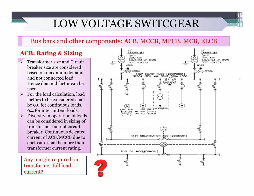
ACB: Rating & Sizing Transformer size and Circuit
breaker size are considered based on maximum demand and not connected load. Hence demand factor can be used.
For the load calculation, load factors to be considered shall be 0.9 for continuous loads, 0.4 for intermittent loads.
Diversity in operation of loads can be considered in sizing of transformer but not circuit breaker. Continuous de-rated current of ACB/MCCB due to enclosure shall be more than transformer current rating.
Any margin required on transformer full load current?
LOW VOLTAGE SWITCGEARBus bars and other components: ACB, MCCB, MPCB, MCB, ELCB
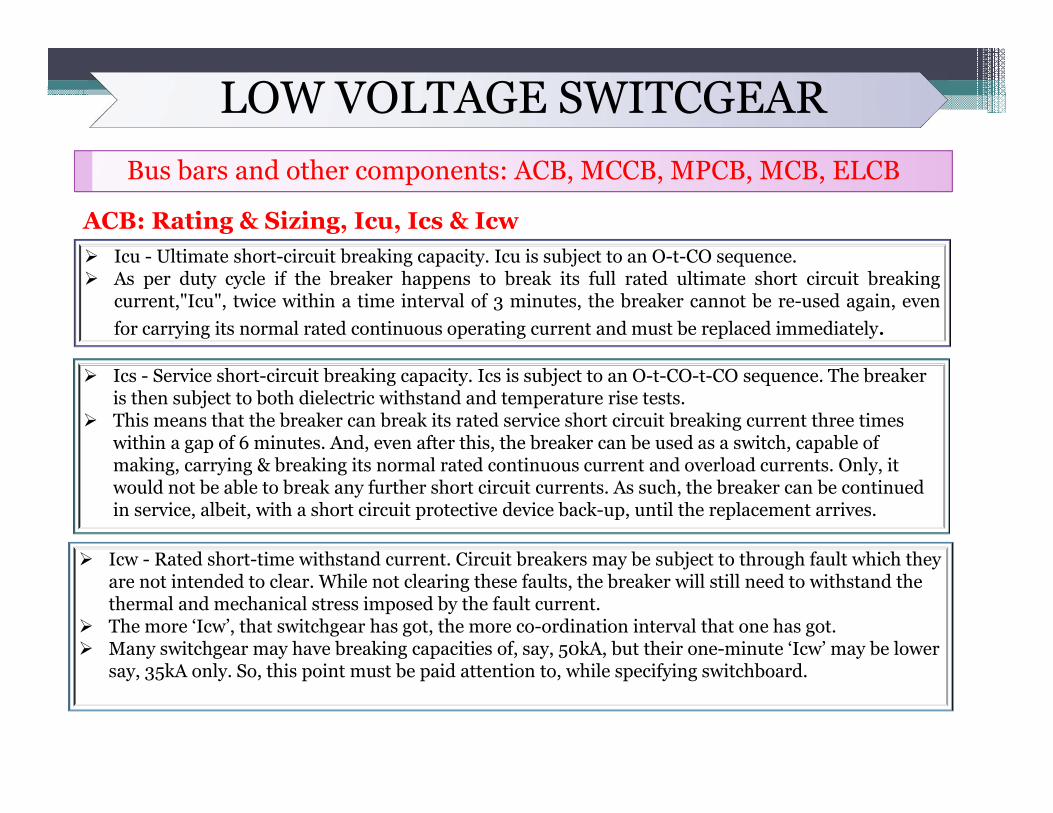
ACB: Rating & Sizing, Icu, Ics & Icw Icu - Ultimate short-circuit breaking capacity. Icu is subject to an O-t-CO sequence. As per duty cycle if the breaker happens to break its full rated ultimate short circuit breaking
current,"Icu", twice within a time interval of 3 minutes, the breaker cannot be re-used again, evenfor carrying its normal rated continuous operating current and must be replaced immediately.
Ics - Service short-circuit breaking capacity. Ics is subject to an O-t-CO-t-CO sequence. The breaker is then subject to both dielectric withstand and temperature rise tests.
This means that the breaker can break its rated service short circuit breaking current three times within a gap of 6 minutes. And, even after this, the breaker can be used as a switch, capable of making, carrying & breaking its normal rated continuous current and overload currents. Only, it would not be able to break any further short circuit currents. As such, the breaker can be continued in service, albeit, with a short circuit protective device back-up, until the replacement arrives.
Icw - Rated short-time withstand current. Circuit breakers may be subject to through fault which they are not intended to clear. While not clearing these faults, the breaker will still need to withstand the thermal and mechanical stress imposed by the fault current.
The more ‘Icw’, that switchgear has got, the more co-ordination interval that one has got. Many switchgear may have breaking capacities of, say, 50kA, but their one-minute ‘Icw’ may be lower
say, 35kA only. So, this point must be paid attention to, while specifying switchboard.
LOW VOLTAGE SWITCGEARBus bars and other components: ACB, MCCB, MPCB, MCB, ELCB
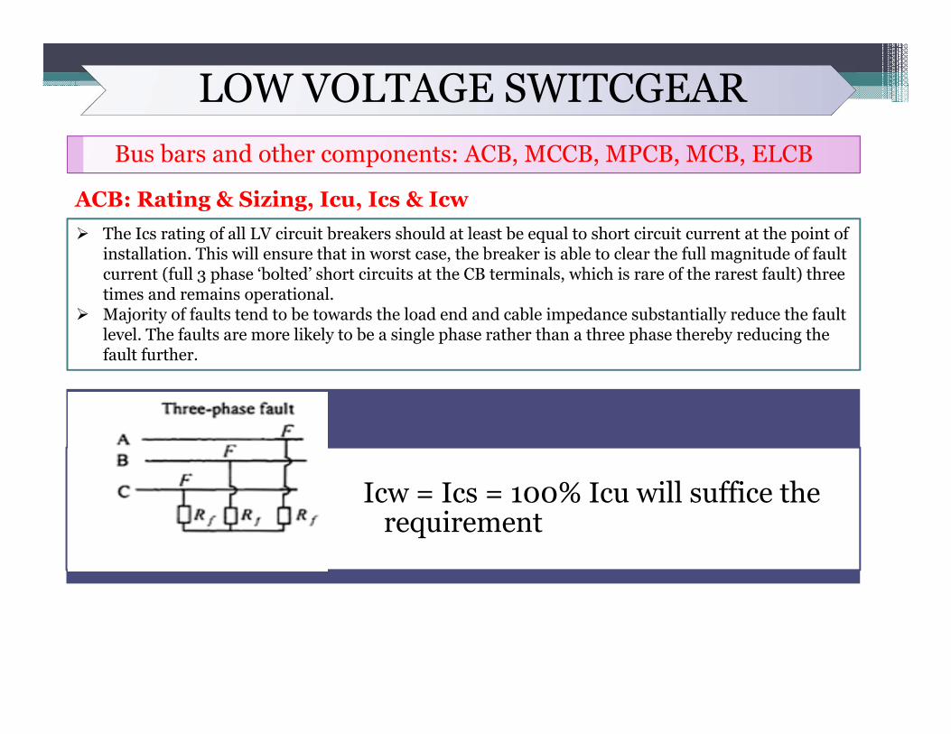
ACB: Rating & Sizing, Icu, Ics & Icw The Ics rating of all LV circuit breakers should at least be equal to short circuit current at the point of
installation. This will ensure that in worst case, the breaker is able to clear the full magnitude of fault current (full 3 phase ‘bolted’ short circuits at the CB terminals, which is rare of the rarest fault) three times and remains operational.
Majority of faults tend to be towards the load end and cable impedance substantially reduce the fault level. The faults are more likely to be a single phase rather than a three phase thereby reducing the fault further.
Icw = Ics = 100% Icu will suffice the requirement
LOW VOLTAGE SWITCGEARBus bars and other components: ACB, MCCB, MPCB, MCB, ELCB
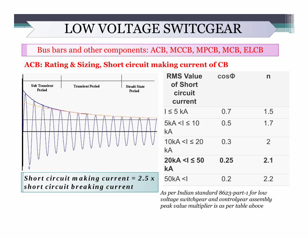
ACB: Rating & Sizing, Short circuit making current of CB
Short circuit making current = 2.5 x short circuit breaking current
RMS Value of Short circuit current
cosΦ n
I ≤ 5 kA 0.7 1.55kA <I ≤ 10 kA
0.5 1.7
10kA <I ≤ 20 kA
0.3 2
20kA <I ≤ 50 kA
0.25 2.1
50kA <I 0.2 2.2
As per Indian standard 8623-part-1 for low voltage switchgear and controlgear assembly peak value multiplier is as per table above
LOW VOLTAGE SWITCGEARBus bars and other components: ACB, MCCB, MPCB, MCB, ELCB
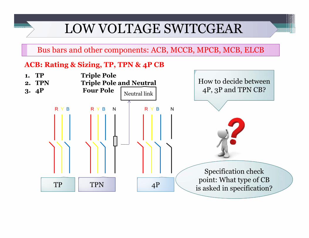
ACB: Rating & Sizing, TP, TPN & 4P CB1. TP Triple Pole2. TPN Triple Pole and Neutral3. 4P Four Pole
R Y B NR Y B R Y B N
TP TPN 4P
How to decide between 4P, 3P and TPN CB?
Specification check point: What type of CB
is asked in specification?
Neutral link
LOW VOLTAGE SWITCGEARBus bars and other components: ACB, MCCB, MPCB, MCB, ELCB
ACB: Rating & Sizing, TP, TPN & 4P CBWhere to use 4 Pole CB instead of TPN CBIn case of parallel operation of DG (For DG and mains or two DG: IS 3043 clause number 23.2.2)In case of multiple incomer to a switchboard:
DG and transformer Two transformer
If one DG is failed and other DG sets are in running condition to feed the loads, and there is some unbalance in loads then depending on degree of unbalance, there will be flow of current through neutral. During this time, if any technician is attending on failed DG incomer and if he touches the neutral conductors (which is earthed) he will get electric shock depending on the potential rise in common neutral due to flow of current through neutral conductor. This problem will also be there if there is standby DG with transformer and their location is different. Three pole breaker with direct neutral earthed at their respective end will cause hazard during maintenance being done at any one of them with other in running condition.
LOW VOLTAGE SWITCGEARBus bars and other components: ACB, MCCB, MPCB, MCB, ELCB
ACB: Rating & Sizing, TP, TPN & 4P CBWhere to use 4 Pole CB instead of TPN CB
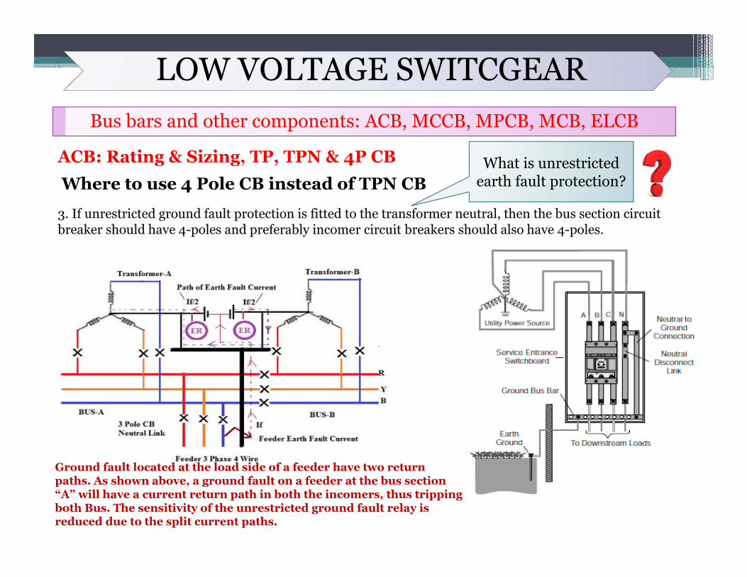
3. If unrestricted ground fault protection is fitted to the transformer neutral, then the bus section circuit breaker should have 4-poles and preferably incomer circuit breakers should also have 4-poles.
What is unrestricted earth fault protection?
Ground fault located at the load side of a feeder have two return paths. As shown above, a ground fault on a feeder at the bus section “A” will have a current return path in both the incomers, thus tripping both Bus. The sensitivity of the unrestricted ground fault relay is reduced due to the split current paths.
LOW VOLTAGE SWITCGEARBus bars and other components: ACB, MCCB, MPCB, MCB, ELCB
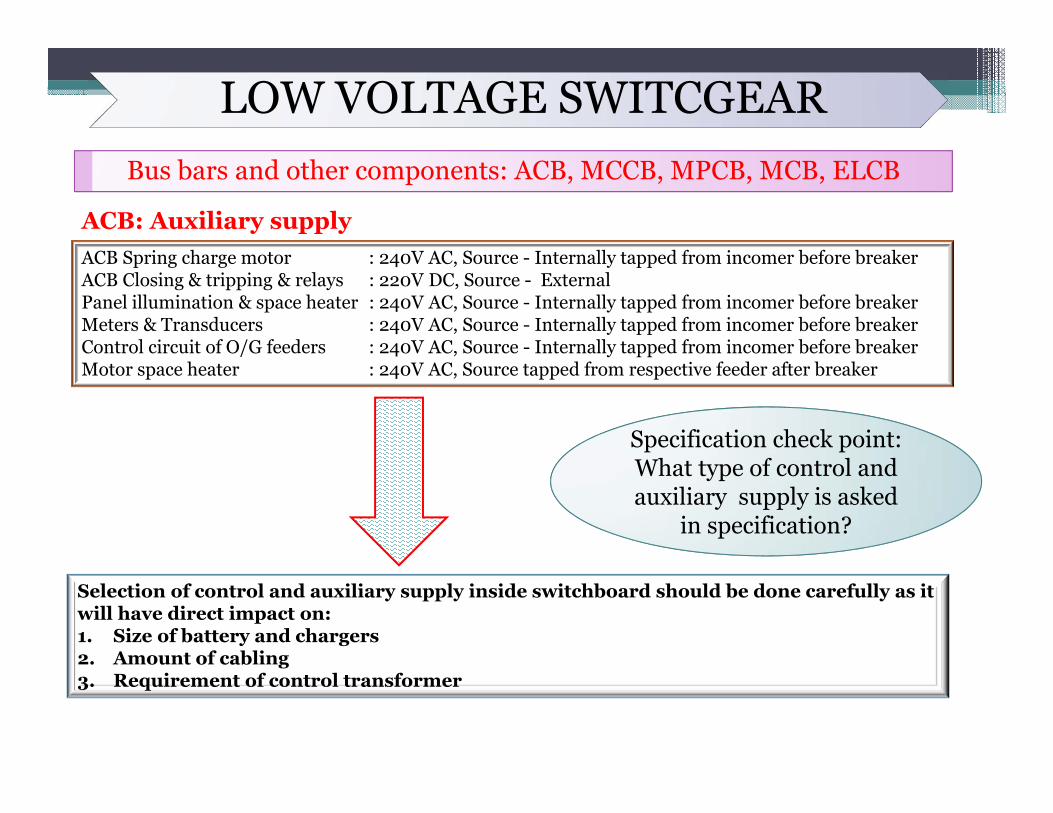
ACB: Auxiliary supplyACB Spring charge motor : 240V AC, Source - Internally tapped from incomer before breakerACB Closing & tripping & relays : 220V DC, Source - ExternalPanel illumination & space heater : 240V AC, Source - Internally tapped from incomer before breakerMeters & Transducers : 240V AC, Source - Internally tapped from incomer before breakerControl circuit of O/G feeders : 240V AC, Source - Internally tapped from incomer before breakerMotor space heater : 240V AC, Source tapped from respective feeder after breaker
Specification check point: What type of control and auxiliary supply is asked
in specification?
Selection of control and auxiliary supply inside switchboard should be done carefully as it will have direct impact on:1. Size of battery and chargers2. Amount of cabling3. Requirement of control transformer
LOW VOLTAGE SWITCGEARBus bars and other components: ACB, MCCB, MPCB, MCB, ELCB
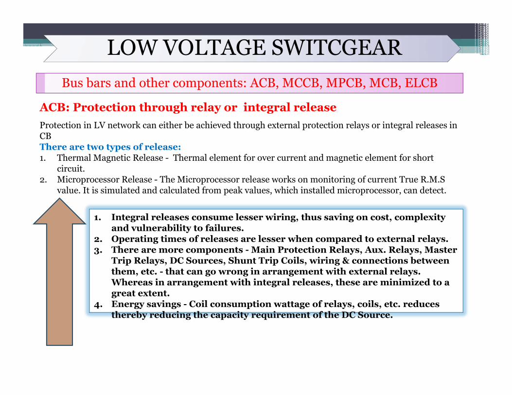
ACB: Protection through relay or integral releaseProtection in LV network can either be achieved through external protection relays or integral releases in CBThere are two types of release:1. Thermal Magnetic Release - Thermal element for over current and magnetic element for short
circuit. 2. Microprocessor Release - The Microprocessor release works on monitoring of current True R.M.S
value. It is simulated and calculated from peak values, which installed microprocessor, can detect.
1. Integral releases consume lesser wiring, thus saving on cost, complexity and vulnerability to failures.
2. Operating times of releases are lesser when compared to external relays.3. There are more components - Main Protection Relays, Aux. Relays, Master
Trip Relays, DC Sources, Shunt Trip Coils, wiring & connections between them, etc. - that can go wrong in arrangement with external relays. Whereas in arrangement with integral releases, these are minimized to a great extent.
4. Energy savings - Coil consumption wattage of relays, coils, etc. reduces thereby reducing the capacity requirement of the DC Source.
LOW VOLTAGE SWITCGEARBus bars and other components: ACB, MCCB, MPCB, MCB, ELCB
MCCB
What is an MCCB?
“A mechanical switching device, capable of making, carrying and breaking currents under normal circuit conditions and also making, carrying for a specified time and breaking currents under specified abnormal circuit condition such as those of short circuits.”
Same definition as given in ACB in slide no-43 than what is the difference?
LOW VOLTAGE SWITCGEARBus bars and other components: ACB, MCCB, MPCB, MCB, ELCB
MCCB
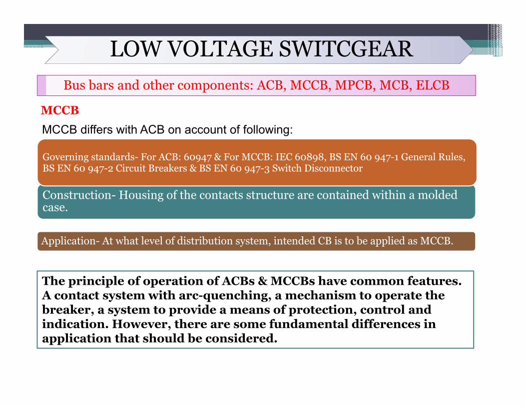
MCCB differs with ACB on account of following:
Construction- Housing of the contacts structure are contained within a molded case.
Application- At what level of distribution system, intended CB is to be applied as MCCB.
Governing standards- For ACB: 60947 & For MCCB: IEC 60898, BS EN 60 947-1 General Rules, BS EN 60 947-2 Circuit Breakers & BS EN 60 947-3 Switch Disconnector
The principle of operation of ACBs & MCCBs have common features.A contact system with arc-quenching, a mechanism to operate the breaker, a system to provide a means of protection, control and indication. However, there are some fundamental differences in application that should be considered.
LOW VOLTAGE SWITCGEARBus bars and other components: ACB, MCCB, MPCB, MCB, ELCB
MCCB
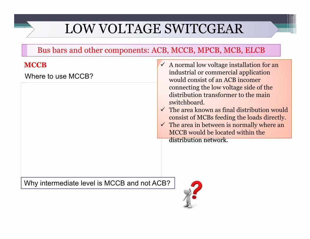
Where to use MCCB?This image cannot currently be displayed.
distribution network.
A normal low voltage installation for an industrial or commercial application would consist of an ACB incomer connecting the low voltage side of the distribution transformer to the main switchboard.
The area known as final distribution would consist of MCBs feeding the loads directly.
The area in between is normally where an MCCB would be located within the distribution network.
Why intermediate level is MCCB and not ACB?
LOW VOLTAGE SWITCGEARBus bars and other components: ACB, MCCB, MPCB, MCB, ELCB
MCCB
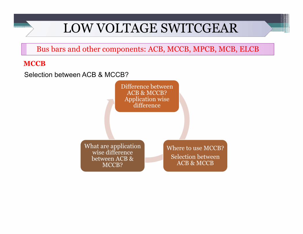
Selection between ACB & MCCB?
Difference between ACB & MCCB?
Application wise difference
Where to use MCCB? Selection between
ACB & MCCB
What are application wise difference between ACB &
MCCB?
LOW VOLTAGE SWITCGEARBus bars and other components: ACB, MCCB, MPCB, MCB, ELCB
MCCB
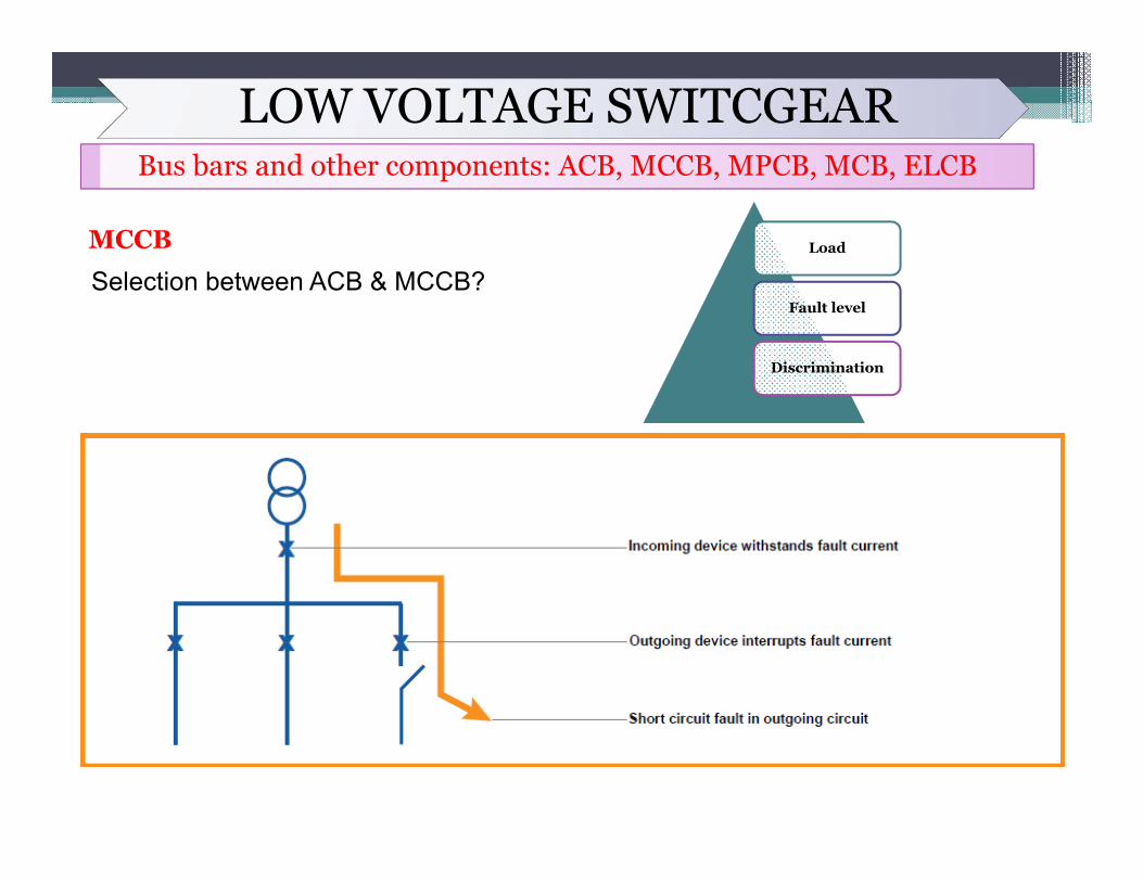
Selection between ACB & MCCB?Load
Fault level
Discrimination
LOW VOLTAGE SWITCGEARBus bars and other components: ACB, MCCB, MPCB, MCB, ELCB
MCCB
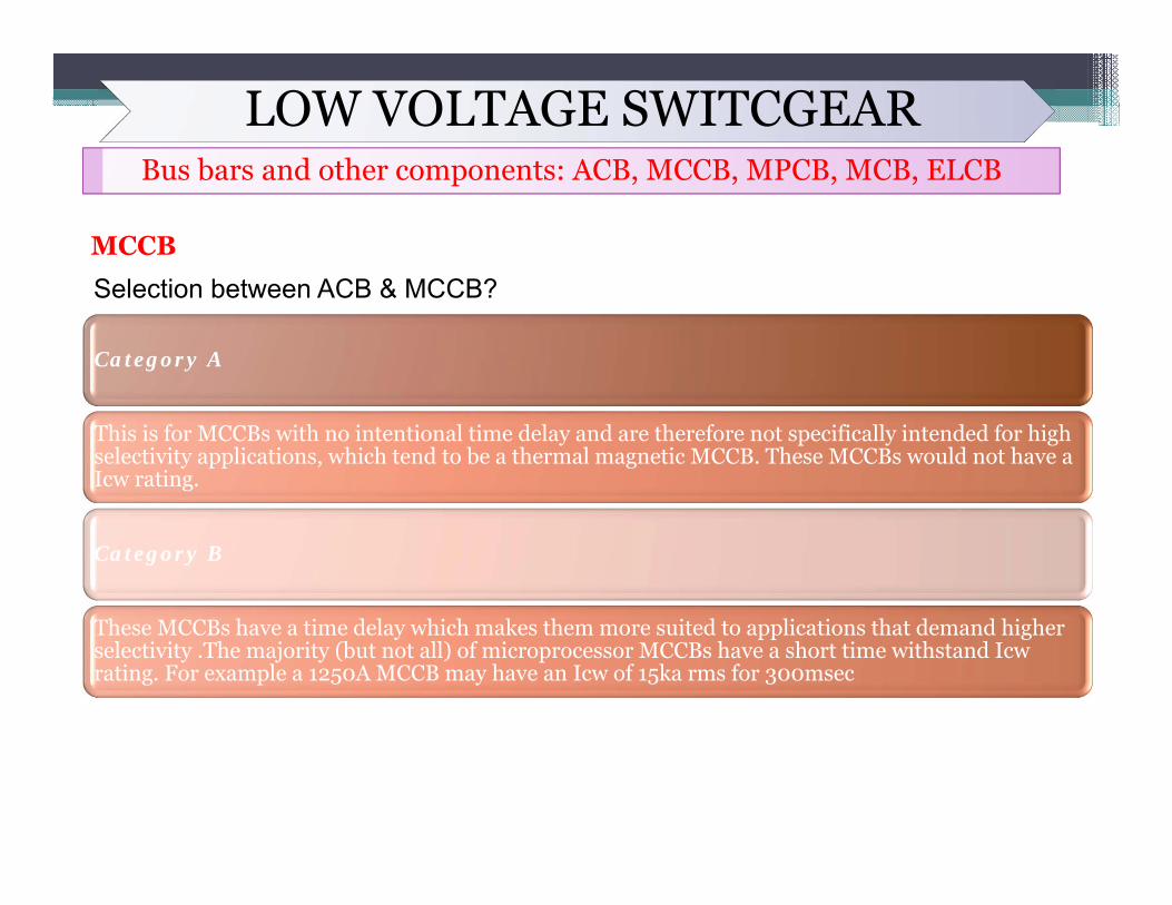
Selection between ACB & MCCB?
Category A
This is for MCCBs with no intentional time delay and are therefore not specifically intended for high selectivity applications, which tend to be a thermal magnetic MCCB. These MCCBs would not have a Icw rating.
Category B
These MCCBs have a time delay which makes them more suited to applications that demand higher selectivity .The majority (but not all) of microprocessor MCCBs have a short time withstand Icwrating. For example a 1250A MCCB may have an Icw of 15ka rms for 300msec
LOW VOLTAGE SWITCGEARBus bars and other components: ACB, MCCB, MPCB, MCB, ELCB
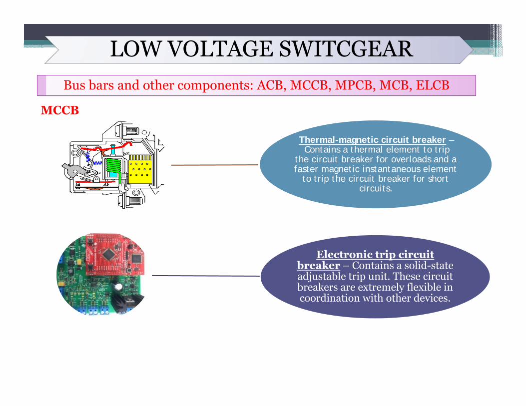
MCCB
Thermal-magnetic circuit breaker –Contains a thermal element to trip
the circuit breaker for overloads and a faster magnetic instantaneous element
to trip the circuit breaker for short circuits.
Electronic trip circuit breaker – Contains a solid-state adjustable trip unit. These circuit breakers are extremely flexible in coordination with other devices.
LOW VOLTAGE SWITCGEARBus bars and other components: ACB, MCCB, MPCB, MCB, ELCB
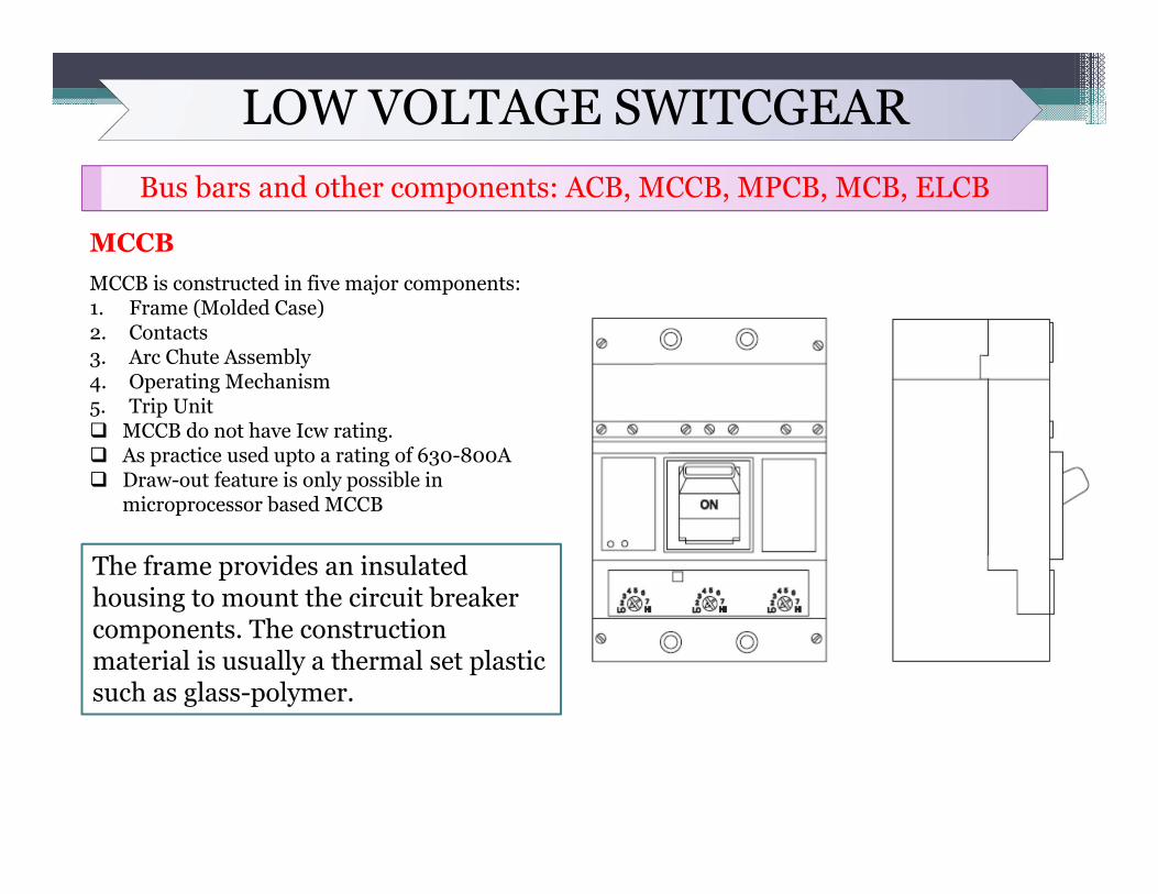
MCCBMCCB is constructed in five major components:1. Frame (Molded Case)2. Contacts3. Arc Chute Assembly4. Operating Mechanism5. Trip Unit MCCB do not have Icw rating. As practice used upto a rating of 630-800A Draw-out feature is only possible in
microprocessor based MCCB
The frame provides an insulated housing to mount the circuit breaker components. The construction material is usually a thermal set plastic such as glass-polymer.
LOW VOLTAGE SWITCGEARBus bars and other components: ACB, MCCB, MPCB, MCB, ELCB
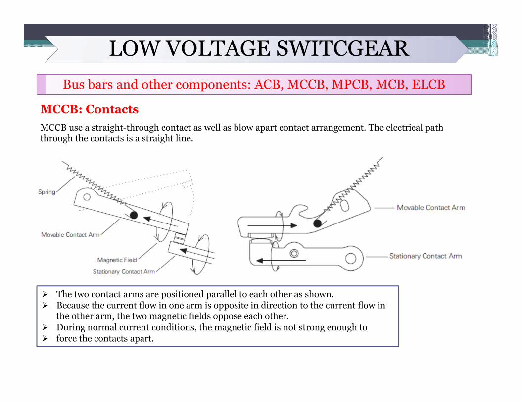
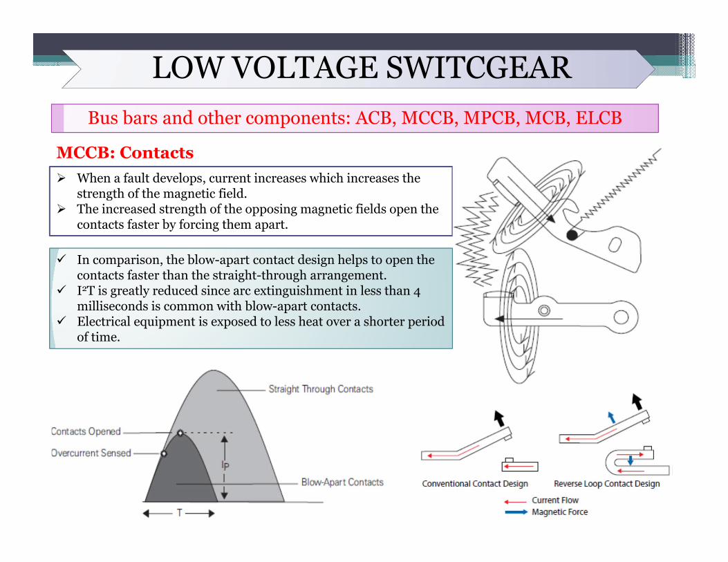
MCCB: ContactsMCCB use a straight-through contact as well as blow apart contact arrangement. The electrical path through the contacts is a straight line.
The two contact arms are positioned parallel to each other as shown. Because the current flow in one arm is opposite in direction to the current flow in
the other arm, the two magnetic fields oppose each other. During normal current conditions, the magnetic field is not strong enough to force the contacts apart.
LOW VOLTAGE SWITCGEARBus bars and other components: ACB, MCCB, MPCB, MCB, ELCB
MCCB: Contacts When a fault develops, current increases which increases the
strength of the magnetic field. The increased strength of the opposing magnetic fields open the
contacts faster by forcing them apart.
In comparison, the blow-apart contact design helps to open the contacts faster than the straight-through arrangement.
I2T is greatly reduced since arc extinguishment in less than 4 milliseconds is common with blow-apart contacts.
Electrical equipment is exposed to less heat over a shorter period of time.
LOW VOLTAGE SWITCGEARBus bars and other components: ACB, MCCB, MPCB, MCB, ELCB
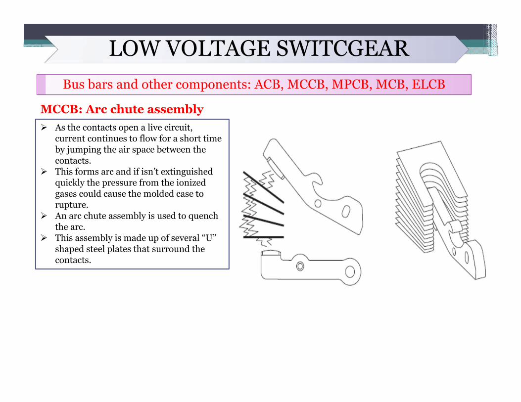
MCCB: Arc chute assembly As the contacts open a live circuit,
current continues to flow for a short time by jumping the air space between the contacts.
This forms arc and if isn’t extinguished quickly the pressure from the ionized gases could cause the molded case to rupture.
An arc chute assembly is used to quench the arc.
This assembly is made up of several “U” shaped steel plates that surround the contacts.
LOW VOLTAGE SWITCGEARBus bars and other components: ACB, MCCB, MPCB, MCB, ELCB
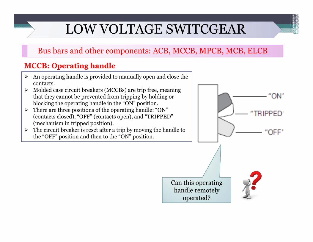
MCCB: Operating handle An operating handle is provided to manually open and close the
contacts. Molded case circuit breakers (MCCBs) are trip free, meaning
that they cannot be prevented from tripping by holding or blocking the operating handle in the “ON” position.
There are three positions of the operating handle: “ON” (contacts closed), “OFF” (contacts open), and “TRIPPED” (mechanism in tripped position).
The circuit breaker is reset after a trip by moving the handle to the “OFF” position and then to the “ON” position.
Can this operating handle remotely
operated?
LOW VOLTAGE SWITCGEARBus bars and other components: ACB, MCCB, MPCB, MCB, ELCB
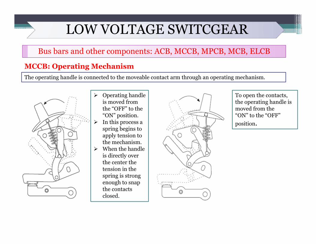
MCCB: Operating MechanismThe operating handle is connected to the moveable contact arm through an operating mechanism.
Operating handle is moved from the “OFF” to the “ON” position.
In this process a spring begins to apply tension to the mechanism.
When the handle is directly over the center the tension in the spring is strong enough to snap the contacts closed.
To open the contacts, the operating handle is moved from the“ON” to the “OFF” position.
LOW VOLTAGE SWITCGEARBus bars and other components: ACB, MCCB, MPCB, MCB, ELCB
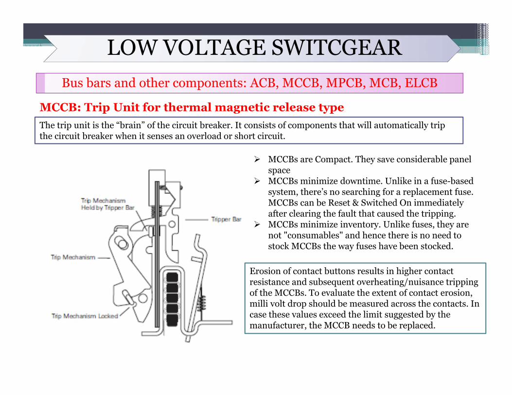
MCCB: Trip Unit for thermal magnetic release typeThe trip unit is the “brain” of the circuit breaker. It consists of components that will automatically trip the circuit breaker when it senses an overload or short circuit.
MCCBs are Compact. They save considerable panel space
MCCBs minimize downtime. Unlike in a fuse-based system, there’s no searching for a replacement fuse. MCCBs can be Reset & Switched On immediately after clearing the fault that caused the tripping.
MCCBs minimize inventory. Unlike fuses, they are not "consumables" and hence there is no need to stock MCCBs the way fuses have been stocked.
Erosion of contact buttons results in higher contact resistance and subsequent overheating/nuisance tripping of the MCCBs. To evaluate the extent of contact erosion, milli volt drop should be measured across the contacts. In case these values exceed the limit suggested by the manufacturer, the MCCB needs to be replaced.
LOW VOLTAGE SWITCGEARBus bars and other components: ACB, MCCB, MPCB, MCB, ELCB
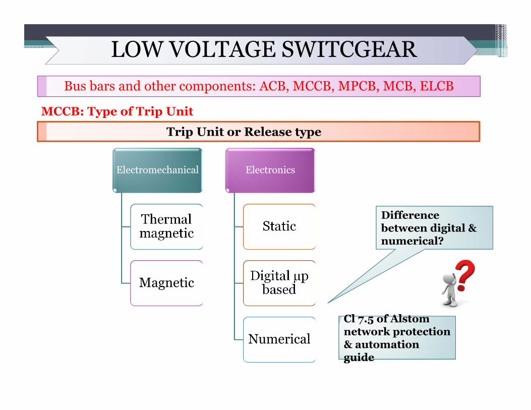
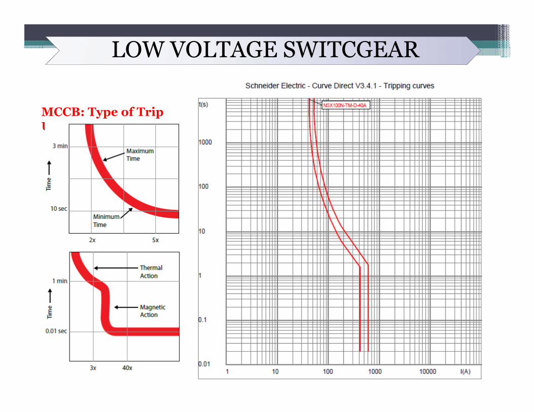
MCCB: Type of Trip Unit
Trip Unit or Release type
Electromechanical
Thermal magnetic
Magnetic
Electronics
Static
Digital µp based
Numerical
Difference between digital & numerical?
Cl f Al t
guide
Cl 7.5 of Alstom network protection & automation guide
LOW VOLTAGE SWITCGEARBus bars and other components: ACB, MCCB, MPCB, MCB, ELCB
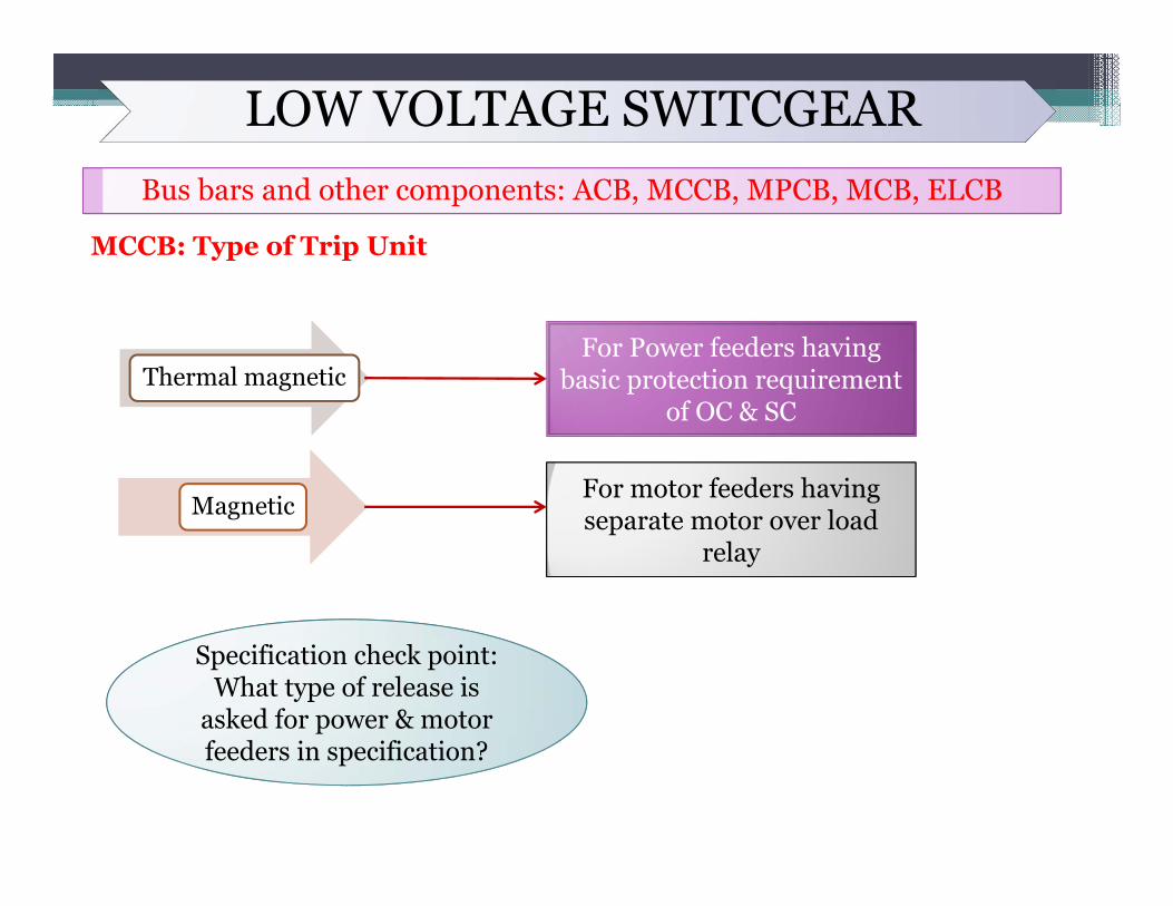
MCCB: Type of Trip Unit
Thermal magneticFor Power feeders having
basic protection requirement of OC & SC
MagneticFor motor feeders having separate motor over load
relay
Specification check point: Specification check point: What type of release is
asked for power & motor feeders in specification?
LOW VOLTAGE SWITCGEARBus bars and other components: ACB, MCCB, MPCB, MCB, ELCB
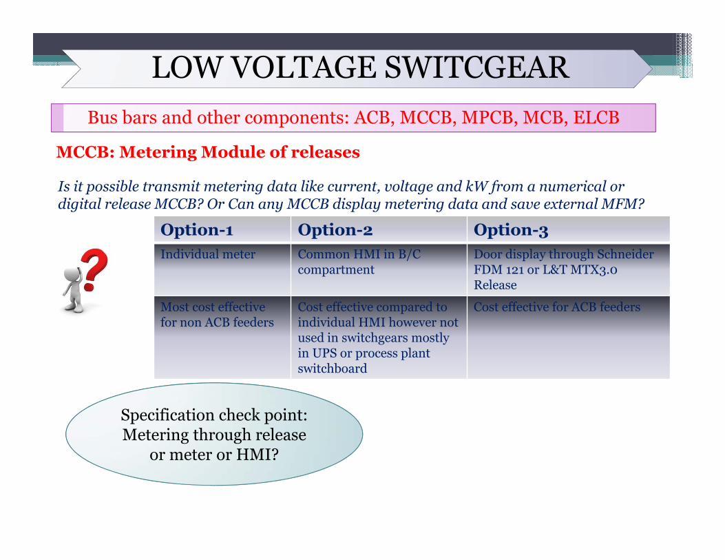
MCCB: Metering Module of releases
Specification check point: Metering through release
or meter or HMI?
Is it possible transmit metering data like current, voltage and kW from a numerical or digital release MCCB? Or Can any MCCB display metering data and save external MFM?
Option-1 Option-2 Option-3Individual meter Common HMI in B/C
compartmentDoor display through Schneider FDM 121 or L&T MTX3.0Release
Most cost effective for non ACB feeders
Cost effective compared to individual HMI however not used in switchgears mostly in UPS or process plant switchboard
Cost effective for ACB feeders
LOW VOLTAGE SWITCGEAR
MCCB: Type of Trip Unit
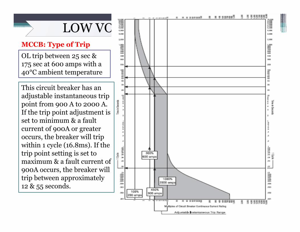
LOW VOLTAGE SWITCGEARMCCB: Type of Trip UnitOL trip between 25 sec & 175 sec at 600 amps with a 40°C ambient temperature
This circuit breaker has anadjustable instantaneous trip point from 900 A to 2000 A.If the trip point adjustment is set to minimum & a fault current of 900A or greater occurs, the breaker will trip within 1 cycle (16.8ms). If the trip point setting is set to maximum & a fault current of 900A occurs, the breaker will trip between approximately 12 & 55 seconds.
LOW VOLTAGE SWITCGEARMCCB: Type of Trip Unit
Frame Size – The term Frame size is applied to a group of circuit breakers of similar configuration. Frame size is expressed in amperes and corresponds to the largest ampere rating available in that group.
Interchangeable Trip - The user does not have access to the trip unit on some Circuit Breakers. This means the trip unit cannot be changed with another. Interchangeable trip is a design feature that is available on some thermal-magnetic and solid state breakers. The advantage of a breaker with an interchangeable trip unit is that the user can change the continuous current rating of the breaker without replacing the breaker. This is done by replacing the trip unit with one of a different rating.
GE Frame Sizes: three basic frame sizes up-to 800A. First frame covers 3.2A to160 A, Second in 200 / 250 / 400A and third in 400 / 630 / 800A.
Specification check point: Specification check point: Interchangeable trip units asked in specification or
not?
LOW VOLTAGE SWITCGEARMCCB
guides\Guides\MCCB Tech details\L&T MCCB_Technical details.xlsxguides\Guides\MCCB Tech details\Schneider MCCB_Technical details.xlsx
Fuse based system:In this system MCB & MCCB is not used at all. Till 630 Ampere fuse is used and above 630 Ampere ACB is used.• In any switchgear with two incomer and buscoupler, If fuse is used than changeover has to be manual,
because with fuse you cannot attain automatic changeover. where as if MCCB is used you can attain automatic changeover.
• Whenever we say fuse it means we are supposed to use SFU or SDF that is switch fuse unit or switch disconnect fuse.
• In case of MCCB you get spare contacts for remote indications and if you use MCCB with shunt trip coil you can even use it for remote tripping and operation with relays. Same is exactly not possible with fuse
• In case of SFU of say 132 Ampere please note that the rating should be indicated as 132/132 or 132/150 ampere where numerator indicates fuse rating and denominator denotes switch rating. Generally switch rating is next higher side to fuse rating but even if it is same no issues, it should be left to vendor as different manufacturer have different standards.
Comparison between Fuse based and fuse less system:Broadly because of following advantages fuse based system is preferred:
• Fuse has high rupturing capacity.• Fuse has shortest operating time.• Because of quick operating time of fuse we do not need to check the SC criteria at all for LT power cables• Thermel magnetic MCCB is to be used below 160 Ampere which has operational history of nuisance
tripping.• Only disadvantage of fuse is that once blown it has to be replaced so spare should be available.

LOW VOLTAGE SWITCGEARBus bars and other components: ACB, MCCB, MPCB, MCB, ELCB
MCBConstruction wise MCB is similar to MCCB with exception that it is available in lower kA rating hence it is of small frame size and hence the name miniature circuit breaker As practice used up-to a rating of 125A Motorized operation not possible because of small size hence not
available with shunt trip coils for remote operation Available with auxiliary contacts
Tripping class
Application
B Fast Acting. Instantaneous trip responseof 3 - 5X rated current (In). Used for sensitive equipment and purely resistive loads.
C Normal acting. Instantaneous trip response of 5 - 10x rated current (In). Used for control circuits and mixed loads
D Slow Acting. Instantaneous trip response of 10 - 20x rated current (In). Used for motor, transformer and solenoid applications.
LOW VOLTAGE SWITCGEARBus bars and other components: ACB, MCCB, MPCB, MCB, ELCB
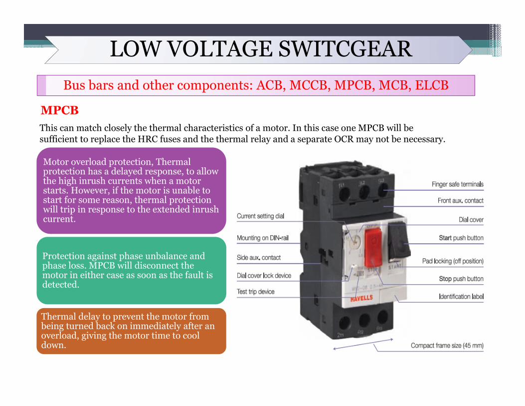
MPCBThis can match closely the thermal characteristics of a motor. In this case one MPCB will besufficient to replace the HRC fuses and the thermal relay and a separate OCR may not be necessary.
Motor overload protection, Thermal protection has a delayed response, to allow the high inrush currents when a motor starts. However, if the motor is unable to start for some reason, thermal protection will trip in response to the extended inrush current.
Protection against phase unbalance and phase loss. MPCB will disconnect the motor in either case as soon as the fault is detected.
Thermal delay to prevent the motor from being turned back on immediately after an overload, giving the motor time to cool down.
LOW VOLTAGE SWITCGEARBus bars and other components: ACB, MCCB, MPCB, MCB, ELCB
ELCB
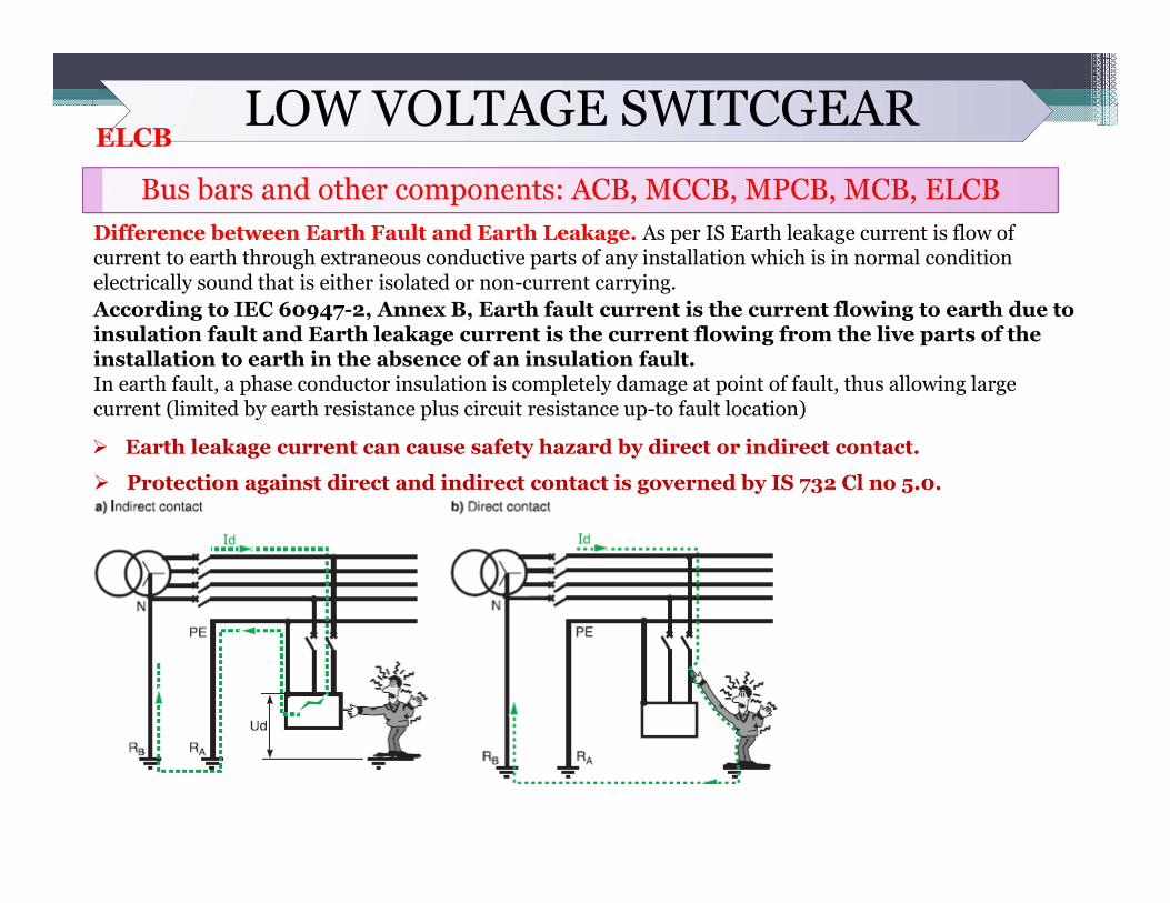
Difference between Earth Fault and Earth Leakage. As per IS Earth leakage current is flow of current to earth through extraneous conductive parts of any installation which is in normal condition electrically sound that is either isolated or non-current carrying.According to IEC 60947-2, Annex B, Earth fault current is the current flowing to earth due to insulation fault and Earth leakage current is the current flowing from the live parts of the installation to earth in the absence of an insulation fault. In earth fault, a phase conductor insulation is completely damage at point of fault, thus allowing large current (limited by earth resistance plus circuit resistance up-to fault location)
Earth leakage current can cause safety hazard by direct or indirect contact.
Protection against direct and indirect contact is governed by IS 732 Cl no 5.0.
LOW VOLTAGE SWITCGEARBus bars and other components: ACB, MCCB, MPCB, MCB, ELCB
ELCB
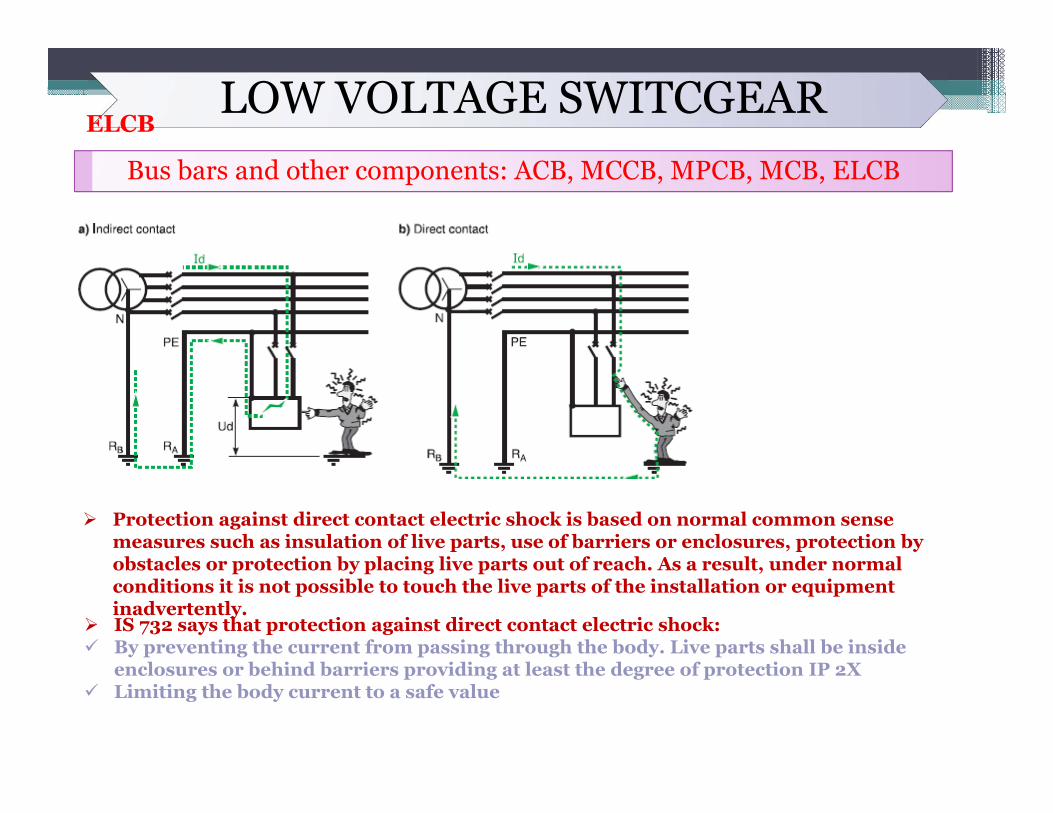
Protection against direct contact electric shock is based on normal common sense measures such as insulation of live parts, use of barriers or enclosures, protection by obstacles or protection by placing live parts out of reach. As a result, under normal conditions it is not possible to touch the live parts of the installation or equipment inadvertently.
IS 732 says that protection against direct contact electric shock: By preventing the current from passing through the body. Live parts shall be inside
enclosures or behind barriers providing at least the degree of protection IP 2X Limiting the body current to a safe value
LOW VOLTAGE SWITCGEARBus bars and other components: ACB, MCCB, MPCB, MCB, ELCB
ELCB
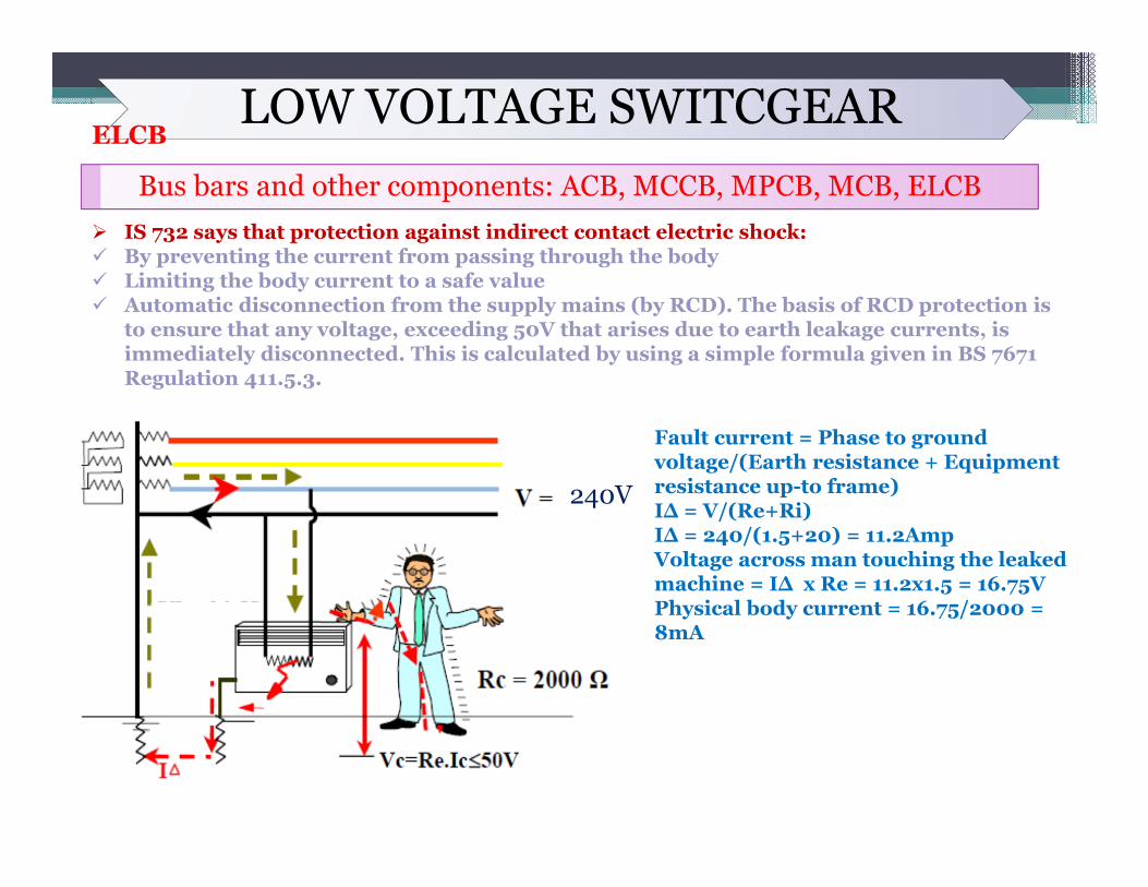
Fault current = Phase to ground voltage/(Earth resistance + Equipment resistance up-to frame)I∆ = V/(Re+Ri)I∆ = 240/(1.5+20) = 11.2AmpVoltage across man touching the leaked machine = I∆ x Re = 11.2x1.5 = 16.75VPhysical body current = 16.75/2000 = 8mA
240V
IS 732 says that protection against indirect contact electric shock: By preventing the current from passing through the body Limiting the body current to a safe value Automatic disconnection from the supply mains (by RCD). The basis of RCD protection is
to ensure that any voltage, exceeding 50V that arises due to earth leakage currents, is immediately disconnected. This is calculated by using a simple formula given in BS 7671 Regulation 411.5.3.
LOW VOLTAGE SWITCGEARBus bars and other components: ACB, MCCB, MPCB, MCB, ELCB
ELCB
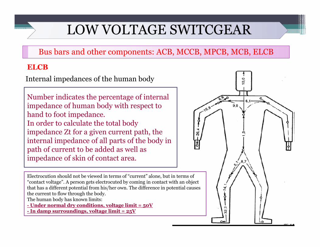
Internal impedances of the human body
Number indicates the percentage of internal impedance of human body with respect to hand to foot impedance.In order to calculate the total body impedance Zt for a given current path, the internal impedance of all parts of the body in path of current to be added as well as impedance of skin of contact area.
Electrocution should not be viewed in terms of “current” alone, but in terms of “contact voltage”. A person gets electrocuted by coming in contact with an object that has a different potential from his/her own. The difference in potential causes the current to flow through the body.The human body has known limits:- Under normal dry conditions, voltage limit = 50V- In damp surroundings, voltage limit = 25V
LOW VOLTAGE SWITCGEARBus bars and other components: ACB, MCCB, MPCB, MCB, ELCB
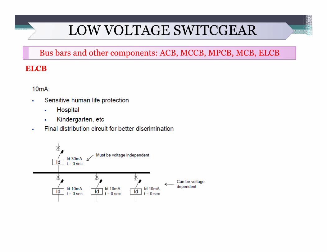
ELCB
LOW VOLTAGE SWITCGEARBus bars and other components: ACB, MCCB, MPCB, MCB, ELCB
ELCB
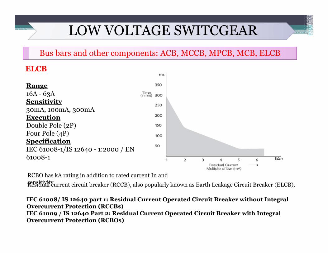
Range16A - 63ASensitivity30mA, 100mA, 300mAExecutionDouble Pole (2P)Four Pole (4P)SpecificationIEC 61008-1/IS 12640 - 1:2000 / EN 61008-1
Residual current circuit breaker (RCCB), also popularly known as Earth Leakage Circuit Breaker (ELCB).
IEC 61008/ IS 12640 part 1: Residual Current Operated Circuit Breaker without Integral Overcurrent Protection (RCCBs)IEC 61009 / IS 12640 Part 2: Residual Current Operated Circuit Breaker with Integral Overcurrent Protection (RCBOs)
RCBO has kA rating in addition to rated current In and sensitivity
LOW VOLTAGE SWITCGEARBus bars and other components: ACB, MCCB, MPCB, MCB, ELCB
ELCBRCDs may be distinguished by their technology, as follows. Voltage Independent RCDs. These RCDs rely on the energy of the residual current to activate the RCD. These devices are sometimes referred to as Electromechanical RCDs, and are voltage-independent in operation.Voltage Dependent RCDs. These RCDs use the mains supply voltage to power an electronic circuit and the tripping mechanism to activate the RCD. These devices are sometimes referred to as Electronic RCDs and are voltage-dependent in operation.
LOW VOLTAGE SWITCGEARBus bars and other components: ACB, MCCB, MPCB, MCB, ELCB
ELCB
LOW VOLTAGE SWITCGEARBus bars and other components: ACB, MCCB, MPCB, MCB, ELCB
ELCB
LOW VOLTAGE SWITCGEARBus bars and other components: ACB, MCCB, MPCB, MCB, ELCB
ELCB
LOW VOLTAGE SWITCGEARBus bars and other components: ACB, MCCB, MPCB, MCB, ELCB
ELCB
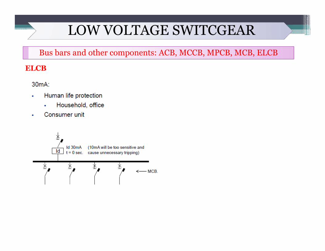
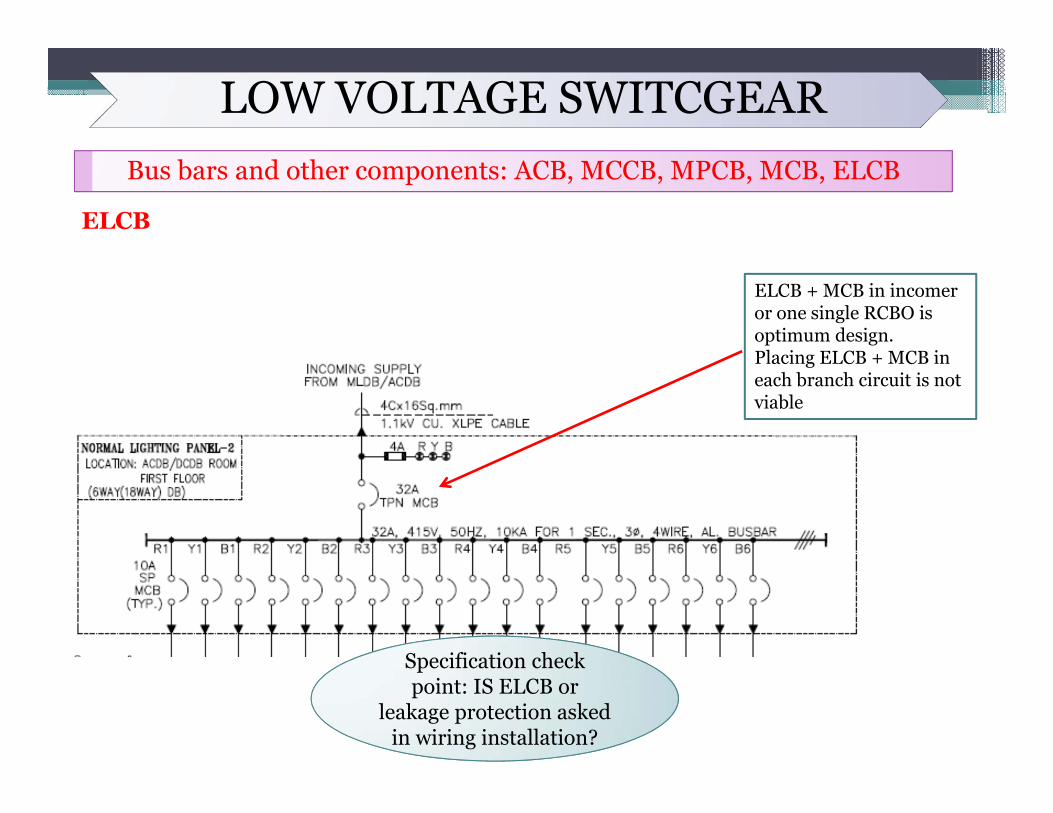
ELCB + MCB in incomer or one single RCBO is optimum design. Placing ELCB + MCB in each branch circuit is not viable
Specification check point: IS ELCB or
leakage protection asked in wiring installation?
LOW VOLTAGE SWITCGEARWiring Schemes & type of feeders
Different terminology in schemes
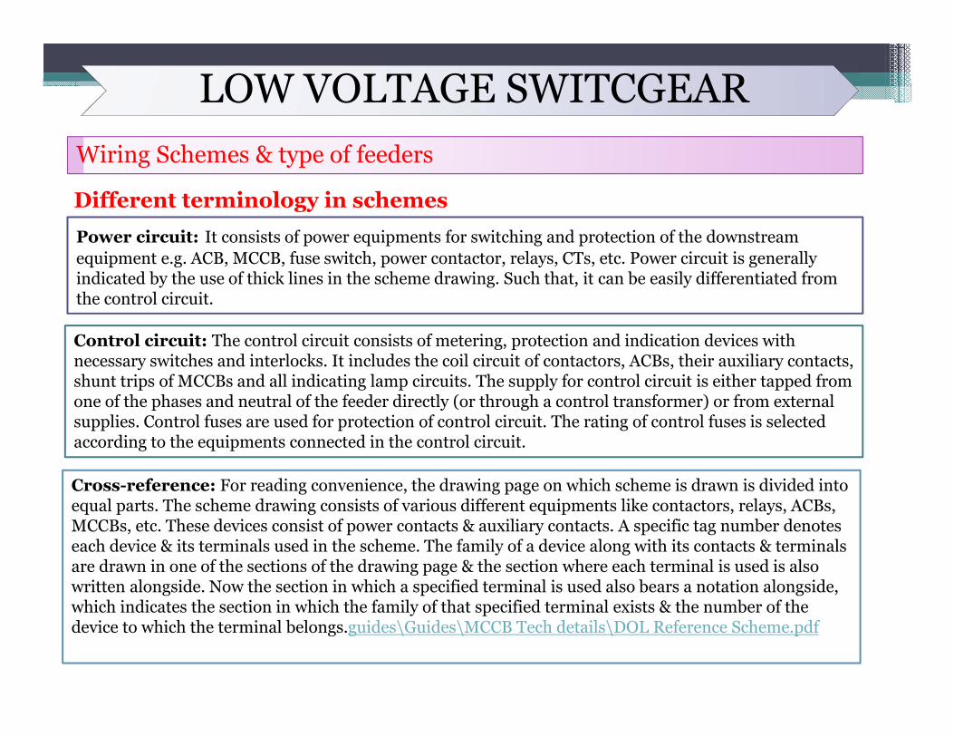
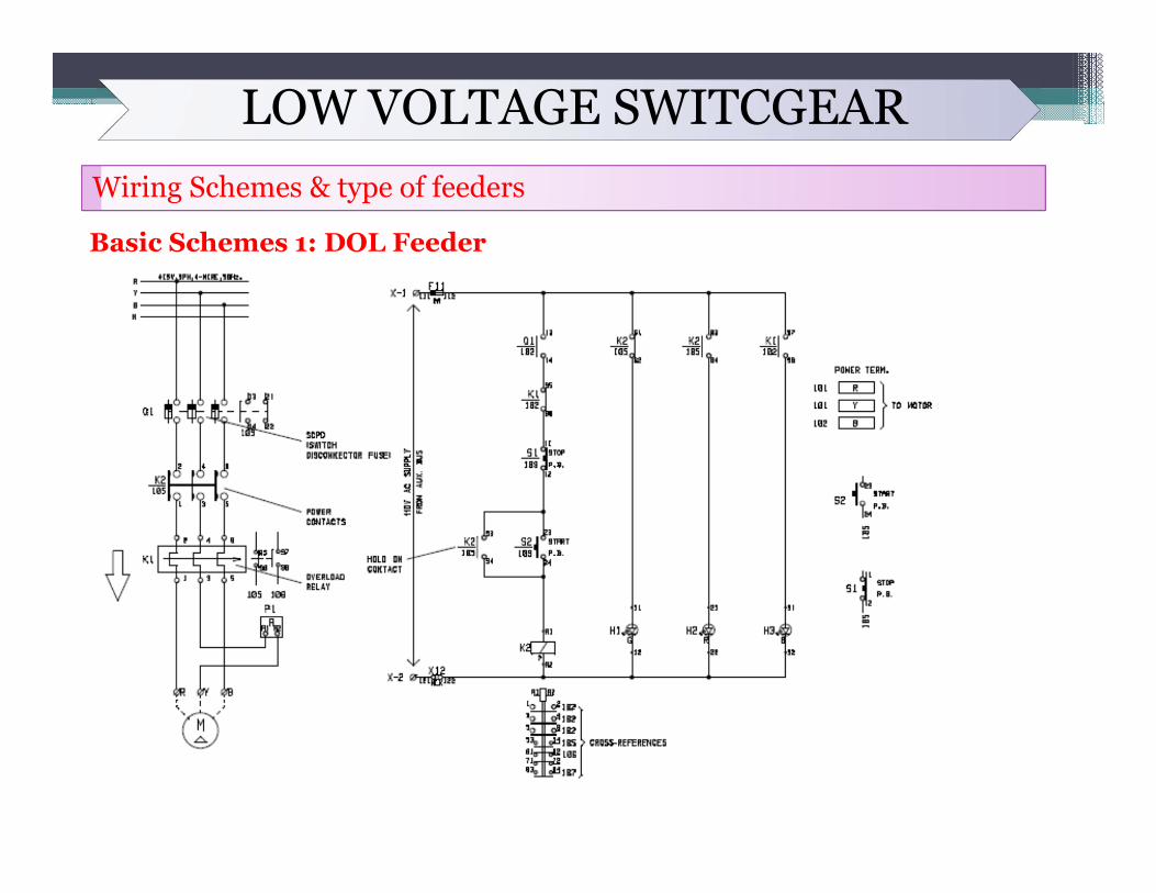
Power circuit: It consists of power equipments for switching and protection of the downstream equipment e.g. ACB, MCCB, fuse switch, power contactor, relays, CTs, etc. Power circuit is generally indicated by the use of thick lines in the scheme drawing. Such that, it can be easily differentiated from the control circuit.
Control circuit: The control circuit consists of metering, protection and indication devices with necessary switches and interlocks. It includes the coil circuit of contactors, ACBs, their auxiliary contacts, shunt trips of MCCBs and all indicating lamp circuits. The supply for control circuit is either tapped from one of the phases and neutral of the feeder directly (or through a control transformer) or from external supplies. Control fuses are used for protection of control circuit. The rating of control fuses is selectedaccording to the equipments connected in the control circuit.
Cross-reference: For reading convenience, the drawing page on which scheme is drawn is divided into equal parts. The scheme drawing consists of various different equipments like contactors, relays, ACBs, MCCBs, etc. These devices consist of power contacts & auxiliary contacts. A specific tag number denotes each device & its terminals used in the scheme. The family of a device along with its contacts & terminals are drawn in one of the sections of the drawing page & the section where each terminal is used is also written alongside. Now the section in which a specified terminal is used also bears a notation alongside, which indicates the section in which the family of that specified terminal exists & the number of the device to which the terminal belongs.guides\Guides\MCCB Tech details\DOL Reference Scheme.pdf
LOW VOLTAGE SWITCGEARWiring Schemes & type of feeders
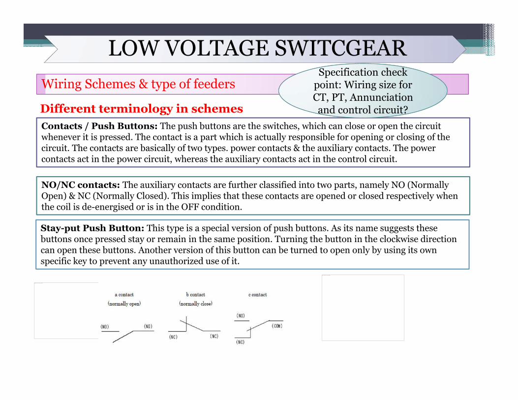
Different terminology in schemesContacts / Push Buttons: The push buttons are the switches, which can close or open the circuit whenever it is pressed. The contact is a part which is actually responsible for opening or closing of the circuit. The contacts are basically of two types. power contacts & the auxiliary contacts. The power contacts act in the power circuit, whereas the auxiliary contacts act in the control circuit.
NO/NC contacts: The auxiliary contacts are further classified into two parts, namely NO (Normally Open) & NC (Normally Closed). This implies that these contacts are opened or closed respectively when the coil is de-energised or is in the OFF condition.
Stay-put Push Button: This type is a special version of push buttons. As its name suggests these buttons once pressed stay or remain in the same position. Turning the button in the clockwise direction can open these buttons. Another version of this button can be turned to open only by using its own specific key to prevent any unauthorized use of it.
This image cannot currently be displayed.
This image cannot currently be displayed.
Specification check
and control circuit?
Specification check point: Wiring size for CT, PT, Annunciation and control circuit?

LOW VOLTAGE SWITCGEARWiring Schemes & type of feeders
Different terminology in schemesInterposing relay: In auto mode, only the auto start command (coming from central control room through PLC/DCS, etc.) will be able to start the motor. In such cases, the contact coming in the circuit should be capable to carry the pick-up current of the power contactor coil. This needs special attention since the contact comes from an electronic circuit. In case the contact is not rated for that much current, we have to use an auxiliary relay to multiply this command. The contact of the auxiliary relay is then used in the circuit of the power contactor coil. The auxiliary relay in such cases is known as Interposing relay
LOW VOLTAGE SWITCGEARWiring Schemes & type of feeders
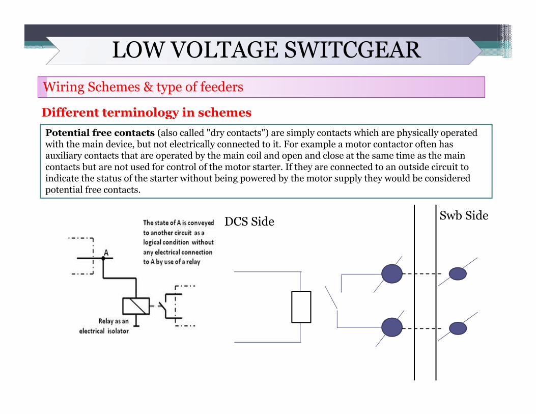
Different terminology in schemesPotential free contacts (also called "dry contacts") are simply contacts which are physically operated with the main device, but not electrically connected to it. For example a motor contactor often has auxiliary contacts that are operated by the main coil and open and close at the same time as the main contacts but are not used for control of the motor starter. If they are connected to an outside circuit to indicate the status of the starter without being powered by the motor supply they would be considered potential free contacts.
DCS Side Swb Side
LOW VOLTAGE SWITCGEARWiring Schemes & type of feeders
Different terminology in schemes
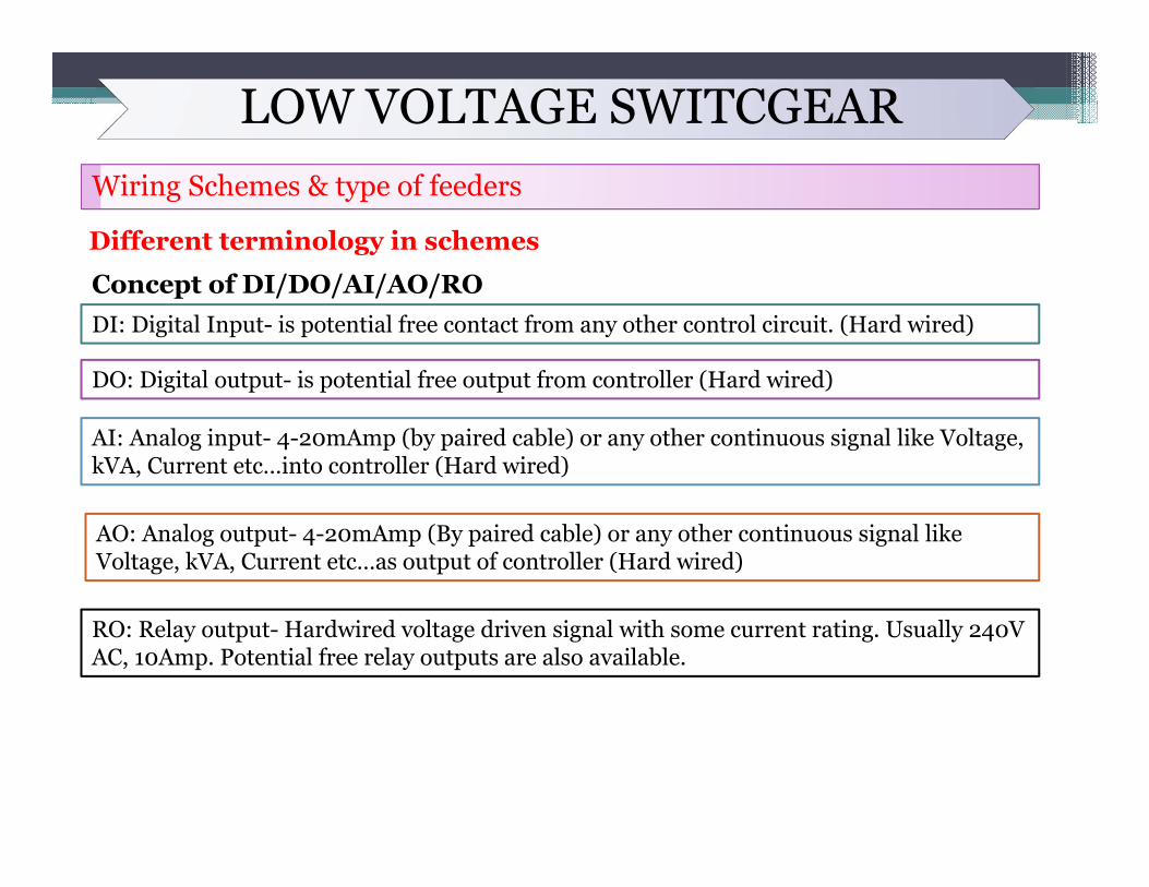
Concept of DI/DO/AI/AO/RO
What is Signal?
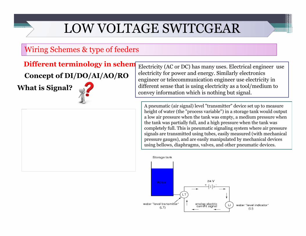
Electricity (AC or DC) has many uses. Electrical engineer use electricity for power and energy. Similarly electronics engineer or telecommunication engineer use electricity in different sense that is using electricity as a tool/medium to convey information which is nothing but signal.
A pneumatic (air signal) level "transmitter" device set up to measure height of water (the "process variable") in a storage tank would output a low air pressure when the tank was empty, a medium pressure when the tank was partially full, and a high pressure when the tank was completely full. This is pneumatic signaling system where air pressure signals are transmitted using tubes, easily measured (with mechanical pressure gauges), and are easily manipulated by mechanical devices using bellows, diaphragms, valves, and other pneumatic devices.
This image cannot currently be displayed.
LOW VOLTAGE SWITCGEARWiring Schemes & type of feeders
Different terminology in schemes
Concept of DI/DO/AI/AO/RODI: Digital Input- is potential free contact from any other control circuit. (Hard wired)
DO: Digital output- is potential free output from controller (Hard wired)
AI: Analog input- 4-20mAmp (by paired cable) or any other continuous signal like Voltage, kVA, Current etc…into controller (Hard wired)
AO: Analog output- 4-20mAmp (By paired cable) or any other continuous signal like Voltage, kVA, Current etc…as output of controller (Hard wired)
RO: Relay output- Hardwired voltage driven signal with some current rating. Usually 240V AC, 10Amp. Potential free relay outputs are also available.
LOW VOLTAGE SWITCGEARWiring Schemes & type of feeders
Basic Schemes 1: DOL Feeder
LOW VOLTAGE SWITCGEARWiring Schemes & type of feeders
Basic Schemes 2: DOL Feeder with local remote selection and remote start
This image cannot currently be displayed.
LOW VOLTAGE SWITCGEARWiring Schemes & type of feeders
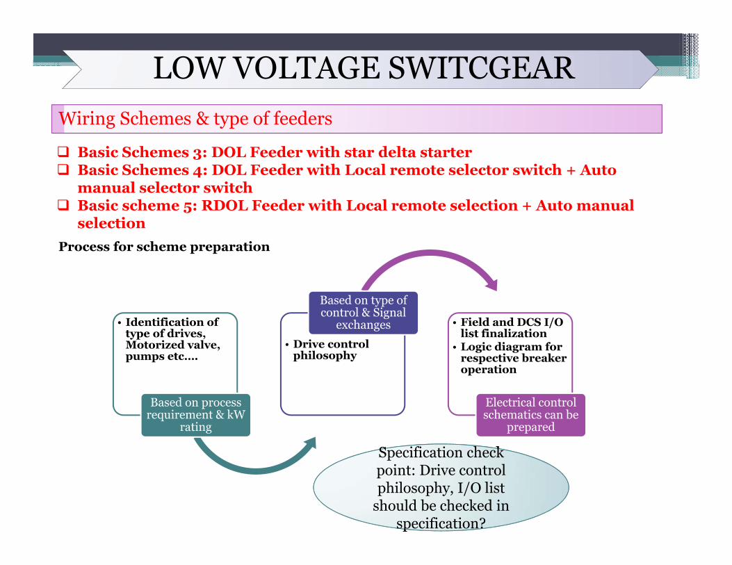
Basic Schemes 3: DOL Feeder with star delta starter Basic Schemes 4: DOL Feeder with Local remote selector switch + Auto
manual selector switch Basic scheme 5: RDOL Feeder with Local remote selection + Auto manual
selectionProcess for scheme preparation
• Identification of type of drives, Motorized valve, pumps etc….
Based on process requirement & kW
rating
• Drive control philosophy
Based on type of control & Signal
exchanges • Field and DCS I/O list finalization
• Logic diagram for respective breaker operation
Electrical control schematics can be
prepared
Specification check
specification?
Specification check point: Drive control philosophy, I/O list
should be checked in specification?
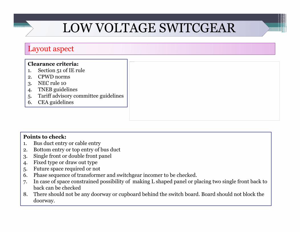
LOW VOLTAGE SWITCGEARLayout aspect
Clearance criteria: 1. Section 51 of IE rule2. CPWD norms3. NEC rule 104. TNEB guidelines5. Tariff advisory committee guidelines6. CEA guidelines
This image cannot currently be displayed.
Points to check: 1. Bus duct entry or cable entry2. Bottom entry or top entry of bus duct3. Single front or double front panel4. Fixed type or draw out type5. Future space required or not6. Phase sequence of transformer and switchgear incomer to be checked.7. In case of space constrained possibility of making L shaped panel or placing two single front back to
back can be checked8. There should not be any doorway or cupboard behind the switch board. Board should not block the
doorway.
LOW VOLTAGE CABLESSIZING CRITERIA
The following three criteria apply for the sizing of cables for circuit breaker controlled feeders:I. SHORT CIRCUIT CURRENT WITHSTAND CAPACITYThis criteria is applied to determine the minimum cross section area of the cable, so that cable can withstand the short circuit current.II. CONTINUOUS CURRENT CARRYING CAPACITYThis criteria is applied so that cross section of the cable can carry the required load current continuously at the designed ambient temperature and laying condition.III. STARTING AND RUNNING VOLTAGE DROPS IN CABLEThis criteria is applied to make sure that the cross sectional area of the cable is sufficient to keep the voltage drop (due to impedance of cable conductor) within the specified limit so that the equipment which is being supplied power through that cable gets at least the minimum required voltage at its power supply input terminal during starting and running condition both.
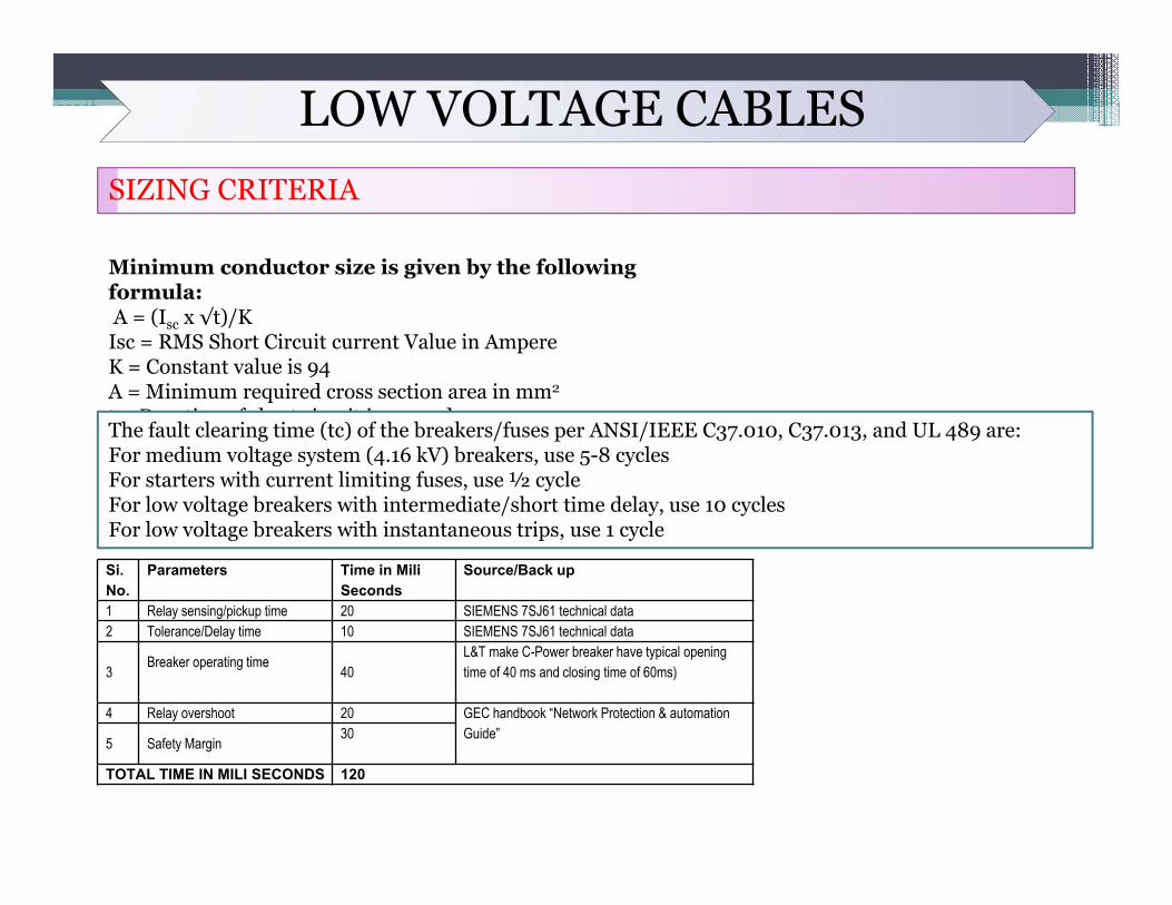
LOW VOLTAGE CABLESSIZING CRITERIA
Minimum conductor size is given by the following formula:A = (Isc x √t)/KIsc = RMS Short Circuit current Value in AmpereK = Constant value is 94A = Minimum required cross section area in mm2
t = Duration of short circuit in secondsThe fault clearing time (tc) of the breakers/fuses per ANSI/IEEE C37.010, C37.013, and UL 489 are:For medium voltage system (4.16 kV) breakers, use 5-8 cyclesFor starters with current limiting fuses, use ½ cycleFor low voltage breakers with intermediate/short time delay, use 10 cyclesFor low voltage breakers with instantaneous trips, use 1 cycle
Si. No.
Parameters Time in MiliSeconds
Source/Back up
1 Relay sensing/pickup time 20 SIEMENS 7SJ61 technical data2 Tolerance/Delay time 10 SIEMENS 7SJ61 technical data
3 Breaker operating time 40L&T make C-Power breaker have typical opening time of 40 ms and closing time of 60ms)
4 Relay overshoot 20 GEC handbook “Network Protection & automation Guide”5 Safety Margin 30
TOTAL TIME IN MILI SECONDS 120
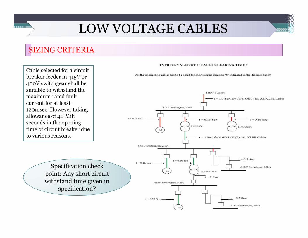
LOW VOLTAGE CABLESSIZING CRITERIA
Cable selected for a circuit breaker feeder in 415V or 400V switchgear shall be suitable to withstand the maximum rated fault current for at least 120msec. However taking allowance of 40 Miliseconds in the opening time of circuit breaker due to various reasons.
Specification check point: Any short circuit withstand time given in
specification?
LOW VOLTAGE CABLESSIZING CRITERIA
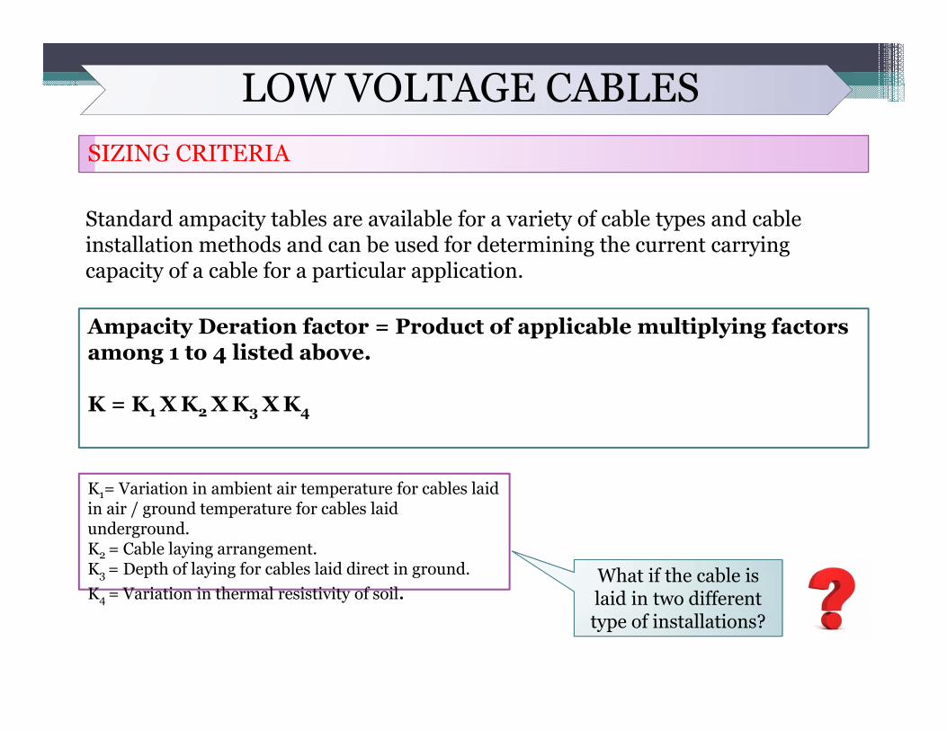
Standard ampacity tables are available for a variety of cable types and cable installation methods and can be used for determining the current carrying capacity of a cable for a particular application.
Ampacity Deration factor = Product of applicable multiplying factors among 1 to 4 listed above.
K = K1 X K2 X K3 X K4
K1= Variation in ambient air temperature for cables laid in air / ground temperature for cables laid underground.K2 = Cable laying arrangement.K3 = Depth of laying for cables laid direct in ground.K4 = Variation in thermal resistivity of soil.
What if the cable is laid in two different type of installations?
LOW VOLTAGE CABLESSIZING CRITERIA
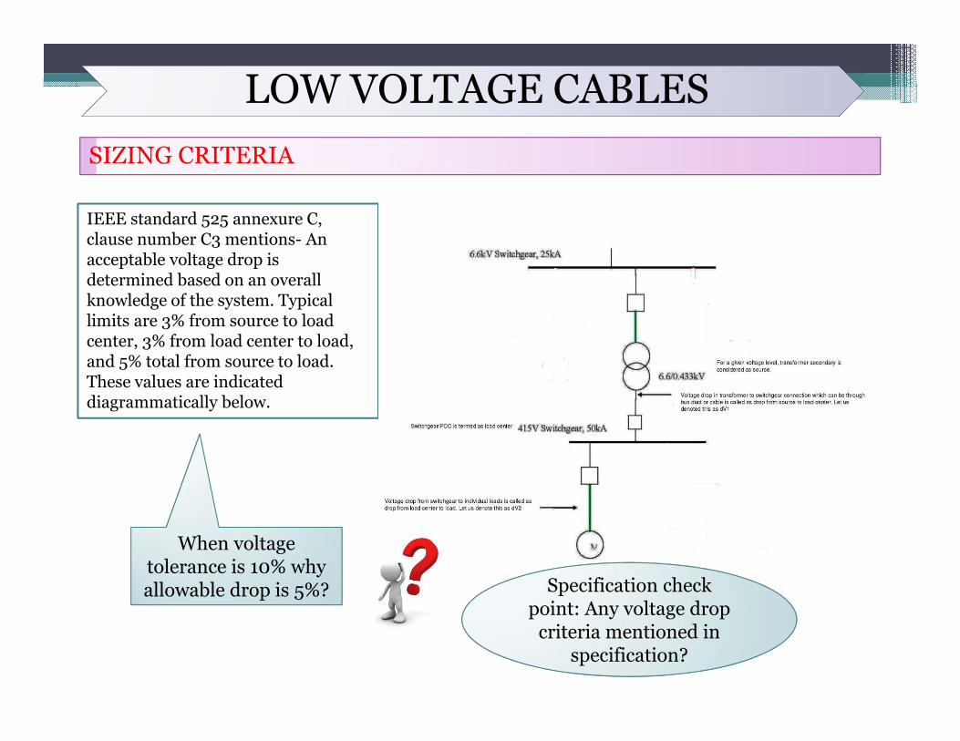
IEEE standard 525 annexure C, clause number C3 mentions- An acceptable voltage drop is determined based on an overall knowledge of the system. Typical limits are 3% from source to load center, 3% from load center to load, and 5% total from source to load. These values are indicated diagrammatically below.
When voltage tolerance is 10% why allowable drop is 5%? Specification check
point: Any voltage drop criteria mentioned in
specification?
LOW VOLTAGE CABLESSIZING CRITERIA
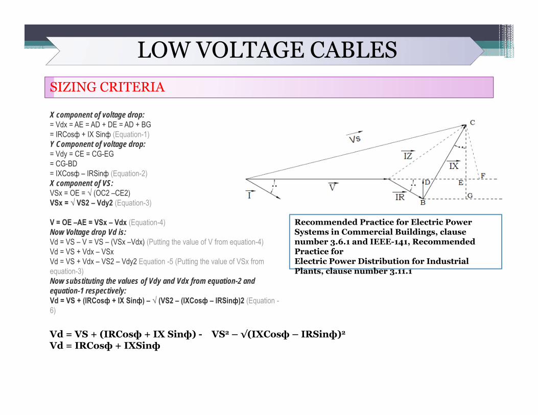
Vd = VS + (IRCosф + IX Sinф) - VS2 – √(IXCosф – IRSinф)2
Vd = IRCosф + IXSinф
Recommended Practice for Electric Power Systems in Commercial Buildings, clause number 3.6.1 and IEEE-141, Recommended Practice forElectric Power Distribution for Industrial Plants, clause number 3.11.1
X component of voltage drop:= Vdx = AE = AD + DE = AD + BG= IRCosф + IX Sinф (Equation-1)Y Component of voltage drop:= Vdy = CE = CG-EG= CG-BD= IXCosф – IRSinф (Equation-2)X component of VS:VSx = OE = √ (OC2 –CE2)VSx = √ VS2 – Vdy2 (Equation-3)
V = OE –AE = VSx – Vdx (Equation-4)Now Voltage drop Vd is:Vd = VS – V = VS – (VSx –Vdx) (Putting the value of V from equation-4)Vd = VS + Vdx – VSxVd = VS + Vdx – VS2 – Vdy2 Equation -5 (Putting the value of VSx from equation-3)Now substituting the values of Vdy and Vdx from equation-2 and equation-1 respectively:Vd = VS + (IRCosф + IX Sinф) – √ (VS2 – (IXCosф – IRSinф)2 (Equation -6)
THANK YOU