CSE 140 Lecture 12 Combinational Standard...
26
CSE 140 Lecture 12 Combinational Standard Modules CK Cheng CSE Dept. UC San Diego 1
-
Upload
nguyenphuc -
Category
Documents
-
view
228 -
download
2
Transcript of CSE 140 Lecture 12 Combinational Standard...

CSE 140 Lecture 12 Combinational Standard Modules
CK Cheng CSE Dept.
UC San Diego
1
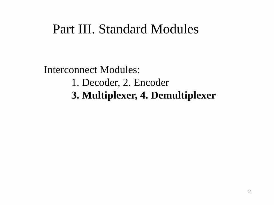
Part III. Standard Modules
Interconnect Modules: 1. Decoder, 2. Encoder 3. Multiplexer, 4. Demultiplexer
2
Multiplexer
• Definition • Logic Diagram • Application
3
4
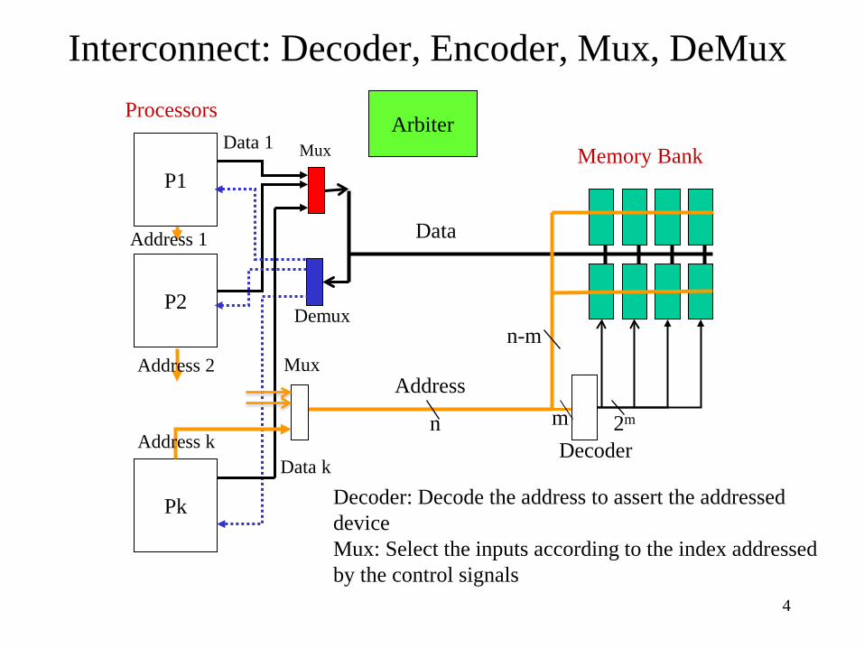
Interconnect: Decoder, Encoder, Mux, DeMux Processors
Decoder: Decode the address to assert the addressed device Mux: Select the inputs according to the index addressed by the control signals
P1 Memory Bank Mux
P2
Pk
Demux
Decoder
Mux
Data
Address
Address k
Address 2
Address 1
Data 1
Data k
Arbiter
n
n-m
m 2m
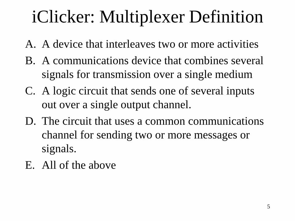
iClicker: Multiplexer Definition A. A device that interleaves two or more activities B. A communications device that combines several
signals for transmission over a single medium C. A logic circuit that sends one of several inputs
out over a single output channel. D. The circuit that uses a common communications
channel for sending two or more messages or signals.
E. All of the above
5
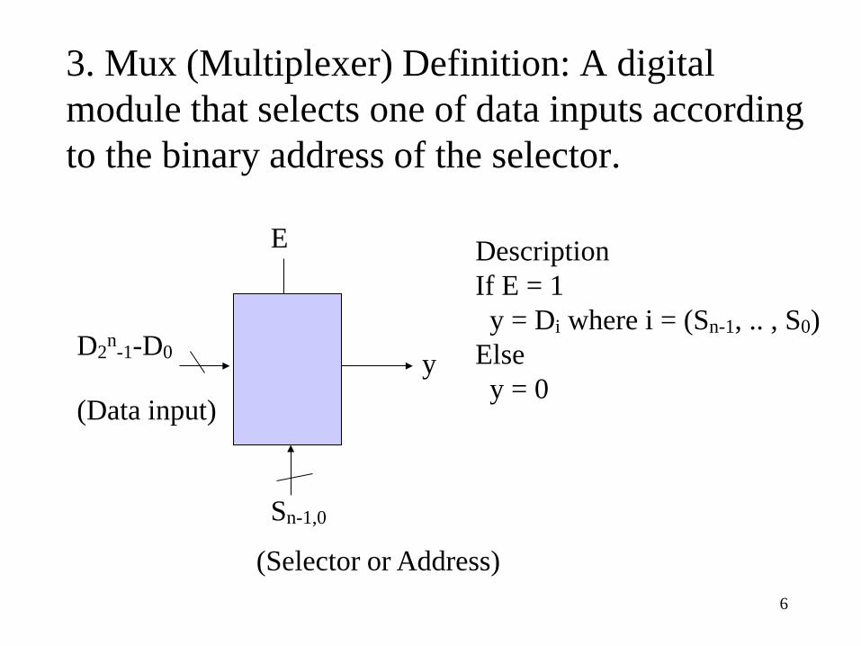
3. Mux (Multiplexer) Definition: A digital module that selects one of data inputs according to the binary address of the selector.
Description If E = 1 y = Di where i = (Sn-1, .. , S0) Else y = 0
E
y D2n-1-D0
(Data input)
Sn-1,0
(Selector or Address) 6
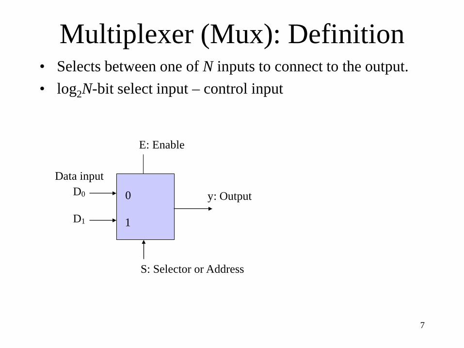
Multiplexer (Mux): Definition • Selects between one of N inputs to connect to the output. • log2N-bit select input – control input
7
E: Enable
y: Output
S: Selector or Address
D0
D1
0
1
Data input
8
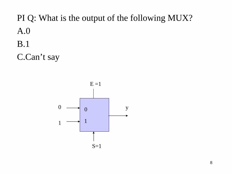
PI Q: What is the output of the following MUX? A.0 B.1 C.Can’t say
E =1
y
S=1
0
1
0
1
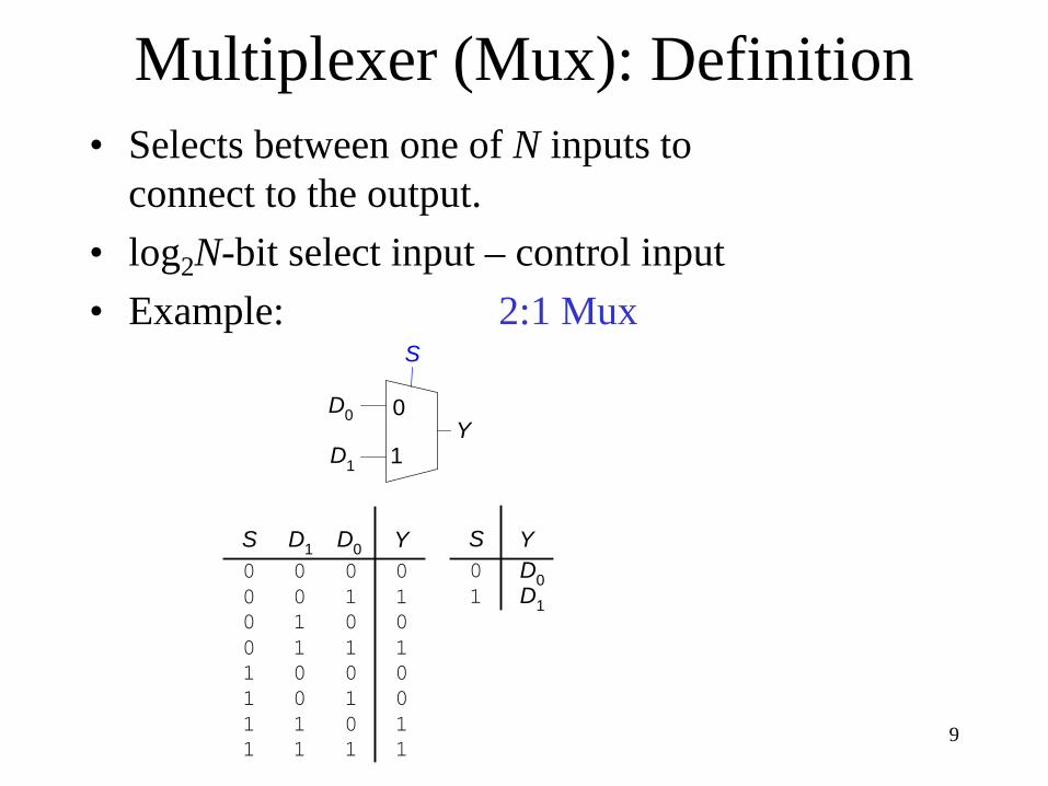
Multiplexer (Mux): Definition • Selects between one of N inputs to
connect to the output. • log2N-bit select input – control input • Example: 2:1 Mux
Y0 00 11 01 1
0101
0000
0 00 11 01 1
1111
0011
0
1
S
D0Y
D1
D1 D0S Y01 D1
D0
S
9
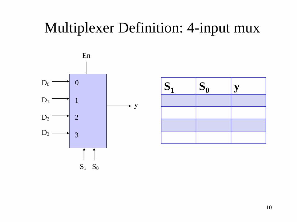
Multiplexer Definition: 4-input mux
En
y
S1 S0
D0
D1
D2
D3
0
1
2
3
10
S1 S0 y
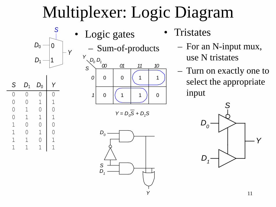
Multiplexer: Logic Diagram • Logic gates
– Sum-of-products
Y
D0
S
D1
D1
Y
D0
S
S 00 01
0
1
Y
11 10D0 D1
0
0
0
1
1
1
1
0
Y = D0S + D1S
• Tristates – For an N-input mux,
use N tristates – Turn on exactly one to
select the appropriate input
11
Y0 00 11 01 1
0101
0000
0 00 11 01 1
1111
0011
0
1
S
D0Y
D1
D1 D0S
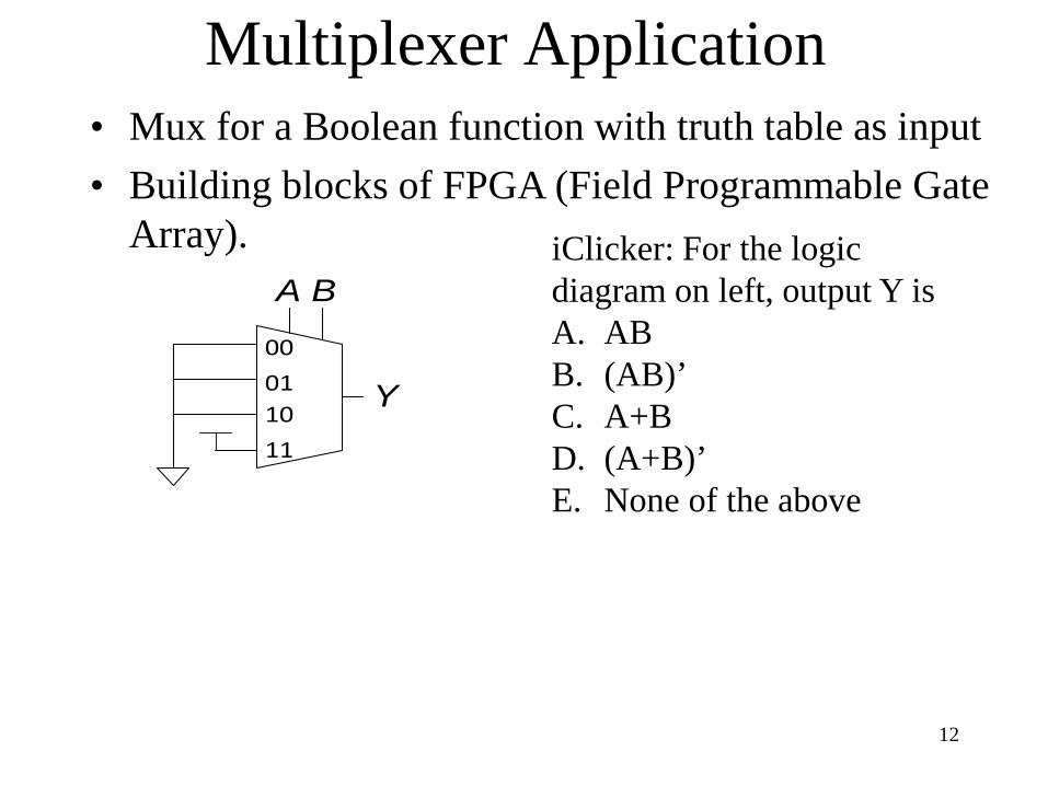
Multiplexer Application
00
Y011011
A B
• Mux for a Boolean function with truth table as input • Building blocks of FPGA (Field Programmable Gate
Array).
12
iClicker: For the logic diagram on left, output Y is A. AB B. (AB)’ C. A+B D. (A+B)’ E. None of the above
Multiplexer Application: universal set {Mux}
We use selector to decompose the function into smaller functions (less number of variables), which follows Shannon’s expansion. We simplify the decomposed functions using K-map, which follows consensus theorem.
13
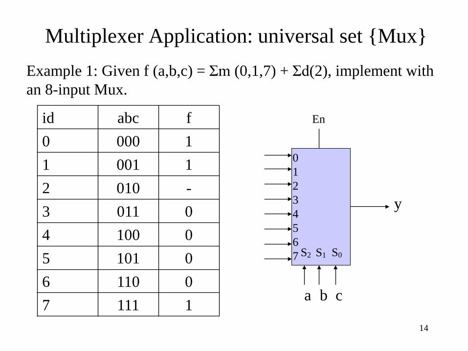
Multiplexer Application: universal set {Mux} Example 1: Given f (a,b,c) = Σm (0,1,7) + Σd(2), implement with an 8-input Mux.
14
En
y
a b c
S2 S1 S0
0 1 2 3 4 5 6 7
id abc f 0 000 1 1 001 1 2 010 - 3 011 0 4 100 0 5 101 0 6 110 0 7 111 1
E
y
a b
S1 S0
0
1
2
3
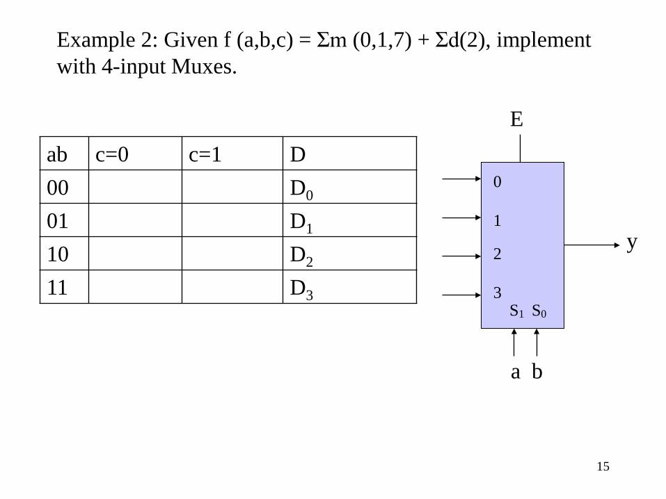
Example 2: Given f (a,b,c) = Σm (0,1,7) + Σd(2), implement with 4-input Muxes.
15
ab c=0 c=1 D 00 D0
01 D1
10 D2
11 D3
E
0
1
a
y
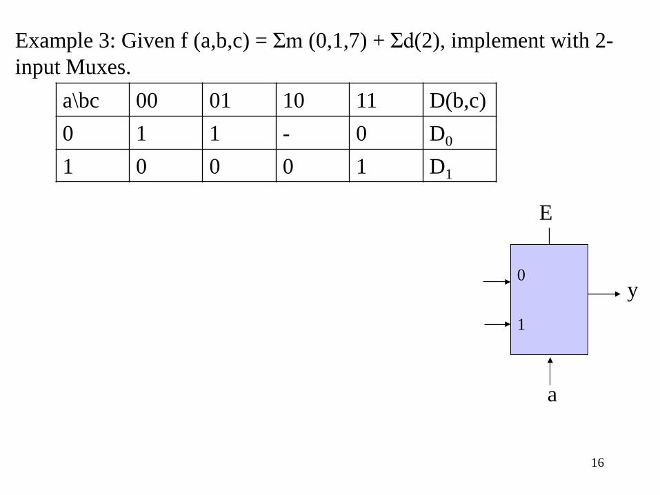
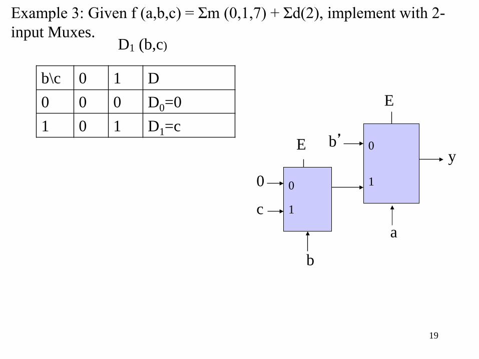
Example 3: Given f (a,b,c) = Σm (0,1,7) + Σd(2), implement with 2-input Muxes.
16
a\bc 00 01 10 11 D(b,c) 0 1 1 - 0 D0
1 0 0 0 1 D1
E
b’ 0
1
a
y
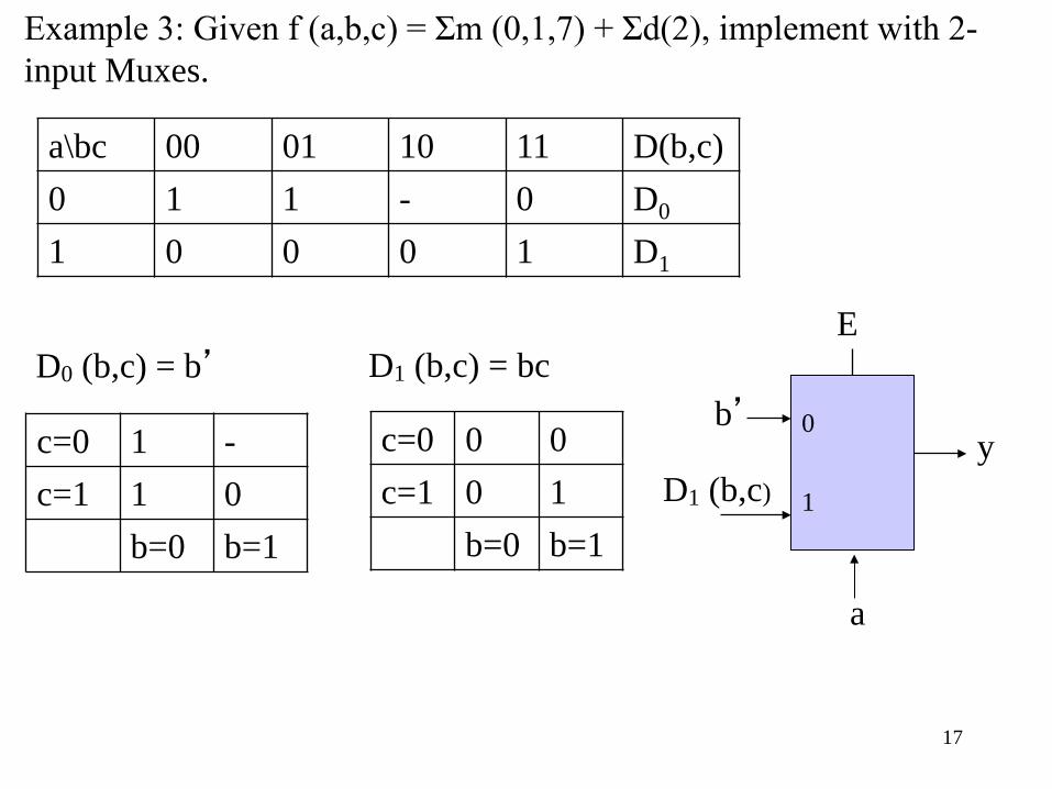
D0 (b,c) = b’ D1 (b,c) = bc
Example 3: Given f (a,b,c) = Σm (0,1,7) + Σd(2), implement with 2-input Muxes.
17
D1 (b,c)
a\bc 00 01 10 11 D(b,c) 0 1 1 - 0 D0
1 0 0 0 1 D1
c=0 1 - c=1 1 0
b=0 b=1
c=0 0 0 c=1 0 1
b=0 b=1
D1 (b,c)
E
b’ 0
1
a
y
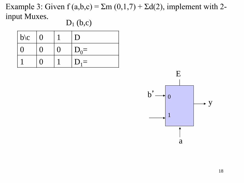
Example 3: Given f (a,b,c) = Σm (0,1,7) + Σd(2), implement with 2-input Muxes.
18
b\c 0 1 D 0 0 0 D0= 1 0 1 D1=
D1 (b,c)
E
E b’ 0
1
a
b
y
0
1
0
c
Example 3: Given f (a,b,c) = Σm (0,1,7) + Σd(2), implement with 2-input Muxes.
19
b\c 0 1 D 0 0 0 D0=0 1 0 1 D1=c
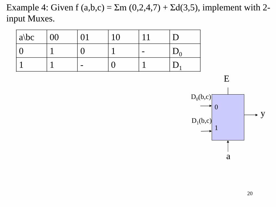
Example 4: Given f (a,b,c) = Σm (0,2,4,7) + Σd(3,5), implement with 2-input Muxes.
20
E
0
1
a
y
D0(b,c)
D1(b,c)
a\bc 00 01 10 11 D 0 1 0 1 - D0
1 1 - 0 1 D1
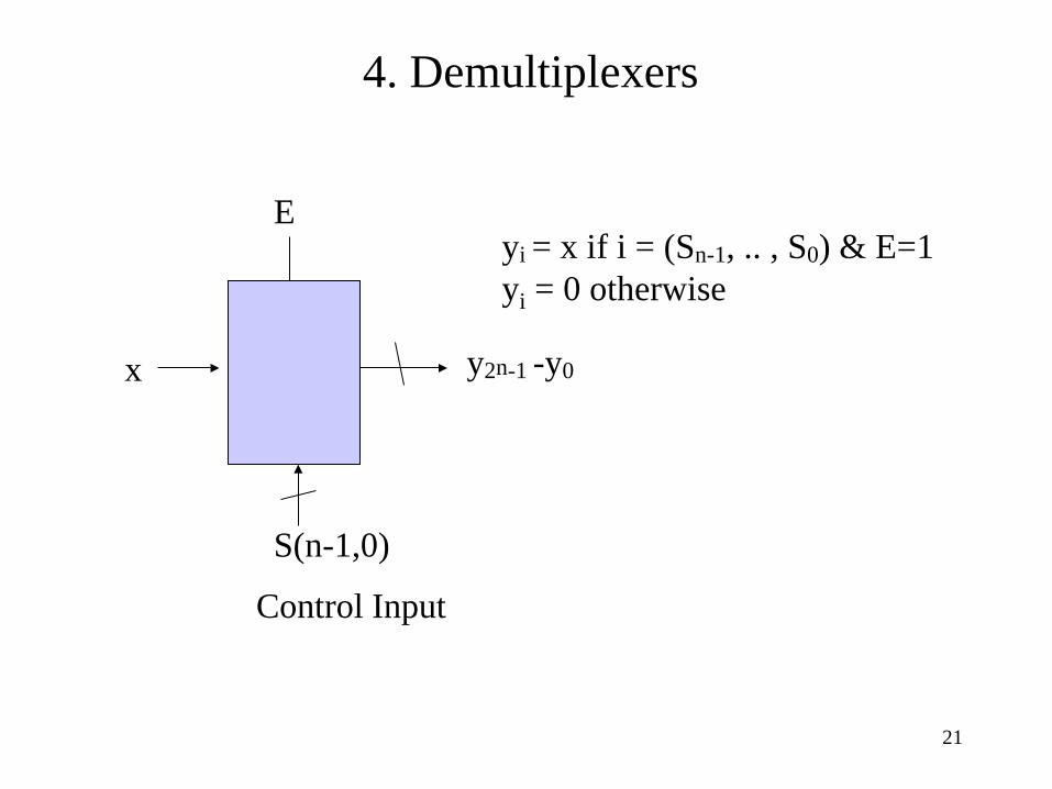
4. Demultiplexers
E
x y2n-1 -y0
S(n-1,0)
Control Input
yi = x if i = (Sn-1, .. , S0) & E=1 yi = 0 otherwise
21
22
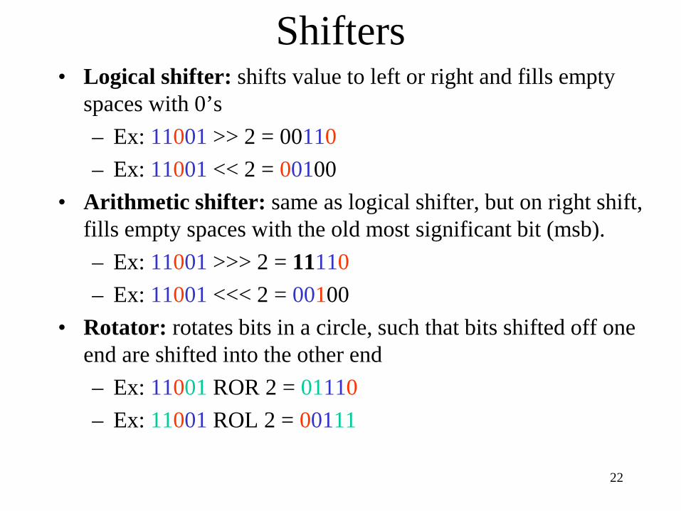
Shifters • Logical shifter: shifts value to left or right and fills empty
spaces with 0’s – Ex: 11001 >> 2 = 00110 – Ex: 11001 << 2 = 00100
• Arithmetic shifter: same as logical shifter, but on right shift, fills empty spaces with the old most significant bit (msb). – Ex: 11001 >>> 2 = 11110 – Ex: 11001 <<< 2 = 00100
• Rotator: rotates bits in a circle, such that bits shifted off one end are shifted into the other end – Ex: 11001 ROR 2 = 01110 – Ex: 11001 ROL 2 = 00111
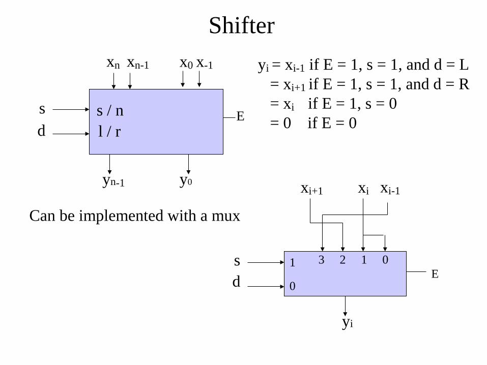
Shifter
Can be implemented with a mux
s d
yi
E 1
0
3 2 1 0
xi+1 xi-1 xi
s d
xn x0 x-1 xn-1
yn-1 y0
E s / n l / r
yi = xi-1 if E = 1, s = 1, and d = L = xi+1 if E = 1, s = 1, and d = R = xi if E = 1, s = 0 = 0 if E = 0
24
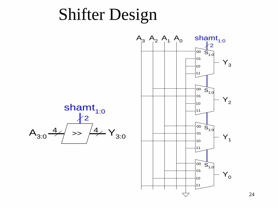
Shifter Design
A3:0 Y3:0
shamt1:0
>>
2
4 4
A3 A2 A1 A0
Y3
Y2
Y1
Y0
shamt1:0
00
01
10
11
S1:0
S1:0
S1:0
S1:0
00
01
10
11
00
01
10
11
00
01
10
11
2
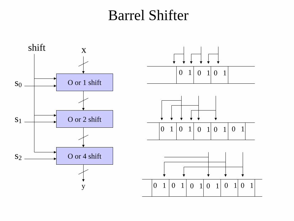
Barrel Shifter
O or 1 shift
O or 2 shift
O or 4 shift
x
s0
s1
s2
y
0 1 0 1 0 1
0 1 0 1 0 1 0 1 0 1
0 1 0 1 0 1 0 1 0 1 0 1
shift
26
Shifters as Multipliers and Dividers
• A left shift by N bits multiplies a number by 2N
– Ex: 00001 << 2 = 00100 (1 × 22 = 4) – Ex: 11101 << 2 = 10100 (-3 × 22 = -12)
• The arithmetic right shift by N divides a number by 2N
– Ex: 01000 >>> 2 = 00010 (8 ÷ 22 = 2) – Ex: 10000 >>> 2 = 11100 (-16 ÷ 22 = -4)