Graphics CSCI 201L Jeffrey Miller, Ph.D. HTTP :// WWW - SCF. USC. EDU /~ CSCI 201 USC CSCI 201L.

CSCI 5828: Foundations ofSoftware Engineering
Lecture 20, 21, and : Software DesignSlides created by Pfleeger and Atlee for the SE textbook
Some modifications to the original slides have been made by KenAnderson for clarity of presentation
03/20/2008 — 04/01/2008 — 04/08/2008
ISBN 0-13-146913-4Prentice-Hall, 2006
Chapter 5
Designingthe System
Copyright 2006 Pearson/Prentice Hall. All rights reserved.

Pfleeger and Atlee, Software Engineering: Theory and Practice Page 5.3© 2006 Pearson/Prentice Hall
Contents
5.1 What Is Design?5.2 Decomposition and Modularity5.3 Architectural Styles and Strategies5.4 Issues in Design Creation5.5 Characteristic of Good Design5.6Techniques for Improving Design5.7Design Evaluation and Validation5.8Documenting the Design5.9Information System Example5.10 Real Time Example5.11 What this Chapter Means for you

Pfleeger and Atlee, Software Engineering: Theory and Practice Page 5.4© 2006 Pearson/Prentice Hall
Chapter 5 Objectives
• Conceptual design and technical design• Design styles, techniques, and tools• Characteristic of good design• Validating designs• Documenting the design

Pfleeger and Atlee, Software Engineering: Theory and Practice Page 5.5© 2006 Pearson/Prentice Hall
5.1 What Is Design?
• Design is the creative process of transforming aproblem into a solution
• The description of a solution is also known as“the design”– The requirements specification defines a problem– The design document specifies a particular solution to
that problem

Pfleeger and Atlee, Software Engineering: Theory and Practice Page 5.6© 2006 Pearson/Prentice Hall
5.1 What Is Design?
• Design is a two-part interactive process– Conceptual design (system design)– Technical design

Pfleeger and Atlee, Software Engineering: Theory and Practice Page 5.7© 2006 Pearson/Prentice Hall
5.1 What Is Design?Conceptual Design
• Tells the customer what the system will do– Where will the data come from?– What will happen to the data in the system?– What will the system look like to users?– What choices will be offered to users?– What is the timing of events?– What will the reports and screens look like?
Pfleeger and Atlee, Software Engineering: Theory and Practice Page 5.8© 2006 Pearson/Prentice Hall
5.1 What Is Design?Conceptual Design (continued)
• Characteristics of good conceptual design– in customer’s language– no technical jargon– describes system functions– independent of implementation– linked to requirements
Pfleeger and Atlee, Software Engineering: Theory and Practice Page 5.9© 2006 Pearson/Prentice Hall
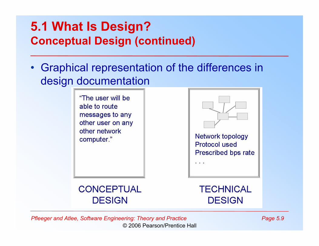
5.1 What Is Design?Conceptual Design (continued)
• Graphical representation of the differences indesign documentation
Pfleeger and Atlee, Software Engineering: Theory and Practice Page 5.10© 2006 Pearson/Prentice Hall
5.1 What Is Design?Technical Design
• Tells the programmers what the system will do– major hardware components and their function– hierarchy and functions of software components– data structures– data flow

Pfleeger and Atlee, Software Engineering: Theory and Practice Page 5.11© 2006 Pearson/Prentice Hall
5.2 Decomposition and ModularityFive Ways to Create Designs
• Modular decomposition• Data-oriented decomposition• Event-oriented decomposition• Outside-in design• Object-oriented design

Pfleeger and Atlee, Software Engineering: Theory and Practice Page 5.12© 2006 Pearson/Prentice Hall
5.2 Decomposition and ModularityLevels of Decomposition
• System data description• High level functional descriptions• Creating a hierarchy of information with increasing details

Pfleeger and Atlee, Software Engineering: Theory and Practice Page 5.13© 2006 Pearson/Prentice Hall
5.2 Decomposition and ModularityModularity
• Modules or components: composite parts ofdesign
• A system is modular when– each activity of the system is performed by exactly one
component– inputs and outputs of each component are well-defined
• all inputs to it are essential to its function• all outputs are produced by one of its actions

Pfleeger and Atlee, Software Engineering: Theory and Practice Page 5.14© 2006 Pearson/Prentice Hall
5.2 Decomposition and Modularity
• Graphical representation of the NIST/ECMA model for environmentintegration
– a software architect uses a high level design to explain generalcharacteristics without detail

Pfleeger and Atlee, Software Engineering: Theory and Practice Page 5.15© 2006 Pearson/Prentice Hall
5.3 Architectural Styles and StrategiesThree Design Levels
• Architecture: associates system componentswith capabilities
• Code design: specifies algorithms and datastructures for each component
• Executable design: lowest level of design,including memory allocation, data formats, bitpatterns

Pfleeger and Atlee, Software Engineering: Theory and Practice Page 5.16© 2006 Pearson/Prentice Hall
5.3 Architectural Styles and StrategiesDesign Styles
• Pipes and filters• Object-oriented design• Implicit invocation• Layering• Repositories• Interpreters• Process control• Client-server

Pfleeger and Atlee, Software Engineering: Theory and Practice Page 5.17© 2006 Pearson/Prentice Hall
5.3 Architectural Styles and StrategiesPipes and Filters
• The system has– Streams of data (pipe) for input and output– Transformation of the data (filter)
Pfleeger and Atlee, Software Engineering: Theory and Practice Page 5.18© 2006 Pearson/Prentice Hall
5.3 Architectural Styles and StrategiesPipes and Filters (continued)
• Several important properties– The designer can understand the entire system's effect
on input and output as the composition of the filters– The filters can be reused easily on other systems– System evolution is simple– Allow concurrent execution of filters
• Drawbacks– Encourages batch processing– Not good for handling interactive application– Duplication in filters’ functions

Pfleeger and Atlee, Software Engineering: Theory and Practice Page 5.19© 2006 Pearson/Prentice Hall
5.3 Architectural Styles and StrategiesObject-Oriented Design
• Must have two characteristics– the object must preserve the integrity of data
representation– the data representaion must be hidden from other
objects• easy to change the implementation without perturbing
the rest of the system
• One object must know the identity of other objectsin order to interact

Pfleeger and Atlee, Software Engineering: Theory and Practice Page 5.20© 2006 Pearson/Prentice Hall
5.3 Architectural Styles and StrategiesImplicit Invocation
• Event-driven, based on notation of broadcasting• Data exchange is through shared data in a repository• Applications
– packet-switch networks– databases to ensure consistency– user interfaces
• Useful for reusing design components from othersystem
• Disadvantage: lack of assurance that a componentwill respond to an event
Pfleeger and Atlee, Software Engineering: Theory and Practice Page 5.21© 2006 Pearson/Prentice Hall
5.3 Architectural Styles and StrategiesLayering
• Layers are hierarchical– Each layer provides service to the one outside it and acts as
a client to the layer inside it• The design includes protocols
– Explain how each pair of layers will interact• Advantages
– High levels of abstraction– Relatively easy to add and modify a layer
• Disadvantages– Not always easy to structure system layers– System performance may suffer from the extra coordination
among layers

Pfleeger and Atlee, Software Engineering: Theory and Practice Page 5.22© 2006 Pearson/Prentice Hall
5.3 Architectural Styles and StrategiesExample of Layering System
• A system to provide file security

Pfleeger and Atlee, Software Engineering: Theory and Practice Page 5.23© 2006 Pearson/Prentice Hall
5.3 Architectural Styles and StrategiesRepositories
• Two components– A central data store– A collection of components that operate on it to store,
retrieve, and update information• The challenge is deciding how the components
will interact– A traditional database: transactions trigger process
execution– A blackboard: the central store controls the triggering
process

Pfleeger and Atlee, Software Engineering: Theory and Practice Page 5.24© 2006 Pearson/Prentice Hall
5.3 Architectural Styles and StrategiesRepositories (continued)
• Major advantage: openness– Data representation is made available to various programmers (vendors)
so they can build tools to access the repository– But also a disadvantage: the data format must be acceptable to all
components

Pfleeger and Atlee, Software Engineering: Theory and Practice Page 5.25© 2006 Pearson/Prentice Hall
5.3 Architectural Styles and StrategiesInterpreters
• A virtual machine that “interprets” pseudocode ina way that makes it executable– Used not only to convert programming language, but
also to convert any kind of encoding to a more explicitform
• Composed of four components– A memory to contain pseudocode to be interpreted– An interpretation engine– The current state of the interpretation engine– The current state of the program being simulated

Pfleeger and Atlee, Software Engineering: Theory and Practice Page 5.26© 2006 Pearson/Prentice Hall
5.3 Architectural Styles and StrategiesExample of an Interpreter

Pfleeger and Atlee, Software Engineering: Theory and Practice Page 5.27© 2006 Pearson/Prentice Hall
5.3 Architectural Styles and StrategiesProcess Control
• Characterized by– the type of component– the relationships that hold among components
• Purpose: maintain specified properties of processoutputs at or near specified reference values calledset points
• Issues in designing a process control system– What variables to monitor– What sensor to use– How to calibrate them– How to deal with the timing of sensing and control

Pfleeger and Atlee, Software Engineering: Theory and Practice Page 5.28© 2006 Pearson/Prentice Hall
5.3 Architectural Styles and StrategiesProcess Control (continued)
• Software-based control system involves a closedloop in one of two forms, feedback andfeedforward as illustrated in the picture

Pfleeger and Atlee, Software Engineering: Theory and Practice Page 5.29© 2006 Pearson/Prentice Hall
5.3 Architectural Styles and StrategiesOther Styles
• Distributed system architecture: client-server– Advantage
• Users get information they need only when they need it– Disadvantage
• Need more sophisticated security, system management,and application development
• Domain-specific architecture– Take advantage of the commonalities afforded by the
application domain (e.g., avionics)• Heterogeneous architectures

Pfleeger and Atlee, Software Engineering: Theory and Practice Page 5.30© 2006 Pearson/Prentice Hall
5.3 Architectural Styles and StrategiesClient-Server
• Distributed systems usually described in terms of thetopology of their configuration.
• They can be organized as a ring or as a star as shown inthe picture
Pfleeger and Atlee, Software Engineering: Theory and Practice Page 5.31© 2006 Pearson/Prentice Hall
5.3 Architectural Styles and StrategiesSidebar 5.1 The World Cup Client-Server System
• Required both central control and distributedfunctions
• The system built included a central database forticket management, security, news service, andInternet link
• The server also calculated games statistics,provided historical information, securityphotographs, and clips of video action
• The clients ran on 1600 Sun workstations
Pfleeger and Atlee, Software Engineering: Theory and Practice Page 5.32© 2006 Pearson/Prentice Hall
5.4 Issues in Design Creation
• Modularity and levels of abstraction• Collaborative design• Designing the user interface• Concurrency• Design patterns and reuse
Pfleeger and Atlee, Software Engineering: Theory and Practice Page 5.33© 2006 Pearson/Prentice Hall
5.4 Issues in Design CreationModularity and Levels of Abstraction
• Levels of abstraction: the component at onelevel refines those in the level above, as wemove to lower levels, we find more detail abouteach component
• Information hiding: hide design decisions fromothers
• Modularity provides the flexibility– to understand the system– to trace the flow of data and function– to target the pockets of complexity

Pfleeger and Atlee, Software Engineering: Theory and Practice Page 5.34© 2006 Pearson/Prentice Hall
5.4 Issues in Design CreationSidebar 5.2 Using Abstraction
DO WHILE I is between 1 and (length of L)-1: Set LOW to index of smallest value in L(I), ..., L(length of L)
Interchange L(I) and L(LOW)END DO
DO WHILE I is between 1 and (length of L) - 1 Set LOW to current value of I DO WHILE J is between I+1 and (length of L) - 1: IF L(LOW) is greater than L(J) THEN set LOW to current value of J ENDIF ENDDO Set TEMP to L(LOW) S et L(LOW) to L(I) Set L(I) to TEMP ENDDO
Rearrange L in non-decreasing order

Pfleeger and Atlee, Software Engineering: Theory and Practice Page 5.35© 2006 Pearson/Prentice Hall
5.4 Issues in Design CreationCollaborative Design
• Most projects are collaborative work• Issues in collaborative design
– Who is the best suited to design each aspect of thesystem
– How to document the design– How to coordinate the design components
• Problems in performing collaborative design– Differences in personal experience, understanding,
and preference– People sometimes behave differently in groups from
the way they would behave individually

Pfleeger and Atlee, Software Engineering: Theory and Practice Page 5.36© 2006 Pearson/Prentice Hall
5.4 Issues in Design CreationCollaborative Design: Multi Sites Development
• Four stages– A project is performed at a single site with on-site developers
from foreign country– On-site analysts determine the system's requirements. Then the
requirements are provided to off-site's designers and developersgroups
– Off-site developers build generic products and components thatare used worlwide
– Off-site developers build products that take advantage of theirindividual expertise
• Issues– Languages– Communication paths

Pfleeger and Atlee, Software Engineering: Theory and Practice Page 5.37© 2006 Pearson/Prentice Hall
5.4 Issues in Design CreationSidebar 5.3 The Causes of Design Breakdown
• Lack of specialized design schemas• Lack of a meta-schema about the design process leading to poor
allocation of resources to the various design activities• Poor prioritization of issues leading to poor selection of alternative
solutions• Difficulty in considering all the stated or inferred constraints in
defining a solution• Difficulty in performing mental simulation with steps or test cases• Difficulty in keeping track and returning to subproblems whose
solution has been postponed• Difficulty in expanding or merging solutions from individual
subproblems to form a complete solution

Pfleeger and Atlee, Software Engineering: Theory and Practice Page 5.38© 2006 Pearson/Prentice Hall
5.4 Issues in Design CreationDesigning the User Interface
• Key elements to be addressed– Metaphors– A mental model– The navigation rules for the model– Look: characteristics of the system that convey
information to the user– Feel: interaction techniques
• Key issues to be considered– Cultural issues– User preferences

Pfleeger and Atlee, Software Engineering: Theory and Practice Page 5.39© 2006 Pearson/Prentice Hall
5.4 Issues in Design CreationGuidelines for Determining User-Interface Characteristics
• Consider design choices in terms of a design space• Each trade-off reflects at least two dimensions of the
choice• We can view the choices as
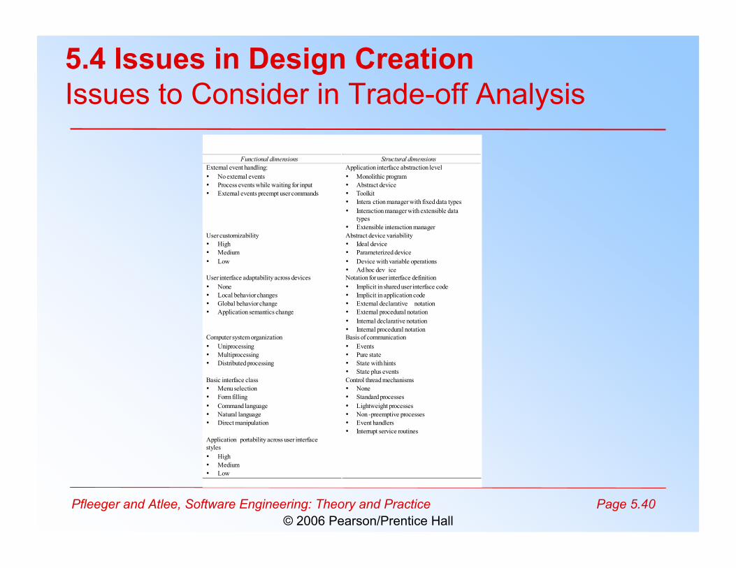
Pfleeger and Atlee, Software Engineering: Theory and Practice Page 5.40© 2006 Pearson/Prentice Hall
Functional dimensions Structural dimensions
External event handling:
• No external events
• Process events while waiting for input
• External events preempt user commands
Application interface abstraction level
• Monolithic program
• Abstract device
• Toolkit
• Intera ction manager with fixed data types
• Interaction manager with extensible data
types
• Extensible interaction manager
User customizability
• High
• Medium
• Low
Abstract device variability
• Ideal device
• Parameterized device
• Device with variable operations
• Ad hoc dev ice
User interface adaptability across devices
• None
• Local behavior changes
• Global behavior change
• Application semantics change
Notation for user interface definition
• Implicit in shared user interface code
• Implicit in application code
• External declarative notation
• External procedural notation
• Internal declarative notation
• Internal procedural notation
Computer system organization
• Uniprocessing
• Multiprocessing
• Distributed processing
Basis of communication
• Events
• Pure state
• State with hints
• State plus events
Basic interface class
• Menu selection
• Form filling
• Command language
• Natural language
• Direct manipulation
Control thread mechanisms
• None
• Standard processes
• Lightweight processes
• Non -preemptive processes
• Event handlers
• Interrupt service routines
Application portability across user interface
styles
• High
• Medium
• Low
5.4 Issues in Design CreationIssues to Consider in Trade-off Analysis

Pfleeger and Atlee, Software Engineering: Theory and Practice Page 5.41© 2006 Pearson/Prentice Hall
5.4 Issues in Design CreationConcurrency
• Problems– Consistency of data shared among components that
execute at the same time– Ensuring that one action does not interfere with another
• Solutions– Synchronization: method for allowing two activities to take
place concurrently without interfering with one another– Mutual exclusion: one process accessing a data element,
no other process can affect the element– Monitor: an abstract object that controls the mutual
exlusion of a particular process
Pfleeger and Atlee, Software Engineering: Theory and Practice Page 5.42© 2006 Pearson/Prentice Hall
5.4 Issues in Design CreationDesign Patterns and Reuse
• A design pattern names, abstracts, and identifiesthe key aspects of a common design structurethat make it useful for creating reusable design
• Key aspects– participating classes and instances– roles and collaborations– the distribution of responsibilities

Pfleeger and Atlee, Software Engineering: Theory and Practice Page 5.43© 2006 Pearson/Prentice Hall
5.5 Characteristics of Good Design
• Component independence– coupling– cohesion
• Exception identification and handling• Fault prevention and tolerance
– active– passive

Pfleeger and Atlee, Software Engineering: Theory and Practice Page 5.44© 2006 Pearson/Prentice Hall
5.5 Characteristics of Good DesignCoupling
• Highly coupled when there is a great deal of dependencies• Loosely coupled components have some dependency, but the
interconnections among components are weak• Uncoupled components have no interconnections at all
Pfleeger and Atlee, Software Engineering: Theory and Practice Page 5.45© 2006 Pearson/Prentice Hall
5.5 Characteristics of Good DesignCoupling (continued)
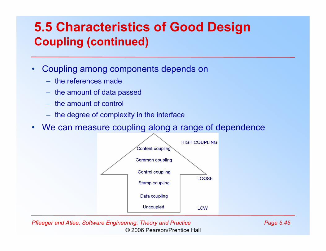
• Coupling among components depends on– the references made– the amount of data passed– the amount of control– the degree of complexity in the interface
• We can measure coupling along a range of dependence

Pfleeger and Atlee, Software Engineering: Theory and Practice Page 5.46© 2006 Pearson/Prentice Hall
5.5 Characteristics of Good DesignCoupling: Types of Coupling
• Content coupling• Common coupling• Control coupling• Stamp coupling• Data coupling

Pfleeger and Atlee, Software Engineering: Theory and Practice Page 5.47© 2006 Pearson/Prentice Hall
5.5 Characteristics of Good DesignContent Coupling
• Occurs when one component modifies an internal dataitem in another component, or when one componentbranches into the middle of another component

Pfleeger and Atlee, Software Engineering: Theory and Practice Page 5.48© 2006 Pearson/Prentice Hall
5.5 Characteristics of Good DesignCommon Coupling
• Making a change to the common data means tracing backto all components that access those data to evaluate theeffect of the change

Pfleeger and Atlee, Software Engineering: Theory and Practice Page 5.49© 2006 Pearson/Prentice Hall
5.5 Characteristics of Good DesignCohesion
• A component is cohesive if all elements of the component aredirected toward and essential for performing the same task
• Several forms of cohesion

Pfleeger and Atlee, Software Engineering: Theory and Practice Page 5.50© 2006 Pearson/Prentice Hall
5.5 Characteristics of Good DesignExample of Cohesion
Pfleeger and Atlee, Software Engineering: Theory and Practice Page 5.51© 2006 Pearson/Prentice Hall
5.5 Characteristics of Good DesignException Indentification and Handling
• Exceptions: situations that we know are counterto what we really want the system to do– failure to provide a service– providing the wrong service or data– corrupting data
• Exceptions can be handled in one of three ways– retry– correct– report

Pfleeger and Atlee, Software Engineering: Theory and Practice Page 5.52© 2006 Pearson/Prentice Hall
5.5 Characteristics of Good DesignSidebar 5.4 Control Issues• System 1 and 2 are two possible designs for the same system
– Fan-in is the number of components controlling particular design– fan-out is number or components controlled by a component
• Better design when it has low fan out

Pfleeger and Atlee, Software Engineering: Theory and Practice Page 5.53© 2006 Pearson/Prentice Hall
5.5 Characteristics of Good DesignFault Prevention and Tolerance
• Active fault detection: periodically check forsymptoms of faults, or try to anticipate whenfailure will occur
• Passive fault detection: wait until a failureoccurs during execution
• Fault correction: the system's compensationfor a fault's presence
• Fault tolerance: the isolation of damagecaused by a fault

Pfleeger and Atlee, Software Engineering: Theory and Practice Page 5.54© 2006 Pearson/Prentice Hall
5.5 Characteristics of Good DesignSidebar 5.5 The Need for Safe Design
• From 1986 to 1997 there were over 450 reports filed with U.SFood and Drug Administration, detailing software defects inmedical devices, 24 of which led to death or injury
• Leveson and Turner describe in great detail the user-interfacedesign probem that led to at least three deaths and severalinjuries from a malfunctioning radiation therapy machine
• June 1997, new federal regulations authorized the FDA toexamine the software design of medical devices
• Software designers must see directly how their products will beused, rather than rely on salespeople and marketers

Pfleeger and Atlee, Software Engineering: Theory and Practice Page 5.55© 2006 Pearson/Prentice Hall
5.6 Techniques for Improving Design
• Reducing complexity• Design by contract• Prototyping design• Fault-tree analysis

Pfleeger and Atlee, Software Engineering: Theory and Practice Page 5.56© 2006 Pearson/Prentice Hall
5.6 Techniques for Improving DesignReducing Complexity
• Look for ways to reduce the complexity ofdiagrams– e.g. reduce “crossovers”– even better: simplify the diagram by finding structure
that are not “pulling their own weight”• reassign their responsibilities and eliminate
• “It seems that perfection is reached not whenthere is nothing left to add, but when there isnothing left to take away.” — Antoine de Saint-Exupéry, Terre des hommes, 1939

Pfleeger and Atlee, Software Engineering: Theory and Practice Page 5.57© 2006 Pearson/Prentice Hall
5.6 Techniques for Improving DesignDesign by Contract
• Suggested by Meyer to ensure that a designmeets its specifications (contracts)
• Meyer applies the notion of contract to software– A client: a software component– Supplier: perform subtask requested by a client– Precondition: mutual obligation– Postcondition: benefits– Invariant: consistency constraint– Assertions: contract properties

Pfleeger and Atlee, Software Engineering: Theory and Practice Page 5.58© 2006 Pearson/Prentice Hall
5.6 Techniques for Improving DesignExample of Design by Contract
• Suppose the client component has a table where eachelement is identified by a character string used as a key
• Supplier's component's task is to insert an element from thetable to the dictionary.
• The formalized contract in the object oriented languageput (x: ELEMENT; key: STRING) is -- insert x so that it will be retrievable through key. require count <= capacity; not key.empty do … Some insertion algorithm… ensure has (x); item (key) = (x); count = old count + 1 end

Pfleeger and Atlee, Software Engineering: Theory and Practice Page 5.59© 2006 Pearson/Prentice Hall
5.6 Techniques for Improving DesignExample of Design by Contract
• Meyer’s implementation of Design by Contract is“heavyweight”– preconditions, postconditions, and invariants in Eiffel are part of
the syntax• required for each method you create!
• A lightweight approach is to use your programminglanguages assertion mechanism– Typically as simple as
• assert (boolean condition)• If the condition is false, an exception is thrown
– An assertion at the start of method is a pre-condition, andassertion at the end is a post-condition
• Class invariants are harder to achieve with this method
Pfleeger and Atlee, Software Engineering: Theory and Practice Page 5.60© 2006 Pearson/Prentice Hall
5.6 Techniques for Improving DesignPrototyping Design
• Same advantages provided during design stage• A feasibility prototype can explore whether the
proposed solution will actually solve the problem– Such prototypes are often “throwaways”
• But not always, sometime parts of a prototypecan be saved to be used in the actual system– In this situation, since you have a design in hand, the
prototype can be built to match the design and then“evolved” into the production system

Pfleeger and Atlee, Software Engineering: Theory and Practice Page 5.61© 2006 Pearson/Prentice Hall
5.6 Techniques for Improving DesignFault-tree Analysis: Steps
• Identifying possible failures• Building a graph
– Nodes are failures, either of single components,system functions, or the entire system
– Edges indicate the relationships among nodes• Searching for several types of design weakness
– single point of failure– uncertainty– ambiguity– missing components

Pfleeger and Atlee, Software Engineering: Theory and Practice Page 5.62© 2006 Pearson/Prentice Hall
5.6 Techniques for Improving DesignGuidewords for Identifying Possible Failures
Guideword Interpretation
no more less part of other than early late before after
No data or control signal was sent or received The volume of data is too much or too fast The volume of data is too low or too slow The data or control signal is incomplete The data or control signal has another component The signal arrives too early for the clock The signal arrives too late for the clock The signal arrives too early in the expected sequence The signal arrives too late in the expected sequence

Pfleeger and Atlee, Software Engineering: Theory and Practice Page 5.63© 2006 Pearson/Prentice Hall
5.6 Techniques for Improving DesignFault-tree Analysis: An Example
• Portion of power plant control system• From this fault tree we can construct another tree, known as a
cut-set tree

Pfleeger and Atlee, Software Engineering: Theory and Practice Page 5.64© 2006 Pearson/Prentice Hall
5.6 Techniques for Improving DesignFault-tree Analysis: Example (continued)
• Cut-set tree generated from the fault tree of a portion of thepower plant control system

Pfleeger and Atlee, Software Engineering: Theory and Practice Page 5.65© 2006 Pearson/Prentice Hall
5.6 Techniques for Improving DesignFault-tree Analysis: Example (continued)
• The leaf-nodes in the cut-set identify events thatcan lead to the failure of the system– We then examine the design, assume a failure has
occurred and see if we can find a set of events that willproduce it;
– Note: this is different from the original fault tree, whichis constructed by asking how a failure can occur, notwhether the current design will cause that failure
– If we conclude that the failure can occur with thepresent design, then we have to work to remove and/ormitigate the identified fault

Pfleeger and Atlee, Software Engineering: Theory and Practice Page 5.66© 2006 Pearson/Prentice Hall
5.7 Design Evaluation and Validation
• Mathematical validation• Measuring design quality• Comparing designs
– one specification, many designs– comparison table
• Design reviews

Pfleeger and Atlee, Software Engineering: Theory and Practice Page 5.67© 2006 Pearson/Prentice Hall
5.7 Design Evaluation and ValidationMathematical Validation
• Break the system into a set of processes– A set of inputs– A set of expected outputs– A set of assertions about the process
• For each process, we demonstrate– If the set of inputs is formulated correctly, it is
transformed properly into the set of expected output– The process terminates without failure
• This procedure “proves” that the design iscorrect

Pfleeger and Atlee, Software Engineering: Theory and Practice Page 5.68© 2006 Pearson/Prentice Hall
5.7 Design Evaluation and ValidationMeasuring Design Quality
• Proposed measurements to assess certain keyaspects of design quality– Measures of cohesion for OO design Measures high-
level design, including cohesion and coupling• Complexity involves two aspects
– Complexity within each component– The complexity of the relationships among the
components

Pfleeger and Atlee, Software Engineering: Theory and Practice Page 5.69© 2006 Pearson/Prentice Hall
5.7 Design Evaluation and ValidationCard and Glass's Measure of Complexity
• C = S + D• where
– S = (1/n ) Σ f 2(i )– D = V (i )/[f (i ) + 1]
• S = the structural complexity (between comps)• D = the data complexity (within components)• f (i ) = the fan-out of component i• V (i ) = the number of input and output variables in
component i• n = the number of components

Pfleeger and Atlee, Software Engineering: Theory and Practice Page 5.70© 2006 Pearson/Prentice Hall
5.7 Design Evaluation and ValidationSystem's Complexity vs. Number of Faults
• Fault rate graphed against system design complexity– Each increase of one unit of complexity increased the fault rate by
0.4 faults per thousand lines of code

Pfleeger and Atlee, Software Engineering: Theory and Practice Page 5.71© 2006 Pearson/Prentice Hall
5.7 Design Evaluation and ValidationComparing Designs
• One specification, many designs: to see howdifferent designs can be used to solve the sameproblem
• Example– Shaw and Garland present four different architectural
designs to implement KWIC (key word in context)• shared data• abstract data type• implicit invocation• pipe and filter

Pfleeger and Atlee, Software Engineering: Theory and Practice Page 5.72© 2006 Pearson/Prentice Hall
5.7 Design Evaluation and ValidationShared Data Solution for KWIC
• The problem is broken into its four functional parts: input,circular shift, alphabetize, and output

Pfleeger and Atlee, Software Engineering: Theory and Practice Page 5.73© 2006 Pearson/Prentice Hall
5.7 Design Evaluation and ValidationAbstract Data Type Solution for KWIC
• Data is no longer centrally stored and shared, but thedecomposition process is the same
Pfleeger and Atlee, Software Engineering: Theory and Practice Page 5.74© 2006 Pearson/Prentice Hall
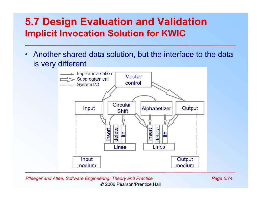
5.7 Design Evaluation and ValidationImplicit Invocation Solution for KWIC
• Another shared data solution, but the interface to the datais very different

Pfleeger and Atlee, Software Engineering: Theory and Practice Page 5.75© 2006 Pearson/Prentice Hall
5.7 Design Evaluation and ValidationPipe-and-Filter Solution for KWIC
• The sequence of processing is controlled by the sequenceof filters

Pfleeger and Atlee, Software Engineering: Theory and Practice Page 5.76© 2006 Pearson/Prentice Hall
5.7 Design Evaluation and ValidationShaw and Garland’s Comparison
Attribute Shared
data
Abstract
data type
Implicit
invocation
Pipe and filter
Easy to change algorithm - - + +
Easy to change data representation - + - - Easy to change function + - + +
Good performance + + - -
Easy to reuse - + - +

Pfleeger and Atlee, Software Engineering: Theory and Practice Page 5.77© 2006 Pearson/Prentice Hall
Attribute Priority Shared
data
Abstract data
type
Implicit
invocation
Pipe and filter
Easy to
change
algorithm
1 1 2 4 5
Easy to change data
representation
4 1 5 2 1
Easy to
change
function
3 4 1 4 5
Good performance
3 5 4 2 2
Easy to reuse 5 1 4 2 5
5.7 Design Evaluation and ValidationComparison Tables (continued)
• Weighted comparison of Shaw and Garlanddesign

Pfleeger and Atlee, Software Engineering: Theory and Practice Page 5.78© 2006 Pearson/Prentice Hall
5.7 Design Evaluation and ValidationComparison Tables (continued)
• With the previous table, we can then assign aweighted score to each design– Sum(priority(i) x design(i)) where i represents ith att– Shared Data design is– 1x1 + 4x1 + 3x4 + 3x5 + 5x1 = 37
• You compute a value for each design and choosethe design with the highest value– This is a subjective technique, since attributes,
priorities, and design values are all assigned by aproject’s managers/designers
Pfleeger and Atlee, Software Engineering: Theory and Practice Page 5.79© 2006 Pearson/Prentice Hall
5.7 Design Evaluation and ValidationDesign Reviews
• Preliminary design review– examines conceptual design with customer and users
• Critical design review– presents technical design to developers
• Program design review– programmers get feedback on their designs before
implementation

Pfleeger and Atlee, Software Engineering: Theory and Practice Page 5.80© 2006 Pearson/Prentice Hall
5.7 Design Evaluation and ValidationQuestions for any Design Review
• Is it a solution to the problem?• Is it modular, well-structured, and easy to understand?• Can we improve the structure and understandability?• Is it portable to other platforms?• Is it reusable?• Is it easy to modify or expand?• Does it support ease of testing?• Does it maximize performance, where appropriate?• Does it reuse components from other projects, where appropriate?• Are the algorithms appropriate, or can they be improved?• If this system is to have a phased development, are the phases interfaced sufficiently
so that there is an easy transition from one phase to the next?• Is it well-documented, including design choices and rationale?• Does it cross-reference the components and data with the requirements?• Does it use appropriate techniques for handling faults and preventing failures?

Pfleeger and Atlee, Software Engineering: Theory and Practice Page 5.81© 2006 Pearson/Prentice Hall
5.8 Documenting the DesignDocument Contains
• Design rationale– Outlining the critical issues and trade-offs
• especially with respect to non-functional issues
• Descriptions of the system’s component• A section that addresses how the user interacts with
the system• A set of diagrams or formal notations that describes
the overall organization and structure of the system• If our system is distributed, then we also include a
topology of the system’s network

Pfleeger and Atlee, Software Engineering: Theory and Practice Page 5.82© 2006 Pearson/Prentice Hall
5.8 Documenting the DesignSection for How Users Interact with the System
• menus and other display-screen formats• human interfaces: function keys, touch screen
descriptions, keyboard layouts, use of a mouse or joystick• report formats• input: where data come from, how they are formatted, on
what media they are stored• output: where data are sent, how they are formatted, on
what media they are stored• general functional characteristics• performance constraints• archival procedures• fault-handling approach

Pfleeger and Atlee, Software Engineering: Theory and Practice Page 5.83© 2006 Pearson/Prentice Hall
5.9 Information System ExamplePicadilly System
• Using a combination of techniques fordocumenting the design
• A system for tracking opposition schedule: dataflow and the data model

Pfleeger and Atlee, Software Engineering: Theory and Practice Page 5.84© 2006 Pearson/Prentice Hall
5.9 Information System ExamplePicadilly System Data Dictionary
Opposition schedule = * Data flow * Television company name + {Opposition transmission date + Opposition transmission time + Opposition program name + (Opposition predicted rating)}
Input: Opposition schedule For each Television company name , create Opposition company . For each Opposition schedule , Locate the Episode where Episode schedule date = Opposition transmission date AND Episode start time = Opposition transmission time Create instance of Opposition program Create the relationships Planning and Competing Output: List of Opposition programs

© 2008, University of Colorado
Ariane 5 Disaster On June 4, 1996, after 7 billion dollars of development, an unmanned
Ariane 5 rocket exploded just forty seconds after lift-off The rocket and its cargo were valued at $500 million for a total cost of 7.5
billion dollars! The error was traced to a software component in the Inertial Reference
System that had been reused from the Ariane 4 flight software The reused component was more than 10 years old and had flown
successfully on numerous Ariane 4 flights The problem => certain assumptions changed between the Ariane 4 and the
Ariane 5 and the software was not updated in response

© 2008, University of Colorado
Ariane 5, background info The flight software was written in Ada
which has a first class exceptionconstruct (it predates C++ and Java in this regard)
If an exception is thrown but not caught,the error will “percolate” up through thecall stack and will eventually terminatethe entire system
© 2008, University of Colorado
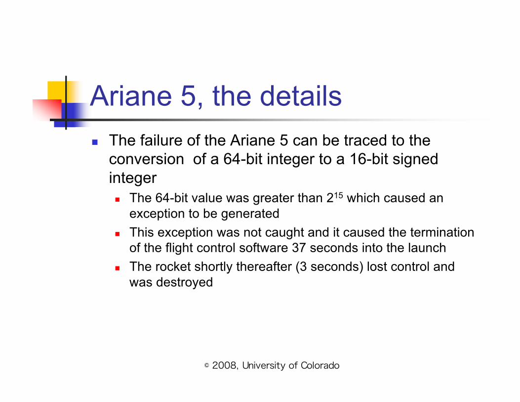
Ariane 5, the details The failure of the Ariane 5 can be traced to the
conversion of a 64-bit integer to a 16-bit signedinteger The 64-bit value was greater than 215 which caused an
exception to be generated This exception was not caught and it caused the termination
of the flight control software 37 seconds into the launch The rocket shortly thereafter (3 seconds) lost control and
was destroyed

© 2008, University of Colorado
More information Jean-Marc Jézéquel and Bertrand Meyer wrote a paper that
traces the problem to an inappropriate reuse of a 10-year oldsoftware component They reveal that one “vexing” aspect of this disaster is that the error
occurred in a software system that was not needed during launch! The calculation was supposed to be stopped 9 seconds before
launch, but the inertial reference system had been reset duringa hold in the countdown and its initialization sequenceproceeded during launch.
This is what caused the rocket to veer off course… theinitialization sequence was sending random sequences of1s and 0s to the flight control software, which wasinterpreting them as commands to fire various sets ofbooster jets in completely random patterns!

© 2008, University of Colorado
Details, continued Their paper reveals that sufficient software dev. processes were
in place and the system that caused the error had even been reviewedextensively before launch
exception handlers had been placed around 4 of 7 variables;unfortunately, the data conversion error occurred in one of the3 unprotected variables
why leave 3 variables unprotected? Performance! If you addexception handling code, you slow the performance of thesystem
plus, the developers had an analysis that showed that overflowcould not occur with the 3 unprotected variables
so they had good reason to leave them unprotected
© 2008, University of Colorado
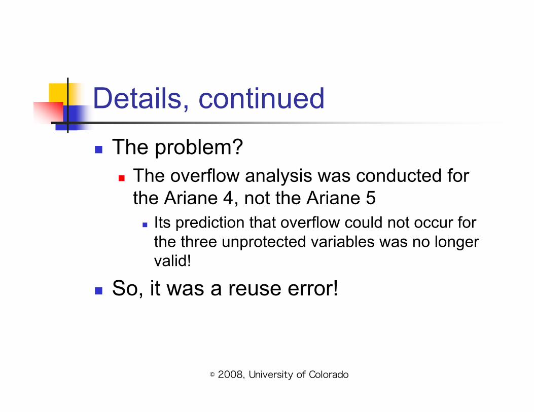
Details, continued The problem?
The overflow analysis was conducted forthe Ariane 4, not the Ariane 5
Its prediction that overflow could not occur forthe three unprotected variables was no longervalid!
So, it was a reuse error!

© 2008, University of Colorado
Ariane 5, summary The authors conclude that “Design by Contract” was needed in
this situation In particular, the component needed to specify a “contract” with its
users; one aspect of this contract is specifying the legal inputvalues
If the component had done something similar to an assert constructlike this
proc foo(actual_value: int) assert(actual_value <= maximum_value)
The authors argue that the error may well have been detectedduring system test; they further argue that such “contracts” shouldbe a first-class, required programming language construct; not anoptional construct that few use

Pfleeger and Atlee, Software Engineering: Theory and Practice Page 5.92© 2006 Pearson/Prentice Hall
5.10 Real System exampleAriane-5 Failure
• Jesequel and Meyer suggest that design by contract mighthave caught the Ariane-5
– There was no precise specification for the component reuse from Ariane-4
• The code did not check the condition to check the variablerepresenting horizontal bias that fit in 16 bits
• Had this condition been made explicit, it might have looked like
convert (horizontal_bias : DOUBLE): INTEGER is require horizontal_bias <= Maximum_bias do …… ensure ……
end

Pfleeger and Atlee, Software Engineering: Theory and Practice Page 5.93© 2006 Pearson/Prentice Hall
5.11 What This Chapter Means for you
• Looked at what it means to design a system• Design begins at a high level, with important decisions
about system architecture based on– system requirements– desirable attributes– the long-term intended use of the system
• Need to keep in mind the several characteristics as webuild a design– Modularity and level of abstraction– Coupling and cohesion– Fault tolerance, prototyping and user interface