![CSCI 5828: Foundations of Software Engineeringkena/classes/5828/s07/lectures/16/lecture16.pdfrange Int = 0..Max SEMAPHORE(N=0) = SEMA[N], SEMA[v:Int] = (up->SEMA[v+1] |when(v>0) down->SEMA[v-1]),](https://static.fdocuments.us/doc/165x107/5f8a6b791a38b72b7d2690ef/csci-5828-foundations-of-software-engineering-kenaclasses5828s07lectures16lecture16pdf.jpg)
CSCI 5828: Foundations of Software Engineeringkena/classes/5828/s08/_Media/11-12... · CSCI 5828:...
84
CSCI 5828: Foundations of Software Engineering Lecture 11 and 12: Requirements Slides created by Pfleeger and Atlee for the SE textbook Some modifications to the original slides have been made by Ken Anderson for clarity of presentation 02/19/2008 — 02/21/2008
Transcript of CSCI 5828: Foundations of Software Engineeringkena/classes/5828/s08/_Media/11-12... · CSCI 5828:...
CSCI 5828: Foundations ofSoftware Engineering
Lecture 11 and 12: RequirementsSlides created by Pfleeger and Atlee for the SE textbook
Some modifications to the original slides have been made by KenAnderson for clarity of presentation
02/19/2008 — 02/21/2008
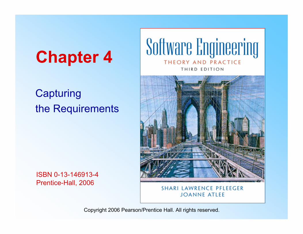
ISBN 0-13-146913-4Prentice-Hall, 2006
Chapter 4
Capturingthe Requirements
Copyright 2006 Pearson/Prentice Hall. All rights reserved.
Pfleeger and Atlee, Software Engineering: Theory and Practice Page 4.3© 2006 Pearson/Prentice Hall
Contents
4.1 The Requirements Process4.2 Requirements Elicitation4.3 Types of Requirements4.4 Characteristics of Requirements4.5 Modeling Notations4.6 Requirements and Specification Languages4.7 Prototyping Requirements4.8 Requirements Documentation4.9 Validation and Verification4.10 Measuring Requirements4.11 Choosing a Specification Technique4.12 Information System Example4.13 Real Time Example
Pfleeger and Atlee, Software Engineering: Theory and Practice Page 4.4© 2006 Pearson/Prentice Hall
Chapter 4 Objectives
• Eliciting requirements from the customers• Modeling requirements• Reviewing requirements to ensure their quality• Documenting requirements for use by the design
and test teams
Pfleeger and Atlee, Software Engineering: Theory and Practice Page 4.5© 2006 Pearson/Prentice Hall
4.1 The Requirements Process
• A requirement is an expression of desiredbehavior
• A requirement deals with– objects or entities– the state they can be in– functions that are performed to change states or object
characteristics• Requirements focus on the customer needs, not
on the solution or implementation– designate what behavior, without saying how that
behavior will be realized
Pfleeger and Atlee, Software Engineering: Theory and Practice Page 4.6© 2006 Pearson/Prentice Hall
4.1 The Requirements ProcessSidebar 4.1 Why Are Requirements Important?
• Top factors that caused project to fail– Incomplete requirements– Lack of user involvement– Unrealistic expectations– Lack of executive support– Changing requirements and specifications– Lack of planning– System no longer needed
• Some part of the requirements process is involved inalmost all of these causes
• Errors in Requirements can be expensive if not detectedearly
Pfleeger and Atlee, Software Engineering: Theory and Practice Page 4.7© 2006 Pearson/Prentice Hall
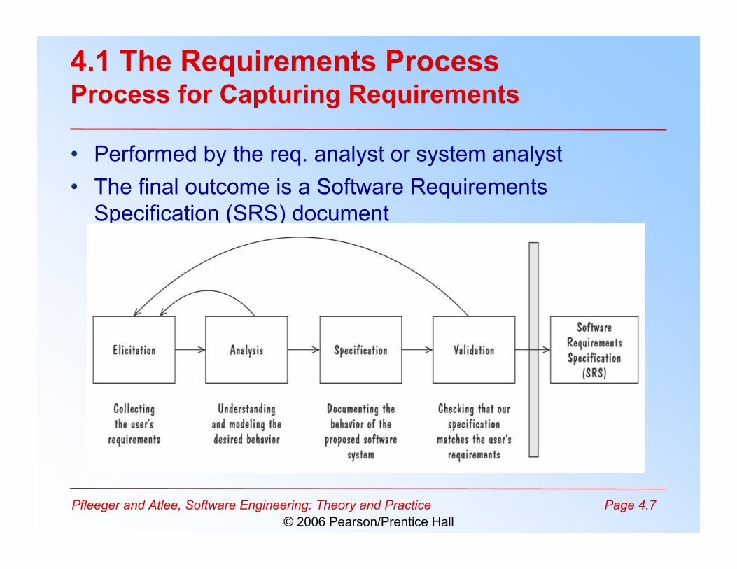
4.1 The Requirements ProcessProcess for Capturing Requirements
• Performed by the req. analyst or system analyst• The final outcome is a Software Requirements
Specification (SRS) document
Pfleeger and Atlee, Software Engineering: Theory and Practice Page 4.8© 2006 Pearson/Prentice Hall
4.1 The Requirements ProcessSidebar 4.2 Agile Requirements Modeling
• If requirements are tightly coupled and complex, we maybe better off with a “heavy” process that empasizes up-front modeling
• If the requirements are uncertain, agile methods are analternative approach
• Agile methods gather and implement the requirements inincrements
• Extreme Programming (XP) is an agile process– The requirements are defined as we build the system– No planning or designing for possible future requirements– Encodes the requirements as test cases that the eventual
implementation must pass
Pfleeger and Atlee, Software Engineering: Theory and Practice Page 4.9© 2006 Pearson/Prentice Hall
4.2 Requirements Elicitation
• Customers do not always understand what theirneeds and problems are
• It is important to discuss the requirements witheveryone who has a stake in the system
• We are working to come up with an agreement onwhat the requirements are– If we can not agree on what the requirements are, then
the project is doomed to fail
Pfleeger and Atlee, Software Engineering: Theory and Practice Page 4.10© 2006 Pearson/Prentice Hall
4.2 Requirements ElicitationStakeholders
• Clients: pay for the software to be developed• Customers: buy the software after it is developed• Users: use the system• Domain experts: familiar with the problem that the
software must automate• Market Researchers: conduct surveys to determine
future trends and potential customers• Lawyers or auditors: familiar with government, safety, or
legal requirements• Software engineers or other technology experts
Pfleeger and Atlee, Software Engineering: Theory and Practice Page 4.11© 2006 Pearson/Prentice Hall
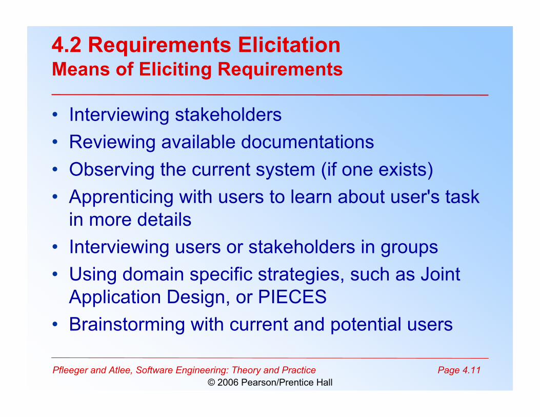
4.2 Requirements ElicitationMeans of Eliciting Requirements
• Interviewing stakeholders• Reviewing available documentations• Observing the current system (if one exists)• Apprenticing with users to learn about user's task
in more details• Interviewing users or stakeholders in groups• Using domain specific strategies, such as Joint
Application Design, or PIECES• Brainstorming with current and potential users
Pfleeger and Atlee, Software Engineering: Theory and Practice Page 4.12© 2006 Pearson/Prentice Hall
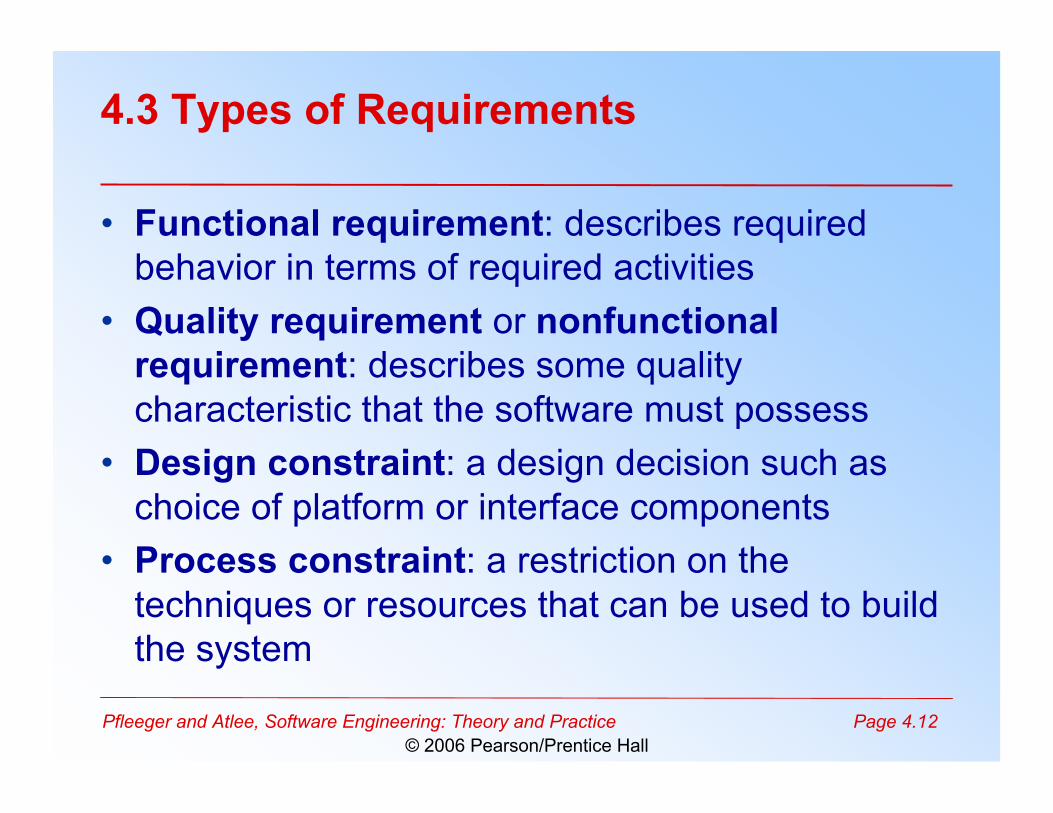
4.3 Types of Requirements
• Functional requirement: describes requiredbehavior in terms of required activities
• Quality requirement or nonfunctionalrequirement: describes some qualitycharacteristic that the software must possess
• Design constraint: a design decision such aschoice of platform or interface components
• Process constraint: a restriction on thetechniques or resources that can be used to buildthe system
Pfleeger and Atlee, Software Engineering: Theory and Practice Page 4.13© 2006 Pearson/Prentice Hall
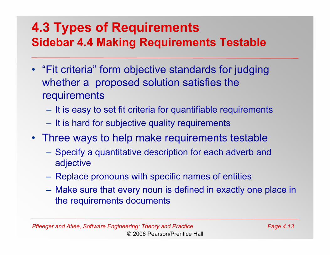
4.3 Types of RequirementsSidebar 4.4 Making Requirements Testable
• “Fit criteria” form objective standards for judgingwhether a proposed solution satisfies therequirements– It is easy to set fit criteria for quantifiable requirements– It is hard for subjective quality requirements
• Three ways to help make requirements testable– Specify a quantitative description for each adverb and
adjective– Replace pronouns with specific names of entities– Make sure that every noun is defined in exactly one place in
the requirements documents
Pfleeger and Atlee, Software Engineering: Theory and Practice Page 4.14© 2006 Pearson/Prentice Hall
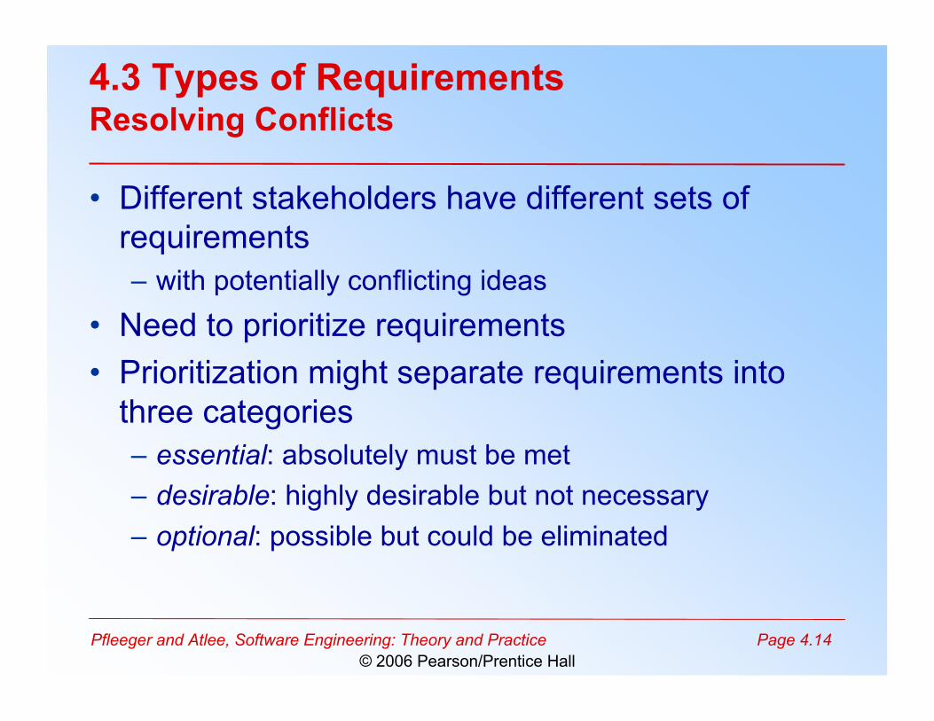
4.3 Types of RequirementsResolving Conflicts
• Different stakeholders have different sets ofrequirements– with potentially conflicting ideas
• Need to prioritize requirements• Prioritization might separate requirements into
three categories– essential: absolutely must be met– desirable: highly desirable but not necessary– optional: possible but could be eliminated
Pfleeger and Atlee, Software Engineering: Theory and Practice Page 4.15© 2006 Pearson/Prentice Hall
4.3 Types of RequirementsTwo Kinds of Requirements Documents
• Requirements definition: a complete listing ofeverything the customer wants to achieve– Describing the entities in the environment where the
system will be installed• Requirements specification: restates the
requirements as a specification of how theproposed system shall behave
Pfleeger and Atlee, Software Engineering: Theory and Practice Page 4.16© 2006 Pearson/Prentice Hall
4.3 Types of RequirementsTwo Kinds of Requirements Documents (continued)
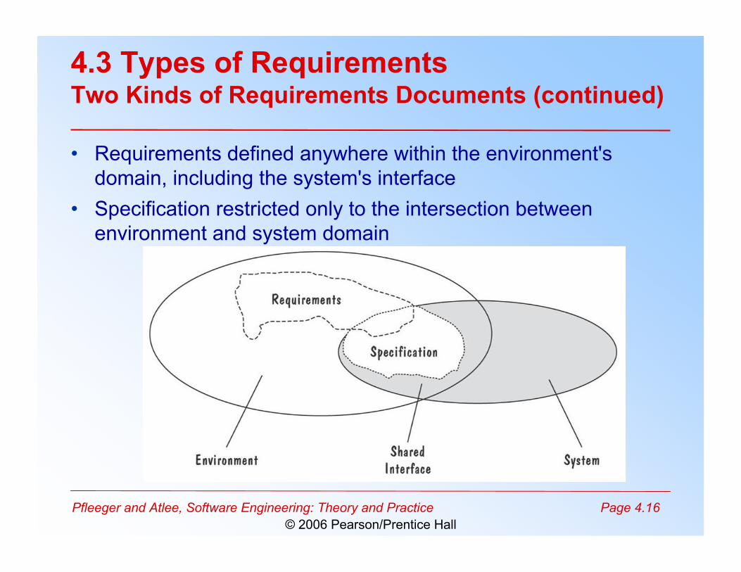
• Requirements defined anywhere within the environment'sdomain, including the system's interface
• Specification restricted only to the intersection betweenenvironment and system domain
Pfleeger and Atlee, Software Engineering: Theory and Practice Page 4.17© 2006 Pearson/Prentice Hall
4.4 Characteristics of Requirements
• Correct• Consistent• Unambigious• Complete• Feasible• Relevant• Testable• Traceable
Pfleeger and Atlee, Software Engineering: Theory and Practice Page 4.18© 2006 Pearson/Prentice Hall
4.5 Modeling Notations
• It is important to have standard notations formodeling, documenting, and communicatingdecisions
• Modeling helps us to understand requirementsthoroughly– Holes in the models reveal unknown or ambiguous
behavior– Multiple, conflicting outputs to the same input reveal
inconsistencies in the requirements
Pfleeger and Atlee, Software Engineering: Theory and Practice Page 4.19© 2006 Pearson/Prentice Hall
4.5 Modeling NotationsEntity-Relationship Diagrams
• A popular graphical notational paradigm forrepresenting conceptual models
• Has three core constructs– An entity: depicted as a rectangle, represents a
collection of real-world objects that have commonproperties and behaviors
– A relationship: depicted as an edge between twoentities, with diamond in the middle of the edgespecifying the type of relationship
– An attribute: an annotation on an entity that describesdata or properties associated with the entity
Pfleeger and Atlee, Software Engineering: Theory and Practice Page 4.20© 2006 Pearson/Prentice Hall
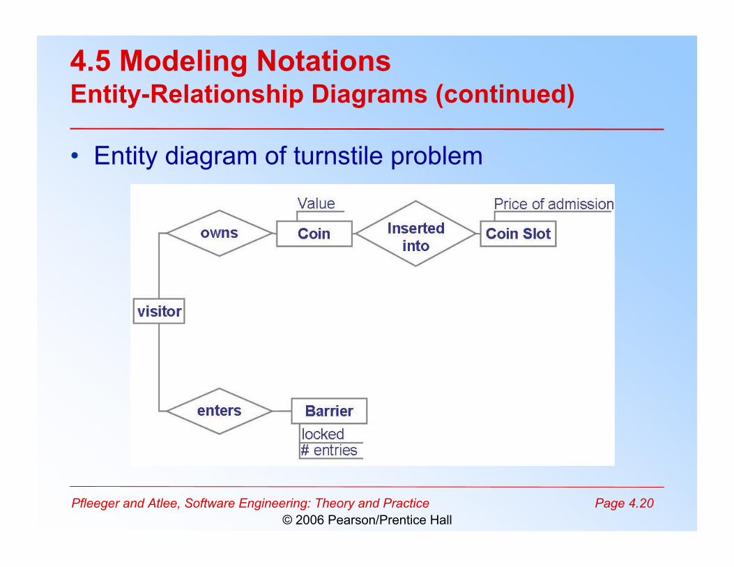
4.5 Modeling NotationsEntity-Relationship Diagrams (continued)
• Entity diagram of turnstile problem
Pfleeger and Atlee, Software Engineering: Theory and Practice Page 4.21© 2006 Pearson/Prentice Hall
4.5 Modeling NotationsEntity-Relationship Diagrams (continued)
• ER diagrams are popular because– they provide an overview of the problem to be
addressed– the view is relatively stable when changes are made to
the problem's requirements• ER diagram is likely to be used to model a
problem early in the requirements process
Pfleeger and Atlee, Software Engineering: Theory and Practice Page 4.22© 2006 Pearson/Prentice Hall
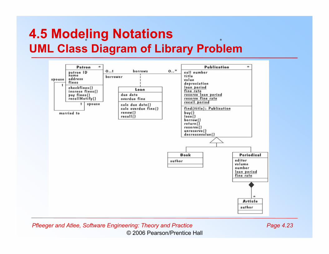
4.5 Modeling NotationsER Diagrams Example: UML Class Diagram
• UML (Unified Modeling Language) is acollection of notations used to document softwarespecifications and designs
• It represents a system in terms of– objects: akin to entities, organized in classes that have
an inheritance hierarchy– methods: actions on the object's variables
• The class diagram is the flagship model in anyUML specification– A sophisticated ER diagram relating the classes
(entities) in the specification
Pfleeger and Atlee, Software Engineering: Theory and Practice Page 4.23© 2006 Pearson/Prentice Hall
4.5 Modeling NotationsUML Class Diagram of Library Problem
∗ ∗
Pfleeger and Atlee, Software Engineering: Theory and Practice Page 4.24© 2006 Pearson/Prentice Hall
4.5 Modeling NotationsEvent Traces
• A graphical description of a sequence of events thatare exchanged between real-world entities– Vertical line: the timeline of distinct entity, whose name
appears at the top of the line– Horizontal line: an event or interaction between the two
entities bounding the line– Time progresses from top to bottom
• Each graph depicts a single trace, representing oneof several possible behaviors
• Traces have semantics that are relatively precise,simple and easy to understand
Pfleeger and Atlee, Software Engineering: Theory and Practice Page 4.25© 2006 Pearson/Prentice Hall
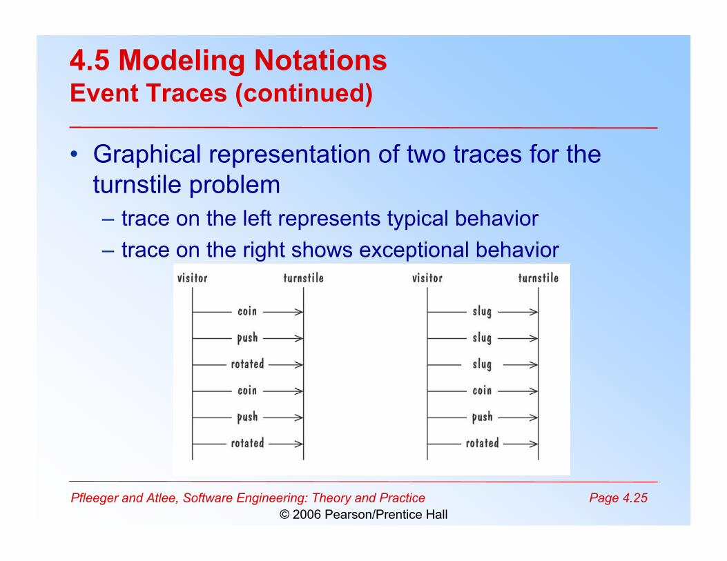
4.5 Modeling NotationsEvent Traces (continued)
• Graphical representation of two traces for theturnstile problem– trace on the left represents typical behavior– trace on the right shows exceptional behavior
Pfleeger and Atlee, Software Engineering: Theory and Practice Page 4.26© 2006 Pearson/Prentice Hall
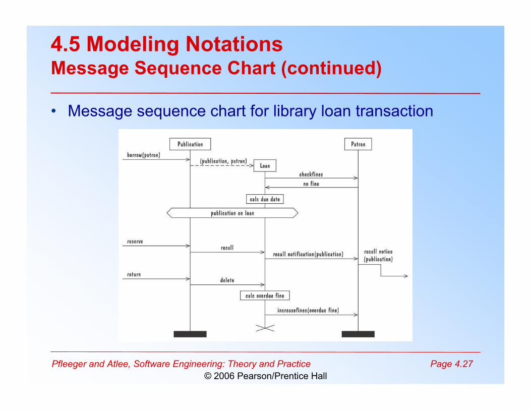
4.5 Modeling NotationsEvent Traces Example: Message Sequence Chart
• An enhanced event-trace notation, with facilitiesfor creating and destroying entities, specifiyingactions and timers, and composing traces– Vertical line represents a participating entity– A message is depicted as an arrow from the sending
entity to the receiving entity– Actions are specified as labeled rectangles positioned
on an entity's execution line– Conditions are important states in an entity's evolution,
represented as labeled hexagon
Pfleeger and Atlee, Software Engineering: Theory and Practice Page 4.27© 2006 Pearson/Prentice Hall
4.5 Modeling NotationsMessage Sequence Chart (continued)
• Message sequence chart for library loan transaction
Pfleeger and Atlee, Software Engineering: Theory and Practice Page 4.28© 2006 Pearson/Prentice Hall
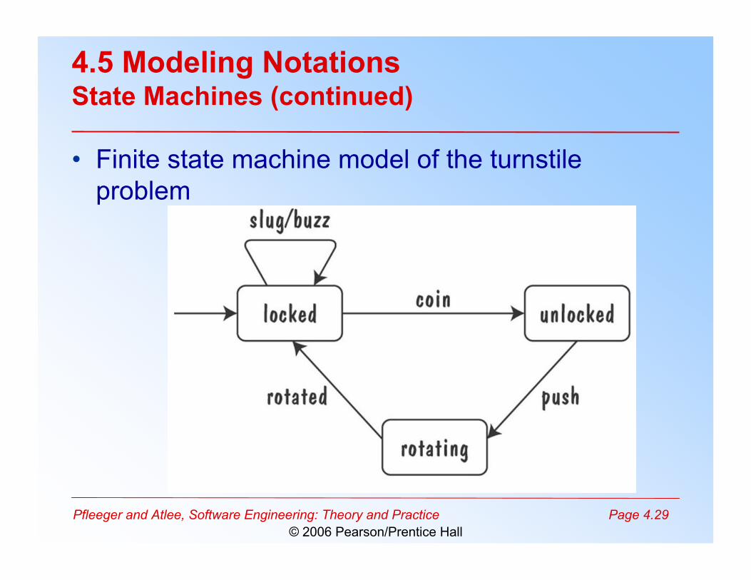
4.5 Modeling NotationsState Machines
• A graphical description of all dialog between thesystem and its environment– Node (state) represents a stable set of conditions that
exists between event occurences– Edge (transition) represents a change in behavior or
condition due to the occurrence of an event• Useful both for specifying dynamic behavior and
for describing how behavior should change inresponse to the history of events that havealready occurred
Pfleeger and Atlee, Software Engineering: Theory and Practice Page 4.29© 2006 Pearson/Prentice Hall
4.5 Modeling NotationsState Machines (continued)
• Finite state machine model of the turnstileproblem
Pfleeger and Atlee, Software Engineering: Theory and Practice Page 4.30© 2006 Pearson/Prentice Hall
4.5 Modeling NotationsState Machines Example: UML Statechart Diagrams
• A UML statechart diagram depicts the dynamicbehavior of the objects in a UML class– UML class diagram has no information about how the
entities behave, how the behaviors change• A UML model is a collection of concurrently
executing statecharts• UML statechart diagram has a rich syntax,
including state hierarchy, concurrency, andintermachine communication
Pfleeger and Atlee, Software Engineering: Theory and Practice Page 4.31© 2006 Pearson/Prentice Hall
4.5 Modeling NotationsUML Statechart Diagrams (continued)
• State hierarchy is used to unclutter diagrams bycollecting into superstate those states withcommon transitions
• A superstate can actually comprise multipleconcurrent submachines, separated by dashedlines– The submachines are said to operate concurrently
Pfleeger and Atlee, Software Engineering: Theory and Practice Page 4.32© 2006 Pearson/Prentice Hall
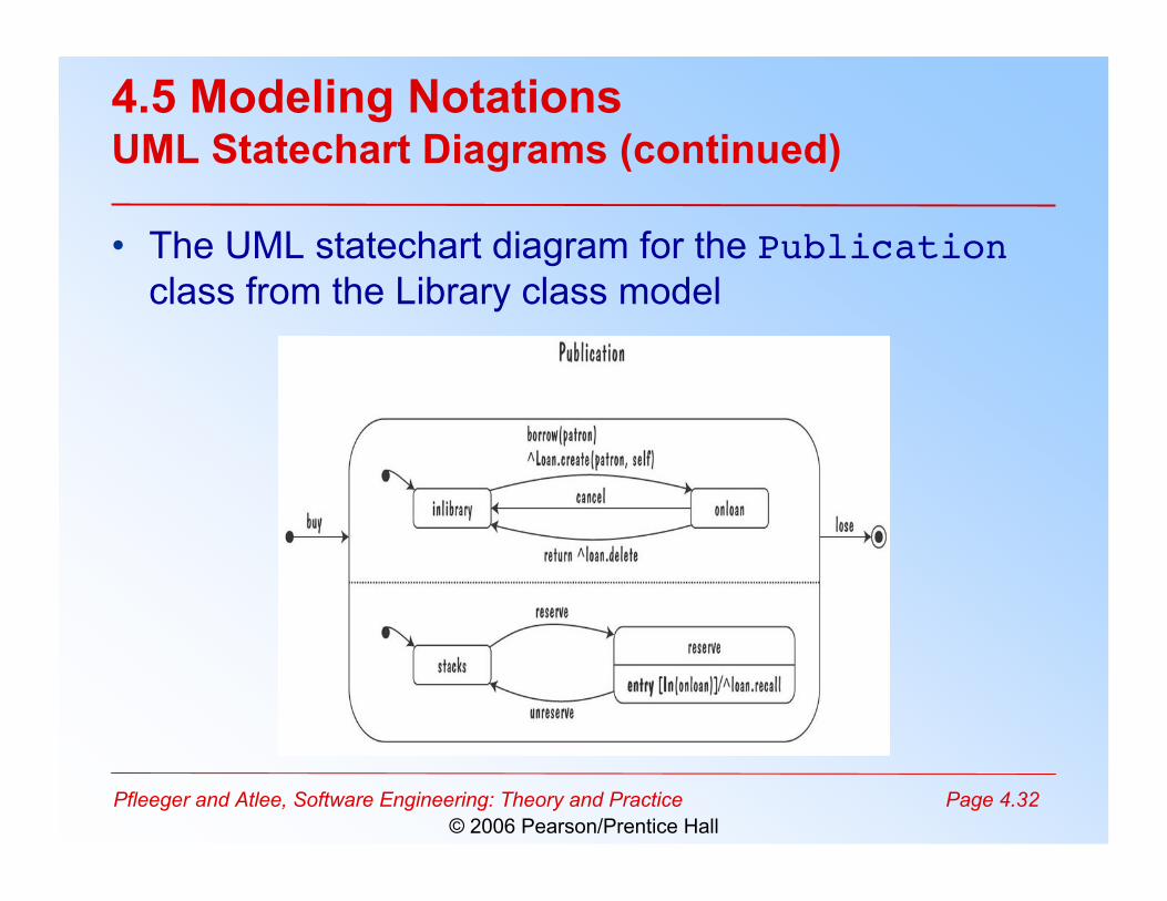
4.5 Modeling NotationsUML Statechart Diagrams (continued)
• The UML statechart diagram for the Publicationclass from the Library class model

Pfleeger and Atlee, Software Engineering: Theory and Practice Page 4.33© 2006 Pearson/Prentice Hall
4.5 Modeling NotationsUML Statechart Diagrams (continued)
• An equivalent statechart for Publication class that does not makeuse of state hierarchy or concurrency
– comparatively messy and and repetitive
Pfleeger and Atlee, Software Engineering: Theory and Practice Page 4.34© 2006 Pearson/Prentice Hall
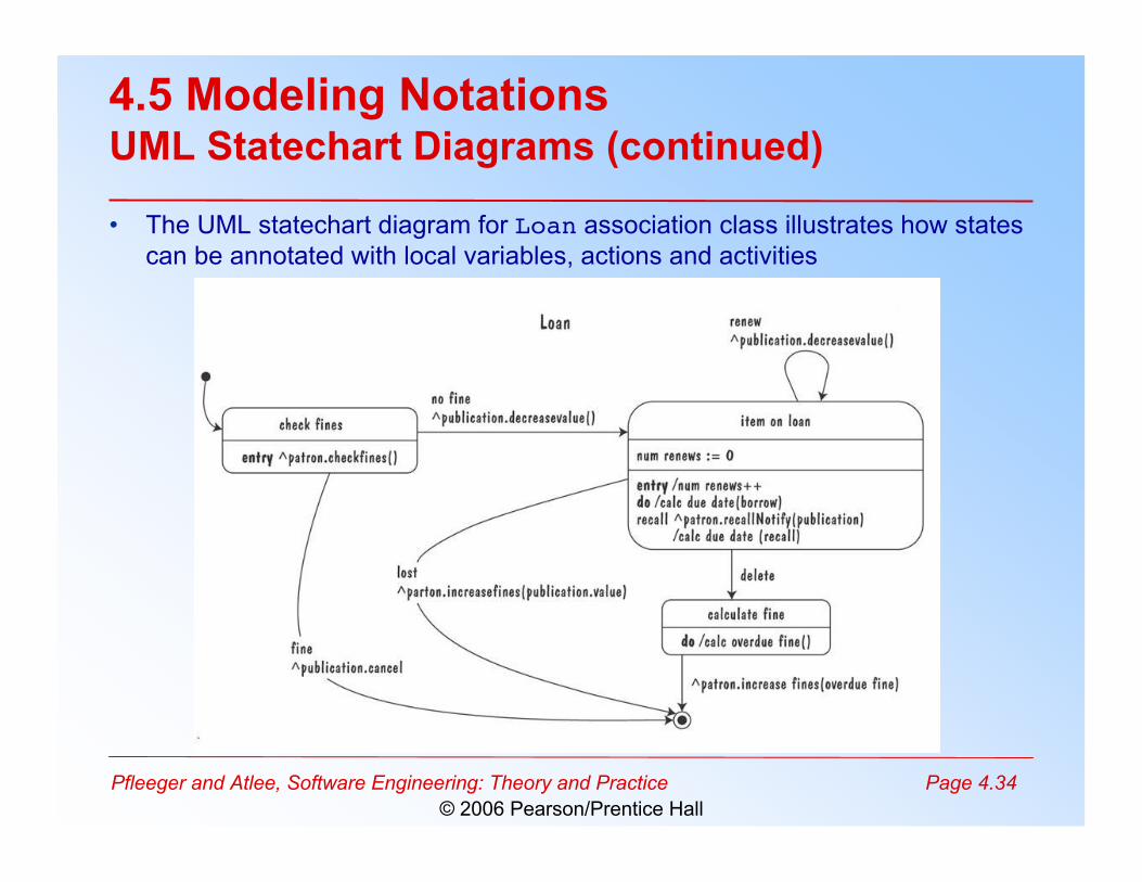
4.5 Modeling NotationsUML Statechart Diagrams (continued)
• The UML statechart diagram for Loan association class illustrates how statescan be annotated with local variables, actions and activities
Pfleeger and Atlee, Software Engineering: Theory and Practice Page 4.35© 2006 Pearson/Prentice Hall
4.5 Modeling NotationsState Machines: Ways of Thinking about State
• Equivalence classes of possible future behavior• Periods of time between consecutive event• Named control points in an object's evolution• Partition of an object's behavior
Pfleeger and Atlee, Software Engineering: Theory and Practice Page 4.36© 2006 Pearson/Prentice Hall
4.5 Modeling NotationsState Machines Example: Petri Nets
• A form or state-transition notation that is used tomodel concurrent activities and their interaction– Circles (places) represent activities or conditions– Bars represents transitions– Arcs connect a transition with its input places and its
output places– The places are populated with tokens, which act as
enabling conditions for the transitions– Each arc can be assigned a weight that specifies how
many tokens are removed from arc's input place, whenthe transition fires
Pfleeger and Atlee, Software Engineering: Theory and Practice Page 4.37© 2006 Pearson/Prentice Hall
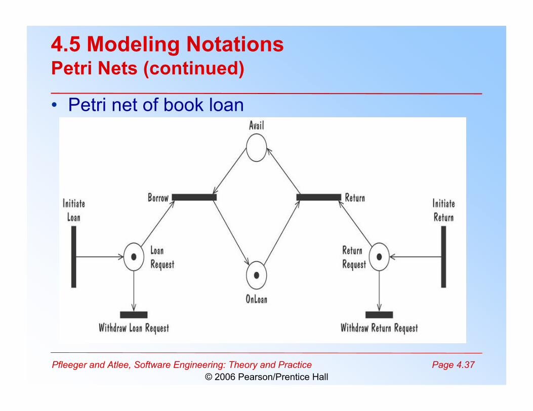
4.5 Modeling NotationsPetri Nets (continued)
• Petri net of book loan
Pfleeger and Atlee, Software Engineering: Theory and Practice Page 4.38© 2006 Pearson/Prentice Hall
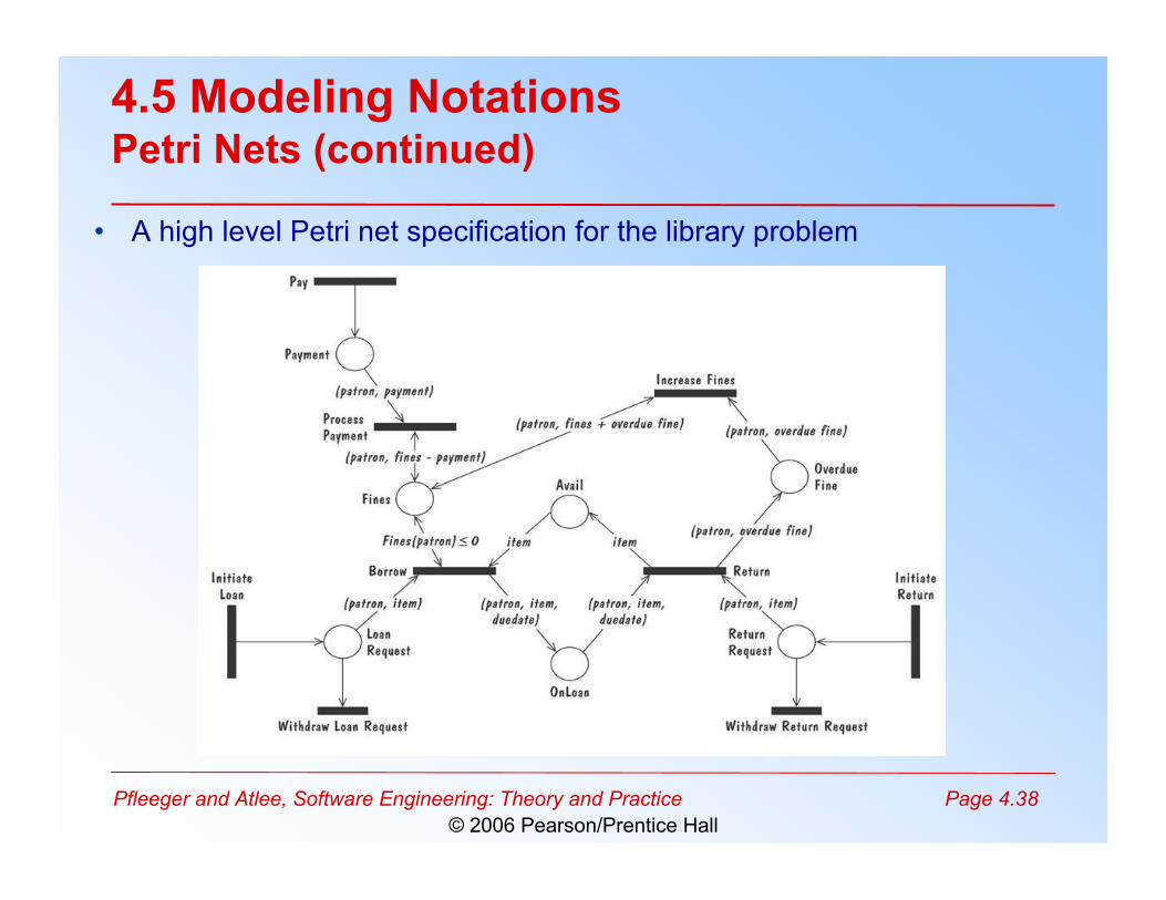
4.5 Modeling NotationsPetri Nets (continued)
• A high level Petri net specification for the library problem
Pfleeger and Atlee, Software Engineering: Theory and Practice Page 4.39© 2006 Pearson/Prentice Hall
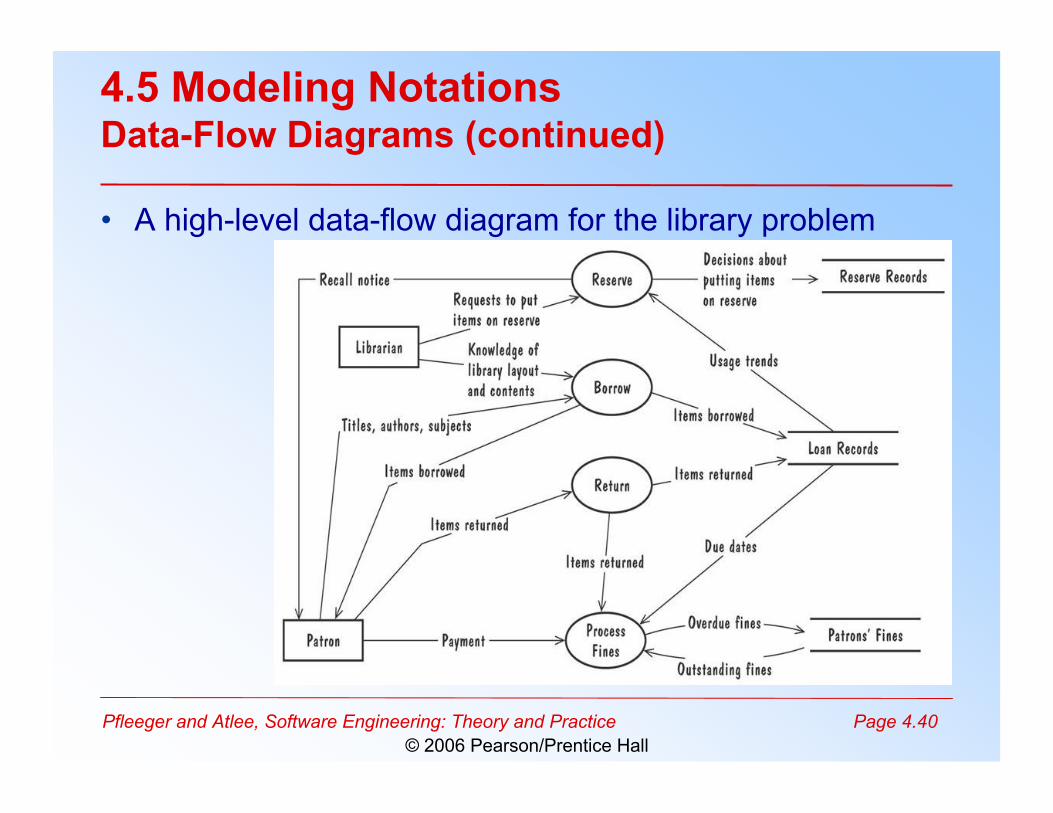
4.5 Modeling NotationsData-Flow Diagrams
• ER diagram, event trace, state machines depictonly lower-level behaviors
• A data-flow diagram (DFD) models functionalityand the flow of data from one function to another– A bubble represents a process– An arrow represents data flow– A data store: a formal repository or database of
information– Rectangles represent actors: entities that provide input
data or receive the output result
Pfleeger and Atlee, Software Engineering: Theory and Practice Page 4.40© 2006 Pearson/Prentice Hall
4.5 Modeling NotationsData-Flow Diagrams (continued)
• A high-level data-flow diagram for the library problem
Pfleeger and Atlee, Software Engineering: Theory and Practice Page 4.41© 2006 Pearson/Prentice Hall
4.5 Modeling NotationsData-Flow Diagrams (continued)
• Advantage:– Provides an intuitive model of a proposed system's
high-level functionality and of the data dependenciesamong various processes
• Disadvantage:– Can be aggravatingly ambiguous to a software
developer who is less familiar with the problem beingmodeled
Pfleeger and Atlee, Software Engineering: Theory and Practice Page 4.42© 2006 Pearson/Prentice Hall
4.5 Modeling NotationsData-Flow Diagrams Example: Use Cases
• Components– A large box: system boundary– Stick figures outside the box: actors, both human and
systems– Each oval inside the box: a use case that represents
some major required functionality and its variant– A line between an actor and use case: the actor
participates in the use case• Use cases do not model all the tasks, instead they
are used to specify user views of essential systembehavior
Pfleeger and Atlee, Software Engineering: Theory and Practice Page 4.43© 2006 Pearson/Prentice Hall
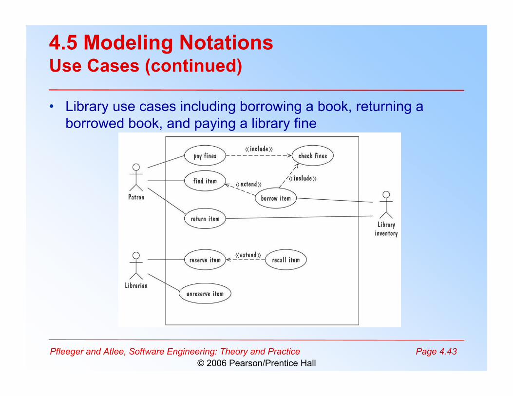
4.5 Modeling NotationsUse Cases (continued)
• Library use cases including borrowing a book, returning aborrowed book, and paying a library fine
Pfleeger and Atlee, Software Engineering: Theory and Practice Page 4.44© 2006 Pearson/Prentice Hall
4.5 Modeling NotationsFunctions and Relations
• Formal methods or approach: mathematicallybased specification and design techniques
• Formal methods model requirements or softwarebehavior as a collection of mathematicalfunctions or relations– Functions specify the state of the system's execution,
and output– A relation is used whenever an input value maps more
than one ouput value• Functional method is consistent and complete
Pfleeger and Atlee, Software Engineering: Theory and Practice Page 4.45© 2006 Pearson/Prentice Hall
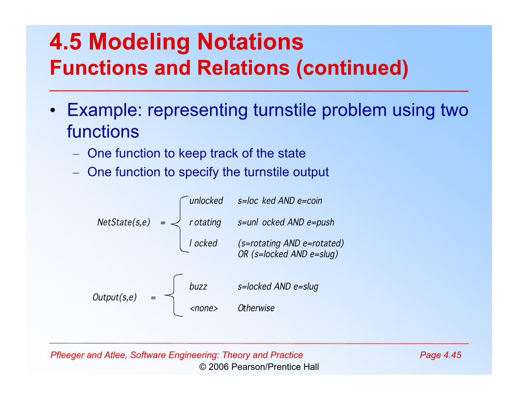
4.5 Modeling NotationsFunctions and Relations (continued)
• Example: representing turnstile problem using twofunctions– One function to keep track of the state– One function to specify the turnstile output
unlocked s=loc ked AND e=coin NetState(s,e) = r otating s=unl ocked AND e=push l ocked (s=rotating AND e=rotated) OR (s=locked AND e=slug) buzz s=locked AND e=slug Output(s,e) = <none> Otherwise
Pfleeger and Atlee, Software Engineering: Theory and Practice Page 4.46© 2006 Pearson/Prentice Hall
4.5 Modeling NotationsFunctions and Relations Example: Decision Tables
• It is a tabular representation of a functionalspecification that maps events and conditions toappropriate responses or action
• The specification is informal because the inputs(events and conditions) and outputs (actions) maybe expressed in natural language
• If there is n input conditions, there are 2n possiblecombinations of input conditions
• Combinations map to the same set of results andcan be combined into a single column
Pfleeger and Atlee, Software Engineering: Theory and Practice Page 4.47© 2006 Pearson/Prentice Hall
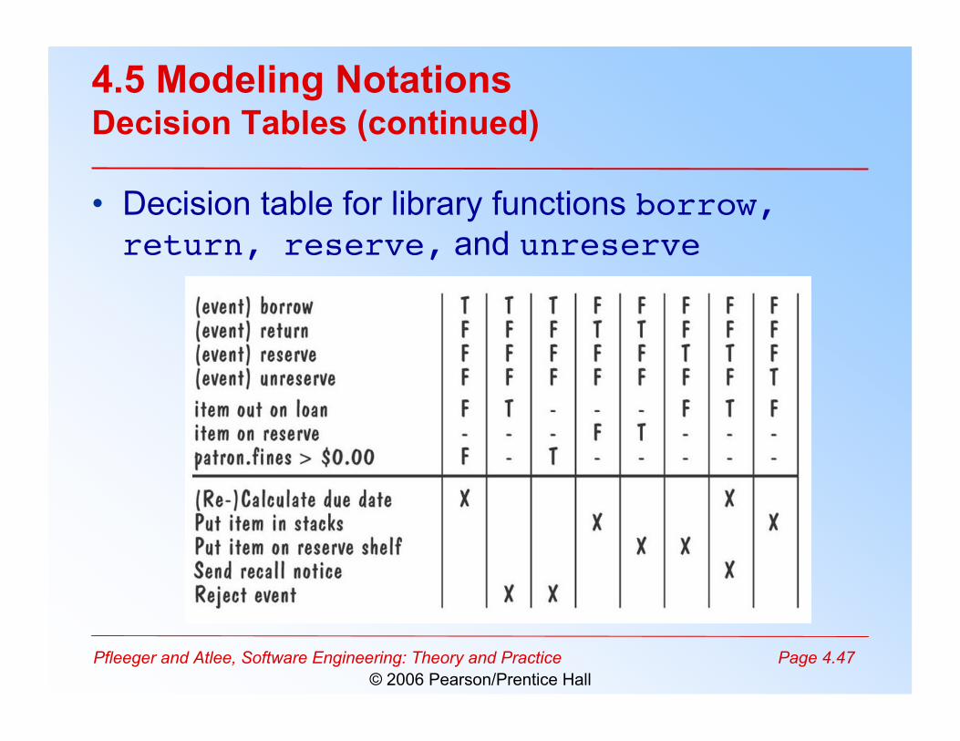
4.5 Modeling NotationsDecision Tables (continued)
• Decision table for library functions borrow,return, reserve, and unreserve
Pfleeger and Atlee, Software Engineering: Theory and Practice Page 4.48© 2006 Pearson/Prentice Hall
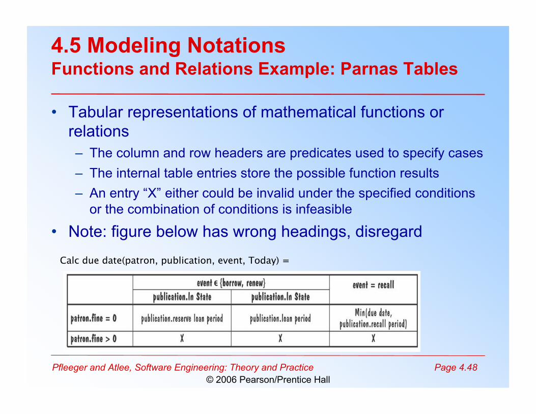
4.5 Modeling NotationsFunctions and Relations Example: Parnas Tables
• Tabular representations of mathematical functions orrelations– The column and row headers are predicates used to specify cases– The internal table entries store the possible function results– An entry “X” either could be invalid under the specified conditions
or the combination of conditions is infeasible
• Note: figure below has wrong headings, disregard
Calc due date(patron, publication, event, Today) =
Pfleeger and Atlee, Software Engineering: Theory and Practice Page 4.49© 2006 Pearson/Prentice Hall
4.5 Modeling NotationsLogic
• An operational notation is a notation used todescribe a problem or a proposed softwaresolution in terms of situational behavior– Model of case-based behavior– Examples: state machine, event traces, data-flow
diagram, functional method• A descriptive notation is a notation that
describes a problem or a proposed solution interms of its properties or its variants– Example: logic
Pfleeger and Atlee, Software Engineering: Theory and Practice Page 4.50© 2006 Pearson/Prentice Hall
4.5 Modeling NotationsLogic (continued)
• A logic consists of a language for expressingproperties and a set of inference rules for derivingnew, consequent properties from the statedproperties
• In logic, a property specification represents onlythose values of the property's variables for whichthe property's expression evaluates to true– The logic used for specifying software requirements is
almost always first-order logic, with its typed variables,constants, functions, and predicates
– Another common logic usd for software requirements istemporal logic
Pfleeger and Atlee, Software Engineering: Theory and Practice Page 4.51© 2006 Pearson/Prentice Hall
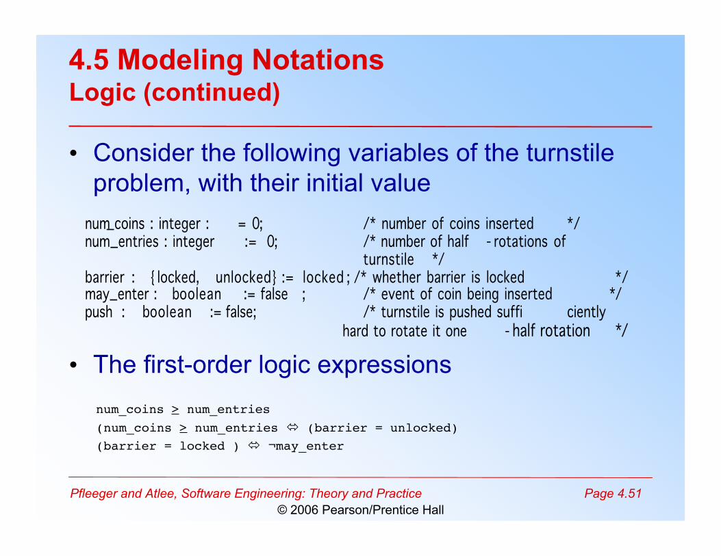
4.5 Modeling NotationsLogic (continued)
• Consider the following variables of the turnstileproblem, with their initial value
• The first-order logic expressions
num_coins : integer : = 0; /* number of coins inserted */ num_entries : integer := 0; /* number of half - rotations of
turnstile */ barrier : { locked, unlocked} := locked ; /* whether barrier is locked */ may_enter : boolean := false ; /* event of coin being inserted */ push : boolean := false; /* turnstile is pushed suffi ciently hard to rotate it one - half rotation */
num_coins > num_entries(num_coins > num_entries (barrier = unlocked)(barrier = locked ) ¬may_enter
Pfleeger and Atlee, Software Engineering: Theory and Practice Page 4.52© 2006 Pearson/Prentice Hall
4.5 Modeling NotationsLogic (continued)
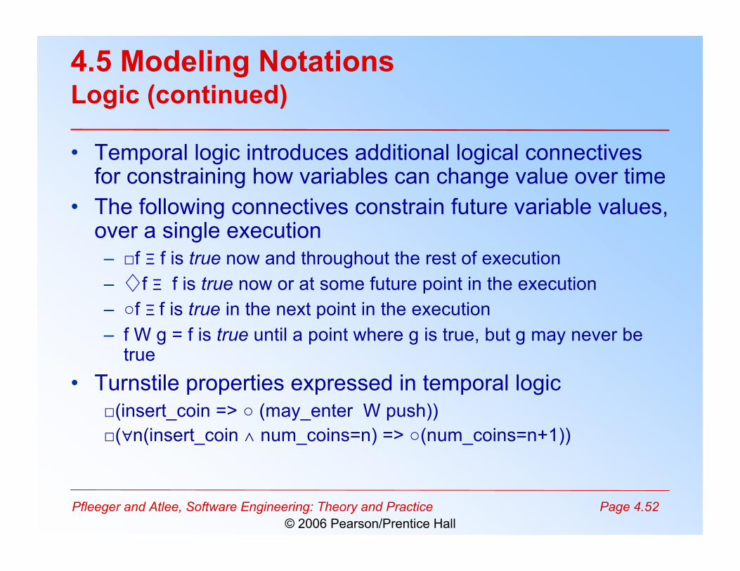
• Temporal logic introduces additional logical connectivesfor constraining how variables can change value over time
• The following connectives constrain future variable values,over a single execution– □f Ξ f is true now and throughout the rest of execution– ♢f Ξ f is true now or at some future point in the execution– ○f Ξ f is true in the next point in the execution– f W g = f is true until a point where g is true, but g may never be
true• Turnstile properties expressed in temporal logic
□(insert_coin => ○ (may_enter W push))□(∀n(insert_coin ∧ num_coins=n) => ○(num_coins=n+1))
Pfleeger and Atlee, Software Engineering: Theory and Practice Page 4.53© 2006 Pearson/Prentice Hall
4.5 Modeling NotationsLogic Example: Object Constrain Language (OCL)
• A constraint language that is both mathematicallyprecise and easy for non-mathematicians to read,write, and understand
• Designed for expressing constraints on objectmodels, and expressing queries on object type
Pfleeger and Atlee, Software Engineering: Theory and Practice Page 4.54© 2006 Pearson/Prentice Hall
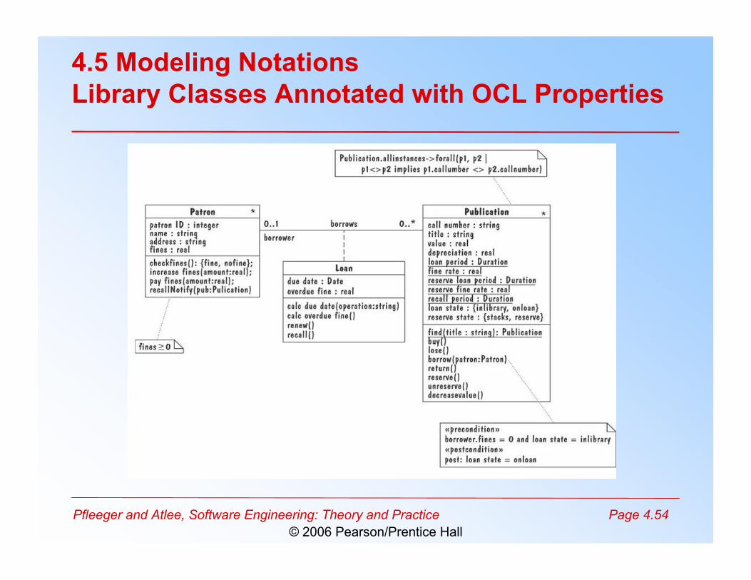
4.5 Modeling NotationsLibrary Classes Annotated with OCL Properties
Pfleeger and Atlee, Software Engineering: Theory and Practice Page 4.55© 2006 Pearson/Prentice Hall
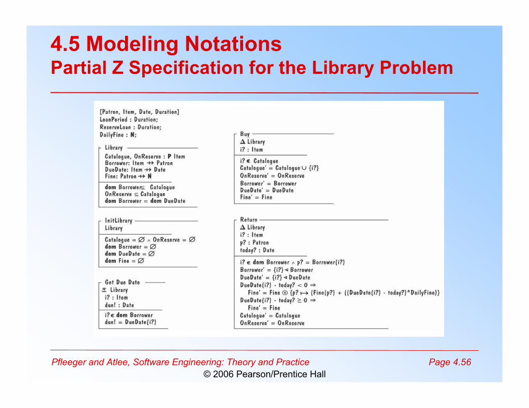
4.5 Modeling NotationsLogic Example: Z
• A formal requirements-specification language that– structures set-theoretic definitions of variables into a
complete abstract-data-type model of a problem– uses logic to express the pre- and post-conditions for
each operation• Methods of abstractions are used to decompose a
specification into manageable sized modules,called schemas
Pfleeger and Atlee, Software Engineering: Theory and Practice Page 4.56© 2006 Pearson/Prentice Hall
4.5 Modeling NotationsPartial Z Specification for the Library Problem
Pfleeger and Atlee, Software Engineering: Theory and Practice Page 4.57© 2006 Pearson/Prentice Hall
4.5 Modeling NotationsAlgebraic Specifications
• To specify the behavior of operations byspecifying interactions between pairs ofoperations rather than modeling individualoperations
• It is hard to define a set of axioms that iscomplete and consistent and that reflects thedesired behavior
Pfleeger and Atlee, Software Engineering: Theory and Practice Page 4.58© 2006 Pearson/Prentice Hall
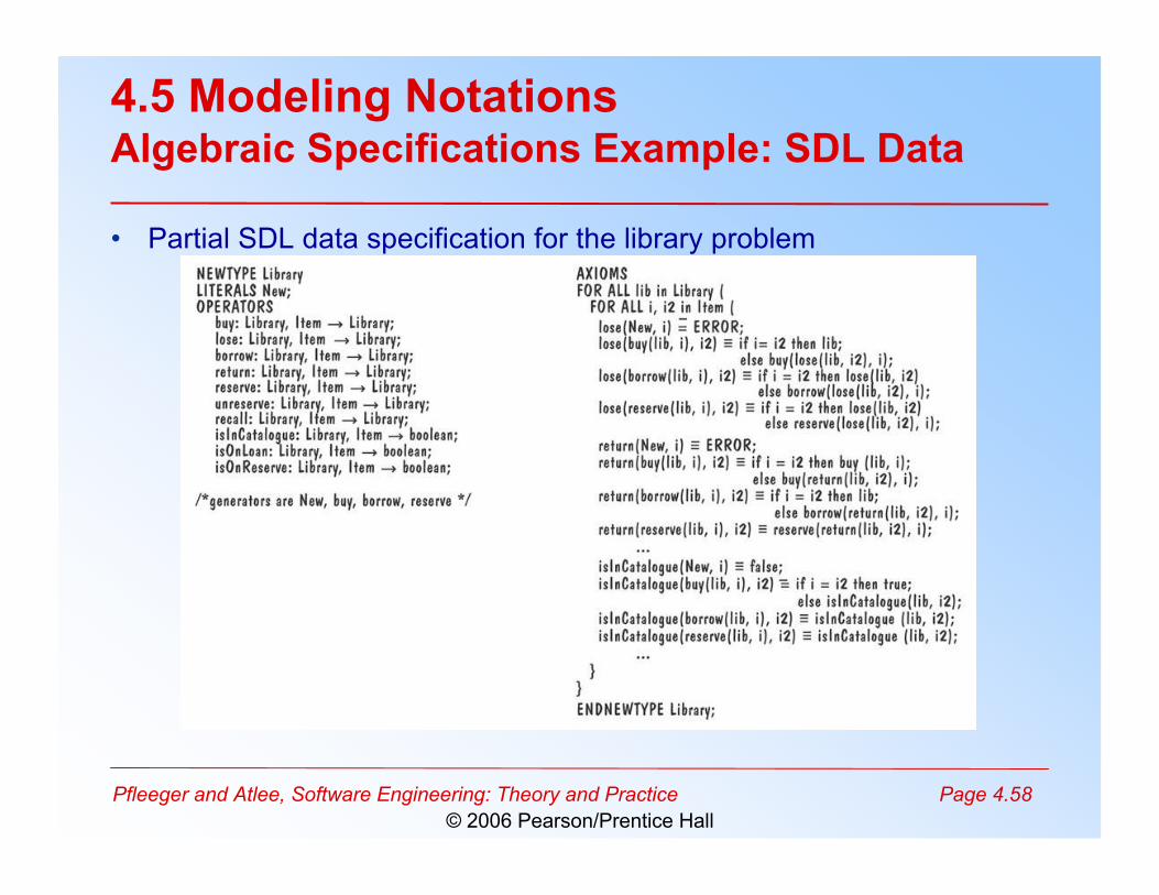
4.5 Modeling NotationsAlgebraic Specifications Example: SDL Data
• Partial SDL data specification for the library problem
Pfleeger and Atlee, Software Engineering: Theory and Practice Page 4.59© 2006 Pearson/Prentice Hall
4.6 Requirements and Specification Languages
• Note: Skipping Section 4.6
Pfleeger and Atlee, Software Engineering: Theory and Practice Page 4.60© 2006 Pearson/Prentice Hall
4.7 Prototyping RequirementsBuilding a Prototype
• To elicit the details of proposed system• To solicit feedback from potential users about
– which aspects they would like to see improve– which features are not so useful– what functionality is missing
• Determine whether the customer's problem has afeasible solution
• Assist in exploring options for optimizing qualityrequirements
Pfleeger and Atlee, Software Engineering: Theory and Practice Page 4.61© 2006 Pearson/Prentice Hall
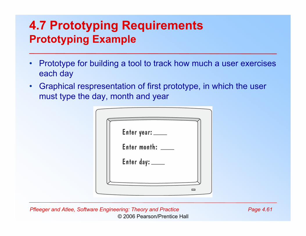
4.7 Prototyping RequirementsPrototyping Example
• Prototype for building a tool to track how much a user exerciseseach day
• Graphical respresentation of first prototype, in which the usermust type the day, month and year
Pfleeger and Atlee, Software Engineering: Theory and Practice Page 4.62© 2006 Pearson/Prentice Hall
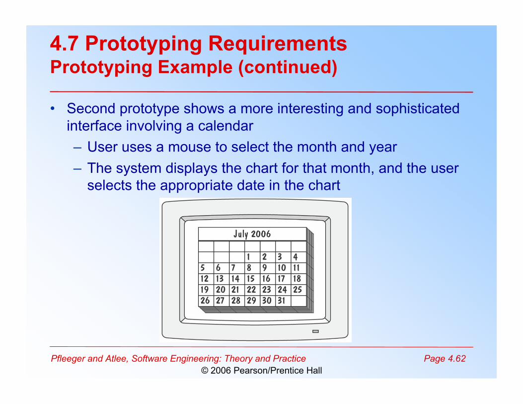
4.7 Prototyping RequirementsPrototyping Example (continued)
• Second prototype shows a more interesting and sophisticatedinterface involving a calendar– User uses a mouse to select the month and year– The system displays the chart for that month, and the user
selects the appropriate date in the chart
Pfleeger and Atlee, Software Engineering: Theory and Practice Page 4.63© 2006 Pearson/Prentice Hall
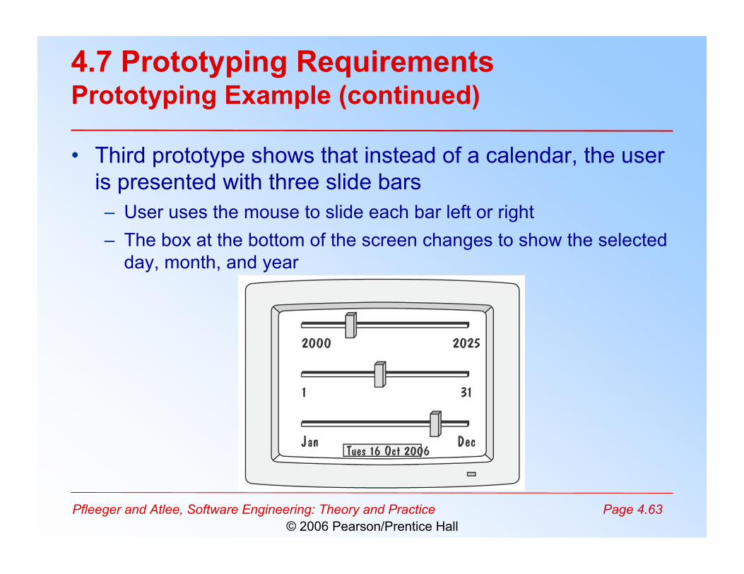
4.7 Prototyping RequirementsPrototyping Example (continued)
• Third prototype shows that instead of a calendar, the useris presented with three slide bars– User uses the mouse to slide each bar left or right– The box at the bottom of the screen changes to show the selected
day, month, and year
Pfleeger and Atlee, Software Engineering: Theory and Practice Page 4.64© 2006 Pearson/Prentice Hall
4.7 Prototyping RequirementsApproaches to Prototyping
• Throwaway approach– Developed to learn more about a problem or a proposed
solution, and that is never intended to be part of thedelivered software
– Allows us to write “quick-and-dirty” software• Evolutionary approach
– Developed not only to help us answer questions but also tobe incorporated into the final product
– Prototype has to eventually exhibit the quality requirementsof the final product, and these qualities cannot be retrofitted
• Both techniques are sometimes called rapidprototyping
Pfleeger and Atlee, Software Engineering: Theory and Practice Page 4.65© 2006 Pearson/Prentice Hall
4.7 Prototyping RequirementsPrototyping vs. Modeling
• Prototyping– Good for answering questions about the user interfaces
• Modeling– Quickly answer questions about constraints on the
order in which events should occur, or about thesynchronization of activities
Pfleeger and Atlee, Software Engineering: Theory and Practice Page 4.66© 2006 Pearson/Prentice Hall
4.8 Requirements DocumentationRequirements Definition: Steps Documenting Process
• Outline the general purpose and scope of the system, includingrelevant benefits, objectives, and goals
• Describe the background and the rationale behind proposal fornew system
• Describe the essential characteristics of an acceptable solution• Describe the environment in which the system will operate• Outline a description of the proposal, if the customer has a
proposal for solving the problem• List any assumptions we make about how the environment
behaves
Pfleeger and Atlee, Software Engineering: Theory and Practice Page 4.67© 2006 Pearson/Prentice Hall
4.8 Requirements DocumentationRequirements Specification: Steps Documenting Process
• Describe all inputs and outputs in detail, including– the sources of inputs– the destinations of outputs,– the value ranges– data format of inputs and outputs data– data protocols– window formats and organizations– timing constraint
• Restate the required functionality in terms of theinterfaces' inputs and outputs
• Devise fit criteria for each of the customer's qualityrequirements
Pfleeger and Atlee, Software Engineering: Theory and Practice Page 4.68© 2006 Pearson/Prentice Hall
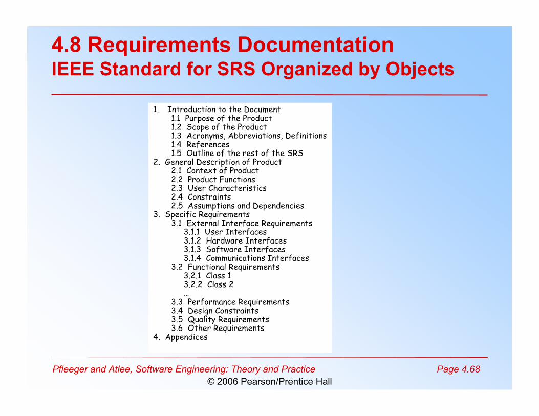
4.8 Requirements DocumentationIEEE Standard for SRS Organized by Objects
1. Introduction to the Document1.1 Purpose of the Product1.2 Scope of the Product1.3 Acronyms, Abbreviations, Definitions1.4 References1.5 Outline of the rest of the SRS
2. General Description of Product2.1 Context of Product2.2 Product Functions2.3 User Characteristics2.4 Constraints2.5 Assumptions and Dependencies
3. Specific Requirements3.1 External Interface Requirements
3.1.1 User Interfaces3.1.2 Hardware Interfaces3.1.3 Software Interfaces3.1.4 Communications Interfaces
3.2 Functional Requirements3.2.1 Class 13.2.2 Class 2…
3.3 Performance Requirements3.4 Design Constraints3.5 Quality Requirements3.6 Other Requirements
4. Appendices
Pfleeger and Atlee, Software Engineering: Theory and Practice Page 4.69© 2006 Pearson/Prentice Hall
4.8 Requirements DocumentationProcess Management and Requirements Traceability
• Process management is a set of procedures thattrack– the requirements that define what the system should do– the design modules that are generated from the requirement– the program code that implements the design– the tests that verify the functionality of the system– the documents that describe the system
• It provides the threads that tie the system partstogether
Pfleeger and Atlee, Software Engineering: Theory and Practice Page 4.70© 2006 Pearson/Prentice Hall
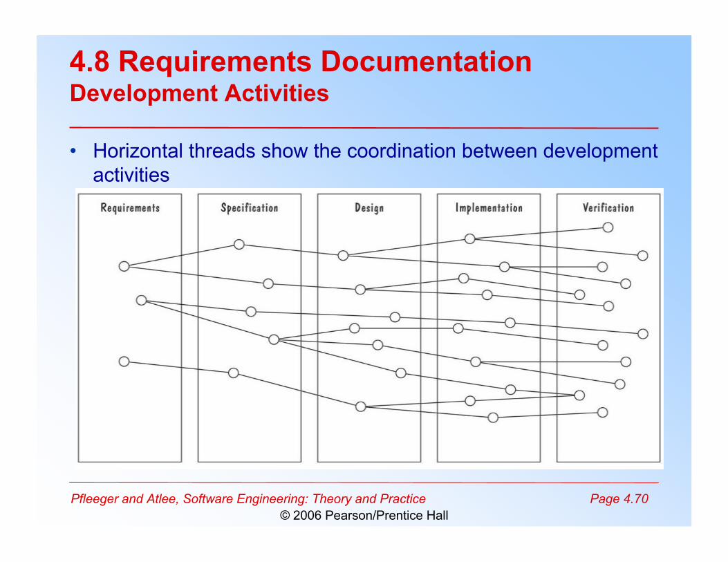
4.8 Requirements DocumentationDevelopment Activities
• Horizontal threads show the coordination between developmentactivities
Pfleeger and Atlee, Software Engineering: Theory and Practice Page 4.71© 2006 Pearson/Prentice Hall
4.9 Validation and Verification
• In requirements validation, we check that ourrequirements definition accurately reflects thecustomer's needs
• In verification, we check that one document orartifact conforms to another
• Verification ensures that we build the systemright, whereas validation ensures that we build theright system
Pfleeger and Atlee, Software Engineering: Theory and Practice Page 4.72© 2006 Pearson/Prentice Hall
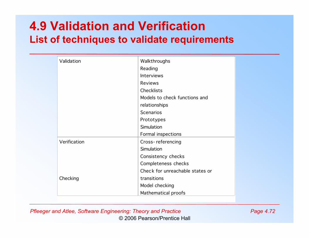
4.9 Validation and VerificationList of techniques to validate requirements
Validation Walkthroughs
Reading
Interviews
Reviews
Checklists
Models to check functions and
relationships
Scenarios
Prototypes
Simulation
Formal inspections
Verification
Checking
Cross- referencing
Simulation
Consistency checks
Completeness checks
Check for unreachable states or
transitions
Model checking
Mathematical proofs
Pfleeger and Atlee, Software Engineering: Theory and Practice Page 4.73© 2006 Pearson/Prentice Hall
4.9 Validation and VerificationRequirements Review
• Review the stated goals and objectives of the system• Compare the requirements with the goals and objectives• Review the environment in which the system is to operate• Review the information flow and proposed functions• Assess and document the risk, discuss and compare
alternatives• Testing the system: how the requirements will be
revalidated as the requirements grow and change
Pfleeger and Atlee, Software Engineering: Theory and Practice Page 4.74© 2006 Pearson/Prentice Hall
4.9 Validation and VerificationSidebar 4.8 Number of Requirements Faults
• Jone and Thayes's studies show that– 35% of the faults attributed to design activities for projects of 30,000-
35,000 delivered source instructions– 10% of the faults attributed to requirements activities and 55% of the
faults attributed to design activities for projects of 40,000-80,000 deliveredsource instructions
– 8% to 10% of the faults attributed to requirements activities and 40% to55% of the faults attributed to design activities for projects of 65,000-85,000 delivered source instructions
• Basili and Perricone report– 48% of the faults observed in a medium-scale software project were
attributed to “incorrect or misinterpreted functional specification orrequirements”
• Beizer attributes 8.12% of the faults in his samples toproblems in functional requirements
Pfleeger and Atlee, Software Engineering: Theory and Practice Page 4.75© 2006 Pearson/Prentice Hall
4.9 Validation and VerificationVerification
• Check that the requirements-specificationdocument corresponds to the requirements-definition
• Make sure that if we implement a system thatmeets the specification, then the system willsatisfy the customer's requirements
• Ensure that each requirement in the definitiondocument is traceable to the specification
Pfleeger and Atlee, Software Engineering: Theory and Practice Page 4.76© 2006 Pearson/Prentice Hall
4.10 Measuring Requirements
• Measurements focus on three areas– product– process– resources
• Number of requirements can give us a sense of the size ofthe developed system
• Number of changes to requirements– Many changes indicate some instability or uncertainty in our
understanding of the system• Requirement-size and change measurements should be
recorded by requirements type
Pfleeger and Atlee, Software Engineering: Theory and Practice Page 4.77© 2006 Pearson/Prentice Hall
4.10 Measuring RequirementsRating Scheme on Scale from 1 to 5
1. You understand this requirement completely, have designedsystems from similar requirements, and have no troubledeveloping a design from this requirement
2. Some elements of this requirement are new, but they are notradically different from requirements that have beensuccessfully designed in the past
3. Some elements of this requirement are very different fromrequirements in the past, but you understand the requirementand can develop a good design from it
4. You cannot understand some parts of this requirement, and arenot sure that you can develop a good design
5. You do not understand this requirement at all, and can notdevelop a design
Pfleeger and Atlee, Software Engineering: Theory and Practice Page 4.78© 2006 Pearson/Prentice Hall
4.10 Measuring RequirementsTesters/Designers Profiles
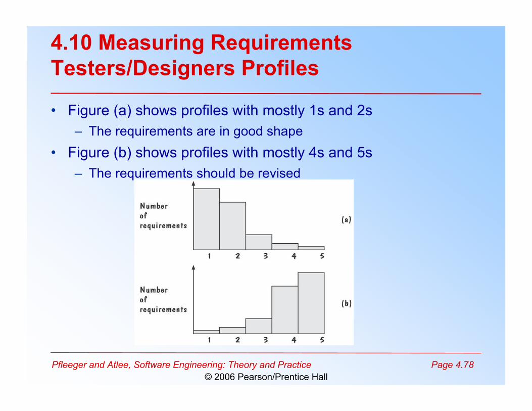
• Figure (a) shows profiles with mostly 1s and 2s– The requirements are in good shape
• Figure (b) shows profiles with mostly 4s and 5s– The requirements should be revised
Pfleeger and Atlee, Software Engineering: Theory and Practice Page 4.79© 2006 Pearson/Prentice Hall
4.11 Choosing a Specification Technique
• Note: Skipping Section 4.11
Pfleeger and Atlee, Software Engineering: Theory and Practice Page 4.80© 2006 Pearson/Prentice Hall
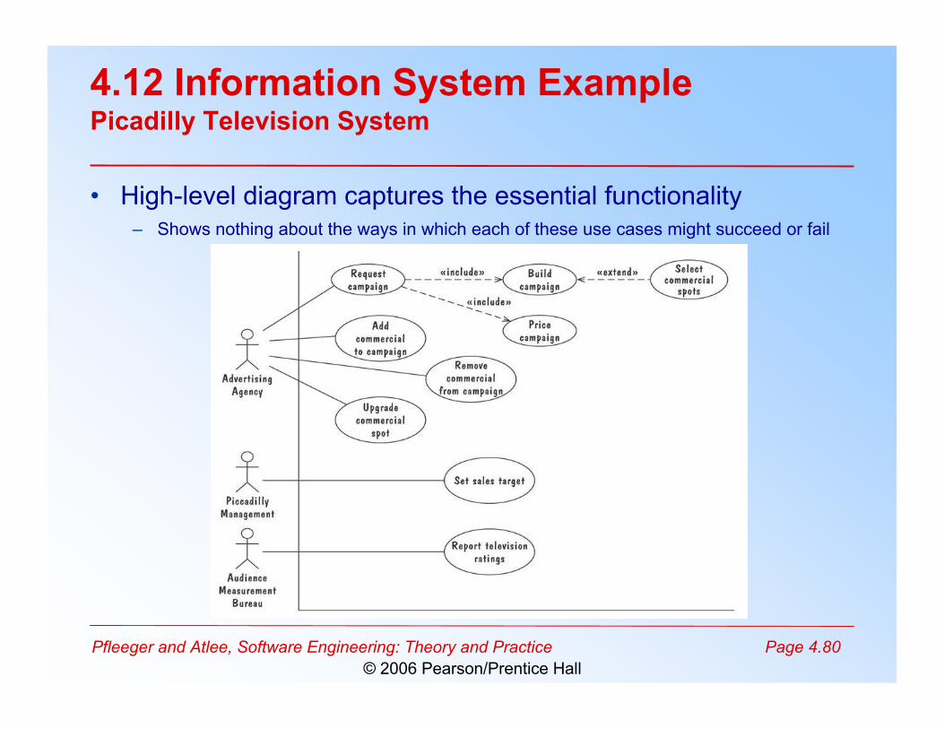
4.12 Information System ExamplePicadilly Television System
• High-level diagram captures the essential functionality– Shows nothing about the ways in which each of these use cases might succeed or fail
Pfleeger and Atlee, Software Engineering: Theory and Practice Page 4.81© 2006 Pearson/Prentice Hall
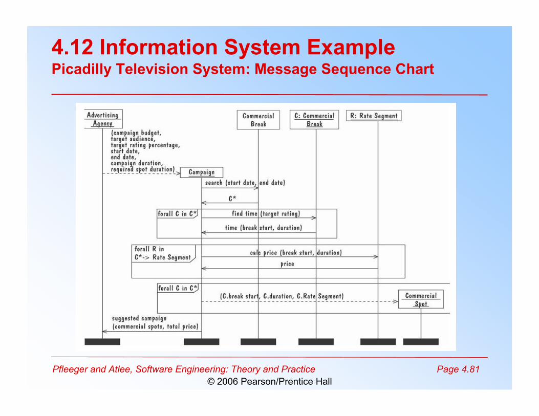
4.12 Information System ExamplePicadilly Television System: Message Sequence Chart
Pfleeger and Atlee, Software Engineering: Theory and Practice Page 4.82© 2006 Pearson/Prentice Hall
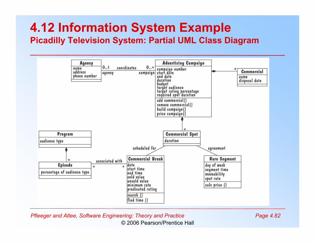
4.12 Information System ExamplePicadilly Television System: Partial UML Class Diagram
Pfleeger and Atlee, Software Engineering: Theory and Practice Page 4.83© 2006 Pearson/Prentice Hall
4.13 Real-Time Example
• Ariane-5 failed due to requirement validation notdone properly– Requirements validation could have played a crucial
role in preventing the rocket's explosion• Two criteria that are especially important for
specifying a system such as Ariane-5– Testability/simulation and runtime safety– SDL was rated “strong” for testability/simulation and
runtime safety
Pfleeger and Atlee, Software Engineering: Theory and Practice Page 4.84© 2006 Pearson/Prentice Hall
4.14 What This Chapter Means for You
• It is essential that the requirements definition and specificationdocuments describe the problem, leaving solution selection todesigner
• There is a variety of sources and means for eliciting requirements• There are many different types of definition and specification
techniques• The specification techniques also differ in terms of their tool support,
maturity, understandability, ease of use, and mathematical formality• Requirements questions can be answered using models or prototypes• Requirements must be validated to ensure that they accurately reflect
the customer's expectations