Csci 232 Computer NetworksSwitching and Forwarding1 Topics Interconnecting LAN segments –HUB...
77
Csci 232 Computer Networks Switching and Forwarding 1 Topics • Interconnecting LAN segments – HUB (Physical Layer) – Bridge (Link layer) – Layer 2 Switch (multi-port bridge, link layer) • Interconnecting networks – Layer 3 Switch (network layer) – Router (network layer) • ATM Networks
-
Upload
ashlynn-mckenzie -
Category
Documents
-
view
222 -
download
0
Transcript of Csci 232 Computer NetworksSwitching and Forwarding1 Topics Interconnecting LAN segments –HUB...
Csci 232 Computer Networks
Switching and Forwarding 1
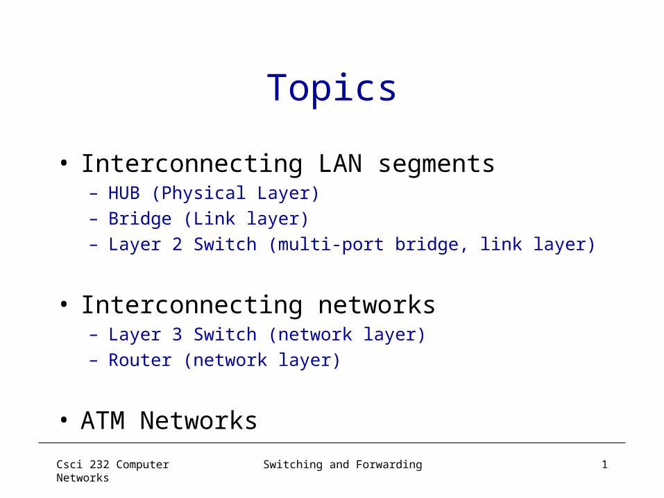
Topics
• Interconnecting LAN segments– HUB (Physical Layer)– Bridge (Link layer)– Layer 2 Switch (multi-port bridge, link layer)
• Interconnecting networks– Layer 3 Switch (network layer)– Router (network layer)
• ATM Networks

Csci 232 Computer Networks
Switching and Forwarding 2
Interconnecting LAN Segments• (Repeating) Hubs (layer 1 devices)• Bridges (layer 2 devices)
– Basic Functions– Self learning and bridge forwarding table– Forwarding/filtering algorithm– Bridge looping problem and spanning tree algorithm
• Ethernet Switches – Remark: switches are essentially multi-port bridges.– What we say about bridges also holds for switches!
• Readings– Section 3.2

Csci 232 Computer Networks
Switching and Forwarding 3
Interconnecting with Hubs• Backbone hub interconnects LAN segments• Extends max distance between nodes• But individual segment collision domains become one large collision
domain– if a node in CS and a node EE transmit at same time: collision
• Can’t interconnect 10BaseT & 100BaseT– Encoding is different: Manchester vs. 4B/5B
Recreates each bit,boosts its energy strength, and transmits the bit to all other interfaces

Csci 232 Computer Networks
Switching and Forwarding 4
Bridges
• Link layer device– stores and forwards Ethernet frames– examines frame header and selectively forwards
frame based on MAC destination address -- filtering– when frame is to be forwarded on a LAN segment,
uses CSMA/CD to access the LAN segment
• transparent– hosts are unaware of the presence of bridges
• plug-and-play, self-learning– bridges do not need to be configured

Csci 232 Computer Networks
Switching and Forwarding 5
Bridges: Traffic Isolation• Bridge installation breaks LAN into LAN
segments
• Bridges filter packets: – same-LAN-segment frames not usually forwarded
onto other LAN segments– segments become separate collision domains
bridge collision domain
collision domain
= hub
= host
LAN (IP network)
LAN segment LAN segment
Csci 232 Computer Networks
Switching and Forwarding 6
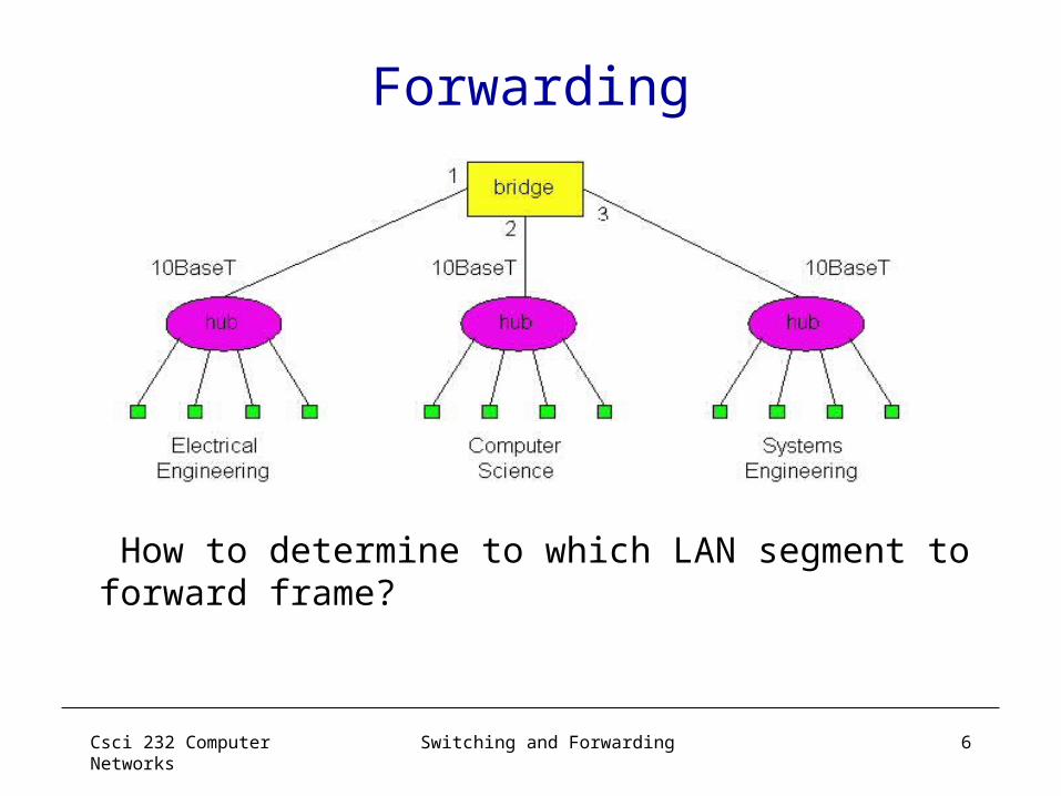
Forwarding
How to determine to which LAN segment to forward frame?

Csci 232 Computer Networks
Switching and Forwarding 7
Self Learning
• A bridge has a bridge (forwarding) table• Entry in bridge forwarding table:
– <Node LAN Address, Bridge Interface, Time Stamp>– stale entries in table dropped (TTL can be 60 min)
• Bridges learn which hosts can be reached through which interfaces– when frame received, bridge “learns” location of sender:
incoming LAN segment– records sender/location pair in bridge forwarding table

Csci 232 Computer Networks
Switching and Forwarding 8
Filtering/ForwardingWhen bridge receives a frame:
index bridge table using dest MAC addressif entry found for destination
then{ if dest on segment from which frame arrived
then drop the frame else forward the frame on interface indicated } else flood
forward on all but the interface on which the frame arrived

Csci 232 Computer Networks
Switching and Forwarding 9
Bridge ExampleSuppose C sends frame to D and D replies back
with a frame to C.
• Bridge receives frame from C– notes in bridge forwarding table that C is on interface 1– because D is not in table, bridge sends frame into
interfaces 2 and 3
• frame received by D

Csci 232 Computer Networks
Switching and Forwarding 10
Bridge Learning: Example
• D generates a frame for C, sends
• bridge receives the frame – notes in bridge forwarding table that D is on interface 2 – bridge knows C is on interface 1, so selectively forwards
frame to interface 1

Csci 232 Computer Networks
Switching and Forwarding 11
Interconnection without Backbone
• Not recommended for two reasons:- single point of failure at Computer Science hub- all traffic between EE and SE must path over CS segment

Csci 232 Computer Networks
Switching and Forwarding 12
Backbone Configuration
Recommended !
Csci 232 Computer Networks
Switching and Forwarding 13
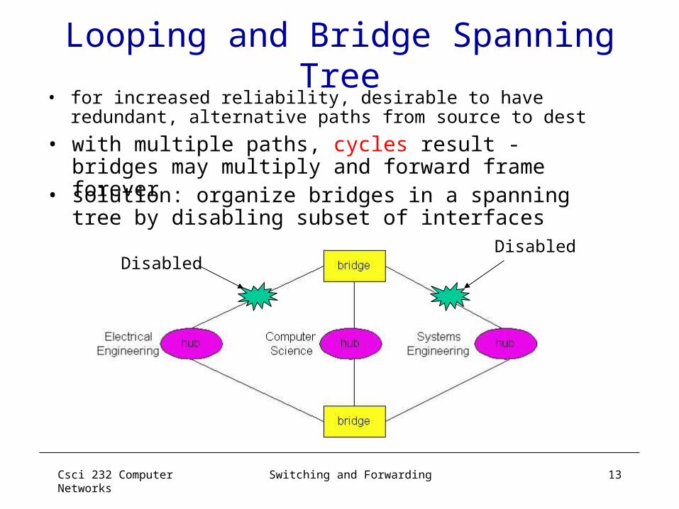
Looping and Bridge Spanning Tree
• for increased reliability, desirable to have redundant, alternative paths from source to dest
DisabledDisabled
• solution: organize bridges in a spanning tree by disabling subset of interfaces
• with multiple paths, cycles result - bridges may multiply and forward frame forever

Csci 232 Computer Networks
Switching and Forwarding 14
Bridge Spanning Tree Algorithm:Algorhyme
I think that I shall never seeA graph more lovely than a tree.A tree whose crucial propertyIs loop-free connectivity.A tree that must be sure to spanSo packets can reach every LAN.First, the root must be selected. By ID, it is elected.Least cost paths from root are traced.In the tree, these paths are placed.A mesh is made by folks like me,Then bridges find a spanning tree -- Radia Perlman
Csci 232 Computer Networks
Switching and Forwarding 15
Some Bridge Features• Isolates collision domains resulting in higher
total max throughput• “limitless” number of nodes and geographical
coverage– Scalable? (broadcast, spanning tree algorithm…)– Heterogeneity (understands one type of LAN address only)
• Can connect different Ethernet types • Transparent (“plug-and-play”): no
configuration necessary– Dropping packets? Long latency? Frames reordered?
Csci 232 Computer Networks
Switching and Forwarding 16
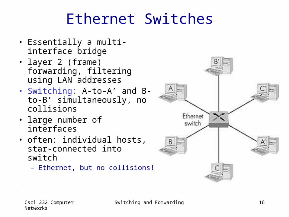
Ethernet Switches
• Essentially a multi-interface bridge
• layer 2 (frame) forwarding, filtering using LAN addresses
• Switching: A-to-A’ and B-to-B’ simultaneously, no collisions
• large number of interfaces• often: individual hosts,
star-connected into switch– Ethernet, but no collisions!

Csci 232 Computer Networks
Switching and Forwarding 17
Ethernet Switches
• cut-through switching: frame forwarded from input to output port without awaiting for assembly of entire frame– slight reduction in latency– Cut-through vs. store and forward
• combinations of shared/dedicated, 10/100/1000 Mbps interfaces
Csci 232 Computer Networks
Switching and Forwarding 18
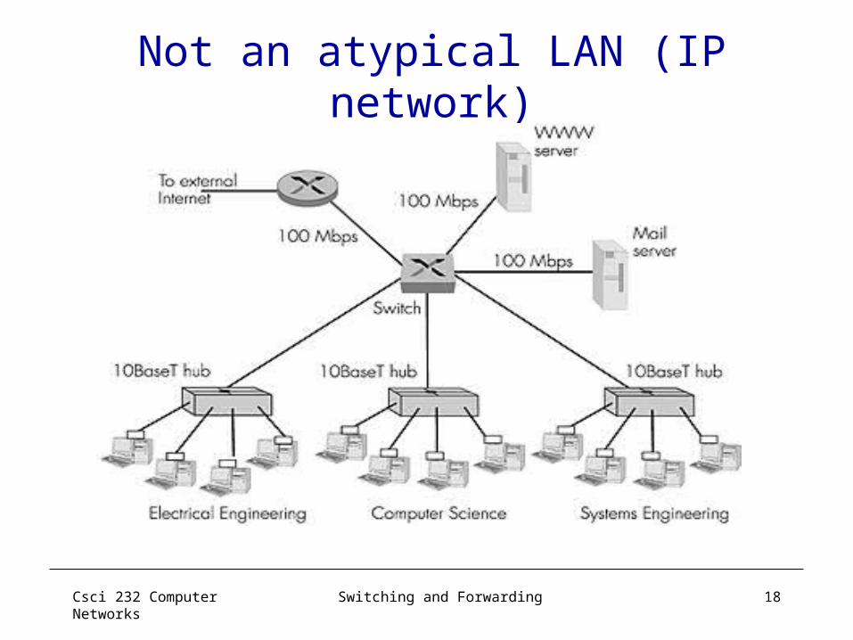
Not an atypical LAN (IP network)
Dedicated
Shared
Csci 232 Computer Networks
Switching and Forwarding 19
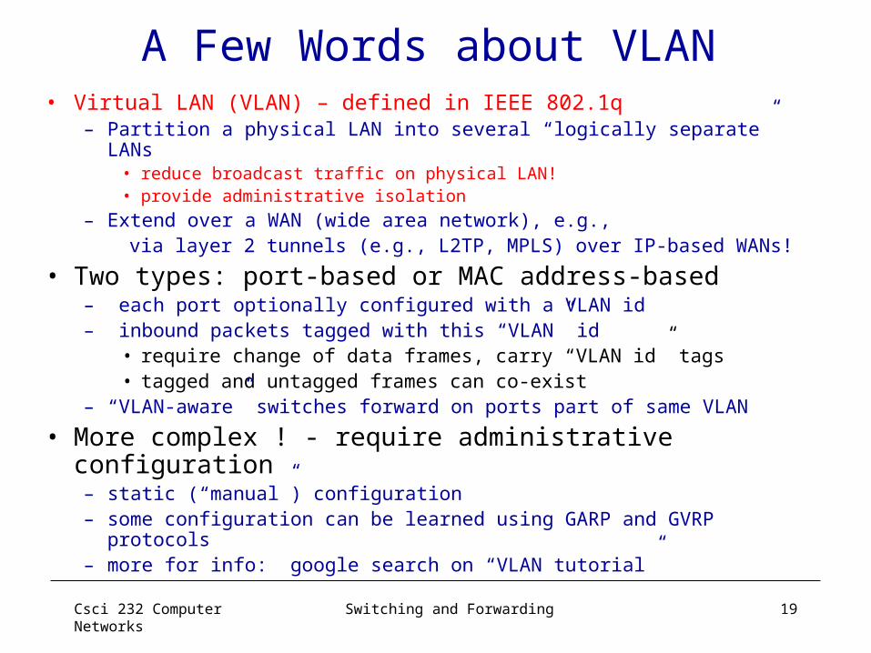
A Few Words about VLAN• Virtual LAN (VLAN) – defined in IEEE 802.1q
– Partition a physical LAN into several “logically separate” LANs• reduce broadcast traffic on physical LAN!• provide administrative isolation
– Extend over a WAN (wide area network), e.g., via layer 2 tunnels (e.g., L2TP, MPLS) over IP-based WANs!
• Two types: port-based or MAC address-based– each port optionally configured with a VLAN id– inbound packets tagged with this “VLAN” id
• require change of data frames, carry “VLAN id” tags• tagged and untagged frames can co-exist
– “VLAN-aware” switches forward on ports part of same VLAN
• More complex ! - require administrative configuration– static (“manual”) configuration– some configuration can be learned using GARP and GVRP
protocols– more for info: google search on “VLAN tutorial”
Csci 232 Computer Networks
Switching and Forwarding 20
Summary of LAN
• Local Area Networks– Designed for short distance– Use shared media– Many technologies exist
• Media Access Control: key problem!– Different environments/technologies-> different
solutions!
• Topology refers to general shape– Bus– Ring– Star
Csci 232 Computer Networks
Switching and Forwarding 21
Summary (continued)
• Address– Unique number assigned to station– Put in frame header– Recognized by hardware
• Address forms– Unicast– Broadcast– Multicast

Csci 232 Computer Networks
Switching and Forwarding 22
Summary (continued)
• Type information– Describes data in frame– Set by sender– Examined by receiver
• Frame format– Header contains address and type information– Payload contains data being sent

Csci 232 Computer Networks
Switching and Forwarding 23
Summary (continued)• LAN technologies
– Ethernet (bus)– Token Ring– FDDI (ring)– Wireless 802.11
• Wiring and topology– Logical topology and Physical topology (wiring)– Hub allows
• Star-shaped bus• Star-shaped ring

Csci 232 Computer Networks
Switching and Forwarding 24
Summary (cont’d) • Interconnecting LAN Segments
– (Repeating) Hubs– Bridges
• Self learning and bridge forwarding table• Forwarding/filtering algorithm• Bridge looping problem and spanning tree
algorithm
– (Layer-2) Switches• store and forward switching• cut-through switching

Csci 232 Computer Networks
Switching and Forwarding 25
Switching and ForwardingNetwork Layer
• Switching and Forwarding– Generic Switch Architecture – Forwarding Tables:
• Bridges/Layer 2 Switches; VLAN• Routers and Layer 3 Switches
• Forwarding in Layer 3 (Network Layer) – Network Layer Functions – Network Service Models: VC vs. Datagram
• ATM and IP Datagram Forwarding
Readings: Textbook: Chapter 3: Sections 3.1; 3.3-3.4
Csci 232 Computer Networks
Switching and Forwarding 26
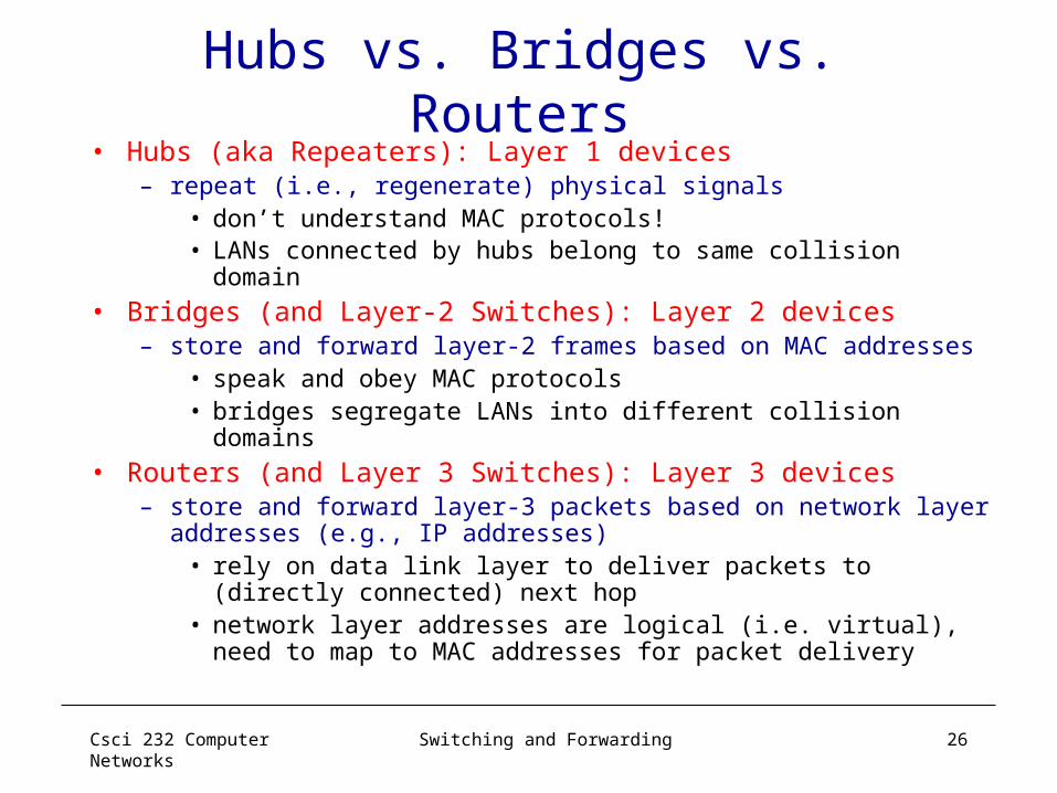
Hubs vs. Bridges vs. Routers• Hubs (aka Repeaters): Layer 1 devices
– repeat (i.e., regenerate) physical signals• don’t understand MAC protocols!• LANs connected by hubs belong to same collision domain
• Bridges (and Layer-2 Switches): Layer 2 devices– store and forward layer-2 frames based on MAC addresses
• speak and obey MAC protocols• bridges segregate LANs into different collision domains
• Routers (and Layer 3 Switches): Layer 3 devices– store and forward layer-3 packets based on network layer
addresses (e.g., IP addresses)• rely on data link layer to deliver packets to (directly
connected) next hop• network layer addresses are logical (i.e. virtual), need to
map to MAC addresses for packet delivery
Csci 232 Computer Networks
Switching and Forwarding 27
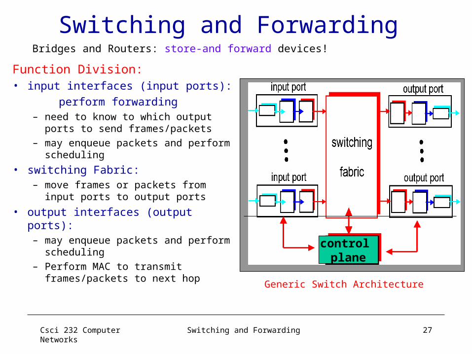
Switching and Forwarding
Function Division:• input interfaces (input ports): perform forwarding
– need to know to which output ports to send frames/packets
– may enqueue packets and perform scheduling
• switching Fabric: – move frames or packets from
input ports to output ports
• output interfaces (output ports):– may enqueue packets and
perform scheduling– Perform MAC to transmit
frames/packets to next hop Generic Switch Architecture
Bridges and Routers: store-and forward devices!
control plane

Csci 232 Computer Networks
Switching and Forwarding 28
Input Port Functions
Decentralized switching: • given datagram dest., lookup output
port using forwarding table in input port memory
• goal: complete input port processing at ‘line speed’
• queuing: if datagrams arrive faster than forwarding rate into switch fabric
Physical layer:bit-level reception
Data link layer:e.g., Ethernet
Csci 232 Computer Networks
Switching and Forwarding 29
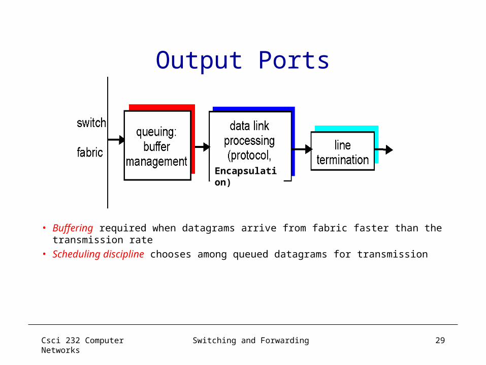
Output Ports
• Buffering required when datagrams arrive from fabric faster than the transmission rate
• Scheduling discipline chooses among queued datagrams for transmission
Encapsulation)
Csci 232 Computer Networks
Switching and Forwarding 30
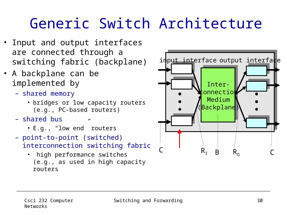
Generic Switch Architecture
input interface output interface
Inter-connection
Medium(Backplane)
C CRI ROB
• Input and output interfaces are connected through a switching fabric (backplane)
• A backplane can be implemented by– shared memory
• bridges or low capacity routers (e.g., PC-based routers)
– shared bus• E.g., “low end” routers
– point-to-point (switched) interconnection switching fabric
• high performance switches (e.g., as used in high capacity routers
Csci 232 Computer Networks
Switching and Forwarding 31
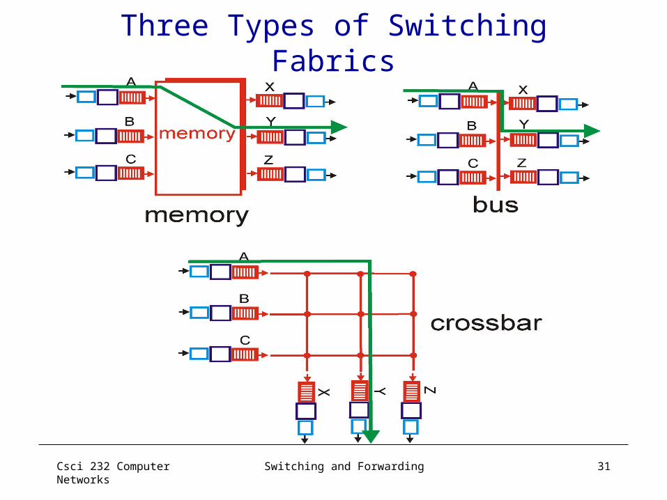
Three Types of Switching Fabrics

Csci 232 Computer Networks
Switching and Forwarding 32
Switching Via MemoryFirst generation routers:• traditional computers with switching under direct control of CPU•packet copied to system’s memory• speed limited by memory bandwidth (2 bus crossings per datagram)
InputPort
OutputPort
Memory
System Bus
Csci 232 Computer Networks
Switching and Forwarding 33
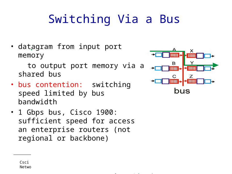
Switching Via a Bus
• datagram from input port memory
to output port memory via a shared bus
• bus contention: switching speed limited by bus bandwidth
• 1 Gbps bus, Cisco 1900: sufficient speed for access an enterprise routers (not regional or backbone)
Csci 232 Computer Networks
Switching and Forwarding 34
Switching Via An Interconnection Network
• overcome bus bandwidth limitations• Banyan networks, other interconnection nets
initially developed to connect processors in multiprocessor
• Advanced design: fragmenting datagram into fixed length cells, switch cells through the fabric.
• Cisco 12000: switches Gbps through the interconnection network

Csci 232 Computer Networks
Switching and Forwarding 35
Forwarding in Layer 3Putting in context• What does layer-3 (network layer) do?
– deliver packets “hop-by-hop” across a network– rely on layer-2 to deliver between neighboring hops
• Key Network Layer Functions– Addressing: need a global (logical) addressing scheme– Routing: build “map” of network, find routes, …– Forwarding: actual delivery of packets!
• Two basic network layer service models– datagram: “connectionless”– virtual circuit (VC): connection-oriented
Csci 232 Computer Networks
Switching and Forwarding 36
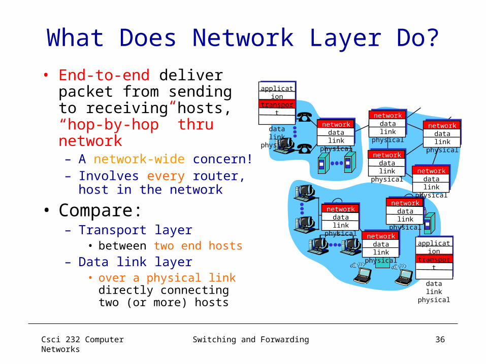
What Does Network Layer Do?• End-to-end deliver
packet from sending to receiving hosts, “hop-by-hop” thru network– A network-wide concern!– Involves every router,
host in the network
• Compare:– Transport layer
• between two end hosts– Data link layer
• over a physical link directly connecting two (or more) hosts
networkdata linkphysical
networkdata linkphysical
networkdata linkphysical
networkdata linkphysical
networkdata linkphysical
networkdata linkphysical
networkdata linkphysical
networkdata linkphysical
application
transportnetworkdata linkphysical
application
transportnetworkdata linkphysical
Csci 232 Computer Networks
Switching and Forwarding 37
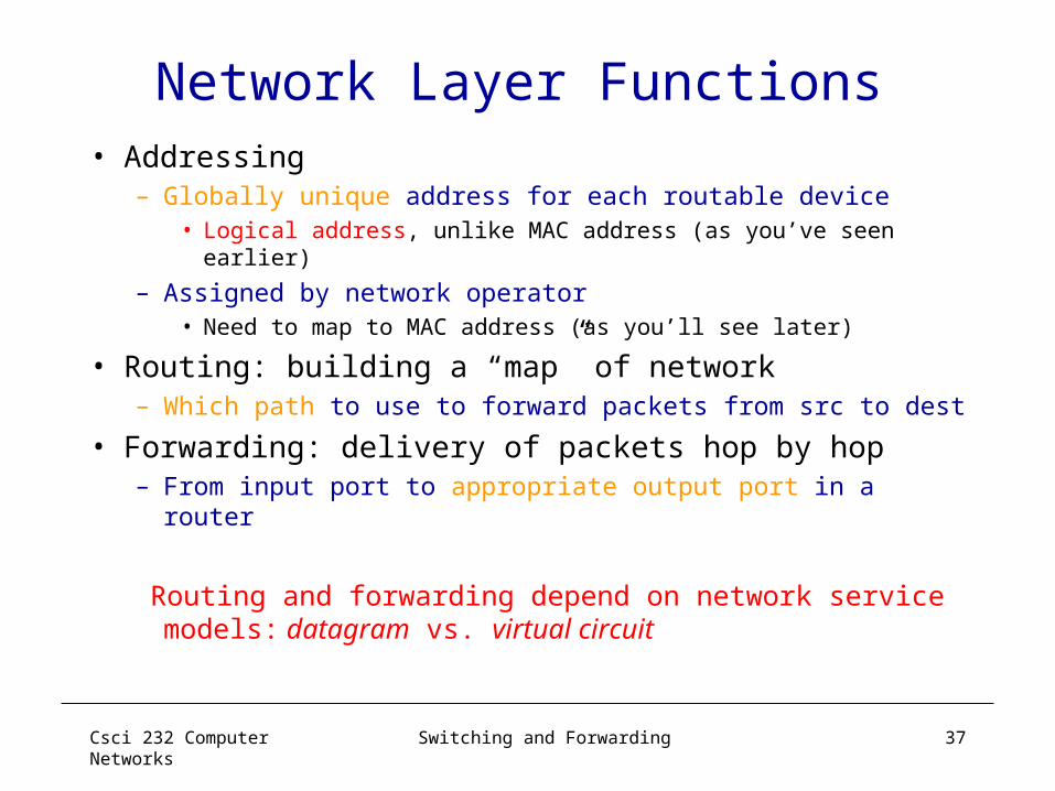
Network Layer Functions• Addressing
– Globally unique address for each routable device• Logical address, unlike MAC address (as you’ve seen
earlier)
– Assigned by network operator• Need to map to MAC address (as you’ll see later)
• Routing: building a “map” of network– Which path to use to forward packets from src to dest
• Forwarding: delivery of packets hop by hop– From input port to appropriate output port in a router
Routing and forwarding depend on network service models: datagram vs. virtual circuit

Csci 232 Computer Networks
Switching and Forwarding 38
Routing & Forwarding:Logical View of a Router
A
ED
CB
F
22
13
1
1
2
53
5
Csci 232 Computer Networks
Switching and Forwarding 39
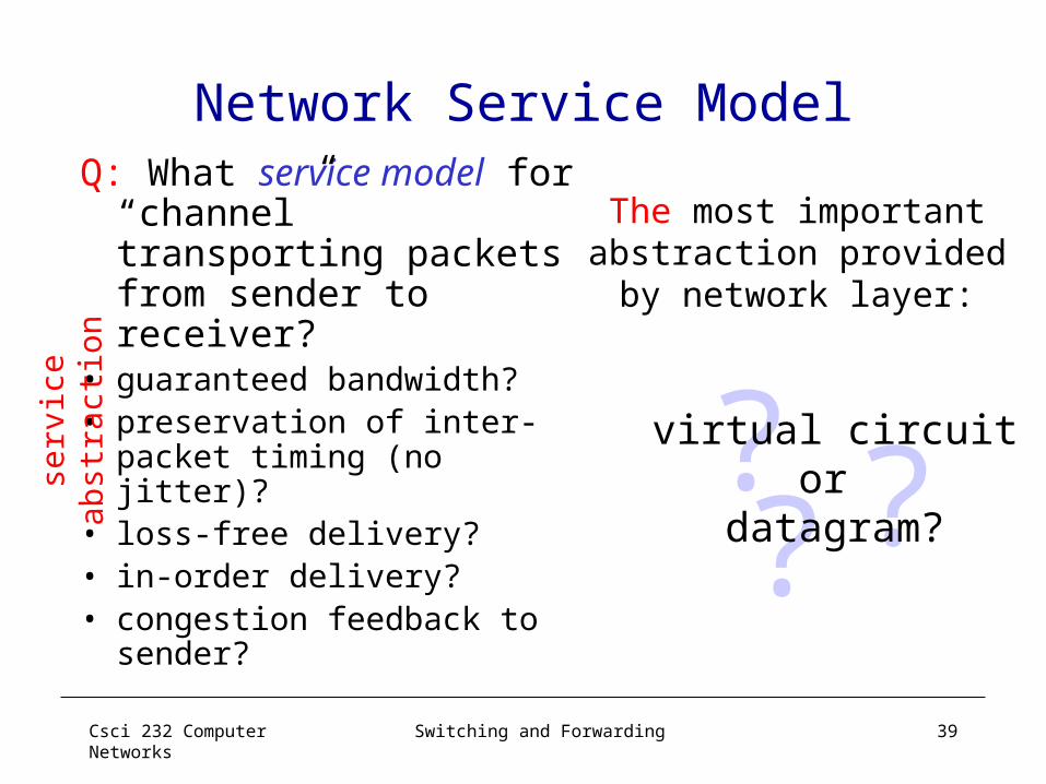
Network Service ModelQ: What service model
for “channel” transporting packets from sender to receiver?
• guaranteed bandwidth?• preservation of inter-
packet timing (no jitter)?• loss-free delivery?• in-order delivery?• congestion feedback to
sender?
? ??virtual circuit
or datagram?
The most important abstraction provided
by network layer:
serv
ice a
bst
ract
ion

Csci 232 Computer Networks
Switching and Forwarding 40
Virtual Circuit vs. Datagram• Objective of both: move packets through routers from
source to destination• Datagram Model:
– Routing: determine next hop to each destination a priori– Forwarding: destination address in packet header, used
at each hop to look up for next hop • routes may change during “session”
– analogy: driving, asking directions at every corner gas station, or based on the road signs at every turn
• Virtual Circuit Model: – Routing: determine a path from source to each
destination – “Call” Set-up: fixed path (“virtual circuit”) set up at
“call” setup time, remains fixed thru “call” – Data Forwarding: each packet carries “tag” or “label”
(virtual circuit id, VCI), which determines next hop– routers maintain ”per-call” state

Csci 232 Computer Networks
Switching and Forwarding 41
Virtual Circuit Switching• Explicit connection setup (and tear-
down) phase• Subsequence packets follow same
circuit• Sometimes called connection-oriented
modelstill packet switching, not circuit switching!
• Analogy: phone call
• Each switch maintains a VC table
2
0
1
2
3
0
1
2
3
0
13
0
1
2
3
Host A Host B
Switch 3
Switch 2Switch 1
75
4
11

Csci 232 Computer Networks
Switching and Forwarding 42
Datagram Switching
• No connection setup phase• Each packet forwarded independently • Sometimes called connectionless model
• Analogy: postal system
• Each switch maintains a forwarding (routing) table
0
132
0
1 3
2
013
2
Switch 3 Host B
Switch 2
Host A
Switch 1
Host C
Host D
Host EHost F
Host G
Host H

Csci 232 Computer Networks
Switching and Forwarding 43
Forwarding Tables: VC vs. Datagram
• Virtual Circuit Forwarding Table
a.k.a. VC (Translation) Table (switch 1, port 2)
• Datagram Forwarding Table
(switch 1)
Address PortA 2C 3F 1G 1… …
VC In VC Out Port Out
5 11 16 8 1
… … …

Csci 232 Computer Networks
Switching and Forwarding 44
More on Virtual Circuits
• call setup/teardown for each call before data can flow– need special control protocol: “signaling” – every router on source-dest path maintains “state”
(VCI translation table) for each passing call – VCI translation table at routers along the path of a
call “weaving together” a “logical connection” for the call
• link, router resources (bandwidth, buffers) may be reserved and allocated to each VC– to get “circuit-like” performance
“source-to-dest path behaves much like telephone circuit” (but actually over packet network)

Csci 232 Computer Networks
Switching and Forwarding 45
Virtual Circuit: Signaling Protocols
• used to setup, maintain teardown VC• used in ATM, frame-relay, X.25• used in part of today’s Internet: Multi-Protocol Label
Switching (MPLS) operated at “layer 2+1/2” (between data link layer and network layer) for “traffic engineering” purpose
application
transportnetworkdata linkphysical
application
transportnetworkdata linkphysical
1. Initiate call 2. incoming call
3. Accept call4. Call connected5. Data flow begins 6. Receive data

Csci 232 Computer Networks
Switching and Forwarding 46
Virtual Circuit Setup/TeardownCall Set-Up: • Source: select a path from source to destination
– Use routing table (which provides a “map of network”)• Source: send VC setup request control (“signaling”) packet
– Specify path for the call, and also the (initial) output VCI – perhaps also resources to be reserved, if supported
• Each router along the path:– Determine output port and choose a (local) output VCI for the call
• need to ensure that no two distinct VCs leaving the same output port have the same VCI!
– Update VCI translation table (“forwarding table”)• add an entry, establishing an mapping between incoming VCI
& port no. and outgoing VCI & port no. for the call
Call Tear-Down: similar, but remove entry instead
Csci 232 Computer Networks
Switching and Forwarding 47
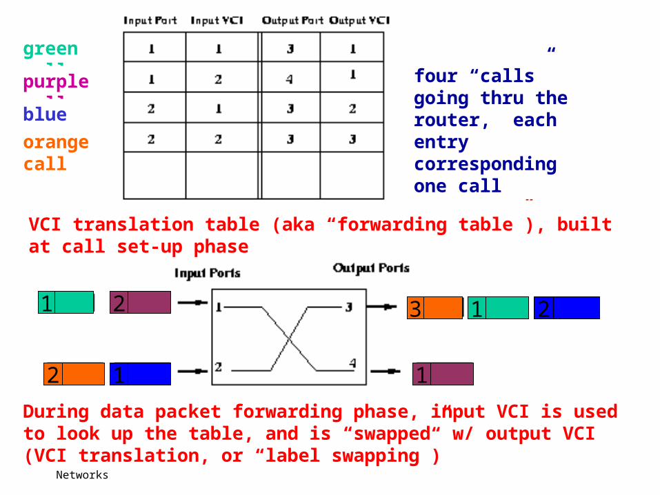
During data packet forwarding phase, input VCI is used to look up the table, and is “swapped” w/ output VCI (VCI translation, or “label swapping”)
VCI translation table (aka “forwarding table”), built at call set-up phase
1
2
13
1
2 2
1
four “calls” going thru the router, each entry corresponding one call
green call
purple call
blue call
orange call
Csci 232 Computer Networks
Switching and Forwarding 48
Virtual Circuit: Example
0
13
2
0
1 3
2
0
13
2
511
4
7
Router 3
Host B
Router 2
Host A
Router 1
Router 4
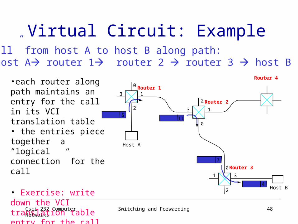
“call” from host A to host B along path: host A router 1 router 2 router 3 host B
•each router along path maintains an entry for the call in its VCI translation table• the entries piece together a “logical connection” for the call
• Exercise: write down the VCI translation table entry for the call at each router

Csci 232 Computer Networks
Switching and Forwarding 49
Virtual Circuit Model: Pros and Cons
• Full RTT for connection setup– before sending first data packet.
• Setup request carries full destination address– each data packet contains only a small identifier
• If a switch or a link in a connection fails– new connection needs to be established.
• Provides opportunity to reserve resources.

Csci 232 Computer Networks
Switching and Forwarding 50
ATM Networks
• Asynchronous Transfer Mode– Single technology for handling voice,video, and data
• Connection-oriented service using virtual circuits– In-sequence but unreliable
• Cell switching using fixed-size cells: 53 bytes– Statistical multiplexing of cells of different circuits
• Provide QoS guarantees/assurance– Variety of services such as CBR, VBR, ABR etc

Csci 232 Computer Networks
Switching and Forwarding 51
Variable vs Fixed-Length Packets
• No optimal length– if small: high header-to-data overhead– if large: low utilization for small messages
• Fixed-Length easier to switch in hardware– simpler– enables parallelism

Csci 232 Computer Networks
Switching and Forwarding 52
Big vs Small Packets• Small Improves Queue behavior
– finer-grained pre-emption point for scheduling link• maximum packet = 4KB• link speed = 100Mbps• transmission time = 4096 x 8/100 = 327.68us• high priority packet may sit in the queue 327.68us• in contrast, 53 x 8/100 = 4.24us for ATM
– near cut-through behavior • two 4KB packets arrive at same time• link idle for 327.68us while both arrive• at end of 327.68us, still have 8KB to transmit • in contrast, can transmit first cell after 4.24us• at end of 327.68us, just over 4KB left in queue
Csci 232 Computer Networks
Switching and Forwarding 53
Big vs Small (cont)
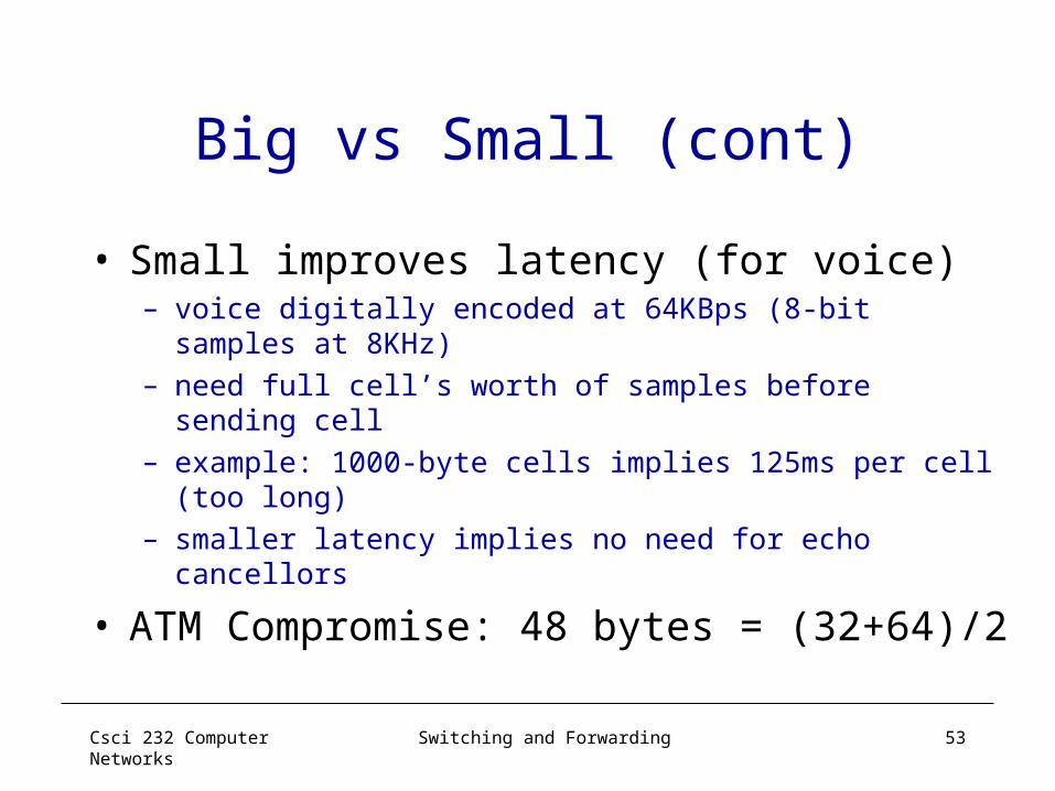
• Small improves latency (for voice) – voice digitally encoded at 64KBps (8-bit samples at
8KHz)– need full cell’s worth of samples before sending cell– example: 1000-byte cells implies 125ms per cell (too
long)– smaller latency implies no need for echo cancellors
• ATM Compromise: 48 bytes = (32+64)/2
Csci 232 Computer Networks
Switching and Forwarding 54
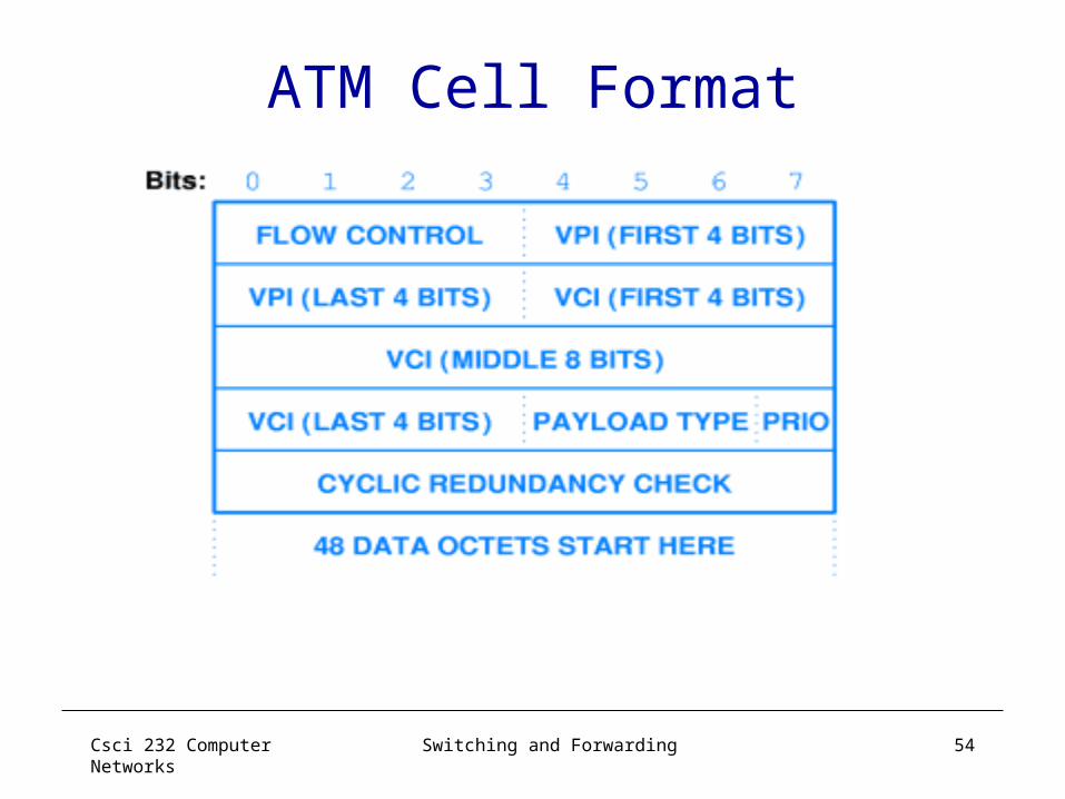
ATM Cell Format

Csci 232 Computer Networks
Switching and Forwarding 55
More on Cell Format• User-Network Interface (UNI)
– host-to-switch format – GFC: Generic Flow Control (still being defined)– VCI: Virtual Circuit Identifier– VPI: Virtual Path Identifier– Type: management, congestion control, AAL5 (later, type field
contains a user signaling bit to identify the end of a PDU )– CLPL Cell Loss Priority – HEC: Header Error Check (CRC-8)
• Network-Network Interface (NNI)– switch-to-switch format– GFC becomes part of VPI field
GFC HEC (CRC-8)
4 16 3 18
VPI VCI CLPType Payload
384 (48 bytes)8
Csci 232 Computer Networks
Switching and Forwarding 56
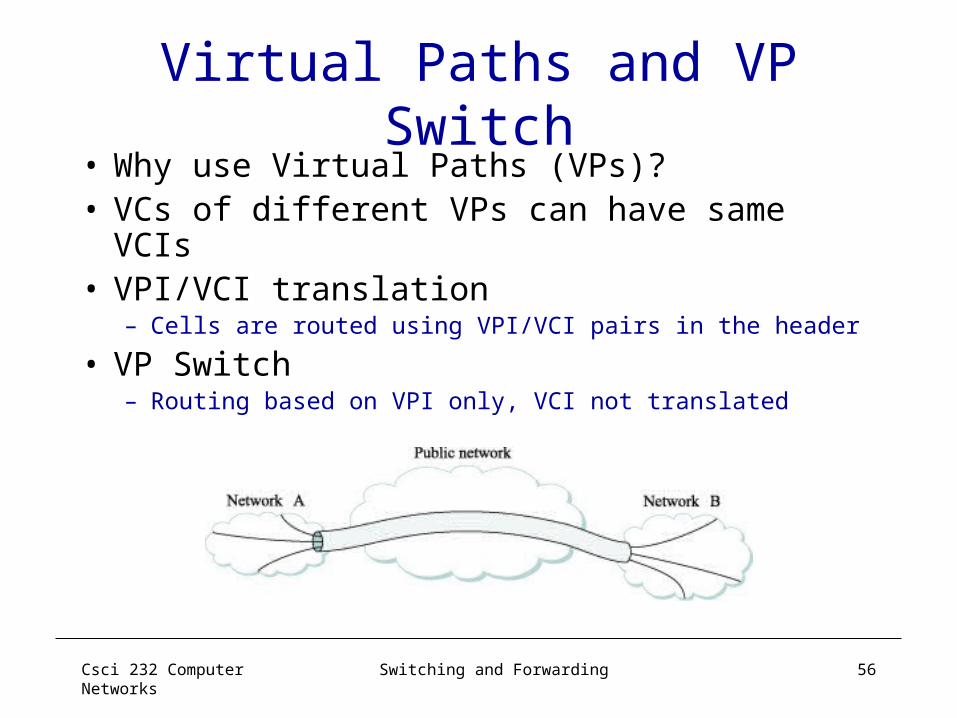
Virtual Paths and VP Switch• Why use Virtual Paths (VPs)? • VCs of different VPs can have same VCIs• VPI/VCI translation
– Cells are routed using VPI/VCI pairs in the header
• VP Switch– Routing based on VPI only, VCI not translated

Csci 232 Computer Networks
Switching and Forwarding 57
Segmentation and Reassembly
• ATM Adaptation Layer (AAL)– Sets above ATM layer and below the layer with variable
length frame– AAL 1 and 2 designed for applications that need
guaranteed rate (e.g., voice, video)– AAL 3/4 designed for packet data– AAL 5 is an alternative standard for packet data
■ ■ ■ ■ ■ ■
AAL
ATM
AAL
ATM

Csci 232 Computer Networks
Switching and Forwarding 58
AAL 3/4
• Convergence Sublayer Protocol Data Unit (CS-PDU) – encapsulation before segmentation
– CPI: common part indicator (version field)– Btag/Etag: beginning and ending tag– BAsize: hint on amount of buffer space to allocate – Length: size of whole PDU
CPI Btag BASize Pad 0 Etag Len
8 16 0─24 8 8 16< 64 KB8
User data
Csci 232 Computer Networks
Switching and Forwarding 59
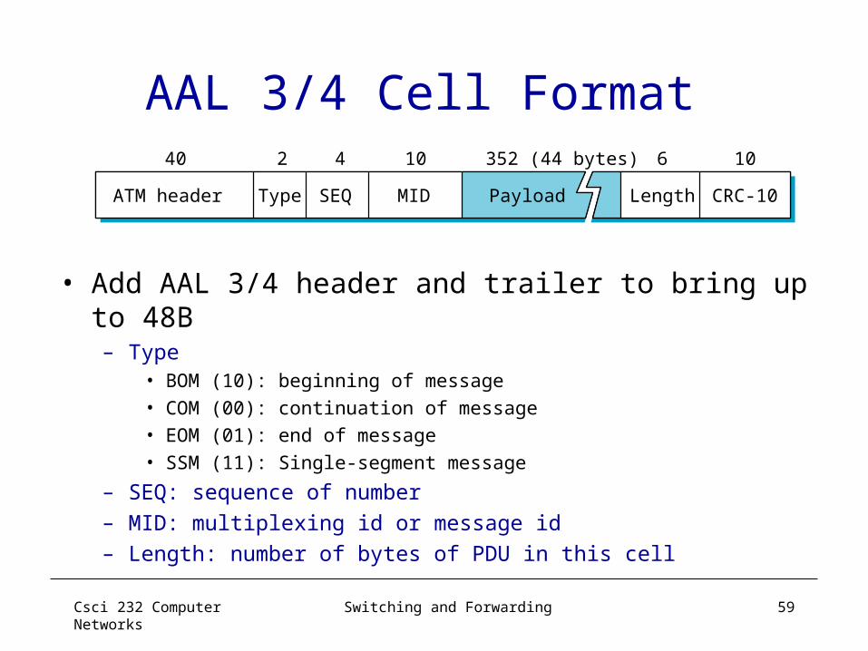
AAL 3/4 Cell Format
• Add AAL 3/4 header and trailer to bring up to 48B– Type
• BOM (10): beginning of message • COM (00): continuation of message• EOM (01): end of message• SSM (11): Single-segment message
– SEQ: sequence of number – MID: multiplexing id or message id– Length: number of bytes of PDU in this cell
ATM header Length CRC-10
40 2 4
SEQ MIDType Payload
352 (44 bytes)10 6 10

Csci 232 Computer Networks
Switching and Forwarding 60
Encapsulation and Segmentation for AAL 3/4

Csci 232 Computer Networks
Switching and Forwarding 61
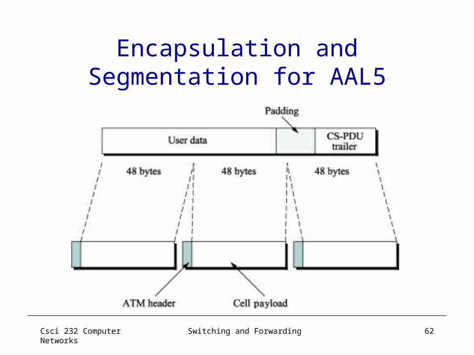
AAL5• CS-PDU Format
– pad so trailer always falls at end of ATM cell– Length: size of PDU (data only)– CRC-32 (detects missing or misordered cells)
• Cell Format– end-of-PDU bit in Type field of ATM header
CRC-32
< 64 KB 0─47 bytes 16 16
ReservedPad Len
32
Data
Csci 232 Computer Networks
Switching and Forwarding 62
Encapsulation and Segmentation for AAL5
Csci 232 Computer Networks
Switching and Forwarding 63
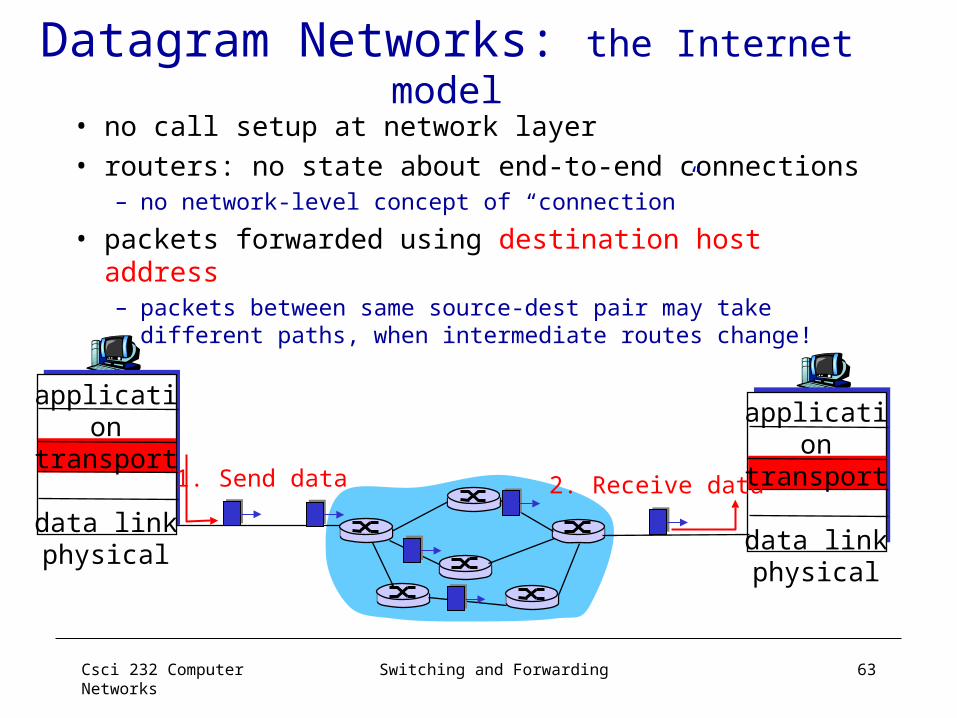
Datagram Networks: the Internet model
• no call setup at network layer• routers: no state about end-to-end connections
– no network-level concept of “connection”
• packets forwarded using destination host address– packets between same source-dest pair may take
different paths, when intermediate routes change!
application
transportnetworkdata linkphysical
application
transportnetworkdata linkphysical
1. Send data 2. Receive data

Csci 232 Computer Networks
Switching and Forwarding 64
Datagram Model• There is no round trip delay waiting for connection setup; a
host can send data as soon as it is ready.
• Source host has no way of knowing if the network is capable of delivering a packet or if the destination host is even up.
• Since packets are treated independently, it is possible to route around link and node failures.
• Since every packet must carry the full address of the destination, the overhead per packet is higher than for the connection-oriented model.
Csci 232 Computer Networks
Switching and Forwarding 65
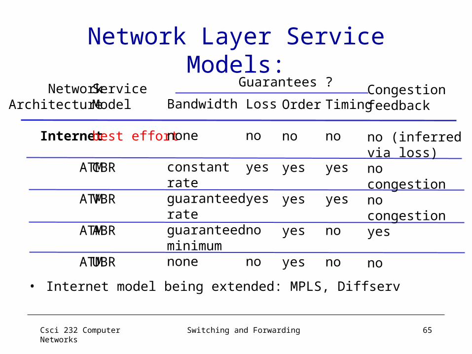
Network Layer Service Models:
NetworkArchitecture
Internet
ATM
ATM
ATM
ATM
ServiceModel
best effort
CBR
VBR
ABR
UBR
Bandwidth
none
constantrateguaranteedrateguaranteed minimumnone
Loss
no
yes
yes
no
no
Order
no
yes
yes
yes
yes
Timing
no
yes
yes
no
no
Congestionfeedback
no (inferredvia loss)nocongestionnocongestionyes
no
Guarantees ?
• Internet model being extended: MPLS, Diffserv

Csci 232 Computer Networks
Switching and Forwarding 66
Datagram or VC: Why?Internet• data exchange among
computers– “elastic” service, no
strict timing req. • “smart” end systems
(computers)– can adapt, perform
control, error recovery– simple inside network,
complexity at “edge”• many link types
– different characteristics– uniform service difficult
ATM• evolved from telephony• human conversation:
– strict timing, reliability requirements
– need for guaranteed service
• “dumb” end systems– telephones– complexity inside
network

Csci 232 Computer Networks
Switching and Forwarding 67
Forwarding and Switching Network Layer Summary
• Switching and Forwarding– Generic Switch Architecture – Forwarding Tables:
• Bridges/Layer 2 Switches; VLAN• Routers and Layer 3 Switches
• Network Service (Forwarding) Models– Virtual Circuit vs. Datagram– Virtual Circuit Model: ATM example
• VC set-up/tear-down• data forward operations
Csci 232 Computer Networks
Switching and Forwarding 68
More on Router ArchitectureThree Typical Architectures• Output queued• Input queued • Combined Input-Output queued
Csci 232 Computer Networks
Switching and Forwarding 69
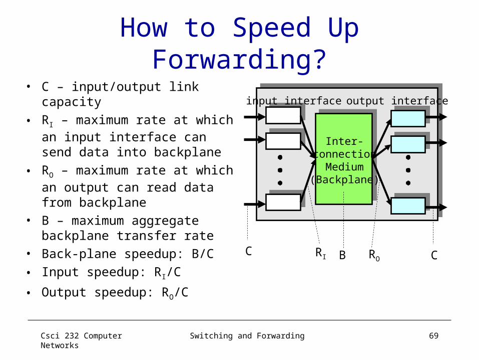
How to Speed Up Forwarding?
• C – input/output link capacity
• RI – maximum rate at which an input interface can send data into backplane
• RO – maximum rate at which an output can read data from backplane
• B – maximum aggregate backplane transfer rate
• Back-plane speedup: B/C
• Input speedup: RI/C
• Output speedup: RO/C
input interface output interface
Inter-connection
Medium(Backplane)
C CRI ROB

Csci 232 Computer Networks
Switching and Forwarding 70
Output Queued (OQ) Routers
• Only output interfaces store packets– buffering when arrival
rate via switch exceeds output line speed
– queueing (delay) and loss due to output port buffer overflow!
input interface output interface
Backplane
CRO
• Advantages– Easy to design algorithms: only one congestion
point
• Disadvantages– Requires an output speedup of N, where N is the
number of interfaces not feasible
B

Csci 232 Computer Networks
Switching and Forwarding 71
Input Queued Routers: Pros & Cons
• Advantages– Easy to built
• Store packets at inputs if contention at outputs
– Relatively easy to design algorithms• Only one congestion point, but not
output…• need to implement backpressure
• Disadvantages– Head-of-line (HOL) blocking– In general, hard to achieve high
utilization
input interface output interface
Backplane
CRI B
RO
C
Csci 232 Computer Networks
Switching and Forwarding 72
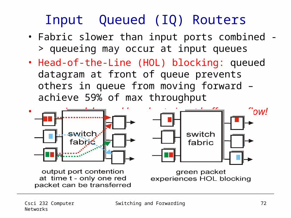
Input Queued (IQ) Routers• Fabric slower than input ports combined ->
queueing may occur at input queues • Head-of-the-Line (HOL) blocking: queued
datagram at front of queue prevents others in queue from moving forward – achieve 59% of max throughput
• queueing delay and loss due to input buffer overflow!
Csci 232 Computer Networks
Switching and Forwarding 73
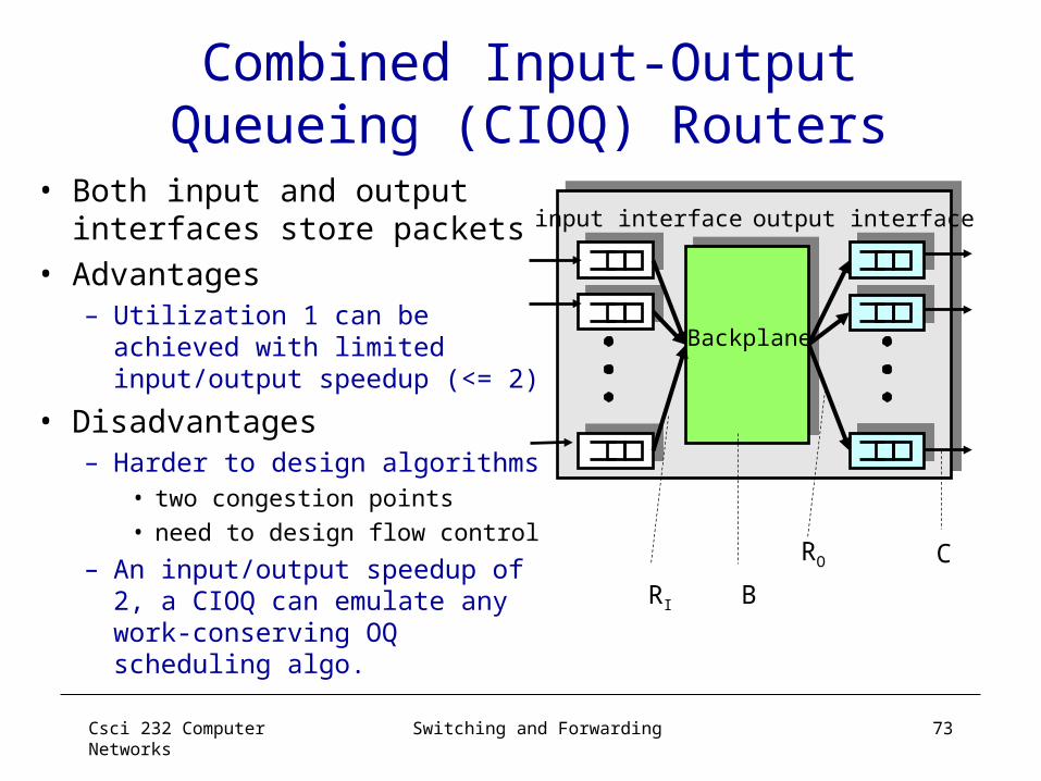
Combined Input-Output Queueing (CIOQ) Routers
• Both input and output interfaces store packets
• Advantages– Utilization 1 can be achieved
with limited input/output speedup (<= 2)
• Disadvantages– Harder to design algorithms
• two congestion points• need to design flow control
– An input/output speedup of 2, a CIOQ can emulate any work-conserving OQ scheduling algo.
input interface output interface
Backplane
CRO
RI B
Csci 232 Computer Networks
Switching and Forwarding 74
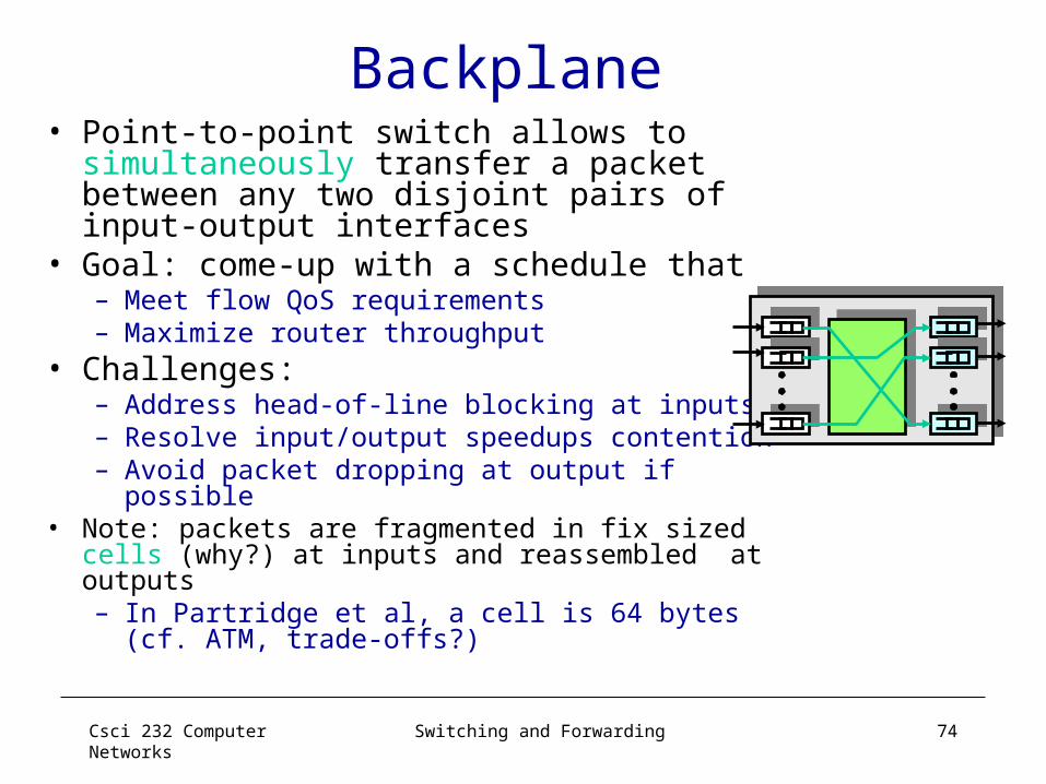
Backplane • Point-to-point switch allows to
simultaneously transfer a packet between any two disjoint pairs of input-output interfaces
• Goal: come-up with a schedule that– Meet flow QoS requirements– Maximize router throughput
• Challenges:– Address head-of-line blocking at inputs– Resolve input/output speedups contention– Avoid packet dropping at output if possible
• Note: packets are fragmented in fix sized cells (why?) at inputs and reassembled at outputs – In Partridge et al, a cell is 64 bytes (cf.
ATM, trade-offs?)

Csci 232 Computer Networks
Switching and Forwarding 75
Head-of-Line Blocking Revisited• The cell at head of an input queue cannot be
transferred, thus blocking the following cells
Cannot betransferred because output buffer full
Cannot be transferred because is blocked by red cell
Output 1
Output 2
Output 3
Input 1
Input 2
Input 3
Csci 232 Computer Networks
Switching and Forwarding 76
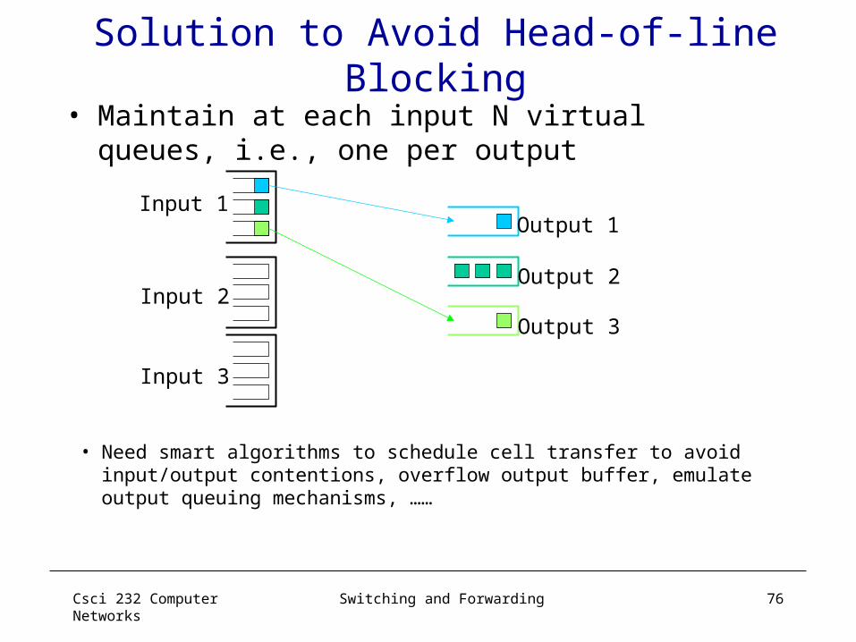
Solution to Avoid Head-of-line Blocking
• Maintain at each input N virtual queues, i.e., one per output
Output 1
Output 2
Output 3
Input 1
Input 2
Input 3
• Need smart algorithms to schedule cell transfer to avoid input/output contentions, overflow output buffer, emulate output queuing mechanisms, ……
Csci 232 Computer Networks
Switching and Forwarding 77
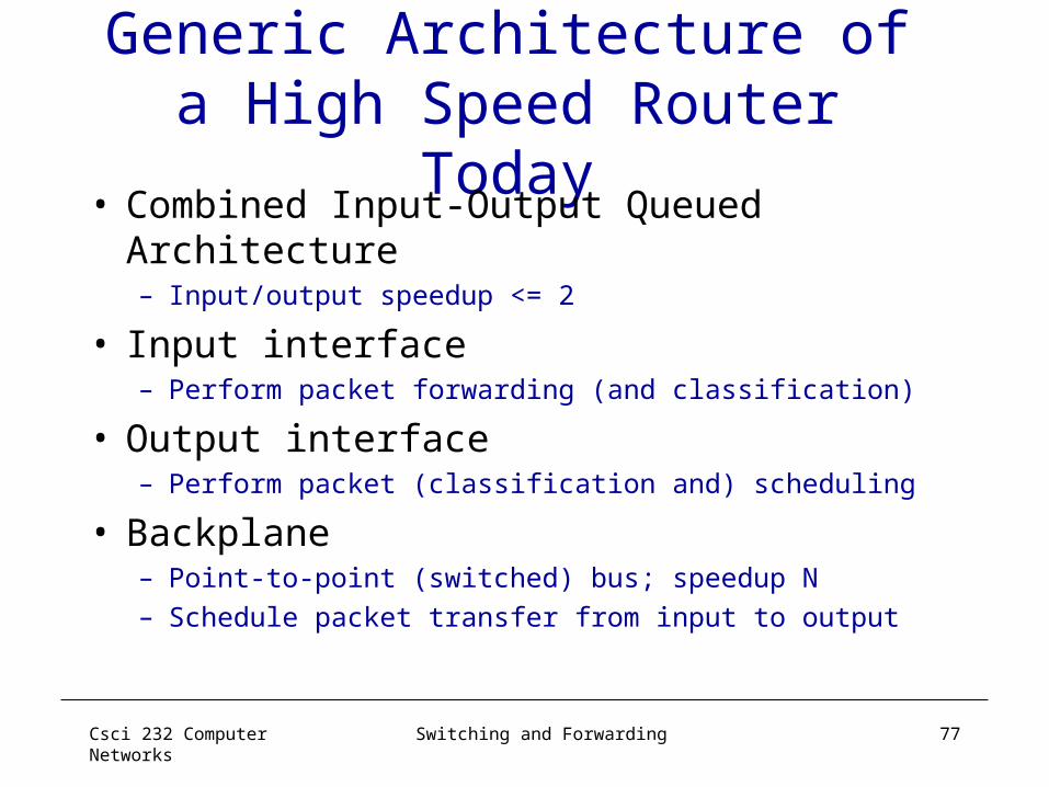
Generic Architecture of a High Speed Router Today
• Combined Input-Output Queued Architecture– Input/output speedup <= 2
• Input interface– Perform packet forwarding (and classification)
• Output interface– Perform packet (classification and) scheduling
• Backplane– Point-to-point (switched) bus; speedup N– Schedule packet transfer from input to output