CSCI-1680 Physical Layer Link Layer Ics.brown.edu/courses/csci1680/f14/lectures/03-phy.pdf ·...
37
CSCI-1680 Physical Layer Link Layer I Based partly on lecture notes by David Mazières, Phil Levis, John Janno< Rodrigo Fonseca
-
Upload
truongthuy -
Category
Documents
-
view
219 -
download
0
Transcript of CSCI-1680 Physical Layer Link Layer Ics.brown.edu/courses/csci1680/f14/lectures/03-phy.pdf ·...

CSCI-1680 Physical Layer
Link Layer I
Based partly on lecture notes by David Mazières, Phil Levis, John Janno<
Rodrigo Fonseca

Administrivia
• Snowcast milestone today! – 4-7pm – Sign up at http://tinyurl.com/cs168-calendar

Today
• Physical Layer – Modulation and Channel Capacity – Encoding
• Link Layer I – Framing

Layers, Services, Protocols
Network
Link
Physical
Transport
ApplicaBon
Service: move bits to other node across link
Service: move frames to other node across link. May add reliability, medium access control
Service: move packets to any other node in the network IP: Unreliable, best-‐effort service model
Service: mulBplexing applicaBons Reliable byte stream to other node (TCP), Unreliable datagram (UDP)
Service: user-‐facing applicaBon. ApplicaBon-‐defined messages

Physical Layer (Layer 1)
• Responsible for specifying the physical medium – Type of cable, fiber, wireless frequency
• Responsible for specifying the signal (modulation) – Transmitter varies something (amplitude, frequency, phase) – Receiver samples, recovers signal
• Responsible for specifying the bits (encoding) – Bits above physical layer -> chips
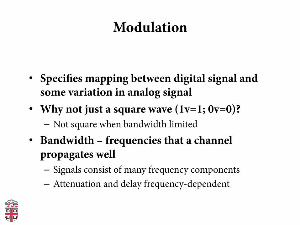
Modulation
• Specifies mapping between digital signal and some variation in analog signal
• Why not just a square wave (1v=1; 0v=0)? – Not square when bandwidth limited
• Bandwidth – frequencies that a channel propagates well – Signals consist of many frequency components – Attenuation and delay frequency-dependent

Components of a Square Wave
Graphs from Dr. David Alciatore, Colorado State University

Graphs from Dr. David Alciatore, Colorado State University
Approximation of a Square Wave

Idea: Use Carriers
• Only use frequencies that transmit well • Modulate the signal to encode bits
Specifying the Signal: Modulation
On-Off Keying
(OOK)
1 0 1
Amplitude Shift
Keying (ASK)
1 0 1
Specifying the Signal: Modulation
On-Off Keying
(OOK)
1 0 1
Amplitude Shift
Keying (ASK)
1 0 1
OOK: On-Off Keying ASK: Amplitude Shift Keying

Modulation, Continued
Frequency Shift
Keying (FSK)
1 0 1
Phase Shift
Keying (PSK)
1 0 1
Idea: Use Carriers
• Only use frequencies that transmit well • Modulate the signal to encode bits
FSK: Frequency Shift Keying PSK: Phase Shift Keying Modulation, Continued
Frequency Shift
Keying (FSK)
1 0 1
Phase Shift
Keying (PSK)
1 0 1
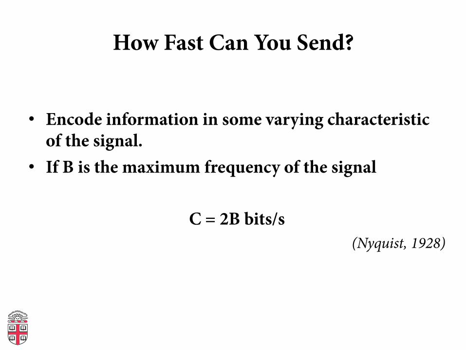
How Fast Can You Send?
• Encode information in some varying characteristic of the signal.
• If B is the maximum frequency of the signal
C = 2B bits/s (Nyquist, 1928)

Can we do better?
• So we can only change 2B/second, what if we encode more bits per sample? – Baud is the frequency of changes to the physical channel – Not the same thing as bits!
• Suppose channel passes 1KHz to 2KHz – 1 bit per sample: alternate between 1KHz and 2KHz – 2 bits per sample: send one of 1, 1.33, 1.66, or 2KHz – Or send at different amplitudes: A/4, A/2, 3A/4, A – n bits: choose among 2n frequencies!
• What is the capacity if you can distinguish M levels?

Example
Phase

Hartley’s Law
C = 2B log2(M) bits/s
Great. By increasing M, we can have as large a capacity as we want!
Or can we?

The channel is noisy!

• Noise prevents you from increasing M arbitrarily!
• This depends on the signal/noise ratio (S/N) • Shannon: C = B log2(1 + S/N)
– C is the channel capacity in bits/second – B is the bandwidth of the channel in Hz – S and N are average signal and noise power – Signal-to-noise ratio is measured in dB = 10log10(S/N)
The channel is noisy!

Putting it all together
• Noise limits M! 2B log2(M) ≤ B log2(1 + S/N)
M ≤ √1+S/N • Example: Telephone Line
– 3KHz b/w, 30dB S/N = 10ˆ(30/10) = 1000 – C = 3KHz log2(1001) ≈ 30Kbps

Encoding • Now assume that we can somehow modulate a
signal: receiver can decode our binary stream • How do we encode binary data onto signals? • One approach: 1 as high, 0 as low!
– Called Non-return to Zero (NRZ) 0 0 1 0 1 0 1 1 0
NRZ (non-‐return to zero)
Clock

Drawbacks of NRZ
• No signal could be interpreted as 0 (or vice-versa) • Consecutive 1s or 0s are problematic • Baseline wander problem – How do you set the threshold? – Could compare to average, but average may drift
• Clock recovery problem – For long runs of no change, could miscount periods

Alternative Encodings
• Non-return to Zero Inverted (NRZI) – Encode 1 with transition from current signal – Encode 0 by staying at the same level – At least solve problem of consecutive 1s
0 0 1 0 1 0 1 1 0
Clock
NRZI (non-‐return to zero
intverted)

Manchester
• Map 0 à chips 01; 1 à chips 10 – Transmission rate now 1 bit per two clock cycles
• Solves clock recovery, baseline wander • But cuts transmission rate in half
0 0 1 0 1 0 1 1 0
Clock
Manchester

4B/5B
• Can we have a more efficient encoding? • Every 4 bits encoded as 5 chips • Need 16 5-bit codes:
– selected to have no more than one leading 0 and no more than two trailing 0s
– Never get more than 3 consecutive 0s • Transmit chips using NRZI • Other codes used for other purposes
– E.g., 11111: line idle; 00100: halt • Achieves 80% efficiency

4B/5B Table

Encoding Goals
• DC Balancing (same number of 0 and 1 chips) • Clock synchronization • Can recover some chip errors • Constrain analog signal patterns to make signal more
robust • Want near channel capacity with negligible errors – Shannon says it’s possible, doesn’t tell us how – Codes can get computationally expensive
• In practice – More complex encoding: fewer bps, more robust – Less complex encoding: more bps, less robust

Last Example: 802.15.4
• Standard for low-power, low-rate wireless PANs – Must tolerate high chip error rates
• Uses a 4B/32B bit-to-chip encoding
802.15.4
• Standard for low-rate wireless personal networks- Must tolerate high chip error rates
• Uses a 32-to-4 chip-to-bit encoding
0011
0010
0001
0000
1111
1 1 0 1 1 0 0 1 1 1 0 0 0 0 1 1 0 1 0 1 0 0 1 0 0 0 1 0 1 1 1 0
1 1 1 0 1 1 0 1 1 0 0 1 1 1 0 0 0 0 1 1 0 1 0 1 0 0 1 0 0 0 1 0
0 0 1 0 1 1 1 0 1 1 0 1 1 0 0 1 1 1 0 0 0 0 1 1 0 1 0 1 0 0 1 0
0 0 1 0 0 0 1 0 1 1 1 0 1 1 0 1 1 0 0 1 1 1 0 0 0 0 1 1 0 1 0 1
1 1 0 0 1 0 0 1 0 1 1 0 0 0 0 0 0 1 1 1 0 1 1 1 1 0 1 1 1 0 0 0
Bits Chips
Symbols

Questions so far?
Photo: Lewis Hine

Today
• Physical Layer – Modulation and Channel Capacity – Encoding
• Link Layer I – Framing

Layers, Services, Protocols
Network
Link
Physical
Transport
ApplicaBon
Service: move bits to other node across link
Service: move frames to other node across link. May add reliability, medium access control
Service: move packets to any other node in the network IP: Unreliable, best-‐effort service model
Service: mulBplexing applicaBons Reliable byte stream to other node (TCP), Unreliable datagram (UDP)
Service: user-‐facing applicaBon. ApplicaBon-‐defined messages

Framing
• Given a stream of bits, how can we represent boundaries?
• Break sequence of bits into a frame • Typically done by network adaptor
Frames
Bits
Node A Node BAdaptor Adaptor

Link Layer Framing

Representing Boundaries
• Sentinels • Length counts • Clock-based
Frames
Bits
Node A Node BAdaptor Adaptor

Sentinel-based Framing
• Byte-oriented protocols (e.g. BISYNC, PPP) – Place special bytes (SOH, ETX,…) in the beginning, end of
messages
• What if ETX appears in the body? – Escape ETX byte by prefixing DEL byte – Escape DEL byte by prefixing DEL byte – Technique known as character stuffing
SY
N
Header Body
8 8 8 8 168
SY
N
SO
H
ST
X
ET
X
CRC

Bit-Oriented Protocols
• View message as a stream of bits, not bytes • Can use sentinel approach as well (e.g., HDLC)
– HDLC begin/end sequence 01111110 • Use bit stuffing to escape 01111110
– Always append 0 after five consecutive 1s in data – After five 1s, receiver uses next two bits to decide if
stuffed, end of frame, or error.
Header Body
8 16 16 8
CRCBeginningsequence
Endingsequence

Length-based Framing
• Drawback of sentinel techniques – Length of frame depends on data
• Alternative: put length in header (e.g., DDCMP)
• Danger: Framing Errors – What if high bit of counter gets corrupted? – Adds 8K to length of frame, may lose many frames – CRC checksum helps detect error
SY
N
Header Body
8 8 4214 168
SY
N
Cla
ss
CRCCount

Clock-based Framing • E.g., SONET (Synchronous Optical Network)
– Each frame is 125μs long – Look for header every 125μs – Encode with NRZ, but first XOR payload with 127-bit
string to ensure lots of transitions Overhead Payload
90 columns
9 rows
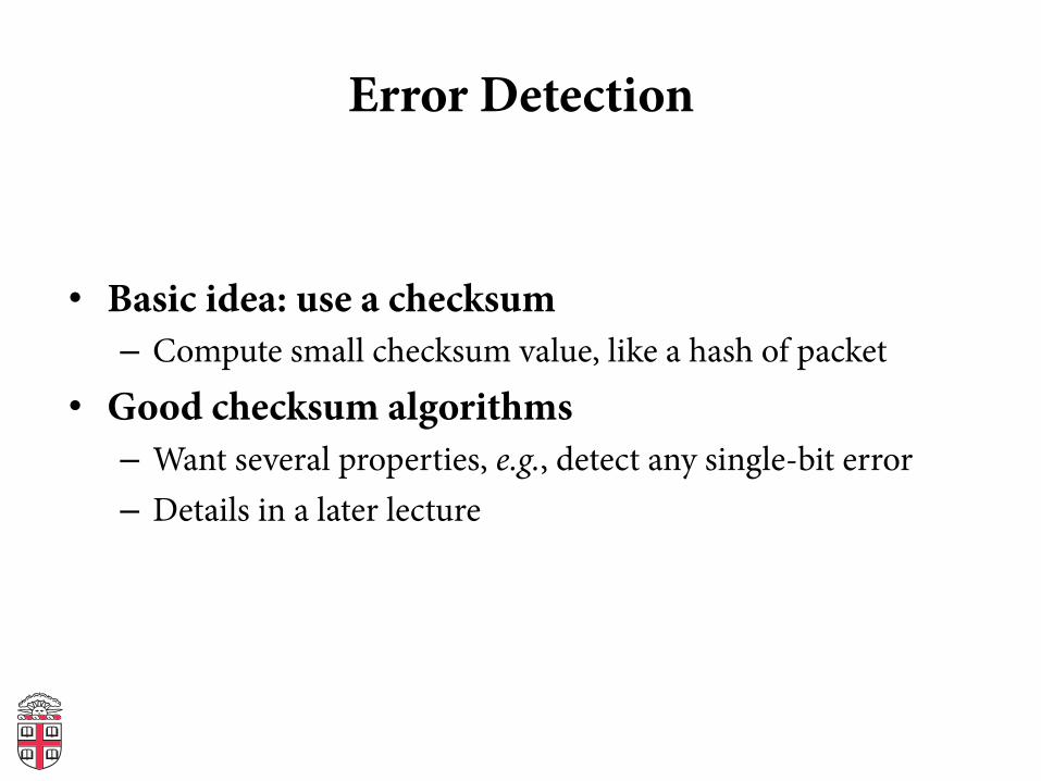
Error Detection
• Basic idea: use a checksum – Compute small checksum value, like a hash of packet
• Good checksum algorithms – Want several properties, e.g., detect any single-bit error – Details in a later lecture

Next Week
• Next week: more link layer – Flow Control and Reliability – Ethernet – Sharing access to a shared medium – Switching
• Thursday Sep 20th: Snowcast due, HW1 out