CS Colloquium Research Projects in Wireless Communication Networks Xin Liu Computer Sciences...
48
CS Colloquium Research Projects in Wireless Communication Networks Xin Liu Computer Sciences Department University of California, Davis
-
date post
22-Dec-2015 -
Category
Documents
-
view
221 -
download
4
Transcript of CS Colloquium Research Projects in Wireless Communication Networks Xin Liu Computer Sciences...

CS Colloquium
Research Projects in Wireless Communication Networks
Xin Liu
Computer Sciences Department
University of California, Davis

2
Wireless Networks
Cellular systems 1G: analog 2G: digital 3G: data
Wireless LAN IEEE 802.11
Ad-hoc wireless networks Military, emergency, etc.
Wireless Sensor networks

3
Research Topics
Digital signal processing Smart antenna Scheduling Power management Topology management Mobility management Routing (for ad hoc networks) ……

4
Unique Features
Motivated by some unique features in wireless communication systems:
Scarce radio resource Limited power Timing-varying channel conditions Shared media

5
Scarce Radio Resource
Wireline networks High bandwidth and reliable channel Core router: Gbps-Tbps
Wireless systems Limited nature resource (radio frequency) Capacity is limited by available frequency 3G data rate: up to 2Mbps IEEE 802.11b: up to 11Mbps Requirement: spectrum efficiency
6
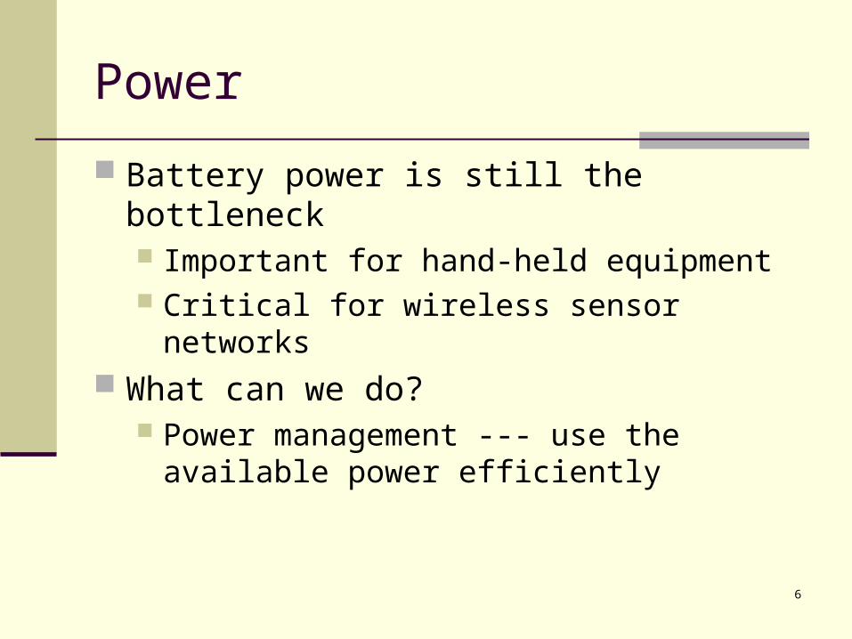
Power
Battery power is still the bottleneck Important for hand-held equipment Critical for wireless sensor networks
What can we do? Power management --- use the available
power efficiently

7
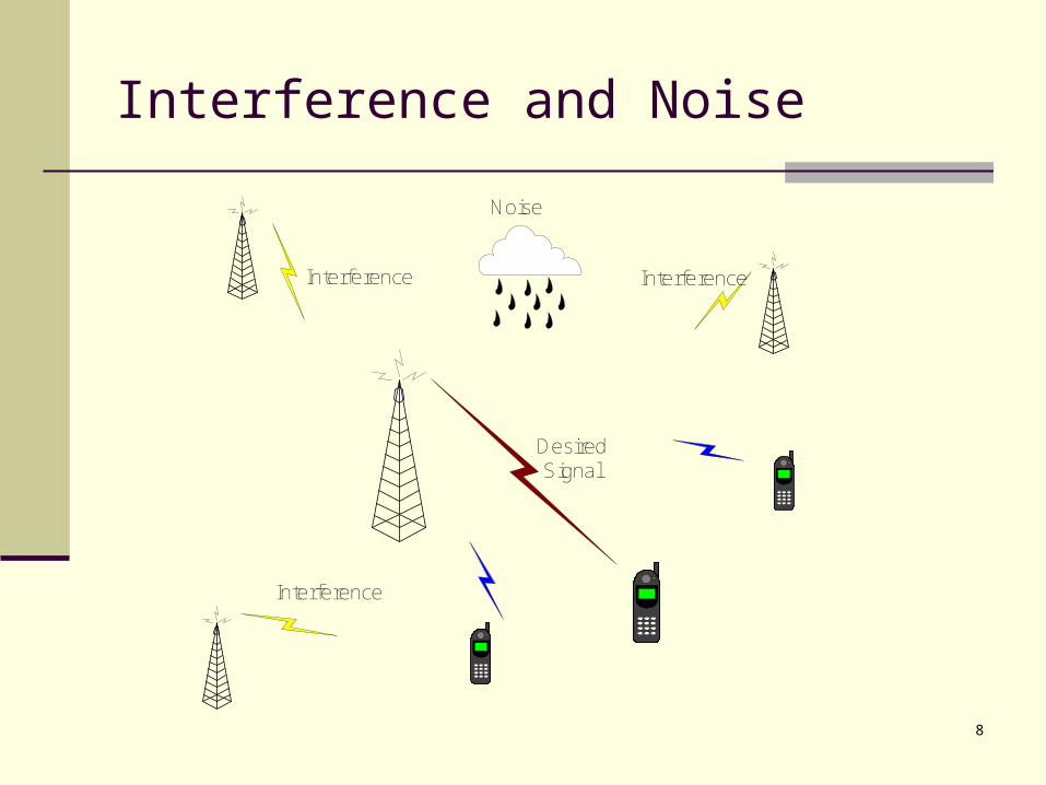
Channel Conditions
Decides transmission performance
Determined by Strength of desired signal Noise level
Interference from other transmissions Background noise
Time-varying and location-dependent.
8
Interference and Noise
Noise
Interference
Interference
Interference
DesiredSignal

9
Propagation Environment
Shadowing
Multi-path Fading
Strong
Weak
Path Loss

10
Time-varying Channel Conditions
Due to users’ mobility and variability in the propagation environment, both desired signal and interference are time-varying and location-dependent
A measure of channel quality:
SINR (Signal to Interference plus Noise Ratio)

11
Illustration of Channel Conditions
Based on Lee’s path loss model, log-normal shadowing, and Raleigh fading
12
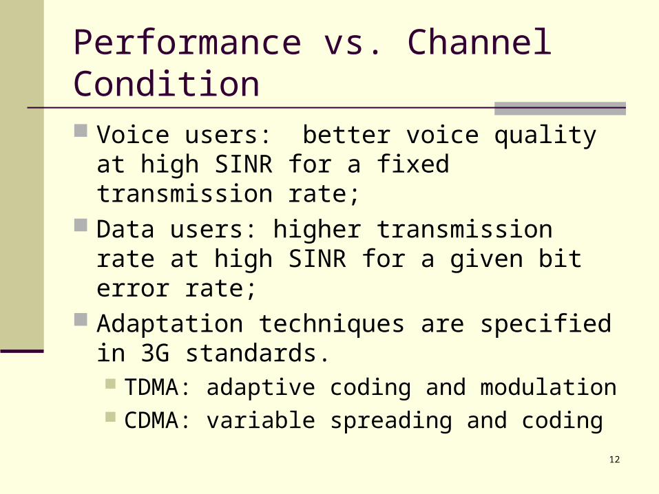
Performance vs. Channel Condition
Voice users: better voice quality at high SINR for a fixed transmission rate;
Data users: higher transmission rate at high SINR for a given bit error rate;
Adaptation techniques are specified in 3G standards. TDMA: adaptive coding and modulation CDMA: variable spreading and coding

13
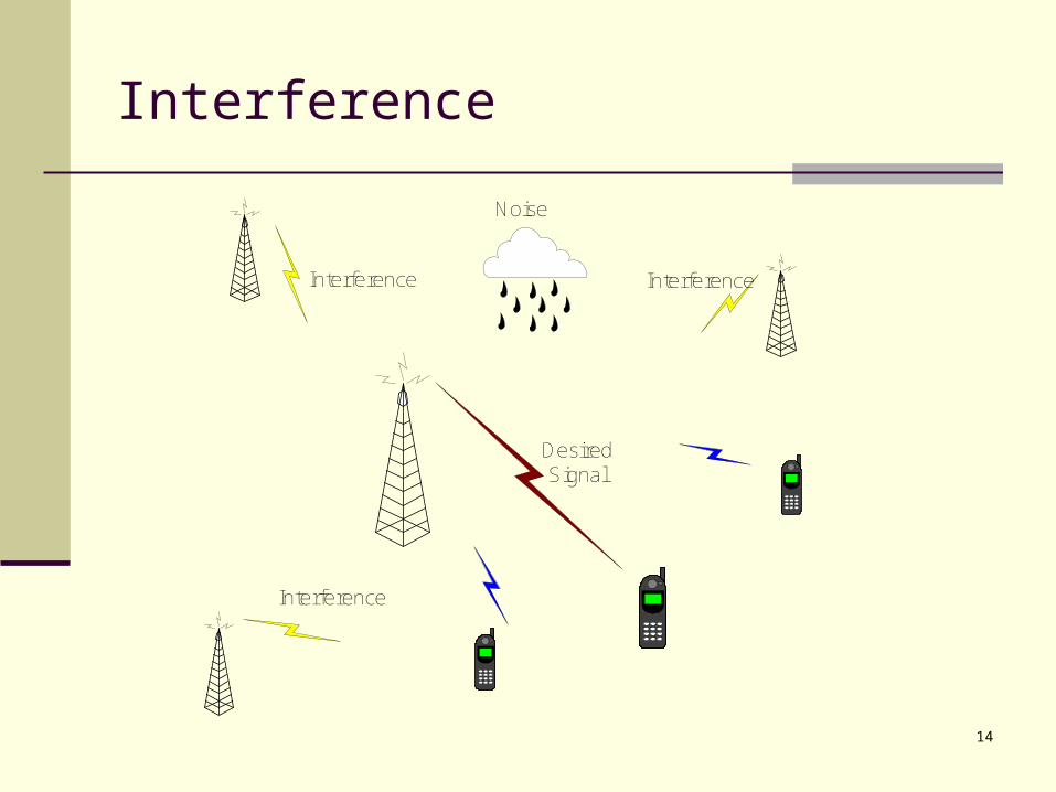
Shared Media
Shared media: everyone can hear each other
Can hurt Can help Multi-user diversity
14
Interference
Noise
Interference
Interference
Interference
DesiredSignal

15
Helper
Relay:
Coherent Relay:

16
Multi-user Diversity
Radio tower
Laptop
Radio tower
Different users see different channels at different time

17
Opportunistic scheduling
Motivation: Spectrum efficiency Time-varying channel
conditions Multi-user diversity
Question: how to handle channel variability?

18
Opportunism
Traditional design: point to point Channel variability: source of unreliability
Opportunism: embrace channel variability Multiple users share resource Exploits favorable channel conditions.

19
Myopic Opportunism
Greedy algorithm: best user to transmit Good throughput Unfairness
Starvation
20
Opportunistic Scheduling
Basic idea: schedule users in a way that exploits variability in channel conditions.
Opportunistic: choose a user to transmit when its channel condition is good.
Fairness/QoS requirements: opportunism cannot be too greedy.
Each scheduling decision depends on channel conditions fairness or QoS requirements.

21
System Model
Time-slotted systems
Each user has a certain requirement.
TDMA or time-slotted CDMA systems (e.g., IS-856, known as Qualcomm HDR)
Both uplink and downlink.
Time

22
Overview
EstimateUtility
Values
ApplyScheduling
Polity
UpdateParameters
MeasureChannel
Conditions
iU
iV

23
Performance Measure
Based on utility value Reflects channel condition. Uik : utility value of user i at time k .
If time slot k is assigned to user i, user i will receive a utility value of Uik.
Measures the worth of the time slot to user i. Examples of utility:
Throughput Throughput – cost of power consumption.
Utility values are comparable and additive.

24
Utility Values
{Uik, k=1,2,3…} is a stochastic process.
25
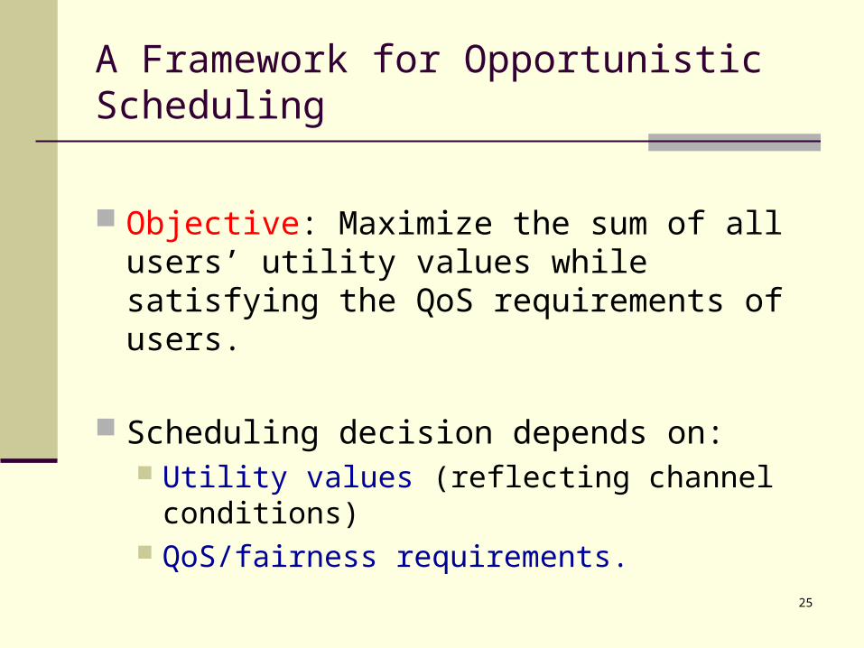
A Framework for Opportunistic Scheduling
Objective: Maximize the sum of all users’ utility values while satisfying the QoS requirements of users.
Scheduling decision depends on: Utility values (reflecting channel conditions) QoS/fairness requirements.
26
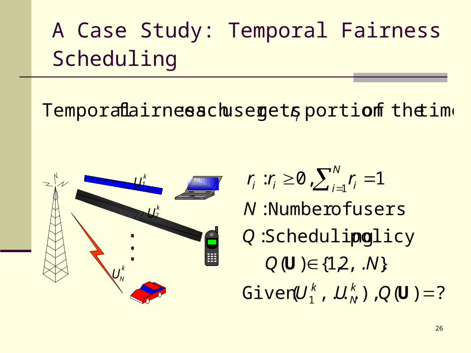
A Case Study: Temporal Fairness Scheduling
Uk1
Uk
N
Uk2
?)( ),,...(Given
},...2,1{)(
policy Scheduling :
users ofNumber :
1 0, :
1
1
U
U
QUU
NQ
Q
N
rrr
kN
k
N
i iii
time. theofportion getsuser each :fairness Temporal ir

27
Objective
Maximize average system utility subject to the
fairness constraints ri. System utility:
28
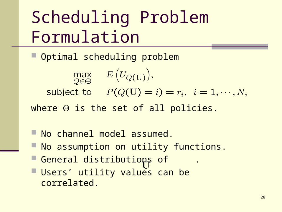
Scheduling Problem Formulation
Optimal scheduling problem
where is the set of all policies.
No channel model assumed. No assumption on utility functions. General distributions of . Users’ utility values can be correlated.

29
An Optimal Scheduling Policy
Choose the ``relatively-best'' user to transmit.
vi* : “off-sets” used to achieve the fairness requirement.

30
Property
Improves performance for all.
Gain depends on channel variability.
A certain level of average utility guarantee for each user.
31
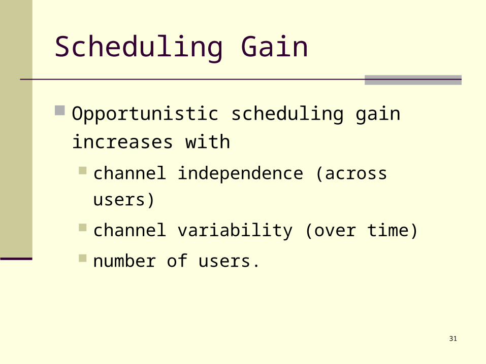
Scheduling Gain
Opportunistic scheduling gain increases with
channel independence (across users)
channel variability (over time)
number of users.

32
System Performance
1.01] 0.99 1.00 1.01 1.01 0.99 1.00 99.0[ :ratio Fairness
33
Joint Scheduling and Power Allocation
Joint scheduling and power allocation: intercell-interference management.
Interference limits the system capacity. Power allocation: interference management. Opportunistic scheduling: multi-user diversity. Two decision variables:
which user how much power.
34
Objectives
Objective 1: minimize total transmission power guarantee a minimum-utility for each user.
Objective 2: maximize net utility
tradeoff between throughput and transmission power (interference to other cells).
guarantee a minimum-utility for each user.

35
A To-do List
May induce variability if needed. Can be used in distributed manners.
Many to many Large sensor networks
Real-time traffic Multi-carrier systems A different design aspect Problems in information theory Future wireless systems: exploit opportunistic
methods (IS-856).

36
Wireless Sensor Network Potential
Micro-sensors, on-board processing, and wireless interfaces all feasible at very small scale can monitor
phenomena “up close”
Will enable spatially and temporally dense environmental monitoring
will reveal previously unobservable phenomena
Seismic Structure response
Contaminant Transport
Marine Microorganisms
Ecosystems, Biocomplexity
Ref: based on slides by D. Estrin

37
Enabling Technologies
Embedded Networked
Sensing
Control system w/Small form factorUntethered nodes
ExploitcollaborativeSensing, action
Tightly coupled to physical world
Exploit spatially and temporally dense, in situ, sensing and actuation
Ref: based on slides by D. Estrin

38
Challenges
By no means this is a complete list: Self-configured
Random deployment of sensor networks Long-lived sensor systems
Sensors have very limited battery power Reliability
Harsh environment Unreliable sensors
Cost Scalability Massive data
Compression and aggregation Time synchronization, data query, localization, storage, etc.

39
A Random Deployed Sensor Network
GATEWAY
MAIN SERVER
CONTROLCENTER

40
Topology control
Many-to-one communication Unbalanced load Uneven power consumption “Important” nodes in the route die quickly
Possible approaches More power at closer nodes Data compression and aggregation

41
The Problem
Objective: minimize # of sensors needed to build a sensor network that covers a given area for a certain amount of time.
Communication consumes a lot of power
R: rate, D: distance between transmitter and receiver
Put nodes with heavier load closer
52, RDP
1
84.0,1,2,1422
411
2121
DRDR
DDRR

42
Approach
Non-trivial: sensor placement, routing, power management
To consider: Linear and planar network Random and non-random topology Other power consumption
Approaches: Understand fundamental principles Build practical solutions
P1
P2
43
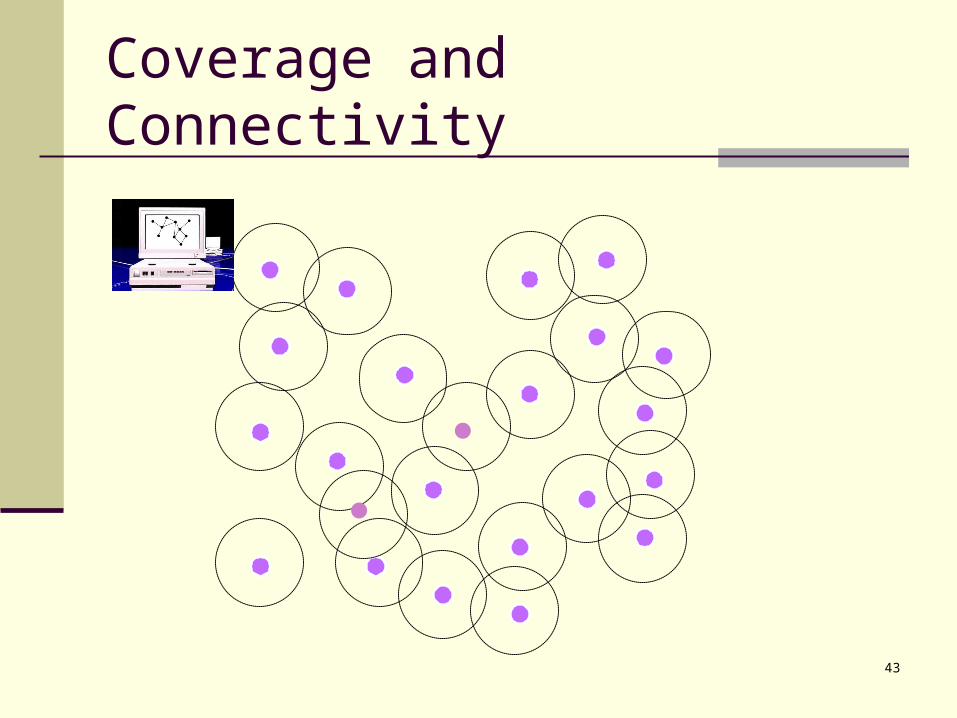
Coverage and Connectivity
44
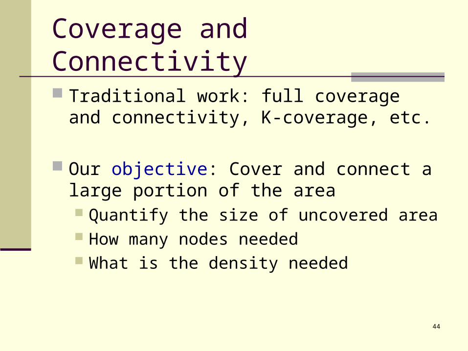
Coverage and Connectivity
Traditional work: full coverage and connectivity, K-coverage, etc.
Our objective: Cover and connect a large portion of the area Quantify the size of uncovered area How many nodes needed What is the density needed

45
Cost and Reliability
Layered structure More expensive nodes with more functionality
Objective: minimize the total cost, including different types (cost) of nodes, while maintaining the desired performance
Reliability important, especially for large scale network nodes damages, out of power, etc.

46
Parking Lot Patrol Problem
Sensors on parking meters Build a wireless sensor network to report
illegal parking Patrolman to find the reported events
Applications: Border patrol Speeding monitoring

47
What Do We Stand?
History: a successful story, an industry of $$$$$$ Current: Policy re-examination underway
Increased unlicensed spectrum allocation Exploration of “underlays”, e.g., UWB Exploration of “overlays”, e.g., opportunistic use of
committed but unused bandwidth Future:
more spectrum better ratio equipment, DSP technologies, longer
battery life Better networks Cool applications

48
![Tao Jiang , Baogui Xin , Baoxian Chang and Liwei Liu · Tao Jiang 1,*, Baogui Xin , Baoxian Chang2 and Liwei Liu3 Abstract. ... Liu et al. [20] studied an M/G/1 retrial G-queue with](https://static.fdocuments.us/doc/165x107/5ed38f653c5d095ede602177/tao-jiang-baogui-xin-baoxian-chang-and-liwei-liu-tao-jiang-1-baogui-xin-.jpg)