
Creviced Window System For Indoor Air Quality Improvement...
14
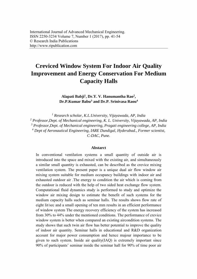
International Journal of Advanced Mechanical Engineering. ISSN 2250-3234 Volume 7, Number 1 (2017), pp. 41-54 © Research India Publications http://www.ripublication.com Creviced Window System For Indoor Air Quality Improvement and Energy Conservation For Medium Capacity Halls Alapati Babji 1 , Dr.Y. V. Hanumantha Rao 2 , Dr.P.Kumar Babu 3 and Dr.P. Srinivasa Raou 4 1 Research scholar, K.L.University, Vijayawada, AP, India 2 Professor,Dept. of Mechanical engineering, K. L. University, Vijayawada, AP, India 3 Professor,Dept. of Mechanical engineering, Pragati engineering college, AP, India 4 Dept of Aeronautical Engineering, IARE Dundigal, Hyderabad., Former scientist, C-DAC, Pune. Abstarct In conventional ventilation systems a small quantity of outside air is introduced into the space and mixed with the existing air, and simultaneously a similar small quantity is exhausted, can be described as the crevice mixing ventilation system. The present paper is a unique dual air flow window air mixing system suitable for medium occupancy buildings with indoor air and exhausted outdoor air .The energy to condition the air which is coming from the outdoor is reduced with the help of two sided heat exchange flow system. Computational fluid dynamics study is performed to study and optimize the window air mixing design to estimate the benefit of such systems for the medium capacity halls such as seminar halls. The results shows flow rate of eight lit/sec and a small opening of ten mm results in an efficient performance of window system The energy recovery efficiency of the system has increased from 30% to 44% under the mentioned conditions. The performance of crevice window system is better when compared an existing aircondition systems. The study shows that such twin air flow has better potential to improve the quality of indoor air quantity. Seminar halls in educational and R&D organization account for major power consumption and hence majour importance to be given to such system. Inside air quality(IAQ) is extremely important since 90% of participants’ seminar inside the seminar hall for 90% of time poor air
Transcript of Creviced Window System For Indoor Air Quality Improvement...
International Journal of Advanced Mechanical Engineering. ISSN 2250-3234 Volume 7, Number 1 (2017), pp. 41-54 © Research India Publications http://www.ripublication.com
Creviced Window System For Indoor Air Quality
Improvement and Energy Conservation For Medium
Capacity Halls
Alapati Babji1, Dr.Y. V. Hanumantha Rao2,
Dr.P.Kumar Babu3 and Dr.P. Srinivasa Raou4
1 Research scholar, K.L.University, Vijayawada, AP, India
2 Professor,Dept. of Mechanical engineering, K. L. University, Vijayawada, AP, India 3 Professor,Dept. of Mechanical engineering, Pragati engineering college, AP, India 4 Dept of Aeronautical Engineering, IARE Dundigal, Hyderabad., Former scientist,
C-DAC, Pune.
Abstarct
In conventional ventilation systems a small quantity of outside air is introduced into the space and mixed with the existing air, and simultaneously a similar small quantity is exhausted, can be described as the crevice mixing ventilation system. The present paper is a unique dual air flow window air mixing system suitable for medium occupancy buildings with indoor air and exhausted outdoor air .The energy to condition the air which is coming from the outdoor is reduced with the help of two sided heat exchange flow system. Computational fluid dynamics study is performed to study and optimize the window air mixing design to estimate the benefit of such systems for the medium capacity halls such as seminar halls. The results shows flow rate of eight lit/sec and a small opening of ten mm results in an efficient performance of window system The energy recovery efficiency of the system has increased from 30% to 44% under the mentioned conditions. The performance of crevice window system is better when compared an existing aircondition systems. The study shows that such twin air flow has better potential to improve the quality of indoor air quantity. Seminar halls in educational and R&D organization account for major power consumption and hence majour importance to be given to such system. Inside air quality(IAQ) is extremely important since 90% of participants’ seminar inside the seminar hall for 90% of time poor air

42 Alapati Babji, et al
quality leads to respiratory illness, allergies, asthma and risk building syndrome. The IAQ has seen regulated by refrigeration and airconditioning, system that proportionality mixes fresh outdoor air with return air supplied to the indoor space. In seminar halls however outdoor air typically enters the hall through doors. According the environment protection agency reports inadequate ventilation can increase the pollution levels.
Keywords: Indoor Air Quality,CFD, LES, Airconditioning
Nomenclature
/p gS Specific density
U Horizontal components of velocity (m/s)
V Vertical component of velocity (m/s)
Ui, Uj Random numbers between 0 and 1
Density (kg/m3)
Time 2( )
18
p p
cp
c d
Relaxation time (s)
t Time step
Kinematic viscosity (m2/s)
Gas mean free path (µm)
1. INTRODUCTION
There are two main challenges in the design of infiltration and ventilation systems. However as the increasingly tight space requirements are demanded for the better performance of a/c system, on the other side decreases space for ventilation and therefore responsible for the possible decrease of indoor air quality. If proper and proportionate air is not brought inside to dilute the emissions the indoor air quality will not be up to the standards. The principal difference between a convectional
Creviced Window System For Indoor Air Quality Improvement and Energy… 43
window and air flow window exists in the convection type in the two layers of glass called air flow cavities. Fundamentally, there are four main modes of operation through windows as supply indoor air curtain, exhaust outdoor air curtain. The air curtains allows air from inside to inside and outside to outside. Air flow is driven by natural, forced and mixed convective currents. The quantity of heat captured and lost by the air flow in both directed curtains depends on the operating mode. Air flow through exhaust window and outdoor curtain helps in removing heat load by convecting away the inside air during cooling season.
The exhaust the air window improves thermal conditions to the comfort levels comparing the convectional window. The seminar hall air temperature mixes with the outside air through the cavities of the exhaust window decreasing the temperature difference between the occupant space and surroundings. This therefore improves the thermal comfort which intern improves air conditioning load during sunny days the outdoor air curtain proved to be more economical comparing to convectional system. Outdoor air is driven in the upward direction in the cavity of outer airflow window keeping the middle class from overheating and hence reduces the conduction to the occupant space
Review of Previous Research
Air supply windows were first developed during 1940’s and later plight of research and execution was conducted during the 1980’s in America (1983) and Erope. The first window airflow patent was filed in Sweden, and patent for “Heat Exchanger Window” in the United States in 1975. Further studies were conducted by Elmahdy and Haddad et.al and Southall, McEvoy et al. (2003) and Baker et al. (2003). The researchers conducted simulations and/or experimental tests for the windows with simulations being used more frequently. For instance, Wright (1986) and Haddad and Elmahdy (1998, 1999) used the VISION computer program to study the windows. A detailed overview of the VISION program development is provided by Haddad and Elmahdy (1998). McEvoy and Southall (2000) and McEvoy et al. (2003) used both a nodal network analysis and computational fluid dynamics (CFD) in their studies. Safer et al. (2004, 2005) used two-dimensional CFD simulations to study a double façade that operates in a way similar to the supply air window. Past research was mostly focused on energy saving aspect of an airflow convective window can be used during the cool and hot seasons. Prominent study also placed on improving or maintaining the thermal comfort in the building. However, To improve IAQ, windows that involve the transfer of air through them in the buildings can marginally improve IAQ and reduce heating/cooling loads. The benefit of ventilation requirements for an indoor space with the supply air window has been significantly studied by Haddad and Elmahdy (1999), McEvoy and South all (2000), and Southall and McEvoy

44 Alapati Babji, et al
(2000). Contemporary design of airflow windows also have several limitations. Several limitations to the implementation of the airflow window also come up from the airflow cavity design in terms of cleaning outdoor air. while airflow through the cavity is driven by buoyancy effect produced due to the solar heat, the use of filters slows down the effectiveness of natural ventilation. Without filtering, though, it may be difficult to keep the window clean. The present research will attempt to deal with the limitations of airflow windows in respect of fresh outdoor air and overcome the flow resistance suitable during filtering. The basic calculation on a building site of a seminar hall in full-scale environmental surroundings provides reliable airflow directions and distributions in and around of a building. The researchers Katayama et al. (1989), Fernandez and Bailey (1992), Dascalaki et al. (1995), and Yuan (1999) have made measurements and recorded, yet, on-site measurements are time consuming and the measured data are normally with low resolution and accuracy hence they cannot be easily generalized. The experiment on the other hand of full-scale environmental situation is not only time consuming but also expensive.
Original Window Design proposed
It is proposed that an airflow window system with the aim of allowing forced air between each glass layer with triple blank entity, two modes of operation, supply and exhaust, as shown in Figure 1. Glazing surfaces are uncoated and the glass is of clear construction. The airflow schematic shows that the outlet and inlet of the airflow are positioned at the same location. Since the exhaust and intake are located at the same height, the width of the window was equally split between inlet and outlet at the top and bottom of the window to avoid short-circuiting tempered fresh air into the indoor air stream.
Due to this positioning of the inlets/outlets, the window system works like a crossflow heat exchanger with solar energy recovery. Exhausted indoor air is used to temper outdoor air, thus reducing heating/cooling demands.
Figure 1
Indoor air is exhausted through the inner airflow cavity of the window system. In this way, the temperature of the interior window surface is close to the seminar hall air

Creviced Window System For Indoor Air Quality Improvement and Energy… 45
temperature and thermal comfort can be improved. Additionally, this window introduces conditioned outdoor air to the interior space through the outer cavity for the improvement of IAQ.
PARAMETRIC STUDY
The authenticated research method was used to conduct a parametric investigation to optimize a dual airflow window system for a choice of different climatic conditions and design parameters. The parameters studied comprises mode of operation either supply type or an exhaust type based on weather conditions either winter or summer, moreover for a sunny or a cloudy day, and finally wind conditions like windy day or a calm one. The airflow crevice provided in the window frame with various crevice openings of 12mm and 15 mm.
The Performance is examined using commercial CFD package for obtaining better heat recovery efficiency. A comparison can be made between the final dual airflow supply creviced window and a single airflow supply window. The analysis is also conducted for a triple glass construction with clear-clear with no surface coatings. The proposed design did not include the impact of the window frame as the present study will not deal with cross-window heat transfer effects.
The computational fluid dynamics is one of the best methods that can be applied to understand the realistic picture of hat transfer in and across the seminar hall which is air conditioned and indoor air quality can be maintained.
Mathematical Modeling
Navier-Stokes equations are the governing equations of Computational Fluid Dynamics. It is based on the conservation law of physical properties of fluid. The principle of conservational law is the change of properties, The mass, energy, and momentum, in an object is decided by the input and output.
Navier-Stokes Equation in general form
To simplify the Navier-Stokes equations, we can rewrite them as the general form.
q
xU
xt i
i
i
(1)
Where
TU j ,,1

46 Alapati Babji, et al
The change of mass in the object is as follows
outin mmdt
dM
(2)
If 0 outin mm
0dt
dM
(3)
Compressible fluid flow we can write the continuity equation and momentum equation as follows.
Continuity Equation
0
i
i
x
U
(4)
Momentum Equation
j
i
j
ji
j
i
jg
x
U
x
P
x
UU
t
U
2
2
(5)
Finite Volume Method approach
Integrating the general form of Navier-Stokes equation over a control volume and apply Gauss Theory
S
i
V i
dSndVx (6)
We can get the integral form of Navier-Stoke equation
VS
i
i
i
V
dVqdSnx
UdVt
(7)

Creviced Window System For Indoor Air Quality Improvement and Energy… 47
To approximate the the volume integral, we can multiply the volume and the value at the center of the control volume. To approximate the mass and momentum of control volume P, we have
VdVm p
Vi
,
VudVumu PP
V
ii
i
(8)
RESULTS AND DISCUSSION
The best possible airflow window configuration has to to depend on the mode of operation and the weather conditions. The supply mode may be mainly effective during winter months, whereas the exhaust mode may be the most effective during summer. The working modes could make use of buoyancy effects to drive airflow in the window cavity thus the energy consumption of the fan possibly will be minimized.
The exit temperature for the supply and exhaust modes are kept in the limits of recirculation temperature. Results are presented for summer and winter conditions with a sunny or cloudy sky. The most desirable mode of operation would provide the highest exit temperature to the indoors during the winter and the lowest exit temperature to the indoors during the summer. For a flow rate of 8-10 L/s, the supply mode was slightly better during the winter and the exhaust mode slightly better during the summer. Since this difference is a mere 1°C or less, mode of operation is not important when fans were used to drive the flow. For the range of flow rates studied, the ratio of the largest Grashof number to the square of the smallest Reynolds number was 3.8x10⁻³. Since this value is much less than one, forced convection effects are dominant in the fan driven airflow setup. As a result the following analysis will be limited to a study of the supply air window configuration
Figure 2
48 Alapati Babji, et al
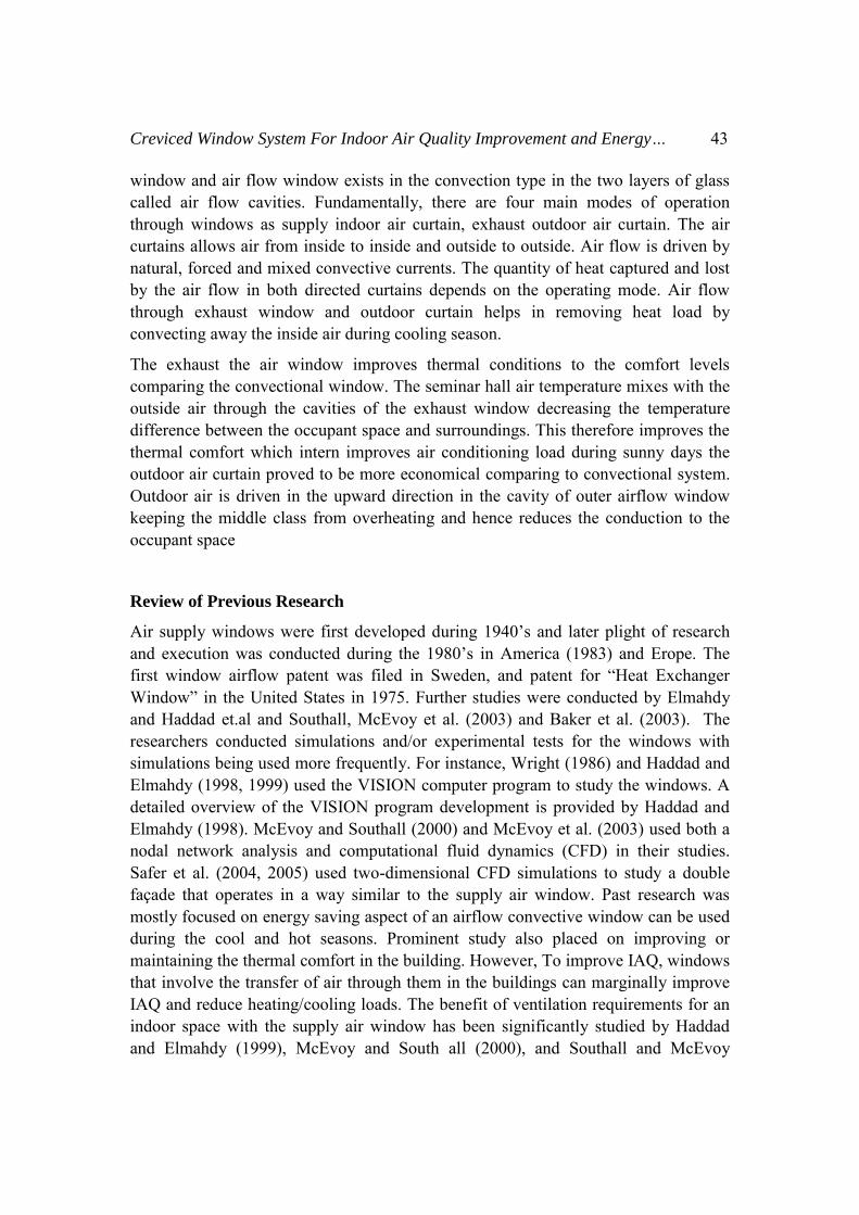
Figure 3
Figure 4
In this section, the subgrid-scale models of LES are used to study both indoor and outdoor airflows. The examples of indoor airflows are natural, forced, and mixed convection, which are common situations inside a building. The results are then compared with experimental data to evaluate the model performance
Creviced Window System For Indoor Air Quality Improvement and Energy… 49
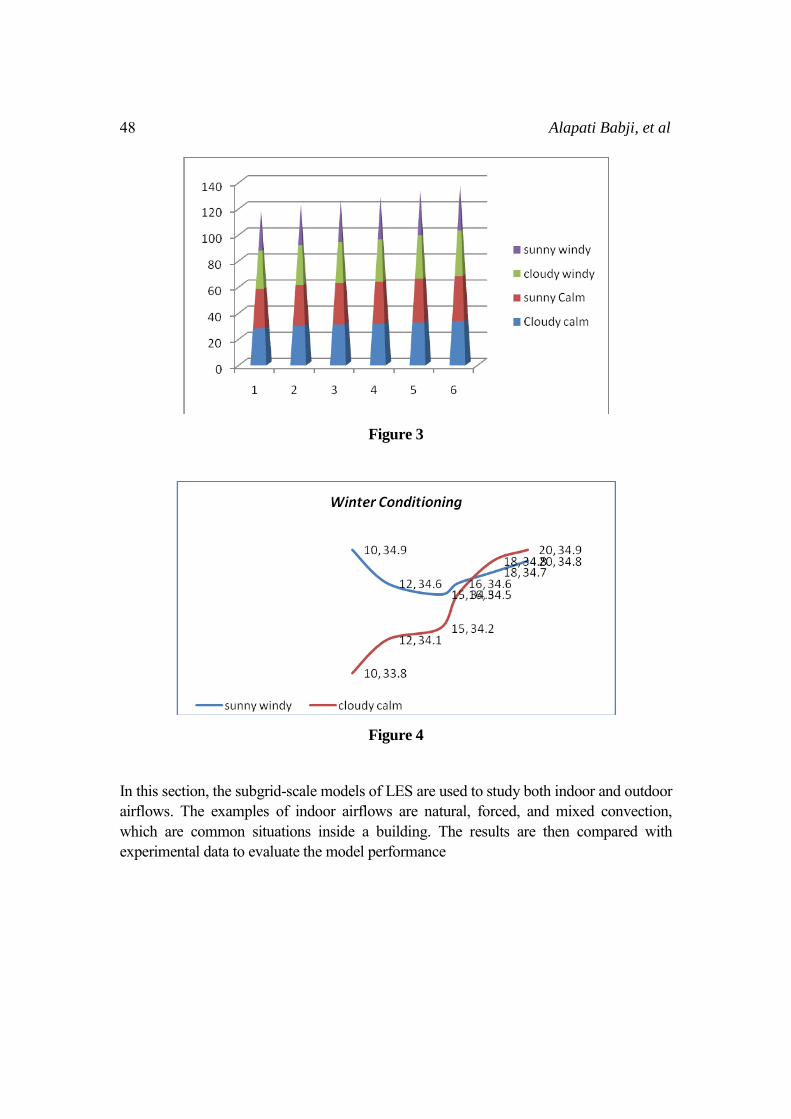
Figure 5
Figure 6
Natural Convection in a Seminar hall
To study indoor airflow driven by buoyancy forces, the airflow circulated within a cold and a warm wall is investigated. Although this cavity type is not a real indoor condition, the airflow characteristics are very similar to those inside a seminar hall. Therefore, this case can be regarded as an indoor airflow driven by buoyancy forces. Detailed air velocity, temperature, turbulence energy, and heat transfer were measured by Cheesewright et al. (1986).
50 Alapati Babji, et al
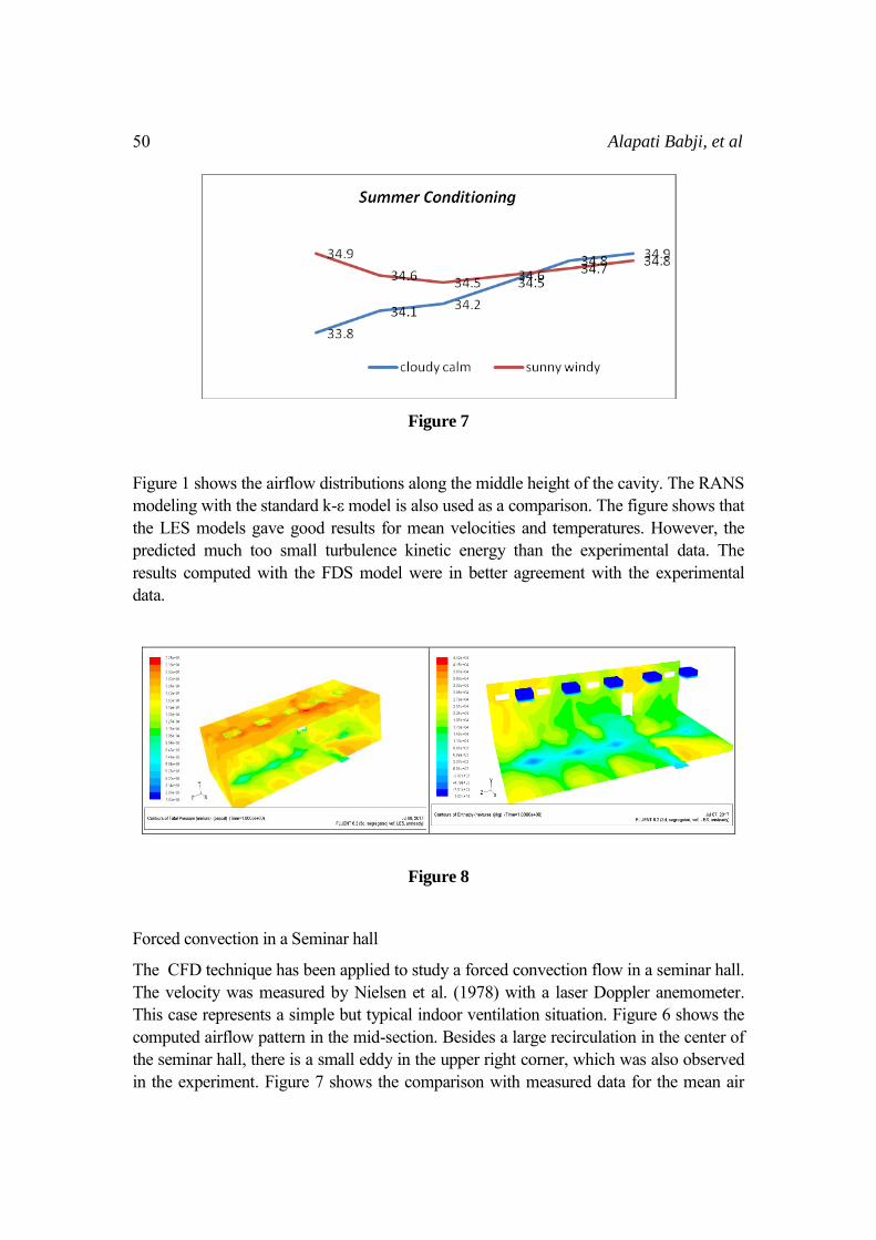
Figure 7
Figure 1 shows the airflow distributions along the middle height of the cavity. The RANS modeling with the standard k-ε model is also used as a comparison. The figure shows that the LES models gave good results for mean velocities and temperatures. However, the predicted much too small turbulence kinetic energy than the experimental data. The results computed with the FDS model were in better agreement with the experimental data.
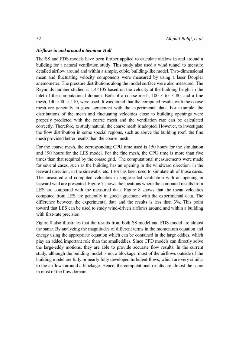
Figure 8
Forced convection in a Seminar hall
The CFD technique has been applied to study a forced convection flow in a seminar hall. The velocity was measured by Nielsen et al. (1978) with a laser Doppler anemometer. This case represents a simple but typical indoor ventilation situation. Figure 6 shows the computed airflow pattern in the mid-section. Besides a large recirculation in the center of the seminar hall, there is a small eddy in the upper right corner, which was also observed in the experiment. Figure 7 shows the comparison with measured data for the mean air

Creviced Window System For Indoor Air Quality Improvement and Energy… 51
velocity, represented, and the fluctuating air velocity, represented by a different color. This suggests that for indoor airflow cases, in which walls normally have significant effects and both turbulent and laminar flows exist, the creviced model may be more appropriate.
Figure 9
Mixed Convection in a Seminar hall
The mixed convection considered is the airflow in a seminar hall with Crevice ventilation. thorough experimental measurements on the distributions of air velocity, air temperature, and contaminant concentration by using a tracer-gas. The experimental results are corroborated with CFD model. The conditioned air is supplied through a diffuser in the lower part of a seminar hall and warm air was exhausted at the ceiling level.
The seminar hall has two hundred occupants, two PCs, overhead lighting, and furniture. Figure 6 shows the mean airflow pattern in the mid-section of the seminar hall obtained. Because of the buoyancy effect, the cold air from the diffuser moved rapidly downwards along the floor. The mean airflow pattern showed a large but weak recirculation in the lower part of the seminar hall. In the upper part of the seminar hall, there were some recirculations caused by the thermal plumes from heated objects, such as PCs, occupants, and overhead lights. The computed airflow pattern was similar to that observed in the measurement. Figure 5 compares the computed mean air velocity, temperature, and SF6 concentration with the experimental data in the center of the seminar hall. A model may work better than the others in one location but poorer in another The Reynolds numbers are computed based on the inlet height and inlet velocity and Rayleigh numbers are computed based on the temperature difference between the cold and the warm walls, the height of the walls and the distance between the two walls. The computing time required is 20 CPU hours.
52 Alapati Babji, et al
Airflows in and around a Seminar Hall
The SS and FDS models have been further applied to calculate airflow in and around a building for a natural ventilation study. This study also used a wind tunnel to measure detailed airflow around and within a simple, cubic, building-like model. Two-dimensional mean and fluctuating velocity components were measured by using a laser Doppler anemometer. The pressure distributions along the model surface were also measured. The Reynolds number studied is 1.4×10⁵ based on the velocity at the building height in the inlet of the computational domain. Both of a coarse mesh, 100 × 65 × 80, and a fine mesh, 140 × 80 × 110, were used. It was found that the computed results with the coarse mesh are generally in good agreement with the experimental data. For example, the distributions of the mean and fluctuating velocities close to building openings were properly predicted with the coarse mesh and the ventilation rate can be calculated correctly. Therefore, to study natural, the coarse mesh is adopted. However, to investigate the flow distribution in some special regions, such as above the building roof, the fine mesh provided better results than the coarse mesh.
For the coarse mesh, the corresponding CPU time used is 150 hours for the simulation and 190 hours for the LES model. For the fine mesh, the CPU time is more than five times than that required by the coarse grid. The computational measurements were made for several cases, such as the building has an opening in the windward direction, in the leeward direction, in the sidewalls, etc. LES has been used to simulate all of those cases. The measured and computed velocities in single-sided ventilation with an opening in leeward wall are presented. Figure 7 shows the locations where the computed results from LES are compared with the measured data. Figure 8 shows that the mean velocities computed from LES are generally in good agreement with the experimental data. The difference between the experimental data and the results is less than 3%. This point toward that LES can be used to study wind-driven airflows around and within a building with first-rate precision
Figure 8 also illustrates that the results from both SS model and FDS model are almost the same. By analyzing the magnitudes of different terms in the momentum equation and energy using the appropriate equation which can be contained in the large eddies, which play an added important role than the smalleddies. Since CFD models can directly solve the large-eddy motions, they are able to provide accurate flow results. In the current study, although the building model is not a blockage, most of the airflows outside of the building model are fully or nearly fully developed turbulent flows, which are very similar to the airflows around a blockage. Hence, the computational results are almost the same in most of the flow domain.

Creviced Window System For Indoor Air Quality Improvement and Energy… 53
CONCLUSIONS
The results show that the expulsion coefficient for a window crevice cannot be regarded as unvarying modification actually it varies considerably with the size of the crevice of the window and temperature difference across the window. If it is treated as constant the conditioning status and performance can lead to errors and hence the prediction of air flow capacity can go wrong. The results have been optimistic and will continue to improve the IAQ. The obtained data could be used to develop better understanding and hence includes a new parameter known as expulsion coefficient in natural ventilation design of medium sized seminar halls. To estimate and predict the thermal comfort in the occupied space is also of greater importance because of air flow from window openings cannot make the conditioning system to rapidly modify the seminar hall air flow situation. The LES turbulence is applied to study natural ventilation which is superior to break up the indoor airflow and outdoor airflow simulations. The separation facilitates to ensure the computational domain which is sufficiently large to precisely simulate the indoor airflow with sufficiently fine grid to obtain detailed flow information.
REFERENCES
[1.] ASHRAE. 2003a. ASHRAE Standard 62.2-2003 Ventilation for Acceptable
Indoor Air Quality, Atlanta: American Society of Heating, Ventilating and Air Conditioning Engineers, Inc.
[2.] McEvoy, M.E., R.G. Southall, and P.H. Baker. 2003. Test cell evaluation of supply air windows to characterize their optimum performance and its verification by the se of modeling techniques. Energy and Buildings. 35: 1009-1020.
[3.] Baker, P.H., M.E. McEvoy and R. Southall. 2003. Improving air quality in homes with supply air windows. BRE Information Paper.
[4.] Barakat, S.A. 1987. Thermal performance of a supply-air window. Proceedings of the 12th Annual Passive Solar Conference 12: 152-158.
[5.] Brandle, K. and R.F. Boehm. 1982. Airflow windows: performance and applications. ASHRAE/DOE Conference, Proceedings of Thermal
Performance of the Exterior Envelopes of Buildings II. Las Vegas. [6.] Southall, R.G. and M. McEvoy. 2000. Results from a validated CFD
simulation of a supply air ‘ventilated’ window. Proceedings of Roomvent
2000, Stockholm, Sweden. [7.] Etzion, Y. and E. Erell. 2003. Controlling the transmission of radiant energy
through windows: a novel ventilated reversible glazing system. Building and
Environment. 35(5): 433-444. [8.] Erell E., Y. Etzion, N. Carlstrom, M. Sandberg, J. Molina, I. Maestre, E.
Maldonado, V. Leal and O. Gutschker. 2004. ‘SOLVENT’: Development of a

54 Alapati Babji, et al
reversible solar-screen glazing system. Energy and Buildings. 36(5): 467-480. [9.] Haddad, K.H. and A.H. Elmahdy. 1998. Comparison of the monthly thermal
performance of a conventional window and a supply-air window. ASHRAE
Transactions. 104(1B):1261- 1270. [10.] McEvoy, M. and R.G. Southall. 2000. Validation of a computational fluid
dynamics simulation of a supply air ‘ventilated’ window. CISBE Conference. Dublin, Ireland.
[11.] Haddad, K.H. and A.H. Elmahdy. 1999. Comparison of the thermal performance of an exhaust air window and a supply-air window. ASHRAE
Transactions. 105(2):918-926. [12.] Inoue, T., Y. Matsuo, and T. Ibamoto. 1985. Study on the thermal
performance of ventilation window. Proceedings of International Symposium
on Thermal Application of Solar Energy. [13.] Leal, V., E. Maldonado, E. Erell, and Y. Etzion. 2003. Modeling a reversible
ventilated window for simulation within ESP-R – the SOLVENT case. Proceedings of Building Simulation 2003
[14.] Leal, V., M. Sandberg, E. Maldonado, and E. Erell. 2004. An analytical model for the airflow in a ventilated window with known surface temperatures. Proceedings of Roomvent 2004, Coimbra, Portugal.
[15.] Ferguson, J.E. and J.L. Wright. 1984. VISION: A computer program to evaluate the thermal performance of super windows. Report No. Passive-10, Ottawa: National Research Council Canada.
[16.] Müller, H. 1983. Exhaust-air ventilated windows in office buildings. Proceedings of the 18th Intersociety Energy Conversion Conference Vol. 5, pp. 2015-2018. NREL. 1995. Typical meteorological year data.
[17.] Safer, N., M. Woloszyn, J.J. Roux, G. Rusaouen, and F. Kuznik. 2005. Modeling of the double skin facades for building energy simulations: radiative and convective heat transfer.
[18.] Proceedings of Building Simulation 2005, pp. 1067-1074, Montreal, Canada. Sherman, M.H. and N. Matson. 1997. Residential ventilation and energy characteristics. LBNL 39036.