Crescendo Tool Support: User Manualcrescendotool.org/documents/Crescendo-2.0.0-UserManual.pdf ·...
78
Crescendo Technical Report Series No. TR-001 November 2013 Crescendo Tool Support: User Manual Version 2.0.0 by Peter Gorm Larsen, Kenneth Lausdahl, Joey Coleman and Sune Wolff Aarhus University, Department of Engineering Finlandsgade 22, DK-8200 Aarhus N, Denmark Christian Kleijn and Frank Groen Controllab Products B.V. Hengelosestraat 500, 7521 AN Enschede, The Netherlands Crescendo – Co-Simulation for Embedded Control Systems
Transcript of Crescendo Tool Support: User Manualcrescendotool.org/documents/Crescendo-2.0.0-UserManual.pdf ·...

Crescendo Technical Report SeriesNo. TR-001
November 2013
Crescendo Tool Support: User ManualVersion 2.0.0
by
Peter Gorm Larsen, Kenneth Lausdahl, Joey Coleman and Sune WolffAarhus University, Department of EngineeringFinlandsgade 22, DK-8200 Aarhus N, Denmark
Christian Kleijn and Frank GroenControllab Products B.V.
Hengelosestraat 500, 7521 AN Enschede, The Netherlands
Crescendo – Co-Simulation for Embedded Control Systems
Crescendo Tool Support: User Manual
Document historyMonth Year Version Version of Crescendo.exeDecember 2012 1 1.1.8 (then called DESTECS)November 2013 2 2.0.0January 2014 3 2.0.0 (review by M. Verhoef)
ii
Contents
1 Introduction 11.1 What is the Crescendo Tool? . . . . . . . . . . . . . . . . . . . . . . . . . . . . . 11.2 What was the DESTECS Project? . . . . . . . . . . . . . . . . . . . . . . . . . . 11.3 What is the Vienna Development Method? . . . . . . . . . . . . . . . . . . . . . . 11.4 What are Bond Graphs? . . . . . . . . . . . . . . . . . . . . . . . . . . . . . . . . 21.5 Related Tools . . . . . . . . . . . . . . . . . . . . . . . . . . . . . . . . . . . . . 3
1.5.1 Overture . . . . . . . . . . . . . . . . . . . . . . . . . . . . . . . . . . . 31.5.2 Crescendo . . . . . . . . . . . . . . . . . . . . . . . . . . . . . . . . . . . 31.5.3 Symphony . . . . . . . . . . . . . . . . . . . . . . . . . . . . . . . . . . 3
1.6 Structure of this User Manual . . . . . . . . . . . . . . . . . . . . . . . . . . . . . 4
2 Basic Crescendo Concepts 52.1 Models . . . . . . . . . . . . . . . . . . . . . . . . . . . . . . . . . . . . . . . . 52.2 Simulation . . . . . . . . . . . . . . . . . . . . . . . . . . . . . . . . . . . . . . . 52.3 Co-Simulation . . . . . . . . . . . . . . . . . . . . . . . . . . . . . . . . . . . . . 62.4 Contract . . . . . . . . . . . . . . . . . . . . . . . . . . . . . . . . . . . . . . . . 6
3 Getting Hold of the Software 73.1 Requirements . . . . . . . . . . . . . . . . . . . . . . . . . . . . . . . . . . . . . 73.2 Installation . . . . . . . . . . . . . . . . . . . . . . . . . . . . . . . . . . . . . . 7
3.2.1 Combined Installer . . . . . . . . . . . . . . . . . . . . . . . . . . . . . . 73.2.2 Licence . . . . . . . . . . . . . . . . . . . . . . . . . . . . . . . . . . . . 83.2.3 Manuals . . . . . . . . . . . . . . . . . . . . . . . . . . . . . . . . . . . . 8
3.3 20-sim Standalone . . . . . . . . . . . . . . . . . . . . . . . . . . . . . . . . . . 8
4 Quick Start with Crescendo 114.1 Opening Crescendo . . . . . . . . . . . . . . . . . . . . . . . . . . . . . . . . . . 114.2 Opening a Project . . . . . . . . . . . . . . . . . . . . . . . . . . . . . . . . . . . 124.3 Running a Project . . . . . . . . . . . . . . . . . . . . . . . . . . . . . . . . . . . 12
5 Editors and Management of Projects 175.1 The Crescendo Workbench . . . . . . . . . . . . . . . . . . . . . . . . . . . . . . 17
5.1.1 Explorer View . . . . . . . . . . . . . . . . . . . . . . . . . . . . . . . . 18
iii

Crescendo Tool Support: User Manual
5.1.2 Editor View . . . . . . . . . . . . . . . . . . . . . . . . . . . . . . . . . . 185.1.3 Outline View . . . . . . . . . . . . . . . . . . . . . . . . . . . . . . . . . 195.1.4 Simulation Engine View . . . . . . . . . . . . . . . . . . . . . . . . . . . 195.1.5 Console View . . . . . . . . . . . . . . . . . . . . . . . . . . . . . . . . . 20
5.2 Handling Projects . . . . . . . . . . . . . . . . . . . . . . . . . . . . . . . . . . . 215.2.1 Creating new Projects . . . . . . . . . . . . . . . . . . . . . . . . . . . . 215.2.2 Importing Projects . . . . . . . . . . . . . . . . . . . . . . . . . . . . . . 215.2.3 Exporting Projects . . . . . . . . . . . . . . . . . . . . . . . . . . . . . . 23
5.3 Managing Contracts . . . . . . . . . . . . . . . . . . . . . . . . . . . . . . . . . . 245.3.1 Creating a new Contract File . . . . . . . . . . . . . . . . . . . . . . . . . 245.3.2 Contents of a Contract . . . . . . . . . . . . . . . . . . . . . . . . . . . . 255.3.3 Error Detection in the Contract/Link File . . . . . . . . . . . . . . . . . . 275.3.4 Managing the Link Files . . . . . . . . . . . . . . . . . . . . . . . . . . . 285.3.5 Contract Overview . . . . . . . . . . . . . . . . . . . . . . . . . . . . . . 30
6 Co-Simulation 316.1 Debug Configuration . . . . . . . . . . . . . . . . . . . . . . . . . . . . . . . . . 31
6.1.1 Creating a New Debug Configuration . . . . . . . . . . . . . . . . . . . . 316.1.2 Main Tab . . . . . . . . . . . . . . . . . . . . . . . . . . . . . . . . . . . 316.1.3 Shared Design Parameters Tab . . . . . . . . . . . . . . . . . . . . . . . . 336.1.4 DE Simulator Tab . . . . . . . . . . . . . . . . . . . . . . . . . . . . . . 336.1.5 CT Simulator Tab . . . . . . . . . . . . . . . . . . . . . . . . . . . . . . . 34
6.2 Post-Processing Tab . . . . . . . . . . . . . . . . . . . . . . . . . . . . . . . . . . 356.2.1 Advanced Tab . . . . . . . . . . . . . . . . . . . . . . . . . . . . . . . . 356.2.2 Common Tab . . . . . . . . . . . . . . . . . . . . . . . . . . . . . . . . . 35
6.3 Scenarios . . . . . . . . . . . . . . . . . . . . . . . . . . . . . . . . . . . . . . . 366.3.1 Creating a New Scenario File . . . . . . . . . . . . . . . . . . . . . . . . 376.3.2 CSL Syntax . . . . . . . . . . . . . . . . . . . . . . . . . . . . . . . . . . 376.3.3 CSL Examples . . . . . . . . . . . . . . . . . . . . . . . . . . . . . . . . 38
6.4 Logfiles . . . . . . . . . . . . . . . . . . . . . . . . . . . . . . . . . . . . . . . . 396.4.1 DE Variables . . . . . . . . . . . . . . . . . . . . . . . . . . . . . . . . . 40
7 Design Space Exploration 437.1 ACA Workflow . . . . . . . . . . . . . . . . . . . . . . . . . . . . . . . . . . . . 437.2 Using the ACA Features . . . . . . . . . . . . . . . . . . . . . . . . . . . . . . . 44
7.2.1 The Main Tab . . . . . . . . . . . . . . . . . . . . . . . . . . . . . . . . . 447.2.2 The Architecture Tab - Deployment Architectures . . . . . . . . . . . . . . 457.2.3 Shared Design Parameters Tab . . . . . . . . . . . . . . . . . . . . . . . . 457.2.4 Scenario Tab . . . . . . . . . . . . . . . . . . . . . . . . . . . . . . . . . 477.2.5 CT Settings Tab . . . . . . . . . . . . . . . . . . . . . . . . . . . . . . . . 487.2.6 Common Tab . . . . . . . . . . . . . . . . . . . . . . . . . . . . . . . . . 48
7.3 Repeating a Single Launch Part of an ACA . . . . . . . . . . . . . . . . . . . . . 48
iv

CONTENTS
7.4 Folder Launch Configuration . . . . . . . . . . . . . . . . . . . . . . . . . . . . . 497.5 Control Library . . . . . . . . . . . . . . . . . . . . . . . . . . . . . . . . . . . . 49
7.5.1 Accessing the Control Library . . . . . . . . . . . . . . . . . . . . . . . . 507.5.2 Using the Control Library . . . . . . . . . . . . . . . . . . . . . . . . . . 517.5.3 Advanced Use . . . . . . . . . . . . . . . . . . . . . . . . . . . . . . . . 527.5.4 Constructors . . . . . . . . . . . . . . . . . . . . . . . . . . . . . . . . . 52
7.6 DE Architecture . . . . . . . . . . . . . . . . . . . . . . . . . . . . . . . . . . . . 547.7 Events . . . . . . . . . . . . . . . . . . . . . . . . . . . . . . . . . . . . . . . . . 55
7.7.1 Simulation setup . . . . . . . . . . . . . . . . . . . . . . . . . . . . . . . 557.7.2 Events in CT . . . . . . . . . . . . . . . . . . . . . . . . . . . . . . . . . 567.7.3 Events in DE . . . . . . . . . . . . . . . . . . . . . . . . . . . . . . . . . 56
8 Post-Analysis 598.1 Octave . . . . . . . . . . . . . . . . . . . . . . . . . . . . . . . . . . . . . . . . . 59
8.1.1 Octave use in Crescendo . . . . . . . . . . . . . . . . . . . . . . . . . . . 598.1.2 Show Plot Automatically when Script is Run . . . . . . . . . . . . . . . . 598.1.3 Invoking Octave from Crescendo . . . . . . . . . . . . . . . . . . . . . . 608.1.4 Setting Octave path . . . . . . . . . . . . . . . . . . . . . . . . . . . . . . 60
8.2 Folder Launch Configuration . . . . . . . . . . . . . . . . . . . . . . . . . . . . . 60
A Glossary 65
v

Crescendo Tool Support: User Manual
vi

ABSTRACT
This document is the user manual for the Crescendo Integrated Development Environment (IDE)version 2.0.0, enabling collaborative analysis of models written in the Discrete Event (DE) formal-ism VDM and the Continuous Time (CT) formalism bond graphs. The specific dialect of VDMused is called VDM Real Time (VDM-RT) and it is supported by the Overture tool whereas thebond graph formalism is supported by the tool 20-sim. Both Crescendo and Overture are built ontop of the Eclipse platform.

Chapter 1
Introduction
1.1 What is the Crescendo Tool?The Crescendo tool was originally called the DESTECS tool since it was produced in the Euro-pean Seventh Framework research project called DESTECS (see Section 1.2 below). It supports amethod of collaborative modelling and simulation called co-simulation.
1.2 What was the DESTECS Project?The DESTECS (Design Support and Tooling for Embedded Control Software)1 project was per-formed by a consortium of research groups and companies working on the challenge of develop-ing fault-tolerant embedded systems [BLV+10]. The consortium focussed on developing designmethods and tools that bridge the gap between the disciplines involved in designing an embeddedsystem: systems, control, mechanical and software engineering, for example. DESTECS aimedto develop methods and tools that combine Continuous-Time (CT) models with Discrete-Event(DE) controller models through co-simulation to allow multi-disciplinary modelling, includingmodelling of faults and fault tolerance mechanisms. The analysis of these effects at every stagein a design process will help to build more dependable real-time embedded systems. The DEmodelling is carried out using the Vienna Development Method and its support tool Overture (seeSection 1.3 below). The CT modelling is carried out using bond graphs and its support tool 20-sim(see Section 1.4 below).
1.3 What is the Vienna Development Method?The Vienna Development Method (VDM) is one of the oldest established model-oriented formalmethods for the development of computer-based systems and software [BJ78, Jon90, FLV08]. Itconsists of a group of mathematically well-founded languages for expressing and analysing system
1See www.destecs.org.
1
Crescendo Tool Support: User Manual
models during early design stages, with the aim to reduce developments risks before expensive im-plementation commitments are made. VDM has a strong record of industrial applications, in manycases it has been used by practitioners who were not specialists in the underlying formalism orlogic [LH96,CCFJ99,KN09]. Experience with the method suggests that the effort spent on formalmodelling and analysis can be recovered easily in reduced rework costs arising from preventeddesign errors.
VDM models are expressed in a specification language (VDM-SL) which supports the descrip-tion of data and functionality [ISO96, FL98, FL09]. Data is defined by means of abstract datatypes built using constructors that define structured data and collections such as sets, sequencesand mappings from basic values such as Booleans, reals, characters and natural numbers. Thesetypes are very abstract, allowing you to add any relevant constraints using data type invariants.Functionality is defined in terms of operations over these data types. Operations can be definedimplicitly by preconditions and postconditions that characterize their behavior, or explicitly bymeans of specific algorithms. An extension of VDM-SL, called VDM++, supports object-orientedstructuring of models and also permits direct modelling of concurrency [FLM+05]. A furtherextension to VDM++, called VDM Real Time (VDM-RT2), which includes support for explicitcomputing and communication architectures for executing specific deployments of discrete timemodels [MBD+00, VLH06]. All three VDM dialects are supported by Overture.
1.4 What are Bond Graphs?
Bond graphs are directed graphs in which the vertices are submodels and the edges, called bonds,denote the ideal (or idealised) exchange of energy between those submodels. Entry points ofsubmodels are called ports. The exchange of energy through a port (p) is always described bytwo implicit variables, effort (p.e) and flow (p.f ). The product of these variables is the amount ofenergy that passes through the port. The meaning of these two variables depends on the physicaldomain (examples include voltage and current, and force and velocity), which makes the methodideal for multi-domain modelling.
The 20-sim tool supports the creation and simulation of models that can be represented in avariety of forms, including basic bond graphs; collections of differential equations describing thebehaviour of nodes; and iconic diagram. Although the 20-sim tool is commercial, all the modellibraries are open source. The package supports mixed-mode integration techniques to allow themodelling and simulation of computer controlled physical systems that contain Continuous-Timeas well as Discrete-Event elements. The level of complexity of many modern controllers meansthat discrete-event elements are better modelled using a rich formalism such as VDM. The 20-simpackage supports the connection of external software both for model construction and simula-tion (Discrete-Event, Continuous-Time or hybrid), and this connection is exploited in providingsupport for co-simulation.
2Originally called VDM In a Constrained Environment (VICE).
2

CHAPTER 1. INTRODUCTION
1.5 Related Tools
The Crescendo tool is one of a family of tools with common shared code.
1.5.1 Overture
The Overture tool (www.overturetool.org) represents the opening of these tools. This toolis build on top of the Eclipse platform and it support all the VDM dialects: VDM-SL, VDM++and VDM Real-Time (VDM-RT). Many different features are included but the emphasis is onvalidation of VDM models by interpretation of executable subsets. This also includes support forDE notation VDM-RT used inside the Crescendo tool. Users who are only interested in DiscreteEvent (DE) modelling using one or more of the VDM dialects should use this Overture tool.
1.5.2 Crescendo
The Crescendo tool (www.crescendotool.org) is a gradual increase of the Overture tool inthe sense that it has all the support present inside Overture and in addition it supports collaborativemodelling and simulation with a combination of the DE notation VDM-RT and the ContinuousTime (CT) simulation by the 20-sim tool3. This is particular useful for those who are interested inmodelling and validation of embedded control systems including modelling of the physical plantsto be controlled. Users who are interested in both DE and CT modelling in a collaborative fashionshould use this.
1.5.3 Symphony
The Symphony tool (www.symphonytool.org) is an extended musical composition carriedout by a large band (i.e. a System of Systems). This tool is developed in the COMPASS project4
and it supports the COMPASS Modelling Language (CML). Symphony is also an extension of theOverture tool in the sense that it has all the support present inside Overture. CML is a combinationof VDM and CSP/Circus. This tool provides validation using execution of an executable subsetand test automation using the RT Tester tool as well as formal verification using model checking(partially supported by the FORMULA model checker) and theorem proving (partially supportedby the Isabelle theorem prover). Users who are interested in modelling and analysis of Systems ofSystems should use this.
3This tool was originally developed in the DESTECS (Design Support and Tooling for Embedded Control Software)project. This was partially supported by EU as project number 248134 under the embedded system design area.
4This is an acronym for “Comprehensive Modelling for Advanced Systems of Systems” project number 287829 underthe EU FP7 programme.
3

Crescendo Tool Support: User Manual
1.6 Structure of this User ManualThis user manual explains how to use the Crescendo IDE for developing collaborating models(co-models) and analysing them. In essence it is structured in 2 parts: The first part providesthe basics for getting started using the Crescendo tool and the second part acts as a referencemanual for the Crescendo tool. The first part contains Chapter 2 introducing the basic Crescendoconcepts5; Chapter 3 explans how to get hold of the software; and finally Chapter 4 explains howto quickly get started using the Crescendo tool with existing models that can be imported directly.Afterwards the second part also contains four chapters explaining the main possibilities in theCrescendo tool. Chapter 5 explains the different views in the Crescendo tool, its editors and itsway of handling projects. Chapter 6 explains the co-simulation possibilities. This is followed byChapter 7 which provides information about how co-simulation can be extended with exploringthe candidate design space. Finally this part is completed in Chapter 8 explaining the post-analysispossibilities in particular relevant to exploratory situations.
5Appendix A provides a complete list of the Crescendo common concepts.
4

Chapter 2
Basic Crescendo Concepts
The Crescendo tool allows you to define co-models and to perform a co-simulation. To get abasic understanding of the tool, we first need to define some concepts. We will use use a populardescription of these concepts that might not be completely correct but will, hopefully, enhance theunderstanding of users who are new to Crescendo.
2.1 Models
It starts with models. Models are a more or less abstract representation of a system or componentof interest. In Crescendo we use Continuous-Time models (CT models) and Discrete-Event models(DE models). CT models are models that describe real physical systems. These models describethe behaviour of physical systems at any desired time. DE models typically describe computersystems that run at predetermined time steps. Between these time steps nothing happens.
2.2 Simulation
Continuous-Time models can be created and simulated in 20-sim. This tool will simulate CTmodels with as many small time steps as required to get accurate results. Sometimes the accuracyis violated. The tool will then step back and use smaller time steps until the required accuracyis met. This is called a Continuous-Time simulation. A Continuous-Time simulation is thereforealways characterized by the accuracy of the simulation and the time steps taken. Discrete-Eventmodels can be created and simulated in Overture/VDM. This tool will simulate Discrete-Eventmodels with predetermined discrete time steps. This is called a Discrete-Event simulation. Thereare no accuracy issues involved and therefore no backstepping is required.
The properties of a model that affects its behaviour, but which remain constant during a simula-tion are called parameters. Examples of parameters are for example the height of a watertank orthe mass of a car. A variable is a property of a model that may change during a given simulation,for example the varying waterlevel of a watertank or the varying speed of a car.
5
Crescendo Tool Support: User Manual
2.3 Co-SimulationA co-simulation is a combined simulation of a Continuous-Time model and a Discrete-Event modelin separate tools. The Crescendo tool allows you to run Discrete-Event models in VDM andContinuous-Time models in 20-sim and exchange information between VDM and 20-sim duringrun time. Because the notion of a model in a co-simulation may lead to misinterpretations, we willuse the following definitions:
constituent model: the CT submodel or the DE submodel of a co-simulation.
co-model: a model comprising two constituent models (a DE submodel and a CT submodel).
2.4 ContractThe description of the communication between the constituent models of a co-model is called thecontract. A contract typically describes the variables that are shared between the Continuous-Timemodel and the Discrete-Event model. An example of a shared variable is the waterlevel thatis calculated in the Continuous-Time model and sent to the Discrete-Event model where it is usedto calculate the response of a water level controller.
In most cases a Continuous-Time model and a Discrete-Event model will use similar param-eters. For the watertank example such a parameter may be the maximum water level. In theContinuous-Time model this parameter indicates the height at which a sensor is placed and in theDiscrete-Event model this parameter may indicate a property of the water level controller. To pre-vent different values to be used in the Continuous-Time model and Discrete-Event model, we mayshare this parameter in the contract. This is called a shared design parameter.
6

Chapter 3
Getting Hold of the Software
3.1 RequirementsThe Crescendo tool suite can be downloaded as a single installation package from the Crescendowebsite. The package contains a full installation for Overture/VDM, 20-sim and the Crescendotools. Overture/VDM and the Crescendo tools are open source tools and will run on any computerequipped with a Java virtual machine. However, 20-sim is a commerical tool that will run as aviewer on any Windows computer. If you want to build your own models in 20-sim and storethem, you will need a license (see Section 3.2). In order to install to package of the Crescendopackage you need to have:
• Windows platform (XP / Vista / 7 / 8)
• At least 256 MB memory
• At least 200 MB free disk space
• An x86 compatible CPU
3.2 Installation
3.2.1 Combined InstallerFirst-time users are advised to use the combined installer that will install the Crescendo tool andthat will also include the Overture/VDM features and the 20-sim tool on your computer. You candownload the installer from the Crescendo website:
http://www.crescendotool.org
During installation the main installer will pause. A second installer will then guide you throughthe installation of 20-sim. Once 20-sim is installed, the Crescendo installer will continue. Boththe Overture/VDM tool as well as the Crescendo tool are released as open source under the GNUGeneral Public Licence v3.0.
7
Crescendo Tool Support: User Manual
3.2.2 LicenceBoth VDM and the Crescendo tools are open source and do not require an additional licence. 20-sim is a commercial tool that will run in Viewer mode on any computer. This means that you canonly run and edit models! If you want to save changes to your model, you will need a licence. Youcan send an email to Controllab mailto://[email protected] to get a trial licence.
3.2.3 ManualsVDM: To help you work with VDM the VDM language manual [LLB+13] and the Overture user
guide [LLJ+13]1.
20-sim: To help you work with 20-sim, you can visit the website [Con13] or look at the 20-simreference manual [Kle09]2.
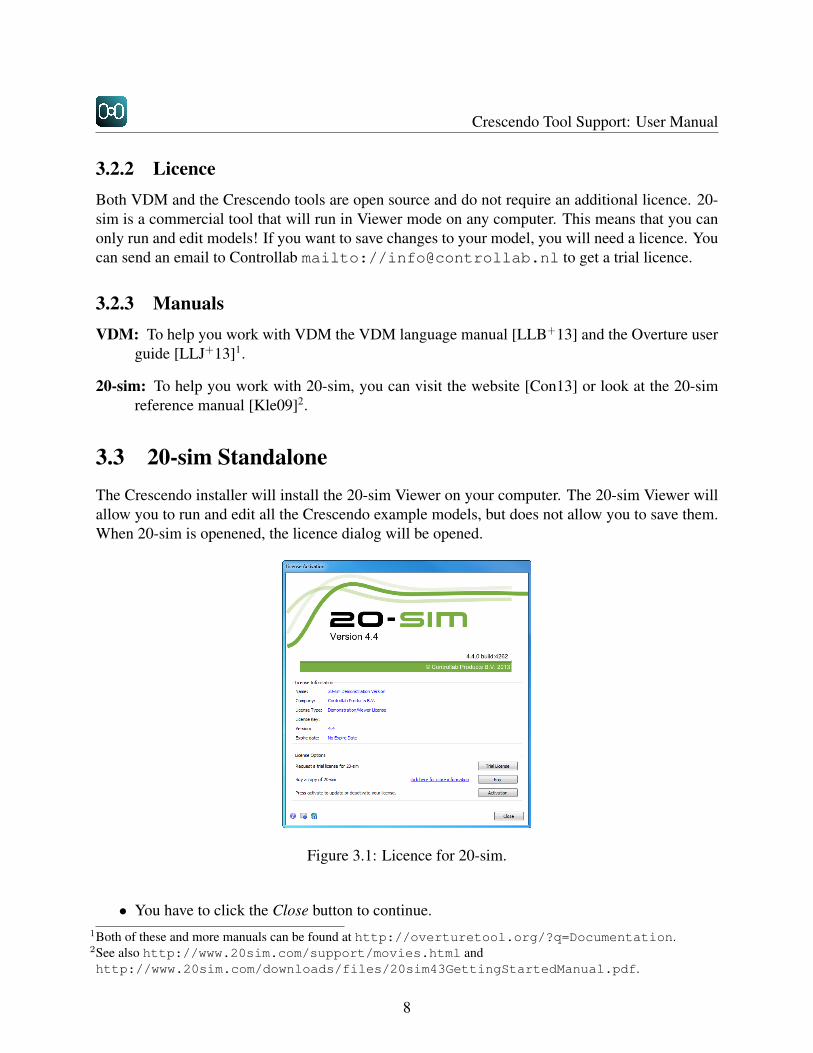
3.3 20-sim StandaloneThe Crescendo installer will install the 20-sim Viewer on your computer. The 20-sim Viewer willallow you to run and edit all the Crescendo example models, but does not allow you to save them.When 20-sim is openened, the licence dialog will be opened.
Figure 3.1: Licence for 20-sim.
• You have to click the Close button to continue.1Both of these and more manuals can be found at http://overturetool.org/?q=Documentation.2See also http://www.20sim.com/support/movies.html andhttp://www.20sim.com/downloads/files/20sim43GettingStartedManual.pdf.
8

CHAPTER 3. GETTING HOLD OF THE SOFTWARE
Unless you have purchased a license during model editing and simulation, the 20-sim Viewerwill remind you with a message:
9

Crescendo Tool Support: User Manual
10
Chapter 4
Quick Start with Crescendo
To help you get started with Crescendo this chapter gives you step by step instructions how toconfigure the software, get a basic WaterTankPeriodic example running and create your ownsimple project.
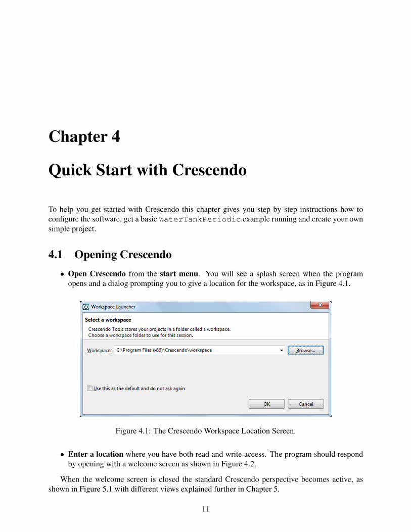
4.1 Opening Crescendo• Open Crescendo from the start menu. You will see a splash screen when the program
opens and a dialog prompting you to give a location for the workspace, as in Figure 4.1.
Figure 4.1: The Crescendo Workspace Location Screen.
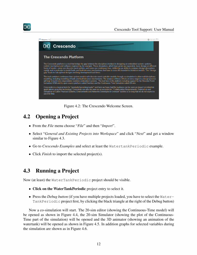
• Enter a location where you have both read and write access. The program should respondby opening with a welcome screen as shown in Figure 4.2.
When the welcome screen is closed the standard Crescendo perspective becomes active, asshown in Figure 5.1 with different views explained further in Chapter 5.
11
Crescendo Tool Support: User Manual
Figure 4.2: The Crescendo Welcome Screen.
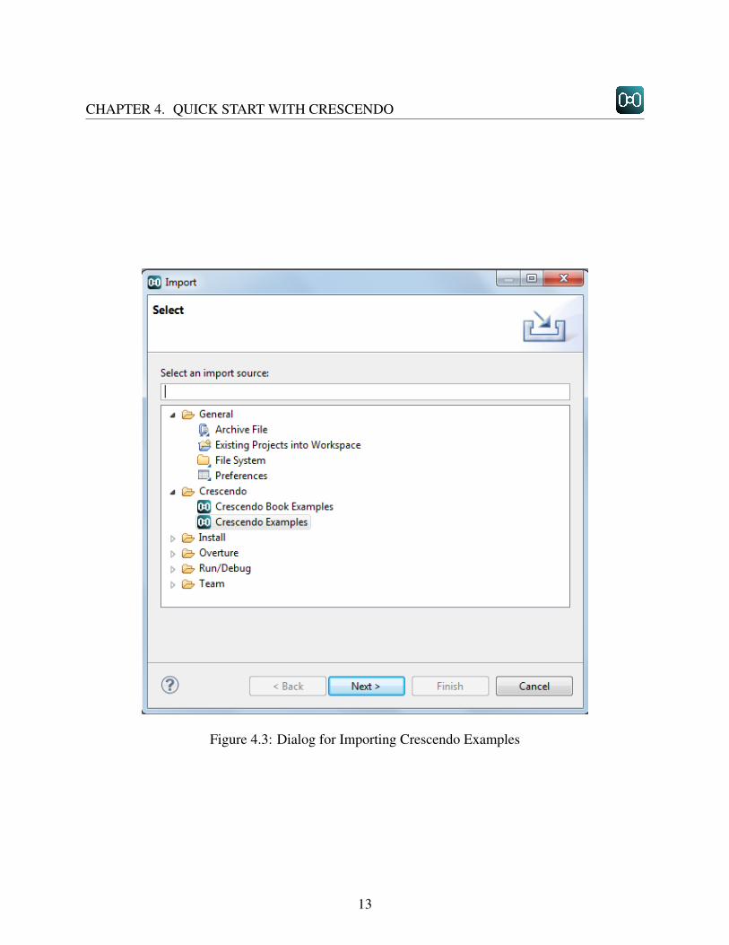
4.2 Opening a Project• From the File menu choose “File” and then “Import”.
• Select “General and Existing Projects into Workspace” and click “Next” and get a windowsimilar to Figure 4.3.
• Go to Crescendo Examples and select at least the WatertankPeriodic example.
• Click Finish to import the selected project(s).
4.3 Running a ProjectNow (at least) the WaterTankPeriodic project should be visible.
• Click on the WaterTankPeriodic project entry to select it.
• Press the Debug button (if you have multiple projects loaded, you have to select the Water-TankPeriodic project first, by clicking the black triangle at the right of the Debug button)
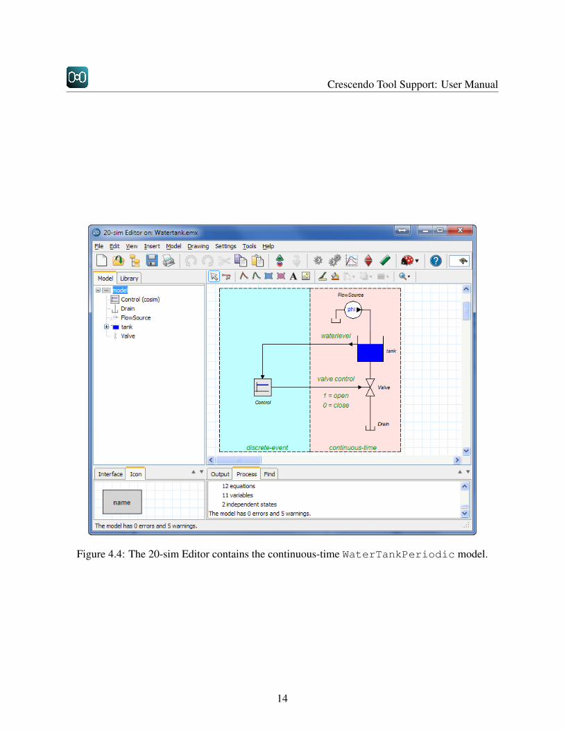
Now a co-simulation will start. The 20-sim editor (showing the Continuous-Time model) willbe opened as shown in Figure 4.4, the 20-sim Simulator (showing the plot of the Continuous-Time part of the simulation) will be opened and the 3D animator (showing an animation of thewatertank) will be opened as shown in Figure 4.5. In addition graphs for selected variables duringthe simulation are shown as in Figure 4.6.
12
CHAPTER 4. QUICK START WITH CRESCENDO
Figure 4.3: Dialog for Importing Crescendo Examples
13
Crescendo Tool Support: User Manual
Figure 4.4: The 20-sim Editor contains the continuous-time WaterTankPeriodic model.
14

CHAPTER 4. QUICK START WITH CRESCENDO
Figure 4.5: 20-sim can also show simulation results in a 3D animation.
15

Crescendo Tool Support: User Manual
Figure 4.6: The 20-sim Simulator shows the co-simulated plots.
16

Chapter 5
Editors and Management of Projects
5.1 The Crescendo Workbench
Eclipse is an open source platform based around a workbench that provides a common look and feelto a large collection of extension products. Thus, if a user is familiar with one Eclipse product,it will generally be easy to start using a different product on the same workbench. The Eclipseworkbench consists of several panels known as views, as shown in Figure 5.1. A collection ofpanels is called a perspective. The figure below shows the standard Crescendo perspective. TheCrescendo perspective consists of a set of views for managing Crescendo projects and viewing andediting files in a project. Different perspectives are available in Crescendo based on the task thatyou are doing. In the subsections below the different views of the standard Crescendo perspectivewill be presented.
Figure 5.1: Standard Crescendo Perspective.
17
Crescendo Tool Support: User Manual
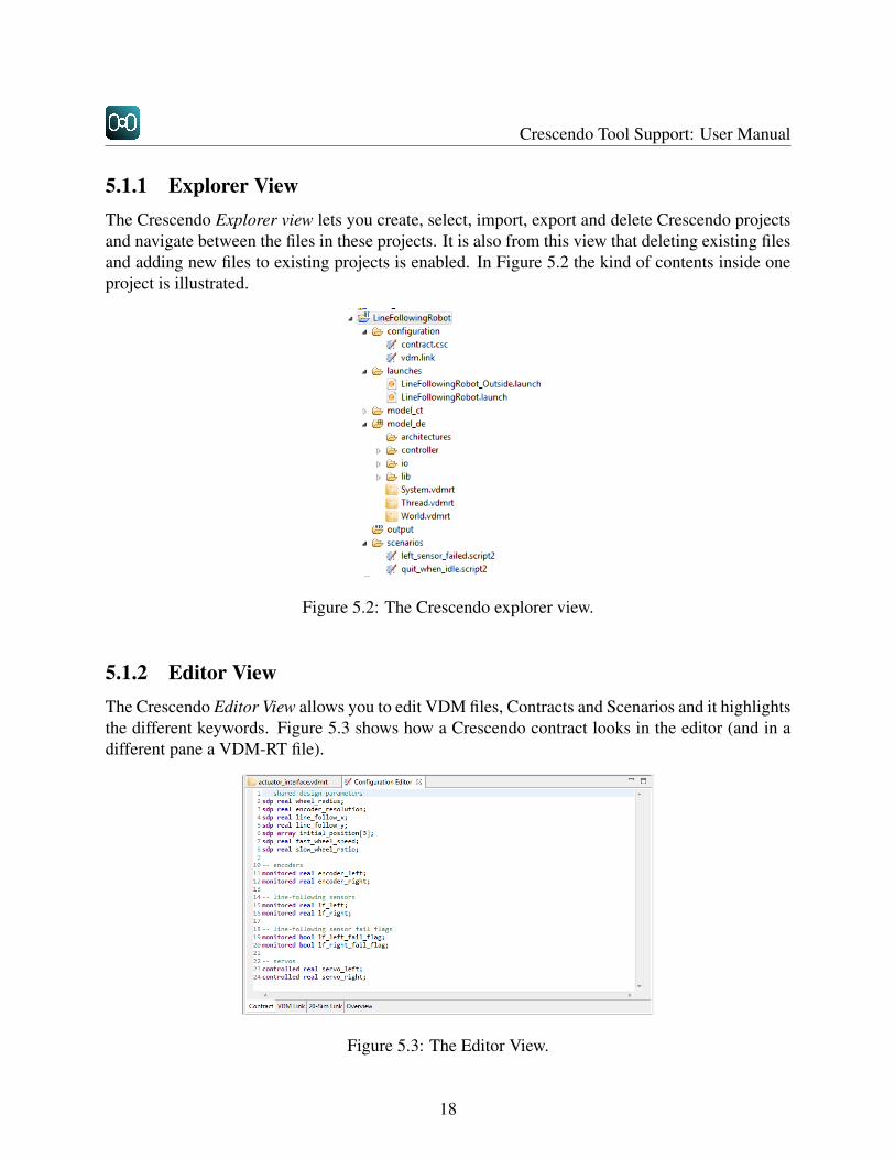
5.1.1 Explorer ViewThe Crescendo Explorer view lets you create, select, import, export and delete Crescendo projectsand navigate between the files in these projects. It is also from this view that deleting existing filesand adding new files to existing projects is enabled. In Figure 5.2 the kind of contents inside oneproject is illustrated.
Figure 5.2: The Crescendo explorer view.
5.1.2 Editor ViewThe Crescendo Editor View allows you to edit VDM files, Contracts and Scenarios and it highlightsthe different keywords. Figure 5.3 shows how a Crescendo contract looks in the editor (and in adifferent pane a VDM-RT file).
Figure 5.3: The Editor View.
18
CHAPTER 5. EDITORS AND MANAGEMENT OF PROJECTS
5.1.3 Outline View
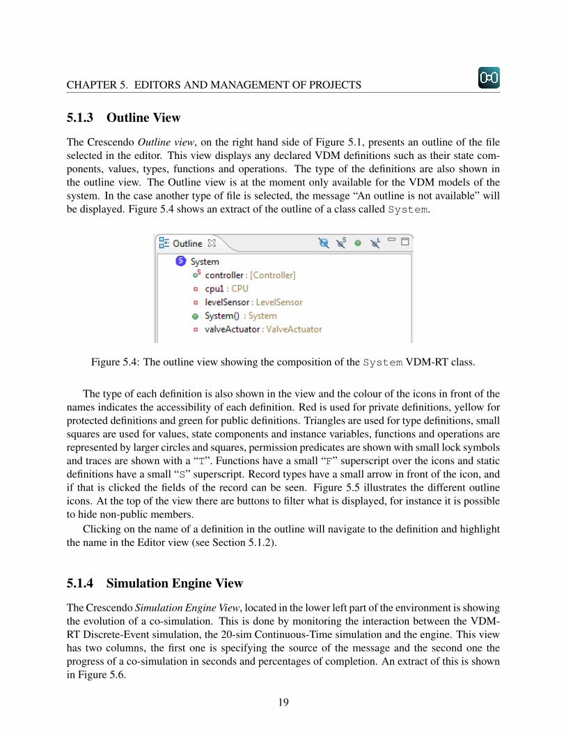
The Crescendo Outline view, on the right hand side of Figure 5.1, presents an outline of the fileselected in the editor. This view displays any declared VDM definitions such as their state com-ponents, values, types, functions and operations. The type of the definitions are also shown inthe outline view. The Outline view is at the moment only available for the VDM models of thesystem. In the case another type of file is selected, the message “An outline is not available” willbe displayed. Figure 5.4 shows an extract of the outline of a class called System.
Figure 5.4: The outline view showing the composition of the System VDM-RT class.
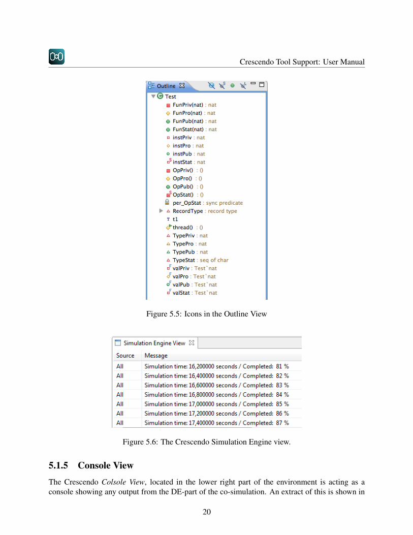
The type of each definition is also shown in the view and the colour of the icons in front of thenames indicates the accessibility of each definition. Red is used for private definitions, yellow forprotected definitions and green for public definitions. Triangles are used for type definitions, smallsquares are used for values, state components and instance variables, functions and operations arerepresented by larger circles and squares, permission predicates are shown with small lock symbolsand traces are shown with a “T”. Functions have a small “F” superscript over the icons and staticdefinitions have a small “S” superscript. Record types have a small arrow in front of the icon, andif that is clicked the fields of the record can be seen. Figure 5.5 illustrates the different outlineicons. At the top of the view there are buttons to filter what is displayed, for instance it is possibleto hide non-public members.
Clicking on the name of a definition in the outline will navigate to the definition and highlightthe name in the Editor view (see Section 5.1.2).
5.1.4 Simulation Engine View
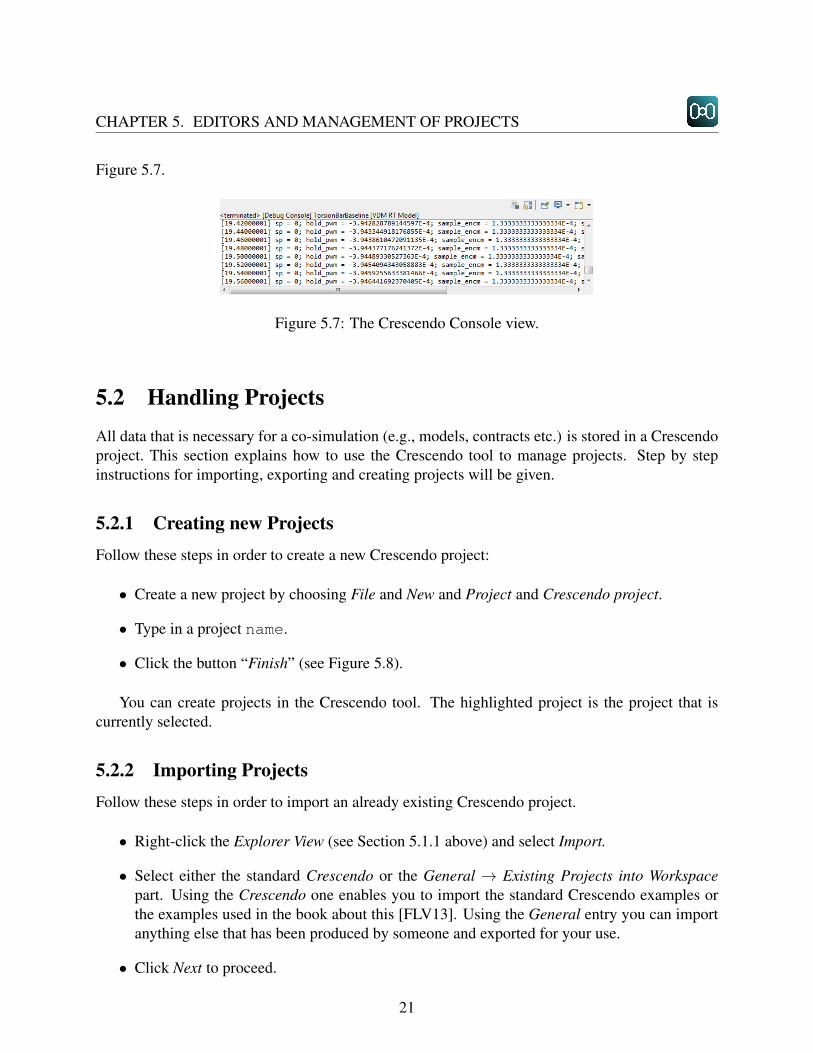
The Crescendo Simulation Engine View, located in the lower left part of the environment is showingthe evolution of a co-simulation. This is done by monitoring the interaction between the VDM-RT Discrete-Event simulation, the 20-sim Continuous-Time simulation and the engine. This viewhas two columns, the first one is specifying the source of the message and the second one theprogress of a co-simulation in seconds and percentages of completion. An extract of this is shownin Figure 5.6.
19
Crescendo Tool Support: User Manual
Figure 5.5: Icons in the Outline View
Figure 5.6: The Crescendo Simulation Engine view.
5.1.5 Console View
The Crescendo Colsole View, located in the lower right part of the environment is acting as aconsole showing any output from the DE-part of the co-simulation. An extract of this is shown in
20
CHAPTER 5. EDITORS AND MANAGEMENT OF PROJECTS
Figure 5.7.
Figure 5.7: The Crescendo Console view.
5.2 Handling ProjectsAll data that is necessary for a co-simulation (e.g., models, contracts etc.) is stored in a Crescendoproject. This section explains how to use the Crescendo tool to manage projects. Step by stepinstructions for importing, exporting and creating projects will be given.
5.2.1 Creating new ProjectsFollow these steps in order to create a new Crescendo project:
• Create a new project by choosing File and New and Project and Crescendo project.
• Type in a project name.
• Click the button “Finish” (see Figure 5.8).
You can create projects in the Crescendo tool. The highlighted project is the project that iscurrently selected.
5.2.2 Importing ProjectsFollow these steps in order to import an already existing Crescendo project.
• Right-click the Explorer View (see Section 5.1.1 above) and select Import.
• Select either the standard Crescendo or the General → Existing Projects into Workspacepart. Using the Crescendo one enables you to import the standard Crescendo examples orthe examples used in the book about this [FLV13]. Using the General entry you can importanything else that has been produced by someone and exported for your use.
• Click Next to proceed.
21

Crescendo Tool Support: User Manual
Figure 5.8: Create project dialog.
Figure 5.9: Import project dialog.
22

CHAPTER 5. EDITORS AND MANAGEMENT OF PROJECTS
• If one of the Crescendo options is taken, a list of the potential projects to import will appear.Otherwise if the General one was selected you shall select the the radio button “Select rootdirectory” if the project is uncompressed. Otherwise select the the radio button “Selectarchive file” if the project is contained in a compressed archive file. Afterwards, use theBrowse button to locate the project.
• A compressed archive file may contain multiple projects. Select the projects that you wantto import as shown in Figure 5.10.
• Click the Finish button. The imported project will appear on the Crescendo explorer view.
Figure 5.10: Import projects.
5.2.3 Exporting ProjectsFollow these steps in order to export a Crescendo project:
23
Crescendo Tool Support: User Manual
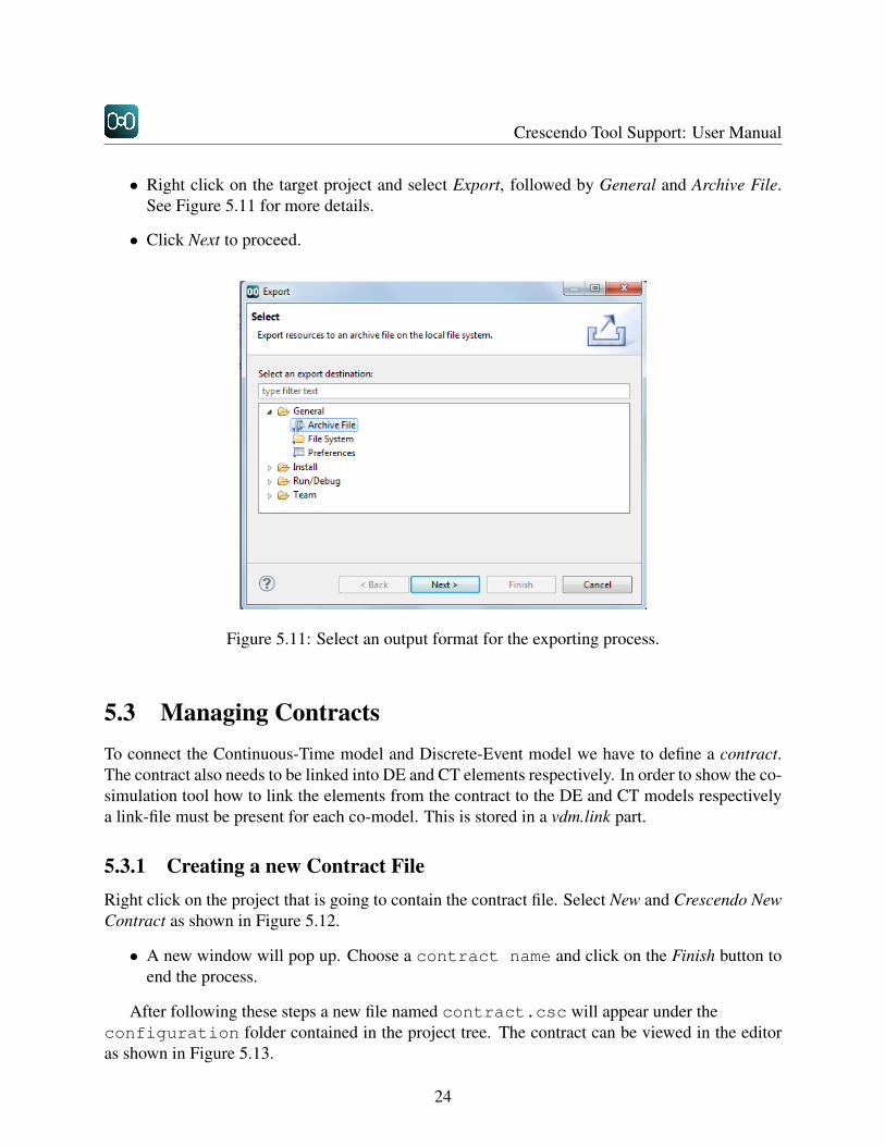
• Right click on the target project and select Export, followed by General and Archive File.See Figure 5.11 for more details.
• Click Next to proceed.
Figure 5.11: Select an output format for the exporting process.
5.3 Managing ContractsTo connect the Continuous-Time model and Discrete-Event model we have to define a contract.The contract also needs to be linked into DE and CT elements respectively. In order to show the co-simulation tool how to link the elements from the contract to the DE and CT models respectivelya link-file must be present for each co-model. This is stored in a vdm.link part.
5.3.1 Creating a new Contract FileRight click on the project that is going to contain the contract file. Select New and Crescendo NewContract as shown in Figure 5.12.
• A new window will pop up. Choose a contract name and click on the Finish button toend the process.
After following these steps a new file named contract.csc will appear under theconfiguration folder contained in the project tree. The contract can be viewed in the editoras shown in Figure 5.13.
24

CHAPTER 5. EDITORS AND MANAGEMENT OF PROJECTS
Figure 5.12: Choosing a new Crescendo contract.
Figure 5.13: The Editor with a new contract.
5.3.2 Contents of a ContractA contract between a CT and a DE model can contain the following kinds of information:
Design parameters: These are typically values which indicate the properties of components (e.g.size, weight, temperature). A designer would like to explore different values of these param-eters in order to find an optimal solution to the challenge he is working on. The actual valuesfor the shared design parameters are set outside the contract in a separate file.
Variables: The variables are the active interface between the CT and DE models so these indicatethe variables that change during one simulation. Variables typically represent sensor readingsand signals to actuators.
Events: Events can be triggered in the CT world. They will stop the simulation before the al-lowed time slice is completed. The co-simulation engine will then allow the DE simulator totake action but only until the point where the event has been raised. The events are used inthe contract in order to support event-based triggering and not just time-triggered scheduling.
25

Crescendo Tool Support: User Manual
The syntax for contracts follow the following rules:
〈contract〉 ::= parameters | variables | events;
〈parameters〉 ::= ‘shared design parameter’ type identifier ‘;’ | ‘sdp’ type identifier‘;’
〈variables〉 ::= kind type identifier ‘;’ | kind ‘matrix’ identifier shape ‘;’
〈shape〉 ::= ‘[’ ‘integer’ ‘,’ ‘integer’)* ‘]’
〈events〉 ::= ‘event’, identifier, ‘;’
〈type〉 ::= ‘real’ | ‘bool’ ;
〈identifier〉 ::= initial letter (following letter)* ;
〈kind〉 ::= ‘monitored’ | ‘controlled’ ;
〈value〉 ::= float | boolean literal ;
〈boolean literal〉 ::= ‘true’ | ‘false’ ;
In the following listing, an extract from the contract file provided with the WaterTank-Periodic example is shown.
-- Shared design parameterssdp real maxlevel;sdp real minlevel;
-- Monitored variables (seen from the DE controller)monitored real level;
-- Controlled variables (seen from the DE controller)controlled bool valve;
Matrices
It is also possible to exchange matrices between DE and CT models. To be able to do this, a matrixneeds to be declared in the contract. The adopted syntax is similar to 20-sim, where the shape ofthe matrix is indicated by a sequence of integers [m1,...,mn]. For example, to declare a 2x2 matrixnamed M which is monitored the following must be added to the contract:
monitored matrix M[2,2];
26
CHAPTER 5. EDITORS AND MANAGEMENT OF PROJECTS
In VDM matrices of “n” dimensions (m1 *... * mn) are represented as (seq of ...seq of real). So a 2x2 matrix is represented as a (seq of seq of real). The contractmatrix variables are linked in the same manner as any other variable but the target variable needsto be of the correct type, in our case seq of seq of real. At the VDM level this wouldtypically be declared as:�instance variables
M: seq of seq of real := [[0.0,0.0],[0.0,0.0]];� �Arrays
Arrays which are limited to one dimension can be declared in the same style:
monitored array position[3];
Arrays are basically matrices limited to one dimension.
5.3.3 Error Detection in the Contract/Link File
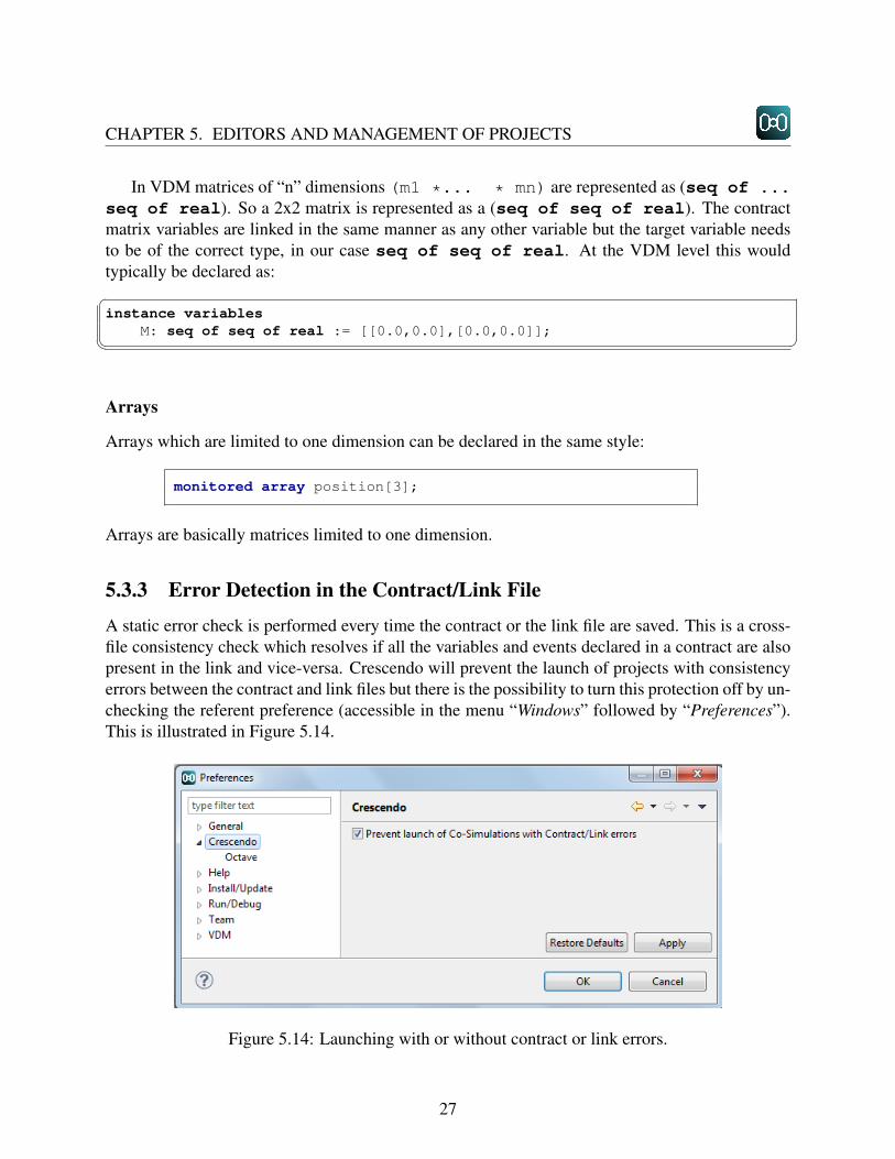
A static error check is performed every time the contract or the link file are saved. This is a cross-file consistency check which resolves if all the variables and events declared in a contract are alsopresent in the link and vice-versa. Crescendo will prevent the launch of projects with consistencyerrors between the contract and link files but there is the possibility to turn this protection off by un-checking the referent preference (accessible in the menu “Windows” followed by “Preferences”).This is illustrated in Figure 5.14.
Figure 5.14: Launching with or without contract or link errors.
27
Crescendo Tool Support: User Manual
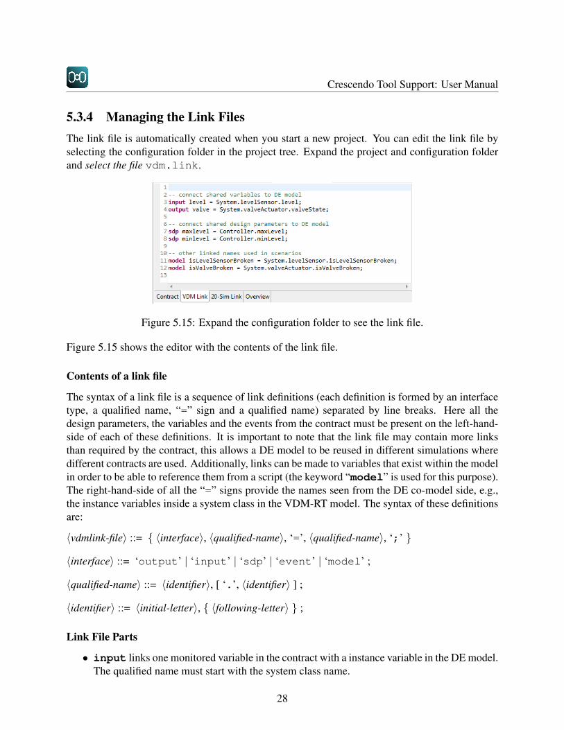
5.3.4 Managing the Link FilesThe link file is automatically created when you start a new project. You can edit the link file byselecting the configuration folder in the project tree. Expand the project and configuration folderand select the file vdm.link.
Figure 5.15: Expand the configuration folder to see the link file.
Figure 5.15 shows the editor with the contents of the link file.
Contents of a link file
The syntax of a link file is a sequence of link definitions (each definition is formed by an interfacetype, a qualified name, “=” sign and a qualified name) separated by line breaks. Here all thedesign parameters, the variables and the events from the contract must be present on the left-hand-side of each of these definitions. It is important to note that the link file may contain more linksthan required by the contract, this allows a DE model to be reused in different simulations wheredifferent contracts are used. Additionally, links can be made to variables that exist within the modelin order to be able to reference them from a script (the keyword “model” is used for this purpose).The right-hand-side of all the “=” signs provide the names seen from the DE co-model side, e.g.,the instance variables inside a system class in the VDM-RT model. The syntax of these definitionsare:
〈vdmlink-file〉 ::= { 〈interface〉, 〈qualified-name〉, ‘=’, 〈qualified-name〉, ‘;’ }
〈interface〉 ::= ‘output’ | ‘input’ | ‘sdp’ | ‘event’ | ‘model’ ;
〈qualified-name〉 ::= 〈identifier〉, [ ‘.’, 〈identifier〉 ] ;
〈identifier〉 ::= 〈initial-letter〉, { 〈following-letter〉 } ;
Link File Parts
• input links one monitored variable in the contract with a instance variable in the DE model.The qualified name must start with the system class name.
28

CHAPTER 5. EDITORS AND MANAGEMENT OF PROJECTS
• output links one controlled variable in the contract with an instance variable in the DEmodel. The qualified name must start with the system class name.
• sdp links a shared design parameter in the contract with a value in the DE model. Thequalified name can start with any class name and the referenced value must be a VDM value.
• model links a “name” and a variable in the VDM model. The name can then be used toreference the variable in scripts. The qualified name must start with the system class name.
The vdm.link file for the WaterTankPeriodic example looks as:
-- connect shared variables to DE modelinput level = System.levelSensor.level;output valve = System.valveActuator.valveState;
-- connect shared design parameters to DE modelsdp maxlevel = Controller.maxLevel;sdp minlevel = Controller.minLevel;
-- other linked names used in scenariosmodel isLevelSensorBroken =
System.levelSensor.isLevelSensorBroken;model isValveBroken =
System.valveActuator.isValveBroken;
CT Model
On the 20-sim side, a link file is not used, but still, the variables/parameters need to be declared ina certain way inside the 20-sim model in order to carry out the co-simulation. Variables used inthe co-simulation, need to be in the externals field and marked as global. Depending if theyare used as input or output they need to be marked import or export respectively. Example:
externalsreal global export level;real global import valve;
The parameters to be shared across the two models need to be marked with the keyword shared.Example:
parametersreal aParam (’shared’) = 5;
29

Crescendo Tool Support: User Manual
Events need to be marked using the event keyword this marks the variable that it used as re-turn value of the event function to be an event variable. The keywords eventdown and eventupare used as in standalone 20-sim models. Example:
variablesboolean minLevelReached (’event’);
equationsmaxLevelReached = eventup(levelIn-maxlevel);
5.3.5 Contract OverviewAn overview of the contract can be seen on the last tab of multi-editor as shown in Figure 5.16.
Figure 5.16: Overview of contract information.
In this view it is possible to see which variable from the DE side is connected to which contractvariable and transitively to which CT variable. The form they are presented is:
VDM variable <-> Contract Variable <-> 20-sim variable
The “not checked” warning appears next to the 20-sim variables because at this moment is notpossible to static check if the variables exist in the 20-sim model.
30

Chapter 6
Co-Simulation
6.1 Debug ConfigurationBefore starting a co-simulation, a debug configuration must be created if a launch configurationis not already available. The purpose of this is to define where the Continuous Time and DiscreteEvent models are located, as well as the scenario file and the simulation time. In this section wewill go through each pane in the debug configuration.
6.1.1 Creating a New Debug Configuration• Select the project for which you want to create a Debug Configuration.
• Press the small arrow next to the debug icon at the top of the the Crescendo Tool.
• A drop-down menu will appear, in which the option Debug configuration has to be selected,and as a consequence a new window will appear as shown in Figure 6.1.
• Select the option Co-Sim Launch and New Configuration
Now a window will show up as Figure 6.2 where you can enter the settings of the debugconfiguration. We will describe all the tabs that can be configured before running a co-simulation.
6.1.2 Main TabOnce the project is found and selected, the paths for both Discrete Event model will be automati-cally set. Since multiple Continuous Time models could be present the Browse button to select theone you would like to use.
The Main Tab is where the project to co-simulate is selected. This can be done by pressingthe “Browse...” button. After selecting the wanted project, the DE model path is automaticallyfilled since it is only possible to have one DE model in the model de folder. Though the CTmodel path needs to be selected using the Browse... button. If a scenario should be used (see
31

Crescendo Tool Support: User Manual
Figure 6.1: Select a new debug configuration.
Figure 6.2: The Main tab of the Debug Configuration.
Section6.3 for more information on scenarios), it is possible to select which one in the SimulationConfiguration section. The total simulation time should be a number greater than zero to be ableto run the co-simulation.
32

CHAPTER 6. CO-SIMULATION
6.1.3 Shared Design Parameters TabAn important feature of the debug configuration is the possibility to view and modify the shareddesign parameters of the co-simulation. This is configured in Figure 6.3.
Figure 6.3: The Shared Design Parameters tab of the Debug Configuration.
In the Shared Design Parameters tab, a list of the parameters used in the simulation can beviewed. For the variables to appear for the first time the button “Synchronize with contract” needsto be pressed. Every time the shared design parameters are changed in the contract, the buttonmust be pressed again in order to synchronize the view with the contract.
For the variables present in the table it is possible to decide which values they will have whenthe co-simulation starts. Figure 6.3 shows the Shared Design Parameters tab for a project that hasan array[3] as a shared design parameter.
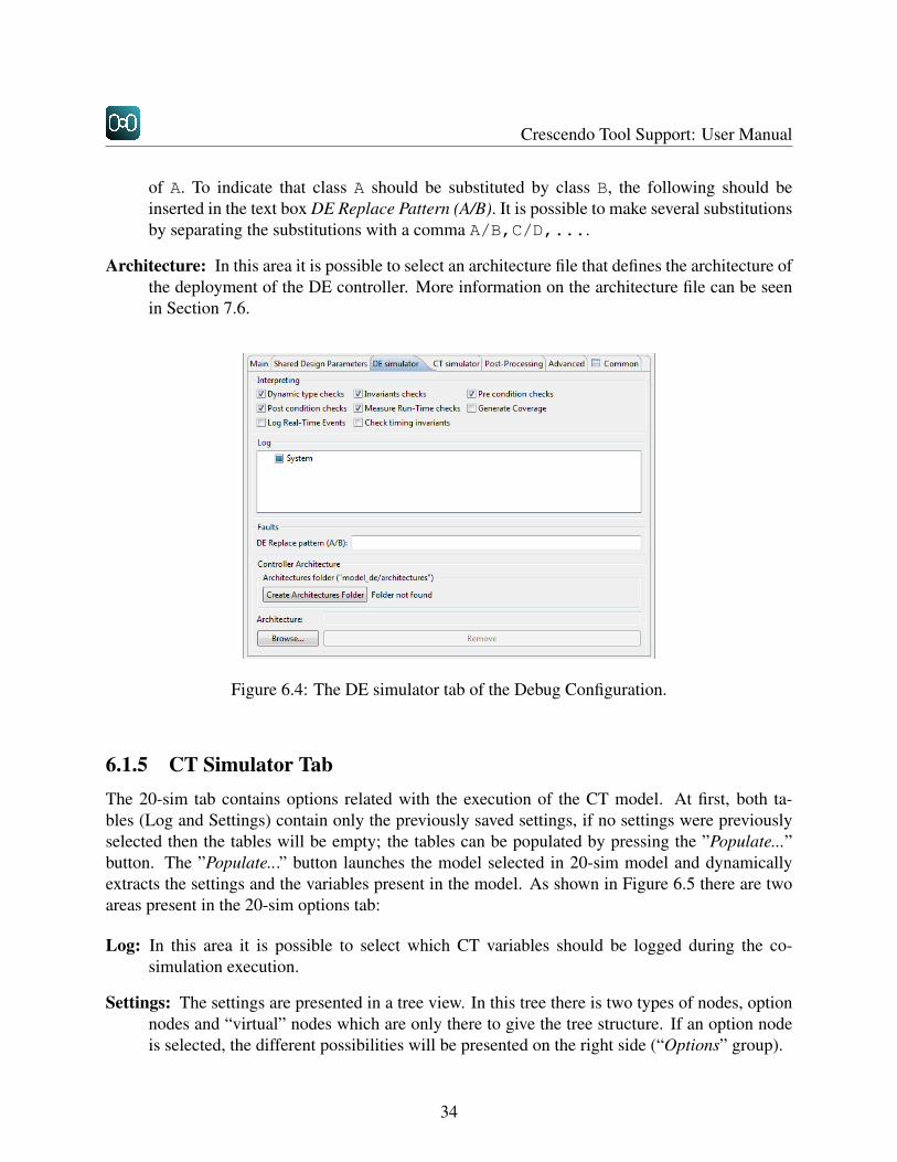
6.1.4 DE Simulator TabThe DE Simulator tab is the place where runtime options for the DE part of the model can beactivated and deactivated. It is divided in 4 options groups:
Interpreting: These are options related to the interpretation of the DE models. Certain checksand also the generation of reports such as coverage or the real-time events can be turnedon and off. Usage of these options are further explained in the Overture/VDM user manual[LLJ+13].
Log: In this group it is possible to select variables from the DE model that should be logged duringthe simulation. To find more details about this feature, see Section 6.4.
Faults: In this group it is possible to select a class A to replace a class B before the co-simulationstart. The intention is to experiment with faulty modules that can be substituted by the non-faulty model. To make sure there will be no run-time exceptions, class B should be subclass
33
Crescendo Tool Support: User Manual
of A. To indicate that class A should be substituted by class B, the following should beinserted in the text box DE Replace Pattern (A/B). It is possible to make several substitutionsby separating the substitutions with a comma A/B,C/D,....
Architecture: In this area it is possible to select an architecture file that defines the architecture ofthe deployment of the DE controller. More information on the architecture file can be seenin Section 7.6.
Figure 6.4: The DE simulator tab of the Debug Configuration.
6.1.5 CT Simulator TabThe 20-sim tab contains options related with the execution of the CT model. At first, both ta-bles (Log and Settings) contain only the previously saved settings, if no settings were previouslyselected then the tables will be empty; the tables can be populated by pressing the ”Populate...”button. The ”Populate...” button launches the model selected in 20-sim model and dynamicallyextracts the settings and the variables present in the model. As shown in Figure 6.5 there are twoareas present in the 20-sim options tab:
Log: In this area it is possible to select which CT variables should be logged during the co-simulation execution.
Settings: The settings are presented in a tree view. In this tree there is two types of nodes, optionnodes and “virtual” nodes which are only there to give the tree structure. If an option nodeis selected, the different possibilities will be presented on the right side (“Options” group).
34

CHAPTER 6. CO-SIMULATION
Figure 6.5: The CT simulator tab of the Debug Configuration.
6.2 Post-Processing Tab
The post processing tab shows the options available for the post-processing phase (see Figure 6.6).
Figure 6.6: Post-processing tab for debug configuration.
“Show plot automatically when the script runs” with this option enabled, the Octave script thatis generated after each run will contain the commands to show the plot automatically, i.e., simplyrunning the script will show the plots. For more information on the use of Octave, please seeSection 8.1.
6.2.1 Advanced Tab
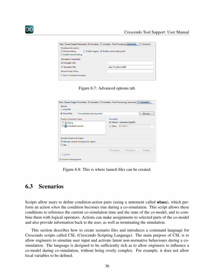
The advanced tab is reserved for developers, extra debug information can be turned on or off inthis tab (see Figure 6.7).
6.2.2 Common Tab
The Common tab is a standard Eclipse tab which, for example, allows users to save the debugconfigurations into files so that they can be shared with others. Figure 6.8 shows how to produce alaunch file that can be shared with others.
35
Crescendo Tool Support: User Manual
Figure 6.7: Advanced options tab.
Figure 6.8: This is where launch files can be created.
6.3 Scenarios
Scripts allow users to define condition-action pairs (using a statement called when), which per-form an action when the condition becomes true during a co-simulation. This script allows theseconditions to reference the current co-simulation time and the state of the co-model, and to com-bine them with logical operators. Actions can make assignments to selected parts of the co-modeland also provide information back to the user, as well as terminating the simulation.
This section describes how to create scenario files and introduces a command language forCrescendo scripts called CSL (Crescendo Scripting Language). The main purpose of CSL is toallow engineers to simulate user input and activate latent non-normative behaviours during a co-simulation. The language is designed to be sufficiently rich as to allow engineers to influence aco-model during co-simulation, without being overly complex. For example, it does not allowlocal variables to be defined.
36
CHAPTER 6. CO-SIMULATION
6.3.1 Creating a New Scenario FileFollow these steps in order to create a new scenario file:
• Right-click on the project that is going to contain the contract file. Select “New” andCrescendo New Scenario.
• A new window will pop up, named Scenario Wizard. Select the current project by clickingon the “Browse” button. Click on the Finish button to end the process.
After following these steps a new file named Scenario.script2 will be placed under the scenariosfolder.
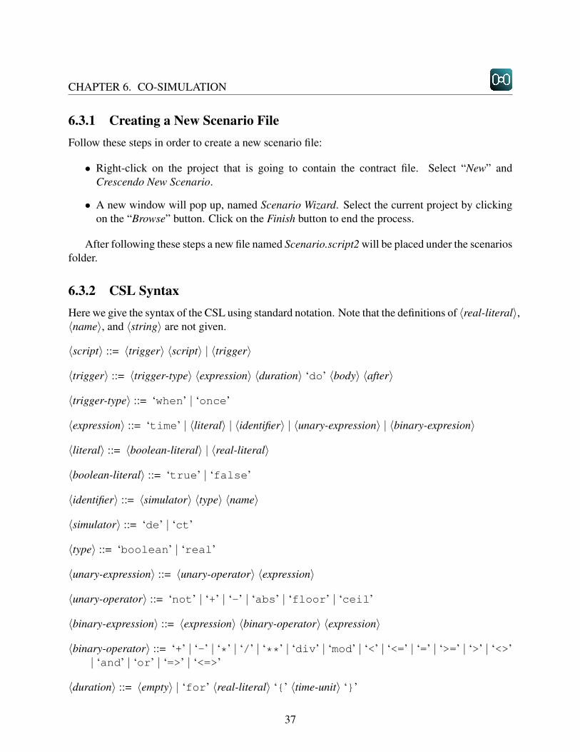
6.3.2 CSL SyntaxHere we give the syntax of the CSL using standard notation. Note that the definitions of 〈real-literal〉,〈name〉, and 〈string〉 are not given.
〈script〉 ::= 〈trigger〉 〈script〉 | 〈trigger〉
〈trigger〉 ::= 〈trigger-type〉 〈expression〉 〈duration〉 ‘do’ 〈body〉 〈after〉
〈trigger-type〉 ::= ‘when’ | ‘once’
〈expression〉 ::= ‘time’ | 〈literal〉 | 〈identifier〉 | 〈unary-expression〉 | 〈binary-expresion〉
〈literal〉 ::= 〈boolean-literal〉 | 〈real-literal〉
〈boolean-literal〉 ::= ‘true’ | ‘false’
〈identifier〉 ::= 〈simulator〉 〈type〉 〈name〉
〈simulator〉 ::= ‘de’ | ‘ct’
〈type〉 ::= ‘boolean’ | ‘real’
〈unary-expression〉 ::= 〈unary-operator〉 〈expression〉
〈unary-operator〉 ::= ‘not’ | ‘+’ | ‘-’ | ‘abs’ | ‘floor’ | ‘ceil’
〈binary-expression〉 ::= 〈expression〉 〈binary-operator〉 〈expression〉
〈binary-operator〉 ::= ‘+’ | ‘-’ | ‘*’ | ‘/’ | ‘**’ | ‘div’ | ‘mod’ | ‘<’ | ‘<=’ | ‘=’ | ‘>=’ | ‘>’ | ‘<>’| ‘and’ | ‘or’ | ‘=>’ | ‘<=>’
〈duration〉 ::= 〈empty〉 | ‘for’ 〈real-literal〉 ‘{’ 〈time-unit〉 ‘}’
37

Crescendo Tool Support: User Manual
〈time-unit〉 ::= ‘us’ | ‘ms’ | ‘s’ | ‘m’ | ‘h’
〈body〉 ::= 〈block〉 | 〈statement〉
〈block〉 ::= ‘(’ 〈statement-list〉 ‘)’
〈statement-list〉 ::= 〈statement〉 | 〈statement〉 ‘;’ 〈statement-list〉
〈statement〉 ::= 〈identifier〉 ‘:=’ 〈expression〉| ‘print’ 〈string〉| ‘warn’ 〈string〉| ‘error’ 〈string〉| ‘quit’
〈after〉 ::= ‘after’ 〈revert-list〉
〈revert-list〉 ::= ‘revert’ 〈identifier〉 | ‘revert’ 〈identifier〉 ‘;’ 〈revert-list〉
6.3.3 CSL ExamplesThe following introduces a series of simple examples that demonstrate the features of this scriptlanguage.
when time = 5 do(de real x := 10;);
The time keyword yields the current co-simulation time. The de keyword indicates that xresides (at the top level) in the DE model. Naturally, the ct keyword is used to indicate the CTmodel. Comments may also be included:
when time = 5 do// comment(ct real y := true;);
Statements can also be grouped in blocks (surrounded by parentheses and separated by semi-colons. Expressions of time can optionally include a unit (e.g. milliseconds) given in curly braces.Units are assumed to be in seconds if no unit is given. The engineer may output messages to thetool (or to a log in batch mode) with the print statement:
when time = 900 {ms} do(de real x := 10;ct real y := true;print "Co-simulation time reached 900 ms.";
38

CHAPTER 6. CO-SIMULATION
);
Logical operators can be used in expressions. When the condition becomes true, the state-ment(s) in the do clause will execute.
when time >= 10 and time < 15 do(print "Co-simulation time reached 10 seconds.";)
If the condition becomes false again, the optional after clause will execute once. Note thatblock statements do not permit local variables to be defined. Since this script language does notallow local variables to be defined, a special statement, revert, may be used in an after clauseto change a value back to what it was when the do clause executed. Note that comments may alsobe included:
when time >= 10 and time < 15 do( // assume x = 5de real x := 10;
)after (revert de real x;);
The engineer can reference co-model state in conditions and assignment and revert statements.The state that can be referred is either for VDM specified with the model keyword in the linkfile or for 20-sim marked as global (note 20-sim access is not yet implemented). Additionally allshared variables can be accessed with the contract name and used in conditions, assignments orrevert statements.
It is also possible to have some statements executed exactly once, on the first time a conditionis detected. This is achieved using the once keyword instead of when.
once de real x >= 500 do(// set some flagde bool flag = true;print "First time x exceeds 500";)
6.4 LogfilesWhen starting a simulation, it is possible to select a set of variables that are logged during theco-simulation. At the time this manual was written there is only the possibility of logging DEvariables; support to log CT variables will be added later. The result of this logging is a CSV file(comma separated values), which can be post processed with regular office tools.
39

Crescendo Tool Support: User Manual
6.4.1 DE VariablesThe variables of the DE model to log can be selected in the tab VDM Options presented in Fig-ure 6.9. If a model does not contain type errors, this tab will display all instance variables that areaccessible from the VDM system class.
Figure 6.9: VDM Options tab permits the selection of variables to log.
Checking the box next to a variable enables the logging of that variable. Currently it is only pos-sible to log variables with basic types (all types except objects). For the WatertankPeriodicexample, if we use the configuration shown above, a file with the contents as follows is generated:
40

CHAPTER 6. CO-SIMULATION
time,levelSensor.fault,levelSensor.level,valveActuator.valveState0.0,0,0,00.01,0,0.01,00.01,0,0.02,00.02,0,0.03,00.03,0,0.03,0...
The first column is the simulation time and the following columns contain the value of thevariable at that given moment. A CSV file can be better visualized, for example, in 20-sim, Excelor other software capable of opening this format. For convenience, the first line of the file providesthe names of the exported variables.
41

Crescendo Tool Support: User Manual
42
Chapter 7
Design Space Exploration
In order to support Design Space Exploration (DSE), the Automated Co-model Analysis (ACA)feature can automatically running many different co-simulations with minimal user intervention.The ACA feature enables the user to select different configurations for each individual parts of theco-model and then runs the co-simulation combining all possible configurations that were selectedby the user.
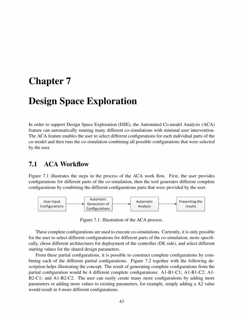
7.1 ACA WorkflowFigure 7.1 illustrates the steps in the process of the ACA work flow. First, the user providesconfigurations for different parts of the co-simulation, then the tool generates different completeconfigurations by combining the different configurations parts that were provided by the user.
Figure 7.1: Illustration of the ACA process.
These complete configurations are used to execute co-simulations. Currently, it is only possiblefor the user to select different configurations for different parts of the co-simulation, more specifi-cally, chose different architectures for deployment of the controller (DE side), and select differentstarting values for the shared design parameters.
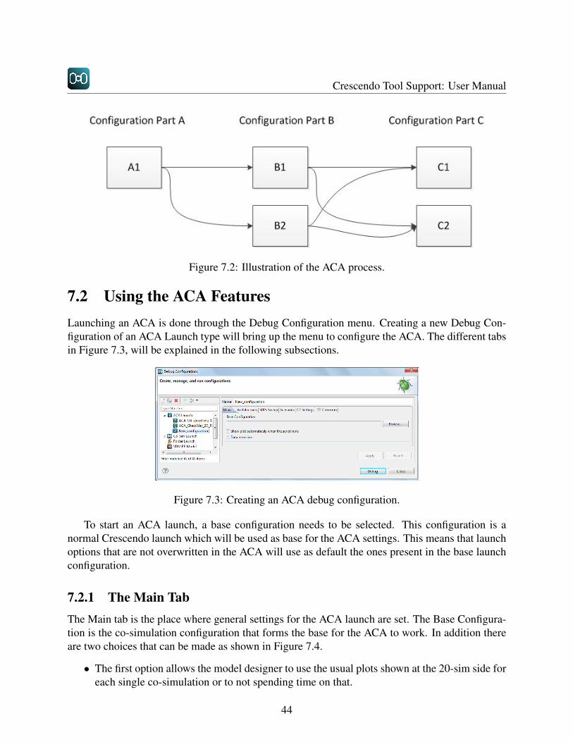
From these partial configurations, it is possible to construct complete configurations by com-bining each of the different partial configurations. Figure 7.2 together with the following de-scription helps illustrating the concept. The result of generating complete configurations from thepartial configuration would be 4 different complete configurations: A1-B1-C1; A1-B1-C2; A1-B2-C1; and A1-B2-C2. The user can easily create many more configurations by adding moreparameters or adding more values to existing parameters, for example, simply adding a A2 valuewould result in 4 more different configurations.
43
Crescendo Tool Support: User Manual
Figure 7.2: Illustration of the ACA process.
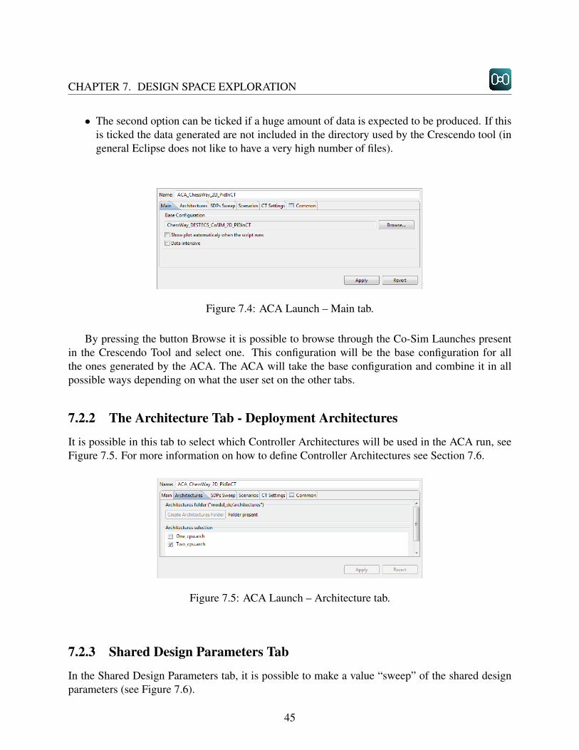
7.2 Using the ACA FeaturesLaunching an ACA is done through the Debug Configuration menu. Creating a new Debug Con-figuration of an ACA Launch type will bring up the menu to configure the ACA. The different tabsin Figure 7.3, will be explained in the following subsections.
Figure 7.3: Creating an ACA debug configuration.
To start an ACA launch, a base configuration needs to be selected. This configuration is anormal Crescendo launch which will be used as base for the ACA settings. This means that launchoptions that are not overwritten in the ACA will use as default the ones present in the base launchconfiguration.
7.2.1 The Main TabThe Main tab is the place where general settings for the ACA launch are set. The Base Configura-tion is the co-simulation configuration that forms the base for the ACA to work. In addition thereare two choices that can be made as shown in Figure 7.4.
• The first option allows the model designer to use the usual plots shown at the 20-sim side foreach single co-simulation or to not spending time on that.
44
CHAPTER 7. DESIGN SPACE EXPLORATION
• The second option can be ticked if a huge amount of data is expected to be produced. If thisis ticked the data generated are not included in the directory used by the Crescendo tool (ingeneral Eclipse does not like to have a very high number of files).
Figure 7.4: ACA Launch – Main tab.
By pressing the button Browse it is possible to browse through the Co-Sim Launches presentin the Crescendo Tool and select one. This configuration will be the base configuration for allthe ones generated by the ACA. The ACA will take the base configuration and combine it in allpossible ways depending on what the user set on the other tabs.
7.2.2 The Architecture Tab - Deployment Architectures
It is possible in this tab to select which Controller Architectures will be used in the ACA run, seeFigure 7.5. For more information on how to define Controller Architectures see Section 7.6.
Figure 7.5: ACA Launch – Architecture tab.
7.2.3 Shared Design Parameters Tab
In the Shared Design Parameters tab, it is possible to make a value “sweep” of the shared designparameters (see Figure 7.6).
45

Crescendo Tool Support: User Manual
Figure 7.6: ACA Launch – Shared Design Parameters tab.
The incremental Sweep
In the first column, it is possible to select from a drop-down the shared design parameter to sweep(see Figure 7.7). In the second column (From), it is possible to select the value which the sweepshould start from. The third column (To) indicates where the sweep should end and the forthcolumn (Increment By) indicates the increment to be used in the sweep.
Figure 7.7: Incremental sweeping.
The value set Sweep
In the first column, it is possible to select from a drop-down the shared design parameter to sweep(see Figure 7.8). In the second column a list of double values should be introduced, separated bysemicolons.It is possible to sweep by value set complex variables as shown in Figure 7.9.
46

CHAPTER 7. DESIGN SPACE EXPLORATION
Figure 7.8: Selecting values of SDP variables to sweep over.
Figure 7.9: Sweeping over complex variables.
The behaviour of complex SDPs is a bit different from the atomic SDPs. For example, the con-figuration on the picture above will generate two ACA runs for the variable “initial Position”.
• First run: initial Position = [-1.448,-1.110]
• Second run: initial Position = [-1.736,X*] — * where X is the value defined in the basedebug configuration for initial Position[2].
The values defined in the value sweep are put together according to the order they appear, if avalue for one of the indexes is missing (like in this case the second value of initial Position[2]),the value from the original debug configuration will be used.
7.2.4 Scenario Tab
In the scenarios tab, it is possible to select which scenarios will be used in the ACA run (seeFigure 7.10. The scenarios present in the “scenarios” folder in the root of the project will bepresented on the “Scenario selection” table. It is then possible to check which scenarios will beused in the ACA.
47
Crescendo Tool Support: User Manual
Figure 7.10: Possibility for choosing multiple scenarios for ACA.
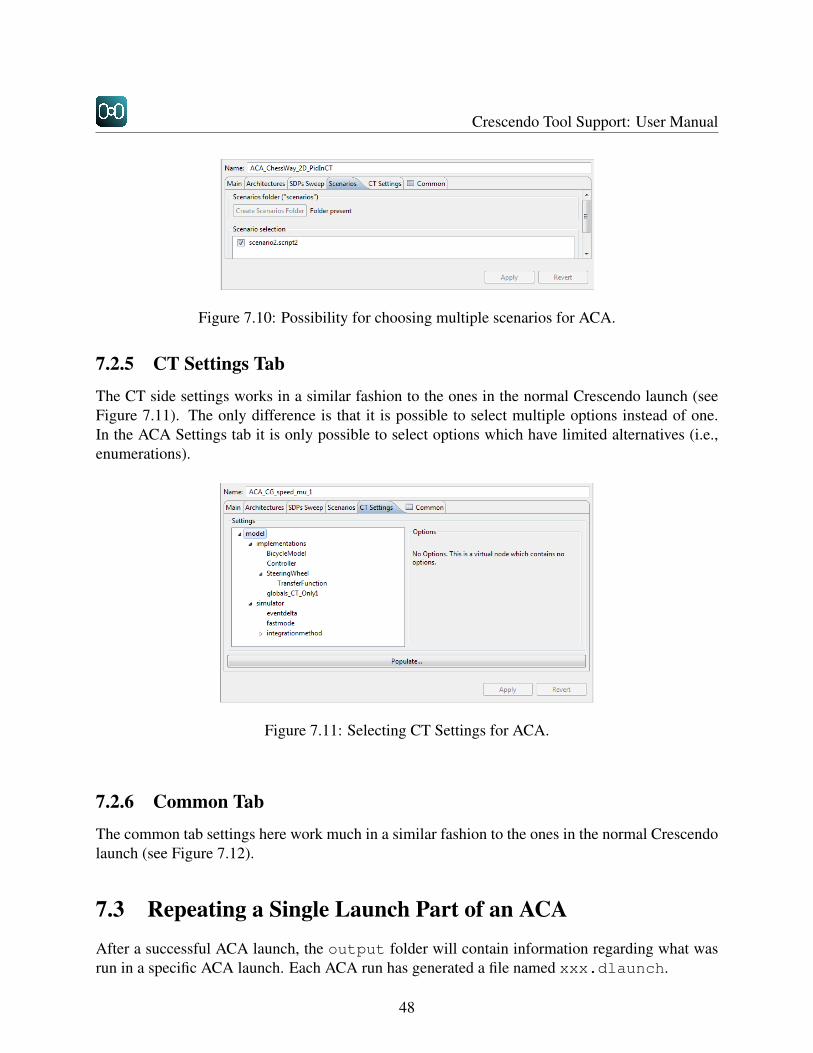
7.2.5 CT Settings Tab
The CT side settings works in a similar fashion to the ones in the normal Crescendo launch (seeFigure 7.11). The only difference is that it is possible to select multiple options instead of one.In the ACA Settings tab it is only possible to select options which have limited alternatives (i.e.,enumerations).
Figure 7.11: Selecting CT Settings for ACA.
7.2.6 Common Tab
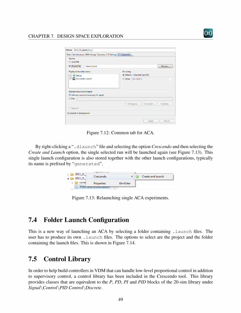
The common tab settings here work much in a similar fashion to the ones in the normal Crescendolaunch (see Figure 7.12).
7.3 Repeating a Single Launch Part of an ACAAfter a successful ACA launch, the output folder will contain information regarding what wasrun in a specific ACA launch. Each ACA run has generated a file named xxx.dlaunch.
48
CHAPTER 7. DESIGN SPACE EXPLORATION
Figure 7.12: Common tab for ACA.
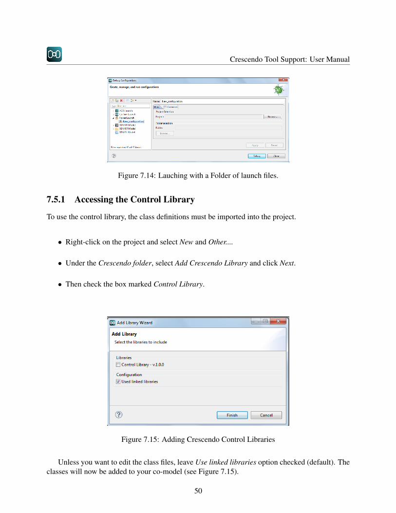
By right-clicking a “.dlaunch” file and selecting the option Crescendo and then selecting theCreate and Launch option, the single selected run will be launched again (see Figure 7.13). Thissingle launch configuration is also stored together with the other launch configurations, typicallyits name is prefixed by “generated”.
Figure 7.13: Relaunching single ACA experiments.
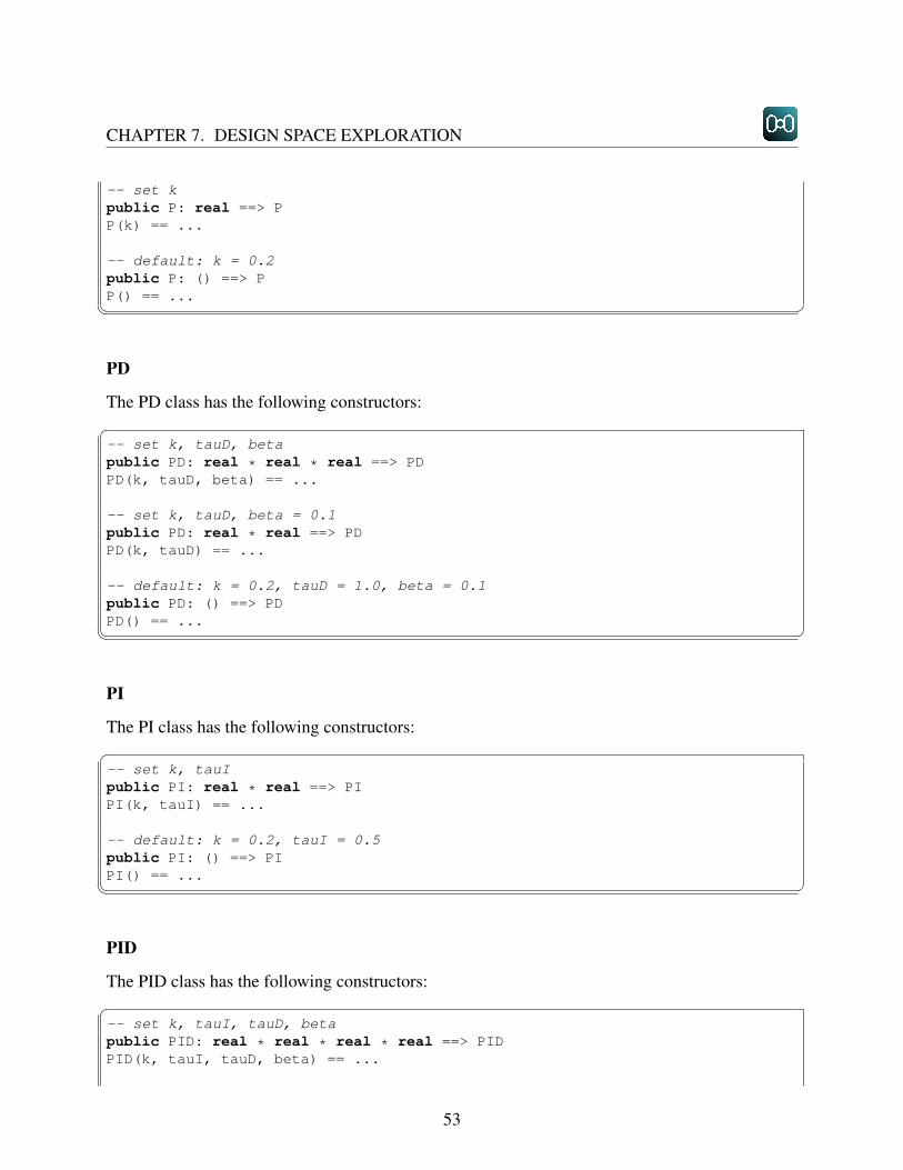
7.4 Folder Launch ConfigurationThis is a new way of launching an ACA by selecting a folder containing .launch files. Theuser has to produce its own .launch files. The options to select are the project and the foldercontaining the launch files. This is shown in Figure 7.14.
7.5 Control LibraryIn order to help build controllers in VDM that can handle low-level proportional control in additionto supervisory control, a control library has been included in the Crescendo tool. This libraryprovides classes that are equivalent to the P, PD, PI and PID blocks of the 20-sim library underSignal\Control\PID Control\Discrete.
49
Crescendo Tool Support: User Manual
Figure 7.14: Lauching with a Folder of launch files.
7.5.1 Accessing the Control Library
To use the control library, the class definitions must be imported into the project.
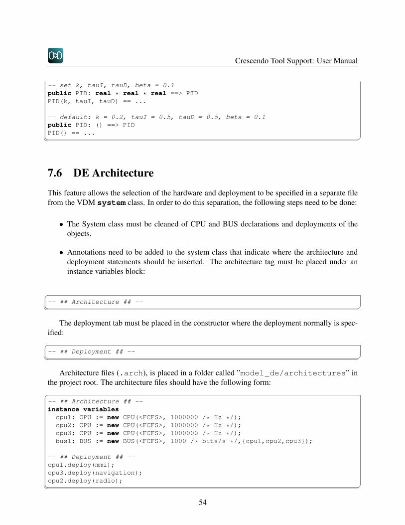
• Right-click on the project and select New and Other....
• Under the Crescendo folder, select Add Crescendo Library and click Next.
• Then check the box marked Control Library.
Figure 7.15: Adding Crescendo Control Libraries
Unless you want to edit the class files, leave Use linked libraries option checked (default). Theclasses will now be added to your co-model (see Figure 7.15).
50

CHAPTER 7. DESIGN SPACE EXPLORATION
7.5.2 Using the Control LibraryBasic Use
To use a class from the library, simply define a variable of the correct type, instantiate it with aconstructor, call “SetSampleTime” and then call “Output” in your control loop. All of thecontrol library classes have an operation called Output, which takes in an error and returns acontrol value, with the following form:�public Output: real ==> realOutput(err) == ...
class Controller
instance variables
-- controller objectprivate pid: PID;
-- setpointprivate SP: real;
-- shared variablesprivate MV: real;private out: real
operations-- constructor for Controllerpublic Controller: () ==> ControllerController() == (
pid := new PID(10, 1, 0.1);pid.SetSampleTime(SAMPLE_TIME)
);
-- control looppublic Step: () ==> ()Step() == (
dcl err: real := SP - MV;out := pid.Output(err)
);
-- 100Hz control loopvalues SAMPLE_TIME = 0.01;thread periodic(10E6, 0, 0, 0)(Step);
end Controller� �All of the classes have an operation called SetSampleTime, which takes a sample time in seconds:�
51

Crescendo Tool Support: User Manual
public SetSampleTime: real ==> ()SetSampleTime(s) ==� �
Unlike 20-sim, VDM does not have a sampletime keyword, so it is necessary to explicitly tellthe object what sample time to use in calculations. Therefore, for all control objects (except P) youmust call SetSampleTime before the ”Output” is used. This only needs to be done once andit is recommended that it is called immediately after the constructor. If this is not done, then theco-simulation will fail with a pre-condition violation the first time Output is called.
7.5.3 Advanced UseAll of the controller classes in the library are subclasses of a single class called “DTControl”(Discrete-Time control). This class contains the definitions for “SetSampleTime” and “Output”and enforces a consistent interface. It is possible to use the various controller classes without mak-ing reference to DTControl. However, if it is desirable to test different controllers, variables canbe defined as type DTControl, meaning that only the call to the constructor needs to be changedin order to use a different controller implementation. This is also useful if control objects arepassed to controllers. In the following example, the Controller class can accept any controlobject (P, PID etc.):�class Controller
instance variables
-- controller objectprivate ctrl: DTControl;
operations
-- constructor for Controllerpublic Controller: DTControl ==> ControllerController (c) == (
ctrl := c;ctrl.SetSampleTime(SAMPLE_TIME)
);
...� �7.5.4 ConstructorsP
The P class has the following constructors:�52
CHAPTER 7. DESIGN SPACE EXPLORATION
-- set kpublic P: real ==> PP(k) == ...
-- default: k = 0.2public P: () ==> PP() == ...� �PD
The PD class has the following constructors:�-- set k, tauD, betapublic PD: real * real * real ==> PDPD(k, tauD, beta) == ...
-- set k, tauD, beta = 0.1public PD: real * real ==> PDPD(k, tauD) == ...
-- default: k = 0.2, tauD = 1.0, beta = 0.1public PD: () ==> PDPD() == ...� �PI
The PI class has the following constructors:�-- set k, tauIpublic PI: real * real ==> PIPI(k, tauI) == ...
-- default: k = 0.2, tauI = 0.5public PI: () ==> PIPI() == ...� �PID
The PID class has the following constructors:�-- set k, tauI, tauD, betapublic PID: real * real * real * real ==> PIDPID(k, tauI, tauD, beta) == ...
53
Crescendo Tool Support: User Manual
-- set k, tauI, tauD, beta = 0.1public PID: real * real * real ==> PIDPID(k, tauI, tauD) == ...
-- default: k = 0.2, tauI = 0.5, tauD = 0.5, beta = 0.1public PID: () ==> PIDPID() == ...� �
7.6 DE Architecture
This feature allows the selection of the hardware and deployment to be specified in a separate filefrom the VDM system class. In order to do this separation, the following steps need to be done:
• The System class must be cleaned of CPU and BUS declarations and deployments of theobjects.
• Annotations need to be added to the system class that indicate where the architecture anddeployment statements should be inserted. The architecture tag must be placed under aninstance variables block:
�-- ## Architecture ## --� �
The deployment tab must be placed in the constructor where the deployment normally is spec-ified:�-- ## Deployment ## --� �
Architecture files (.arch), is placed in a folder called ”model de/architectures” inthe project root. The architecture files should have the following form:�-- ## Architecture ## --instance variables
cpu1: CPU := new CPU(<FCFS>, 1000000 /* Hz */);cpu2: CPU := new CPU(<FCFS>, 1000000 /* Hz */);cpu3: CPU := new CPU(<FCFS>, 1000000 /* Hz */);bus1: BUS := new BUS(<FCFS>, 1000 /* bits/s */,{cpu1,cpu2,cpu3});
-- ## Deployment ## --cpu1.deploy(mmi);cpu3.deploy(navigation);cpu2.deploy(radio);� �
54

CHAPTER 7. DESIGN SPACE EXPLORATION
When an architecture file like this is selected, the architecture and deployment declaration isinserted in the “right” place (under the tags in the system file), creating a “complete” system justbefore the co-simulation starts.
7.7 Events
Events can be triggered in the CT world. They will stop the simulation before the allowed timeslice is completed. The co-simulation engine will then allow the DE simulator to take action butonly until the point where the event has been raised. The events are used in the contract in order tosupport event-based triggering and not just time-triggered scheduling.
7.7.1 Simulation setup
Events in the contract
For events to be considered during a simulation the event must be defined in Section 5.3:
〈events〉 ::= ‘event’, 〈identifier〉, ‘;’
Events in the link file
Events must be connected to a public async operation in VDM. This is done by linking theevent name specified in the contract to the fully qualified operation name in VDM in the link file:
〈events〉 ::= ’event’, 〈identifier〉 = ’System’, ’.’, 〈identifier〉, (’.’, 〈identifier〉)+
An example of this could be:
event event1=System.eventHandler.event1;
where:
• “event1” is the event name from the contract.
• System is the system class.
• eventHandler is the class holding the public async operation to execute.
• “event1” (the last event1) is the async operation which to execute when the event occurs.
55

Crescendo Tool Support: User Manual
7.7.2 Events in CT
Events need to be marked in 20-sim using the keyword event, this marks the variable that itused as return value of the event function to be an event variable. The keywords eventdown andeventup are used as in standalone 20-sim models. Example:
variablesboolean minLevelReached (’event’);
equationsmaxLevelReached = eventup(levelIn-maxlevel);
7.7.3 Events in DE
The scheduler in VDM does not schedule events in the same way as for instance a microcontrollerwould do where the current executing job is suspended in favour of the interrupt routine. However,it is possible to get similar behaviour by creating and deploying an object to a CPU that contains thejob to run when an interrupt occurs and then call this from the async operation which is triggeredwhen event occurs. It is just important that no objects having a periodic threads are deployed to thesame CPU since this will delay the event by exactly one periodic loop. Events are linked to VDMthrough async operations and made accessable through the system class.�system Systeminstance variables
eventHandler: EventHandler;end System� �
The async operation must be specified in a class that is not deployed to a CPU. This makesthe evaluation instant. This means that the event operation it self does not take any time to run.�class EventHandler
operations
public async event1: () ==> ()event1()== skip;
end EventHandler� �Note about the VDM scheduler: The VDM scheduler uses priorities to select which thread
should run, each thread is then executed with a limited allowed number of expressions/statementsit can execute before another thread has to be schedulled and executed. The priority definedhow many expressions/statements a thread can execute at a time. A thread will always continue
56

CHAPTER 7. DESIGN SPACE EXPLORATION
executing until it is blocked or finished the allowed number of expressions/statements.
57

Crescendo Tool Support: User Manual
58
Chapter 8
Post-Analysis
8.1 OctaveGNU Octave is an open source and high-level interpreted language, primarily intended for nu-merical computations. It provides capabilities for the numerical solution of linear and non-linearproblems, and for performing other numerical experiments. It also provides extensive graphics ca-pabilities for data visualization and manipulation. Octave is normally used through its interactivecommand line interface, but it can also be used to write non-interactive (batch oriented) programs.The Octave language is quite similar to Matlab so that most programs are easily portable. See formore details http://www.gnu.org/software/octave/
The Octave project on Source Forge provides an easy installable Windows installer for Octave:http://octave.sourceforge.net/. Furthermore a Octave GUI is provided by http://www.gnu.org/software/octave/ which provides a workspace and editor that can beused to assist the user of Crescendo in creating custom scripts.
8.1.1 Octave use in CrescendoAfter each co-simulation run, an Octave script is automatically generated in the output dir. Thescript contains Octave code that reads the variable logs produced by both VDM and 20-sim duringthe simulation run.
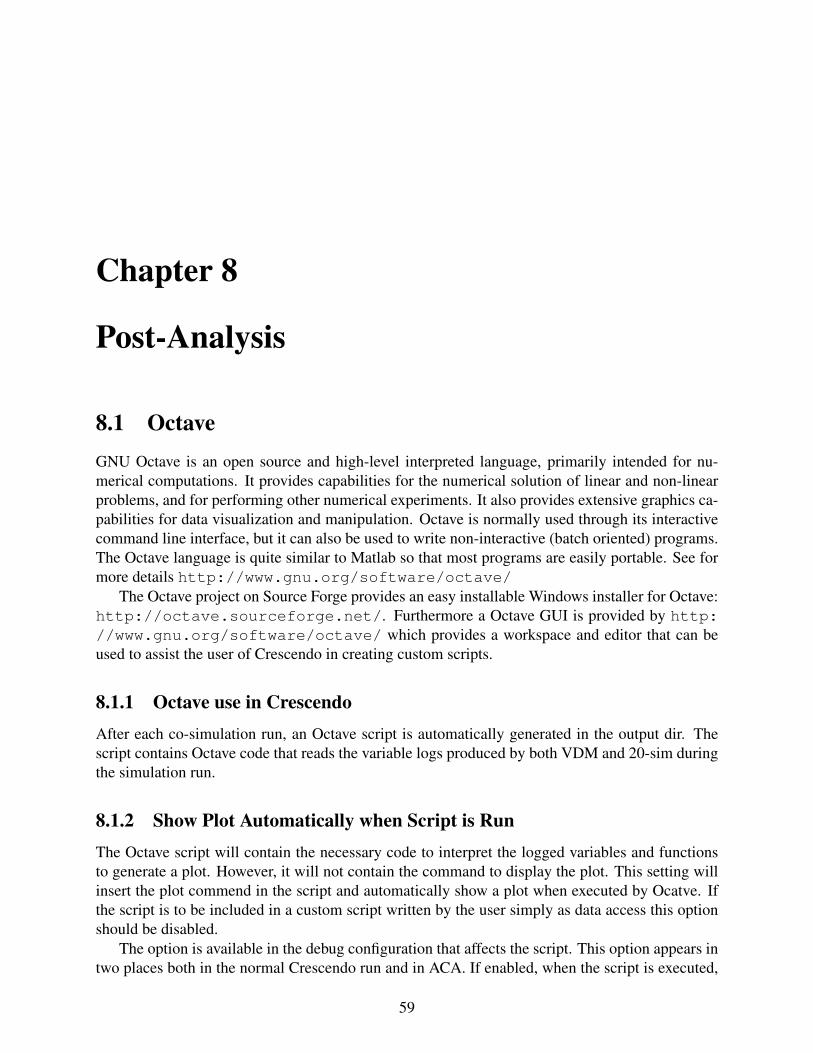
8.1.2 Show Plot Automatically when Script is RunThe Octave script will contain the necessary code to interpret the logged variables and functionsto generate a plot. However, it will not contain the command to display the plot. This setting willinsert the plot commend in the script and automatically show a plot when executed by Ocatve. Ifthe script is to be included in a custom script written by the user simply as data access this optionshould be disabled.
The option is available in the debug configuration that affects the script. This option appears intwo places both in the normal Crescendo run and in ACA. If enabled, when the script is executed,
59
Crescendo Tool Support: User Manual
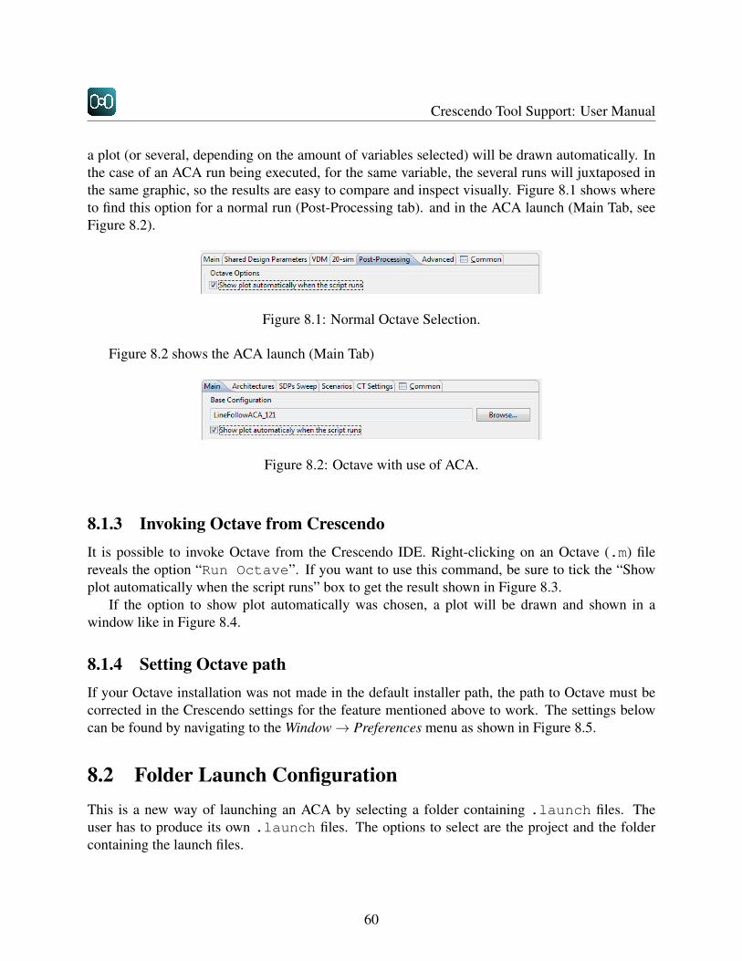
a plot (or several, depending on the amount of variables selected) will be drawn automatically. Inthe case of an ACA run being executed, for the same variable, the several runs will juxtaposed inthe same graphic, so the results are easy to compare and inspect visually. Figure 8.1 shows whereto find this option for a normal run (Post-Processing tab). and in the ACA launch (Main Tab, seeFigure 8.2).
Figure 8.1: Normal Octave Selection.
Figure 8.2 shows the ACA launch (Main Tab)
Figure 8.2: Octave with use of ACA.
8.1.3 Invoking Octave from CrescendoIt is possible to invoke Octave from the Crescendo IDE. Right-clicking on an Octave (.m) filereveals the option “Run Octave”. If you want to use this command, be sure to tick the “Showplot automatically when the script runs” box to get the result shown in Figure 8.3.
If the option to show plot automatically was chosen, a plot will be drawn and shown in awindow like in Figure 8.4.
8.1.4 Setting Octave pathIf your Octave installation was not made in the default installer path, the path to Octave must becorrected in the Crescendo settings for the feature mentioned above to work. The settings belowcan be found by navigating to the Window→ Preferences menu as shown in Figure 8.5.
8.2 Folder Launch ConfigurationThis is a new way of launching an ACA by selecting a folder containing .launch files. Theuser has to produce its own .launch files. The options to select are the project and the foldercontaining the launch files.
60

CHAPTER 8. POST-ANALYSIS
Figure 8.3: Octave in action.
Figure 8.4: Octave plotting in seperate window.
61

Crescendo Tool Support: User Manual
Figure 8.5: The Octave path settings in the Preferences dialog
Figure 8.6: Launching several configurations from a single directory
62
Bibliography
[ALRL04] Algirdas Avizienis, Jean-Claude Laprie, Brian Randell, and Carl Landwehr. BasicConcepts and Taxonomy of Dependable and Secure Computing. IEEE Transactionson Dependable and Secure Computing, 1:11–33, 2004.
[BJ78] D. Bjørner and C.B. Jones, editors. The Vienna Development Method: The Meta-Language, volume 61 of Lecture Notes in Computer Science. Springer-Verlag, 1978.
[BLV+10] J. F. Broenink, P. G. Larsen, M. Verhoef, C. Kleijn, D. Jovanovic, K. Pierce, andWouters F. Design Support and Tooling for Dependable Embedded Control Software.In Proceedings of Serene 2010 International Workshop on Software Engineering forResilient Systems, pages 77–82. ACM, April 2010.
[CCFJ99] Tim Clement, Ian Cottam, Peter Froome, and Claire Jones. The Development of aCommercial “Shrink-Wrapped Application” to Safety Integrity Level 2: the DUST-EXPERT Story. In Safecomp’99, Toulouse, France, September 1999. Springer Verlag.LNCS 1698, ISBN 3-540-66488-2.
[Con13] Controllab products. http://www.20sim.com/, January 2013. 20-Sim official website.
[FL98] John Fitzgerald and Peter Gorm Larsen. Modelling Systems – Practical Tools andTechniques in Software Development. Cambridge University Press, The EdinburghBuilding, Cambridge CB2 2RU, UK, 1998. ISBN 0-521-62348-0.
[FL09] John Fitzgerald and Peter Gorm Larsen. Modelling Systems – Practical Tools andTechniques in Software Development. Cambridge University Press, The EdinburghBuilding, Cambridge CB2 2RU, UK, Second edition, 2009. ISBN 0-521-62348-0.
[FLM+05] John Fitzgerald, Peter Gorm Larsen, Paul Mukherjee, Nico Plat, and Marcel Verhoef.Validated Designs for Object–oriented Systems. Springer, New York, 2005.
[FLV08] J. S. Fitzgerald, P. G. Larsen, and M. Verhoef. Vienna Development Method. WileyEncyclopedia of Computer Science and Engineering, 2008. edited by Benjamin Wah,John Wiley & Sons, Inc.
[FLV13] John Fitzgerald, Peter Gorm Larsen, and Marcel Verhoef, editors. Collaborative De-sign for Embedded Systems – Co-modelling and Co-simulation. Springer, 2013.
63

Crescendo Tool Support: User Manual
[IEE00] IEEE 100 The Authoritative Dictionary of IEEE Standards Terms Seventh Edition.IEEE Std 100-2000, 2000.
[ISO96] Information technology – Programming languages, their environments and systemsoftware interfaces – Vienna Development Method – Specification Language – Part 1:Base language, December 1996.
[Jon90] Cliff B. Jones. Systematic Software Development Using VDM. Prentice-Hall Interna-tional, Englewood Cliffs, New Jersey, second edition, 1990. ISBN 0-13-880733-7.
[Kle09] C. Kleijn. 20-sim 4.1 Reference Manual. Controllab Products B.V., Enschede, Firstedition, 2009. ISBN 978-90-79499-05-2.
[KN09] T. Kurita and Y. Nakatsugawa. The Application of VDM++ to the Development ofFirmware for a Smart Card IC Chip. Intl. Journal of Software and Informatics, 3(2-3):343–355, October 2009.
[LH96] Peter Gorm Larsen and Bo Stig Hansen. Semantics for underdetermined expressions.Formal Aspects of Computing, 8(1):47–66, January 1996.
[LLB+13] Peter Gorm Larsen, Kenneth Lausdahl, Nick Battle, John Fitzgerald, Sune Wolff, andShin Sahara. VDM-10 Language Manual. Technical Report TR-001, The OvertureInitiative, www.overturetool.org, April 2013.
[LLJ+13] Peter Gorm Larsen, Kenneth Lausdahl, Peter Jørgensen, Joey Coleman, Sune Wolff,and Nick Battle. Overture VDM-10 Tool Support: User Guide. Technical ReportTR-2010-02, The Overture Initiative, www.overturetool.org, April 2013.
[MBD+00] Paul Mukherjee, Fabien Bousquet, Jerome Delabre, Stephen Paynter, and Peter GormLarsen. Exploring Timing Properties Using VDM++ on an Industrial Application. InJ.C. Bicarregui and J.S. Fitzgerald, editors, Proceedings of the Second VDM Work-shop, September 2000. Available at www.vdmportal.org.
[Rob04] Stewart Robinson. Simulation: The Practice of Model Development and Use. JohnWiley & Sons, 2004.
[VLH06] Marcel Verhoef, Peter Gorm Larsen, and Jozef Hooman. Modeling and ValidatingDistributed Embedded Real-Time Systems with VDM++. In Jayadev Misra, TobiasNipkow, and Emil Sekerinski, editors, FM 2006: Formal Methods, Lecture Notes inComputer Science 4085, pages 147–162. Springer-Verlag, 2006.
64
Appendix A
Glossary
As might be expected in interdisciplinary projects, terms and concepts that are well known in onediscipline may be unknown or understood quite differently in another. This appendix thereforecontains common descriptions of core concepts that are used with the Crescendo technology.
abstract class (in object oriented programming) a class where one or more methods are definedabstractly using the text is subclass responsibility as their body.
actuator a component that produces a physical output in response to a signal [IEE00].
aggregate (in object oriented programming) the act of bringing together several objects into asingle whole.
automated co-model analysis tool support for the selection of a single design from a set of designalternatives (including definition of scenarios, execution of co-simulations, and visualisationand analysis of co-simulation results).
automated co-model execution as automated co-model analysis except that is does not performany analysis of the test results produced by the simulations
bond (in bond graphs) a directed point-to-point connection between power ports on submodels.Represents the sharing of both flow and effort by those ports.
bond graph a domain independent idealised physical model based on the representing energy andits exchange between submodels.
causality (in bond graphs) dictates which variable of a power port is the input (cause) for sub-model’s equations and which is the output (effect).
class (in object oriented programming) the definition of the data field and methods an object ofthat class will contain.
65

Crescendo Tool Support: User Manual
code generation the process of implementing a system controller by automatically translating amodel into a representation (in some programming language) which can then be executed onthe real hardware of the system.
co-model a model comprising two constituent models (a DE submodel and a CT submodel) anda contract describing the communication between them.
consistency a co-model is consistent if the constituent models are both syntactically and semanti-cally consistent.
constituent model one of the two submodels in a co-model.
continuous-time simulation a form of simulation where “the state of the system changes contin-uously through time” [Rob04, p. 15].
contract a description of the communication between the constituent models of a co-model, givenin terms of shared design parameters, shared variables, and common events.
controlled variable a variable that a controller changes in order to perform control actions.
controller the part of the system that controls the plant.
controller architecture the allocation of software processes to CPUs and the configuration ofthose CPUs over a communications infrastructure.
co-sim launch the type of debug configuration used in the Crescendo tool to define and launch asingle scenario.
co-simulation baseline the set of elements (co-model, scenario, test results etc.) required to re-produce a specific co-simulation.
co-simulation engine a program that supervises a co-simulation.
co-simulation the simulation of a co-model.
cost function a function which calculates the “cost” of a design.
debug config (Eclipse term) the place in Eclipse where a simulation scenario is defined.
design alternatives where two or more co-models represent different possible solutions to thesame problem.
design parameter a property of a model that affects its behaviour, but which remains constantduring a given simulation.
design space exploration the (iterative) process of constructing co-models, performing co-simulationsand evaluating the results in order to select co-models for the next iteration.
66

APPENDIX A. GLOSSARY
design step a co-model which is considered to be a significant evolution of a previous co-model.
discrete-event simulation a form of simulation where “only the points in time at which the stateof the system changes are represented” [Rob04, p. 15].
disturbance a stimulus that tends to deflect the plant from desired behaviour.
edges (in bond graphs) see bond.
effort (in bond graphs) one of the variables exposed by a power port. Represents physical conceptssuch as electrical voltage, mechanical force or hydraulic pressure.
environment everything that is outside of a given system.
error part of the system state that may lead to a failure [ALRL04].
event an action that is initiated in one constituent model of a co-model, which leads to an actionin the other constituent model.
executable model a model that can be simulated.
failure a system’s delivered service deviates from specification [ALRL04].
fault injection the act of triggering faulty behaviour during simulation.
fault modelling the act of extending a model to encompass faulty behaviours.
fault the adjudged or hypothesized cause of an error [ALRL04].
fault behaviour a model of a component’s behaviour when a fault has been triggered and emergesas a failure to adhere to the component’s specification.
fault-like phenomena any behaviour that can be modelled like a fault (e.g. disturbance).
flow (in bond graphs) one of the variables exposed by a power port. Represents physical conceptssuch as electrical current, mechanical velocity, fluid flow.
ideal behaviour a model of a component that does not account for disturbances.
inheritance (in object oriented programming) the mechanism by which a subclass contains allpublic and protected data fields and methods of its superclass.
input a signal provided to a model.
interface (in object oriented programming) a class which defines the signatures of but no bodiesfor any of its methods. Should not be instantiated.
junction (in bond graphs) a point in a bond graph where the sum of flow (1-junction) or effort(0-junction) of all bonds to that point is zero.
67

Crescendo Tool Support: User Manual
log data written to a file during a simulation.
metadata information that is associated with, and gives information about, a piece of data.
model base the collection of artefacts gathered during a development (including various modelsand co-models; scenarios and test results; and documentation).
model management the activity of organizing co-models within a model base.
model structuring the activity of organizing elements within a model.
model synthesis see code generation.
model a more or less abstract representation of a system or component of interest.
modelling the activity of creating models.
modularisation construction of self-contained units (modules) that can be combined to formlarger models.
monitored variable a variable that a controller observes in order to inform control actions.
object (in object oriented programming) an instantiation of a class, contains data fields and meth-ods.
objective function see cost function.
ontology a structure that defines the relationships between concepts.
operation (in object oriented programming) defines an operation that an object may perform onsome data. Operations may be private, public or protected.
output the states of a model as observed during (and after) simulation.
non-normative behaviour behaviour that is judged to deviate from specification.
physical concept (in bond graphs) a class of component or phenomena that could exist or beobserved in the real world, e.g. an electrical resistor or mechanical friction.
plant the part of the system which is to be controlled [IEE00].
power port (in bond graphs) the port type connected in a bond graph. Contains two variables,effort and flow. A power port exchanges energy with its connected models.
private (in object oriented programming, VDM) the method or data field may only be accessedfrom within the containing class.
protected (in object oriented programming, VDM) the method or data field may only be accessedby its containing class or any of its subclasses.
68

APPENDIX A. GLOSSARY
public (in object oriented programming, VDM) the method or data field may be accessed by anyother class.
ranking function a function that assigns a value to a design based on its ability to meet require-ments defined by the engineer.
realistic behaviour a model of a component which includes disturbances defined by the toler-ances associated with that component.
repository a shared store of data or files.
response a change in the state of a system as a consequence of a stimulus.
revision control the activity of managing changes (revisions) to computer data or files.
scenario test of a co-model.
signal domain where models share a single value or array at each port and where those ports areuni-directional, unlike bond graphs where the ports are bi-directional.
sensor a component whose input is a physical phenomenon and whose output is a quantitativemeasure of the phenomenon.
shared design parameter a design parameter that appears in both constituent models of a co-model.
shared variable a variable that appears in and can be accessed from both constituent models of aco-model.
simulation symbolic execution of a model.
semantically consistent the state when the constituent models of a co-model agree on the seman-tics of the varaibles, parameters and events they share. The nature of these semantics is notyet described.
static analysis a method for checking some property of a model without executing that model.
state event an event triggered by a change within a model.
stimulus a phenomenon that effects a change in the state of a system.
subclass (in object oriented programming) a class that is defined as extending another class. Theother class becomes its superclass. The subclass inherits all non private data fields andmethods.
submodel a distinct part of a larger model.
superclass (in object oriented programming) the class from which a subclass is defined.
69

Crescendo Tool Support: User Manual
syntactically consistent the state when the constituent models of a co-model agree on the identi-ties and data types of all shared variables, parameters and events.
system boundary the common frontier between a system and its environment.
system under test (SUT) the part of a model that represents the system we wish to build, as op-posed to parts of the model which are not part of this system.
system an entity that interacts with other entities, including hardware, software, humans and thephysical world [ALRL04].
tag to associate metadata with a piece of data.
test result a record of the output from a simulation of a model (see also log).
time event an expected event that occurs at a predetermined time.
variable part of a model that may change during a given simulation.
vertices (in bond graphs) the joining points of bonds. May be manifested as either a junction or asubmodel.
70