Crash Analysis of Auto-body Structures Considering the Strain-Rate...
6
1 Seoul 2000 FISITA World Automotive Congress 2000G292 June 12-15, 2000, Seoul, Korea Crash Analysis of Auto-body Structures Considering the Strain-Rate Hardening Effect Woo Jong Kang and Hoon Huh * Department of Mechanical Engineering, Korea Advanced Institute of Science and Technology 373-1 Kusong-dong, Yusong-gu, Taejon, 305-701, Korea The crashworthiness of vehicles with finite element methods depends on the geometry modeling and the material properties. The vehicle body structures are generally composed of various members such as frames, stamped panels and deep-drawn parts from sheet metals. In order to ensure the impact characteristics of auto-body structures, the dynamic behavior of sheet metals must be examined to provide the appropriate constitutive relation. In this paper, high strain-rate tensile tests have been carried out with a tension type split Hopkinson bar apparatus specially designed for sheet metals. Experimental results from both static and dynamic tests with the tension split Hopkinson bar apparatus are interpolated to construct the Johnson-Cook and a modified Johnson-Cook equation as the constitutive relation, that should be applied to simulation of the dynamic behavior of auto-body structures. Simulation of auto-body structures has been carried out with an elasto-plastic finite element method with explicit time integration. The stress integration scheme with the plastic predictor elastic corrector method is adopted in order to accurately keep track of the stress–strain relation for the rate-dependent model accurately. The crashworthiness of the structure with quasi-static constitutive relation is compared to the one with the rate-dependent constitutive model. Numerical simulation has been carried out for frontal frames and a hood of an automobile. Deformed shapes and the impact energy absorption of the structure are investigated with the variation of the strain rate. Keywords: Split Hopkinson bar, Crashworthiness, Strain rate hardening INTRODUCTION The crashworthiness of auto-body structures is one of the important issues in the automotive industry. The automotive industry has made an effort to develop light- weight auto-body structures for the purpose of increasing the fuel efficiency and satisfying the emission gas regulation of vehicles. Since the weight reduction of an auto-body should not sacrifice the safety, the crash analysis has to be accurately conducted in order to efficiently reduce the auto- body weight. The vehicle body structures are generally constructed by sheet metals of deep-drawn parts. Since the strength of steel sheets depends on the rate of deformation, the dynamic behavior of sheet metals is a key to investigate the impact characteristics of the structure. As the dynamic behavior of a material is different from the static one due to the inertia effect and the propagation of stress waves, an adequate experimental technique has to be developed to obtain the dynamic response for the corresponding level of the strain rate. A high strain-rate testing apparatus was devised by Kolsky[1] in 1949, which is known as the split Hopkinson pressure bar[2]. The stress strain curves for the high strain-rate ranged from 1000 to 10000/sec can be acquired from the stress waves propagating through the incident and the transmitted bar in the apparatus. The split Hopkinson pressure bar apparatus can be modified for high strain-rate tensile tests, although there are some difficulties in design of grips and specimens as well as estimation of errors [3, 4]. Various types of constitutive relations have been proposed to describe the dynamic behavior of materials. Johnson and Cook [5] suggested a constitutive model and determined five material constants in the constitutive relation for materials subjected to large strains, high strain-rates and high temperatures. Zhao and Gary [6] performed high strain- rate compression tests of sheet metals with a compression split Hopkinson bar apparatus. Kang et al. [7] acquired the high strain-rate tensile properties of sheet metals with a tension split Hopkinson bar apparatus and proposed a modified Johnson-Cook model for sheet metals. Results showed that the model has to be described with a quadratic function for the strain-rate term in order to fit experimental results for sheet metal. In this paper, numerical simulations are carried out with an elasto-plastic explicit finite element method. A shell element formulation has been derived for the crashworthiness of auto-body structures incorporating with a contact algorithm. The present algorithm adopts the plastic predictor elastic corrector (PPEC) scheme[8] in stress integration in order to accurately keep track of the stress– strain relation for the rate-dependent model. The constitutive model obtained from dynamic experiments is imposed on the * Corresponding author. e-mail:[email protected]
Transcript of Crash Analysis of Auto-body Structures Considering the Strain-Rate...

1
Seoul 2000 FISITA World Automotive Congress 2000G292 June 12-15, 2000, Seoul, Korea
Crash Analysis of Auto-body Structures Considering the Strain-Rate Hardening Effect
Woo Jong Kang and Hoon Huh*
Department of Mechanical Engineering, Korea Advanced Institute of Science and Technology
373-1 Kusong-dong, Yusong-gu, Taejon, 305-701, Korea
The crashworthiness of vehicles with finite element methods depends on the geometry modeling and the material properties. The vehicle body structures are generally composed of various members such as frames, stamped panels and deep-drawn parts from sheet metals. In order to ensure the impact characteristics of auto-body structures, the dynamic behavior of sheet metals must be examined to provide the appropriate constitutive relation. In this paper, high strain-rate tensile tests have been carried out with a tension type split Hopkinson bar apparatus specially designed for sheet metals. Experimental results from both static and dynamic tests with the tension split Hopkinson bar apparatus are interpolated to construct the Johnson-Cook and a modified Johnson-Cook equation as the constitutive relation, that should be applied to simulation of the dynamic behavior of auto-body structures. Simulation of auto-body structures has been carried out with an elasto-plastic finite element method with explicit time integration. The stress integration scheme with the plastic predictor elastic corrector method is adopted in order to accurately keep track of the stress–strain relation for the rate-dependent model accurately. The crashworthiness of the structure with quasi-static constitutive relation is compared to the one with the rate-dependent constitutive model. Numerical simulation has been carried out for frontal frames and a hood of an automobile. Deformed shapes and the impact energy absorption of the structure are investigated with the variation of the strain rate.
Keywords: Split Hopkinson bar, Crashworthiness, Strain rate hardening
INTRODUCTION
The crashworthiness of auto-body structures is one of the important issues in the automotive industry. The automotive industry has made an effort to develop light-weight auto-body structures for the purpose of increasing the fuel efficiency and satisfying the emission gas regulation of vehicles. Since the weight reduction of an auto-body should not sacrifice the safety, the crash analysis has to be accurately conducted in order to efficiently reduce the auto-body weight. The vehicle body structures are generally constructed by sheet metals of deep-drawn parts. Since the strength of steel sheets depends on the rate of deformation, the dynamic behavior of sheet metals is a key to investigate the impact characteristics of the structure.
As the dynamic behavior of a material is different from the static one due to the inertia effect and the propagation of stress waves, an adequate experimental technique has to be developed to obtain the dynamic response for the corresponding level of the strain rate. A high strain-rate testing apparatus was devised by Kolsky[1] in 1949, which is known as the split Hopkinson pressure bar[2]. The stress strain curves for the high strain-rate ranged from 1000 to 10000/sec can be acquired from the
stress waves propagating through the incident and the transmitted bar in the apparatus. The split Hopkinson pressure bar apparatus can be modified for high strain-rate tensile tests, although there are some difficulties in design of grips and specimens as well as estimation of errors [3, 4].
Various types of constitutive relations have been proposed to describe the dynamic behavior of materials. Johnson and Cook [5] suggested a constitutive model and determined five material constants in the constitutive relation for materials subjected to large strains, high strain-rates and high temperatures. Zhao and Gary [6] performed high strain-rate compression tests of sheet metals with a compression split Hopkinson bar apparatus. Kang et al. [7] acquired the high strain-rate tensile properties of sheet metals with a tension split Hopkinson bar apparatus and proposed a modified Johnson-Cook model for sheet metals. Results showed that the model has to be described with a quadratic function for the strain-rate term in order to fit experimental results for sheet metal.
In this paper, numerical simulations are carried out with an elasto-plastic explicit finite element method. A shell element formulation has been derived for the crashworthiness of auto-body structures incorporating with a contact algorithm. The present algorithm adopts the plastic predictor elastic corrector (PPEC) scheme[8] in stress integration in order to accurately keep track of the stress–strain relation for the rate-dependent model. The constitutive model obtained from dynamic experiments is imposed on the
* Corresponding author. e-mail:[email protected]

2
analysis for the dynamic response of auto-body structures instead of the static model that has been generally adopted in dynamic simulation. The crash analysis is performed for auto-body structures such as frontal frames of an automobile and a hood. The finite element model of an automobile is adopted from the web site of NHTSA (National Highway Traffic Safety Administration). Simulation results provide the deformed shape and the deformation energy in order to predict and evaluate the crashworthiness of a car.
FINITE ELEMENT FORMULATION
For an updated Lagrangian formulation, the configuration tΩ at time t is taken as the reference state so that all static and kinematic variables are referred to this configuration. An incremental form of the principle of virtual work can be expressed as Eq(1) with an increment of t∆ which is small enough that the first Piola-Kirchhoff is nearly the same as the Cauchy stress[9].
ijitt
ijitt
iitt
i
itt
i
ududutdub
duu
ttf
t
t
∀Ω−Γ+Ω=
Ω
∫∫∫∫
Ω
∆+
Γ
∆+
Ω
∆+
Ω
∆+
,,σρρ
ρ (1)
di onuthatsuch Γ= 0 where iu is an arbitrary virtual displacement vector, ijσ is the Cauchy stress tensor defined in the configuration , ρ is
the mass density, ib is the body force vector. The above equation is then approximated into finite dimension with the use of the shell element by the degenerated continuum approach.
The stress and the rate of deformation are expressed in the co-rotational coordinates at the centroid of an element. The local Cartesian coordinate system is defined element-wise by the local Cartesian unit vectors 1e , 2e , 3e . The superscript ^ denotes the local Cartesian coordinate system while 1e , 2e , 3e are the global Cartesian unit base vectors. From the Mindlin-Reissner formulation that admits the transverse shear but assumes that the pseudo-normal remains straight, the velocity interpolation for the element in the co-rotational components can be written as follows:
+−+= )ˆˆ(
2ˆ),(),,(ˆ 211112 IIiIIi
dvNv ωδωδηξςηξ (2)
where d is the thickness, ),( ηξIN are the isoparametric shape function and δ is the Kronecker delta. The rate-of-deformation tensor in the local Cartesian coordinate system is written as follows:
)ˆˆ
ˆˆ
(21ˆ
i
j
j
iij x
vxvd
∂∂
+∂∂= (3)
The poor behavior of warped elements is corrected by superposing additional terms into the strain-displacement equations. The additional terms couple the curvature to the
translation within an element[10, 11]. A reduced integration technique is employed to avoid locking phenomena and efficiently perform time integration with an explicit scheme. The physical stabilization scheme[11] is used to control the zero-energy mode that results from the reduced integration rule. To solve the governing equation, the internal forces and moments calculated in the local coordinate system are to be expressed in the global Cartesian coordinate system with the transformation matrix R~ . I
tI fRf ˆ~= (4)
where If is the global nodal force vector calculated from the principle of virtual power. The transformation matrix is expressed as follows:
=
××
××
3232
3333
00~R
RR (5)
where jiij eeR ⋅= ˆ (6) The formulation (1) can be approximated by spatial discretization with shell elements as a matrix equation as follows: tt
itt
itt
itt
ii HFPuM ∆+∆+∆+∆+ +−= (7) where iM is the lumped mass matrix, tt
iP ∆+ is the external force vector at time tt ∆+ , tt
iF ∆+ is the internal force vector at time tt ∆+ and tt
iH ∆+ is the hourglass resistance vector. The explicit finite element analysis solves a set of
hyperbolic wave equations in the zone of influence of the wave front without coupling large number of equations. Explicit integration of the governing equation in the time domain is performed with the central difference scheme. The velocity and displacement vectors at the current time step are calculated as follows:
ti
tt
i
tt
i utuu ∆+=∆−∆+22 (8a)
2tt
iti
tti utuu
∆+∆+ ∆+= (8b) The critical time step of the central difference integration is calculated from the Courant stability condition that is the period of the maximum natural frequency of the system.
The velocity gradient for each shell element is calculated with an explicit time integration scheme for dynamic elasto-plastic finite element analysis. A simple explicit algorithm that estimates the subsequent yield surface in each time increment without iteration was proposed by Nemat-Nasser and Chung[8]. Since the incremental deformation for a designated time step is assumed to be plastic at first and then corrected along an elastic integration path, this method is called the plastic-predictor elastic-

3
Transmitted bar Incident bar
Anvil
Striker tube
Specimen
gas gun S1 S2
Oscilloscope
corrector (PPEC). The method is stable and accurate regardless of the time or strain increment and accurately calculates the stress in large plastic deformation state with much smaller time steps than that of the radial return method. For the reason, PPEC is adopted in the present shell formulation.
EXPERIMENT AND CONSTITUTIVE RELATIONS OF SHEET METALS
A tensile split Hopkinson bar apparatus is used to
acquire high strain-rate behavior of steel sheets as shown in Fig. 1. The signals from the strain gages are monitored and acquired by an oscilloscope. The reflected pulse measured by an oscilloscope is used to calculate the strain rate in a specimen with Eq(9). This strain rate is integrated with respect to time in order to obtain the strain in a specimen as represented by Eq(10). The transmitted pulse is used to calculate the stress in a specimen with Eq(11).
)(2)( tLCt R
s
e εε = (9)
ττεε ∫=t
dt0
)()( (10)
)()( 0 tAAEt T
s
εσ = (11)
where eC is the speed of an elastic wave in a bar and sL is the effective gage length of a specimen. The subscript R and T indicate the reflected and the transmitted pulse respectively. 0A and sA are the area of a bar and a specimen respectively. E is Young’s modulus of a bar. Quasi-static tensile tests were carried out at the strain rate of 0.003/sec and 1/sec. The test result at the strain rate of 1/sec was chosen as the reference stress strain curve to determine the constants in the Johnson-Cook constitutive relation. The strain rate acquired in the present experiments was ranged from 0.003/sec to 10000/sec. Experimental results are represented in Fig. 2 and interpolated to construct constitutive relations of sheet metals. The conventional Johnson-Cook model is written as Eq(12).
)1)(ln1)(( *mn TCBA −++= εεσ (12) where T* is the homologous temperature represented by Eq(13).
roommelt
room
TTTTT−
−=* (13)
where T is the temperature of the specimen, and meltT is the melting temperature of the specimen.
Figure 1 – Schematic description of the tension split Hopkinson bar apparatus
Figure 2 – Stress strain curves of 60TRIP from experiments The first term in the equation is the strain hardening term, the second is the strain-rate hardening term, and the third is the thermal softening term. The constant in the second term is determined by the initial yield stresses with respect to the strain rates as plotted in Fig. 3 with a semi-log scale.
In the Johnson-Cook relation, the stresses at the strain rate of 1/sec and a higher level are linearly interpolated as shown in the figure with a dashed line. Experimental results show that the linear interpolation is not adequate to sheet metals. For better description of the materials behavior, the experimental data is interpolated using a quadratic curve as shown in Eq(14).
)1]()(lnln1)[( *2
21mn TCCBA −+++= εεεσ (14)
The quadratic interpolation of the strain-rate hardening effect was proved to reduce the deviation from the experimental data as shown in Fig. 3 with a solid line. The constitutive relation presented is obtained from the adiabatic condition, which would well describe the dynamic behavior of sheet metals at the high strain rate. There will be, however, discrepancy between the curves and the metal
0.00 0.05 0.10 0.15 0.20 0.25 0.300
100
200
300
400
500
600
700
800
900
1000
1/sec0.003/sec
1650/sec3000/sec5000/sec
11000/sec
Strain
Stre
ss [M
Pa]
60TRIP

4
behavior at the moderate or low strain rate where the condition is between the adiabatic and isothermal ones. The material properties in the constitutive relation are shown in Table 1. Figure 3 – Initial yield stress of 60TRIP with respect to the strain rate Table 1– Constants in the original and modified Johnson-Cook constitutive relation for sheet metals.
CRASH ANALYSIS OF AUTO-BODY STRUCTURES
The crashworthiness of vehicles with finite element methods depends on the geometry modeling and the material properties. Although there is a large amount of information that is not clearly defined as the input for finite element codes, the finite element method is the most widely used numerical tool for the crashworthiness of auto-body structures. The automobile is composed of various materials such as rubbers, composites and metals. Since the behavior of the materials is quite nonlinear, experimental techniques and the mathematical definition of the material behavior are quite complicated. The behavior of materials has to be verified to guarantee simulation results. One of the important parameters that have to be verified is the strain-rate effect of materials. In this paper, the rate-dependent constitutive relation of sheet metals is determined and used in numerical simulations. The crashworthiness of auto-body structures with the quasi-static constitutive relation is compared to the one with rate-dependent constitutive model such as the Johnson-Cook model. The vehicle model that is used in simulation is Ford Taurus whose finite element model is adopted from NHTSA web site. Auto-body structures such
as frontal frames and a hood are separated from the full Taurus model and used in numerical simulation. The vehicle crashworthiness is greatly affected by side members and s-rails that are the energy absorbing structures with the axial and bending collapse mode. These structures are designed to effectively dissipate the vehicle kinetic energy in terms of plastic deformation in favor of the safety of passengers. Simulation results provide the deformed shape and the deformation energy in order to predict and evaluate the crashworthiness of a car. During the crash incident, the structure is subjected to the high impact load into large deformation and rotation with contact among various components. The deformation initially involves stress wave transition. Once the stress exceeds the yield strength of the material or its critical buckling load, localized deformation occurs during a few wave transits in the structure. This is followed by the inertial effect that dominates the subsequent transient response.
A finite element model of the frontal frame structure of Taurus is shown in Fig. 4 with its boundary and loading conditions. Simulation is conducted by using the Johnson-Cook model and the quasi-static model for SPCEN in order to compare the strain-rate effect of the two. SPCEN is one of the sheet steels that have been commonly used in auto body structures. The thickness of sheet metal is considered to be 1.2mm for all components. The initial impact velocity of a rigid wall is 48km/h, and the mass of the wall is 500kg. Deformed shapes from the finite element analysis are shown in Fig. 5. The time–deformation energy and the time–displacement curves are shown in Fig. 6. It is noted that the deformation is concentrated on frontal frames and s-rails while the passenger room is undeformed. Although the amount of deformation that is calculated with the quasi-static model is larger than that with the dynamic model, the deformation modes of the two are the same due to the controlled weak parts in the structures. Figure 4 – Finite element model of the frontal frame of an automobile
A (MPa)
B (MPa) n C C1 C2 m
SPCEN 208 350 0.48 0.140 0.080 0.007 0.31
60TRIP 432 800 0.59 0.075 0.030 0.012 0.55
60C 463 800 0.63 0.036 0.037 0.004 0.63
1 E -3 0 .0 1 0 .1 1 1 0 1 0 0 1 0 0 0 1 0 0 0 00
1 0 0
2 0 0
3 0 0
4 0 0
5 0 0
6 0 0
Initi
al y
ield
str
ess
[M
Pa
]
S tra in ra te [/s e c ]R
igid Wall
V=48km/h
fixed

5
(a) (b) (c)
(d) (e) Figure 5 – Initial and deformed shapes of frontal frames of an automobile: (a) initial shape; (b) displacement of 100 mm with the J-C model; (c) displacement of 100 mm with the quasi-static model; (d) displacement of 300 mm with the J-C model; (e) displacement of 300mm with the quasi-static model
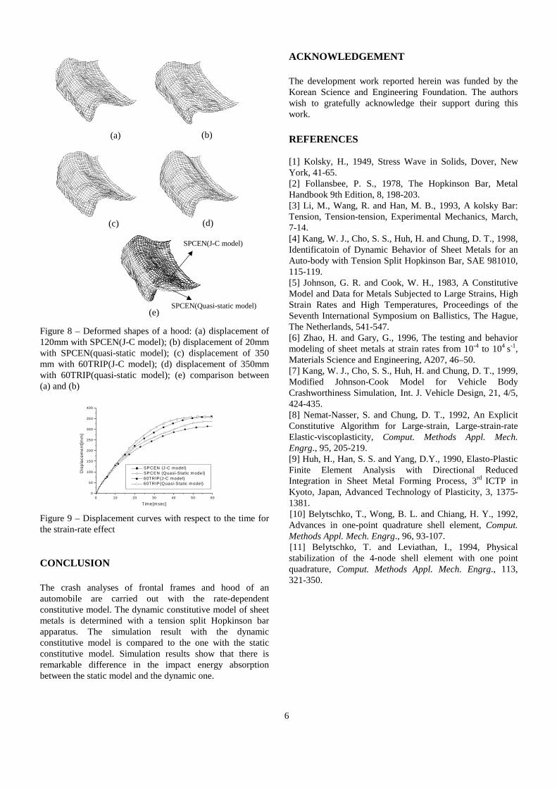
The hood of an automobile is composed of an inner and an outer panel, which contact each other as deformation progresses. The initial shape and the boundary condition of the hood are shown in Fig. 7. In order to effectively absorb the impact energy, structural weak parts are formed in the inner panel as shown in Fig. 7. The sheet metals used in crash analysis of the hood are SPCEN and 60TRIP. 60TRIP is one of the high strength steels made from the transformation-induced-plasticity process for the purpose of weight reduction. The initial impact velocity of a rigid wall is 48km/h, and the mass of the wall is 500kg. Although the impact responses depends on the boundary conditions and the type of a barrier, the simplified fixed boundary condition is used to evaluate the rate dependency of a material. Deformed shapes are presented in Fig. 8 with respect to the constitutive model. Deformed shapes become quite different depending on the material model as shown in Fig. 8 (e). The displacement at the front end of the hood is shown in Fig. 9.
(a) (b) Figure 6 – Deformation energy and displacement with respect to the time for the strain-rate effect: (a) Time–deformation energy curve; (b) Time–displacement curve
(a) (b) Figure 7 – Finite element mesh of a hood and the boundary condition: (a) outer view; (b) inner view When the strain-rate hardening effect is considered with the dynamic constitutive relation, the final displacement becomes relatively small compared to the one with the quasi-static model. It is noted from the result that the rate-dependent crash analysis must be carried out with its dynamic material properties identified for the purpose of the light-weight design of an auto-body with high strength steel.
0 5 10 15 20 25 300
5
10
15
20
25
30
35
40
Inte
rnal
ene
rgy[
kJ]
Time[msec]
J-C model Quasi-static model
0 5 10 15 20 25 300
50
100
150
200
250
300
350
Dis
plac
emen
t[mm
]
Time[msec]
J-C model Quasi-static model
fixed
6
Figure 8 – Deformed shapes of a hood: (a) displacement of 120mm with SPCEN(J-C model); (b) displacement of 20mm with SPCEN(quasi-static model); (c) displacement of 350 mm with 60TRIP(J-C model); (d) displacement of 350mm with 60TRIP(quasi-static model); (e) comparison between (a) and (b) Figure 9 – Displacement curves with respect to the time for the strain-rate effect CONCLUSION The crash analyses of frontal frames and hood of an automobile are carried out with the rate-dependent constitutive model. The dynamic constitutive model of sheet metals is determined with a tension split Hopkinson bar apparatus. The simulation result with the dynamic constitutive model is compared to the one with the static constitutive model. Simulation results show that there is remarkable difference in the impact energy absorption between the static model and the dynamic one.
ACKNOWLEDGEMENT The development work reported herein was funded by the Korean Science and Engineering Foundation. The authors wish to gratefully acknowledge their support during this work.
REFERENCES
[1] Kolsky, H., 1949, Stress Wave in Solids, Dover, New York, 41-65. [2] Follansbee, P. S., 1978, The Hopkinson Bar, Metal Handbook 9th Edition, 8, 198-203. [3] Li, M., Wang, R. and Han, M. B., 1993, A kolsky Bar: Tension, Tension-tension, Experimental Mechanics, March, 7-14. [4] Kang, W. J., Cho, S. S., Huh, H. and Chung, D. T., 1998, Identificatoin of Dynamic Behavior of Sheet Metals for an Auto-body with Tension Split Hopkinson Bar, SAE 981010, 115-119. [5] Johnson, G. R. and Cook, W. H., 1983, A Constitutive Model and Data for Metals Subjected to Large Strains, High Strain Rates and High Temperatures, Proceedings of the Seventh International Symposium on Ballistics, The Hague, The Netherlands, 541-547. [6] Zhao, H. and Gary, G., 1996, The testing and behavior modeling of sheet metals at strain rates from 10-4 to 104 s-1, Materials Science and Engineering, A207, 46–50. [7] Kang, W. J., Cho, S. S., Huh, H. and Chung, D. T., 1999, Modified Johnson-Cook Model for Vehicle Body Crashworthiness Simulation, Int. J. Vehicle Design, 21, 4/5, 424-435. [8] Nemat-Nasser, S. and Chung, D. T., 1992, An Explicit Constitutive Algorithm for Large-strain, Large-strain-rate Elastic-viscoplasticity, Comput. Methods Appl. Mech. Engrg., 95, 205-219. [9] Huh, H., Han, S. S. and Yang, D.Y., 1990, Elasto-Plastic Finite Element Analysis with Directional Reduced Integration in Sheet Metal Forming Process, 3rd ICTP in Kyoto, Japan, Advanced Technology of Plasticity, 3, 1375-1381. [10] Belytschko, T., Wong, B. L. and Chiang, H. Y., 1992, Advances in one-point quadrature shell element, Comput. Methods Appl. Mech. Engrg., 96, 93-107. [11] Belytschko, T. and Leviathan, I., 1994, Physical stabilization of the 4-node shell element with one point quadrature, Comput. Methods Appl. Mech. Engrg., 113, 321-350.
(c)
(b) (a)
(d)
0 10 20 30 40 50 600
50
100
150
200
250
300
350
400
Dis
plac
emen
t[mm
]
T im e[msec]
SPCEN (J-C model) SPCEN (Quasi-Static m odel) 60TRIP(J-C model) 60TRIP(Quasi-Static m odel)
(e)
SPCEN(J-C model)
SPCEN(Quasi-static model)


![OPTIMALDESIGNOFVOICE COILMOTORFOR IN ACTIVE VIBRATION ...koasas.kaist.ac.kr/bitstream/10203/23628/1/[2006]Optimal Design of... · Avibration isolation system reduces the effect of](https://static.fdocuments.us/doc/165x107/5aeed6717f8b9a4556919f93/optimaldesignofvoice-coilmotorfor-in-active-vibration-2006optimal-design-ofavibration.jpg)