Counteractingringformationinrotarykilns - TU...
19
Pisaroni et al. Journal of Mathematics in Industry 2012, 2:3 http://www.mathematicsinindustry.com/content/2/1/3 RESEARCH Open Access Counteracting ring formation in rotary kilns M Pisaroni 1 , R Sadi 2 and D Lahaye 1* * Correspondence: [email protected] 1 Scientific Computing Group, Delft Institute of Applied Mathematics, Faculty of Electrical Engineering, Mathematics and Computer Science, Delft University of Technology, Delft, The Netherlands Full list of author information is available at the end of the article Abstract Avoiding the formation of rings in rotary kilns is an issue of primary concern to the cement production industry. We developed a numerical combustion model that revealed that in our case study rings are typically formed in zones of maximal radiative heat transfer. This local overheating causes an overproduction of the liquid phase of the granular material, which tends to stick to the oven’s wall and to form rings. To counteract for this phenomenon, we propose to increase the amount of secondary air injected to cool the oven. Experimental validation at the plant has confirmed that our solution is indeed effective. For the first time in years, the kiln has been operating without unscheduled shut-downs, resulting in hugely important cost savings. Keywords: rotary kiln; computational fluid dynamics; ring formation 1 Introduction 1.1 Rotary kilns Rotary kilns [] are long cylindrical industrial furnaces that for their operation are slightly tilted as shown in Figure . They are used in a wide range of material processing industries. The material to be processed is fed into the upper end of the cylinder, leaving a consider- able amount of freeboard or empty space. As the kiln rotates about its axis, the material bed gradually moves down towards the lower end, and undergoes a certain amount of stir- ring and mixing. The material leaves the oven at the lower end to be further processed. The heating of the kiln serves to drive the specific bed reactions, which, for either kinetic and thermodynamic reasons, require high temperatures. The CFD simulation of these devices has been considered in e.g. [–]. We will look into direct fired kilns in which the energy necessary to heat the material to the level required for the intended reactions is generated by the combustion of hydrocar- bon fuels continuously fed to a burner placed in the freeboard. This energy is subsequently transferred by heat exchange between the gas phase and the material bed. The lateral sur- face of the kiln is covered by an isolating lining of refractory material. Hot gases flow in a direction opposite to that of the material bed through the kiln. The heat transfer between the freeboard and the bed is a rather complex phenomenon as it occurs along various paths determined by the physics of radiation. Various transport processes therefore constitute the working principle of the ovens considered. We study a rotary kiln used by Almatis B.V. in Rotterdam for a production of calcium- aluminate cement, a white, high purity hydraulic bonding agent providing controlled set- ting times and strength required in today’s high performance refractories operating at temperatures up to , degrees Celsius. This cement is made by fusing a mixture of a © 2012 Pisaroni et al.; licensee Springer. This is an Open Access article distributed under the terms of the Creative Commons Attribution License (http://creativecommons.org/licenses/by/2.0), which permits unrestricted use, distribution, and reproduction in any medium, provided the original work is properly cited.
Transcript of Counteractingringformationinrotarykilns - TU...
Pisaroni et al. Journal of Mathematics in Industry 2012, 2:3http://www.mathematicsinindustry.com/content/2/1/3
RESEARCH Open Access
Counteracting ring formation in rotary kilnsM Pisaroni1, R Sadi2 and D Lahaye1*
*Correspondence:[email protected] Computing Group, DelftInstitute of Applied Mathematics,Faculty of Electrical Engineering,Mathematics and ComputerScience, Delft University ofTechnology, Delft, The NetherlandsFull list of author information isavailable at the end of the article
AbstractAvoiding the formation of rings in rotary kilns is an issue of primary concern to thecement production industry. We developed a numerical combustion model thatrevealed that in our case study rings are typically formed in zones of maximal radiativeheat transfer. This local overheating causes an overproduction of the liquid phase ofthe granular material, which tends to stick to the oven’s wall and to form rings. Tocounteract for this phenomenon, we propose to increase the amount of secondaryair injected to cool the oven. Experimental validation at the plant has confirmed thatour solution is indeed effective. For the first time in years, the kiln has been operatingwithout unscheduled shut-downs, resulting in hugely important cost savings.
Keywords: rotary kiln; computational fluid dynamics; ring formation
1 Introduction1.1 Rotary kilnsRotary kilns [] are long cylindrical industrial furnaces that for their operation are slightlytilted as shown in Figure . They are used in a wide range ofmaterial processing industries.The material to be processed is fed into the upper end of the cylinder, leaving a consider-able amount of freeboard or empty space. As the kiln rotates about its axis, the materialbed gradually moves down towards the lower end, and undergoes a certain amount of stir-ring andmixing. Thematerial leaves the oven at the lower end to be further processed. Theheating of the kiln serves to drive the specific bed reactions, which, for either kinetic andthermodynamic reasons, require high temperatures. The CFD simulation of these deviceshas been considered in e.g. [–].We will look into direct fired kilns in which the energy necessary to heat the material to
the level required for the intended reactions is generated by the combustion of hydrocar-bon fuels continuously fed to a burner placed in the freeboard. This energy is subsequentlytransferred by heat exchange between the gas phase and the material bed. The lateral sur-face of the kiln is covered by an isolating lining of refractory material. Hot gases flow in adirection opposite to that of the material bed through the kiln. The heat transfer betweenthe freeboard and the bed is a rather complex phenomenon as it occurs along various pathsdetermined by the physics of radiation. Various transport processes therefore constitutethe working principle of the ovens considered.We study a rotary kiln used by Almatis B.V. in Rotterdam for a production of calcium-
aluminate cement, a white, high purity hydraulic bonding agent providing controlled set-ting times and strength required in today’s high performance refractories operating attemperatures up to , degrees Celsius. This cement is made by fusing a mixture of a
© 2012 Pisaroni et al.; licensee Springer. This is an Open Access article distributed under the terms of the Creative CommonsAttribution License (http://creativecommons.org/licenses/by/2.0), which permits unrestricted use, distribution, and reproductionin any medium, provided the original work is properly cited.

Pisaroni et al. Journal of Mathematics in Industry 2012, 2:3 Page 2 of 19http://www.mathematicsinindustry.com/content/2/1/3
Figure 1 General layout of a direct fired, counter-current fed rotary kiln.
calcium-bearing limestone and an aluminum-bearing material. The following two con-siderations will be important in our approach to the modeling of the kiln. The first is thatthe material bed occupies no more than five percent of the total volume of the kiln. Thesecond is that the combustion of fuel by the burner is aided by inflow of preheated airthrough a secondary air inlet.
1.2 Ring formationAs material slides and tumbles slowly through a heated rotary kiln, a thin layer of dust in-variably forms on its inner lateral surface. Some zones of the kilnmay be particularly proneto particle accumulation in such a way that the combination of particular thermal and flowconditions results in the formation of cylindrical deposits of solid crystalline structures re-ferred to as rings. As such rings grow thicker, they form a dam in the freeboard, hinderingthe flow of material and flue gasses through the kiln.In the kiln we consider, we observed in particular so-called front-end/mid-kiln rings [].
They are formed close to the burner and are presumably caused by the direct impingementof the burner flame on the lateral surface causing local overheating. These are the mostcommon and most troublesome type of rings as they cannot be reached from the kiln’sexterior and are therefore impossible to remove while the kiln is in operation. In severecases, ring dams grow rapidly and cause the unscheduled shutdown of the kiln. In thelast three years we registered on average at least one ring formation per month, of whichseventy percent caused the unforeseen shutdown of the kiln for on average three days.Each of these kiln outages causes very important production and turnover losses.This paper is structured as follows. In Section we motivate the development of a com-
putational fluid dynamics model for the kiln. In Section we give details of this model’soperational setup and geometry, the polyhedral mesh discretizing the spatial coordinatesand the partial differential equations governing the gas flow in the oven, the combustionof hydrocarbon fuel in the burner, the reactions of the chemical species and the radiativeheat transfer in the freeboard. In Section we present numerical results that convincinglyshow that ourmodel allows to localize and counteract the ring formation by increasing theamount of air through the secondary air inlet. In Section finally we report on an exper-imental validation at the plant that confirms the effectiveness of the change in operatingconditions that we propose.
2 Localizing and counteracting ring formationExperience at the plant has shown that neither trial and error nor simplifiedmathematicalmodeling approaches provide sufficient insight to eliminate the problemof ring formation.
Pisaroni et al. Journal of Mathematics in Industry 2012, 2:3 Page 3 of 19http://www.mathematicsinindustry.com/content/2/1/3
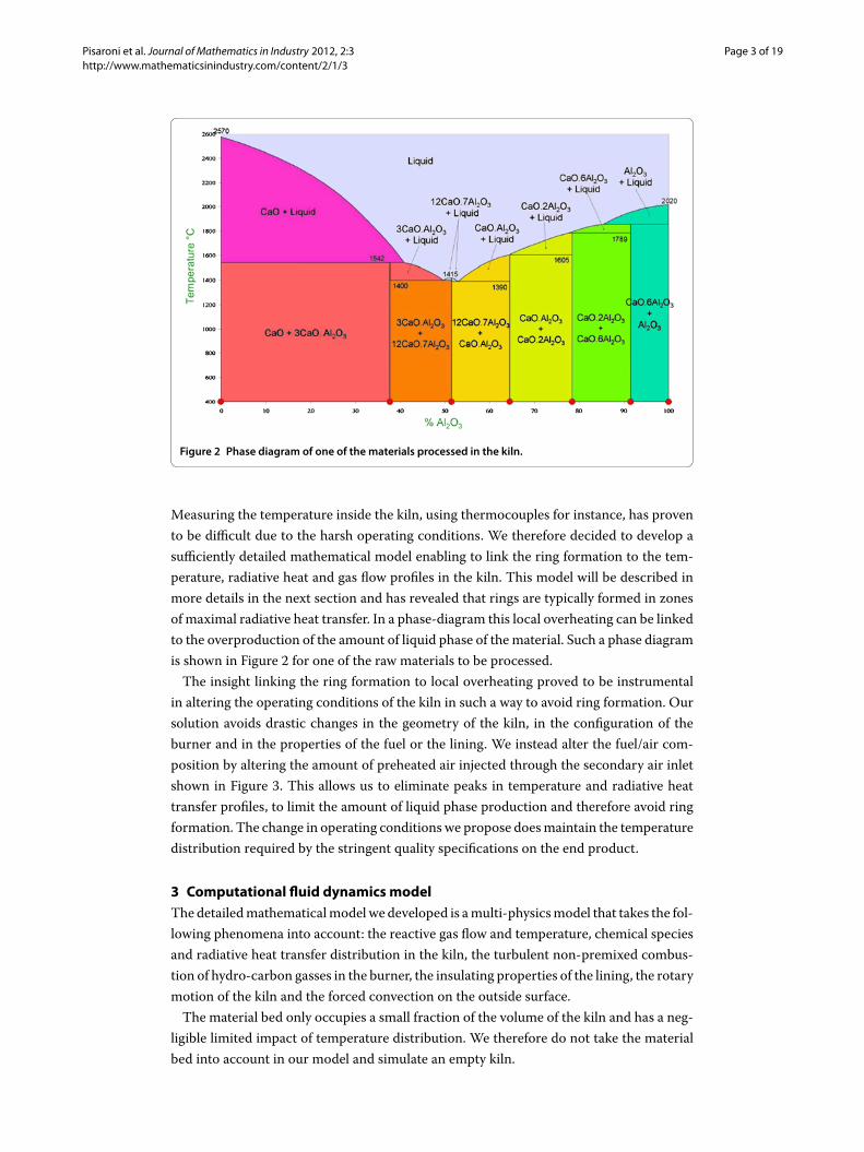
Figure 2 Phase diagram of one of the materials processed in the kiln.
Measuring the temperature inside the kiln, using thermocouples for instance, has provento be difficult due to the harsh operating conditions. We therefore decided to develop asufficiently detailed mathematical model enabling to link the ring formation to the tem-perature, radiative heat and gas flow profiles in the kiln. This model will be described inmore details in the next section and has revealed that rings are typically formed in zonesof maximal radiative heat transfer. In a phase-diagram this local overheating can be linkedto the overproduction of the amount of liquid phase of the material. Such a phase diagramis shown in Figure for one of the raw materials to be processed.The insight linking the ring formation to local overheating proved to be instrumental
in altering the operating conditions of the kiln in such a way to avoid ring formation. Oursolution avoids drastic changes in the geometry of the kiln, in the configuration of theburner and in the properties of the fuel or the lining. We instead alter the fuel/air com-position by altering the amount of preheated air injected through the secondary air inletshown in Figure . This allows us to eliminate peaks in temperature and radiative heattransfer profiles, to limit the amount of liquid phase production and therefore avoid ringformation. The change in operating conditions we propose doesmaintain the temperaturedistribution required by the stringent quality specifications on the end product.
3 Computational fluid dynamics modelThe detailedmathematicalmodel we developed is amulti-physicsmodel that takes the fol-lowing phenomena into account: the reactive gas flow and temperature, chemical speciesand radiative heat transfer distribution in the kiln, the turbulent non-premixed combus-tion of hydro-carbon gasses in the burner, the insulating properties of the lining, the rotarymotion of the kiln and the forced convection on the outside surface.The material bed only occupies a small fraction of the volume of the kiln and has a neg-
ligible limited impact of temperature distribution. We therefore do not take the materialbed into account in our model and simulate an empty kiln.
Pisaroni et al. Journal of Mathematics in Industry 2012, 2:3 Page 4 of 19http://www.mathematicsinindustry.com/content/2/1/3
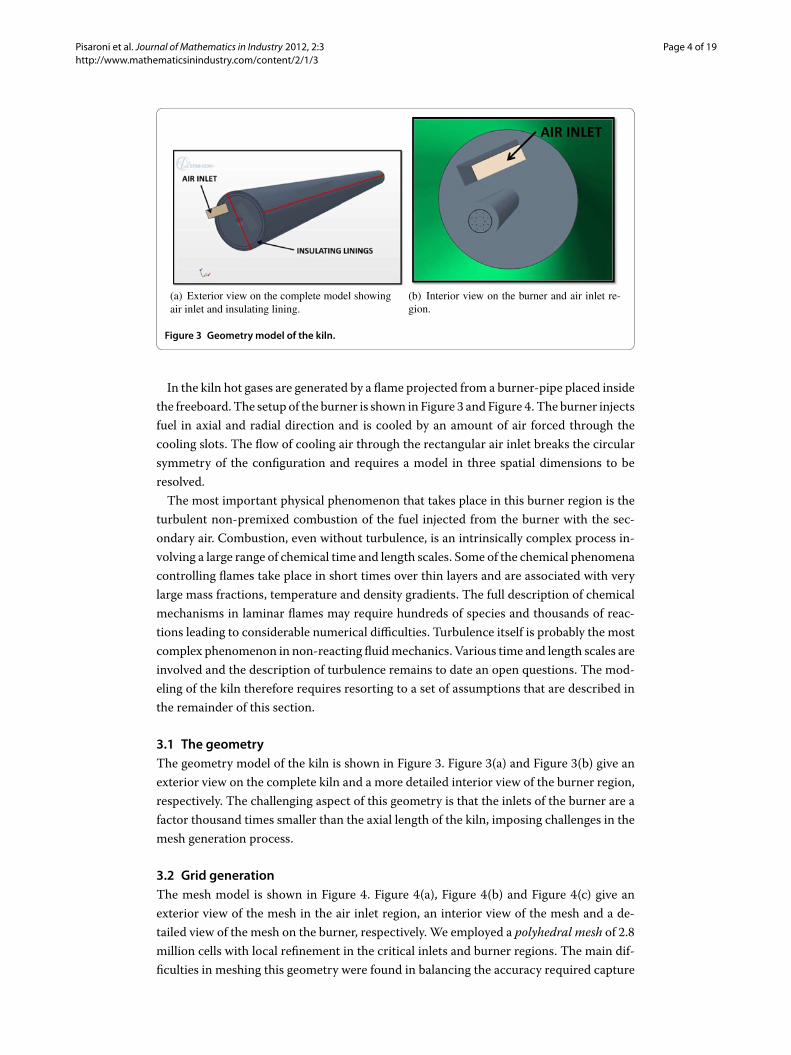
Figure 3 Geometry model of the kiln.
In the kiln hot gases are generated by a flame projected from a burner-pipe placed insidethe freeboard. The setup of the burner is shown in Figure and Figure . The burner injectsfuel in axial and radial direction and is cooled by an amount of air forced through thecooling slots. The flow of cooling air through the rectangular air inlet breaks the circularsymmetry of the configuration and requires a model in three spatial dimensions to beresolved.The most important physical phenomenon that takes place in this burner region is the
turbulent non-premixed combustion of the fuel injected from the burner with the sec-ondary air. Combustion, even without turbulence, is an intrinsically complex process in-volving a large range of chemical time and length scales. Some of the chemical phenomenacontrolling flames take place in short times over thin layers and are associated with verylarge mass fractions, temperature and density gradients. The full description of chemicalmechanisms in laminar flames may require hundreds of species and thousands of reac-tions leading to considerable numerical difficulties. Turbulence itself is probably the mostcomplex phenomenon in non-reacting fluidmechanics. Various time and length scales areinvolved and the description of turbulence remains to date an open questions. The mod-eling of the kiln therefore requires resorting to a set of assumptions that are described inthe remainder of this section.
3.1 The geometryThe geometry model of the kiln is shown in Figure . Figure (a) and Figure (b) give anexterior view on the complete kiln and a more detailed interior view of the burner region,respectively. The challenging aspect of this geometry is that the inlets of the burner are afactor thousand times smaller than the axial length of the kiln, imposing challenges in themesh generation process.
3.2 Grid generationThe mesh model is shown in Figure . Figure (a), Figure (b) and Figure (c) give anexterior view of the mesh in the air inlet region, an interior view of the mesh and a de-tailed view of the mesh on the burner, respectively. We employed a polyhedral mesh of .million cells with local refinement in the critical inlets and burner regions. The main dif-ficulties in meshing this geometry were found in balancing the accuracy required capture

Pisaroni et al. Journal of Mathematics in Industry 2012, 2:3 Page 5 of 19http://www.mathematicsinindustry.com/content/2/1/3
Figure 4 Meshmodel of the kiln.
the flow around small features in the burner with the overall computational cost. Poly-hedral meshes provide a balanced solution in complex mesh generation problems of thiskind.Tetrahedra are the simplest type of volume elements. As their faces are plane segments,
both face and volume centroid locations are well defined. A disadvantage is that tetrahedracannot be stretched too much. To achieve a reasonable accuracy a much larger number ofcontrol volumes is needed than if structuredmeshes are used. Furthermore, as tetrahedralcontrol volumes have only four neighbors, and computing gradients at cell centers usingstandard approximations can be problematic.Polyhedra offer the same automatic meshing benefits as tetrahedra while overcoming
their disadvantages. A major advantage of polyhedral cells is that they have many neigh-bors (typically of order ) allowing gradients to be much better approximated. Obviouslymore neighbors implies more storage and computational operations per cell, but this ismore than compensated by a higher accuracy. Polyhedral cells are also less sensitive tostretching than tetrahedra. A polyhedron with faces for instance has six optimal di-rections which, together with the larger number of neighbors, leads to a more accuratesolution with a lower cell count. Comparisons in many practical tests have verified thatwith polyhedral meshes, one needs about four times fewer cells, half the amount of mem-ory and a tenth to a fifth of computing time compared to tetrahedral meshes to reachsolutions of the same accuracy. In addition, solvers on polyhedral meshes were found to
Pisaroni et al. Journal of Mathematics in Industry 2012, 2:3 Page 6 of 19http://www.mathematicsinindustry.com/content/2/1/3
converge more robustly with respect to change in their parameters. A more detailed anal-ysis of polyhedral meshes can be found in [].
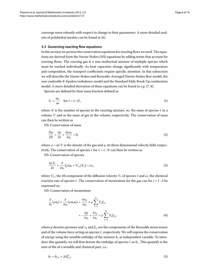
3.3 Governing reacting flow equationsIn this sectionwepresent the conservation equations for reacting flowsweused. The equa-tions are derived from the Navier-Stokes (NS) equations by adding terms that account forreacting flows. The reacting gas is a non-isothermal mixture of multiple species whichmust be tracked individually. As heat capacities change significantly with temperatureand composition, the transport coefficients require specific attention. In this subsectionwe will describe the Navier-Stokes and Reynolds-Averaged Navier-Stokes flowmodel, thenon-realizable K-Epsilon turbulence model and the Standard Eddy Break Up combustionmodel. A more detailed derivation of these equations can be found in e.g. [, ].Species are defined by their mass fraction defined as
Y� =m�
mfor � = :N , ()
where N is the number of species in the reacting mixture, m� the mass of species � in avolume V and m the mass of gas in the volume, respectively. The conservation of masscan then be written asNS: Conservation of mass
Dρ
Dt=
∂ρ
∂t+
∂ρui∂xi
= , ()
where ρ =m/V is the density of the gas and ui its three dimensional velocity field, respec-tively. The conservation of species � for � = :N can then be written asNS: Conservation of species
∂ρY�
∂t+
∂
∂xi(ρ(ui +V�,i)Y�
)= ω�, ()
where V�,i the ith component of the diffusion velocity V� of species � and ω� the chemicalreaction rate of species �. The conservation of momentum for the gas can for j = : beexpressed as:NS: Conservation of momentum
∂
∂t(ρuj) +
∂
∂xi(ρuiuj) =
∂σij
∂xi+ ρ
N∑�=
Y�f�,j
= –∂p∂xj
+∂τij
∂xi+ ρ
N∑�=
Y�f�,j, ()
where p denotes pressure and τij and f�,j are the components of the Reynolds stress tensorand of the volume force acting on species �, respectively. We will express the conservationof energy using the sensible enthalpy of the mixture hs as independent variable. To intro-duce this quantify, we will first denote the enthalpy of species � as h�. This quantify is thesum of the of a sensible and chemical part, i.e.,
h� = h�,s +�hf ,�, ()
Pisaroni et al. Journal of Mathematics in Industry 2012, 2:3 Page 7 of 19http://www.mathematicsinindustry.com/content/2/1/3
where the last term represents the enthalpy of formation of the species at a particular ref-erence temperature T. The enthalpy of the mixture is then defined as a weighted averagethat again can be decomposed into a sensible and chemical part, as follows
h =N∑�=
Y�h� =N∑�=
Y�h�,s +N∑�=
Y��hf ,�
= hs +N∑�=
Y��hf ,�. ()
We will denote the heat diffusion coefficient and the temperature by λ and T , respectively.The energy flux qi is the sum a heat diffusion term derived from Fourier’s Law and a termassociated with the diffusion of species with different enthalpies, i.e.,
qi = –λ∂T∂xi
+ ρ
N∑�=
h�Y�V�,i. ()
In the energy conservation equation the following three source terms will play a role: theheat source due to radiative heat flux denoted as Q, the viscous heating term denoted as, where = τij
∂ui∂xj
and heat release due to combustion denoted as ωT , where
ωT = –N∑�=
�hf ,�ω�. ()
The work done by the gas on the species can be expressed as ρ∑N
�= Y�f�,iV�,i. With allthese quantities introduced, the conservation of energy in terms of hs can be expressed as:NS: Conservation of energy
ρDhsDt
= ωT +DpDt
–∂
∂xi
(λ
∂T∂xi
)+ + Q
–∂
∂xi
(ρ
N∑�=
hs,�Y�V�,i
)+ ρ
N∑�=
Y�f�,iV�,i. ()
Turbulent combustion results from the two-way interaction between chemistry andturbulence. When a flame interacts with a turbulent flow, the combustion modifies theturbulence in two ways. The heat released induces high flow accelerations through theflame front and the temperature changes generate large changes in kinematic viscosity.These phenomena may either generate or damp turbulence and are referred to as flame-generated turbulence and relaminarization due to combustion, respectively. The turbu-lence conversely modifies the flame structure. This may either enhance the chemical reac-tions or completely inhibit it, leading to flame quenching. Compared to premixed flames,turbulent non-premixed flames exhibit some specific features that have to be taken intoaccount. Non-premixed flames do not propagate as they localized on the fuel-oxidizer in-terface. This property is useful for safety purposes but it also has consequences on thechemistry-turbulence interaction. Without propagation speed, a non-premixed flame is
Pisaroni et al. Journal of Mathematics in Industry 2012, 2:3 Page 8 of 19http://www.mathematicsinindustry.com/content/2/1/3
unable to impose its own dynamics on the flow field and is therefore more sensitive toturbulence.The description of the turbulent non-premixed combustion processes in a computa-
tional fluid dynamics model may be achieved using three levels of accuracy in the com-putations. Either a Reynolds Averaged Navier Stokes (RANS), a Large Eddy Simulations(LES) or a Direct Numerical Simulations (DNS) model can be adopted. In current engi-neering practice, the RANSmodel is extensively used because it is less demanding in termsof resources. Its validity however is limited by the closure models describing turbulenceand combustion and the need for some form of callibration. Considering the complexitiesand the dimensions of our kiln, using the RANS model is the only feasible choice.
.. RANS modelIn constant density flows, Reynolds averaging consist in splitting any quantity ξ in meanand fluctuating component (ξ = ξ + ξ ′). In variable density flow Favre [] mass-weightedaverages are usually preferred, i.e., f = ρf
ρ. Any quantity f can therefore be split into:
f = f + f ′′, where f ′′ = .
The RANS equations derived from the reacting Navier-Stokes equation given above arethen given by the equation for conservation of massRANS: Conservation of mass
∂ρ
∂t+
∂ρui∂xi
= , ()
the equation for conservation of species � for � = :NRANS: Conservation of species
∂
∂t(ρY�) +
∂
∂xi(ρuiY�) = ω� –
∂
∂xi(V�,iY� + ρ˜u′′
i Y ′′�
), ()
the equation for conservation of momentum for j = : RANS: Conservation of momentum
∂
∂t(ρuj) +
∂
∂xi(ρuiuj) +
∂p∂xj
=∂
∂xi(τij – ρu′′
i u′′j), ()
and finally the equation for conservation of momentumRANS: Conservation of energy
∂
∂t(ρhs) +
∂
∂xi(ρuihs) = ωT +
DpDt
+∂
∂xi
(λ
∂T∂xi
– ρu′′i h′′
s
)
+ –∂
∂xi
(ρ
N∑k=
hs,�Y�V�,i
). ()
Pisaroni et al. Journal of Mathematics in Industry 2012, 2:3 Page 9 of 19http://www.mathematicsinindustry.com/content/2/1/3
The averaging procedure introduces unclosed quantities that have to bemodeled.Withoutentering in the details we list here the two main unclosed terms that will be described inthe next sections:• Reynolds stresses: ρu′′
i u′′j .
• Species chemical reaction rates: ω�.
.. Turbulence modelUsing the turbulence viscosity assumption by Boussinesq [], the Reynolds stresses canbe represented as
ρu′′i u′′
j = ρu′′i u′′
j
= –μt
(∂ui∂xj
+∂uj∂xi
–δij
∂uK∂xK
)+ρk, ()
where μt = ρνt is the turbulent dynamic viscosity and δij the Kronecker delta. The turbu-lent kinetic energy k in turn can be expressed as
k =
∑j=
u′′j u′′
j . ()
Modeling the turbulent viscosity μt is the central problem in turbulence computations.Many approaches exist. In this work we use a classical turbulence model developed fornon-reacting flows, namely theRealizable K-Epsilonmodel []. Heat release effects on theReynolds stresses are not explicitly taken into account in this approach and the turbulentviscosity is modeled as
μt = ρCμ
k
ε, ()
where ε is the rate of energy dissipation. In this model the critical coefficient Cμ is a func-tion of mean flow and turbulence properties, rather than assumed to be constant as inthe standardmodel. This allows to satisfy certain mathematical constraints on the normalstresses consistent with the physics of turbulence and is referred to as realizability.From the Boussinesq relationship in Equation () and the eddy viscosity definition in
Equation () it is possible to obtain the following expression for the normal Reynoldsstress u in an incompressible strained mean flow U
u =k – νt
∂U∂x
, ()
where νt = μtρ. It can be shown that u, which by definition is a positive quantity, become
negative (non-realizable), when the strain is large enough to satisfy
kε
∂U∂x
>
Cμ
≈ .. ()
The easiest way to ensure the realizability is to make Cμ in () variable [].

Pisaroni et al. Journal of Mathematics in Industry 2012, 2:3 Page 10 of 19http://www.mathematicsinindustry.com/content/2/1/3
The critical coefficientCμ can be expressed as a function of themean strain and rotationrates, the angular velocity of the system rotation and the turbulence fields as follows
Cμ =
A +AskU*ε
, ()
where
U* =√SijSij + �ij�ij, ()
�ij = �ij – εijkωk and �ij = �ij – εijkωk , ()
where �ij is the mean rate of rotation tensor viewed in a rotating reference frame with theangular velocity ωk . The parameters A and As in () can be computed as
A = ., As =√ cosφ, ()
φ =
cos–(√W ), ()
W =SijSjkSki
S, S =
√SijSij, ()
Sij =
(∂uj∂xi
+∂ui∂xj
). ()
The turbulent kinetic energy k and its dissipation rate ε in Equation () are describedby the following two balance equations
∂
∂t(ρk) + ∂
∂xi(ρkui) =
∂
∂xj
[(μ +
μt
σk
)∂k∂xj
]+ Pk + Pb – ρε – YM + Sk , ()
∂
∂t(ρε) +
∂
∂xi(ρεui) =
∂
∂xj
[(μ +
μt
σε
)∂ε
∂xj
]
+Cεε
k(Pk +CεPb) –Cερ
ε
k+ Sε , ()
where Pk is the production term of turbulent kinetic energy due to the mean velocity gra-dients, Pb the production of turbulent kinetic energy due to buoyancy, YM the dilatationdissipation term that accounts for the contribution of the fluctuating dilatation in com-pressible turbulence to the overall dissipation rate, Sk and Sε user defined source terms forturbulent kinetic energy and dissipation, and σk and σε the turbulent Prandtl numbers fork and ε, respectively. Cε , Cε and Cε are model constants.Another weakness of traditional K-Epsilon turbulence models is their modeling of the
dissipation rate ε. Indeed, the well-known spreading (or dispersion) rate anomaly refersto the fact that traditional models do reasonably well in predicting the spreading rate ofa planar jet but perform unexpectedly poor for rounds jets. This weakness can be tracedback to a deficiency in traditional ε-equations. The realizable model proposed by Shih []was developed to repair this deficiency and addresses as such an issue that is of primaryimportance in our study.
Pisaroni et al. Journal of Mathematics in Industry 2012, 2:3 Page 11 of 19http://www.mathematicsinindustry.com/content/2/1/3
.. Combustion modelThe averaged equation for conservation of species () can be rewritten in compact formfor � = :N as
∂
∂t(ρY�) +
∂
∂xi(ρuiY�) = –∇ · J� + ω�, ()
where J� is the mass diffusion flux of species �. The previous equation is solved in a CFDcode forN – species whereN is the total number of fluid phase chemical species presentin the system. Since the mass fraction of the species must sum to unity, theN th mass frac-tion is determined as one minus the sum of the N – solved mass fractions. To minimizenumerical error, theN th species should be selected as that species with the overall largestmass fraction.In turbulent flows the mass diffusion flux is computed as
J� = –(
ρD� +μt
Sct
), ()
where Sct is the turbulent Schmidt number andD� is themolecular diffusivity of species �.The species chemical reaction rate unclosed term ω� must be modeled with a combus-
tionmodel. A combustionmodel describes the two-way interaction between properties ofthe turbulent flow produced by the flame and the chemical reactions. It serves to computethe reaction state space and the quantities it influences, namely the fluid density, viscosity,and temperature. It accounts for the processes that occur at length and time scales thatwe cannot resolve on a grid either in space or time due to limitations in computational re-sources. The choice of combustion model is decided by knowing the Damkohler number,defined as Da = tmix
trxn , where tmix is the mixing time scale and trxn is the reaction time scale.When the Damkohler number is very large, as in the case of the kiln, the reaction rate iscontrolled by the turbulent mixing that brings reactants together at the molecular scale.In this limit, the Standard Eddy Break Up (EBU) [] model is fairly accurate because itassumes that the reaction occurs instantaneously upon micromixing.The EBU combustion model tracks individual mean species concentrations on the grid
through transport equations. The reaction rates used in these equations are calculated asfunctions of the mean species concentrations, turbulence characteristics and, dependingon the specific model used, temperature. A mean enthalpy equation is solved in additionto the species transport equations. The mean temperature, density and viscosity are thencalculated knowing the mean enthalpy and species concentrations. In the EBU used, theindividual species in the global reaction are assumed to be transported at different ratesaccording to their own governing equations.The reaction rate is modeled through an expression that takes the turbulent micromix-
ing process into account. This is done through dimensional arguments. Thus, for a reac-tion of the form
vFF + vOO –→ vPP + vPP + · · · + vPjPj, ()
Pisaroni et al. Journal of Mathematics in Industry 2012, 2:3 Page 12 of 19http://www.mathematicsinindustry.com/content/2/1/3
where F stands for fuel, O oxidiser and P products of the reaction, the reaction rate forreaction � is assumed to be
ω� =ρ
M
(
τmix
)Aebu min
{YF ,
YO
sO,Bebu
(YP
sP+ · · · + YPj
sPj
)}, ()
where sO = vOMOvFMF
, sPj =|vPj|MPjvFMF
, v is the molar stoichiometric coefficient for species j inreaction �,M is molecular weight of species. Equation () essentially states that the inte-grated micromixing rate is proportional to the mean (macroscopic) concentration of thelimiting reactant divided by the time scale of the large eddies ( k
ε= τmix). YF , YO, YP are
respectively the mean concentrations of fuel, oxidizer, and products. Aebu and Bebu aremodel constants with typical values of . and . respectively. The values of these con-stants are fitted according to experimental results and they are suitable for most cases ofgeneral interest.In our simulations we used a reduced combustion mechanism with species and re-
actions to account for a fuel that is a mixture of different alkanes. This mixture consistsfor % of CH and for % of CH, CH and CH.The above models are discretized by a finite volume technique using second order up-
winding for the convective terms [–]. The flowequations are solved in a segregated ap-proach inwhich the SIMPLE algorithm realizes the velocity-pressure coupling. The energyequation is solved for the chemical thermal enthalpy using again a segregated approach.The temperature is computed from the enthalpy according to the equation of state. Ateach outer non-linear iteration the resulting linear systems are solved using an algebraicmultigrid preconditioner for a suitable Krylov subspace acceleration [].
3.4 Additional informationIn situations in which the media separating hot walls is transparent for thermal radiationas in the case of dry air, radiation can only occur as a surface phenomenon. In the ourcase however, the gas in the freeboard of the kiln will absorb, emit and scatter the thermalradiation intensity emitted from the hot walls of the kiln. This process is governed by theradiative transfer equation (RTE) that is implemented in a Participating Media RadiationModel. The model is discretized in solid angle by the discrete ordinate method describedin detail in [, ].
3.5 Software implementationSimulations were performed using the STAR-CCM+ software suite [] on a ten-nodesLinux cluster having Intel Duo and Quad Core processors at a clock speed between. GHz and . GHz running a Slackware -bit distribution. Iterating the three-dimensional combustion model to equilibrium state required between , and ,non-linear iterations and between three and three and a half days of computation time.
4 Computational resultsIn this section we discuss how our combustion model validates the difference betweentwo operating conditions of the oven. These operating conditions are listed in Table anddiffer in the amount of preheated air that flows through the secondary air inlet shown inFigure . In the first and second line in Table the ratio of volume air to volume of fuel
Pisaroni et al. Journal of Mathematics in Industry 2012, 2:3 Page 13 of 19http://www.mathematicsinindustry.com/content/2/1/3
Table 1 Standard and new configuration of operating conditions of the kiln
Operating conditions Air to fuel ratio
Standard 9New 12
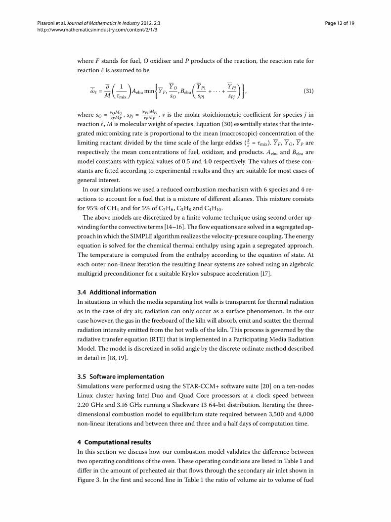
Figure 5 Effect of change in operating conditions on the streamlines of methane and oxigen in thekiln.
equals nine and twelve, respectively. The ratio of nine corresponds to the kiln’s operationconditions that were commonly used before the start of this work and will be referred toas the standard operating conditions. The ratio of twelve correspond to the new operationconditions that we propose. In switching from the standard to the new configuration, theflux of fuel injected in axial and radial direction and the flux of air through the coolingslot is kept the same. The effect of this switch in operation conditions on the mass ofoxygen andmethane is shown in Figure . This figure shows that with in the new operatingconditions the oxigen is transported further down in the kiln.The objective of this section is to show how according to the combustion model de-
scribed in the previous section the new configuration is less prone to the development ofrings than the standard configuration. The two key arguments in this demonstration are
Pisaroni et al. Journal of Mathematics in Industry 2012, 2:3 Page 14 of 19http://www.mathematicsinindustry.com/content/2/1/3
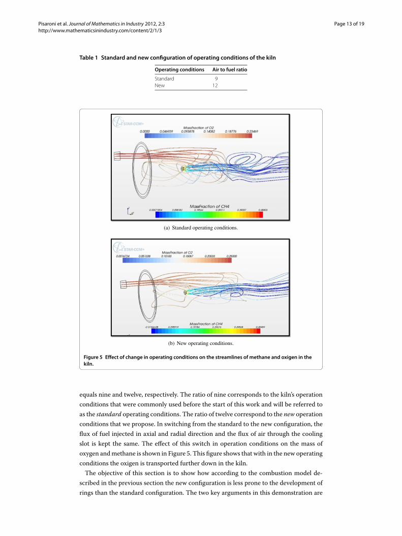
Figure 6 Effect of change in operating conditions on the temperature on an axial section of the kilnthrough the air inlet.
Figure 7 Temperature vs. position (blue standard operating conditions, red new operatingconditions).
the temperature and radiative heat distribution on the inside wall of the kiln. These willbe elaborated separately in the two subsections.
4.1 Effect on temperatureIn Figure , Figure and Figure we show how the change in operating conditions af-fects the computed temperature profile. Figure shows the temperature distribution onan axial section through the air inlet. Figure shows the temperature evaluated at the cen-troid of each cell of the surfacemesh on the inside wall versus the centroid’s axial distance.

Pisaroni et al. Journal of Mathematics in Industry 2012, 2:3 Page 15 of 19http://www.mathematicsinindustry.com/content/2/1/3
Figure 8 Effect of change in operating conditions on the temperature on the inside wall of the kiln.
This wall forms the interface between the hot gas and the innermost part of the insulat-ing lining. For positions closer to low end of the kiln the temperature values shown varymore with the circumferential angle due to the higher temperature gradients caused bythe injected air. The lines in Figure are therefore thicker for small values of the abscis.Figure finally shows the temperature distribution on the inside wall of the kiln. In thisfigure the flame propagating from the burner is represented by an iso-surface that enclosesa region in which the methane concentration is larger than or equal to .. The verticaland horizontal color bars indicate the temperature of the flame and the wall, respectively.Figure clearly illustrates the effect of switching to the new operating conditions as it
shows in the new conditions, the relatively cold preheated air is transported further intothe kiln acting as a coolant on the wall. Figure shows that this coolant reduces the wallpeak temperature drops by .% from , degrees Celcius to , degrees Celcius. Italso shows that switching to the new operating conditions does not significantly alter theglobal distribution characteristics of the temperature which is of paramount importancein the material production process. Figure is particularly interesting as it shows that inboth configurations the peak in temperature is situated in a zone at four and halve to sevenmeters from the burner. This zone coincides with the zone in which rings are typicallyformed. It is therefore plausible that a reduction in peak temperature by switching to thenew operating conditions will result in a reduction of the amount of liquid phase of thematerial being formed, and therefore impede the formation of rings. This hypothesis willbe confirmed by looking into the computed radiative heat transfer distribution as we willdo in the next subsection.
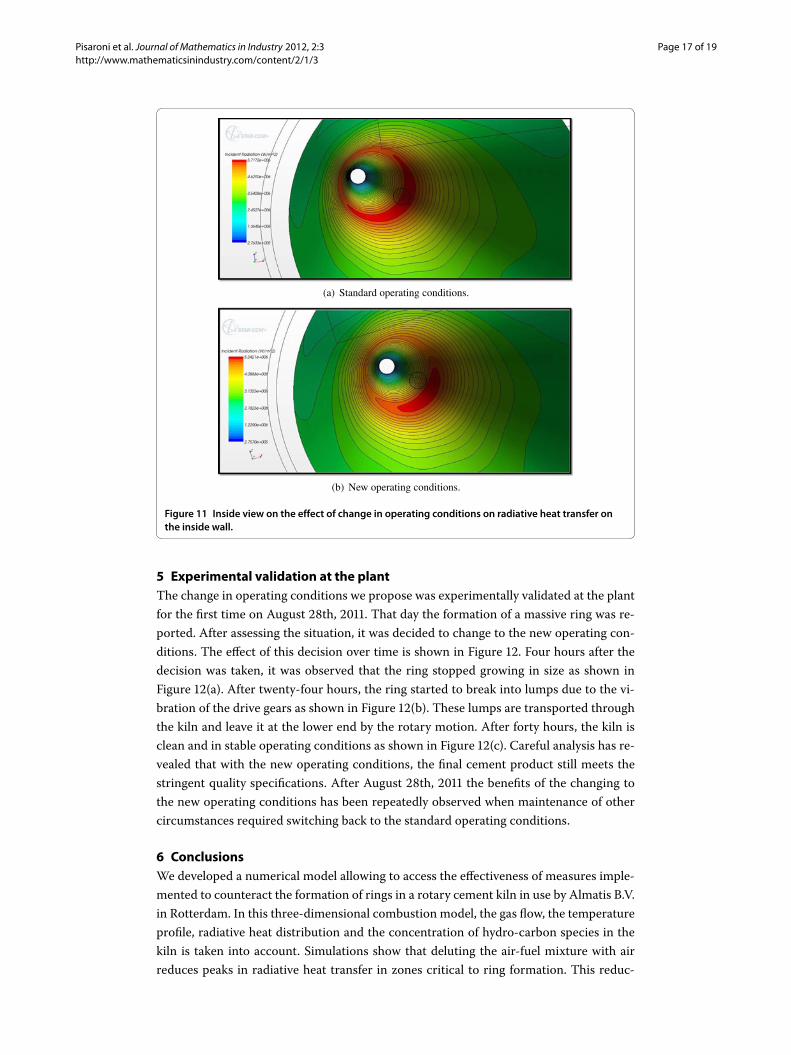
4.2 Effect on radiative heat transferIn Figure , Figure and Figure and we show how the change in operating condi-tions affects the computed radiative heat transfer on the inside wall of the kiln. Figure
Pisaroni et al. Journal of Mathematics in Industry 2012, 2:3 Page 16 of 19http://www.mathematicsinindustry.com/content/2/1/3
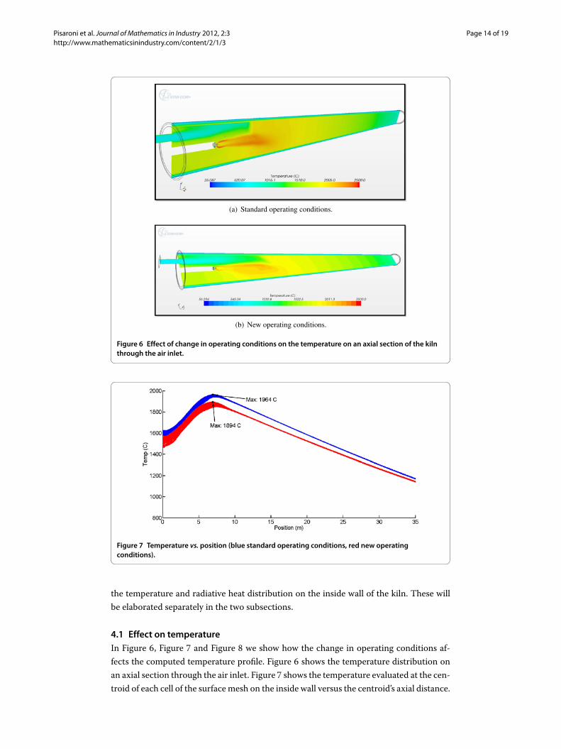
Figure 9 Outside view on the effect of change in operating conditions on radiative heat transfer onthe inside wall.
Figure 10 Incident radiation vs. position (blue standard operating conditions, red new conditions).
and Figure are the equivalent for radiative heat transfer of Figure and Figure forthe temperature, respectively. Figure finally gives an view on the radiative heat transferdistribution from the inside of the kiln.Figure confirms that as expected changing to the new operating conditions results in
a lowering of the peak in radiative heat transfer. Figure shows that peak in the radiativeheat transfer drops by .% from ,,W/m to ,,W/m and that the regionof high values is reduced in size. Figure gives another representation of this fact. Byswitching to the new operating conditions, the material in the kiln is less likely to absorban excessive amount of heat, effectively limiting the amount of liquid phase of thematerialand therefore the formation of rings.
Pisaroni et al. Journal of Mathematics in Industry 2012, 2:3 Page 17 of 19http://www.mathematicsinindustry.com/content/2/1/3
Figure 11 Inside view on the effect of change in operating conditions on radiative heat transfer onthe inside wall.
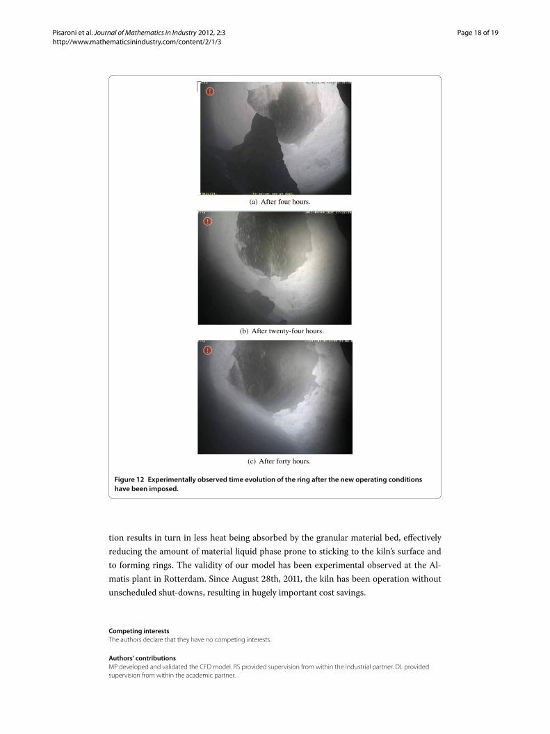
5 Experimental validation at the plantThe change in operating conditions we propose was experimentally validated at the plantfor the first time on August th, . That day the formation of a massive ring was re-ported. After assessing the situation, it was decided to change to the new operating con-ditions. The effect of this decision over time is shown in Figure . Four hours after thedecision was taken, it was observed that the ring stopped growing in size as shown inFigure (a). After twenty-four hours, the ring started to break into lumps due to the vi-bration of the drive gears as shown in Figure (b). These lumps are transported throughthe kiln and leave it at the lower end by the rotary motion. After forty hours, the kiln isclean and in stable operating conditions as shown in Figure (c). Careful analysis has re-vealed that with the new operating conditions, the final cement product still meets thestringent quality specifications. After August th, the benefits of the changing tothe new operating conditions has been repeatedly observed when maintenance of othercircumstances required switching back to the standard operating conditions.
6 ConclusionsWe developed a numerical model allowing to access the effectiveness of measures imple-mented to counteract the formation of rings in a rotary cement kiln in use by Almatis B.V.in Rotterdam. In this three-dimensional combustion model, the gas flow, the temperatureprofile, radiative heat distribution and the concentration of hydro-carbon species in thekiln is taken into account. Simulations show that deluting the air-fuel mixture with airreduces peaks in radiative heat transfer in zones critical to ring formation. This reduc-
Pisaroni et al. Journal of Mathematics in Industry 2012, 2:3 Page 18 of 19http://www.mathematicsinindustry.com/content/2/1/3
Figure 12 Experimentally observed time evolution of the ring after the new operating conditionshave been imposed.
tion results in turn in less heat being absorbed by the granular material bed, effectivelyreducing the amount of material liquid phase prone to sticking to the kiln’s surface andto forming rings. The validity of our model has been experimental observed at the Al-matis plant in Rotterdam. Since August th, , the kiln has been operation withoutunscheduled shut-downs, resulting in hugely important cost savings.
Competing interestsThe authors declare that they have no competing interests.
Authors’ contributionsMP developed and validated the CFD model. RS provided supervision from within the industrial partner. DL providedsupervision from within the academic partner.
Pisaroni et al. Journal of Mathematics in Industry 2012, 2:3 Page 19 of 19http://www.mathematicsinindustry.com/content/2/1/3
Author details1Scientific Computing Group, Delft Institute of Applied Mathematics, Faculty of Electrical Engineering, Mathematics andComputer Science, Delft University of Technology, Delft, The Netherlands. 2Almatis B.V., Theemsweg 30, Botlek,Rotterdam, 3197 KM, The Netherlands.
AcknowledgementsWe thank Marco Talice for his advice worth more than platina and the CD-ADAPCO London office for the support in usingtheir software.
Received: 27 April 2012 Accepted: 9 October 2012 Published: 24 October 2012
References1. Boateng AA: Rotary Kilns: Transport Phenomena and Transport Processes. Stoneham: Butterworth-Heinemann; 2006.2. Mastorakos E, Massias A, Tsakiroglou CD, Goussis DA, Burganos VN, Payatakes AC: CFD predictions for cement kilns
including flamemodelling, heat transfer and clinker chemistry. Appl MathModel 1999, 23(1):55-76.3. Marias F, Roustan H, Pichat A:Modelling of a rotary kiln for the pyrolysis of aluminium waste. Chem Eng Sci 2005,
60(16):4609-4622.4. Giannopoulos D, Kolaitis DI, Togkalidou A, Skevis G, Founti MA: Quantification of emissions from the
co-incineration of cutting oil emulsions in cement plants: part i: NOx , CO and VOC. Fuel 2007, 86(7-8):1144-1152.5. Tran HN, Barham D: An overview of ring formation in lime kilns. Tappi J 1991, 74(1):131-136.6. Peric M: Flow simulation using control volumes of arbitrary polyhedral shape. ERCOFTAC Bulletin September 2004, 62.7. Williams FA: Combustion Theory. 2nd edition. New York: Westview Press; 1994.8. Kuo KK: Principles of Combustion. 2nd edition. New York: Wiley-Interscience; 2005.9. Poinsot T, Veynante D: Theoretical and Numerical Combustion. 2nd edition. Ann Arbor: Edwards; 2005.10. Hinze JO: Turbulence. New York: McGraw-Hill; 1975.11. Shih TH, Liou WW, Shabbir A, Zhu J: A new k-ε Eddy-viscosity model for high Reynolds number turbulent flows -
model development and validation. Comput Fluids 1995, 24(3):227-238.12. Reynolds WC: Fundamentals of Turbulence for TurbulenceModeling and Simulation; 1987. [Lecture Notes for Von Karman
Institute.] (Agard Report No. 755.)13. Magnussen BF, Mjertager BH: Onmathematical modeling of turbulent combustion. In 16th Symp. (Int.) on
Combustion. Pittsburgh: The Combustion Institute; 1976: 719-727.14. Demirdzic I, Peric M: Finite volumemethod for prediction of fluid flow in arbitrarily shaped domains with moving
boundaries. Int J Numer Methods Fluids 1990, 10(7):771-790.15. Mathur SR, Murthy JY: A pressure-based method for ustructured meshes. Numer Heat Transf, Part B, Fundam 1997,
31(2):195-215.16. Murthy JY, Mathur SR: Radiative heat transfer in axisymmetric geometries using an unstructured finite-volume
method. Numer Heat Transf, Part B, Fundam 1998, 33(4):397-416.17. Trottenberg U, Oosterlee C, Schüller A:Multigrid. San Diego: Academic Press; 2001.18. Modest MF: Radiative Heat Transfer. New York: McGraw-Hill; 1993.19. Siegel R, Howell JR: Thermal Radiation Heat Transfer. 3rd edition. Washington: Hemisphere; 1992.20. Star-CCM+ Version 6.06.011 user guide; 2011.
doi:10.1186/2190-5983-2-3Cite this article as: Pisaroni et al.: Counteracting ring formation in rotary kilns. Journal of Mathematics in Industry 20122:3.