Corrigendum-III, Part-A (Reply to Bidder's queries) Tender ... · PDF fileCorrigendum-III,...
32
Transcript of Corrigendum-III, Part-A (Reply to Bidder's queries) Tender ... · PDF fileCorrigendum-III,...

Corrigendum-III, Part-A (Reply to Bidder's queries) Tender No. N1Tr-03/2016
Overall SN
Vol No. Clause no. Bid Condition Bidder's Queries NMRCL's Response
1 Part 2 – Section VII-BParticular Specifications
Clause 3.2.5 (f)
Clause 3.2.8.3 (C) (P 26/167)
Clause 7.4(P 86/167)
Retractable catenary system at inspection lines of both the depots
Retractable catenary system in Inspection Bay (including that for Mihan depot).
Retractable catenary system to be installed in inspection and heavy repair lines of depots
It is difficult to estimate the length of Retractable catenary system to be installed in inspection and heavy repair lines of both the depots with drawings provided along with Tender. Therefore it is requested to share the Auto Cad drawings / alternate drawings along with length of tracks wherein Retractable Catenary is to be provided.
Auto CAD drawings are attached along with Addendum
2 Part 2 – Section VII-BParticular Specifications
Clause 2.3.2 (P 22/167)
Tubular portal structures for OCS
NMRCL has planned to use tubular portal structures for supporting OCS throughout the ………………mainlines. ……………………….. from RDSO and other relevant statutory authorities.
As we are aware there are no / limited approved vendor from RDSO / CORE available for these type of poles. We are also aware that obtaining approval from the above institutions is an arduous process which can hugely affect the timelines of this project.
In view of above we suggest employer’s approval for this product instead of approval from RDSO / CORE.
Clause 2.3.2 of PS amended
Refer to Addendum
3 Part 2 – Section VII-BParticular Specifications
Clause 3.1.7 (P 23/167)
Electrical Work Permits plan
The scope of work includes the design of an Electrical Work Permits plan …………(a) organizing meeting on a weekly basis with other contractors to list the needs of electrical work permits issuance(b) issuing and collecting back electrical works permits from contractors
For finalizing the Electrical Work Permit Plan , it would be difficult for OCS contractor to hold the meeting with other contractors as other Contractors are not in the control of OCS contractor. Further issuing and collecting back electrical works permit from contractors also come in the prerogative of Employer or Employer’s nominated Engineer.
It is therefore requested to suitably modify the clause 3.1.7 a and b to include it in the scope of Employer
The scope under clause 3.1.7 pertains to OHE Contractor to extent of his scope of work. The clause 3.1.7 has been suitably modified to make it more explicit.
Refer to Addendum
4 Part 2 – Section VII-BParticular Specifications
Clause 3.2.5 (P 24/167)
Scope of Work Clause explain the scope of work as design, supply, installation, inspection, testing and commissioning of: feeding arrangement at FP, SSP, sub sectioning etc with Suitable Protection arrangement
We understand that all protection devices: for feeding arrangement at FP, SSP, sub sectioning etc are installed at Traction Substation 25 kV Circuit breaker to executed by PST contractor.
Kindly confirm our understanding
Your understanding is generally correct. However, protections may be required at some sectioning posts (e.g. depot SSP - incoming feeder from mainline), which shall be in the scope of OHE Contractor. The clause 3.2.5 (a) is modified to make the matter more explicit.
Refer to Addendum5 Part 2 – Section
VII-BParticular Specifications
Clause 3.29 (P 26/167)
Civil Works and Ancillary InstallationsThe Contractor will be required to execute civil, finish & utility works at the Higna depot SSP location. The earthing work (earthmat, maintenance free earthing etc.) shall also be in the scope of Contractor for Higna Depot SSP.
It is understood that relevant Civil work are to be executed at the Higna Depot SSP. However as per clause 1.3 ITB the scope of work at Mihan depot in this contract is limited to Retractable OCS only.
In view of the above, please confirm that No civil works comes under the scope of work of OCS contractor for Mihan Depot
Confirmed
6 Part 2 – Section VII-BParticular Specifications
Clause 3.6.11 (P 28/167)
It is motioned that The Contractor shall install mock-up equipment for system ----------------for the training of Employer’s staff in the Mihan / Higna Depot training centre.
However as per clause 1.3 ITB the scope of work at Mihan depot in this contract is limited to Retractable OCS only.
In view of the above our understanding towards mock up for training is required under the scope of this contract at Higna Depot only.
Kindly confirm our understanding.
NMRCL will decide the location of training center and thus location of mockup. However, it is confirmed that mockups will not be repeated at other places.
No changes foreseen.7 Part 2 – Section
VII-BParticular Specifications
Clause 4.2.7.3 (P 32/167)
The availability of the Overhead Collection System shall be greater than 99.99%..
It is requested to amend the clause as “The availability of the Overhead Collection System shall not be less than 99.99%..
Clause 4.2.7.3 amended
Refer to Addendum

Overall SN
Vol No. Clause no. Bid Condition Bidder's Queries NMRCL's Response
8 Part 2 – Section VII-BParticular Specifications
Clause 5.3.1.4 (P 38/167)
TRACTION NETWORKClause specifies that “The protection relays required for protection of Traction Feeders (Over current, Distance) and for protection against ‘Panto flash over’ and ‘Wrong phase coupling’ at Neutral Sections, shall be provided by the Contractor.”
It is understood that Protection Relays will be provided in the Traction Substation (i.e. 25kV CBs with all required protective features ), and are a part of PST contract , which is not in the scope of this Tender.
As all SSP, Sub Sectioning, etc are having the Interrupters (BM) only therefore, Protection Relays will not fall in the ambit of this tender for Main Line.
Please confirm.
Please refer Note under Clause 5.3, which is self-explanatory
No changes foreseen
9 Part 2 – Section VII-BParticular Specifications
Clause 5.4.10 (P 54/167)
The Emergency Trip Switches will be used for switching off the Traction Power Supply of corridor 1 and 2 or depot in case of emergency. The ETS switches are installed in OCC/BCC and at each RSS.
Please confirm whether ETS system at Stations, OCC/BCC and RSS will be provided by other contractors.
Please refer Note under Clause 5.4 together with clause 5.4.10, which are self-explanatory
No changes foreseen10 Part 2 – Section
VII-BParticular Specifications
Clause 6.3.1.g, h , I (P 57/167)
Traction Substation
The Traction Substation mainly comprises of:--------------
(g) All interconnecting power cables, including 25kV cables from TSS exit point upto the Interrupter/isolator located on the viaduct, for feeding the OHE
(h) All return cables from the track-side Impedance bonds to the buried rail at TSS and onwards to the traction transformer
(i) All control and monitoring cables for necessary connection of equipments ……”
Our understanding is that the scope cover under these clause will be facilitated by PST contractor and will not be a part of scope of work of OHE / OCS contractor
Refer to Note under Clause 6.3.1, which is self explanatory. For scope demarcation regarding TSS to FP cables and other relevant cables, please refer to Appendix A.
No changes foreseen
11 Part 2 – Section VII-BParticular Specifications
Clause 6.3.2.2 (P 58/167)
27.5 kV Switchgear
This switchgear shall comprise:
(a) Incoming circuit breakers and interrupter with associated Isolators(b) Bridging and paralleling interrupter(c) motorized isolators(d) associated measuring, controlling, monitoring, and protecting devices(e) These apparatuses shall be structure mounted with the switching apparatus at pole top level and control equipment at hand level along with transmitting mechanism.
Please confirm that for structure mounted 25 kV Bridging and paralleling interrupter, Motorized Isolators, etc on the main line viaduct, 110 V DC control supply for control and monitoring will be provided (up to the viaduct) by other contractors by extending the feed from battery / battery charger located at ASS /TSS
Please refer to Appendix A for scope demarcation of control & power cables. It is clarified that power & control cables from SSP/SS/FP to station room (ASS, RTU) are under the scope of OHE Contractor.
No changes foreseen
12 Part 2 – Section VII-BParticular Specifications
Clause 6.4.2.19 (P 64/167)
Depot design requirement: Please provide the length of Test Track, stabling lines and their number, etc for provision of OHE.
Refer to tender drawings
13 Part 2 – Section VII-BParticular Specifications
Clause 6.4.5.1.4 (P 66/167)
Installation of Feeding SystemThe interrupters and isolators meant for sectioning shall be located in the station area in a room close to the sections required to reduce length of cables.
Please confirm whether Interrupters am Isolators meant for sectioning shall be located in the station area in a room or these will be structure mounted. In either case these equipments will be of Outdoor AIS.
These shall be structure mounted near the stations on viaduct. The clause 6.4.5.1.4 is modified.
Refer to Addendum14 Part 2 – Section
VII-BParticular Specifications
Clause 7.1.3.2 (P 75/167)
SSP RoomAs part of the Depot SSP Building, the Contractor is required to build the Higna Depot SSP Room complete with cable gallery, cable paths, covers and other general electrical facilities such as lighting, ventilation, fire detection & alarm, earthing system etc.
It is comprehended that LV supply ACDB, DC DB, 110 V DC supply for control and monitoring will be tapped from the Depot ASS and same will be available in the SSP.
Please confirm the above.
Please referAppendix A for demarcation / interface responsbility among contractors.

Overall SN
Vol No. Clause no. Bid Condition Bidder's Queries NMRCL's Response
15 Part 2 – Section VII-BParticular Specifications
Clause 7.2.14.1& 2(P 82/167)
Automatic Tensioning Device
5-pulley type automatic tensioning devices along with protective cage (for weights) shall be provided for about 80% of the requirements.
For remaining 20% of the requirements, Spring Auto Tensioning Device shall be provided
Our understanding is that these quantities will be measured on the total volume including the complete section and not individual section.
Kindly confirm our understanding.
NMRCL has decided to go for 100% spring type ATDs including in depots. The clause 7.2.14.1 & 2 and 3.2.8.4 (n) amended.
Refer to Addendum
16 Part 2 – Section VII-BParticular Specifications
Clause 7.4.3.2.(P 87/167)
Minimum Electrical and Mechanical Clearance- 25kV Live metal to earth
As per table 7.1 in tender Static 270mm Dynamic (passing) 170 mm
As per IEC 60913 , 2013 Static 270mm Dynamic (passing) 150 mm
Please confirm Minimum Electrical and Mechanical Clearance- 25kV Live metal to earth as depicted in Table 7.1 (i.e. 170 mm ) shall have to be considered
or
wherever due to non availability of space, clearance as stipulated in IEC 60913, 2013 ( i.e. 150 mm ) can be considered in the design
These are detailed design stage matters and to be dealt with appropriately at that time. IEC 60913 (or other relevant standards) to be followed and in case latest version of standards has amended the requirements, the same can be accepted after appropriate deliberation / diligence.
No changes foreseen17 Part 2 – Section
VII-BParticular Specifications
Clause 7.4.3.9 (P 89/167)
Clause 7.2.3.1(P 89/167)
Rigid conductor rail and contact wireContact Wire shall be Round Bottom, 150 sq mm area and shall comply with EN 50149.
For main line , The contact wire shall be of 150 sq mm hard drawn grooved, flattened copper conductor, as per EN 50149 configurations similar to BF-150.
For Main Line, Contact wire to be provided is 150 sq mm hard drawn grooved, flattened copper as per EN 50149 , whereas for Rigid OCS, it is Round Bottom, 150 sq mm as per EN 50149.
Since the quantity of Rigid OCS to be provided will be substantially small as per scope of work, therefore it would be extremely difficult to get such small length of Round Bottom, 150 sq mm Contact wire.
In view of above, it is requested to permit the use of contact wire of 150 sq mm hard drawn grooved, flattened copper for Rigid OCS also similar to the mainline which will reduce the maintenance inventory in future.
Clause 7.4.3.9 amended
Refer to Addendum
18 Part 2 – Section VII-BParticular Specifications
Clause 7.5.1.2(P 91/167)a few
Contractor’s Agreement with Structure Manufacturers (TUBULAR STEEL STRUCTURES FOR SUPPORTING OCS)
……..The manufacturer shall make a written agreement with the Contractor for providing design and manufacturing support for the project. ……………………………., Copy of the agreement shall be submitted.
In case the structure manufacturer ………is a multinational company, they should have a registered subsidiary company in India for their Indian operations.
The following requirements will be instrumental in restricting the competitiveness and influence the Bid Cost in a huge way.
1.0 Requirement of multinational company (responsible for design and supply), they should have a registered subsidiary company in India for their Indian operations
They should also have production facilities in India for manufacturing for this requirement. Proof of this shall be submitted.
The Indian subsidiary should also have facility for providing after sale supports to the contractor / Employer in India.
In view of the above it is requested to remove these conditions and open the specification for standard Steel Poles / Masts / Portals as well to improve price competitiveness.
Further following stringent conditions need to relaxed a) Minimum international experience of 10 years (Relax to 2 years ) in design, manufacturing and supply of utility structures.
b) The manufacturer should also have conducted 4 (relax to 1 ) full-scale testing of poles in NABL accredited independent lab in past 4 years ( Relax to 10 years ) . Copies of previous test reports for such poles shall be submitted.
Clause 7.5.1.2 and 7.5.1.3 amended
Refer to Addendum

Overall SN
Vol No. Clause no. Bid Condition Bidder's Queries NMRCL's Response
19 Part 2 – Section VII-BParticular Specifications
Clause 11.4.1.2. Table 11.5 (P 159/167)
Table 11.5: Minimum list of tools & test equipment and Spares (for Switching Stations Maintenance works
Table 11.5 Item B Spare Parts List includes Set of protection relays, Set of transducers, Set of metering relays, etc. These items are not covered in the scope of work of OCS contractor , it is therefore requested to suitably amend Table 11.5
The Chapter 11 is regarding AMC. The items contained in the Table 11.5 shall be construed in the context of scope of OHE Contractor. In case certain items not relevant (or not under the scope) but appearing in the table, need not be considered.
No changes foreseen
20 Part 2 – Section VII-BParticular SpecificationsAppendix A
Table 3.1 Item 2(P 4/20)
Protection coordination OCS contractor – Shall prepare a self-explanatory document (duly including the at-grade Priority Section & Mihan Depot OHE), describing the various protective devices, relays etc. and share with PS PST Contractor and follow up for agreement.
As at Grade and Mihan Depot OHE works are executed by Pre- Priority OHE contractor and Protective devices are not in the scope of OCS contract, it is therefore requested to please delete / or suitably amend the clause
Tender conditions prevail
21 Part 2 – Section VII-BParticular SpecificationsAppendix A
Table 3.2 Item 1 and 2 (P 5//20)
Traction Simulation Study and EMI/EMC Our understanding is that PST contractor shall provide the Traction Simulation Study indicating numbers, locations and sizing of OHE and SP / SSP / SS Equipment and also EMC/EMI simulation study indicating the requirement, locations and sizing of BT and RC.
Kindly confirm our understanding.
Tender conditions prevail
22 Drawings NMRP/LIPL/EL/OHE/006
HINGNA depot 25 kV OHE sectioning diagram
25 KV SSP at HINGNA Depot Please clarify the source of incoming supply indicated by black colour line in the SSP at 25 KV
These are indicative drawings and it is responsbility of Contractor to perform designs. The black colour line in the drawing may be ignored.
23 Drawings NMRP/LIPL/EL/OHE/006
HINGNA depot 25 kV OHE sectioning diagram
25 KV SSP at HINGNA Depot In The 25 kV SSP at HINGNA depot, SD (Motor operated Isolator) and SF (Manually operated Isolator) are indicated. Purpose of providing both manual and motorized Isolator is not clear. Please clarify.
Further we feel, it is technically more safe and reliable to provide 25 kV Circuit breaker to the feeder connected to Depot entry and Exit at Hingna SSP to restrict the tripping at the SSP level only due to any fault in the depot and allowing the streamline operation of main line. Please comment and if agreed include the above in the revised scheme.
This is indicative schematic and Contractor shall perform the designs. The requirement of CB at the incoming of SSP looks reasonable, however, the designs shall be submitted for approval of NMRCL.
No changes foreseen
24 Part 2 – Section VII-BParticular Specifications
Clause 10.6.7 (P 137167)
CONTRACT SPARE It is requested to please provide the detailed list of Contract Spares Refer to Addendum
25 Part 2 7.5.3.1.4 Calculation of structure for Multiple Bracket only Standard practice is that these calculations are carried out individual location basis. Requested to modify suitably
The clause cite an example only and further it is mentioned that design method shall be as per ACTM/RDSO.
No changes foreseen
26 Part 2 7.2.2 Note &7.2.2.2
Tubular structure & H type structure Requested to clarify the type of structured to be used in mainline. Mainline' from Clause 7.2.2.2 removed to harmonize the requirements.
Refer to Addendum

Overall SN
Vol No. Clause no. Bid Condition Bidder's Queries NMRCL's Response
27 Part 2 7.2.11 For other tracks in depot, conventional proven cantilever arrangement may be provided
Kindly clarify whether to use conventional OHE is mandatory in depot or the contractor can consider Tramway OHE in depot in areas other Test Track.
Yes, tramway type OHE is acceptable in depot subject to meeting the specified requirements.
No changes foreseen28 Part 2 7.2.5 Feeder wire ACSR 268.35 sqmm Kindly clarify that this Conductor will be used in along the track and cross feed
locations.Feeder wires wherever required should be of Copper. They will generally be laid along the track, however at the crossing locations they may be laid in direction perpendicular to track.
29 Part 2 3.2.8.3 (a) the Overhead Equipment shall consist of tramway type for stabling, workshops, Washing / Pit Lines etc.
Our understanding is that the cantilevers in Depot other than Test Track and mainline will be standard RDSO type conventional / tramway cantilever and not Modular.
Kindly confirm our understanding.
Confirmed
30 Part 2B In Drawing No. NMRP/LIPL/EL/OHE/003 Existing arrangement shown in diamond crossing locations are suitable for feed from one side only., The same can be converted in to two suit supply arrangement from both sides with the addition of Isolator and Section insulator.
Kindly confirm the above requirement.
The drawing is indicative. The responsibilities of design lies with the Contractor.
No changes foreseen
31 Part 2B In Drawing No. NMRP/LIPL/EL/OHE/003 1.tubular Portal shown ,clarification required for all loc.
2.Dignal Tube shown in Bracket, kindly clarify requirement is according to Load and not compulsory at all loc.
3.Span length for design calculation shown 50m,but according to RDSO if contact wire 150 sqmm and catenary wire 65 sqmm than max. span is 56 m
4. Earth wire and return conductor tension shown 320Kgf and 500kgf , kindly clarify at which temperature.
5. AEC shown in side of structure is it OK.
The drawing is indicative. The responsibilities of design lies with the Contractor.
No further explanation foreseen
32 Part 2B In Drawing No. NMRP/LIPL/EL/OHE/007 Our understanding is that the weight of counterweights will be derived upon the tension to be considered in OHE which will be 2400 kg. In view of the above it is requested to modify the weights of Counter weight suitably.
Our understanding is that the Contact wire height shown in main line as 5.00m is supports.Kindly confirm our understanding
Kindly indicate the height of contact wire in depot line.
For contact wire height, refer SOD.
No further explanation foreseen
33 Part 2Works requirment - Particular specification
2.3.2 of Page 22 of 167
Tubular portal structure for OCS In case of use of tubular poles ofr OHE Structures, we envisaged a problem in development of pole bands (Steel Fabrication) for fitting Cantilevers and other accesories of various types, which will be required for different usage conditions. This development will take time both for drawings, its approval from RDSo and prototype testing approvals. Request you to revert to standard steel masts of RDSO Designs. In case the tubular poles are mandatory then Please provide drawings for Tubular portal structure for OCS.
Tender conditions prevail and refer to SN 2 above

Overall SN
Vol No. Clause no. Bid Condition Bidder's Queries NMRCL's Response
34 Part 2Works requirment - Particular specification
Please provide simulation study This is in the scope of Contractor.
No changes foreseen
35 Part 2Works requirment - Particular specification
3.2.8.4 Scope of work Point (g) Please clarify that Cantilever assemblies required will be Imported type / Modular cantilevers or RDSO standards.
Please read the RFP documents in totality.
No explanation foreseen
36 Part 2Works requirment - Particular specification
3.2.8.4 Scope of work Point (n) Please provide drawings fro Spring type ATD This is a Design and Build tender and designs are in the scope of Contractor.
No changes foreseen37 Is retractable catenary in depot under contractor's scope of work. Please read the RFP documents in
totality.
No explanation foreseen38 Part 3; Section
IX PC22 page no. 125 Performance security of 20% of accepted contract amount. Request you to please reduce the performance security of 10% instead of 20% as
per general practice in Railways and other metro projects. As 20% performace security will severely affect the cash flow
By mistake the Advance Payment clause was pasted in Performance Security place.
Please refer to Addendum for corrected clause for Performance Security
39 Part 1; Section II Bid Data Sheet
Page 53 Bid Submission date : 23rd August 2016 Request to kindly extend the bid submission by atleast 6 weeks as this being design and built project with tubular pole design which will be time consuming.
Bid Submission date : 23rd September 2016Refer Corrigendum
40 Part 1 Bidding Procedure; Section I
A. General 1.1 In connection with the Invitation for Bids specified in the Bid Data Sheet (BDS), the Employer, as specified in the BDS, issues these Bidding Documents for the procurement of Works as specified in Section VII, Works Requirements. The name, identification, and number of lots (contracts) of this International Competitive Bidding (ICB) process are specified in the BDS.
Does this contract include the house and equipment for the maintenance of power supply system?
Refer to Part 2, PS for detailed scope of work.
No changes foreseen
41 Part 2 GS 1.12.2 Classification of Equipment Environment
The locations at which equipment may be installed have been divided into four environmental classes as shown in Table 1. The classes of environment are considered to become more extreme from A to D.
Please provide the meteorological, thunderstorms, seismic intensity data? The Clause 1.12.2 and Table 1 of GS are self-explanatory.
No changes foreseen42 Part 2 PS,
Appendix B Data Sheet
2.1 Contact Wire 5 MaterialCopper Could contact wire of other material can be used? Bidders are encouraged to propose contact wire (or other material) with alternate specifications through the 'Deviation' mechanism and include the 'price for withdrawal' in the Price Bid as per the extant procedure mentioned in the RFP documents.
No changes foreseen43 Part 2 PS,
Appendix B Data Sheet
2.2 Messenger Wire
5 Material Cadmium Copper Could messenger wire of other material can be used? Refer to SN 42 above

Overall SN
Vol No. Clause no. Bid Condition Bidder's Queries NMRCL's Response
44 Part 2 PS, Appendix B Data Sheet
2.1 Contarct WIre2.2 Messenger Wire
Contact Wire cross section 150 SqmmMessenger Wire cross section 65 Sqmm
Could other cross section be proposed? The indicated sizes are the minimum sizes. Higher sizes are accpetable.
Also refer to SN 42 above
No changes foreseen
45 If there is any relocation of over crossing line or building or structure, is it included in this contract?
No utility / transmission line shifting included in this package.
No changes foreseen46 Part 2 PS 3.2.8 Overhead
Equipment(o) Cut in insulators and section insulators
(p) Requisite measures to minimize the EMI impacts on the neighbourhood of Airport and other sensitive locations
What’s the detail location of Airport, and what the minimize distance between the airport and the track?
Bidders are encouraged to undertake site acquaintance by themselves.
No changes foreseen
47 Part 2 PS 8.2.2.9 Erection of overhead equipment (flexible)
(k) All jumper connections including anti-theft jumpers shall be made properly with parallel clamps and finished neatly without any loose wire or cables. The length of flexible jumpers shall be adequate to avoid any disturbance to overhead equipment or restraint in the relative movement of conductors, but the jumpers should not be excessively long. The ends of jumpers shall be tinned, including the portion inside the first parallel clamp.
1. What does anti-theft jumpers mean? The clause is self-explanatory
48 TD GC 4.13 Right of way Please confirm that all the rights of way related to OHE works will be provided by the customer and there are no additional rights of way to be procured by the OHE contractor
Confirmed
49 TD GC 15.4 Termination Please include that the contractor would be paid for the works completed till the date of termination
Tender conditions prevail
50 TD GC 17.6 Limitation of Liability Request deletion of all the exceptions from the liability cap and from indirect & consequential losses
Tender conditions prevail
51 TD PC 4.10 Site Data Please include that in case of error in site data, necessary EoT with cost compensation to the Contractor will be allowed
Tender conditions prevail
52 TD PC 17.1 Indemnities Please delete the requirement for indemnity for loss arising of carriage of plant, materials and rolling stock
Tender conditions prevail
53 TD General Are there any interfacing obligations that Contractor needs to do? Refer RFP documents in totality54 TD General Bid submission date Being a design and build tender, the size of the document is huge and contains
massive data that needs to be analyzed and necessitates sufficient time to scrutinize all the requirements and conditions and come up with queries.
In view of the above, we request you extend the last date of submission of pre-bid queries by 2 weeks and last date of bid submission by 6-8 weeks.
Refer to Addendum for revised bid submission date
55 TD Subclause 4.2A (new sub clause)
PCU & PCG Our understanding is, that Parent company undertaking & guarantee are a requirement when the bidder ( Regional Unit / Sister concern) draws upon the credentials of Parent company for qualification, and not required if the bidder is a registered firm under Indian Company Act 1956 and meets the qualification requirement on their own credentials.
Your understanding is correct
56 TD Subclause 4.2A (new sub clause)
PCU & PCG Our understanding is, that if the Parent Company is part of the Consortium of the Bidder the Bidder need not require to submit Parent company undertaking & guarantee. Kindly confirm.
Confirmed
57 TD ITB 22.1 Bid Submission date : 23rd August 2016 This bid attracts pre-bid simulation, obtaining offers from vendors based in Europe it is requested to extend the date of submission of Bid at least by Six weeks from 23rd August 2016.
Refer to Addendum for revised bid submission date

Overall SN
Vol No. Clause no. Bid Condition Bidder's Queries NMRCL's Response
58 Part 1, Section I
Part 1, Section II
2.1
ITB 2.1
The Employer specified in the BDS has received or has applied for financing (hereinafter called “funds”) from the German Government owned development bank (KfW) (hereinafter called “the Agency”) (status described in BDS) toward the project named in the BDS. The Employer intends to apply a portion of the funds to eligible payments under the contract(s) for which these Bidding Documents are issued.
“The Employer has applied for financing the funds with KfW Germany & the process is in advance stage.
We understand that Funding for this project is already secured.
Kindly update the Status of funds.
Your understanding is correct
59 Part 3 Section IX 4.2 Performance security:20% (Twenty Percentage) of the Accepted Contract Amount payable in two installments - 15% (fifteen percent) in first installment and 5% (five percent) in second installment - in the currencies and proportions in which the Accepted Contract Amount is payable. The first installment shall be paid after the award of Letter of Acceptance, submission of the Performance Security, undertaking and Guarantees, Advance Payment Bank Guarantee @110% of required advance payment issued from scheduled commercial bank of Indian or Foreign origin having business office in India and signing of the Contract Agreement. The second installment shall be paid after satisfactory utilization of the first installment. The Contractor shall be required to submit the ‘Utilization Certificate’ for all Advances received by them from the Employer under the Contract
We understand that the Advance payment clause is incorrectly reproduced against performance security.
Kindly modify the same and indicate the performance security amount.
Refer to SN 38 above
We regret the error
60 Part 2 Section VII-A
2.3 IT requirement of Employer The requirements for Software licenses & IT staff are not clearly specified.
We understand that the such IT platform will be installed and managed by Employer himself.
As it is extremely difficult for the contractor to assess the requirement and cost for individual software licenses at this stage., we request employer to kindly delete the IT requirement from scope
The Clause 2.3 and its subclauses modified
Refer to Addendum
61 Part 1 Section II 14.13 The Employer may get, from the Government, partial or complete waiver of taxes, royalties, duties, Labour cess, octroi, and other levies payable to various authorities. The successful Bidder (the Contractor) shall maintain meticulous records of all the taxes and duties paid and provide the same with each running bill. In case the waiver becomes effective, the Contractor will be advised on the process to be followed to obtain the refund from the concerned authority. The Contractor shall arrange for the remit of the refund to the Employer. In case of failure by the Contractor to remit such amounts, the same shall be recovered from amounts due for payment to the Contractor. The Performa of undertaking is provided in Section IV: Bidding Form (Form 21).
We request NMRCL to provide the process to be followed to obtain the refund if Employer gets the tax waiver.
It is to be noted that the contractor needs to pay certain consultancy fees for such refunds which needs to be included in the bid cost, provided these waivers are confirmed.
Therefore, we would request you to confirm the process and applicability of the tax waivers & refunds, if any.
Tender Condition prevails
62 Part 1, Section II 14.14 With the Bid submission, the Bidder shall submit the proof of registrations under various fiscal and labour laws like Maharashtra VAT, Profession Tax, Service Tax, Central Excise, Import Export Code, Employee State Insurance, Provident Fund, Maharashtra Labour Welfare Fund, Local Body Tax or shall submit an undertaking that he will get registered with the competent authority/ies for complying with various laws that are applicable in case of award of LOA to them. The performa of undertaking is provided in Section IV: Bidding Form (Form 22).
Generally these details are requested only from the successful bidder during the contract signing & post award process. This is being followed in all Metro jobs as well as other Railway projects.
If required we shall submit suitable self declaration during pre bid stage
Please confirm our understanding and remove this clause.
The clause is self-explanatory
No changes foreseen

Overall SN
Vol No. Clause no. Bid Condition Bidder's Queries NMRCL's Response
63 Part 1 Section II 15.1 (ii) for those inputs to the Works that the Bidder expects to supply fromoutside the Employer’s country (referred to as “the foreign currencyrequirements”), in Japanese Yen, Euros (€) or US Dollars (US$).
As the bidder is allowed to quote in three different Foreign currencies, we understand that the bidder is allowed to suitably add columns in the price schedule to accommodate multiple number of foreign currencies (upto maximum of three numbers).
Kindly confirm.
Confirmed
64 Part 1 Section IV Appendix J 45. Pole with base plate each type - Nos. - 5%46. Portal each type - Nos.- 5%47. Pole to be used at grade each type - Nos.- 5%49. BFB drop arm each type - Nos. - 5%50. Tubular drop arm each type - Nos. - 5%
Certain quantities in Appendix J has been indicated in percentage. Kindly clarify. The clause is self-explanatory
No changes foreseen
65 Part 1 Section IV Appendix J 34. Complete set of fittings including bracket tube, stay tube, registerarm, steady arm, registration - Set - 65
35. Complete set of fittings including bracket tube, stay tube, registerarm, steady arm, registration - Set - 65
Both these line items appear same. Is it a duplication? These two items refer to 'pull-off' and push-off' type cantilevers.
Refer to Addendum
66 Part 1 Section II 1.6 The successful Bidder has to establish its office at Nagpur if it does nothave at present. The cost and expenses for setting up the said office(s)will be deemed to have been included in the Pricing Document and noseparate / extra / additional payment will be made on this account.
We understand that the clause is referring to the Project office and the land for setting up this office and Store at Nagpur shall be provided by the Employer.
Kindly confirm our understanding.
Land will not be given for setting up of office. The contractor will only be allowed space for setting up of store/site.
67 Part 3 Summary of Sections (KD/AD)
KEY DATESKD-8 Traction / OCS Energization R1-70, R2-115, R3- 80 & R4-150
ACCESS DATESAD-2 Access Date for OCS installation on viaduct / guideway R1-50-60, R2-90-105, R3- 55-70 & R4-120-140
The Key date KD -8 indicates that R1, R2, R3, R4 section need to be Energized by 70th, 115th, 80th, 150th weeks from commencement dates respectively.
Whereas the Access date for these section R1, R2, R3, R4 section is from 50-60, 90-105, 55-70, 120-140 weeks from commencement date respectively, thereby allowing only 10 to 20 weeks for complete installation activity, which is very stringent.
We request NMRCL to modify the key dates accordingly
These dates are considered reasonable
No changes foreseen
68 Part 3 Summary of Sections (KD/AD)
KEY DATESKD-10 Taking over of the System R1-94, R2-142, R3- 106 & R4-174
ROD: R1-Apr-18, R2-Apr-19, R3- July 18 & R4-Oct 19
The Key date KD -10 indicates that the entire project has to be completed in 174 weeks from the commencement date and the ROD date of the last reach section (R4) is indicated as Oct 2019.174 weeks before Oct 2019 falls to be June 2016, which is already past.
We request NMRCL to modify the ROD date accordingly
The ROD dates are indicative and will be harmonized on award of contract.
69 Part 2 Section VII-B
2.3.2 Tubular portal structures for OCS
NMRCL has planned to use tubular portal structures for supporting OCS throughout the mainlines. Since such structures will be used first time in India,the Contractor shall duly consider the timely designs of the same including obtaining approvals from RDSO and other relevant statutory authorities.
RDSO approval, if any shall be the responsibility of Employer, Contractor can only provide the necessary support and not take the full responsibility.
Further, as per our knowledge we feel that the process & timeline for RDSO approval will take time which may go well beyond the project duration and might lead to unnecessary delays.
It is advisable to remove such requirements to avoid any speculation and complication to the bid.
Refer to SN 2 above
Overall SN
Vol No. Clause no. Bid Condition Bidder's Queries NMRCL's Response
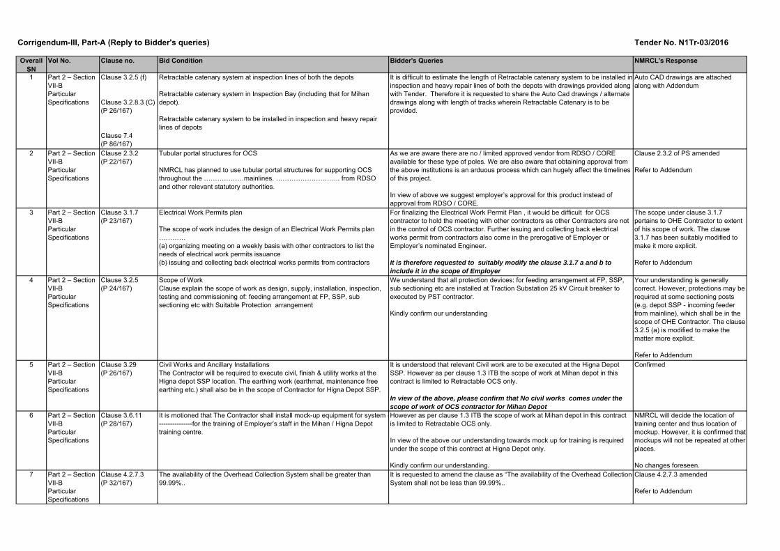
70 Part 2 Section VII-B
7.5.1.2 Contractor’s Agreement with Structure Manufacturers
Contractor shall have the technical and manufacturing support of a reputed international manufacturer of utility poles. The manufacturer shall make a written agreement with the Contractor for providing design and manufacturing support for the project. The manufacturer shall also be able to undertake the assembly and erection of structures at site or provide installation supervision at site. Copy of the agreement shall be submitted.
In case the structure manufacturer with whom the contractor makes agreement for design and supply is a multinational company, they should have a registered subsidiary company in India for their Indian operations. They should also have production facilities in India for manufacturing for this requirement. Proof of this shall be submitted.
The Indian subsidiary should also have facility for providing after sale supports to the contractor / Employer in India
71 Part 2 Section VII-B
7.5.1.3 The manufacturer with whom the Contractor makes an agreement shall have a minimum international experience of 10 years in design, manufacturing and supply of utility structures.
The manufacturer shall have to submit proof of his experience in design, manufacture and supply of utility poles in terms of purchase orders or completion certificates. Such certificates shall be submitted along with the agreement with the Contractor also.
The manufacturer should also have conducted 4 full-scale testing of poles in NABL accredited independent lab in past 4 years. Copies of previous test reports for such poles shall be submitted.
72 Part 2 Section VII-B
2.1.67.4
Retractable catenary system (with rigid OCS) have been planned in inspection and heavy repairs shed of both the depots.
Retractable catenary system to be installed in inspection and heavy repair lines of depots shall comprise of Rigid Overhead Contact System (ROCS).
We request NMRCL to provide the track length & number of the Inspection line and heavy repair line of Mihan Depot and Higna depot where Retractable catenary system has to be installed.
Confirmed
73 Part 1 Section IV Appendix H, Section EWD, Cost Center E
E2 Delivery of equipment for the Rigid OCS, Earthing & Bonding including thermosetting weld & cables, Earth Wire etc. of retractablecatenary works at Contractor’s premises in Nagpur:
E2.1 - 0.5 km for Mihan DepotE2.2 - 0.5 km for Higna Depot
Note: Please note that the prices are to be quoted for quantity mentioned above (total length) of retractable catenary works. In case of variation in the quantity the same shall be payable on pro-rata basis as per quoted price.
We understand that the indicated length of 0.5 Km for Mihan Depot and 0.5 Km for Higna Depot is cumulative length of Inspection and heavy repair line. Also the prorata shall be applied on per meter basis.
Kindly confirm our understanding.
Confirmed
74 Part 1 Section VII-C
Tender drawing MIHAN DEPOT LAYOUT - NMRCL/PLN/A/N-S/DL/MIHAN/2016/01HINGNA DEPOT LAYOUT - NMRCL/PLN/A/E-W/UP/HINGNA/2016/00
We request NMRCL to provide autocad drawings of the depot layout Auto CAD drawings are attached along with Addendum
We request NMRCL to kindly confirm that the requirement of Contractor's Agreement with structure manaufacture has to be carried our during execution stage.
We also request NMRCL to allow the contractor to execute the project with conventional RDSO approved B-Series & BFB structures which are proven in other metro projects which can be procured in India
Kindly consider our request to remove requirement of tubular poles for the project.
Refer to SN 18 above

Overall SN
Vol No. Clause no. Bid Condition Bidder's Queries NMRCL's Response
75 Part 2 Section VII-B
Part 1 Section IV
9.4.3
Appendix I, Cost Center E, Section MS
The Deployment of the Maintenance/Planning Experts and Technical Maintenance Experts may not be continuous and they may be required to supervise the maintenance in short periods at a time as required by the Employer/Employer’s Representative.
The deployment of the experts under this Cost Centre may not be continuous and they may be required to supervise the maintenance in short periods at a time. The number of man months of experts shall, however, not exceed 40 man-months. Payment for this Cost Centre will be made on man months basis.
The clause states that "The Deployment of the Maintenance / Planning Experts and Technical Maintenance Experts may not be continuous and they may be required to supervise the maintenance in short periods at a time as required by the Employer/Employer’s Representative."
From the above clause we understand that Employer may ask contractor for utilizing of man months in part and in different duration from issuance of the completion certificate of works of Reach 1 Section to the end of the DLP of last Reach. The same may lead to mobilization and demobilization of manpower as per utilization requirement by the employer, which is not feasible.
For instance, Cost center E requires 40 man months for maintenance, however from the man months it is not clear as to how many staff are required to be mobilized and for what duration. Let us assume the distribution of 40 man months as follows:
M1 - 2 staff; M2 - 1 staff; M3 - 2 staff; M4 - 0 staff; M5 - 1 staff; M6 - 2 staff.....M23 - 2 staff; M24 - 1 staff; M25 - 2 staff.....M 40 - 2 staff; M 41 - 2 staff; M 42 - 1 staff; M 43 - 2 staff
Total man months - 40
In reality, to meet the above requirement, the contractor needs to mobilize 2 staff for 43 months. The same may lead to cost of total man month of 2 x 43 = 86 , however as per the contract, the contractor shall be paid for 40 man months only leading to loss of 86 - 40 = 46 man months.
Hence to reduce the expected loss of man moths, we request you to kindly modify the Maintenance clause indicating the number of staff to be mobilized and the continuous duration of deployment.
NMRCL will be reasonable while operating the contract.
No changes foreseen
76 Part 2 Section VII-B
3.2.8.4 Regulated OHE with 5-pulley type ATD (80% of total) and spring type ATD (20% of total) on viaduct and unregulated OHE in depot
We understand that Entire depot cannot comprise of unregulated OHE.
Kindly confirm our understanding.
Confirmed
77 Part 2 Section VII-B
6.5.8.2.5.3 Concrete Poles shall be grouted with dry sand and the core hole after sand grouting shall be sealed with a 10cm layer of Bitumen before Muffing is provided to prevent any ingress of water in to the Core hole.
Kindly clarify the application / usage of concrete poles. Clause 6.5.8.2.5.3 deleted
Refer to addendum78 Part 2 Section
VII-B7.2.11 Modular Cantilever System (MCS) as per RDSO Specification no.
TI/SPC/OHE/MCS/0150 (08/2015) shall be provided for mainlines and test tracks in depot. For other tracks in depot, conventional proven cantilever arrangement may be provided.
There are no suppliers approved by RDSO for the given specification. We request NMRCL to allow equivalent EN & other standards to be applicable.
Kindly confirm.
Confirmed
79 Part 2 Section VII-B
7.3.2.1 25 kV Traction cables are mainly required for the following connections:(a) 25 kV cable feeder from outgoing switchgear at TSSs to OHE pole-mounted isolator on viaduct,
We request NMRCL to provide the route length of 25 kv cable from TSS location to Feeding post.
Exact layout of RSS at the proposed site of Morris College ground is not available right now. The OCS contractor may therefore make their own assesment of length of cables required for taking 4nos. of cables each for both corridors at nearest IOL(Feeding) location.

Overall SN
Vol No. Clause no. Bid Condition Bidder's Queries NMRCL's Response
80 General Progress of civil works in the Priority section. i) We understand that civil works for the elevated section has already been started and OHE Parapet locations have been finalized. In this regard, request you to please furnish the drawings of the girders showing the location of OHE parapets.
ii) Also, if you have decided to go ahead with pre-decided spacing of OHE parapet through out the corridor then please let us know the details & spacing of OHE parapet chainages.
The civil work of viaduct may already have started by the time the OCS contractor comes on board. In the existing design of viaduct "the OHE parapet locations" are provided only on both the end segments of viaduct girder (The viaduct general arrangement drawing is attached and the same is to be considered as part of tender drawings).The viaduct girders are going to have different span lengths ranging from 16.5 m to 54 m.While attempt shall be made to use the end segment of a span (having wider parapet) for installation of OHE support structure to the maximum extent, the Contractor may be required to make use of brackets / base plates at any other portion of viaduct similar to the arrangement shown in the drawing.
81 Part 1 Section IV Vendor approval and Selection Procedure for Design and Build Contracts
Manufacturer shall have at least 5 years experience of design and manufacturing of similar system. Proposed systems from the proposed manufacturing unit shall have been in use and have established their satisfactory performance and reliability for 2 years in minimum (either in India or in minimum two other countries).
We request you to reword the clause as:
Manufacturer shall have at least 3 years experience of design and manufacturing of similar system. Proposed systems from the proposed manufacturing unit shall have been in use and have established their satisfactory performance and reliability for 2 years in minimum (either in India or other country).
Refer to Addendum
82 Part 1, Page 31 ITB 4.1 & BDS Maximum number of members in the JV shall be: No LimitLead member must have a minimum of 40% participation in the JV / Consortium
Each member shall have minimum 25% participation.
Members having less than 25% participation will be termed as non- substantial member and will not be considered for evaluation.
In case of JV / Consortium, change in constitution or percentage participation shall not be permitted at any stage after their submission ofBid otherwise the Bidder shall be treated as non-responsive.
OHE works in this contract is a complete split from Power Supply works. Majority of the scope in OHE works are towards indigenized Supply items and constitutes small packages in sizes of 10% .It will be difficult to offload 25% participation to an individual member in this contract.
In view of the above, it is requested to reduce the % participation of each member to 10% from the existing 25% .
Tender Conditions Prevail
83 Particular SpecificationsPage 81/167
Clause 7.2.9.1 Flexible droppers, made of bronze, consisting of 1 wire of 7 strands each of 0.65 mm diameter and 6 wires of 7 strands each of 0.54 mm diameter, with crimped endings with eye on either end and reinforced automatic clamps (copper alloy made) on messenger wire and contact wire, are used as in-span droppers. The nominal cross sectional area of the droppers is 12 sq.mm and the diameter is 5 mm.
There are other suitable current carrying droppers (with 10 sq mm wire) which are globally in use as per EN specifications 50119Since the contract being design and built , we request you to open up the specifications as under
The nominal cross sectional area of the current carrying droppers shall be minimum 10 sq.mm.
Clause 7.2.9.1 amended
Refer to Addendum
84 Particular SpecificationsPage 142 of 167
Clause 11.2.1.3 Contractor shall also ensure that CMV is maintained in good working condition all the time and to ensure that keep all spares and T&P in accordance to the List as per Table 11.2. Maintenance of CMV is to be done by designated contractor. Contractor shall also maintain records for maintenance of Emergency vehicle and CMV.
We understand that supply of CMV is not in the scope of work of the contractor.
In view of above, we request you to remove the responsibility of maintaining the CMV from the scope of work of contractor by suitably amending this clause.
Clause 11.2.1.3 amended
Refer to Addendum
Overall SN
Vol No. Clause no. Bid Condition Bidder's Queries NMRCL's Response
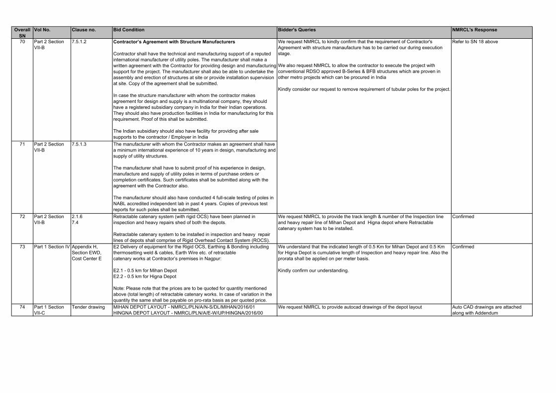
85 Particular SpecificationsPage 24 of 167
Clause 3.2.5 (d) Sub-sectioning arrangement (@every 2- 2.5km) with suitable protectionDrawing No NMRP/LIPL/EL/OHE /003 REV R0 sheet No – 01
Sub sectioning requirements are in contradiction between the drawing No NMRP/LIPL/EL/OHE /003 REV R0 sheet No – 01 and as per clause 3.2.5 (d).
It is requested to clarify the actual requirement of Sub- sectioning arrangement to be considered.
Refer to Note no. 3 of Sectioning diagram, which is in harmony with PS Clause 3.2.5 (d).
For avoidance of doubt, it is clarified that sub-sectioning shall be planned @2-2.5km.
86 Part 3, Page189 Additional Clause: Limit of Aggregate Damages on Employer
Notwithstanding anything to the contrary contained in the General Conditions of Contract, the Parties expressly agree that the aggregate “payment of any Cost plus profit” (“Damages”) payable under Clauses 1.9, 2.1, 4.7, 7.4, 10.2, 10.3 and 16.1 shall not exceed 10% (ten per cent) of the Contract Price. For the avoidance of doubt, the Damages payable by the Employer under the aforesaid Clauses shall not be additive if they arise concurrently from more than one cause but relate to the same part of the Project.
In the event of delays for reasons not attributable to the contractor, the Contractor should be eligible for payments of costs & profits at actual- meaning the payment should be accordance of the damage/loss suffered by the Contractor.
Limiting the aggregate damages on Employer to 10% doesn’t compensate the contractor at actual.
In view of the above it is requested to delete the limit of 10% from this clause.
Tender conditions prevail
87 Part 3, page 132 PC
Table: Summary of Sections (KEY DATES / ACCESS DATES)
KD-10 (Taking over of the System): R1-94 weeks; R2-142 weeks
ROD: R1-April 2018, R2-April 2019
KD-10 for R1 (which is 94 weeks from commencement of works) is a moving target, where as ROD for R1 indicated as Apr-18 will be a firm /fixed Target.
To achieve the indicated ROD duly considering KD 10 together, this contract should have been in place in June 2016.
Since there is a mismatch in the above it is requested to amend the Key Dates along with ROD suitably.
Refer to SN 68 above
88 Part 1, Section II ITB 19.1 A Bid Security is required as mentioned below:(a) Rs. 8.0 million (Eight Million Four Hundred Thousand INR) in form of unconditioned guarantee issued by any Nationalized or Scheduled Commercial Bank (including scheduled commercial foreign bank) inIndia. In the form of Bid Security as per Form 6 in Section-IV: Bidding Forms.
Kindly clarify wether the Bid security Amount is INR 8.0 Million or INR 8.4 Million Bid Security amount is INR 8.0 Million
Refer to Addendum

Corrigendum-III, Part-B (Addendum)
SN Part No.
Section Clause ref. Existing description Replaced with
1. Part 1 Section II ITB 19.1 A Bid Security is required as mentioned below: (a) Rs. 8.0 million (Eight Million Four Hundred Thousand INR) in form of unconditioned guarantee issued by any Nationalized or Scheduled Commercial Bank (including scheduled commercial foreign bank) in India. In the form of Bid Security as per Form 6 in Section-IV: Bidding Forms.
A Bid Security is required as mentioned below: (a) Rs. 8.0 million (Eight Million INR) in form of unconditioned guarantee issued by any Nationalized or Scheduled Commercial Bank (including scheduled commercial foreign bank) in India. In the form of Bid Security as per Form 6 in Section-IV: Bidding Forms.
2. Part 1 Section IV. Bidding Forms
Form 4.4 Bidder’s Technical Proposal; Para F.2
The System, including all Sub-systems and Equipment shall be of proven design practice. Sub-systems and Equipment of similar design philosophy shall have been in use and have established their performance reliability on at least one Mass Rapid Transit System or Suburban Railway System in Revenue Service over a period of at least two years (either in India or in minimum two other countries). Bidders are required to submit Performance certificates from users in support of the above performance requirements.
The System, including all Sub-systems and Equipment shall be of proven design practice. Sub-systems and Equipment of similar design philosophy shall have been in use and have established their performance reliability. Bidders are required to submit Performance certificates from users in support of the above performance requirements.
3. Part 1 Section IV; Annexure IV-A Pricing Document
Appendix I: Section MS; Cost Center D (Spares, Special Tools, Testing Equipment and Measuring Instruments)
New note inserted Note: As for the spares are concerned, the items already covered in Appendix J need not be included in the above. Spares, other than mentioned in Appendix J (ADJ: Adjustment / Unit Prices) may be suitably detailed and covered in the above Cost Centre D. Further, in the Appendix J, the total quantity indicated may be appropriately bifurcated by Bidders in two parts viz. for Reach 1 & 3 and Reach 2 & 4.
4. Part 1 Section IV, Annexure IV-A: Pricing Document
Appendix J, Item 34 ‘Description’
Complete set of fittings including bracket tube, stay tube, register arm, steady arm, registration
Complete set of fittings including bracket tube, stay tube, register arm, steady arm, registration (pull-off)
5. Part 1 Section IV, Annexure IV-
Appendix J, Item 35
Complete set of fittings including bracket tube, stay tube, register arm, steady arm, registration
Complete set of fittings including bracket tube, stay tube, register arm, steady arm, registration (push-off)

SN Part No.
Section Clause ref. Existing description Replaced with
A: Pricing Document
‘Description’
6. Part 1 Section IV; Annexure IV-A Pricing Document
Appendix M (Vendor Approval …) Para (3) under ‘Systems and Subsystems’
Proposed Systems/ sub-systems shall have been in use and have established their satisfactory performance and reliability on at least Two mass rapid transit systems (including Railway or Airports) in revenue service over a period of two years or more (either in India or in minimum two other countries). Systems/ Sub-systems/ components used in Indian metros do not get automatically qualified for use unless specifically approved by the Engineer for this project. If required by the Engineer, Contractor shall provide certificate of satisfactory performance for a period of two years or more from the Metro operators. Where similar System/ Sub-systems of a different rating are already proven in service as per the above criteria then the supply shall be based on such sub-systems.
Proposed Systems/ sub-systems shall have been in use and have established their satisfactory performance and reliability either on (i) at least one Mass Rapid Transit System or Suburban Railway System (including Railway or Airports) in Revenue Service over a period of at least two years in India; or (ii) at least two Mass Rapid Transit System or Suburban Railway System (including Railway or Airports) in Revenue Service over a period of at least two years in minimum two other countries. Systems/ Sub-systems/ components used in Indian metros do not get automatically qualified for use unless specifically approved by the Engineer for this project. If required by the Engineer, Contractor shall provide certificate of satisfactory performance for a period of two years or more from the Metro operators. Where similar System/ Sub-systems of a different rating are already proven in service as per the above criteria then the supply shall be based on such sub-systems.
7. Part 2 Section VII-A PS)
2.3 IT Requirements of Employer All the sub-clauses of Clause 2.3 stands replaced (refer below)
8. Part 2 Section VII-B (PS)
2.3.2 Tubular portal structures for OCS NMRCL has planned to use tubular portal structures for supporting OCS throughout the mainlines. Since such structures will be used first time in India, the Contractor shall duly consider the timely designs of the same including obtaining approvals from RDSO and other relevant statutory authorities.
Tubular portal structures for OCS NMRCL has planned to use tubular portal structures for supporting OCS throughout the mainlines. Since such structures will be used first time in India, the Contractor shall duly consider the timely designs of the same including drafting / preparing all relevant documents for obtaining approvals from RDSO and other relevant statutory authorities. NMRCL will proactively facilitate RDSO / Statutory approval process.
9. Part 2 Section VII-B 3.1.7 The scope of work includes the design of an Electrical The scope of work includes the design of an Electrical

SN Part No.
Section Clause ref. Existing description Replaced with
(PS) Work Permits plan and the management of the Electrical Work Permits on site, including:
Work Permits plan and the management of the Electrical Work Permits on site (relevant to OHE and switching stations i.e. for the scope under purview of OHE Contractor), including:
10. Part 2 Section VII-B (PS)
3.2.5 (a) Feeding arrangements to the overhead contact system with suitable protection at feeding post
Feeding arrangements to the overhead contact system with suitable protection at feeding post. (Protection relays required at TSS end are under scope of other contractor, while other protection relays at FP, SP, SSP etc. if foreseen, shall be under the scope of OHE Contractor. E.g. incoming feeder to Depot SSP may be required to be provided with Circuit Breaker and not Interrupter; however the final scheme shall be as per design of the Contractor.)
11. Part 2 Section VII-B (PS)
3.2.8.4 (n) Regulated OHE with 5-pulley type ATD (80% of total) and spring type ATD (20% of total) on viaduct and unregulated OHE in depot
Regulated OHE with spring type ATDs on viaduct and unregulated OHE in depot
12. Part 2 Section VII-B (PS)
4.2.7.3 The availability of the Overhead Collection System shall be greater than 99.99%.
The availability of the Overhead Collection System shall not be less than 99.99%.
13. Part 2 Section VII-B (PS)
4.4.4.2 The traction system shall be able to allow the degraded operation in 2041, as per Operation Plan under the following degraded modes: one out of the two TSS is out of order.
The traction system shall be able to allow the normal operation in 2041, as per Operation Plan under the following degraded modes: one out of the two TSS is out of order.
14. Part 2 Section VII-B (PS)
6.4.5.1.4 The interrupters and isolators meant for sectioning shall be located in the station area in a room close to the sections required to reduce length of cables.
The interrupters and isolators meant for sectioning shall be located near the station area generally structure mounted on viaduct close to the sections required to reduce length of cables.
15. Part 2 Section VII-B (PS)
6.5.8.2.5.3 Concrete Poles shall be grouted with dry sand and the core hole after sand grouting shall be sealed with a 10cm layer of Bitumen before Muffing is provided to prevent any ingress of water in to the Core hole.
Deleted
16. Part 2 Section VII-B (PS)
7.2.2.2 The Contractor shall adopt the following types of mast of various sizes of H type mast for main line:
The Contractor shall adopt various sizes of H type masts at following locations:
17. Part 2 Section VII-B (PS)
7.2.9.1 Flexible droppers, made of bronze, consisting of 1 wire of 7 strands each of 0.65 mm diameter and 6 wires of 7
Flexible droppers, made of bronze, consisting of 1 wire of 7 strands each of 0.65 mm diameter and 6 wires of 7

SN Part No.
Section Clause ref. Existing description Replaced with
strands each of 0.54 mm diameter, with crimped endings with eye on either end and reinforced automatic clamps (copper alloy made) on messenger wire and contact wire, are used as in-span droppers. The nominal cross sectional area of the droppers is 12 sq.mm and the diameter is 5 mm.
strands each of 0.54 mm diameter, with crimped endings with eye on either end and reinforced automatic clamps (copper alloy made) on messenger wire and contact wire, are used as in-span droppers. The nominal cross sectional area of the droppers is 12 sq.mm and the diameter is 5 mm. Alternate specifications of droppers with different cross-section (less or more) may be considered subject to compliance of the same with EN 50119 (or equivalent other standards), their proven-ness in other metro / railway systems and subject to the overall designs meeting all functional and specified requirements.
18. Part 2 Section VIIB Particular Specification
7.2.11 Cantilever Assemblies
Modular Cantilever System (MCS) as per RDSO Specification no. TI/SPC/OHE/MCS/0150 (08/2015) shall be provided for mainlines and test tracks in depot. For other tracks in depot, conventional proven cantilever arrangement may be provided.
Modular Cantilever System (MCS) shall be generally as per RDSO Specification no. TI/SPC/OHE/MCS/0150 (08/2015) with tubes of “Hot dip galvanized steel” for mainlines and test tracks in depot. For other tracks in depot, conventional proven cantilever arrangement may be provided.
19. Part 2 Section VII-B (PS)
7.2.14.1 5-pulley type automatic tensioning devices along with protective cage (for weights) shall be provided for about 80% of the requirements. The devices shall be as per general arrangement indicated in the Tender Drawings.
Deleted
20. Part 2 Section VII-B (PS)
7.2.14.2 For remaining 20% of the requirements, Spring Auto Tensioning Device as per RDSO Specification no. TI/SPC/OHE/SPRING ATD/0110 (03/2012) shall be provided.
For all the requirements on mainlines and depots, Spring Auto Tensioning Device as per RDSO Specification no. TI/SPC/OHE/SPRING ATD/0110 (03/2012) or better shall be provided.
21. Part 2 Section VII-B (PS)
7.4.3.9 Conductor rail shall be of Aluminium alloy section with wearing copper contact wire. The conductor rail shall have anti-corrosion treatment on its surface. Sections of transportable lengths will be joined together to form lengths up to 250m between expansion joints. The Contractor shall furnish the merits of the conductor rail system offered indicating the life, speed potential of
Conductor rail shall be of Aluminium alloy section with wearing copper contact wire. The conductor rail shall have anti-corrosion treatment on its surface. Sections of transportable lengths will be joined together to form lengths up to 250m between expansion joints. The Contractor shall furnish the merits of the conductor rail system offered indicating the life, speed potential of

SN Part No.
Section Clause ref. Existing description Replaced with
installation, strength and conductivity of joints, maintainability and the supporting details including performance of similar rigid conductor systems if provided by him on any other metros system. Contact Wire shall be Round Bottom, 150 sq mm area and shall comply with EN 50149. Contact wire shall be made from Continuous Cast Copper (CCC) rod of minimum 21 mm diameter as per RDSO Specification. Also, Contact wire shall be hard Drawn Grooved Copper Contact Wire complying to RDSO standard ETI/OHE/76 (6/97).
installation, strength and conductivity of joints, maintainability and the supporting details including performance of similar rigid conductor systems if provided by him on any other metros system. Contact Wire shall be Round or Flat Bottom, 150 sq mm area and shall comply with EN 50149. Contact wire shall be made from Continuous Cast Copper (CCC) rod of minimum 21 mm diameter as per RDSO Specification. Also, Contact wire shall be hard Drawn Grooved Copper Contact Wire complying to RDSO standard ETI/OHE/76 (6/97).
22. Part 2 Section VII-B (PS)
7.5.1.2 Contractor’s Agreement with Structure Manufacturers Contractor shall have the technical and manufacturing support of a reputed international manufacturer of utility poles. The manufacturer shall make a written agreement with the Contractor for providing design and manufacturing support for the project. The manufacturer shall also be able to undertake the assembly and erection of structures at site or provide installation supervision at site. Copy of the agreement shall be submitted. In case the structure manufacturer with whom the contractor makes agreement for design and supply is a multinational company, they should have a registered subsidiary company in India for their Indian operations. They should also have production facilities in India for manufacturing for this requirement. Proof of this shall be submitted. The Indian subsidiary should also have facility for providing after sale supports to the contractor / Employer in India.
Contractor’s Agreement with Structure Manufacturers Contractor shall have the technical and manufacturing support of a reputed international manufacturer of utility poles. The manufacturer shall make a written agreement with the Contractor for providing design and manufacturing support for the project. The manufacturer shall also be able to undertake the assembly and erection of structures at site or provide installation supervision at site. Copy of the agreement shall be submitted. In case the structure manufacturer with whom the contractor makes agreement for design and supply is a multinational company, they should have a registered subsidiary company in India for their Indian operations. They should also have production facilities (including galvanization facility) in India for manufacturing for this requirement. Proof of this shall be submitted. The Indian subsidiary should also have facility for providing after sale supports to the contractor / Employer in India.

SN Part No.
Section Clause ref. Existing description Replaced with
23. Part 2 Section VII-B (PS)
7.5.1.3 Tubular Structure Manufacturer’s Experience The manufacturer with whom the Contractor makes an agreement shall have a minimum international experience of 10 years in design, manufacturing and supply of utility structures. The manufacturer shall have to submit proof of his experience in design, manufacture and supply of utility poles in terms of purchase orders or completion certificates. Such certificates shall be submitted along with the agreement with the Contractor also. The manufacturer should also have conducted 4 full-scale testing of poles in NABL accredited independent lab in past 4 years. Copies of previous test reports for such poles shall be submitted.
Tubular Structure Manufacturer’s Experience The manufacturer with whom the Contractor makes an agreement shall have a minimum international experience of 5 years in design, manufacturing and supply of utility structures. The manufacturer shall have to submit proof of his experience in design, manufacture and supply of utility poles in terms of purchase orders or completion certificates. Such certificates shall be submitted along with the agreement with the Contractor also. The manufacturer should also have conducted 4 full-scale testing of poles in NABL accredited independent lab in past 4 years. Copies of previous test reports for such poles shall be submitted.
24. Part 2 Section VII-B (PS)
7.5.3.1.1 4th Para
Structures shall be designed so that member unit stress does not exceed the yield point stress of the material. The ratio of major axis of tubular diameter to wall thickness shall be such that local buckling does not govern member design. Structure deflection under maximum load condition including over load factors shall be no more than 1.5 % of the structure height.
Structures shall be designed so that member unit stress does not exceed the yield point stress of the material. The ratio of major axis of tubular diameter to wall thickness shall be such that local buckling does not govern member design. Structure deflection under maximum load condition including over load factors shall be no more than 1.5 % of the structure height or 80mm (at the tip of the structure for permanent loads and at the contact wire level for wind loads) whichever is less.
25. Part 2 Section VII-B (PS)
10.2.7 The initial contract spares list shall cover the items as per Appendix M of Pricing Document.
The initial contract spares list shall cover the items as per Appendix J of Pricing Document.
26. Part 2 Section VII-B (PS)
11.2.1.3 Contractor shall also ensure that CMV is maintained in good working condition all the time and to ensure that keep all spares and T&P in accordance to the List as per Table 11.2. Maintenance of CMV is to be done by designated contractor. Contractor shall also maintain
Contractor shall also ensure that CMV is maintained in good working condition all the time and to ensure that keep all spares and T&P in accordance to the List as per Table 11.2. Maintenance of CMV is to be done by designated contractor. Contractor shall also maintain

SN Part No.
Section Clause ref. Existing description Replaced with
records for maintenance of Emergency vehicle and CMV.
records for maintenance of Emergency vehicle and CMV. Provision of this clause in respect of CMV maintenance will be applicable only in case CMV supply is in scope of OHE Contractor. Wiring should be done by RRV/ wiring train/CMV, manual wiring will damage the OHE wires
27. Part 2 Section VII-B (PS), Appendix A: Interfaces
Table 3.2, Item 3 & 4 (Interface with PS Contractor)
SN
By PST Contractor
By OCS Contractor
Location
Purpose of
Interface
3 Shall provide the SCADA equipment including battery control supply at SP / SSP / SS for mainlines and depots Shall supply and provide connection between SP / SSP / SS and SCADA RTU
Shall coordinate with PST Contractor and make provisions of adequate number of potential free contacts on equipment and connection arrangement
SP / SSP / SS at Mainline and depot
SCADA system
4 Shall coordinate with cooperate with OCS Contractor and make appropriate arrangement of cable termination arrangement at FP (GIS type) end to enable OCS contractor to connect cables at 25kV GIS switchgears
Shall supply and install 25kV and return cables between Feeding Posts at Sitabuldi and OCS (both NS and EW corridors)
FP / SP 25kV and return cables connections
SN
By PST Contractor
By OCS Contractor
Location
Purpose of
Interface
3 Shall provide the SCADA equipment including battery control supply at SP / SSP / SS for mainlines and depots Shall terminate the control / SCADA cables from SS/SSP at RTU end
Shall coordinate with PST Contractor and make provisions of adequate number of potential free contacts on equipment and connection arrangement Shall supply and provide connection / cables between SP / SSP / SS (and 5MVA TSS at Mihan Depot) and SCADA RTU
SP / SSP / SS at Mainline and depot
SCADA system
4 Shall coordinate with cooperate with OCS Contractor and make appropriate arrangement of cable termination
Shall supply and install 25kV and return cables between Feeding Posts at Sitabuldi and TSS (both NS and EW corridors)
FP / TSS
25kV and return cables connections
SN Part No.
Section Clause ref. Existing description Replaced with
arrangement at TSS (GIS type) end to enable OCS contractor to connect cables at 25kV GIS switchgears
28. Part 2 Section VII-B (PS), Appendix B: Technical Sheets
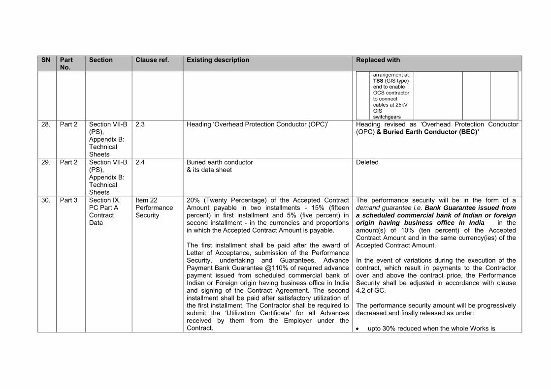
2.3 Heading ‘Overhead Protection Conductor (OPC)’ Heading revised as ‘Overhead Protection Conductor (OPC) & Buried Earth Conductor (BEC)’
29. Part 2 Section VII-B (PS), Appendix B: Technical Sheets
2.4 Buried earth conductor & its data sheet
Deleted
30. Part 3 Section IX. PC Part A Contract Data
Item 22 Performance Security
20% (Twenty Percentage) of the Accepted Contract Amount payable in two installments - 15% (fifteen percent) in first installment and 5% (five percent) in second installment - in the currencies and proportions in which the Accepted Contract Amount is payable. The first installment shall be paid after the award of Letter of Acceptance, submission of the Performance Security, undertaking and Guarantees, Advance Payment Bank Guarantee @110% of required advance payment issued from scheduled commercial bank of Indian or Foreign origin having business office in India and signing of the Contract Agreement. The second installment shall be paid after satisfactory utilization of the first installment. The Contractor shall be required to submit the ‘Utilization Certificate’ for all Advances received by them from the Employer under the Contract.
The performance security will be in the form of a demand guarantee i.e. Bank Guarantee issued from a scheduled commercial bank of Indian or foreign origin having business office in India in the amount(s) of 10% (ten percent) of the Accepted Contract Amount and in the same currency(ies) of the Accepted Contract Amount. In the event of variations during the execution of the contract, which result in payments to the Contractor over and above the contract price, the Performance Security shall be adjusted in accordance with clause 4.2 of GC. The performance security amount will be progressively decreased and finally released as under: upto 30% reduced when the whole Works is

SN Part No.
Section Clause ref. Existing description Replaced with
commissioned (it will be applied in two stage i.e. 15% when Reach 1 / Reach 3 are commissioned and remaining 15% when Reach 2 / Reach 4 are commissioned)
a further 30% reduced by end of 50% of DLP period i.e. 12 months from the date of issue of Taking Over Certificate for whole works
the balance 40% shall be released as provided for in PC Clause 4.2
31. Part 3 Section IX. PC Part B
SN 2 (Sub-Clause 4.2A)
New note is added at the bottom of the clause Note: The Parent Company Undertaking and Parent Company Guarantee shall not be necessary in the case of the Bidder is not using experience / credentials of Parent Company (Associate / Affiliate) for the purpose of qualifying requirements (as per Section III. Eligibility and Qualification Criteria of Part 1).
32. Part 3 Section X, Contract Forms
Parent Company Undertaking (Para 1)
In consideration of the Employer entering into the Contract with the Contractor, the Parent Company hereby undertakes to the Employer that, without the written consent of the Employer, it will not [and will ensure that none of the companies referred to in Recital (C) will] [see Note 5]:
In consideration of the Employer entering into the Contract with the Contractor, the Parent Company hereby undertakes to the Employer that, without information to the Employer, it will not [and will ensure that none of the companies referred to in Recital (C) will] [see Note 5]:
33. Part 2 Particular Specification Appendix F
4 The Firm to be engaged for this Design work shall meet the following criteria:
Should have experience of preliminary design, detailed design or design review of metro railway power supply and traction system for at least one metro project
Should have experience of preliminary design, detailed design or design review of at least 30 track kms. of 25 kV ac OHE works of metro railway or mainline railways
Should have experience of preliminary design, detailed design or design review of interfaces with civil works in at least one metro project
The Firm to be engaged for this Design work shall meet the following criteria:
Should have experience of preliminary design, detailed design or design review of metro railway power supply and traction system for at least two metro project
Should have experience of preliminary design, detailed design or design review of at least 100 track kms. of 25 kV ac OHE works of metro railway or mainline railways
Should have experience of preliminary design, detailed design or design review of interfaces with civil works in at least one metro project

SN Part No.
Section Clause ref. Existing description Replaced with
34. Part 1 Annexure-IV-A: Pricing Document Appendix- D to H
Cost Centre A: Detail Design A5
Validation / Auditing of Design and Installation of …………………………
Validation / Auditing of Design of ……………………… ……………………….
35. Part 2 Particular Specification
3.2.5 New Note inserted Note: With regards item (h) above, The viaduct girders are going to have different span lengths ranging from 16.5 m to 54 m. While attempt shall be made to use the end segment of a span (having wider parapet) for installation of OHE support structure to the maximum extent, the Contractor may be required to make use of brackets / base plates at any other portion of viaduct similar to the arrangement shown in the related tender drawing.
36. Part 1 Annexure-IV-A: Pricing Document Appendix – P: Vendor Approval and Selection Procedure
(8) New Note In respect of Tubular Portal, since the item is being provided for the first time in India so the criteria item no. (3) above is dispensed with.
37. Part 1 Section IV A Pricing Document
Appendix J New items added APPENDIX J: ADJ (ADDITIONAL / UNIT PRICES)
Item No.
Description Unit Qty Unit Rate
Total
FC
INR
FC
INR
Testing Items 76 CENTRIX for
132kV UG cable Fault location system
No 1
77 Digital Multimeter (AVO410 or equivalent)
No 2

SN Part No.
Section Clause ref. Existing description Replaced with
78 Digital Clamp Meter (DCM340 or equivalent)
No 2
79 Digital Earth Tester(DET4TCR2 or equivalent)
No 2
80 Digital Insulation Tester (1kV) MIT430 or equivalent
No 2
81 Digital Insulation Tester (5kV) BM5200 or equivalent
No 2
82 Digital low resistance Ohm meter (DLRO10X or equivalent)
No 1
83 Torkel (Battery Load Tester)
No 1
84 TRAX (Transformer & Substation Test set)
No 1
38. Part 1 Section II BDS
ITB 22.1 The deadline for bid submission is: Date: 23rd September 2016, Time: 16.00 Hrs
The deadline for bid submission is: Date: 06th October 2016, Time: 16.00 Hrs


Ref: Item No. 7 above
Part 2. Section VII A (GS) 2.3 IT Requirement of Employer
1.1.1 Employer is in the process of implementing an Enterprise wide IT system project titled “Digital Project Management Platform”. The objective of the IT project is to develop a working environment that enables higher efficiency and effectiveness, not only in internal functions, but also across the entire ecosystem of the Employer including Contractors. The IT project envisaged following application stack: (a) Collaborative document control and management services (using Bentley
ProjectWise and AssetWise solution) (b) Scheduling services (using Oracle Primavera P6 Enterprise Project Portfolio
Management (EPPM)) (c) Project Management with progress and performance reporting (using Primavera
P6 & Unifier solution) (d) Progress and performance reporting with visualization (using RIB iTWO ) (e) Enterprise wide ERP SAP implementation
1.1.2 The proposed IT system has been conceptualized for facilitating preservation of important artifacts (plans, drawings, notes, documents, reports etc.) in a secure and manageable environment in digitized format. Appropriate triggers shall generate dashboards and management reports every time an event causes a substantial shift in the project risk or a deviation in processes is developed. The envisaged system would expedite decision-making, ensure better planning and coordination between different functions, better data management, effective reporting, knowledge management etc. Program management shall provide senior management with critical information related to various contracts, activities and funds in the form of management dashboards with inbuilt triggers to ensure timely decision-making. Clause 1.1.6 details out the bidder’s expected involvement on NMRCL’s Digital platform
1.1.3 The effective use of such IT platform requires availability of system at all requisite locations i.e. with Employers’ various offices, Engineer’s offices, Contractors’ end, major sub-contractors’ end, design consultant ends etc. with certain definite users’ rights. Data uploading by various authorized and trained users is key to effective implementation of the IT system. It is expected that contractor would have previously worked on the similar packages also it is understood that such envisaged IT platform is already a part of detailed scope of work of successful bidder. However, NMRCL has conceptualized the creation of a 5D BIM platform which would be the single collaborative environment among all stakeholders including contractors, General consultants, detailed design consultants etc. for efficient & seamless flow of information.
1.1.4 In view of the above, the Contractor shall be required to:
(a) Follow and comply the system guidelines to be issued by Employer/GC (b) Comply all the software system competency. (c) Upload / definition of Project Plans as per the template and using software
defined by the Employer/GC; (d) Maintenance and updating of uploaded Project Plans in software used by the
Employer/GC; (e) Upload of drawings / designs created by the Contractor as per the classification
and on the software platform defined by the Employer/GC; (f) Key contract related communication and progress related data as per processes
defined on the software platform deployed by the Employer/GC

(g) Asset details need to be updated in the system in the format prescribed by the Employer/GC;
Bidder is expected to review section 2.3.6 for more details for bidder’s expected
involvement on NMRCL’s Digital platform
1.1.5 Employer and its IT Implementation Agency shall render necessary assistance for the training of contractor staff.
1.1.6 Bidder will need to be accessing NMRCL’s digital platform for at least the mentioned
functions as applicable as per bidder’s respective scope of work. However the function list is indicative and precise activities from bidder on NMRCL’s digital platform will be updated and communicated to bidder on time to time basis.
Following are the deliverables in form of collaboration with 5D BIM by Bidder:
1.1.6.1 Creation of 3D engineered intelligent Models using discipline specific modelling/engineering applications.
1.1.6.2 Creating 2D drawings in CAD – plan, section, elevation and other relevant details (based on specific engineering disciplines) to be accessed by the contractors for construction.
1.1.6.3 Bidder need to comply with the following requirements in regards to the production of all the CAD (3D/2D) data files and building information modeling (BIM) work.
1.1.6.3.1 Model file production principles
1) Bidder need to follow British Standard BS 1192:2007+A2:2016 for Collaborative production of architectural, engineering and construction information - Code of practice as a guide for drawing practice, convention, CAD data structure and translation.
2) Bidder need to model all design and construction information as an individual discipline model and then collaborate it in single master 3D composite model, using object based software, allowing for 2D models to be extracted as required.
3) Bidder need to create and share details of individual components of 3D models for each discipline involved.
4) Bidder need to share all individual discipline models as well the collaborated single master model through the Engineering Information Collaboration System for review by GC/NMRCL. Clash detection and resolution process will run in this composite area. All 3D model data together with all 2D drawing extractions needs to be spatially coordinated with the Geospatial System. UTM/WGS84 coordinate system needs to be followed for proper geo-referencing of all the engineered 3D models that will be created.
1.1.6.3.2 Model file composition
1) Bidder need to generate model files using seed files/template (2D and 3D). Seed files/template will standardize all the new drawings that one creates. It will standardize the same global origin, color table, cell library attachments, working units, views etc.
2) Model files needs to contain one model view and one sheet view
3) All graphical elements need to be placed in the model view
4) Model files need to have a title box placed in the sheet view
5) All model files need to be created at 1:1 scale

1.1.6.3.3 Model Outputs
1) Within the engineering collaboration system the central premise is that only approved data is shared. Each discipline WIP area can only reference data from the shared area i.e. approved data. When this data comes together in the composite model it can be fully coordinated and composite renditions can be produced in 3D.
1.1.6.3.4 Model Reviews
1) Bidder needs to ensure that the level of complexity and granularity for each discipline CAD model is appropriate for the stage of Works.
2) Bidder needs to ensure that all disciplines integrate and coordinate their outputs in terms of both spatial and functional provision. This shall be demonstrated through the extensive use of coordinated design review sessions which shall include for the coming together of all relevant discipline models into a common master model (model composite) where engineering assurance and coordination checks shall take place.
1.1.6.3.5 Existing Infrastructure data sets
1) Bidder need to model existing infrastructure and systems in sufficient detail as to provide integration with the works under contract
2) Bidder need to clearly highlight the unresolved areas of non-coordination in structure/services/finishes/clashes on the drawings and the model at all times in case of existing infrastructure data sets
3) Bidder need to report back to the owner any discrepancy with the existing data for their action
1.1.6.3.6 Coordination and integration – Drawing Packages
1 Within the BIM environment each of the disciplines need to reference other models in a timely manner for coordination purposes. The head of each discipline group shall decide the extent and nature of supporting discipline data that shall be displayed in each of their own discipline drawing submissions. Clash detection software routines needs to be run on the multi-discipline model and on combined master models and any clashes resolved. The reports of which will be submitted on request of the Engineer
2 Specific drawing packages are required from each discipline. The drawings need to comprise of 2D extractions of the 3D models from the engineering collaboration system.
3 All CAD drawings need to be comprised of 2D models extracted from the 3D master model. Any subsequent design scheme changes that are required to be fully coordinated shall be modeled in 3D and the drawing extraction re-run to produce revised plots.
4 All plot composition files need to be checked as prescribed by the workflow setup in the engineering collaboration system before submission to the Engineer.
1.1.6.4 The bidder shall take full advantage of the 3D object attributes available in the BIM environment to prove cost, constructional logic, fabrication, and program as required by the NMRCL/GC. Engagement modality expected for Project Management works including 4D & 5D BIM requirements: -
1. Bidder shall allocate a Project Coordinator who would be a single-point contact for NMRCL for monitoring day-to-day progress on the Project.
2. Bidder will access the web-based Project Monitoring application (Primavera) of

NMRCL
3. Bidder will have to create Work Breakdown Structure (WBS) for its scope of work in the master project prepared and released by NMRCL on Primavera.
4. Bidder will have to create all the relationships between various activities to generate a Critical Path Network on Primavera.
The project plan will be detailed to reflect the planned construction progress as per the 3D BIM model. This is must, as Primavera plan will get linked to 3D BIM collaborated intelligent model to reflect and review time based planned progress of project on a BIM model. Bidder’s project plan on NMRCL Primavera platform will be required at this level.
5. Once the network has been scheduled and baseline by NMRCL/GC, the Project Coordinator will have to provide periodical updates for various activities.
6. Bidder will also be required to furnish key cost / budget details along with resources on NMRCL’s Primavera platform. Level of details for time plan, cost, and resources from bidder will be communicated to bidder at appropriate stage.
7. During the execution stage bidder will be required to operate on NMRCL’s Primavera platform to reflect minimum details towards work performed, progress achieved, resources consumed, forecast dates, forecast resources, remaining work along with any other key details as Required by NMRCL / GC. NMRCL will be communicating on level of details as well frequency of such interactions at appropriate stage.
8. Bidder shall update and revise their work program on the integrated master schedule of the project subject to directions & approval from NMRCL.
9. Bidder will be required to periodically capture actual progress visualization of respective package work using suitable technology which can be updated in 5D BIM platform.
1.1.6.5 In order to adopt 5D BIM platform bidder need to follow Employer’s Information Requirement (EIR) Document which will be prepared by Owners Support Office (OSO) in consultation with General Consultant (GC) and handed over to the Bidder. The EIR will enlist the standards, methods and procedures that one has to follow in order to be BIM Compliant. EIR will have details such as CAD standards, BIM standards, Asset Dictionary, Asset Classes, file naming convention, layer naming convention, Attribute Standards, etc.
1.1.6.6 SAP ERP (Component of Digital Project Platform):
In order to adopt SAP ERP platform contractor will be required to follow Employer’s Information Requirement (EIR) Document which will be prepared by OSO in consultation with General Consultant (GC) and handed over to the contractor. The EIR will enlist the standards, methods, procedures and data related to defined functionality coverage in SAP ERP.
1.1.6.7 Minimum login credentials (as decided by NMRCL) per bidder will be provided by NMRCL to the bidder to access NMRCL digital platform as per clause 1.1.3. In case, bidder envisages more user licenses for their internal data preparation through their internal user (like detailed drawing or project plan preparation by multiple users) which is required for finalizing data to be entered in NMRCL’s digital platform, then it will be bidder’s responsibility to ensure own licenses. However the access to NMRCL’s digital platform will be through provided user credential only.
1.1.6.8 The engineering collaboration platform will be provided by NMRCL and is mandated for the structure and the controlled sharing of the information created during the process.

Ref: Item No. 38 above Tender No.(As Uploaded in the e-tender portal) 52
Event Date as per Bid Document (Corrigendum-II) Revised Dates
Last Date of Submission of bids. Till 16:00 hrs, dt.23.09.2016 Till 16:00 hrs, dt.06.10.2016
Date of Opening of Bids. At 16:30 hrs, dt.23.09.2016 At 16:30 hrs, dt.06.10.2016
General Manager (Procurement)
NMRCL, Nagpur