Corridor Modeling (7-1-2013) - Mississippisp.mdot.ms.gov/RoadwayDesign/CADD_Info/GeoPak Help...
18
Corridor Modeling (7-1-2013) OVERVIEW This is Bentley’s application which creates 3d models of highways. MDOT has created a library of templates which match our standards. C:\rwd\input\RWD.ITL is the file that contains MDOT’s template library. This file should be copied to each project directory and any templates created or modified should be created in the Project Specific folder in this file. This is discussed more in the Template Creation chapter. A Corridor is created on each given roadway with an established proposed profile. Template Drops are the type of template you wish to place on a Corridor for a given station range. BEST/REQ’D. PRACTICES 1. Separate Template Drops should be created for each area between bridges with each drop extending into the Bridge. This area will be clipped in the later stages. 2. Each Phase of Construction should be represented by a Corridor. This is not required if Sheet Piling is used with no temporary slopes. 3. Each alignment (ML, LR, Loop, Ramp, etc.) should be its own Corridor and genrally should be in its own file. Multiple Corridors for single roadways are acceptable and can be in one or multiple files. This is warranted with 4-lanes with meandering medians and also suggested for longer roadways to aid processing time. Suggested maximum length of a Corridor is 3 miles.
Transcript of Corridor Modeling (7-1-2013) - Mississippisp.mdot.ms.gov/RoadwayDesign/CADD_Info/GeoPak Help...
Corridor Modeling (7-1-2013)
OVERVIEW
This is Bentley’s application which creates 3d models of highways.
MDOT has created a library of templates which match our standards. C:\rwd\input\RWD.ITL is the file that contains MDOT’s template library. This file should be copied to each project directory and any templates created or modified should be created in the Project Specific folder in this file. This is discussed more in the Template Creation chapter.
A Corridor is created on each given roadway with an established proposed profile. Template Drops are the type of template you wish to place on a Corridor for a given station range.
BEST/REQ’D. PRACTICES 1. Separate Template Drops should be created for each area between bridges with each
drop extending into the Bridge. This area will be clipped in the later stages.
2. Each Phase of Construction should be represented by a Corridor. This is not required if Sheet Piling is used with no temporary slopes.
3. Each alignment (ML, LR, Loop, Ramp, etc.) should be its own Corridor and genrally should be in its own file. Multiple Corridors for single roadways are acceptable and can be in one or multiple files. This is warranted with 4-lanes with meandering medians and also suggested for longer roadways to aid processing time. Suggested maximum length of a Corridor is 3 miles.

4. Template Drop Increments – 10’ High Speed & 5’ low speed roadways req’d. Corridor Stage Phase “A” is set by default to 5 x INC. = 25’ sections, Phase “B” is set to 1 x INC. = 5’ sections.
5. Limit Clipping which causes processing overhead. Templates are set up to automatically turn off End Conditions & shoulders in intersection areas when the P-EP-INT lines placed with cells are added as External References.
6. AMG deliverables are discussed more in the “AMG Deliverables” section in this document.
WORKFLOW 1. Create Civil horizontal and vertical geometry element(s). This is done outside the
corridor modeling tools.
2. Set the active terrain (existing ground). Generally this will be a referenced file containing the Terrain or imported TIN.
3. Create a corridor based on a Civil horizontal and vertical elements.
4. Add template drop(s).
5. Add horizontal and/or vertical controls for particular points (optional).
6. Define any transitions and connect.
7. Associate superelevation information.
8. Review the results and make adjustments.
9. Add Civil Cells at Intersecting Roadways, X-Over’s, Bridges, etc.
10. Add External Constraints to drop End Conditions through Intersections/X-Overs.
CREATE CORRIDOR Once your alignment & profile is created, you can create a Corridor.
1. Create the file Corridor-*.dgn using a 2d seed file. (CORRIDOR-roadwayname-(phase)-(stationlimits).DGN
2. Reference in the file containing the existing terrain and make it active.
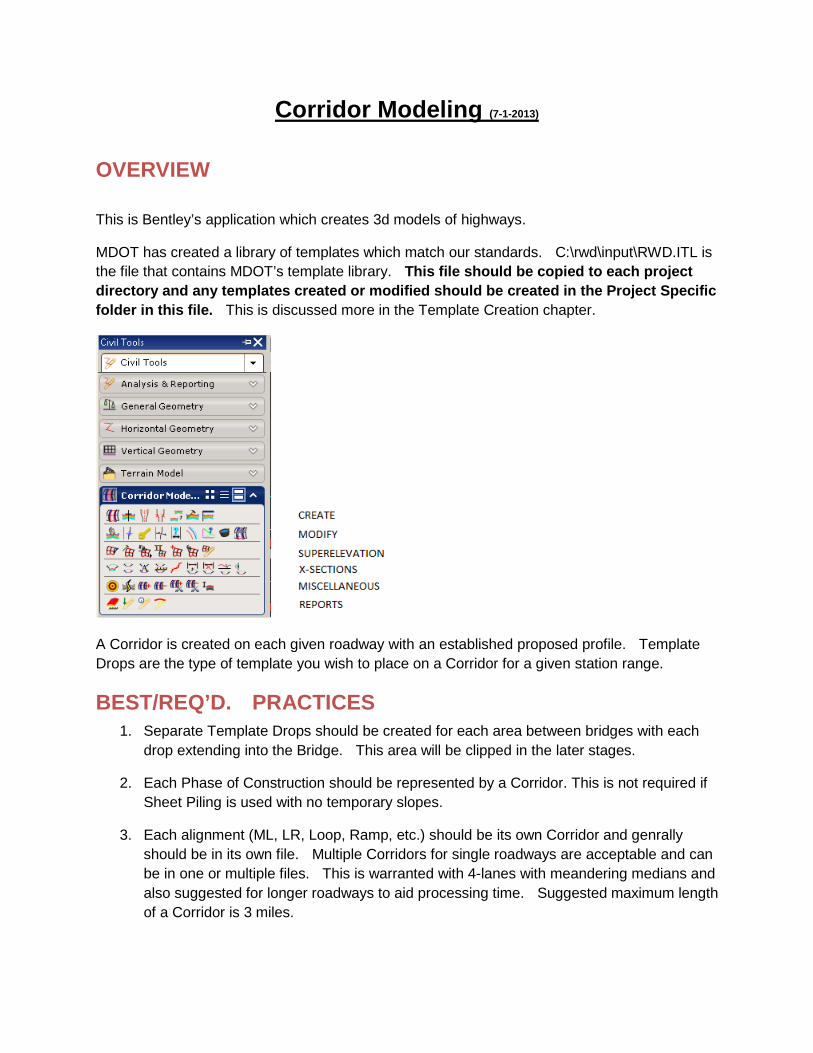
3. Open or Fit View 5 & open the Default-3d model.
4. Alignment DGN file (ALIGPK.DGN) is referenced to View 1 (Default model). Default-3d model should be referenced with this attachment.
5. Choose the Create Corridor command from the Corridor Modeling menu or the context menu by clicking the alignment.
or
6. You’re prompted with the following. Choose the profile or reset if you set the proposed profile as the active profile.
The Design stage can and will need to be changed later. Phase “A” will give you template drops 5x the template drop increment (normally 10’) you’ll specify on the next dialog. Phase B will give you sections 1x the template drop increment. Creating AMG deliverables (3d/Mesh phases) is discussed below.
7. You’re prompted with the Create Template Drop dialog. Choose the station range & template you want to drop.

8. Your model should be processed.
Note: The template dropped is as drawn in the template library. No Superelevation yet, possibly incorrect lane/shoulder widths, structure/pavement depth needs project specific adjustment, clear zone/ditch depth/fill slope/cut slope need adjustment, etc. The following steps show how to make these project specific adjustments.
CORRIDOR/TEMPLATE CONTEXT MENUS Context Menus leading to most of the commands available on the Civil MDOT menu are available by choosing the Template Drop or Corridor handlers shown below and then hovering your cursor over them. These handlers are construction elements.

CROSS-SECTION VIEW 1. Choose the following button to open a x-section view.
2. You should now have 4 views open.
3. Temporary Dimension Lines

4. Create X-Sections – Set up x-section sheets which is discussed in another chapter.
MODIFY CORRIDOR
The tools highlighted above are used for tying template points to graphical elements/profiles (point controls), defining project specific variables (parametric constraints), etc. Point Controls & Parametric constraints are discussed in depth in subtopic areas below.
Edit Template Drop
Opens the current template library and displays the template with the selected template drop.
While the dialog is the template library interface, keep in mind that the editing is only being done to the template within the template drop, not the actual template library. Therefore, if any changes are made, the template associated with the template drop is no longer in sync with the template library. For project specific circumstances, this may be required.
If the changes are needed in the template library, use the Create Template tool.
Point Control Basically, this tool is used to tie template points to horizontal or vertical
geometry. For example, tying your ditch point to a ditch profile or tying your EP to a graphical, or plan view, EP as shown in the example below.

Create Key Station
After prompting for corridor selection and station (entered dynamically or by key-in), the station is added to the corridor for processing. This is useful to add stations that are not coincident with the template interval, when a special circumstance of the project occurs (driveway, etc.) and it’s desirable to include the station in processing.
Create Secondary Alignment
Sets parameters for secondary alignments, which are used to modify the direction of cross section processing. Requirements include corridor selection, secondary alignment definition, beginning and ending station (in cases where only part of the alignment element is to be used) and beginning and ending offsets.
Parametric Constraints
This tool allows you to define project specific variables such as “pavement thickness”, “structure thickness”, “clear zone”, etc.
NOTE that 3’ Design Soil has been added to most templates. You would create a parametric constraint and choose “Undercut Thickness” and set the value to -3 for specific Station Ranges where the Design Soil is required.

Curve Widening
Applies horizontal controls to points to move them farther from the centerline at each curve of the controlling alignment.
Create End Condition Exception
Defines end condition exceptions, which are used to modify the behavior of an end condition solution without requiring the use of additional template drops.
Corridor Objects
One-stop viewing of data relating to corridor objects. Excellent for managing your corridor data, as it encompasses template drops, key stations, parametric constraints, point controls, various references and end condition exceptions all within one dialog.
Process Corridor
Processes the corridor to ensure that it is up to date.
NOTE: (Corridor Objects) Gives you access to all the above plus external references. You can view/add new point controls, parametric constraints, end conditions, etc. through this tool. The dialog is shown below.
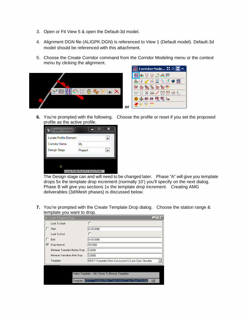
Point Controls After the templates are dropped, Point Controls need to be added that tie the template points to actual Horizontal/Vertical features or locations. Some examples:
• The template you chose may show 2 - 12’ lanes but your need a 5-lane section. • The template you chose is a 4-lane divided template with a CL to CL distance of
88’ but you have a variable CL to CL distance through part(s) of your project.
Standard Template Point Names
Adding a Point Control
1) Choose “Create Point Control” from one of the options below.

2. Enter a Control description and choose the Point you’re wanting to tie down. Then, Follow the prompts. The example below is tying the CL-L point off a 4-lane divided template to the Horizontal alignment in the DGN file that represents the CL of the Left Lanes.
Example Point Controls (Prior to Super being added.)

1) 4-Lane Divided Template.
2) 5-Lane Template.
Notice the offsets of -30 for the Point EP-L. This is moving the template point from a -12’ offset to -30’ from the CL Alignment (ML).
Parametric Constraints Parametric Constraints are the same thing as the old Define Variables in GeoPak’s process cross-section tool. They allow you to define a value for a given template component. Some examples are Shoulder Width, Pavement Thickness, Structure Thickness, Foreslope, Clear Zone, etc.

Adding a Parametric Constraint 1) Choose the command.
2) Follow the prompts.
Alignments used to change the direction of x-section processing. See the yellow x-section line below. Note: Generally EP but basically the 1st plan view element intersected and not parallel to the ML.
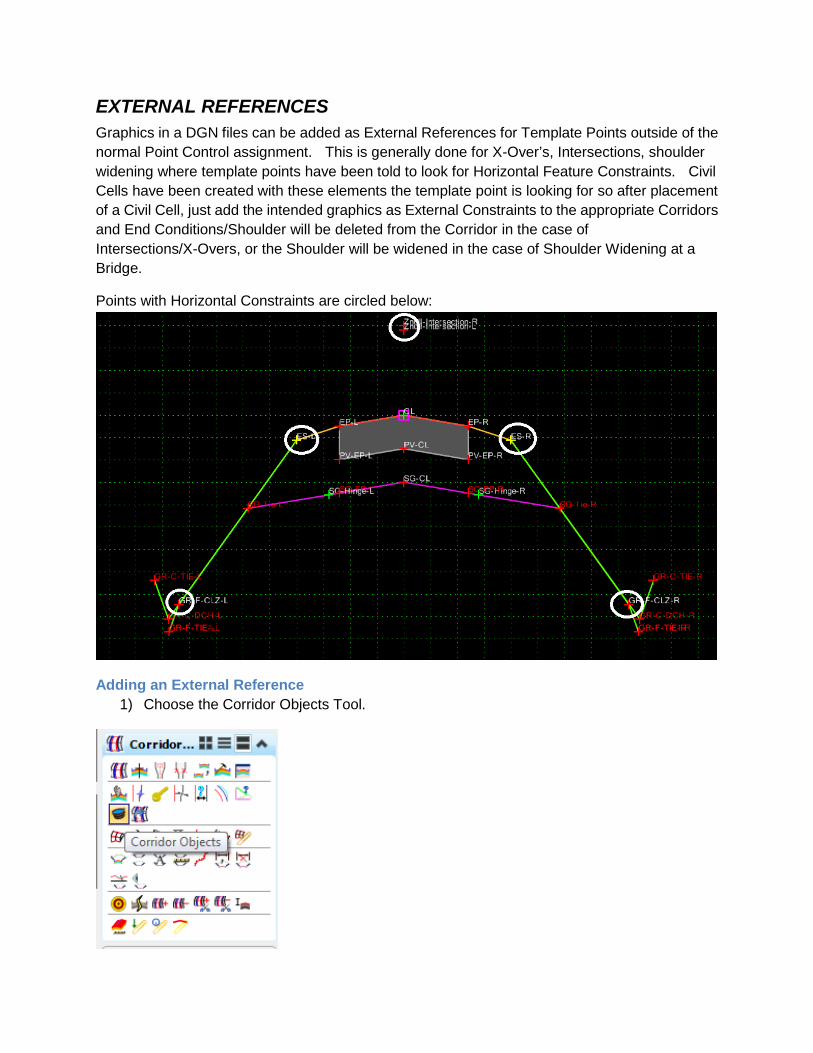
EXTERNAL REFERENCES Graphics in a DGN files can be added as External References for Template Points outside of the normal Point Control assignment. This is generally done for X-Over’s, Intersections, shoulder widening where template points have been told to look for Horizontal Feature Constraints. Civil Cells have been created with these elements the template point is looking for so after placement of a Civil Cell, just add the intended graphics as External Constraints to the appropriate Corridors and End Conditions/Shoulder will be deleted from the Corridor in the case of Intersections/X-Overs, or the Shoulder will be widened in the case of Shoulder Widening at a Bridge.
Points with Horizontal Constraints are circled below:
Adding an External Reference 1) Choose the Corridor Objects Tool.

2) Tag Add New at the top of this dialog after the External References tab is chosen.
3) You’re prompted to choose the External references which in the case above was features P-EP-INT & P-EP-INT1 which were placed with the Intersection cells. End Conditions & Shoulders of the ML Corridor are turned off as a result.
SUPERELEVATION
Superelevation should be applied next. See the Superelevation Help file for instructions. Once applied, Point Controls will be added to the Corridor.

EDIT TEMPLATE DROP You can edit a Template Drop and not affect the Library by choosing edit template drop.
SYNCHRONIZE If you make changes to a template and want it to be reflected in the template drop, choose “Synchronize with Library”.

PROCESS CORRIDOR
TARGET ALIASING & CLIPPING
A combination of Target Aliasing and Clipping can be used to tie two different Corridors together. This process is shown below between a Ramp and Mainline roadway.
1) Add the Ramp Taper, ML Corridor & Ex. Terrain as Target Alias to the Ramp Corridor.
Note that order of the Aliases does apply. This should give you the following x-section look.

2) Add a clipping reference of the Ramp Corridor to the ML Corridor & Ramp Taper Corridor.
Results are shown below.

AMG DELIVERBLES See AMG Chapter.
SURFACE TO SURFACE VOLUMES See X-Section Chapter.