
Corrective Abrasive Finishing Processes for Freeform...
14
Corrective Abrasive Finishing Processes for Freeform Surface Xun Chen 1, a 1 School of Computing and Engineering, University of Huddersfield, Huddersfield HD1 3DH, UK a [email protected] Keywords: Corrective finishing, Abrasive processing, Freeform surface, Polishing. Abstract. Traditionally, abrasive finishing process focus on producing excellent surface finish on regular form shapes. Ever increasing demands in freeform features in aerospace, energy and medicine industry requires abrasive finishing technology not only provides excellent surface finish but also is capable to correct the errors on freeform surfaces. The paper presents current development of corrective finishing technology for freeform surface. Introduction A decade ago, R. Komanduri [1] and his colleague published a paper in summarise the technical development in fine abrasive processing. By convention, polishing was meant to imply best finish without regard for shape or form accuracy, e.g., in the preparation of metallurgical samples where the objective is to remove the scratches so that microstructure can be observed after etching. It is also used for removing the damage, such as microcracks, voids, etc., caused by the previous manufacturing operation, such as grinding. Conventional lapping in contrast is used not for finish but for form accuracy, such as flatness in the case of flat objects or sphericity in the case of balls. The term honing is used, similar to lapping, for form and shape accuracy and for generating the topography to 'trap' the lubricant. Finishing is a general term used to describe any or all of these processes. Traditionally, for a precision component, grinding will provide good size and form accuracy and polishing will improve the surface finish to the highest standard. However due to the tools used in polish have relatively low stiffness and a long polish process may loss the form and size accuracy. Therefore a manual corrective polishing is sometimes required. As the advances of abrasive technology, the form accuracy becomes increasingly important to the ever demanding market. Technique advances in CNC machine tools enable a polishing process to become a good choice for form error correction, particularly for the components with tight tolerance of from accuracy and surface roughness. This means a surface with excellent form accuracy and surface finish can be achieved simultaneously on just one finishing machine. This paper presents recent development in abrasive finishing technology with particularly focus on the corrective polishing for freeform surfaces. Concept of Corrective Polishing for Freeform Surface Components with a freeform shape can be found in a wide range of applications in aerospace, medicine and energy industry, exampled by prothetic joints and turbine blades. Currently, a freeform component can be manufactured through machining directly or a mould insert used in a replication process such as injection moulding or pressing respectively. The machining process is considered as a critical element in a freeform generation. A simple example of direct machining for a freeform surface [2] is robotic grinding and polishing for turbine vane airfoil. It requires in situ measurement, profile mapping and tool path planning. More commonly, machining processes for freeform surface include the diamond turning with Fast Tool Servo (FTS) systems, the raster milling or grinding with a series of subsequent polishing steps. Usually free form surface is machined with a ball end milling cutter or grinding wheel in a machining centre. Conventional polishing is to produce a smooth, deformation-free, and scratch-free surface, which is bright, shiny, and mirror-like in appearance. Polishing minimizes all fine surface irregularities left over during the milling or grinding operation. As the tolerance getting tighter, sometimes a manual polishing can be the only choice. To avoid such
Transcript of Corrective Abrasive Finishing Processes for Freeform...

Corrective Abrasive Finishing Processes for Freeform Surface
Xun Chen1, a 1 School of Computing and Engineering, University of Huddersfield, Huddersfield HD1 3DH, UK
Keywords: Corrective finishing, Abrasive processing, Freeform surface, Polishing.
Abstract. Traditionally, abrasive finishing process focus on producing excellent surface finish on
regular form shapes. Ever increasing demands in freeform features in aerospace, energy and medicine
industry requires abrasive finishing technology not only provides excellent surface finish but also is
capable to correct the errors on freeform surfaces. The paper presents current development of
corrective finishing technology for freeform surface.
Introduction
A decade ago, R. Komanduri [1] and his colleague published a paper in summarise the technical
development in fine abrasive processing. By convention, polishing was meant to imply best finish
without regard for shape or form accuracy, e.g., in the preparation of metallurgical samples where the
objective is to remove the scratches so that microstructure can be observed after etching. It is also
used for removing the damage, such as microcracks, voids, etc., caused by the previous
manufacturing operation, such as grinding. Conventional lapping in contrast is used not for finish but
for form accuracy, such as flatness in the case of flat objects or sphericity in the case of balls. The
term honing is used, similar to lapping, for form and shape accuracy and for generating the
topography to 'trap' the lubricant. Finishing is a general term used to describe any or all of these
processes. Traditionally, for a precision component, grinding will provide good size and form
accuracy and polishing will improve the surface finish to the highest standard. However due to the
tools used in polish have relatively low stiffness and a long polish process may loss the form and size
accuracy. Therefore a manual corrective polishing is sometimes required.
As the advances of abrasive technology, the form accuracy becomes increasingly important to the
ever demanding market. Technique advances in CNC machine tools enable a polishing process to
become a good choice for form error correction, particularly for the components with tight tolerance
of from accuracy and surface roughness. This means a surface with excellent form accuracy and
surface finish can be achieved simultaneously on just one finishing machine. This paper presents
recent development in abrasive finishing technology with particularly focus on the corrective
polishing for freeform surfaces.
Concept of Corrective Polishing for Freeform Surface
Components with a freeform shape can be found in a wide range of applications in aerospace,
medicine and energy industry, exampled by prothetic joints and turbine blades. Currently, a freeform
component can be manufactured through machining directly or a mould insert used in a replication
process such as injection moulding or pressing respectively. The machining process is considered as a
critical element in a freeform generation. A simple example of direct machining for a freeform
surface [2] is robotic grinding and polishing for turbine vane airfoil. It requires in situ measurement,
profile mapping and tool path planning. More commonly, machining processes for freeform surface
include the diamond turning with Fast Tool Servo (FTS) systems, the raster milling or grinding with a
series of subsequent polishing steps. Usually free form surface is machined with a ball end milling
cutter or grinding wheel in a machining centre. Conventional polishing is to produce a smooth,
deformation-free, and scratch-free surface, which is bright, shiny, and mirror-like in appearance.
Polishing minimizes all fine surface irregularities left over during the milling or grinding operation.
As the tolerance getting tighter, sometimes a manual polishing can be the only choice. To avoid such

time and cost intensive process, many efforts were made in developing new polishing technology –
namely corrective polishing. Due to high demands on the geometrical precision in corrective
polishing, the form accuracy is usually achieved by iterative correction loops consisting of a
machining step, a surface measurement and the generation of an adapted NC machining programme
in order to compensate for the form deviation identified. As a consequence, a series of new challenges
has to be addressed.
Besides the requirements on the form accuracy and surface roughness, the integrity of surface
regarding the material property is of equally importance. In view of the peculiarities of the work
materials (advanced ceramics, optical glasses, semiconductor materials, aerospace alloys etc.), the
stringent requirements of these materials in practice, the need to remove very small amounts of
material (atomic bits) to minimize or eliminate brittle fracture, the very high surface finish and form
accuracy requirements, and the required surface integrity (i.e., minimal or no surface or near surface
damage including metallurgical changes, residual stresses, defects such as micro-cracks and material
re-deposits), it is necessary to consider the corrective abrasive finishing process as a system.
Komanduri et al [1] listed 9 points of consideration for ultraprecision machining system, most of
which are applicable to corrective abrasive finishing process. Here the key elements are iterated.
1. High precision, vibration-free, rigid machine tool;
2. High resolution motion control;
3. Thermal stability;
4. Feedback control;
5. High loop stiffness between the tool and the workpiece;
6. Submicron abrasives of uniform grain size bonded into a wheel or in the form of a coated
abrasive or as free abrasive;
7. Suitable dressing techniques for different bonded abrasive tools;
8. Ultraprecision metrology system integrated into the machine tool but isolated from the
response of the machine tool during machining;
9. High level of clean environment including temperature, vibration, humidity, and dust control.
The first 4 points are related to machine tools performance and the following three points are
associated to tool preparation, albeit the point 5 is debatable for polishing, where soft polishing pads
are often used.
Machine Tool Dynamics
To achieve a freeform surface error correction, the minimum control axes should be 5 axes assuming
the datum of component can be aligned on the machine precisely. Due to the locating error is
unavoidable, more degrees of freedom have to be controlled by introducing more control axes.
Another challenge of freeform polishing is the changing mismatch between machining surface of the
polishing tool and required surface of the workpiece. For easy process control, control systems with 6
or more controllable axes are commonly used to provide extra movement for the mismatch
correction. Brecher et al [3] developed a double-V-parallel kinematic module with four degrees of
freedom for their freeform machining research. As shown in Fig. 1 the module can run in force
control mode and is capable of superimposing eccentric movements to the rotating polishing tools so
as to control tool orientation correctly to the local surface normal. The unit is designed as a closed
system that can be mounted on various machine tools. The base machine guides the adaptive
polishing unit over the workpiece surface using three axes only; the polishing module itself provides
the local movements including the angular alignment for ensuring constant process parameters.
As a part of research on the Euro50 telescope development, a Zeeko polishing machine centres
was designed and manufactured for aspheric lens polishing [4,5]. The CNC control system provides
synchronized control and power amplifiers for the X, Y, Z, A, B axes and the turntable rotation (C). It
also provides control of the tool rotation (H axis) speed. A schematic machine structure is illustrated
in figure 2. The machine is particularly suitable rotational aspheric surface polishing. It is also
capable to polishing any type of freeform as long as the curvature radius of concave surface is larger
than that of polishing tool. At Huddersfield, an excellent surface finish of Sa 2.8 nm was achieved in

a knee condyle section polishing automatically on a Zeeko IPR 200 machine [6]. Fig 3 is the
photograph of the polished knee joint component. A unique feature of the Zeeko polishing machine is
that the polish bonnet is supported by a pressurized air; so that the stiffness of the polish pad becomes
controllable through air pressure.
Figure 1. Four-degree-freedom double-V-parallel polishing unit [3]
Figure 2. Zeeko machine structure [4, 5] Figure 3. A polished knee joint component [6]
Robotic grinding and polishing is a common chamfering, deburring and finishing method for
complex components [7-11]. Since a robot is capable to facilitate over 6 degrees of freedom, it is also
used for freeform correction. Huang et al [2] reported their researches on turbine-vane overhaul
application. The system applies a sand belt wheel as grinding and polishing media. Therefore the
setup is a linear contact mechanism, which means their system is actually a 2D error compensation
system. Through the path planning enabled a 3D freeform surface to be machined, many restrictions
would remain. Because the abrasive grits are bonded on the sand belt, the effects of tool wear on
material removal rate should be compensated. The suggested compensation methods are increasing
belt speed and decreasing federate, which were found satisfactory with a certain limit within the tool
life. A force feedback system was employed for the surface profile control through tool path design.
Models for Error Correction Finishing
A successful corrective polishing system should be capable to remove materials precisely according
to the errors at the different positions of the component. Knowledge of material removal in finishing
process is essential for error correction. Early developed models for the analysis of material removal
in finishing process are Preston equation and Archard equation. According to Preston equation [12]

rp pvCdt
dz= (1)
The equation presents the material removal rate dz/dt is determined by the relative velocity vr, the
polishing pressure p. The constant Cp represents the effects of other influential process parameters
that are not taken into account. So, the Preston coefficient has to be determined experimentally for
each single polishing system consisting of polishing tool, workpiece and polishing slurry. From
tribological point of view, Archard equation predicts the abraded wear volume Vw [13].
H
sFKV n
w = (2)
Where Fn is the normal load, s is the sliding distance and H is the abraded workpiece surface. From
Preston and Archard models, it can be seen that the material removal can be related to the normal load
or pressure acting on the workpiece surface.
A true 3D polishing method being capable to correct errors was studied by Wu, Kita and Ikoku
[14]. In this method, the polishing tool is an elastic spherical grinding wheel. Considering the micro
feature correction, the real depth of cut is of significance in corrective polishing. Wu et al illustrated a
good linear relationship (as shown in Fig. 4) between actual depth of cut δ and polishing parameter Sp,
which defined as
v
pHf
pfVS
)( += (3)
Where V is polishing speed, f is feed speed, p is contacting pressure and Hv is workpiece hardness.
This relationship indicates that the polishing materials removal can be controlled by contact pressure,
polishing speed and feed speed. They also indicated that the pressure distribution between the tool
and workpiece should be considered for form correction. For a true 3D surface error correction,
pressure distribution control will be an important issue. Wu et al [14] also noticed the effects of tool
orientation on the materials removal. This provides an extra route for form error correction.
Figure 4. Polishing materials removal [14]
The pressure distribution plays an important role in the corrective finishing process. Roswell et al
[15] investigated into contact stress in a polishing process. They classified the contact stress
distribution into non-Hertzian circular contact and Hertzian elliptic contact, from which the
relationship between polishing forces and polish pressure can be established. Based on the Hertzian
contact theory, the pressure distribution will follow an elliptic distribution, where the maximum
contact pressure is at the centre of the contact. The mean pressure is two thirds of the maximum
pressure. The contact force F can be calculated as:
k
PkEF
3
)'(2 3220∆
=π
(4)

Where k is semi-minor to semi-major axis of contact ellipse, ∆ is contact parameters determined
by contact geometrical features and material properties, θθπ
dkkE ∫ −=2/
0
22 sin'1)'( and
21' kk −= . By considering the kinetic friction coefficient µk, the friction torque of contact Tf is:
( ) 3/1
3/4
)'(2
3)/11(
9
2∆
+= kE
kFkT kf
ππµ (5)
As demonstrated in Eqs. 4 and 5, the contact stress distribution depends on the contact geometry.
The constant force did not generate constant removal rate when the surface curvature changed.
For machining of precision freeform components, different data formats may be used in design,
machining and metrology on their own merits. Transforming data formats from a conventional matrix
based definition of single surface points into a closed polynomial description (e.g. splines) or from
one polynomial description into another is accompanied with losses in precision and time intensive
calculations. The machining of ultra-precision freeform components with form tolerances in the
sub-micron range requires a close interaction between the machine tool, the process and the
procedure for the NC tool path generation. Especially for the optical freeform machining the choice
of a data-format for the surface description as well as the calculation of the tool path is crucial for the
overall achievable quality of the workpiece. Thus, the consistency of the data format in describing a
freeform surface geometry is essential and critical in handling metrology data, in planning the best
suited tool path trajectory as well as in actively controlling the machine tool during operation. This is
highly important issue for ensuring the required form accuracy as well as in enabling a highly
effective and deterministic machining.
A data format based on NURBS (Non-Uniform-Rotational-B-Spline) was introduced [16, 17] in
order to use it for the highly precise description of freeforms during the design, for the calculation of
complex tool trajectories, for the calculation of corrective re-machining steps and for the handling in
a machine control system. Some reasons for using NURBS are that they:
• offer one common mathematical form for both, standard analytical shapes (e.g. conics) and
free form shapes;
• provide the flexibility to design a large variety of shapes;
• can be evaluated reasonably fast by numerically stable and accurate algorithms;
• are invariant under affine as well as perspective transformations;
• are generalizations of non-rational B-splines and non-rational and rational Bezier curves and
surfaces.
A NURBS based surface is defined as follows:
∑∑= =
=n
i
m
j
jiji vuRvu0 0
,, ),(),( PS (6)
The rational basis functions
∑∑= =
=n
k
m
l
lkqlpk
jiqipi
ji
wvNuN
wvNuNvuR
0 0
,,,
,,,
,
)()(
)()(),( (7)
are weighted p-th and q-th degree B-Spline basis functions Ni,p with the parameters u and v. The
basis functions are activated by the knot vectors
{
=+
+
+ 1
1
1
1,...,1,,...,,0,...,0p
np
p
uu321
U (8)
and equivalently V according to u and v. There is a fixed number of active basis functions in one
knot span. Hence surface modifications have only local affects. The surface lies in the convex hull of
the control net consisting of the control points P = {Pi,j}. Each control point has a weight w = {wi,j}
representing a proportional attraction or rejection of the surface from this point.

Brecher et al [3] investigated the method for a tool path calculation based on the NURBS data
format. By using the data format NURBS, the data in the data chain can be easily exchange.
Furthermore, NURBS allow local tool path manipulations for the correction of local form deviations.
The key issue in their methods is to minimise the distance vector between desired surface and
machined surface within a limited time span. An online data processing during the trajectory
calculation can reduce pre-processing time, because no data transformation is required during the
process chain from start to finish with the measurement. However, due to the required high number of
real time data calculations, an online machine control with NURBS is still not possible for multi axis
control with a 650 MHz CPU (Central Processing Unit) system. Therefore the trajectories are stored
in G-Code format for the machine and in a series of splines for the adaptive polishing module. A
multi-axis movement control was realised by combining the usages of NURBS and conventional
G-code. The corrective polishing process is controlled by feed rate and dwelling time calculated from
error maps.
With the surface model available for error analysis, the capability of error measurement becomes
next line of consideration for the freeform error corrective finishing.
Metrology requirement
The errors to be corrected in a corrective polishing are normally at the level of submicron to micron
range. The prosthetic components are good examples of precision freeform surface with tight
tolerances. As an example, dimensional tolerance of medical implant components can be less than 0.2
µm and surface finish requirement can be 0.05 µm for hip joints [18, 19]. For such high standard
requirement, the measurement is usually carried out in situ. If the measurement has to be carried out
off-line, the machine has to have a facility to enable the component to be relocated at the same
position.
The requirements for medical implants can be found in the BS and ISO specifications: BS
7251-14:1998, ISO 7207-2:1998 [18, 19]. It can be noted that there are no current guidelines for the
tolerances of freeform shape. The dimensional tolerances for freeform component are not stipulated
in the standards. Therefore where this is the case the tolerances guidelines for hips are used or the
tolerances are driven by company standards. In practice the surface metrology requirements are
routinely bettered in normal manufacture i.e. the current achievable surface finish is within 5-10 nm
compared to the stated 50 nm in the standards. This is due to the fact that standards are not reviewed
as often as companies advance there manufacturing practises.
As the polished surface finish fall into nanometre range, local surface features have significant
influence to the component performance. Traditional 2D surface measurement cannot provide
sufficient information to the component manufacturers and end-users. Three-dimensional surface
measurement becomes increasingly important, particularly for orthopaedic component
manufacturing. Blunt and Jiang [20] compared numerous surface topographical measurement
techniques and conclude:
1. In the 2D mode stylus instruments can be employed for monitoring and controlling the
manufacturing process of the femoral heads though good environmental control and
instrument maintenance is required. These instruments can be used for 3D measurement of
the surface of the heads and acetabular cups only when the table errors can be corrected for
by new digital techniques or improved translation devices.
2. The focus detection instruments can be used in manufacturing process of the femoral heads
and acetabular cups when the slopes of scattering region on the bearing surface are less than
standard critical angle limited by the objective numerical aperture.
3. The phase-shifting interferometers can offer the best method for 3D measurement of femoral
heads due to large measurement range and nano-meter resolution.
4. AFM is ideal for description of the detail of surface structure of the femoral heads though for
full characterization many measurements need to be carried out.
They recommend that contacting and non-contacting measurement should be implemented
according to different analyzing requirements of the orthopaedic joint prostheses. Another important

development in surface metrology is surface characterization identification and evaluation. Jiang and
Blunt [21] provide a wavelet method for the feature extraction from 3D surface measurement. These
technique developments are important support to the quality improvement of corrective finishing
processes.
Controllable Finishing Process and Its Control
Similar to conventional finishing process, a corrective finishing process can be influenced by a series
of controllable or uncontrollable parameters. The type of abrasive, polishing cloth or pads, polishing
fluid, the pressure acting between the workpiece and tools and kinematical movement are all
important for the process quality and efficiency. In research of material removal mechanism, Evans et
al [22] defined four components involved in a finishing process. They are the workpiece, abrasive
granule, fluid and lap. The mechanism of interactions between these components is still not clear.
Understanding these interactions seems critical in dealing with the changes in process input variables
to productivity and part quality. This is particularly true for the development of corrective abrasive
finishing technology.
Workpiece. The object of finishing is to modify the workpiece in size, shape and surface texture.
Nowadays, the materials subject to finishing process are of wide spectrums, from brittle materials to
ductile materials, from homogeneous single materials to composite multiphase materials. The
material physical property and machinability are important influential factors to the finished surface
integrity.
Abrasive Granule. The function of abrasive granules in the slurry is to mechanically remove
materials from the surface of the workpiece. The granules themselves can be distinguished by a
number of factors, including chemical composition, size, size distribution, shape and concentration,
while the effect of each of these factors may be important or insignificant. Commonly used polishing
abrasives are diamond, aluminium oxide and silicon carbide. Diamond abrasives usually produce less
surface relief than other abrasives. The abrasives used for grinding are normally down to the size
around 5 µm. Polishing abrasives are usually smaller than that used in grinding. For precision
polishing, abrasive grit size can be submicron. Under some conditions, agglomeration of smaller
particles becomes important, affecting the average size and the size distribution. In some cases, the
granules fracture, changing the average particle size and shape during the polishing process. These
changes will certainly influence the stability and predictability of the finishing processes, since the
granule size and its distribution have great effects on material removal rate [22-26].
Fluid. The abrasives used in polishing are usually in forms of paste or abrasive powders in
colloidal suspension or polishing oil, water or organic solvent (ethylene glycol, alcohol, kerosene,
glycerol). The fluid phase of the slurry may be characterized by its chemical composition and by its
physical properties. Chemical compositions of fluids include water and nonaqueous fluids like
hydrocarbons and alcohols. The pH of the fluid may be controlled by addition of acids or bases, or by
the use of a buffer system. The fluid in finishing may promote material removal by chemical
reactions. Physical properties of the fluids affect both fluid dynamics and material transport in
polishing. These properties include viscosity, density and thermal conductivity, all of which are
pressure and temperature dependent. These properties can also be varied by changes in the chemical
composition of the fluid.
Lap. In the context of material removal mechanisms, the lap imposes relative motion between the
granules and the workpiece and affects slurry and swarf transport through the contact. The lap can be
a plate, pad, cloth or thin film with different stiffness. The materials of lap can be metal, composite or
organic materials. Stiffness, porosity, wear rate, thermal and elastic properties of the lap are of
functional importance. As a general rule, a good polishing lap should: (a) hold the abrasive media; (b)
have a long life; (c) not contain any foreign material, which may cause scratches; (d) have appropriate
hardness/softness; and (e) be clean of any processing chemicals, which may react with workpiece.
Material removal in a finishing process is the result of interaction of these four components. Evans
et al [22] summarized four hypotheses of material removal mechanism, namely, brittle crack, plastic
flow, chemical dissolution and friction wear. The first two hypotheses are commonly recognized in

grinding, which are evidenced by removed chips. The friction wear hypothesis was developed in
response to the lack of information provided by the chemical hypothesis regarding the influence
exerted by the polishing medium. Actual polishing will proceed through a combination of material
removal mechanisms, depending on the conditions in the system. To date, no one has succeeded in
developing a quantifiable material removal model. Many works remains to be done. In order to guide
corrective finishing control, many researchers [14, 27-29] are experimentally investigating the
relationship between material removal rate and influential process parameters. The commonly
considered parameters include polishing speed, feed rate, pressure between tool and workpiece, and
tool type, shape and orientation.
In theory the error correction will be a straightforward job if a finishing process is deterministic. In
practice, successful error correction relies on carefully planned strategy and tool path design. While
investigating the hydrodynamic polishing process, Su et al [29] explained a machining principle – if
the curvature effect of error profile is negligible, to obtain an arbitrary shape, the machining time
distribution at the machining area should be a linear function of the desired profile. As a consequence,
two machining strategies were described as machining corollaries.
(1) If the curvature effect of a desired profile is negligible and the machining zone area is infinitely
small, to obtain this profile, the time distribution of tool motion should be a linear function of the
profile. This corollary means to machine an arbitrary shape is simply to control the tool motion to
have a time distribution similar to the desired profile.
(2) To obtain an arbitrary profile, the layer-by-layer removing strategy can be used. In each layer,
the removed thickness is uniform. To do so, the tool is controlled to have a uniform machining time
distribution at each grid of machining area of the layer, where the grid size is much smaller than the
dimension of machining zone. Particularly, the boundary of each layer with a specific depth should be
equal to the contour of the desired profile at the corresponding depth.
To satisfy the premise of the machining principle – the curvature effect of error profile is
negligible, the machining spot should be very small. For most polish process, this premise is not easy
to match. For time-dwell strategy, there may be two difficulties: over cutting on the boundary of
machining area and overlap in tool path design. The over cutting may be moderated by reducing the
diameter of tool, increasing the elastic modulus of tool, or reducing the applied load. Another possible
way to reduce the depth of over-cut is to rearrange properly the machining time near the boundary.
Regarding the tool path overlap design, it is important to make sure the ripples created by tool path
are within the tolerance limit.
Commonly used of corrective strategies are dwelling time depending on the position of the
workpiece [22, 30, 31]. This is because the material removal rate is relatively constant with increasing
polishing time [27]. The longer the tool dwells, the more materials are removed. A dwell time map
will established to match the error measured and then translated into federate for the process control.
With such strategy, Walker et al [30] demonstrated a successful arbitrary form peak-to-valley error
correction from 20.4 to 6.2 microns. The limitations polishing a free-form part are currently due to the
quality of the metrology as delivered by a CMM. By applying a limited load (2 N) on polishing tool,
Su et al [29] demonstrated that the hydrodynamic polishing can create both uniform depth and
parabolic shape pockets with root mean square waviness less than 30 nm by layer-by-layer strategy.
The layer-by-layer strategy still has over-cut and under-cut problem when the surface profile falls
between the layers. Su et al [31] developed a modified layer-by-layer method to cope such problem.
In order to correct spot error on freeform surface, Walker et al [28] developed a corrective
polishing method named as “precessions” process. The polishing tool used comprises an inflated,
bulged rubber membrane of spherical form, covered with nonpitch flexible polishing surfaces. The
membrane moulds itself around the local asphere, retaining good contact everywhere. Such a
membrane has the property that the polishing tool stiffness and the contact area can be controlled
independently by air pressure and axis offset when it is used on a Zeeko machine. When the polishing
tool feeds toward the workpiece surface perpendicularly (pole-down spinning), the tool exhibits zero
surface-speed at centre, rising linearly to a maximum at the periphery. According to Preston equation
and Hertizian contact pressure distribution, the material removal in the contact spot presents a
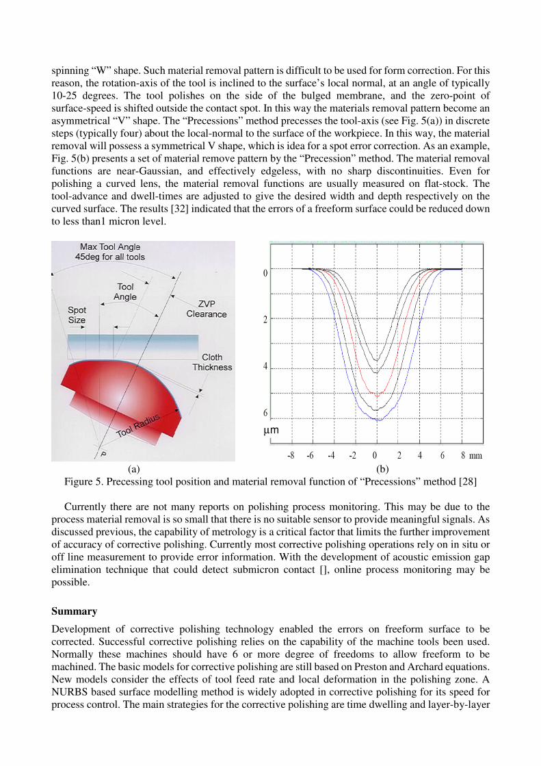
spinning “W” shape. Such material removal pattern is difficult to be used for form correction. For this
reason, the rotation-axis of the tool is inclined to the surface’s local normal, at an angle of typically
10-25 degrees. The tool polishes on the side of the bulged membrane, and the zero-point of
surface-speed is shifted outside the contact spot. In this way the materials removal pattern become an
asymmetrical “V” shape. The “Precessions” method precesses the tool-axis (see Fig. 5(a)) in discrete
steps (typically four) about the local-normal to the surface of the workpiece. In this way, the material
removal will possess a symmetrical V shape, which is idea for a spot error correction. As an example,
Fig. 5(b) presents a set of material remove pattern by the “Precession” method. The material removal
functions are near-Gaussian, and effectively edgeless, with no sharp discontinuities. Even for
polishing a curved lens, the material removal functions are usually measured on flat-stock. The
tool-advance and dwell-times are adjusted to give the desired width and depth respectively on the
curved surface. The results [32] indicated that the errors of a freeform surface could be reduced down
to less than1 micron level.
µmµm
(a) (b)
Figure 5. Precessing tool position and material removal function of “Precessions” method [28]
Currently there are not many reports on polishing process monitoring. This may be due to the
process material removal is so small that there is no suitable sensor to provide meaningful signals. As
discussed previous, the capability of metrology is a critical factor that limits the further improvement
of accuracy of corrective polishing. Currently most corrective polishing operations rely on in situ or
off line measurement to provide error information. With the development of acoustic emission gap
elimination technique that could detect submicron contact [], online process monitoring may be
possible.
Summary
Development of corrective polishing technology enabled the errors on freeform surface to be
corrected. Successful corrective polishing relies on the capability of the machine tools been used.
Normally these machines should have 6 or more degree of freedoms to allow freeform to be
machined. The basic models for corrective polishing are still based on Preston and Archard equations.
New models consider the effects of tool feed rate and local deformation in the polishing zone. A
NURBS based surface modelling method is widely adopted in corrective polishing for its speed for
process control. The main strategies for the corrective polishing are time dwelling and layer-by-layer

methods. Further improvement of corrective polishing technology depends on the application of
better metrological facilities and online process monitoring.
References
[1] R. Komanduri, D.A. Lucca, and Y. Tani, Technological Advances in Fine Abrasive Processes,
Annals of the CIRP, Vol.46, No. 2, (1997), pp. 545-596.
[2] Robotice grinding and Polishing for turbine-vane overhaul, J. of materials Processing
Technology, Vol. 127(2002) pp.140-145
[3] C. Brecher, S. Lange, M. Merz, F. Niehaus, C. Wenzel, M. Winterschladen, NURBS Based
Ultra-Precision Free-Form Machining, Annals of the CIRP, Vol.55, No. 1, (2006), pp. 547-550.
[4] D. D. Walker, , R. Freeman, G. McCavana, R. Morton, D. Riley, J. Simms, D. Brooks, E. D.
Kim, A. King, The Zeeko/UCL Process for Polishing Large Lenses and Prisms, Proc. of SPIE,
Vol. SPIE-4411 (2002) pp.106-111.
The Euro50 Extremely Large Telescope”, Torben Andersen, Arne L Ardeberg, Jacques Beckers,
Proceedings SPIE Apr 2002 Vol. 4840 pp 214-225.
[5] R. G. Bingham, D. D. Walker, D-H. Kim, D. Brooks, R. Freeman, D. Riley, A novel automated
process for aspheric surfaces, Proc. of SPIE, Vol. SPIE-4093 (2000) pp.445-450.
[6] P. Charlton, L. Blunt, Surface and form metrology of polished “freeform” biological surfaces,
Wear, Vol. 264 (2008) pp.394–399.
[7] T. M. Stephen, L. M. Sweet, M. C. Good, M. Tomizuka, Control of tool/workpiece contact force
with application to Robotic deburring, IEEE J. Robotic. Autom. RA-3(1) (1987) pp. 7-18.
[8] G. M. Bone, M. A. Elbestawi, R. Lingarkar, L. Liu, Force control for robotic deburring, ASME J.
Dyn. Syst. Meas. Cont. Vol.113 (1991) pp.395-400.
[9] R. Hollowell, R. Guile, An analysis of robotic chamfering and deburring, ASME DSC-6 (1987)
pp.73-79.
[10] D. F. Ge, Y. Takeuchi, N. Asakawa, Dexterous polishing of overhanging sculptured surface with
6-axis control robot, Proceedings of the IEEE International Conference on Robotics Automation,
(1995) pp.2090-2095.
[11] F. Ozaki, M. Jinno, T. Yoshimi, K. Tatsuno, M. Takahashi, M. Kanda, Y. Yamada, S. Nagataki,
A force controlled finishing robot system with a task-directed robot Language, J.
Robotic.Mechatronics, Vol.7, No. 5 (1995) pp.383-388.
[12] F. W Preston, The theory and design of plate glass polishing machines. J Soc Glass Technol
Vol.11 (1927) pp. 214–256.
[13] J. F. Archard, Contact and rubbing of flat surfaces. J Appl Phys. Vol.24, (1953) pp. 981–988.
[14] X. Wu, Y. Kita, K. Ikoku, New polishing technology of free form surface by GC, Journal of
Materials Processing Technology, Vol. 187–188 (2007) pp. 81–84.
[15] A. Roswell, F. Xi, G. Liu, Modelling and analysis of contact stress for automated polishing, Int.
J. of Mach. Tools & Manuf. Vol.46, (2006), pp.424-435.
[16] David F. Rogers, Rae A. Earnshaw (editors), "State of the Art in Computer Graphics -
Visualization and Modeling", 1991, New York, Springer-Verlag, pp. 225 - 269
[17] Les Piegl, "On NURBS: A Survey", Jan 01, 1991, IEEE Computer Graphics and Applications,
Vol. 11, No. 1, pp. 55 – 71.

[18] BSI 7251-4: 1997; Orthopaedic joint prosthesis – Part 4: Specification for articulating surfaces
made of metallic, ceramic and plastic materials of hip joint prosthesis.
http://www.bsi-global.com/index.xalter
[19] BS 7251-14:1998, ISO 7207-2:1998 Orthopaedic joint prostheses. Components for partial and
total knee-joint prostheses. http://www.bsi-global.com/index.xalter
[20] L. Blunt, X. Q. Jiang . Three dimensional measurement of the surface topography of ceramic and
metallic orthopaedic joint prostheses. Journal of Materials Science: Materials in Medicine,
Volume 11, Number 4 (April 2000), pp. 235-246.
[21] X. Q. Jiang, L. Blunt, Third generation wavelet for the extraction of morphological features from
micro and nano scalar surfaces, Wear, Vol. 257 (2004) pp.1235–1240.
[22] C.J. Evans, E. Paul, D. Dornfeld, D.A. Lucca, G. Byrne, M. Tricard, F. Klocke, O. Dambon, B.A.
Mullany, Material Removal Mechanisms in Lapping and Polishing, Vol. 52, No. 2, (2003) pp.
611-633.
[23] D.D. Walker, A.T.H. Beaucamp, D. Brooks , R. Freeman, A. King, G. McCavana, R. Morton, D.
Riley, J. Simms, Novel CNC polishing process for control of form and texture on aspheric
surfaces, Proceedings of SPIE – The Int. Soc. for Opt. Eng., Vol. 4767 (2002) pp.99-105.
[24] Material Removal Mechanisms in Lapping and Polishing, CIRP Annals - Manufacturing
Technology, Vol. 47, No. 1, (1998) pp. 239-244.
[25] R. S. Dwyer-Joyce, R. S. Sayles and E. loannides, An investigation into the mechanisms of
closed three-body abrasive wear, Wear, Vol 175 (1994) pp. 133-142.
[26] Aghan R. L. and Samuels L. E. Mechanisms of abrasive polishing, Wear, Vol.16 (1970), pp.
293-301.
[27] E. Brinksmeier, O. Riemer, A. Gessenharter, Finishing of structured surfaces by abrasive
polishing, Precision Engineering Vol.30 (2006) pp. 325–336.
[28] D. D. Walker, D. Brooks, A. King, S. w. Kim, The ‘Precessions’ tooling for polishing and
figuring flat, spherical and aspheric surfaces, Vol.11, No. 8, (2003) pp.958-964.
[29] Y. T. Su, C. C. Horng, S. Y. Wang, S. H. Jang, Ultra-precision machining by the hydrodynamic
Polishing process, Int. J. Mach. Tools Manuf., Vol. 36, No. 2, (1996) pp. 275-291.
[30] D.D. Walker, A.T.H. Beaucamp, V. Doubrovski, C. Dunn, R. Freeman, G. Hobbs, G.
McCavana, R. Morton, D. Riley, J. Simms, X. Wei, New results extending the Precessions process to
smoothing ground aspheres and producing freeform parts, Proc. of SPIE, Vol. SPIE-5965 (2005) pp.
249-255.
[31] Y. T. Su, C. C. Horng, J. Y. Sheen, H. JAR-Sian, A Process Planning Strategy for Removing an
Arbitrary Profile by Hydrodynamic Polishing Process, Int. J. Mach. Tools Manuf., Vol. 36, No. 11,
(1996) pp. 1227-1245.
[32] D. D. Walker, A. T. H. Beaucamp, D. Brooks, V. Doubrovski, M. Cassie, C. Dunn, R. Freeman,
A. King, M. Libert, G. McCavana, R. Morton, D. Riley, J. Simms, New Results from the Precessions
Polishing Process Scaled to Larger Sizes, Proc. of SPIE, Vol. SPIE-5494 (2004) pp.71-80.

If a polishing process has a deterministic machining nature and is capable of removing an arbitrary
profile to a desired precision, it has two main advantages in performing the error correction task as
compared to the trajectory controlled machining methods. One advantage is that the precision
requirement of the servo-mechanisms for a polishing machine is much lower than the machining
precision which can be achieved through error compensation by the polishing process. This is
because the high positioning precision requirement in the z-direction for the trajectory decided
machining processes is unnecessary for a polishing process. It is replaced by the need for an accurate
machining rate control. In other words, by attaining a proper machining rate control of the polishing
process, the machining precision of work surface can be greater than the positioning precision of the
machine tool (see discussion in Appendix A). The other advantage is that the high structure rigidity
requirement (needed for the trajectory controlled machining methods) is relieved for a polishing
process. This is because the structure deflection or vibration has a negligible effect on the machining
performance of a polishing process [23]. As a result, for the error compensation purpose a
deterministic polishing process is a better choice.
AE
Machine tool kinematics
Error measurement
More research is required to guide the selection of suitable process parameters.
1. D.D. Walker, A.T. Beaucamp, R.G. Bingham, D. Brooks, R. Freeman, S.W. Kim, A.M. King,
G. McCavana, R. Morton, D. Riley, J. Simms, “Precessions process for efficient production of
aspheric optics for large telescopes and their instrumentation,” in Specialized Optical Developments
in Astronomy, eds. E. Atad-Ettedgui, S. D'Odorico, Proc. SPIE 4842, 73-84, 2002
2. D. Walker, D. Brooks, R. Freeman, A.M. King, G. McCavana, R. Morton, D. Riley, J. Simms,
“First aspheric form and texture results from a production machine embodying the Precessions
process,” in Optical manufacturing and Testing IV, Proc. SPIE, 4451, 267-276, 2000
3. ‘The ‘Precessions’ Tooling for Polishing and Figuring Flat, Spherical and Aspheric Surfaces’,
D.D. Walker, D. Brooks, A. King, R. Freeman, R. Morton, G. McCavana, S-W Kim , Optics Express,
Published by Optical Society of America on http://www.opticsexpress.org/, Vol. 11, issue 8, April
21st, pp958-964
Dipayan Jana, SAMPLE PREPARATION TECHNIQUES IN PETROGRAPHIC
EXAMINATIONS OF CONSTRUCTION MATERIALS:
A STATE-OF-THE-ART REVIEW; PROCEEDINGS OF THE TWENTY-EIGHTH
CONFERENCE ON CEMENT MICROSCOPY, DENVER, COLORADO, U.S.A., APRIL 30 –
MAY 4, 2006
Jana, D., Sample Preparation Techniques in Petrographic Examinations of Construction Materials: A
State-of-the-art Review, Proceedings of the 28th Conference on Cement microscopy, ICMA, Denver,
Colorado, 2006, pp. 23-70.
Process monitoring
It has been reported that difference lap materials would make significant difference in surface finish.
The compliance of polishing system is an important common feature for corrective polishing
processes in achieving high accuracy. It allows the surface finish to be improved without losing form

accuracy. To enable corrective polishing tool path planning is essential element for the error
correction. This depends on the method of freeform surface modelling and error measurement.
All manuscripts must be in English. Please keep a second copy of your manuscript in your office (just
in case anything gets lost in the mail). When receiving the manuscript, we assume that the
corresponding authors grant us the copyright to use the manuscript for the book or journal in question.
Should authors use tables or figures from other Publications, they must ask the corresponding
publishers to grant them the right to publish this material in their paper.
Use italic for emphasizing a word or phrase. Do not use boldface typing or capital letters except for
section headings (cf. remarks on section headings, below). Use a laser printer, not a matrix dot
printer.
Organization of the Text
Section Headings. The section headings are in boldface capital and lowercase letters. Second level
headings are typed as part of the succeeding paragraph (like the subsection heading of this
paragraph).
Page Numbers. Do not print page numbers: Please number each sheet toward the middle near the
bottom (outside the typing area) with a soft pencil.
Tables. Tables (refer with: Table 1, Table 2, ...) should be presented as part of the text, but in such
a way as to avoid confusion with the text. A descriptive title should be placed above each table. The
caption should be self-contained and placed below or beside the table. Units in tables should be given
in square brackets [meV]. If square brackets are not available, use curly {meV} or standard brackets
(meV).
Figures. Figures (refer with: Fig. 1, Fig. 2, ...) also should be presented as part of the text, leaving
enough space so that the caption will not be confused with the text. The caption should be
self-contained and placed below or beside the figure. Generally, only original drawings or
photographic reproductions are acceptable. Only very good photocopies are acceptable. Utmost care
must be taken to insert the figures in correct alignment with the text. Half-tone pictures should be in
the form of glossy prints. If possible, please include your figures as graphic images in the electronic
version. For best quality the pictures should have a resolution of 300 dpi(dots per inch
Equations. Equations (refer with: Eq. 1, Eq. 2, ...) should be indented 5 mm (0.2"). There should
be one line of space above the equation and one line of space below it before the text continues. The
equations have to be numbered sequentially, and the number put in parentheses at the right-hand edge
of the text. Equations should be punctuated as if they were an ordinary part of the text. Punctuation
appears after the equation but before the equation number, e.g.
c2 = a
2 + b
2 (1)
Literature References
References are cited in the text just by square brackets [1]. (If square brackets are not available,
slashes may be used instead, e.g. /2/.) Two or more references at a time may be put in one set of
brackets [3,4]. The references are to be numbered in the order in which they are cited in the text and
are to be listed at the end of the contribution under a heading References, see our example below.
Summary

On your floppy disk, please indicate the format and word processor used. Please also provide your
phone number, fax number and e-mail address for rapid communication with the publisher. Please
always send your disk along with a hard copy that must match the disk's content exactly If you follow
the foregoing, your paper will conform to the requirements of the publisher and facilitate a
problem-free publication process.
[1] Dj.M. Maric, P.F. Meier and S.K. Estreicher: Mater. Sci. Forum Vol. 83-87 (1992), p. 119
[2] M.A. Green: High Efficiency Silicon Solar Cells (Trans Tech Publications, Switzerland 1987).
[3] Y. Mishing, in: Diffusion Processes in Advanced Technological Materials, edtied by D Gupta
Noyes Publications/William Andrew Publising, Norwich, NY (2004), in press.
[4] G. Henkelman, G.Johannesson and H. Jónsson, in: Theoretical Methods in Condencsed Phase
Chemistry, edited by S.D. Schwartz, volume 5 of Progress in Theoretical Chemistry and Physics,
chapter, 10, Kluwer Academic Publishers (2000).
[5] R.J. Ong, J.T. Dawley and P.G. Clem: submitted to Journal of Materials Research (2003)
[6] P.G. Clem, M. Rodriguez, J.A. Voigt and C.S. Ashley, U.S. Patent 6,231,666. (2001)
[7] Information on http://www.weld.labs.gov.cn


![[Case Study] FreeFORM Technologies](https://static.fdocuments.us/doc/165x107/61a3ba6c56cde505261a6e2b/case-study-freeform-technologies.jpg)