Copyright © 2000-2012 Software Horizons Inc., 100 Treble ... › download ›...
118
Transcript of Copyright © 2000-2012 Software Horizons Inc., 100 Treble ... › download ›...

Part# 6XQSG-xx, Version 6.1, 2012 June 20. Copyright © 2000-2012 Software Horizons Inc., 100 Treble Cove Road, N Billerica, MA 01862, USA. All rights reserved. No part of this manual may be reproduced or transmitted in any form or by any means without the written permission of Software Horizons Inc. Software Horizons, InstantHMI, and InstantPanel are registered trademarks, and OI-Widgets, GoToMyHMI and HMI-Gateway are trademarks of Software Horizons Inc. All other trademarks belong to the respective companies.
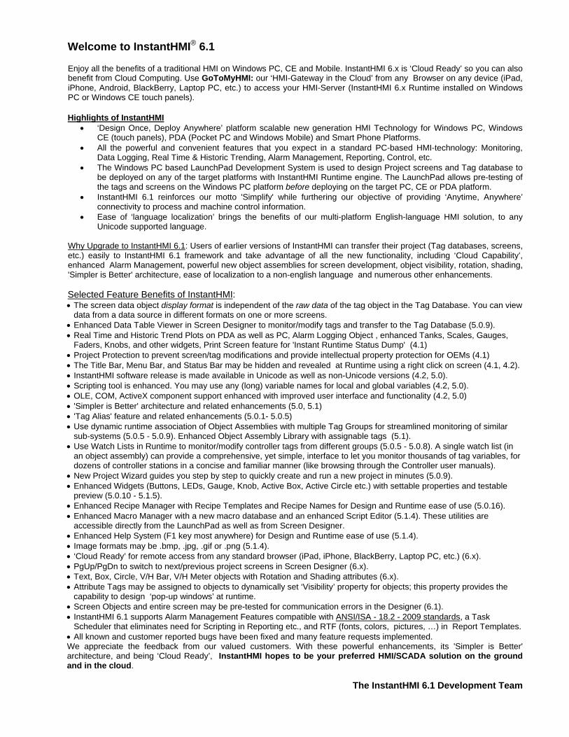
Welcome to InstantHMI® 6.1 Enjoy all the benefits of a traditional HMI on Windows PC, CE and Mobile. InstantHMI 6.x is ‘Cloud Ready’ so you can also benefit from Cloud Computing. Use GoToMyHMI: our ‘HMI-Gateway in the Cloud’ from any Browser on any device (iPad, iPhone, Android, BlackBerry, Laptop PC, etc.) to access your HMI-Server (InstantHMI 6.x Runtime installed on Windows PC or Windows CE touch panels). Highlights of InstantHMI
• ‘Design Once, Deploy Anywhere’ platform scalable new generation HMI Technology for Windows PC, Windows CE (touch panels), PDA (Pocket PC and Windows Mobile) and Smart Phone Platforms.
• All the powerful and convenient features that you expect in a standard PC-based HMI-technology: Monitoring, Data Logging, Real Time & Historic Trending, Alarm Management, Reporting, Control, etc.
• The Windows PC based LaunchPad Development System is used to design Project screens and Tag database to be deployed on any of the target platforms with InstantHMI Runtime engine. The LaunchPad allows pre-testing of the tags and screens on the Windows PC platform before deploying on the target PC, CE or PDA platform.
• InstantHMI 6.1 reinforces our motto 'Simplify' while furthering our objective of providing ‘Anytime, Anywhere’ connectivity to process and machine control information.
• Ease of ‘language localization’ brings the benefits of our multi-platform English-language HMI solution, to any Unicode supported language.
Why Upgrade to InstantHMI 6.1: Users of earlier versions of InstantHMI can transfer their project (Tag databases, screens, etc.) easily to InstantHMI 6.1 framework and take advantage of all the new functionality, including ‘Cloud Capability’, enhanced Alarm Management, powerful new object assemblies for screen development, object visibility, rotation, shading, 'Simpler is Better' architecture, ease of localization to a non-english language and numerous other enhancements. Selected Feature Benefits of InstantHMI: • The screen data object display format is independent of the raw data of the tag object in the Tag Database. You can view
data from a data source in different formats on one or more screens. • Enhanced Data Table Viewer in Screen Designer to monitor/modify tags and transfer to the Tag Database (5.0.9). • Real Time and Historic Trend Plots on PDA as well as PC, Alarm Logging Object , enhanced Tanks, Scales, Gauges,
Faders, Knobs, and other widgets, Print Screen feature for 'Instant Runtime Status Dump' (4.1) • Project Protection to prevent screen/tag modifications and provide intellectual property protection for OEMs (4.1) • The Title Bar, Menu Bar, and Status Bar may be hidden and revealed at Runtime using a right click on screen (4.1, 4.2). • InstantHMI software release is made available in Unicode as well as non-Unicode versions (4.2, 5.0). • Scripting tool is enhanced. You may use any (long) variable names for local and global variables (4.2, 5.0). • OLE, COM, ActiveX component support enhanced with improved user interface and functionality (4.2, 5.0) • 'Simpler is Better' architecture and related enhancements (5.0, 5.1) • 'Tag Alias' feature and related enhancements (5.0.1- 5.0.5) • Use dynamic runtime association of Object Assemblies with multiple Tag Groups for streamlined monitoring of similar
sub-systems (5.0.5 - 5.0.9). Enhanced Object Assembly Library with assignable tags (5.1). • Use Watch Lists in Runtime to monitor/modify controller tags from different groups (5.0.5 - 5.0.8). A single watch list (in
an object assembly) can provide a comprehensive, yet simple, interface to let you monitor thousands of tag variables, for dozens of controller stations in a concise and familiar manner (like browsing through the Controller user manuals).
• New Project Wizard guides you step by step to quickly create and run a new project in minutes (5.0.9). • Enhanced Widgets (Buttons, LEDs, Gauge, Knob, Active Box, Active Circle etc.) with settable properties and testable
preview (5.0.10 - 5.1.5). • Enhanced Recipe Manager with Recipe Templates and Recipe Names for Design and Runtime ease of use (5.0.16). • Enhanced Macro Manager with a new macro database and an enhanced Script Editor (5.1.4). These utilities are
accessible directly from the LaunchPad as well as from Screen Designer. • Enhanced Help System (F1 key most anywhere) for Design and Runtime ease of use (5.1.4). • Image formats may be .bmp, .jpg, .gif or .png (5.1.4). • ‘Cloud Ready’ for remote access from any standard browser (iPad, iPhone, BlackBerry, Laptop PC, etc.) (6.x). • PgUp/PgDn to switch to next/previous project screens in Screen Designer (6.x). • Text, Box, Circle, V/H Bar, V/H Meter objects with Rotation and Shading attributes (6.x). • Attribute Tags may be assigned to objects to dynamically set ‘Visibility’ property for objects; this property provides the
capability to design ‘pop-up windows’ at runtime. • Screen Objects and entire screen may be pre-tested for communication errors in the Designer (6.1). • InstantHMI 6.1 supports Alarm Management Features compatible with ANSI/ISA - 18.2 - 2009 standards, a Task
Scheduler that eliminates need for Scripting in Reporting etc., and RTF (fonts, colors, pictures, …) in Report Templates. • All known and customer reported bugs have been fixed and many feature requests implemented. We appreciate the feedback from our valued customers. With these powerful enhancements, its 'Simpler is Better' architecture, and being ‘Cloud Ready’, InstantHMI hopes to be your preferred HMI/SCADA solution on the ground and in the cloud.
The InstantHMI 6.1 Development Team


SOFTWARE HORIZONS INC. InstantHMI® PROGRAM LICENSE AGREEMENT
YOU SHOULD CAREFULLY READ THE FOLLOWING TERMS AND CONDITIONS BEFORE USING THIS PACKAGE. IF YOU DO NOT AGREE WITH THEM, PROMPTLY RETURN THE PACKAGE UNUSED WITHIN 10 DAYS AND YOUR MONEY WILL BE REFUNDED. USING THIS PACKAGE INDICATES YOUR ACCEPTANCE OF THESE TERMS AND CONDITIONS. Software Horizons Inc. (SH) provides InstantHMI (the "Program") and licenses its use pursuant to license agreements. You assume responsibility for the selection of the Program to achieve your intended results, and for the installation, use, and results obtained from the Program. You may a) Install and operate the Program on a single computer. b) Transfer the Program, subject to the terms of this license, to another party if the other party agrees to accept the terms and conditions of this Agreement. If you transfer the Program, you must at the same time either transfer all copies whether in printed or machine-readable form to the same party or destroy any copies not transferred. You may not: a) use, copy, modify or transfer the Program, or any copy, in whole or in part, except as expressly provided for in this license. b) provide or allow use of the Program in any network, time sharing, multiple CPU, or multiple-user arrangements. c) grant sub-licenses or other rights in the Program. d) reproduce the documentation. IF YOU TRANSFER POSSESSION OF THE PROGRAM OR ANY COPY TO ANOTHER PARTY, YOUR LICENSE IS AUTOMATICALLY TERMINATED. TERM: This license is effective until terminated. You may terminate it at any other time by destroying the Program together with all copies in any form. It will also terminate upon conditions set forth elsewhere in this Agreement. You agree upon such termination to destroy the Program together with all copies in any form. No refunds will be made on termination of license. LIMITED WARRANTY: SH warrants the diskette(s) and computer chips on which the Program is furnished to be free from defects in materials and workmanship under normal use for a period of ninety (90) days from the date of delivery to you as evidenced by a copy of your receipt. However, SH does not warrant that the Program will meet your requirements or that the operation of the Program will be uninterrupted or error free. THE PROGRAM IS PROVIDED "AS IS" WITHOUT ANY WARRANTY, EXCEPT AS STATED ABOVE, OF ANY KIND, EITHER EXPRESSED OR IMPLIED, INCLUDING, BUT NOT LIMITED TO THE IMPLIED WARRANTIES OF MERCHANTABILITY AND FITNESS FOR A PARTICULAR PURPOSE. THE ENTIRE RISK AS TO THE QUALITY AND PERFORMANCE OF THE PROGRAM IS WITH YOU. LIMITATIONS OF REMEDIES: SH's entire liability and your exclusive remedy shall be: the replacement of any diskette(s) and/or chips not meeting SH's "Limited Warranty" and which is returned to SH with a copy of your receipt. IN NO EVENT WILL SH BE LIABLE TO YOU FOR DAMAGES, INCLUDING ANY LOST PROFITS, LOST MONIES OR OTHER INCIDENTAL OR CONSEQUENTIAL DAMAGES ARISING OUT OF THE USE OR INABILITY TO USE (INCLUDING BUT NOT LIMITED TO LOSS OF DATA OR DATA BEING RENDERED INACCURATE OR LOSSES SUSTAINED BY THIRD PARTIES OR A FAILURE OF THE PROGRAM TO OPERATE WITH PROGRAMS NOT DISTRIBUTED BY SH) SUCH PROGRAM EVEN IF SH HAS BEEN ADVISED OF THE POSSIBILITY OF SUCH DAMAGES, OR FOR ANY CLAIM BY ANY OTHER PARTY. SOME STATES DO NOT ALLOW THE LIMITATION OR EXCLUSION OF LIABILITY FOR INCIDENTAL OR CONSEQUENTIAL DAMAGES OR IMPLIED WARRANTIES SO THE ABOVE LIMITATION OR EXCLUSION MAY NOT, IN WHOLE OR IN PART, APPLY TO YOU. GENERAL: You may not sublicense, assign or transfer this license or the Program except as expressly provided in this Agreement. Any attempt otherwise to sublicense, assign, or transfer any of the rights, duties or obligations hereunder is void. This Agreement shall be governed by the laws of the Commonwealth of Massachusetts. Should you have any questions concerning this Agreement, you may contact SH by writing to Software Horizons Inc., 100 Treble Cove Road, N. Billerica, Massachusetts 01862. YOU ACKNOWLEDGE THAT YOU HAVE READ THIS AGREEMENT, UNDERSTAND IT AND AGREE TO BE BOUND BY ITS TERMS AND CONDITIONS. YOU FURTHER AGREE THAT IT IS THE COMPLETE AND EXCLUSIVE STATEMENT OF THE AGREEMENT BETWEEN US, WHICH SUPERSEDES ANY PROPOSAL OR PRIOR AGREEMENT, ORAL OR WRITTEN, AND ANY OTHER COMMUNICATIONS BETWEEN YOU AND SH RELATING TO THE SUBJECT MATTER OF THIS AGREEMENT. U.S. Government Restricted Rights. The SOFTWARE and documentation are provided with RESTRICTED RIGHTS. Use, duplication, or disclosure by the United States Government is subject to restrictions as set forth in subparagraph (c)(1)(ii) of The Rights in Technical Data and Computer Software clause at DFARS 252.227-7013 or subparagraphs (c)(1) and (2) of the Commercial Computer Software--Restricted Rights at 48 CFR 52.227-19, as applicable. Manufacturer is Software Horizons Inc., 100 Treble Cove Road, N. Billerica, MA 01862, USA.

Table of Contents
1 Quick Start Guide - Training Objectives ........................................................................................................................ 1-1 1.1 Introduction ............................................................................................................................................................ 1-1 1.2 Test Communications with Your PLC .................................................................................................................... 1-2
1.2.1 Step 1: Create New Project ............................................................................................................................ 1-2 1.2.2 Step 2: Define Data Source ............................................................................................................................ 1-2 1.2.3 Step 3: Identify Tags ....................................................................................................................................... 1-3 1.2.4 Step 4: Design Screen .................................................................................................................................... 1-4 1.2.5 Step 5: Test Screen in Runtime ...................................................................................................................... 1-4
1.3 Sample Application: Water Supply System ............................................................................................................ 1-5 1.4 InstantHMI Solution: Water Supply System (PC) ................................................................................................... 1-5
1.4.1 System Status - Stage 1 (PC) ......................................................................................................................... 1-7 1.4.2 System Status - Stage 2 (PC) ......................................................................................................................... 1-15 1.4.3 System Status - Stage 3 (PC) ......................................................................................................................... 1-18 1.4.4 System Status - Stage 4 (PC) ......................................................................................................................... 1-20 1.4.5 System Status (PC) ........................................................................................................................................ 1-21 1.4.6 Tank Level Trends (PC) .................................................................................................................................. 1-22 1.4.7 Water Supply System Solution - PC Runtime Platform ................................................................................... 1-24
1.5 InstantHMI Solution: Water Supply System (PPC) ................................................................................................ 1-29 1.6 InstantHMI Solution: Water Supply System (CE) ................................................................................................... 1-31
A. Solution for Your Controllers .................................................................................................................................... A.1-1 A.1 Solution for Allen-Bradley Controllers .............................................................................................................. A.1-1
A.1.1 Allen-Bradley Serial DF1 Protocol .............................................................................................................. A.1-1 A.1.2 Allen-Bradley EtherNet/IP (PCCC DF1) Protocol ....................................................................................... A.1-3 A.1.3 Allen-Bradley EtherNet/IP Protocol ............................................................................................................ A.1-5 A.1.4 Allen-Bradley Communications (Protocols and Drivers) ............................................................................. A.1-6
A.2 Solution for Modbus Controllers ....................................................................................................................... A.2-1 A.2.1 Modbus Serial RTU/Ascii Protocol ............................................................................................................. A.2-1 A.2.2 Modbus TCP Protocol ................................................................................................................................ A.2-3 A.2.3 Modbus Communications (Protocols and Drivers) ..................................................................................... A.2-4
A.3 Solution for Koyo - DirectLogic PLC ................................................................................................................. A.3-1 A.3.1 Koyo Direct Net/CCM2 Serial Protocol ....................................................................................................... A.3-1 A.3.2 Koyo Ecom - Ethernet Protocol .................................................................................................................. A.3-3 A.3.3 Koyo / DirectLogic Communications (Protocols and Drivers) ..................................................................... A.3-4
A.4 Solution for Unitronics PLC .............................................................................................................................. A.4-1 A.4.1 Unitronics Serial Protocol ........................................................................................................................... A.4-1 A.4.2 Unitronics Ethernet Protocol ....................................................................................................................... A.4-3 A.4.3 Unitronics (Protocols and Drivers) .............................................................................................................. A.4-5
A.5 Solution for Siemens PLC ................................................................................................................................ A.5-1 A.5.1 Siemens - PPI Protocol .............................................................................................................................. A.5-1 A.5.2 Siemens - MPI Protocol .............................................................................................................................. A.5-3 A.5.3 Texas Instruments PLC .............................................................................................................................. A.5-5 A.5.4 Siemens Communications (Protocols and Drivers) .................................................................................... A.5-6 A.5.5 TI Communication Protocol – Driver 01 ...................................................................................................... A.5-10
A.6 Solution for Mitsubishi Controllers .................................................................................................................... A.6-1 A.6.1 Mitsubishi Serial Protocol ........................................................................................................................... A.6-1 A.6.2 Mitsubishi Communications (Protocols and Drivers) .................................................................................. A.6-3 A.6.3 InstantHMI Drivers for Mitsubishi Controllers ............................................................................................. A.6-7
A.7 InstantHMI Designed for GPS Application ....................................................................................................... A.7-1 A.7.1 Introduction to GPS .................................................................................................................................... A.7-1 A.7.2 GPS Serial Protocol (NMEA) ...................................................................................................................... A.7-1 A.7.3 Example: Pipeline Monitoring Application .................................................................................................. A.7-4 A.7.4 Logged File in CSV Format ........................................................................................................................ A.7-8 A.7.5 Sample Tag Database ................................................................................................................................ A.7-9
A.8 Solution for SeaLevel SeaPAC R9 Onboard I/O .............................................................................................. A.8-1 A.8.1 SeaLevel SeaPAC R9 Onboard I/O ........................................................................................................... A.8-1 A.8.2 SeaLevel SeaPAC R9 Onboard I/O Driver ................................................................................................. A.8-3
A.9 Solution for Toshiba Controllers ....................................................................................................................... A.9-1 A.9.1 Toshiba Serial Protocol .............................................................................................................................. A.9-1 A.9.2 Toshiba Ethernet (Modbus TCP) Protocol .................................................................................................. A.9-3 A.9.3 Toshiba Communications (Protocols and Drivers) ..................................................................................... A.9-4

InstantHMI: Quick Start Guide Page 1-1
InstantHMI: Copyright © 2000-2012 Software Horizons Inc. 6.1 – 20Jun2012
1 Quick Start Guide - Training Objectives 1.1 Introduction
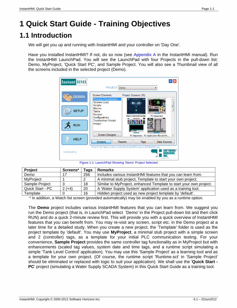
We will get you up and running with InstantHMI and your controller on 'Day One'. Have you installed InstantHMI? If not, do so now (see Appendix A in the InstantHMI manual). Run the InstantHMI LaunchPad. You will see the LaunchPad with four Projects in the pull-down list: Demo, MyProject, 'Quick Start PC', and Sample Project. You will also see a Thumbnail view of all the screens included in the selected project (Demo).
Figure 1-1: LaunchPad Showing 'Demo' Project Selected
Project Screens* Tags Remarks Demo 17 256 Includes various InstantHMI features that you can learn from. MyProject 1 2 A minimal stub project, Template to start your own project. Sample Project 3 18 Similar to MyProject, enhanced Template to start your own project. Quick Start - PC 2 (+4) 20 A 'Water Supply System' application used as a training tool. Template 0 16 Hidden project used as new project template by 'default'.
* In addition, a Watch list screen (provided automatically) may be enabled by you as a runtime option. The Demo project includes various InstantHMI features that you can learn from. We suggest you run the Demo project (that is, in LaunchPad select 'Demo' in the Project pull-down list and then click RUN) and do a quick 2-minute review first. This will provide you with a quick overview of InstantHMI features that you can benefit from. You may re-visit any screen, script etc. in the Demo project at a later time for a detailed study. When you create a new project, the 'Template' folder is used as the project template by 'default'. You may use MyProject, a minimal stub project with a simple screen and 2 (controller) tags, as a template for your initial PLC communication testing. For your convenience, Sample Project provides the same controller tag functionality as in MyProject but with enhancements (scaled tag values, system date and time tags, and a runtime script simulating a simple 'Tank Level Control' application). You may use this 'Sample Project' as a learning tool and as a template for your own project. (Of course, the runtime script 'Runtime.sct' in 'Sample Project' should be eliminated or replaced with logic to suit your application). We shall use the 'Quick Start - PC' project (simulating a Water Supply SCADA System) in this Quick Start Guide as a training tool.
InstantHMI: Quick Start Guide Page 1-2
InstantHMI: Copyright © 2000-2012 Software Horizons Inc. 6.1 – 20Jun2012
1.2 Test Communications with Your PLC 1.2.1 Step 1: Create New Project
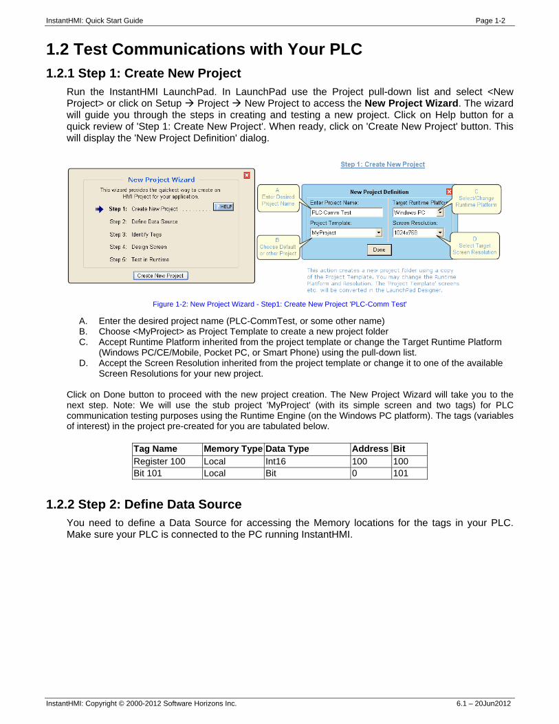
Run the InstantHMI LaunchPad. In LaunchPad use the Project pull-down list and select <New Project> or click on Setup Project New Project to access the New Project Wizard. The wizard will guide you through the steps in creating and testing a new project. Click on Help button for a quick review of 'Step 1: Create New Project'. When ready, click on 'Create New Project' button. This will display the 'New Project Definition' dialog.
Figure 1-2: New Project Wizard - Step1: Create New Project 'PLC-Comm Test'
A. Enter the desired project name (PLC-CommTest, or some other name) B. Choose <MyProject> as Project Template to create a new project folder C. Accept Runtime Platform inherited from the project template or change the Target Runtime Platform
(Windows PC/CE/Mobile, Pocket PC, or Smart Phone) using the pull-down list. D. Accept the Screen Resolution inherited from the project template or change it to one of the available
Screen Resolutions for your new project. Click on Done button to proceed with the new project creation. The New Project Wizard will take you to the next step. Note: We will use the stub project 'MyProject' (with its simple screen and two tags) for PLC communication testing purposes using the Runtime Engine (on the Windows PC platform). The tags (variables of interest) in the project pre-created for you are tabulated below.
Tag Name Memory Type Data Type Address Bit Register 100 Local Int16 100 100 Bit 101 Local Bit 0 101
1.2.2 Step 2: Define Data Source You need to define a Data Source for accessing the Memory locations for the tags in your PLC. Make sure your PLC is connected to the PC running InstantHMI.
InstantHMI: Quick Start Guide Page 1-3
InstantHMI: Copyright © 2000-2012 Software Horizons Inc. 6.1 – 20Jun2012
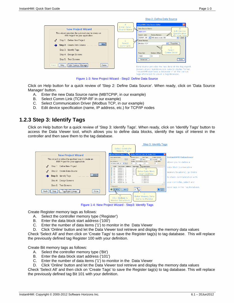
Figure 1-3: New Project Wizard - Step2: Define Data Source
Click on Help button for a quick review of 'Step 2: Define Data Source'. When ready, click on 'Data Source Manager' button.
A. Enter the new Data Source name (MBTCPIP, in our example) B. Select Comm Link (TCP/IP-RF in our example) C. Select Communication Driver (Modbus TCP, in our example) D. Edit device specification (name, IP address, etc.) for TCP/IP nodes
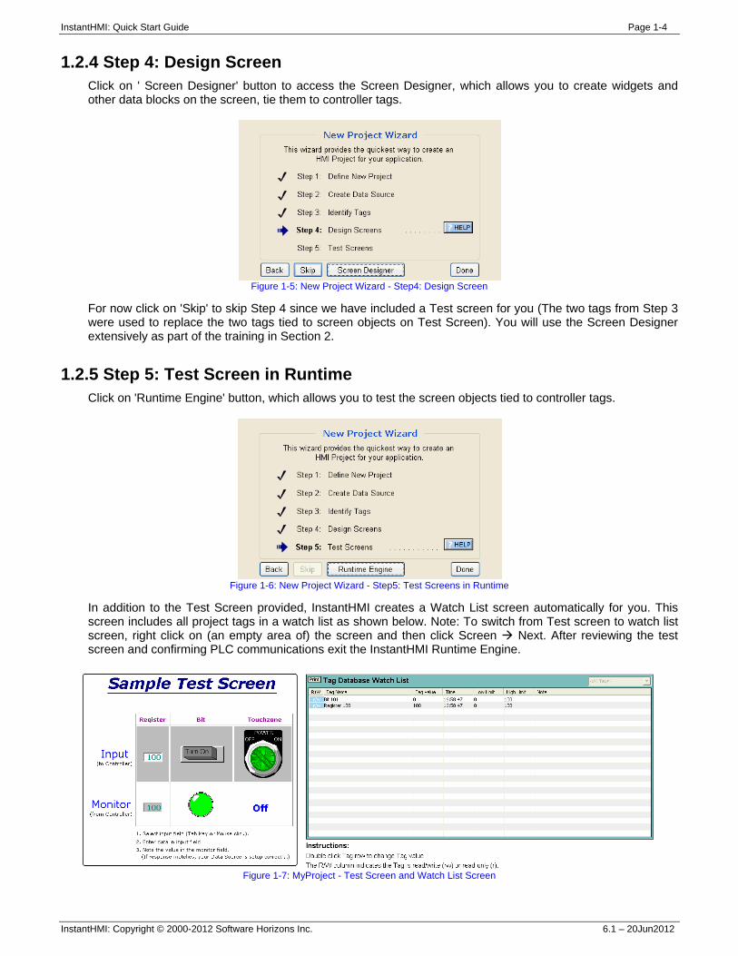
1.2.3 Step 3: Identify Tags Click on Help button for a quick review of 'Step 3: Identify Tags'. When ready, click on 'Identify Tags' button to access the Data Viewer tool, which allows you to define data blocks, identify the tags of interest in the controller and then save them to the tag database.
Figure 1-4: New Project Wizard - Step3: Identify Tags
Create Register memory tags as follows: A. Select the controller memory type ('Register') B. Enter the data block start address ('100') C. Enter the number of data items ('1') to monitor in the Data Viewer D. Click 'Online' button and let the Data Viewer tool retrieve and display the memory data values
Check 'Select All' and then click on 'Create Tags' to save the Register tag(s) to tag database. This will replace the previously defined tag Register 100 with your definition. Create Bit memory tags as follows:
A. Select the controller memory type ('Bit') B. Enter the data block start address ('101') C. Enter the number of data items ('1') to monitor in the Data Viewer D. Click 'Online' button and let the Data Viewer tool retrieve and display the memory data values
Check 'Select All' and then click on 'Create Tags' to save the Register tag(s) to tag database. This will replace the previously defined tag Bit 101 with your definition.
InstantHMI: Quick Start Guide Page 1-4
InstantHMI: Copyright © 2000-2012 Software Horizons Inc. 6.1 – 20Jun2012
1.2.4 Step 4: Design Screen Click on ' Screen Designer' button to access the Screen Designer, which allows you to create widgets and other data blocks on the screen, tie them to controller tags.
Figure 1-5: New Project Wizard - Step4: Design Screen
For now click on 'Skip' to skip Step 4 since we have included a Test screen for you (The two tags from Step 3 were used to replace the two tags tied to screen objects on Test Screen). You will use the Screen Designer extensively as part of the training in Section 2.
1.2.5 Step 5: Test Screen in Runtime Click on 'Runtime Engine' button, which allows you to test the screen objects tied to controller tags.
Figure 1-6: New Project Wizard - Step5: Test Screens in Runtime
In addition to the Test Screen provided, InstantHMI creates a Watch List screen automatically for you. This screen includes all project tags in a watch list as shown below. Note: To switch from Test screen to watch list screen, right click on (an empty area of) the screen and then click Screen Next. After reviewing the test screen and confirming PLC communications exit the InstantHMI Runtime Engine.
Figure 1-7: MyProject - Test Screen and Watch List Screen
InstantHMI: Quick Start Guide Page 1-5
InstantHMI: Copyright © 2000-2012 Software Horizons Inc. 6.1 – 20Jun2012
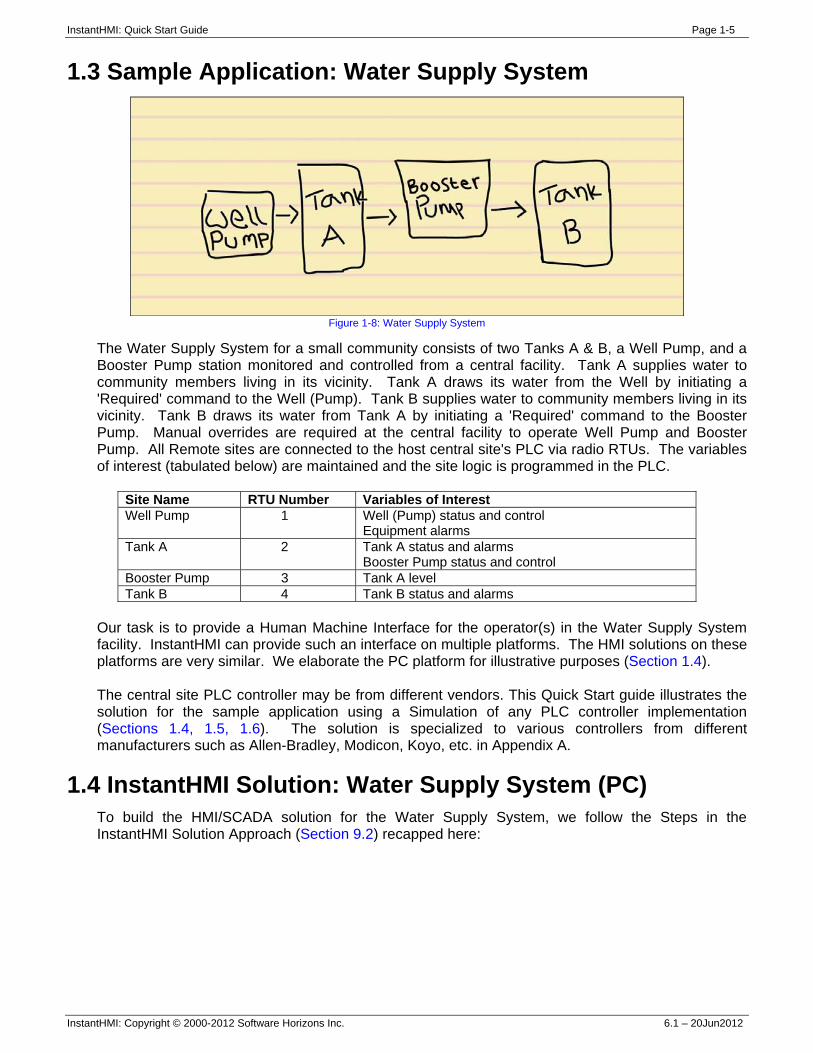
1.3 Sample Application: Water Supply System
Figure 1-8: Water Supply System
The Water Supply System for a small community consists of two Tanks A & B, a Well Pump, and a Booster Pump station monitored and controlled from a central facility. Tank A supplies water to community members living in its vicinity. Tank A draws its water from the Well by initiating a 'Required' command to the Well (Pump). Tank B supplies water to community members living in its vicinity. Tank B draws its water from Tank A by initiating a 'Required' command to the Booster Pump. Manual overrides are required at the central facility to operate Well Pump and Booster Pump. All Remote sites are connected to the host central site's PLC via radio RTUs. The variables of interest (tabulated below) are maintained and the site logic is programmed in the PLC.
Site Name RTU Number Variables of Interest Well Pump 1 Well (Pump) status and control
Equipment alarms Tank A 2 Tank A status and alarms
Booster Pump status and control Booster Pump 3 Tank A level Tank B 4 Tank B status and alarms
Our task is to provide a Human Machine Interface for the operator(s) in the Water Supply System facility. InstantHMI can provide such an interface on multiple platforms. The HMI solutions on these platforms are very similar. We elaborate the PC platform for illustrative purposes (Section 1.4). The central site PLC controller may be from different vendors. This Quick Start guide illustrates the solution for the sample application using a Simulation of any PLC controller implementation (Sections 1.4, 1.5, 1.6). The solution is specialized to various controllers from different manufacturers such as Allen-Bradley, Modicon, Koyo, etc. in Appendix A.
1.4 InstantHMI Solution: Water Supply System (PC) To build the HMI/SCADA solution for the Water Supply System, we follow the Steps in the InstantHMI Solution Approach (Section 9.2) recapped here:
InstantHMI: Quick Start Guide Page 1-6
InstantHMI: Copyright © 2000-2012 Software Horizons Inc. 6.1 – 20Jun2012
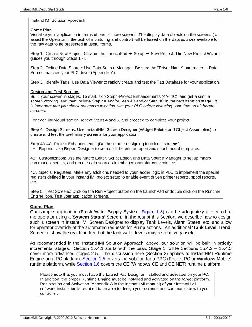
InstantHMI Solution Approach Game Plan Visualize your application in terms of one or more screens. The display data objects on the screens (to assist the Operator in the task of monitoring and control) will be based on the data sources available for the raw data to be presented in useful forms. Step 1. Create New Project: Click on the LaunchPad Setup New Project. The New Project Wizard guides you through Steps 1 - 5. Step 2. Define Data Source: Use Data Source Manager. Be sure the "Driver Name" parameter in Data Source matches your PLC driver (Appendix A). Step 3. Identify Tags: Use Data Viewer to rapidly create and test the Tag Database for your application. Design and Test Screens Build your screen in stages. To start, skip Step4-Project Enhancements (4A- 4C), and get a simple screen working, and then include Step 4A and/or Step 4B and/or Step 4C in the next iteration stage. It is important that you check out communication with your PLC before investing your time on elaborate screens. For each individual screen, repeat Steps 4 and 5, and proceed to complete your project. Step 4. Design Screens: Use InstantHMI Screen Designer (Widget Palette and Object Assemblies) to create and test the preliminary screens for your application. Step 4A-4C. Project Enhancements: (Do these after designing functional screens) 4A. Reports: Use Report Designer to create all the printer report and spool record templates. 4B. Customization: Use the Macro Editor, Script Editor, and Data Source Manager to set up macro commands, scripts, and remote data sources to enhance operator convenience. 4C. Special Registers: Make any additions needed to your ladder logic in PLC to implement the special registers defined in your InstantHMI project setup to enable event driven printer reports, spool reports, etc. Step 5. Test Screens: Click on the Run Project button on the LaunchPad or double click on the Runtime Engine icon. Test your application screens. Game Plan Our sample application (Fresh Water Supply System, Figure 1-8) can be adequately presented to the operator using a 'System Status' Screen. In the rest of this Section, we describe how to design such a screen in InstantHMI Screen Designer to display Tank Levels, Alarm States, etc. and allow for operator override of the automated requests for Pump actions. An additional 'Tank Level Trend' Screen to show the real time trend of the tank water levels may also be very useful. As recommended in the 'InstantHMI Solution Approach' above, our solution will be built in orderly incremental stages. Section 15.4.1 starts with the basic Stage 1, while Sections 15.4.2 – 15.4.5 cover more advanced stages 2-5. The discussion here (Section 2) applies to InstantHMI Runtime Engine on a PC platform. Section 1.5 covers the solution for a PPC (Pocket PC or Windows Mobile) runtime platform, while Section 1.6 covers the CE (Windows CE and CE.NET) runtime platform.
Please note that you must have the LaunchPad Designer installed and activated on your PC. In addition, the proper Runtime Engine must be installed and activated on the target platform. Registration and Activation (Appendix A in the InstantHMI manual) of your InstantHMI software installation is required to be able to design your screens and communicate with your controller.
InstantHMI: Quick Start Guide Page 1-7
InstantHMI: Copyright © 2000-2012 Software Horizons Inc. 6.1 – 20Jun2012
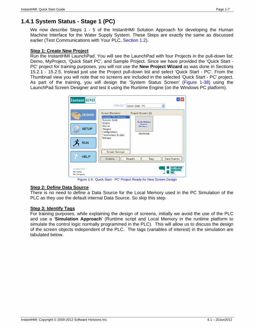
1.4.1 System Status - Stage 1 (PC) We now describe Steps 1 - 5 of the InstantHMI Solution Approach for developing the Human Machine Interface for the Water Supply System. These Steps are exactly the same as discussed earlier (Test Communications with Your PLC, Section 1.2). Step 1: Create New Project Run the InstantHMI LaunchPad. You will see the LaunchPad with four Projects in the pull-down list: Demo, MyProject, 'Quick Start PC', and Sample Project. Since we have provided the 'Quick Start - PC' project for training purposes, you will not use the New Project Wizard as was done in Sections 15.2.1 - 15.2.5. Instead just use the Project pull-down list and select 'Quick Start - PC'. From the Thumbnail view you will note that no screens are included in the selected 'Quick Start - PC' project. As part of the training, you will design the 'System Status Screen' (Figure 1-38) using the LaunchPad Screen Designer and test it using the Runtime Engine (on the Windows PC platform).
Figure 1-9: 'Quick Start - PC' Project Ready for New Screen Design
Step 2: Define Data Source There is no need to define a Data Source for the Local Memory used in the PC Simulation of the PLC as they use the default internal Data Source. So skip this step. Step 3: Identify Tags For training purposes, while explaining the design of screens, initially we avoid the use of the PLC and use a 'Simulation Approach' (Runtime script and Local Memory in the runtime platform to simulate the control logic normally programmed in the PLC). This will allow us to discuss the design of the screen objects independent of the PLC. The tags (variables of interest) in the simulation are tabulated below.
InstantHMI: Quick Start Guide Page 1-8
InstantHMI: Copyright © 2000-2012 Software Horizons Inc. 6.1 – 20Jun2012
Tag Name Data Type
Data Format
Memory Type
Memory Address
Tag Group Membership
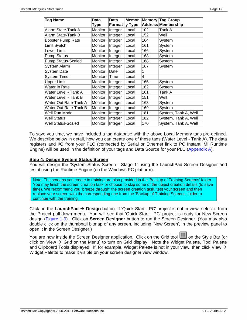
Alarm State-Tank A Monitor Integer Local 102 Tank A Alarm State-Tank B Monitor Integer Local 152 Well Booster Pump Rate Monitor Integer Local 164 System Limit Switch Monitor Integer Local 161 System Lower Limit Monitor Integer Local 166 System Pump Status Monitor Integer Local 168 System Pump Status-Scaled Monitor Integer Local 168 System System Alarm Monitor Integer Local 167 System System Date Monitor Date Local 1 System Time Monitor Time Local 4 Upper Limit Monitor Integer Local 165 System Water In Rate Monitor Integer Local 162 System Water Level - Tank A Monitor Integer Local 101 Tank A Water Level - Tank B Monitor Integer Local 151 Well Water Out Rate-Tank A Monitor Integer Local 163 System Water Out Rate-Tank B Monitor Integer Local 169 System Well Run Mode Monitor Integer Local 181 System, Tank A, Well Well Status Monitor Integer Local 182 System, Tank A, Well Well Status-Scaled Monitor Integer Local 170 System, Tank A, Well
To save you time, we have included a tag database with the above Local Memory tags pre-defined. We describe below in detail, how you can create one of these tags (Water Level - Tank A). The data registers and I/O from your PLC (connected by Serial or Ethernet link to PC InstantHMI Runtime Engine) will be used in the definition of your tags and Data Source for your PLC (Appendix A). Step 4: Design System Status Screen You will design the 'System Status Screen - Stage 1' using the LaunchPad Screen Designer and test it using the Runtime Engine (on the Windows PC platform).
Note: The screens you create in training are also provided in the 'Backup of Training Screens' folder. You may finish the screen creation task or choose to skip some of the object creation details (to save time). We recommend you 'breeze through' the screen creation task, test your screen and then replace your screen with the corresponding one from the 'Backup of Training Screens' folder to continue with the training.
Click on the LaunchPad Design button. If 'Quick Start - PC' project is not in view, select it from the Project pull-down menu. You will see that 'Quick Start - PC' project is ready for New Screen design (Figure 1-9). Click on Screen Designer button to run the Screen Designer. (You may also double click on the thumbnail bitmap of any screen, including 'New Screen', in the preview panel to open it in the Screen Designer.)
You are now inside the Screen Designer application. Click on the Grid tool on the Style Bar (or click on View Grid on the Menu) to turn on Grid display. Note the Widget Palette, Tool Palette and Clipboard Tools displayed. If, for example, Widget Palette is not in your view, then click View Widget Palette to make it visible on your screen designer view window.
InstantHMI: Quick Start Guide Page 1-9
InstantHMI: Copyright © 2000-2012 Software Horizons Inc. 6.1 – 20Jun2012
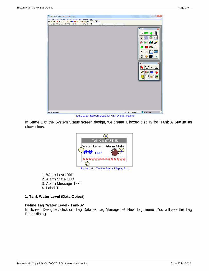
Figure 1-10: Screen Designer with Widget Palette
In Stage 1 of the System Status screen design, we create a boxed display for 'Tank A Status' as shown here.
Figure 1-11: Tank A Status Display Box
1. Water Level '##' 2. Alarm State LED 3. Alarm Message Text 4. Label Text
1. Tank Water Level (Data Object) Define Tag 'Water Level - Tank A' In Screen Designer, click on 'Tag Data Tag Manager New Tag' menu. You will see the Tag Editor dialog.
InstantHMI: Quick Start Guide Page 1-10
InstantHMI: Copyright © 2000-2012 Software Horizons Inc. 6.1 – 20Jun2012
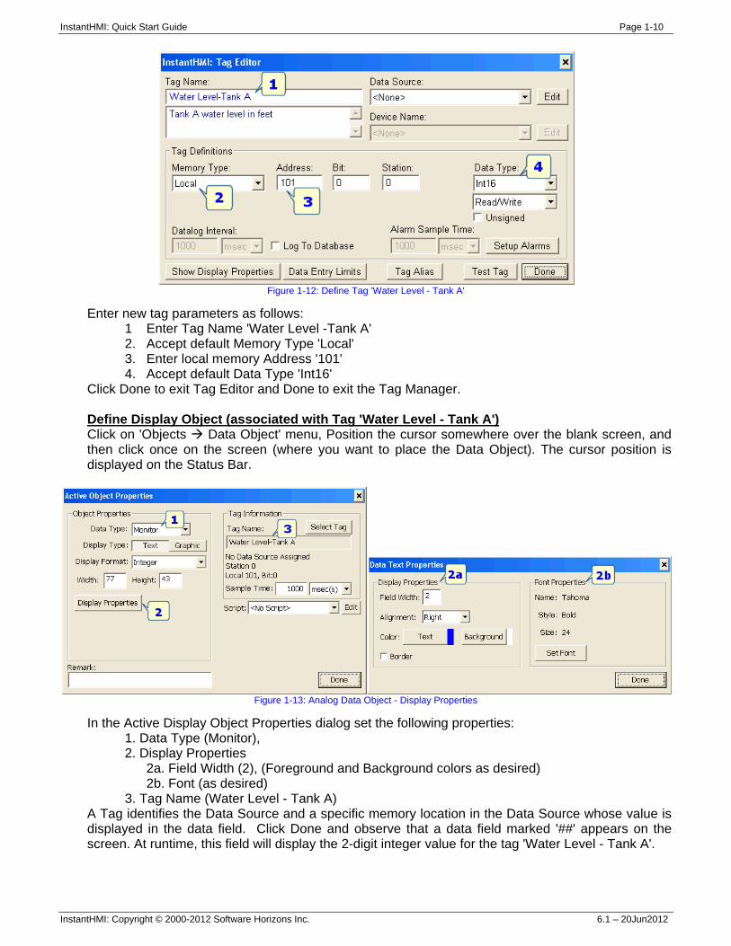
Figure 1-12: Define Tag 'Water Level - Tank A'
Enter new tag parameters as follows: 1 Enter Tag Name 'Water Level -Tank A' 2. Accept default Memory Type 'Local' 3. Enter local memory Address '101' 4. Accept default Data Type 'Int16'
Click Done to exit Tag Editor and Done to exit the Tag Manager. Define Display Object (associated with Tag 'Water Level - Tank A') Click on 'Objects Data Object' menu, Position the cursor somewhere over the blank screen, and then click once on the screen (where you want to place the Data Object). The cursor position is displayed on the Status Bar.
Figure 1-13: Analog Data Object - Display Properties
In the Active Display Object Properties dialog set the following properties: 1. Data Type (Monitor), 2. Display Properties
2a. Field Width (2), (Foreground and Background colors as desired) 2b. Font (as desired)
3. Tag Name (Water Level - Tank A) A Tag identifies the Data Source and a specific memory location in the Data Source whose value is displayed in the data field. Click Done and observe that a data field marked '##' appears on the screen. At runtime, this field will display the 2-digit integer value for the tag 'Water Level - Tank A'.
InstantHMI: Quick Start Guide Page 1-11
InstantHMI: Copyright © 2000-2012 Software Horizons Inc. 6.1 – 20Jun2012
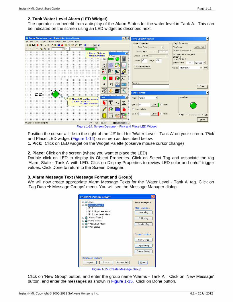
2. Tank Water Level Alarm (LED Widget) The operator can benefit from a display of the Alarm Status for the water level in Tank A. This can be indicated on the screen using an LED widget as described next.
Figure 1-14: Screen Designer - Pick and Place LED Widget
Position the cursor a little to the right of the '##' field for 'Water Level - Tank A' on your screen. 'Pick and Place' LED widget (Figure 1-14) on screen as described below: 1. Pick: Click on LED widget on the Widget Palette (observe mouse cursor change) 2. Place: Click on the screen (where you want to place the LED) Double click on LED to display its Object Properties. Click on Select Tag and associate the tag 'Alarm State - Tank A' with LED. Click on Display Properties to review LED color and on/off trigger values. Click Done to return to the Screen Designer. 3. Alarm Message Text (Message Format and Group) We will now create appropriate Alarm Message Texts for the 'Water Level - Tank A' tag. Click on 'Tag Data Message Groups' menu. You will see the Message Manager dialog.
Figure 1-15: Create Message Group
Click on 'New Group' button, and enter the group name 'Alarms - Tank A'. Click on 'New Message' button, and enter the messages as shown in Figure 1-15. Click on Done button.
InstantHMI: Quick Start Guide Page 1-12
InstantHMI: Copyright © 2000-2012 Software Horizons Inc. 6.1 – 20Jun2012
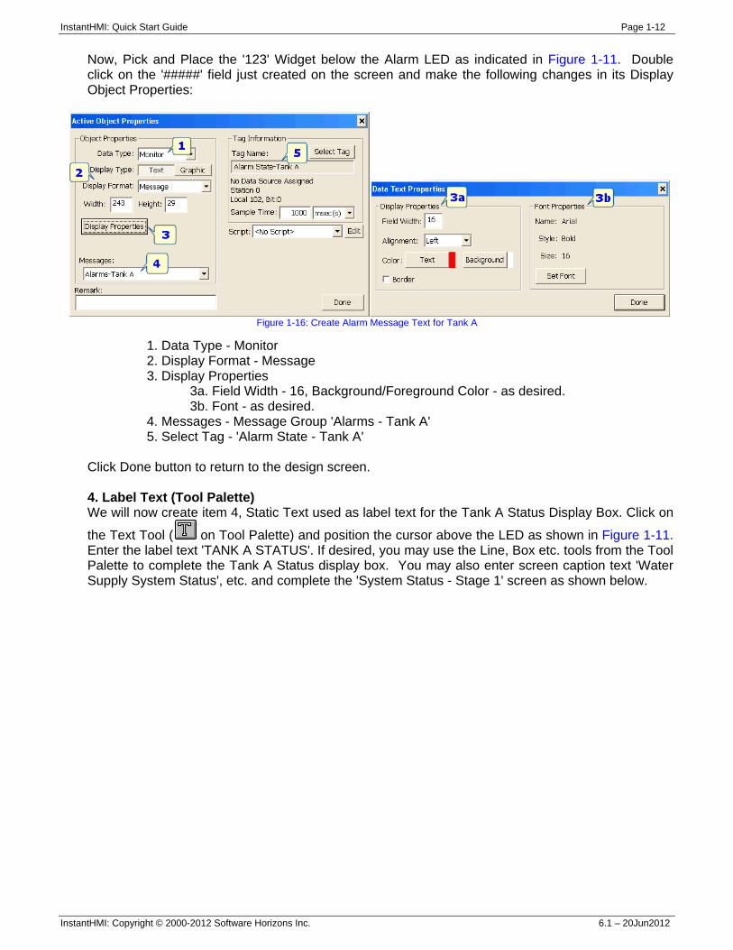
Now, Pick and Place the '123' Widget below the Alarm LED as indicated in Figure 1-11. Double click on the '#####' field just created on the screen and make the following changes in its Display Object Properties:
Figure 1-16: Create Alarm Message Text for Tank A
1. Data Type - Monitor 2. Display Format - Message 3. Display Properties
3a. Field Width - 16, Background/Foreground Color - as desired. 3b. Font - as desired.
4. Messages - Message Group 'Alarms - Tank A' 5. Select Tag - 'Alarm State - Tank A'
Click Done button to return to the design screen. 4. Label Text (Tool Palette) We will now create item 4, Static Text used as label text for the Tank A Status Display Box. Click on
the Text Tool ( on Tool Palette) and position the cursor above the LED as shown in Figure 1-11. Enter the label text 'TANK A STATUS'. If desired, you may use the Line, Box etc. tools from the Tool Palette to complete the Tank A Status display box. You may also enter screen caption text 'Water Supply System Status', etc. and complete the 'System Status - Stage 1' screen as shown below.
InstantHMI: Quick Start Guide Page 1-13
InstantHMI: Copyright © 2000-2012 Software Horizons Inc. 6.1 – 20Jun2012
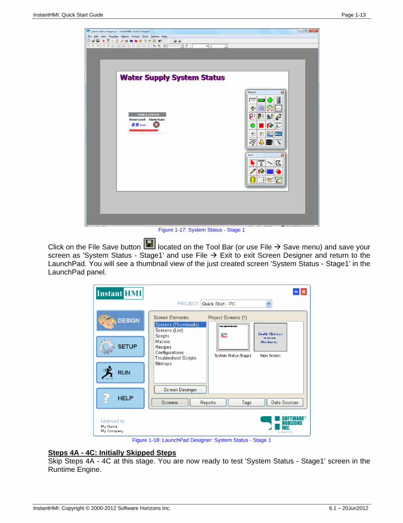
Figure 1-17: System Status - Stage 1
Click on the File Save button located on the Tool Bar (or use File Save menu) and save your screen as 'System Status - Stage1' and use File Exit to exit Screen Designer and return to the LaunchPad. You will see a thumbnail view of the just created screen 'System Status - Stage1' in the LaunchPad panel.
Figure 1-18: LaunchPad Designer: System Status - Stage 1
Steps 4A - 4C: Initially Skipped Steps Skip Steps 4A - 4C at this stage. You are now ready to test 'System Status - Stage1' screen in the Runtime Engine.
InstantHMI: Quick Start Guide Page 1-14
InstantHMI: Copyright © 2000-2012 Software Horizons Inc. 6.1 – 20Jun2012
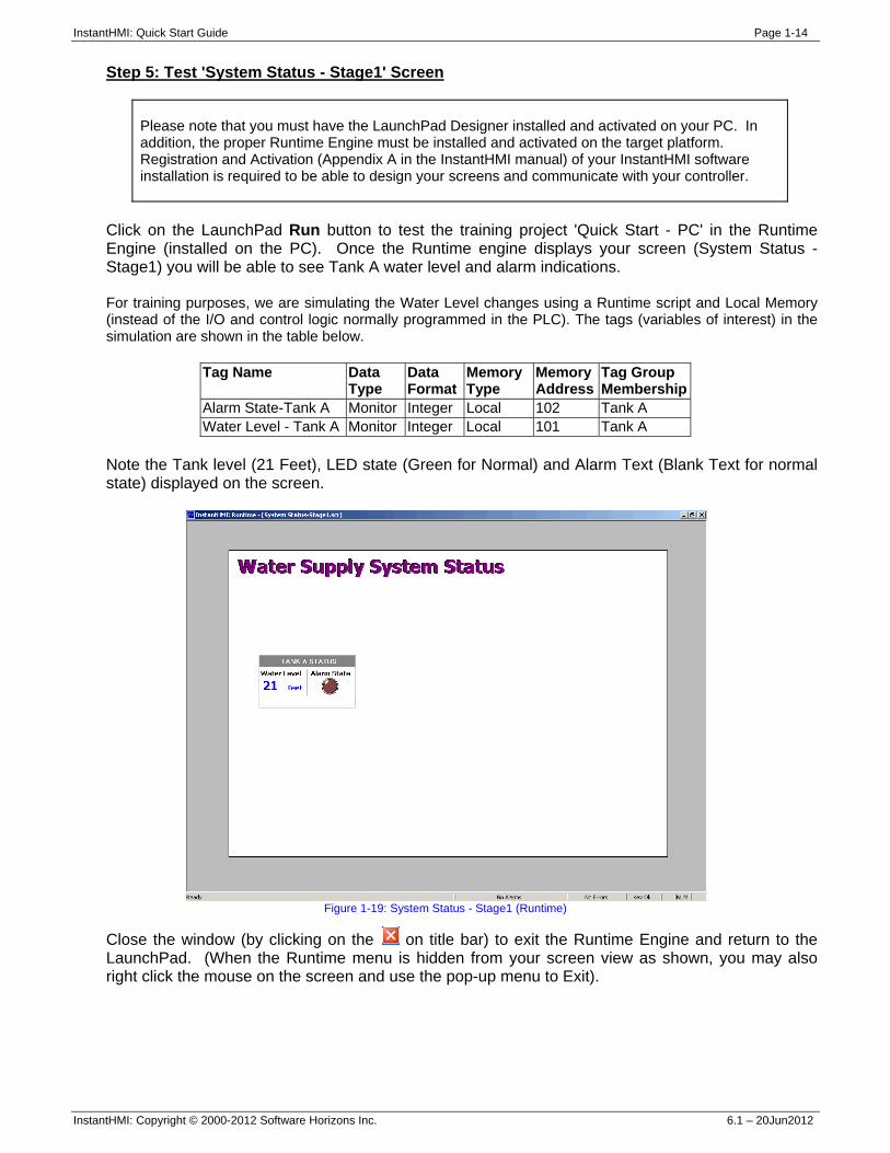
Step 5: Test 'System Status - Stage1' Screen
Please note that you must have the LaunchPad Designer installed and activated on your PC. In addition, the proper Runtime Engine must be installed and activated on the target platform. Registration and Activation (Appendix A in the InstantHMI manual) of your InstantHMI software installation is required to be able to design your screens and communicate with your controller.
Click on the LaunchPad Run button to test the training project 'Quick Start - PC' in the Runtime Engine (installed on the PC). Once the Runtime engine displays your screen (System Status - Stage1) you will be able to see Tank A water level and alarm indications. For training purposes, we are simulating the Water Level changes using a Runtime script and Local Memory (instead of the I/O and control logic normally programmed in the PLC). The tags (variables of interest) in the simulation are shown in the table below.
Tag Name Data Type
Data Format
Memory Type
Memory Address
Tag Group Membership
Alarm State-Tank A Monitor Integer Local 102 Tank A Water Level - Tank A Monitor Integer Local 101 Tank A
Note the Tank level (21 Feet), LED state (Green for Normal) and Alarm Text (Blank Text for normal state) displayed on the screen.
Figure 1-19: System Status - Stage1 (Runtime)
Close the window (by clicking on the on title bar) to exit the Runtime Engine and return to the LaunchPad. (When the Runtime menu is hidden from your screen view as shown, you may also right click the mouse on the screen and use the pop-up menu to Exit).
InstantHMI: Quick Start Guide Page 1-15
InstantHMI: Copyright © 2000-2012 Software Horizons Inc. 6.1 – 20Jun2012
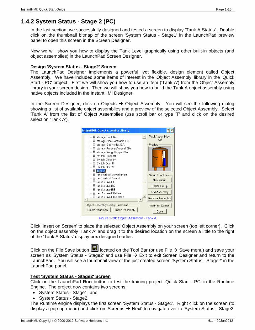
1.4.2 System Status - Stage 2 (PC) In the last section, we successfully designed and tested a screen to display 'Tank A Status'. Double click on the thumbnail bitmap of the screen 'System Status - Stage1' in the LaunchPad preview panel to open this screen in the Screen Designer. Now we will show you how to display the Tank Level graphically using other built-in objects (and object assemblies) in the LaunchPad Screen Designer. Design 'System Status - Stage2' Screen The LaunchPad Designer implements a powerful, yet flexible, design element called Object Assembly. We have included some items of interest in the 'Object Assembly' library in the 'Quick Start - PC' project. First we will show you how to use an item ('Tank A') from the Object Assembly library in your screen design. Then we will show you how to build the Tank A object assembly using native objects included in the InstantHMI Designer. In the Screen Designer, click on Objects Object Assembly. You will see the following dialog showing a list of available object assemblies and a preview of the selected Object Assembly. Select 'Tank A' from the list of Object Assemblies (use scroll bar or type 'T' and click on the desired selection 'Tank A').
Figure 1-20: Object Assembly - Tank A
Click 'Insert on Screen' to place the selected Object Assembly on your screen (top left corner). Click on the object assembly 'Tank A' and drag it to the desired location on the screen a little to the right of the 'Tank A Status' display box designed earlier.
Click on the File Save button located on the Tool Bar (or use File Save menu) and save your screen as 'System Status - Stage2' and use File Exit to exit Screen Designer and return to the LaunchPad. You will see a thumbnail view of the just created screen 'System Status - Stage2' in the LaunchPad panel. Test 'System Status - Stage2' Screen Click on the LaunchPad Run button to test the training project 'Quick Start - PC' in the Runtime Engine. The project now contains two screens: • System Status - Stage1, and • System Status - Stage2.
The Runtime engine displays the first screen 'System Status - Stage1'. Right click on the screen (to display a pop-up menu) and click on 'Screens Next' to navigate over to 'System Status - Stage2'
InstantHMI: Quick Start Guide Page 1-16
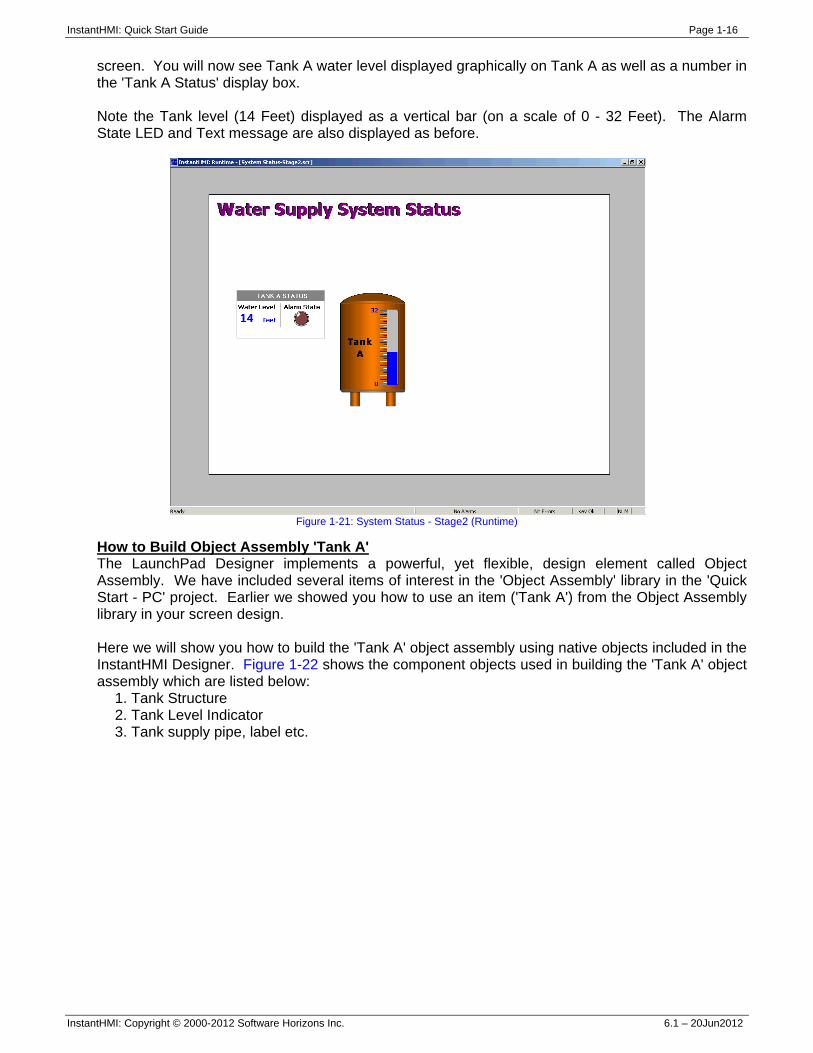
InstantHMI: Copyright © 2000-2012 Software Horizons Inc. 6.1 – 20Jun2012
screen. You will now see Tank A water level displayed graphically on Tank A as well as a number in the 'Tank A Status' display box. Note the Tank level (14 Feet) displayed as a vertical bar (on a scale of 0 - 32 Feet). The Alarm State LED and Text message are also displayed as before.
Figure 1-21: System Status - Stage2 (Runtime)
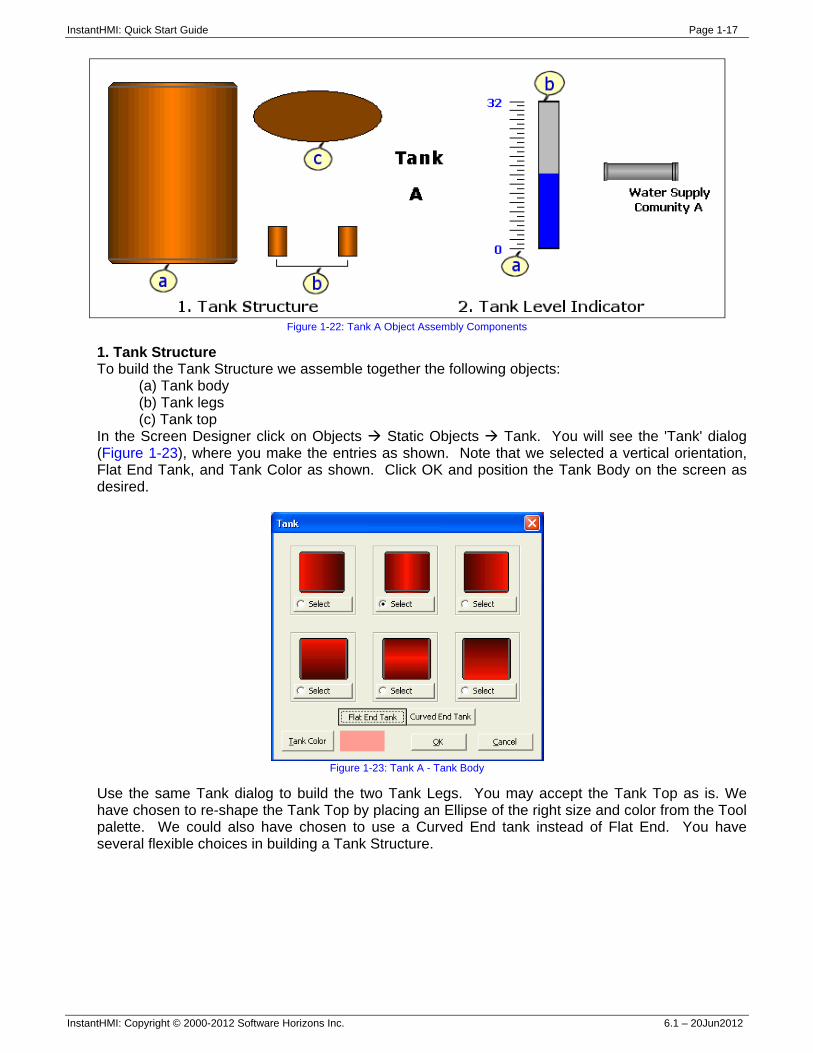
How to Build Object Assembly 'Tank A' The LaunchPad Designer implements a powerful, yet flexible, design element called Object Assembly. We have included several items of interest in the 'Object Assembly' library in the 'Quick Start - PC' project. Earlier we showed you how to use an item ('Tank A') from the Object Assembly library in your screen design. Here we will show you how to build the 'Tank A' object assembly using native objects included in the InstantHMI Designer. Figure 1-22 shows the component objects used in building the 'Tank A' object assembly which are listed below:
1. Tank Structure 2. Tank Level Indicator 3. Tank supply pipe, label etc.
InstantHMI: Quick Start Guide Page 1-17
InstantHMI: Copyright © 2000-2012 Software Horizons Inc. 6.1 – 20Jun2012
Figure 1-22: Tank A Object Assembly Components
1. Tank Structure To build the Tank Structure we assemble together the following objects:
(a) Tank body (b) Tank legs (c) Tank top
In the Screen Designer click on Objects Static Objects Tank. You will see the 'Tank' dialog (Figure 1-23), where you make the entries as shown. Note that we selected a vertical orientation, Flat End Tank, and Tank Color as shown. Click OK and position the Tank Body on the screen as desired.
Figure 1-23: Tank A - Tank Body
Use the same Tank dialog to build the two Tank Legs. You may accept the Tank Top as is. We have chosen to re-shape the Tank Top by placing an Ellipse of the right size and color from the Tool palette. We could also have chosen to use a Curved End tank instead of Flat End. You have several flexible choices in building a Tank Structure.
InstantHMI: Quick Start Guide Page 1-18
InstantHMI: Copyright © 2000-2012 Software Horizons Inc. 6.1 – 20Jun2012
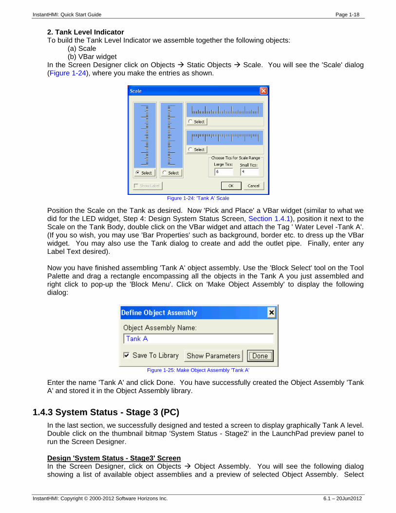
2. Tank Level Indicator To build the Tank Level Indicator we assemble together the following objects:
(a) Scale (b) VBar widget
In the Screen Designer click on Objects Static Objects Scale. You will see the 'Scale' dialog (Figure 1-24), where you make the entries as shown.
Figure 1-24: 'Tank A' Scale
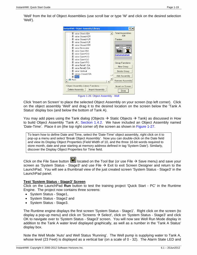
Position the Scale on the Tank as desired. Now 'Pick and Place' a VBar widget (similar to what we did for the LED widget, Step 4: Design System Status Screen, Section 1.4.1), position it next to the Scale on the Tank Body, double click on the VBar widget and attach the Tag ' Water Level -Tank A'. (If you so wish, you may use 'Bar Properties' such as background, border etc. to dress up the VBar widget. You may also use the Tank dialog to create and add the outlet pipe. Finally, enter any Label Text desired). Now you have finished assembling 'Tank A' object assembly. Use the 'Block Select' tool on the Tool Palette and drag a rectangle encompassing all the objects in the Tank A you just assembled and right click to pop-up the 'Block Menu'. Click on 'Make Object Assembly' to display the following dialog:
Figure 1-25: Make Object Assembly 'Tank A'
Enter the name 'Tank A' and click Done. You have successfully created the Object Assembly 'Tank A' and stored it in the Object Assembly library.
1.4.3 System Status - Stage 3 (PC) In the last section, we successfully designed and tested a screen to display graphically Tank A level. Double click on the thumbnail bitmap 'System Status - Stage2' in the LaunchPad preview panel to run the Screen Designer. Design 'System Status - Stage3' Screen In the Screen Designer, click on Objects Object Assembly. You will see the following dialog showing a list of available object assemblies and a preview of selected Object Assembly. Select
InstantHMI: Quick Start Guide Page 1-19
InstantHMI: Copyright © 2000-2012 Software Horizons Inc. 6.1 – 20Jun2012
'Well' from the list of Object Assemblies (use scroll bar or type 'W' and click on the desired selection 'Well').
Figure 1-26: Object Assembly - Well
Click 'Insert on Screen' to place the selected Object Assembly on your screen (top left corner). Click on the object assembly 'Well' and drag it to the desired location on the screen below the 'Tank A Status' display box (and below the bottom of Tank A). You may add pipes using the Tank dialog (Objects Static Objects Tank) as discussed in How to build Object Assembly 'Tank A', Section 1.4.2. We have included an Object Assembly named 'Date-Time'. Place it on (the top right corner of) the screen as shown in Figure 1-27.
To learn how to define Date and Time, select the 'Date-Time' object assembly, right click on it to pop-up a menu and select 'Break Object Assembly'. Now you can double-click on the Date field and view its Display Object Properties (Field Width of 10, and the three 16-bit words required to store month, date and year starting at memory address defined in tag 'System Date'). Similarly, discover the Display Object Properties for Time field.
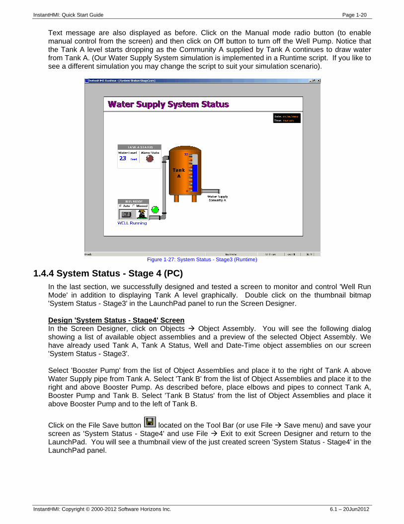
Click on the File Save button located on the Tool Bar (or use File Save menu) and save your screen as 'System Status - Stage3' and use File Exit to exit Screen Designer and return to the LaunchPad. You will see a thumbnail view of the just created screen 'System Status - Stage3' in the LaunchPad panel. Test 'System Status - Stage3' Screen Click on the LaunchPad Run button to test the training project 'Quick Start - PC' in the Runtime Engine. The project now contains three screens: • System Status - Stage1, • System Status - Stage2 and • System Status - Stage3.
The Runtime engine displays the first screen 'System Status - Stage1'. Right click on the screen (to display a pop-up menu) and click on 'Screens Select', click on 'System Status - Stage3' and click OK to navigate over to 'System Status - Stage3' screen. You will now see Well Run Mode display in addition to the Tank A water level displayed graphically, as well as a number in the 'Tank A Status' display box. Note the Well Mode 'Auto' and Well Status 'Running'. The Well pump is supplying water to Tank A, whose level (23 Feet) is displayed as a vertical bar (on a scale of 0 - 32). The Alarm State LED and
InstantHMI: Quick Start Guide Page 1-20
InstantHMI: Copyright © 2000-2012 Software Horizons Inc. 6.1 – 20Jun2012
Text message are also displayed as before. Click on the Manual mode radio button (to enable manual control from the screen) and then click on Off button to turn off the Well Pump. Notice that the Tank A level starts dropping as the Community A supplied by Tank A continues to draw water from Tank A. (Our Water Supply System simulation is implemented in a Runtime script. If you like to see a different simulation you may change the script to suit your simulation scenario).
Figure 1-27: System Status - Stage3 (Runtime)
1.4.4 System Status - Stage 4 (PC) In the last section, we successfully designed and tested a screen to monitor and control 'Well Run Mode' in addition to displaying Tank A level graphically. Double click on the thumbnail bitmap 'System Status - Stage3' in the LaunchPad panel to run the Screen Designer. Design 'System Status - Stage4' Screen In the Screen Designer, click on Objects Object Assembly. You will see the following dialog showing a list of available object assemblies and a preview of the selected Object Assembly. We have already used Tank A, Tank A Status, Well and Date-Time object assemblies on our screen 'System Status - Stage3'. Select 'Booster Pump' from the list of Object Assemblies and place it to the right of Tank A above Water Supply pipe from Tank A. Select 'Tank B' from the list of Object Assemblies and place it to the right and above Booster Pump. As described before, place elbows and pipes to connect Tank A, Booster Pump and Tank B. Select 'Tank B Status' from the list of Object Assemblies and place it above Booster Pump and to the left of Tank B.
Click on the File Save button located on the Tool Bar (or use File Save menu) and save your screen as 'System Status - Stage4' and use File Exit to exit Screen Designer and return to the LaunchPad. You will see a thumbnail view of the just created screen 'System Status - Stage4' in the LaunchPad panel.
InstantHMI: Quick Start Guide Page 1-21
InstantHMI: Copyright © 2000-2012 Software Horizons Inc. 6.1 – 20Jun2012
Test 'System Status - Stage4' Screen Click on the LaunchPad Run button to test the training project 'Quick Start - PC' in the Runtime Engine. The project now contains four screens: • System Status - Stage1, • System Status - Stage2, • System Status - Stage3 and • System Status - Stage4.
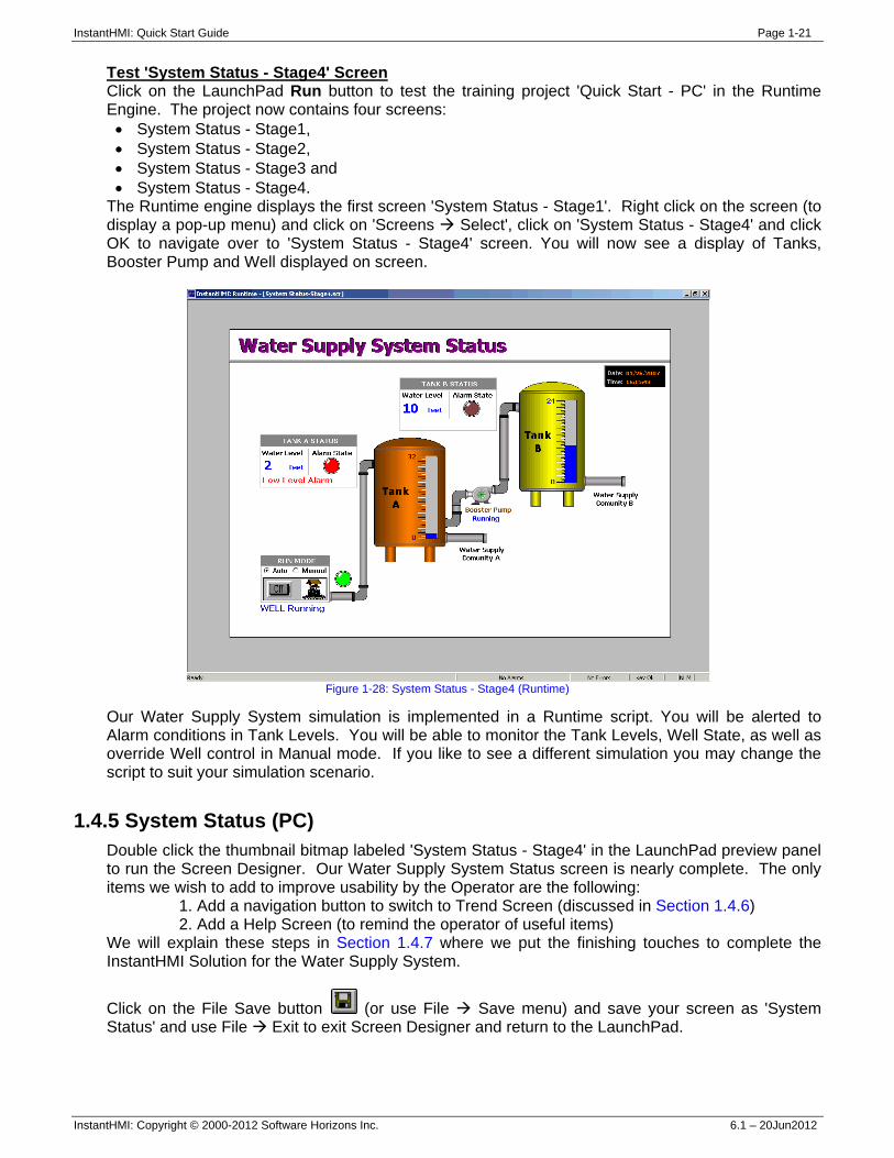
The Runtime engine displays the first screen 'System Status - Stage1'. Right click on the screen (to display a pop-up menu) and click on 'Screens Select', click on 'System Status - Stage4' and click OK to navigate over to 'System Status - Stage4' screen. You will now see a display of Tanks, Booster Pump and Well displayed on screen.
Figure 1-28: System Status - Stage4 (Runtime)
Our Water Supply System simulation is implemented in a Runtime script. You will be alerted to Alarm conditions in Tank Levels. You will be able to monitor the Tank Levels, Well State, as well as override Well control in Manual mode. If you like to see a different simulation you may change the script to suit your simulation scenario.
1.4.5 System Status (PC) Double click the thumbnail bitmap labeled 'System Status - Stage4' in the LaunchPad preview panel to run the Screen Designer. Our Water Supply System Status screen is nearly complete. The only items we wish to add to improve usability by the Operator are the following:
1. Add a navigation button to switch to Trend Screen (discussed in Section 1.4.6) 2. Add a Help Screen (to remind the operator of useful items)
We will explain these steps in Section 1.4.7 where we put the finishing touches to complete the InstantHMI Solution for the Water Supply System.
Click on the File Save button (or use File Save menu) and save your screen as 'System Status' and use File Exit to exit Screen Designer and return to the LaunchPad.
InstantHMI: Quick Start Guide Page 1-22
InstantHMI: Copyright © 2000-2012 Software Horizons Inc. 6.1 – 20Jun2012
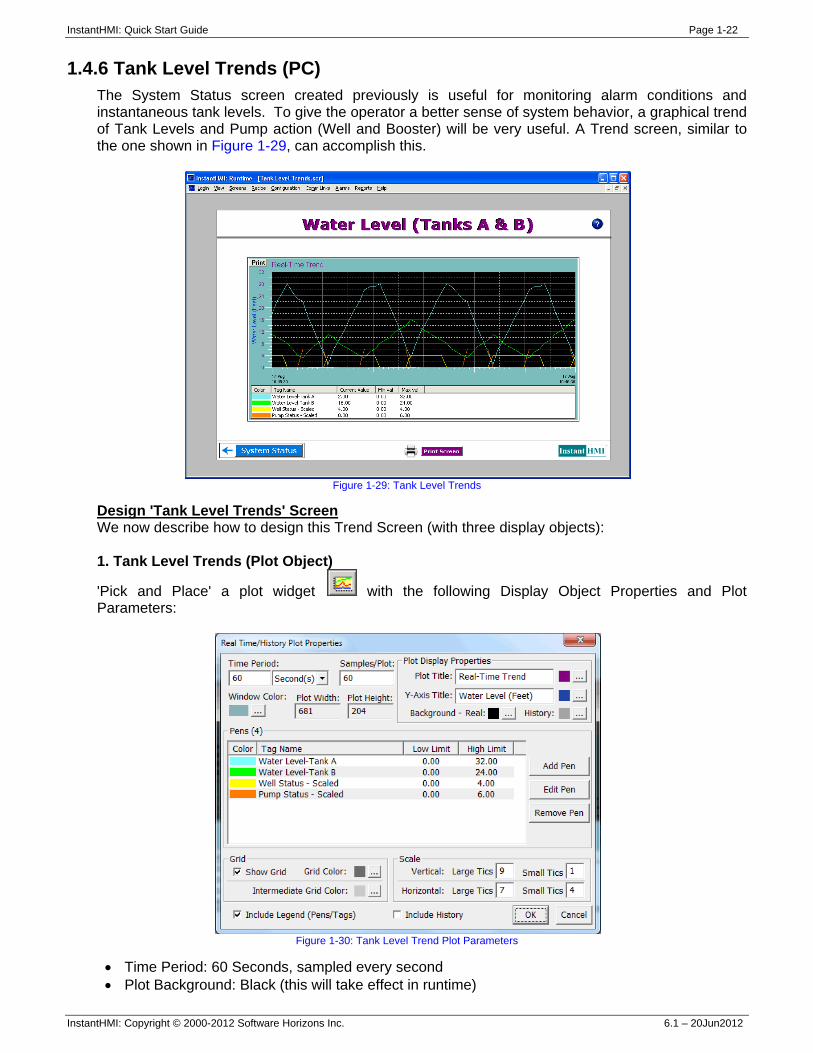
1.4.6 Tank Level Trends (PC) The System Status screen created previously is useful for monitoring alarm conditions and instantaneous tank levels. To give the operator a better sense of system behavior, a graphical trend of Tank Levels and Pump action (Well and Booster) will be very useful. A Trend screen, similar to the one shown in Figure 1-29, can accomplish this.
Figure 1-29: Tank Level Trends
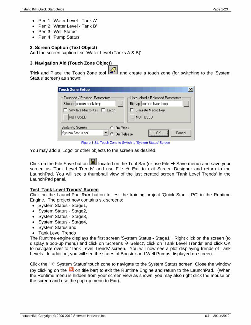
Design 'Tank Level Trends' Screen We now describe how to design this Trend Screen (with three display objects): 1. Tank Level Trends (Plot Object)
'Pick and Place' a plot widget with the following Display Object Properties and Plot Parameters:
Figure 1-30: Tank Level Trend Plot Parameters
• Time Period: 60 Seconds, sampled every second • Plot Background: Black (this will take effect in runtime)
InstantHMI: Quick Start Guide Page 1-23
InstantHMI: Copyright © 2000-2012 Software Horizons Inc. 6.1 – 20Jun2012
• Pen 1: 'Water Level - Tank A' • Pen 2: 'Water Level - Tank B' • Pen 3: 'Well Status' • Pen 4: 'Pump Status'
2. Screen Caption (Text Object) Add the screen caption text 'Water Level (Tanks A & B)'. 3. Navigation Aid (Touch Zone Object)
'Pick and Place' the Touch Zone tool and create a touch zone (for switching to the 'System Status' screen) as shown:
Figure 1-31: Touch Zone to Switch to 'System Status' Screen
You may add a 'Logo' or other objects to the screen as desired.
Click on the File Save button located on the Tool Bar (or use File Save menu) and save your screen as 'Tank Level Trends' and use File Exit to exit Screen Designer and return to the LaunchPad. You will see a thumbnail view of the just created screen 'Tank Level Trends' in the LaunchPad panel. Test 'Tank Level Trends' Screen Click on the LaunchPad Run button to test the training project 'Quick Start - PC' in the Runtime Engine. The project now contains six screens: • System Status - Stage1, • System Status - Stage2, • System Status - Stage3, • System Status - Stage4, • System Status and • Tank Level Trends
The Runtime engine displays the first screen 'System Status - Stage1'. Right click on the screen (to display a pop-up menu) and click on 'Screens Select', click on 'Tank Level Trends' and click OK to navigate over to 'Tank Level Trends' screen. You will now see a plot displaying trends of Tank Levels. In addition, you will see the states of Booster and Well Pumps displayed on screen. Click the ' System Status' touch zone to navigate to the System Status screen. Close the window (by clicking on the on title bar) to exit the Runtime Engine and return to the LaunchPad. (When the Runtime menu is hidden from your screen view as shown, you may also right click the mouse on the screen and use the pop-up menu to Exit).
InstantHMI: Quick Start Guide Page 1-24
InstantHMI: Copyright © 2000-2012 Software Horizons Inc. 6.1 – 20Jun2012
1.4.7 Water Supply System Solution - PC Runtime Platform Our sample application (Fresh Water Supply System) can be adequately presented to the operator using two screens: System Status Screen This screen (as designed in Sections 1.4.1 - 1.4.5) will display Tank Levels, Alarm States, etc. and allow for operator override of the automated requests for Pump actions. Tank Level Trends Screen This screen (as designed in Section 1.4.6) will show the real time trend of the tank water levels and the Pump action. To complete the project design we do the following:
1. Setup project with only the two finished screens 2. Add Screen Navigation Aid on 'System Status' screen 3. Add Print button to save a runtime snapshot of the screen 4. Add Help Screens
Many other enhancements such as Reports, Datalogging, etc. are possible, but are not described here. Note: We have provided the finished project in your InstantHMI installation as 'Quick Start-PC/Backup-Finished'. We have also provided a backup of the project you started with in 'Quick Start-PC/Backup-Start' in case you wish to restore your project for re-training from the starting point. If you wish to skip the steps in the rest of this section you may do so and copy all files from 'Quick Start-PC/Backup-Finished' to 'Quick Start - PC' to check out the finished project. We recommend that at a minimum you review the rest of this section.
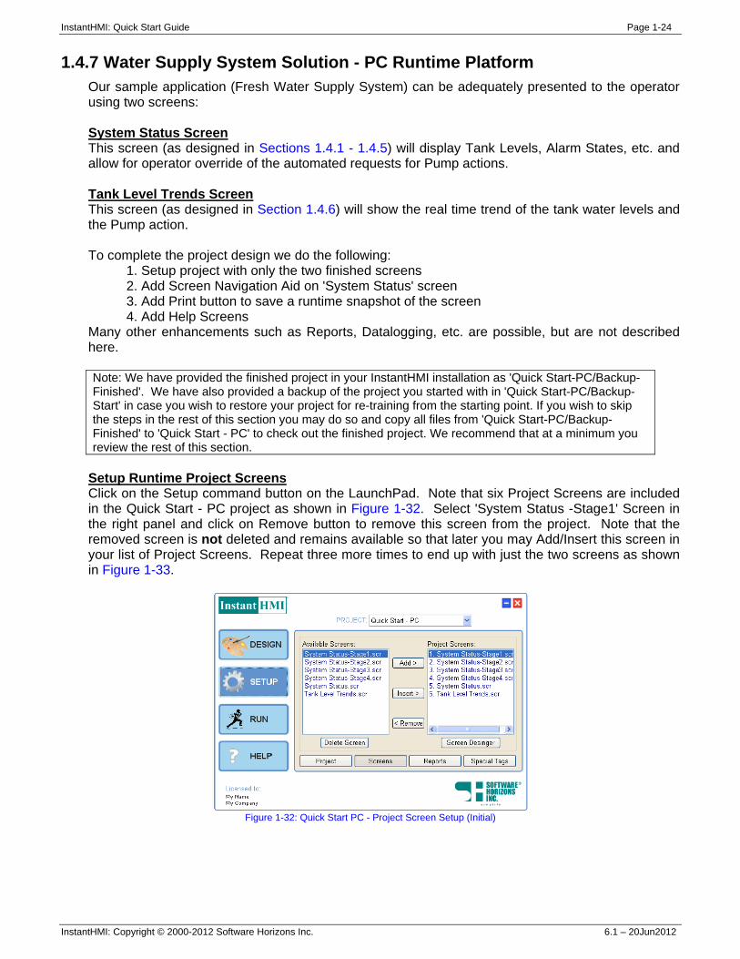
Setup Runtime Project Screens Click on the Setup command button on the LaunchPad. Note that six Project Screens are included in the Quick Start - PC project as shown in Figure 1-32. Select 'System Status -Stage1' Screen in the right panel and click on Remove button to remove this screen from the project. Note that the removed screen is not deleted and remains available so that later you may Add/Insert this screen in your list of Project Screens. Repeat three more times to end up with just the two screens as shown in Figure 1-33.
Figure 1-32: Quick Start PC - Project Screen Setup (Initial)
InstantHMI: Quick Start Guide Page 1-25
InstantHMI: Copyright © 2000-2012 Software Horizons Inc. 6.1 – 20Jun2012
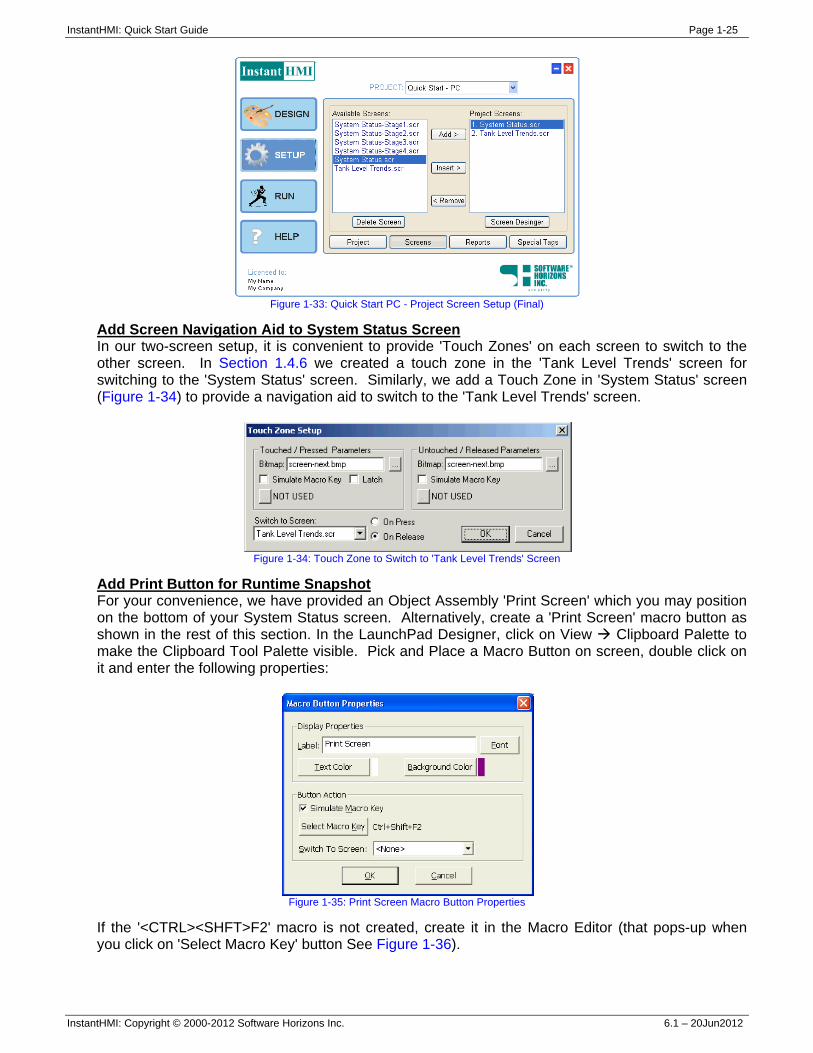
Figure 1-33: Quick Start PC - Project Screen Setup (Final)
Add Screen Navigation Aid to System Status Screen In our two-screen setup, it is convenient to provide 'Touch Zones' on each screen to switch to the other screen. In Section 1.4.6 we created a touch zone in the 'Tank Level Trends' screen for switching to the 'System Status' screen. Similarly, we add a Touch Zone in 'System Status' screen (Figure 1-34) to provide a navigation aid to switch to the 'Tank Level Trends' screen.
Figure 1-34: Touch Zone to Switch to 'Tank Level Trends' Screen
Add Print Button for Runtime Snapshot For your convenience, we have provided an Object Assembly 'Print Screen' which you may position on the bottom of your System Status screen. Alternatively, create a 'Print Screen' macro button as shown in the rest of this section. In the LaunchPad Designer, click on View Clipboard Palette to make the Clipboard Tool Palette visible. Pick and Place a Macro Button on screen, double click on it and enter the following properties:
Figure 1-35: Print Screen Macro Button Properties
If the '<CTRL><SHFT>F2' macro is not created, create it in the Macro Editor (that pops-up when you click on 'Select Macro Key' button See Figure 1-36).
InstantHMI: Quick Start Guide Page 1-26
InstantHMI: Copyright © 2000-2012 Software Horizons Inc. 6.1 – 20Jun2012
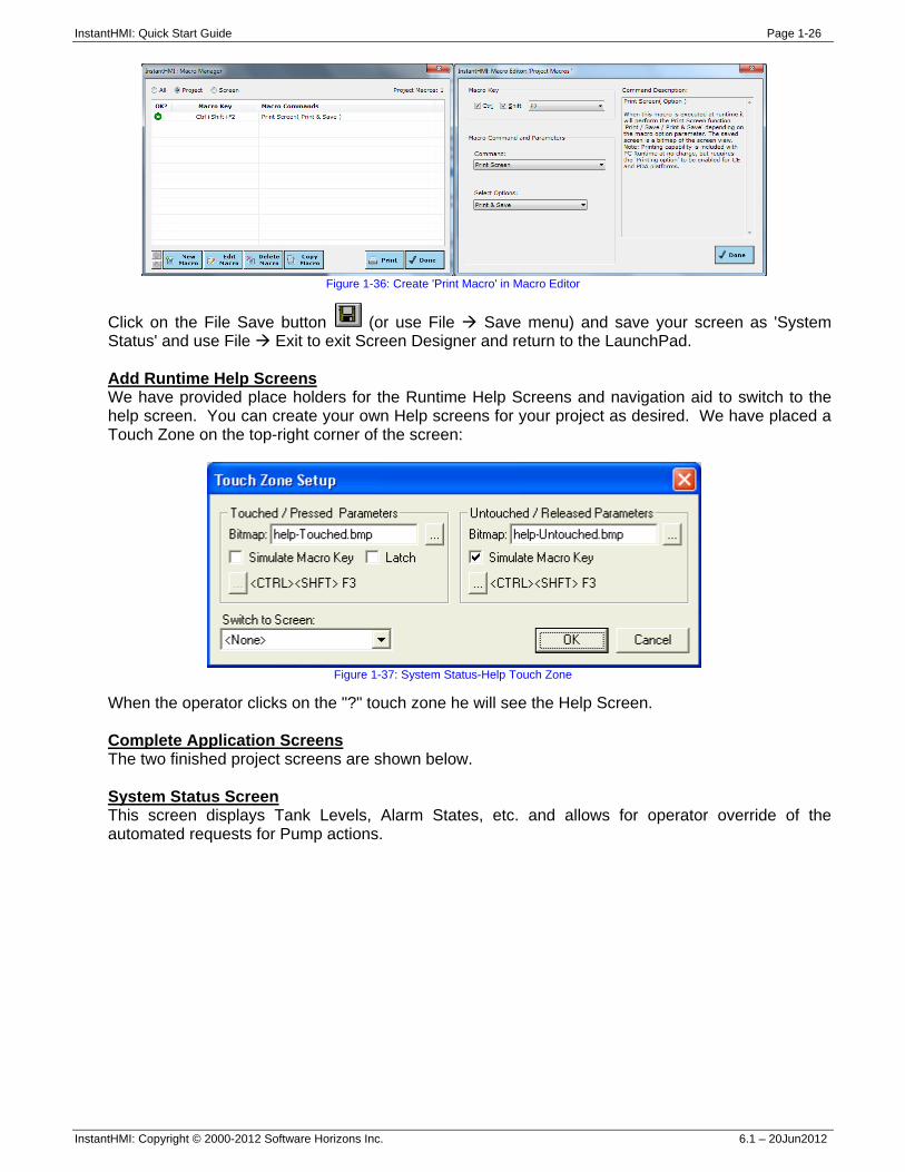
Figure 1-36: Create 'Print Macro' in Macro Editor
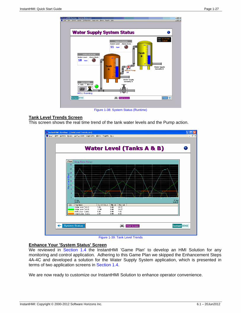
Click on the File Save button (or use File Save menu) and save your screen as 'System Status' and use File Exit to exit Screen Designer and return to the LaunchPad. Add Runtime Help Screens We have provided place holders for the Runtime Help Screens and navigation aid to switch to the help screen. You can create your own Help screens for your project as desired. We have placed a Touch Zone on the top-right corner of the screen:
Figure 1-37: System Status-Help Touch Zone
When the operator clicks on the "?" touch zone he will see the Help Screen. Complete Application Screens The two finished project screens are shown below. System Status Screen This screen displays Tank Levels, Alarm States, etc. and allows for operator override of the automated requests for Pump actions.
InstantHMI: Quick Start Guide Page 1-27
InstantHMI: Copyright © 2000-2012 Software Horizons Inc. 6.1 – 20Jun2012
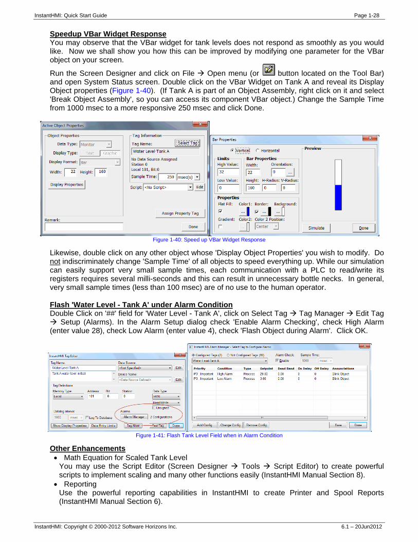
Figure 1-38: System Status (Runtime)
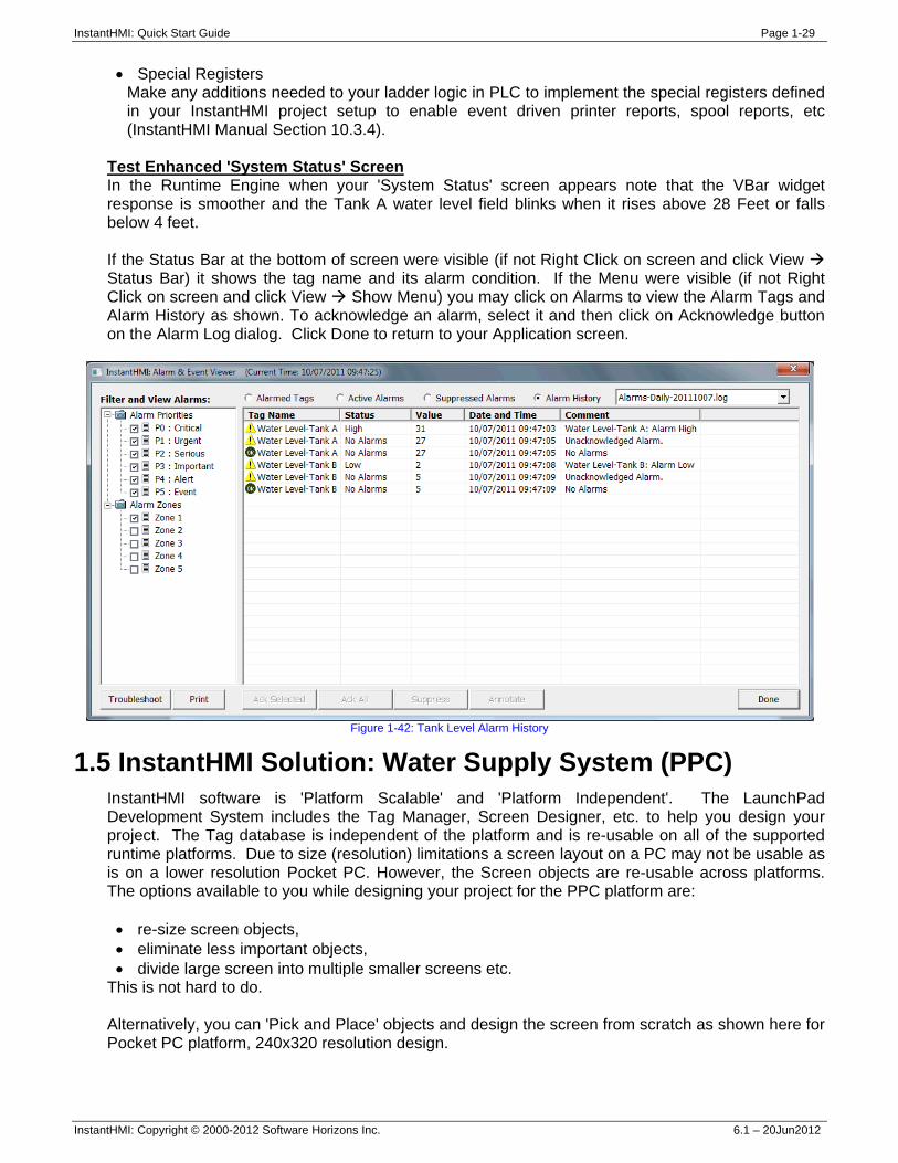
Tank Level Trends Screen This screen shows the real time trend of the tank water levels and the Pump action.
Figure 1-39: Tank Level Trends
Enhance Your 'System Status' Screen We reviewed in Section 1.4 the InstantHMI 'Game Plan' to develop an HMI Solution for any monitoring and control application. Adhering to this Game Plan we skipped the Enhancement Steps 4A-4C and developed a solution for the Water Supply System application, which is presented in terms of two application screens in Section 1.4. We are now ready to customize our InstantHMI Solution to enhance operator convenience.
InstantHMI: Quick Start Guide Page 1-28
InstantHMI: Copyright © 2000-2012 Software Horizons Inc. 6.1 – 20Jun2012
Speedup VBar Widget Response You may observe that the VBar widget for tank levels does not respond as smoothly as you would like. Now we shall show you how this can be improved by modifying one parameter for the VBar object on your screen.
Run the Screen Designer and click on File Open menu (or button located on the Tool Bar) and open System Status screen. Double click on the VBar Widget on Tank A and reveal its Display Object properties (Figure 1-40). (If Tank A is part of an Object Assembly, right click on it and select 'Break Object Assembly', so you can access its component VBar object.) Change the Sample Time from 1000 msec to a more responsive 250 msec and click Done.
Figure 1-40: Speed up VBar Widget Response
Likewise, double click on any other object whose 'Display Object Properties' you wish to modify. Do not indiscriminately change 'Sample Time' of all objects to speed everything up. While our simulation can easily support very small sample times, each communication with a PLC to read/write its registers requires several milli-seconds and this can result in unnecessary bottle necks. In general, very small sample times (less than 100 msec) are of no use to the human operator. Flash 'Water Level - Tank A' under Alarm Condition Double Click on '##' field for 'Water Level - Tank A', click on Select Tag Tag Manager Edit Tag
Setup (Alarms). In the Alarm Setup dialog check 'Enable Alarm Checking', check High Alarm (enter value 28), check Low Alarm (enter value 4), check 'Flash Object during Alarm'. Click OK.
Figure 1-41: Flash Tank Level Field when in Alarm Condition
Other Enhancements • Math Equation for Scaled Tank Level
You may use the Script Editor (Screen Designer Tools Script Editor) to create powerful scripts to implement scaling and many other functions easily (InstantHMI Manual Section 8).
• Reporting Use the powerful reporting capabilities in InstantHMI to create Printer and Spool Reports (InstantHMI Manual Section 6).
InstantHMI: Quick Start Guide Page 1-29
InstantHMI: Copyright © 2000-2012 Software Horizons Inc. 6.1 – 20Jun2012
• Special Registers Make any additions needed to your ladder logic in PLC to implement the special registers defined in your InstantHMI project setup to enable event driven printer reports, spool reports, etc (InstantHMI Manual Section 10.3.4).
Test Enhanced 'System Status' Screen In the Runtime Engine when your 'System Status' screen appears note that the VBar widget response is smoother and the Tank A water level field blinks when it rises above 28 Feet or falls below 4 feet. If the Status Bar at the bottom of screen were visible (if not Right Click on screen and click View Status Bar) it shows the tag name and its alarm condition. If the Menu were visible (if not Right Click on screen and click View Show Menu) you may click on Alarms to view the Alarm Tags and Alarm History as shown. To acknowledge an alarm, select it and then click on Acknowledge button on the Alarm Log dialog. Click Done to return to your Application screen.
Figure 1-42: Tank Level Alarm History
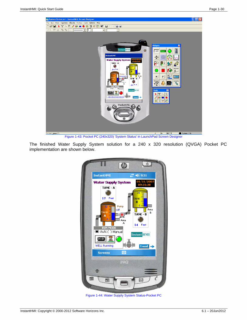
1.5 InstantHMI Solution: Water Supply System (PPC) InstantHMI software is 'Platform Scalable' and 'Platform Independent'. The LaunchPad Development System includes the Tag Manager, Screen Designer, etc. to help you design your project. The Tag database is independent of the platform and is re-usable on all of the supported runtime platforms. Due to size (resolution) limitations a screen layout on a PC may not be usable as is on a lower resolution Pocket PC. However, the Screen objects are re-usable across platforms. The options available to you while designing your project for the PPC platform are: • re-size screen objects, • eliminate less important objects, • divide large screen into multiple smaller screens etc.
This is not hard to do. Alternatively, you can 'Pick and Place' objects and design the screen from scratch as shown here for Pocket PC platform, 240x320 resolution design.
InstantHMI: Quick Start Guide Page 1-30
InstantHMI: Copyright © 2000-2012 Software Horizons Inc. 6.1 – 20Jun2012
Figure 1-43: Pocket PC (240x320) 'System Status' in LaunchPad Screen Designer
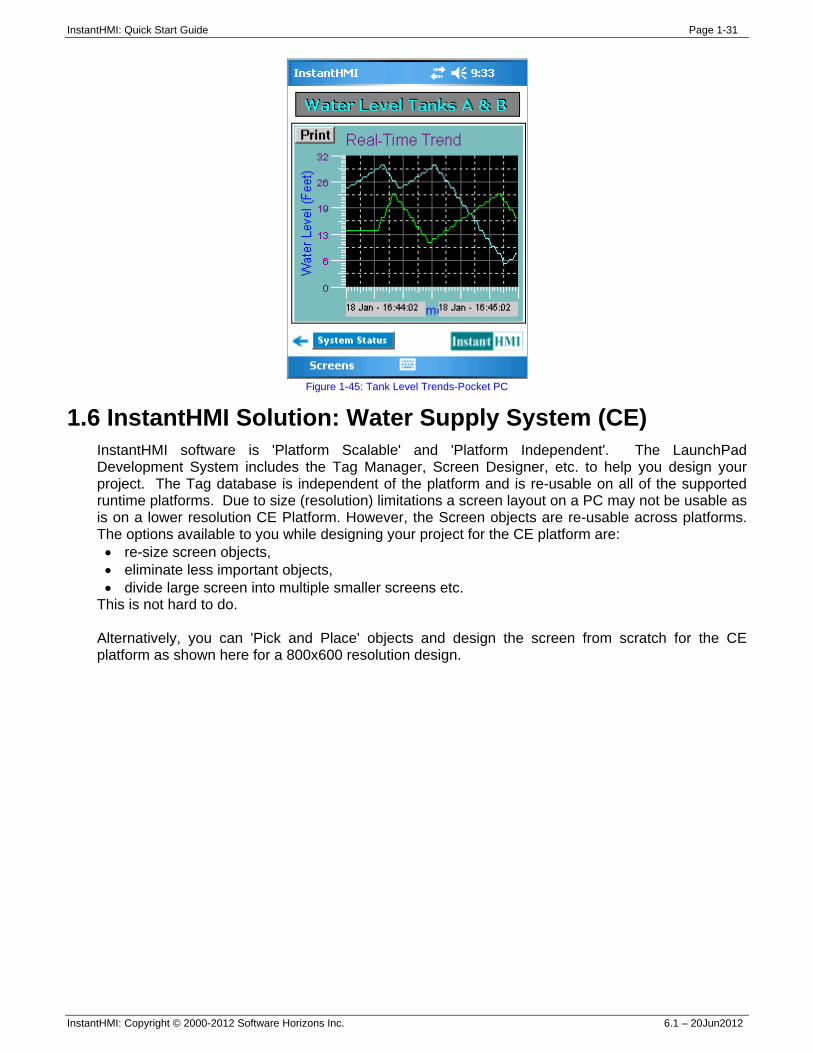
The finished Water Supply System solution for a 240 x 320 resolution (QVGA) Pocket PC implementation are shown below.
Figure 1-44: Water Supply System Status-Pocket PC
InstantHMI: Quick Start Guide Page 1-31
InstantHMI: Copyright © 2000-2012 Software Horizons Inc. 6.1 – 20Jun2012
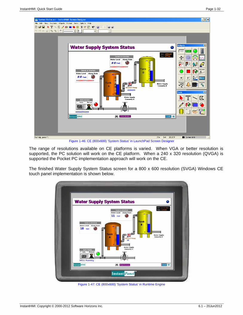
Figure 1-45: Tank Level Trends-Pocket PC
1.6 InstantHMI Solution: Water Supply System (CE) InstantHMI software is 'Platform Scalable' and 'Platform Independent'. The LaunchPad Development System includes the Tag Manager, Screen Designer, etc. to help you design your project. The Tag database is independent of the platform and is re-usable on all of the supported runtime platforms. Due to size (resolution) limitations a screen layout on a PC may not be usable as is on a lower resolution CE Platform. However, the Screen objects are re-usable across platforms. The options available to you while designing your project for the CE platform are: • re-size screen objects, • eliminate less important objects, • divide large screen into multiple smaller screens etc.
This is not hard to do. Alternatively, you can 'Pick and Place' objects and design the screen from scratch for the CE platform as shown here for a 800x600 resolution design.
InstantHMI: Quick Start Guide Page 1-32
InstantHMI: Copyright © 2000-2012 Software Horizons Inc. 6.1 – 20Jun2012
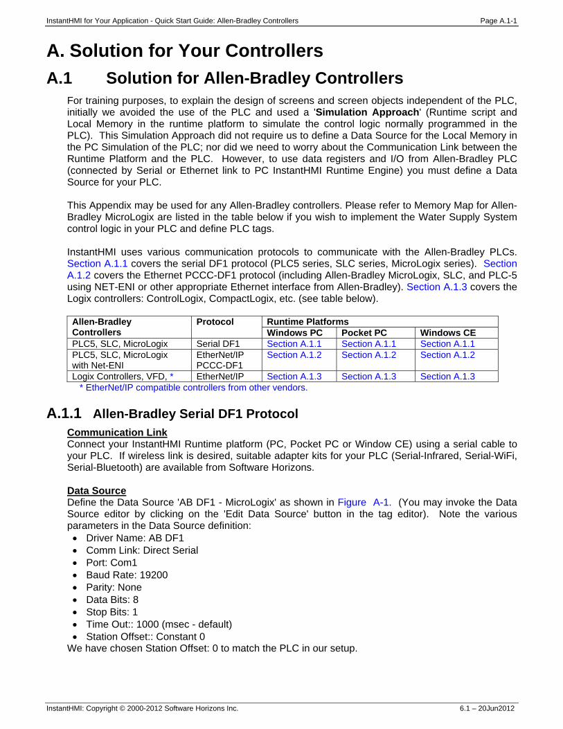
Figure 1-46: CE (800x600) 'System Status' in LaunchPad Screen Designer
The range of resolutions available on CE platforms is varied. When VGA or better resolution is supported, the PC solution will work on the CE platform. When a 240 x 320 resolution (QVGA) is supported the Pocket PC implementation approach will work on the CE. The finished Water Supply System Status screen for a 800 x 600 resolution (SVGA) Windows CE touch panel implementation is shown below.
Figure 1-47: CE (800x600) 'System Status' in Runtime Engine
InstantHMI for Your Application - Quick Start Guide: Allen-Bradley Controllers Page A.1-1
InstantHMI: Copyright © 2000-2012 Software Horizons Inc. 6.1 – 20Jun2012
A. Solution for Your Controllers A.1 Solution for Allen-Bradley Controllers
For training purposes, to explain the design of screens and screen objects independent of the PLC, initially we avoided the use of the PLC and used a 'Simulation Approach' (Runtime script and Local Memory in the runtime platform to simulate the control logic normally programmed in the PLC). This Simulation Approach did not require us to define a Data Source for the Local Memory in the PC Simulation of the PLC; nor did we need to worry about the Communication Link between the Runtime Platform and the PLC. However, to use data registers and I/O from Allen-Bradley PLC (connected by Serial or Ethernet link to PC InstantHMI Runtime Engine) you must define a Data Source for your PLC. This Appendix may be used for any Allen-Bradley controllers. Please refer to Memory Map for Allen-Bradley MicroLogix are listed in the table below if you wish to implement the Water Supply System control logic in your PLC and define PLC tags. InstantHMI uses various communication protocols to communicate with the Allen-Bradley PLCs. Section A.1.1 covers the serial DF1 protocol (PLC5 series, SLC series, MicroLogix series). Section A.1.2 covers the Ethernet PCCC-DF1 protocol (including Allen-Bradley MicroLogix, SLC, and PLC-5 using NET-ENI or other appropriate Ethernet interface from Allen-Bradley). Section A.1.3 covers the Logix controllers: ControlLogix, CompactLogix, etc. (see table below). Allen-Bradley Controllers
Protocol Runtime Platforms Windows PC Pocket PC Windows CE
PLC5, SLC, MicroLogix Serial DF1 Section A.1.1 Section A.1.1 Section A.1.1 PLC5, SLC, MicroLogix with Net-ENI
EtherNet/IP PCCC-DF1
Section A.1.2 Section A.1.2 Section A.1.2
Logix Controllers, VFD, * EtherNet/IP Section A.1.3 Section A.1.3 Section A.1.3 * EtherNet/IP compatible controllers from other vendors.
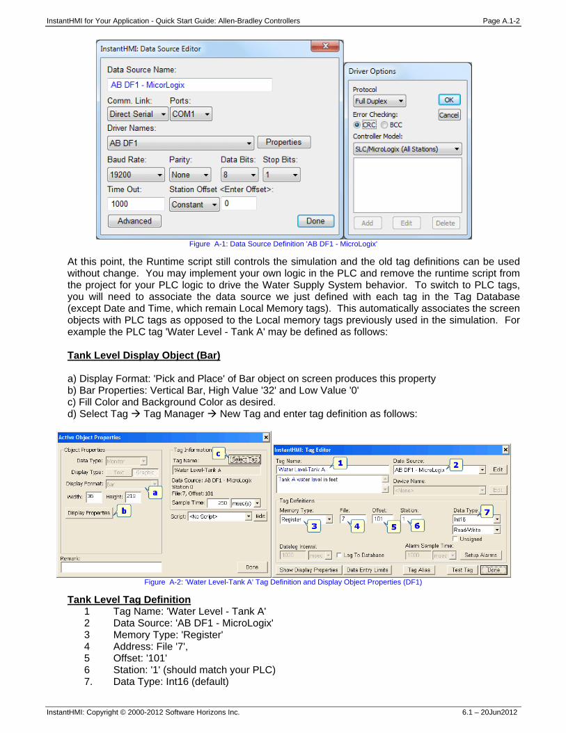
A.1.1 Allen-Bradley Serial DF1 Protocol Communication Link Connect your InstantHMI Runtime platform (PC, Pocket PC or Window CE) using a serial cable to your PLC. If wireless link is desired, suitable adapter kits for your PLC (Serial-Infrared, Serial-WiFi, Serial-Bluetooth) are available from Software Horizons. Data Source Define the Data Source 'AB DF1 - MicroLogix' as shown in Figure A-1. (You may invoke the Data Source editor by clicking on the 'Edit Data Source' button in the tag editor). Note the various parameters in the Data Source definition: • Driver Name: AB DF1 • Comm Link: Direct Serial • Port: Com1 • Baud Rate: 19200 • Parity: None • Data Bits: 8 • Stop Bits: 1 • Time Out:: 1000 (msec - default) • Station Offset:: Constant 0
We have chosen Station Offset: 0 to match the PLC in our setup.
InstantHMI for Your Application - Quick Start Guide: Allen-Bradley Controllers Page A.1-2
InstantHMI: Copyright © 2000-2012 Software Horizons Inc. 6.1 – 20Jun2012
Figure A-1: Data Source Definition 'AB DF1 - MicroLogix'
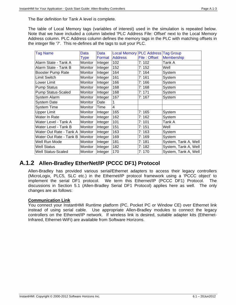
At this point, the Runtime script still controls the simulation and the old tag definitions can be used without change. You may implement your own logic in the PLC and remove the runtime script from the project for your PLC logic to drive the Water Supply System behavior. To switch to PLC tags, you will need to associate the data source we just defined with each tag in the Tag Database (except Date and Time, which remain Local Memory tags). This automatically associates the screen objects with PLC tags as opposed to the Local memory tags previously used in the simulation. For example the PLC tag 'Water Level - Tank A' may be defined as follows: Tank Level Display Object (Bar) a) Display Format: 'Pick and Place' of Bar object on screen produces this property b) Bar Properties: Vertical Bar, High Value '32' and Low Value '0' c) Fill Color and Background Color as desired. d) Select Tag Tag Manager New Tag and enter tag definition as follows:
Figure A-2: 'Water Level-Tank A' Tag Definition and Display Object Properties (DF1)
Tank Level Tag Definition 1 Tag Name: 'Water Level - Tank A' 2 Data Source: 'AB DF1 - MicroLogix' 3 Memory Type: 'Register' 4 Address: File '7', 5 Offset: '101' 6 Station: '1' (should match your PLC) 7. Data Type: Int16 (default)
InstantHMI for Your Application - Quick Start Guide: Allen-Bradley Controllers Page A.1-3
InstantHMI: Copyright © 2000-2012 Software Horizons Inc. 6.1 – 20Jun2012
The Bar definition for Tank A level is complete. The table of Local Memory tags (variables of interest) used in the simulation is repeated below. Note that we have included a column labeled 'PLC Address File: Offset' next to the Local Memory Address column. PLC Address column defines the memory tags in the PLC with matching offsets in the integer file '7'. This re-defines all the tags to suit your PLC.
Tag Name Data Type
Data Format
Local Memory Address
PLC AddressFile : Offset
Tag Group Membership
Alarm State - Tank A Monitor Integer 102 7: 102 Tank A Alarm State - Tank B Monitor Integer 152 7: 152 Well Booster Pump Rate Monitor Integer 164 7: 164 System Limit Switch Monitor Integer 161 7: 161 System Lower Limit Monitor Integer 166 7: 166 System Pump Status Monitor Integer 168 7: 168 System Pump Status-Scaled Monitor Integer 168 7: 171 System System Alarm Monitor Integer 167 7: 167 System System Date Monitor Date 1 System Time Monitor Time 4 Upper Limit Monitor Integer 165 7: 165 System Water In Rate Monitor Integer 162 7: 162 System Water Level - Tank A Monitor Integer 101 7: 101 Tank A Water Level - Tank B Monitor Integer 151 7: 151 Well Water Out Rate - Tank A Monitor Integer 163 7: 163 System Water Out Rate - Tank B Monitor Integer 169 7: 169 System Well Run Mode Monitor Integer 181 7: 181 System, Tank A, WellWell Status Monitor Integer 182 7: 182 System, Tank A, WellWell Status-Scaled Monitor Integer 170 7: 170 System, Tank A, Well
A.1.2 Allen-Bradley EtherNet/IP (PCCC DF1) Protocol
Allen-Bradley has provided various serial/Ethernet adapters to access their legacy controllers (MicroLogix, PLC5, SLC etc.) in the Ethernet/IP protocol framework using a 'PCCC object' to implement the serial DF1 protocol. We term this Ethernet/IP (PCCC DF1) Protocol. The discussions in Section 5.1 (Allen-Bradley Serial DF1 Protocol) applies here as well. The only changes are as follows: Communication Link You connect your InstantHMI Runtime platform (PC, Pocket PC or Window CE) over Ethernet link instead of using serial cable. Use appropriate Allen-Bradley modules to connect the legacy controllers on the Ethernet/IP network. If wireless link is desired, suitable adapter kits (Ethernet-Infrared, Ethernet-WiFi) are available from Software Horizons.
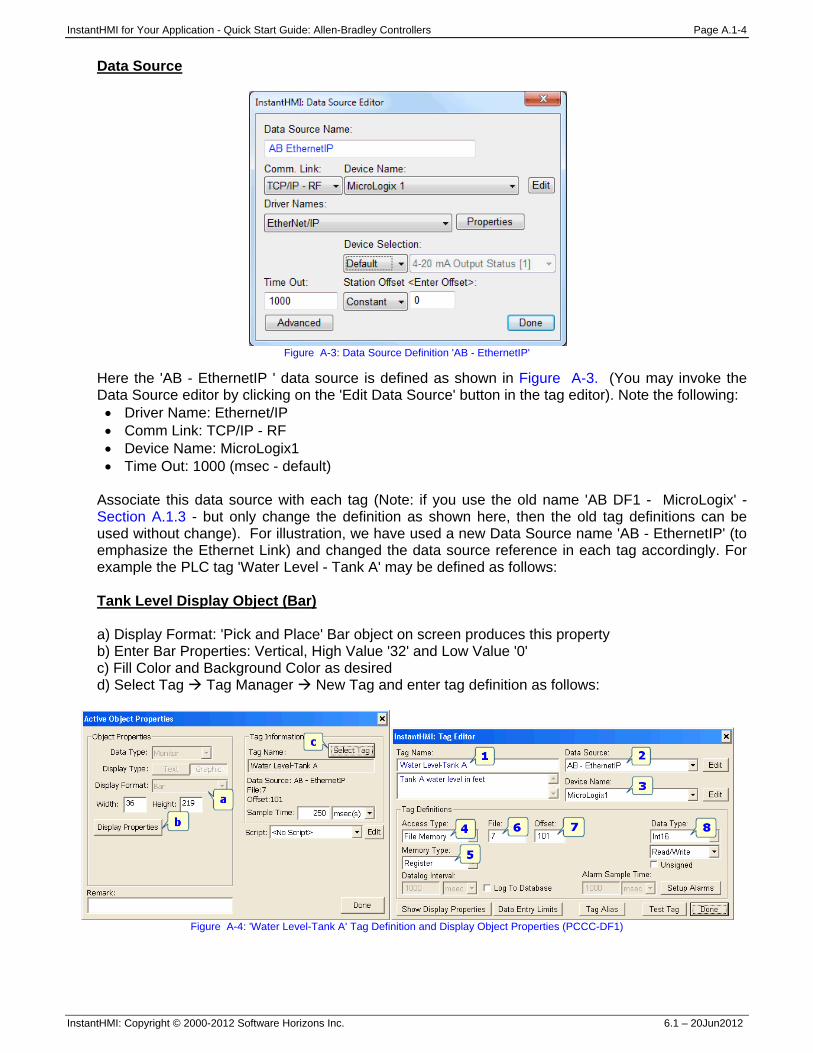
InstantHMI for Your Application - Quick Start Guide: Allen-Bradley Controllers Page A.1-4
InstantHMI: Copyright © 2000-2012 Software Horizons Inc. 6.1 – 20Jun2012
Data Source
Figure A-3: Data Source Definition 'AB - EthernetIP'
Here the 'AB - EthernetIP ' data source is defined as shown in Figure A-3. (You may invoke the Data Source editor by clicking on the 'Edit Data Source' button in the tag editor). Note the following: • Driver Name: Ethernet/IP • Comm Link: TCP/IP - RF • Device Name: MicroLogix1 • Time Out: 1000 (msec - default)
Associate this data source with each tag (Note: if you use the old name 'AB DF1 - MicroLogix' - Section A.1.3 - but only change the definition as shown here, then the old tag definitions can be used without change). For illustration, we have used a new Data Source name 'AB - EthernetIP' (to emphasize the Ethernet Link) and changed the data source reference in each tag accordingly. For example the PLC tag 'Water Level - Tank A' may be defined as follows: Tank Level Display Object (Bar) a) Display Format: 'Pick and Place' Bar object on screen produces this property b) Enter Bar Properties: Vertical, High Value '32' and Low Value '0' c) Fill Color and Background Color as desired d) Select Tag Tag Manager New Tag and enter tag definition as follows:
Figure A-4: 'Water Level-Tank A' Tag Definition and Display Object Properties (PCCC-DF1)

InstantHMI for Your Application - Quick Start Guide: Allen-Bradley Controllers Page A.1-5
InstantHMI: Copyright © 2000-2012 Software Horizons Inc. 6.1 – 20Jun2012
Tank Level Tag Definition 1. Tag Name: 'Water Level - Tank A' 2. Data Source: 'AB - EthernetIP' 3. Access Type: 'File Memory' 4. Memory Type: 'Register' 5. Address: File '7', 6. Address: Offset '101' 7. Device Name: 'MicroLogix1' (should match PLC IP Address etc.) 8. Data Type: Int16 (default)
The Bar definition for Tank A level is complete. A.1.3 Allen-Bradley EtherNet/IP Protocol
Allen-Bradley has provided various Ethernet adapters to access their Logix controllers in the Ethernet/IP protocol framework using Logix Tags. In addition, Allen-Bradley also allows a 'File Mapping' of Logix Tags which enables access to these tags using the legacy 'PCCC Object' approach discussed in Section A.1.2. Communication Link You connect your InstantHMI Runtime platform (PC, Pocket PC or Window CE) over Ethernet link. Use appropriate Allen-Bradley modules to connect the Logix controllers on the Ethernet/IP network. If wireless link is desired, suitable adapter kits (Ethernet-Infrared, Ethernet-WiFi) are available from Software Horizons. Data Source
Figure A-5: Data Source Definition 'ControlLogix'
Here the 'ControlLogix' data source is defined as shown Figure A-4. (You may invoke the Data Source editor by clicking on the 'Edit Data Source' button in the tag editor). Note the following: • Driver Name: EtherNet/IP • Comm Link: TCP/IP - RF • Device Name: ControlLogix-PLC1 • Time Out: 1000 (msec - default)
You define the Data Source 'ControlLogix' as shown and associate this data source with each tag. For illustration, we have used a new Data Source name (to emphasize the Logix controller
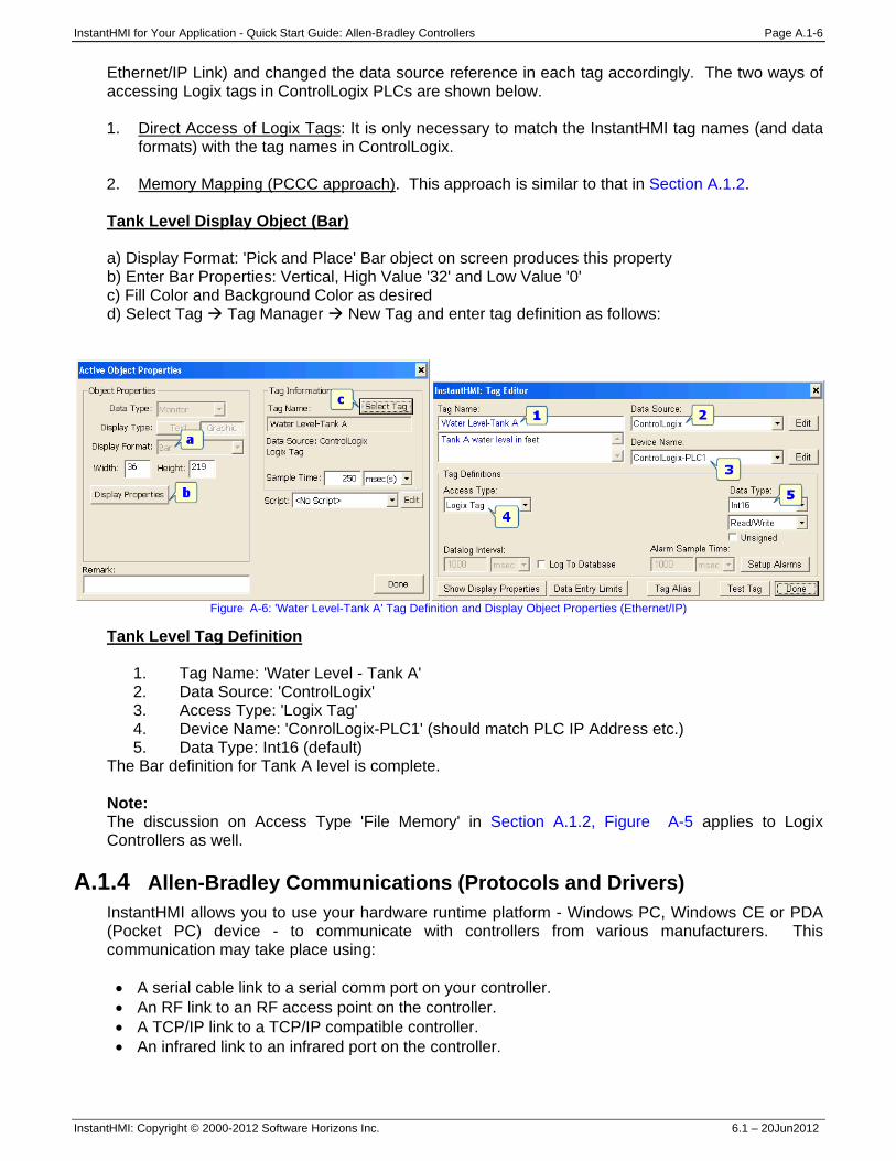
InstantHMI for Your Application - Quick Start Guide: Allen-Bradley Controllers Page A.1-6
InstantHMI: Copyright © 2000-2012 Software Horizons Inc. 6.1 – 20Jun2012
Ethernet/IP Link) and changed the data source reference in each tag accordingly. The two ways of accessing Logix tags in ControlLogix PLCs are shown below. 1. Direct Access of Logix Tags: It is only necessary to match the InstantHMI tag names (and data
formats) with the tag names in ControlLogix. 2. Memory Mapping (PCCC approach). This approach is similar to that in Section A.1.2. Tank Level Display Object (Bar) a) Display Format: 'Pick and Place' Bar object on screen produces this property b) Enter Bar Properties: Vertical, High Value '32' and Low Value '0' c) Fill Color and Background Color as desired d) Select Tag Tag Manager New Tag and enter tag definition as follows:
Figure A-6: 'Water Level-Tank A' Tag Definition and Display Object Properties (Ethernet/IP)
Tank Level Tag Definition 1. Tag Name: 'Water Level - Tank A' 2. Data Source: 'ControlLogix' 3. Access Type: 'Logix Tag' 4. Device Name: 'ConrolLogix-PLC1' (should match PLC IP Address etc.) 5. Data Type: Int16 (default)
The Bar definition for Tank A level is complete. Note: The discussion on Access Type 'File Memory' in Section A.1.2, Figure A-5 applies to Logix Controllers as well.
A.1.4 Allen-Bradley Communications (Protocols and Drivers) InstantHMI allows you to use your hardware runtime platform - Windows PC, Windows CE or PDA (Pocket PC) device - to communicate with controllers from various manufacturers. This communication may take place using: • A serial cable link to a serial comm port on your controller. • An RF link to an RF access point on the controller. • A TCP/IP link to a TCP/IP compatible controller. • An infrared link to an infrared port on the controller.
InstantHMI for Your Application - Quick Start Guide: Allen-Bradley Controllers Page A.1-7
InstantHMI: Copyright © 2000-2012 Software Horizons Inc. 6.1 – 20Jun2012
If your controller does not support Wireless RF communications (WiFi or Bluetooth) you may be able to use the RF-Kit from Software Horizons to convert the serial port on your controller to a Wireless RF connection. Similarly, if your controller does not have a built-in IR port, you may be able to use the IR-Kit from Software Horizons to convert the serial port on your controller to an IR port.
Please note that you must have the proper runtime engine installed on the target platform, and you must Register and Activate (see Appendix A in the InstantHMI manual) your InstantHMI software installation to communicate with your controller.
Serial DF1 Communication Protocol - Driver 33
Note: Driver 33 now includes the functionality of the previous Drivers 33, 34 and driver 34 is retired.
The communication link is used to transfer information between the runtime platform and your controller according to the Allen-Bradley DF1 Protocol. These include MicroLogix, SLC, and Allen-Bradley PLC-5 (using KF2 or other appropriate serial interface from Allen- Bradley). The functions implemented in the standard release of InstantHMI Driver 33 are listed in Addressing Section A.1.4. If you need any additional functions please contact Software Horizons. Setting up your PLC for Proper Communications InstantHMI uses a default setting of 9600 baud, no parity, 8 data bits, 1 stop bit. Use this driver to interface with Allen-Bradley SLC 5/01, 5/02, 5/03, 5/04 (channel 0), MicroLogix Series, or DF1 protocol compatible controllers.
Step 1: Follow detailed installation instructions in the Allen-Bradley users manual to set up your PLC, modules and cabling.
Step 2: Make sure the PLC, modules and cables are installed correctly by testing your
installation using Allen-Bradley Programming software. If you choose a lower/higher baud rate, or different Station Number; make sure the InstantHMI Data Source reflects any changes you make. Please see Section A.1.1 of the InstantHMI Manual for more information on how to configure data sources. Cable Connections Connect the PLC to the RS-232C port of your runtime platform using the appropriate Allen-Bradley cable for the processor you are communicating with. For PLC5, you may also use a null-modem adapter with a straight through cable. Alternatively, you may also use AB 1747-CP3 cable or other appropriate Allen-Bradley cable for the processor you are communicating with. Some PDAs or Windows CE devices may require a converter to communicate with the device (contact Software Horizons for further information).
InstantHMI for Your Application - Quick Start Guide: Allen-Bradley Controllers Page A.1-8
InstantHMI: Copyright © 2000-2012 Software Horizons Inc. 6.1 – 20Jun2012
EtherNet/IP Communication Protocol - Driver 78
Note: Driver 78 now includes the functionality of this Driver 71, which will be retired soon.
The communication link is used to transfer information between the runtime platform and your controller according to the Allen-Bradley EtherNet/IP protocol for Logix Controllers and PCCC-DF1 protocol for legacy controllers. PCCC-DF1 is the EtherNet/IP adaptation of DF1 protocol to support Allen-Bradley legacy controllers (including MicroLogix, SLC, and Allen-Bradley PLC-5 - using NET-ENI or other appropriate Ethernet interface from Allen-Bradley). The functions implemented in the standard release of InstantHMI Driver 78 for PCCC-DF1 are listed in Addressing Section A.1.4. If you need any additional functions please contact Software Horizons. Setting up your PLC for Proper Communications Use this driver to interface with Allen-Bradley EtherNet/IP PCCC-DF1 protocol compatible controllers (including Allen-Bradley MicroLogix, SLC, and PLC-5 - using NET-ENI or other appropriate Ethernet interface from Allen-Bradley). For ControlLogix controllers you may employ a PLC5 style memory mapping of the Logix controller tags or use Access Type 'Logix Tags'.
Step 1: Follow detailed installation instructions in the Allen-Bradley user manuals to set up your PLC, modules, and cabling.
Step 2: Make sure the PLC, modules, and cables are installed correctly by testing your installation using Allen-Bradley Programming software.
Please see Sections A.1.2, A.1.3 for more information on how to configure data sources. Cable Connections Follow detailed installation instructions in the Allen-Bradley user manuals to set up your PLC, modules, and cabling. Some PDAs or Windows CE devices may require an adapter to communicate with the device (contact Software Horizons for further information).
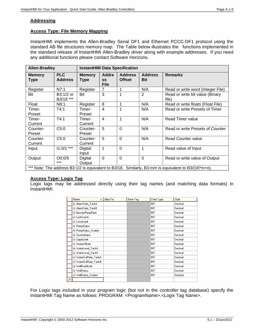
InstantHMI for Your Application - Quick Start Guide: Allen-Bradley Controllers Page A.1-9
InstantHMI: Copyright © 2000-2012 Software Horizons Inc. 6.1 – 20Jun2012
Addressing Access Type: File Memory Mapping InstantHMI implements the Allen-Bradley Serial DF1 and Ethernet PCCC-DF1 protocol using the standard AB file structures memory map. The Table below illustrates the functions implemented in the standard release of InstantHMI Allen-Bradley driver along with example addresses. If you need any additional functions please contact Software Horizons.
Allen-Bradley InstantHMI Data Specification Memory Type
PLC Address
Memory Type
Address File
Address Offset
Address Bit
Remarks
Register N7:1 Register 7 1 N/A Read or write word (Integer File) Bit B3:1/2 or
B3/18 *** Bit 3 1 2 Read or write bit value (Binary
file) Float N8:1 Register 8 1 N/A Read or write floats (Float File) Timer-Preset
T4:1 Timer-Preset
4 1 N/A Read or write Presets of Timer
Timer-Current
T4:1 Timer-Current
4 1 N/A Read Timer value
Counter-Preset
C5:0 Counter-Preset
5 0 N/A Read or write Presets of Counter
Counter-Current
C5:0 Counter-Current
5 0 N/A Read Counter value
Input I1:0/1 *** Digital Input
1 0 1 Read value of Input
Output O0:0/5 ***
Digital Output
0 0 5 Read or write value of Output
*** Note: The address B3:1/2 is equivalent to B3/18. Similarly, B3:m/n is equivalent to B3/(16*m+n). Access Type: Logix Tag Logix tags may be addressed directly using their tag names (and matching data formats) in InstantHMI.
For Logix tags included in your program logic (but not in the controller tag database) specify the InstantHMI Tag Name as follows: PROGRAM: <ProgramName>.<Logix Tag Name>.

InstantHMI for Your Application - Quick Start Guide: Allen-Bradley Controllers Page A.1-10
InstantHMI: Copyright © 2000-2012 Software Horizons Inc. 6.1 – 20Jun2012
Access Type: Object Attributes CIP Classes and Instances supporting the GetAttributeSingle and SetAttributeSingle services can be accessed using the ‘Object Attribute’ Access Type. To create a Tag referencing a Class Attribute select Object Attribute from the Access Type pull down menu, and in the fields below specify the Class ID, Instance ID, and Attribute ID. If the attribute is a Class Attribute then specify the Instance ID as zero. As an example we will create a Tag referencing the ‘Preset Speed 1’ parameter of an AB PowerFlex 70 variable frequency drive using the Parameter Object Class (Class ID 15). In the case of the PowerFlex the parameter number represents the Parameter Object instance containing the parameter data (PowerFlex manuals document the Parameter IDs of each accessible parameter). ‘Preset Speed 1’ is parameter number 101. Parameter Object Instance Attribute 1 contains the data value for the parameter. The tag specification for the ‘Preset Speed 1’ attribute is as follows: Access Type: Object Attribute Class ID: 15 Instance ID: 101 Attribute ID: 1
InstantHMI for Your Application - Quick Start Guide: Modbus Controllers Page A.2-1
InstantHMI: Copyright © 2000-2012 Software Horizons Inc. 6.1 – 20Jun2012
A.2 Solution for Modbus Controllers For training purposes, to explain the design of screens and screen objects independent of the PLC, initially we avoided the use of the PLC and used a 'Simulation Approach' (Runtime script and Local Memory in the runtime platform to simulate the control logic normally programmed in the PLC). This Simulation Approach did not require us to define a Data Source for the Local Memory in the PC Simulation of the PLC; nor did we need to worry about the Communication Link between the Runtime Platform and the PLC. However, to use data registers and I/O from Modbus PLC (connected by Serial or Ethernet link to PC InstantHMI Runtime Engine) you must define a Data Source for your PLC. This Appendix may be used for any Modbus controllers. Please refer to Memory Map for Modbus PLC (Addressing Section A.2.3) if you wish to implement the Water Supply System control logic in your PLC and define PLC tags. InstantHMI uses various communication protocols to communicate with the Modbus PLCs. Section A.2.1 covers the serial ModbusRTU/Ascii protocol. Section A.2.2 covers the Ethernet Modbus -TCP protocol.
A.2.1 Modbus Serial RTU/Ascii Protocol Communication Link Connect your InstantHMI Runtime platform (PC, Pocket PC or Window CE) using a serial cable to your PLC. If wireless link is desired, suitable adapter kits for your PLC (Serial-Infrared, Serial-WiFi, Serial-Bluetooth) are available from Software Horizons. Data Source Define the Data Source 'ModbusRTU' as shown in Figure A-7. (You may invoke the Data Source editor by clicking on the 'Edit Data Source' button in the tag editor). Note the various parameters in the Data Source definition: • Driver Name: Modbus • Comm Link: Direct Serial • Port: Com1 • Baud Rate: 9600 • Parity: None • Data Bits: 8 • Stop Bits: 1 • Time Out: 1000 (msec - default) • Station Offset: 0
We have chosen Station Offset: 0 to match the PLC in our setup. In addition, in the driver properties we have selected Comm Mode to be RTU (as opposed to Ascii). Other driver options may be chosen to suit your own controller.
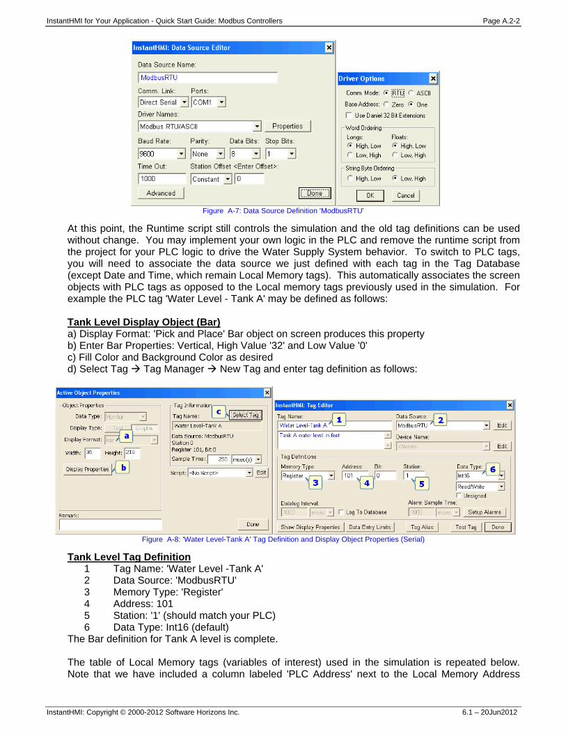
InstantHMI for Your Application - Quick Start Guide: Modbus Controllers Page A.2-2
InstantHMI: Copyright © 2000-2012 Software Horizons Inc. 6.1 – 20Jun2012
Figure A-7: Data Source Definition 'ModbusRTU'
At this point, the Runtime script still controls the simulation and the old tag definitions can be used without change. You may implement your own logic in the PLC and remove the runtime script from the project for your PLC logic to drive the Water Supply System behavior. To switch to PLC tags, you will need to associate the data source we just defined with each tag in the Tag Database (except Date and Time, which remain Local Memory tags). This automatically associates the screen objects with PLC tags as opposed to the Local memory tags previously used in the simulation. For example the PLC tag 'Water Level - Tank A' may be defined as follows: Tank Level Display Object (Bar) a) Display Format: 'Pick and Place' Bar object on screen produces this property b) Enter Bar Properties: Vertical, High Value '32' and Low Value '0' c) Fill Color and Background Color as desired d) Select Tag Tag Manager New Tag and enter tag definition as follows:
Figure A-8: 'Water Level-Tank A' Tag Definition and Display Object Properties (Serial)
Tank Level Tag Definition 1 Tag Name: 'Water Level -Tank A' 2 Data Source: 'ModbusRTU' 3 Memory Type: 'Register' 4 Address: 101 5 Station: '1' (should match your PLC) 6 Data Type: Int16 (default)
The Bar definition for Tank A level is complete. The table of Local Memory tags (variables of interest) used in the simulation is repeated below. Note that we have included a column labeled 'PLC Address' next to the Local Memory Address
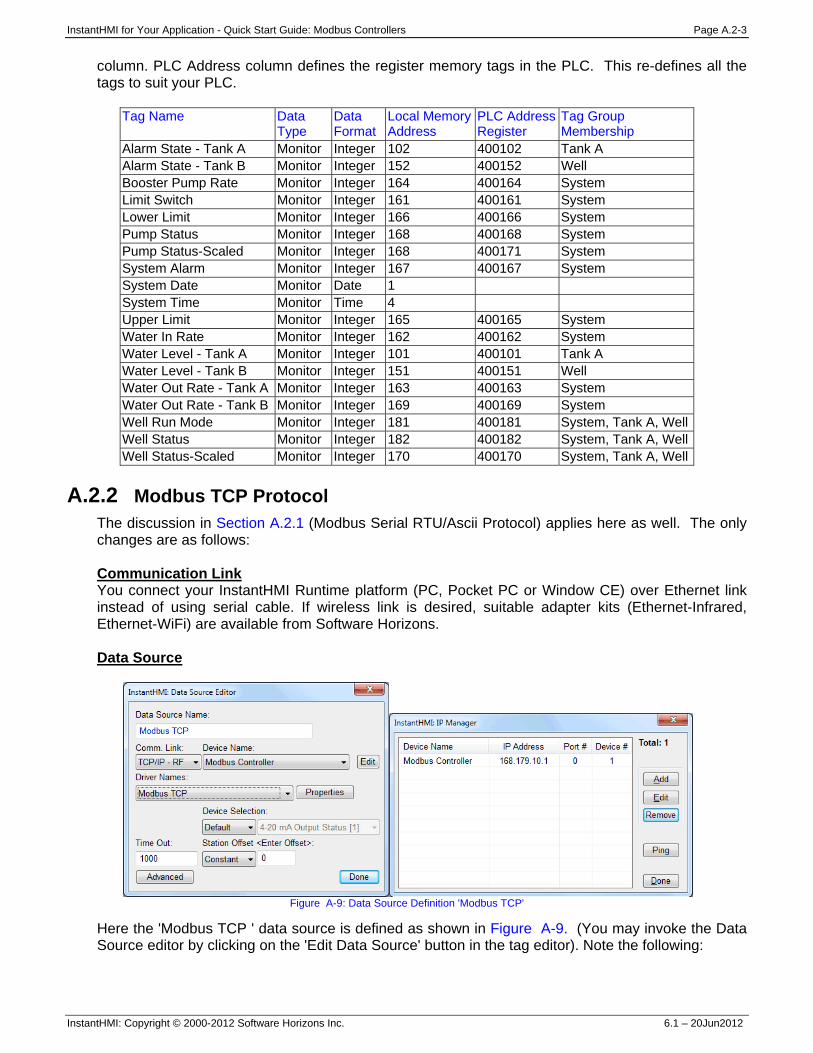
InstantHMI for Your Application - Quick Start Guide: Modbus Controllers Page A.2-3
InstantHMI: Copyright © 2000-2012 Software Horizons Inc. 6.1 – 20Jun2012
column. PLC Address column defines the register memory tags in the PLC. This re-defines all the tags to suit your PLC.
Tag Name Data Type
Data Format
Local Memory Address
PLC AddressRegister
Tag Group Membership
Alarm State - Tank A Monitor Integer 102 400102 Tank A Alarm State - Tank B Monitor Integer 152 400152 Well Booster Pump Rate Monitor Integer 164 400164 System Limit Switch Monitor Integer 161 400161 System Lower Limit Monitor Integer 166 400166 System Pump Status Monitor Integer 168 400168 System Pump Status-Scaled Monitor Integer 168 400171 System System Alarm Monitor Integer 167 400167 System System Date Monitor Date 1 System Time Monitor Time 4 Upper Limit Monitor Integer 165 400165 System Water In Rate Monitor Integer 162 400162 System Water Level - Tank A Monitor Integer 101 400101 Tank A Water Level - Tank B Monitor Integer 151 400151 Well Water Out Rate - Tank A Monitor Integer 163 400163 System Water Out Rate - Tank B Monitor Integer 169 400169 System Well Run Mode Monitor Integer 181 400181 System, Tank A, WellWell Status Monitor Integer 182 400182 System, Tank A, WellWell Status-Scaled Monitor Integer 170 400170 System, Tank A, Well
A.2.2 Modbus TCP Protocol
The discussion in Section A.2.1 (Modbus Serial RTU/Ascii Protocol) applies here as well. The only changes are as follows: Communication Link You connect your InstantHMI Runtime platform (PC, Pocket PC or Window CE) over Ethernet link instead of using serial cable. If wireless link is desired, suitable adapter kits (Ethernet-Infrared, Ethernet-WiFi) are available from Software Horizons. Data Source
Figure A-9: Data Source Definition 'Modbus TCP'
Here the 'Modbus TCP ' data source is defined as shown in Figure A-9. (You may invoke the Data Source editor by clicking on the 'Edit Data Source' button in the tag editor). Note the following:
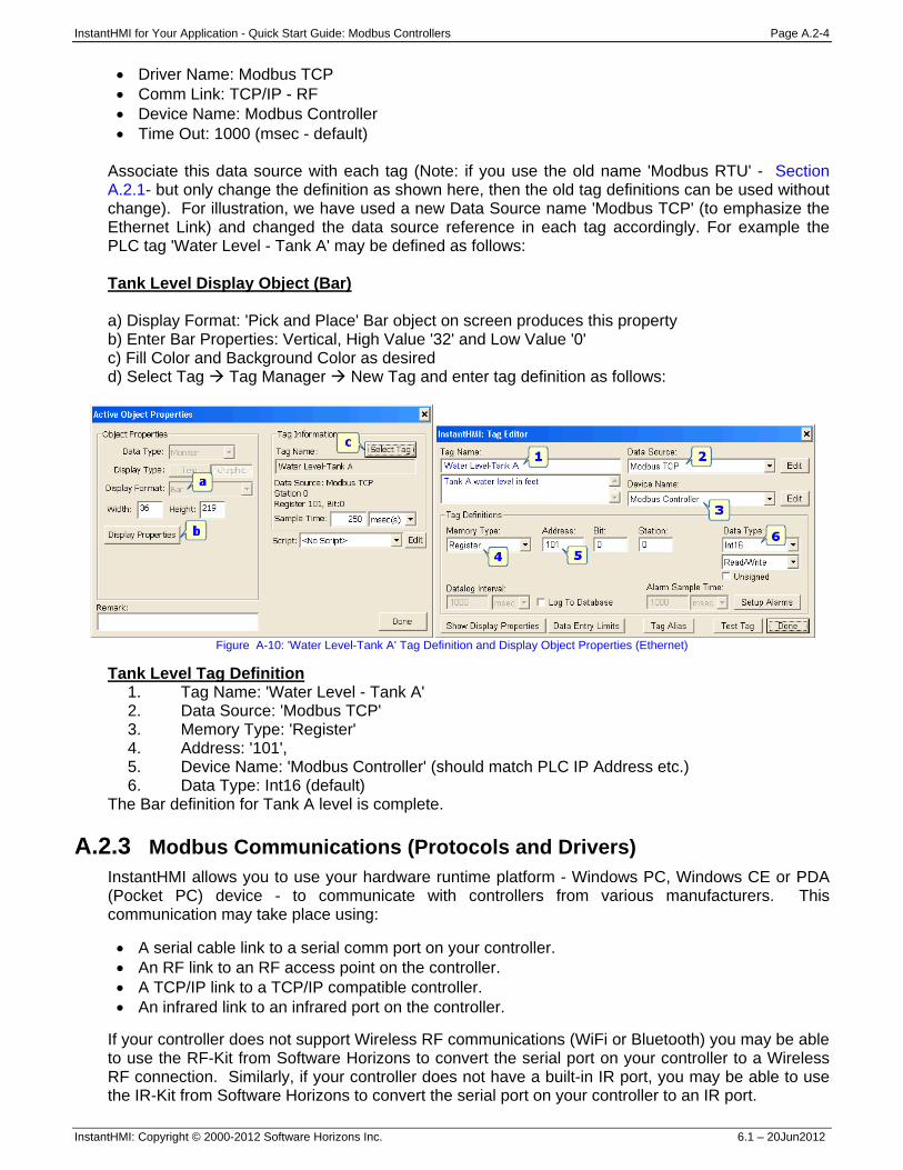
InstantHMI for Your Application - Quick Start Guide: Modbus Controllers Page A.2-4
InstantHMI: Copyright © 2000-2012 Software Horizons Inc. 6.1 – 20Jun2012
• Driver Name: Modbus TCP • Comm Link: TCP/IP - RF • Device Name: Modbus Controller • Time Out: 1000 (msec - default)
Associate this data source with each tag (Note: if you use the old name 'Modbus RTU' - Section A.2.1- but only change the definition as shown here, then the old tag definitions can be used without change). For illustration, we have used a new Data Source name 'Modbus TCP' (to emphasize the Ethernet Link) and changed the data source reference in each tag accordingly. For example the PLC tag 'Water Level - Tank A' may be defined as follows: Tank Level Display Object (Bar) a) Display Format: 'Pick and Place' Bar object on screen produces this property b) Enter Bar Properties: Vertical, High Value '32' and Low Value '0' c) Fill Color and Background Color as desired d) Select Tag Tag Manager New Tag and enter tag definition as follows:
Figure A-10: 'Water Level-Tank A' Tag Definition and Display Object Properties (Ethernet)
Tank Level Tag Definition 1. Tag Name: 'Water Level - Tank A' 2. Data Source: 'Modbus TCP' 3. Memory Type: 'Register' 4. Address: '101', 5. Device Name: 'Modbus Controller' (should match PLC IP Address etc.) 6. Data Type: Int16 (default)
The Bar definition for Tank A level is complete. A.2.3 Modbus Communications (Protocols and Drivers)
InstantHMI allows you to use your hardware runtime platform - Windows PC, Windows CE or PDA (Pocket PC) device - to communicate with controllers from various manufacturers. This communication may take place using: • A serial cable link to a serial comm port on your controller. • An RF link to an RF access point on the controller. • A TCP/IP link to a TCP/IP compatible controller. • An infrared link to an infrared port on the controller.
If your controller does not support Wireless RF communications (WiFi or Bluetooth) you may be able to use the RF-Kit from Software Horizons to convert the serial port on your controller to a Wireless RF connection. Similarly, if your controller does not have a built-in IR port, you may be able to use the IR-Kit from Software Horizons to convert the serial port on your controller to an IR port.
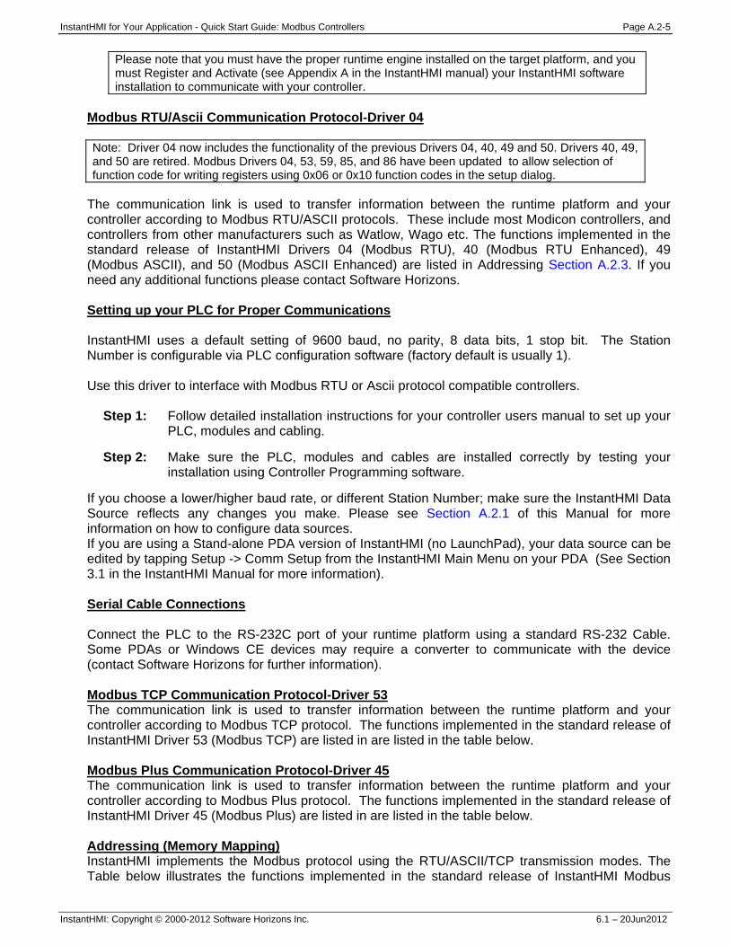
InstantHMI for Your Application - Quick Start Guide: Modbus Controllers Page A.2-5
InstantHMI: Copyright © 2000-2012 Software Horizons Inc. 6.1 – 20Jun2012
Please note that you must have the proper runtime engine installed on the target platform, and you must Register and Activate (see Appendix A in the InstantHMI manual) your InstantHMI software installation to communicate with your controller.
Modbus RTU/Ascii Communication Protocol-Driver 04 Note: Driver 04 now includes the functionality of the previous Drivers 04, 40, 49 and 50. Drivers 40, 49, and 50 are retired. Modbus Drivers 04, 53, 59, 85, and 86 have been updated to allow selection of function code for writing registers using 0x06 or 0x10 function codes in the setup dialog.
The communication link is used to transfer information between the runtime platform and your controller according to Modbus RTU/ASCII protocols. These include most Modicon controllers, and controllers from other manufacturers such as Watlow, Wago etc. The functions implemented in the standard release of InstantHMI Drivers 04 (Modbus RTU), 40 (Modbus RTU Enhanced), 49 (Modbus ASCII), and 50 (Modbus ASCII Enhanced) are listed in Addressing Section A.2.3. If you need any additional functions please contact Software Horizons. Setting up your PLC for Proper Communications InstantHMI uses a default setting of 9600 baud, no parity, 8 data bits, 1 stop bit. The Station Number is configurable via PLC configuration software (factory default is usually 1). Use this driver to interface with Modbus RTU or Ascii protocol compatible controllers.
Step 1: Follow detailed installation instructions for your controller users manual to set up your PLC, modules and cabling.
Step 2: Make sure the PLC, modules and cables are installed correctly by testing your
installation using Controller Programming software.
If you choose a lower/higher baud rate, or different Station Number; make sure the InstantHMI Data Source reflects any changes you make. Please see Section A.2.1 of this Manual for more information on how to configure data sources. If you are using a Stand-alone PDA version of InstantHMI (no LaunchPad), your data source can be edited by tapping Setup -> Comm Setup from the InstantHMI Main Menu on your PDA (See Section 3.1 in the InstantHMI Manual for more information). Serial Cable Connections Connect the PLC to the RS-232C port of your runtime platform using a standard RS-232 Cable. Some PDAs or Windows CE devices may require a converter to communicate with the device (contact Software Horizons for further information). Modbus TCP Communication Protocol-Driver 53 The communication link is used to transfer information between the runtime platform and your controller according to Modbus TCP protocol. The functions implemented in the standard release of InstantHMI Driver 53 (Modbus TCP) are listed in are listed in the table below. Modbus Plus Communication Protocol-Driver 45 The communication link is used to transfer information between the runtime platform and your controller according to Modbus Plus protocol. The functions implemented in the standard release of InstantHMI Driver 45 (Modbus Plus) are listed in are listed in the table below. Addressing (Memory Mapping) InstantHMI implements the Modbus protocol using the RTU/ASCII/TCP transmission modes. The Table below illustrates the functions implemented in the standard release of InstantHMI Modbus
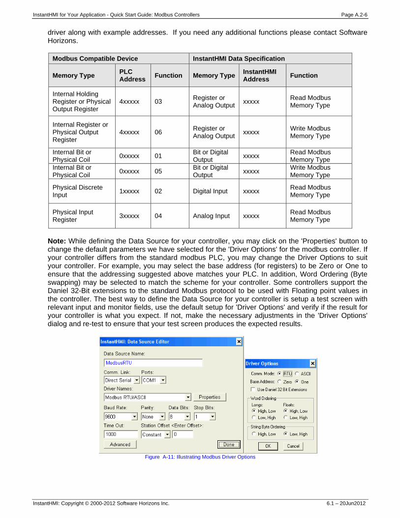
InstantHMI for Your Application - Quick Start Guide: Modbus Controllers Page A.2-6
InstantHMI: Copyright © 2000-2012 Software Horizons Inc. 6.1 – 20Jun2012
driver along with example addresses. If you need any additional functions please contact Software Horizons.
Modbus Compatible Device InstantHMI Data Specification
Memory Type PLC Address Function Memory Type InstantHMI
Address Function
Internal Holding Register or Physical Output Register
4xxxxx 03 Register or Analog Output xxxxx Read Modbus
Memory Type
Internal Register or Physical Output Register
4xxxxx 06 Register or Analog Output xxxxx Write Modbus
Memory Type
Internal Bit or Physical Coil 0xxxxx 01 Bit or Digital
Output xxxxx Read Modbus Memory Type
Internal Bit or Physical Coil 0xxxxx 05 Bit or Digital
Output xxxxx Write Modbus Memory Type
Physical Discrete Input 1xxxxx 02 Digital Input xxxxx Read Modbus
Memory Type
Physical Input Register 3xxxxx 04 Analog Input xxxxx Read Modbus
Memory Type
Note: While defining the Data Source for your controller, you may click on the 'Properties' button to change the default parameters we have selected for the 'Driver Options' for the modbus controller. If your controller differs from the standard modbus PLC, you may change the Driver Options to suit your controller. For example, you may select the base address (for registers) to be Zero or One to ensure that the addressing suggested above matches your PLC. In addition, Word Ordering (Byte swapping) may be selected to match the scheme for your controller. Some controllers support the Daniel 32-Bit extensions to the standard Modbus protocol to be used with Floating point values in the controller. The best way to define the Data Source for your controller is setup a test screen with relevant input and monitor fields, use the default setup for 'Driver Options' and verify if the result for your controller is what you expect. If not, make the necessary adjustments in the 'Driver Options' dialog and re-test to ensure that your test screen produces the expected results.
Figure A-11: Illustrating Modbus Driver Options
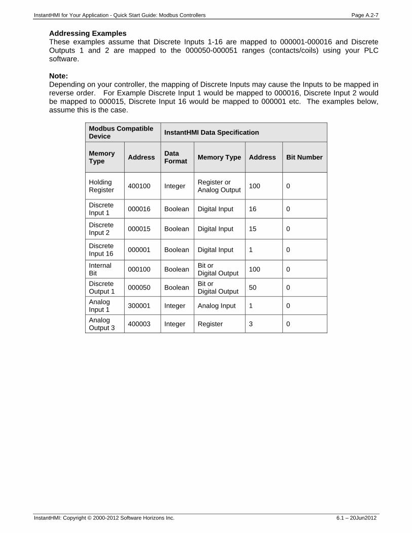
InstantHMI for Your Application - Quick Start Guide: Modbus Controllers Page A.2-7
InstantHMI: Copyright © 2000-2012 Software Horizons Inc. 6.1 – 20Jun2012
Addressing Examples These examples assume that Discrete Inputs 1-16 are mapped to 000001-000016 and Discrete Outputs 1 and 2 are mapped to the 000050-000051 ranges (contacts/coils) using your PLC software. Note: Depending on your controller, the mapping of Discrete Inputs may cause the Inputs to be mapped in reverse order. For Example Discrete Input 1 would be mapped to 000016, Discrete Input 2 would be mapped to 000015, Discrete Input 16 would be mapped to 000001 etc. The examples below, assume this is the case.
Modbus Compatible Device InstantHMI Data Specification
Memory Type Address Data
Format Memory Type Address Bit Number
Holding Register 400100 Integer Register or
Analog Output 100 0
Discrete Input 1 000016 Boolean Digital Input 16 0
Discrete Input 2 000015 Boolean Digital Input 15 0
Discrete Input 16 000001 Boolean Digital Input 1 0
Internal Bit 000100 Boolean Bit or
Digital Output 100 0
Discrete Output 1 000050 Boolean Bit or
Digital Output 50 0
Analog Input 1 300001 Integer Analog Input 1 0
Analog Output 3 400003 Integer Register 3 0

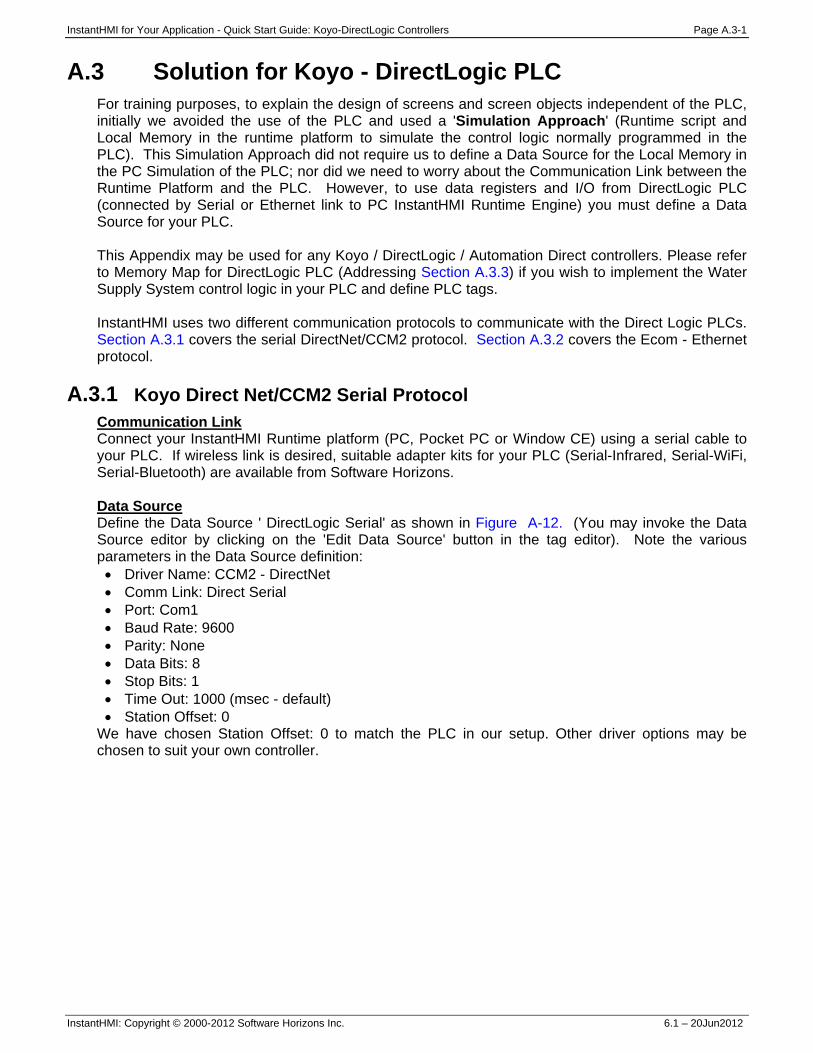
InstantHMI for Your Application - Quick Start Guide: Koyo-DirectLogic Controllers Page A.3-1
InstantHMI: Copyright © 2000-2012 Software Horizons Inc. 6.1 – 20Jun2012
A.3 Solution for Koyo - DirectLogic PLC For training purposes, to explain the design of screens and screen objects independent of the PLC, initially we avoided the use of the PLC and used a 'Simulation Approach' (Runtime script and Local Memory in the runtime platform to simulate the control logic normally programmed in the PLC). This Simulation Approach did not require us to define a Data Source for the Local Memory in the PC Simulation of the PLC; nor did we need to worry about the Communication Link between the Runtime Platform and the PLC. However, to use data registers and I/O from DirectLogic PLC (connected by Serial or Ethernet link to PC InstantHMI Runtime Engine) you must define a Data Source for your PLC. This Appendix may be used for any Koyo / DirectLogic / Automation Direct controllers. Please refer to Memory Map for DirectLogic PLC (Addressing Section A.3.3) if you wish to implement the Water Supply System control logic in your PLC and define PLC tags. InstantHMI uses two different communication protocols to communicate with the Direct Logic PLCs. Section A.3.1 covers the serial DirectNet/CCM2 protocol. Section A.3.2 covers the Ecom - Ethernet protocol.
A.3.1 Koyo Direct Net/CCM2 Serial Protocol Communication Link Connect your InstantHMI Runtime platform (PC, Pocket PC or Window CE) using a serial cable to your PLC. If wireless link is desired, suitable adapter kits for your PLC (Serial-Infrared, Serial-WiFi, Serial-Bluetooth) are available from Software Horizons. Data Source Define the Data Source ' DirectLogic Serial' as shown in Figure A-12. (You may invoke the Data Source editor by clicking on the 'Edit Data Source' button in the tag editor). Note the various parameters in the Data Source definition: • Driver Name: CCM2 - DirectNet • Comm Link: Direct Serial • Port: Com1 • Baud Rate: 9600 • Parity: None • Data Bits: 8 • Stop Bits: 1 • Time Out: 1000 (msec - default) • Station Offset: 0
We have chosen Station Offset: 0 to match the PLC in our setup. Other driver options may be chosen to suit your own controller.
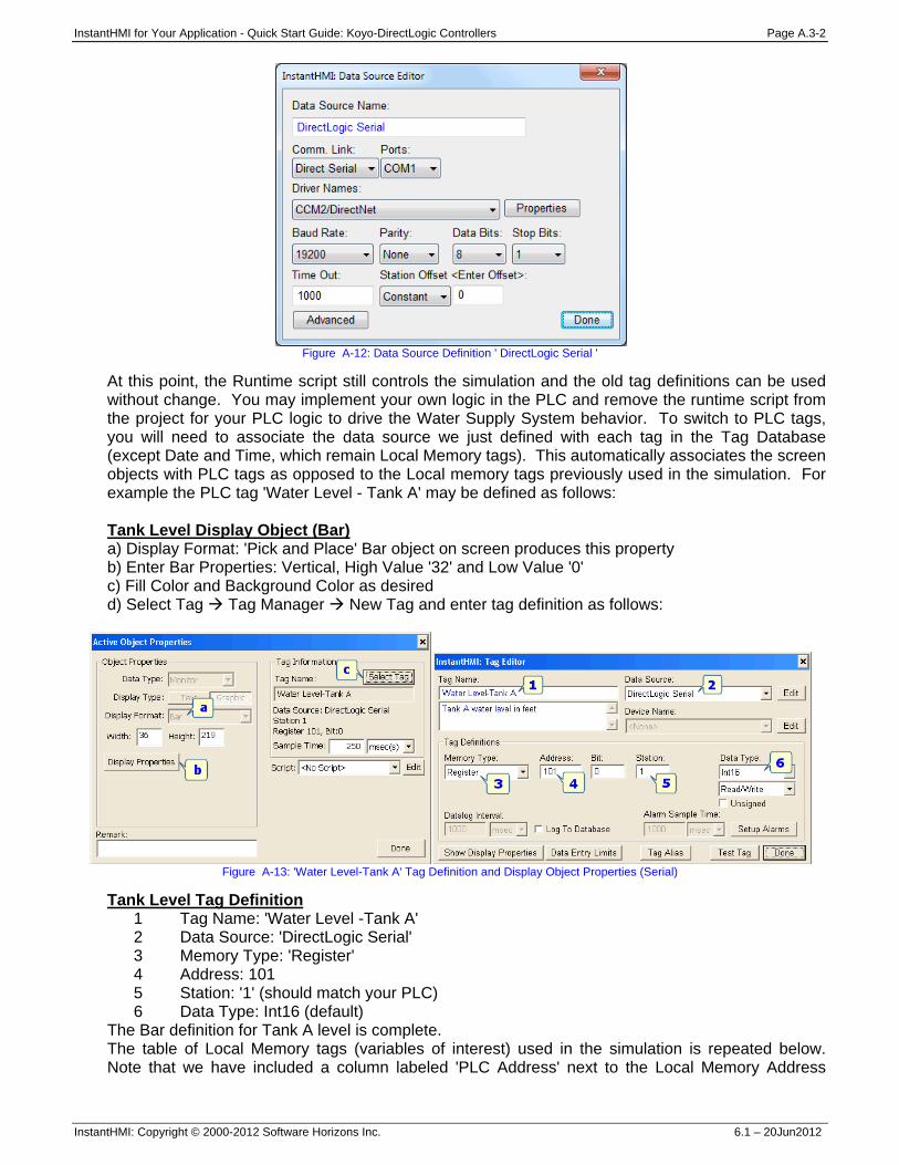
InstantHMI for Your Application - Quick Start Guide: Koyo-DirectLogic Controllers Page A.3-2
InstantHMI: Copyright © 2000-2012 Software Horizons Inc. 6.1 – 20Jun2012
Figure A-12: Data Source Definition ' DirectLogic Serial '
At this point, the Runtime script still controls the simulation and the old tag definitions can be used without change. You may implement your own logic in the PLC and remove the runtime script from the project for your PLC logic to drive the Water Supply System behavior. To switch to PLC tags, you will need to associate the data source we just defined with each tag in the Tag Database (except Date and Time, which remain Local Memory tags). This automatically associates the screen objects with PLC tags as opposed to the Local memory tags previously used in the simulation. For example the PLC tag 'Water Level - Tank A' may be defined as follows: Tank Level Display Object (Bar) a) Display Format: 'Pick and Place' Bar object on screen produces this property b) Enter Bar Properties: Vertical, High Value '32' and Low Value '0' c) Fill Color and Background Color as desired d) Select Tag Tag Manager New Tag and enter tag definition as follows:
Figure A-13: 'Water Level-Tank A' Tag Definition and Display Object Properties (Serial)
Tank Level Tag Definition 1 Tag Name: 'Water Level -Tank A' 2 Data Source: 'DirectLogic Serial' 3 Memory Type: 'Register' 4 Address: 101 5 Station: '1' (should match your PLC) 6 Data Type: Int16 (default)
The Bar definition for Tank A level is complete. The table of Local Memory tags (variables of interest) used in the simulation is repeated below. Note that we have included a column labeled 'PLC Address' next to the Local Memory Address
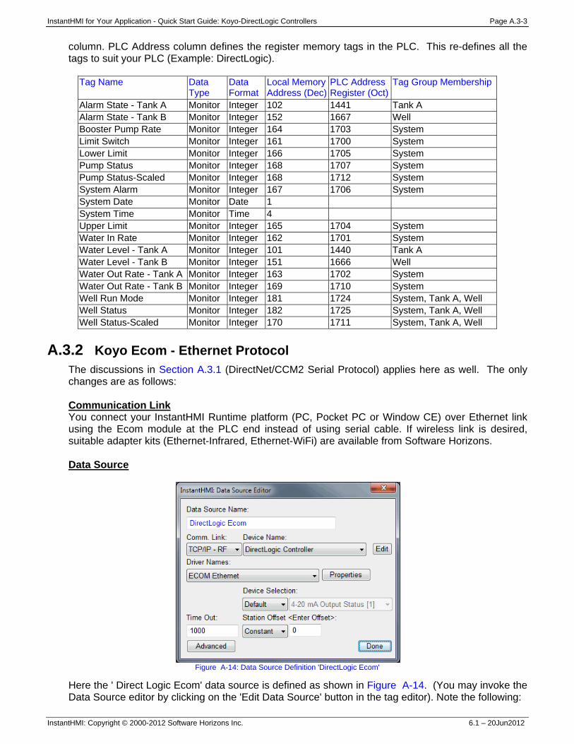
InstantHMI for Your Application - Quick Start Guide: Koyo-DirectLogic Controllers Page A.3-3
InstantHMI: Copyright © 2000-2012 Software Horizons Inc. 6.1 – 20Jun2012
column. PLC Address column defines the register memory tags in the PLC. This re-defines all the tags to suit your PLC (Example: DirectLogic).
Tag Name Data Type
Data Format
Local Memory Address (Dec)
PLC Address Register (Oct)
Tag Group Membership
Alarm State - Tank A Monitor Integer 102 1441 Tank A Alarm State - Tank B Monitor Integer 152 1667 Well Booster Pump Rate Monitor Integer 164 1703 System Limit Switch Monitor Integer 161 1700 System Lower Limit Monitor Integer 166 1705 System Pump Status Monitor Integer 168 1707 System Pump Status-Scaled Monitor Integer 168 1712 System System Alarm Monitor Integer 167 1706 System System Date Monitor Date 1 System Time Monitor Time 4 Upper Limit Monitor Integer 165 1704 System Water In Rate Monitor Integer 162 1701 System Water Level - Tank A Monitor Integer 101 1440 Tank A Water Level - Tank B Monitor Integer 151 1666 Well Water Out Rate - Tank A Monitor Integer 163 1702 System Water Out Rate - Tank B Monitor Integer 169 1710 System Well Run Mode Monitor Integer 181 1724 System, Tank A, Well Well Status Monitor Integer 182 1725 System, Tank A, Well Well Status-Scaled Monitor Integer 170 1711 System, Tank A, Well
A.3.2 Koyo Ecom - Ethernet Protocol
The discussions in Section A.3.1 (DirectNet/CCM2 Serial Protocol) applies here as well. The only changes are as follows: Communication Link You connect your InstantHMI Runtime platform (PC, Pocket PC or Window CE) over Ethernet link using the Ecom module at the PLC end instead of using serial cable. If wireless link is desired, suitable adapter kits (Ethernet-Infrared, Ethernet-WiFi) are available from Software Horizons. Data Source
Figure A-14: Data Source Definition 'DirectLogic Ecom'
Here the ' Direct Logic Ecom' data source is defined as shown in Figure A-14. (You may invoke the Data Source editor by clicking on the 'Edit Data Source' button in the tag editor). Note the following:
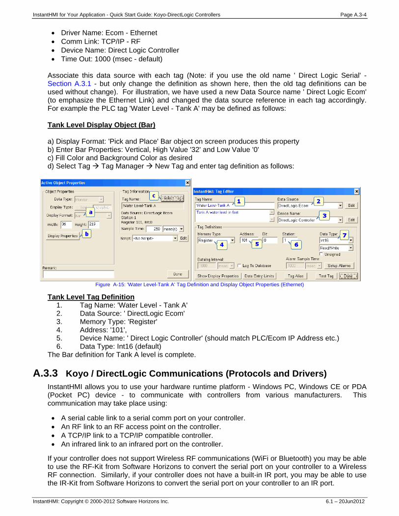
InstantHMI for Your Application - Quick Start Guide: Koyo-DirectLogic Controllers Page A.3-4
InstantHMI: Copyright © 2000-2012 Software Horizons Inc. 6.1 – 20Jun2012
• Driver Name: Ecom - Ethernet • Comm Link: TCP/IP - RF • Device Name: Direct Logic Controller • Time Out: 1000 (msec - default)
Associate this data source with each tag (Note: if you use the old name ' Direct Logic Serial' - Section A.3.1 - but only change the definition as shown here, then the old tag definitions can be used without change). For illustration, we have used a new Data Source name ' Direct Logic Ecom' (to emphasize the Ethernet Link) and changed the data source reference in each tag accordingly. For example the PLC tag 'Water Level - Tank A' may be defined as follows: Tank Level Display Object (Bar) a) Display Format: 'Pick and Place' Bar object on screen produces this property b) Enter Bar Properties: Vertical, High Value '32' and Low Value '0' c) Fill Color and Background Color as desired d) Select Tag Tag Manager New Tag and enter tag definition as follows:
Figure A-15: 'Water Level-Tank A' Tag Definition and Display Object Properties (Ethernet)
Tank Level Tag Definition 1. Tag Name: 'Water Level - Tank A' 2. Data Source: ' DirectLogic Ecom' 3. Memory Type: 'Register' 4. Address: '101', 5. Device Name: ' Direct Logic Controller' (should match PLC/Ecom IP Address etc.) 6. Data Type: Int16 (default)
The Bar definition for Tank A level is complete. A.3.3 Koyo / DirectLogic Communications (Protocols and Drivers)
InstantHMI allows you to use your hardware runtime platform - Windows PC, Windows CE or PDA (Pocket PC) device - to communicate with controllers from various manufacturers. This communication may take place using: • A serial cable link to a serial comm port on your controller. • An RF link to an RF access point on the controller. • A TCP/IP link to a TCP/IP compatible controller. • An infrared link to an infrared port on the controller.
If your controller does not support Wireless RF communications (WiFi or Bluetooth) you may be able to use the RF-Kit from Software Horizons to convert the serial port on your controller to a Wireless RF connection. Similarly, if your controller does not have a built-in IR port, you may be able to use the IR-Kit from Software Horizons to convert the serial port on your controller to an IR port.
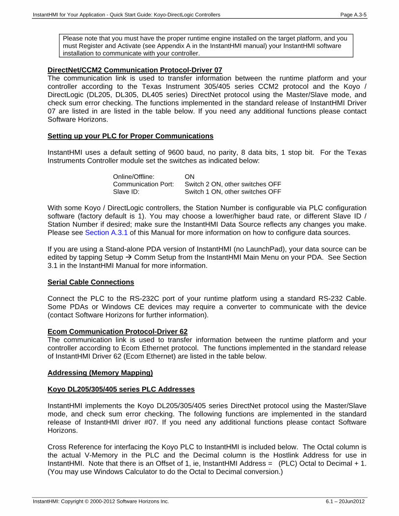
InstantHMI for Your Application - Quick Start Guide: Koyo-DirectLogic Controllers Page A.3-5
InstantHMI: Copyright © 2000-2012 Software Horizons Inc. 6.1 – 20Jun2012
Please note that you must have the proper runtime engine installed on the target platform, and you must Register and Activate (see Appendix A in the InstantHMI manual) your InstantHMI software installation to communicate with your controller.
DirectNet/CCM2 Communication Protocol-Driver 07 The communication link is used to transfer information between the runtime platform and your controller according to the Texas Instrument 305/405 series CCM2 protocol and the Koyo / DirectLogic (DL205, DL305, DL405 series) DirectNet protocol using the Master/Slave mode, and check sum error checking. The functions implemented in the standard release of InstantHMI Driver 07 are listed in are listed in the table below. If you need any additional functions please contact Software Horizons. Setting up your PLC for Proper Communications InstantHMI uses a default setting of 9600 baud, no parity, 8 data bits, 1 stop bit. For the Texas Instruments Controller module set the switches as indicated below:
Online/Offline: ON Communication Port: Switch 2 ON, other switches OFF Slave ID: Switch 1 ON, other switches OFF
With some Koyo / DirectLogic controllers, the Station Number is configurable via PLC configuration software (factory default is 1). You may choose a lower/higher baud rate, or different Slave ID / Station Number if desired; make sure the InstantHMI Data Source reflects any changes you make. Please see Section A.3.1 of this Manual for more information on how to configure data sources. If you are using a Stand-alone PDA version of InstantHMI (no LaunchPad), your data source can be edited by tapping Setup Comm Setup from the InstantHMI Main Menu on your PDA. See Section 3.1 in the InstantHMI Manual for more information. Serial Cable Connections Connect the PLC to the RS-232C port of your runtime platform using a standard RS-232 Cable. Some PDAs or Windows CE devices may require a converter to communicate with the device (contact Software Horizons for further information). Ecom Communication Protocol-Driver 62 The communication link is used to transfer information between the runtime platform and your controller according to Ecom Ethernet protocol. The functions implemented in the standard release of InstantHMI Driver 62 (Ecom Ethernet) are listed in the table below. Addressing (Memory Mapping) Koyo DL205/305/405 series PLC Addresses InstantHMI implements the Koyo DL205/305/405 series DirectNet protocol using the Master/Slave mode, and check sum error checking. The following functions are implemented in the standard release of InstantHMI driver #07. If you need any additional functions please contact Software Horizons. Cross Reference for interfacing the Koyo PLC to InstantHMI is included below. The Octal column is the actual V-Memory in the PLC and the Decimal column is the Hostlink Address for use in InstantHMI. Note that there is an Offset of 1, ie, InstantHMI Address = (PLC) Octal to Decimal + 1. (You may use Windows Calculator to do the Octal to Decimal conversion.)
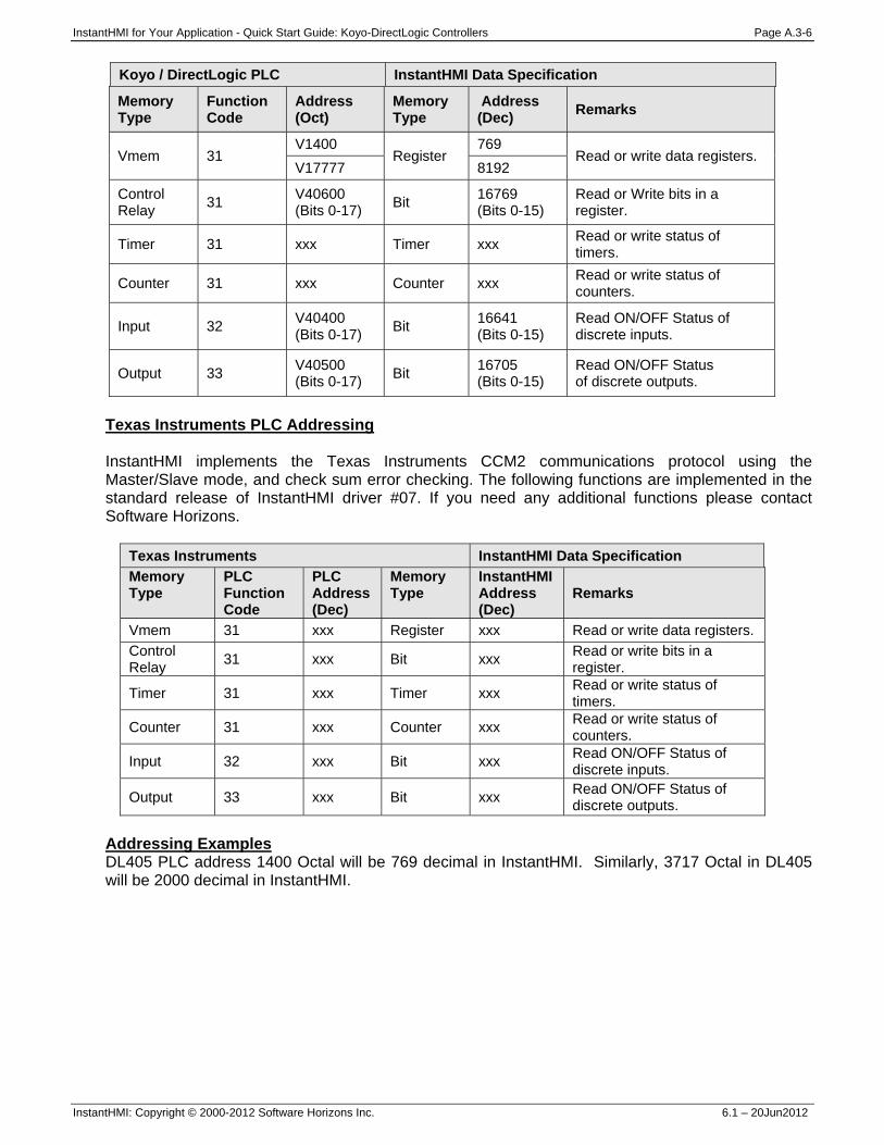
InstantHMI for Your Application - Quick Start Guide: Koyo-DirectLogic Controllers Page A.3-6
InstantHMI: Copyright © 2000-2012 Software Horizons Inc. 6.1 – 20Jun2012
Koyo / DirectLogic PLC InstantHMI Data Specification
Memory Type
Function Code
Address (Oct)
Memory Type
Address (Dec) Remarks
Vmem 31 V1400
Register 769
Read or write data registers. V17777 8192
Control Relay 31 V40600
(Bits 0-17) Bit 16769 (Bits 0-15)
Read or Write bits in a register.
Timer 31 xxx Timer xxx Read or write status of timers.
Counter 31 xxx Counter xxx Read or write status of counters.
Input 32 V40400 (Bits 0-17) Bit 16641
(Bits 0-15) Read ON/OFF Status of discrete inputs.
Output 33 V40500 (Bits 0-17) Bit 16705
(Bits 0-15) Read ON/OFF Status of discrete outputs.
Texas Instruments PLC Addressing InstantHMI implements the Texas Instruments CCM2 communications protocol using the Master/Slave mode, and check sum error checking. The following functions are implemented in the standard release of InstantHMI driver #07. If you need any additional functions please contact Software Horizons.
Texas Instruments InstantHMI Data Specification Memory Type
PLC Function Code
PLC Address (Dec)
Memory Type
InstantHMI Address (Dec)
Remarks
Vmem 31 xxx Register xxx Read or write data registers. Control Relay 31 xxx Bit xxx Read or write bits in a
register.
Timer 31 xxx Timer xxx Read or write status of timers.
Counter 31 xxx Counter xxx Read or write status of counters.
Input 32 xxx Bit xxx Read ON/OFF Status of discrete inputs.
Output 33 xxx Bit xxx Read ON/OFF Status of discrete outputs.
Addressing Examples DL405 PLC address 1400 Octal will be 769 decimal in InstantHMI. Similarly, 3717 Octal in DL405 will be 2000 decimal in InstantHMI.
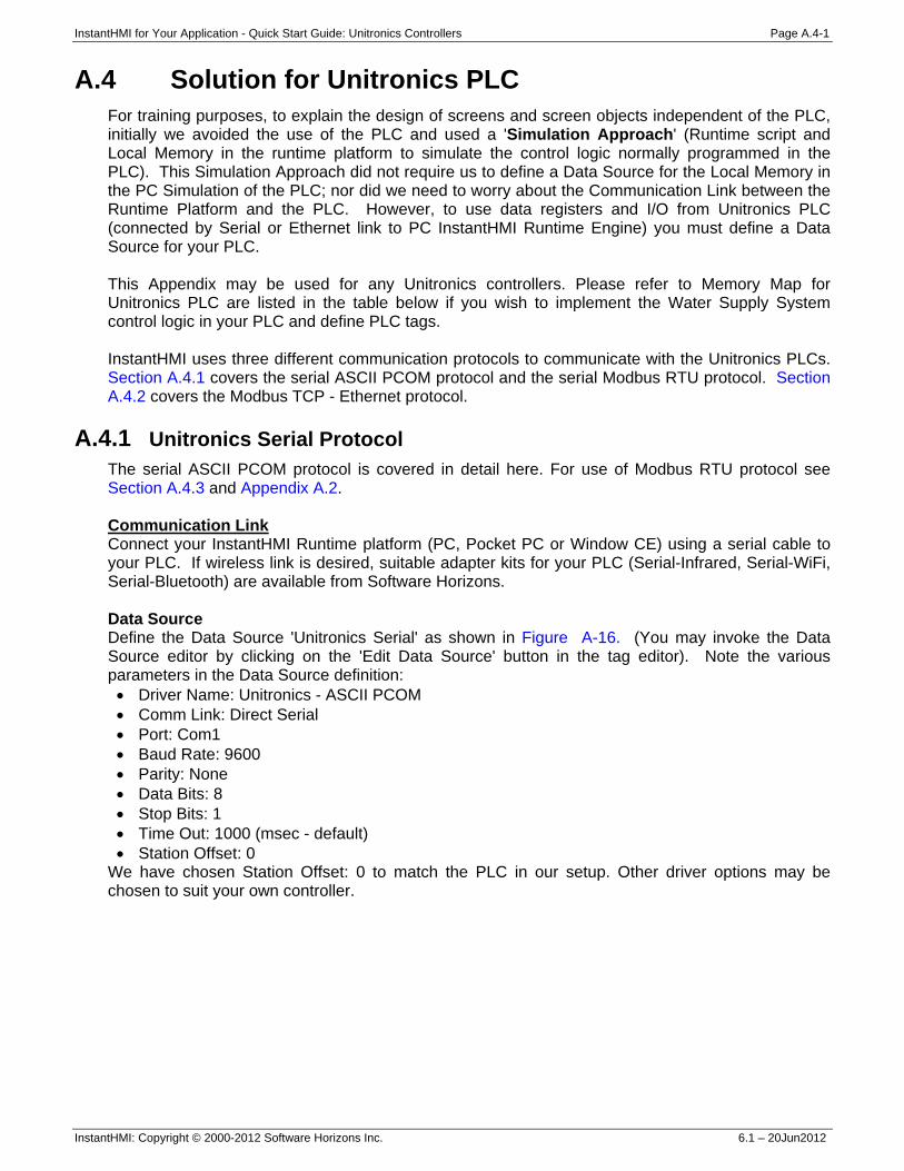
InstantHMI for Your Application - Quick Start Guide: Unitronics Controllers Page A.4-1
InstantHMI: Copyright © 2000-2012 Software Horizons Inc. 6.1 – 20Jun2012
A.4 Solution for Unitronics PLC For training purposes, to explain the design of screens and screen objects independent of the PLC, initially we avoided the use of the PLC and used a 'Simulation Approach' (Runtime script and Local Memory in the runtime platform to simulate the control logic normally programmed in the PLC). This Simulation Approach did not require us to define a Data Source for the Local Memory in the PC Simulation of the PLC; nor did we need to worry about the Communication Link between the Runtime Platform and the PLC. However, to use data registers and I/O from Unitronics PLC (connected by Serial or Ethernet link to PC InstantHMI Runtime Engine) you must define a Data Source for your PLC. This Appendix may be used for any Unitronics controllers. Please refer to Memory Map for Unitronics PLC are listed in the table below if you wish to implement the Water Supply System control logic in your PLC and define PLC tags. InstantHMI uses three different communication protocols to communicate with the Unitronics PLCs. Section A.4.1 covers the serial ASCII PCOM protocol and the serial Modbus RTU protocol. Section A.4.2 covers the Modbus TCP - Ethernet protocol.
A.4.1 Unitronics Serial Protocol The serial ASCII PCOM protocol is covered in detail here. For use of Modbus RTU protocol see Section A.4.3 and Appendix A.2. Communication Link Connect your InstantHMI Runtime platform (PC, Pocket PC or Window CE) using a serial cable to your PLC. If wireless link is desired, suitable adapter kits for your PLC (Serial-Infrared, Serial-WiFi, Serial-Bluetooth) are available from Software Horizons. Data Source Define the Data Source 'Unitronics Serial' as shown in Figure A-16. (You may invoke the Data Source editor by clicking on the 'Edit Data Source' button in the tag editor). Note the various parameters in the Data Source definition: • Driver Name: Unitronics - ASCII PCOM • Comm Link: Direct Serial • Port: Com1 • Baud Rate: 9600 • Parity: None • Data Bits: 8 • Stop Bits: 1 • Time Out: 1000 (msec - default) • Station Offset: 0
We have chosen Station Offset: 0 to match the PLC in our setup. Other driver options may be chosen to suit your own controller.
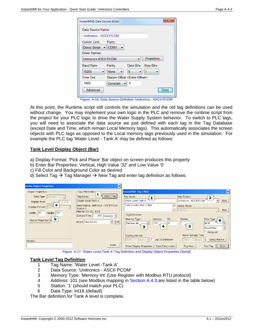
InstantHMI for Your Application - Quick Start Guide: Unitronics Controllers Page A.4-2
InstantHMI: Copyright © 2000-2012 Software Horizons Inc. 6.1 – 20Jun2012
Figure A-16: Data Source Definition 'Unitronics - ASCII PCOM'
At this point, the Runtime script still controls the simulation and the old tag definitions can be used without change. You may implement your own logic in the PLC and remove the runtime script from the project for your PLC logic to drive the Water Supply System behavior. To switch to PLC tags, you will need to associate the data source we just defined with each tag in the Tag Database (except Date and Time, which remain Local Memory tags). This automatically associates the screen objects with PLC tags as opposed to the Local memory tags previously used in the simulation. For example the PLC tag 'Water Level - Tank A' may be defined as follows: Tank Level Display Object (Bar) a) Display Format: 'Pick and Place' Bar object on screen produces this property b) Enter Bar Properties: Vertical, High Value '32' and Low Value '0' c) Fill Color and Background Color as desired d) Select Tag Tag Manager New Tag and enter tag definition as follows:
Figure A-17: 'Water Level-Tank A' Tag Definition and Display Object Properties (Serial)
Tank Level Tag Definition 1 Tag Name: 'Water Level -Tank A' 2 Data Source: 'Unitronics - ASCII PCOM' 3 Memory Type: 'Memory Int' (Use Register with Modbus RTU protocol) 4 Address: 101 (see Modbus mapping in Section A.4.3 are listed in the table below) 5 Station: '1' (should match your PLC) 6 Data Type: Int16 (default)
The Bar definition for Tank A level is complete.
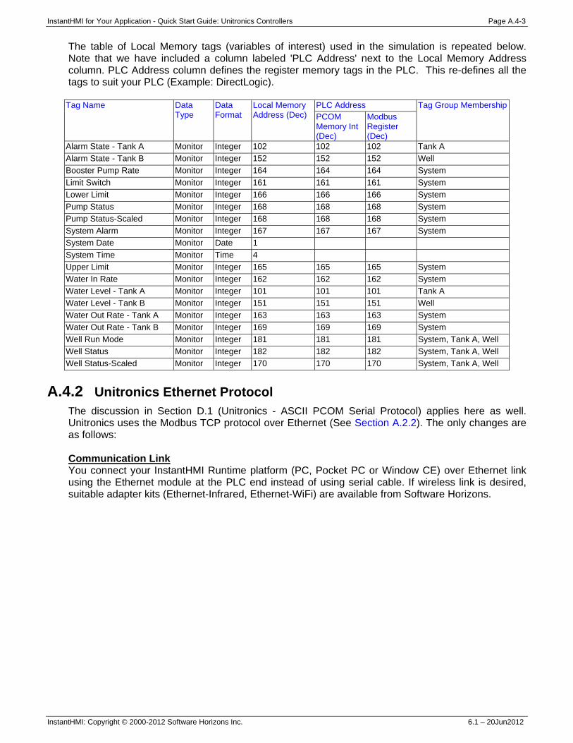
InstantHMI for Your Application - Quick Start Guide: Unitronics Controllers Page A.4-3
InstantHMI: Copyright © 2000-2012 Software Horizons Inc. 6.1 – 20Jun2012
The table of Local Memory tags (variables of interest) used in the simulation is repeated below. Note that we have included a column labeled 'PLC Address' next to the Local Memory Address column. PLC Address column defines the register memory tags in the PLC. This re-defines all the tags to suit your PLC (Example: DirectLogic).
Tag Name Data Type
Data Format
Local Memory Address (Dec)
PLC Address Tag Group MembershipPCOM Memory Int (Dec)
Modbus Register (Dec)
Alarm State - Tank A Monitor Integer 102 102 102 Tank A Alarm State - Tank B Monitor Integer 152 152 152 Well Booster Pump Rate Monitor Integer 164 164 164 System Limit Switch Monitor Integer 161 161 161 System Lower Limit Monitor Integer 166 166 166 System Pump Status Monitor Integer 168 168 168 System Pump Status-Scaled Monitor Integer 168 168 168 System System Alarm Monitor Integer 167 167 167 System System Date Monitor Date 1 System Time Monitor Time 4 Upper Limit Monitor Integer 165 165 165 System Water In Rate Monitor Integer 162 162 162 System Water Level - Tank A Monitor Integer 101 101 101 Tank A Water Level - Tank B Monitor Integer 151 151 151 Well Water Out Rate - Tank A Monitor Integer 163 163 163 System Water Out Rate - Tank B Monitor Integer 169 169 169 System Well Run Mode Monitor Integer 181 181 181 System, Tank A, Well Well Status Monitor Integer 182 182 182 System, Tank A, Well Well Status-Scaled Monitor Integer 170 170 170 System, Tank A, Well
A.4.2 Unitronics Ethernet Protocol The discussion in Section D.1 (Unitronics - ASCII PCOM Serial Protocol) applies here as well. Unitronics uses the Modbus TCP protocol over Ethernet (See Section A.2.2). The only changes are as follows: Communication Link You connect your InstantHMI Runtime platform (PC, Pocket PC or Window CE) over Ethernet link using the Ethernet module at the PLC end instead of using serial cable. If wireless link is desired, suitable adapter kits (Ethernet-Infrared, Ethernet-WiFi) are available from Software Horizons.
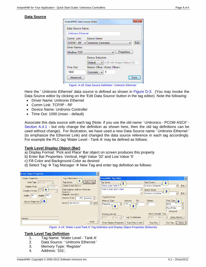
InstantHMI for Your Application - Quick Start Guide: Unitronics Controllers Page A.4-4
InstantHMI: Copyright © 2000-2012 Software Horizons Inc. 6.1 – 20Jun2012
Data Source
Figure A-18: Data Source Definition ' Unitronix Ethernet '
Here the ' Unitronix Ethernet' data source is defined as shown in Figure D-3. (You may invoke the Data Source editor by clicking on the 'Edit Data Source' button in the tag editor). Note the following: • Driver Name: Unitronix Ethernet • Comm Link: TCP/IP - RF • Device Name: Unitronix Controller • Time Out: 1000 (msec - default)
Associate this data source with each tag (Note: if you use the old name ' Unitronics - PCOM ASCII' - Section A.4.1 - but only change the definition as shown here, then the old tag definitions can be used without change). For illustration, we have used a new Data Source name ' Unitronix Ethernet ' (to emphasize the Ethernet Link) and changed the data source reference in each tag accordingly. For example the PLC tag 'Water Level - Tank A' may be defined as follows: Tank Level Display Object (Bar) a) Display Format: 'Pick and Place' Bar object on screen produces this property b) Enter Bar Properties: Vertical, High Value '32' and Low Value '0' c) Fill Color and Background Color as desired d) Select Tag Tag Manager New Tag and enter tag definition as follows:
Figure A-19: 'Water Level-Tank A' Tag Definition and Display Object Properties (Ethernet)
Tank Level Tag Definition 1. Tag Name: 'Water Level - Tank A' 2. Data Source: ' Unitronix Ethernet ' 3. Memory Type: 'Register' 4. Address: '101',
InstantHMI for Your Application - Quick Start Guide: Unitronics Controllers Page A.4-5
InstantHMI: Copyright © 2000-2012 Software Horizons Inc. 6.1 – 20Jun2012
5. Device Name: ' Unitronix Controller' (should match PLC/Ecom IP Address etc.) 6. Data Type: Int16 (default)
The Bar definition for Tank A level is complete. A.4.3 Unitronics (Protocols and Drivers)
InstantHMI allows you to use your hardware runtime platform - Windows PC, Windows CE or PDA (Pocket PC) device - to communicate with controllers from various manufacturers. This communication may take place using: • A serial cable link to a serial comm port on your controller. • An RF link to an RF access point on the controller. • A TCP/IP link to a TCP/IP compatible controller. • An infrared link to an infrared port on the controller.
If your controller does not support Wireless RF communications (WiFi or Bluetooth) you may be able to use the RF-Kit from Software Horizons to convert the serial port on your controller to a Wireless RF connection. Similarly, if your controller does not have a built-in IR port, you may be able to use the IR-Kit from Software Horizons to convert the serial port on your controller to an IR port.
Please note that you must have the proper runtime engine installed on the target platform, and you must Register and Activate (see Appendix A in the InstantHMI manual) your InstantHMI software installation to communicate with your controller.
Unitronics Serial Communication Protocol-Driver 54 The communication link is used to transfer information between the runtime platform and your controller according to the Unitronics PCOM ASCII protocol. The functions implemented in the standard release of InstantHMI Driver 54 are listed in are listed in the table below. If you need any additional functions please contact Software Horizons. Note: Unitronix also supports Modbus RTU protocol (See Section A.2.1). Setting up your PLC for Proper Communications InstantHMI uses a default setting of 9600 baud, no parity, 8 data bits, 1 stop bit. The Station Number is configurable via PLC configuration software (factory default is 1). You may choose a lower/higher baud rate, or different Station Number if desired; make sure the InstantHMI Data Source reflects any changes you make. Please see Section A.4.1 of this Manual for more information on how to configure data sources. If you are using a Stand-alone PDA version of InstantHMI (no LaunchPad), your data source can be edited by tapping Setup Comm Setup from the InstantHMI Main Menu on your PDA. See Section 3.1 in the InstantHMI Manual for more information. Serial Cable Connections Connect the PLC to the RS-232C port of your runtime platform using a standard RS-232 Cable. Some PDAs or Windows CE devices may require a converter to communicate with the device (contact Software Horizons for further information). Unitronix Ethernet Communication Protocol-Driver 53 The communication link is used to transfer information between the runtime platform and your controller according to Modbus TCP protocol. The functions implemented in the standard release of InstantHMI Driver 53 (Modbus TCP) are listed in Section A.2.3.
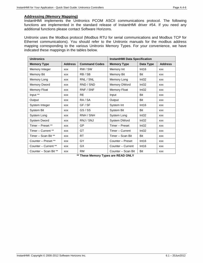
InstantHMI for Your Application - Quick Start Guide: Unitronics Controllers Page A.4-6
InstantHMI: Copyright © 2000-2012 Software Horizons Inc. 6.1 – 20Jun2012
Addressing (Memory Mapping) InstantHMI implements the Unitronics PCOM ASCII communications protocol. The following functions are implemented in the standard release of InstantHMI driver #54. If you need any additional functions please contact Software Horizons. Unitronix uses the Modbus protocol (Modbus RTU for serial communications and Modbus TCP for Ethernet communications). You should refer to the Unitronix manuals for the modbus address mapping corresponding to the various Unitronix Memory Types. For your convenience, we have indicated these mappings in the tables below.
Unitronics InstantHMI Data Specification Memory Type Address Command Codes Memory Type Data Type Address Memory Integer xxx RW / SW Memory Int Int16 xxx
Memory Bit xxx RB / SB Memory Bit Bit xxx
Memory Long xxx RNL / SNL Memory Long Int32 xxx
Memory Dword xxx RND / SND Memory DWord Int32 xxx
Memory Float xxx RNF / SNF Memory Float Int32 xxx
Input ** xxx RE Input Bit xxx
Output xxx RA / SA Output Bit xxx
System Integer xxx GF / SF System Int Int16 xxx
System Bit xxx GS / SS System Bit Bit xxx
System Long xxx RNH / SNH System Long Int32 xxx
System Dword xxx RNJ / SNJ System DWord Int32 xxx
Timer – Preset ** xxx GP Timer – Preset Int32 xxx
Timer – Current ** xxx GT Timer – Current Int32 xxx
Timer – Scan Bit ** xxx RT Timer – Scan Bit Bit xxx
Counter – Preset ** xxx GY Counter – Preset Int16 xxx
Counter – Current ** xxx GX Counter – Current Int16 xxx
Counter – Scan Bit ** xxx RM Counter – Scan Bit Bit xxx ** These Memory Types are READ ONLY
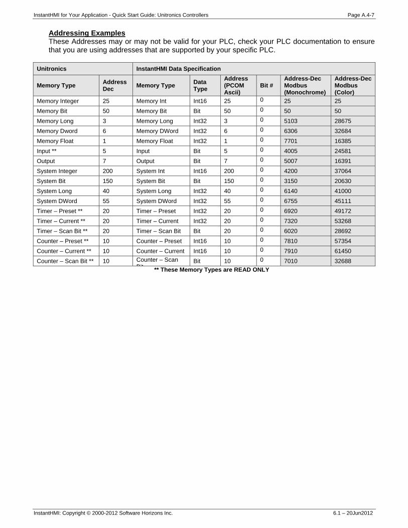
InstantHMI for Your Application - Quick Start Guide: Unitronics Controllers Page A.4-7
InstantHMI: Copyright © 2000-2012 Software Horizons Inc. 6.1 – 20Jun2012
Addressing Examples These Addresses may or may not be valid for your PLC, check your PLC documentation to ensure that you are using addresses that are supported by your specific PLC.
Unitronics InstantHMI Data Specification
Memory Type Address Dec Memory Type Data
Type Address (PCOM Ascii)
Bit # Address-Dec Modbus (Monochrome)
Address-Dec Modbus (Color)
Memory Integer 25 Memory Int Int16 25 0 25 25
Memory Bit 50 Memory Bit Bit 50 0 50 50
Memory Long 3 Memory Long Int32 3 0 5103 28675
Memory Dword 6 Memory DWord Int32 6 0 6306 32684
Memory Float 1 Memory Float Int32 1 0 7701 16385
Input ** 5 Input Bit 5 0 4005 24581
Output 7 Output Bit 7 0 5007 16391
System Integer 200 System Int Int16 200 0 4200 37064
System Bit 150 System Bit Bit 150 0 3150 20630
System Long 40 System Long Int32 40 0 6140 41000
System DWord 55 System DWord Int32 55 0 6755 45111
Timer – Preset ** 20 Timer – Preset Int32 20 0 6920 49172
Timer – Current ** 20 Timer – Current Int32 20 0 7320 53268
Timer – Scan Bit ** 20 Timer – Scan Bit Bit 20 0 6020 28692
Counter – Preset ** 10 Counter – Preset Int16 10 0 7810 57354
Counter – Current ** 10 Counter – Current Int16 10 0 7910 61450
Counter – Scan Bit ** 10 Counter – Scan Bit
Bit 10 0 7010 32688 ** These Memory Types are READ ONLY

InstantHMI for Your Application - Quick Start Guide: Siemens Controllers Page A.5-1
InstantHMI: Copyright © 2000-2012 Software Horizons Inc. 6.1 – 20Jun2012
A.5 Solution for Siemens PLC For training purposes, to explain the design of screens and screen objects independent of the PLC, initially we avoided the use of the PLC and used a 'Simulation Approach' (Runtime script and Local Memory in the runtime platform to simulate the control logic normally programmed in the PLC). This Simulation Approach did not require us to define a Data Source for the Local Memory in the PC Simulation of the PLC; nor did we need to worry about the Communication Link between the Runtime Platform and the PLC. However, to use data registers and I/O from Siemens PLC (connected by Serial or Ethernet link to PC InstantHMI Runtime Engine) you must define a Data Source for your PLC. This Appendix may be used for Siemens controllers. Please refer to Memory Map for Siemens PLC (Section A.5.2) if you wish to implement the Water Supply System control logic in your PLC and define PLC tags. InstantHMI uses two different communication protocols to communicate with the Siemens PLCs. Section A.5.1 covers the serial PPI protocol. Section A.5.2 covers the Siemens MPI protocol. Note: Texas Instruments PLC is also covered under the banner Siemens PLC. InstantHMI uses a third communication protocol (Driver 01) to communicate with the TI PLCs. Section A.5.3 covers the TI serial protocol.
A.5.1 Siemens - PPI Protocol Communication Link Connect your InstantHMI Runtime platform (PC, Pocket PC or Window CE) using a serial cable to your PLC. If wireless link is desired, suitable adapter kits for your PLC (Serial-Infrared, Serial-WiFi, Serial-Bluetooth) are available from Software Horizons. Data Source Define the Data Source 'Siemens PPI' as shown in Figure A-20 (You may invoke the Data Source editor by clicking on the 'Edit Data Source' button in the tag editor). Note the various parameters in the Data Source definition: • Driver Name : Siemens PPI • Comm Link : Direct Serial • Port : Com1 • Baud Rate : 19200 • Parity : odd • Data Bits : 8 • Stop Bits : 1 • Time Out : 1000 (msec - default) • Station Offset : 2
We have chosen Station Offset: 2 to match the PLC in our setup. Other driver options may be chosen to suit your own controller.
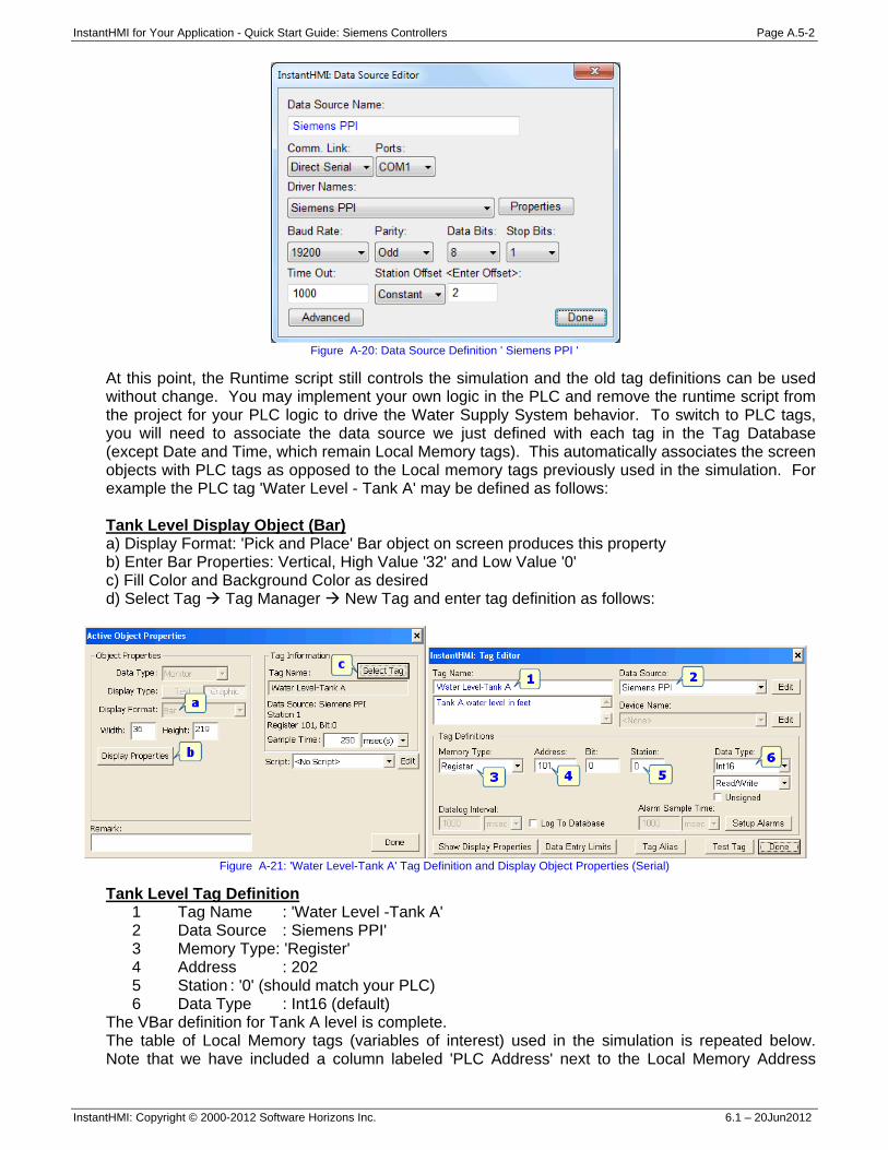
InstantHMI for Your Application - Quick Start Guide: Siemens Controllers Page A.5-2
InstantHMI: Copyright © 2000-2012 Software Horizons Inc. 6.1 – 20Jun2012
Figure A-20: Data Source Definition ' Siemens PPI '
At this point, the Runtime script still controls the simulation and the old tag definitions can be used without change. You may implement your own logic in the PLC and remove the runtime script from the project for your PLC logic to drive the Water Supply System behavior. To switch to PLC tags, you will need to associate the data source we just defined with each tag in the Tag Database (except Date and Time, which remain Local Memory tags). This automatically associates the screen objects with PLC tags as opposed to the Local memory tags previously used in the simulation. For example the PLC tag 'Water Level - Tank A' may be defined as follows: Tank Level Display Object (Bar) a) Display Format: 'Pick and Place' Bar object on screen produces this property b) Enter Bar Properties: Vertical, High Value '32' and Low Value '0' c) Fill Color and Background Color as desired d) Select Tag Tag Manager New Tag and enter tag definition as follows:
Figure A-21: 'Water Level-Tank A' Tag Definition and Display Object Properties (Serial)
Tank Level Tag Definition 1 Tag Name : 'Water Level -Tank A' 2 Data Source : Siemens PPI' 3 Memory Type: 'Register' 4 Address : 202 5 Station : '0' (should match your PLC) 6 Data Type : Int16 (default)
The VBar definition for Tank A level is complete. The table of Local Memory tags (variables of interest) used in the simulation is repeated below. Note that we have included a column labeled 'PLC Address' next to the Local Memory Address
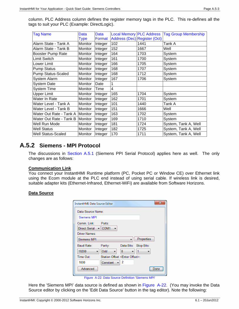
InstantHMI for Your Application - Quick Start Guide: Siemens Controllers Page A.5-3
InstantHMI: Copyright © 2000-2012 Software Horizons Inc. 6.1 – 20Jun2012
column. PLC Address column defines the register memory tags in the PLC. This re-defines all the tags to suit your PLC (Example: DirectLogic).
Tag Name Data Type
Data Format
Local Memory Address (Dec)
PLC Address Register (Oct)
Tag Group Membership
Alarm State - Tank A Monitor Integer 102 1441 Tank A Alarm State - Tank B Monitor Integer 152 1667 Well Booster Pump Rate Monitor Integer 164 1703 System Limit Switch Monitor Integer 161 1700 System Lower Limit Monitor Integer 166 1705 System Pump Status Monitor Integer 168 1707 System Pump Status-Scaled Monitor Integer 168 1712 System System Alarm Monitor Integer 167 1706 System System Date Monitor Date 1 System Time Monitor Time 4 Upper Limit Monitor Integer 165 1704 System Water In Rate Monitor Integer 162 1701 System Water Level - Tank A Monitor Integer 101 1440 Tank A Water Level - Tank B Monitor Integer 151 1666 Well Water Out Rate - Tank A Monitor Integer 163 1702 System Water Out Rate - Tank B Monitor Integer 169 1710 System Well Run Mode Monitor Integer 181 1724 System, Tank A, Well Well Status Monitor Integer 182 1725 System, Tank A, Well Well Status-Scaled Monitor Integer 170 1711 System, Tank A, Well
A.5.2 Siemens - MPI Protocol
The discussions in Section A.5.1 (Siemens PPI Serial Protocol) applies here as well. The only changes are as follows: Communication Link You connect your InstantHMI Runtime platform (PC, Pocket PC or Window CE) over Ethernet link using the Ecom module at the PLC end instead of using serial cable. If wireless link is desired, suitable adapter kits (Ethernet-Infrared, Ethernet-WiFi) are available from Software Horizons. Data Source
Figure A-22: Data Source Definition 'Siemens MPI'
Here the 'Siemens MPI’ data source is defined as shown in Figure A-22. (You may invoke the Data Source editor by clicking on the 'Edit Data Source' button in the tag editor). Note the following:
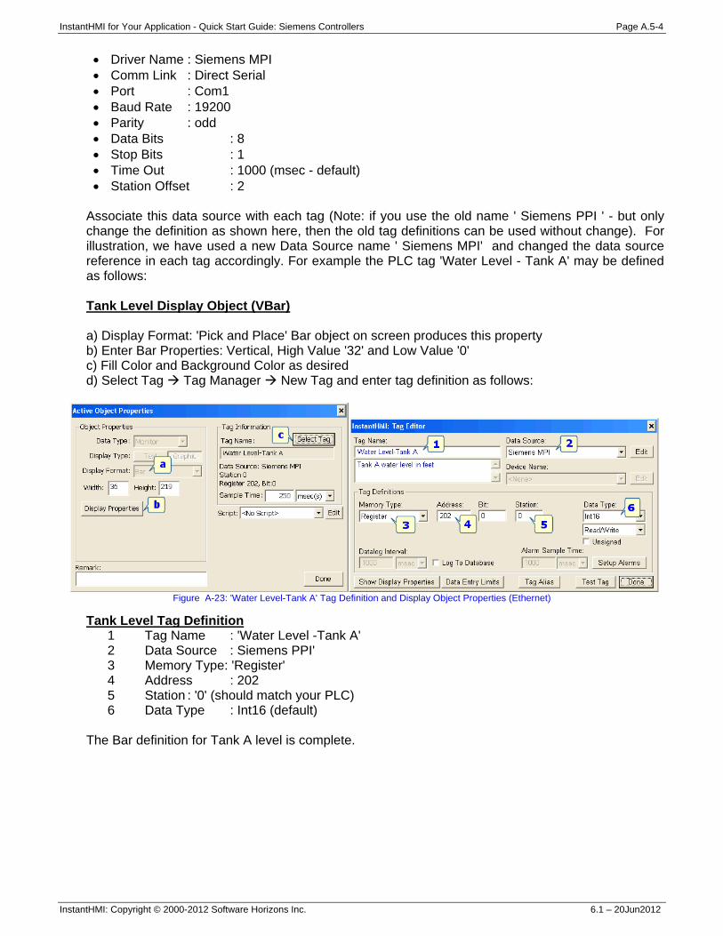
InstantHMI for Your Application - Quick Start Guide: Siemens Controllers Page A.5-4
InstantHMI: Copyright © 2000-2012 Software Horizons Inc. 6.1 – 20Jun2012
• Driver Name : Siemens MPI • Comm Link : Direct Serial • Port : Com1 • Baud Rate : 19200 • Parity : odd • Data Bits : 8 • Stop Bits : 1 • Time Out : 1000 (msec - default) • Station Offset : 2
Associate this data source with each tag (Note: if you use the old name ' Siemens PPI ' - but only change the definition as shown here, then the old tag definitions can be used without change). For illustration, we have used a new Data Source name ' Siemens MPI' and changed the data source reference in each tag accordingly. For example the PLC tag 'Water Level - Tank A' may be defined as follows: Tank Level Display Object (VBar) a) Display Format: 'Pick and Place' Bar object on screen produces this property b) Enter Bar Properties: Vertical, High Value '32' and Low Value '0' c) Fill Color and Background Color as desired d) Select Tag Tag Manager New Tag and enter tag definition as follows:
Figure A-23: 'Water Level-Tank A' Tag Definition and Display Object Properties (Ethernet)
Tank Level Tag Definition 1 Tag Name : 'Water Level -Tank A' 2 Data Source : Siemens PPI' 3 Memory Type: 'Register' 4 Address : 202 5 Station : '0' (should match your PLC) 6 Data Type : Int16 (default)
The Bar definition for Tank A level is complete.
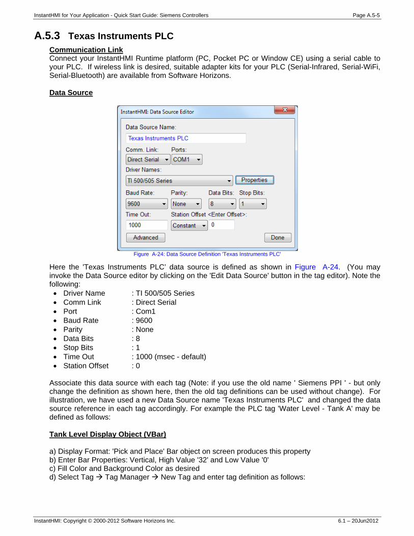
InstantHMI for Your Application - Quick Start Guide: Siemens Controllers Page A.5-5
InstantHMI: Copyright © 2000-2012 Software Horizons Inc. 6.1 – 20Jun2012
A.5.3 Texas Instruments PLC Communication Link Connect your InstantHMI Runtime platform (PC, Pocket PC or Window CE) using a serial cable to your PLC. If wireless link is desired, suitable adapter kits for your PLC (Serial-Infrared, Serial-WiFi, Serial-Bluetooth) are available from Software Horizons. Data Source
Figure A-24: Data Source Definition 'Texas Instruments PLC'
Here the 'Texas Instruments PLC’ data source is defined as shown in Figure A-24. (You may invoke the Data Source editor by clicking on the 'Edit Data Source' button in the tag editor). Note the following: • Driver Name : TI 500/505 Series • Comm Link : Direct Serial • Port : Com1 • Baud Rate : 9600 • Parity : None • Data Bits : 8 • Stop Bits : 1 • Time Out : 1000 (msec - default) • Station Offset : 0
Associate this data source with each tag (Note: if you use the old name ' Siemens PPI ' - but only change the definition as shown here, then the old tag definitions can be used without change). For illustration, we have used a new Data Source name 'Texas Instruments PLC' and changed the data source reference in each tag accordingly. For example the PLC tag 'Water Level - Tank A' may be defined as follows: Tank Level Display Object (VBar) a) Display Format: 'Pick and Place' Bar object on screen produces this property b) Enter Bar Properties: Vertical, High Value '32' and Low Value '0' c) Fill Color and Background Color as desired d) Select Tag Tag Manager New Tag and enter tag definition as follows:
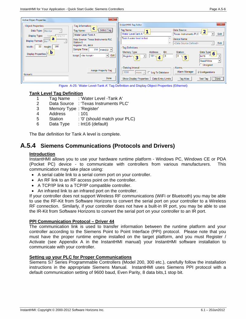
InstantHMI for Your Application - Quick Start Guide: Siemens Controllers Page A.5-6
InstantHMI: Copyright © 2000-2012 Software Horizons Inc. 6.1 – 20Jun2012
Figure A-25: 'Water Level-Tank A' Tag Definition and Display Object Properties (Ethernet)
Tank Level Tag Definition 1 Tag Name : 'Water Level -Tank A' 2 Data Source : ‘Texas Instruments PLC' 3 Memory Type : 'Register' 4 Address : 101 5 Station : '0' (should match your PLC) 6 Data Type : Int16 (default)
The Bar definition for Tank A level is complete.
A.5.4 Siemens Communications (Protocols and Drivers) Introduction InstantHMI allows you to use your hardware runtime platform - Windows PC, Windows CE or PDA (Pocket PC) device - to communicate with controllers from various manufacturers. This communication may take place using: • A serial cable link to a serial comm port on your controller. • An RF link to an RF access point on the controller. • A TCP/IP link to a TCP/IP compatible controller. • An infrared link to an infrared port on the controller.
If your controller does not support Wireless RF communications (WiFi or Bluetooth) you may be able to use the RF-Kit from Software Horizons to convert the serial port on your controller to a Wireless RF connection. Similarly, if your controller does not have a built-in IR port, you may be able to use the IR-Kit from Software Horizons to convert the serial port on your controller to an IR port. PPI Communication Protocol – Driver 44 The communication link is used to transfer information between the runtime platform and your controller according to the Siemens Point to Point Interface (PPI) protocol. Please note that you must have the proper runtime engine installed on the target platform, and you must Register / Activate (see Appendix A in the InstantHMI manual) your InstantHMI software installation to communicate with your controller. Setting up your PLC for Proper Communications Siemens S7 Series Programmable Controllers (Model 200, 300 etc.), carefully follow the installation instructions in the appropriate Siemens Manual. InstantHMI uses Siemens PPI protocol with a default communication setting of 9600 baud, Even Parity, 8 data bits,1 stop bit.
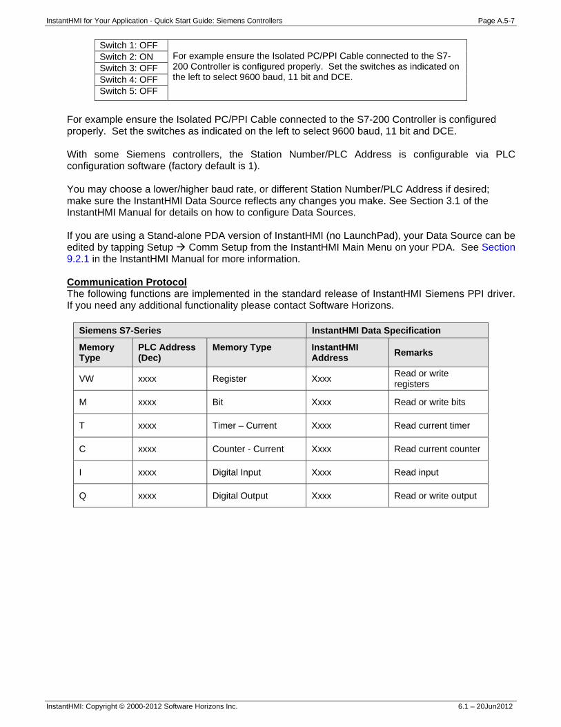
InstantHMI for Your Application - Quick Start Guide: Siemens Controllers Page A.5-7
InstantHMI: Copyright © 2000-2012 Software Horizons Inc. 6.1 – 20Jun2012
Switch 1: OFF For example ensure the Isolated PC/PPI Cable connected to the S7-200 Controller is configured properly. Set the switches as indicated on the left to select 9600 baud, 11 bit and DCE.
Switch 2: ON Switch 3: OFF Switch 4: OFF Switch 5: OFF
For example ensure the Isolated PC/PPI Cable connected to the S7-200 Controller is configured properly. Set the switches as indicated on the left to select 9600 baud, 11 bit and DCE. With some Siemens controllers, the Station Number/PLC Address is configurable via PLC configuration software (factory default is 1). You may choose a lower/higher baud rate, or different Station Number/PLC Address if desired; make sure the InstantHMI Data Source reflects any changes you make. See Section 3.1 of the InstantHMI Manual for details on how to configure Data Sources. If you are using a Stand-alone PDA version of InstantHMI (no LaunchPad), your Data Source can be edited by tapping Setup Comm Setup from the InstantHMI Main Menu on your PDA. See Section 9.2.1 in the InstantHMI Manual for more information. Communication Protocol The following functions are implemented in the standard release of InstantHMI Siemens PPI driver. If you need any additional functionality please contact Software Horizons.
Siemens S7-Series InstantHMI Data Specification
Memory Type
PLC Address (Dec)
Memory Type
InstantHMI Address Remarks
VW xxxx Register Xxxx Read or write registers
M xxxx Bit Xxxx Read or write bits
T xxxx Timer – Current Xxxx Read current timer
C xxxx Counter - Current Xxxx Read current counter
I xxxx Digital Input Xxxx Read input
Q xxxx Digital Output Xxxx Read or write output
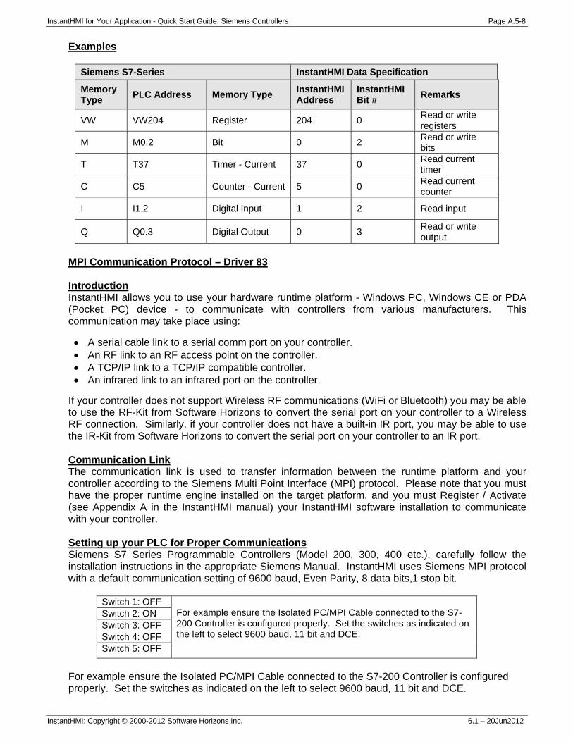
InstantHMI for Your Application - Quick Start Guide: Siemens Controllers Page A.5-8
InstantHMI: Copyright © 2000-2012 Software Horizons Inc. 6.1 – 20Jun2012
Examples
Siemens S7-Series InstantHMI Data Specification
Memory Type PLC Address Memory Type InstantHMI
Address InstantHMI Bit # Remarks
VW VW204 Register 204 0 Read or write registers
M M0.2 Bit 0 2 Read or write bits
T T37 Timer - Current 37 0 Read current timer
C C5 Counter - Current 5 0 Read current counter
I I1.2 Digital Input 1 2 Read input
Q Q0.3 Digital Output 0 3 Read or write output
MPI Communication Protocol – Driver 83 Introduction InstantHMI allows you to use your hardware runtime platform - Windows PC, Windows CE or PDA (Pocket PC) device - to communicate with controllers from various manufacturers. This communication may take place using: • A serial cable link to a serial comm port on your controller. • An RF link to an RF access point on the controller. • A TCP/IP link to a TCP/IP compatible controller. • An infrared link to an infrared port on the controller.
If your controller does not support Wireless RF communications (WiFi or Bluetooth) you may be able to use the RF-Kit from Software Horizons to convert the serial port on your controller to a Wireless RF connection. Similarly, if your controller does not have a built-in IR port, you may be able to use the IR-Kit from Software Horizons to convert the serial port on your controller to an IR port. Communication Link The communication link is used to transfer information between the runtime platform and your controller according to the Siemens Multi Point Interface (MPI) protocol. Please note that you must have the proper runtime engine installed on the target platform, and you must Register / Activate (see Appendix A in the InstantHMI manual) your InstantHMI software installation to communicate with your controller. Setting up your PLC for Proper Communications Siemens S7 Series Programmable Controllers (Model 200, 300, 400 etc.), carefully follow the installation instructions in the appropriate Siemens Manual. InstantHMI uses Siemens MPI protocol with a default communication setting of 9600 baud, Even Parity, 8 data bits,1 stop bit.
Switch 1: OFF For example ensure the Isolated PC/MPI Cable connected to the S7-200 Controller is configured properly. Set the switches as indicated on the left to select 9600 baud, 11 bit and DCE.
Switch 2: ON Switch 3: OFF Switch 4: OFF Switch 5: OFF
For example ensure the Isolated PC/MPI Cable connected to the S7-200 Controller is configured properly. Set the switches as indicated on the left to select 9600 baud, 11 bit and DCE.
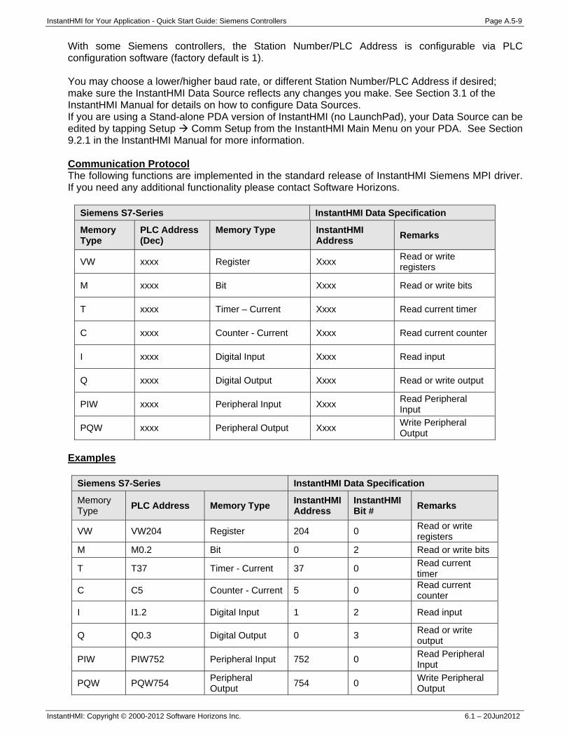
InstantHMI for Your Application - Quick Start Guide: Siemens Controllers Page A.5-9
InstantHMI: Copyright © 2000-2012 Software Horizons Inc. 6.1 – 20Jun2012
With some Siemens controllers, the Station Number/PLC Address is configurable via PLC configuration software (factory default is 1). You may choose a lower/higher baud rate, or different Station Number/PLC Address if desired; make sure the InstantHMI Data Source reflects any changes you make. See Section 3.1 of the InstantHMI Manual for details on how to configure Data Sources. If you are using a Stand-alone PDA version of InstantHMI (no LaunchPad), your Data Source can be edited by tapping Setup Comm Setup from the InstantHMI Main Menu on your PDA. See Section 9.2.1 in the InstantHMI Manual for more information. Communication Protocol The following functions are implemented in the standard release of InstantHMI Siemens MPI driver. If you need any additional functionality please contact Software Horizons.
Siemens S7-Series InstantHMI Data Specification
Memory Type
PLC Address (Dec)
Memory Type
InstantHMI Address Remarks
VW xxxx Register Xxxx Read or write registers
M xxxx Bit Xxxx Read or write bits
T xxxx Timer – Current Xxxx Read current timer
C xxxx Counter - Current Xxxx Read current counter
I xxxx Digital Input Xxxx Read input
Q xxxx Digital Output Xxxx Read or write output
PIW xxxx Peripheral Input Xxxx Read Peripheral Input
PQW xxxx Peripheral Output Xxxx Write Peripheral Output
Examples
Siemens S7-Series InstantHMI Data Specification
Memory Type PLC Address Memory Type InstantHMI
Address InstantHMI Bit # Remarks
VW VW204 Register 204 0 Read or write registers
M M0.2 Bit 0 2 Read or write bits
T T37 Timer - Current 37 0 Read current timer
C C5 Counter - Current 5 0 Read current counter
I I1.2 Digital Input 1 2 Read input
Q Q0.3 Digital Output 0 3 Read or write output
PIW PIW752 Peripheral Input 752 0 Read Peripheral Input
PQW PQW754 Peripheral Output 754 0 Write Peripheral
Output
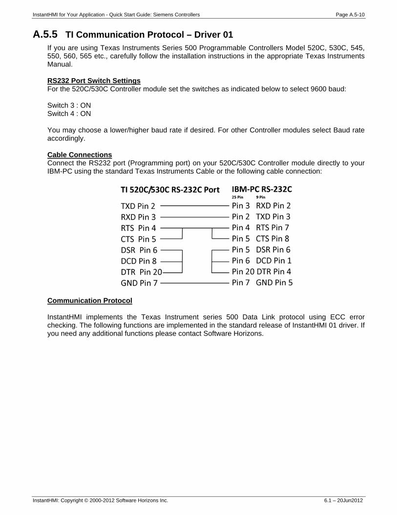
InstantHMI for Your Application - Quick Start Guide: Siemens Controllers Page A.5-10
InstantHMI: Copyright © 2000-2012 Software Horizons Inc. 6.1 – 20Jun2012
A.5.5 TI Communication Protocol – Driver 01 If you are using Texas Instruments Series 500 Programmable Controllers Model 520C, 530C, 545, 550, 560, 565 etc., carefully follow the installation instructions in the appropriate Texas Instruments Manual. RS232 Port Switch Settings For the 520C/530C Controller module set the switches as indicated below to select 9600 baud: Switch 3 : ON Switch 4 : ON You may choose a lower/higher baud rate if desired. For other Controller modules select Baud rate accordingly. Cable Connections Connect the RS232 port (Programming port) on your 520C/530C Controller module directly to your IBM-PC using the standard Texas Instruments Cable or the following cable connection:
Communication Protocol InstantHMI implements the Texas Instrument series 500 Data Link protocol using ECC error checking. The following functions are implemented in the standard release of InstantHMI 01 driver. If you need any additional functions please contact Software Horizons.
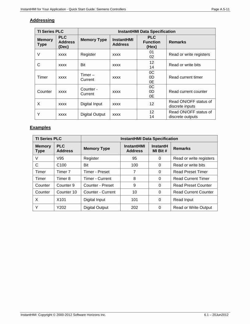
InstantHMI for Your Application - Quick Start Guide: Siemens Controllers Page A.5-11
InstantHMI: Copyright © 2000-2012 Software Horizons Inc. 6.1 – 20Jun2012
Addressing
TI Series PLC InstantHMI Data Specification
Memory Type
PLC Address (Dec)
Memory Type
InstantHMI Address
PLC Function
(Hex) Remarks
V xxxx Register xxxx 01 02 Read or write registers
C xxxx Bit xxxx 12 14 Read or write bits
Timer xxxx Timer – Current xxxx
0C 0D 0E
Read current timer
Counter xxxx Counter - Current xxxx
0C 0D 0E
Read current counter
X xxxx Digital Input xxxx 12 Read ON/OFF status of discrete inputs
Y xxxx Digital Output xxxx 12 14
Read ON/OFF status of discrete outputs
Examples
TI Series PLC InstantHMI Data Specification
Memory Type
PLC Address Memory Type InstantHMI
Address InstantHMI Bit # Remarks
V V95 Register 95 0 Read or write registers C C100 Bit 100 0 Read or write bits Timer Timer 7 Timer - Preset 7 0 Read Preset Timer Timer Timer 8 Timer - Current 8 0 Read Current Timer Counter Counter 9 Counter - Preset 9 0 Read Preset Counter Counter Counter 10 Counter - Current 10 0 Read Current Counter
X X101 Digital Input 101 0 Read Input
Y Y202 Digital Output 202 0 Read or Write Output

InstantHMI for Your Application - Quick Start Guide: Mitsubishi Controllers Page A.6-1
InstantHMI: Copyright © 2000-2012 Software Horizons Inc. 6.1 – 20Jun2012
A.6 Solution for Mitsubishi Controllers For training purposes, to explain the design of screens and screen objects independent of the PLC, initially we avoided the use of the PLC and used a 'Simulation Approach' (Runtime script and Local Memory in the runtime platform to simulate the control logic normally programmed in the PLC). This Simulation Approach did not require us to define a Data Source for the Local Memory in the PC Simulation of the PLC; nor did we need to worry about the Communication Link between the Runtime Platform and the PLC. However, to use data registers and I/O from Mitsubishi PLC (connected by Serial or Ethernet link to PC InstantHMI Runtime Engine) you must define a Data Source for your PLC. This Appendix may be used for any Mitsubishi controllers. Please refer to Memory Map for Mitsubishi PLC (Section A.6.2) if you wish to implement the Water Supply System control logic in your PLC and define PLC tags.
A.6.1 Mitsubishi Serial Protocol Communication Link Connect your InstantHMI Runtime platform (PC, Pocket PC or Window CE) using a serial cable to your PLC. If wireless link is desired, suitable adapter kits for your PLC (Serial-Infrared, Serial-WiFi, Serial-Bluetooth) are available from Software Horizons. Data Source Define the Data Source 'Mitsubishi' as shown in Figure A-26. (You may invoke the Data Source editor by clicking on the 'Edit Data Source' button in the tag editor). Note the various parameters in the Data Source definition: • Driver Name: Mitsubishi • Comm Link: Direct Serial • Port: Com1 • Baud Rate: 9600 • Parity: None • Data Bits: 8 • Stop Bits: 1 • Time Out: 1000 (msec - default) • Station Offset: 0
We have chosen Station Offset: 0 to match the PLC in our setup. Other driver options may be chosen to suit your own controller. The Mitsubishi driver supports the dedicated computer link protocols 1 to 4 with and without sum check and supports the programming port protocol for FX and FX2N controllers. Click the 'Properties' button to select the appropriate protocol settings for your controller. If your controller is connected through a computer link port select the protocol 'Computer Link' and select the format and sum check settings to match your controller as shown below.
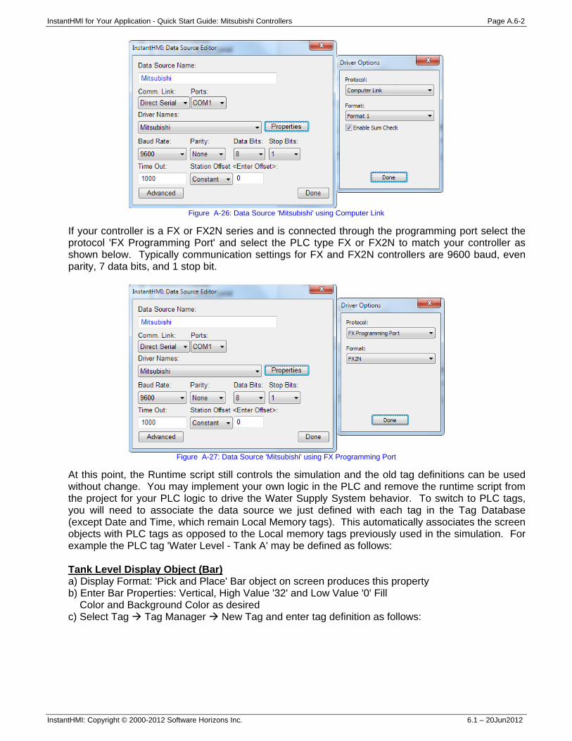
InstantHMI for Your Application - Quick Start Guide: Mitsubishi Controllers Page A.6-2
InstantHMI: Copyright © 2000-2012 Software Horizons Inc. 6.1 – 20Jun2012
Figure A-26: Data Source 'Mitsubishi' using Computer Link
If your controller is a FX or FX2N series and is connected through the programming port select the protocol 'FX Programming Port' and select the PLC type FX or FX2N to match your controller as shown below. Typically communication settings for FX and FX2N controllers are 9600 baud, even parity, 7 data bits, and 1 stop bit.
Figure A-27: Data Source 'Mitsubishi' using FX Programming Port
At this point, the Runtime script still controls the simulation and the old tag definitions can be used without change. You may implement your own logic in the PLC and remove the runtime script from the project for your PLC logic to drive the Water Supply System behavior. To switch to PLC tags, you will need to associate the data source we just defined with each tag in the Tag Database (except Date and Time, which remain Local Memory tags). This automatically associates the screen objects with PLC tags as opposed to the Local memory tags previously used in the simulation. For example the PLC tag 'Water Level - Tank A' may be defined as follows: Tank Level Display Object (Bar) a) Display Format: 'Pick and Place' Bar object on screen produces this property b) Enter Bar Properties: Vertical, High Value '32' and Low Value '0' Fill Color and Background Color as desired c) Select Tag Tag Manager New Tag and enter tag definition as follows:
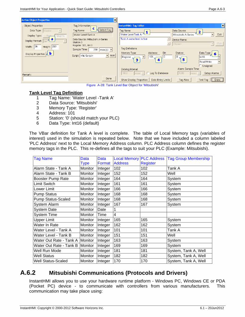
InstantHMI for Your Application - Quick Start Guide: Mitsubishi Controllers Page A.6-3
InstantHMI: Copyright © 2000-2012 Software Horizons Inc. 6.1 – 20Jun2012
Figure A-28: Tank Level Bar Object for 'Mitsubishi'
Tank Level Tag Definition 1 Tag Name: 'Water Level -Tank A' 2 Data Source: 'Mitsubishi' 3 Memory Type: 'Register' 4 Address: 101 5 Station: '0' (should match your PLC) 6 Data Type: Int16 (default)
The VBar definition for Tank A level is complete. The table of Local Memory tags (variables of interest) used in the simulation is repeated below. Note that we have included a column labeled 'PLC Address' next to the Local Memory Address column. PLC Address column defines the register memory tags in the PLC. This re-defines all the tags to suit your PLC (Example: Mitsubishi).
Tag Name Data Type
Data Format
Local Memory Address
PLC Address Register
Tag Group Membership
Alarm State - Tank A Monitor Integer 102 102 Tank A Alarm State - Tank B Monitor Integer 152 152 Well Booster Pump Rate Monitor Integer 164 164 System Limit Switch Monitor Integer 161 161 System Lower Limit Monitor Integer 166 166 System Pump Status Monitor Integer 168 168 System Pump Status-Scaled Monitor Integer 168 168 System System Alarm Monitor Integer 167 167 System System Date Monitor Date 1 System Time Monitor Time 4 Upper Limit Monitor Integer 165 165 System Water In Rate Monitor Integer 162 162 System Water Level - Tank A Monitor Integer 101 101 Tank A Water Level - Tank B Monitor Integer 151 151 Well Water Out Rate - Tank A Monitor Integer 163 163 System Water Out Rate - Tank B Monitor Integer 169 169 System Well Run Mode Monitor Integer 181 181 System, Tank A, Well Well Status Monitor Integer 182 182 System, Tank A, Well Well Status-Scaled Monitor Integer 170 170 System, Tank A, Well
A.6.2 Mitsubishi Communications (Protocols and Drivers)
InstantHMI allows you to use your hardware runtime platform - Windows PC, Windows CE or PDA (Pocket PC) device - to communicate with controllers from various manufacturers. This communication may take place using:
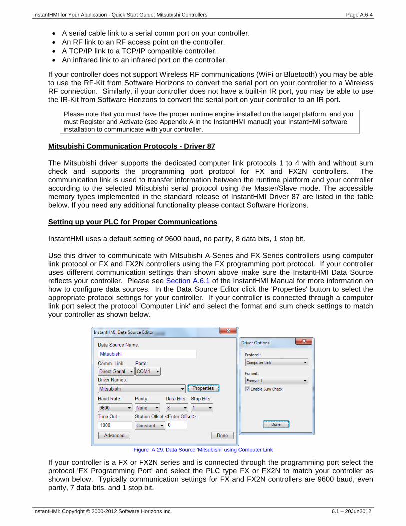
InstantHMI for Your Application - Quick Start Guide: Mitsubishi Controllers Page A.6-4
InstantHMI: Copyright © 2000-2012 Software Horizons Inc. 6.1 – 20Jun2012
• A serial cable link to a serial comm port on your controller. • An RF link to an RF access point on the controller. • A TCP/IP link to a TCP/IP compatible controller. • An infrared link to an infrared port on the controller.
If your controller does not support Wireless RF communications (WiFi or Bluetooth) you may be able to use the RF-Kit from Software Horizons to convert the serial port on your controller to a Wireless RF connection. Similarly, if your controller does not have a built-in IR port, you may be able to use the IR-Kit from Software Horizons to convert the serial port on your controller to an IR port.
Please note that you must have the proper runtime engine installed on the target platform, and you must Register and Activate (see Appendix A in the InstantHMI manual) your InstantHMI software installation to communicate with your controller.
Mitsubishi Communication Protocols - Driver 87 The Mitsubishi driver supports the dedicated computer link protocols 1 to 4 with and without sum check and supports the programming port protocol for FX and FX2N controllers. The communication link is used to transfer information between the runtime platform and your controller according to the selected Mitsubishi serial protocol using the Master/Slave mode. The accessible memory types implemented in the standard release of InstantHMI Driver 87 are listed in the table below. If you need any additional functionality please contact Software Horizons. Setting up your PLC for Proper Communications InstantHMI uses a default setting of 9600 baud, no parity, 8 data bits, 1 stop bit. Use this driver to communicate with Mitsubishi A-Series and FX-Series controllers using computer link protocol or FX and FX2N controllers using the FX programming port protocol. If your controller uses different communication settings than shown above make sure the InstantHMI Data Source reflects your controller. Please see Section A.6.1 of the InstantHMI Manual for more information on how to configure data sources. In the Data Source Editor click the 'Properties' button to select the appropriate protocol settings for your controller. If your controller is connected through a computer link port select the protocol 'Computer Link' and select the format and sum check settings to match your controller as shown below.
Figure A-29: Data Source 'Mitsubishi' using Computer Link
If your controller is a FX or FX2N series and is connected through the programming port select the protocol 'FX Programming Port' and select the PLC type FX or FX2N to match your controller as shown below. Typically communication settings for FX and FX2N controllers are 9600 baud, even parity, 7 data bits, and 1 stop bit.
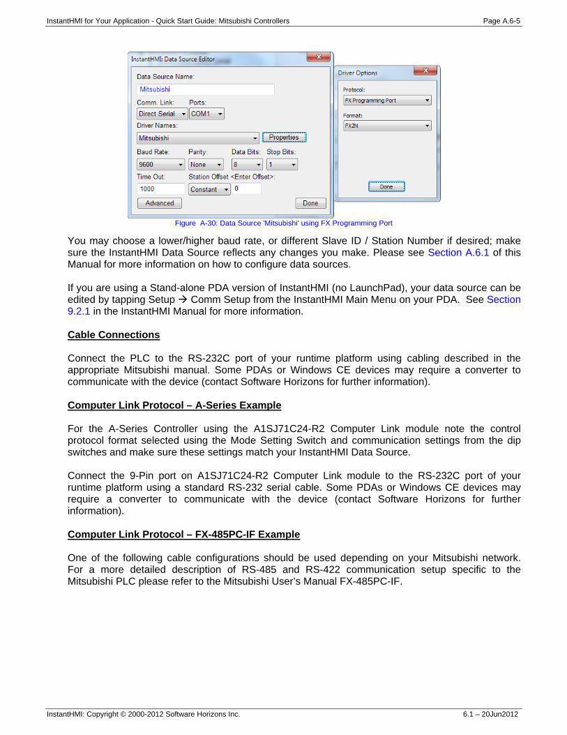
InstantHMI for Your Application - Quick Start Guide: Mitsubishi Controllers Page A.6-5
InstantHMI: Copyright © 2000-2012 Software Horizons Inc. 6.1 – 20Jun2012
Figure A-30: Data Source 'Mitsubishi' using FX Programming Port
You may choose a lower/higher baud rate, or different Slave ID / Station Number if desired; make sure the InstantHMI Data Source reflects any changes you make. Please see Section A.6.1 of this Manual for more information on how to configure data sources. If you are using a Stand-alone PDA version of InstantHMI (no LaunchPad), your data source can be edited by tapping Setup Comm Setup from the InstantHMI Main Menu on your PDA. See Section 9.2.1 in the InstantHMI Manual for more information. Cable Connections Connect the PLC to the RS-232C port of your runtime platform using cabling described in the appropriate Mitsubishi manual. Some PDAs or Windows CE devices may require a converter to communicate with the device (contact Software Horizons for further information). Computer Link Protocol – A-Series Example For the A-Series Controller using the A1SJ71C24-R2 Computer Link module note the control protocol format selected using the Mode Setting Switch and communication settings from the dip switches and make sure these settings match your InstantHMI Data Source. Connect the 9-Pin port on A1SJ71C24-R2 Computer Link module to the RS-232C port of your runtime platform using a standard RS-232 serial cable. Some PDAs or Windows CE devices may require a converter to communicate with the device (contact Software Horizons for further information). Computer Link Protocol – FX-485PC-IF Example One of the following cable configurations should be used depending on your Mitsubishi network. For a more detailed description of RS-485 and RS-422 communication setup specific to the Mitsubishi PLC please refer to the Mitsubishi User’s Manual FX-485PC-IF.
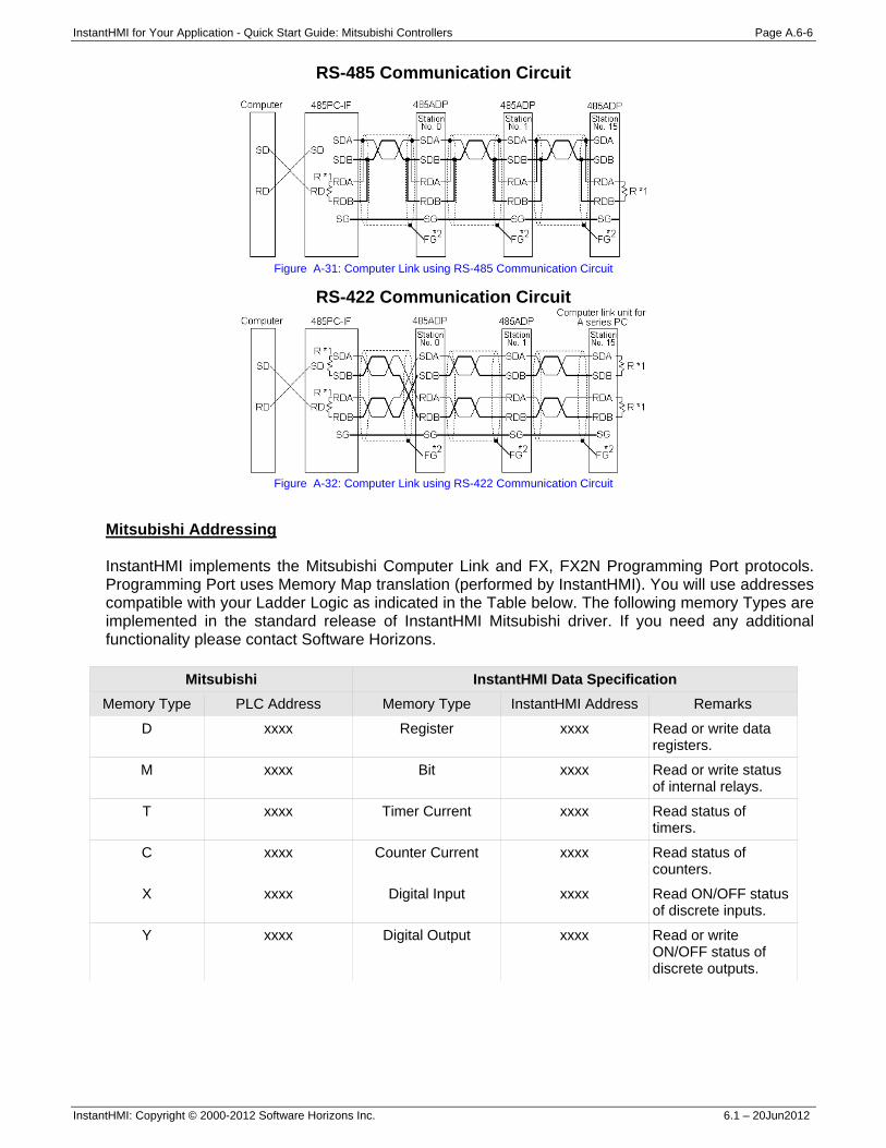
InstantHMI for Your Application - Quick Start Guide: Mitsubishi Controllers Page A.6-6
InstantHMI: Copyright © 2000-2012 Software Horizons Inc. 6.1 – 20Jun2012
RS-485 Communication Circuit
Figure A-31: Computer Link using RS-485 Communication Circuit
RS-422 Communication Circuit
Figure A-32: Computer Link using RS-422 Communication Circuit
Mitsubishi Addressing InstantHMI implements the Mitsubishi Computer Link and FX, FX2N Programming Port protocols. Programming Port uses Memory Map translation (performed by InstantHMI). You will use addresses compatible with your Ladder Logic as indicated in the Table below. The following memory Types are implemented in the standard release of InstantHMI Mitsubishi driver. If you need any additional functionality please contact Software Horizons.
Mitsubishi InstantHMI Data Specification Memory Type PLC Address Memory Type InstantHMI Address Remarks
D xxxx Register xxxx Read or write data registers.
M xxxx Bit xxxx Read or write status of internal relays.
T xxxx Timer Current xxxx Read status of timers.
C xxxx Counter Current xxxx Read status of counters.
X xxxx Digital Input xxxx Read ON/OFF status of discrete inputs.
Y xxxx Digital Output xxxx Read or write ON/OFF status of discrete outputs.
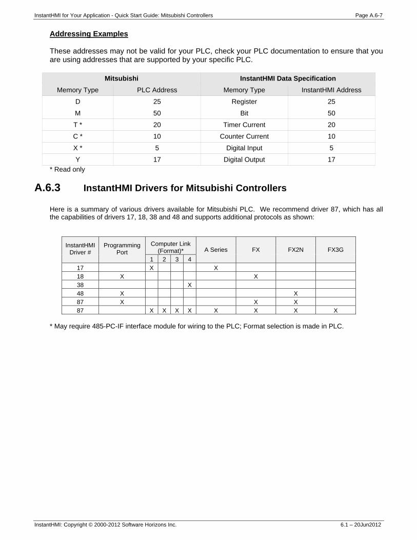
InstantHMI for Your Application - Quick Start Guide: Mitsubishi Controllers Page A.6-7
InstantHMI: Copyright © 2000-2012 Software Horizons Inc. 6.1 – 20Jun2012
Addressing Examples These addresses may not be valid for your PLC, check your PLC documentation to ensure that you are using addresses that are supported by your specific PLC.
Mitsubishi InstantHMI Data Specification Memory Type PLC Address Memory Type InstantHMI Address
D 25 Register 25
M 50 Bit 50
T * 20 Timer Current 20
C * 10 Counter Current 10
X * 5 Digital Input 5
Y 17 Digital Output 17 * Read only
A.6.3 InstantHMI Drivers for Mitsubishi Controllers
Here is a summary of various drivers available for Mitsubishi PLC. We recommend driver 87, which has all the capabilities of drivers 17, 18, 38 and 48 and supports additional protocols as shown:
InstantHMI Driver #
Programming Port
Computer Link (Format)*
A Series FX FX2N FX3G
1 2 3 4 17 X X 18 X X 38 X 48 X X 87 X X X 87 X X X X X X X X
* May require 485-PC-IF interface module for wiring to the PLC; Format selection is made in PLC.

InstantHMI for Your Application - Quick Start Guide: GPS Page A.7-1
InstantHMI: Copyright © 2000-2012 Software Horizons Inc. 6.1 – 20Jun2012
A.7 InstantHMI Designed for GPS Application A.7.1 Introduction to GPS
GPS became fully operational (after about 20 years of development and a system cost of $12 billion) on July 17, 1995. The GPS system in space consists of 6 orbital planes, each with 4 satellites in orbit at an altitude of 20,200km (12-hour orbit period), for a total of 24 satellites in the GPS Constellation. All satellites transmit at 1575.42MHz. Each satellite modulates using a unique 1023-bit pseudo-random (PRN) code sent at 1.023Mcps (chips per second). Measuring the time elapsed between the transmitted signal and received signal, helps determine receiver’s distance to the satellite. GPS system data are transmitted using modulated PRN code at 50bps. Ephemeris data is a table containing the predicted positions of artificial satellites orbiting the Earth. Each satellite has its own table that details its exact point in space and time. This data is essential for determining location via GPS. Typical GPS Receivers cost between $60 and $160. The interface is single or dual serial port. Protocols include NMEA-0183, Trimble (TSIP and TAIP), Garmin, etc.
A.7.2 GPS Serial Protocol (NMEA) NMEA-0183 (National Marine Electronics Association) is the protocol for navigation data exchange among marine electronics (GPS, LORAN, auto-pilot, etc) available on nearly every commercial GPS with a serial port. NMEA ASCII comma-delimited protocol string examples:
$GPGGA – GPS fix data message (latitude, longitude, time, # satellites, etc) $GPGGL – Geographic position (latitude, longitude, time) $GPGSA – GPS DOP (dilution of precision) and active satellites (# satellites, P/H/V DOP) $GPGSV – GPS satellites in view (satellite elevation/azimuth, SNR, etc) $GPVTG – GPS velocity and heading $GPZDA – Time & Date message
NMEA strings are followed by a precisely defined number of data fields. Not all of the above strings may be accessible in a specific receiver implementation. Communication Link InstantHMI allows you to use your hardware runtime platform - Windows PC, Windows CE or PDA (Pocket PC) device - to communicate with GPS receivers from various manufacturers. Due to inherent mobility of GPS receivers, the mobile PDA platforms will be the most appropriate. Some PDA manufacturers have integrated GPS receivers in the PDA. One such device (TDS Nomad) is available from Software Horizons with InstantHMI runtime pre-installed, pre-tested and 'ready to go'. In case of integrated (internal) GPS receivers no external communication link is necessary. If the GPS receiver is external to the InstantHMI platform, this communication may take place using: • A serial cable link to a serial comm port on your GPS receiver. • A Bluetooth RF link to your Bluetooth enabled GPS receiver.
Connect the GPS receiver to the RS-232C port of your runtime platform using a standard RS-232 Cable. Some PDAs or Windows CE devices may require a converter to communicate with the device (contact Software Horizons for further information). If your receiver does not support Wireless Bluetooth communications you may be able to use the RF-Kit from Software Horizons to convert the serial port on your controller to a Wireless RF connection.
Please note that you must have the proper runtime engine installed on the target platform, and you must Register and Activate (see Appendix A in the InstantHMI manual) your InstantHMI software installation to communicate with your controller.
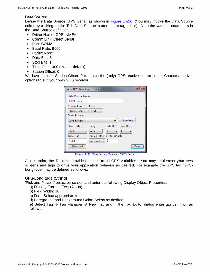
InstantHMI for Your Application - Quick Start Guide: GPS Page A.7-2
InstantHMI: Copyright © 2000-2012 Software Horizons Inc. 6.1 – 20Jun2012
Data Source Define the Data Source 'GPS Serial' as shown in Figure D-26. (You may invoke the Data Source editor by clicking on the 'Edit Data Source' button in the tag editor). Note the various parameters in the Data Source definition: • Driver Name: GPS NMEA • Comm Link: Direct Serial • Port: COM2 • Baud Rate: 9600 • Parity: None • Data Bits: 8 • Stop Bits: 1 • Time Out: 1000 (msec - default) • Station Offset: 0
We have chosen Station Offset: 0 to match the (only) GPS receiver in our setup. Choose all driver options to suit your own GPS receiver.
Figure A-33: Data Source Definition 'GPS-Serial'
At this point, the Runtime provides access to all GPS variables. You may implement your own screens and tags to drive your application behavior as desired. For example the GPS tag 'GPS-Longitude' may be defined as follows: GPS-Longitude (String) 'Pick and Place' # object on screen and enter the following Display Object Properties:
a) Display Format: Text (Alpha) b) Field Width: 16 c) Font: Select appropriate font d) Foreground and Background Color: Select as desired e) Select Tag Tag Manager New Tag and in the Tag Editor dialog enter tag definition as follows:
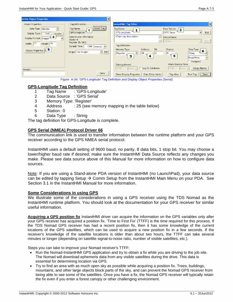
InstantHMI for Your Application - Quick Start Guide: GPS Page A.7-3
InstantHMI: Copyright © 2000-2012 Software Horizons Inc. 6.1 – 20Jun2012
Figure A-34: 'GPS-Longitude' Tag Definition and Display Object Properties (Serial)
GPS-Longitude Tag Definition 1 Tag Name : 'GPS-Longitude' 2 Data Source : 'GPS Serial' 3 Memory Type: 'Register' 4 Address : 25 (see memory mapping in the table below) 5 Station : 0 6 Data Type : String
The tag definition for GPS-Longitude is complete. GPS Serial (NMEA) Protocol Driver 66 The communication link is used to transfer information between the runtime platform and your GPS receiver according to the GPS NMEA serial protocol. InstantHMI uses a default setting of 9600 baud, no parity, 8 data bits, 1 stop bit. You may choose a lower/higher baud rate if desired; make sure the InstantHMI Data Source reflects any changes you make. Please see data source above of this Manual for more information on how to configure data sources. Note: If you are using a Stand-alone PDA version of InstantHMI (no LaunchPad), your data source can be edited by tapping Setup Comm Setup from the InstantHMI Main Menu on your PDA. See Section 3.1 in the InstantHMI Manual for more information. Some Considerations in using GPS We illustrate some of the considerations in using a GPS receiver using the TDS Nomad as the InstantHMI runtime platform. You should look at the documentation for your GPS receiver for similar useful information. Acquiring a GPS position fix InstantHMI driver can acquire the information on the GPS variables only after your GPS receiver has acquired a position fix. 'Time to First Fix' (TTFF) is the time required for this process. If the TDS Nomad GPS receiver has had a recent position fix, then it has some knowledge of the current locations of the GPS satellites, which can be used to acquire a new position fix in a few seconds. If the receiver's knowledge of the satellite locations is older than about two hours, the TTFF can take several minutes or longer (depending on satellite signal-to-noise ratio, number of visible satellites, etc.). Steps you can take to improve your Nomad receiver's TTFF: • Run the Nomad-InstantHMI GPS application and try to obtain a fix while you are driving to the job site.
The Nomad will download ephemeris data from any visible satellites during the drive. This data is essential for determining location via GPS.
• Try to find an area with as much open sky as possible while acquiring a position fix. Trees, buildings, mountains, and other large objects block parts of the sky, and can prevent the Nomad GPS receiver from being able to see some of the satellites. Once you have a fix, the Nomad GPS receiver will typically retain the fix even if you enter a forest canopy or other challenging environment.
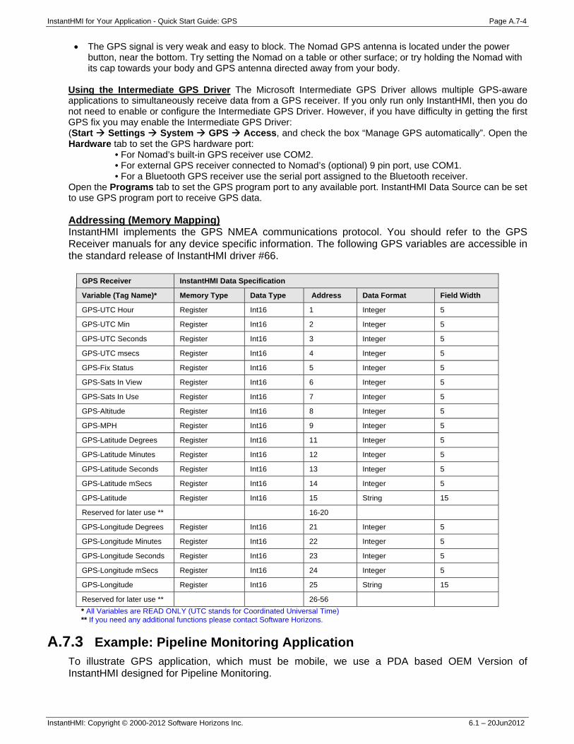
InstantHMI for Your Application - Quick Start Guide: GPS Page A.7-4
InstantHMI: Copyright © 2000-2012 Software Horizons Inc. 6.1 – 20Jun2012
• The GPS signal is very weak and easy to block. The Nomad GPS antenna is located under the power button, near the bottom. Try setting the Nomad on a table or other surface; or try holding the Nomad with its cap towards your body and GPS antenna directed away from your body.
Using the Intermediate GPS Driver The Microsoft Intermediate GPS Driver allows multiple GPS-aware applications to simultaneously receive data from a GPS receiver. If you only run only InstantHMI, then you do not need to enable or configure the Intermediate GPS Driver. However, if you have difficulty in getting the first GPS fix you may enable the Intermediate GPS Driver: (Start Settings System GPS Access, and check the box “Manage GPS automatically”. Open the Hardware tab to set the GPS hardware port:
• For Nomad’s built-in GPS receiver use COM2. • For external GPS receiver connected to Nomad’s (optional) 9 pin port, use COM1. • For a Bluetooth GPS receiver use the serial port assigned to the Bluetooth receiver.
Open the Programs tab to set the GPS program port to any available port. InstantHMI Data Source can be set to use GPS program port to receive GPS data. Addressing (Memory Mapping) InstantHMI implements the GPS NMEA communications protocol. You should refer to the GPS Receiver manuals for any device specific information. The following GPS variables are accessible in the standard release of InstantHMI driver #66.
GPS Receiver InstantHMI Data Specification
Variable (Tag Name)* Memory Type Data Type Address Data Format Field Width
GPS-UTC Hour Register Int16 1 Integer 5
GPS-UTC Min Register Int16 2 Integer 5
GPS-UTC Seconds Register Int16 3 Integer 5
GPS-UTC msecs Register Int16 4 Integer 5
GPS-Fix Status Register Int16 5 Integer 5
GPS-Sats In View Register Int16 6 Integer 5
GPS-Sats In Use Register Int16 7 Integer 5
GPS-Altitude Register Int16 8 Integer 5
GPS-MPH Register Int16 9 Integer 5
GPS-Latitude Degrees Register Int16 11 Integer 5
GPS-Latitude Minutes Register Int16 12 Integer 5
GPS-Latitude Seconds Register Int16 13 Integer 5
GPS-Latitude mSecs Register Int16 14 Integer 5
GPS-Latitude Register Int16 15 String 15
Reserved for later use ** 16-20
GPS-Longitude Degrees Register Int16 21 Integer 5
GPS-Longitude Minutes Register Int16 22 Integer 5
GPS-Longitude Seconds Register Int16 23 Integer 5
GPS-Longitude mSecs Register Int16 24 Integer 5
GPS-Longitude Register Int16 25 String 15
Reserved for later use ** 26-56 * All Variables are READ ONLY (UTC stands for Coordinated Universal Time) ** If you need any additional functions please contact Software Horizons.
A.7.3 Example: Pipeline Monitoring Application To illustrate GPS application, which must be mobile, we use a PDA based OEM Version of InstantHMI designed for Pipeline Monitoring.
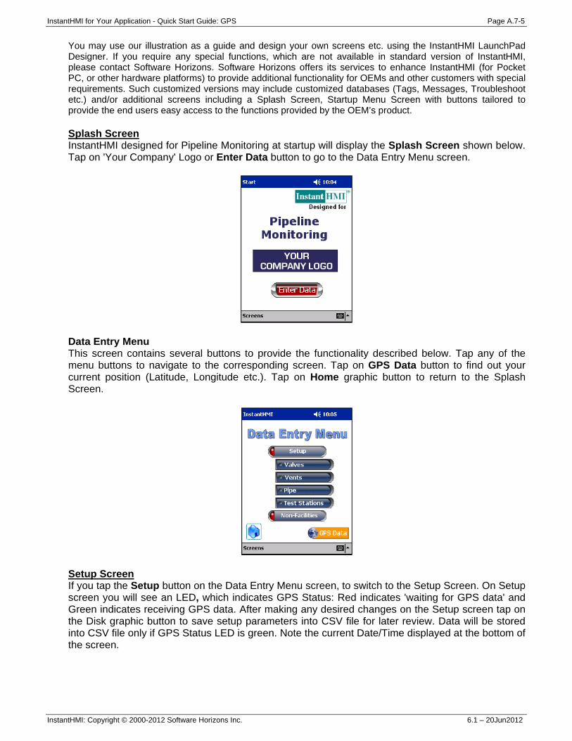
InstantHMI for Your Application - Quick Start Guide: GPS Page A.7-5
InstantHMI: Copyright © 2000-2012 Software Horizons Inc. 6.1 – 20Jun2012
You may use our illustration as a guide and design your own screens etc. using the InstantHMI LaunchPad Designer. If you require any special functions, which are not available in standard version of InstantHMI, please contact Software Horizons. Software Horizons offers its services to enhance InstantHMI (for Pocket PC, or other hardware platforms) to provide additional functionality for OEMs and other customers with special requirements. Such customized versions may include customized databases (Tags, Messages, Troubleshoot etc.) and/or additional screens including a Splash Screen, Startup Menu Screen with buttons tailored to provide the end users easy access to the functions provided by the OEM’s product. Splash Screen InstantHMI designed for Pipeline Monitoring at startup will display the Splash Screen shown below. Tap on 'Your Company' Logo or Enter Data button to go to the Data Entry Menu screen.
Data Entry Menu This screen contains several buttons to provide the functionality described below. Tap any of the menu buttons to navigate to the corresponding screen. Tap on GPS Data button to find out your current position (Latitude, Longitude etc.). Tap on Home graphic button to return to the Splash Screen.
Setup Screen If you tap the Setup button on the Data Entry Menu screen, to switch to the Setup Screen. On Setup screen you will see an LED, which indicates GPS Status: Red indicates 'waiting for GPS data' and Green indicates receiving GPS data. After making any desired changes on the Setup screen tap on the Disk graphic button to save setup parameters into CSV file for later review. Data will be stored into CSV file only if GPS Status LED is green. Note the current Date/Time displayed at the bottom of the screen.
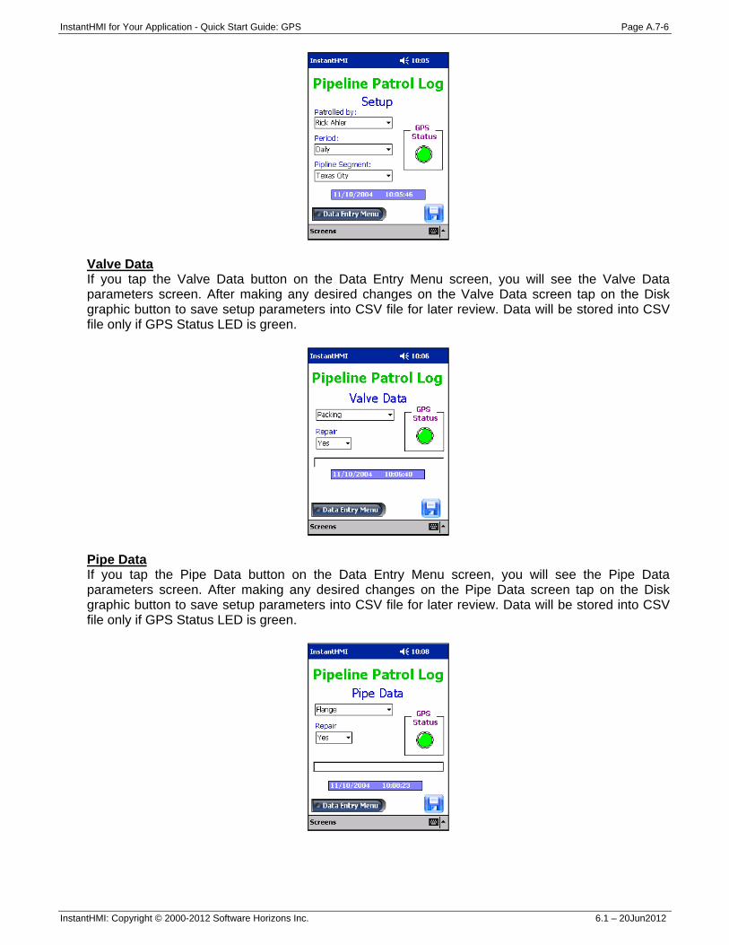
InstantHMI for Your Application - Quick Start Guide: GPS Page A.7-6
InstantHMI: Copyright © 2000-2012 Software Horizons Inc. 6.1 – 20Jun2012
Valve Data If you tap the Valve Data button on the Data Entry Menu screen, you will see the Valve Data parameters screen. After making any desired changes on the Valve Data screen tap on the Disk graphic button to save setup parameters into CSV file for later review. Data will be stored into CSV file only if GPS Status LED is green.
Pipe Data If you tap the Pipe Data button on the Data Entry Menu screen, you will see the Pipe Data parameters screen. After making any desired changes on the Pipe Data screen tap on the Disk graphic button to save setup parameters into CSV file for later review. Data will be stored into CSV file only if GPS Status LED is green.
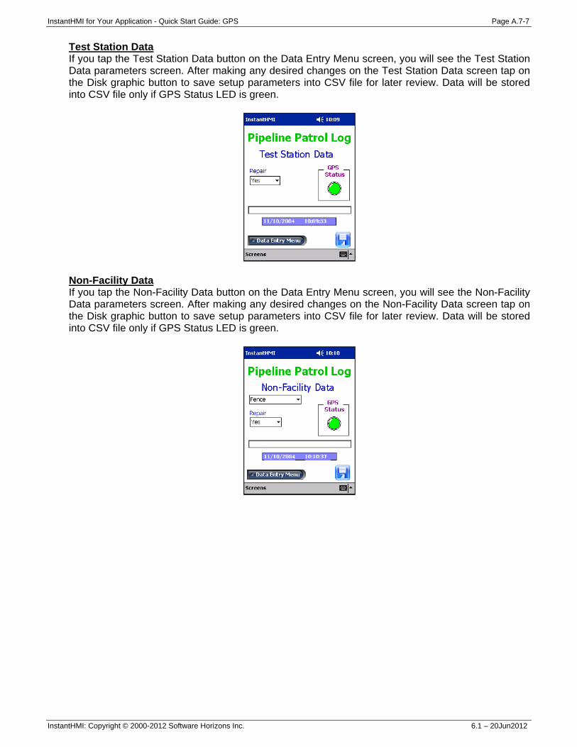
InstantHMI for Your Application - Quick Start Guide: GPS Page A.7-7
InstantHMI: Copyright © 2000-2012 Software Horizons Inc. 6.1 – 20Jun2012
Test Station Data If you tap the Test Station Data button on the Data Entry Menu screen, you will see the Test Station Data parameters screen. After making any desired changes on the Test Station Data screen tap on the Disk graphic button to save setup parameters into CSV file for later review. Data will be stored into CSV file only if GPS Status LED is green.
Non-Facility Data If you tap the Non-Facility Data button on the Data Entry Menu screen, you will see the Non-Facility Data parameters screen. After making any desired changes on the Non-Facility Data screen tap on the Disk graphic button to save setup parameters into CSV file for later review. Data will be stored into CSV file only if GPS Status LED is green.
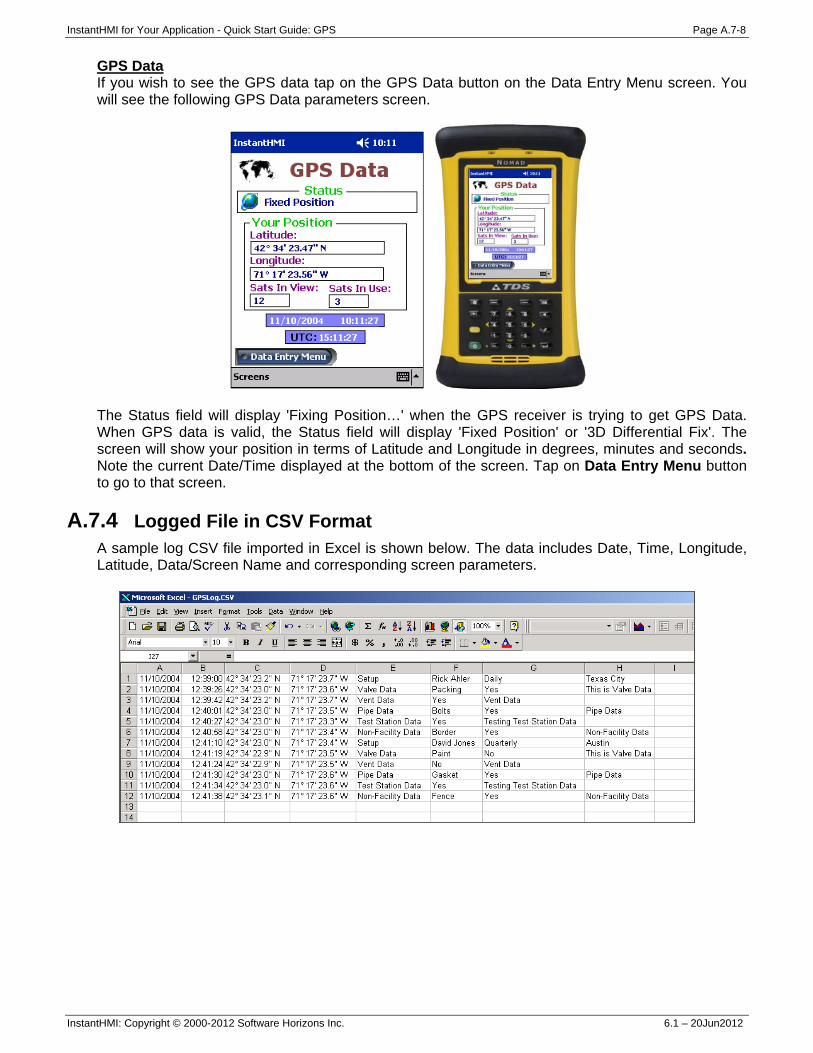
InstantHMI for Your Application - Quick Start Guide: GPS Page A.7-8
InstantHMI: Copyright © 2000-2012 Software Horizons Inc. 6.1 – 20Jun2012
GPS Data If you wish to see the GPS data tap on the GPS Data button on the Data Entry Menu screen. You will see the following GPS Data parameters screen.
The Status field will display 'Fixing Position…' when the GPS receiver is trying to get GPS Data. When GPS data is valid, the Status field will display 'Fixed Position' or '3D Differential Fix'. The screen will show your position in terms of Latitude and Longitude in degrees, minutes and seconds. Note the current Date/Time displayed at the bottom of the screen. Tap on Data Entry Menu button to go to that screen.
A.7.4 Logged File in CSV Format A sample log CSV file imported in Excel is shown below. The data includes Date, Time, Longitude, Latitude, Data/Screen Name and corresponding screen parameters.
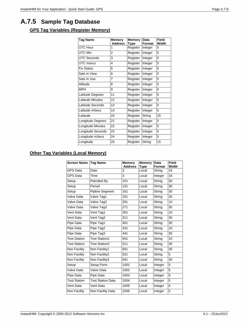
InstantHMI for Your Application - Quick Start Guide: GPS Page A.7-9
InstantHMI: Copyright © 2000-2012 Software Horizons Inc. 6.1 – 20Jun2012
A.7.5 Sample Tag Database GPS Tag Variables (Register Memory)
Tag Name Memory Address
Memory Type
Data Format
Field Width
UTC Hour 1 Register Integer 5 UTC Min 2 Register Integer 5 UTC Seconds 3 Register Integer 5 UTC msecs 4 Register Integer 5 Fix Status 5 Register Integer 5 Sats In View 6 Register Integer 5 Sats In Use 7 Register Integer 5 Altitude 8 Register Integer 5 MPH 9 Register Integer 5 Latitude Degrees 11 Register Integer 5 Latitude Minutes 12 Register Integer 5 Latitude Seconds 13 Register Integer 5 Latitude mSecs 14 Register Integer 5 Latitude 15 Register String 15 Longitude Degrees 21 Register Integer 5 Longitude Minutes 22 Register Integer 5 Longitude Seconds 23 Register Integer 5 Longitude mSecs 24 Register Integer 5 Longitude 25 Register String 15
Other Tag Variables (Local Memory)
Screen Name Tag Name Memory Address
Memory Type
Data Format
Field Width
GPS Data Date 2 Local String 16 GPS Data Time 3 Local Integer 16 Setup Patrolled By 101 Local String 30 Setup Period 131 Local String 30 Setup Pipline Segment 161 Local String 30 Valve Data Valve Tag1 231 Local String 30 Valve Data Valve Tag2 261 Local String 10 Valve Data Valve Tag3 271 Local String 30 Vent Data Vent Tag1 301 Local String 10 Vent Data Vent Tag2 311 Local String 30 Pipe Data Pipe Tag1 401 Local String 30 Pipe Data Pipe Tag2 431 Local String 10 Pipe Data Pipe Tag3 441 Local String 30 Test Station Test Station1 501 Local String 10 Test Station Test Station2 511 Local String 30 Non Facility Non Facility1 601 Local String 30 Non Facility Non Facility2 631 Local String 5 Non Facility Non Facility3 641 Local String 30 Setup Setup Form 1001 Local Integer 5 Valve Data Valve Data 1002 Local Integer 5 Pipe Data Pipe Data 1003 Local Integer 5 Test Station Test Station Data 1004 Local Integer 5 Vent Data Vent Data 1005 Local Integer 5 Non Facility Non Facility Data 1006 Local Integer 5

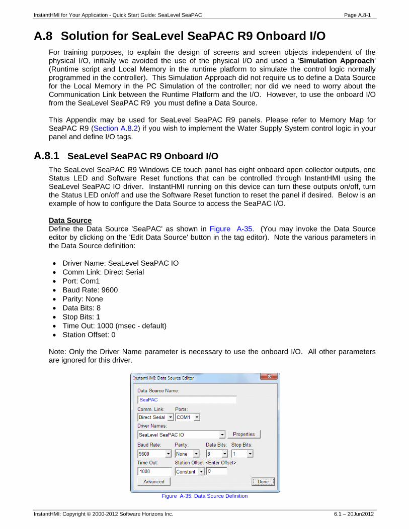
InstantHMI for Your Application - Quick Start Guide: SeaLevel SeaPAC Page A.8-1
InstantHMI: Copyright © 2000-2012 Software Horizons Inc. 6.1 – 20Jun2012
A.8 Solution for SeaLevel SeaPAC R9 Onboard I/O For training purposes, to explain the design of screens and screen objects independent of the physical I/O, initially we avoided the use of the physical I/O and used a 'Simulation Approach' (Runtime script and Local Memory in the runtime platform to simulate the control logic normally programmed in the controller). This Simulation Approach did not require us to define a Data Source for the Local Memory in the PC Simulation of the controller; nor did we need to worry about the Communication Link between the Runtime Platform and the I/O. However, to use the onboard I/O from the SeaLevel SeaPAC R9 you must define a Data Source. This Appendix may be used for SeaLevel SeaPAC R9 panels. Please refer to Memory Map for SeaPAC R9 (Section A.8.2) if you wish to implement the Water Supply System control logic in your panel and define I/O tags.
A.8.1 SeaLevel SeaPAC R9 Onboard I/O The SeaLevel SeaPAC R9 Windows CE touch panel has eight onboard open collector outputs, one Status LED and Software Reset functions that can be controlled through InstantHMI using the SeaLevel SeaPAC IO driver. InstantHMI running on this device can turn these outputs on/off, turn the Status LED on/off and use the Software Reset function to reset the panel if desired. Below is an example of how to configure the Data Source to access the SeaPAC I/O. Data Source Define the Data Source 'SeaPAC' as shown in Figure A-35. (You may invoke the Data Source editor by clicking on the 'Edit Data Source' button in the tag editor). Note the various parameters in the Data Source definition: • Driver Name: SeaLevel SeaPAC IO • Comm Link: Direct Serial • Port: Com1 • Baud Rate: 9600 • Parity: None • Data Bits: 8 • Stop Bits: 1 • Time Out: 1000 (msec - default) • Station Offset: 0
Note: Only the Driver Name parameter is necessary to use the onboard I/O. All other parameters are ignored for this driver.
Figure A-35: Data Source Definition
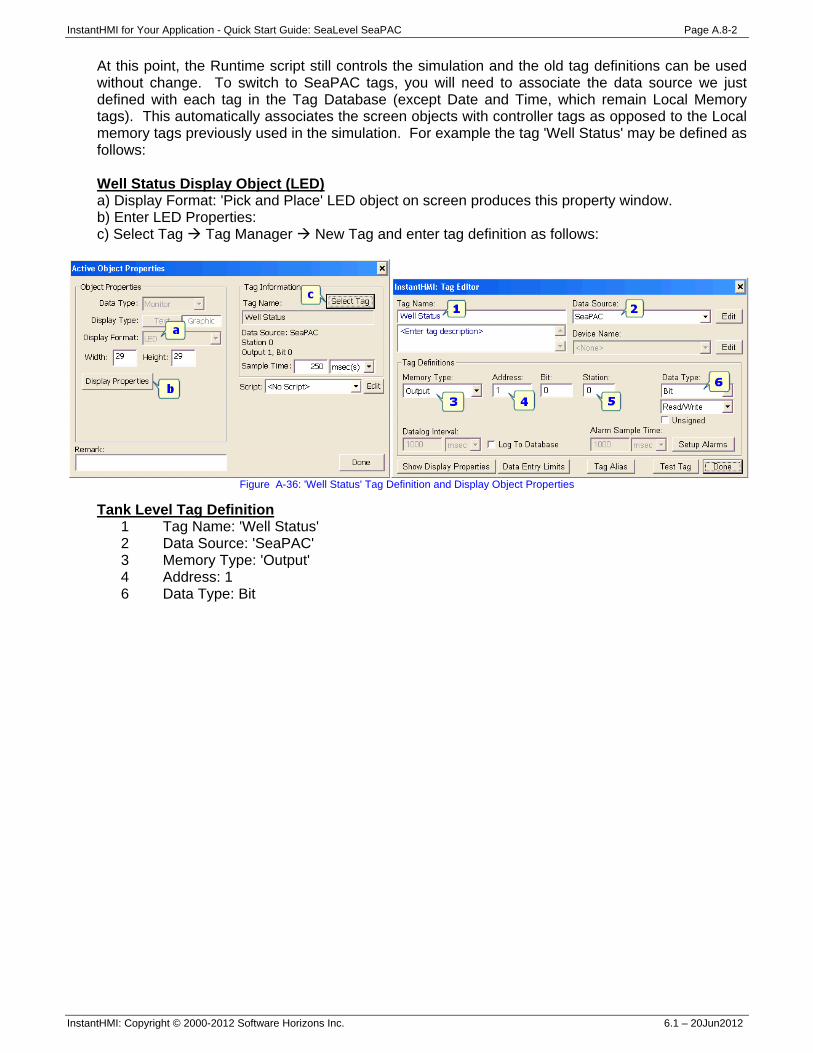
InstantHMI for Your Application - Quick Start Guide: SeaLevel SeaPAC Page A.8-2
InstantHMI: Copyright © 2000-2012 Software Horizons Inc. 6.1 – 20Jun2012
At this point, the Runtime script still controls the simulation and the old tag definitions can be used without change. To switch to SeaPAC tags, you will need to associate the data source we just defined with each tag in the Tag Database (except Date and Time, which remain Local Memory tags). This automatically associates the screen objects with controller tags as opposed to the Local memory tags previously used in the simulation. For example the tag 'Well Status' may be defined as follows: Well Status Display Object (LED) a) Display Format: 'Pick and Place' LED object on screen produces this property window. b) Enter LED Properties: c) Select Tag Tag Manager New Tag and enter tag definition as follows:
Figure A-36: 'Well Status' Tag Definition and Display Object Properties
Tank Level Tag Definition 1 Tag Name: 'Well Status' 2 Data Source: 'SeaPAC' 3 Memory Type: 'Output' 4 Address: 1 6 Data Type: Bit
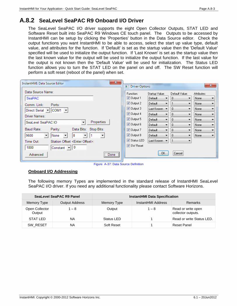
InstantHMI for Your Application - Quick Start Guide: SeaLevel SeaPAC Page A.8-3
InstantHMI: Copyright © 2000-2012 Software Horizons Inc. 6.1 – 20Jun2012
A.8.2 SeaLevel SeaPAC R9 Onboard I/O Driver The SeaLevel SeaPAC I/O driver supports the eight Open Collector Outputs, STAT LED and Software Reset built into SeaPAC R9 Windows CE touch panel. The Outputs to be accessed by InstantHMI can be setup by clicking the 'Properties' button in the Data Source editor. Check the output functions you want InstantHMI to be able to access, select the start up value type, default value, and attributes for the function. If 'Default' is set as the startup value then the 'Default Value' specified will be used to initialize the output function. If 'Last Known' is set as the startup value then the last known value for the output will be used to initialize the output function. If the last value for the output is not known then the 'Default Value' will be used for initialization. The Status LED function allows you to turn the STAT LED on the panel on and off. The SW Reset function will perform a soft reset (reboot of the panel) when set.
Figure A-37: Data Source Definition
Onboard I/O Addressing The following memory Types are implemented in the standard release of InstantHMI SeaLevel SeaPAC I/O driver. If you need any additional functionality please contact Software Horizons.
SeaLevel SeaPAC R9 Panel InstantHMI Data Specification
Memory Type Output Address Memory Type InstantHMI Address Remarks
Open Collector Output
1 – 8
Output 1 – 8
Read or write open collector outputs.
STAT LED NA Status LED 1 Read or write Status LED.
SW_RESET NA Soft Reset 1 Reset Panel

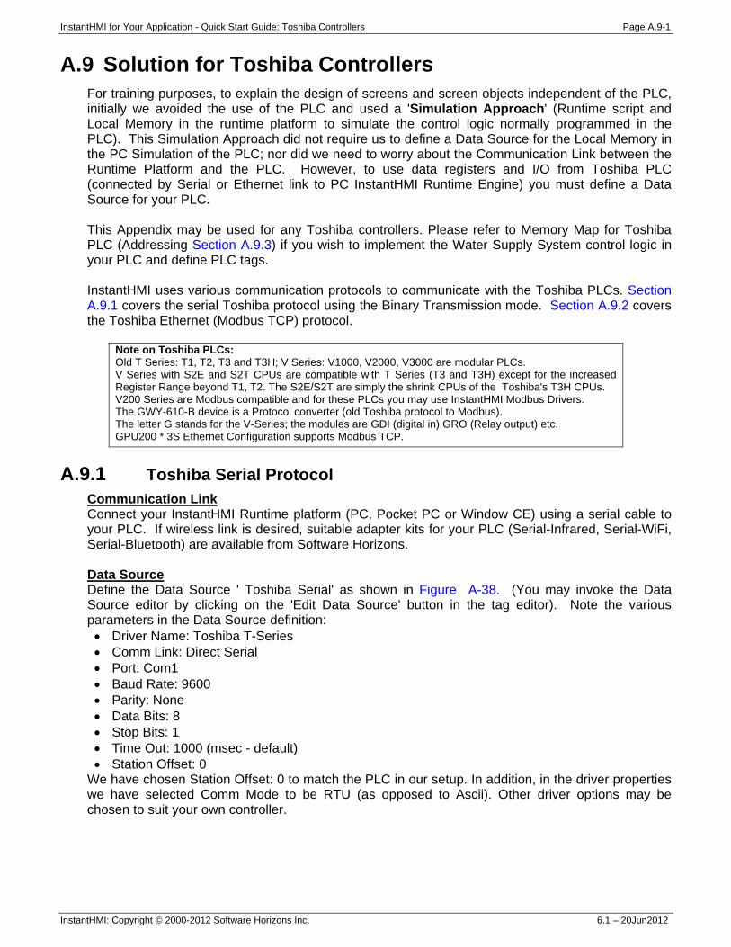
InstantHMI for Your Application - Quick Start Guide: Toshiba Controllers Page A.9-1
InstantHMI: Copyright © 2000-2012 Software Horizons Inc. 6.1 – 20Jun2012
A.9 Solution for Toshiba Controllers For training purposes, to explain the design of screens and screen objects independent of the PLC, initially we avoided the use of the PLC and used a 'Simulation Approach' (Runtime script and Local Memory in the runtime platform to simulate the control logic normally programmed in the PLC). This Simulation Approach did not require us to define a Data Source for the Local Memory in the PC Simulation of the PLC; nor did we need to worry about the Communication Link between the Runtime Platform and the PLC. However, to use data registers and I/O from Toshiba PLC (connected by Serial or Ethernet link to PC InstantHMI Runtime Engine) you must define a Data Source for your PLC. This Appendix may be used for any Toshiba controllers. Please refer to Memory Map for Toshiba PLC (Addressing Section A.9.3) if you wish to implement the Water Supply System control logic in your PLC and define PLC tags. InstantHMI uses various communication protocols to communicate with the Toshiba PLCs. Section A.9.1 covers the serial Toshiba protocol using the Binary Transmission mode. Section A.9.2 covers the Toshiba Ethernet (Modbus TCP) protocol.
Note on Toshiba PLCs: Old T Series: T1, T2, T3 and T3H; V Series: V1000, V2000, V3000 are modular PLCs. V Series with S2E and S2T CPUs are compatible with T Series (T3 and T3H) except for the increased Register Range beyond T1, T2. The S2E/S2T are simply the shrink CPUs of the Toshiba's T3H CPUs. V200 Series are Modbus compatible and for these PLCs you may use InstantHMI Modbus Drivers. The GWY-610-B device is a Protocol converter (old Toshiba protocol to Modbus). The letter G stands for the V-Series; the modules are GDI (digital in) GRO (Relay output) etc. GPU200 * 3S Ethernet Configuration supports Modbus TCP.
A.9.1 Toshiba Serial Protocol
Communication Link Connect your InstantHMI Runtime platform (PC, Pocket PC or Window CE) using a serial cable to your PLC. If wireless link is desired, suitable adapter kits for your PLC (Serial-Infrared, Serial-WiFi, Serial-Bluetooth) are available from Software Horizons. Data Source Define the Data Source ' Toshiba Serial' as shown in Figure A-38. (You may invoke the Data Source editor by clicking on the 'Edit Data Source' button in the tag editor). Note the various parameters in the Data Source definition: • Driver Name: Toshiba T-Series • Comm Link: Direct Serial • Port: Com1 • Baud Rate: 9600 • Parity: None • Data Bits: 8 • Stop Bits: 1 • Time Out: 1000 (msec - default) • Station Offset: 0
We have chosen Station Offset: 0 to match the PLC in our setup. In addition, in the driver properties we have selected Comm Mode to be RTU (as opposed to Ascii). Other driver options may be chosen to suit your own controller.
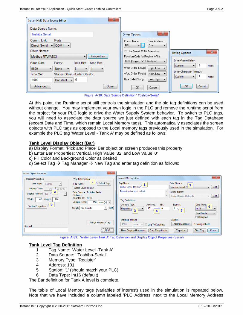
InstantHMI for Your Application - Quick Start Guide: Toshiba Controllers Page A.9-2
InstantHMI: Copyright © 2000-2012 Software Horizons Inc. 6.1 – 20Jun2012
Figure A-38: Data Source Definition ' Toshiba-Serial'
At this point, the Runtime script still controls the simulation and the old tag definitions can be used without change. You may implement your own logic in the PLC and remove the runtime script from the project for your PLC logic to drive the Water Supply System behavior. To switch to PLC tags, you will need to associate the data source we just defined with each tag in the Tag Database (except Date and Time, which remain Local Memory tags). This automatically associates the screen objects with PLC tags as opposed to the Local memory tags previously used in the simulation. For example the PLC tag 'Water Level - Tank A' may be defined as follows: Tank Level Display Object (Bar) a) Display Format: 'Pick and Place' Bar object on screen produces this property b) Enter Bar Properties: Vertical, High Value '32' and Low Value '0' c) Fill Color and Background Color as desired d) Select Tag Tag Manager New Tag and enter tag definition as follows:
Figure A-39: 'Water Level-Tank A' Tag Definition and Display Object Properties (Serial)
Tank Level Tag Definition 1 Tag Name: 'Water Level -Tank A' 2 Data Source: ' Toshiba-Serial' 3 Memory Type: 'Register' 4 Address: 101 5 Station: '1' (should match your PLC) 6 Data Type: Int16 (default)
The Bar definition for Tank A level is complete. The table of Local Memory tags (variables of interest) used in the simulation is repeated below. Note that we have included a column labeled 'PLC Address' next to the Local Memory Address
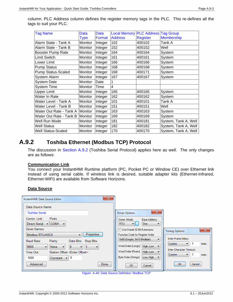
InstantHMI for Your Application - Quick Start Guide: Toshiba Controllers Page A.9-3
InstantHMI: Copyright © 2000-2012 Software Horizons Inc. 6.1 – 20Jun2012
column. PLC Address column defines the register memory tags in the PLC. This re-defines all the tags to suit your PLC.
Tag Name Data Type
Data Format
Local Memory Address
PLC AddressRegister
Tag Group Membership
Alarm State - Tank A Monitor Integer 102 400102 Tank A Alarm State - Tank B Monitor Integer 152 400152 Well Booster Pump Rate Monitor Integer 164 400164 System Limit Switch Monitor Integer 161 400161 System Lower Limit Monitor Integer 166 400166 System Pump Status Monitor Integer 168 400168 System Pump Status-Scaled Monitor Integer 168 400171 System System Alarm Monitor Integer 167 400167 System System Date Monitor Date 1 System Time Monitor Time 4 Upper Limit Monitor Integer 165 400165 System Water In Rate Monitor Integer 162 400162 System Water Level - Tank A Monitor Integer 101 400101 Tank A Water Level - Tank B Monitor Integer 151 400151 Well Water Out Rate - Tank A Monitor Integer 163 400163 System Water Out Rate - Tank B Monitor Integer 169 400169 System Well Run Mode Monitor Integer 181 400181 System, Tank A, WellWell Status Monitor Integer 182 400182 System, Tank A, WellWell Status-Scaled Monitor Integer 170 400170 System, Tank A, Well
A.9.2 Toshiba Ethernet (Modbus TCP) Protocol
The discussion in Section A.9.2 (Toshiba Serial Protocol) applies here as well. The only changes are as follows: Communication Link You connect your InstantHMI Runtime platform (PC, Pocket PC or Window CE) over Ethernet link instead of using serial cable. If wireless link is desired, suitable adapter kits (Ethernet-Infrared, Ethernet-WiFi) are available from Software Horizons. Data Source
Figure A-40: Data Source Definition 'Modbus TCP'
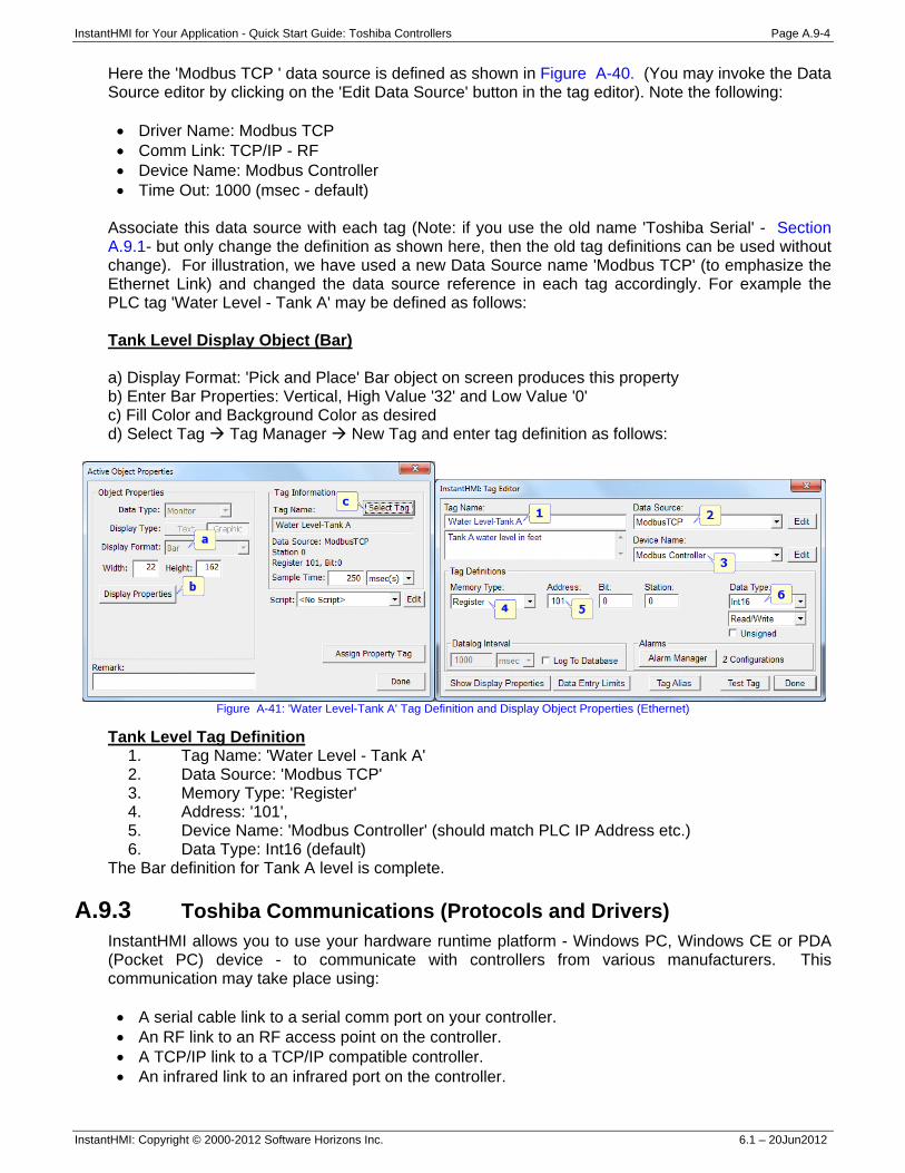
InstantHMI for Your Application - Quick Start Guide: Toshiba Controllers Page A.9-4
InstantHMI: Copyright © 2000-2012 Software Horizons Inc. 6.1 – 20Jun2012
Here the 'Modbus TCP ' data source is defined as shown in Figure A-40. (You may invoke the Data Source editor by clicking on the 'Edit Data Source' button in the tag editor). Note the following: • Driver Name: Modbus TCP • Comm Link: TCP/IP - RF • Device Name: Modbus Controller • Time Out: 1000 (msec - default)
Associate this data source with each tag (Note: if you use the old name 'Toshiba Serial' - Section A.9.1- but only change the definition as shown here, then the old tag definitions can be used without change). For illustration, we have used a new Data Source name 'Modbus TCP' (to emphasize the Ethernet Link) and changed the data source reference in each tag accordingly. For example the PLC tag 'Water Level - Tank A' may be defined as follows: Tank Level Display Object (Bar) a) Display Format: 'Pick and Place' Bar object on screen produces this property b) Enter Bar Properties: Vertical, High Value '32' and Low Value '0' c) Fill Color and Background Color as desired d) Select Tag Tag Manager New Tag and enter tag definition as follows:
Figure A-41: 'Water Level-Tank A' Tag Definition and Display Object Properties (Ethernet)
Tank Level Tag Definition 1. Tag Name: 'Water Level - Tank A' 2. Data Source: 'Modbus TCP' 3. Memory Type: 'Register' 4. Address: '101', 5. Device Name: 'Modbus Controller' (should match PLC IP Address etc.) 6. Data Type: Int16 (default)
The Bar definition for Tank A level is complete. A.9.3 Toshiba Communications (Protocols and Drivers)
InstantHMI allows you to use your hardware runtime platform - Windows PC, Windows CE or PDA (Pocket PC) device - to communicate with controllers from various manufacturers. This communication may take place using: • A serial cable link to a serial comm port on your controller. • An RF link to an RF access point on the controller. • A TCP/IP link to a TCP/IP compatible controller. • An infrared link to an infrared port on the controller.
InstantHMI for Your Application - Quick Start Guide: Toshiba Controllers Page A.9-5
InstantHMI: Copyright © 2000-2012 Software Horizons Inc. 6.1 – 20Jun2012
If your controller does not support Wireless RF communications (WiFi or Bluetooth) you may be able to use the RF-Kit from Software Horizons to convert the serial port on your controller to a Wireless RF connection. Similarly, if your controller does not have a built-in IR port, you may be able to use the IR-Kit from Software Horizons to convert the serial port on your controller to an IR port.
Please note that you must have the proper runtime engine installed on the target platform, and you must Register and Activate (see Appendix A in the InstantHMI manual) your InstantHMI software installation to communicate with your controller.
Toshiba Serial Communication Protocol-Driver 10 Note: Old Driver 14 (for older Toshiba PLC models EX14B, EX20+, EX40+, EX40H, EX28B, and Cutler Hammer D100) is obsolete and no longer supported. Old Driver 16 for Toshiba EC300 Loop Controller is also obsolete and no longer supported.
The communication link is used to transfer information between the runtime platform and your controller according to Toshiba protocol. The functions implemented in the standard release of InstantHMI Drivers 10 are listed in Addressing Section A.9.2. If you need any additional functions please contact Software Horizons. Setting up your PLC for Proper Communications InstantHMI uses a default setting of 9600 baud, no parity, 8 data bits, 1 stop bit. The Station Number is configurable via PLC configuration software (factory default is usually 1).
Step 1: Follow detailed installation instructions for your controller users manual to set up your PLC, modules and cabling.
Step 2: Make sure the PLC, modules and cables are installed correctly by testing your
installation using Controller Programming software. If you choose a lower/higher baud rate, or different Station Number; make sure the InstantHMI Data Source reflects any changes you make. Please see Section A.9.1 of this Manual for more information on how to configure data sources. If you are using a Stand-alone PDA version of InstantHMI (no LaunchPad), your data source can be edited by tapping Setup -> Comm Setup from the InstantHMI Main Menu on your PDA (See Section 3.1 in the InstantHMI Manual for more information). Serial Cable Connections Connect the PLC (EX-100, EX200B, EX500, M20, M40) Comm Link RS-422 port to the RS-232C port of your runtime platform using an RS-232 to RS-422 Converter (Cable 1) and connect the RS-232 port on the converter to your PC using cable 2. We will show cable 1 and 2 for Black Box Converter and B&B converter.
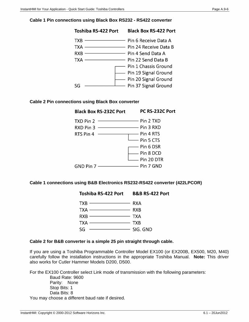
InstantHMI for Your Application - Quick Start Guide: Toshiba Controllers Page A.9-6
InstantHMI: Copyright © 2000-2012 Software Horizons Inc. 6.1 – 20Jun2012
Cable 1 Pin connections using Black Box RS232 - RS422 converter
Cable 2 Pin connections using Black Box converter
Cable 1 connections using B&B Electronics RS232-RS422 converter (422LPCOR)
Cable 2 for B&B converter is a simple 25 pin straight through cable. If you are using a Toshiba Programmable Controller Model EX100 (or EX200B, EX500, M20, M40) carefully follow the installation instructions in the appropriate Toshiba Manual. Note: This driver also works for Cutler Hammer Models D200, D500. For the EX100 Controller select Link mode of transmission with the following parameters:
Baud Rate: 9600 Parity: None Stop Bits: 1 Data Bits: 8
You may choose a different baud rate if desired.
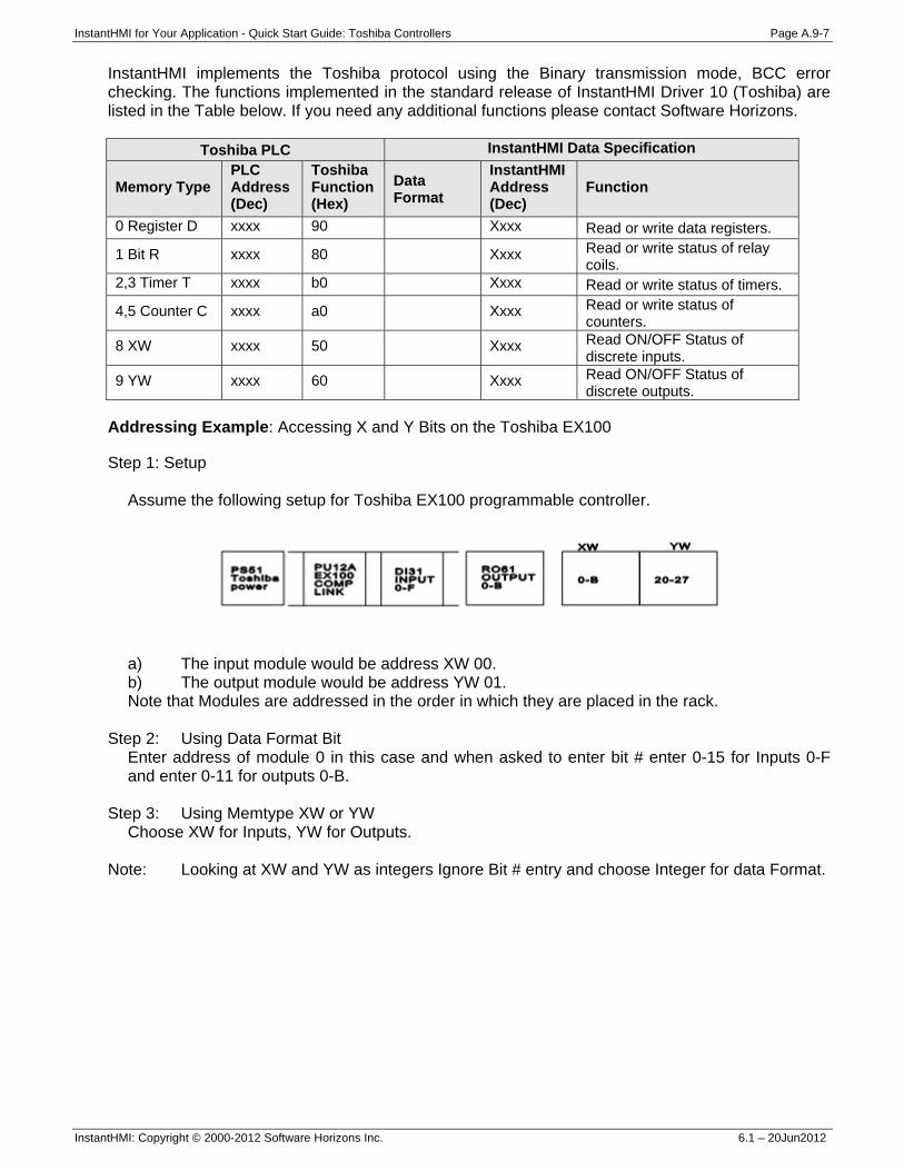
InstantHMI for Your Application - Quick Start Guide: Toshiba Controllers Page A.9-7
InstantHMI: Copyright © 2000-2012 Software Horizons Inc. 6.1 – 20Jun2012
InstantHMI implements the Toshiba protocol using the Binary transmission mode, BCC error checking. The functions implemented in the standard release of InstantHMI Driver 10 (Toshiba) are listed in the Table below. If you need any additional functions please contact Software Horizons.
Toshiba PLC InstantHMI Data Specification
Memory Type PLC Address (Dec)
Toshiba Function (Hex)
Data Format
InstantHMI Address (Dec)
Function
0 Register D xxxx 90 Xxxx Read or write data registers.
1 Bit R xxxx 80 Xxxx Read or write status of relay coils.
2,3 Timer T xxxx b0 Xxxx Read or write status of timers.
4,5 Counter C xxxx a0 Xxxx Read or write status of counters.
8 XW xxxx 50 Xxxx Read ON/OFF Status of discrete inputs.
9 YW xxxx 60 Xxxx Read ON/OFF Status of discrete outputs.
Addressing Example: Accessing X and Y Bits on the Toshiba EX100
Step 1: Setup
Assume the following setup for Toshiba EX100 programmable controller.
a) The input module would be address XW 00. b) The output module would be address YW 01. Note that Modules are addressed in the order in which they are placed in the rack.
Step 2: Using Data Format Bit
Enter address of module 0 in this case and when asked to enter bit # enter 0-15 for Inputs 0-F and enter 0-11 for outputs 0-B.
Step 3: Using Memtype XW or YW
Choose XW for Inputs, YW for Outputs. Note: Looking at XW and YW as integers Ignore Bit # entry and choose Integer for data Format.
InstantHMI for Your Application - Quick Start Guide: Toshiba Controllers Page A.9-8
InstantHMI: Copyright © 2000-2012 Software Horizons Inc. 6.1 – 20Jun2012
Toshiba Computer Link Protocol-Driver 41 Toshiba T-Series Programmable Controller If you are using a Toshiba Prosec T-Series Programmable Controller, carefully follow the installation instructions in the appropriate Toshiba Manual. Introduction InstantHMI allows you to use your hardware runtime platform - Windows PC, Windows CE or PDA (Pocket PC, Palm) device - to communicate with controllers from various manufacturers. This communication may take place using:
A serial cable link to a serial comm port on your controller. An RF link to an RF access point on the controller. A TCP/IP link to a TCP/IP compatible controller. An infrared link to an infrared port on the controller.
If your controller does not support Wireless RF communications (WiFi or Bluetooth) you may be able to use the RF-Kit from Software Horizons to convert the serial port on your controller to a Wireless RF connection. Similarly, if your controller does not have a built-in IR port, you may be able to use the IR-Kit from Software Horizons to convert the serial port on your controller to an IR port. Communication Protocol – Driver 41 The communication link is used to transfer information between the runtime platform and your controller according to the Toshiba Computer Link Protocol with checksum error checking. Please note that you must have the proper runtime engine installed on the target platform, and you must Register / Activate (see Appendix A in the InstantHMI manual) your InstantHMI software installation to communicate with your controller. Setting up your PLC for Proper Communications For the T-Series Controllers, InstantHMI uses Toshiba T-Series Computer Link Protocol with a default communication setting of 9600 baud, Odd Parity, 8 data bits, 1 stop bit. With some Toshiba controllers, the Station Number is configurable via PLC configuration software (factory default is 1). You may choose a lower/higher baud rate, or different Station Number if desired; make sure the InstantHMI Data Source reflects any changes you make. Please see Section 3.10 of the InstantHMI Manual for more information on how to configure data sources. If you are using a Stand-alone PDA version of InstantHMI (no LaunchPad), your data source can be edited by tapping Setup -> Comm Setup from the InstantHMI Main Menu on your handheld. Reference Section 9.2.1 in the InstantHMI Manual for more information. Communication Protocol The following functions are implemented in the standard release of InstantHMI Toshiba T-Series driver. If you need any additional functionality please contact Software Horizons.
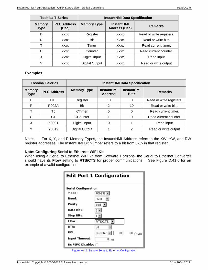
InstantHMI for Your Application - Quick Start Guide: Toshiba Controllers Page A.9-9
InstantHMI: Copyright © 2000-2012 Software Horizons Inc. 6.1 – 20Jun2012
Toshiba T-Series InstantHMI Data Specification
Memory Type
PLC Address (Dec)
Memory Type
InstantHMI Address (Dec) Remarks
D xxxx Register Xxxx Read or write registers. R xxxx Bit Xxxx Read or write bits. T xxxx Timer Xxxx Read current timer. C xxxx Counter Xxxx Read current counter.
X xxxx Digital Input Xxxx Read input
Y xxxx Digital Output Xxxx Read or write output Examples
Toshiba T-Series InstantHMI Data Specification
Memory Type PLC Address Memory Type
InstantHMI
Address InstantHMI
Bit # Remarks
D D10 Register 10 0 Read or write registers. R R002A Bit 2 10 Read or write bits. T T5 CTimer 5 0 Read current timer. C C1 CCounter 1 0 Read current counter.
X X0001 Digital Input 0 1 Read input
Y Y0012 Digital Output 1 2 Read or write output Note: For X, Y, and R Memory Types, the InstantHMI Address refers to the XW, YW, and RW register addresses. The InstantHMI Bit Number refers to a bit from 0-15 in that register. Note: Configuring Serial to Ethernet WiFi Kit When using a Serial to Ethernet WiFi kit from Software Horizons, the Serial to Ethernet Converter should have its Flow setting to RTS/CTS for proper communications. See Figure D.41.6 for an example of a valid configuration.
Figure A-42: Sample Serial to Ethernet Configuration
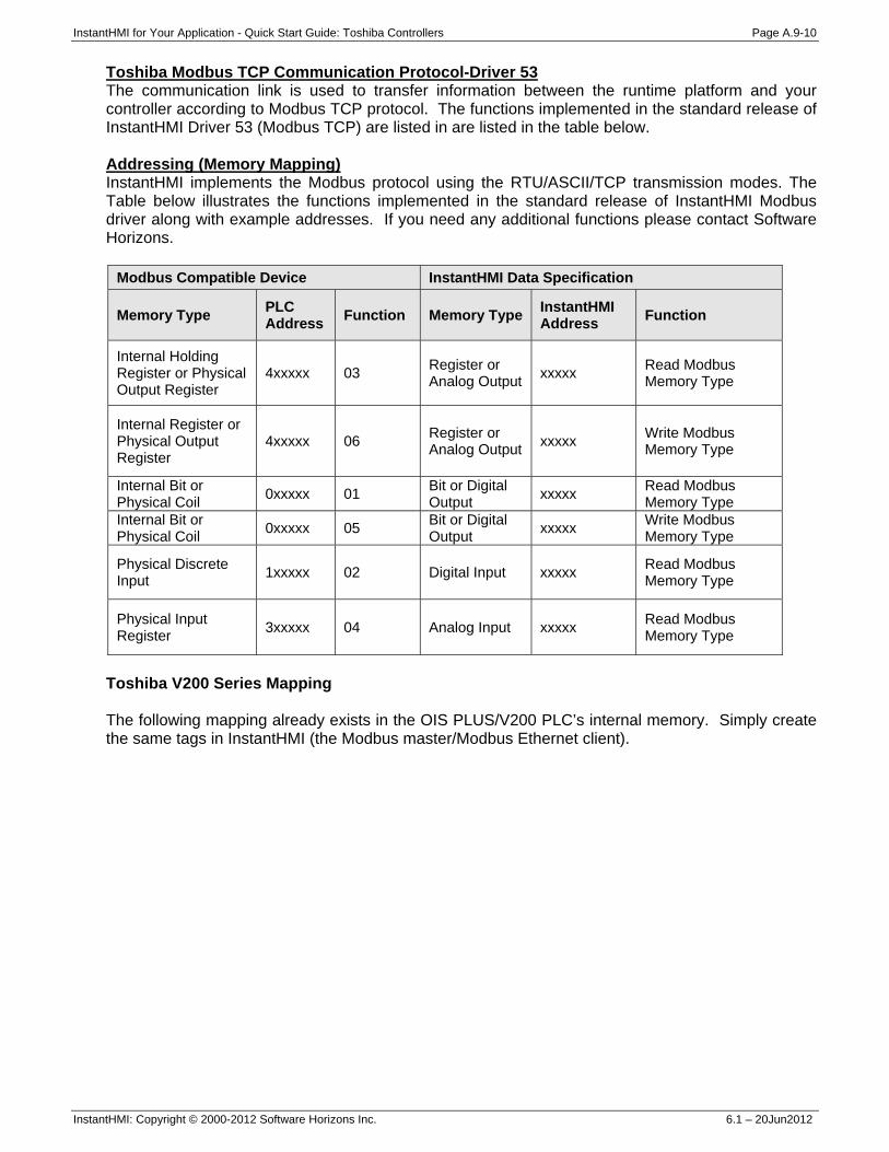
InstantHMI for Your Application - Quick Start Guide: Toshiba Controllers Page A.9-10
InstantHMI: Copyright © 2000-2012 Software Horizons Inc. 6.1 – 20Jun2012
Toshiba Modbus TCP Communication Protocol-Driver 53 The communication link is used to transfer information between the runtime platform and your controller according to Modbus TCP protocol. The functions implemented in the standard release of InstantHMI Driver 53 (Modbus TCP) are listed in are listed in the table below. Addressing (Memory Mapping) InstantHMI implements the Modbus protocol using the RTU/ASCII/TCP transmission modes. The Table below illustrates the functions implemented in the standard release of InstantHMI Modbus driver along with example addresses. If you need any additional functions please contact Software Horizons.
Modbus Compatible Device InstantHMI Data Specification
Memory Type PLC Address Function Memory Type InstantHMI
Address Function
Internal Holding Register or Physical Output Register
4xxxxx 03 Register or Analog Output xxxxx Read Modbus
Memory Type
Internal Register or Physical Output Register
4xxxxx 06 Register or Analog Output xxxxx Write Modbus
Memory Type
Internal Bit or Physical Coil 0xxxxx 01 Bit or Digital
Output xxxxx Read Modbus Memory Type
Internal Bit or Physical Coil 0xxxxx 05 Bit or Digital
Output xxxxx Write Modbus Memory Type
Physical Discrete Input 1xxxxx 02 Digital Input xxxxx Read Modbus
Memory Type
Physical Input Register 3xxxxx 04 Analog Input xxxxx Read Modbus
Memory Type
Toshiba V200 Series Mapping The following mapping already exists in the OIS PLUS/V200 PLC’s internal memory. Simply create the same tags in InstantHMI (the Modbus master/Modbus Ethernet client).
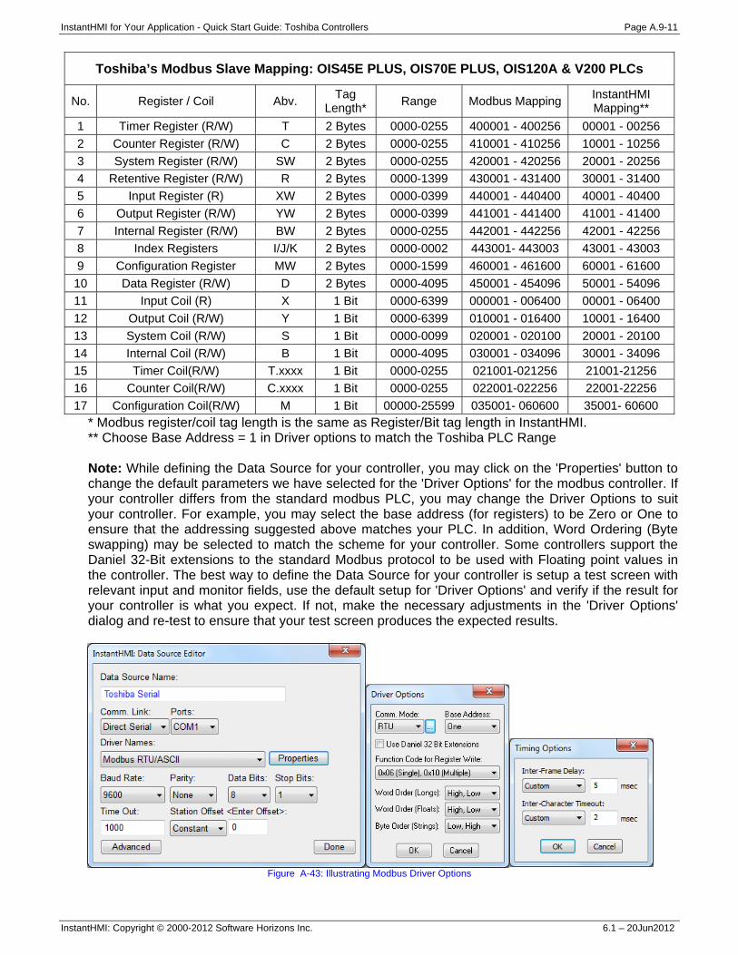
InstantHMI for Your Application - Quick Start Guide: Toshiba Controllers Page A.9-11
InstantHMI: Copyright © 2000-2012 Software Horizons Inc. 6.1 – 20Jun2012
Toshiba’s Modbus Slave Mapping: OIS45E PLUS, OIS70E PLUS, OIS120A & V200 PLCs
No. Register / Coil Abv. Tag Length* Range Modbus Mapping InstantHMI
Mapping** 1 Timer Register (R/W) T 2 Bytes 0000-0255 400001 - 400256 00001 - 00256 2 Counter Register (R/W) C 2 Bytes 0000-0255 410001 - 410256 10001 - 10256 3 System Register (R/W) SW 2 Bytes 0000-0255 420001 - 420256 20001 - 20256 4 Retentive Register (R/W) R 2 Bytes 0000-1399 430001 - 431400 30001 - 31400 5 Input Register (R) XW 2 Bytes 0000-0399 440001 - 440400 40001 - 40400 6 Output Register (R/W) YW 2 Bytes 0000-0399 441001 - 441400 41001 - 41400 7 Internal Register (R/W) BW 2 Bytes 0000-0255 442001 - 442256 42001 - 42256 8 Index Registers I/J/K 2 Bytes 0000-0002 443001- 443003 43001 - 43003 9 Configuration Register MW 2 Bytes 0000-1599 460001 - 461600 60001 - 61600 10 Data Register (R/W) D 2 Bytes 0000-4095 450001 - 454096 50001 - 54096 11 Input Coil (R) X 1 Bit 0000-6399 000001 - 006400 00001 - 06400 12 Output Coil (R/W) Y 1 Bit 0000-6399 010001 - 016400 10001 - 16400 13 System Coil (R/W) S 1 Bit 0000-0099 020001 - 020100 20001 - 20100 14 Internal Coil (R/W) B 1 Bit 0000-4095 030001 - 034096 30001 - 34096 15 Timer Coil(R/W) T.xxxx 1 Bit 0000-0255 021001-021256 21001-21256 16 Counter Coil(R/W) C.xxxx 1 Bit 0000-0255 022001-022256 22001-22256 17 Configuration Coil(R/W) M 1 Bit 00000-25599 035001- 060600 35001- 60600
* Modbus register/coil tag length is the same as Register/Bit tag length in InstantHMI. ** Choose Base Address = 1 in Driver options to match the Toshiba PLC Range Note: While defining the Data Source for your controller, you may click on the 'Properties' button to change the default parameters we have selected for the 'Driver Options' for the modbus controller. If your controller differs from the standard modbus PLC, you may change the Driver Options to suit your controller. For example, you may select the base address (for registers) to be Zero or One to ensure that the addressing suggested above matches your PLC. In addition, Word Ordering (Byte swapping) may be selected to match the scheme for your controller. Some controllers support the Daniel 32-Bit extensions to the standard Modbus protocol to be used with Floating point values in the controller. The best way to define the Data Source for your controller is setup a test screen with relevant input and monitor fields, use the default setup for 'Driver Options' and verify if the result for your controller is what you expect. If not, make the necessary adjustments in the 'Driver Options' dialog and re-test to ensure that your test screen produces the expected results.
Figure A-43: Illustrating Modbus Driver Options