Technological Change and Employee Motivation in a Telecom Operati
CoolLogicInstallati on, Operati on & Maintenance

Table of Contents
Introduction . . . . . . . . . . . . . . . . . . . . . . . . . . . . . . . . . . . . . . . . . 1
CoolLogic Control System . . . . . . . . . . . . . . . . . . . . . . . . . . . . 2-5
Standard Alarm Functions . . . . . . . . . . . . . . . . . . . . . . . . . . . . . 6
Standard Features . . . . . . . . . . . . . . . . . . . . . . . . . . . . . . . . . . 7-8
Start Up and Warranty Form . . . . . . . . . . . . . . . . . . . . . . . . 9-10
CoolLogic Screen Menu Hierarchy . . . . . . . . . . . . . . . . . . . . . . 11
Status User Access . . . . . . . . . . . . . . . . . . . . . . . . . . . . . . . . . . . 12
Setup User Access . . . . . . . . . . . . . . . . . . . . . . . . . . . . . . . . . . . 13
Service User Access . . . . . . . . . . . . . . . . . . . . . . . . . . . . . . . . . . 14
CoolLogic Control System Network Setup . . . . . . . . . . . . . . . . . . . .15
Appendix A . . . . . . . . . . . . . . . . . . . . . . . . . . . . . . . . . . . . . . . . . 16
Appendix B . . . . . . . . . . . . . . . . . . . . . . . . . . . . . . . . . . . . . . . . . 17
Appendix C . . . . . . . . . . . . . . . . . . . . . . . . . . . . . . . . . . . . . . . . . 18
Wiring Diagrams . . . . . . . . . . . . . . . . . . . . . . . . . . . . . . . . . . 19-23
Warranty Certificate . . . . . . . . . . . . . . . . . . . . . . . . . . . . . . . . . 24

1®
®
www.climacoolcorp.com
General Description The CoolLogic Control System provides leaving chilled and hot water liquid temperature control algorithms which maintain precise temperature control for cooling, heating, heat recovery and simultaneous heating and cooling applications . A compressor run time equalization sequence is given to ensure even distribution of compressor run time throughout the entire chiller bank . Chiller power consumption is minimized by indexing the most effi cient stages of cooling, optimizing heat transfer surface .
The ClimaCool® Ultimate Chiller Solution, “UCW/H/R” and “UGW” series, modular water-cooled chillers utilize the CoolLogic Control System to incorporate one or more modules . The controls are divided into two separate sections - the Master Control Panel and the module controller. The Master Control Panel governs all signifi cant events, timing and compressor staging, providing operator interface for all levels of setting and retrieving data . A single Master Control Panel has the ability to control a bank of modules with each unit having a unique address code by setting the two rotary switches of the master and each module controller . The Master Controller is address #01, module #1 is address #02, and so on (see fi gure 3 on page 3).
The module controller resides at each module location which senses and analyzes all pertinent data specifi c to that module’s compressor and water temperature operations .
Safety Throughout this manual warning, danger, caution and attention notices appear . Read these items carefully before attempting any installation, service or troubleshooting of the equipment . All labels on unit access panels must be observed .
DANGER: Immediate hazardous situation which, if not avoided, will result in death or serious injury .
WARNING: Potentially hazardous situation which, if not avoided, could result in death or serious injury .
CAUTION: Potentially hazardous situation or an unsafe practice which, if not avoided, could result in minor or moderate injury or product or property damage .
Introduction
Disconnect power supply (ies) before servicing. Refer servicing to qualifi ed service personnel. Electric shock hazard. May result in injury or death!
Unit to be serviced by qualifi ed personnel only. Refrigerant system under pressure. Relieve pressure before using torch. Recover refrigerant and store or dispose of properly.
Debrancher avant d’entre-prendre le dépannage de l’appareil. Consulter un réparateur qualifi e pour le dépannage. Risque de choc électrique. Résiltat de mai dans dommages ou la mort!
Conifer la maintenance à un technicien qualifi e. Le systéme frigorifi que sous pression. Décomprimer avant d’exposer à la fl amme. Récuperer le frigorigene et le stocker ou le détrulre correctement.
WARNING/AVERTISSEMENT
CAUTION/ATTENTION CAUTION/ATTENTION
To avoid possible injury or death due to electrical shock, open the power supply disconnect switch and secure it in an open position during installation.
Pour éviter les blessures ou la mort par électrocution, ouvrir la interrupteur de sécurité et fi xez-le en position ouverte lors de l’installation.
WARNING/AVERTISSEMENT
CAUTION/ATTENTIONUse only copper conductors for fi eld installed wiring. Unit termi-nals are not designed to accept other types of conductors.
Utilisez uniquement des conducteurs en cuivre pour le câblage. Bornes de l’unité ne sont pas conçus pour accepter d’autres types de con-ducteurs.

®
®
www.climacoolcorp.com2
CoolLogic Control System WiringA separate 115 volt power supply is required to power the CoolLogic Master Control Panel . Communication between the Master Control Panel and chiller modules requires a simple two-conductor 18 AWG shielded cable with drain rated at 60°C minimum, daisy chain connection . Control wiring cannot be installed in the same conduit as line voltage wiring or with wires that switch highly inductive loads such as contactor and relay coils. All wiring shall be in compliance with all local and national codes .
Field Connections between Master Control Panel and Module Controller• Arcnet or equivalent, 18-22 gauge AWG, two conductor
shielded cable with drain (under 50 feet)• Over 50 feet, contact factoryNote: Use the same polarity throughout the network segment .
Field Connections to the Master Control PanelField integration with the stand-alone Master Control Panel is simplified by the use of the following minimum input devices:• A remote start/stop input for scheduling • Differential pressure flow sensors for heating, cooling
and source (if applicable) water flows• Voltage/phase monitor (phase loss/phase reversal,
brown-out/black-out device) inputs• Chilled water inlet and outlet temperature sensors
and wells• Heating water inlet and outlet temperature
sensors and wells• Source water inlet and outlet temperature sensors
and wells if applicable
Field integration of the following output devices is standard:• Alarm output closes when any active latching alarm
condition occurs (parameter or compressor fault)• Chiller status output is closed whenever there is a call for
chiller operation and all flow, limit, phase, and interlock inputs deliver a closure signal indicating a present normal condition to allow for chiller operation
Figure 1 Master Control Panel
Field Connections to the ModulesThe Master Control Panel (see Figure 1)connects to the modules using the embedded ARC156 networking technology . It is well suited for real-time control applications in both the industrial and commercial marketplaces . ARC156 is a unique implementation of ARCnet but is similar to slave module/token passing (MS/TP). Speed is the main difference. ARC156 baud rate is 156K whereas MS/TP utilizes a maximum at 76.8K. ARC156 uses a separate communications co-processor to handle the network traffic and another processor to manage the program execution . Field connections are made at LVTB1 terminals 21, 22, and 23 at the CoolLogic controller and LVTC terminals 12, 13, and 14 at each chiller module .
Module ControllerThe module controller I/O Flex 6126 (see Figure 2) directly senses the control parameters that govern the specific module’s operation, such as evaporator and condenser leaving temperatures, both compressor’s winding temperatures, suction and discharge* temperatures and pressures .
*Discharge temperature sensing not available with SHC (Simultaneous Heating and Cooling) CoolLogic Control Systems .
Figure 2 Module Control Panel
Configuring the Master Controller (I/O Pro 812u) for ARC156
1 . Turn off the Master Controller’s (I/O Pro 812u) power2 . Using the rotary switches, set the Master Controller’s
address. Set the Tens (10’s) switch to the tens digit of the address, and the Ones (1’s) switch to the ones digit.Example (Figure 3): If the Master Controller’s address is 01, point the arrow on the Tens (10’s) switch to 0 and the arrow on the Ones (1’s) switch to 1.
CoolLogic Control System

3®
®
www.climacoolcorp.com
3 . Port 1 is the only port that speaks BACnet over ARC156 . Connect the communications wiring to Port 1 in thescrew terminals labeled Net+, Net-, and Shield (Gnd).The module controller references GND, and the master controller references SHIELD (see Figure 4 below).
4 . Set Port 1 Mode jumper to ARC156 (Figure 5) .
5 . Turn on the Master Controller’s power .6 . Default for the Master Board address will be 516800 .
Any variance from this device number cannot be used without ClimaCool Custom Programming . Consult factory if Custom Programming is required .
Dipswitch Settings1 . Enhanced Port 2a- must be OFF to allow BMS
communications through Port 2a . Do not turn ON .2 . IP Address- if IP communication is not used leave OFF
(default). If Custom IP address is used, turn ON (assigned) This allows the use of a custom IP address confi gurable in the BACview under FN0> IP.
3 . BMS Port- always set to ON when BMS is used . Allows BMS connection to Port 2 .
4 . Dip Switches 4 & 5 BAUD rate- this is the BAUD rate used by the BMS . See Figure 6 for various BAUD rate selections . ClimaCool currently supports the following Protocols: MS/TP m (see BMS for BAUD rate), N2 (always 9600), Modbus (see BMS for BAUD rate), Lon SLTA (see BMS for BAUD rate).
5 . Dip Switches 6, 7 & 8 BMS Port Settings- see Figure 7 for various Protocol selections/switch confi gurations (for Bacnet MSTP, use MS/TP m).
Figure 3 Rotary Switches
CoolLogic Control System
CLIMACOOL CORP. COOLLOGICDATE: MM/DD/YYYY T IME: HH:MM AM
CHWS TEMP: 0000.0F CWR TEMP: 0000.0F
PRESS ANY KEY TO CONTINUE
Figure 5
Figure 4
CoolLogic Control System Operator InterfaceThe CoolLogic Control System off ers an easy-to-use operator interface keypad (Figure 8) which includes a four-line by 40 character, back-lit LCD display panel, which is easy to navigate using logically grouped menus . This enables the user to access important information concerning set points, active temperatures, pressures, operating modes, alarm conditions, chiller scheduling, servicing, diagnostics and more .
Figure 8 BACview
If the keypad is left idle for 10 minutes, the default screen appears (Figure 9).
Figure 9: Default Screen
Figure 6 BAUD Rate
Figure 7 Protocol Selections
®
®
www.climacoolcorp.com4
COOLLOGIC CHILLER STATUS MENU
--> ALL MODULE COMPR UNLOAD STATUS FN5 --> MODULE SIZE STATUS / --> CHILLER OPER ST--> MOD1 COMP1 DATA / --> MOD1 COMP2 DATA --> MOD2 COMP1 DATA / --> MOD2 COMP2 DATA--> MOD3 COMP1 DATA / --> MOD3 COMP2 DATA--> MOD4 COMP1 DATA / --> MOD4 COMP2 DATA--> MOD5 COMP1 DATA / --> MOD5 COMP2 DATA--> MOD6 COMP1 DATA / --> MOD6 COMP2 DATA--> COMPR RUNTIMES / --> COMPR CYCLES--> COMPR ON/OFF STATUS--> EVAP STATUS / --> COND STATUS
[--> PREV] [--> CLOCKSET] [--> HOME] [--> ALARM]
COOLLOGIC SYSTEM SETUP FN2[--> GENERAL SYSTEM SETTINGS] FN4[--> HEAT & COOL SETPOINT MENUS][--> LEAD COMPR ROTATION SETUP][--> ALARM LOCKOUT RESET][--> CHILLER LOADING STATUS][--> SCHEDULES]
[--> PREV] [--> STATUS] [--> HOME] [--> ALARM]
COOLLOGIC SERVICE MENU SETUP FN 7[--> DIAGNOSTICS MANUAL MODE][--> ALL MODULE COMPR UNLOAD STATUS] FN5[--> ALL MODULES SENSOR CALIBRATION MENU][--> RESET ALL MODULE SENSOR OOR ALARMS][--> RESET COMP ALARMS & ALM DELAYS][--> MODULE WATER TEMP LIMITS][--> WATER & AIR TEMP LIMITS][--> CALIBRATE WATER TEMPS][--> LOCK WATER & AIR TEMPS][--> RESET COMP RUNTIMES & CYCLES] [--> PREV] [--> SETUP] [--> HOME] [-->ALARM]
MODULE EVENT HISTORY (100 MOST RECENT)====================ACTIVE ALARMS======================NONE IN BUFFER.====================ACTIVE FAULTS=======================NONE IN BUFFER.================RETURNED-TO-NORMAL (RTN)==============NONE IN BUFFER.================MANUALLY CLEARED (CLR)=================NONE IN BUFFER.
[--> PREV]
CoolLogic Control System
Alarm MenuUp to 100 of the most recent occurrences stored with date and time . Access to this log is available through the keypad .
Figure 14: Alarm Menu (FN+3 resets the alarm)
Figure 13: Service Menu (FN+7)At the end of this delay, the first compressor will start and after a five minute timeout, the display will change to the default screen (see page 3 Figure 9).
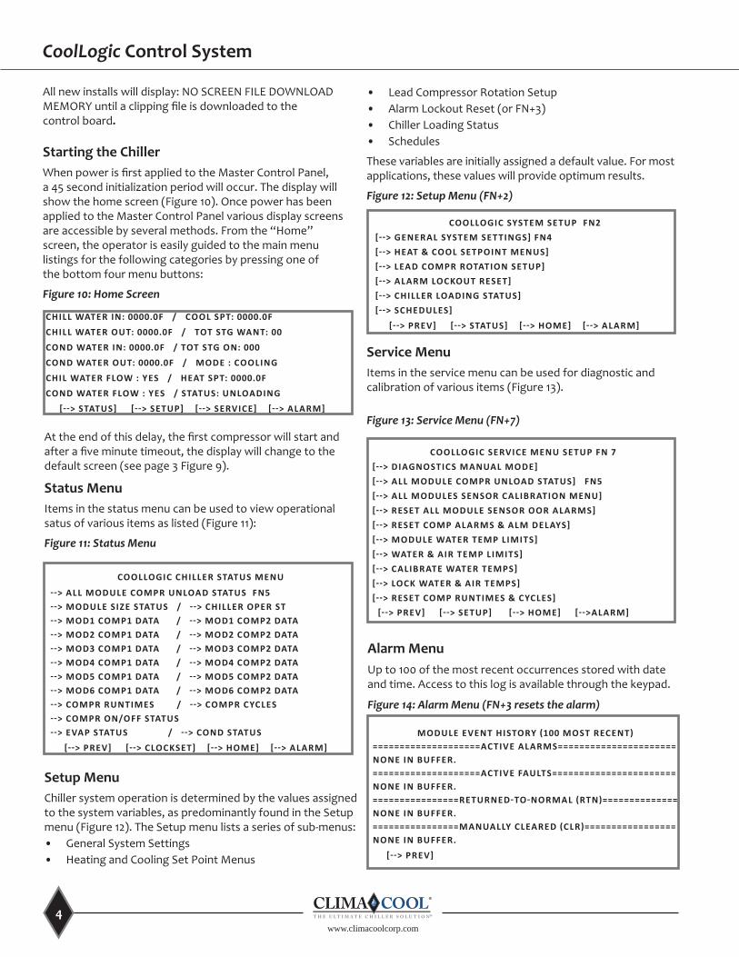
Status MenuItems in the status menu can be used to view operational satus of various items as listed (Figure 11):
Figure 11: Status Menu
Setup MenuChiller system operation is determined by the values assigned to the system variables, as predominantly found in the Setup menu (Figure 12). The Setup menu lists a series of sub-menus:• General System Settings• Heating and Cooling Set Point Menus
• Lead Compressor Rotation Setup• Alarm Lockout Reset (or FN+3)• Chiller Loading Status• Schedules
These variables are initially assigned a default value . For most applications, these values will provide optimum results .
Figure 12: Setup Menu (FN+2)
Service MenuItems in the service menu can be used for diagnostic and calibration of various items (Figure 13).
All new installs will display: NO SCREEN FILE DOWNLOAD MEMORY until a clipping file is downloaded to the control board.
Starting the ChillerWhen power is first applied to the Master Control Panel, a 45 second initialization period will occur . The display will show the home screen (Figure 10). Once power has been applied to the Master Control Panel various display screens are accessible by several methods . From the “Home” screen, the operator is easily guided to the main menu listings for the following categories by pressing one of the bottom four menu buttons:
Figure 10: Home Screen
CHILL WATER IN: 0000.0F / COOL SPT: 0000.0F
CHILL WATER OUT: 0000.0F / TOT STG WANT: 00
COND WATER IN: 0000.0F / TOT STG ON: 000
COND WATER OUT: 0000.0F / MODE : COOLING
CHIL WATER FLOW : YES / HEAT SPT: 0000.0F
COND WATER FLOW : YES / STATUS: UNLOADING
[--> STATUS] [--> SETUP] [--> SERVICE] [--> ALARM]
5®
®
www.climacoolcorp.com
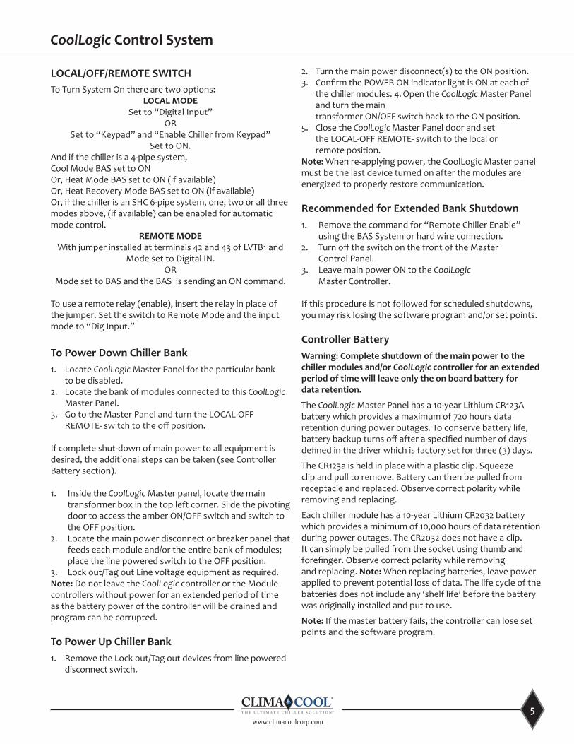
LOCAL/OFF/REMOTE SWITCH
To Turn System On there are two options: LOCAL MODE
Set to “Digital Input” OR
Set to “Keypad” and “Enable Chiller from Keypad” Set to ON .
And if the chiller is a 4-pipe system,Cool Mode BAS set to ONOr, Heat Mode BAS set to ON (if available)Or, Heat Recovery Mode BAS set to ON (if available)Or, if the chiller is an SHC 6-pipe system, one, two or all three modes above, (if available) can be enabled for automatic mode control .
REMOTE MODEWith jumper installed at terminals 42 and 43 of LVTB1 and
Mode set to Digital IN . OR
Mode set to BAS and the BAS is sending an ON command .
To use a remote relay (enable), insert the relay in place of the jumper . Set the switch to Remote Mode and the input mode to “Dig Input .”
To Power Down Chiller Bank1 . Locate CoolLogic Master Panel for the particular bank
to be disabled .2 . Locate the bank of modules connected to this CoolLogic
Master Panel .3 . Go to the Master Panel and turn the LOCAL-OFF
REMOTE- switch to the off position.
If complete shut-down of main power to all equipment is desired, the additional steps can be taken (see Controller Battery section).
1 . Inside the CoolLogic Master panel, locate the main transformer box in the top left corner . Slide the pivoting door to access the amber ON/OFF switch and switch to the OFF position .
2 . Locate the main power disconnect or breaker panel that feeds each module and/or the entire bank of modules; place the line powered switch to the OFF position .
3 . Lock out/Tag out Line voltage equipment as required . Note: Do not leave the CoolLogic controller or the Module controllers without power for an extended period of time as the battery power of the controller will be drained and program can be corrupted .
To Power Up Chiller Bank1 . Remove the Lock out/Tag out devices from line powered
disconnect switch .
CoolLogic Control System
2. Turn the main power disconnect(s) to the ON position.3. Confirm the POWER ON indicator light is ON at each of
the chiller modules . 4 . Open the CoolLogic Master Panel and turn the main transformer ON/OFF switch back to the ON position .
5 . Close the CoolLogic Master Panel door and set the LOCAL-OFF REMOTE- switch to the local or remote position .
Note: When re-applying power, the CoolLogic Master panel must be the last device turned on after the modules are energized to properly restore communication .
Recommended for Extended Bank Shutdown1 . Remove the command for “Remote Chiller Enable”
using the BAS System or hard wire connection . 2 . Turn off the switch on the front of the Master
Control Panel .3 . Leave main power ON to the CoolLogic
Master Controller .
If this procedure is not followed for scheduled shutdowns, you may risk losing the software program and/or set points . Controller BatteryWarning: Complete shutdown of the main power to the chiller modules and/or CoolLogic controller for an extended period of time will leave only the on board battery for data retention.
The CoolLogic Master Panel has a 10-year Lithium CR123A battery which provides a maximum of 720 hours data retention during power outages . To conserve battery life, battery backup turns off after a specified number of days defined in the driver which is factory set for three (3) days.
The CR123a is held in place with a plastic clip . Squeeze clip and pull to remove . Battery can then be pulled from receptacle and replaced . Observe correct polarity while removing and replacing .
Each chiller module has a 10-year Lithium CR2032 battery which provides a minimum of 10,000 hours of data retention during power outages . The CR2032 does not have a clip . It can simply be pulled from the socket using thumb and forefinger. Observe correct polarity while removing and replacing . Note: When replacing batteries, leave power applied to prevent potential loss of data . The life cycle of the batteries does not include any ‘shelf life’ before the battery was originally installed and put to use .
Note: If the master battery fails, the controller can lose set points and the software program .
®
®
www.climacoolcorp.com6
Standard Alarm Functions
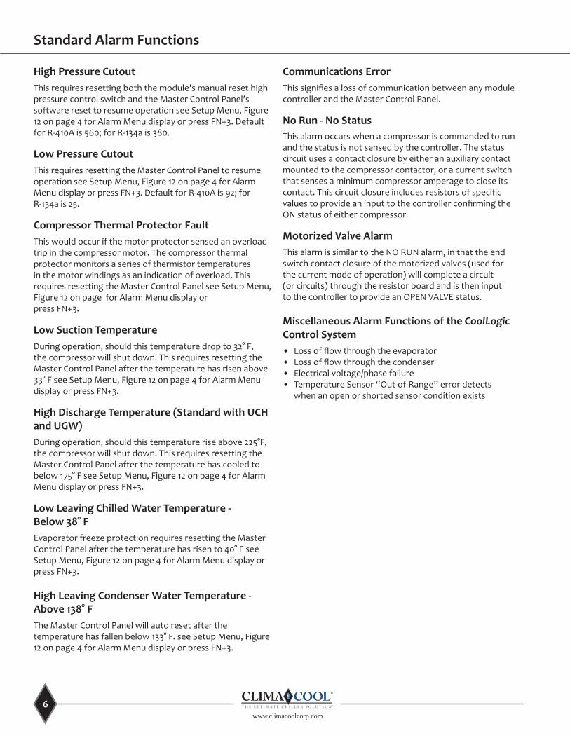
High Pressure CutoutThis requires resetting both the module’s manual reset high pressure control switch and the Master Control Panel’s software reset to resume operation see Setup Menu, Figure 12 on page 4 for Alarm Menu display or press FN+3 . Default for R-410A is 560; for R-134a is 380 .
Low Pressure CutoutThis requires resetting the Master Control Panel to resume operation see Setup Menu, Figure 12 on page 4 for Alarm Menu display or press FN+3 . Default for R-410A is 92; for R-134a is 25 .
Compressor Thermal Protector FaultThis would occur if the motor protector sensed an overload trip in the compressor motor . The compressor thermal protector monitors a series of thermistor temperatures in the motor windings as an indication of overload . This requires resetting the Master Control Panel see Setup Menu, Figure 12 on page for Alarm Menu display or press FN+3 .
Low Suction TemperatureDuring operation, should this temperature drop to 32° F, the compressor will shut down . This requires resetting the Master Control Panel after the temperature has risen above 33° F see Setup Menu, Figure 12 on page 4 for Alarm Menu display or press FN+3 .
High Discharge Temperature (Standard with UCH and UGW)During operation, should this temperature rise above 225°F, the compressor will shut down . This requires resetting the Master Control Panel after the temperature has cooled to below 175° F see Setup Menu, Figure 12 on page 4 for Alarm Menu display or press FN+3 .
Low Leaving Chilled Water Temperature - Below 38° FEvaporator freeze protection requires resetting the Master Control Panel after the temperature has risen to 40° F see Setup Menu, Figure 12 on page 4 for Alarm Menu display or press FN+3 .
High Leaving Condenser Water Temperature - Above 138° FThe Master Control Panel will auto reset after the temperature has fallen below 133° F . see Setup Menu, Figure 12 on page 4 for Alarm Menu display or press FN+3 .
Communications Error This signifies a loss of communication between any module controller and the Master Control Panel .
No Run - No StatusThis alarm occurs when a compressor is commanded to run and the status is not sensed by the controller . The status circuit uses a contact closure by either an auxiliary contact mounted to the compressor contactor, or a current switch that senses a minimum compressor amperage to close its contact. This circuit closure includes resistors of specific values to provide an input to the controller confirming the ON status of either compressor .
Motorized Valve AlarmThis alarm is similar to the NO RUN alarm, in that the end switch contact closure of the motorized valves (used for the current mode of operation) will complete a circuit (or circuits) through the resistor board and is then input to the controller to provide an OPEN VALVE status .
Miscellaneous Alarm Functions of the CoolLogic Control System• Loss of flow through the evaporator• Loss of flow through the condenser • Electrical voltage/phase failure• Temperature Sensor “Out-of-Range” error detects
when an open or shorted sensor condition exists

7®
®
www.climacoolcorp.com
Chilled Water Flow SensorThe Master Control Panel has an input for a differential pressure sensor, which measures and displays pressure drops across the chilled water main headers. If the differential pressure drops below a predetermined setting for a fixed period of time after the chiller receives a “RUN” input signal, the chiller will not be allowed to run and a chilled water flow alarm condition is displayed. The alarm condition must be resolved, flow re-established and a minimum pressure differential acknowledged by the differential pressure sensor. The alarm clears automatically which constitutes an “OK to RUN” status . The alarm condition is logged for retention in the most recent 100 alarms .
Condenser Water Flow Sensor
The Master Control Panel has an input for a differential pressure sensor, which measures and displays pressure drops across the condenser water main headers. If the differential pressure drops below a predetermined setting for a fixed period of time after the chiller receives a “RUN” input signal, the chiller will not be allowed to run and a condenser water flow alarm condition is displayed. This alarm condition must be resolved and flow re-established and a minimum pressure differential acknowledged by the differential pressure sensor. The alarm clears automatically and the alarm condition is logged for permanent retention of the most recent 100 alarms. This will constitute an “OK to RUN” status.
Voltage/Phase MonitorVoltage/phase monitors are factory supplied for field installation with the CoolLogic Master Control Panel . The voltage/phase monitor helps guard the chiller bank against voltage fluctuations, phase failure or phase reversal conditions. The voltage phase monitor will be field installed and connected to the main three phase power panel that feeds all the installed modules . Two low voltage control wires are connected to the CoolLogic Master Control Panel, terminals 40 and 41 of LVTB1, and must be field installed as well along with the power wiring . Do not install control wiring in the same conduit as line voltage wiring or with wires that switch highly inductive loads such as contactor and relay coils.
Install one (1) monitor per bank at main power distribution panel to monitor voltage and phasing of power to the modules. See Wiring Diagram on page 23.
Chilled/Heating Water Reset The Master Control Panel can be programmed to reset the leaving water temperature set point using a hard wired input voltage or current signal, or the voltage input can be modified via a BAS command . The reset functions are optional and must be activated through the appropriate setup menus . If
Standard Features
the chiller is operating and it receives a chilled water reset command, the leaving chilled water temperature setting will be allowed to ramp toward the new setting at a rate of 2°F every seven minutes . When the chiller is not operating and it receives a chilled water reset command, the leaving chilled water temperature setting will be fully reset immediately .
External Chilled Water Set Point Option
The Master Control Panel provides an input that accepts either 2-10 VDC or 4-20 mA signals to set the leaving chilled water set point. This input defines the set point and is not a reset (or offset) function. This input is used with generic Building Automation System (BAS) installations. The 2-10 VDC and 4-20 mA ranges each correspond to a preset range from the minimum chilled water set point to the maximum chilled water set point .
External Condenser Water Set Point Option
Associated with heat recovery chillers, the Master Control Panel provides an input that accepts either 2-10 VDC and 4-20 mA signals to set the leaving condenser water set point . This input defines the set point and is not a reset (or offset) function . This input is used with generic BAS installations . The 2-10 VDC and 4-20 mA ranges each correspond to a preset range from the minimum condenser water set point to the maximum condenser water set point .
Demand (or Load) LimitingTo limit the number of compressors that can be simultaneously energized, a demand limit control is available . The Master Control Panel provides an input channel that accepts either 2-10 VDC and 4-20 mA signals to set the maximum number of compressor stages allowable at any one time . This input is typically used with generic BAS installations . The 2-10 VDC and 4-20 mA ranges each correspond to a range from 0% to 100% of the total available compressor stages .
Alarm OutputThe relay output contact is closed whenever there is an active latching or non-latching alarm condition present relative to a fault parameter .
Chiller Status OutputThe relay output contact is closed whenever all input signals to the chiller are present and normal, indicating the requirement for the chiller to operate when able .

®
®
www.climacoolcorp.com8
Chilled Water Temperature Sensor Connections
Chilled water temperature monitoring (entering and leaving) is a standard feature of the CoolLogic Control System . It is accomplished by using a factory supplied pair of sensors and sensor wells which are field installed into ½” weld-o-lets (field supplied and installed onto the main water headers) within 60” of the entering and leaving chilled water locations . Note: Sensors must be fully inserted into the well to obtain proper readings and must be 2 ½ pipe diameter minimum before or after an elbow.
Condenser Water Temperature Sensor Connections
Condenser water temperature monitoring (entering and leaving) is a standard feature of the CoolLogic Control System . It is accomplished by using a factory supplied pair of sensors and sensor wells which are field installed into ½” weld-o-lets (field supplied and installed onto the main water headers) within 60” of the entering and leaving chilled water locations . Note: Sensors must be fully inserted into the well to obtain proper readings and must be 2 ½ pipe diameter minimum before or after an elbow.
Building Automation System (BAS) InterfaceInternal operational information is available where the chiller is to be integrated into a building system and monitored by the equipment of a controls manufacturer . Available protocols built into the CoolLogic Control System as standard are:
• BACnet • MODBUS • N2* • LonWorks**N2 and LonWorks require special programming/points list . Limit point polling to a max of 50 points at not more than 20 second intervals .
LonWorks® LonTalk Communications Interface Option
The Master Control Panel provides an optional LonTalk communication interface between the chiller and the BAS . Additional hardware is required (Echelon SLTA-10 communications card) to provide “gateway” functionality between a LonTalk compatible device and the CoolLogic Control System .
Compressor UnloadingCompressor unloading routines are programmed into each module controller . When any one of the module or compressor control parameters approaches a pre-limit condition, the CoolLogic Control System executes
appropriate compressor unloading commands to avoid compressor lockout, thus maximizing the chiller system on time . The FN5 menu can be accessed to view UNLOAD conditions when they are active .
Compressor Minimum Off DelayWhen a compressor is turned off, the compressor will remain off for this period of time. The default minimum off delay is 200 seconds .
Compressor Minimum On DelayWhen a compressor is turned on, the compressor will remain on for this period of time . This time can be cut short if an alarm condition is predicted . The default minimum on is 90 seconds .
Standard Features

9®
®
www.climacoolcorp.com
Note: For Reference Only . Each model will contain various menu items .
Start Up and Warranty Form: CoolLogic Master Controller Page 1 of 2 Project Name: ___________________________ ________________________________________ Start-Up Date: ___________________________ Chiller # _______ Bank # _________ (FN+2)
Chiller Control Type …………………… _________________ Chiller Control Source ………………… _________________ Enable Chiller from Keypad?.……… _________ Module Ref Type ……………………….. ___________ Chiller Model Type …………………….. ___________ Cool Design Delta Temp …………….. _‐10.0______ Heat Design Delta Temp ……………. _10.0______ (FN+2) then “Module Size Selector”
Module1 Size…………………………………………….. _______ Module 2 Size …………………………………………… _______ Module 3 Size …………………………………………… _______ Module 4 Size …………………………………………… _______ Module 5 Size ………………………………………….… _______ Module 6 Size …………………………………………… _______ (FN+6) then “Module Water Out Temp Limits”
Module Evap Water Out Low Limit………. _________ Module Evap Water Out Hi Limit.…………. _________ Module Cond Water Out Low Limit………. _________ Module Cond Water Out Hi Limit…………. _______*_
(FN+8) then “Main Water & Air Temp Limits”
Evap Water In Low Limit……………………. ________ Evap Water In Hi Limit…………….…………. ________ Evap Water Out Low Limit…………………. ________ Evap Water Out Hi Limit………….…………. ________ Cond Water In Low Limit………….………… ________ Cond Water In Hi Limit………….……..……. ________ Cond Water Out Low Limit………….……… ________ Cond Water Out Hi Limit………….…………. ________ (FN+8) then “Cool PID Stage #1 Setup”
Stage 1 Cool PID P‐Gain………………….. ______ Stage 1 Cool PID I‐Gain…………………… ______ Cooling PID Rise ……………………………… ______ Cooling PID Fall………………………………. ______ Cool Central Setpoint Offset…………… ______ Stage 1 Heat PID P‐Gain.………………… ______ Stage 1 Heat PID I‐Gain………………….. ______ Heating PID Rise……………………………. ______ Heating PID Fall…………………………….. ______ Heat Central Setpoint Offset…………. ______ (FN+6) then “Freeze Target Setpoint Menu”
Freeze Target Setpoint…………….. ______
Startup and Warranty Form
Start Up and Warranty Form: CoolLogic Master Controller Page 1 of 2 Project Name: ___________________________ ________________________________________ Start-Up Date: ___________________________ Chiller # _______ Bank # _________ (FN+2)
Chiller Control Type …………………… _________________ Chiller Control Source ………………… _________________ Enable Chiller from Keypad?.……… _________ Module Ref Type ……………………….. ___________ Chiller Model Type …………………….. ___________ Cool Design Delta Temp …………….. _‐10.0______ Heat Design Delta Temp ……………. _10.0______ (FN+2) then “Module Size Selector”
Module1 Size…………………………………………….. _______ Module 2 Size …………………………………………… _______ Module 3 Size …………………………………………… _______ Module 4 Size …………………………………………… _______ Module 5 Size ………………………………………….… _______ Module 6 Size …………………………………………… _______ (FN+6) then “Module Water Out Temp Limits”
Module Evap Water Out Low Limit………. _________ Module Evap Water Out Hi Limit.…………. _________ Module Cond Water Out Low Limit………. _________ Module Cond Water Out Hi Limit…………. _______*_
(FN+8) then “Main Water & Air Temp Limits”
Evap Water In Low Limit……………………. ________ Evap Water In Hi Limit…………….…………. ________ Evap Water Out Low Limit…………………. ________ Evap Water Out Hi Limit………….…………. ________ Cond Water In Low Limit………….………… ________ Cond Water In Hi Limit………….……..……. ________ Cond Water Out Low Limit………….……… ________ Cond Water Out Hi Limit………….…………. ________ (FN+8) then “Cool PID Stage #1 Setup”
Stage 1 Cool PID P‐Gain………………….. ______ Stage 1 Cool PID I‐Gain…………………… ______ Cooling PID Rise ……………………………… ______ Cooling PID Fall………………………………. ______ Cool Central Setpoint Offset…………… ______ Stage 1 Heat PID P‐Gain.………………… ______ Stage 1 Heat PID I‐Gain………………….. ______ Heating PID Rise……………………………. ______ Heating PID Fall…………………………….. ______ Heat Central Setpoint Offset…………. ______ (FN+6) then “Freeze Target Setpoint Menu”
Freeze Target Setpoint…………….. ______
®
®
www.climacoolcorp.com10
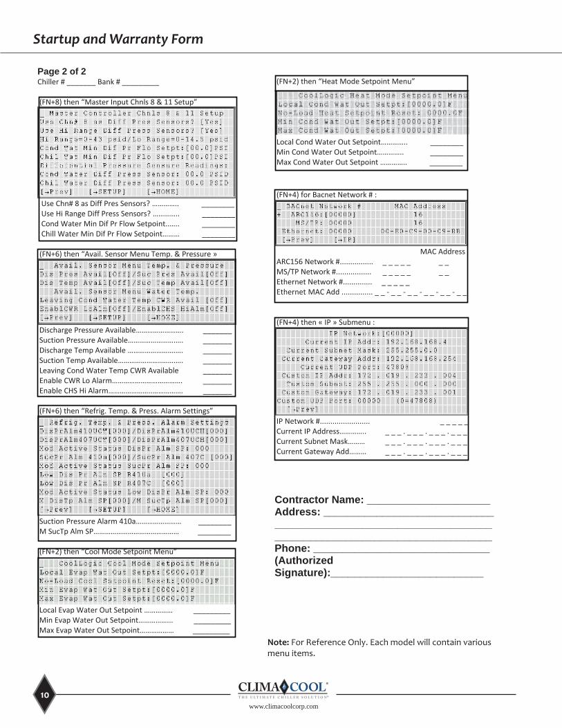
Page 2 of 2 Chiller # _______ Bank # _________ (FN+8) then “Master Input Chnls 8 & 11 Setup”
Use Chn# 8 as Diff Pres Sensors? ………….. ________ Use Hi Range Diff Press Sensors? ………….. ________ Cond Water Min Dif Pr Flow Setpoint..….. ________ Chill Water Min Dif Pr Flow Setpoint……… ________ (FN+6) then “Avail. Sensor Menu Temp. & Pressure »
Discharge Pressure Available……………………. _______ Suction Pressure Available…………………….…. _______ Discharge Temp Available …………………….…. _______ Suction Temp Available…………………..…….…. _______ Leaving Cond Water Temp CWR Available _______ Enable CWR Lo Alarm………………………………. _______ Enable CHS Hi Alarm…………………..……………. _______ (FN+6) then “Refrig. Temp. & Press. Alarm Settings”
Suction Pressure Alarm 410a…………………… ________ M SucTp Alm SP……………………………………… ________ (FN+2) then “Cool Mode Setpoint Menu”
Local Evap Water Out Setpoint …………… _________ Min Evap Water Out Setpoint……………... _________ Max Evap Water Out Setpoint……………… _________
(FN+2) then “Heat Mode Setpoint Menu” Local Cond Water Out Setpoint………….. ________ Min Cond Water Out Setpoint………….. ________ Max Cond Water Out Setpoint ………….. ________ (FN+4) for Bacnet Network # :
MAC Address ARC156 Network #................ _ _ _ _ _ _ _ MS/TP Network #................. _ _ _ _ _ _ _ Ethernet Network #.............. _ _ _ _ _ Ethernet MAC Add ............... _ _ ‐ _ _ ‐ _ _ ‐ _ _ ‐ _ _ ‐ _ _ (FN+4) then « IP » Submenu :
IP Network #........................ _ _ _ _ _ Current IP Address………….. _ _ _ . _ _ _ . _ _ _ . _ _ _ Current Subnet Mask……… _ _ _ . _ _ _ . _ _ _ . _ _ _ Current Gateway Add……… _ _ _ . _ _ _ . _ _ _ . _ _ _ Contractor Name: _____________________ Address: _____________________________ _____________________________________ _____________________________________ Phone: ______________________________ (Authorized Signature):__________________________
Note: For Reference Only . Each model will contain various menu items .
Startup and Warranty Form

11®
®
www.climacoolcorp.com
User Access - Home Screen (Example Only)
HOME
STATUS SETUP (FN2) SERVICE (FN7) ALARM
CoolLogic Screen Menu Hierarchy
BACview Menu
FN1 – PREV – Move back to last screenFN2 – General System Settings • Heat and Cool Set Points • Module/Compressor StatusFN3 – Alarm Menu - Module and Master Alarm ResetsFN4 – BAS Confi guration Screen Used for BAS system integrationsFN5 – Module Unload StatusFN6 – Module Level Confi guration • Module Temperature and Pressure Set Points • Module Valve and Fan Confi gurations
FN6 – Module Level Confi guration • Module Temperature and Pressure Set Points • Module Valve and Fan Confi gurationsFN7 – Diagnostic Screen • Manual Mode • Sensor Calibration • Module Water Temperature LimitFN8 – Master Level Confi gurations • Module Size Selector • PID – Cooling & Heating • Water Temperature Limits • External Input Confi gurations – Temp Resets, DPTFN9 – User Level Password Confi gurationFN0 - IP address or the Mac addressUsed for BAS system integrations

®
®
www.climacoolcorp.com12
M1C1 SUC PR: 0000.0PSI / MODULE 1 COMP 1SUC SUPERHT: 0000.0F / CH WATER IN: 0000.0FM1C1 SUC TP: 0000.0F / CH WATER OUT: 0000.0FM1C1 DIS PR: 0000PSI / M1C1 DIS TP: 0000.0FM1C1 STATUS: OFF / CD WATER IN: 0000.0FM1C1 FAIL: OFF / CD WATER OUT: 0000.0FM1C1 RUNTIME: 0000.0H / M1C1 CYCLES: 00000M1C1 MIN RUNTIME: OFF M1C1 MIN OFF TIME: OFFLOWEST HD PRES: 0000/CDMV PID OUT: 000.0 CDMV PID VDC SCALED OUT: 00.00 [--> PREV] [--> SETUP] [--> HOME] [-->ALARM]
COOLLOGIC COMPRESSOR ON/OFF STATUSM1C1 STATUS: OFF / M4C1 STATUS: OFFM1C2 STATUS: OFF / M4C2 STATUS: OFFM2C1 STATUS: OFF / M5C1 STATUS: OFFM2C2 STATUS: OFF / M5C2 STATUS: OFFM3C1 STATUS: OFF / M6C1 STATUS: OFFM3C2 STATUS: OFF / M6C2 STATUS: OFF [--> PREV] [--> SETUP] [--> HOME] [-->ALARM]
COOLLOGIC MODULE 1 COMPR UNLOAD STATUSM1C1 LOW SUCT PRESS UNLOAD : OFFM1C2 LOW SUCT PRESS UNLOAD : OFFM1C1 LOW SUCT TEMP UNLOAD : OFFM1C2 LOW SUCT TEMP UNLOAD : OFFM1 EVAP FREEZE TEMP UNLOAD : OFFM1 COND WATOUT TEMP UNLOAD : OFFM1C1 HIGH DIS PRESS UNLOAD : OFFM1C2 HIGH DIS PRESS UNLOAD : OFFM1C1 HIGH DIS TEMP UNLOAD : OFFM1C2 HIGH DIS TEMP UNLOAD : OFF [--> PREV] [--> SETUP] [--> HOME] [-->ALARM]
COOLLOGIC COMPRESSOR CYCLE STATUSM1C1 CYCLES: 00000 / M4C1 CYCLES: 00000M1C2 CYCLES: 00000 / M4C2 CYCLES: 00000M2C1 CYCLES: 00000 / M5C1 CYCLES: 00000M2C2 CYCLES: 00000 / M5C2 CYCLES: 00000M3C1 CYCLES: 00000 / M6C1 CYCLES: 00000M3C2 CYCLES: 00000 / M6C2 CYCLES: 00000 [--> PREV] [--> SETUP] [--> HOME] [-->ALARM]
Status User Access
COND WATER TEMP & PUMP STATUSCND H2O IN: 0000.0F / CND H2O OUT: 0000.0FCOND FLOW STATUS: OFFCND PUMP#1 STAT: OFF / CND PUMP#2 STAT: OFFCOND WATER DIFF PRESS SENSOR: 00.0 PSID [--> PREV] [--> SETUP] [--> STATUS]
COOLLOGIC CHILLER STATUS MENU --> ALL MODULE COMPR UNLOAD STATUS FN5 --> MODULE SIZE STATUS / CHILLER OPER ST --> MOD 1 COMP 1 DATA / MOD 1 COMP 2 DATA --> MOD 2 COMP 1 DATA / MOD 2 COMP 2 DATA --> MOD 3 COMP 1 DATA / MOD 3 COMP 2 DATA --> MOD 4 COMP 1 DATA / MOD 4 COMP 2 DATA --> MOD 5 COMP 1 DATA / MOD 5 COMP 2 DATA --> MOD 6 COMP 1 DATA / MOD 6 COMP 2 DATA --> COMPR RUNTIME / COMPR CYCLES --> COMPR ON/OFF STATUS --> EVAP STATUS / COND STATUS [--> PREV] [--> CLOCKSET] [--> HOME] [-->ALARM]
Compr Cycles Status
Compr Run-times Status
Mod1 Comp1 Data
Chiller Operating Status
Module Size Status
Module Compr Unload Functions F5
Cond Status
Evap Status
Compr ON/OFF Status
COOLLOGIC ALL MODULE COMPR UNLOADS FN5 [--> MOD 1 COMP UNLOAD STATUS] [--> MOD 2 COMP UNLOAD STATUS] [--> MOD 3 COMP UNLOAD STATUS] [--> MOD 4 COMP UNLOAD STATUS] [--> MOD 5 COMP UNLOAD STATUS] [--> MOD 6 COMP UNLOAD STATUS] [--> PREV] [--> SETUP] [--> HOME] [-->ALARM]
COOLLOGIC COMPRESSOR ON/OFF STATUSM1C1 RUNTM: 00000.0H / M4C1 RUNTM: 00000.0HM1C2 RUNTM: 00000.0H / M4C2 RUNTM: 00000.0HM2C1 RUNTM: 00000.0H / M5C1 RUNTM: 00000.0HM2C2 RUNTM: 00000.0H / M5C2 RUNTM: 00000.0H M3C1 RUNTM: 00000.0H / M6C1 RUNTM: 00000.0HM3C2 RUNTM: 00000.0H / M6C2 RUNTM: 00000.0H [--> PREV] [--> SETUP] [--> HOME] [-->ALARM]
EVAP WATER TEMP & PUMP STATUSEVP H2O IN: 0000.0F / EVP WATEROUT: 0000.0FEVAP FLOW STATUS: OFFEV PMP#1 STATUS: OFF/EV PMP #2 STATUS: OFFCHILL WATER DIFF PRESS SENSOR: 00.0 PSID [--> PREV] [--> SETUP] [--> STATUS]
MODULE SIZE STATUS ONLY LEGENDMOD1 SIZE: [0] / 1 = NOT USED /4 =70TON MODMOD2 SIZE: [0] / NOTE; DO NOT SELECT 2 OR 3MOD3 SIZE: [0]MOD4 SIZE: [0]MOD5 SIZE: [0]MOD6 SIZE: [0] [--> PREV] [-->ALARM] [--> SETUP] [--> CLOCKSET]
COOLLOGIC OPERATING & LOADING STATUSSTG1 CLGRMP : UNLOAD / PID1 COUNT: 000.0STG2 CLGRMP : UNLOAD / PID2 COUNT: 000.0STG1 HTGRMP : UNLOAD / HPID1 COUNT: 000.0STG2 HTGRMP : UNLOAD / HPID2 COUNT: 000.0CHILL MODE: NOFLO/PHAS/LOAD STATE: LOADINGCHIL STAT: CHILLER OFF/ [--> PREV] [--> SETUP] [--> HOME] [-->ALARM]
SERVICE (FN7)STATUS SETUP (FN2)
HOME
ALARM
13®
®
www.climacoolcorp.com
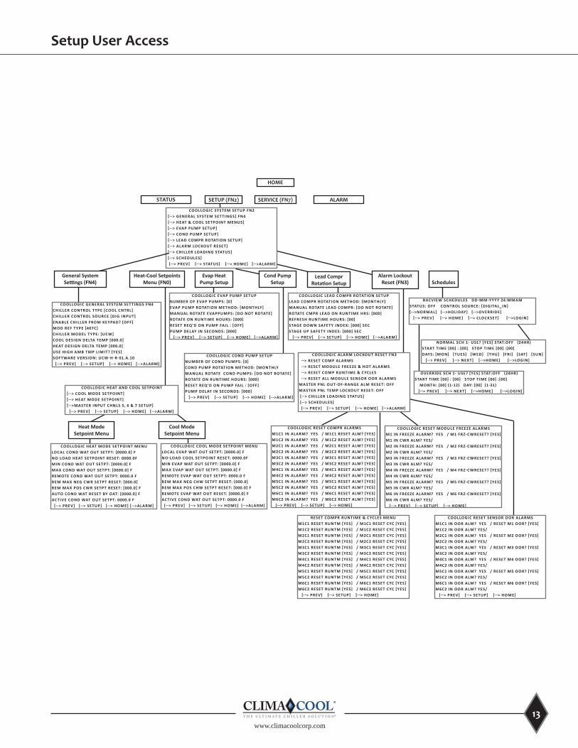
COOLLOGIC SYSTEM SETUP FN2 [--> GENERAL SYSTEM SETTINGS] FN4 [--> HEAT & COOL SETPOINT MENUS] [--> EVAP PUMP SETUP] [--> COND PUMP SETUP] [--> LEAD COMPR ROTATION SETUP] [--> ALARM LOCKOUT RESET] [--> CHILLER LOADING STATUS] [--> SCHEDULES] [--> PREV] [--> STATUS] [--> HOME] [-->ALARM]
Setup User Access
Alarm Lockout Reset (FN3)
Cond Pump Setup
Heat-Cool Setpoints Menu (FN0)
General System Settings (FN4)
SERVICE (FN7)STATUS SETUP (FN2)
HOME
ALARM
COOLLOGIC COOL MODE SETPOINT MENULOCAL EVAP WAT OUT SETPT: [0000.0] FNO-LOAD COOL SETPOINT RESET: 0000.0FMIN EVAP WAT OUT SETPT: [0000.0] FMAX EVAP WAT OUT SETPT: [0000.0] FREMOTE EVAP WAT OUT SETPT: 0000.0 FREM MAX NEG CHW SETPT RESET: [000.0]REM MAX POS CHW SETPT RESET: [000.0] FREMOTE EVAP WAT OUT RESET: [0000.0] FACTIVE COND WAT OUT SETPT: 0000.0 F [--> PREV] [--> SETUP] [--> HOME] [-->ALARM]
COOLLOGIC HEAT MODE SETPOINT MENULOCAL COND WAT OUT SETPT: [0000.0] FNO-LOAD HEAT SETPOINT RESET: 0000.0FMIN COND WAT OUT SETPT: [0000.0] FMAX COND WAT OUT SETPT: [0000.0] FREMOTE COND WAT OUT SETPT: 0000.0 FREM MAX NEG CWR SETPT RESET: [000.0]REM MAX POS CWR SETPT RESET: [000.0] FAUTO COND WAT RESET BY OAT: [0000.0] FACTIVE COND WAT OUT SETPT: 0000.0 F [--> PREV] [--> SETUP] [--> HOME] [-->ALARM]
RESET COMPR RUNTIME & CYCLES MENUM1C1 RESET RUNTM [YES] / M1C1 RESET CYC [YES]M1C2 RESET RUNTM [YES] / M1C2 RESET CYC [YES]M2C1 RESET RUNTM [YES] / M2C1 RESET CYC [YES]M2C2 RESET RUNTM [YES] / M2C2 RESET CYC [YES]M3C1 RESET RUNTM [YES] / M3C1 RESET CYC [YES]M3C2 RESET RUNTM [YES] / M3C2 RESET CYC [YES]M4C1 RESET RUNTM [YES] / M4C1 RESET CYC [YES]M4C2 RESET RUNTM [YES] / M4C2 RESET CYC [YES]M5C1 RESET RUNTM [YES] / M5C1 RESET CYC [YES]M5C2 RESET RUNTM [YES] / M5C2 RESET CYC [YES]M6C1 RESET RUNTM [YES] / M6C1 RESET CYC [YES]M6C2 RESET RUNTM [YES] / M6C2 RESET CYC [YES] [--> PREV] [--> SETUP] [--> HOME]
COOLLOGIC RESET SENSOR OOR ALARMSM1C1 IN OOR ALM? YES / RESET M1 OOR? [YES]M1C2 IN OOR ALM? YES/M2C1 IN OOR ALM? YES / RESET M2 OOR? [YES]M2C2 IN OOR ALM? YES/M3C1 IN OOR ALM? YES / RESET M3 OOR? [YES]M3C2 IN OOR ALM? YES/M4C1 IN OOR ALM? YES / RESET M4 OOR? [YES]M4C2 IN OOR ALM? YES/M5C1 IN OOR ALM? YES / RESET M5 OOR? [YES]M5C2 IN OOR ALM? YES/M6C1 IN OOR ALM? YES / RESET M6 OOR? [YES]M6C2 IN OOR ALM? YES/ [--> PREV] [--> SETUP] [--> HOME]
COOLLOGIC GENERAL SYSTEM SETTINGS FN4CHILLER CONTROL TYPE [COOL CNTRL]CHILLER CONTROL SOURCE [DIG INPUT]ENABLE CHILLER FROM KEYPAD? [OFF]MOD REF TYPE [407C]CHILLER MODEL TYPE: [UCW]COOL DESIGN DELTA TEMP [000.0]HEAT DESIGN DELTA TEMP [000.0]USE HIGH AMB TMP LIMIT? [YES]SOFTWARE VERSION: UCW-H-R-01.A.10 [--> PREV] [--> SETUP] [--> HOME] [-->ALARM]
COOLLOGIC EVAP PUMP SETUPNUMBER OF EVAP PUMPS: [0]EVAP PUMP ROTATION METHOD: [MONTHLY]MANUAL ROTATE EVAPPUMPS: [DO NOT ROTATE]ROTATE ON RUNTIME HOURS: [000]RESET REQ’D ON PUMP FAIL : [OFF]PUMP DELAY IN SECONDS: [000] [--> PREV] [--> SETUP] [--> HOME] [-->ALARM]
COOLLOGIC LEAD COMPR ROTATION SETUPLEAD COMPR ROTATION METHOD: [MONTHLY]MANUAL ROTATE LEAD COMPR: [DO NOT ROTATE]ROTATE CMPR LEAD ON RUNTIME HRS: [000]REFRESH RUNTIME HOURS: [00]STAGE DOWN SAFETY INDEX: [000] SECSTAGE UP SAFETY INDES: [000] SEC [--> PREV] [--> SETUP] [--> HOME] [-->ALARM]
BACVIEW SCHEDULES DD-MM-YYYY 24:MMAMSTATUS: OFF CONTROL SOURCE: [DIGITAL_IN][-->NORMAL] [-->HOLIDAY] [-->OVERRIDE] [--> PREV] [--> HOME] [--> CLOCKSET] [-->LOGIN]
NORMAL SCH 1- USE? [YES] STAT:OFF (24HR)START TIME [00] : [00] STOP TIME [00] :[00]DAYS: [MON] [TUES] [WED] [THU] [FRI] [SAT] [SUN] [--> PREV] [--> NEXT] [-->HOME] [-->LOGIN]
OVERRIDE SCH 1- USE? [YES] STAT:OFF (24HR)START TIME [00] : [00] STOP TIME [00] :[00] MONTH: [00] (1-12) DAY: [00] (1-31) [--> PREV] [--> NEXT] [-->HOME] [-->LOGIN]
COOLLOGIC ALARM LOCKOUT RESET FN3 --> RESET COMP ALARMS --> RESET MODULE FREEZE & HOT ALARMS --> RESET COMP RUNTIME & CYCLES --> RESET ALL MODULE SENSOR OOR ALARMSMASTER PNL OUT-OF-RANGE ALM RESET: OFFMASTER PNL TEMP LOCKOUT RESET: OFF [--> CHILLER LOADING STATUS] [--> SCHEDULES] [--> PREV] [--> SETUP] [--> HOME] [-->ALARM]
COOLLOGIC COND PUMP SETUPNUMBER OF COND PUMPS: [0]COND PUMP ROTATION METHOD: [MONTHLYMANUAL ROTATE COND PUMPS: [DO NOT ROTATE]ROTATE ON RUNTIME HOURS: [000]RESET REQ’D ON PUMP FAIL : [OFF]PUMP DELAY IN SECONDS: [000] [--> PREV] [--> SETUP] [--> HOME] [-->ALARM]
COOLLOGIC RESET COMPR ALARMSM1C1 IN ALARM? YES / M1C1 RESET ALM? [YES]M1C2 IN ALARM? YES / M1C2 RESET ALM? [YES]M2C1 IN ALARM? YES / M2C1 RESET ALM? [YES]M2C2 IN ALARM? YES / M2C2 RESET ALM? [YES]M3C1 IN ALARM? YES / M3C1 RESET ALM? [YES]M3C2 IN ALARM? YES / M3C2 RESET ALM? [YES]M4C1 IN ALARM? YES / M4C1 RESET ALM? [YES]M4C2 IN ALARM? YES / M4C2 RESET ALM? [YES]M5C1 IN ALARM? YES / M5C1 RESET ALM? [YES]M5C2 IN ALARM? YES / M5C2 RESET ALM? [YES]M6C1 IN ALARM? YES / M6C1 RESET ALM? [YES]M6C2 IN ALARM? YES / M6C2 RESET ALM? [YES] [--> PREV] [--> SETUP] [--> HOME]
COOLLOGIC RESET MODULE FREEZE ALARMSM1 IN FREEZE ALARM? YES / M1 FRZ-CWRESET? [YES]M1 IN CWR ALM? YES/M2 IN FREEZE ALARM? YES / M2 FRZ-CWRESET? [YES]M2 IN CWR ALM? YES/M3 IN FREEZE ALARM? YES / M3 FRZ-CWRESET? [YES]M3 IN CWR ALM? YES/M4 IN FREEZE ALARM? YES / M4 FRZ-CWRESET? [YES]M4 IN CWR ALM? YES/M5 IN FREEZE ALARM? YES / M5 FRZ-CWRESET? [YES]M5 IN CWR ALM? YES/M6 IN FREEZE ALARM? YES / M6 FRZ-CWRESET? [YES]M6 IN CWR ALM? YES/ [--> PREV] [--> SETUP] [--> HOME]
Schedules
COOLLOGIC HEAT AND COOL SETPOINT [--> COOL MODE SETPOINT] [--> HEAT MODE SETPOINT] [-->MASTER INPUT CHNLS 5, 6 & 7 SETUP] [--> PREV] [--> SETUP] [--> HOME] [-->ALARM]
Evap Heat Pump Setup
Lead Compr Rotation Setup
Cool Mode Setpoint Menu
Heat Mode Setpoint Menu

®
®
www.climacoolcorp.com14
COOLLOGIC SERVICE MENU SETUP FN 7[--> DIAGNOSTICS MANUAL MODE][--> ALL MODULE COMPR UNLOAD STATUS] FN5[--> ALL MODULES SENSOR CALIBRATION MENU][--> RESET ALL MODULE SENSOR OOR ALARMS][--> RESET COMP ALARMS & ALM DELAYS][--> MODULE WATER TEMP LIMITS][--> WATER & AIR TEMP LIMITS][--> CALIBRATE WATER TEMPS][--> LOCK WATER & AIR TEMPS][--> RESET COMP RUNTIMES & CYCLES] [--> PREV] [--> SETUP] [--> HOME] [-->ALARM]
COOLLOGIC RESET SENSOR OOR ALARMSM1C1 INOOR ALM? YES/RESET M1 OOR? [YES]M1C2 INOOR ALM? YES/M2C1 INOOR ALM? YES/RESET M2 OOR? [YES]M2C2 INOOR ALM? YES/M3C1 INOOR ALM? YES/RESET M3 OOR? [YES]M3C2 INOOR ALM? YES/M4C1 INOOR ALM? YES/RESET M4 OOR? [YES]M4C2 INOOR ALM? YES/M5C1 INOOR ALM? YES/RESET M5 OOR? [YES]M5C2 INOOR ALM? YES/M6C1 INOOR ALM? YES/RESET M6 OOR? [YES]M6C2 INOOR ALM? YES/ [--> PREV] [--> SETUP] [--> HOME]
MAIN HEADER WATER & AIR TEMP LIMITSEVAP WAT IN LO LIMIT : [0000.0] FEVAP WAT IN HI L IMIT : [0000.0] FEVAP WAT OUT LO LIMIT : [0000.0] FEVAP WAT OUT HI L IMIT : [0000.0] FCOND WAT IN LO LIMIT : [0000.0] FCOND WAT IN HI L IMIT : [0000.0] FCOND WAT OUT LO LIMIT : [0000.0] FCOND WAT OUT HI L IMIT : [0000.0] FUSE HI AMB TEMP LIMIT? : [YES]OUTDOOR AIR LO LIMIT : [0000.0] FOUTDOOR AIR HI L IMIT : [0000.0] FM6C2 INOOR ALM? YES/ [--> PREV] [--> SETUP] [--> HOME]
EVAP WAT IN LOCK : [OFF]EVAP WAT IN LOCK VALUE : [0000.0] FEVAP WAT OUT LO LOCK : [OFF]EVAP WAT OUT HI LOCK VALUE : [0000.0] FCOND WAT IN LOCK : [OFF]COND WAT IN LOCK VALUE : [0000.0] FCOND WAT OUT LOCK : [OFF]COND WAT OUT LOCK VALUE : [0000.0] FOUTDOOR AIR LOCK : [OFF]OUTDOOR AIR LOCK VALUE : [0000.0] F [--> PREV] [--> SETUP] [--> HOME]
COOLLOGIC RESET COMPR ALARMSM1C1 IN ALARM? YES / M1C1RESET ALM? [YES]M1C2 IN ALARM? YES / M1C2RESET ALM? [YES]M2C1 IN ALARM? YES / M2C1RESET ALM? [YES]M2C2 IN ALARM? YES / M2C2RESET ALM? [YES]M3C1 IN ALARM? YES / M3C1RESET ALM? [YES]M3C2 IN ALARM? YES / M3C2RESET ALM? [YES]M4C1 IN ALARM? YES / M4C1RESET ALM? [YES]M4C2 IN ALARM? YES / M4C2RESET ALM? [YES]M5C1 IN ALARM? YES / M5C1RESET ALM? [YES]M5C2 IN ALARM? YES / M5C2RESET ALM? [YES]M6C1 IN ALARM? YES / M6C1RESET ALM? [YES]M6C2 IN ALARM? YES / M6C2RESET ALM? [YES] [--> PREV] [--> SETUP] [--> HOME]
COOLLOGIC ALL MODULE COMPR UNLOADS FN5[ --> MODULE 1 COMPR UNLOAD STATUS][ --> MODULE 2 COMPR UNLOAD STATUS][ --> MODULE 3 COMPR UNLOAD STATUS][ --> MODULE 4 COMPR UNLOAD STATUS][ --> MODULE 5 COMPR UNLOAD STATUS][ --> MODULE 6 COMPR UNLOAD STATUS] [--> PREV] [--> SETUP] [--> HOME] [-->ALARM]
[ --> MANUAL MODE M1] / [--> MANUAL MODE M2] [ --> MANUAL MODE M3] / [--> MANUAL MODE M4] [ --> MANUAL MODE M5] / [--> MANUAL MODE M6] / [--> LOCK WATER TEMPS] SWAP LEAD COMPR: [DO NOT REFRESH LEAD][ --> MODULE 6 COMPR UNLOAD STATUS] [--> PREV] [--> SETUP] [--> HOME] [-->ALARM]
M1 MANUAL MODE [OFF]M1C1 MANUAL ON [OFF] M1C2 STATUS: OFFM1C2 MANUAL ON [OFF] M1C2 STATUS: OFF [--> PREV] [--> SERVICE] [--> HOME]
M2 MANUAL MODE [OFF]M2C1 MANUAL ON [OFF] M2C2 STATUS: OFFM2C2 MANUAL ON [OFF] M2C2 STATUS: OFF [--> PREV] [--> SERVICE] [--> HOME]
CALIBRATE MAIN HEATER WATER & AIR TEMPSEVAP INSENS: 0000.0F / EVAP WAT IN: 0000.0F EVAP IN CALIB OFFSET : [0000.0]FEVAP OUTSENS: 0000.0F / EVAP WATOUT: 0000.0F EVAP OUT CALIB OFFSET : [0000.0]FCND OUT SENS: 0000.0F / CNDWAT OUT: 0000.0FCOND OUT CALIB OFFSET : [0000.0]FCOND IN SENS: 0000.0F / CND WAT IN: 0000.0FCOND IN CALIB OFFSET : [0000.0]FOUTDOOR SENS: 0000.0F / OUTDR AIR: 0000.0F OUTDOOR AIR CALIB OFFSET: [0000.0]F [--> PREV] [--> SETUP] [--> HOME]
COOLLOGIC MODULE 1 COMPR UNLOAD STATUSM1C1 LOW SUCT PRESS UNLOAD :[OFF]M1C2 LOW SUCT PRESS UNLOAD :[OFF]M1C1 LOW SUCT TEMP UNLOAD :[OFF]M1C2 LOW SUCT TEMP UNLOAD :[OFF]M1 EVAP FREEZE TEMP UNLOAD :[OFF]M1 COND WATOUT TEMP UNLOAD :[OFF]M1C1 HIGH DIS PRESS UNLOAD :[OFF]M1C2 HIGH DIS PRESS UNLOAD :[OFF]M1C1 HIGH DIS TEMP UNLOAD :[OFF]M1C2 HIGH DIS TEMP UNLOAD :[OFF] [--> PREV] [--> SETUP] [--> HOME] [--> ALARM]
CLIMACOOL MODULE 1 WATER CALIBRATIONSEVP OUT CALIB: [0000.0]F / EVP OUT STA: 0000.0FCOND OUT CALIB: [0000.0]F / COND OUT STAT: 0000.0F
CLIMACOOL MODULE 1 REFRIG CALIBRATIONSC1 DIS PRES CAL: [0000]PSI / C1 DIS PR: 0000PSIC2 DIS PRES CAL: [0000]PSI / C2 DIS PR: 0000PSIC1 SUC PRES CAL: [0000]F O / C1 SUC PR: 0000F O
C2 SUC PRES CAL: [0000]F O/ C2 SUC PR: 0000F O
C1 DIS TMP CAL: [0000]F O/ C1 DIS TP: 0000F O
C2 DIS TMP CAL: [0000]F O/ C2 DIS TP: 0000F O
C1 SUC TEMP CAL: [0000]F O / C1 SUC TP: 0000F O
C2 SUC TEMP CAL: [0000]F O/ C2 SUC TP: 0000F O
[--> PREV] [--> SETUP] [--> HOME]
Service User Access
Main Hdr Water Temp Limits
Module Water Temp Limits
Reset Compr Alarms
Calibrate ALL Module Sensors
Module Compr Unload Functions F5
Diagnostic & Manual Mode
Lock Water Temps
Calib. Main Hdr Water Temps
SERVICE (FN7)STATUS SETUP (FN2)
HOME
ALARM

15®
®
www.climacoolcorp.com
Connection TypeThe default CONNECTION TYPE for the BACnet over ETHERNET to the WEB PORTAL is a CAT5 Cable via an RJ-45 connector . The connector plugs into the Ethernet 10BaseT port .
Ethernet NetworkThe Master Controller is equipped with an interface which may be connected directly to the Ethernet network using the 10BaseT port . To prevent circular routes, the Master Panel will be configured only for BACnet/IP. The BACnet/IP Network Number will be defaulted to 516800 . The BACnet/Ethernet router configuration will be disabled and the Ethernet Network number set to 0 . Note: If these settings need to be changed, please contact a ClimaCool Representative .
IP AddressThe following is the default settings for the IP Address for a typical Master Controller:IP .............................................192.168.17.100 Subnet Mask...........................255.255.255.0Gateway ..................................192.168.17.1
Note: If these settings need to be changed, please contact a ClimaCool Representative .
Device Instance of Master ControllerThe device instance number for the Master Controller is 516800 . The “address” number of the Master is “01,” as identified by the two rotary switches on the Master PCB (one rotary switch is for 10’s digit and the other is for the 1’s digit), (see Figure 3 – page 3). Note: If these settings need to be changed, please contact a ClimaCool Representative .
Device Instance of Module ControllerThe device instance number for the FIRST Module Controller is 243002 . The “address” number of the FIRST module controller is “02 .” Similarly, the device instance number of the SECOND Module Controller is 243003 . The “address” number of the SECOND Module Controller is “03 .” Note: If these settings need to be changed, please contact a ClimaCool Representative .
Note: Contact factory for network points list .
Note: The installation of two banks, with separate Master Control Panels, utilizing the same BAS network must have different device instance numbers to negate any conflicts. Contact factory for special programming requirements.
CoolLogic Control System Network Setup
®
®
www.climacoolcorp.com16
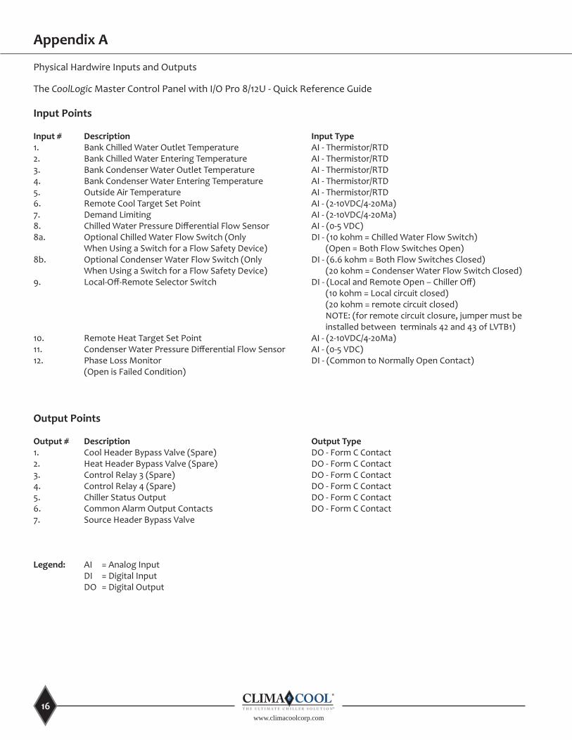
Appendix A
Physical Hardwire Inputs and Outputs
The CoolLogic Master Control Panel with I/O Pro 8/12U - Quick Reference Guide
Input Points
Input # Description Input Type1 . Bank Chilled Water Outlet Temperature AI - Thermistor/RTD2 . Bank Chilled Water Entering Temperature AI - Thermistor/RTD 3 . Bank Condenser Water Outlet Temperature AI - Thermistor/RTD4 . Bank Condenser Water Entering Temperature AI - Thermistor/RTD5 . Outside Air Temperature AI - Thermistor/RTD6. Remote Cool Target Set Point AI - (2-10VDC/4-20Ma)7. Demand Limiting AI - (2-10VDC/4-20Ma) 8. Chilled Water Pressure Differential Flow Sensor AI - (0-5 VDC)8a. Optional Chilled Water Flow Switch (Only DI - (10 kohm = Chilled Water Flow Switch) When Using a Switch for a Flow Safety Device) (Open = Both Flow Switches Open)8b. Optional Condenser Water Flow Switch (Only DI - (6.6 kohm = Both Flow Switches Closed) When Using a Switch for a Flow Safety Device) (20 kohm = Condenser Water Flow Switch Closed)9. Local-Off-Remote Selector Switch DI - (Local and Remote Open – Chiller Off) (10 kohm = Local circuit closed) (20 kohm = remote circuit closed) NOTE: (for remote circuit closure, jumper must be installed between terminals 42 and 43 of LVTB1)10. Remote Heat Target Set Point AI - (2-10VDC/4-20Ma)11. Condenser Water Pressure Differential Flow Sensor AI - (0-5 VDC)12. Phase Loss Monitor DI - (Common to Normally Open Contact) (Open is Failed Condition)
Output Points
Output # Description Output Type1. Cool Header Bypass Valve (Spare) DO - Form C Contact2. Heat Header Bypass Valve (Spare) DO - Form C Contact3. Control Relay 3 (Spare) DO - Form C Contact4. Control Relay 4 (Spare) DO - Form C Contact5 . Chiller Status Output DO - Form C Contact6 . Common Alarm Output Contacts DO - Form C Contact7 . Source Header Bypass Valve
Legend: AI = Analog Input DI = Digital Input DO = Digital Output
17®
®
www.climacoolcorp.com
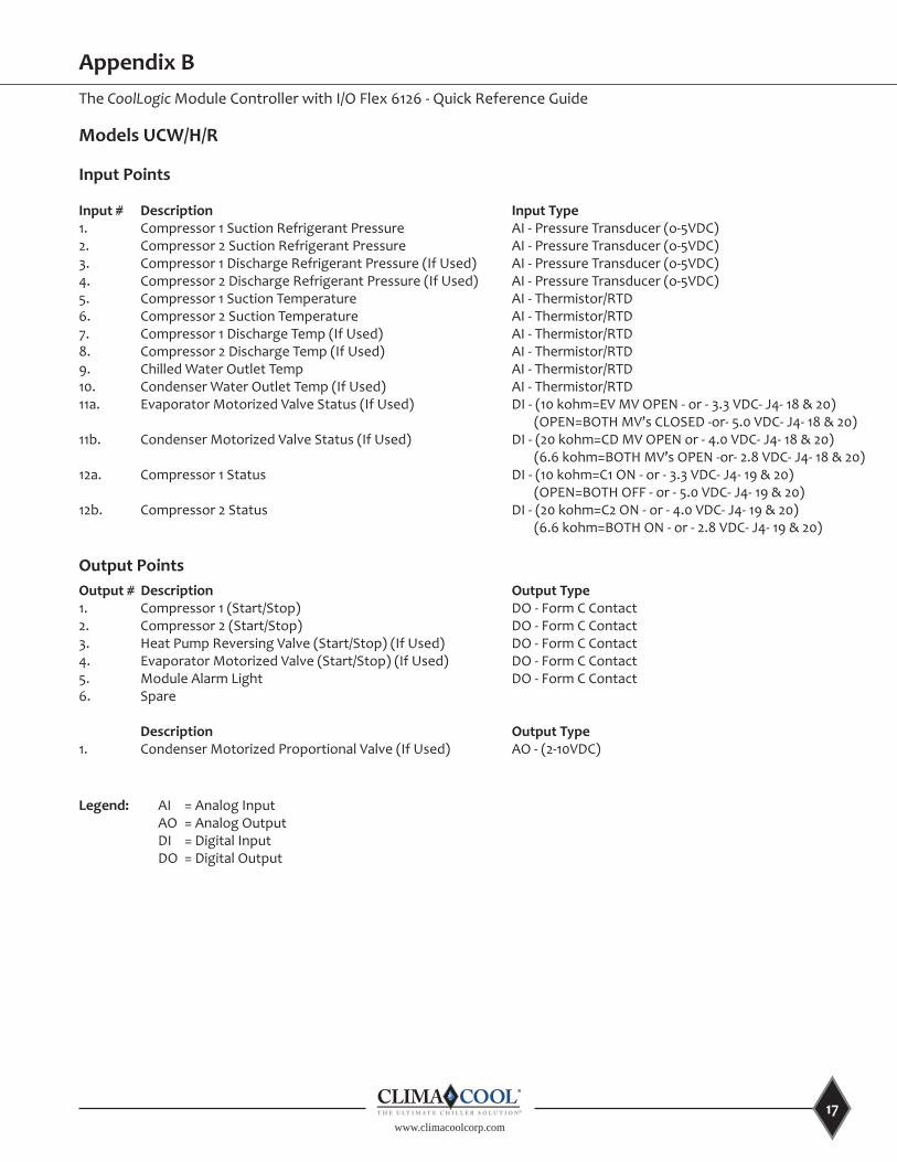
Appendix BThe CoolLogic Module Controller with I/O Flex 6126 - Quick Reference Guide
Models UCW/H/R
Input Points
Input # Description Input Type1. Compressor 1 Suction Refrigerant Pressure AI - Pressure Transducer (o-5VDC)2. Compressor 2 Suction Refrigerant Pressure AI - Pressure Transducer (o-5VDC)3. Compressor 1 Discharge Refrigerant Pressure (If Used) AI - Pressure Transducer (o-5VDC)4. Compressor 2 Discharge Refrigerant Pressure (If Used) AI - Pressure Transducer (o-5VDC)5 . Compressor 1 Suction Temperature AI - Thermistor/RTD6 . Compressor 2 Suction Temperature AI - Thermistor/RTD7. Compressor 1 Discharge Temp (If Used) AI - Thermistor/RTD8. Compressor 2 Discharge Temp (If Used) AI - Thermistor/RTD9 . Chilled Water Outlet Temp AI - Thermistor/RTD10. Condenser Water Outlet Temp (If Used) AI - Thermistor/RTD11a. Evaporator Motorized Valve Status (If Used) DI - (10 kohm=EV MV OPEN - or - 3.3 VDC- J4- 18 & 20) (OPEN=BOTH MV’s CLOSED -or- 5.0 VDC- J4- 18 & 20)11b. Condenser Motorized Valve Status (If Used) DI - (20 kohm=CD MV OPEN or - 4.0 VDC- J4- 18 & 20) (6.6 kohm=BOTH MV’s OPEN -or- 2.8 VDC- J4- 18 & 20)12a. Compressor 1 Status DI - (10 kohm=C1 ON - or - 3.3 VDC- J4- 19 & 20) (OPEN=BOTH OFF - or - 5.0 VDC- J4- 19 & 20) 12b. Compressor 2 Status DI - (20 kohm=C2 ON - or - 4.0 VDC- J4- 19 & 20) (6.6 kohm=BOTH ON - or - 2.8 VDC- J4- 19 & 20)
Output Points Output # Description Output Type1. Compressor 1 (Start/Stop) DO - Form C Contact2. Compressor 2 (Start/Stop) DO - Form C Contact3. Heat Pump Reversing Valve (Start/Stop) (If Used) DO - Form C Contact4. Evaporator Motorized Valve (Start/Stop) (If Used) DO - Form C Contact5 . Module Alarm Light DO - Form C Contact6 . Spare
Description Output Type1. Condenser Motorized Proportional Valve (If Used) AO - (2-10VDC)
Legend: AI = Analog Input AO = Analog Output DI = Digital Input DO = Digital Output
®
®
www.climacoolcorp.com18
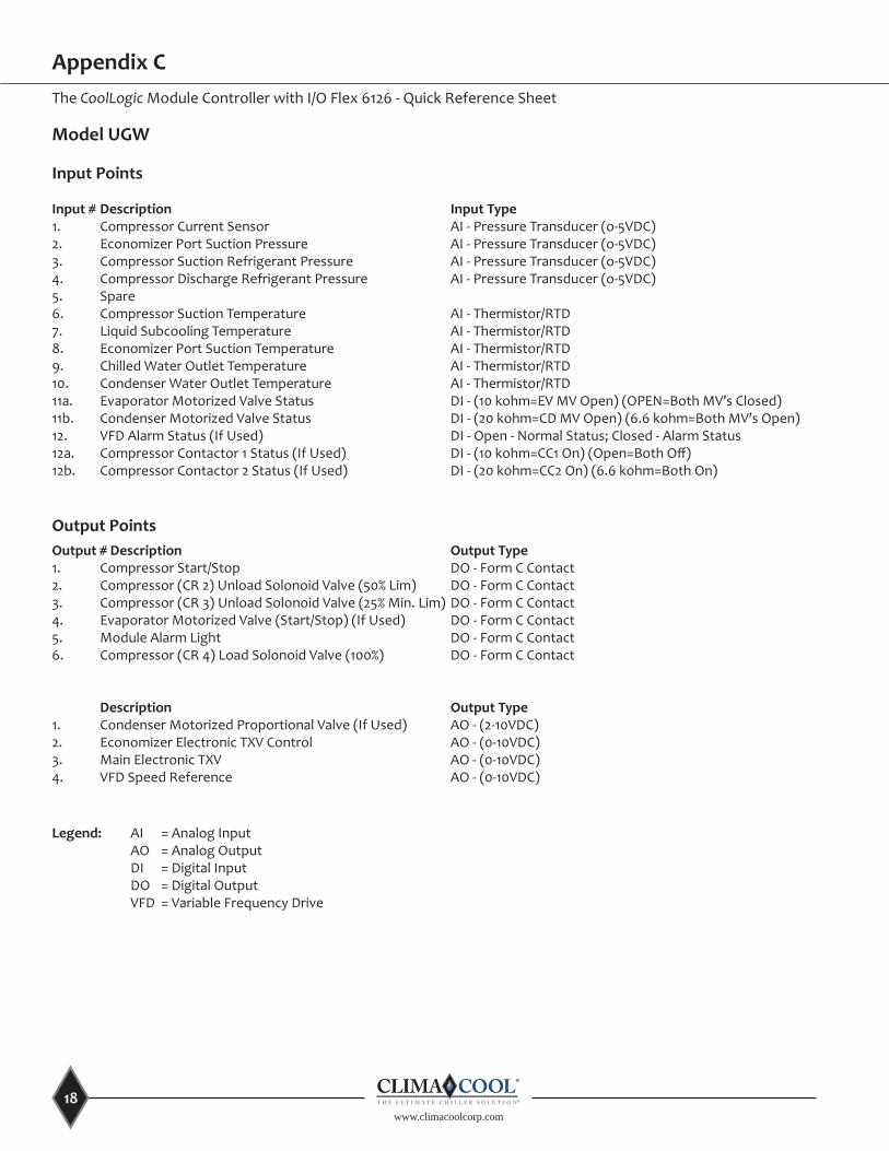
Appendix CThe CoolLogic Module Controller with I/O Flex 6126 - Quick Reference Sheet
Model UGW
Input Points
Input # Description Input Type1. Compressor Current Sensor AI - Pressure Transducer (o-5VDC)2. Economizer Port Suction Pressure AI - Pressure Transducer (o-5VDC)3. Compressor Suction Refrigerant Pressure AI - Pressure Transducer (o-5VDC)4. Compressor Discharge Refrigerant Pressure AI - Pressure Transducer (o-5VDC)5 . Spare 6 . Compressor Suction Temperature AI - Thermistor/RTD7 . Liquid Subcooling Temperature AI - Thermistor/RTD8 . Economizer Port Suction Temperature AI - Thermistor/RTD9 . Chilled Water Outlet Temperature AI - Thermistor/RTD10 . Condenser Water Outlet Temperature AI - Thermistor/RTD11a. Evaporator Motorized Valve Status DI - (10 kohm=EV MV Open) (OPEN=Both MV’s Closed)11b. Condenser Motorized Valve Status DI - (20 kohm=CD MV Open) (6.6 kohm=Both MV’s Open)12. VFD Alarm Status (If Used) DI - Open - Normal Status; Closed - Alarm Status12a. Compressor Contactor 1 Status (If Used) DI - (10 kohm=CC1 On) (Open=Both Off)12b. Compressor Contactor 2 Status (If Used) DI - (20 kohm=CC2 On) (6.6 kohm=Both On)
Output Points Output # Description Output Type1 . Compressor Start/Stop DO - Form C Contact2. Compressor (CR 2) Unload Solonoid Valve (50% Lim) DO - Form C Contact3. Compressor (CR 3) Unload Solonoid Valve (25% Min. Lim) DO - Form C Contact4. Evaporator Motorized Valve (Start/Stop) (If Used) DO - Form C Contact5 . Module Alarm Light DO - Form C Contact6. Compressor (CR 4) Load Solonoid Valve (100%) DO - Form C Contact
Description Output Type1. Condenser Motorized Proportional Valve (If Used) AO - (2-10VDC)2. Economizer Electronic TXV Control AO - (0-10VDC)3. Main Electronic TXV AO - (0-10VDC)4. VFD Speed Reference AO - (0-10VDC)
Legend: AI = Analog Input AO = Analog Output DI = Digital Input DO = Digital Output VFD = Variable Frequency Drive
19®
®
www.climacoolcorp.com
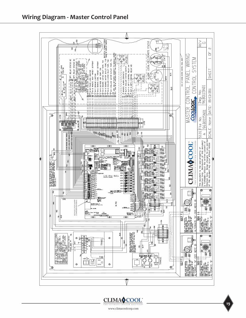
Wiring Diagram - Master Control Panel

®
®
www.climacoolcorp.com20
Wiring Diagram - Master Control Panel

21®
®
www.climacoolcorp.com
Wiring Diagram - SHC Expander Board
®
®
www.climacoolcorp.com22
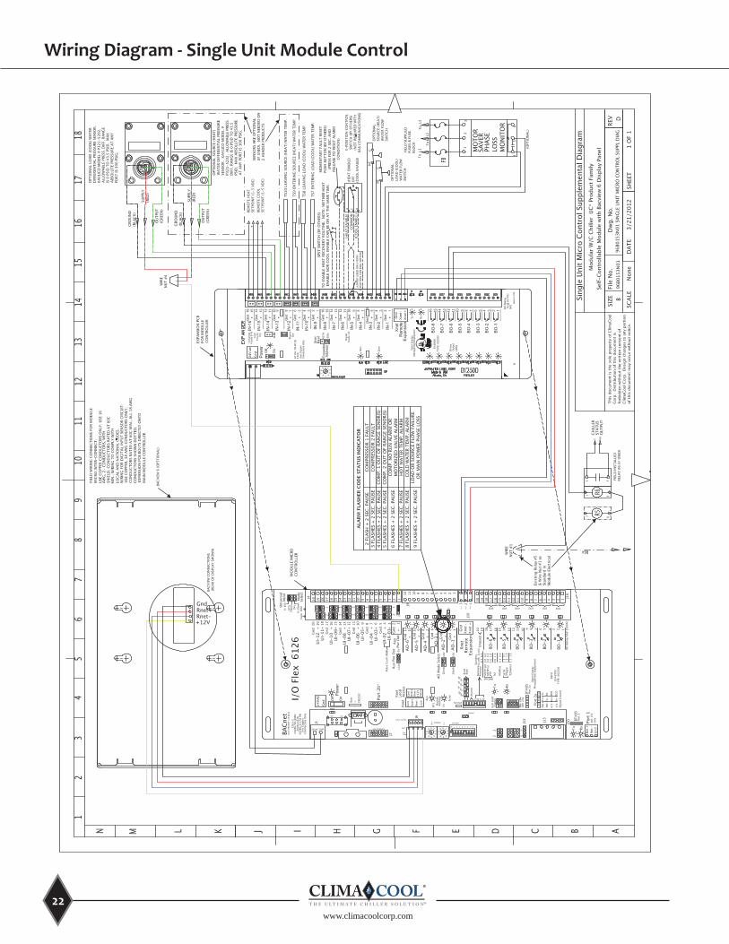
Wiring Diagram - Single Unit Module Control

23®
®
www.climacoolcorp.com
Wiring Diagram - Voltage/Phase Monitor

®
®
www.climacoolcorp.com24
Warranty Certificate
forms\ccool\standard form
s\word files\C
Cool w
arranty compressor certificate 07-17-14
W
AR
RA
NT
Y D
ISCL
AIM
ER
It is expressly understood that unless a statem
ent is specifically identified as a warranty, statem
ents made by C
limaC
ool Corp., an O
klahoma corporation (“C
C”), or its representatives, relating to C
C’s products, w
hether oral, written or contained in any
quote, sales literature, catalog or any agreement, are not express w
arranties and do not form a part of the basis of the bargain, but are m
erely CC
’s opinion or comm
endation of CC
’s products. EX
CE
PT A
S SPEC
IFICA
LL
Y SE
T FO
RT
H H
ER
EIN
, T
HE
RE
IS NO
EX
PRE
SS WA
RR
AN
TY
AS T
O A
NY
OF C
C’S PR
OD
UC
TS. C
C M
AK
ES N
O W
AR
RA
NT
Y A
GA
INST
LA
TE
NT
DE
FEC
TS. C
C M
AK
ES N
O W
AR
RA
NT
Y O
F ME
RC
HA
NT
AB
ILITY
OF T
HE
GO
OD
S OR
OF T
HE
FIT
NE
SS OF T
HE
GO
OD
S FOR
AN
Y PA
RT
ICU
LA
R PU
RPO
SE.
G
RA
NT
OF L
IMIT
ED
EX
PRE
SS WA
RR
AN
TY
C
C w
arrants CC
’s products purchased and retained in the United States of A
merica and C
anada to be free from defects in m
aterial and workm
anship under normal use and m
aintenance only as follows:
FOR
MO
DU
LA
R C
HIL
LE
RS: (a) A
ll modular chillers built or sold by C
C for tw
elve (12) months from
the date of unit start-up or eighteen (18) months from
date of shipment (from
CC
’s warehouse), w
hichever comes first; and (b) A
ny repair and replacem
ent parts, which are not supplied under w
arranty, for ninety (90) days from date of shipm
ent (from C
C’s w
arehouse) and (c) If such extended warranty is purchased, the com
pressors in all modular chillers built or sold by C
C shall extend for
sixty (60) months from
the date of shipment (from
CC
’s warehouse).
FOR
RO
OF T
OP U
NIT
S: (a) All roof top units built or sold by C
C for tw
elve (12) months from
the date of unit start-up or eighteen (18) months from
date of shipment (from
CC
’s warehouse), w
hichever comes first; (b) A
ll compressors supplied by
CC
with C
C’s roof top units for sixty (60) m
onths from date of shipm
ent (from C
C’s w
arehouse); (c) All gas fired stainless steel heat exchangers supplied by C
C w
ith CC
’s roof top units for ten (10) years from date of shipm
ent (from C
C’s w
arehouse); and (d) A
ny repair and replacement parts, w
hich are not supplied under warranty, for ninety (90) days from
date of shipment (from
CC
’s warehouse).
All parts m
ust be returned to CC
’s warehouse in O
klahoma C
ity, Oklahom
a, freight prepaid, no later than sixty (60) days after the date of the failure of the part. If CC
determines the part to be defective and w
ithin CC
’s Limited Express W
arranty, CC
shall, w
hen such part has been either replaced or repaired, return such to a CC
recognized dealer, contractor or service organization, F.O.B. C
C’s w
arehouse, Oklahom
a City, O
klahoma, freight prepaid. The w
arranty on any part repaired or replaced under w
arranty expires at the end of the original warranty period.
This warranty does not cover and does not apply to: (1) Fuses, refrigerant, fluids, oil; (2) Products relocated after initial installation; (3) A
ny portion or component of the system
that is not supplied by CC
, regardless of the cause of the failure of such portion or com
ponent; (4) Products on which the units identification tags or labels have been rem
oved or defaced; (5) Products on which paym
ent to CC
is or has been in default; (6) Products which have defects or dam
age which result from
improper
installation, wiring, electrical im
balance characteristics or maintenance (including, w
ithout limitation, defects or dam
ages caused by voltage surges, inadequate voltage conditions, phase imbalance, any form
of electrical disturbances, inadequate or im
proper electrical circuit installation or protection, failure to perform com
mon m
aintenance, etc.); or are caused by accident, misuse or abuse, fire, flood, alteration or m
isapplication of the product; (7) Products which have defects or dam
age which
result from a contam
inated or corrosive air or liquid supply, operation at abnormal tem
peratures, or unauthorized opening of refrigerant circuit; (8) Products subjected to corrosion or abrasion or chemicals; (9) M
old, fungus or bacteria damage; (10)
Products manufactured or supplied by others; (11) Products w
hich have been subjected to misuse, negligence or accidents; (12) Products w
hich have been operated in a manner contrary to C
C’s printed instructions; (13) Products w
hich have defects, dam
age or insufficient performance as a result of insufficient or incorrect system
design or the improper application of C
C’s products; (14) Products w
hich have defects or damages due to freezing of the w
ater supply, an inadequate or interrupted water
supply, corrosives or abrasives in the water supply, or im
proper or inadequate filtration or treatment of the w
ater or air supply: (15) Products which are defects caused by overfiring, use of incorrect fuel, or im
proper burn or control adjustments; or (16)
Products which have incom
plete or inadequate combustion.
CC
is not responsible for: (1) The costs of any fluids, refrigerant or other system com
ponents, or the associated labor to repair or replace the same, w
hich is incurred as a result of a defective part covered by CC
’s Limited Express W
arranty; (2) The costs of labor, refrigerant, m
aterials or service incurred in removal of the defective part, or in obtaining and replacing the new
or repaired part; or, (3) Transportation costs of the defective part from the installation site to C
C or the return of any part not covered
by CC
’s Limited Express W
arranty. L
imitation: This Lim
ited Express Warranty is given in lieu of all other w
arranties. If, notwithstanding the disclaim
ers contained herein, it is determined that other w
arranties exist, any such warranty, including w
ithout limitation, any express w
arranties or any im
plied warranties of fitness for any particular purpose and m
erchantability, shall be limited to the duration of the Lim
ited Express Warranty.
LIM
ITA
TIO
N O
F REM
ED
IES
In the event of a breach of this Limited Express W
arranty, CC
will only be obligated at C
C’s option to repair the failed part or m
odule or to furnish a new or rebuilt part or m
odule in exchange for the part or module w
hich has failed. If, after written
notice to CC
’s Head O
ffice in Oklahom
a City, O
klahoma of each defect, m
alfunction or other failure and a reasonable number of attem
pts by CC
to correct the defect, malfunction or other failure and the rem
edy fails of its essential purpose, CC
shall refund the purchase price paid to C
C in exchange for the return of the sold good(s). Said refund shall be the m
aximum
liability of CC
. TH
IS RE
ME
DY
IS TH
E SO
LE
AN
D E
XC
LU
SIVE
RE
ME
DY
AG
AIN
ST C
C FO
R B
RE
AC
H O
F C
ON
TR
AC
T, FO
R T
HE
BR
EA
CH
OF A
NY
WA
RR
AN
TY
OR
FOR
CC
’S OW
N N
EG
LIG
EN
CE
OR
IN ST
RIC
T L
IABIL
ITY
. L
IMIT
AT
ION
OF LIA
BIL
ITY
C
C shall have no liability for any dam
ages if CC
’s performance is delayed for any reason or is prevented to any extent by any event such as, but not lim
ited to any, war, civil unrest, governm
ent restrictions or restraints, strikes, or work stoppages, fire,
flood, accident, allocation, shortages of transportation, fuel, material or labor, acts of G
od or any other reason beyond the sole control of CC
. CC
EX
PRE
SSLY
DISC
LA
IMS A
ND
EX
CL
UD
ES A
NY
LIA
BILITY
FOR
CO
NSE
QU
EN
TIA
L O
R
INC
IDE
NT
AL
DA
MA
GE
IN C
ON
TR
AC
T, FO
R B
RE
AC
H O
F AN
Y E
XPR
ESS O
R IM
PLIE
D W
AR
RA
NT
Y, O
R IN
TOR
T, W
HE
TH
ER
FOR
CC
’S OW
N N
EG
LIG
EN
CE
OR
AS ST
RIC
T L
IAB
ILITY
. O
BT
AIN
ING
WA
RR
AN
TY
PER
FOR
MA
NC
E
Norm
ally, the contractor or service organization who installed the products w
ill provide warranty perform
ance for the owner. Should the installer be unavailable, contact any C
C recognized contractor or service organization. If assistance is required in
obtaining warranty perform
ance, write:
Clim
aCool C
orp. P.O. Box 2055 O
klahoma C
ity, Oklahom
a 73101 (405) 815-3000 e-mail: C
laims@
climacoolcorp.com
NO
TE: Some states or C
anadian provinces do not allow lim
itations on how long an im
plied warranty lasts, or the lim
itation or exclusion of consequential or incidental damages, so the foregoing exclusion and lim
itations may not apply to you. This
warranty gives you specific legal rights, and you m
ay also have other rights which vary from
state to state and from C
anadian province to Canadian province.
Please refer to the C
C Installation, O
peration and Maintenance M
anual for operating and maintenance instructions.
CL
IMA
CO
OL
CO
RPO
RA
TIO
N
LIM
ITE
D E
XPR
ESS W
AR
RA
NT
Y/L
IMIT
AT
ION
OF R
EM
ED
IES A
ND
LIA
BIL
ITY
W
ITH
EX
TE
ND
ED
CO
MPR
ESSO
R W
AR
RA
NT
Y

25®
®
www.climacoolcorp.com
ClimaCool works continually to improve its products. As a result, the design and specifi cations of each product at the time for order may be changed without notice and may not be as described herein. Please contact ClimaCool’s Customer Service Department at (405) 815-3000 for specifi c information on the current design and specifi cations. Statements and other information contained herein are not express warranties and do not form the basis of any bargain between the parties, but are merely ClimaCool’s opinion or commendation of its products .
‘USGBC®’ and related logo is a trademark owned by the U .S . Green Building Council® and is used with permission .
Doc# 97B0083N01 © ClimaCool Corp . 2012 Rev: 09/2014
15 S . VirginiaOklahoma City, OK 73106
Phone: 405-815-3000Fax: 405-815-3052
www .climacoolcorp .com