COOLING SYSTEM - Boat Parts, Marine Engine Parts, Boat
26
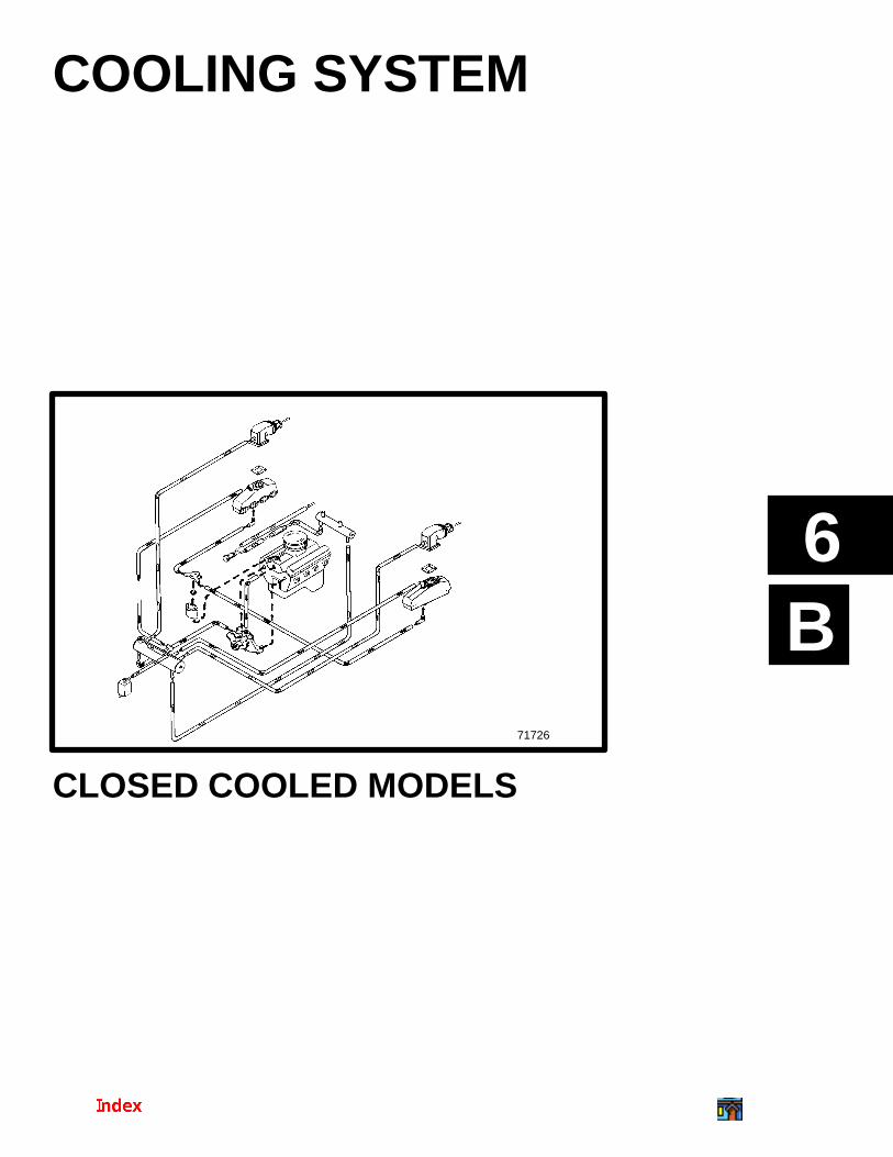
B 6 71726 COOLING SYSTEM CLOSED COOLED MODELS
Transcript of COOLING SYSTEM - Boat Parts, Marine Engine Parts, Boat
B6
71726
COOLING SYSTEM
CLOSED COOLED MODELS
6B-0 - CLOSED COOLING SYSTEMS 90-823224--2 796
Table of ContentsPage
Torque Specifications 6B-1. . . . . . . . . . . . . . . . . . . . . Lubricants/Sealants 6B-1. . . . . . . . . . . . . . . . . . . . . . Specifications 6B-1. . . . . . . . . . . . . . . . . . . . . . . . . . . .
Closed Cooling System Capacity 6B-1. . . . . . . . Thermostat 6B-1. . . . . . . . . . . . . . . . . . . . . . . . . . . Pressure Cap Rating 6B-1. . . . . . . . . . . . . . . . . . .
Description 6B-2. . . . . . . . . . . . . . . . . . . . . . . . . . . . . . Maintaining Coolant Level 6B-2. . . . . . . . . . . . . . . . . Pressure Cap Maintenance 6B-3. . . . . . . . . . . . . . . . Seawater Pickup Pump Maintenance 6B-3. . . . . . . Heat Exchanger Repair 6B-3. . . . . . . . . . . . . . . . . . . Testing Closed Cooling System 6B-4. . . . . . . . . . . .
Testing Coolant for Alkalinity 6B-4. . . . . . . . . . . . Pressure Testing System 6B-4. . . . . . . . . . . . . . . Testing for Cylinder Head Gasket Leak 6B-5. . . Testing Heat Exchanger 6B-5. . . . . . . . . . . . . . . . Testing Pressure Cap 6B-5. . . . . . . . . . . . . . . . . .
Thermostat 6B-7. . . . . . . . . . . . . . . . . . . . . . . . . . . . . . Removal 6B-7. . . . . . . . . . . . . . . . . . . . . . . . . . . . . Testing 6B-8. . . . . . . . . . . . . . . . . . . . . . . . . . . . . . . Installation 6B-9. . . . . . . . . . . . . . . . . . . . . . . . . . . .
Changing Coolant 6B-10. . . . . . . . . . . . . . . . . . . . . . . Closed Cooling Section 6B-10. . . . . . . . . . . . . . . . Coolant Recommendations 6B-10. . . . . . . . . . . . Change Intervals 6B-10. . . . . . . . . . . . . . . . . . . . . Draining Instructions 6B-10. . . . . . . . . . . . . . . . . . Draining Diagrams - Coolant Side 6B-11. . . . . . .
Cleaning System 6B-14. . . . . . . . . . . . . . . . . . . . . . . . Closed Cooling Section 6B-14. . . . . . . . . . . . . . . . Seawater Section 6B-14. . . . . . . . . . . . . . . . . . . . .
Filling Closed Cooling Section 6B-15. . . . . . . . . . . . Fresh Water Flow Thru Exhaust Manifold 6B-15Seawater Flow Thru Exhaust Manifolds 6B-16. .
Auxiliary Hot Water Heater Installation 6B-17. . . . . Recommended Supply Locations 6B-17. . . . . . . Recommended Return Locations 6B-18. . . . . . .
Closed Cooling System Flow Diagrams 6B-19. . . . MCM Bravo Models - 7.4L/454 Magnum 6B-19. MCM Model - 502 Magnum 6B-20. . . . . . . . . . . . MIE Models - 7.4L / 8.2L 6B-21. . . . . . . . . . . . . . . MIE 454 CID / 7.4L 502 CID / 8.2L with Vertical Mounted Oil Cooler / Port Side Mounted Transmission Cooler / Optional Fuel Cooler And MCM 454 CID / 7.4L Without Coolant Flow Through Exhaust Manifolds 6B-22. . . . . . . . . . . . . . . . . . . . . . . . . . .
CLOSED COOLING SYSTEMS - 6B-190-823324--2 796
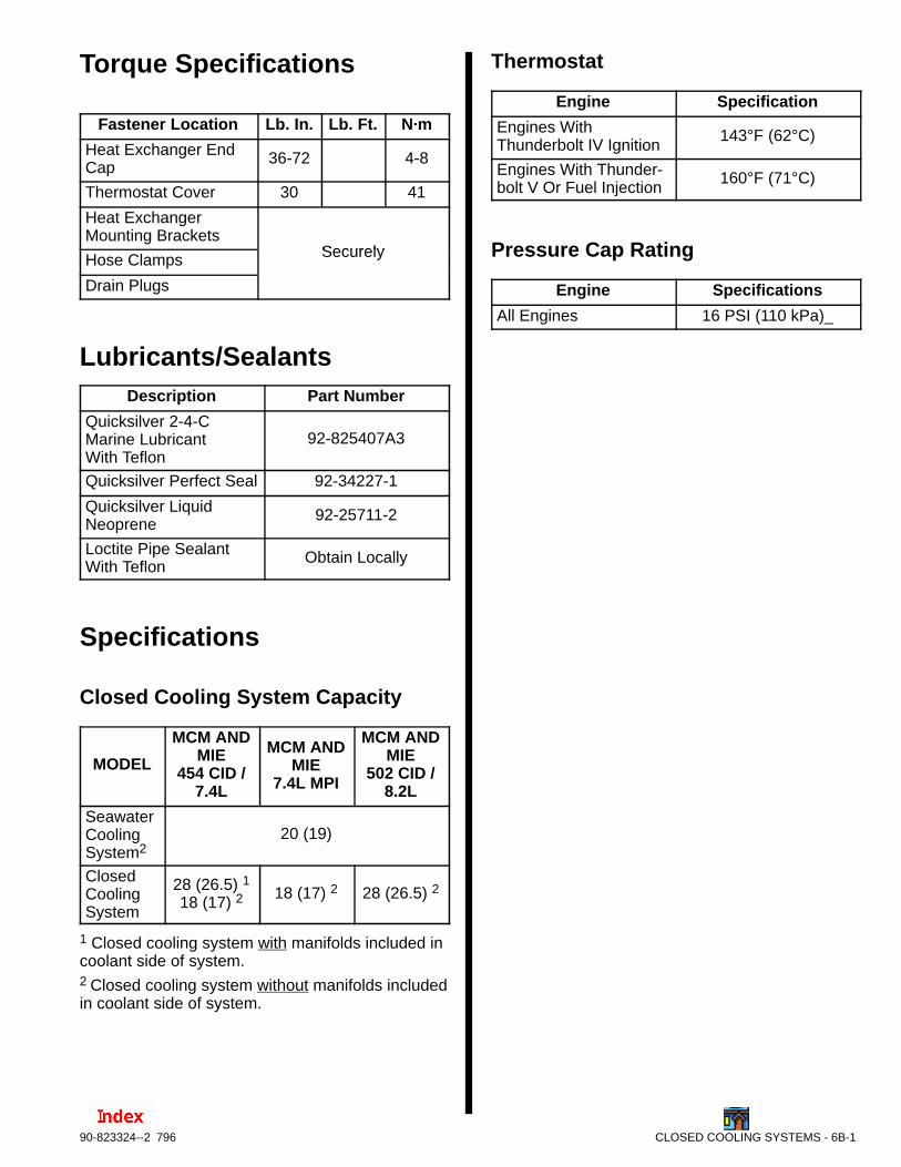
Torque Specifications
Fastener Location Lb. In. Lb. Ft. N·m
Heat Exchanger EndCap
36-72 4-8
Thermostat Cover 30 41
Heat ExchangerMounting Brackets
SecurelyHose Clamps Securely
Drain Plugs
Lubricants/SealantsDescription Part Number
Quicksilver 2-4-CMarine LubricantWith Teflon
92-825407A3
Quicksilver Perfect Seal 92-34227-1
Quicksilver Liquid Neoprene
92-25711-2
Loctite Pipe SealantWith Teflon
Obtain Locally
Specifications
Closed Cooling System Capacity
MODEL
MCM ANDMIE
454 CID /7.4L
MCM ANDMIE
7.4L MPI
MCM ANDMIE
502 CID /8.2L
SeawaterCooling System2
20 (19)
ClosedCoolingSystem
28 (26.5) 118 (17) 2
18 (17) 2 28 (26.5) 2
1 Closed cooling system with manifolds included incoolant side of system.2 Closed cooling system without manifolds includedin coolant side of system.
Thermostat
Engine Specification
Engines WithThunderbolt IV Ignition
143°F (62°C)
Engines With Thunder-bolt V Or Fuel Injection
160°F (71°C)
Pressure Cap Rating
Engine Specifications
All Engines 16 PSI (110 kPa)_
6B-2 - CLOSED COOLING SYSTEMS 90-823224--2 796
DescriptionThere are several configurations of this cooling sys-tem, but the operation is essentially identical. Basi-cally, the system is composed of two separate sub-systems: the seawater system and the closedcooling system. The seawater system is similar infunction to the fan used in an automobile because itabsorbs heat (from the closed cooling system) as itpasses through the heat exchanger. The closed cool-ing system is similar in function to the rest of the cool-ing system in an automobile.
The coolant recovery system keeps the reservoir full.Normal coolant overflow into recovery bottle is ap-proximately 1/2 pint (230 mL) during warm-up. Thecoolant recovery system draws coolant back into thereservoir from the recovery bottle as the enginecools. As long as there is coolant in the recoverybottle, the reservoir should remain completely full. Ifnot, there’s a vacuum leak, usually at the hose leav-ing the reservoir, or the gasket under the recovery fill-er cap. The gasket seals against the outer rim of thefiller neck.
IMPORTANT: The coolant (antifreeze) flowsaround the outside of the cooling tubes whileseawater flows through the inside of the coolingtubes in the heat exchanger.
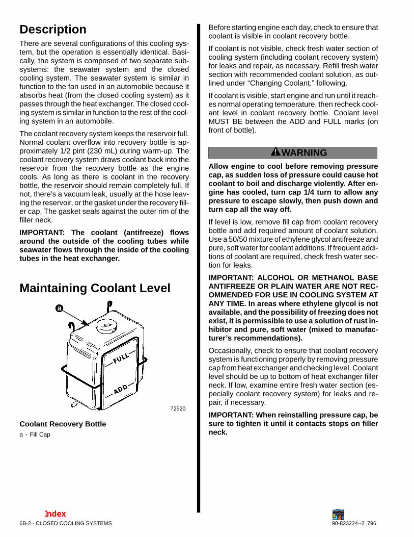
Maintaining Coolant Level
72520
a
Coolant Recovery Bottlea - Fill Cap
Before starting engine each day, check to ensure thatcoolant is visible in coolant recovery bottle.
If coolant is not visible, check fresh water section ofcooling system (including coolant recovery system)for leaks and repair, as necessary. Refill fresh watersection with recommended coolant solution, as out-lined under “Changing Coolant,” following.
If coolant is visible, start engine and run until it reach-es normal operating temperature, then recheck cool-ant level in coolant recovery bottle. Coolant levelMUST BE between the ADD and FULL marks (onfront of bottle).
! WARNINGAllow engine to cool before removing pressurecap, as sudden loss of pressure could cause hotcoolant to boil and discharge violently. After en-gine has cooled, turn cap 1/4 turn to allow anypressure to escape slowly, then push down andturn cap all the way off.
If level is low, remove fill cap from coolant recoverybottle and add required amount of coolant solution.Use a 50/50 mixture of ethylene glycol antifreeze andpure, soft water for coolant additions. If frequent addi-tions of coolant are required, check fresh water sec-tion for leaks.
IMPORTANT: ALCOHOL OR METHANOL BASEANTIFREEZE OR PLAIN WATER ARE NOT REC-OMMENDED FOR USE IN COOLING SYSTEM ATANY TIME. In areas where ethylene glycol is notavailable, and the possibility of freezing does notexist, it is permissible to use a solution of rust in-hibitor and pure, soft water (mixed to manufac-turer’s recommendations).
Occasionally, check to ensure that coolant recoverysystem is functioning properly by removing pressurecap from heat exchanger and checking level. Coolantlevel should be up to bottom of heat exchanger fillerneck. If low, examine entire fresh water section (es-pecially coolant recovery system) for leaks and re-pair, if necessary.
IMPORTANT: When reinstalling pressure cap, besure to tighten it until it contacts stops on fillerneck.
CLOSED COOLING SYSTEMS - 6B-390-823324--2 796
Pressure Cap MaintenancePressure cap is designed to maintain pressure infresh water section of closed cooling system once theengine has attained normal operating temperature.This raises the boiling point of the coolant, thereby in-creasing the efficiency of the cooling system. To helpensure proper operation, cap should be cleaned, in-spected and pressure tested periodically as follows:
! WARNINGAllow engine to cool before removing pressurecap (in next step), as sudden loss of pressurecould cause hot coolant to boil and discharge vi-olently. After engine has cooled, turn cap 1/4 turnto allow any pressure to escape slowly, thenpush down and turn cap all the way off.
1. Remove pressure cap from heat exchanger.
2. Wash cap with clean water to remove any depos-its or debris from sealing surfaces.
3. Inspect rubber seal on cap for cuts, cracks or oth-er signs of deterioration. If seal is damaged, capMUST BE replaced.
4. Inspect coolant recovery gasket for deteriorationand replace if bad.
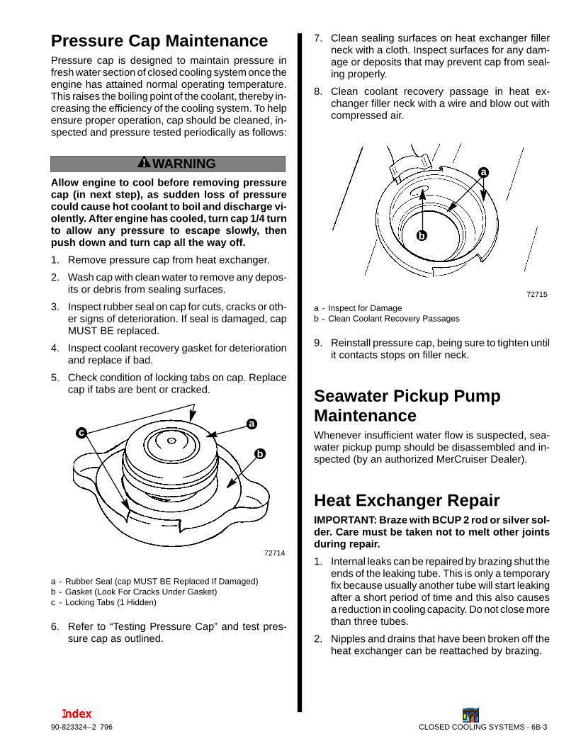
5. Check condition of locking tabs on cap. Replacecap if tabs are bent or cracked.
72714
b
ca
a - Rubber Seal (cap MUST BE Replaced If Damaged)b - Gasket (Look For Cracks Under Gasket)c - Locking Tabs (1 Hidden)
6. Refer to “Testing Pressure Cap” and test pres-sure cap as outlined.
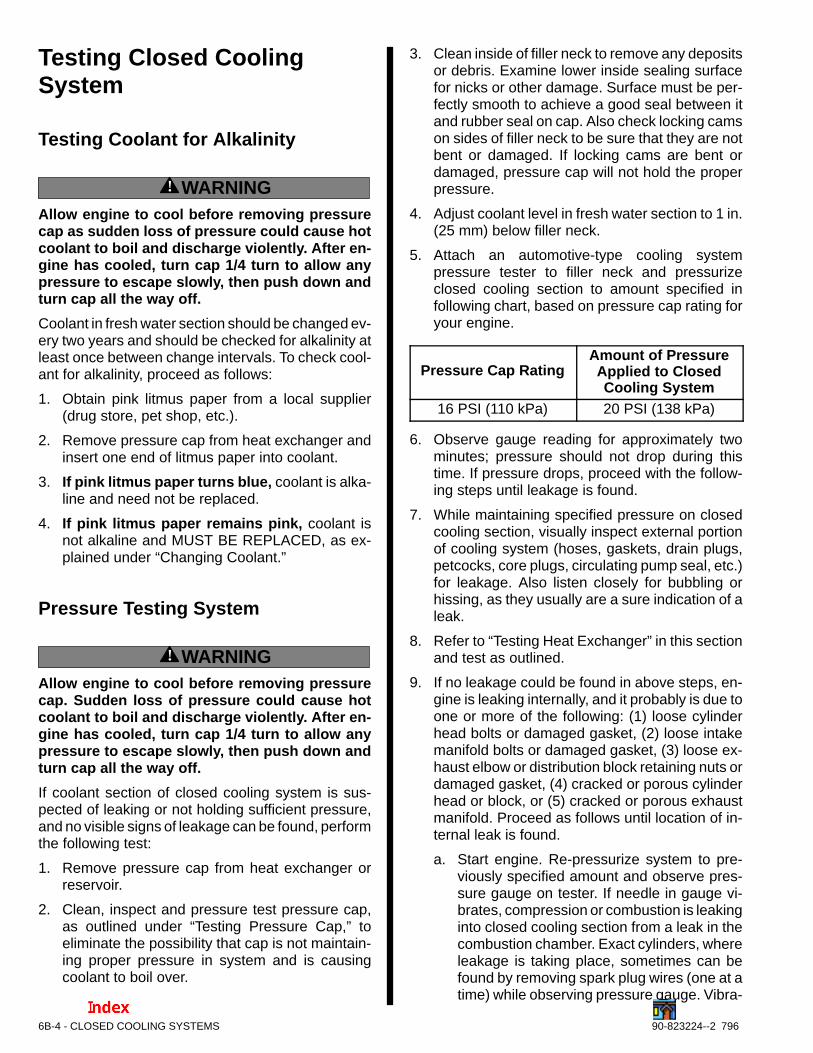
7. Clean sealing surfaces on heat exchanger fillerneck with a cloth. Inspect surfaces for any dam-age or deposits that may prevent cap from seal-ing properly.
8. Clean coolant recovery passage in heat ex-changer filler neck with a wire and blow out withcompressed air.
72715
b
a
a - Inspect for Damageb - Clean Coolant Recovery Passages
9. Reinstall pressure cap, being sure to tighten untilit contacts stops on filler neck.
Seawater Pickup PumpMaintenanceWhenever insufficient water flow is suspected, sea-water pickup pump should be disassembled and in-spected (by an authorized MerCruiser Dealer).
Heat Exchanger RepairIMPORTANT: Braze with BCUP 2 rod or silver sol-der. Care must be taken not to melt other jointsduring repair.
1. Internal leaks can be repaired by brazing shut theends of the leaking tube. This is only a temporaryfix because usually another tube will start leakingafter a short period of time and this also causesa reduction in cooling capacity. Do not close morethan three tubes.
2. Nipples and drains that have been broken off theheat exchanger can be reattached by brazing.
6B-4 - CLOSED COOLING SYSTEMS 90-823224--2 796
Testing Closed CoolingSystem
Testing Coolant for Alkalinity
! WARNINGAllow engine to cool before removing pressurecap as sudden loss of pressure could cause hotcoolant to boil and discharge violently. After en-gine has cooled, turn cap 1/4 turn to allow anypressure to escape slowly, then push down andturn cap all the way off.
Coolant in fresh water section should be changed ev-ery two years and should be checked for alkalinity atleast once between change intervals. To check cool-ant for alkalinity, proceed as follows:
1. Obtain pink litmus paper from a local supplier(drug store, pet shop, etc.).
2. Remove pressure cap from heat exchanger andinsert one end of litmus paper into coolant.
3. If pink litmus paper turns blue, coolant is alka-line and need not be replaced.
4. If pink litmus paper remains pink, coolant isnot alkaline and MUST BE REPLACED, as ex-plained under “Changing Coolant.”
Pressure Testing System
! WARNINGAllow engine to cool before removing pressurecap. Sudden loss of pressure could cause hotcoolant to boil and discharge violently. After en-gine has cooled, turn cap 1/4 turn to allow anypressure to escape slowly, then push down andturn cap all the way off.
If coolant section of closed cooling system is sus-pected of leaking or not holding sufficient pressure,and no visible signs of leakage can be found, performthe following test:
1. Remove pressure cap from heat exchanger orreservoir.
2. Clean, inspect and pressure test pressure cap,as outlined under “Testing Pressure Cap,” toeliminate the possibility that cap is not maintain-ing proper pressure in system and is causingcoolant to boil over.
3. Clean inside of filler neck to remove any depositsor debris. Examine lower inside sealing surfacefor nicks or other damage. Surface must be per-fectly smooth to achieve a good seal between itand rubber seal on cap. Also check locking camson sides of filler neck to be sure that they are notbent or damaged. If locking cams are bent ordamaged, pressure cap will not hold the properpressure.
4. Adjust coolant level in fresh water section to 1 in.(25 mm) below filler neck.
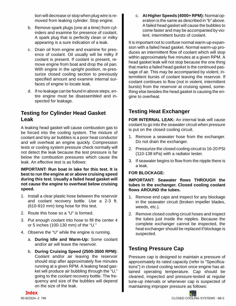
5. Attach an automotive-type cooling systempressure tester to filler neck and pressurizeclosed cooling section to amount specified infollowing chart, based on pressure cap rating foryour engine.
Pressure Cap RatingAmount of PressureApplied to ClosedCooling System
16 PSI (110 kPa) 20 PSI (138 kPa)
6. Observe gauge reading for approximately twominutes; pressure should not drop during thistime. If pressure drops, proceed with the follow-ing steps until leakage is found.
7. While maintaining specified pressure on closedcooling section, visually inspect external portionof cooling system (hoses, gaskets, drain plugs,petcocks, core plugs, circulating pump seal, etc.)for leakage. Also listen closely for bubbling orhissing, as they usually are a sure indication of aleak.
8. Refer to “Testing Heat Exchanger” in this sectionand test as outlined.
9. If no leakage could be found in above steps, en-gine is leaking internally, and it probably is due toone or more of the following: (1) loose cylinderhead bolts or damaged gasket, (2) loose intakemanifold bolts or damaged gasket, (3) loose ex-haust elbow or distribution block retaining nuts ordamaged gasket, (4) cracked or porous cylinderhead or block, or (5) cracked or porous exhaustmanifold. Proceed as follows until location of in-ternal leak is found.
a. Start engine. Re-pressurize system to pre-viously specified amount and observe pres-sure gauge on tester. If needle in gauge vi-brates, compression or combustion is leakinginto closed cooling section from a leak in thecombustion chamber. Exact cylinders, whereleakage is taking place, sometimes can befound by removing spark plug wires (one at atime) while observing pressure gauge. Vibra-
CLOSED COOLING SYSTEMS - 6B-590-823324--2 796
tion will decrease or stop when plug wire is re-moved from leaking cylinder. Stop engine.
b. Remove spark plugs (one at a time) from cyl-inders and examine for presence of coolant.A spark plug that is perfectly clean or milkyappearing is a sure indication of a leak.
c. Drain oil from engine and examine for pres-ence of coolant. Oil usually will be milky ifcoolant is present. If coolant is present, re-move engine from boat and drop the oil pan.With engine in the upright position, re-pres-surize closed cooling section to previouslyspecified amount and examine internal sur-faces of engine to locate leak.
d. If no leakage can be found in above steps, en-tire engine must be disassembled and in-spected for leakage.
Testing for Cylinder Head GasketLeakA leaking head gasket will cause combustion gas tobe forced into the cooling system. The mixture ofcoolant and tiny air bubbles is a poor heat conductorand will overheat an engine quickly. Compressiontests or cooling system pressure check normally willnot detect the leak because the test pressure is farbelow the combustion pressures which cause theleak. An effective test is as follows:
IMPORTANT: Run boat in lake for this test. It isbest to run the engine at or above cruising speedduring this test. Usually a failed head gasket willnot cause the engine to overheat below cruisingspeed.
1. Install a clear plastic hose between the reservoirand coolant recovery bottle. Use a 2-3 ft.(610-910 mm) long hose for this test.
2. Route this hose so a “U” is formed.
3. Put enough coolant into hose to fill the center 4or 5 inches (100-130 mm) of the “U.”
4. Observe the “U” while the engine is running.
a. During Idle and Warm-Up: Some coolantand/or air will leave the reservoir.
b. During Cruising Speed (2500-3500 RPM):Coolant and/or air leaving the reservoirshould stop after approximately five minutesrunning at a given RPM. A leaking head gas-ket will produce air bubbling through the “U,”going to the coolant recovery bottle. The fre-quency and size of the bubbles will dependon the size of the leak.
c. At Higher Speeds (4000+ RPM): Normal op-eration is the same as described in “b” above.A failed head gasket will cause the bubbles tocome faster and may be accompanied by vio-lent, intermittent bursts of coolant.
It is important not to confuse normal warm-up expan-sion with a failed head gasket. Normal warm-up pro-duces an intermittent flow of coolant which will stopwithin approximately five minutes at a given RPM. Ahead gasket leak will not stop because the one thingthat marks a failed head gasket is the continued pas-sage of air. This may be accompanied by violent, in-termittent bursts of coolant leaving the reservoir. Ifcoolant continues to flow (not in violent, intermittentbursts) from the reservoir at cruising speed, some-thing else besides the head gasket is causing the en-gine to overheat.
Testing Heat ExchangerFOR INTERNAL LEAK: An internal leak will causecoolant to go into the seawater circuit when pressureis put on the closed cooling circuit.
1. Remove a seawater hose from the exchanger.Do not drain the exchanger.
2. Pressurize the closed cooling circuit to 16-20 PSI(110-138 kPa) with a radiator tester.
3. If seawater begins to flow from the nipple there isa leak.
FOR BLOCKAGE:
IMPORTANT: Seawater flows THROUGH thetubes in the exchanger. Closed cooling coolantflows AROUND the tubes.
1. Remove end caps and inspect for any blockagein the seawater circuit (broken impeller blades,weeds, etc.).
2. Remove closed cooling circuit hoses and inspectthe tubes just inside the nipples. Because thecomplete exchanger cannot be inspected, theheat exchanger should be replaced if blockage issuspected.
Testing Pressure CapPressure cap is designed to maintain a pressure ofapproximately its rated capacity (refer to “Specifica-tions”) in closed cooling section once engine has at-tained operating temperature. Cap should becleaned, inspected and pressure-tested at regulartune-up intervals or whenever cap is suspected ofmaintaining improper pressure as follows:
6B-6 - CLOSED COOLING SYSTEMS 90-823224--2 796
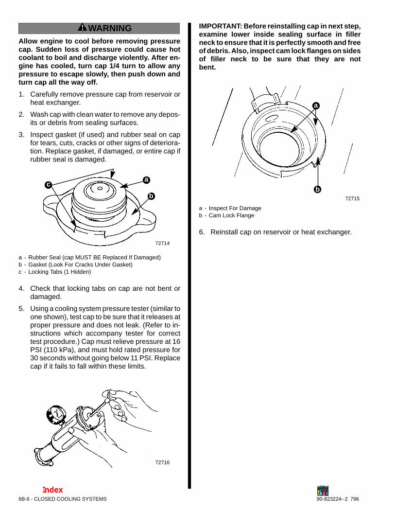
! WARNINGAllow engine to cool before removing pressurecap. Sudden loss of pressure could cause hotcoolant to boil and discharge violently. After en-gine has cooled, turn cap 1/4 turn to allow anypressure to escape slowly, then push down andturn cap all the way off.
1. Carefully remove pressure cap from reservoir orheat exchanger.
2. Wash cap with clean water to remove any depos-its or debris from sealing surfaces.
3. Inspect gasket (if used) and rubber seal on capfor tears, cuts, cracks or other signs of deteriora-tion. Replace gasket, if damaged, or entire cap ifrubber seal is damaged.
72714
b
ca
a - Rubber Seal (cap MUST BE Replaced If Damaged)b - Gasket (Look For Cracks Under Gasket)c - Locking Tabs (1 Hidden)
4. Check that locking tabs on cap are not bent ordamaged.
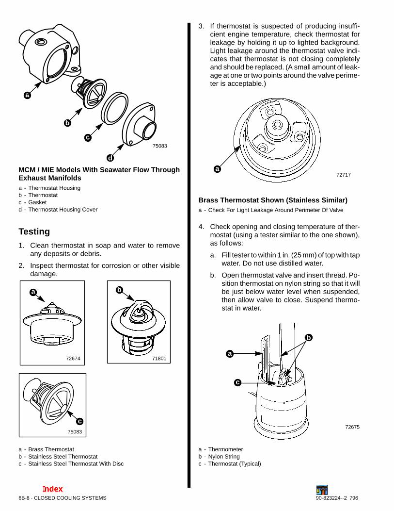
5. Using a cooling system pressure tester (similar toone shown), test cap to be sure that it releases atproper pressure and does not leak. (Refer to in-structions which accompany tester for correcttest procedure.) Cap must relieve pressure at 16PSI (110 kPa), and must hold rated pressure for30 seconds without going below 11 PSI. Replacecap if it fails to fall within these limits.
72716
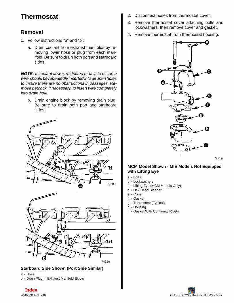
IMPORTANT: Before reinstalling cap in next step,examine lower inside sealing surface in fillerneck to ensure that it is perfectly smooth and freeof debris. Also, inspect cam lock flanges on sidesof filler neck to be sure that they are notbent.
72715
b
a
a - Inspect For Damageb - Cam Lock Flange
6. Reinstall cap on reservoir or heat exchanger.
CLOSED COOLING SYSTEMS - 6B-790-823324--2 796
Thermostat
Removal1. Follow instructions “a” and “b”:
a. Drain coolant from exhaust manifolds by re-moving lower hose or plug from each man-ifold. Be sure to drain both port and starboardsides.
NOTE: If coolant flow is restricted or fails to occur, awire should be repeatedly inserted into all drain holesto insure there are no obstructions in passages. Re-move petcock, if necessary, to insert wire completelyinto drain hole.
b. Drain engine block by removing drain plug.Be sure to drain both port and starboardsides.
72609a
b74130
Starboard Side Shown (Port Side Similar)a - Hoseb - Drain Plug In Exhaust Manifold Elbow
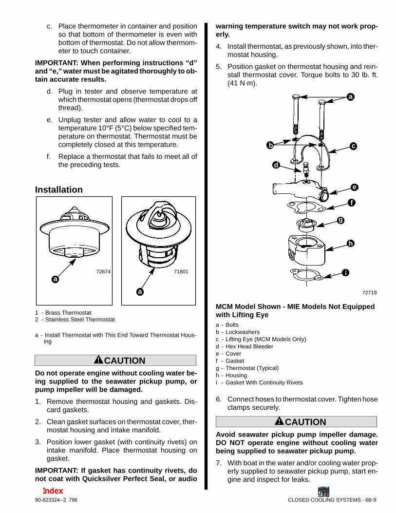
2. Disconnect hoses from thermostat cover.
3. Remove thermostat cover attaching bolts andlockwashers, then remove cover and gasket.
4. Remove thermostat from thermostat housing.
72719
b c
d
e
f
g
h
i
a
MCM Model Shown - MIE Models Not Equipped with Lifting Eyea - Boltsb - Lockwashersc - Lifting Eye (MCM Models Only)d - Hex Head Bleedere - Coverf - Gasketg - Thermostat (Typical)h - Housingi - Gasket With Continuity Rivets
6B-8 - CLOSED COOLING SYSTEMS 90-823224--2 796
75083
c
a
b
d
MCM / MIE Models With Seawater Flow ThroughExhaust Manifoldsa - Thermostat Housingb - Thermostatc - Gasketd - Thermostat Housing Cover
Testing1. Clean thermostat in soap and water to remove
any deposits or debris.
2. Inspect thermostat for corrosion or other visibledamage.
7180172674
ba
75083
c
a - Brass Thermostatb - Stainless Steel Thermostatc - Stainless Steel Thermostat With Disc
3. If thermostat is suspected of producing insuffi-cient engine temperature, check thermostat forleakage by holding it up to lighted background.Light leakage around the thermostat valve indi-cates that thermostat is not closing completelyand should be replaced. (A small amount of leak-age at one or two points around the valve perime-ter is acceptable.)
72717a
Brass Thermostat Shown (Stainless Similar)a - Check For Light Leakage Around Perimeter Of Valve
4. Check opening and closing temperature of ther-mostat (using a tester similar to the one shown),as follows:
a. Fill tester to within 1 in. (25 mm) of top with tapwater. Do not use distilled water.
b. Open thermostat valve and insert thread. Po-sition thermostat on nylon string so that it willbe just below water level when suspended,then allow valve to close. Suspend thermo-stat in water.
72675
b
c
a
a - Thermometerb - Nylon Stringc - Thermostat (Typical)
CLOSED COOLING SYSTEMS - 6B-990-823324--2 796
c. Place thermometer in container and positionso that bottom of thermometer is even withbottom of thermostat. Do not allow thermom-eter to touch container.
IMPORTANT: When performing instructions “d”and “e,” water must be agitated thoroughly to ob-tain accurate results.
d. Plug in tester and observe temperature atwhich thermostat opens (thermostat drops offthread).
e. Unplug tester and allow water to cool to atemperature 10°F (5°C) below specified tem-perature on thermostat. Thermostat must becompletely closed at this temperature.
f. Replace a thermostat that fails to meet all ofthe preceding tests.
Installation
72674
a
a
71801
1 - Brass Thermostat2 - Stainless Steel Thermostat
a - Install Thermostat with This End Toward Thermostat Hous-ing
! CAUTIONDo not operate engine without cooling water be-ing supplied to the seawater pickup pump, orpump impeller will be damaged.
1. Remove thermostat housing and gaskets. Dis-card gaskets.
2. Clean gasket surfaces on thermostat cover, ther-mostat housing and intake manifold.
3. Position lower gasket (with continuity rivets) onintake manifold. Place thermostat housing ongasket.
IMPORTANT: If gasket has continuity rivets, donot coat with Quicksilver Perfect Seal, or audio
warning temperature switch may not work prop-erly.
4. Install thermostat, as previously shown, into ther-mostat housing.
5. Position gasket on thermostat housing and rein-stall thermostat cover. Torque bolts to 30 lb. ft.(41 N·m).
72719
b c
d
e
f
g
h
i
a
MCM Model Shown - MIE Models Not Equipped with Lifting Eyea - Boltsb - Lockwashersc - Lifting Eye (MCM Models Only)d - Hex Head Bleedere - Coverf - Gasketg - Thermostat (Typical)h - Housingi - Gasket With Continuity Rivets
6. Connect hoses to thermostat cover. Tighten hoseclamps securely.
! CAUTIONAvoid seawater pickup pump impeller damage.DO NOT operate engine without cooling waterbeing supplied to seawater pickup pump.
7. With boat in the water and/or cooling water prop-erly supplied to seawater pickup pump, start en-gine and inspect for leaks.
6B-10 - CLOSED COOLING SYSTEMS 90-823224--2 796
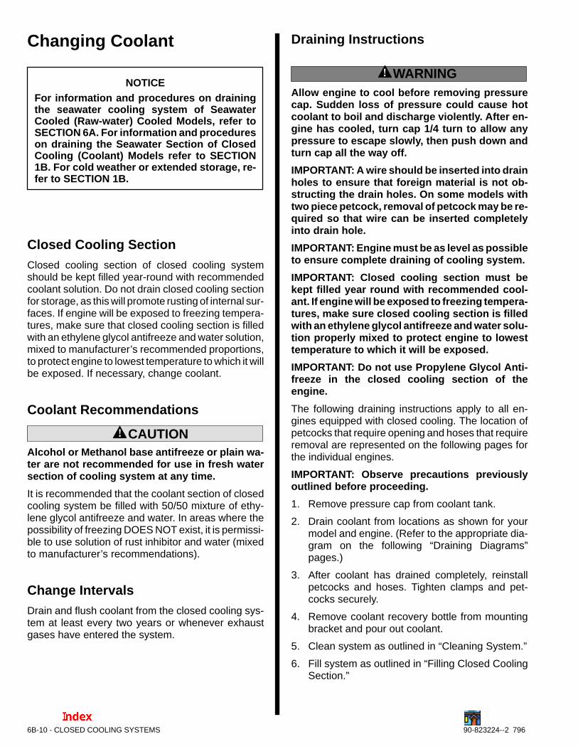
Changing Coolant
NOTICEFor information and procedures on drainingthe seawater cooling system of SeawaterCooled (Raw-water) Cooled Models, refer toSECTION 6A. For information and procedureson draining the Seawater Section of ClosedCooling (Coolant) Models refer to SECTION1B. For cold weather or extended storage, re-fer to SECTION 1B.
Closed Cooling SectionClosed cooling section of closed cooling systemshould be kept filled year-round with recommendedcoolant solution. Do not drain closed cooling sectionfor storage, as this will promote rusting of internal sur-faces. If engine will be exposed to freezing tempera-tures, make sure that closed cooling section is filledwith an ethylene glycol antifreeze and water solution,mixed to manufacturer’s recommended proportions,to protect engine to lowest temperature to which it willbe exposed. If necessary, change coolant.
Coolant Recommendations
! CAUTIONAlcohol or Methanol base antifreeze or plain wa-ter are not recommended for use in fresh watersection of cooling system at any time.
It is recommended that the coolant section of closedcooling system be filled with 50/50 mixture of ethy-lene glycol antifreeze and water. In areas where thepossibility of freezing DOES NOT exist, it is permissi-ble to use solution of rust inhibitor and water (mixedto manufacturer’s recommendations).
Change IntervalsDrain and flush coolant from the closed cooling sys-tem at least every two years or whenever exhaustgases have entered the system.
Draining Instructions
! WARNINGAllow engine to cool before removing pressurecap. Sudden loss of pressure could cause hotcoolant to boil and discharge violently. After en-gine has cooled, turn cap 1/4 turn to allow anypressure to escape slowly, then push down andturn cap all the way off.
IMPORTANT: A wire should be inserted into drainholes to ensure that foreign material is not ob-structing the drain holes. On some models withtwo piece petcock, removal of petcock may be re-quired so that wire can be inserted completelyinto drain hole.
IMPORTANT: Engine must be as level as possibleto ensure complete draining of cooling system.
IMPORTANT: Closed cooling section must bekept filled year round with recommended cool-ant. If engine will be exposed to freezing tempera-tures, make sure closed cooling section is filledwith an ethylene glycol antifreeze and water solu-tion properly mixed to protect engine to lowesttemperature to which it will be exposed.
IMPORTANT: Do not use Propylene Glycol Anti-freeze in the closed cooling section of theengine.
The following draining instructions apply to all en-gines equipped with closed cooling. The location ofpetcocks that require opening and hoses that requireremoval are represented on the following pages forthe individual engines.
IMPORTANT: Observe precautions previouslyoutlined before proceeding.
1. Remove pressure cap from coolant tank.
2. Drain coolant from locations as shown for yourmodel and engine. (Refer to the appropriate dia-gram on the following “Draining Diagrams”pages.)
3. After coolant has drained completely, reinstallpetcocks and hoses. Tighten clamps and pet-cocks securely.
4. Remove coolant recovery bottle from mountingbracket and pour out coolant.
5. Clean system as outlined in “Cleaning System.”
6. Fill system as outlined in “Filling Closed CoolingSection.”
CLOSED COOLING SYSTEMS - 6B-1190-823324--2 796
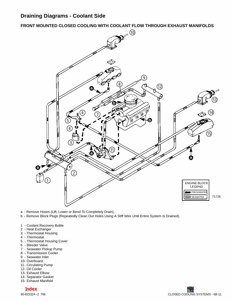
Draining Diagrams - Coolant Side
FRONT MOUNTED CLOSED COOLING WITH COOLANT FLOW THROUGH EXHAUST MANIFOLDS
ENGINE BLOCKLEGEND
FRESHWATER
SEAWATER 71726
b
b
a
1
2
3
4
5
6 7
8
9
10
11
12
13
14
15
a
a
a
a - Remove Hoses (Lift, Lower or Bend To Completely Drain).b - Remove Block Plugs (Repeatedly Clean Out Holes Using A Stiff Wire Until Entire System Is Drained).
1 - Coolant Recovery Bottle2 - Heat Exchanger3 - Thermostat Housing4 - Thermostat5 - Thermostat Housing Cover6 - Bleeder Valve7 - Seawater Pickup Pump8 - Transmission Cooler9 - Seawater Inlet10- Overboard11- Circulating Pump12- Oil Cooler13- Exhaust Elbow14- Separator Gasket15- Exhaust Manifold
6B-12 - CLOSED COOLING SYSTEMS 90-823224--2 796
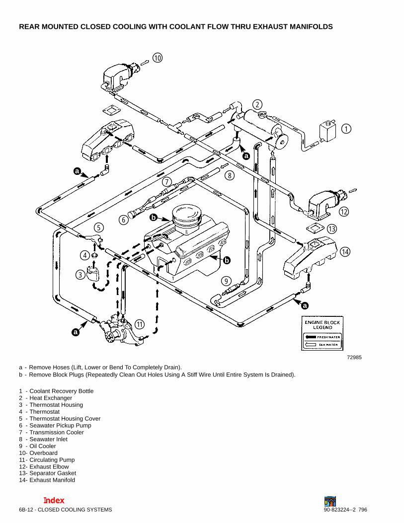
REAR MOUNTED CLOSED COOLING WITH COOLANT FLOW THRU EXHAUST MANIFOLDS
72985
a
a
b
b
1
2
3
4
56
78
9
10
11
12
13
14
a
a
a - Remove Hoses (Lift, Lower or Bend To Completely Drain).b - Remove Block Plugs (Repeatedly Clean Out Holes Using A Stiff Wire Until Entire System Is Drained).
1 - Coolant Recovery Bottle2 - Heat Exchanger3 - Thermostat Housing4 - Thermostat5 - Thermostat Housing Cover6 - Seawater Pickup Pump7 - Transmission Cooler8 - Seawater Inlet9 - Oil Cooler10- Overboard11- Circulating Pump12- Exhaust Elbow13- Separator Gasket14- Exhaust Manifold
CLOSED COOLING SYSTEMS - 6B-1390-823324--2 796
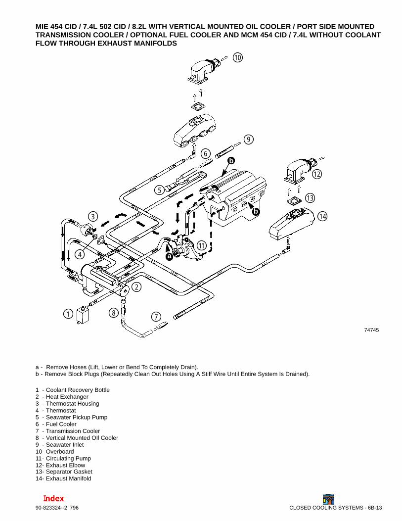
MIE 454 CID / 7.4L 502 CID / 8.2L WITH VERTICAL MOUNTED OIL COOLER / PORT SIDE MOUNTEDTRANSMISSION COOLER / OPTIONAL FUEL COOLER AND MCM 454 CID / 7.4L WITHOUT COOLANTFLOW THROUGH EXHAUST MANIFOLDS
74745
b
a
1
2
3
5
6
78
9
10
11
12
13
14
b
4
a - Remove Hoses (Lift, Lower or Bend To Completely Drain).b - Remove Block Plugs (Repeatedly Clean Out Holes Using A Stiff Wire Until Entire System Is Drained).
1 - Coolant Recovery Bottle2 - Heat Exchanger3 - Thermostat Housing4 - Thermostat5 - Seawater Pickup Pump6 - Fuel Cooler7 - Transmission Cooler8 - Vertical Mounted OIl Cooler9 - Seawater Inlet10- Overboard11- Circulating Pump12- Exhaust Elbow13- Separator Gasket14- Exhaust Manifold
6B-14 - CLOSED COOLING SYSTEMS 90-823224--2 796
Cleaning System
Closed Cooling SectionClosed cooling section of closed cooling systemshould be cleaned at least once every two years orwhenever decreased cooling efficiency is experi-enced.
A good grade automotive cooling system cleaningsolution may be used to remove rust, scale or otherforeign material. Always follow manufacturer’s in-structions for the cleaner.
If closed cooling section is extremely dirty, a pressureflushing device may be used to flush out remainingdeposits. Flushing should be done in direction oppo-site normal coolant flow to allow water to get behinddeposits and force them out. Refer to instructionswhich accompany flushing device for proper hookupand flushing procedure.
NOTICEFor information and procedures for drainingand flushing Seawater Section of ClosedCooling (Coolant) Models, refer to SECTION1B. For cold weather or extended storage, re-fer to SECTION 1B.
Seawater SectionCooling efficiency of an engine with closed cooling isgreatly dependent upon heat transfer through thetubes within the heat exchanger. During engine oper-ation, contaminants within the seawater (such assalt, silt, lime, etc.) collect on the inside of the tubes,thus reducing heat transfer and greatly decreasingheat exchanger efficiency. It is, therefore, recom-mended that the seawater section of the heat ex-changer be cleaned at least once every two years orwhenever decreased cooling efficiency is suspected,as follows:
IMPORTANT: It may be necessary to remove heatexchanger on some models. If heat exchanger isremoved, be sure to refill closed cooling sectionwith coolant.
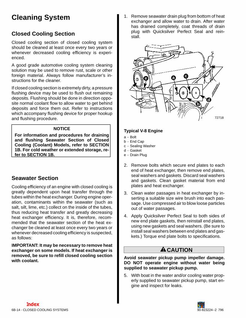
1. Remove seawater drain plug from bottom of heatexchanger and allow water to drain. After waterhas drained completely, coat threads of drainplug with Quicksilver Perfect Seal and rein-stall.
72718
b
c
d
ae
Typical V-8 Enginea - Boltb - End Capc - Sealing Washerd - Gaskete - Drain Plug
2. Remove bolts which secure end plates to eachend of heat exchanger, then remove end plates,seal washers and gaskets. Discard seal washersand gaskets. Clean gasket material from endplates and heat exchanger.
3. Clean water passages in heat exchanger by in-serting a suitable size wire brush into each pas-sage. Use compressed air to blow loose particlesout of water passages.
4. Apply Quicksilver Perfect Seal to both sides ofnew end plate gaskets, then reinstall end plates,using new gaskets and seal washers. (Be sure toinstall seal washers between end plates and gas-kets.) Torque end plate bolts to specifications.
! CAUTIONAvoid seawater pickup pump impeller damage.DO NOT operate engine without water beingsupplied to seawater pickup pump.
5. With boat in the water and/or cooling water prop-erly supplied to seawater pickup pump, start en-gine and inspect for leaks.
CLOSED COOLING SYSTEMS - 6B-1590-823324--2 796
Filling Closed CoolingSection
Fresh Water Flow Thru ExhaustManifold
NOTICE
See “Specifications” for approximateclosed cooling system capacity and cool-ant recommendation.
! WARNINGDo not remove coolant cap when engine is hot.Coolant may discharge violently.
! CAUTIONAlcohol or Methanol based antifreeze or plainwater are not recommended for use in fresh wa-ter section of cooling system at any time.
! CAUTIONFront of engine should be higher than rear topurge trapped air out of the system during initialfilling. This will minimize the possibility of air be-ing trapped in the closed cooling section whichcan cause engine to overheat.
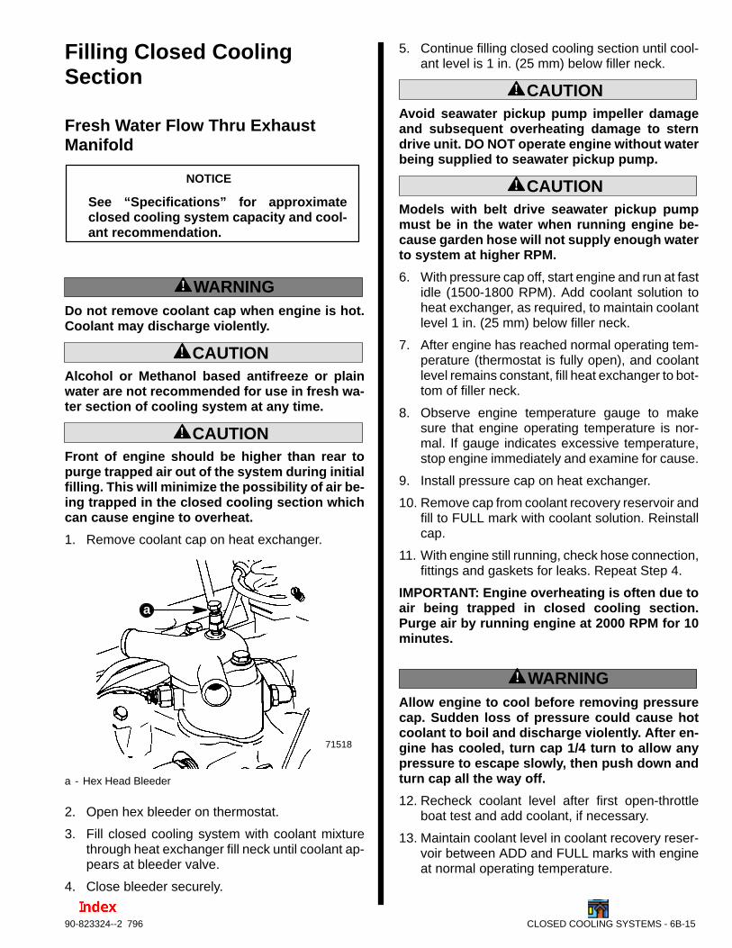
1. Remove coolant cap on heat exchanger.
71518
a
a - Hex Head Bleeder
2. Open hex bleeder on thermostat.
3. Fill closed cooling system with coolant mixturethrough heat exchanger fill neck until coolant ap-pears at bleeder valve.
4. Close bleeder securely.
5. Continue filling closed cooling section until cool-ant level is 1 in. (25 mm) below filler neck.
! CAUTIONAvoid seawater pickup pump impeller damageand subsequent overheating damage to sterndrive unit. DO NOT operate engine without waterbeing supplied to seawater pickup pump.
! CAUTIONModels with belt drive seawater pickup pumpmust be in the water when running engine be-cause garden hose will not supply enough waterto system at higher RPM.
6. With pressure cap off, start engine and run at fastidle (1500-1800 RPM). Add coolant solution toheat exchanger, as required, to maintain coolantlevel 1 in. (25 mm) below filler neck.
7. After engine has reached normal operating tem-perature (thermostat is fully open), and coolantlevel remains constant, fill heat exchanger to bot-tom of filler neck.
8. Observe engine temperature gauge to makesure that engine operating temperature is nor-mal. If gauge indicates excessive temperature,stop engine immediately and examine for cause.
9. Install pressure cap on heat exchanger.
10. Remove cap from coolant recovery reservoir andfill to FULL mark with coolant solution. Reinstallcap.
11. With engine still running, check hose connection,fittings and gaskets for leaks. Repeat Step 4.
IMPORTANT: Engine overheating is often due toair being trapped in closed cooling section.Purge air by running engine at 2000 RPM for 10minutes.
! WARNINGAllow engine to cool before removing pressurecap. Sudden loss of pressure could cause hotcoolant to boil and discharge violently. After en-gine has cooled, turn cap 1/4 turn to allow anypressure to escape slowly, then push down andturn cap all the way off.
12. Recheck coolant level after first open-throttleboat test and add coolant, if necessary.
13. Maintain coolant level in coolant recovery reser-voir between ADD and FULL marks with engineat normal operating temperature.
6B-16 - CLOSED COOLING SYSTEMS 90-823224--2 796
Seawater Flow Thru ExhaustManifolds
! CAUTIONAlcohol or Methanol base antifreeze or plain wa-ter, are not recommended for use in coolant sec-tion of Closed Cooling System at any time.
It is recommended that coolant section of ClosedCooling System be filled with a 50/50 mixture of ethy-lene glycol antifreeze and pure, soft water. AntifreezeMUST BE used regardless of whether freezing tem-peratures are or are not expected to provide ade-quate corrosion protection. In areas where ethyleneglycol antifreeze is not available and the possibility offreezing DOES NOT exist, it is permissible to use asolution of rust inhibitor and pure, soft water (mixedto manufacturer’s recommendations).
NOTE: Coolant section capacity is approximately 4U.S. Gallons (15 L).
1. Fill coolant section of Closed Cooling Systemwith coolant mixture as follows:
a. Open bleeder valve on thermostat housing.
b. Fill with coolant mixture through heat ex-changer fill neck until coolant appears atbleeder valve opening.
c. Close bleeder valve securely.
d. Continue filling until coolant level is into fillerneck and begins to flow into coolant recoverybottle plastic tubing.
! CAUTIONDO NOT operate engine without water flowingthru seawater pickup pump, as pump impellermay be damaged and subsequent overheatingdamage to engine or stern drive unit may result.
• Front of engine should be higher than rear topurge trapped air out of the system during initialfilling. This will minimize the possibility of air be-ing trapped in the closed cooling section whichcan cause engine to overheat.
IMPORTANT: This closed cooling system flowscoolant at a high rate. Higher idle speeds in-crease dispersion of trapped air into systemmaking it more difficult to purge trapped air. Op-erate at idle during filling and air purging whenspecified.
2. Start engine and run AT IDLE. Add coolantsolution to heat exchanger, as required, tomaintain coolant level at filler neck. After enginehas reached normal operating temperature (ther-mostat is fully open), and coolant level remainsconstant, fill heat exchanger until coolant level isinto filler neck and begins to flow into coolantrecovery bottle plastic tubing.
3. Remove cap from coolant recovery reservoir andfill to “Full” mark with coolant solution. Reinstallcap.
4. Lift recovery bottle and plastic tubing above heatexchanger filler neck. Allow coolant to flow downthrough tubing to purge air through filler neckfitting.
5. Install pressure cap on heat exchanger.
6. With engine still running, check hose connec-tions, fittings and gaskets for leaks. Also observeengine temperature gauge to make sure thatengine operating temperature is normal. If gaugeindicates excessive temperature, stop engineimmediately and examine for cause.
! WARNINGAllow engine to cool down before removing pres-sure cap. Sudden loss of pressure could causehot coolant to boil and discharge violently. Afterengine has cooled down, turn cap 1/4-turn to al-low any pressure to escape slowly, then, pushdown and turn cap all-the-way off.
7. Recheck coolant level after first open-throttleboat test and add coolant, if necessary.
8. Maintain coolant level in coolant recovery reser-voir between “Add” and “Full” marks with engineat normal operating temperature.
Coolant section of Closed Cooling System should bekept filled year around with recommended coolantsolution. DO NOT drain coolant, fresh water section,for storage, as this will promote rusting of internal sur-faces. If engine will be exposed to freezing tempera-tures, make sure that coolant section is filled withethylene glycol antifreeze and water solution, mixedto manufacturer’s recommended proportion, to pro-tect engine to lowest temperature to which it will beexposed.
CLOSED COOLING SYSTEMS - 6B-1790-823324--2 796
Auxiliary Hot Water HeaterInstallationIMPORTANT: When connecting a cabin heater orhot water heater, certain requirements must bemet.
• Supply hose (from engine to heater) and re-turn hose (from heater to engine) MUST NOTEXCEED 5/8 in. (15.8 mm) I.D. (inside diame-ter).
• Engine with a Closed Cooling System: HeaterMUST BE LOWER than fill cap on the heat ex-changer. If the heater is higher than the fill capon the heat exchanger and some coolant islost in the system, an air pocket may form inthe closed cooling system. This, in turn, cancause the engine to overheat.
• Make heater connections ONLY at locationsdescribed in the following instructions.
• Check complete system for leaks after heateris connected into cooling system.
• Check for overheating condition (of engine)after heater is connected.
1. Refer to “Changing Coolant - Draining Instruc-tions”; drain closed cooling system.
2. Inspect for appropriate location of supply hose atfollowing:
! CAUTIONAvoid a performance loss and/or possible enginedamage. Engine coolant must flow continuouslyfrom the engine intake manifold to the engine wa-ter circulating pump. NEVER close-off or blockthe coolant flow to or from a heater.All heater installations must be plumbed in se-ries with the supply and return connections.
NOTE: Hot water heater supply hose can be con-nected at several different locations. On some mod-els, there may be other accessories and options thatare utilizing these hot water supply locations. One ofthe following should be available for use when install-ing a hot water heater system.
NOTE: On some models it may be necessary to re-move the audio warning heat switch from port side ofthermostat housing and reposition to water circulat-ing pump opening as outlined following.
IMPORTANT: Do not reposition engine tempera-ture switch; it must remain where installed byfactory.
Recommended Supply Locations
71518
72702
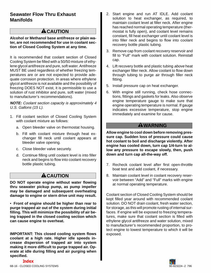
a
b
Thermostat Housing With Two Hose Connectiona - Audio Warning Switch Relocationb - Water Supply Location
75045
a
b
MIE 7.4L / MCM 7.4LX Throttle Body Injectiona - Location For Hot Water Supplyb - Factory Hose
6B-18 - CLOSED COOLING SYSTEMS 90-823224--2 796
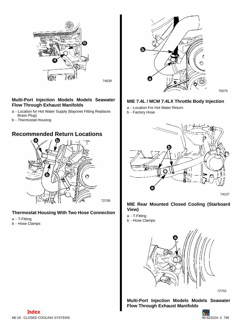
74639
a
b
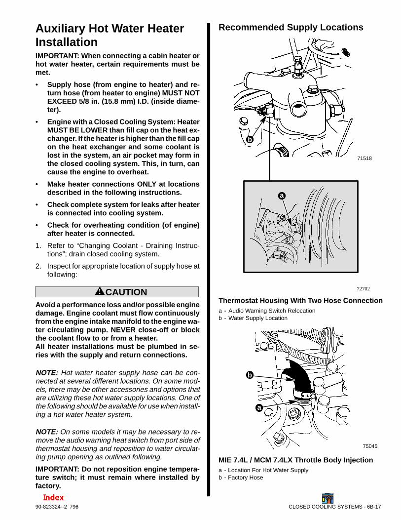
Multi-Port Injection Models Models SeawaterFlow Through Exhaust Manifoldsa - Location for Hot Water Supply (Bayonet Fitting Replaces
Brass Plug)b - Thermostat Housing
Recommended Return Locations
72705
b
a b
Thermostat Housing With Two Hose Connectiona - T-Fittingb - Hose Clamps
75075
b
a
MIE 7.4L / MCM 7.4LX Throttle Body Injectiona - Location For Hot Water Returnb - Factory Hose
74137
a
b
MIE Rear Mounted Closed Cooling (StarboardView)a - T-Fittingb - Hose Clamps
72702
a
Multi-Port Injection Models Models SeawaterFlow Through Exhaust Manifolds
CLOSED COOLING SYSTEMS - 6B-1990-823324--2 796
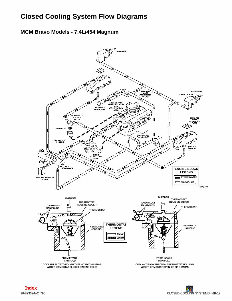
Closed Cooling System Flow Diagrams
MCM Bravo Models - 7.4L/454 Magnum
72962
TO EXHAUSTMANIFOLDS
TO EXHAUSTMANIFOLDS
THERMOSTATHOUSING COVER
THERMOSTATHOUSING COVER
THERMOSTATTHERMOSTAT
THERMOSTATHOUSING
THERMOSTATHOUSING
FROM INTAKEMANIFOLD
FROM INTAKEMANIFOLD
COOLANT FLOW THROUGH THERMOSTAT HOUSINGWITH THERMOSTAT CLOSED (ENGINE COLD)
COOLANT FLOW THROUGH THERMOSTAT HOUSINGWITH THERMOSTAT OPEN (ENGINE WARM)
THERMOSTATLEGEND
COLD
WARM
BLEEDERBLEEDER
ENGINE BLOCKLEGEND
FRESHWATER
SEAWATER
6B-20 - CLOSED COOLING SYSTEMS 90-823224--2 796
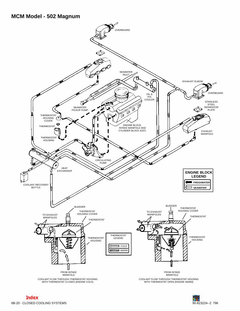
MCM Model - 502 Magnum
ENGINE BLOCKLEGEND
FRESHWATER
SEAWATER
OVERBOARD
OVERBOARD
EXHAUST ELBOW
STAINLESSSTEEL
SEPARATORPLATE
EXHAUSTMANIFOLD
ENGINE BLOCK,INTAKE MANIFOLD ANDCYLINDER BLOCK ASSY.
OIL &P/S
COOLER
SEAWATERPICKUP PUMP
SEAWATERINLET
THERMOSTATHOUSINGCOVER
THERMOSTAT
THERMOSTATHOUSING
HEATEXCHANGER
COOLANT RECOVERYBOTTLE
CIRCULATINGPUMP
TO EXHAUSTMANIFOLDS
TO EXHAUSTMANIFOLDS
THERMOSTATHOUSING COVER
THERMOSTATHOUSING COVER
THERMOSTATTHERMOSTAT
THERMOSTATHOUSING
THERMOSTATHOUSING
FROM INTAKEMANIFOLD
FROM INTAKEMANIFOLD
COOLANT FLOW THROUGH THERMOSTAT HOUSINGWITH THERMOSTAT CLOSED (ENGINE COLD)
COOLANT FLOW THROUGH THERMOSTAT HOUSINGWITH THERMOSTAT OPEN (ENGINE WARM)
THERMOSTATLEGEND
COLD
WARM
BLEEDERBLEEDER
CLOSED COOLING SYSTEMS - 6B-2190-823324--2 796
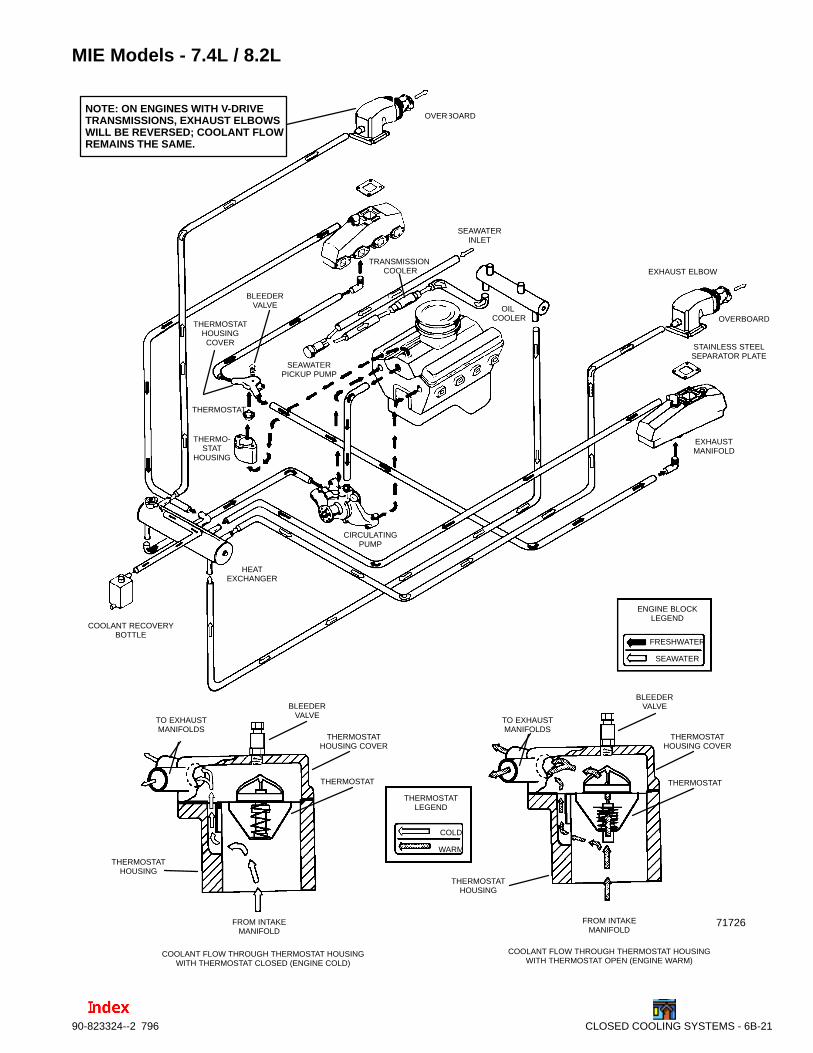
MIE Models - 7.4L / 8.2L
ENGINE BLOCKLEGEND
FRESHWATER
SEAWATER
THERMOSTATLEGEND
COLD
WARM
OVERBOARD
OVERBOARD
EXHAUST ELBOW
STAINLESS STEELSEPARATOR PLATE
EXHAUSTMANIFOLD
OIL COOLER
SEAWATERPICKUP PUMP
SEAWATERINLET
THERMOSTATHOUSINGCOVER
THERMOSTAT
THERMO-STAT
HOUSING
HEATEXCHANGER
COOLANT RECOVERYBOTTLE
CIRCULATINGPUMP
THERMOSTATHOUSING COVER
THERMOSTAT THERMOSTAT
THERMOSTATHOUSING
THERMOSTATHOUSING
TO EXHAUSTMANIFOLDS
TO EXHAUSTMANIFOLDS
FROM INTAKEMANIFOLD
FROM INTAKEMANIFOLD
COOLANT FLOW THROUGH THERMOSTAT HOUSINGWITH THERMOSTAT CLOSED (ENGINE COLD)
COOLANT FLOW THROUGH THERMOSTAT HOUSINGWITH THERMOSTAT OPEN (ENGINE WARM)
71726
TRANSMISSION COOLER
NOTE: ON ENGINES WITH V-DRIVETRANSMISSIONS, EXHAUST ELBOWSWILL BE REVERSED; COOLANT FLOWREMAINS THE SAME.
THERMOSTATHOUSING COVER
BLEEDERVALVE
BLEEDERVALVE
BLEEDERVALVE
6B-22 - CLOSED COOLING SYSTEMS 90-823224--2 796
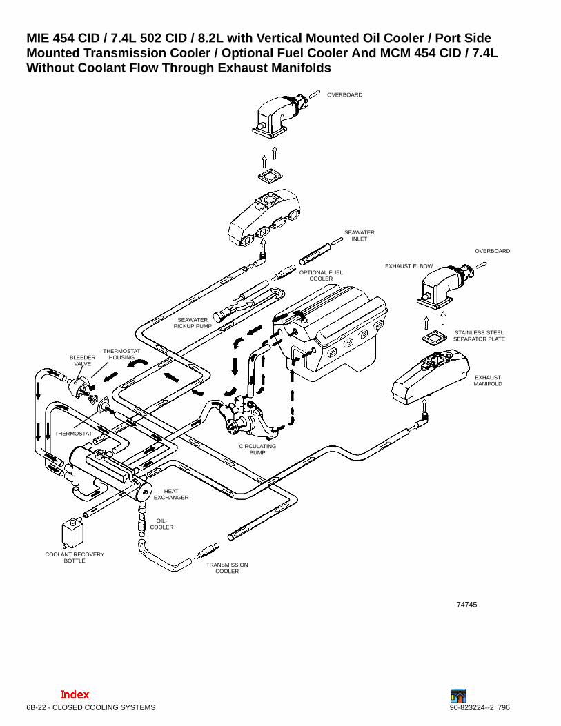
MIE 454 CID / 7.4L 502 CID / 8.2L with Vertical Mounted Oil Cooler / Port SideMounted Transmission Cooler / Optional Fuel Cooler And MCM 454 CID / 7.4LWithout Coolant Flow Through Exhaust Manifolds
74745
OVERBOARD
OVERBOARD
EXHAUST ELBOW
STAINLESS STEELSEPARATOR PLATE
EXHAUSTMANIFOLD
OIL-COOLER
SEAWATERPICKUP PUMP
SEAWATERINLET
THERMOSTAT
THERMOSTATHOUSING
COOLANT RECOVERYBOTTLE
CIRCULATINGPUMP
TRANSMISSIONCOOLER
BLEEDERVALVE
HEATEXCHANGER
OPTIONAL FUELCOOLER
THIS PAGE IS INTENTIONALLY BLANK TOALLOW FOR CORRECTIONS OR ADDITIONS
AT A LATER DATE
CLOSED COOLING SYSTEMS - 6B-2390-823324--2 796
THIS PAGE IS INTENTIONALLY BLANK TOALLOW FOR CORRECTIONS OR ADDITIONS
AT A LATER DATE
6B-24 - CLOSED COOLING SYSTEMS 90-823224--2 796