Mastercam X7 Boat Parts Solid - Cudacountry · Mastercam X7 BOAT PARTS SOLID Page 30-1 Boat Parts...
17
Mastercam X7 BOAT PARTS SOLID Page 30-1 Boat Parts Solid A. Open Boat Hull Solid File. Step 1. If necessary Open your BOAT HULL SOLID file. B. Rotate Hull. Step 1. Change to Isometric View (Alt-7). Step 2. Fit (Alt-F1). Step 3. Click down arrow of Set Planes in toolbar and click Front (WCS), Fig 1. Step 4. Change depth of your drawing. Click in Z field in Status bar at bottom of screen, key-in 0 and press ENTER. Step 5. Click Xform Menu > Rotate. Step 6. Click hull solid and click End Selection (ENTER) in ribbon bar, Fig. 2. Step 7. In Rotate dialog box set: Select Move Fig. 3 Number of Steps 1 Rotation Angle 180 Click Define Center Point . Step 8. In Auto Cursor ribbon bar set, Fig. 4 1.5 0 0 Click OK in Rotate dialog box to fix and close ribbon bar. Step 9. Right click drawing area and click Clear Colors (Alt-R C). Mastercam X7 Chapter 30 Fig. 1 Fig. 2 Fig. 3 Fig. 4 Fig. 5 Hull solid 12-9-13 © Cudacountry.net Tech Ed http://www.cudacountry.net email:[email protected]
Transcript of Mastercam X7 Boat Parts Solid - Cudacountry · Mastercam X7 BOAT PARTS SOLID Page 30-1 Boat Parts...

Mastercam X7 BOAT PARTS SOLID Page 30-1
Boat Parts SolidA. Open Boat Hull Solid File.Step 1. If necessary Open your BOAT HULL SOLID file.
B. Rotate Hull.Step 1. Change to Isometric View (Alt-7).
Step 2. Fit (Alt-F1).
Step 3. Click down arrow of Set Planes in toolbar and click Front (WCS), Fig 1.
Step 4. Change depth of your drawing. Click in Z field in Status bar at bottom of screen,
key-in 0 and press ENTER.
Step 5. Click Xform Menu > Rotate.
Step 6. Click hull solid and click End Selection (ENTER) in ribbon bar, Fig. 2.
Step 7. In Rotate dialog box set: Select Move Fig. 3
Number of Steps 1
Rotation Angle 180 Click Define Center Point .
Step 8. In Auto Cursor ribbon bar set, Fig. 4 1.5 0 0Click OK in Rotate dialog box to fix and close ribbon bar.
Step 9. Right click drawing area and click ClearColors (Alt-R C).
Mastercam X7Chapter 30
Fig. 1
Fig. 2
Fig. 3
Fig. 4
Fig. 5
Hull solid
12-9-13
© Cudacountry.net Tech Edhttp://www.cudacountry.net email:[email protected]

Mastercam X7 BOAT PARTS SOLID Page 30-2
C. Save As “BOAT PARTS SOLID”Step 1. Click File Menu > Save As.
Step 2. Key-in BOAT PARTS SOLID for the filename and press ENTER.
D. Add Parts Level.Step 1. Display Level Manager (Alt-Z).
Step 2. Key-in 5 in Number field.
Step 3. Press Tab key to move to Name Field, key-in PARTS and click OK, Fig. 6.
E. Create Base Wood Solid.Step 1. Draw wood base tangerine. Click color swatch in Status Bar at bottom of screen. Key-in
94 for tangerine color number and press ENTER (Alt-R T key-in 94 Alt-O).
Step 2. Click down arrow of Set Planes in toolbar and click Top (WCS), Fig 7.
Step 3. Click Create Menu > Primitives > Block.
Step 4. In Block dialog box set: Click Expand Fig. 8 Select Solids
Length 1.4
Width 6
Height .4 Anchor center Axis Z
Step 5. In Auto Cursor ribbon bar set: Fig. 9 1.5 5.95 .45
Step 6. Click OK in Block dialog boxto fix solid and close dialog box.
Fig. 8
Fig. 9
Fig. 7
Fig. 10
Fig. 6

Mastercam X7 BOAT PARTS SOLID Page 30-3
F. Turn Off Hull Solid Level.Step 1. Display Level Manager (Alt-Z).
Step 2. Click to remove X in Visible column of HULL SOLID level and click OK, Fig. 11.
G. Chamfer Base Solid.Step 1. Click Solids Menu > Chamfer > Two-distance
Chamfer.
Step 2. Click Select Edge in Solids Selection rib-bon bar. Fig. 12. Toggle any other Solid Selection button off.
Step 3. Click bottom front edge of base wood and front face highlights, Fig. 13.If front face highlights, click OK in Pick Reference Face dialog box, Fig. 14.If front face does not highlight, click Other Face in Pick Reference Face dialog box and click OK , Fig. 14.
Step 4. Click Select from back
in Solids Selection rib-bon bar. Fig. 15.
Step 5. Click bottom rear edge of base wood and rear face highlights, Fig. 16.If rear face highlights, click OK in Pick Refer-ence Face dialog box, Fig. 14.If rear face does not highlight, click Other Face in Pick Reference Face dialog box and click OK
, Fig. 14.
Step 6. Click End Selection (ENTER) in ribbon bar.
Step 7. In Chamfer Parameters dialog box set: Fig. 17 Distance 1 .35 Distance 2 1.3 Click OK , Fig. 17.
Fig. 12
Fig. 14
Fig. 15
Fig. 13
Select edge
Face highlights
Fig. 16
Select edgeFace
highlights
Fig. 18
Fig. 17
Fig. 11
Mastercam X7 BOAT PARTS SOLID Page 30-4
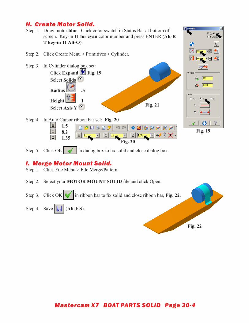
H. Create Motor Solid.Step 1. Draw motor blue. Click color swatch in Status Bar at bottom of
screen. Key-in 11 for cyan color number and press ENTER (Alt-R T key-in 11 Alt-O).
Step 2. Click Create Menu > Primitives > Cylinder.
Step 3. In Cylinder dialog box set: Click Expand Fig. 19 Select Solids
Radius .5
Height 1 Select Axis Y
Step 4. In Auto Cursor ribbon bar set: Fig. 20 1.5 8.2 1.35
Step 5. Click OK in dialog box to fix solid and close dialog box.
I. Merge Motor Mount Solid.Step 1. Click File Menu > File Merge/Pattern.
Step 2. Select your MOTOR MOUNT SOLID file and click Open.
Step 3. Click OK in ribbon bar to fix solid and close ribbon bar, Fig. 22.
Step 4. Save (Alt-F S).
Fig. 20
Fig. 21
Fig. 19
Fig. 22

Mastercam X7 BOAT PARTS SOLID Page 30-5
J. Create Battery Solid.Step 1. Draw battery yellow. Click color swatch in Status Bar at bottom of
screen. Click yellow, number 14 and click OK (Alt-R T 14 Alt-O).
Step 2. Click Create Menu > Primitives > Cylinder.
Step 3. In Cylinder dialog box set: Click Expand Fig. 23 Select Solids
Radius .25
Height 2 Select Axis Y
Step 4. In Auto Cursor ribbon bar set: Fig. 24 1.5 6.6 1.1
Step 5. Click OK in dialog box to fix solid and close dialog box.
K. Create Lines For L-Bracket.Step 1. Draw L-Bracket green. Click color swatch in Status Bar at bottom of screen. Click green,
number 44 and click OK (Alt-R T 44 Alt-O).
Step 2. Change to Right View (Alt-5).
Step 3. Click Create Menu > Line > Endpoint or Line Tool in toolbar.
Step 4. In Line ribbon bar set Length .4 and lock field Fig. 26. The field turns red when locked.
Step 5. Draw the 2 lines in Fig. 27. To draw lines, click at bottom rear of Battery to define first
point. Endpoint visual cue will appear. Snap cursor out to right horizontally and
click to define second point. Click Apply to fix entity.Click again at bottom rear of Battery for first point and snap cursor up verti-cally and click for second point. Click OK
in ribbon bar to fix line and close ribbon bar.
Fig. 24
Fig. 25
Fig. 23
Fig. 26
Fig. 27

Mastercam X7 BOAT PARTS SOLID Page 30-6
L. Fillet.Step 1. Click Create Menu > Fillet > Entities.
Step 2. Key-in .03 for Radius in Fillet ribbon bar, Fig. 28.
Step 3. Click both Lines, Fig. 29. Click OK in ribbon bar to fix.
Step 4. Save (Alt-F S).
M. Offset Contour.Step 1. Click Xform Menu > Offset Contour.
Step 2. Click Chain in Chaining dialog box, Fig. 30.
Step 3. Click any geometry of L-Bracket, Fig. 31.
Step 4. Click OK in Chaining dialog box,Fig. 30. Click OK to warning.
Step 5. Set Distance .01 in Offset Contour dialog box and press Tab key, Fig. 32.
Step 6. The purple offset should be on top of the red original, Fig. 33. If it is not, click Reverse
in Offset Contour dialog box, Fig. 32.
Step 7. Click OK in Offset Contour dialog box, Fig. 32.
Step 8. Right click drawing area and click Clear Colors (Alt-R C).
Fig. 28
Fig. 30
Fig. 32
Fig. 31
Chain geometry
Fig. 33
Fig. 29
Purpleoffset on top

Mastercam X7 BOAT PARTS SOLID Page 30-7
N. Draw Connecting Lines.Step 1. Click Create Menu > Line > Endpoint or click Line Tool in toolbar.
Step 2. In Line ribbon bar unlock Length field Fig. 34.
Step 3. Draw lines between endpoints of offset lines. Draw both lines, Fig. 35.
O. Extrude L-Bracket Solid.Step 1. Click Solids Menu > Extrude.
Step 2. Click Chain in Chaining dialog box, Fig. 30.
Step 3. Click any L-Bracket geometry, Fig. 36.
Step 4. Click OK in Chaining dialog box.
Step 5. In Extrude Chain dialog box: Select Create Body, Fig. 37 Set Distance .2 Check Both directions Click OK .
Step 6. Use Alt arrow down keys to rotate view, Fig. 38. To rotate, hold down Alt key and press down arrow key 5 times.
Fig. 35
Fig. 34
Fig. 37
Fig. 36
Chain geometry
Fig. 38

Mastercam X7 BOAT PARTS SOLID Page 30-8
P. Create Circle.Step 1. Click down arrow of Set Planes in toolbar
and click Top (WCS), Fig 39.
Step 2. Click Create Menu > Arc > Circle Center Point.
Step 3. Key-in .09 for diameter , Fig. 40. Click Diameter to lock. The field turns red when locked.
Step 4. Click midpoint on horizontal line of L-Bracket ge-
ometry, Fig. 41. Click OK to fix circle and close ribbon bar.
Step 5. Important to Save (Alt-F S).
Q. Cut Hole.Step 1. Click Solids Menu > Extrude.
Step 2. Click circle, Fig. 42.
Step 3. Click OK in Chaining dialog box.
Step 4. In Extrude dialog box, Fig. 43 Select Cut Body Select Extend through all Uncheck Reverse direction Click OK Select the L-Bracket as target body to cut, Fig. 44.
Fig. 43
Fig. 41
Fig. 39
Fig. 40
Fig. 42
Fig. 44
Chaincircle
Target body

Mastercam X7 BOAT PARTS SOLID Page 30-9
R. Chamfer Corners.Step 1. Use Alt arrow left keys to rotate view,
Fig. 45. To rotate, hold down Alt key and press left arrow key 5 times.
Step 2. Zoom-in on L-Bracket. Use F1 and make a zoom window around L-Bracket, Fig. 45.
Step 3. Turn off shading (Alt-S).
Step 4. Click Solids Menu > Chamfer > One-distance Chamfer.
Step 5. Click Select Edge and unselect the other solid select buttons in Selection ribbon bar, Fig. 46.
Step 6. Click the 4 corner edges, Fig. 47.
Step 7. Click End Selection (ENTER) in ribbon bar.
Step 8. Set Distance .07 in the Chamfer Parameters dialog box and click OK, Fig. 48 and Fig. 49.
Step 9. Turn on shading (Alt-S).
Step 10. Save (Alt-F S).
Fig. 46
Fig. 48
Zoom-In with Window
Fig. 45
Fig. 47
Fig. 49

Mastercam X7 BOAT PARTS SOLID Page 30-10
S. Set Grid and Snap .05.Step 1. Use Alt-G to display Grid dialog box, Fig. 50
Check Active grid Check Visible grid Set X and Y Spacing .05 and click OK .
T. Mirror Copy L-Bracket.Step 1. Click Xform Menu > Mirror.
Step 2. Click L-Bracket and click End Selection (ENTER) in ribbon bar, Fig. 51.
Step 3. Change to Right View (Alt-5).
Step 4. In Mirror dialog box: Select Copy , Fig. 52
Click Select two points Click 2 points on grid at X 5.6, Fig. 53. This should be in center of Battery, Fig. 54
Click OK to close Mirror dialog box.
Step 5. Right click drawing area and click Clear
Colors (Alt-R C).
Fig. 50
Fig. 51
Fig. 52
Fig. 53
Fig. 54
Fig. 55

Mastercam X7 BOAT PARTS SOLID Page 30-11
U. Turn Off Grid and Snap.Step 1. Use Alt-G to display Grid dialog box, Fig. 56
Uncheck Active grid Uncheck Visible grid Click OK .
V. Copy L-Bracket For Switch.Step 1. Change to Isometric View (Alt-7).
Step 2. Click Xform Menu > Translate.
Step 3. Click new L-Bracket to select it, Fig. 57.
Step 4. Click End Selection (ENTER) in ribbon bar.
Step 5. In Translate dialog box set: Select Copy Fig. 58 Y -.05 Click OK .
Step 6. Click All in Gen-eral Selection ribbon bar, Fig. 59.
Step 7. In Select All dialog box click Xfrom Result and click OK, Fig. 60.
Step 8. Change color of copied L-Bracket. Right click the color swatch in Status Bar at bottom of screen, Fig. 61. Key-in 9 for blue color number and press ENTER.
Step 9. Right click drawing area and click Clear Col-ors (Alt-R C).
Step 10. Save (Alt-F S).
Fig. 56
Fig. 61
Fig. 57
Fig. 58
Fig. 62
Fig. 60
Fig. 59
Right click

Mastercam X7 BOAT PARTS SOLID Page 30-12
W. Xform Move Switch Geometry.Step 1. Zoom-in on Switch. Use F1 and make a zoom window
around the Switch, Fig. 63.
Step 2. Turn off shading (Alt-S).
Step 3. Click Xform Menu > Translate.
Step 4. Click front vertical line and circle geometry of new Switch, Fig. 64.
Step 5. Click End Selection (ENTER) in ribbon bar.
Step 6. In Translate dialog box set: Select Move Fig. 65 Y -.9 Click OK , Fig. 66.
Step 7. Right click drawing area and click Clear Colors
(Alt-R C).
Fig. 63
Zoom-In withWindow
Fig. 65Fig. 64
Fig. 66

Mastercam X7 BOAT PARTS SOLID Page 30-13
X. Extend Switch Geometry Lines.Step 1. Click Edit Menu > Trim/Break > Trim/Break/Extend.
Step 2. Click the Trim 1 Entity in ribbon bar, Fig. 67.
Step 3. Extend the 2 lines that were connected to the vertical line we just moved. To extent, click horizontal line, then click vertical line, Fig. 68. Repeat and extend other horizontal line, Fig. 69.
Step 4. Click OK in ribbon bar to close ribbon bar.
Fig. 68
Fig. 67
Fig. 69
Mastercam X7 BOAT PARTS SOLID Page 30-14
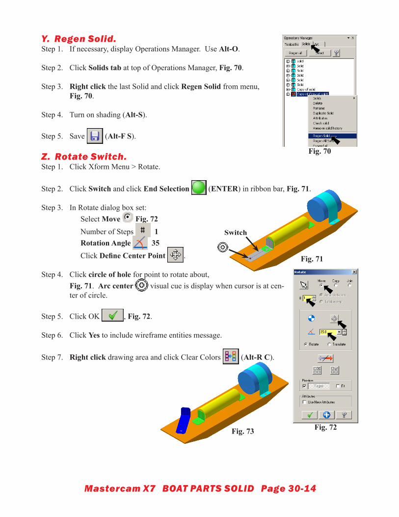
Y. Regen Solid.Step 1. If necessary, display Operations Manager. Use Alt-O.
Step 2. Click Solids tab at top of Operations Manager, Fig. 70.
Step 3. Right click the last Solid and click Regen Solid from menu,Fig. 70.
Step 4. Turn on shading (Alt-S).
Step 5. Save (Alt-F S).
Z. Rotate Switch.Step 1. Click Xform Menu > Rotate.
Step 2. Click Switch and click End Selection (ENTER) in ribbon bar, Fig. 71.
Step 3. In Rotate dialog box set: Select Move Fig. 72 Number of Steps 1 Rotation Angle 35 Click Define Center Point .
Step 4. Click circle of hole for point to rotate about, Fig. 71. Arc center visual cue is display when cursor is at cen-ter of circle.
Step 5. Click OK , Fig. 72.
Step 6. Click Yes to include wireframe entities message.
Step 7. Right click drawing area and click Clear Colors (Alt-R C).
Fig. 70
Fig. 71
Fig. 72Fig. 73
Switch

Mastercam X7 BOAT PARTS SOLID Page 30-15
AA. Create Propeller Shaft Solid.Step 1. Draw propeller shaft tan. Click color swatch in Status Bar at bottom
of screen. Key-in 55 for tan color number and press ENTER (Alt-R T 55 Alt-O).
Step 2. Click Create Menu > Primitives > Cylinder.
Step 3. In Cylinder dialog box set: Click Expand Fig. 74 Select Solids
Radius .05
Height 2 Select Axis Y
Step 4. In Auto Cursor ribbon bar set: Fig. 75 1.5 8.2 1.35
Step 5. Click Flip Direction in Cylinder dialog box until cylinder extend out rear of Mo-tor, Fig. 74 and Fig. 76.
Step 6. Click OK in dialog box to fix solid and close dialog box.
Step 7. Save (Alt-F S).
Fig. 75
Fig. 76
Fig. 74

Mastercam X7 BOAT PARTS SOLID Page 30-16
BB. Move Geometry to New Level.Step 1. Click All in General Selection ribbon
bar, Fig. 77.
Step 2. In Select All dialog box: Check Entities in criteria type, Fig. 78 Check Wireframe in criteria list and click OK.
Step 3. Right click Level in Status Bar at bottom of screen, Fig. 79.
Step 4. In Change Levels dialog box: Uncheck Use Main Level, Fig. 80 Click Select
Step 5. In Levels dialog box: Key-in 8 for Number, Fig. 81Key-in PARTS GEOMETRY for Nameclick OK.
Step 6. Click OK in Change Levels dialog box, Fig. 80.
Fig. 78
Fig. 77
Fig. 79Right click
Fig. 80
Fig. 81
Mastercam X7 BOAT PARTS SOLID Page 30-17
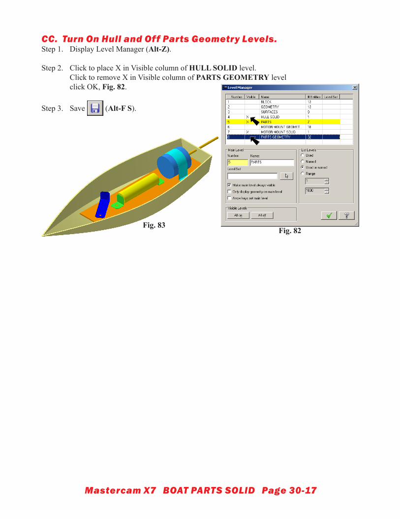
CC. Turn On Hull and Off Parts Geometry Levels.Step 1. Display Level Manager (Alt-Z).
Step 2. Click to place X in Visible column of HULL SOLID level.Click to remove X in Visible column of PARTS GEOMETRY levelclick OK, Fig. 82.
Step 3. Save (Alt-F S).
Fig. 82Fig. 83