Conversion instructions from natural gas to propane · 7 747 000 582 – 07/2006 US For heating...
24
7 747 000 582 – 07/2006 US For heating engineers Please read thoroughly before conversion Conversion instructions from natural gas to propane Gas boiler Logano GC124 II/SP This conversion kit and the accompanying instructions are for conversion of GC124 II/SP special gas-fired boilers from natural gas to propane. Requirements GC124 II/SP–18 74 MBtu/hr GC124 II/SP-25 103 MBtu/hr GC124 II/SP-32 132.5 MBtu/hr WARNING! This conversion kit must only be installed by a qualified heating contractor as specified by the manufacturer’s instructions and the applicable rules and regulations of the local authorities. If these instructions are not followed exactly, a fire, explosion or release of carbon monoxide may occur with serious property damage or loss of life and serious injury. The heating contractor is liable for correct conversion of the heating system with this conversion kit. CAUTION! Before converting the heating system to a different type of gas the gas line must first be shut off and then the power to the heating system must be disconnected. Note: Please keep these instructions for future reference.
Transcript of Conversion instructions from natural gas to propane · 7 747 000 582 – 07/2006 US For heating...

7 747 000 582 – 07/2006 US For heating engineers
Please read thoroughly before conversion
Conversion instructions from natural gas to propane
Gas boiler Logano GC124 II/SP
This conversion kit and the accompanying instructions are for conversion of GC124 II/SP special gas-fired boilers from natural gas to propane.
Requirements
GC124 II/SP–1874 MBtu/hr
GC124 II/SP-25103 MBtu/hr
GC124 II/SP-32132.5 MBtu/hr
WARNING!
This conversion kit must only be installed by a qualified heating contractor as specified by the manufacturer’s instructions and the applicable rules and regulations of the local authorities. If these instructions are not followed exactly, a fire, explosion or release of carbon monoxide may occur with serious property damage or loss of life and serious injury. The heating contractor is liable for correct conversion of the heating system with this conversion kit.
CAUTION!
Before converting the heating system to a different type of gas the gas line must first be shut off and then the power to the heating system must be disconnected.
Note: Please keep these instructions for future reference.
Contents
2 Instructions for conversion kit for gas boiler Logano GC124 II/SP • Issue 07/2006
We reserve the right to make any changes due to technical
1 Safety considerations . . . . . . . . . . . . . . . . . . . . . . . . . . . . . . . . . . . . . . . . 3
1.1 Correct use . . . . . . . . . . . . . . . . . . . . . . . . . . . . . . . . . . . . . . . . . . . . . . . 3
1.2 Observe the following symbols . . . . . . . . . . . . . . . . . . . . . . . . . . . . . . . . . . . 3
1.3 Observe the following guidelines. . . . . . . . . . . . . . . . . . . . . . . . . . . . . . . . . . 3
2 Scope of delivery . . . . . . . . . . . . . . . . . . . . . . . . . . . . . . . . . . . . . . . . . . . . 3
3 Conversion to propane . . . . . . . . . . . . . . . . . . . . . . . . . . . . . . . . . . . . . . . 4
4 Start-up instructions . . . . . . . . . . . . . . . . . . . . . . . . . . . . . . . . . . . . . . . . . 9
4.1 Starting up the GC124 II and GC124 SP boilers . . . . . . . . . . . . . . . . . . . . . . . 10
5 Final start-up procedures for GC124 II models . . . . . . . . . . . . . . . . . . . . 11
6 Final start-up procedure for GC124 SP models . . . . . . . . . . . . . . . . . . . . 16

Safety considerations 1
3
We reserve the right to make any changes due to technical modifications.
Instructions for conversion kit for gas boiler Logano GC124 II/SP • Issue 07/2006
1 Safety considerations
Observe these instructions for your safety.
1.1 Correct use
The conversion set is supplied for conversion of the GC124II/SP special gas-fired boiler from natural gas to propane.
1.2 Observe the following symbols
Additional symbols for identification of dangers and user instructions.
1.3 Observe the following guidelines
2 Scope of delivery
1. Honeywell gas solenoid valve conversion kit # 393 691, comprising:
– black safety screw
– pressure adjustment screw
– red spring
– yellow label for gas valve
2. For GC124 II: BBR 12 pilot gas orificeGC124 SP only: GAF 8 pilot gas orifice
3. Main gas orifices and seals
4. "Conversion to propane" label (to be filled out and attached to the unit)
5. Technical documents
WARNING!
RISK TO LIFE
Identifies possible dangers originating from the product, which might lead to serious injury or death if proper care is not taken.
WARNING!
RISK TO LIFE
from electric shock.
USER NOTE
Guidelines for the optimum use and setting of the control(s) plus other useful information.
WARNING!
RISK TO LIFE
through the explosion of volatile gases.
Work on gas components must be carried out by qualified and authorized personnel only.
WARNING!
RISK TO LIFE
from electric shock.
Disconnect the power supply to the heating system before conducting any work on it, e.g. switch off the heating emergency switch outside the boiler room.
It is not sufficient just to switch off the control.

Conversion to propane3
3 Conversion to propane
For your own safety read the instructions before conversion.
The following instructions must be followed for conversion of the boiler to propane:
1. If the boiler was in operation, close the gas shut-off. Otherwise continue with step 4.
2. Set room thermostat (optional) to the lowest value.
3. Disconnect the heating system from the power supply.
4. Open boiler front door.
WARNING!
RISK TO LIFE
through not observing the conversion instructions.
If you wish to convert the boiler for operation with propane, the conversion from natural gas to propane must be carried out first as specified by the attached conversion instructions.
Fig. 1 Opening boiler front door
4 Instructions for conversion kit for gas boiler Logano GC124 II/SP • Issue 07/2006
We reserve the right to make any changes due to technical
Conversion to propane 3
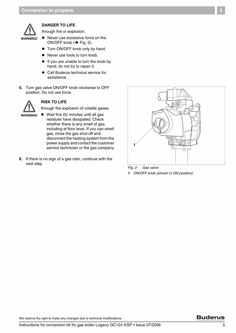
5. Turn gas valve ON/OFF knob clockwise to OFF position. Do not use force.
6. If there is no sign of a gas odor, continue with the next step.
WARNING!
DANGER TO LIFE
through fire or explosion.
Never use excessive force on the ON/OFF knob ( Fig. 2).
Turn ON/OFF knob only by hand.
Never use tools to turn knob.
If you are unable to turn the knob by hand, do not try to repair it.
Call Buderus technical service for assistance.
Fig. 2 Gas valve
1 ON/OFF knob (shown in ON position)
1
WARNING!
RISK TO LIFE
through the explosion of volatile gases.
Wait five (5) minutes until all gas residues have dissipated. Check whether there is any smell of gas, including at floor level. If you can smell gas, close the gas shut-off and disconnect the heating system from the power supply and contact the customer service technician or the gas company.
5
We reserve the right to make any changes due to technical modifications.
Instructions for conversion kit for gas boiler Logano GC124 II/SP • Issue 07/2006

Conversion to propane3
Removing burner
7. Secure gas manifold with wire or cord.
8. GC124 II only: Remove igniter cable from ignition module ( Fig. 3).
9. Disconnect cable connector from bottom of gas valve ( Fig. 3).
10. Label cables to the flame roll-out switch, then remove cable ( Fig. 3).
Fig. 3 Front view (GC124 II top, GC124 SP bottom)
1 Flame roll-out switch2 Flame roll-out switch cable
3 Gas valve
4 Gas supply pipe5 Aquastat
6 Ignition module (GC124 II only)
7 Igniter cable (GC124 II only)8 Gas valve cable connector
9 Pilot line
10 Igniter cable (GC124 II only) or thermocouple cable (GC124 SP only)
GC124 II
GC124 SP
1
10
4
98
2
7
5
6
3
2 1
3
4
5
89
10
6 Instructions for conversion kit for gas boiler Logano GC124 II/SP • Issue 07/2006
We reserve the right to make any changes due to technical
Conversion to propane 3
11. Remove four (4) screws from gas manifold on top of gas valve.
12. Remove two (2) screw nuts on burner tray and take out the tray.
Replacing main gas orifices
13. Install the new main gas orifices and copper gasket. Check with Tab. 1 that the correct orifices for operation of the boiler are installed.
Converting gas valve
14. Remove the safety screw ( Fig. 5) for the manifold pressure adjustment on the gas valve.
15. Remove manifold pressure adjustment screw ( Fig. 5).
16. Remove stainless steel spiral spring ( Fig. 5).
17. Install the red spring from the Honeywell conversion kit in the gas valve.
18. Screw in the new gas adjustment screw from the Honeywell conversion kit until it is flush with the top of the gas valve.Then screw the manifold pressure adjustment screw six (6) revolutions clockwise. This corresponds to a pressure preset of approx. 10.0 W.C. This setting must be checked with a pressure gauge on completion of the conversion.( Chapter 4, page 9).
19. Install new black safety screw from the Honeywell conversion kit.
20. Clean the gas valve housing ( Fig. 5) and attach the yellow label from the Honeywell LP conversion kit to a visible spot on the gas valve.
Fig. 4 Removing burner (GC124 SP shown)
1 Screw nuts (two)2 Screws on gas manifold on top of gas valve (four)
2
1
USER NOTE
These orifice sizes are exclusively for installations 0-8500 feet above sea level.
Orifice sizes for propane
Model GC124-18 GC124-25 GC124-32
Orifice size 180 175 170
Qty. 2 3 4
Tab. 1 Orifice sizes for propaneThese values are applicable for the U.S.A. only.for altitudes of 0 - 8500 ft.
Fig. 5 Gas valve on the GC124 II
1 Safety screw
2 Manifold pressure adjustment screw
3 Stainless steel spiral spring4 Gas valve
5 Yellow label
1
2 3
4
5
7
We reserve the right to make any changes due to technical modifications.
Instructions for conversion kit for gas boiler Logano GC124 II/SP • Issue 07/2006

Conversion to propane3
Removing pilot burner and replacing pilot gas orifice
21. Unscrew ignition burner unit from burner.
22. Remove pilot orifice.
23. Position the new BBR 12 pilot gas orifice for the GC124 II or the new GAF 8 pilot gas orifice for the GC124 SP in pilot burner unit.
24. Screw the pilot line to the pilot burner unit.
25. Screw the pilot burner unit to the main burner.
26. Check that the pilot burner unit is correctly seated compared to the main burner.
27. Record the required information on theconversion label and attach on the outside of the boiler jacket as close as possible to the nameplate.
Carrying out leak test
28. Open manual gas shut-off in the gas line.
29. Check the gas supply line to the gas shut-off for leaks with soap solution. If no leaks are found, continue with step 31. If any leaks were found, close gas shut-off.
30. Seal leaks and repeat step 29.
31. Wait five (5) minutes until all gas residues have dissipated. Then check for a gas odor, including at floor level, because many types of gas are heavier than air.
32. Always follow the start-up instructions on the next page.
Fig. 6 Pilot burner (GC124 II left, GC124 SP right)
1 Ignition cable2 Ignition electrode
3 Pilot gas line
4 Pilot gas line retaining screws
1
33
2
44
USER NOTE
When installing the pilot gas orifice, make sure that the pilot gas orifice is correctly threaded and tightened.
8 Instructions for conversion kit for gas boiler Logano GC124 II/SP • Issue 07/2006
We reserve the right to make any changes due to technical

Start-up instructions 4
4 Start-up instructions
For your own safety, read before boiler start-up.
WARNING!
RISK TO LIFE
due to not observing the start-up instructions and resulting malfunction.
If these instructions are not followed exactly, fire or explosion may result causing serious property damage, loss of life, or serious personal injury.
Observe the installation instructions.
WARNING!
DANGER OF EXPLOSION
If you smell gas there is danger of explosion!
No open flame! No smoking!
Prevent spark generation. Never operate electrical switches, including telephones, plugs or door bells!
Close main gas shut-off!
Open windows and doors!
Warn all occupants of the building!
Evacuate the building!
Call gas company, heating contractor or fire department from outside the building.
USER NOTICE
GC124 II only:
This unit is equipped with an automatic igniter that starts the burner. Do not attempt to ignite the burner manually.
GC124 SP only:
This unit is equipped with a burner that must be ignited manually. Follow the instructions below to ignite the standing pilot burner Chapter 6, page 16.
WARNING!
RISK TO LIFE
due to water damage.
Do not operate the unit if any part is or was submerged in water.
Contact a qualified customer service technician immediately to have the unit checked and all parts of the control and gas valves replaced that were in contact with water.
9
We reserve the right to make any changes due to technical modifications.
Instructions for conversion kit for gas boiler Logano GC124 II/SP • Issue 07/2006
Start-up instructions4
4.1 Starting up the GC124 II and GC124 SP boilers
1. STOP! First perform a leak test as described on page 8 of this manual.
2. First read the safety instructions on page 9 of this manual.
4.1.1 Prepare pressure measurement
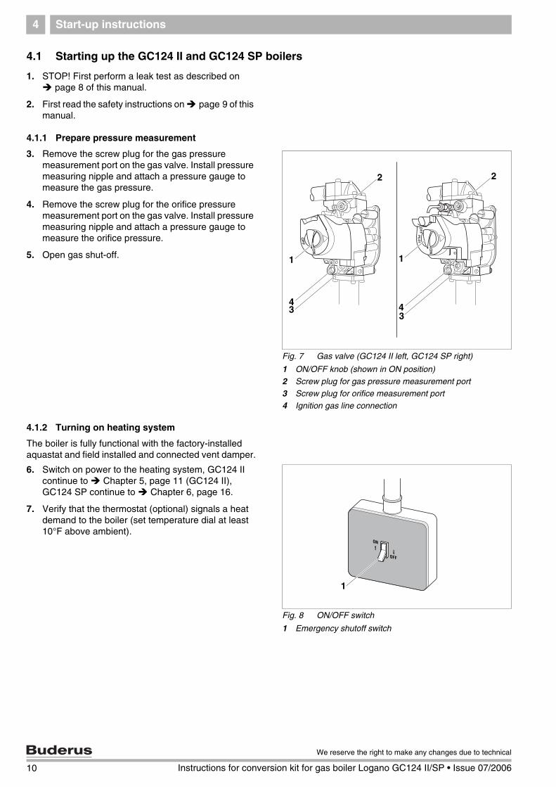
3. Remove the screw plug for the gas pressure measurement port on the gas valve. Install pressure measuring nipple and attach a pressure gauge to measure the gas pressure.
4. Remove the screw plug for the orifice pressure measurement port on the gas valve. Install pressure measuring nipple and attach a pressure gauge to measure the orifice pressure.
5. Open gas shut-off.
4.1.2 Turning on heating system
The boiler is fully functional with the factory-installed aquastat and field installed and connected vent damper.
6. Switch on power to the heating system, GC124 II continue to Chapter 5, page 11 (GC124 II), GC124 SP continue to Chapter 6, page 16.
7. Verify that the thermostat (optional) signals a heat demand to the boiler (set temperature dial at least 10°F above ambient).
Fig. 7 Gas valve (GC124 II left, GC124 SP right)
1 ON/OFF knob (shown in ON position)
2 Screw plug for gas pressure measurement port3 Screw plug for orifice measurement port
4 Ignition gas line connection
1
2
34
1
2
34
Fig. 8 ON/OFF switch
1 Emergency shutoff switch
1
10 Instructions for conversion kit for gas boiler Logano GC124 II/SP • Issue 07/2006
We reserve the right to make any changes due to technical

Final start-up procedures for GC124 II models 5
5 Final start-up procedures for GC124 II models
Verifying the ignition spark
1. Look through the sight glass at the igniter and verify that a spark is visible.
2. Should no spark be visible continue to troubleshooting procedure in the installation and service manual.
3. Turn ON/OFF knob ( Fig. 10) counterclockwise to the ON position.
4. The ignition flame will appear and ignite the main burner. If the main burner does not ignite, close the gas shut-off. Disconnect heating system from the power source and inform your customer service technician or gas company.
Fig. 9 GC124 II boile
1 Sight glass
1
Fig. 10 GC124 II gas valve
1 ON/OFF knob (shown in ON position)
1
WARNING!
RISK TO LIFE
from fire or explosion.
Never use excessive force on the ON/OFF knob ( Fig. 10).
Turn ON/OFF knob only by hand.
Never use tools to turn knob.
If you are unable to turn the knob by hand, do not try to repair it.
Call Buderus technical service for assistance.
11
We reserve the right to make any changes due to technical modifications.
Instructions for conversion kit for gas boiler Logano GC124 II/SP • Issue 07/2006
Final start-up procedures for GC124 II models5
Checking gas supply pressure
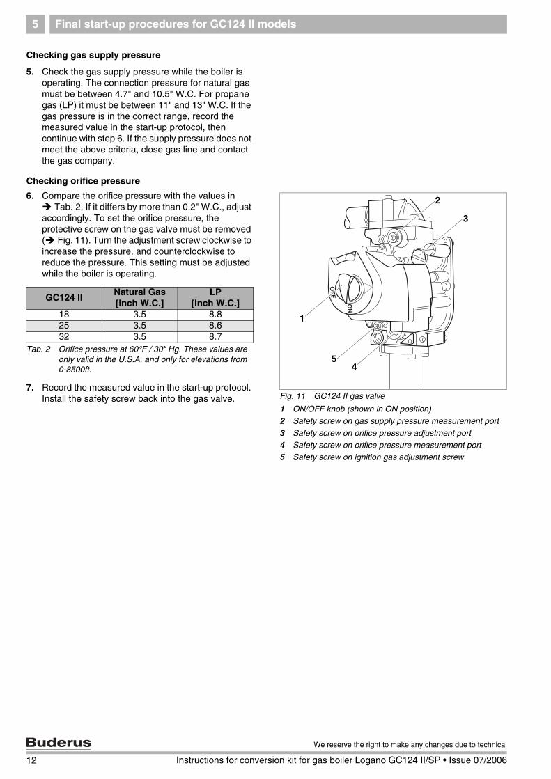
5. Check the gas supply pressure while the boiler is operating. The connection pressure for natural gas must be between 4.7" and 10.5" W.C. For propane gas (LP) it must be between 11" and 13" W.C. If the gas pressure is in the correct range, record the measured value in the start-up protocol, then continue with step 6. If the supply pressure does not meet the above criteria, close gas line and contact the gas company.
Checking orifice pressure
6. Compare the orifice pressure with the values in Tab. 2. If it differs by more than 0.2" W.C., adjust
accordingly. To set the orifice pressure, the protective screw on the gas valve must be removed ( Fig. 11). Turn the adjustment screw clockwise to increase the pressure, and counterclockwise to reduce the pressure. This setting must be adjusted while the boiler is operating.
7. Record the measured value in the start-up protocol. Install the safety screw back into the gas valve. Fig. 11 GC124 II gas valve
1 ON/OFF knob (shown in ON position)
2 Safety screw on gas supply pressure measurement port
3 Safety screw on orifice pressure adjustment port4 Safety screw on orifice pressure measurement port
5 Safety screw on ignition gas adjustment screw
1
2
45
3
GC124 IINatural Gas[inch W.C.]
LP[inch W.C.]
18 3.5 8.825 3.5 8.632 3.5 8.7
Tab. 2 Orifice pressure at 60°F / 30" Hg. These values are only valid in the U.S.A. and only for elevations from 0-8500ft.
12 Instructions for conversion kit for gas boiler Logano GC124 II/SP • Issue 07/2006
We reserve the right to make any changes due to technical
Final start-up procedures for GC124 II models 5
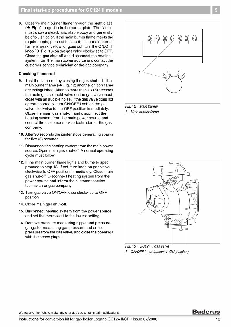
8. Observe main burner flame through the sight glass ( Fig. 9, page 11) in the burner plate. The flame must show a steady and stable body and generally be of bluish color. If the main burner flame meets the requirements, proceed to step 9. If the main burner flame is weak, yellow, or goes out, turn the ON/OFF knob ( Fig. 13) on the gas valve clockwise to OFF. Close the gas shut-off and disconnect the heating system from the main power source and contact the customer service technician or the gas company.
Checking flame rod
9. Test the flame rod by closing the gas shut-off. The main burner flame ( Fig. 12) and the ignition flame are extinguished. After no more than six (6) seconds the main gas solenoid valve on the gas valve must close with an audible noise. If the gas valve does not operate correctly, turn ON/OFF knob on the gas valve clockwise to the OFF position immediately. Close the main gas shut-off and disconnect the heating system from the main power source and contact the customer service technician or the gas company.
10. After 90 seconds the igniter stops generating sparks for five (5) seconds.
11. Disconnect the heating system from the main power source. Open main gas shut-off. A normal operating cycle must follow.
12. If the main burner flame lights and burns to spec, proceed to step 13. If not, turn knob on gas valve clockwise to OFF position immediately. Close main gas shut-off. Disconnect heating system from the power source and inform the customer service technician or gas company.
13. Turn gas valve ON/OFF knob clockwise to OFF position.
14. Close main gas shut-off.
15. Disconnect heating system from the power source and set the thermostat to the lowest setting.
16. Remove pressure measuring nipple and pressure gauge for measuring gas pressure and orifice pressure from the gas valve, and close the openings with the screw plugs.
Fig. 12 Main burner
1 Main burner flame
1
Fig. 13 GC124 II gas valve
1 ON/OFF knob (shown in ON position)
1
13
We reserve the right to make any changes due to technical modifications.
Instructions for conversion kit for gas boiler Logano GC124 II/SP • Issue 07/2006
Final start-up procedures for GC124 II models5
Checking for leaks
17. Open main gas shut-off.
18. Set thermostat at least 10°F above ambient to establish a heat demand.
19. Turn main power switch ON.
20. Turn gas valve ON/OFF knob counterclockwise to ON position.
21. After the burner has lit check the gas valve including screw plugs for leaks using soapy water. If no leaks are found, continue with step 23. If leaks are found, close gas shut-off and turn ON/OFF knob on gas valve clockwise to the OFF position. Disconnect the heating system from the power source and turn thermostat to its lowest setting.
22. Seal leaks. Repeat steps 17 to 21.
23. Carefully wipe away the soapy water to prevent corrosion caused by the alkaline content of the soap.
Checking the vent damper
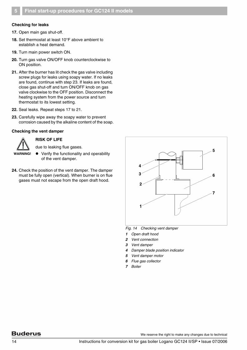
24. Check the position of the vent damper. The damper must be fully open (vertical). When burner is on flue gases must not escape from the open draft hood.
Fig. 14 Checking vent damper
1 Open draft hood
2 Vent connection3 Vent damper
4 Damper blade position indicator
5 Vent damper motor6 Flue gas collector
7 Boiler
5
6
7
4
3
1
2
WARNING!
RISK OF LIFE
due to leaking flue gases.
Verify the functionality and operability of the vent damper.
14 Instructions for conversion kit for gas boiler Logano GC124 II/SP • Issue 07/2006
We reserve the right to make any changes due to technical
Final start-up procedures for GC124 II models 5
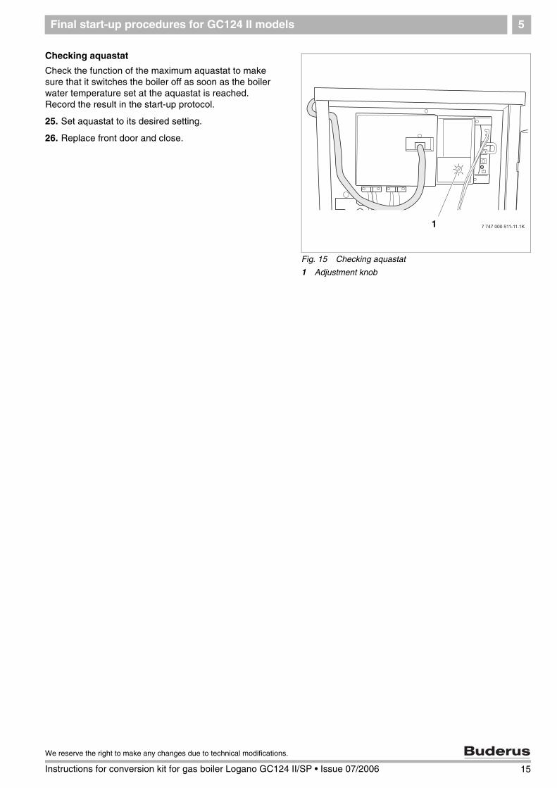
Checking aquastat
Check the function of the maximum aquastat to make sure that it switches the boiler off as soon as the boiler water temperature set at the aquastat is reached. Record the result in the start-up protocol.
25. Set aquastat to its desired setting.
26. Replace front door and close.
Fig. 15 Checking aquastat
1 Adjustment knob
1
15
We reserve the right to make any changes due to technical modifications.
Instructions for conversion kit for gas boiler Logano GC124 II/SP • Issue 07/2006
Final start-up procedure for GC124 SP models6
6 Final start-up procedure for GC124 SP models
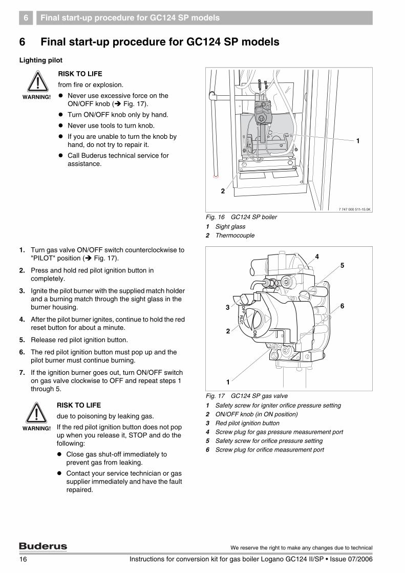
Lighting pilot
1. Turn gas valve ON/OFF switch counterclockwise to "PILOT" position ( Fig. 17).
2. Press and hold red pilot ignition button in completely.
3. Ignite the pilot burner with the supplied match holder and a burning match through the sight glass in the burner housing.
4. After the pilot burner ignites, continue to hold the red reset button for about a minute.
5. Release red pilot ignition button.
6. The red pilot ignition button must pop up and the pilot burner must continue burning.
7. If the ignition burner goes out, turn ON/OFF switch on gas valve clockwise to OFF and repeat steps 1 through 5.
Fig. 16 GC124 SP boiler
1 Sight glass2 Thermocouple
1
2
WARNING!
RISK TO LIFE
from fire or explosion.
Never use excessive force on the ON/OFF knob ( Fig. 17).
Turn ON/OFF knob only by hand.
Never use tools to turn knob.
If you are unable to turn the knob by hand, do not try to repair it.
Call Buderus technical service for assistance.
Fig. 17 GC124 SP gas valve
1 Safety screw for igniter orifice pressure setting
2 ON/OFF knob (in ON position)
3 Red pilot ignition button4 Screw plug for gas pressure measurement port
5 Safety screw for orifice pressure setting
6 Screw plug for orifice measurement port
2
4
6
1
5
3
WARNING!
RISK TO LIFE
due to poisoning by leaking gas.
If the red pilot ignition button does not pop up when you release it, STOP and do the following:
Close gas shut-off immediately to prevent gas from leaking.
Contact your service technician or gas supplier immediately and have the fault repaired.
16 Instructions for conversion kit for gas boiler Logano GC124 II/SP • Issue 07/2006
We reserve the right to make any changes due to technical
Final start-up procedure for GC124 SP models 6
8. If the ignition burner continues to go out after several attempts, turn the ON/OFF knob on the gas valve to OFF immediately to prevent gas from leaking. Check ignition gas line for leaks with soapy water. If no leaks are found, continue with step 9. If leaks have been found, turn ON/OFF knob on gas valve ( Fig. 18) clockwise to the "OFF" position.
9. Seal leaks. Repeats steps 1 to 8.
10. The gas valve ON/OFF knob ( Fig. 18) can only be set to ON if the red pilot ignition button is out. Turn main power switch of the heating system ON.
11. Verify that the thermal element responds to heat.
12. The ignition flame must ignite the main burner. If the main burner does not ignite, close the gas shut-off. Disconnect heating system from the power source and inform your customer service technician or gas company.
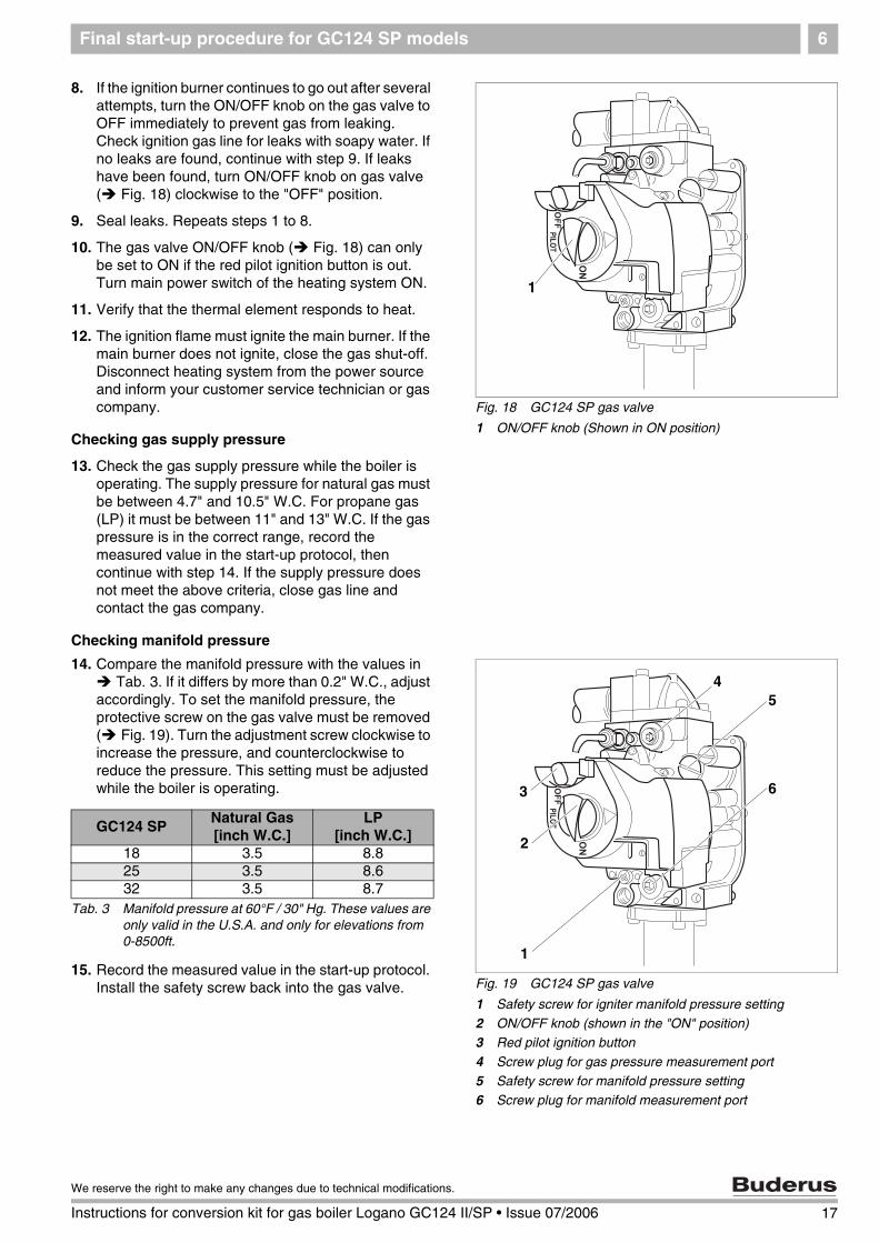
Checking gas supply pressure
13. Check the gas supply pressure while the boiler is operating. The supply pressure for natural gas must be between 4.7" and 10.5" W.C. For propane gas (LP) it must be between 11" and 13" W.C. If the gas pressure is in the correct range, record the measured value in the start-up protocol, then continue with step 14. If the supply pressure does not meet the above criteria, close gas line and contact the gas company.
Checking manifold pressure
14. Compare the manifold pressure with the values in Tab. 3. If it differs by more than 0.2" W.C., adjust
accordingly. To set the manifold pressure, the protective screw on the gas valve must be removed ( Fig. 19). Turn the adjustment screw clockwise to increase the pressure, and counterclockwise to reduce the pressure. This setting must be adjusted while the boiler is operating.
15. Record the measured value in the start-up protocol. Install the safety screw back into the gas valve.
Fig. 18 GC124 SP gas valve
1 ON/OFF knob (Shown in ON position)
1
Fig. 19 GC124 SP gas valve
1 Safety screw for igniter manifold pressure setting
2 ON/OFF knob (shown in the "ON" position)3 Red pilot ignition button
4 Screw plug for gas pressure measurement port
5 Safety screw for manifold pressure setting6 Screw plug for manifold measurement port
2
4
6
1
5
3
GC124 SPNatural Gas[inch W.C.]
LP[inch W.C.]
18 3.5 8.825 3.5 8.632 3.5 8.7
Tab. 3 Manifold pressure at 60°F / 30" Hg. These values are only valid in the U.S.A. and only for elevations from 0-8500ft.
17
We reserve the right to make any changes due to technical modifications.
Instructions for conversion kit for gas boiler Logano GC124 II/SP • Issue 07/2006
Final start-up procedure for GC124 SP models6
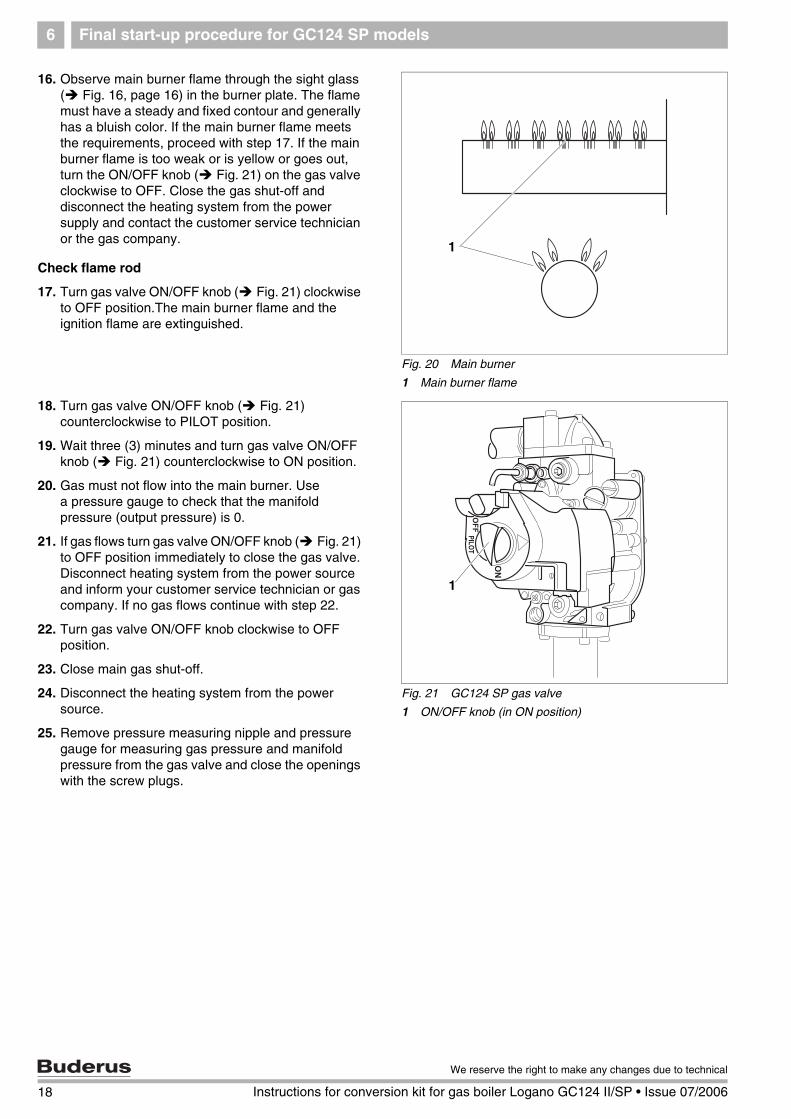
16. Observe main burner flame through the sight glass( Fig. 16, page 16) in the burner plate. The flame must have a steady and fixed contour and generally has a bluish color. If the main burner flame meets the requirements, proceed with step 17. If the main burner flame is too weak or is yellow or goes out, turn the ON/OFF knob ( Fig. 21) on the gas valve clockwise to OFF. Close the gas shut-off and disconnect the heating system from the power supply and contact the customer service technician or the gas company.
Check flame rod
17. Turn gas valve ON/OFF knob ( Fig. 21) clockwise to OFF position.The main burner flame and the ignition flame are extinguished.
18. Turn gas valve ON/OFF knob ( Fig. 21) counterclockwise to PILOT position.
19. Wait three (3) minutes and turn gas valve ON/OFF knob ( Fig. 21) counterclockwise to ON position.
20. Gas must not flow into the main burner. Use a pressure gauge to check that the manifold pressure (output pressure) is 0.
21. If gas flows turn gas valve ON/OFF knob ( Fig. 21) to OFF position immediately to close the gas valve. Disconnect heating system from the power source and inform your customer service technician or gas company. If no gas flows continue with step 22.
22. Turn gas valve ON/OFF knob clockwise to OFF position.
23. Close main gas shut-off.
24. Disconnect the heating system from the power source.
25. Remove pressure measuring nipple and pressure gauge for measuring gas pressure and manifold pressure from the gas valve and close the openings with the screw plugs.
Fig. 20 Main burner
1 Main burner flame
1
Fig. 21 GC124 SP gas valve
1 ON/OFF knob (in ON position)
1
18 Instructions for conversion kit for gas boiler Logano GC124 II/SP • Issue 07/2006
We reserve the right to make any changes due to technical
Final start-up procedure for GC124 SP models 6
Carrying out leak test
26. Open main gas shut-off.
27. Set thermostat at least 10°F above ambient to establish a heat demand.
28. Turn on ON/OFF switch (Emergency shutoff switch).
29. Repeat steps 1 to 5 on page 16.
30. After the burner has lit check the gas valve including screw plugs for leaks using soapy water. If no leaks are found, continue with step 32. If leaks are found, close gas valve and turn ON/OFF knob on gas valve clockwise to the OFF position. Disconnect the heating system from the power source and turn thermostat to its lowest setting.
31. Seal any leaks. Repeat steps 26 to 30.
32. Carefully wipe away the soapy water to prevent corrosion caused by the alkaline content of the soap.
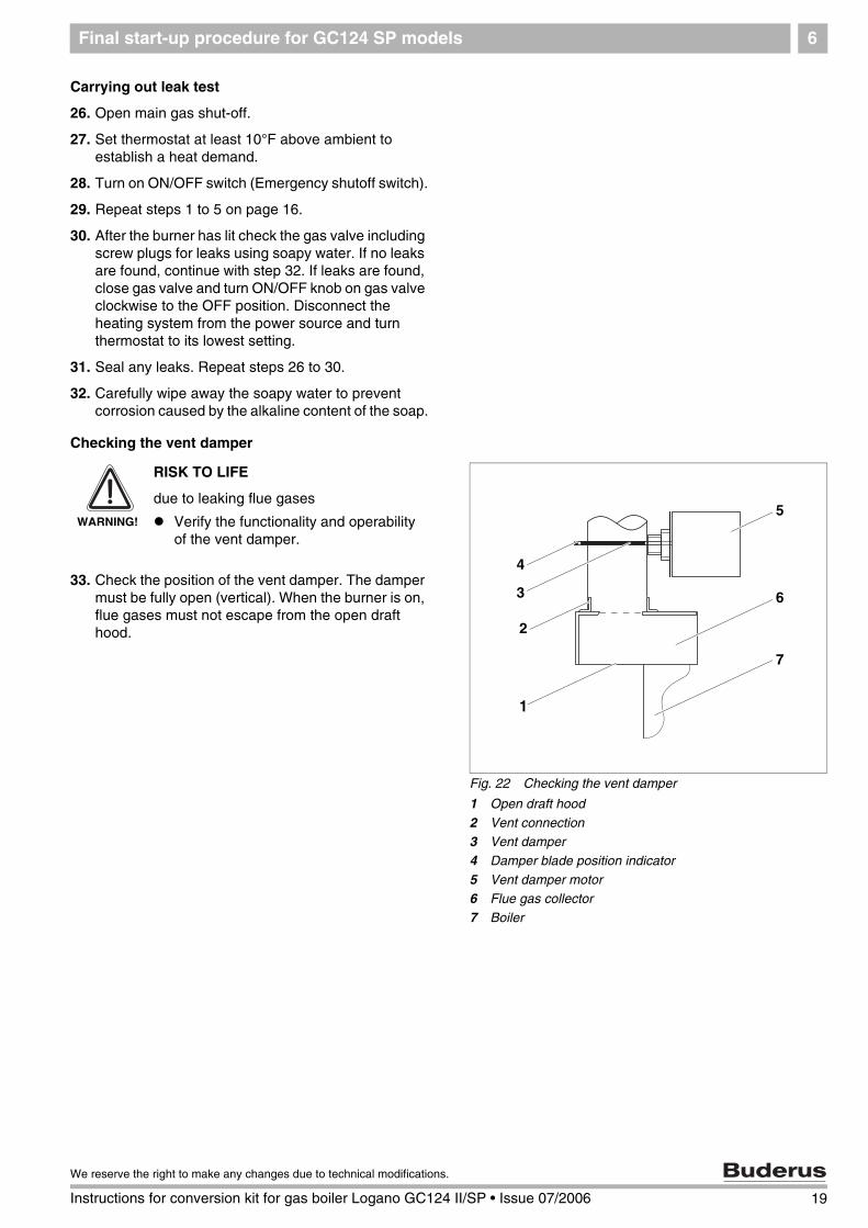
Checking the vent damper
33. Check the position of the vent damper. The damper must be fully open (vertical). When the burner is on, flue gases must not escape from the open draft hood.
Fig. 22 Checking the vent damper
1 Open draft hood
2 Vent connection3 Vent damper
4 Damper blade position indicator
5 Vent damper motor6 Flue gas collector
7 Boiler
5
6
7
4
3
1
2
WARNING!
RISK TO LIFE
due to leaking flue gases
Verify the functionality and operability of the vent damper.
19
We reserve the right to make any changes due to technical modifications.
Instructions for conversion kit for gas boiler Logano GC124 II/SP • Issue 07/2006

Final start-up procedure for GC124 SP models6
Checking the Aquastat
Check the function of the maximum aquastat to make sure that it switches the boiler off as soon as the boiler water temperature set at the aquastat is reached. Record the result in the start-up protocol.
34. Set the aquastat to its desired setting.
35. Replace front door and close.
Fig. 23 Checking aquastat
1 Adjustment knob
1
20 Instructions for conversion kit for gas boiler Logano GC124 II/SP • Issue 07/2006
We reserve the right to make any changes due to technical

Final start-up procedure for GC124 SP models 6
21
We reserve the right to make any changes due to technical modifications.
Instructions for conversion kit for gas boiler Logano GC124 II/SP • Issue 07/2006

Notes
22 Instructions for conversion kit for gas boiler Logano GC124 II/SP • Issue 07/2006
We reserve the right to make any changes due to technical

Notes
23
We reserve the right to make any changes due to technical modifications.
Instructions for conversion kit for gas boiler Logano GC124 II/SP • Issue 07/2006

Your installer:
BBT Thermotechnik GmbH, D-35573 [email protected]
BBT North America Corporation - Bosch Group 50 Wentworth Ave
Londonderry, New Hampshire 03053 USA Tel: (603) 552-1100/800-Buderus Fax: (603) 421-2719
www.buderus.net