Installation Instructions -...
12
1 KGANP4901AAA Installation Instructions Gas Conversion Kit Natural---to---Propane ECM X 2---Stage and Single---Stage 90% Condensing Gas Furnaces D E S I G N C E R T I F I E D CERTIFIED TABLE OF CONTENTS PAGE Safety Considerations 1 .............................. Introduction 2 ...................................... Description and Usage 2 .............................. Install Main Burner Orifices 2 .......................... Install Diverter Plate (Two Stage Models Only) 3 ........... Convert Main Gas Valve 4 ............................ Convert Two--Stage Gas Valve 4 .................... Convert Single Stage Gas Valve 4 ................... Install Low Gas Pressure Switch 5 ...................... Reinstall Manifold Assembly 6 ......................... Modify Pressure Switch Wiring 6 ....................... Two--Stage Furnaces 6 ............................ Single Stage Furnace 6 ............................ Gas Input Rate Information 8 .......................... Connect Manometer to Manifold Pressure Tap 8 ........... Set Gas Input Rate / Adjust Manifold Pressure 9 ........... Two--Stage Furnaces 9 ............................ Single Stage Furnace 9 ............................ Check Low Gas Pressure Switch Operation 10 ............. Label Application 11 ................................ NOTE: Read the entire instruction manual before starting the installation. SAFETY CONSIDERATIONS Installing and servicing heating equipment can be hazardous due to gas and electrical components. Only trained and qualified personnel should install, repair, or service heating equipment. Untrained personnel can perform basic maintenance functions such as cleaning and replacing air filters. Trained service personnel must perform all other operations. When working on heating equipment, observe precautions in the literature, on tags, and on labels attached to or shipped with the unit, and other safety precautions that may apply. Follow all safety codes. In the United States, follow all safety codes including the current edition of the National Fuel Gas Code (NFGC) NFPA 54/ANSI Z223.1. In Canada, refer to the National Standard of Canada, Natural Gas and Propane Installation Codes (NSCNGPIC), CAN/CGA--B149.1 and .2. Wear safety glasses and work gloves. Have a fire extinguisher available during start--up, adjustment steps, and service calls. Recognize safety information. This is the safety--alert symbol . When you see this symbol on the furnace and in instructions or manuals, be alert to the potential for personal injury. Understand the signal words DANGER, WARNING, CAUTION and NOTE. These words are used with the safety--alert symbol. DANGER identifies the most serious hazards which will result in severe personal injury or death. WARNING signifies a hazard which could result in personal injury or death. CAUTION is used to identify unsafe practices which may result in minor personal injury or product and property damage. NOTE is used to highlight suggestions which will result in enhanced installation, reliability, or operation. FIRE, EXPLOSION, ELECTRICAL SHOCK, AND CARBON MONOXIDE POISONING HAZARD Failure to follow this warning could result in personal injury or death. This conversion kit shall be installed by a qualified service agency in accordance with the manufacturer’s instructions and all applicable codes and requirements of the authority having jurisdiction. If the information in these instructions is not followed exactly, a fire, explosion, or production of carbon monoxide may result causing property damage, personal injury, or loss of life. The qualified service agency is responsible for the proper installation of this furnace with this kit. The installation is not proper and complete until the operation of the converted appliance is checked as specified in the manufacturer’s instructions supplied with the kit. ! WARNING
Transcript of Installation Instructions -...

1
KGANP4901AAA
Installation Instructions
Gas Conversion Kit Natural---to---Propane
ECM X 2---Stage and Single---Stage 90%
Condensing Gas Furnaces
D E S I G N
C E R T I F I E DCERTIFIED
TABLE OF CONTENTS PAGE
Safety Considerations 1. . . . . . . . . . . . . . . . . . . . . . . . . . . . . .
Introduction 2. . . . . . . . . . . . . . . . . . . . . . . . . . . . . . . . . . . . . .
Description and Usage 2. . . . . . . . . . . . . . . . . . . . . . . . . . . . . .
Install Main Burner Orifices 2. . . . . . . . . . . . . . . . . . . . . . . . . .
Install Diverter Plate (Two Stage Models Only) 3. . . . . . . . . . .
Convert Main Gas Valve 4. . . . . . . . . . . . . . . . . . . . . . . . . . . .
Convert Two--Stage Gas Valve 4. . . . . . . . . . . . . . . . . . . .
Convert Single Stage Gas Valve 4. . . . . . . . . . . . . . . . . . .
Install Low Gas Pressure Switch 5. . . . . . . . . . . . . . . . . . . . . .
Reinstall Manifold Assembly 6. . . . . . . . . . . . . . . . . . . . . . . . .
Modify Pressure Switch Wiring 6. . . . . . . . . . . . . . . . . . . . . . .
Two--Stage Furnaces 6. . . . . . . . . . . . . . . . . . . . . . . . . . . .
Single Stage Furnace 6. . . . . . . . . . . . . . . . . . . . . . . . . . . .
Gas Input Rate Information 8. . . . . . . . . . . . . . . . . . . . . . . . . .
Connect Manometer to Manifold Pressure Tap 8. . . . . . . . . . .
Set Gas Input Rate / Adjust Manifold Pressure 9. . . . . . . . . . .
Two--Stage Furnaces 9. . . . . . . . . . . . . . . . . . . . . . . . . . . .
Single Stage Furnace 9. . . . . . . . . . . . . . . . . . . . . . . . . . . .
Check Low Gas Pressure Switch Operation 10. . . . . . . . . . . . .
Label Application 11. . . . . . . . . . . . . . . . . . . . . . . . . . . . . . . .
NOTE: Read the entire instruction manual before starting theinstallation.
SAFETY CONSIDERATIONSInstalling and servicing heating equipment can be hazardous dueto gas and electrical components. Only trained and qualifiedpersonnel should install, repair, or service heating equipment.
Untrained personnel can perform basic maintenance functionssuch as cleaning and replacing air filters. Trained servicepersonnel must perform all other operations. When working onheating equipment, observe precautions in the literature, on tags,and on labels attached to or shipped with the unit, and othersafety precautions that may apply.
Follow all safety codes. In the United States, follow all safetycodes including the current edition of the National Fuel Gas Code(NFGC) NFPA 54/ANSI Z223.1. In Canada, refer to the NationalStandard of Canada, Natural Gas and Propane Installation Codes(NSCNGPIC), CAN/CGA--B149.1 and .2.
Wear safety glasses and work gloves. Have a fire extinguisheravailable during start--up, adjustment steps, and service calls.
Recognize safety information. This is the safety--alert symbol
. When you see this symbol on the furnace and ininstructions or manuals, be alert to the potential for personalinjury.
Understand the signal words DANGER, WARNING, CAUTIONand NOTE. These words are used with the safety--alert symbol.DANGER identifies the most serious hazards which will result insevere personal injury or death. WARNING signifies a hazardwhich could result in personal injury or death. CAUTION is usedto identify unsafe practices which may result in minor personalinjury or product and property damage. NOTE is used tohighlight suggestions which will result in enhanced installation,reliability, or operation.
FIRE, EXPLOSION, ELECTRICAL SHOCK, ANDCARBON MONOXIDE POISONING HAZARD
Failure to follow this warning could result in personalinjury or death.
This conversion kit shall be installed by a qualified serviceagency in accordance with the manufacturer’s instructionsand all applicable codes and requirements of the authorityhaving jurisdiction. If the information in these instructionsis not followed exactly, a fire, explosion, or production ofcarbon monoxide may result causing property damage,personal injury, or loss of life. The qualified service agencyis responsible for the proper installation of this furnace withthis kit. The installation is not proper and complete until theoperation of the converted appliance is checked as specifiedin the manufacturer’s instructions supplied with the kit.
! WARNING

2
Table 1 – Kit Contents
DESCRIPTION PART NO. QUANTITYMain Burner Orifice (1.25 mm) LH32DB209 7Main Burner Orifice (No. 54) LH32DB203 7Main Burner Orifice (No.55) LH32DB201 7Diverter Plate 323184-201 1Low Gas Pressure Switch (Propane) (LGPS) HK02LB008 1Nipple, Brass (1/8 in. NPT) CA52JZ103 190º Street Elbow (1/8 in. / 3 mm) CA15RA001 1Male x Female x Male Tee (1/8 in. / 3 mm) CA21JZ001 1Orange Wire Assembly (18 in. / 457 mm) W182X23---04---018 2Orange Wire Assembly (12 in. / 304 mm) W182X66---04---012 1Wire Tie HY76TB125 1Conversion Rating Plate Label—Condensing Furnaces 336438---201 1Conversion Responsibility Label 336438---205 1Gas Control Conversion Label (converted) 336438---203 1Installation Instructions IIK---KGANP4901---01 1Regulator Spring Kit (White—Propane---) for White-Rodgers 36J Valve EF39ZW023 2
LE FEU, L’EXPLOSION, CHOC ELECTRIQUE,ET MONOXYDE DE CARBONEEMPOISONNER
Cette trousse de conversion doit être installée par un servied’entretien qualifié, selon les instructions du fabricant etselon toutes les exigences et tous les codes pertinents del’autorité compétente. Assurezvous de bien suivre lesinstructions dans cette notice pour réduire au minimum lerisque d’incendie, d’explosion ou la production demonoxyde de carbone pouvant causer des dommagesmatériels, de blessure ou la mort. Le service d’entretienqualifié est responsable de l’installation de cette trousse.L’installation n’est pas adéquate ni complète tant que le bonfonctionnement de l’appereil converti n’a pas été vérfiéselon les instructions du fabricant fornies avec la trousse.
! AVERTISSEMENT
INTRODUCTIONThis instruction covers the installation of gas conversion kit PartNo. KGANP4901AAA to convert the following furnaces fromnatural gas usage to propane gas usage.
Two Stage Models: 58MEC, 353BAV, PG9MXA 4--WayMultipoise, Hot surface ignition, two stage condensing furnaces.This kit is designed for use in furnaces with 60,000 through120,000 Btuh gas input rates.
Single Stage Models: 58MEB and 353AAV 4--Way Multipoise,hot surface ignition, single stage condensing furnaces. This kit isdesigned for use in furnaces with 40,000 through 120,000 Btuhgas input rates.
DESCRIPTION AND USAGEThis kit is designed for use in the furnaces listed above. See Table1 for kit contents. To accommodate different furnace models atdifferent altitudes, more parts are shipped in kit than will beneeded to complete the conversion. When installation iscomplete, discard extra parts.
Step 1 — Install Main Burner OrificesNOTE: See Fig. 1 for component location in upflow orientation.Reorient component arrangement when furnace is installed inother positions.
BURNERENCLOSURE
MANIFOLD
CONTROL
BURNERENCLOSUREREFERENCEPRESSURE TUBE
GAS VALVE
A01081
Fig. 1 -- Component Location
UNIT OPERATION HAZARD
Failure to follow this caution may result in unit damage orimproper operation.
Label all wires prior to disconnection when servicingcontrols.
CAUTION!
3
D’EQUIPEMENT D’OPERATION
Toute erreur de câblage peut être une source de danger et depanne.
Lors des opérations d’entretien des commandes, étiquetertous les fils avant de les déconnecter.
PRUDENCE!
1. Turn off furnace gas and electrical supplies.
ELECTRIC SHOCK, FIRE AND EXPLOSIONHAZARD
Failure to follow this warning could result in personalinjury, death, equipment damage, and/or property damage.
Turn OFF gas supply at manual gas valve before turningOFF electric power supply and starting conversion.
Turn OFF electric power supply at disconnect switch orservice panel before starting conversion. Tag and lockoutshutoff(s) with appropriate device warning labels. Theremay be more than one disconnect.
! WARNING
2. Remove main furnace door.
3. Turn furnace gas valve switch to OFF position.
4. Remove burner enclosure front. (See Fig. 1.)
5. Remove gas supply pipe from gas valve.
6. Remove wires from gas valve. Note location for reas-sembly.
7. Remove burner--box pressure tube from gas--valve burnerenclosure; reference pressure--tap fitting. (See Fig. 1.)
8. Unplug hot surface igniter from harness.
9. Remove igniter leads from slot in manifold grommet.
10. Remove screws that secure manifold to burner box and re-move manifold, orifices, and gas valve as one assembly.
11. Remove and discard orifices from manifold.
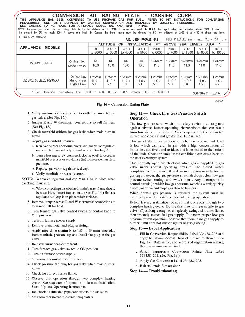
12. Determine main burner orifice size from conversion kitrating plate 336438--201. (Fig. 16.)Furnace gas input rate on rating plate is for installations ataltitudes up to 2000 ft. (609 M).
In the USA, the input rating for altitudes above 2000 ft.(609 M) must be reduced by 2 percent for each 1000 ft.(305 M) above sea level.In Canada, the input rating must be derated by 5 percentfor altitudes of 2000 ft. (609 M) to 4500 ft. (1372 M)above sea level.The Conversion Kit Rating Plate accounts for high altitudede--rate.
13. Install main burner orifices. Do not use Teflon tape.Finger-- tighten orifices at least one full turn to preventcross threading, and then tighten with wrench. There areenough orifices in each kit for the largest furnace. Discardextra orifices.
14. Do not re--install the manifold assembly at this time.
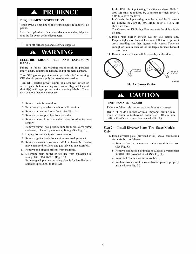
BURNER ORIFICE BURNER
ORIFICE
A96249
Fig. 2 -- Burner Orifice
UNIT DAMAGE HAZARD
Failure to follow this caution may result in unit damage.
DO NOT re--drill burner orifices. Improper drilling mayresult in burrs, out--of--round holes, etc. Obtain neworifices if orifice size must be changed. (Fig. 2.)
CAUTION!
Step 2 — Install Diverter Plate (Two--Stage ModelsOnly
1. Install diverter plate (provided in kit) above combustionair intake box as follows:
a. Remove front two screws on combustion air intake box.(See Fig. 3.)
b. Remove combustion air intake box. Install diverter plate323184--301 provided in kit. (See Fig. 3.)
c. Re--install combustion air intake box .
d. Replace two screws to ensure diverter plate is properlyinstalled. (see Fig. 3.)

4
PROPNAT
COMBUSTIONAIR INTAKE
COMBUSTION AIR INTAKE
BOX SCREWS
COMBUSTION AIR
INTAKE BOX
A09595
Fig. 3 -- Removing Combustion Air Intake Box
PROPNAT
COMBUSTIONAIR INTAKE
DIVERTER PLATEPART NO. 323184-301
PROPNAT
COMBUSTIONAIR INTAKE
A09596
Fig. 4 -- Installing Diverter Plate
Step 3 — Convert Main Gas ValveNOTE: Use propane--gas--resistant pipe dope to prevent gasleaks. DO NOT use Teflon tape.
NOTE: DO NOT reinstall burner enclosure front at this time.
NOTE: The two regulator springs included in the kit areidentical and can be used in either high or low fire regulator orthe main regulator of the single stage furnace.
NOTE: The gas valve used on the 2--stage furnaces MUST haveboth regulator springs replaced and the gas valve MUST bepre--adjusted.
NOTE: The gas valve used on the single stage furnaces MUSThave the regulator spring replaced and the gas valve MUST bepre--adjusted.
Pre--adjustment of the regulator springs are necessary to ensureproper initial main burner ignition and to prevent flashback onignition.
Refer to Step 3a for Two--Stage gas valves or Step 3b for SingleStage gas valves.

5
A05196
Fig. 5 -- Convert Two--Stage Gas Valve
Step 3a — Convert Two Stage Gas Valve (See Fig. 5.)1. Be sure main gas and electrical supplies are turned OFF.
2. Remove both regulator seal caps and set aside.
3. Remove both regulator adjustment screws.
4. Remove both natural gas regulator springs (silver).
5. Install propane gas regulator springs (white).
6. Install regulator adjustment screws.
a. Pre--adjust the High Fire regulator by turning the adjust-ment screw in 13.5 turns.
b. Pre--adjust the Low fire regulator by turning the adjust-ment screw in 9.5 turns.
7. Do not re--install manifold assembly at this time.
Step 3b — Single Stage Gas Valve (See Fig. 6.)1. Be sure main gas and electrical supplies are turned OFF.
ELECTRIC SHOCK, FIRE AND EXPLOSIONHAZARD
Failure to follow this warning could result in personalinjury, death, equipment damage, and/or property damage.
Turn OFF gas supply at manual gas valve before turningOFF electric power supply and starting conversion.
Turn OFF electric power supply at disconnect switch orservice panel before starting conversion. Tag and lockoutshutoff(s) with appropriate device warning labels. Theremay be more than one disconnect.
! WARNING
2. Remove regulator seal cap and set aside.
3. Remove regulator adjustment screws.
4. Remove natural gas regulator spring (silver).
5. Install propane gas regulator spring (white).
6. Install regulator adjustment screw.
a. Pre--adjust regulator by turning the adjustment screw in8.5 turns.
7. Do not re--install manifold assembly at this time.
Step 4 — Install Low Gas Pressure Switch (LGPS)NOTE: The inlet gas pipe must be disconnected from valve sopressure switch can be installed.
NOTE: All parts in this section are included with the conversionkit
NOTE: Use propane gas--resistant pipe dope on all connectionsto prevent gas leaks. DO NOT use Teflon tape.
REGULATOR SEAL CAP
REGULATORADJUSTMENTSCREW
REGULATOR SPRING(PROPANE - WHITE, 8.5 TURNSNATURAL - SILVER, 8.5 TURNS)
GAS PRESSURE REGULATOR ADJUSTMENT
MANIFOLD PRESSURE TAP
INLET PRESSURE TAP
ON/OFF SWITCH
BURNER ENCLOSUREREFERENCE PRESSURETAP
A05193
Fig. 6 -- Convert Single Stage Gas Valve
1. Be sure main gas and electric supplies to furnace are off.
ELECTRIC SHOCK, FIRE AND EXPLOSIONHAZARD
Failure to follow this warning could result in personalinjury, death, equipment damage, and/or property damage.
Turn OFF gas supply at manual gas valve before turningOFF electric power supply and starting conversion.
Turn OFF electric power supply at disconnect switch orservice panel before starting conversion. Tag and lockoutshutoff(s) with appropriate device warning labels. Theremay be more than one disconnect.
! WARNING
2. Remove 1/8--in. (3 mm) pipe plug from inlet pressure tapon gas valve and set aside. (See Fig. 7.) DO NOTDISCARD 1/8--in. (3 mm) PLUG.
3. Apply pipe dope sparingly to the male threads of 1/8--in.(3 mm) iron street elbow.
4. Install the 1/8--in. (3mm) street elbow into the inlet pres-sure tap of the gas valve. Tighten fitting with a small ad-justable wrench. The elbow should be pointing to the leftside of the casing as you face the furnace.
5. Apply pipe dope sparingly to one end of 1/8--in. (3 mm)brass male coupling and install the doped end in the fe-male end of the 1/8--in. (3 mm) street elbow. Tighten fit-ting with a small open--end wrench. (See Fig. 8.)
6. Apply pipe dope sparingly to the other end of 1/8--in. (3mm) brass male coupling
7. Attach the female end of the female x female x male brasstee (provided in kit).Tighten fitting with a small wrench sothe male portion of the tee points out from the furnace(See Fig. 8.)
8. Apply pipe dope sparingly to male end of brass tee. Installpropane low gas pressure switch on tee. After switch hasbeen finger--tightened, use small wrench on base of pres-sure switch for final tightening. When pressure switch istight, switch terminals should point as shown in Fig. 9 rel-ative to gas valve and clear control compartment accessdoor.
NOTE: If gas supply is not available at time of conversion,re--install 1/8--in. (3 mm) pipe plug in open end of brass tee.
9. Connect a manometer fitting to the open end of the tee in-stalled in the inlet pressure tap of the gas valve. (See Fig.9.)

6
A09590
Fig. 7 -- LGPS Fittings
A09591
Fig. 8 -- LGPS Fittings as Installed
A09592
Fig. 9 -- LGPS Installed
IGNIT ER WIRES MUST BE PLACED IN THIS SLOT
A05074
Fig. 10 -- Igniter Wire Placement
Step 5 — Re--install Manifold Assembly1. Reinstall manifold assembly in burner box. Ensure mani-
fold seal grommet is installed properly and burners fit overorifices.
2. Reinsert the igniter wires in the slot in the manifold grom-met, dressing the wires to ensure there is no tension on theigniter itself. (See Fig. 10.)
3. Reconnect hot surface igniter to wiring harness.
4. Reconnect wires to gas valve. Refer to furnace wiringschematic for proper wire location.
5. Reinstall burner box pressure tube to gas valve regulatorfitting.
6. Reinstall burner box pressure tube to intake air box.
7. Apply pipe dope sparingly to end of inlet gas pipe and re-connect gas supply pipe to gas valve using backup wrenchon gas valve to prevent rotation and improper orientation.
Step 6 — Modify Pressure Switch Wiring (Refer tofurnace wiring diagram)NOTE: For Two--Stage furnaces, follow Step 6a, 1 thru 4 below.
NOTE: For Single Stage furnaces, proceed to Step 6b, 1 thru 3below.
Step 6a — Modify Two--Stage Pressure Switch Wiring(Refer to furnace wiring diagram)
1. Disconnect orange wire from low--heat pressure switch(LPS) on inducer housing. Attach wire to C terminal onlow gas pressure switch (LGPS).
2. Using the orange wire (provided in kit) with two insulatedterminals, connect the straight insulated terminal of orangewire to N.O. terminal on low gas pressure switch (LGPS).
3. Connect other end of the wire with the insulated flag ter-minal to the Low Pressure Switch, (LPS) located on in-ducer housing.
4. Route orange wire along wire harness. If possible, securewith wire tie provided in kit.

7
Step 6b — Modify Single Stage Pressure SwitchWiring (Refer to furnace wiring diagram)
1. Disconnect yellow wire from Pressure Switch (PRS) onfurnace inducer housing. Attach wire to C terminal onLow Gas Pressure Switch (LGPS).
2. Using the orange wire (provided in kit) with two insulatedterminals, connect the straight insulated terminal of orangewire to N.O. terminal on Low Gas Pressure Switch(LGPS).
3. Connect other end of the wire with the insulated flag ter-minal to the Pressure Switch, (PRS) located on inducerhousing.
Step 7 — Connect Manometer to Inlet Pressure TapNOTE: This kit is to be used only when inlet gas pressure isbetween 11.5--in. w.c. and 13.6--in. w.c.
1. Connect a manometer to the open end of the LGPS tee fit-ting previously installed on the inlet pressure tap on gasvalve. Remove 1/8--in. (3 mm) pipe plug and installmanometer fitting if necessary. (See Fig. 9 and 11).
2. Turn on furnace power supply.
3. Turn gas supply manual shutoff valve to ON position.
4. Turn furnace gas valve switch to ON position.
5. Check all threaded pipe connections for gas leaks.
FIRE AND EXPLOSION HAZARD
Failure to follow this warning could result in personal injuryand/or death.
NEVER test for gas leaks with an open flame. Use acommercially available soap solution made specifically forthe detection of leaks to check all connections.
! WARNING
Step 8 — Check Inlet Gas PressureNOTE: For Two--Stage furnaces with HK42FZ028 board, turnthe LHT DIP switch on furnace control to ON (See Fig. 12.)Follow Steps 8a, 1 thru 9 below.
NOTE: For Single Stage furnaces, follow steps 8b, 1 thru 8below
Step 8a — Check Inlet Gas Pressure, Two--StageFurnaces:
1. Turn LHT DIP switch on furnace control to ON to lockthe furnace in high fire (See Fig. 12.)
2. Jumper R--W/W1 and R--W2 thermostat connections oncontrol.
3. When main burners ignite, confirm inlet gas pressure isbetween 11.5--in. w.c. and 13.6--in. w.c. (See Fig. 12.)
A09593
Fig. 11 -- Inlet Gas Pressure Check

8
TEST / TWIN
HUM
PLT
SEC-2 SEC-1
COM 24VAC
PL1
W2 Y
DH
UM
G C
OM
W/W
1 Y/Y
2 R
24V
FUSE 3-AMP
EAC-2
EAC-1
L1 BL-1 PR-1
L2
COM
HI HT
COOL
LO HT
SPARE 2 SPARE 1
24V M
TR
TAP
S
BLOWER SPEEDTERMINALS
115-VAC (L2)NEUTRALCONNECTIONS
LED OPERATION& DIAGNOSTIC LIGHT
3-AMP FUSE
24-V THERMOSTATTERMINALS
SET UP SWITCHESLOW HEAT ONLY AND BLOWER OFF-DELAY
TWINNING AND/ORCOMPONENT TESTTERMINAL
ACRDJ - AIR CONDITIONING RELAY DISABLE JUMPER
HUMIDIFIER TERMINAL(24 VAC 0.5 AMPS MAX)
TRANSFORMER24 VAC CONNECTIONS
PL1-LOW VOLTAGEMAIN HARNESS CONNECTOR
PL2 - HOT SURFACEIGNITER/INDUCERMOTOR CONNECTION
115 VACBLOWER POWER (BL1)CONNECTION
115 VAC LINE (L1)CONNECTION
LHTOFFDLY
ON
OF
F
1 2 3
IDR
HSIR IDM
IHI/LOR
PL21
HSI HI LO
1
A08344
Fig. 12 -- Two--Stage Furnace Control
4. Remove jumper across R to W or R--W/W1 and R--W2thermostat connections to terminate call for heat.
5. Turn furnace gas valve switch to OFF position.
6. Turn gas supply manual shutoff valve to OFF position.
7. Turn off furnace power supply.
8. Remove manometer.
9. Apply pipe dope sparingly to end of inlet gas pipe plugand install in unused end of 1/8--in. (3 mm) tee. Use asmall back--up wrench on tee when tightening gas inletpipe plug. (See Fig. 5.)
Step 8b — Check Inlet Gas Pressure, Single StageFurnaces:
1. Jumper across thermostat connections R to W (See Fig.13.)
2. When main burners ignite, confirm inlet gas pressure isbetween 11.5 in. w.c. and 13.6 in. w.c.
3. Remove jumper across R to W thermostat connections toterminate call for heat.
4. Turn gas valve switch to OFF position.
5. Turn gas supply manual shutoff valve to OFF position.
6. Turn off furnace power supply.
7. Remove manometer.
8. Apply pipe dope sparingly to end of inlet gas pipe plugand install in unused end of 1/8” tee. Use a small back--upwrench on tee when tightening gas inlet pipe plug. (SeeFig. 6.)
9
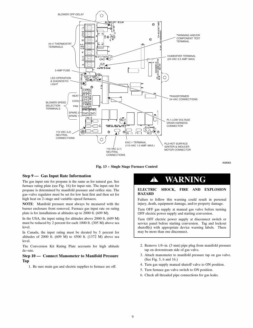
BLOWER OFF-DELAY
24-V THERMOSTATTERMINALS
3-AMP FUSE
LED OPERATION& DIAGNOSTICLIGHT
BLOWER SPEEDSELECTION TERMINALS
HEAT
FAN
COOL
SPARE 2SPARE 1
115-VAC (L2) NEUTRAL CONNECTIONS
115-VAC (L1) NEUTRAL CONNECTIONS
EAC-1 TERMINAL(115-VAC 1.0 AMP. MAX.)
PL2-HOT SURFACE IGNITER & INDUCER MOTOR CONNECTOR
PL1-LOW VOLTAGEDRAIN HARNESS CONNECTOR
TRANSFORMER24-VAC CONNECTIONS
HUMIDIFIER TERMINAL(24-VAC 0.5 AMP. MAX)
TWINNING AND/OR COMPONENT TESTTERMINAL
A08063
Fig. 13 -- Single Stage Furnace Control
Step 9 — Gas Input Rate InformationThe gas input rate for propane is the same as for natural gas. Seefurnace rating plate (see Fig. 16) for input rate. The input rate forpropane is determined by manifold pressure and orifice size. Thegas--valve regulator must be set for low heat first and then set forhigh heat on 2--stage and variable--speed furnaces.
NOTE: Manifold pressure must always be measured with theburner enclosure front removed. Furnace gas input rate on ratingplate is for installations at altitudes up to 2000 ft. (609 M).
In the USA, the input rating for altitudes above 2000 ft. (609 M)must be reduced by 2 percent for each 1000 ft. (305 M) above sealevel.
In Canada, the input rating must be derated by 5 percent foraltitudes of 2000 ft. (609 M) to 4500 ft. (1372 M) above sealevel.
The Conversion Kit Rating Plate accounts for high altitudede--rate.
Step 10 — Connect Manometer to Manifold PressureTap
1. Be sure main gas and electric supplies to furnace are off.
ELECTRIC SHOCK, FIRE AND EXPLOSIONHAZARD
Failure to follow this warning could result in personalinjury, death, equipment damage, and/or property damage.
Turn OFF gas supply at manual gas valve before turningOFF electric power supply and starting conversion.
Turn OFF electric power supply at disconnect switch orservice panel before starting conversion. Tag and lockoutshutoff(s) with appropriate device warning labels. Theremay be more than one disconnect.
! WARNING
2. Remove 1/8--in. (3 mm) pipe plug from manifold pressuretap on downstream side of gas valve.
3. Attach manometer to manifold pressure tap on gas valve.(See Fig. 5, 6 and 16.)
4. Turn gas supply manual shutoff valve to ON position.
5. Turn furnace gas valve switch to ON position.
6. Check all threaded pipe connections for gas leaks.

10
FIRE AND EXPLOSION HAZARD
Failure to follow this warning could result in personal injuryand/or death.
NEVER test for gas leaks with an open flame. Use acommercially available soap solution made specifically forthe detection of leaks to check all connections.
! WARNING
7. Turn on furnace power supply.
BURNER FLAME
BURNER
MANIFOLD
A05219
Fig. 14 -- Burner Flame
765432101234567
BURNER ENCLOSURE(REMOVE COVER WHEN CHECKING PRESSURE)
GAS VALVE
PRESSURESWITCH(ES)
(LOCATION WILL VARYDEPENDING ON MODEL)
MANOMETER
A01070
Fig. 15 -- Checking Manifold Pressure
Step 11 — Set Gas Input Rate/Adjust ManifoldPressureFor Two--Stage furnaces, follow Step 11a, 1 thru 18 below.
For Single Stage furnaces, follow Step 11b, 1 thru 17 below.
Step 11a — Set Gas Input Rate/Adjust ManifoldPressure-- Two Stage FurnacesNOTE: Manifold pressure MUST always be measured withburner box cover removed.
1. Verify manometer is connected to manifold pressure tapon gas valve. (See Fig. 15.)
2. Jumper R and W/W1 thermostat connections to call forheat.
3. Check manifold orifices for gas leaks when main burnersignite.
FIRE AND EXPLOSION HAZARD
Failure to follow this warning could result in personal injuryand/or death.
NEVER test for gas leaks with an open flame. Use acommercially available soap solution made specifically forthe detection of leaks to check all connections.
! WARNING
4. Adjust gas manifold pressure. (See Fig. 5.)
a. Remove caps that conceal adjustment screws for gasvalve regulators.
b. Adjust low--heat input rate manifold pressure for propanegas.
c. Turn low--heat regulator adjusting screw counterclock-wise (out) to decrease input rate or clockwise (in) to in-crease input rate.
d. Main burner flame should be clear blue, almost transpar-ent.
5. Jumper R, W/W1 and W2 on control center thermostatconnections. This keeps furnace locked in high--heat oper-ation.
a. Adjust high--heat input rate manifold pressure for pro-pane gas.
b. Turn high--heat regulator adjusting screw counterclock-wise (out) to decrease input rate or clockwise (in) to in-crease input rate.
c. Remove jumper across R, W1, and W2 after high--heatadjustment to terminate call for heat.
d. Replacecaps that conceal gas--valve regulator adjustmentscrews.
e. Main burner flame should be clear blue, almost transpar-ent. (See Fig. 14.)
6. Turn setup switch LHT to OFF position.
7. Turn furnace gas--valve switch to OFF position.
8. Turn off furnace power supply.
9. Remove manometer and adapter fitting for manometer.
10. Apply pipe dope sparingly to 1/8--in. (3 mm) pipe plugfrom manifold pressure tap and install the plug in the gasvalve.
11. Reinstall burner enclosure front.
12. Turn furnace gas--valve switch to ON position.
13. Turn on furnace power supply.
14. Set room thermostat to call for heat.
15. Check pressure tap plug for gas leaks when main burnersignite.
16. Check for correct burner flame.
17. Observe unit operation through two complete heatingcycles. See sequence of operation in furnace Installation,Start--Up, and Operating Instructions.
18. Set room thermostat to desired temperature.
Step 11b — Set Gas Input Rate/Adjust ManifoldPressure-- Single Stage FurnacesNOTE: Manifold pressure MUST always be measured withburner box cover removed.
11
A09605
Fig. 16 -- Conversion Rating Plate
1. Verify manometer is connected to outlet pressure tap ongas valve. (See Fig. 15.)
2. Jumper R and W thermostat connections to call for heat.(See Fig. 13.)
3. Check manifold orifices for gas leaks when main burnersignite.
4. Adjust gas manifold pressure.
a. Remove burner enclosure cover and gas valve regulatorseal cap that conceal adjustment screw. (See Fig. 4.)
b. Turn adjusting screw counterclockwise (out) to decreasemanifold pressure or clockwise (in) to increase manifoldpressure.
c. Replace gas valve regulator seal cap.
d. Verify manifold pressure is correct.
NOTE: Gas valve regulator seal cap MUST be in place whenchecking input rate.
e. When correct input isobtained, main burner flameshouldbe clear blue, almost transparent. (See Fig. 14.) Be sureregulator seal cap is in place when finished.
5. Remove jumper across R and W thermostat connections toterminate call for heat.
6. Turn furnace gas valve control switch or control knob toOFF position.
7. Turn off furnace power supply.
8. Remove manometer and adapter fitting.
9. Apply pipe dope sparingly to 1/8--in. (3 mm) pipe plugfrom manifold pressure tap and install the plug in the gasvalve.
10. Reinstall burner enclosure front.
11. Turn furnace gas--valve switch to ON position.
12. Turn on furnace power supply.
13. Set room thermostat to call for heat.
14. Check pressure tap plug for gas leaks when main burnersignite.
15. Check for correct burner flame.
16. Observe unit operation through two complete heatingcycles. See sequence of operation in furnace Installation,Start-- Up, and Operating Instructions.
17. Re--check all threaded pipe connections for gas leaks.
18. Set room thermostat to desired temperature.
Step 12 — Check Low Gas Pressure SwitchOperationThe low gas pressure switch is a safety device used to guardagainst adverse burner operating characteristics that can resultfrom low gas supply pressure. Switch opens at not less than 6.5in. w.c. and closes at not greater than 10.2 in. w.c.
This switch also prevents operation when the propane tank levelis low which can result in gas with a high concentration ofimpurities, additives, and residues that have settled to the bottomof the tank. Operation under these conditions can cause harm tothe heat exchanger system.
This normally open switch closes when gas is supplied to gasvalve under normal operating pressure. The closed switchcompletes control circuit. Should an interruption or reduction ingas supply occur, the gas pressure at switch drops below low gaspressure switch setting, and switch opens. Any interruption incontrol circuit (in which low gas pressure switch is wired) quicklycloses gas valve and stops gas flow to burners.
When normal gas pressure is restored, the system must beelectrically reset to reestablish normal heating operation.
Before leaving installation, observe unit operation through twocomplete heating cycles. During this time, turn gas supply to gasvalve off just long enough to completely extinguish burner flame,then instantly restore full gas supply. To ensure proper low gaspressure switch operation, observe that there is no gas supply toburners until after hot surface igniter begins glowing.
Step 13 — Label Application1. Fill in Conversion Responsibility Label 336438--205 and
apply to Blower Access Door of furnace as shown. (SeeFig. 17.) Date, name, and address of organization makingthis conversion are required.
2. Attach appropriate Conversion Rating Plate Label336438--201, (See Fig. 16.)
3. Apply Gas Conversion Label 336438--203.
4. Reinstall main furnace door.
Step 14 — Troubleshooting

12
FURNACE CONVERSIONRATING PLATE
FURNACERATING
PLATE
RESPONSIBILITYLABEL
GAS CONTROLCONVERSION
LABEL
BURNERENCLOSURE
GAS VALVE
CONTROL
A01025
Fig. 17 -- Label Application
Copyright 2009 CAC / BDP S 7310 W. Morris St. S Indianapolis, IN 46231
Manufacturer reserves the right to change, at any time, specifications and designs without notice and without obligations.
Catalog No: IIK---KGANP4901---01Replaces: New
Printed in U.S.A. Edition Date: 10/09