
ControlLogix 5580 Controllers -...
152
ControlLogix 5580 Controllers Catalog Numbers 1756-L83E, 1756-L85E User Manual
Transcript of ControlLogix 5580 Controllers -...

ControlLogix 5580 ControllersCatalog Numbers 1756-L83E, 1756-L85E
User Manual
Important User Information
Read this document and the documents listed in the additional resources section about installation, configuration, and operation of this equipment before you install, configure, operate, or maintain this product. Users are required to familiarize themselves with installation and wiring instructions in addition to requirements of all applicable codes, laws, and standards.
Activities including installation, adjustments, putting into service, use, assembly, disassembly, and maintenance are required to be carried out by suitably trained personnel in accordance with applicable code of practice.
If this equipment is used in a manner not specified by the manufacturer, the protection provided by the equipment may be impaired.
In no event will Rockwell Automation, Inc. be responsible or liable for indirect or consequential damages resulting from the use or application of this equipment.
The examples and diagrams in this manual are included solely for illustrative purposes. Because of the many variables and requirements associated with any particular installation, Rockwell Automation, Inc. cannot assume responsibility or liability for actual use based on the examples and diagrams.
No patent liability is assumed by Rockwell Automation, Inc. with respect to use of information, circuits, equipment, or software described in this manual.
Reproduction of the contents of this manual, in whole or in part, without written permission of Rockwell Automation, Inc., is prohibited.
Throughout this manual, when necessary, we use notes to make you aware of safety considerations.
Labels may also be on or inside the equipment to provide specific precautions.
Allen-Bradley, ArmorBlock, ArmorPOINT, Block I/O, Compact I/O, CompactLogix, ControlFLASH, ControlLogix, ControlLogix-XT, Data Highway Plus, DH+, DriveGuard, FactoryTalk, FLEX, Flex I/O, Integrated Architecture, Kinetix, Logix5000, Logix Designer, PanelView, PLC-5, POINT I/O, PowerFlex, QuickView, RediSTATION, Rockwell Automation, Rockwell Software, RSFieldbus, RSLinx, RSNetWorx, RSView, Series 9000, SLC, SLC 500, Stratix, Stratix 5400, Stratix 5700, Studio 5000, Studio 5000 Automation & Engineering Design Environment, and Studio 5000 Logix Designer are trademarks of Rockwell Automation.
Trademarks not belonging to Rockwell Automation are property of their respective companies.
WARNING: Identifies information about practices or circumstances that can cause an explosion in a hazardous environment, which may lead to personal injury or death, property damage, or economic loss.
ATTENTION: Identifies information about practices or circumstances that can lead to personal injury or death, property damage, or economic loss. Attentions help you identify a hazard, avoid a hazard, and recognize the consequence.
IMPORTANT Identifies information that is critical for successful application and understanding of the product.
SHOCK HAZARD: Labels may be on or inside the equipment, for example, a drive or motor, to alert people that dangerous voltage may be present.
BURN HAZARD: Labels may be on or inside the equipment, for example, a drive or motor, to alert people that surfaces may reach dangerous temperatures.
ARC FLASH HAZARD: Labels may be on or inside the equipment, for example, a motor control center, to alert people to potential Arc Flash. Arc Flash will cause severe injury or death. Wear proper Personal Protective Equipment (PPE). Follow ALL Regulatory requirements for safe work practices and for Personal Protective Equipment (PPE).
Summary of Changes
This manual contains new and updated information. Changes throughout this revision are marked by change bars, as shown to the right of this paragraph.
New and Updated Information
This table contains the changes made to this revision.
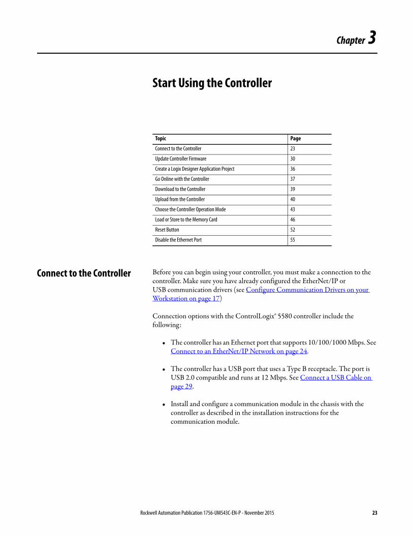
Topic Page
Updated the diagram for multiple controllers in one chassis. 12
Updated title for Figure 8. 58
Updated title for Figure 18. 85
Rockwell Automation Publication 1756-UM543C-EN-P - November 2015 3

Summary of Changes
Notes:
4 Rockwell Automation Publication 1756-UM543C-EN-P - November 2015
Table of Contents
Preface ControlLogix 5580 Controllers Overview. . . . . . . . . . . . . . . . . . . . . . . . . . . . 9Before You Begin . . . . . . . . . . . . . . . . . . . . . . . . . . . . . . . . . . . . . . . . . . . . . . . . . . 9
Required Software . . . . . . . . . . . . . . . . . . . . . . . . . . . . . . . . . . . . . . . . . . . . . . 9Additional Resources . . . . . . . . . . . . . . . . . . . . . . . . . . . . . . . . . . . . . . . . . . . . . . . 9
Chapter 1ControlLogix System and Controllers Minimum Requirements. . . . . . . . . . . . . . . . . . . . . . . . . . . . . . . . . . . . . . . . . . 11
ControlLogix System . . . . . . . . . . . . . . . . . . . . . . . . . . . . . . . . . . . . . . . . . . . . . 11Configuration Options . . . . . . . . . . . . . . . . . . . . . . . . . . . . . . . . . . . . . . . 12
Design a ControlLogix System . . . . . . . . . . . . . . . . . . . . . . . . . . . . . . . . . . . . 14ControlLogix 5580 Controller Features. . . . . . . . . . . . . . . . . . . . . . . . . . . . 14
System, Communication, and Programming Features . . . . . . . . . . . 14Direct connection to an EtherNet/IP Network . . . . . . . . . . . . . . . . . 15Secure Digital (SD) Card . . . . . . . . . . . . . . . . . . . . . . . . . . . . . . . . . . . . . 15
Chapter 2Configure Communication Drivers on your Workstation
Configure the Ethernet Communication Driver in RSLinx Classic Software . . . . . . . . . . . . . . . . . . . . . . . . . . . . . . . . . . . . . . . . . . 18Configure the USB Communication Driver in RSLinx Classic Software . . . . . . . . . . . . . . . . . . . . . . . . . . . . . . . . . . . . . . . . . . 20
Chapter 3Start Using the Controller Connect to the Controller . . . . . . . . . . . . . . . . . . . . . . . . . . . . . . . . . . . . . . . . 23
Connect to an EtherNet/IP Network . . . . . . . . . . . . . . . . . . . . . . . . . . 24Connect a USB Cable . . . . . . . . . . . . . . . . . . . . . . . . . . . . . . . . . . . . . . . . 29
Update Controller Firmware. . . . . . . . . . . . . . . . . . . . . . . . . . . . . . . . . . . . . . 30Determine Required Controller Firmware. . . . . . . . . . . . . . . . . . . . . . 30Obtain Controller Firmware . . . . . . . . . . . . . . . . . . . . . . . . . . . . . . . . . . 30Use ControlFLASH Software to Update Firmware . . . . . . . . . . . . . 31Use AutoFlash to Update Firmware. . . . . . . . . . . . . . . . . . . . . . . . . . . . 34
Create a Logix Designer Application Project. . . . . . . . . . . . . . . . . . . . . . . . 36Go Online with the Controller . . . . . . . . . . . . . . . . . . . . . . . . . . . . . . . . . . . . 37Download to the Controller . . . . . . . . . . . . . . . . . . . . . . . . . . . . . . . . . . . . . . 39
Use the Who Active Dialog Box to Download . . . . . . . . . . . . . . . . . . 39Use the Controller Status Menu to Download . . . . . . . . . . . . . . . . . . 40
Upload from the Controller. . . . . . . . . . . . . . . . . . . . . . . . . . . . . . . . . . . . . . . 40Use the Who Active Dialog Box to Upload . . . . . . . . . . . . . . . . . . . . . 40Use the Controller Status Menu to Upload . . . . . . . . . . . . . . . . . . . . . 41
Choose the Controller Operation Mode . . . . . . . . . . . . . . . . . . . . . . . . . . . 43Use the Mode Switch to Change the Operation Mode. . . . . . . . . . . 43Use Logix Designer to Change the Operation Mode. . . . . . . . . . . . . 45
Load or Store to the Memory Card . . . . . . . . . . . . . . . . . . . . . . . . . . . . . . . . 46Store to the Memory Card . . . . . . . . . . . . . . . . . . . . . . . . . . . . . . . . . . . . 46Load from the Memory Card . . . . . . . . . . . . . . . . . . . . . . . . . . . . . . . . . . 49Other Memory Card Tasks. . . . . . . . . . . . . . . . . . . . . . . . . . . . . . . . . . . . 51
Rockwell Automation Publication 1756-UM543C-EN-P - November 2015 5
Table of Contents
Reset Button . . . . . . . . . . . . . . . . . . . . . . . . . . . . . . . . . . . . . . . . . . . . . . . . . . . . . 52Stage 1 Reset . . . . . . . . . . . . . . . . . . . . . . . . . . . . . . . . . . . . . . . . . . . . . . . . . 53Stage 2 Reset . . . . . . . . . . . . . . . . . . . . . . . . . . . . . . . . . . . . . . . . . . . . . . . . . 54
Disable the Ethernet Port . . . . . . . . . . . . . . . . . . . . . . . . . . . . . . . . . . . . . . . . . 55
Chapter 4Communication Networks Networks Available . . . . . . . . . . . . . . . . . . . . . . . . . . . . . . . . . . . . . . . . . . . . . . . 57
EtherNet/IP Network Communication . . . . . . . . . . . . . . . . . . . . . . . . . . . . 58ControlLogix EtherNet/IP Network Features . . . . . . . . . . . . . . . . . . 59ControlLogix EtherNet/IP Communication Modules . . . . . . . . . . . 59Software for EtherNet/IP Networks. . . . . . . . . . . . . . . . . . . . . . . . . . . . 60Double Data Rate (DDR) Backplane Communication. . . . . . . . . . . 61
ControlNet Network Communication. . . . . . . . . . . . . . . . . . . . . . . . . . . . . 61ControlLogix ControlNet Module Features . . . . . . . . . . . . . . . . . . . . 62ControlLogix ControlNet Modules . . . . . . . . . . . . . . . . . . . . . . . . . . . . 63Software for ControlNet Networks . . . . . . . . . . . . . . . . . . . . . . . . . . . . 63
DeviceNet Network Communication . . . . . . . . . . . . . . . . . . . . . . . . . . . . . . 64ControlLogix DeviceNet Module Features. . . . . . . . . . . . . . . . . . . . . . 64ControlLogix DeviceNet Bridge Module and Linking Devices. . . . 65Software for DeviceNet Networks. . . . . . . . . . . . . . . . . . . . . . . . . . . . . . 65Connections Over DeviceNet Networks. . . . . . . . . . . . . . . . . . . . . . . . 65ControlLogix DeviceNet Module Memory . . . . . . . . . . . . . . . . . . . . . 65
Data Highway Plus (DH+) Network Communication . . . . . . . . . . . . . . 66Communicate Over a DH+ Network . . . . . . . . . . . . . . . . . . . . . . . . . . 67
Universal Remote I/O (RIO) Communication . . . . . . . . . . . . . . . . . . . . . 68Communicate Over a Universal Remote I/O Network . . . . . . . . . . 69
Foundation Fieldbus Communication . . . . . . . . . . . . . . . . . . . . . . . . . . . . . 70HART Communication . . . . . . . . . . . . . . . . . . . . . . . . . . . . . . . . . . . . . . . . . . 71
Chapter 5Manage Controller Communication Connection Overview . . . . . . . . . . . . . . . . . . . . . . . . . . . . . . . . . . . . . . . . . . . . 73
Nodes on an EtherNet/IP Network. . . . . . . . . . . . . . . . . . . . . . . . . . . . . . . . 74Devices Included in the Node Count . . . . . . . . . . . . . . . . . . . . . . . . . . . 74Devices Excluded from the Node Count . . . . . . . . . . . . . . . . . . . . . . . . 74
Controller Communication Interaction with Control Data. . . . . . . . . . 75Produce and Consume (Interlock) Data . . . . . . . . . . . . . . . . . . . . . . . . . . . . 77
Requested Packet Interval (RPI) of Multicast Tags . . . . . . . . . . . . . . 78Send and Receive Messages . . . . . . . . . . . . . . . . . . . . . . . . . . . . . . . . . . . . . . . . 78
Determine Whether to Cache Message Connections . . . . . . . . . . . . 79Socket Interface . . . . . . . . . . . . . . . . . . . . . . . . . . . . . . . . . . . . . . . . . . . . . . . . . . 80
Chapter 6I/O Modules Selecting ControlLogix
I/O Modules . . . . . . . . . . . . . . . . . . . . . . . . . . . . . . . . . . . . . . . . . . . . . . . . . . . . . 81Electronic Keying. . . . . . . . . . . . . . . . . . . . . . . . . . . . . . . . . . . . . . . . . . . . . 82
Local I/O Modules . . . . . . . . . . . . . . . . . . . . . . . . . . . . . . . . . . . . . . . . . . . . . . . 83Add Local I/O to the I/O Configuration . . . . . . . . . . . . . . . . . . . . . . . 83
6 Rockwell Automation Publication 1756-UM543C-EN-P - November 2015
Table of Contents
Remote I/O Modules. . . . . . . . . . . . . . . . . . . . . . . . . . . . . . . . . . . . . . . . . . . . . 85Add Remote I/O to the Ethernet Port on the Controller . . . . . . . . 86Add Remote I/0 to a Local Communication Module . . . . . . . . . . . . 88
Add to the I/O Configuration While Online . . . . . . . . . . . . . . . . . . . . . . . 92Modules and Devices that Can be Added While Online . . . . . . . . . 92
Determine When Data is Updated . . . . . . . . . . . . . . . . . . . . . . . . . . . . . . . . 93Input Data Update Flowchart . . . . . . . . . . . . . . . . . . . . . . . . . . . . . . . . . 93Output Data Update Flowchart . . . . . . . . . . . . . . . . . . . . . . . . . . . . . . . 94
Chapter 7Develop Applications Elements of a Control Application . . . . . . . . . . . . . . . . . . . . . . . . . . . . . . . . 95
Tasks. . . . . . . . . . . . . . . . . . . . . . . . . . . . . . . . . . . . . . . . . . . . . . . . . . . . . . . . . . . . 96Task Priority . . . . . . . . . . . . . . . . . . . . . . . . . . . . . . . . . . . . . . . . . . . . . . . . . 99
Programs . . . . . . . . . . . . . . . . . . . . . . . . . . . . . . . . . . . . . . . . . . . . . . . . . . . . . . . . 99Scheduled and Unscheduled Programs . . . . . . . . . . . . . . . . . . . . . . . . 101
Routines . . . . . . . . . . . . . . . . . . . . . . . . . . . . . . . . . . . . . . . . . . . . . . . . . . . . . . . 102Parameters and Local Tags . . . . . . . . . . . . . . . . . . . . . . . . . . . . . . . . . . . . . . . 103Programming Languages . . . . . . . . . . . . . . . . . . . . . . . . . . . . . . . . . . . . . . . . . 104Add-On Instructions . . . . . . . . . . . . . . . . . . . . . . . . . . . . . . . . . . . . . . . . . . . . 105Extended Properties . . . . . . . . . . . . . . . . . . . . . . . . . . . . . . . . . . . . . . . . . . . . . 106Access the Module Object from an Add-On Instruction. . . . . . . . . . . . 107
Create the Add-On Instruction. . . . . . . . . . . . . . . . . . . . . . . . . . . . . . . 107Monitoring Controller Status . . . . . . . . . . . . . . . . . . . . . . . . . . . . . . . . . . . . 108Monitoring I/O Connections . . . . . . . . . . . . . . . . . . . . . . . . . . . . . . . . . . . . 108
Determine If I/O Communication Has Timed Out . . . . . . . . . . . . 109Determine if I/O Communication to a Specific I/O Module has Timed Out . . . . . . . . . . . . . . . . . . . . . . . . . . . . . . . . . . . . . . . . . . . . . . 110Automatic Handling of I/O Module Connection Faults . . . . . . . . 110Sample Controller Projects . . . . . . . . . . . . . . . . . . . . . . . . . . . . . . . . . . . 111
Chapter 8Develop Motion Applications Motion Overview . . . . . . . . . . . . . . . . . . . . . . . . . . . . . . . . . . . . . . . . . . . . . . . 113
Motion Applications . . . . . . . . . . . . . . . . . . . . . . . . . . . . . . . . . . . . . . . . . . . . 114Program Motion Control . . . . . . . . . . . . . . . . . . . . . . . . . . . . . . . . . . . . . . . . 114
Example . . . . . . . . . . . . . . . . . . . . . . . . . . . . . . . . . . . . . . . . . . . . . . . . . . . . 115Obtain Axis Information . . . . . . . . . . . . . . . . . . . . . . . . . . . . . . . . . . . . . . . . 116
Chapter 9Troubleshoot the Controller Controller Diagnostics with Logix Designer . . . . . . . . . . . . . . . . . . . . . . . 117
Warning Symbol and Controller State Indicators . . . . . . . . . . . . . . 117I/O Module Properties Tab . . . . . . . . . . . . . . . . . . . . . . . . . . . . . . . . . . 118Notification in the Tag Editor . . . . . . . . . . . . . . . . . . . . . . . . . . . . . . . . 119Enable Major Fault on Controller . . . . . . . . . . . . . . . . . . . . . . . . . . . . 119Port Diagnostics. . . . . . . . . . . . . . . . . . . . . . . . . . . . . . . . . . . . . . . . . . . . . 120Advanced Time Sync . . . . . . . . . . . . . . . . . . . . . . . . . . . . . . . . . . . . . . . . 122
Rockwell Automation Publication 1756-UM543C-EN-P - November 2015 7

Table of Contents
Controller Diagnostics with RSLinx Software . . . . . . . . . . . . . . . . . . . . . 124General Tab. . . . . . . . . . . . . . . . . . . . . . . . . . . . . . . . . . . . . . . . . . . . . . . . . 125Port Diagnostics Tab. . . . . . . . . . . . . . . . . . . . . . . . . . . . . . . . . . . . . . . . . 125Connection Manager Tab . . . . . . . . . . . . . . . . . . . . . . . . . . . . . . . . . . . . 127USB Tab. . . . . . . . . . . . . . . . . . . . . . . . . . . . . . . . . . . . . . . . . . . . . . . . . . . . 128
Controller Web Pages . . . . . . . . . . . . . . . . . . . . . . . . . . . . . . . . . . . . . . . . . . . 129Tasks Webpage . . . . . . . . . . . . . . . . . . . . . . . . . . . . . . . . . . . . . . . . . . . . . . 130Browse Chassis Webpage . . . . . . . . . . . . . . . . . . . . . . . . . . . . . . . . . . . . . 131
Appendix AStatus Indicators 4-Character Status Display . . . . . . . . . . . . . . . . . . . . . . . . . . . . . . . . . . . . . . . 134
General Status Messages . . . . . . . . . . . . . . . . . . . . . . . . . . . . . . . . . . . . . . 134Fault Messages. . . . . . . . . . . . . . . . . . . . . . . . . . . . . . . . . . . . . . . . . . . . . . . 136Major Fault Messages . . . . . . . . . . . . . . . . . . . . . . . . . . . . . . . . . . . . . . . . 137I/O Fault Codes . . . . . . . . . . . . . . . . . . . . . . . . . . . . . . . . . . . . . . . . . . . . . 139
Controller Status Indicators . . . . . . . . . . . . . . . . . . . . . . . . . . . . . . . . . . . . . . 142RUN Indicator . . . . . . . . . . . . . . . . . . . . . . . . . . . . . . . . . . . . . . . . . . . . . . 142FORCE Indicator . . . . . . . . . . . . . . . . . . . . . . . . . . . . . . . . . . . . . . . . . . . 142SD Indicator . . . . . . . . . . . . . . . . . . . . . . . . . . . . . . . . . . . . . . . . . . . . . . . . 142OK Indicator. . . . . . . . . . . . . . . . . . . . . . . . . . . . . . . . . . . . . . . . . . . . . . . . 143
EtherNet/IP Indicators . . . . . . . . . . . . . . . . . . . . . . . . . . . . . . . . . . . . . . . . . . 143Thermal Monitoring and Thermal Fault Behavior . . . . . . . . . . . . . . . . . 144
Index . . . . . . . . . . . . . . . . . . . . . . . . . . . . . . . . . . . . . . . . . . . . . . . . . . . . . . . . . . . . . . . . 145
8 Rockwell Automation Publication 1756-UM543C-EN-P - November 2015
Preface
ControlLogix 5580 Controllers Overview
This manual explains how to use standard ControlLogix® 5580 controllers.
Before You Begin Before you begin using your ControlLogix controller, verify that you have the applications that are required to configure and program the controller.
Required Software
Use Table 2 to identify the minimum software versions that are required to use your ControlLogix controller.
Additional Resources These documents contain additional information concerning related products from Rockwell Automation.
Table 1 - ControlLogix Catalog Numbers
Cat. No.
1756-L83E, 1756-L85E
Table 2 - Required Software for Controller Use
Cat. No. Studio 5000 Logix Designer® RSLinx® Classic
1756-L83E Version 28.00.00 or later Version 3.80 or later
1756-L85E Version 28.00.00 or later Version 3.80 or later
Resource Description
ControlLogix 5580 Controllers Product Information, publication 1756-PC405
Provides installation instructions for ControlLogix 5580 controllers.
1756 ControlLogix Controllers Technical Data, publication 1756-TD001
Provides specifications for ControlLogix controllers.
1756 ControlLogix I/O Specifications Technical Data, publication 1756-TD002
Provides specifications for ControlLogix I/O modules.
EtherNet/IP Communication Modules in 5000 Series Systems User Manual, publication ENET-UM004
How to install and configure the 5069 EtherNet/IP adapter.
5069 I/O Modules Specifications Technical Data, publication 5069-TD001
Provides 5069-AEN2TR EtherNet/IP Adapter and 5069 Compact I/O™ specifications.
ControlLogix Analog I/O Modules User Manual, publication 1756-UM009
Provides information about analog I/O module configuration properties.
ControlLogix Chassis and Power Supply Installation Instructions, publication 1756-IN005
Describes how to install and troubleshoot standard and ControlLogix-XT™ versions of the 1756 chassis and power supplies, including redundant power supplies.
ControlLogix Peer I/O Control Application Technique, publication 1756-AT016
Describes typical peer control applications and provides details about how to configure I/O modules for peer control operation.
ControlLogix System Selection Guide, publication 1756-SG001
Provides information about designing and selecting components for your ControlLogix system.
Rockwell Automation Publication 1756-UM543C-EN-P - November 2015 9
Preface
You can view or download publications athttp://www.rockwellautomation.com/literature/.
To order paper copies of technical documentation, contact your local Allen-Bradley distributor or Rockwell Automation sales representative.
Ethernet Design Considerations Reference Manual, publication ENET-RM002
Provides additional information about network design for your system.
ControlNet Network Configuration User Manual, publication CNET-UM001
Provides information about ControlNet networks.
DeviceNet Media Design Installation Guide, publication DNET-UM072
Provides information about DeviceNet networks.
FOUNDATION Fieldbus Design Considerations Reference Manual, PROCES-RM005
This document provides design choices and best practices for implementing a FOUNDATION Fieldbus network with the 1788-EN2FFR or 1788-CN2FFR linking devices.
Integrated Architecture and CIP Sync Configuration Application Technique, publication IA-AT003
Describes how to configure CIP Sync with Integrated Architecture® products and applications.
Integrated Motion on the EtherNet/IP Network Configuration and Startup User Manual, publication MOTION-UM003
Details how to design your ControlLogix system for Integrated Motion on the EtherNet/IP network applications.
Logix5000 Controllers Design Considerations Reference Manual, publication 1756-RM094
Provides information to help design and plan Logix systems.
Logix5000 Controllers Add-On Instructions Programming Manual, publication 1756-PM010
Provides more information about using add-on instructions.
Logix5000 Controllers I/O and Tag Data Programming Manual, publication 1756-PM004
Describes how to create and configure program tags for optimal task and program execution.
Logix5000 Controllers Major, Minor and I/O Faults Programming Manual, publication 1756-PM014
Provides more information for I/O faults.
Logix5000 Controllers Messages Programming Manual, publication 1756-PM012
Provides information for controller messages.
Logix5000 Controllers Motion Instructions Reference Manual, publication MOTION-RM002
Provides programmers with details about the motion instructions that are available for a Logix5000™ controller.
Logix5000 Controllers Nonvolatile Memory Card Programming Manual, publication 1756-PM017
Provides information about how to change the project that is available to load from nonvolatile memory,
Logix5000 Controllers Produced and Consumed Tags Programming Manual, publication 1756-PM011
Provides more information for produced and consumed tags.
Motion Coordinate System User Manual, publication MOTION-UM002
Details how to create and configure a coordinated motion application system.
Runtime/On-line Addition of ControlLogix (1756) I/O over ControlNet and EtherNet/IP White Paper, publication LOGIX-WP006
Provides information for adding to the I/O Configuration while online.
Using Logix5000 Controllers as Masters or Slaves on Modbus Application Solution, publication CIG-AP129
For more information about using Modbus sample programs.
Guidance for Selecting Cables for EtherNet/IP Networks, publication ENET-WP007-EN-P
Provides information on how to select cabling based on the application, environmental conditions, and mechanical requirements.
Industrial Automation Wiring and Grounding Guidelines Application Data, publication 1770-4.1
Provides general guidelines for installing a Rockwell Automation industrial system.
Product Certifications website, http://www.rockwellautomation.com/rockwellautomation/certification/overview.page
Provides declarations of conformity, certificates, and other certification details.
Resource Description
10 Rockwell Automation Publication 1756-UM543C-EN-P - November 2015
Chapter 1
ControlLogix System and Controllers
This chapter describes features and functions that are associated with the ControlLogix® 5580 controllers.
Minimum Requirements The controllers have these minimum requirements.
Minimum operating requirements: • ControlLogix Chassis, Series C (a Series B chassis functions within a
derated temperature range)• ControlLogix Chassis Power Supply
Additional minimum requirements to configure the controller for operation:
• Studio 5000 Logix Designer® Version 28 or later• RSLinx® Classic version 3.80• ControlFlash version 13.00
ControlLogix System The ControlLogix system is chassis-based, which provides options for configuring a variety of communications and I/O capabilities. The controller supports multiple programming languages that enable sequential, process, motion, and drive control.
Topic Page
Minimum Requirements 11
ControlLogix System 11
Design a ControlLogix System 14
ControlLogix 5580 Controller Features 14
Rockwell Automation Publication 1756-UM543C-EN-P - November 2015 11

Chapter 1 ControlLogix System and Controllers
Configuration Options
This section describes some of the many system configuration options that are available with ControlLogix controllers.
Standalone Controller and I/O
One of the simplest ControlLogix configurations is a standalone controller with I/O assembled in one chassis.
Figure 1 - Standalone Controller and I/O
Multiple Controllers in One Chassis
For some applications, you can use multiple controllers in one ControlLogix chassis. The following example shows a ControlLogix 5580 controller connecting directly to the EtherNet/IP Network, and a ControlLogix 5570 controller connecting to the network through a 1756-EN2TR module.
Figure 2 - Multiple Controllers in One Chassis
OKFORCE SDRUN
Logix5585
LINK
NET
TM
SAFETY ON
0 0 0 0
DC INPUT AC OUTPUTDC INPUT
RUN PROGREM
Logix5585E
NET
LINK
SAFETY ON
RUN PROGREM
Logix5585E
NET
LINK
SAFETY ON
EIP
Mod
EIP
Net
Setu
p
GPS
Tim
eCD
3
1
4
2
Out
1
2
Spee
d
Dup
lex
PRP
DLR Po
E
Alarms PSU
1 2 3 4 5 6 7 8 9 10 11 12 25 26
13
1 4 5 8 9 1210/100/1000 PoE+
100/1000 SFP 100/1000 SFP+
GPS ANT. DIG.TimeCode ANA.TimeCode
Console Alarm
TOD
16 17 20 21 24 25
OUT
IN
OUT
IN
28
272421 22 232017 18 191613 14 15 28
ExpressSetup
Disp.Mode
CAUTIONHOT surfaces can cause severe burns
54 6
8
23
9
1
7
0
STS
ENET
LINK
AUTOAt ReferenceF
00
6 0 . 00 Hz
ESC
PowerFlex 755480V 4.2A20G . . . B4P2
REF TEXTPAR#
755
ModNet5700
ModNet5700
ModNet5700
5069-IB16 5069-FPD 5069-ARM
COMPACT I/O
2
1
NETLNK2 OKLNK1
0 20 1734-AENTR
ModuleStatus
NetworkActivity
NetworkStatus
Point BusStatus
SystemPower
FieldPower
POINT I O
Link 1 Activity/Status
Link 2 Activity/Status
IP A
DD
RE
SS
PanelView™ Plus 7
ControlLogix 5580 Controller
Stratix 5700™
5069-AEN2TR 5069 Compact I/O™
Kinetix® 5700
PowerFlex® 755
Stratix 5410™1 Gbps
100 Mbps
1 Gbps 100 Mbps
100 Mbps
1 Gbps
1734-AENTR 1734 POINT I/O™
12 Rockwell Automation Publication 1756-UM543C-EN-P - November 2015
ControlLogix System and Controllers Chapter 1
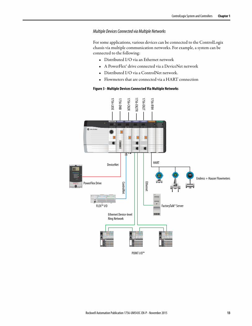
Multiple Devices Connected via Multiple Networks
For some applications, various devices can be connected to the ControlLogix chassis via multiple communication networks. For example, a system can be connected to the following:
• Distributed I/O via an Ethernet network• A PowerFlex® drive connected via a DeviceNet network• Distributed I/O via a ControlNet network.• Flowmeters that are connected via a HART connection
Figure 3 - Multiple Devices Connected Via Multiple Networks
PowerFlex Drive
DeviceNet
FLEX™ I/O
ControlNet
Ethernet Device-level Ring Network
Ethernet
HART
Endress + Hauser Flowmeters
FactoryTalk® Server
POINT I/O™
1756-L85E
1756-DNB
1756-CN2R
1756-EN2TR
1756-EN2T
1756-IF8H
Rockwell Automation Publication 1756-UM543C-EN-P - November 2015 13
Chapter 1 ControlLogix System and Controllers
Design a ControlLogix System When you design a ControlLogix system, there are several system components to consider for your application. Some of these components include the following:
• I/O devices• Motion control axes and drives• Communication modules• Controllers• Chassis• Power supplies• Studio 5000® environment
For more information to design and select components for your ControlLogix system, see:
• 1756 ControlLogix Controllers Technical Data, publication 1756-TD001• 5069 I/O Modules Specifications Technical Data,
publication 5069-TD001• 1756 ControlLogix I/O Specifications Technical Data,
publication 1756-TD002
See the Additional Resources section in the preface for more information if you are designing your ControlLogix System for any of the following applications:
• Motion with Integrated Motion on the EtherNet/IP network• Motion with the use of a coordinate system
ControlLogix 5580 Controller Features
The ControlLogix 5580 controllers are part of the Logix5000™ family of controllers. The sections that follow describe the features of these ControlLogix controllers.
System, Communication, and Programming Features
This table lists the system, communication, and programming features available with ControlLogix controllers.
Feature 1756-L83E, 1756-L85E
Controller tasks • 32 tasks• 1000 programs/task• Event tasks: all event triggers
Communication ports 1 - USB port, 2.0 full-speed, Type B1 - EtherNet/IP port, 10/100/1000 Mbps
Communication options • EtherNet/IP• ControlNet• DeviceNet• Data Highway Plus™• Remote I/O• SynchLink™• Third-party process and device networks
14 Rockwell Automation Publication 1756-UM543C-EN-P - November 2015
ControlLogix System and Controllers Chapter 1
Direct connection to an EtherNet/IP Network
The controller connects directly to an EtherNet/IP network through the onboard Ethernet port, and supports 10/100/1000 Mbps network speeds. A separate Ethernet communication module is not required in the local chassis.
Secure Digital (SD) Card
The ControlLogix 5580 controllers ship with an SD card installed. We recommend that you leave the SD card installed, so if a fault occurs, diagnostic data is automatically written to the card. Rockwell Automation can then use the data to help investigate the cause of the fault.
We recommend that you use the SD card available from Rockwell Automation (catalog number 1784-SD2).
While other SD cards can be used with the controller, Rockwell Automation has not tested the use of those cards with the controller. If you use an SD card other than those cards that are available from Rockwell Automation, you can experience data corruption or loss.
SD cards that are not provided by Rockwell Automation can have different industrial, environmental, and certification ratings as those cards that are available from Rockwell Automation. These cards can have difficulty with survival in the same industrial environments as the industrially rated versions available from Rockwell Automation.
EtherNet/IP nodes supported, max 1756-L83E: 1001756-L85E: 300
Integrated motion • Integrated Motion on the EtherNet/IP network
Programming languages • Ladder Diagram (LD)• Structured text (ST)• Function Block Diagram (FBD)• Sequential Function Chart (SFC)
Feature 1756-L83E, 1756-L85E
Rockwell Automation Publication 1756-UM543C-EN-P - November 2015 15

Chapter 1 ControlLogix System and Controllers
Notes:
16 Rockwell Automation Publication 1756-UM543C-EN-P - November 2015
Chapter 2
Configure Communication Drivers on your Workstation
Before you can connect to the controller through the EtherNet/IP or USB port, you must configure the EtherNet/IP or USB driver in RSLinx® software on your workstation.
A workstation needs at least one of these drivers to perform these tasks:
• Upload and download Studio 5000® environment project information to controllers.
• Connecting RSNetWorx™ for EtherNet/IP to the Ethernet network for online monitoring of network resource utilization.
• Collect controller data for electronic operator interfaces over an Ethernet network. For example, PanelView™ Plus terminals and FactoryTalk® View visualization software.
• Update the firmware on the controller via ControlFlash or Studio 5000 Logix Designer® programming software.
A workstation running Studio 5000 Logix Designer programming software can use either the EtherNet/IP or USB communication driver:
• The Ethernet drivers support run-time communications such as electronic operator interfaces.
• Ethernet drivers require that both the workstation and the controller have been configured.
• Ethernet drivers allow communications over longer distances.
• USB is a convenient method to connect to an unconfigured controller, so that you can configure the Ethernet port on the controller.
• USB is a convenient method to connect to a controller when the Ethernet port configuration is unknown.
• USB should not be used for run-time connections (such as electronic operator interfaces); it is a temporary-use only connection with a limited cabling distance.
Topic Page
Configure the Ethernet Communication Driver in RSLinx Classic Software 18
Configure the USB Communication Driver in RSLinx Classic Software 20
Rockwell Automation Publication 1756-UM543C-EN-P - November 2015 17
Chapter 2 Configure Communication Drivers on your Workstation
Configure the Ethernet Communication Driver in RSLinx Classic Software
Before you add a driver, confirm that these conditions exist:
• The workstation is properly connected to the Ethernet network.
• The IP address and other network parameters are correctly configured for the workstation.
To configure the EtherNet/IP driver, follow these steps.
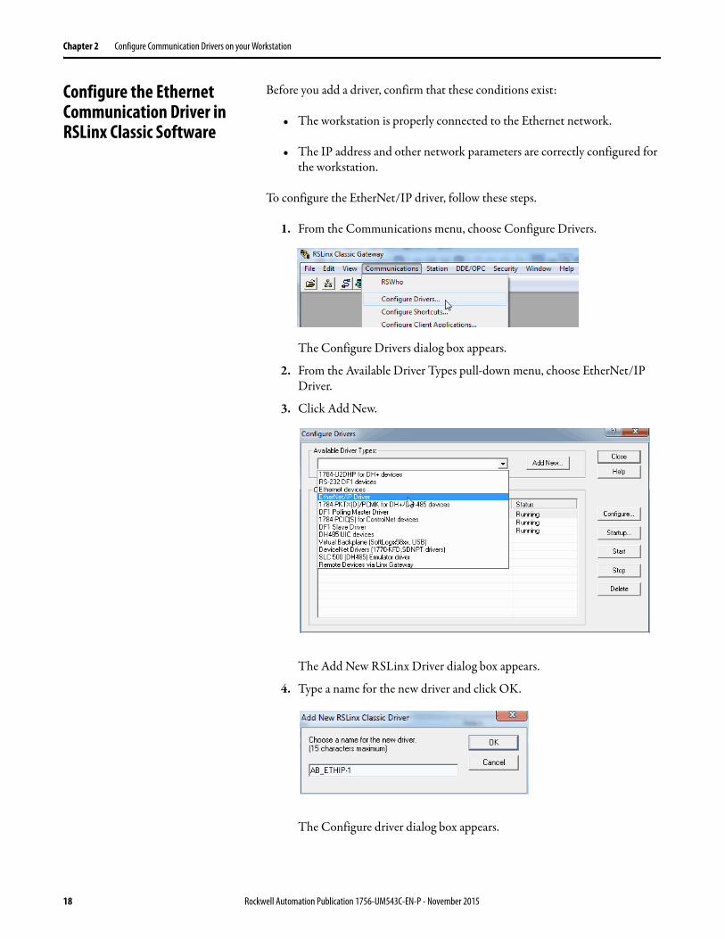
1. From the Communications menu, choose Configure Drivers.
The Configure Drivers dialog box appears.
2. From the Available Driver Types pull-down menu, choose EtherNet/IP Driver.
3. Click Add New.
The Add New RSLinx Driver dialog box appears.
4. Type a name for the new driver and click OK.
The Configure driver dialog box appears.
18 Rockwell Automation Publication 1756-UM543C-EN-P - November 2015
Configure Communication Drivers on your Workstation Chapter 2
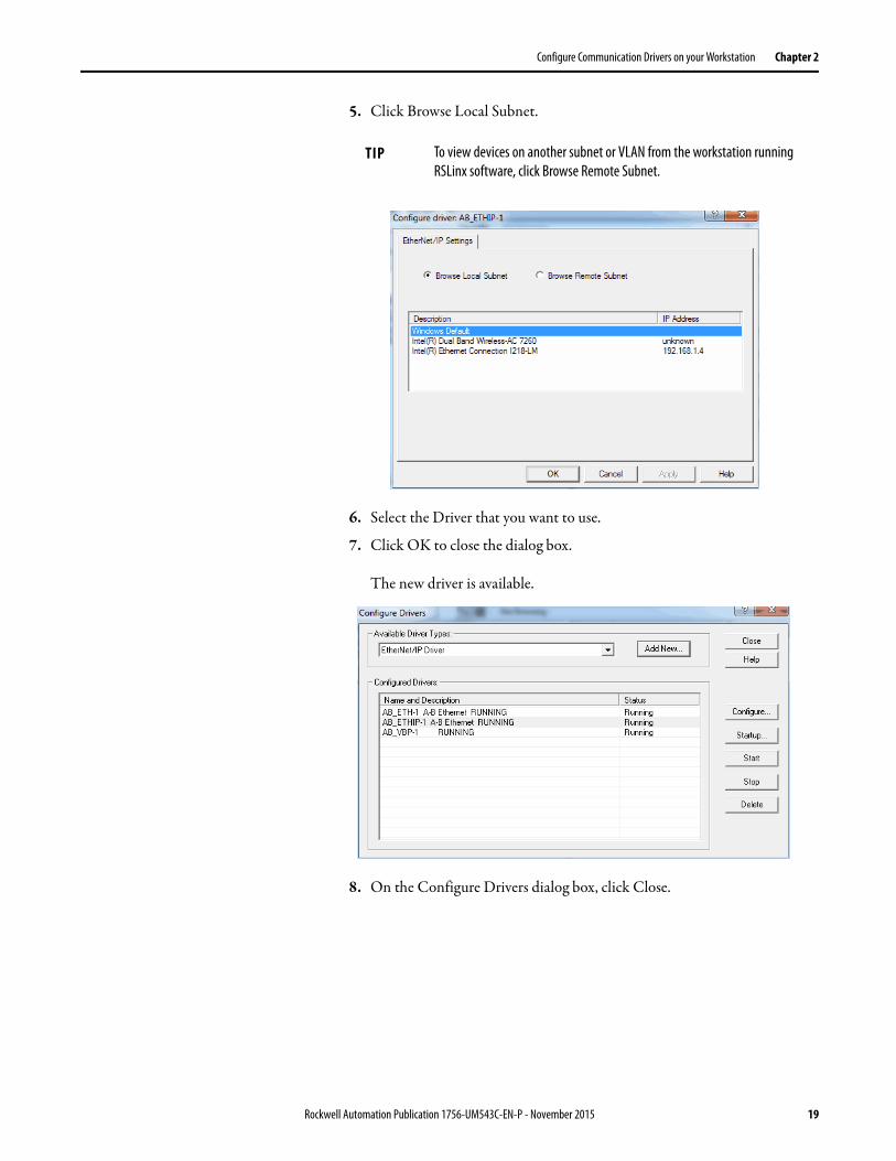
5. Click Browse Local Subnet.
6. Select the Driver that you want to use.
7. Click OK to close the dialog box.
The new driver is available.
8. On the Configure Drivers dialog box, click Close.
TIP To view devices on another subnet or VLAN from the workstation running RSLinx software, click Browse Remote Subnet.
Rockwell Automation Publication 1756-UM543C-EN-P - November 2015 19
Chapter 2 Configure Communication Drivers on your Workstation
Configure the USB Communication Driver in RSLinx Classic Software
To configure RSLinx software to use a USB port, you must first configure a USB driver.
To configure a USB driver, perform this procedure.
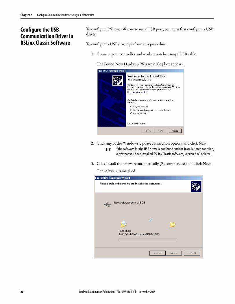
1. Connect your controller and workstation by using a USB cable.
The Found New Hardware Wizard dialog box appears.
2. Click any of the Windows Update connection options and click Next.
3. Click Install the software automatically (Recommended) and click Next.
The software is installed.
TIP If the software for the USB driver is not found and the installation is canceled, verify that you have installed RSLinx Classic software, version 3.80 or later.
20 Rockwell Automation Publication 1756-UM543C-EN-P - November 2015
Configure Communication Drivers on your Workstation Chapter 2
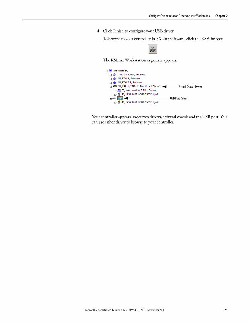
4. Click Finish to configure your USB driver.
To browse to your controller in RSLinx software, click the RSWho icon.
The RSLinx Workstation organizer appears.
Your controller appears under two drivers, a virtual chassis and the USB port. You can use either driver to browse to your controller.
Virtual Chassis Driver
USB Port Driver
Rockwell Automation Publication 1756-UM543C-EN-P - November 2015 21

Chapter 2 Configure Communication Drivers on your Workstation
Notes:
22 Rockwell Automation Publication 1756-UM543C-EN-P - November 2015
Chapter 3
Start Using the Controller
Connect to the Controller Before you can begin using your controller, you must make a connection to the controller. Make sure you have already configured the EtherNet/IP or USB communication drivers (see Configure Communication Drivers on your Workstation on page 17)
Connection options with the ControlLogix® 5580 controller include the following:
• The controller has an Ethernet port that supports 10/100/1000 Mbps. See Connect to an EtherNet/IP Network on page 24.
• The controller has a USB port that uses a Type B receptacle. The port is USB 2.0 compatible and runs at 12 Mbps. See Connect a USB Cable on page 29.
• Install and configure a communication module in the chassis with the controller as described in the installation instructions for the communication module.
Topic Page
Connect to the Controller 23
Update Controller Firmware 30
Create a Logix Designer Application Project 36
Go Online with the Controller 37
Download to the Controller 39
Upload from the Controller 40
Choose the Controller Operation Mode 43
Load or Store to the Memory Card 46
Reset Button 52
Disable the Ethernet Port 55
Rockwell Automation Publication 1756-UM543C-EN-P - November 2015 23
Chapter 3 Start Using the Controller
Connect to an EtherNet/IP Network
If you are connecting the controller directly to an EtherNet/IP network, then connect a CAT 5e or CAT 6 Ethernet cable with an RJ45 connector to the Ethernet port on the controller.
For information on how to select the proper cable, see Guidance for Selecting Cables for EtherNet/IP Networks, publication ENET-WP007-EN-P.
Determine Network Parameters
To operate an EtherNet/IP network, you must define these parameters.
If you use DNS addressing, or reference the controller via host name in MSG instructions, define these parameters.
Check with your Ethernet network administrator to determine if you must specify these parameters.
WARNING: If you connect or disconnect the communications cable with power applied to this module or any device on the network, an electrical arc can occur. This could cause an explosion in hazardous location installations. Be sure that power is removed or the area is nonhazardous before proceeding.
EtherNet/IP Network Parameter Description
IP address The IP address uniquely identifies the module. The IP address is in the form xxx.xxx.xxx.xxx where each xxx is a number from 000…255.There are some reserved values that you cannot use as the first octet in the address. These numbers are examples of values you cannot use:• 001.xxx.xxx.xxx• 127.xxx.xxx.xxx• 223 to 255.xxx.xxx.xxxThe specific reserved values that cannot be used vary according to the conditions of each application. The previous values are only examples of reserved values.
Subnet mask The subnet mask divides IP addresses into a network address and a host address. It defines whether the controller exchanges Ethernet packets directly with another device, or whether it routes packets through the Gateway. This field is set to 0.0.0.0 by default.
Gateway A gateway connects individual physical networks into a system of networks. When a node communicates with a node on another network, a gateway transfers the data between the two networks. This field is set to 0.0.0.0 by default.
Table 1 - EtherNet/IP Network Parameters for DNS Addressing
EtherNet/IP Network Parameter Description
Host name A host name is part of a text address that identifies the host for a module. The full text address of a module is host_name.domain_name.
Domain name A domain name is part of a text address that identifies the domain in which the module resides. The full text address of a module is host_name.domain_name. The domain name has a 48-character limit.If you specify a DNS server, you must type a domain name. Also, if you send email from the module, some mail relay servers require a domain name during the initial handshake of the SMTP session.
Primary DNS server address An address that an identifies any DNS servers that are used in the network. You must have a DNS server if you specified a domain name or a host name in the module configuration. The DNS server converts the domain name or host name to an IP address that is used by the network.For more information on DNS addressing, see page 28.
Secondary DNS server address
24 Rockwell Automation Publication 1756-UM543C-EN-P - November 2015
Start Using the Controller Chapter 3
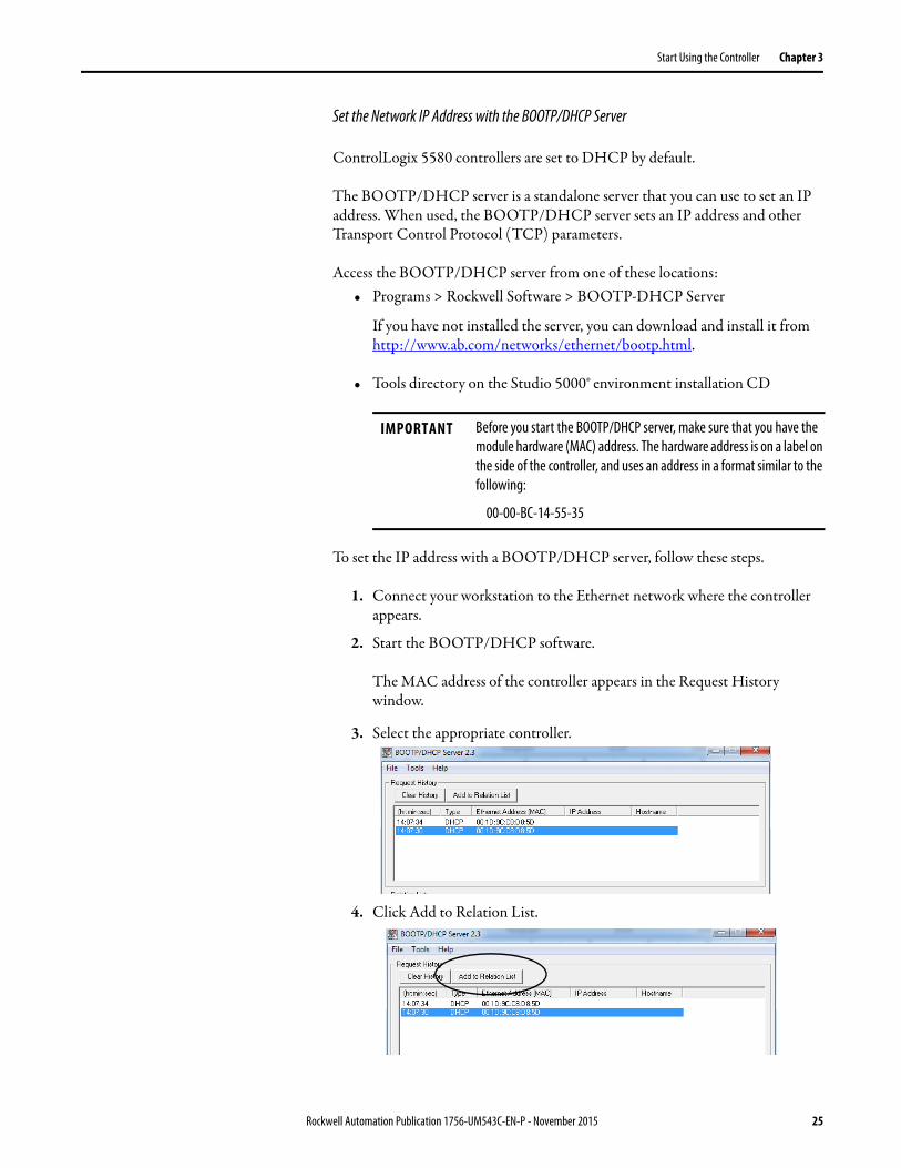
Set the Network IP Address with the BOOTP/DHCP Server
ControlLogix 5580 controllers are set to DHCP by default.
The BOOTP/DHCP server is a standalone server that you can use to set an IP address. When used, the BOOTP/DHCP server sets an IP address and other Transport Control Protocol (TCP) parameters.
Access the BOOTP/DHCP server from one of these locations:• Programs > Rockwell Software > BOOTP-DHCP Server
If you have not installed the server, you can download and install it from http://www.ab.com/networks/ethernet/bootp.html.
• Tools directory on the Studio 5000® environment installation CD
To set the IP address with a BOOTP/DHCP server, follow these steps.
1. Connect your workstation to the Ethernet network where the controller appears.
2. Start the BOOTP/DHCP software.
The MAC address of the controller appears in the Request History window.
3. Select the appropriate controller.
4. Click Add to Relation List.
IMPORTANT Before you start the BOOTP/DHCP server, make sure that you have the module hardware (MAC) address. The hardware address is on a label on the side of the controller, and uses an address in a format similar to the following:
00-00-BC-14-55-35
Rockwell Automation Publication 1756-UM543C-EN-P - November 2015 25
Chapter 3 Start Using the Controller
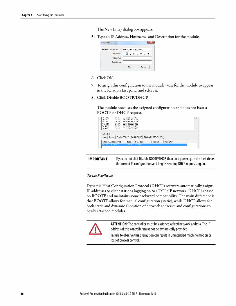
The New Entry dialog box appears.
5. Type an IP Address, Hostname, and Description for the module.
6. Click OK.
7. To assign this configuration to the module, wait for the module to appear in the Relation List panel and select it.
8. Click Disable BOOTP/DHCP.
The module now uses the assigned configuration and does not issue a BOOTP or DHCP request.
Use DHCP Software
Dynamic Host Configuration Protocol (DHCP) software automatically assigns IP addresses to client stations logging on to a TCP/IP network. DHCP is based on BOOTP and maintains some backward compatibility. The main difference is that BOOTP allows for manual configuration (static), while DHCP allows for both static and dynamic allocation of network addresses and configurations to newly attached modules.
IMPORTANT If you do not click Disable BOOTP/DHCP, then on a power cycle the host clears the current IP configuration and begins sending DHCP requests again.
ATTENTION: The controller must be assigned a fixed network address. The IP address of this controller must not be dynamically provided.Failure to observe this precaution can result in unintended machine motion or loss of process control.
26 Rockwell Automation Publication 1756-UM543C-EN-P - November 2015

Start Using the Controller Chapter 3
Duplicate IP Address Detection
The controller verifies that its IP address does not match any other network device IP address when you perform either of these tasks:
• Connect the module to a EtherNet/IP network.
• Change the controller IP address.
If the controller IP address matches that of another device on the network, the controller EtherNet/IP port transitions to Conflict mode. In Conflict mode, these conditions exist:
• Network (NET) status indicator is solid red.
• The 4-character display indicates the conflict.
The display scrolls: <IP_address_of_this_module> Duplicate IP <Mac_address_of_duplicate_node_detected>
For example: 192.168.1.1 Duplicate IP - 00:00:BC:02:34:B4
Duplicate IP Address Resolution
When two devices on a network have IP addresses that conflict, the resolution depends on the conditions in which the duplication is detected. This table describes how duplicate IP addresses are resolved.
Duplicate IP Address Detection Conditions Resolution Process
• Both devices support duplicate IP address detection.• Second device is added to the network after the first
device is operating on the network.
1. The device that began operation first uses the IP address and continues to operate without interruption.2. The device that begins operation second detects the duplication and enters Conflict mode.
To assign a new IP address to the controller and leave Conflict mode, see Set the Network IP Address with the BOOTP/DHCP Server on page 25.
• Both devices support duplicate IP address detection• Both devices were powered up at approximately the
same time.
Both EtherNet/IP devices enter Conflict mode.To resolve this conflict, follow these steps:
a. Assign a new IP address to the controller. See Set the Network IP Address with the BOOTP/DHCP Server on page 25.b. Cycle power to the other device.
One device supports duplicate IP address detection and a second device does not
1. Regardless of which device obtained the IP address first, the device that does not support IP address detection uses the IP address and continues to operate without interruption.
2. The device that supports duplicate IP address detection detects the duplication and enters Conflict mode. To assign a new IP address to the controller and leave Conflict mode, see Set the Network IP Address with the BOOTP/DHCP Server on page 25.
Rockwell Automation Publication 1756-UM543C-EN-P - November 2015 27
Chapter 3 Start Using the Controller
DNS Addressing
You can also use DNS addressing to specify a host name for a controller, a domain name, and DNS servers. DNS addressing makes it possible to configure similar network structures and IP address sequences under different domains.
DNS addressing is necessary only if you refer to the controller by host name, such as in path descriptions in MSG instructions.
To use DNS addressing, follow these steps.
1. Assign a host name to the controller.
A network administrator can assign a host name. Valid host names must be IEC-1131-3 compliant.
2. Configure the controller parameters.
3. Configure the IP address, subnet mask, gateway address, a host name for the controller, domain name, and primary/secondary DNS server addresses.
In the DNS server, the host name must match the IP address of the controller.
4. In the Studio 5000 environment, add the controller to the I/O configuration tree.
IMPORTANT If a child module resides in the same domain as its parent module, type the host name. If the domain of the child module differs from the domain of its parent module, type the host name and the domain name (hostname.domainname)
IMPORTANT You can also use DNS addressing in a module profile in the I/O controller tree or in a message path. If the domain name of the destination module differs from the domain name of the source module, then use a fully qualified DNS name (hostname.domainname). For example, to send a message from EN2T1.location1.companyA to EN2T1.location2.companyA, the host names match, but the domains differ. Without the entry of a fully qualified DNS name, the module adds the default domain name to the specified host name.
28 Rockwell Automation Publication 1756-UM543C-EN-P - November 2015
Start Using the Controller Chapter 3
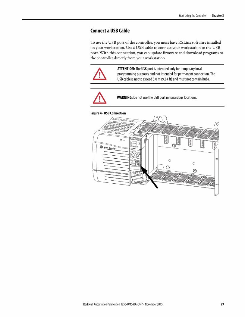
Connect a USB Cable
To use the USB port of the controller, you must have RSLinx software installed on your workstation. Use a USB cable to connect your workstation to the USB port. With this connection, you can update firmware and download programs to the controller directly from your workstation.
Figure 4 - USB Connection
ATTENTION: The USB port is intended only for temporary local programming purposes and not intended for permanent connection. The USB cable is not to exceed 3.0 m (9.84 ft) and must not contain hubs.
WARNING: Do not use the USB port in hazardous locations.
Logix5585
REMRUN
PROG
!
0 0 0 0NET
LINK
RUN FORCE OKSD
Rockwell Automation Publication 1756-UM543C-EN-P - November 2015 29
Chapter 3 Start Using the Controller
Update Controller Firmware You can choose to update controller firmware by using one of these tools:• ControlFLASH™ software that is packaged with the Studio 5000
environment• AutoFlash feature of the Logix Designer application
To update your controller firmware, complete the tasks that are listed in this table.
Determine Required Controller Firmware
Use Table 2 to determine what firmware revision is required for your controller.
Obtain Controller Firmware
Controller firmware is packaged with the Studio 5000 environment. You can also download controller firmware from the Rockwell Automation Product Compatibility and Download website at http://www.rockwellautomation.com/support/pcdc.page.
Task Page
Determine Required Controller Firmware 30
Obtain Controller Firmware 30
Use ControlFLASH Software to Update Firmware 31
Use AutoFlash to Update Firmware 34
IMPORTANT The controller must be in Remote Program or Program mode and all major recoverable faults must be cleared to accept updates.
Table 2 - Firmware Required for Controllers
Controller Series Use this Firmware Revision
1756-L83E, 1756-L85E B Version 28 or later
30 Rockwell Automation Publication 1756-UM543C-EN-P - November 2015
Start Using the Controller Chapter 3
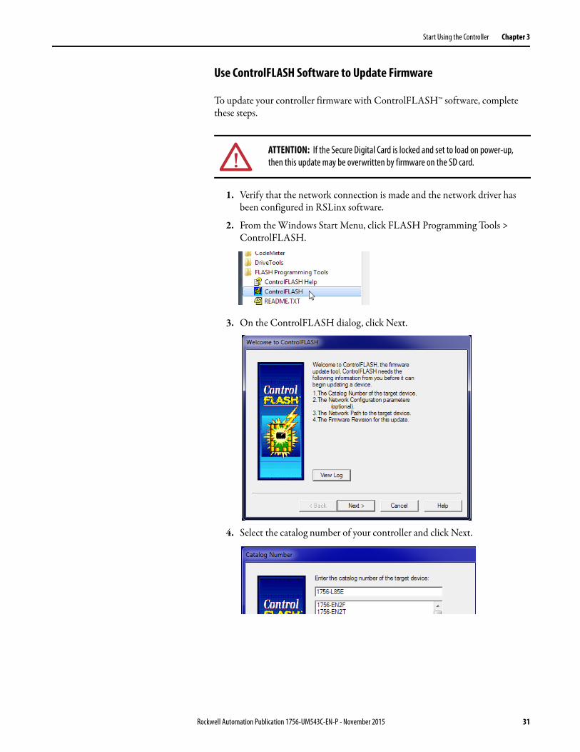
Use ControlFLASH Software to Update Firmware
To update your controller firmware with ControlFLASH™ software, complete these steps.
1. Verify that the network connection is made and the network driver has been configured in RSLinx software.
2. From the Windows Start Menu, click FLASH Programming Tools > ControlFLASH.
3. On the ControlFLASH dialog, click Next.
4. Select the catalog number of your controller and click Next.
ATTENTION: If the Secure Digital Card is locked and set to load on power-up, then this update may be overwritten by firmware on the SD card.
Rockwell Automation Publication 1756-UM543C-EN-P - November 2015 31
Chapter 3 Start Using the Controller
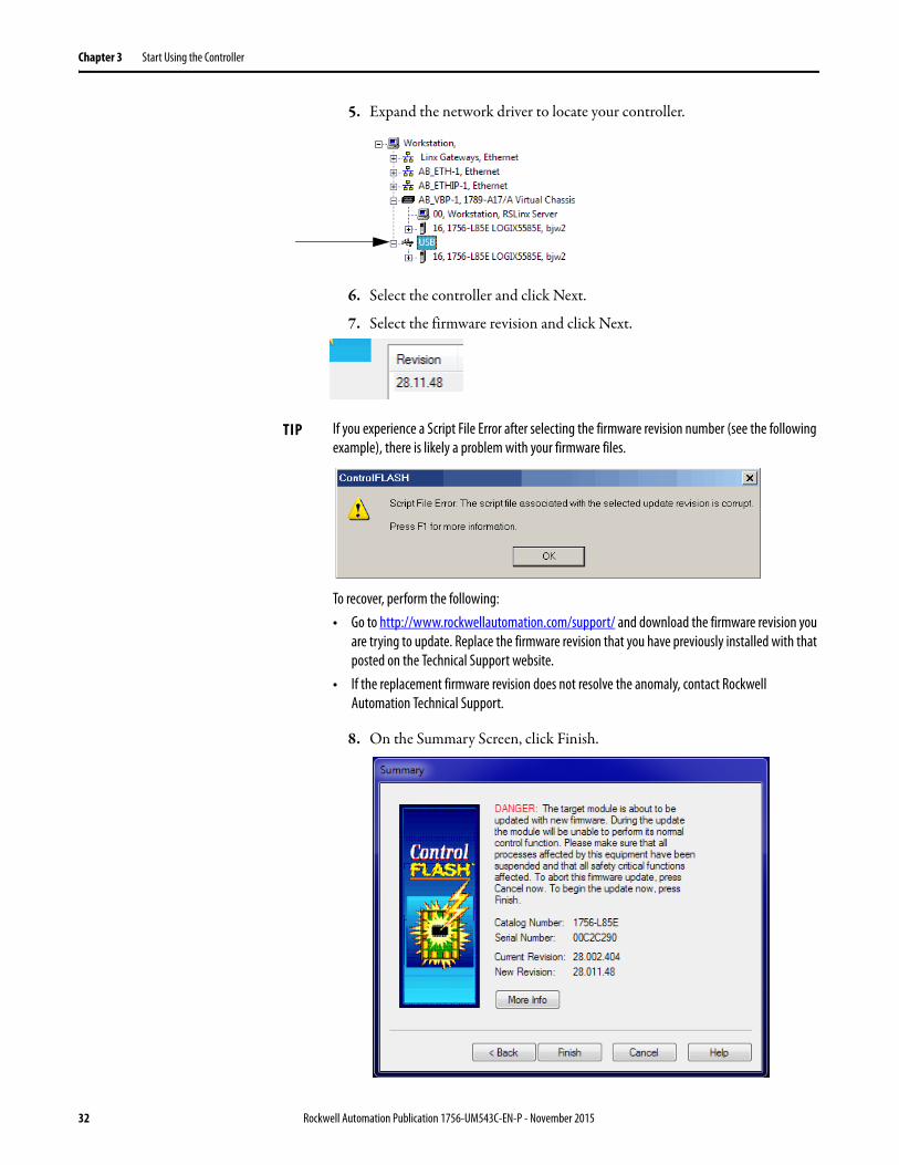
5. Expand the network driver to locate your controller.
6. Select the controller and click Next.
7. Select the firmware revision and click Next..
8. On the Summary Screen, click Finish.
TIP If you experience a Script File Error after selecting the firmware revision number (see the following example), there is likely a problem with your firmware files.
To recover, perform the following:• Go to http://www.rockwellautomation.com/support/ and download the firmware revision you
are trying to update. Replace the firmware revision that you have previously installed with that posted on the Technical Support website.
• If the replacement firmware revision does not resolve the anomaly, contact Rockwell Automation Technical Support.
32 Rockwell Automation Publication 1756-UM543C-EN-P - November 2015
Start Using the Controller Chapter 3
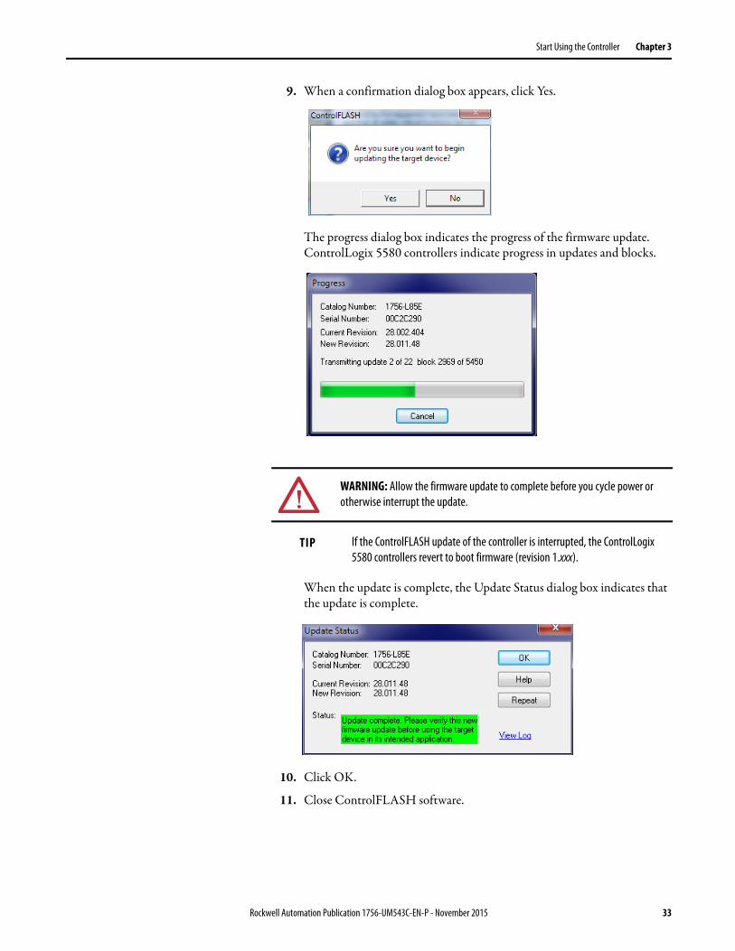
9. When a confirmation dialog box appears, click Yes.
The progress dialog box indicates the progress of the firmware update. ControlLogix 5580 controllers indicate progress in updates and blocks.
When the update is complete, the Update Status dialog box indicates that the update is complete.
10. Click OK.
11. Close ControlFLASH software.
WARNING: Allow the firmware update to complete before you cycle power or otherwise interrupt the update.
TIP If the ControlFLASH update of the controller is interrupted, the ControlLogix 5580 controllers revert to boot firmware (revision 1.xxx).
Rockwell Automation Publication 1756-UM543C-EN-P - November 2015 33

Chapter 3 Start Using the Controller
Use AutoFlash to Update Firmware
To update your controller firmware with the AutoFlash feature, complete these steps.
1. Verify that the network connection is made and your network driver is configured in RSLinx software.
2. Use the Logix Designer application to create a controller project. See Create a Logix Designer Application Project on page 36.
3. On the Logix Designer Path bar, click Who Active.
4. On the Who Active dialog box, select your controller under the communication driver you want to use, and click Update Firmware.
.
5. On the Choose Firmware Revision dialog, browse to the location of the firmware files (C:\Program Files (x86)\ControlFlash).
6. Select the firmware revision, and click Update.
ATTENTION: If the Secure Digital Card is locked and set to load on power-up, then this update may be overwritten by firmware on the SD card.
34 Rockwell Automation Publication 1756-UM543C-EN-P - November 2015

Start Using the Controller Chapter 3
7. On the Confirmation dialog, click Yes.
8. On the ControlFlash Attention dialog, click OK.
The firmware update begins.
Allow the firmware update to complete without interruption.
When the firmware update is complete, the progress dialog closes.
Rockwell Automation Publication 1756-UM543C-EN-P - November 2015 35
Chapter 3 Start Using the Controller
Create a Logix Designer Application Project
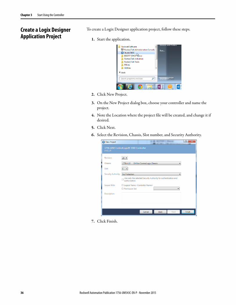
To create a Logix Designer application project, follow these steps.
1. Start the application.
2. Click New Project.
3. On the New Project dialog box, choose your controller and name the project.
4. Note the Location where the project file will be created, and change it if desired.
5. Click Next.
6. Select the Revision, Chassis, Slot number, and Security Authority.
7. Click Finish.
36 Rockwell Automation Publication 1756-UM543C-EN-P - November 2015
Start Using the Controller Chapter 3
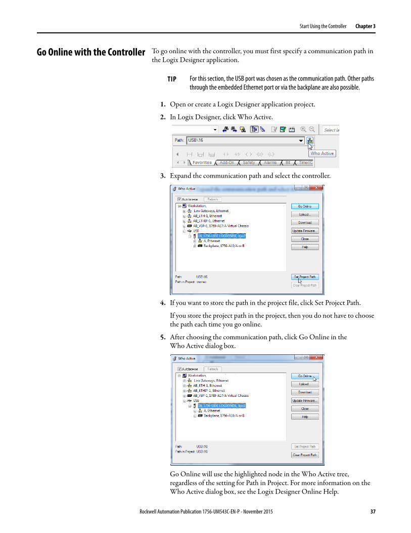
Go Online with the Controller To go online with the controller, you must first specify a communication path in the Logix Designer application.
1. Open or create a Logix Designer application project.
2. In Logix Designer, click Who Active.
3. Expand the communication path and select the controller.
4. If you want to store the path in the project file, click Set Project Path.
If you store the project path in the project, then you do not have to choose the path each time you go online.
5. After choosing the communication path, click Go Online in the Who Active dialog box.
Go Online will use the highlighted node in the Who Active tree, regardless of the setting for Path in Project. For more information on the Who Active dialog box, see the Logix Designer Online Help.
TIP For this section, the USB port was chosen as the communication path. Other paths through the embedded Ethernet port or via the backplane are also possible.
Rockwell Automation Publication 1756-UM543C-EN-P - November 2015 37

Chapter 3 Start Using the Controller
You can also select a recent communications path and go online or apply it to your project.
1. In Logix Designer, click the arrow that is on the Path bar.
2. On the Select Recent Communications Path dialog box, choose the path.
3. Click Set Project Path to store the path in your project.
4. Click Go Online.
For more information on the Select Recent Communications Path dialog box, see the Logix Designer Online Help.
Once you have established a communication path, then you can choose Go Online from the Controller Status menu when you are working in the project.
38 Rockwell Automation Publication 1756-UM543C-EN-P - November 2015
Start Using the Controller Chapter 3
Download to the Controller When you download a project to the controller, it copies the project from the Logix Designer application onto the controller. You can download a project in two ways:
• Use the Who Active Dialog Box to Download on page 39• Use the Controller Status Menu to Download on page 40
Use the Who Active Dialog Box to Download
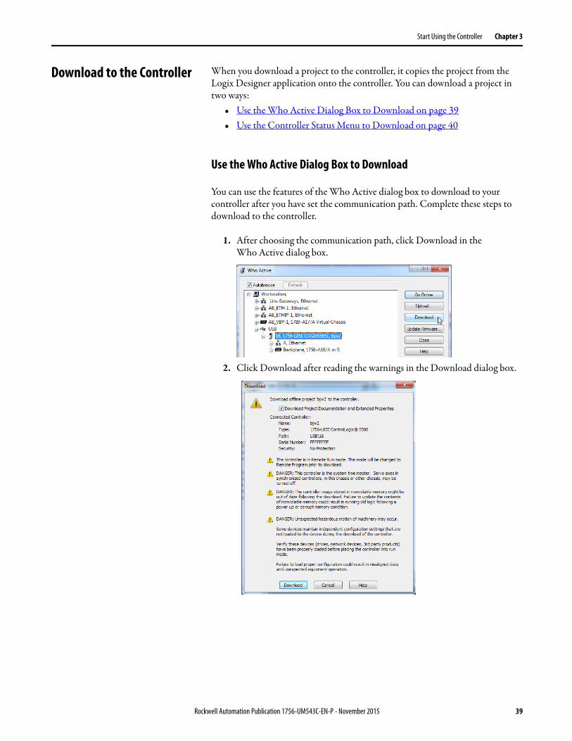
You can use the features of the Who Active dialog box to download to your controller after you have set the communication path. Complete these steps to download to the controller.
1. After choosing the communication path, click Download in the Who Active dialog box.
2. Click Download after reading the warnings in the Download dialog box.
Rockwell Automation Publication 1756-UM543C-EN-P - November 2015 39
Chapter 3 Start Using the Controller
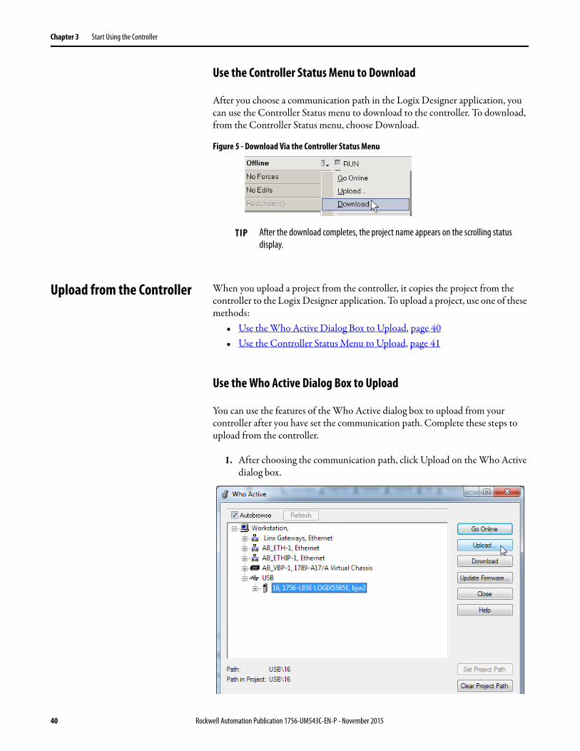
Use the Controller Status Menu to Download
After you choose a communication path in the Logix Designer application, you can use the Controller Status menu to download to the controller. To download, from the Controller Status menu, choose Download.
Figure 5 - Download Via the Controller Status Menu
Upload from the Controller When you upload a project from the controller, it copies the project from the controller to the Logix Designer application. To upload a project, use one of these methods:
• Use the Who Active Dialog Box to Upload, page 40• Use the Controller Status Menu to Upload, page 41
Use the Who Active Dialog Box to Upload
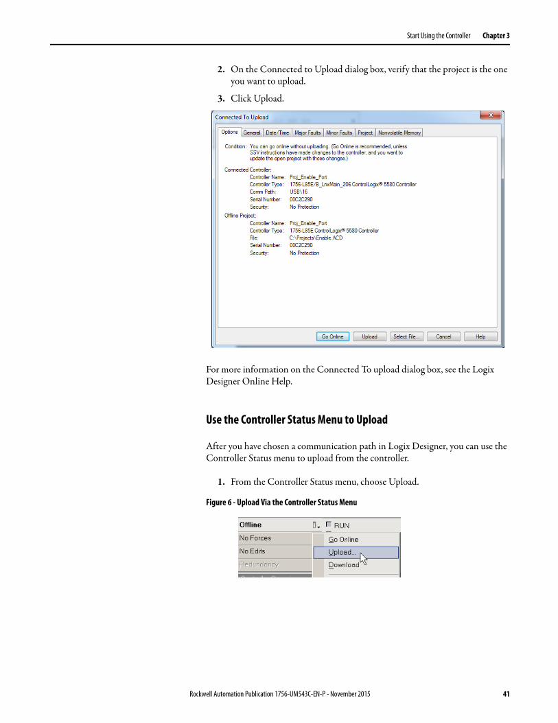
You can use the features of the Who Active dialog box to upload from your controller after you have set the communication path. Complete these steps to upload from the controller.
1. After choosing the communication path, click Upload on the Who Active dialog box.
TIP After the download completes, the project name appears on the scrolling status display.
40 Rockwell Automation Publication 1756-UM543C-EN-P - November 2015
Start Using the Controller Chapter 3
2. On the Connected to Upload dialog box, verify that the project is the one you want to upload.
3. Click Upload.
For more information on the Connected To upload dialog box, see the Logix Designer Online Help.
Use the Controller Status Menu to Upload
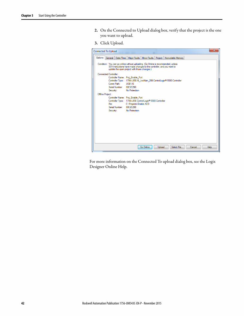
After you have chosen a communication path in Logix Designer, you can use the Controller Status menu to upload from the controller.
1. From the Controller Status menu, choose Upload.
Figure 6 - Upload Via the Controller Status Menu
Rockwell Automation Publication 1756-UM543C-EN-P - November 2015 41
Chapter 3 Start Using the Controller
2. On the Connected to Upload dialog box, verify that the project is the one you want to upload.
3. Click Upload.
For more information on the Connected To upload dialog box, see the Logix Designer Online Help.
42 Rockwell Automation Publication 1756-UM543C-EN-P - November 2015
Start Using the Controller Chapter 3
Choose the Controller Operation Mode
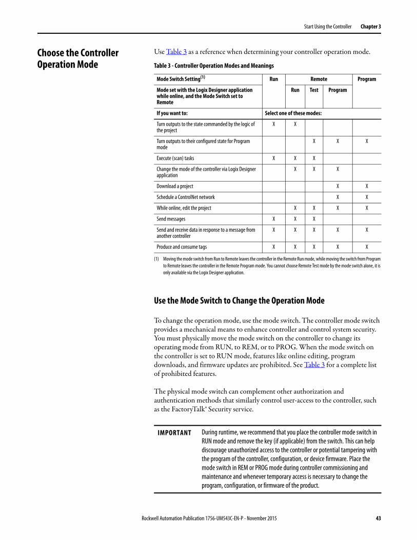
Use Table 3 as a reference when determining your controller operation mode.
Use the Mode Switch to Change the Operation Mode
To change the operation mode, use the mode switch. The controller mode switch provides a mechanical means to enhance controller and control system security. You must physically move the mode switch on the controller to change its operating mode from RUN, to REM, or to PROG. When the mode switch on the controller is set to RUN mode, features like online editing, program downloads, and firmware updates are prohibited. See Table 3 for a complete list of prohibited features.
The physical mode switch can complement other authorization and authentication methods that similarly control user-access to the controller, such as the FactoryTalk® Security service.
Table 3 - Controller Operation Modes and Meanings
Mode Switch Setting(1)
(1) Moving the mode switch from Run to Remote leaves the controller in the Remote Run mode, while moving the switch from Program to Remote leaves the controller in the Remote Program mode. You cannot choose Remote Test mode by the mode switch alone, it is only available via the Logix Designer application.
Run Remote Program
Mode set with the Logix Designer application while online, and the Mode Switch set to Remote
Run Test Program
If you want to: Select one of these modes:
Turn outputs to the state commanded by the logic of the project
X X
Turn outputs to their configured state for Program mode
X X X
Execute (scan) tasks X X X
Change the mode of the controller via Logix Designer application
X X X
Download a project X X
Schedule a ControlNet network X X
While online, edit the project X X X X
Send messages X X X
Send and receive data in response to a message from another controller
X X X X X
Produce and consume tags X X X X X
IMPORTANT During runtime, we recommend that you place the controller mode switch in RUN mode and remove the key (if applicable) from the switch. This can help discourage unauthorized access to the controller or potential tampering with the program of the controller, configuration, or device firmware. Place the mode switch in REM or PROG mode during controller commissioning and maintenance and whenever temporary access is necessary to change the program, configuration, or firmware of the product.
Rockwell Automation Publication 1756-UM543C-EN-P - November 2015 43
Chapter 3 Start Using the Controller
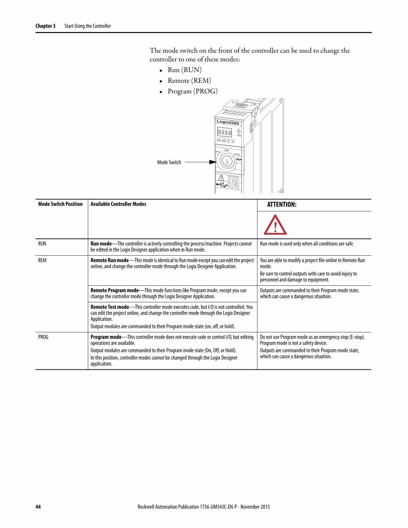
The mode switch on the front of the controller can be used to change the controller to one of these modes:
• Run (RUN)• Remote (REM)• Program (PROG)
Mode Switch
Mode Switch Position Available Controller Modes ATTENTION:
RUN Run mode—The controller is actively controlling the process/machine. Projects cannot be edited in the Logix Designer application when in Run mode.
Run mode is used only when all conditions are safe.
REM Remote Run mode—This mode is identical to Run mode except you can edit the project online, and change the controller mode through the Logix Designer Application.
You are able to modify a project file online in Remote Run mode.Be sure to control outputs with care to avoid injury to personnel and damage to equipment.
Remote Program mode—This mode functions like Program mode, except you can change the controller mode through the Logix Designer Application.
Outputs are commanded to their Program mode state, which can cause a dangerous situation.
Remote Test mode—This controller mode executes code, but I/O is not controlled. You can edit the project online, and change the controller mode through the Logix Designer Application.Output modules are commanded to their Program mode state (on, off, or hold).
PROG Program mode—This controller mode does not execute code or control I/O, but editing operations are available.Output modules are commanded to their Program mode state (On, Off, or Hold).In this position, controller modes cannot be changed through the Logix Designer application.
Do not use Program mode as an emergency stop (E-stop). Program mode is not a safety device.Outputs are commanded to their Program mode state, which can cause a dangerous situation.
44 Rockwell Automation Publication 1756-UM543C-EN-P - November 2015
Start Using the Controller Chapter 3
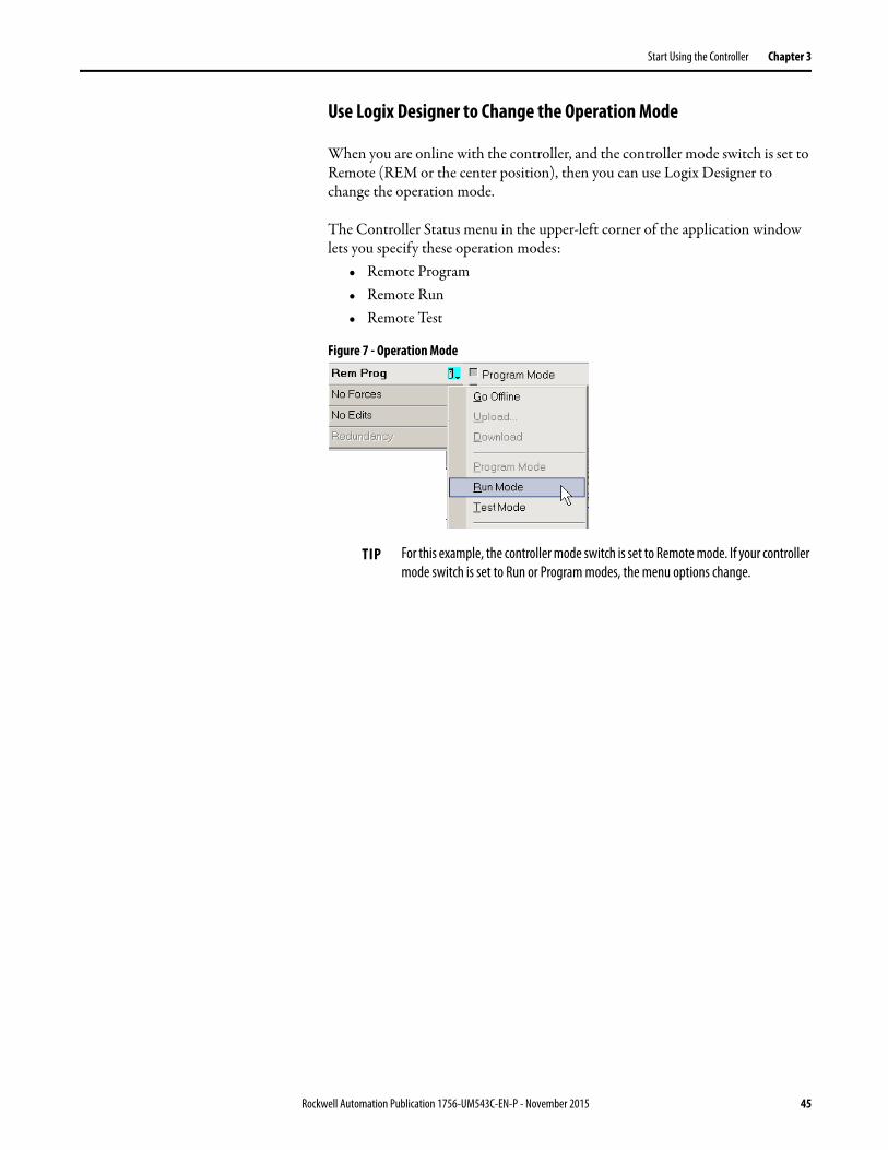
Use Logix Designer to Change the Operation Mode
When you are online with the controller, and the controller mode switch is set to Remote (REM or the center position), then you can use Logix Designer to change the operation mode.
The Controller Status menu in the upper-left corner of the application window lets you specify these operation modes:
• Remote Program• Remote Run• Remote Test
Figure 7 - Operation Mode
TIP For this example, the controller mode switch is set to Remote mode. If your controller mode switch is set to Run or Program modes, the menu options change.
Rockwell Automation Publication 1756-UM543C-EN-P - November 2015 45
Chapter 3 Start Using the Controller
Load or Store to the Memory Card
The memory card that is compatible with your ControlLogix controller is used to load or store the contents of user memory for the controller.
Store to the Memory Card
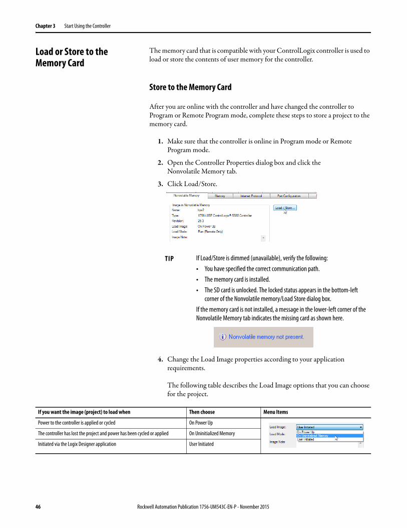
After you are online with the controller and have changed the controller to Program or Remote Program mode, complete these steps to store a project to the memory card.
1. Make sure that the controller is online in Program mode or Remote Program mode.
2. Open the Controller Properties dialog box and click the Nonvolatile Memory tab.
3. Click Load/Store.
4. Change the Load Image properties according to your application requirements.
The following table describes the Load Image options that you can choose for the project.
TIP If Load/Store is dimmed (unavailable), verify the following:• You have specified the correct communication path.• The memory card is installed.• The SD card is unlocked. The locked status appears in the bottom-left
corner of the Nonvolatile memory/Load Store dialog box.If the memory card is not installed, a message in the lower-left corner of the Nonvolatile Memory tab indicates the missing card as shown here.
If you want the image (project) to load when Then choose Menu Items
Power to the controller is applied or cycled On Power Up
The controller has lost the project and power has been cycled or applied On Uninitialized Memory
Initiated via the Logix Designer application User Initiated
46 Rockwell Automation Publication 1756-UM543C-EN-P - November 2015

Start Using the Controller Chapter 3
This table shows what happens at power up when you insert an SD card that contains an image into a ControlLogix 5580 controller.
5. Change the Load Mode properties according to your application requirements.
This table describes the Load Mode options that you can choose for the project.
6. Change the Automatic Firmware Update properties according to your application requirements. The Automatic Firmware Update property is also referred to as the Firmware Supervisor feature.
This table describes the Automatic Firmware Update options that you can choose for the project.
IMPORTANT If the SD card is locked and the Load Image option of the project is set to On Power Up, then the controller firmware is not updated as a result of a firmware update. The previously stored firmware and project are loaded instead.
Image Setting Controller is in out-of-box condition(v1.x firmware)
Firmware > 1.x and internal non-volatile memory is not valid(2)
Firmware > 1.x and internal non-volatile memory is valid(2)
User Initiated Loads Firmware Only(1) Does Nothing Does Nothing
On Power Up Loads both Firmware and Application • Loads Firmware if there is a revision mismatch• Loads Application
• Loads Firmware if there is a revision mismatch• Loads Application
On Uninitialized Memory Loads both Firmware and Application(1) • Loads Firmware if there is a revision mismatch• Loads Application
Does Nothing
(1) Indicates change in behavior from ControlLogix 5570 and older controllers.
(2) “Valid” includes th No Project condition.
If you want the controller to go to this mode after loading Then choose Menu Items
Program Program (remote only)
Run Run (remote only)
Setting Description Menu Items
Disable Disables any automatic firmware updates. This item only appears in the menu when you initially save the image.
Enable and Store Files to Image Enables automatic firmware updates for I/O devices in the configuration tree of the controller. Saves I/O device firmware and controller firmware to the image. I/O devices must be configured to use Exact Match Keying.(1)
Disable and Delete Files to Image Disables automatic firmware updates for I/O devices in the configuration tree of the controller. Removes I/O device firmware from the image, but does not remove controller firmware from image.This item only appears in the menu on subsequent saves of the image.
(1) The devices that are used with this option must support the revision of firmware being updated to.
Rockwell Automation Publication 1756-UM543C-EN-P - November 2015 47
Chapter 3 Start Using the Controller
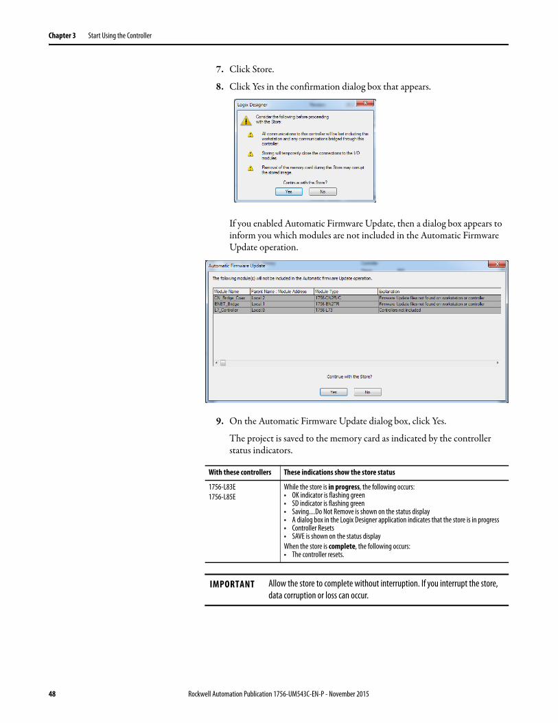
7. Click Store.
8. Click Yes in the confirmation dialog box that appears.
If you enabled Automatic Firmware Update, then a dialog box appears to inform you which modules are not included in the Automatic Firmware Update operation.
9. On the Automatic Firmware Update dialog box, click Yes.
The project is saved to the memory card as indicated by the controller status indicators.
With these controllers These indications show the store status
1756-L83E1756-L85E
While the store is in progress, the following occurs:• OK indicator is flashing green• SD indicator is flashing green• Saving....Do Not Remove is shown on the status display• A dialog box in the Logix Designer application indicates that the store is in progress• Controller Resets• SAVE is shown on the status displayWhen the store is complete, the following occurs:• The controller resets.
IMPORTANT Allow the store to complete without interruption. If you interrupt the store, data corruption or loss can occur.
48 Rockwell Automation Publication 1756-UM543C-EN-P - November 2015
Start Using the Controller Chapter 3
Load from the Memory Card
After you have set the communication path, are online with the controller, and have changed the controller to Program mode, you can load a project to the controller from the memory card.
This table shows what happens at power up when you insert an SD card that contains an image into a ControlLogix 5580 controller.
To load a project to the controller from the memory card, complete these steps.
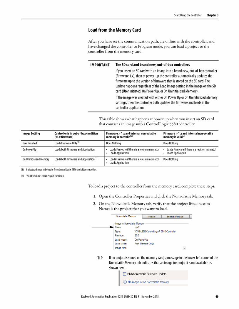
1. Open the Controller Properties and click the Nonvolatile Memory tab.
2. On the Nonvolatile Memory tab, verify that the project listed next to Name: is the project that you want to load.
IMPORTANT The SD card and brand new, out-of-box controllersIf you insert an SD card with an image into a brand new, out-of-box controller (firmware 1.x), then at power-up the controller automatically updates the firmware up to the version of firmware that is stored on the SD card. The update happens regardless of the Load Image setting in the image on the SD card (User Initiated, On Power Up, or On Uninitialized Memory).If the image was created with either On Power Up or On Uninitialized Memory settings, then the controller both updates the firmware and loads in the controller application.
Image Setting Controller is in out-of-box condition(v1.x firmware)
Firmware > 1.x and internal non-volatile memory is not valid(2)
Firmware > 1.x and internal non-volatile memory is valid(2)
User Initiated Loads Firmware Only(1) Does Nothing Does Nothing
On Power Up Loads both Firmware and Application • Loads Firmware if there is a revision mismatch• Loads Application
• Loads Firmware if there is a revision mismatch• Loads Application
On Uninitialized Memory Loads both Firmware and Application(1) • Loads Firmware if there is a revision mismatch• Loads Application
Does Nothing
(1) Indicates change in behavior from ControlLogix 5570 and older controllers.
(2) “Valid” includes th No Project condition.
TIP If no project is stored on the memory card, a message in the lower-left corner of the Nonvolatile Memory tab indicates that an image (or project) is not available as shown here.
Rockwell Automation Publication 1756-UM543C-EN-P - November 2015 49
Chapter 3 Start Using the Controller
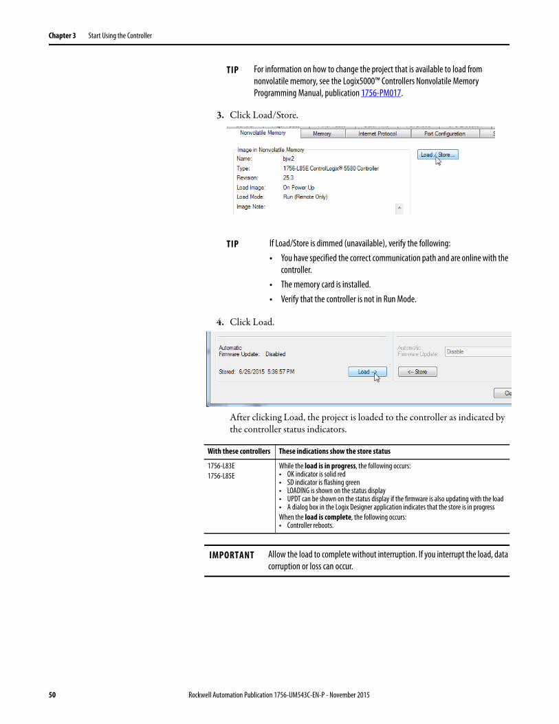
3. Click Load/Store.
4. Click Load.
After clicking Load, the project is loaded to the controller as indicated by the controller status indicators.
.
TIP For information on how to change the project that is available to load from nonvolatile memory, see the Logix5000™ Controllers Nonvolatile Memory Programming Manual, publication 1756-PM017.
TIP If Load/Store is dimmed (unavailable), verify the following:• You have specified the correct communication path and are online with the
controller.• The memory card is installed.• Verify that the controller is not in Run Mode.
With these controllers These indications show the store status
1756-L83E1756-L85E
While the load is in progress, the following occurs:• OK indicator is solid red• SD indicator is flashing green• LOADING is shown on the status display• UPDT can be shown on the status display if the firmware is also updating with the load• A dialog box in the Logix Designer application indicates that the store is in progressWhen the load is complete, the following occurs:• Controller reboots.
IMPORTANT Allow the load to complete without interruption. If you interrupt the load, data corruption or loss can occur.
50 Rockwell Automation Publication 1756-UM543C-EN-P - November 2015
Start Using the Controller Chapter 3
Other Memory Card Tasks
Other tasks that you can complete by using the memory cards of the controller include the following:
• Change the image that is loaded from the card• Check for a load that was completed• Clear an image from the memory card• Store an empty image• Change load parameters• Read/write application data to the card
For more information to complete any of these tasks, see the Logix5000 Controllers Memory Card Programming Manual, publication 1756-PM017.
Rockwell Automation Publication 1756-UM543C-EN-P - November 2015 51
Chapter 3 Start Using the Controller
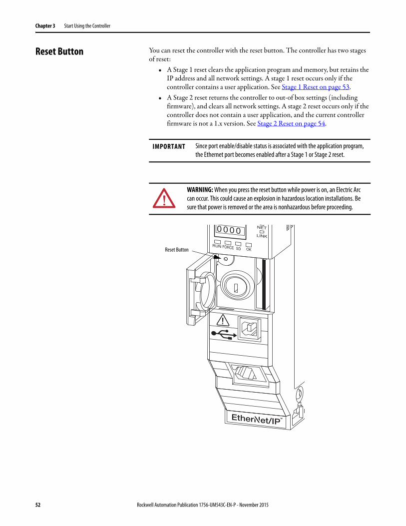
Reset Button You can reset the controller with the reset button. The controller has two stages of reset:
• A Stage 1 reset clears the application program and memory, but retains the IP address and all network settings. A stage 1 reset occurs only if the controller contains a user application. See Stage 1 Reset on page 53.
• A Stage 2 reset returns the controller to out-of box settings (including firmware), and clears all network settings. A stage 2 reset occurs only if the controller does not contain a user application, and the current controller firmware is not a 1.x version. See Stage 2 Reset on page 54.
IMPORTANT Since port enable/disable status is associated with the application program, the Ethernet port becomes enabled after a Stage 1 or Stage 2 reset.
WARNING: When you press the reset button while power is on, an Electric Arc can occur. This could cause an explosion in hazardous location installations. Be sure that power is removed or the area is nonhazardous before proceeding.
0 0 0 0
Reset Button
52 Rockwell Automation Publication 1756-UM543C-EN-P - November 2015
Start Using the Controller Chapter 3
Stage 1 Reset
The stage 1 reset:• Clears the application program.• Retains the network settings for the embedded Ethernet port.• Retains APR (motion position info) information.• Retains all PTP configuration (Time Synchronization) parameters.• Retains Wall Clock Time within the energy retention capability of the
module.• Creates a timestamped entry in the Controller Log that a Stage 1 Reset
event has occurred.• Resets the controller to begin the controller start up process.• Prevents the controller from loading firmware or software from the SD
card on this first start up after the reset, regardless of the setting on the SD card, and without modifying the SD card contents (the write-protect setting is irrelevant). An SD card will reload (if configured to do so) on subsequent powerup situations.
• Enables the Ethernet Port, if it was previously disabled.
Follow these steps to perform a stage 1 reset:
1. Power down the controller.
2. Remove the key from the keyswitch.
3. Open the front door on the controller.
4. Use a small tool with a diameter of a paper clip, to press and hold the reset button. This button is recessed 5 mm (0.19 in.) behind the panel.
5. While holding in the reset button, power up the controller.
6. Continue to hold the reset button while the 4-character display cycles through CLR, 4, 3, 2, 1, Project Cleared.
7. After Project Cleared appears, release the reset button.
If you release the reset button before Project Cleared scrolls across the display, then the controller continues with powerup and does not reset.
Rockwell Automation Publication 1756-UM543C-EN-P - November 2015 53

Chapter 3 Start Using the Controller
Stage 2 Reset
The stage 2 reset:• Returns the module to revision 1.x firmware (the out-of-box firmware
revision).• Clears all user settings to the out-of-box values including network and
time synchronization settings.• Resets the controller to begin the controller start up process.• There will be no entries in the controller log after a Stage 2 reset, but saved
logs on the SD card remain.
Follow these steps to perform a Stage 2 reset:
1. Power down the controller.
2. Remove the key from the keyswitch.
3. Open the front door on the controller.
4. Remove the SD card.
5. Use a small tool with a diameter of a paper clip, to press and hold the reset button. This button is recessed 5 mm (0.19 in.) behind the panel.
6. While holding in the reset button, power up the controller.
7. Continue to hold the reset button while the 4-character display cycles through DFLT, 4, 3, 2, 1, Factory Default
8. After Factory Default appears, release the reset button.
9. On your workstation, delete all of the files on the SD card.
10. Power down the controller.
11. Reinstall the SD card.
12. Powerup the controller.
13. Verify that the controller is at firmware revision 1.x, and the controller is set to DHCP.
54 Rockwell Automation Publication 1756-UM543C-EN-P - November 2015
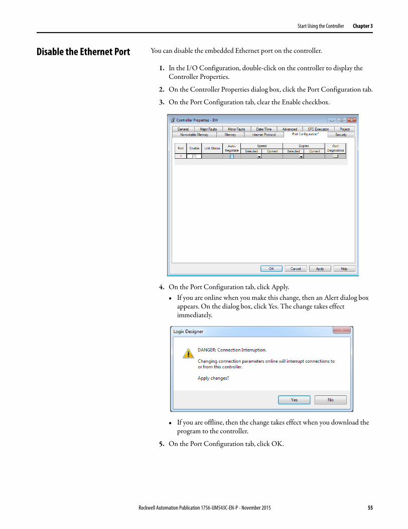
Start Using the Controller Chapter 3
Disable the Ethernet Port You can disable the embedded Ethernet port on the controller.
1. In the I/O Configuration, double-click on the controller to display the Controller Properties.
2. On the Controller Properties dialog box, click the Port Configuration tab.
3. On the Port Configuration tab, clear the Enable checkbox.
4. On the Port Configuration tab, click Apply.• If you are online when you make this change, then an Alert dialog box
appears. On the dialog box, click Yes. The change takes effect immediately.
• If you are offline, then the change takes effect when you download the program to the controller.
5. On the Port Configuration tab, click OK.
Rockwell Automation Publication 1756-UM543C-EN-P - November 2015 55

Chapter 3 Start Using the Controller
Notes:
56 Rockwell Automation Publication 1756-UM543C-EN-P - November 2015
Chapter 4
Communication Networks
Several communication networks are available for use with ControlLogix® systems.
Networks Available Table 4 describes typical application features that are used with ControlLogix systems, and lists the networks available to support such application features.
For more information about network design, see these publications;• Ethernet Design Considerations Reference Manual, publication
ENET-RM002.• ControlNet Network Configuration User Manual,
publication CNET-UM001• DeviceNet Media Design Installation Guide, publication DNET-UM072• FOUNDATION Fieldbus Design Considerations Reference Manual,
PROCES-RM005
Topic Page
Networks Available 57
EtherNet/IP Network Communication 58
ControlNet Network Communication 61
DeviceNet Network Communication 64
Data Highway Plus (DH+) Network Communication 66
Universal Remote I/O (RIO) Communication 68
Foundation Fieldbus Communication 70
HART Communication 71
Table 4 - Applications and Supported Networks
Application Features Supported Networks
Integrated Motion EtherNet/IP
Time synchronization EtherNet/IP
Control of distributed I/O • EtherNet/IP• ControlNet• DeviceNet• Foundation Fieldbus• HART• Universal remote I/O
Produce/consume data between controllers • EtherNet/IP• ControlNet
Messaging to and from other devices, including access to the controller via Logix Designer application
• EtherNet/IP• ControlNet• DeviceNet (only to devices)• Data Highway Plus™ (DH+™)• DH-485
Rockwell Automation Publication 1756-UM543C-EN-P - November 2015 57
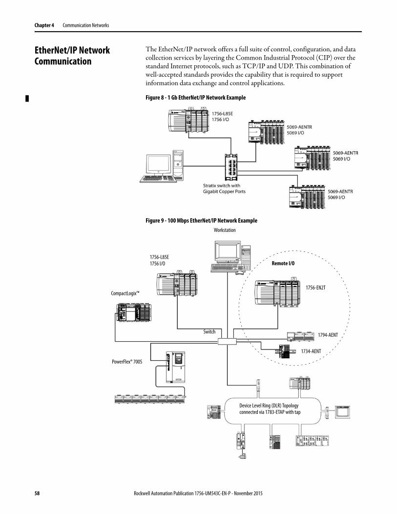
Chapter 4 Communication Networks
EtherNet/IP Network Communication
The EtherNet/IP network offers a full suite of control, configuration, and data collection services by layering the Common Industrial Protocol (CIP) over the standard Internet protocols, such as TCP/IP and UDP. This combination of well-accepted standards provides the capability that is required to support information data exchange and control applications.
Figure 8 - 1 Gb EtherNet/IP Network Example
Figure 9 - 100 Mbps EtherNet/IP Network Example
1756-L85E1756 I/O
CompactLogix™
PowerFlex® 700S
Switch 1794-AENT
1756-EN2T
Remote I/O
1734-AENT
Workstation
Device Level Ring (DLR) Topology connected via 1783-ETAP with tap
58 Rockwell Automation Publication 1756-UM543C-EN-P - November 2015

Communication Networks Chapter 4
For more information about using EtherNet/IP modules, see these publications:• EtherNet/IP Modules in Logix5000™ Control Systems User Manual,
publication ENET-UM001• EtherNet/IP Communication Modules in 5000 Series Systems,
publication ENET-UM004
ControlLogix EtherNet/IP Network Features
The ControlLogix EtherNet/IP network provides these features:• Support for messaging, produced/consumed tags, HMI, and
distributed I/O.• The ability to encapsulate messages within the standard TCP/UDP/IP
protocol.• A common application layer with ControlNet and DeviceNet networks• Network connections via RJ45 cable, or fiber optic links.• Compatible with industry-standard Ethernet switches (managed switches
are recommended, and CIP-protocol-aware switches can provide more predictable performance).
• Some devices include dual link ports that can provide media redundancy.• Support for Time Synchronization using the IEEE-1588 Precision Time
Protocol.
ControlLogix EtherNet/IP Communication Modules
For EtherNet/IP network communication in a ControlLogix system, you have several modules to choose from. Table 5 lists modules and their primary features.
Table 5 - EtherNet/IP Communication Modules
Module Is used to
1756-L83E, 1756-L85E
• Directly connect the controller to an EtherNet/IP network without requiring a bridge module.• Connect the controller with I/O modules.• Communicate to other EtherNet/IP devices (messages, produced/consumed tags).• Bridge messages between EtherNet/IP and modules in the ControlLogix chassis.• Support 10/100/1000 Mbps link speeds.
1756-ENBT • Connect controllers to I/O modules (requires an adapter for distributed I/O).• Communicate with other EtherNet/IP devices (messages).• Serve as a pathway to share data between Logix5000 controllers (produce/consume).• Bridge EtherNet/IP nodes to route messages to devices on other networks.
1756-EN2T • Perform the same functions as a 1756-ENBT module, with twice the capacity for more demanding applications.
• Provide a temporary configuration connection via the USB port.• Configure IP addresses quickly by using rotary switches.
1756-EN2F • Perform the same functions as a 1756-EN2T module.• Connect fiber media by an LC fiber connector on the module.
1756-EN2TR • Perform the same functions as a 1756-EN2T module.• Support communication on a ring topology for a Device Level Ring (DLR) single-fault tolerant ring
network.
Rockwell Automation Publication 1756-UM543C-EN-P - November 2015 59
Chapter 4 Communication Networks
Software for EtherNet/IP Networks
Table 6 lists software that is used with the EtherNet/IP networks and modules..
1756-EN2TRXT • Perform the same functions as a 1756-EN2T module.• Support communication on a ring topology for a Device Level Ring (DLR) single-fault tolerant ring
network.• Operate in extreme environments with -25…70 °C (-13…158 °F) temperatures.
1756-EN3TR • Perform the same functions as the 1756-EN2TR module.• Extended Integrated Motion on EtherNet/IP network.• Support of up to 128 motion axes.
1756-EN2TSC • Perform the same functions as a 1756-ENBT module, with twice the capacity for more demanding applications.
• Provide a temporary configuration connection via the USB port.• Configure IP addresses quickly by using rotary switches.
1756-EN2TXT • Perform the same functions as a 1756-EN2T module.• Operate in extreme environments with -25…70 °C (-13…158 °F) temperatures.
1756-EWEB • Provide customizable web pages for external access to controller information.• Provide remote access via an Internet browser to tags in a local ControlLogix controller.• Communicate with other EtherNet/IP devices (messages).• Bridge EtherNet/IP nodes to route messages to devices on other networks.• Support Ethernet devices that are not EtherNet/IP-based with a socket interface.This module does not provide support for I/O or produced/consumed tags.
Table 6 - Software for Use with EtherNet/IP Networks
Software Is used to Required or Optional
Logix Designer application • Configure ControlLogix projects.• Define EtherNet/IP communication.
Required
RSLinx® Classic or RSLinx® Enterprise
• Configure communication devices.• Provide diagnostics.• Establish communication between devices.
Required
BOOTP/DHCP Utility Assign IP addresses to the controller and devices on an EtherNet/IP network.
Optional
RSNetWorx™ for EtherNet/IP • Configure EtherNet/IP devices by IP addresses and/or host names.
• Provide bandwidth status.
Table 5 - EtherNet/IP Communication Modules (Continued)
Module Is used to
60 Rockwell Automation Publication 1756-UM543C-EN-P - November 2015
Communication Networks Chapter 4
Double Data Rate (DDR) Backplane Communication
The ControlLogix 5580 controller provides double data rate capabilities across the ControlLogix backplane.
The following communication modules support DDR when used with the ControlLogix 5580 controller. Minimum series are indicated as follows:
• 1756-EN2T/C• 1756-EN2TR/B• 1756-EN2TF/B• 1756-EN2TXT/C• 1756-EN3TR/A
For efficient DDR communication, make sure that all modules in the communication path are DDR modules.
If the chassis has a mix of DDR and non-DDR modules, then the DDR communication occurs between the modules that support it. Communication between the non-DDR modules in the chassis occurs at the non-DDR rate.
When multicast communication is used within a chassis that has a mix of DDR and non-DDR modules, then the transmission rate is limited to the slowest module—or at the non-DDR rate.
ControlNet Network Communication
The ControlNet network is a real-time control network that provides high-speed transport of time-critical I/O and interlocking data and messaging data. This includes the upload and download of program and configuration data on one physical-media link.
The ControlNet network is highly deterministic and repeatable and is unaffected when devices are connected or disconnected from the network. This quality results in dependable, synchronized, and coordinated real-time performance.
The ControlNet network often functions as the following:• A substitute/replacement for the remote I/O (RIO) network because the
ControlNet network adeptly handles large numbers of I/O points• A backbone for multiple distributed DeviceNet networks• A peer interlocking network
Rockwell Automation Publication 1756-UM543C-EN-P - November 2015 61

Chapter 4 Communication Networks
Figure 10 - ControlNet Network Overview
In this example, these actions occur via the ControlNet network:• The controllers produce and consume tags.• The controllers initiate MSG instructions that do the following:
– Send and receive data.– Configure devices.
• The workstation is used to do the following:– Configure the ControlNet devices and the ControlNet network.– Download and upload projects from the controllers.
For more information about using ControlNet modules, see ControlNet Modules in Logix5000 Control Systems User Manual, publication CNET-UM001.
ControlLogix ControlNet Module Features
The ControlNet communication modules provide these features:• Support for messaging, produced/consumed tags, and distributed I/O• Use a common application layer with DeviceNet and EtherNet/IP
networks• Requires no routing tables• Support the use of coax and fiber repeaters for isolation and increased
distance
OKFORCE SDRUN
Logix5585
LINK
NET
TM
SAFETY ON
0 0 0 0
DC INPUT AC OUTPUTDC INPUT
ControlNet
Distributed I/O
• 1756-L85E• 1756-CN2• 1756 I/O
• 1794-ACN15• 1794 I/O
Workstation
CompactLogix™
• 1734-ACNR• 1734 I/O
PanelView™
PowerFlex® 700S
62 Rockwell Automation Publication 1756-UM543C-EN-P - November 2015
Communication Networks Chapter 4
ControlLogix ControlNet Modules
Table 7 lists the available ControlLogix ControlNet modules and their primary features.
Software for ControlNet Networks
Table 8 lists software that is used with the ControlNet networks and modules.
Table 7 - ControlNet Modules and Capabilities
Module Is used to
1756-CNB • Control I/O modules.• Communicate with other ControlNet devices (messages).• Share data with other Logix5000 controllers (produce/consume).• Bridge ControlNet links to route messages to devices on other networks.
1756-CN2 • Perform the same functions as a 1756-CNB module.• Provide twice the capacity for more demanding applications.
1756-CN2R • Perform the same functions as a 1756-CN2 module.• Support redundant ControlNet media.
1756-CN2RXT • Perform same functions as a 1756-CN2R module.• Operate in extreme environments with -25…70 °C (-13…158 °F) temperatures.
1756-CNBR • Perform the same functions as a 1756-CNB module.• Support redundant ControlNet media.
Table 8 - Software for Use with ControlNet Networks
Software Is used to Required or Optional
Logix Designer application • Configure ControlLogix projects.• Define ControlNet communication.
Required
RSNetWorx™ for ControlNet™ • Configure ControlNet devices.• Schedule a network.
RSLinx Classic or Enterprise • Configure communication devices.• Provide diagnostics.• Establish communication between devices.
Rockwell Automation Publication 1756-UM543C-EN-P - November 2015 63
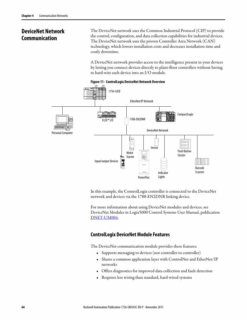
Chapter 4 Communication Networks
DeviceNet Network Communication
The DeviceNet network uses the Common Industrial Protocol (CIP) to provide the control, configuration, and data collection capabilities for industrial devices. The DeviceNet network uses the proven Controller Area Network (CAN) technology, which lowers installation costs and decreases installation time and costly downtime.
A DeviceNet network provides access to the intelligence present in your devices by letting you connect devices directly to plant-floor controllers without having to hard-wire each device into an I/O module.
Figure 11 - ControlLogix DeviceNet Network Overview
In this example, the ControlLogix controller is connected to the DeviceNet network and devices via the 1788-EN2DNR linking device.
For more information about using DeviceNet modules and devices, see DeviceNet Modules in Logix5000 Control Systems User Manual, publication DNET-UM004.
ControlLogix DeviceNet Module Features
The DeviceNet communication module provides these features:• Supports messaging to devices (not controller to controller)• Shares a common application layer with ControlNet and EtherNet/IP
networks• Offers diagnostics for improved data collection and fault detection• Requires less wiring than standard, hard-wired systems
OKFORCE SDRUN
Logix5585
LINK
NET
TM
SAFETY ON
0 0 0 0
DC INPUT AC OUTPUTDC INPUT
OKFORCE SDRUN
Logix5585
LINK
NET
TM
SAFETY ON
0 0 0 0
DC INPUT AC OUTPUTDC INPUT
1756-L85E
PowerFlex
Motor Starter
Input/output Devices
SensorPush Button Cluster
Barcode ScannerIndicator
Lights
DeviceNet Network
1788-EN2DNRCompactLogix
FLEX™ I/O
EtherNet/IP Network
Personal Computer
64 Rockwell Automation Publication 1756-UM543C-EN-P - November 2015
Communication Networks Chapter 4
ControlLogix DeviceNet Bridge Module and Linking Devices
Table 9 lists the available ControlLogix DeviceNet bridge and linking devices that can be used with the DeviceNet network.
Software for DeviceNet Networks
Table 10 lists software that is used with the DeviceNet networks and modules.
Connections Over DeviceNet Networks
The ControlLogix controller requires two connections for each 1756-DNB module. One connection is for module status and configuration. The other connection is a rack-optimized connection for the device data.
ControlLogix DeviceNet Module Memory
The 1756-DNB module has fixed sections of memory for the input and output data of the DeviceNet devices on the network. Each device on your network requires some input or output memory of the scanner. Some devices send and receive data, so they need input and output memory. The 1756-DNB module supports up to the following:
• 124 DINTs of input data• 123 DINTs of output data
Table 9 - DeviceNet Communication Modules and Capabilities
Module/Device Is used to
1756-DNB • Control I/O modules.• Communicate with other DeviceNet devices (via messages).
1788-EN2DNR Link an EtherNet/IP network to a DeviceNet network.
1788-CN2DN Link a ControlNet network to a DeviceNet network.
Table 10 - Software for Use with DeviceNet Networks
Software Is used to Required or Optional
Logix Designer application • Configure ControlLogix projects.• Define DeviceNet communication.
Required
RSNetWorx™ for DeviceNet • Configure DeviceNet devices.• Define the scan list for those devices.
RSLinx Classic or Enterprise • Configure communication devices.• Provide diagnostics.• Establish communication between devices.
Rockwell Automation Publication 1756-UM543C-EN-P - November 2015 65

Chapter 4 Communication Networks
Data Highway Plus (DH+) Network Communication
For DH+™ network communication, you have two module options for use in the ControlLogix chassis. Table 11 lists the DH+ modules and capabilities.
For DH+ network communication, use a 1756-DHRIO or 1756-DHRIOXT module in the ControlLogix chassis to exchange information between these controllers:
• PLC and SLC™ controllers• ControlLogix controllers and PLC or SLC controllers• ControlLogix controllers
The DH+ network also provides the following:• Data exchange between controllers• Plant-wide data sharing• Cellular level data sharing
You can connect a maximum of 32 stations to one DH+ link:• Channel A supports 57.6 Kbps, 115.2 Kbps, and 230.4 Kbps.• Channel B supports 57.6 Kbps and 115.2 Kbps.
Figure 12 - ControlLogix DH+ Network Communication Example
Table 11 - DH+ Modules and Capabilities
RIO Module Is used to
1756-DHRIO • Function as a remote I/O (RIO) scanner.• Support 32 logical rack connections or 16 block transfer connections per channel.• Establish connections between controllers and I/O adapters.• Distribute control so that each controller has its own I/O.
1756-DHRIOXT • Performs the same functions as a1756-DHRIO module.• Operates in extreme environments with -25…70 °C (-13…158 °F) temperatures.
SLC™ 500
DH+ Network
Data Collection and Recipe Management
PLC-5®
ControlLogix ControlLogix
DH+ Network
RSView® SLC 500PLC-5 RSView®
Workstation
EtherNet/IP Network
66 Rockwell Automation Publication 1756-UM543C-EN-P - November 2015
Communication Networks Chapter 4
Communicate Over a DH+ Network
For the controller to communicate to a workstation or other device over a DH+ network, use RSLinx Classic software to do the following:
• Specify a unique link ID for each ControlLogix backplane and additional network in the communication path.
• Configure the routing table for the 1756-DHRIO or 1756-DHRIOXT module.
The 1756-DHRIO or 1756-DHRIOXT module can route a message through up to four communication networks and three chassis. This limit applies only to the routing of a message and not to the total number of networks or chassis in a system.
For more information to configure and use a DH+ network via the 1756-DHRIO or 1756-DHRIOXT module, see the Data Highway Plus-Remote I/O Communication Interface Module User Manual, publication 1756-UM514.
Rockwell Automation Publication 1756-UM543C-EN-P - November 2015 67
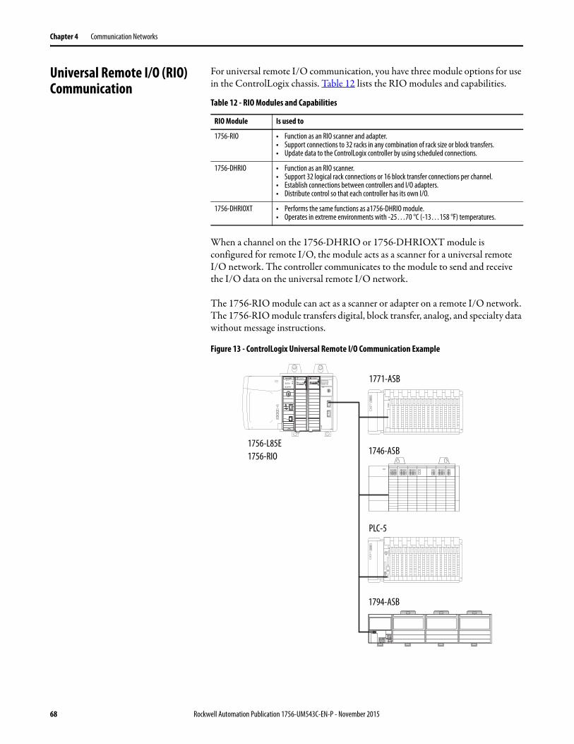
Chapter 4 Communication Networks
Universal Remote I/O (RIO) Communication
For universal remote I/O communication, you have three module options for use in the ControlLogix chassis. Table 12 lists the RIO modules and capabilities.
When a channel on the 1756-DHRIO or 1756-DHRIOXT module is configured for remote I/O, the module acts as a scanner for a universal remote I/O network. The controller communicates to the module to send and receive the I/O data on the universal remote I/O network.
The 1756-RIO module can act as a scanner or adapter on a remote I/O network. The 1756-RIO module transfers digital, block transfer, analog, and specialty data without message instructions.
Figure 13 - ControlLogix Universal Remote I/O Communication Example
Table 12 - RIO Modules and Capabilities
RIO Module Is used to
1756-RIO • Function as an RIO scanner and adapter.• Support connections to 32 racks in any combination of rack size or block transfers.• Update data to the ControlLogix controller by using scheduled connections.
1756-DHRIO • Function as an RIO scanner.• Support 32 logical rack connections or 16 block transfer connections per channel.• Establish connections between controllers and I/O adapters.• Distribute control so that each controller has its own I/O.
1756-DHRIOXT • Performs the same functions as a1756-DHRIO module.• Operates in extreme environments with -25…70 °C (-13…158 °F) temperatures.
OKFORCE SDRUN
Logix5585
LINK
NET
TM
SAFETY ON
0 0 0 0
DC INPUT DC INPUT
1756-L85E1756-RIO
1771-ASB
1746-ASB
PLC-5
1794-ASB
68 Rockwell Automation Publication 1756-UM543C-EN-P - November 2015

Communication Networks Chapter 4
Communicate Over a Universal Remote I/O NetworkFor the controller to control I/O over a universal remote I/O network, you must complete these tasks.
1. Configure the remote I/O adapter.2. Lay out the remote I/O network cable.3. Connect the remote I/O network cable.4. Configure the scanner channel.
For more information to configure a remote I/O network with the 1756-RIO, 1756-DHRIO, or 1756-DHRIOXT modules, see these publications:
• Data Highway Plus-Remote I/O Communication Interface Module User Manual, publication 1756-UM514
• ControlLogix Remote I/O Communication Module User Manual, publication 1756-UM534
As you design your remote I/O network, remember the following:• All devices that are connected to a remote I/O network must
communicate by using the same communication rate. These rates are available for remote I/O:– 57.6 Kbps– 115.2 Kbps– 230.4 Kbps
• You must assign unique partial and full racks to each channel used in Remote I/O Scanner mode.Both channels of a 1756-DHRIO or 1756-DHRIOXT module cannot scan the same partial or full rack address. Both module channels can communicate to 00…37 octal or 40…77 octal, but each channel can communicate only with one address at a time in whichever of these two ranges it falls.
Rockwell Automation Publication 1756-UM543C-EN-P - November 2015 69
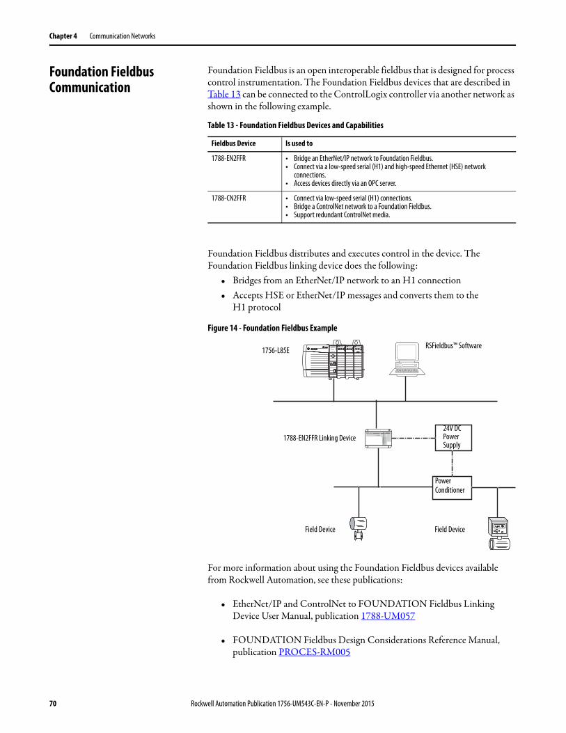
Chapter 4 Communication Networks
Foundation Fieldbus Communication
Foundation Fieldbus is an open interoperable fieldbus that is designed for process control instrumentation. The Foundation Fieldbus devices that are described in Table 13 can be connected to the ControlLogix controller via another network as shown in the following example.
Foundation Fieldbus distributes and executes control in the device. The Foundation Fieldbus linking device does the following:
• Bridges from an EtherNet/IP network to an H1 connection• Accepts HSE or EtherNet/IP messages and converts them to the
H1 protocol
Figure 14 - Foundation Fieldbus Example
For more information about using the Foundation Fieldbus devices available from Rockwell Automation, see these publications:
• EtherNet/IP and ControlNet to FOUNDATION Fieldbus Linking Device User Manual, publication 1788-UM057
• FOUNDATION Fieldbus Design Considerations Reference Manual, publication PROCES-RM005
Table 13 - Foundation Fieldbus Devices and Capabilities
Fieldbus Device Is used to
1788-EN2FFR • Bridge an EtherNet/IP network to Foundation Fieldbus.• Connect via a low-speed serial (H1) and high-speed Ethernet (HSE) network
connections.• Access devices directly via an OPC server.
1788-CN2FFR • Connect via low-speed serial (H1) connections.• Bridge a ControlNet network to a Foundation Fieldbus.• Support redundant ControlNet media.
OKFORCE SDRUN
Logix5585
LINK
NET
TM
SAFETY ON
0 0 0 0
DC INPUT AC OUTPUTDC INPUT RSFieldbus™ Software
24V DC Power Supply
Power Conditioner
Field Device Field Device
1788-EN2FFR Linking Device
1756-L85E
70 Rockwell Automation Publication 1756-UM543C-EN-P - November 2015
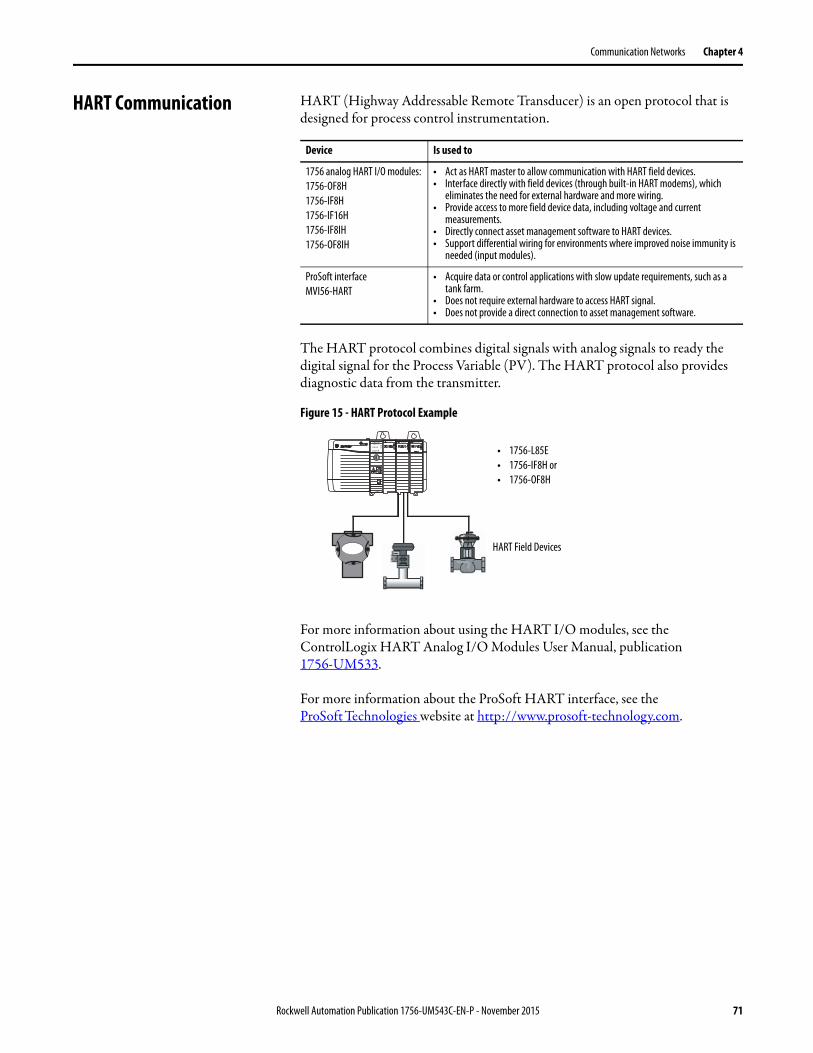
Communication Networks Chapter 4
HART Communication HART (Highway Addressable Remote Transducer) is an open protocol that is designed for process control instrumentation.
The HART protocol combines digital signals with analog signals to ready the digital signal for the Process Variable (PV). The HART protocol also provides diagnostic data from the transmitter.
Figure 15 - HART Protocol Example
For more information about using the HART I/O modules, see the ControlLogix HART Analog I/O Modules User Manual, publication 1756-UM533.
For more information about the ProSoft HART interface, see the ProSoft Technologies website at http://www.prosoft-technology.com.
Device Is used to
1756 analog HART I/O modules:1756-OF8H1756-IF8H 1756-IF16H 1756-IF8IH 1756-OF8IH
• Act as HART master to allow communication with HART field devices.• Interface directly with field devices (through built-in HART modems), which
eliminates the need for external hardware and more wiring.• Provide access to more field device data, including voltage and current
measurements.• Directly connect asset management software to HART devices.• Support differential wiring for environments where improved noise immunity is
needed (input modules).
ProSoft interfaceMVI56-HART
• Acquire data or control applications with slow update requirements, such as a tank farm.
• Does not require external hardware to access HART signal.• Does not provide a direct connection to asset management software.
OKFORCE SDRUN
Logix5585
LINK
NET
TM
SAFETY ON
0 0 0 0
DC INPUT AC OUTPUTDC INPUT
• 1756-L85E• 1756-IF8H or• 1756-OF8H
HART Field Devices
Rockwell Automation Publication 1756-UM543C-EN-P - November 2015 71

Chapter 4 Communication Networks
Notes:
72 Rockwell Automation Publication 1756-UM543C-EN-P - November 2015
Chapter 5
Manage Controller Communication
Connection Overview A Logix5000™ controller provides connection resources whenever communications are established between two devices.
Connections are used when the system contains the following conditions or activities:
• I/O modules, communication modules, and adapter modules are present in the I/O configuration of the user project.
• Produced or Consumed tags are configured in the user project.• Connected Messages are executed in the user application.• External devices, programming terminals, or HMIs communicate with the
controller.
Topic Page
Connection Overview 73
Nodes on an EtherNet/IP Network 74
Controller Communication Interaction with Control Data 75
Produce and Consume (Interlock) Data 77
Send and Receive Messages 78
Socket Interface 80
Rockwell Automation Publication 1756-UM543C-EN-P - November 2015 73
Chapter 5 Manage Controller Communication
Nodes on an EtherNet/IP Network
When configuring your ControlLogix® 5580 control system, you must account for the number of EtherNet/IP nodes you include in the I/O configuration tree in your project. Table 14 shows the maximum number of EtherNet/IP nodes supported for the ControlLogix 5580 controllers.
Devices Included in the Node Count
Any EtherNet/IP devices that you add directly to the I/O configuration are counted toward the node limits of the controller. The following are examples of devices that must be counted:
• Remote communication adapters• Devices with an embedded EtherNet/IP port, such as I/O modules, drives,
and linking devices• EtherNet/IP devices connected to a communication module in the local
chassis, even though the communication module in the local chassis does not count as a node. See Figure 16 on page 75.
• Remote controllers.• HMI devices that are included in the I/O configuration section, for
example, PanelView™ Plus terminals.• Third-party devices that are directly connected to the EtherNet/IP
network.
Devices Excluded from the Node Count
When considering the EtherNet/IP node limitation of a ControlLogix 5580 controller, you do not count Ethernet devices that exist on the EtherNet/IP network but are not added to the I/O configuration section of the project. The following devices are not added to the I/O configuration section in your project and are not counted among the total number of nodes:
• Computer• Communication modules in the local chassis.• HMIs that are not added to the I/O configuration section.• MSG Instructions• Standard Ethernet devices that the controllers use a socket interface to
communicate with.
Table 14 - ControlLogix 5580 Controller EtherNet/IP Node Guidelines
Cat. No. Maximum Number of Ethernet/IP Nodes Supported
1756-L83E 100
1756-L85E 300
IMPORTANT EtherNet/IP communication modules in the local chassis with the controller do not count as nodes, but EtherNet/IP devices connected to the communication modules do count as nodes. See Figure 16 on page 75.
74 Rockwell Automation Publication 1756-UM543C-EN-P - November 2015
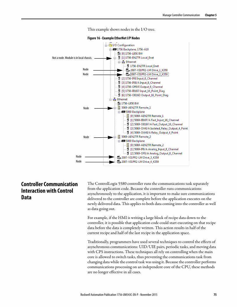
Manage Controller Communication Chapter 5
This example shows nodes in the I/O tree.
Figure 16 - Example EtherNet I/P Nodes
Controller Communication Interaction with Control Data
The ControlLogix 5580 controller runs the communications task separately from the application code. Because the controller runs communications asynchronously to the application, it is important to make sure communications delivered to the controller are complete before the application executes on the newly delivered data. This applies to both data coming into the controller as well as data going out.
For example, if the HMI is writing a large block of recipe data down to the controller, it is possible that application code could start executing on that recipe data before the data is completely written. This action results in half of the current recipe and half of the last recipe in the application space.
Traditionally, programmers have used several techniques to control the effects of asynchronous communications: UID/UIE pairs, periodic tasks, and moving data with CPS instructions. These techniques all rely on controlling when the main core is allowed to switch tasks, thus preventing the communications task from changing data while the control task was using it. Because the controller performs communications processing on an independent core of the CPU, these methods are no longer effective in all cases.
Node
Node
Node
Not a node. Module is in local chassis.
Node
NodeNode
Rockwell Automation Publication 1756-UM543C-EN-P - November 2015 75
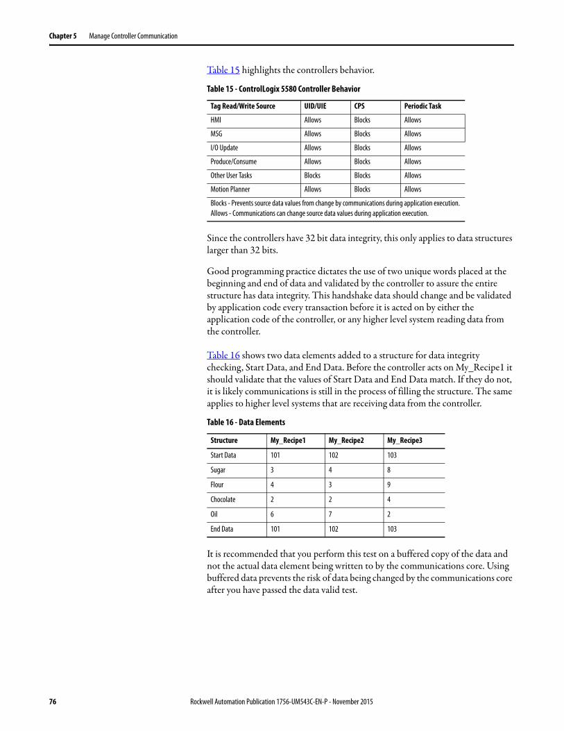
Chapter 5 Manage Controller Communication
Table 15 highlights the controllers behavior.
Since the controllers have 32 bit data integrity, this only applies to data structures larger than 32 bits.
Good programming practice dictates the use of two unique words placed at the beginning and end of data and validated by the controller to assure the entire structure has data integrity. This handshake data should change and be validated by application code every transaction before it is acted on by either the application code of the controller, or any higher level system reading data from the controller.
Table 16 shows two data elements added to a structure for data integrity checking, Start Data, and End Data. Before the controller acts on My_Recipe1 it should validate that the values of Start Data and End Data match. If they do not, it is likely communications is still in the process of filling the structure. The same applies to higher level systems that are receiving data from the controller.
It is recommended that you perform this test on a buffered copy of the data and not the actual data element being written to by the communications core. Using buffered data prevents the risk of data being changed by the communications core after you have passed the data valid test.
Table 15 - ControlLogix 5580 Controller Behavior
Tag Read/Write Source UID/UIE CPS Periodic Task
HMI Allows Blocks Allows
MSG Allows Blocks Allows
I/O Update Allows Blocks Allows
Produce/Consume Allows Blocks Allows
Other User Tasks Blocks Blocks Allows
Motion Planner Allows Blocks Allows
Blocks - Prevents source data values from change by communications during application execution. Allows - Communications can change source data values during application execution.
Table 16 - Data Elements
Structure My_Recipe1 My_Recipe2 My_Recipe3
Start Data 101 102 103
Sugar 3 4 8
Flour 4 3 9
Chocolate 2 2 4
Oil 6 7 2
End Data 101 102 103
76 Rockwell Automation Publication 1756-UM543C-EN-P - November 2015

Manage Controller Communication Chapter 5
Produce and Consume (Interlock) Data
ControlLogix controllers let you produce (transmit) and consume (receive) controller-scoped tags. ControlLogix 5580 controllers produce the same standard tag through both the Ethernet port and the backplane, and consumer counts apply to the total consumers from both ports.
Figure 17 - Illustration of Produced and Consumed Tags
The system-shared tags are explained in Table 17.
For two controllers to share produced or consumed tags, the controllers must be attached to the same network. You cannot bridge produced and consumed tags over two networks.
Produced and consumed tags use connections of the controller and the communication modules being used.
Table 17 - Produced and Consumed Tag Definitions
Tag Definition
Produced tag A tag that a controller makes available for use by other controllers. Multiple controllers can simultaneously consume (receive) the data. A produced tag sends its data to one or more consumed tags (consumers) without using logic.
Consumed tag A tag that receives the data of a produced tag. The data type of the consumed tag must match the data type (including any array dimensions) of the produced tag. The RPI of the consumed tag determines the period at which the data updates.
Controller_2
Controller_3
Controller_4
Consumed Tag
Consumed Tag
Consumed Tag
Controller_1
Produced Tag
Rockwell Automation Publication 1756-UM543C-EN-P - November 2015 77
Chapter 5 Manage Controller Communication
For a ControlNet network, produced and consumed tags use scheduled connections.
Requested Packet Interval (RPI) of Multicast Tags
The first consumer of a multicast produced tag on any given communications port establishes the RPI value for that port. All subsequent consumers using the same port must request the same RPI value as the first consumer, otherwise they will fail to connect. Controllers with backplane and EtherNet/IP ports can produce data at an independent RPI value on each port.
For more information about produced/consumed tags, see the Logix5000™ Controllers Produced and Consumed Tags Programming Manual, publication 1756-PM011.
Send and Receive Messages Messages transfer data to other devices, such as other controllers or operator interfaces. The MSG instruction is a ladder logic output instruction that asynchronously reads or writes a block of data to or from another module over the backplane or a network. The size of the instruction depends on the data types and message command that you program.
Messages use connection resources to send or receive data. Messages can leave the connection open (cached) or can close the connection when the message is done transmitting.
Messages can be either unconnected or connected. Unconnected messages are dependent upon the availability of unconnected buffers in all of the devices through which the message passes. Connected messages begin with a request to allocate connection buffers in all of those devices, before sending the actual message. Choosing to cache a connected message instructs the controller to keep the connection open after the message has been completed - this improves efficiency if the message is intended to be sent repeatedly.
Table 18 - ControlNet Connections
Connection Definition
Scheduled(unique to a ControlNet network)
A scheduled connection is unique to ControlNet communication. A scheduled connection lets you send and receive data repeatedly at a predetermined interval, which is the requested packet interval (RPI). For example, a connection to an I/O module is a scheduled connection because you repeatedly receive data from the module at a specified interval.Other scheduled connections include connections to the following:• Communication devices• Produced/consumed tagsOn a ControlNet network, you must use RSNetWorx™ for ControlNet software to enable all scheduled connections and establish a network update time (NUT). A scheduled connection reserves network bandwidth specifically to handle the connection.
Unscheduled An unscheduled connection is a message transfer between devices that the requested packet interval (RPI) or the program, such as a MSG instruction, triggers. Unscheduled messaging lets you send and receive data as you need.Unscheduled connections use the remainder of network bandwidth after scheduled connections are allocated.
78 Rockwell Automation Publication 1756-UM543C-EN-P - November 2015
Manage Controller Communication Chapter 5
Connected messages use connection resources. If the connected message is uncached, the resources are used temporarily each time the message is triggered. As long as a cached connected message remains in the cache, the resources remain allocated and are not available for other messages. Messages can get pushed from the cache if the application exceeds the cache capacity of the controller.
Each message uses one connection out of the controller, regardless of how many devices are in the message path.
For more information about using messages, see these publications:• Logix5000 Controllers Messages Programming Manual,
publication 1756-PM012
Determine Whether to Cache Message Connections
When you configure a MSG instruction, you can choose whether to cache the connection. Use Table 20 to determine options for caching connections.
Table 19 - Message Types
Message Type Communication Method
Connected Message Message Can Be Cached
CIP data table read or write N/A Configurable Yes(2)
PLC-2®, PLC-3®, PLC-5®, or SLC™ (all types)
CIP No No
CIP with Source ID No No
DH+™ Yes Yes(2)
CIP generic N/A Optional (1)
(1) You can connect CIP generic messages. However, for most applications we recommend that you leave CIP generic messages unconnected.
Yes(2)
(2) Connected messages that occur more frequently than once every 60 seconds should be cached if possible.
Block-transfer read or write N/A Yes Yes(2)
Table 20 - Options for Caching Connections
If the message executes Then
Repeatedly Cache the connection.This keeps the connection open and optimizes execution time. Opening a connection each time the message executes increases execution time.
Infrequently Do not cache the connection.This closes the connection upon completion of the message, which frees up that connection for other uses.
TIP Cached connections transfer data faster than uncached connections. The ControlLogix 5580 controller can cache 256 messages and trigger 256 messages simultaneously.
Rockwell Automation Publication 1756-UM543C-EN-P - November 2015 79

Chapter 5 Manage Controller Communication
Socket Interface The controller can use socket interfaces to communicate with Ethernet devices that do not support the EtherNet/IP application protocol. The socket interface is implemented via the Socket Object. The controller communicates with the Socket Object via MSG instructions. MSG instructions that configure and operate the socket interface must be configured as Unconnected, and use the Message to Self path. To communicate with another device, you must understand the application protocol of the other device.
The ControlLogix 5580 controllers support up to 32 socket instances on a per-module basis; 32 sockets for the embedded Ethernet port, plus 32 more for each Ethernet bridge module in the local chassis.
For more information on the socket interface, see EtherNet/IP Socket Interface Application Technique, publication ENET-AT002.
80 Rockwell Automation Publication 1756-UM543C-EN-P - November 2015
Chapter 6
I/O Modules
Selecting ControlLogix I/O Modules
Rockwell Automation offers many I/O modules for use in ControlLogix® 5580 controller systems. For a list of all I/O product lines that are compatible with the ControlLogix 5580 controllers, see the 1756 ControlLogix Controllers Technical Data, publication 1756-TD001.
When you select I/O modules, remember the following:
• A wide variety of digital, analog, and specialty I/O modules are available from Rockwell Automation. A number of these I/O modules support the following features:– Field-side diagnostics– Electronic fusing– Individually isolated inputs/outputs– Timestamping of inputs– Scheduling of outputs– Event detection of specific input patterns
• Removable terminal blocks (RTBs) or 1492 wiring systems are required for use with I/O modules, and you may have to order these separately.
• 1492 PanelConnect™ modules and cables can be used to connect input modules to sensors.
Topic Page
Selecting ControlLogix I/O Modules 81
Local I/O Modules 83
Remote I/O Modules 85
Add to the I/O Configuration While Online 92
Determine When Data is Updated 93
Rockwell Automation Publication 1756-UM543C-EN-P - November 2015 81
Chapter 6 I/O Modules
Electronic Keying
Electronic Keying reduces the possibility that you use the wrong device in a control system. It compares the device that is defined in your project to the installed device. If keying fails, a fault occurs. These attributes are compared.
The following Electronic Keying options are available.
Carefully consider the implications of each keying option when selecting one.
More Information
For more detailed information on Electronic Keying, see Electronic Keying in Logix5000™ Control Systems Application Technique, publication LOGIX-AT001.
Attribute Description
Vendor The device manufacturer.
Device Type The general type of the product, for example, digital I/O module.
Product Code The specific type of the product. The Product Code maps to a catalog number.
Major Revision A number that represents the functional capabilities of a device.
Minor Revision A number that represents behavior changes in the device.
Keying Option Description
Compatible Module
Lets the installed device accept the key of the device that is defined in the project when the installed device can emulate the defined device. With Compatible Module, you can typically replace a device with another device that has the following characteristics: • Same catalog number• Same or higher Major Revision• Minor Revision as follows:
– If the Major Revision is the same, the Minor Revision must be the same or higher.– If the Major Revision is higher, the Minor Revision can be any number.
Disable Keying Indicates that the keying attributes are not considered when attempting to communicate with a device. With Disable Keying, communication can occur with a device other than the type specified in the project.ATTENTION: Be cautious when using Disable Keying; if used incorrectly, this option can lead to personal injury or death, property damage, or economic loss. We strongly recommend that you do not use Disable Keying. If you use Disable Keying, you must take full responsibility for understanding whether the device being used can fulfill the functional requirements of the application.
Exact Match Indicates that all keying attributes must match to establish communication. If any attribute does not match precisely, communication with the device does not occur.
IMPORTANT When you change Electronic Keying parameters online, it interrupts connections to the device and any devices that are connected through the device. Connections from other controllers can also be broken.
If an I/O connection to a device is interrupted, the result can be a loss of data.
82 Rockwell Automation Publication 1756-UM543C-EN-P - November 2015

I/O Modules Chapter 6
Local I/O Modules The ControlLogix chassis that you choose affects how many local I/O modules you can use. Several ControlLogix chassis sizes are available to suit your configuration requirements. You can fill the slots of your chassis with any combination of controllers, communication modules, and I/O modules.
Table 21 lists the available ControlLogix chassis and the number of slots available with each.
If you have empty slots in your chassis, use the 1756-N2 or 1756-N2XT slot-filler module.
Add Local I/O to the I/O Configuration
If you are adding local I/O, add the I/O module to the backplane with the controller. To add an I/O module to the local chassis, complete these steps.
1. Right-click the backplane and choose New Module.
Table 21 - ControlLogix and ControlLogix- Chassis and Slots
Chassis Slots
1756-A4 4
1756-A4LXT
1756-A5XT 5
1756-A7 7
1756-A7LXT
1756-A7XT
1756-A10 10
1756-A13 13
1756-A17 17
Rockwell Automation Publication 1756-UM543C-EN-P - November 2015 83
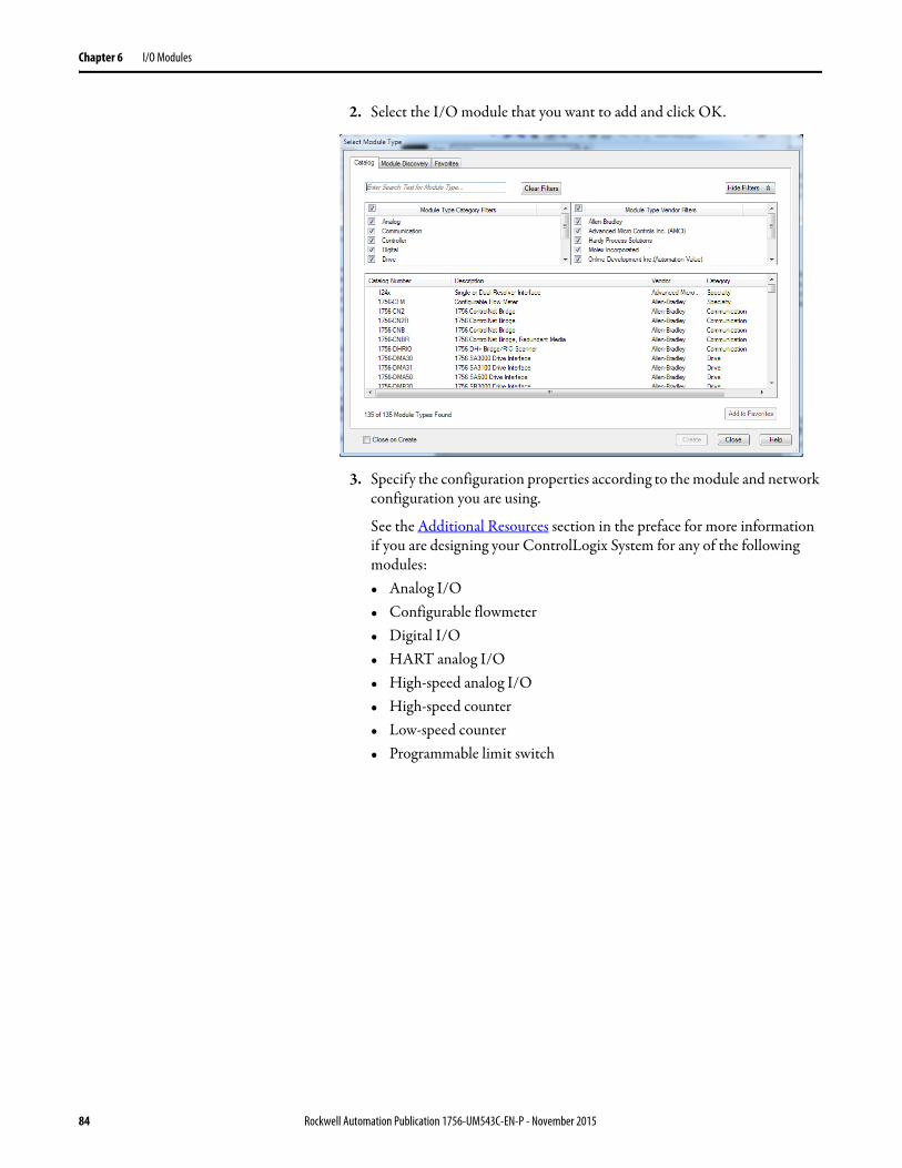
Chapter 6 I/O Modules
2. Select the I/O module that you want to add and click OK.
3. Specify the configuration properties according to the module and network configuration you are using.
See the Additional Resources section in the preface for more information if you are designing your ControlLogix System for any of the following modules:• Analog I/O• Configurable flowmeter• Digital I/O• HART analog I/O• High-speed analog I/O• High-speed counter• Low-speed counter• Programmable limit switch
84 Rockwell Automation Publication 1756-UM543C-EN-P - November 2015
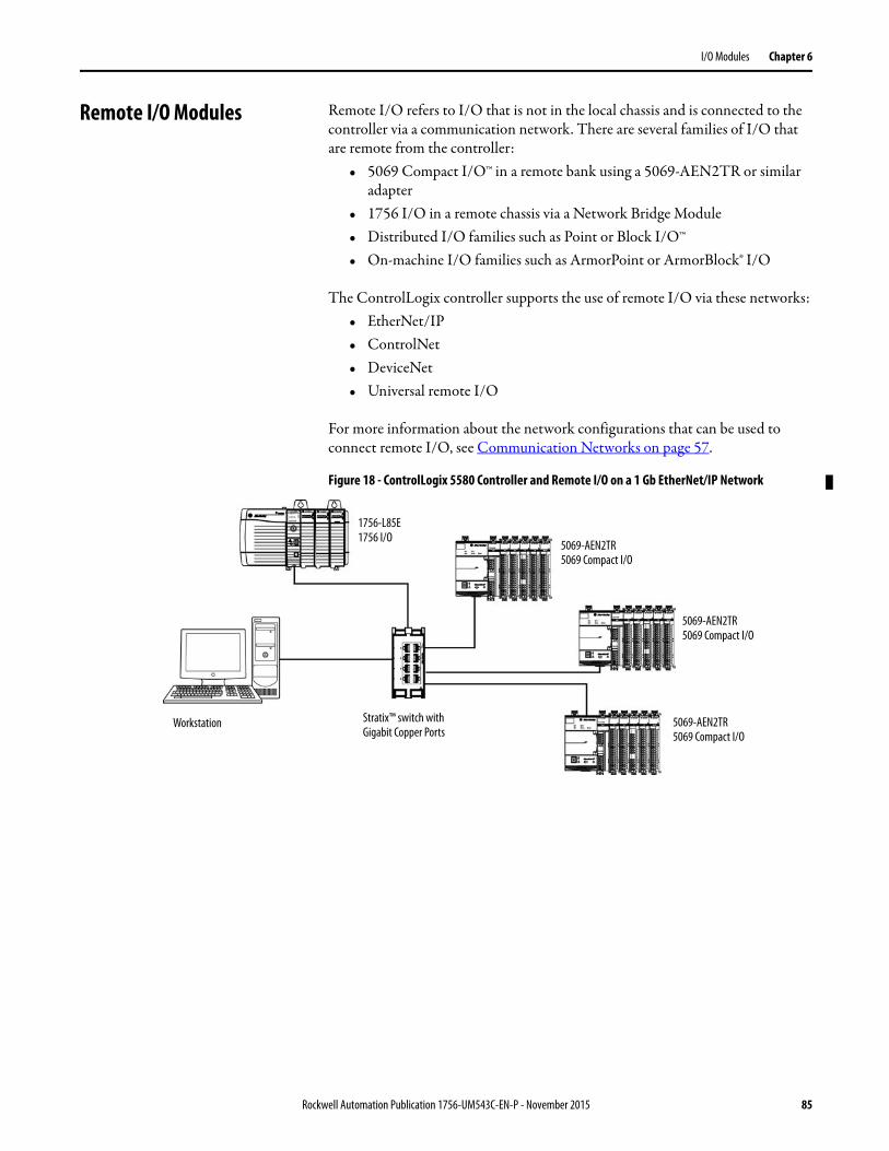
I/O Modules Chapter 6
Remote I/O Modules Remote I/O refers to I/O that is not in the local chassis and is connected to the controller via a communication network. There are several families of I/O that are remote from the controller:
• 5069 Compact I/O™ in a remote bank using a 5069-AEN2TR or similar adapter
• 1756 I/O in a remote chassis via a Network Bridge Module• Distributed I/O families such as Point or Block I/O™• On-machine I/O families such as ArmorPoint or ArmorBlock® I/O
The ControlLogix controller supports the use of remote I/O via these networks:• EtherNet/IP• ControlNet• DeviceNet• Universal remote I/O
For more information about the network configurations that can be used to connect remote I/O, see Communication Networks on page 57.
Figure 18 - ControlLogix 5580 Controller and Remote I/O on a 1 Gb EtherNet/IP Network
1756-L85E1756 I/O
5069-AEN2TR5069 Compact I/O
5069-AEN2TR5069 Compact I/O
5069-AEN2TR5069 Compact I/O
Stratix™ switch with Gigabit Copper Ports
Workstation
Rockwell Automation Publication 1756-UM543C-EN-P - November 2015 85
Chapter 6 I/O Modules
Add Remote I/O to the Ethernet Port on the Controller
If you are adding remote I/O, you can add the I/O modules to the Ethernet port of the controller. To add remote I/O to the I/O Configuration folder in the Logix Designer application, complete these steps.
1. In the I/O Configuration tree, right-click Ethernet and choose New Module.
2. Select the remote communication module or EtherNet/IP device.
For some modules, the Select Major Revision dialog box can appear. If the dialog box appears, choose the major revision of the module and click OK.
3. Make sure Close on Create is checked.
4. Click Create.
5. Specify the communication module properties according to your network configuration.
For more information about the communication module and network properties, see the Additional Resources section in the Preface.
86 Rockwell Automation Publication 1756-UM543C-EN-P - November 2015

I/O Modules Chapter 6
6. Right-click the backplane of the newly added communication module and choose New Module.
7. Select the I/O module that you want to add and click OK.
8. Make sure Close on Create is checked.
9. Click Create.
10. Specify the Module Properties according to your module and application.
See the Additional Resources section in the Preface for more information about the module configuration properties for any of the following modules:• Analog I/O• Configurable flowmeter• Digital I/O• HART analog I/O• High-speed analog I/O• High-speed counter• Low-speed counter• Programmable limit switch
Rockwell Automation Publication 1756-UM543C-EN-P - November 2015 87

Chapter 6 I/O Modules
11. Add any other I/O modules that you are using in the remote chassis.
12. Complete steps 1…11 until your remote I/O network and I/O modules are configured.
Add Remote I/0 to a Local Communication Module
If you are using local communication modules that are connected to the controller, then add the I/O modules to the backplane of the communication module. To add remote I/O to the I/O Configuration tree in the Logix Designer application, complete these steps.
1. Right-click the backplane of the local chassis, and choose New Module.
2. Select a communication module.
3. Click Create.
88 Rockwell Automation Publication 1756-UM543C-EN-P - November 2015
I/O Modules Chapter 6
4. Specify the communication module properties according to your network configuration.
For more information about the communication module and network properties, see the Additional Resources section in the Preface.
5. Click OK.
6. Click Close on the Select Module Type dialog box.
7. Right-click the communication network under the communication module, and choose New Module.
Rockwell Automation Publication 1756-UM543C-EN-P - November 2015 89
Chapter 6 I/O Modules
8. Select the communication adapter for the I/O platform that you are using.
9. Click Create.
10. Specify the module and connection properties according to your network configuration.
11. Click OK.
12. Click Close on the Select Module Type dialog box.
90 Rockwell Automation Publication 1756-UM543C-EN-P - November 2015
I/O Modules Chapter 6
13. Right-click the backplane of the newly added communication adapter and choose New Module.
14. Select the I/O module that you want to add and click Create.
15. Specify the Module Properties according to your module and application.
For more information about the module configuration properties, see the user manual for the I/O module you are adding.
16. Add any other I/O modules that you are using in this bus.
17. Complete steps 1…16 until your remote I/O network and I/O modules are configured.
Rockwell Automation Publication 1756-UM543C-EN-P - November 2015 91
Chapter 6 I/O Modules
Add to the I/O Configuration While Online
With Studio 5000® software, version 28 or later, you can add I/O and other devices to the controller configuration while you are online, and the mode switch is in either the REM or PROG positions.
The modules and devices you can add while online depends on the version of the software you are using. Later versions have more modules and devices that can be added while online.
You can add modules and devices to the local or remote chassis via an EtherNet/IP network, or via the unscheduled portion of a ControlNet network.
For information on the number of nodes you can have for an EtherNet/IP network, see Nodes on an EtherNet/IP Network on page 74.
For more information about adding to the I/O Configuration while online, see the these publications:
• Runtime/On-line Addition of ControlLogix (1756) I/O over ControlNet and EtherNet/IP White Paper, publication LOGIX-WP006
• Logix5000 Controllers Design Considerations Reference Manual, publication 1756-RM094
Modules and Devices that Can be Added While Online
You can add these modules and devices to the ControlLogix 5580 controller I/O configuration while online with Logix Designer, version 28.00.00 or later.
• 1756 controllers• 1756 ControlNet modules• 1756 DeviceNet bridges• 1756 EtherNet/IP modules• 5069 EtherNet/IP adapters• 5069 Compact I/O™ modules• 1756 I/O and specialty modules• 1756-DHRIO• 1756-DHRIOXT
IMPORTANT These ControlLogix modules cannot be added while online:• 1756-RIO• 1756-SYNCH
92 Rockwell Automation Publication 1756-UM543C-EN-P - November 2015
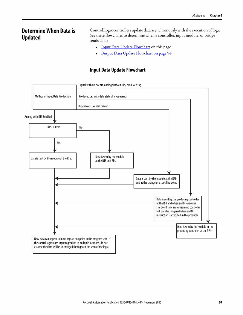
I/O Modules Chapter 6
Determine When Data is Updated
ControlLogix controllers update data asynchronously with the execution of logic. See these flowcharts to determine when a controller, input module, or bridge sends data:
• Input Data Update Flowchart on this page• Output Data Update Flowchart on page 94
Input Data Update Flowchart
Method of Input Data Production
Digital without events, analog without RTS, produced tag
Produced tag with data state change events
Digital with Events Enabled
Analog with RTS Enabled
RTS RPI?
Yes
No
Data is sent by the module at the RTS. Data is sent by the module at the RTS and RPI.
New data can appear in Input tags at any point in the program scan. If the control logic reads input tag values in multiple locations, do not assume the data will be unchanged throughout the scan of the logic.
Data is sent by the module or the producing controller at the RPI.
Data is sent by the producing controller at the RPI and when an IOT executes. The Event task in a consuming controller will only be triggered when an IOT instruction is executed in the producer.
Data is sent by the module at the RPI and at the change of a specified point.
Rockwell Automation Publication 1756-UM543C-EN-P - November 2015 93
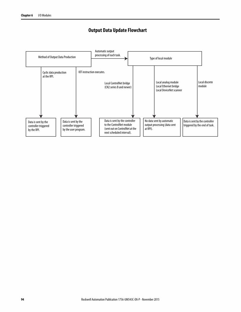
Chapter 6 I/O Modules
Output Data Update Flowchart
Method of Output Data Production
Automatic output processing of each task.
Type of local module
Local analog moduleLocal Ethernet bridgeLocal DeviceNet scanner
Data is sent by the controller triggered by the RPI.
Data is sent by the controller triggered by the user program.
Data is sent by the controller to the ControlNet module (sent out on ControlNet at the next scheduled interval).
Local discrete module
Local ControlNet bridge (CN2 series B and newer)
No data sent by automatic output processing (data sent at RPI).
Data is sent by the controller triggered by the end of task.
IOT instruction executes.Cyclic data production at the RPI.
94 Rockwell Automation Publication 1756-UM543C-EN-P - November 2015
Chapter 7
Develop Applications
Elements of a Control Application
A control application consists of several elements that require planning for efficient application execution. Application elements include the following:
• Tasks• Programs• Routines• Parameters and Local Tags• Add-On Instructions
Topic Page
Elements of a Control Application 95
Tasks 96
Programs 99
Routines 102
Parameters and Local Tags 103
Programming Languages 104
Add-On Instructions 105
Extended Properties 106
Access the Module Object from an Add-On Instruction 107
Monitoring Controller Status 108
Monitoring I/O Connections 108
Rockwell Automation Publication 1756-UM543C-EN-P - November 2015 95
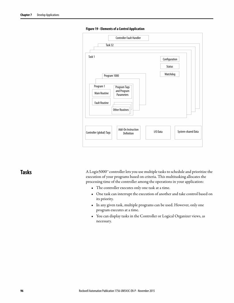
Chapter 7 Develop Applications
Figure 19 - Elements of a Control Application
Tasks A Logix5000™ controller lets you use multiple tasks to schedule and prioritize the execution of your programs based on criteria. This multitasking allocates the processing time of the controller among the operations in your application:
• The controller executes only one task at a time.• One task can interrupt the execution of another and take control based on
its priority.• In any given task, multiple programs can be used. However, only one
program executes at a time.• You can display tasks in the Controller or Logical Organizer views, as
necessary.
Task 32
Task 1Configuration
Status
WatchdogProgram 1000
Program 1
Main Routine
Fault Routine
Program Tags and Program Parameters
Other Routines
I/O Data System-shared Data
Controller Fault Handler
Controller (global) TagsAdd-On Instruction
Definition
96 Rockwell Automation Publication 1756-UM543C-EN-P - November 2015

Develop Applications Chapter 7
Figure 20 - Task Within a Control Application
Figure 21 - Tasks
Task 32
Task 1 Configuration
Status
WatchdogProgram 1000
Program 1
Main Routine
Fault Routine
Other Routines
Controller (global) Tags
I/O Data System-shared Data
Controller Fault Handler
Program Tags and Program Parameters
Add-On Instruction Definition
Main Task (continuous)
Task 2(periodic)
Main Task (continuous)
Task 2(periodic)
Controller Organizer Logical Organizer
Rockwell Automation Publication 1756-UM543C-EN-P - November 2015 97
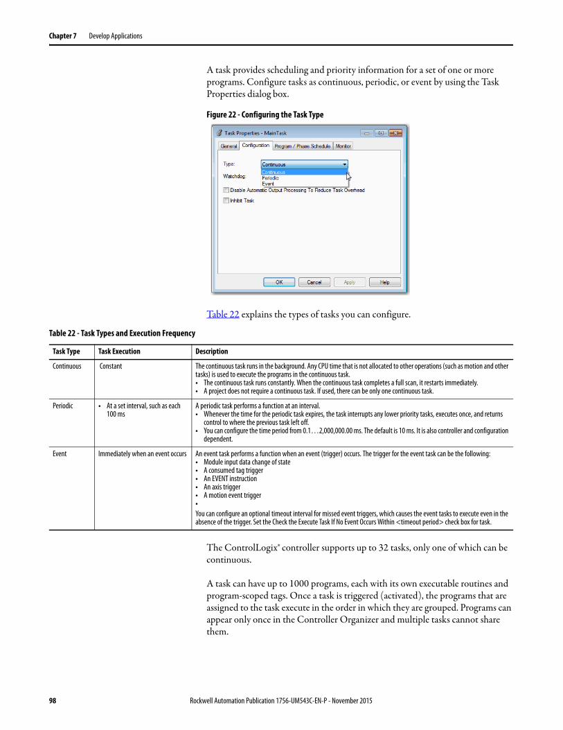
Chapter 7 Develop Applications
A task provides scheduling and priority information for a set of one or more programs. Configure tasks as continuous, periodic, or event by using the Task Properties dialog box.
Figure 22 - Configuring the Task Type
Table 22 explains the types of tasks you can configure.
The ControlLogix® controller supports up to 32 tasks, only one of which can be continuous.
A task can have up to 1000 programs, each with its own executable routines and program-scoped tags. Once a task is triggered (activated), the programs that are assigned to the task execute in the order in which they are grouped. Programs can appear only once in the Controller Organizer and multiple tasks cannot share them.
Table 22 - Task Types and Execution Frequency
Task Type Task Execution Description
Continuous Constant The continuous task runs in the background. Any CPU time that is not allocated to other operations (such as motion and other tasks) is used to execute the programs in the continuous task.• The continuous task runs constantly. When the continuous task completes a full scan, it restarts immediately.• A project does not require a continuous task. If used, there can be only one continuous task.
Periodic • At a set interval, such as each 100 ms
A periodic task performs a function at an interval.• Whenever the time for the periodic task expires, the task interrupts any lower priority tasks, executes once, and returns
control to where the previous task left off.• You can configure the time period from 0.1…2,000,000.00 ms. The default is 10 ms. It is also controller and configuration
dependent.
Event Immediately when an event occurs An event task performs a function when an event (trigger) occurs. The trigger for the event task can be the following:• Module input data change of state• A consumed tag trigger• An EVENT instruction• An axis trigger• A motion event trigger•You can configure an optional timeout interval for missed event triggers, which causes the event tasks to execute even in the absence of the trigger. Set the Check the Execute Task If No Event Occurs Within <timeout period> check box for task.
98 Rockwell Automation Publication 1756-UM543C-EN-P - November 2015

Develop Applications Chapter 7
Task Priority
Each task in the controller has a priority level. The operating system uses the priority level to determine which task to execute when multiple tasks are triggered. A higher priority task interrupts any lower priority task. The continuous task has the lowest priority and a periodic or event task interrupts it.
You can configure periodic and event tasks to execute from the lowest priority of 15 up to the highest priority of 1. Configure the task priority by using the Task Properties dialog box.
Figure 23 - Configure Task Priority
Programs The controller operating system is a pre-emptive multitasking system that is in compliance with IEC 61131-3. This system provides the following:
• Programs to group data and logic• Routines to encapsulate executable code that is written in one
programming language
Each program contains the following:• Local Tags• Parameters• A main executable routine• Other routines• An optional fault routine
Rockwell Automation Publication 1756-UM543C-EN-P - November 2015 99
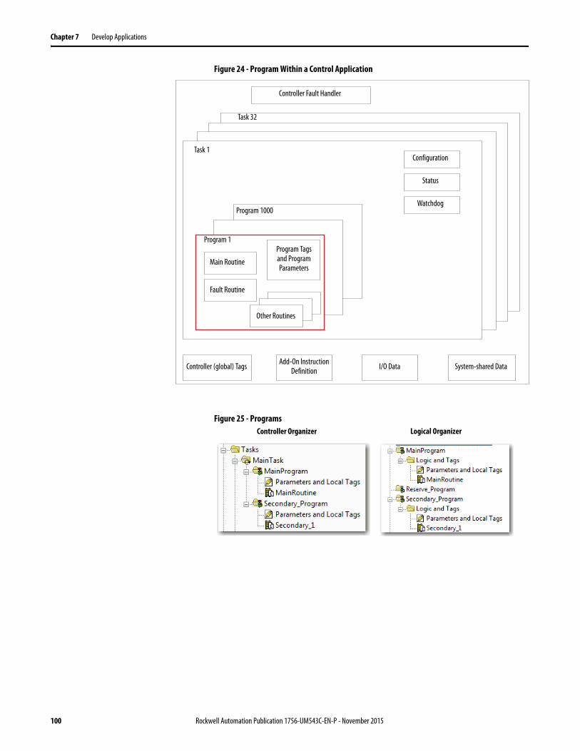
Chapter 7 Develop Applications
Figure 24 - Program Within a Control Application
Figure 25 - Programs
Controller Fault Handler
Task 32
Task 1Configuration
Status
WatchdogProgram 1000
Program 1
Main Routine
Fault Routine
Other Routines
Controller (global) Tags I/O Data System-shared Data
Program Tags and Program Parameters
Add-On Instruction Definition
Controller Organizer Logical Organizer
100 Rockwell Automation Publication 1756-UM543C-EN-P - November 2015
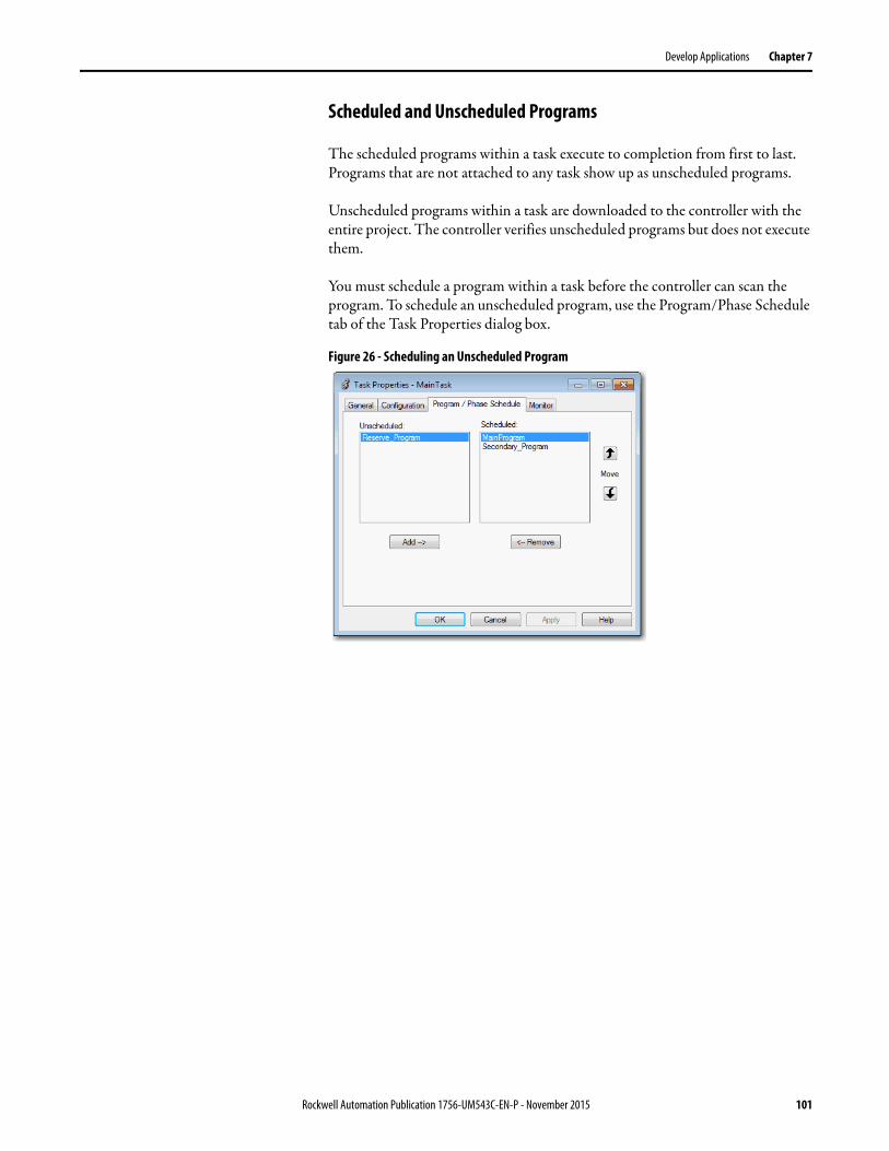
Develop Applications Chapter 7
Scheduled and Unscheduled Programs
The scheduled programs within a task execute to completion from first to last. Programs that are not attached to any task show up as unscheduled programs.
Unscheduled programs within a task are downloaded to the controller with the entire project. The controller verifies unscheduled programs but does not execute them.
You must schedule a program within a task before the controller can scan the program. To schedule an unscheduled program, use the Program/Phase Schedule tab of the Task Properties dialog box.
Figure 26 - Scheduling an Unscheduled Program
Rockwell Automation Publication 1756-UM543C-EN-P - November 2015 101

Chapter 7 Develop Applications
Routines A routine is a set of logic instructions in one programming language, such as Ladder Diagram (ladder logic). Routines provide the executable code for the project in a controller. A routine is similar to a program file or subroutine in a PLC or SLC™ processor.
Each program has a main routine. The main is the first routine to execute when the controller triggers the associated task and calls the associated program. Use logic, such as the Jump to Subroutine ( JSR) instruction, to call other routines.
You can also specify an optional program fault routine. The controller executes this routine if it encounters an instruction-execution fault within any of the routines in the associated program.
Figure 27 - Routines in a Control Application
Figure 28 - Routines
Controller Fault Handler
Task 32
Task 1Configuration
Status
WatchdogProgram 1000
Program 1
Main Routine
Fault Routine
Other Routines
Controller (global) Tags I/O Data System-shared Data
Program Tags and Program Parameters
Add-On Instruction Definition
Routine
Routine
Routine
Routine
Controller Designer Logical Designer
102 Rockwell Automation Publication 1756-UM543C-EN-P - November 2015
Develop Applications Chapter 7
Parameters and Local Tags With a Logix5000 controller, you use a tag (alphanumeric name) to address data (variables). In Logix5000 controllers, there is no fixed, numeric format. The tag name identifies the data and lets you do the following:
• Organize your data to mirror your machinery.• Document your application as you develop it.
This example shows data tags that are created within the scope of the Main Program of the controller.
Figure 29 - Tags Example
There are several guidelines for creating and configuring parameters and local tags for optimal task and program execution. For more information, see the Logix5000 Controllers and I/O Tag Data Programming Manual, publication 1756-PM004.
Controller Organizer —Main Program Parameters and Local Tags
Program Tags Window—Main Program Parameters and Local Tags
Digital I/O Device
Analog I/O Device
Integer ValueStorage Bit
CounterTimer
Rockwell Automation Publication 1756-UM543C-EN-P - November 2015 103
Chapter 7 Develop Applications
Programming Languages The Studio 5000 Logix Designer® Application supports these programming languages.
For information about programming in these languages, see the Logix5000 Controllers Common Procedures Programming Manual, publication 1756-PM001.
Table 23 - ControlLogix Controller Programming Languages
Language Is best used in programs with
Ladder Diagram (LD) Continuous or parallel execution of multiple operations (not sequenced)
Boolean or bit-based operations
Complex logical operations
Message and communication processing
Machine interlocking
Operations that service or maintenance personnel have to interpret to troubleshoot the machine or process
Function Block Diagram (FBD) Continuous process and drive control
Loop control
Calculations in circuit flow
Sequential Function Chart (SFC) High-level management of multiple operations
Repetitive sequence of operations
Batch process
Motion control that uses structured text
State machine operations
Structured Text (ST) Complex mathematical operations
Specialized array or table loop processing
ASCII string handling or protocol processing
104 Rockwell Automation Publication 1756-UM543C-EN-P - November 2015
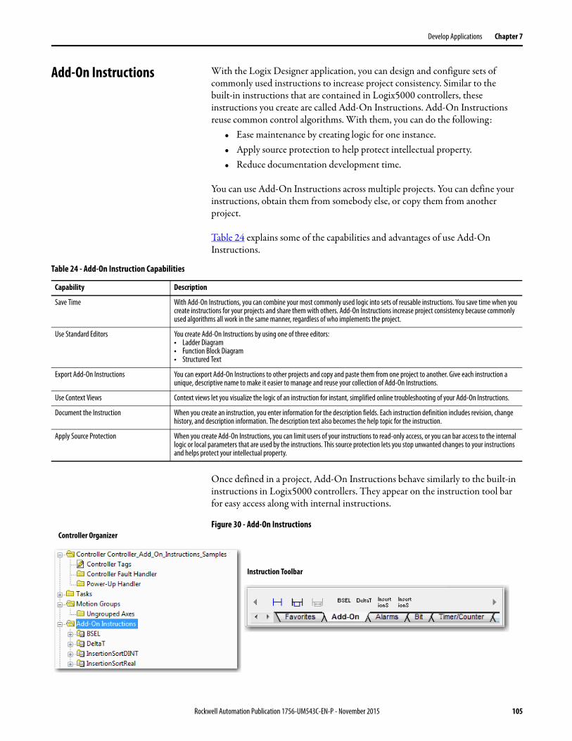
Develop Applications Chapter 7
Add-On Instructions With the Logix Designer application, you can design and configure sets of commonly used instructions to increase project consistency. Similar to the built-in instructions that are contained in Logix5000 controllers, these instructions you create are called Add-On Instructions. Add-On Instructions reuse common control algorithms. With them, you can do the following:
• Ease maintenance by creating logic for one instance.• Apply source protection to help protect intellectual property.• Reduce documentation development time.
You can use Add-On Instructions across multiple projects. You can define your instructions, obtain them from somebody else, or copy them from another project.
Table 24 explains some of the capabilities and advantages of use Add-On Instructions.
Once defined in a project, Add-On Instructions behave similarly to the built-in instructions in Logix5000 controllers. They appear on the instruction tool bar for easy access along with internal instructions.
Figure 30 - Add-On Instructions
Table 24 - Add-On Instruction Capabilities
Capability Description
Save Time With Add-On Instructions, you can combine your most commonly used logic into sets of reusable instructions. You save time when you create instructions for your projects and share them with others. Add-On Instructions increase project consistency because commonly used algorithms all work in the same manner, regardless of who implements the project.
Use Standard Editors You create Add-On Instructions by using one of three editors:• Ladder Diagram• Function Block Diagram• Structured Text
Export Add-On Instructions You can export Add-On Instructions to other projects and copy and paste them from one project to another. Give each instruction a unique, descriptive name to make it easier to manage and reuse your collection of Add-On Instructions.
Use Context Views Context views let you visualize the logic of an instruction for instant, simplified online troubleshooting of your Add-On Instructions.
Document the Instruction When you create an instruction, you enter information for the description fields. Each instruction definition includes revision, change history, and description information. The description text also becomes the help topic for the instruction.
Apply Source Protection When you create Add-On Instructions, you can limit users of your instructions to read-only access, or you can bar access to the internal logic or local parameters that are used by the instructions. This source protection lets you stop unwanted changes to your instructions and helps protect your intellectual property.
Controller Organizer
Instruction Toolbar
Rockwell Automation Publication 1756-UM543C-EN-P - November 2015 105

Chapter 7 Develop Applications
Extended Properties The Extended Properties feature lets you define more information, such as limits, engineering units, or state identifiers for various components within your controller project.
Pass-through behavior is the ability to assign extended properties at a higher level of a structure or Add-On Instruction and have that extended property automatically available for all members. Pass-through behavior is available for descriptions, state identifiers, and engineering units and you can configure it. Configure pass-through behavior on the Project tab of the Controller Properties dialog box. If you choose not to show pass-through properties, only extended properties that have been configured for a given component are displayed.
Pass-through behavior is not available for limits. When an instance of a tag is created, if limits are associated with the data type, the instance is copied.
Use the .@Min and .@Max syntax to define tags that have limits, as there is no indication in the tag browser that limit extended properties are defined for a tag. If you try to use extended properties that have not been defined for a tag, the editors show a visual indication and the routine does not verify. Visual indicators include:
• A rung error in Ladder Logic.• A verification error X in Function Block Diagrams.• The error underlined in Structured Text.
You can access limit extended properties that are defined on tags by using the .@Min and .@Max syntax. However, you cannot write to extended properties values in logic.
For more information on Extended Properties, see the Logix5000 Controllers I/O and Tag Data Programming Manual, publication 1756-PM004.
Component Extended Properties
Tag In the tag editor, add extended properties to a tag.
User-defined data type In the data type editor, add extended properties to data types.
Add-On Instructions In the properties that are associated with the Add-On Instruction definition, add extended properties to Add-On Instructions.
106 Rockwell Automation Publication 1756-UM543C-EN-P - November 2015
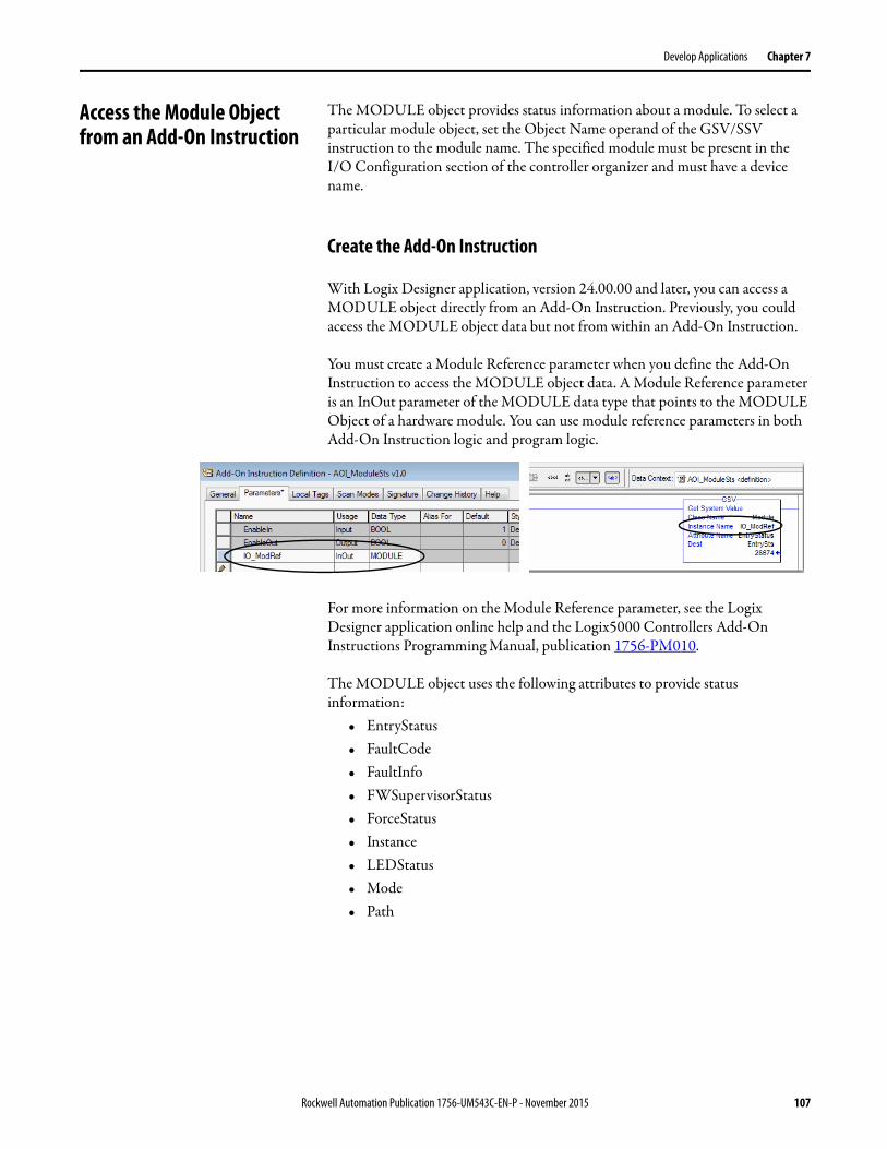
Develop Applications Chapter 7
Access the Module Object from an Add-On Instruction
The MODULE object provides status information about a module. To select a particular module object, set the Object Name operand of the GSV/SSV instruction to the module name. The specified module must be present in the I/O Configuration section of the controller organizer and must have a device name.
Create the Add-On Instruction
With Logix Designer application, version 24.00.00 and later, you can access a MODULE object directly from an Add-On Instruction. Previously, you could access the MODULE object data but not from within an Add-On Instruction.
You must create a Module Reference parameter when you define the Add-On Instruction to access the MODULE object data. A Module Reference parameter is an InOut parameter of the MODULE data type that points to the MODULE Object of a hardware module. You can use module reference parameters in both Add-On Instruction logic and program logic.
For more information on the Module Reference parameter, see the Logix Designer application online help and the Logix5000 Controllers Add-On Instructions Programming Manual, publication 1756-PM010.
The MODULE object uses the following attributes to provide status information:
• EntryStatus• FaultCode• FaultInfo• FWSupervisorStatus• ForceStatus• Instance• LEDStatus• Mode• Path
Rockwell Automation Publication 1756-UM543C-EN-P - November 2015 107
Chapter 7 Develop Applications
Monitoring Controller Status The ControlLogix controller uses Get System Value (GSV) and Set System Value (SSV) instructions to get and set (change) controller data. The controller stores system data in objects. There is no status file, as in the PLC-5® processor.
The GSV instruction retrieves the specified information and places it in the destination. The SSV instruction sets the specified attribute with data from the source. Both instructions are available from the Input/Output tab of the Instruction toolbar.
Figure 31 - GSV and SSV Instructions for Monitoring and Setting Attributes
When you add a GSV/SSV instruction to the program, the object classes, object names, and attribute names for the instruction are shown. For the GSV instruction, you can get values for the available attributes. For the SSV instruction, only the attributes you can set are shown.
Some object types appear repeatedly, so you have to specify the object name. For example, there can be several tasks in your application. Each task has its own Task object that you access by the task name.
The GSV and SSV instructions monitor and set many objects and attributes. See the online help for the GSV and SSV instructions.
Monitoring I/O Connections If communication with a device in the I/O configuration of the controller does not occur in an application-specific period, the communication times out and the controller produces warnings.
The minimum timeout period that, once expired without communication, causes a timeout is 100 ms. The timeout period can be greater, depending on the RPI of the application. For example, if your application uses the default RPI = 20 ms, the timeout period is 160 ms.
For more information on how to determine the time for your application, search the Rockwell Automation® Knowledgebase for answer ID 38535. The document is available at http://www.rockwellautomation.com/knowledgebase.
108 Rockwell Automation Publication 1756-UM543C-EN-P - November 2015
Develop Applications Chapter 7
When a timeout does occur, the controller produces these warnings;
• I/O Fault status information scrolls across the 4-character status display of the controller.
• A shows over the I/O configuration folder and over the devices that have timed out.
• A module fault code is produced, which you can access via the following:– The Module Properties dialog box– A GSV instruction
For more information about I/O faults, see the Logix5000 Controllers Major, Minor, and I/O Faults Programming Manual, publication 1756-PM014.
Determine If I/O Communication Has Timed Out
This example can be used with the ControlLogix 5580 controllers:
• The GSV instruction gets the status of the I/O status indicator (via the LEDStatus attribute of the Module object) and stores it in the IO_LED tag.
• IO_LED is a DINT tag that stores the status of the I/O status indicator or status display on the front of the controller.
• If IO_LED equals 2, then at least one I/O connection has been lost and the Fault_Alert is set.
Figure 32 - GSV Used to Identify I/O Timeout
!
Rockwell Automation Publication 1756-UM543C-EN-P - November 2015 109
Chapter 7 Develop Applications
Determine if I/O Communication to a Specific I/O Module has Timed Out
If communication times out with a device (module) in the I/O configuration of the controller, the controller produces a fault code and fault information for the module. You can use GSV instructions to get fault code and information via the FaultCode and FaultInfo attributes of the Module object.
Automatic Handling of I/O Module Connection Faults
Depending on your application, you may want an I/O connection error to cause the Controller Fault Handler to execute. To do so, set the module property that causes a major fault to result from an I/O connection error. The major fault causes the execution of the Controller Fault Handler.
If it is important to interrupt your normal program scan to handle an I/O connection fault, set the 'Major Fault On Controller If Connection Fails While In Run Mode' and put the logic in the Controller Fault Handler.
Figure 33 - I/O Connection Fault Causes Major Fault
If responding to a failed I/O module connection can wait until the next program scan, put the logic in a normal routine and use the GSV technique that is described on page 109 to call the logic.
First, develop a routine in the Controller Fault Handler that can respond to I/O connection faults. Then, in the Module Properties dialog box of the I/O module or parent communication module, check Major Fault On Controller If Connection Fails While in Run Mode.
For more information about programming the Controller Fault Handler, see the Logix5000 Major, Minor, and I/O Faults Programming Manual, publication 1756-PM014.
TIP Detecting the I/O connection loss takes at least 100 milliseconds, even if the Controller Fault Handler is used.
110 Rockwell Automation Publication 1756-UM543C-EN-P - November 2015
Develop Applications Chapter 7
Sample Controller Projects
Logix Designer includes sample projects that you can copy and modify to fit your application. To access the sample projects, choose Open Sample Project in the Studio 5000® interface and navigate to Samples > ENU > v28 > Rockwell Automation.
Figure 34 - Opening Sample Projects
Rockwell Automation Publication 1756-UM543C-EN-P - November 2015 111

Chapter 7 Develop Applications
Notes:
112 Rockwell Automation Publication 1756-UM543C-EN-P - November 2015
Chapter 8
Develop Motion Applications
ControlLogix® 5580 controllers support Integrated Motion on the EtherNet/IP network on digital and integrated motion interfaces:
• Digital drive interfaces include EtherNet/IP connected drives.• Integrated Motion on an EtherNet/IP network supports Kinetix® 350,
Kinetix 5500, Kinetix 5700, and Kinetix 6500 drives, and PowerFlex® 755.
For more information, see these publications:• Integrated Motion on the EtherNet/IP Network Configuration and
Startup User Manual, publication MOTION-UM003.• Integrated Motion on the EtherNet/IP Network Reference Manual,
Publication MOTION-RM003.
Motion Overview The ControlLogix 5580 controllers support up to 256 axes of integrated motion. The 256 axes can be any combination of CIP, Virtual, and Consumed axes. You can add all axes to one Motion Group, and you can assign any combination of axes to different axis update schedules.
The ControlLogix 5580 controllers do not support Analog or SERCOS motion.
You can associate Integrated Motion axes to any appropriate drive, regardless of whether the communications path to the drive is via the embedded Ethernet port, or over the 1756 backplane (through an Ethernet bridge such as a 1756-EN2T).
Topic Page
Motion Overview 113
Motion Applications 114
Obtain Axis Information 116
Program Motion Control 114
TIP Rockwell Automation recommends using the built-in EtherNet/IP port for high-performance motion applications.
Rockwell Automation Publication 1756-UM543C-EN-P - November 2015 113
Chapter 8 Develop Motion Applications
Motion Applications The configuration process varies, depending on your application and your drive selection.
These are general steps to configure a motion application. See the Integrated Motion on the Ethernet I/P Network Configuration and Startup User Manual, publication MOTION-UM003 for more information.
1. Create a controller project.
2. Add a physical drive to the I/O configuration of the project.
3. Create and configure logical Axes, and associate them with physical drives or virtual axes.
4. Create and configure a Motion Group.
5. Assign Axes to the Motion Group.
6. Specify the motor data source.
7. Display the motor model information.
8. Assign Motor Feedback.
9. Configure the load feedback.
10. Configure the master feedback.
11. Commission an axis.
12. Home an axis.
13. Optionally create and configure Coordinate Systems.
14. Write user logic to control motion.
15. Optionally tune the physical drives for the attached loads.
Program Motion Control The controller provides a set of motion control instructions for your axes:• The controller uses these instructions just like the rest of the Logix5000™
instructions.• Each motion instruction works on one or more axes.• Each motion instruction needs a motion control tag. The tag uses a
MOTION_INSTRUCTION data type and stores the information status of the instruction.
• You can program by using motion control instructions in these programming languages:– Ladder Diagram (LD)– Structured Text (ST)– Sequential Function Chart (SFC)
For more information, see the Logix5000 Controller Motion Instructions Reference Manual, publication MOTION-RM002.
114 Rockwell Automation Publication 1756-UM543C-EN-P - November 2015

Develop Motion Applications Chapter 8
Figure 35 - Motion Control Instruction
Example
In this example, a simple ladder diagram that homes, jogs, and moves an axis.
ATTENTION: Use each motion control tag in only one motion instruction. Unintended operation can result if you reuse the same motion control tag in other motion instructions, or if you write to any of the motion control tag elements.
Motion Control Tag
If Initialize_Pushbutton = on and the axis = off (My_Axis_X.ServoActionStatus = off) then the MSO instruction turns on the axis.
If Home_Pushbutton = on and the axis hasn’t been homed (My_Axis_X.AxisHomedStatus = off) then the MAH instruction homes the axis.
If Jog_Pushbutton = on and the axis = on (My_Axis_X.ServoActionStatus = on) then the MAJ instruction jogs the axis forward at 8 units/second.
If Jog_Pushbutton = off then the MAS instruction stops the axis at 100 units/.second2. Make sure that Change Decel is Yes. Otherwise, the axis decelerates at its maximum speed.
Rockwell Automation Publication 1756-UM543C-EN-P - November 2015 115
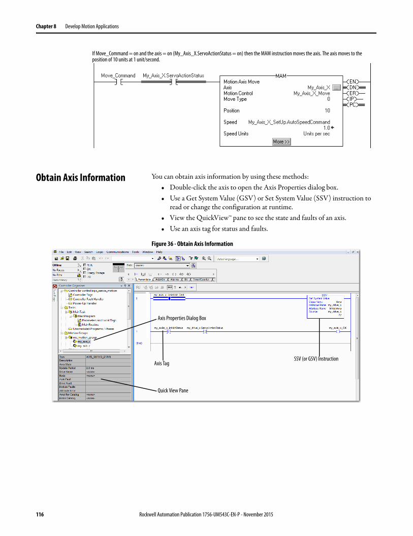
Chapter 8 Develop Motion Applications
Obtain Axis Information You can obtain axis information by using these methods:• Double-click the axis to open the Axis Properties dialog box.• Use a Get System Value (GSV) or Set System Value (SSV) instruction to
read or change the configuration at runtime.• View the QuickView™ pane to see the state and faults of an axis.• Use an axis tag for status and faults.
Figure 36 - Obtain Axis Information
If Move_Command = on and the axis = on (My_Axis_X.ServoActionStatus = on) then the MAM instruction moves the axis. The axis moves to the position of 10 units at 1 unit/second.
Axis Properties Dialog Box
SSV (or GSV) InstructionAxis Tag
Quick View Pane
116 Rockwell Automation Publication 1756-UM543C-EN-P - November 2015
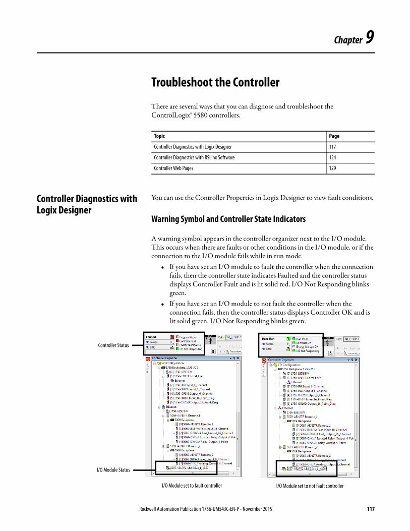
Chapter 9
Troubleshoot the Controller
There are several ways that you can diagnose and troubleshoot the ControlLogix® 5580 controllers.
Controller Diagnostics with Logix Designer
You can use the Controller Properties in Logix Designer to view fault conditions.
Warning Symbol and Controller State Indicators
A warning symbol appears in the controller organizer next to the I/O module. This occurs when there are faults or other conditions in the I/O module, or if the connection to the I/O module fails while in run mode.
• If you have set an I/O module to fault the controller when the connection fails, then the controller state indicates Faulted and the controller status displays Controller Fault and is lit solid red. I/O Not Responding blinks green.
• If you have set an I/O module to not fault the controller when the connection fails, then the controller status displays Controller OK and is lit solid green. I/O Not Responding blinks green.
Topic Page
Controller Diagnostics with Logix Designer 117
Controller Diagnostics with RSLinx Software 124
Controller Web Pages 129
I/O Module set to fault controller I/O Module set to not fault controller
Controller Status
I/O Module Status
Rockwell Automation Publication 1756-UM543C-EN-P - November 2015 117
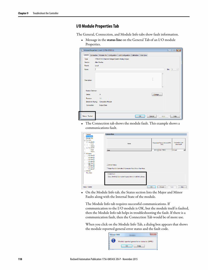
Chapter 9 Troubleshoot the Controller
I/O Module Properties Tab
The General, Connection, and Module Info tabs show fault information.• Message in the status line on the General Tab of an I/O module
Properties.
• The Connection tab shows the module fault. This example shows a communications fault.
• On the Module Info tab, the Status section lists the Major and Minor Faults along with the Internal State of the module.
The Module Info tab requires successful communications. If communication to the I/O module is OK, but the module itself is faulted, then the Module Info tab helps in troubleshooting the fault. If there is a communication fault, then the Connection Tab would be of more use.
When you click on the Module Info Tab, a dialog box appears that shows the module reported general error status and the fault code.
118 Rockwell Automation Publication 1756-UM543C-EN-P - November 2015
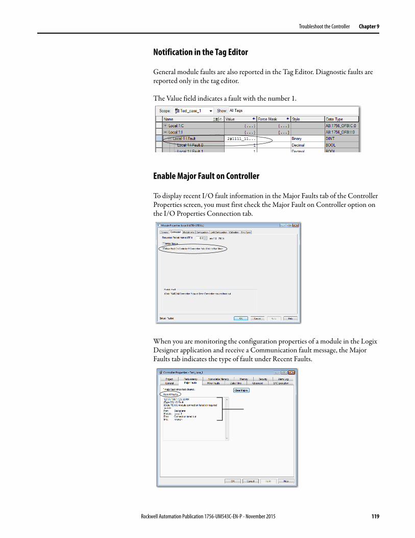
Troubleshoot the Controller Chapter 9
Notification in the Tag Editor
General module faults are also reported in the Tag Editor. Diagnostic faults are reported only in the tag editor.
The Value field indicates a fault with the number 1.
Enable Major Fault on Controller
To display recent I/O fault information in the Major Faults tab of the Controller Properties screen, you must first check the Major Fault on Controller option on the I/O Properties Connection tab.
When you are monitoring the configuration properties of a module in the Logix Designer application and receive a Communication fault message, the Major Faults tab indicates the type of fault under Recent Faults.
Rockwell Automation Publication 1756-UM543C-EN-P - November 2015 119
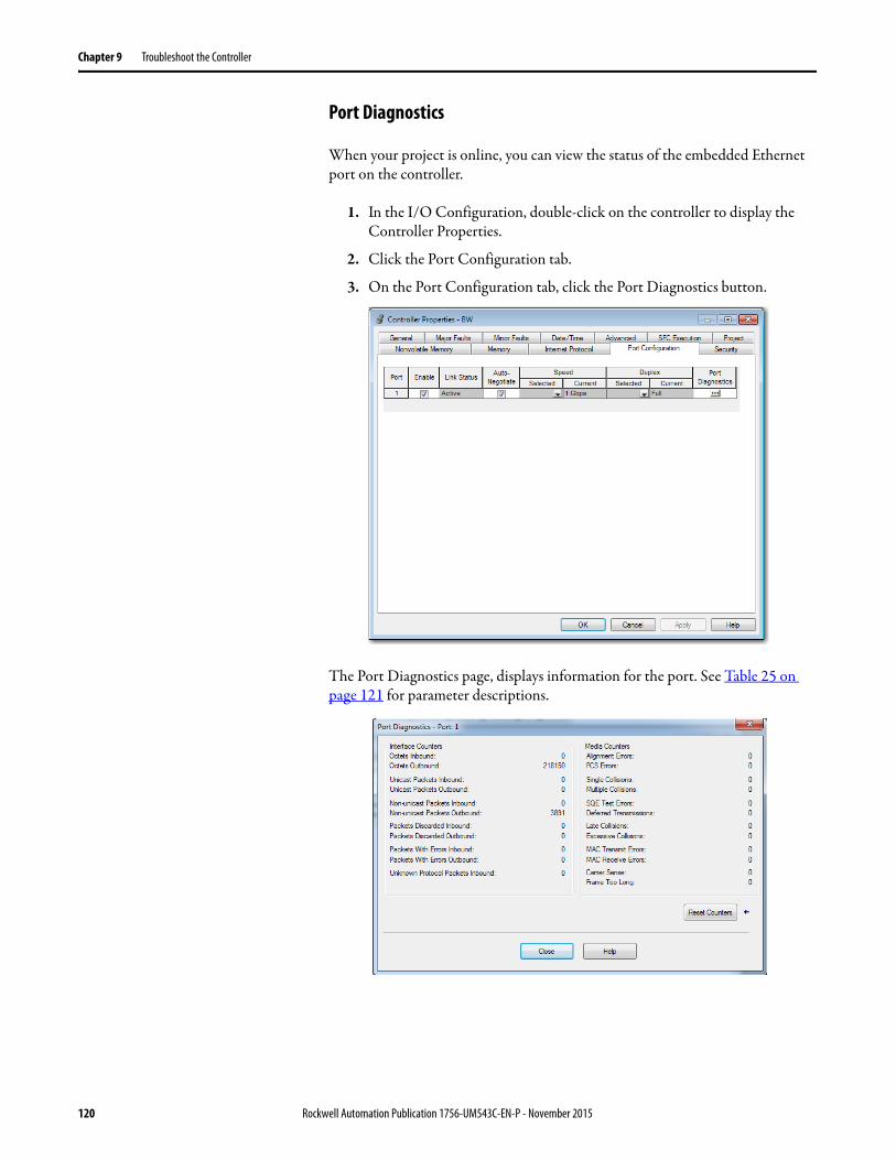
Chapter 9 Troubleshoot the Controller
Port Diagnostics
When your project is online, you can view the status of the embedded Ethernet port on the controller.
1. In the I/O Configuration, double-click on the controller to display the Controller Properties.
2. Click the Port Configuration tab.
3. On the Port Configuration tab, click the Port Diagnostics button.
The Port Diagnostics page, displays information for the port. See Table 25 on page 121 for parameter descriptions.
120 Rockwell Automation Publication 1756-UM543C-EN-P - November 2015
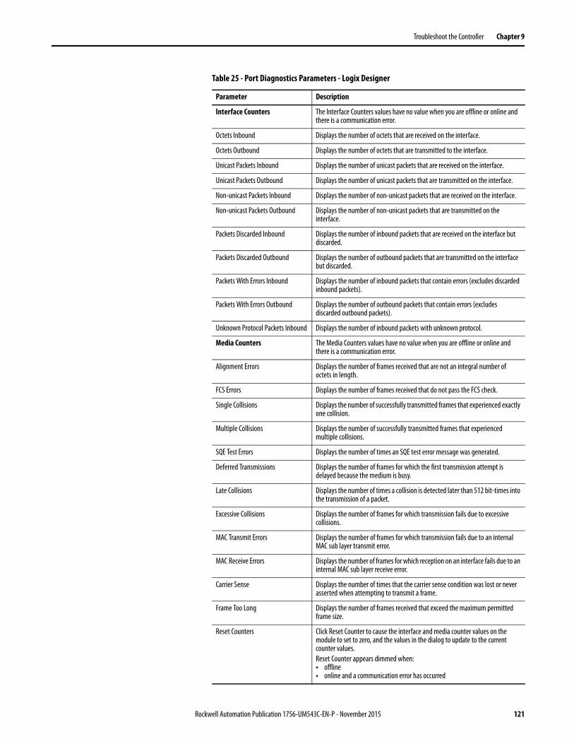
Troubleshoot the Controller Chapter 9
Table 25 - Port Diagnostics Parameters - Logix Designer
Parameter Description
Interface Counters The Interface Counters values have no value when you are offline or online and there is a communication error.
Octets Inbound Displays the number of octets that are received on the interface.
Octets Outbound Displays the number of octets that are transmitted to the interface.
Unicast Packets Inbound Displays the number of unicast packets that are received on the interface.
Unicast Packets Outbound Displays the number of unicast packets that are transmitted on the interface.
Non-unicast Packets Inbound Displays the number of non-unicast packets that are received on the interface.
Non-unicast Packets Outbound Displays the number of non-unicast packets that are transmitted on the interface.
Packets Discarded Inbound Displays the number of inbound packets that are received on the interface but discarded.
Packets Discarded Outbound Displays the number of outbound packets that are transmitted on the interface but discarded.
Packets With Errors Inbound Displays the number of inbound packets that contain errors (excludes discarded inbound packets).
Packets With Errors Outbound Displays the number of outbound packets that contain errors (excludes discarded outbound packets).
Unknown Protocol Packets Inbound Displays the number of inbound packets with unknown protocol.
Media Counters The Media Counters values have no value when you are offline or online and there is a communication error.
Alignment Errors Displays the number of frames received that are not an integral number of octets in length.
FCS Errors Displays the number of frames received that do not pass the FCS check.
Single Collisions Displays the number of successfully transmitted frames that experienced exactly one collision.
Multiple Collisions Displays the number of successfully transmitted frames that experienced multiple collisions.
SQE Test Errors Displays the number of times an SQE test error message was generated.
Deferred Transmissions Displays the number of frames for which the first transmission attempt is delayed because the medium is busy.
Late Collisions Displays the number of times a collision is detected later than 512 bit-times into the transmission of a packet.
Excessive Collisions Displays the number of frames for which transmission fails due to excessive collisions.
MAC Transmit Errors Displays the number of frames for which transmission fails due to an internal MAC sub layer transmit error.
MAC Receive Errors Displays the number of frames for which reception on an interface fails due to an internal MAC sub layer receive error.
Carrier Sense Displays the number of times that the carrier sense condition was lost or never asserted when attempting to transmit a frame.
Frame Too Long Displays the number of frames received that exceed the maximum permitted frame size.
Reset Counters Click Reset Counter to cause the interface and media counter values on the module to set to zero, and the values in the dialog to update to the current counter values.Reset Counter appears dimmed when:• offline• online and a communication error has occurred
Rockwell Automation Publication 1756-UM543C-EN-P - November 2015 121

Chapter 9 Troubleshoot the Controller
Advanced Time Sync
The Advanced Time Sync dialog displays information that is related to CIP Sync time synchronization. The information appears only if the project is online, and Time Synchronization is enabled on the Date/Time tab.
1. On the Date/Time, click the Advanced button.
The Advanced Time Sync dialog box opens. See Table 26 on page 123 for parameter descriptions.
122 Rockwell Automation Publication 1756-UM543C-EN-P - November 2015
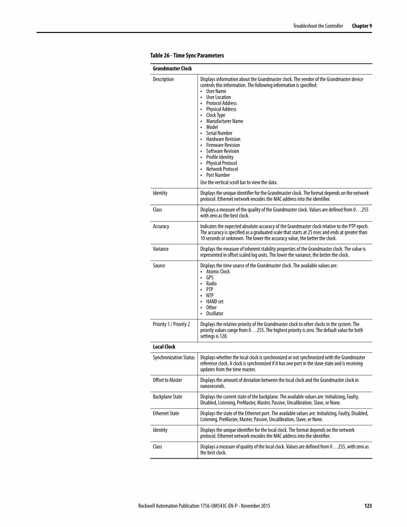
Troubleshoot the Controller Chapter 9
Table 26 - Time Sync Parameters
Grandmaster Clock
Description Displays information about the Grandmaster clock. The vendor of the Grandmaster device controls this information. The following information is specified:• User Name • User Location• Protocol Address• Physical Address• Clock Type• Manufacturer Name• Model• Serial Number• Hardware Revision• Firmware Revision• Software Revision• Profile Identity• Physical Protocol• Network Protocol• Port NumberUse the vertical scroll bar to view the data.
Identity Displays the unique identifier for the Grandmaster clock. The format depends on the network protocol. Ethernet network encodes the MAC address into the identifier.
Class Displays a measure of the quality of the Grandmaster clock. Values are defined from 0…255 with zero as the best clock.
Accuracy Indicates the expected absolute accuracy of the Grandmaster clock relative to the PTP epoch. The accuracy is specified as a graduated scale that starts at 25 nsec and ends at greater than 10 seconds or unknown. The lower the accuracy value, the better the clock.
Variance Displays the measure of inherent stability properties of the Grandmaster clock. The value is represented in offset scaled log units. The lower the variance, the better the clock.
Source Displays the time source of the Grandmaster clock. The available values are:• Atomic Clock• GPS• Radio• PTP• NTP• HAND set• Other• Oscillator
Priority 1 / Priority 2 Displays the relative priority of the Grandmaster clock to other clocks in the system. The priority values range from 0…255. The highest priority is zero. The default value for both settings is 128.
Local Clock
Synchronization Status Displays whether the local clock is synchronized or not synchronized with the Grandmaster reference clock. A clock is synchronized if it has one port in the slave state and is receiving updates from the time master.
Offset to Master Displays the amount of deviation between the local clock and the Grandmaster clock in nanoseconds.
Backplane State Displays the current state of the backplane. The available values are: Initializing, Faulty, Disabled, Listening, PreMaster, Master, Passive, Uncalibration, Slave, or None.
Ethernet State Displays the state of the Ethernet port. The available values are: Initializing, Faulty, Disabled, Listening, PreMaster, Master, Passive, Uncalibration, Slave, or None.
Identity Displays the unique identifier for the local clock. The format depends on the network protocol. Ethernet network encodes the MAC address into the identifier.
Class Displays a measure of quality of the local clock. Values are defined from 0…255, with zero as the best clock.
Rockwell Automation Publication 1756-UM543C-EN-P - November 2015 123
Chapter 9 Troubleshoot the Controller
Controller Diagnostics with RSLinx Software
You can also view diagnostic information in RSLinx® software.
1. From the Communications menu, choose RSWho.
The RSWho dialog box appears.
2. Navigate to the Ethernet network.
3. Right-click the controller and choose Module Statistics.
Accuracy Indicates the expected absolute accuracy of the local clock relative to the PTP epoch. The accuracy is specified as a graduated scale that starts at 25 nsec and ends at greater than 10 seconds or unknown. The lower the accuracy value, the better the clock.
Variance Displays the measure of inherent stability properties of the local clock. The value is represented in offset scaled log units. The lower the variance, the better the clock.
Source Displays the time source of the local clock. The available values are:• Atomic Clock• GPS• Terrestrial Radio• PTP• NTP• HAND set• Other• Oscillator
Table 26 - Time Sync Parameters (Continued)
124 Rockwell Automation Publication 1756-UM543C-EN-P - November 2015
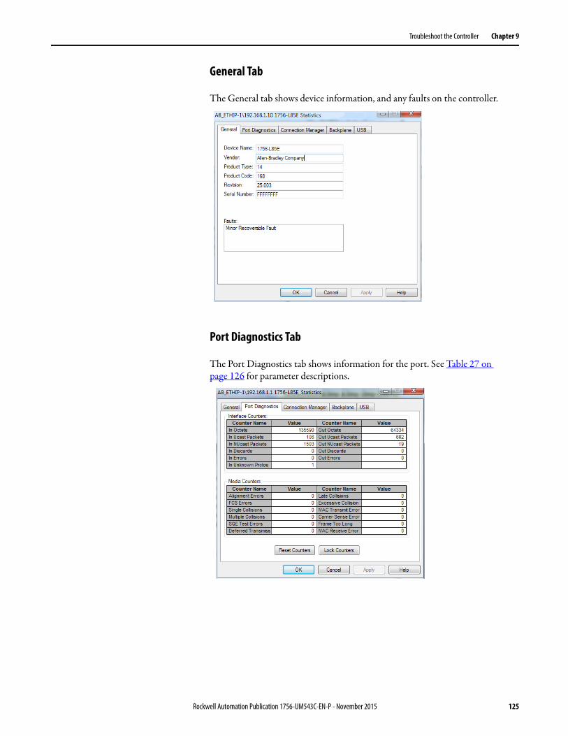
Troubleshoot the Controller Chapter 9
General Tab
The General tab shows device information, and any faults on the controller.
Port Diagnostics Tab
The Port Diagnostics tab shows information for the port. See Table 27 on page 126 for parameter descriptions.
Rockwell Automation Publication 1756-UM543C-EN-P - November 2015 125
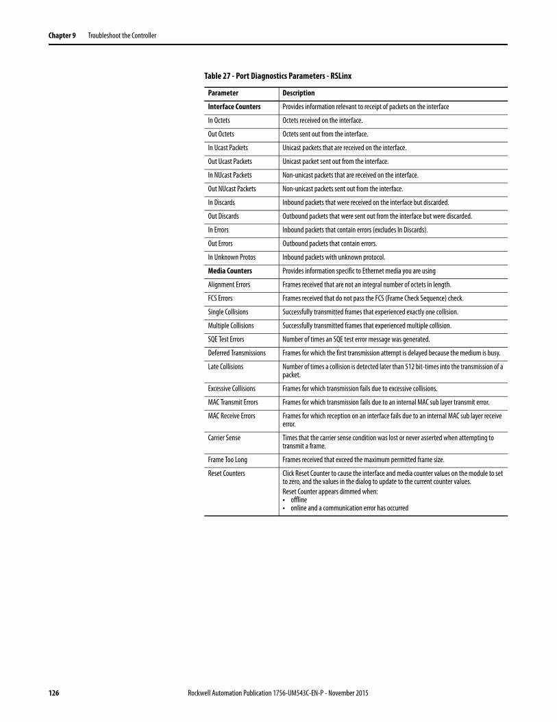
Chapter 9 Troubleshoot the Controller
Table 27 - Port Diagnostics Parameters - RSLinx
Parameter Description
Interface Counters Provides information relevant to receipt of packets on the interface
In Octets Octets received on the interface.
Out Octets Octets sent out from the interface.
In Ucast Packets Unicast packets that are received on the interface.
Out Ucast Packets Unicast packet sent out from the interface.
In NUcast Packets Non-unicast packets that are received on the interface.
Out NUcast Packets Non-unicast packets sent out from the interface.
In Discards Inbound packets that were received on the interface but discarded.
Out Discards Outbound packets that were sent out from the interface but were discarded.
In Errors Inbound packets that contain errors (excludes In Discards).
Out Errors Outbound packets that contain errors.
In Unknown Protos Inbound packets with unknown protocol.
Media Counters Provides information specific to Ethernet media you are using
Alignment Errors Frames received that are not an integral number of octets in length.
FCS Errors Frames received that do not pass the FCS (Frame Check Sequence) check.
Single Collisions Successfully transmitted frames that experienced exactly one collision.
Multiple Collisions Successfully transmitted frames that experienced multiple collision.
SQE Test Errors Number of times an SQE test error message was generated.
Deferred Transmissions Frames for which the first transmission attempt is delayed because the medium is busy.
Late Collisions Number of times a collision is detected later than 512 bit-times into the transmission of a packet.
Excessive Collisions Frames for which transmission fails due to excessive collisions.
MAC Transmit Errors Frames for which transmission fails due to an internal MAC sub layer transmit error.
MAC Receive Errors Frames for which reception on an interface fails due to an internal MAC sub layer receive error.
Carrier Sense Times that the carrier sense condition was lost or never asserted when attempting to transmit a frame.
Frame Too Long Frames received that exceed the maximum permitted frame size.
Reset Counters Click Reset Counter to cause the interface and media counter values on the module to set to zero, and the values in the dialog to update to the current counter values.Reset Counter appears dimmed when:• offline• online and a communication error has occurred
126 Rockwell Automation Publication 1756-UM543C-EN-P - November 2015

Troubleshoot the Controller Chapter 9
Connection Manager Tab
See Table 28 for a description of the Connection Manager properties.
Table 28 - Connection Manager Properties
Field Description
Requests Number of open/close connection requests that this module has received.
Format Rejects Number of open/close connection requests this module has rejected because the request was not formatted correctly or because some parameter value was not within a supported range of values.
Resource Rejects Number of open connection requests that this module has rejected because the module did not have enough resources (buffers, link bandwidth, or CPU utilization) to honor the request.
Other Rejects Number of open/close connection requests a module rejects.
Timeouts Number of connections that are not explicitly closed by the connection originator, but closed by this module because they were not being used.
Rockwell Automation Publication 1756-UM543C-EN-P - November 2015 127
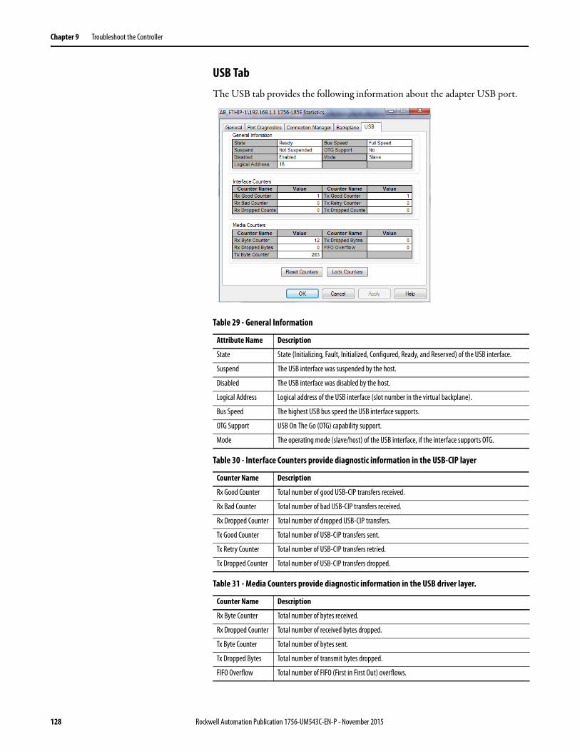
Chapter 9 Troubleshoot the Controller
USB TabThe USB tab provides the following information about the adapter USB port.
Table 29 - General Information
Attribute Name Description
State State (Initializing, Fault, Initialized, Configured, Ready, and Reserved) of the USB interface.
Suspend The USB interface was suspended by the host.
Disabled The USB interface was disabled by the host.
Logical Address Logical address of the USB interface (slot number in the virtual backplane).
Bus Speed The highest USB bus speed the USB interface supports.
OTG Support USB On The Go (OTG) capability support.
Mode The operating mode (slave/host) of the USB interface, if the interface supports OTG.
Table 30 - Interface Counters provide diagnostic information in the USB-CIP layer
Counter Name Description
Rx Good Counter Total number of good USB-CIP transfers received.
Rx Bad Counter Total number of bad USB-CIP transfers received.
Rx Dropped Counter Total number of dropped USB-CIP transfers.
Tx Good Counter Total number of USB-CIP transfers sent.
Tx Retry Counter Total number of USB-CIP transfers retried.
Tx Dropped Counter Total number of USB-CIP transfers dropped.
Table 31 - Media Counters provide diagnostic information in the USB driver layer.
Counter Name Description
Rx Byte Counter Total number of bytes received.
Rx Dropped Counter Total number of received bytes dropped.
Tx Byte Counter Total number of bytes sent.
Tx Dropped Bytes Total number of transmit bytes dropped.
FIFO Overflow Total number of FIFO (First in First Out) overflows.
128 Rockwell Automation Publication 1756-UM543C-EN-P - November 2015

Troubleshoot the Controller Chapter 9
Controller Web Pages The controller provides diagnostic web pages that track controller performance, network performance, and backplane performance.
To access the diagnostic web pages, follow these steps.
1. Open your web browser.
2. In the Address field, type the IP address of the controller and press Enter.
To access the diagnostic web pages, open the Diagnostics folder in the left-most navigation bar, and click the link for each diagnostic web page you need to monitor.
The Diagnostics webpages provide communications and messaging data for the controller.
The Advanced diagnostics webpages provide data about the TCP/IP Network and Precision Time Protocol.
Also see:• Tasks Webpage on page 130• Browse Chassis Webpage on page 131
Rockwell Automation Publication 1756-UM543C-EN-P - November 2015 129
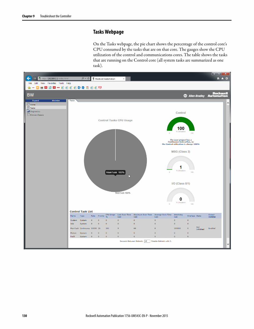
Chapter 9 Troubleshoot the Controller
Tasks Webpage
On the Tasks webpage, the pie chart shows the percentage of the control core's CPU consumed by the tasks that are on that core. The gauges show the CPU utilization of the control and communications cores. The table shows the tasks that are running on the Control core (all system tasks are summarized as one task).
130 Rockwell Automation Publication 1756-UM543C-EN-P - November 2015
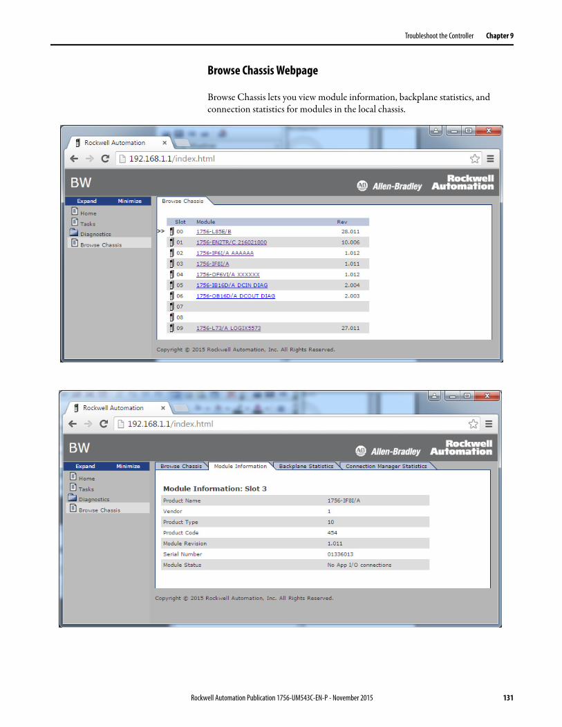
Troubleshoot the Controller Chapter 9
Browse Chassis Webpage
Browse Chassis lets you view module information, backplane statistics, and connection statistics for modules in the local chassis.
Rockwell Automation Publication 1756-UM543C-EN-P - November 2015 131

Chapter 9 Troubleshoot the Controller
Notes:
132 Rockwell Automation Publication 1756-UM543C-EN-P - November 2015

Appendix A
Status Indicators
The ControlLogix® 5580 controllers have six status indicators and one four-character scrolling status display.
This figure shows the location of the 4-Character status display and status indicators.
Figure 37 - Status Display and Indicators
Topic Page
4-Character Status Display 134
Controller Status Indicators 142
EtherNet/IP Indicators 143
Thermal Monitoring and Thermal Fault Behavior 144
32511-M
4-Character Scrolling Status Display, see page 134
Status Indicators, see page 142EtherNet/IP Status Indicators, see page 143
Rockwell Automation Publication 1756-UM543C-EN-P - 1756-UM543C-EN-P 2015 133
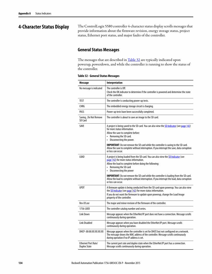
Appendix A Status Indicators
4-Character Status Display The ControlLogix 5580 controller 4-character status display scrolls messages that provide information about the firmware revision, energy storage status, project status, Ethernet port status, and major faults of the controller.
General Status Messages
The messages that are described in Table 32 are typically indicated upon powerup, powerdown, and while the controller is running to show the status of the controller.
Table 32 - General Status Messages
Message Interpretation
No message is indicated The controller is Off.Check the OK indicator to determine if the controller is powered and determine the state of the controller.
TEST The controller is conducting power-up tests.
CHRG The embedded energy storage circuit is charging.
PASS Power-up tests have been successfully completed.
Saving...Do Not Remove SD Card
The controller is about to save an image to the SD card.
SAVE A project is being saved to the SD card. You can also view the SD Indicator (see page 142) for more status information.Allow the save to complete before:• Removing the SD card.• Disconnecting the power.
IMPORTANT: Do not remove the SD card while the controller is saving to the SD card. Allow the save to complete without interruption. If you interrupt the save, data corruption or loss can occur.
LOAD A project is being loaded from the SD card. You can also view the SD Indicator (see page 142) for more status information.Allow the load to complete before doing the following:• Removing the SD card• Disconnecting the power
IMPORTANT: Do not remove the SD card while the controller is loading from the SD card. Allow the load to complete without interruption. If you interrupt the load, data corruption or loss can occur.
UPDT A firmware update is being conducted from the SD card upon powerup. You can also view the SD Indicator (see page 142) for more status information.If you do not want the firmware to update upon powerup, change the Load Image property of the controller.
Rev XX.xxx The major and minor revision of the firmware of the controller.
1756-L8XX The controller catalog number and series.
Link Down Message appears when the EtherNet/IP port does not have a connection. Message scrolls continuously during operation.
Link Disabled Message appears when you have disabled the EtherNet/IP port. Message scrolls continuously during operation.
DHCP- 00:00:XX:XX:XX:XX Message appears when the controller is set for DHCP, but not configured on a network. The message shows the MAC address of the controller. Message scrolls continuously during operation if no IP address is set.
Ethernet Port Rate/Duplex State
The current port rate and duplex state when the EtherNet/IP port has a connection. Message scrolls continuously during operation.
134 Rockwell Automation Publication 1756-UM543C-EN-P - November 2015

Status Indicators Appendix A
IP Address The IP address of the controller. Appears on powerup, then scrolls continuously during operation. If the IP address is not yet set, then the MAC address appears.
Duplicate IP - 00:00:XX:XX:XX:XX
Message appears when the controller detects a device with the same IP Address on the network. The message shows the MAC address of the device with the duplicate IP Address. Message scrolls continuously during operation.
No Project No project is loaded on the controller.To load a project, do one of the following:• Use Logix Designer application to download the project to the controller• Use an SD card to load a project to the controller
Project Name The name of the project that is loaded on the controller.
BUSY The I/O modules that are associated with the controller are not yet fully powered.Allow time for powerup and I/O module self-testing.
Corrupt Certificate Received
The security certificate that is associated with the firmware is corrupted.Go to http://www.rockwellautomation.com/support/ and download the firmware revision you are trying to update to. Replace the firmware revision that you have previously installed with that posted on the Technical Support website.
Corrupt Image Received The firmware file is corrupted.Go to http://www.rockwellautomation.com/support/ and download the firmware revision you are trying to update to. Replace the firmware revision that you have previously installed with that posted on the Technical Support website.
Backup Energy HW Failure - Save Project
A failure with the embedded storage circuit has occurred, and the controller is incapable of saving the program in the event of a powerdown. If you see this message, then save your program to the SD card before you remove power, and then replace the module.
Backup Energy Low - Save Project
The embedded storage circuit does not have sufficient energy to enable the controller to save the program in the event of a powerdown. If you see this message, then save your program to the SD card before you remove power, and then replace the module.
Flash in Progress A firmware update that is initiated via ControlFLASH or AutoFlash utilities is in progress.Allow the firmware update to complete without interruption.
Firmware Installation Required
The controller is using boot firmware (that is revision 1.xxx) and requires a firmware update.
SD Card Locked An SD card that is locked is installed.
Table 32 - General Status Messages (Continued)
Message Interpretation
Rockwell Automation Publication 1756-UM543C-EN-P - November 2015 135

Appendix A Status Indicators
Fault Messages
If the controller displays a fault, these messages can be indicated on the status display.
Table 33 - Fault Messages
Message Interpretation
Major Fault TXX:CXX message A major fault of Type XX and Code XX has been detected.For example, if the status display indicates Major Fault T04:C42 Invalid JMP Target, a JMP instruction is programmed to jump to an invalid LBL instruction.For details about major recoverable faults, see the Logix5000™ Major, Minor, and I/O Fault Codes Programming Manual, publication 1756-PM014.
I/O Fault Local:X #XXXX message An I/O fault has occurred on a module in the local chassis. The slot number and fault code are indicated along with a brief description. For example, I/O Fault Local:3 #0107 Connection Not Found indicates that a connection to the local I/O module in slot three is not open.Take corrective action specific to the type of fault indicated.For details about each I/O fault code, see the Logix5000 Major, Minor, and I/O Fault Codes Programming Manual, publication 1756-PM014.
I/O Fault ModuleName #XXXX message An I/O fault has occurred on a module in a remote chassis. The name of the faulted module is indicated with the fault code and brief description of the fault.For example, I/O Fault My_Module #0107 Connection Not Found indicates that a connection to the module named My_Module is not open.Take corrective action specific to the type of fault indicated.For details about each I/O fault code, see the Logix5000 Major, Minor, and I/O Fault Codes Programming Manual, publication 1756-PM014.
I/O Fault ModuleParent:X #XXXX message An I/O fault has occurred on a module in a remote chassis. The parent name of the module is indicated because no module name is configured in the I/O Configuration tree of Logix Designer application. In addition, the fault code is indicated with a brief description of the fault.For example, I/O Fault My_CNet:3 #0107 Connection Not Found indicates that a connection to a module in slot 3 of the chassis with the communication module named My_CNet is not open.Take corrective action specific to the type of fault indicated.For details about each I/O fault code, see the Logix5000 Major, Minor, and I/O Fault Codes Programming Manual, publication 1756-PM014.
X I/O Faults I/O faults are present and X = the number of I/O faults present.If there are multiple I/O faults, the controller indicates the first fault reported. As each I/O fault is resolved, the number of indicated faults decreases and the I/O Fault message indicates the next reported fault.Take corrective action specific to the type of fault indicated.For details about each I/O fault code, see the Logix5000 Major, Minor, and I/O Fault Codes Programming Manual, publication 1756-PM014.
136 Rockwell Automation Publication 1756-UM543C-EN-P - November 2015
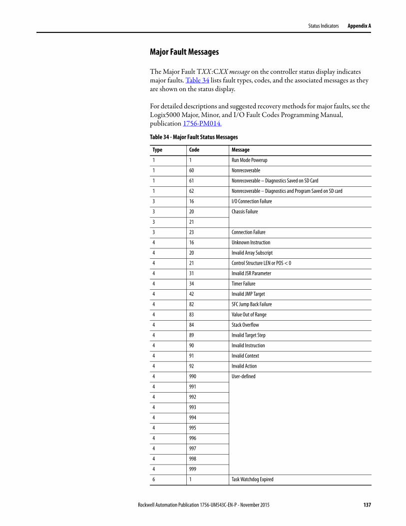
Status Indicators Appendix A
Major Fault Messages
The Major Fault TXX:CXX message on the controller status display indicates major faults. Table 34 lists fault types, codes, and the associated messages as they are shown on the status display.
For detailed descriptions and suggested recovery methods for major faults, see the Logix5000 Major, Minor, and I/O Fault Codes Programming Manual, publication 1756-PM014.
Table 34 - Major Fault Status Messages
Type Code Message
1 1 Run Mode Powerup
1 60 Nonrecoverable
1 61 Nonrecoverable – Diagnostics Saved on SD Card
1 62 Nonrecoverable – Diagnostics and Program Saved on SD card
3 16 I/O Connection Failure
3 20 Chassis Failure
3 21
3 23 Connection Failure
4 16 Unknown Instruction
4 20 Invalid Array Subscript
4 21 Control Structure LEN or POS < 0
4 31 Invalid JSR Parameter
4 34 Timer Failure
4 42 Invalid JMP Target
4 82 SFC Jump Back Failure
4 83 Value Out of Range
4 84 Stack Overflow
4 89 Invalid Target Step
4 90 Invalid Instruction
4 91 Invalid Context
4 92 Invalid Action
4 990 User-defined
4 991
4 992
4 993
4 994
4 995
4 996
4 997
4 998
4 999
6 1 Task Watchdog Expired
Rockwell Automation Publication 1756-UM543C-EN-P - November 2015 137
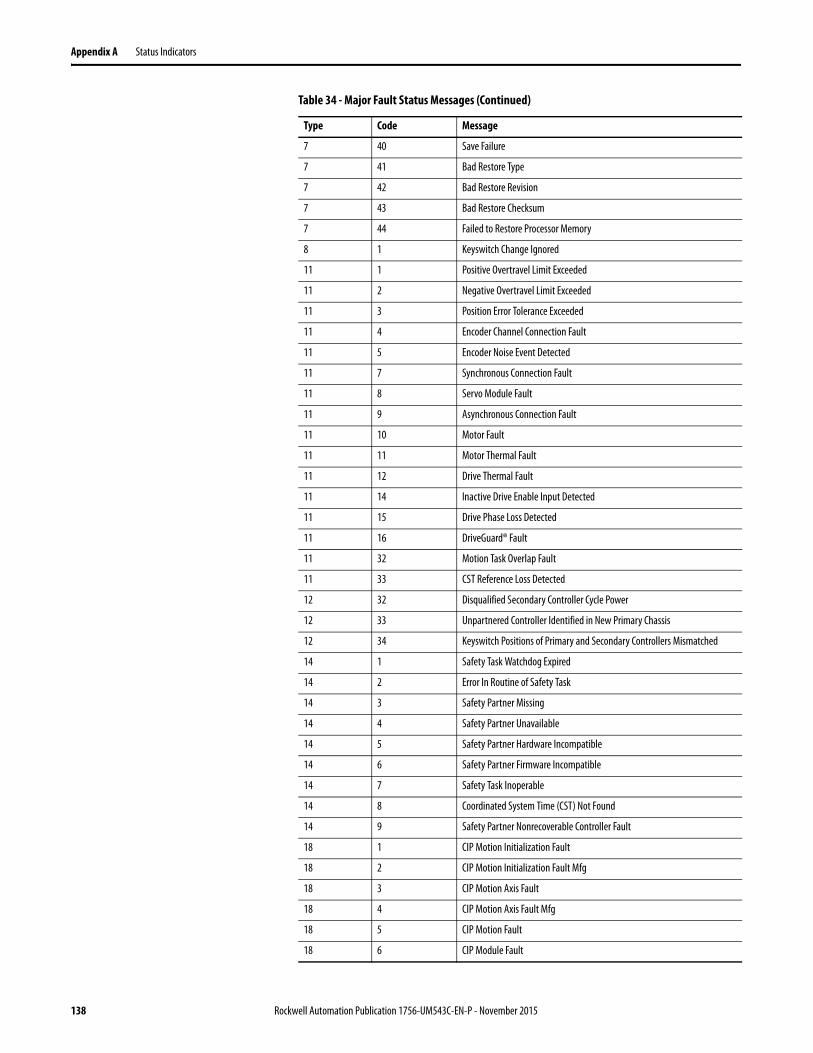
Appendix A Status Indicators
7 40 Save Failure
7 41 Bad Restore Type
7 42 Bad Restore Revision
7 43 Bad Restore Checksum
7 44 Failed to Restore Processor Memory
8 1 Keyswitch Change Ignored
11 1 Positive Overtravel Limit Exceeded
11 2 Negative Overtravel Limit Exceeded
11 3 Position Error Tolerance Exceeded
11 4 Encoder Channel Connection Fault
11 5 Encoder Noise Event Detected
11 7 Synchronous Connection Fault
11 8 Servo Module Fault
11 9 Asynchronous Connection Fault
11 10 Motor Fault
11 11 Motor Thermal Fault
11 12 Drive Thermal Fault
11 14 Inactive Drive Enable Input Detected
11 15 Drive Phase Loss Detected
11 16 DriveGuard® Fault
11 32 Motion Task Overlap Fault
11 33 CST Reference Loss Detected
12 32 Disqualified Secondary Controller Cycle Power
12 33 Unpartnered Controller Identified in New Primary Chassis
12 34 Keyswitch Positions of Primary and Secondary Controllers Mismatched
14 1 Safety Task Watchdog Expired
14 2 Error In Routine of Safety Task
14 3 Safety Partner Missing
14 4 Safety Partner Unavailable
14 5 Safety Partner Hardware Incompatible
14 6 Safety Partner Firmware Incompatible
14 7 Safety Task Inoperable
14 8 Coordinated System Time (CST) Not Found
14 9 Safety Partner Nonrecoverable Controller Fault
18 1 CIP Motion Initialization Fault
18 2 CIP Motion Initialization Fault Mfg
18 3 CIP Motion Axis Fault
18 4 CIP Motion Axis Fault Mfg
18 5 CIP Motion Fault
18 6 CIP Module Fault
Table 34 - Major Fault Status Messages (Continued)
Type Code Message
138 Rockwell Automation Publication 1756-UM543C-EN-P - November 2015
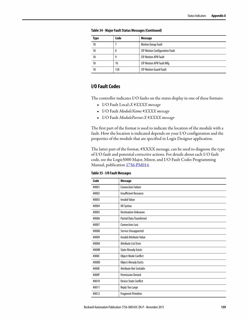
Status Indicators Appendix A
I/O Fault Codes
The controller indicates I/O faults on the status display in one of these formats:• I/O Fault Local:X #XXXX message• I/O Fault ModuleName #XXXX message• I/O Fault ModuleParent:X #XXXX message
The first part of the format is used to indicate the location of the module with a fault. How the location is indicated depends on your I/O configuration and the properties of the module that are specified in Logix Designer application.
The latter part of the format, #XXXX message, can be used to diagnose the type of I/O fault and potential corrective actions. For details about each I/O fault code, see the Logix5000 Major, Minor, and I/O Fault Codes Programming Manual, publication 1756-PM014.
18 7 Motion Group Fault
18 8 CIP Motion Configuration Fault
18 9 CIP Motion APR Fault
18 10 CIP Motion APR Fault Mfg
18 128 CIP Motion Guard Fault
Table 35 - I/O Fault Messages
Code Message
#0001 Connection Failure
#0002 Insufficient Resource
#0003 Invalid Value
#0004 IOI Syntax
#0005 Destination Unknown
#0006 Partial Data Transferred
#0007 Connection Lost
#0008 Service Unsupported
#0009 Invalid Attribute Value
#000A Attribute List Error
#000B State Already Exists
#000C Object Mode Conflict
#000D Object Already Exists
#000E Attribute Not Settable
#000F Permission Denied
#0010 Device State Conflict
#0011 Reply Too Large
#0012 Fragment Primitive
Table 34 - Major Fault Status Messages (Continued)
Type Code Message
Rockwell Automation Publication 1756-UM543C-EN-P - November 2015 139
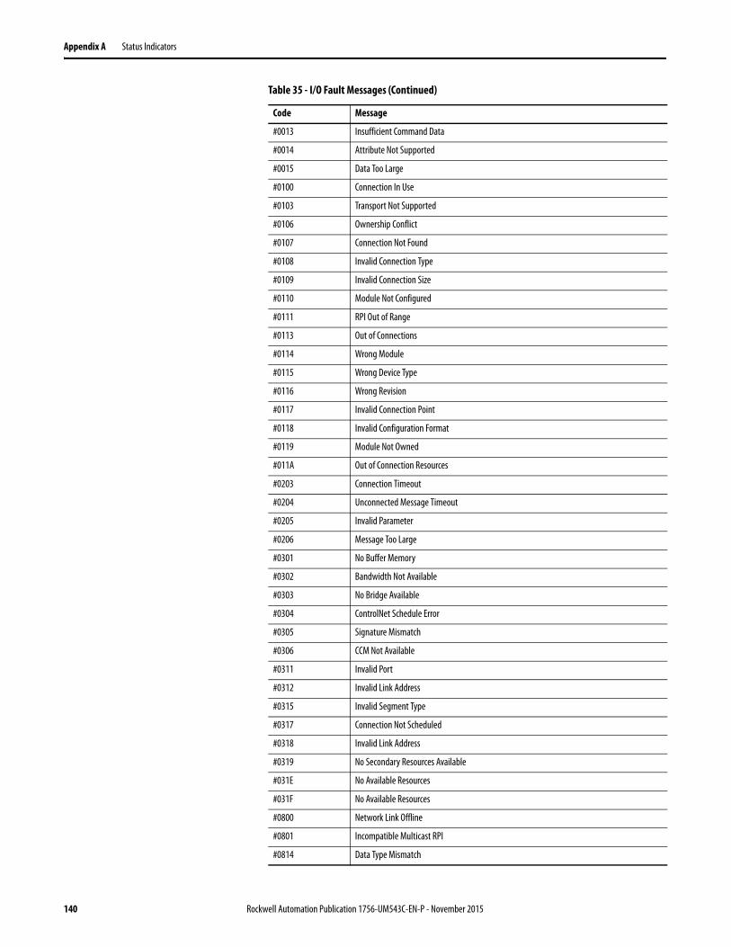
Appendix A Status Indicators
#0013 Insufficient Command Data
#0014 Attribute Not Supported
#0015 Data Too Large
#0100 Connection In Use
#0103 Transport Not Supported
#0106 Ownership Conflict
#0107 Connection Not Found
#0108 Invalid Connection Type
#0109 Invalid Connection Size
#0110 Module Not Configured
#0111 RPI Out of Range
#0113 Out of Connections
#0114 Wrong Module
#0115 Wrong Device Type
#0116 Wrong Revision
#0117 Invalid Connection Point
#0118 Invalid Configuration Format
#0119 Module Not Owned
#011A Out of Connection Resources
#0203 Connection Timeout
#0204 Unconnected Message Timeout
#0205 Invalid Parameter
#0206 Message Too Large
#0301 No Buffer Memory
#0302 Bandwidth Not Available
#0303 No Bridge Available
#0304 ControlNet Schedule Error
#0305 Signature Mismatch
#0306 CCM Not Available
#0311 Invalid Port
#0312 Invalid Link Address
#0315 Invalid Segment Type
#0317 Connection Not Scheduled
#0318 Invalid Link Address
#0319 No Secondary Resources Available
#031E No Available Resources
#031F No Available Resources
#0800 Network Link Offline
#0801 Incompatible Multicast RPI
#0814 Data Type Mismatch
Table 35 - I/O Fault Messages (Continued)
Code Message
140 Rockwell Automation Publication 1756-UM543C-EN-P - November 2015
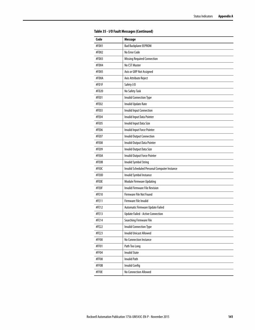
Status Indicators Appendix A
#FD01 Bad Backplane EEPROM
#FD02 No Error Code
#FD03 Missing Required Connection
#FD04 No CST Master
#FD05 Axis or GRP Not Assigned
#FD0A Axis Attribute Reject
#FD1F Safety I/O
#FD20 No Safety Task
#FE01 Invalid Connection Type
#FE02 Invalid Update Rate
#FE03 Invalid Input Connection
#FE04 Invalid Input Data Pointer
#FE05 Invalid Input Data Size
#FE06 Invalid Input Force Pointer
#FE07 Invalid Output Connection
#FE08 Invalid Output Data Pointer
#FE09 Invalid Output Data Size
#FE0A Invalid Output Force Pointer
#FE0B Invalid Symbol String
#FE0C Invalid Scheduled Personal Computer Instance
#FE0D Invalid Symbol Instance
#FE0E Module Firmware Updating
#FE0F Invalid Firmware File Revision
#FE10 Firmware File Not Found
#FE11 Firmware File Invalid
#FE12 Automatic Firmware Update Failed
#FE13 Update Failed - Active Connection
#FE14 Searching Firmware File
#FE22 Invalid Connection Type
#FE23 Invalid Unicast Allowed
#FF00 No Connection Instance
#FF01 Path Too Long
#FF04 Invalid State
#FF08 Invalid Path
#FF0B Invalid Config
#FF0E No Connection Allowed
Table 35 - I/O Fault Messages (Continued)
Code Message
Rockwell Automation Publication 1756-UM543C-EN-P - November 2015 141
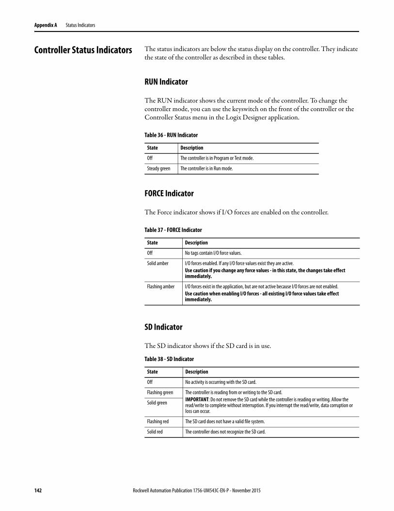
Appendix A Status Indicators
Controller Status Indicators The status indicators are below the status display on the controller. They indicate the state of the controller as described in these tables.
RUN Indicator
The RUN indicator shows the current mode of the controller. To change the controller mode, you can use the keyswitch on the front of the controller or the Controller Status menu in the Logix Designer application.
FORCE Indicator
The Force indicator shows if I/O forces are enabled on the controller.
SD Indicator
The SD indicator shows if the SD card is in use.
Table 36 - RUN Indicator
State Description
Off The controller is in Program or Test mode.
Steady green The controller is in Run mode.
Table 37 - FORCE Indicator
State Description
Off No tags contain I/O force values.
Solid amber I/O forces enabled. If any I/O force values exist they are active.Use caution if you change any force values - in this state, the changes take effect immediately.
Flashing amber I/O forces exist in the application, but are not active because I/O forces are not enabled.Use caution when enabling I/O forces - all existing I/O force values take effect immediately.
Table 38 - SD Indicator
State Description
Off No activity is occurring with the SD card.
Flashing green The controller is reading from or writing to the SD card.IMPORTANT: Do not remove the SD card while the controller is reading or writing. Allow the read/write to complete without interruption. If you interrupt the read/write, data corruption or loss can occur.
Solid green
Flashing red The SD card does not have a valid file system.
Solid red The controller does not recognize the SD card.
142 Rockwell Automation Publication 1756-UM543C-EN-P - November 2015
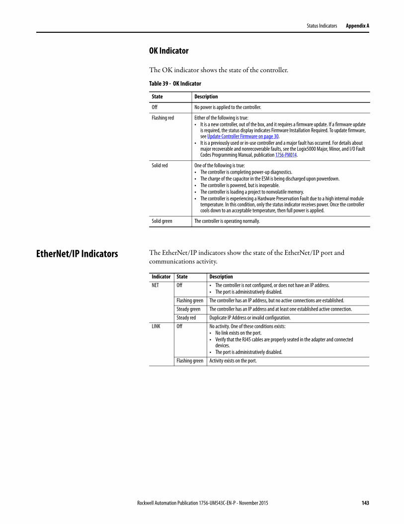
Status Indicators Appendix A
OK Indicator
The OK indicator shows the state of the controller.
EtherNet/IP Indicators The EtherNet/IP indicators show the state of the EtherNet/IP port and communications activity.
Table 39 - OK Indicator
State Description
Off No power is applied to the controller.
Flashing red Either of the following is true:• It is a new controller, out of the box, and it requires a firmware update. If a firmware update
is required, the status display indicates Firmware Installation Required. To update firmware, see Update Controller Firmware on page 30.
• It is a previously used or in-use controller and a major fault has occurred. For details about major recoverable and nonrecoverable faults, see the Logix5000 Major, Minor, and I/O Fault Codes Programming Manual, publication 1756-PM014.
Solid red One of the following is true:• The controller is completing power-up diagnostics.• The charge of the capacitor in the ESM is being discharged upon powerdown.• The controller is powered, but is inoperable.• The controller is loading a project to nonvolatile memory.• The controller is experiencing a Hardware Preservation Fault due to a high internal module
temperature. In this condition, only the status indicator receives power. Once the controller cools down to an acceptable temperature, then full power is applied.
Solid green The controller is operating normally.
Indicator State DescriptionNET Off • The controller is not configured, or does not have an IP address.
• The port is administratively disabled.Flashing green The controller has an IP address, but no active connections are established.Steady green The controller has an IP address and at least one established active connection.Steady red Duplicate IP Address or invalid configuration.
LINK Off No activity. One of these conditions exists:• No link exists on the port.• Verify that the RJ45 cables are properly seated in the adapter and connected
devices.• The port is administratively disabled.
Flashing green Activity exists on the port.
Rockwell Automation Publication 1756-UM543C-EN-P - November 2015 143
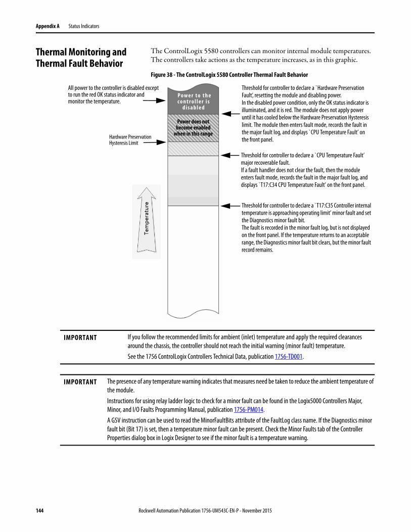
Appendix A Status Indicators
Thermal Monitoring and Thermal Fault Behavior
The ControlLogix 5580 controllers can monitor internal module temperatures. The controllers take actions as the temperature increases, as in this graphic.
Figure 38 - The ControlLogix 5580 Controller Thermal Fault Behavior
Threshold for controller to declare a `Hardware Preservation Fault’, resetting the module and disabling power.In the disabled power condition, only the OK status indicator is illuminated, and it is red. The module does not apply power until it has cooled below the Hardware Preservation Hysteresis limit. The module then enters fault mode, records the fault in the major fault log, and displays `CPU Temperature Fault’ on the front panel.
Threshold for controller to declare a `CPU Temperature Fault’ major recoverable fault.If a fault handler does not clear the fault, then the module enters fault mode, records the fault in the major fault log, and displays `T17:C34 CPU Temperature Fault’ on the front panel.
Threshold for controller to declare a ̀ T17:C35 Controller internal temperature is approaching operating limit’ minor fault and set the Diagnostics minor fault bit. The fault is recorded in the minor fault log, but is not displayed on the front panel. If the temperature returns to an acceptable range, the Diagnostics minor fault bit clears, but the minor fault record remains.
P o w e r t o t h e c o n t r o l l e r i s
d i s a b l e d
Hardware Preservation Hysteresis Limit
Power does not become enabled
when in this range
All power to the controller is disabled except to run the red OK status indicator and monitor the temperature.
IMPORTANT If you follow the recommended limits for ambient (inlet) temperature and apply the required clearances around the chassis, the controller should not reach the initial warning (minor fault) temperature.See the 1756 ControlLogix Controllers Technical Data, publication 1756-TD001.
IMPORTANT The presence of any temperature warning indicates that measures need be taken to reduce the ambient temperature of the module.Instructions for using relay ladder logic to check for a minor fault can be found in the Logix5000 Controllers Major, Minor, and I/O Faults Programming Manual, publication 1756-PM014.A GSV instruction can be used to read the MinorFaultBits attribute of the FaultLog class name. If the Diagnostics minor fault bit (Bit 17) is set, then a temperature minor fault can be present. Check the Minor Faults tab of the Controller Properties dialog box in Logix Designer to see if the minor fault is a temperature warning.
144 Rockwell Automation Publication 1756-UM543C-EN-P - November 2015
Index
Numerics10/100/1000 231756-CN2
uses 631756-CN2R
uses 631756-CN2RXT
uses 631756-CNB
uses 631756-CNBR
uses 631756-DHRIO 66
communication via 67uses
remote I/O 681756-DHRIOXT
uses 66, 681756-DNB
uses 651756-EN2F
uses 591756-EN2T
uses 591756-EN2TR
uses 591756-EN2TRXT
uses 601756-EN2TSC
uses 601756-EN2TXT
uses 601756-EN3TR
uses 601756-ENBT
uses 591756-EWEB
uses 601756-IF8H
uses 711756-N2 831756-N2XT 831756-RIO
uses 681784-SD1
load from 49store to 46
1784-SD2load from 49store to 46
1788-CN2DNuses 65
1788-CN2FFRuses 70
1788-EN2DNRuses 65
1788-EN2FFRuses 70
Aadd
local I/O 83remote I/O 86, 88
Add-On Instructionsin project 105
applicationelements 95networks and 57
AutoFlashupdate 34
axesconsumed 113virtual 113
axisobtain information 116
Bbehavior
thermal fault 144BOOTP/DHCP server
setting IP network address 25-26
Ccache
message options 79messages
about 78chassis
ControlLogixlist 83
communicationallow 76block 76Data Highway Plus 66, 67Foundation Fieldbus 70HART 71network options 14path
set 37universal remote I/O 68
Communication Drivers 17configure
DHCP server 26motion 113
connectionDeviceNet
network 65EtherNet/IP 74message, required 78scheduled
ControlNet 78unscheduled
Rockwell Automation Publication 1756-UM543C-EN-P - November 2015 145
Index
ControlNet 78consume
data 77continuous task 98control data 75ControlFLASH software 31controller 44
behavior 76communication path
set 37ControlLogix 5580
communication options 14design system with 14download project 39features 14firmware 30
obtain 30go online 37monitor
connections 108, 109operation mode
change with Logix Designer 45change with mode switch 43
program 99routine 102status display 134status indicators 142tags 103tasks 96upload a project 40
ControlLogixchassis
list 83design system 14I/O
remote 85selection 81
remote I/Olocal 83
slot filler 83ControlLogix 5580 controller
features 14ControlLogix system
configuration options 12minimum requirements 11
ControlLogix-XTchassis
list 83ControlNet
module capability 62module features 62module list 63network 61scheduled connection
scheduled connection 78unscheduled connection
unscheduled connection 78
DData Highway Plus 66design
system 14
developapplications 95motion applications 113
DeviceNetconnection use 65module
memory 65network 64software for 65
DH+ 66DHCP 25, 26diagnostics
with Logix Designer 117port configuration category 120time sync category 122
with RSLinx software 124connection manager tab 127general tab 125port diagnostics tab 125USB tab 128
display 134DNS addressing 24, 28
EtherNet/IP network parameters 24domain name 24double data rate (DDR) 61download
project 39duplicate IP address
detection 27resolution 27
Eelectronic keying
about 82elements
control application 95error
script file 32Ethernet 23Ethernet port
diagnosticsLogix Designer 120with RSLinx software 125
disable 55EtherNet/IP
communication driver 17, 18connections 74module features 59network 58nodes 74software for 60
EtherNet/IP networkconnect to network 24direct connection 15integrated motion 15number of nodes supported 15parameters for DNS addressing 24
event task 98
146 Rockwell Automation Publication 1756-UM543C-EN-P - November 2015
Index
Ffault
cpu temperature 144hardware preservation 144recoverable 144
fault codeuse GSV to get 110
fault handlerexecute at I/O fault 110
fault messages 136I/O 139
features 14controller
communication 14programming 14
filler slotslot filler 83
firmwarecontroller 30obtain 30required 30security certificate, error 32update with AutoFlash, use 34update with ControlFlash 31
FORCE indicator 142Foundation Fieldbus 70
Ggateway 24general status messages 134GSV
fault code 110monitor
connection 109
Hhandshake 76HART. See Highway Addressable Remote
Transducer.Highway Addressable Remote Transducer 71host name 24
II/O
connection error 110ControlLogix
remote 85selection 81
determine data update 93fault codes 139remote 85
I/O configurationadd
local I/O 83remote I/O 86, 88while online 92
indicator 142FORCE 142OK 143SD 142
instructionmotion 114
integrated motionon the EtherNet/IP network 15
IP addressesdefinition 24DHCP server 26duplicate address detection 27duplicate address resolution 27
Lload
from memory card 49local
I/Oadd 83
remote I/O 83Logix controller 73Logix Designer
change controller operation mode 45Logix Designer application
Add-On Instructions 105program 99routine 102tags 103tasks 96
Mmemory
DeviceNet module 65memory card 46
load from 49other tasks 51store project to card 46store to 46
messageabout 78cache 79
determine if 79fault 136status display 134
minimum requirements 11mode switch 43
change controller operation mode 43position 44
moduleControlNet 62, 63EtherNet/IP 59
motionabout 113application 113instructions 114program 114
MVI56-HARTuses 71
Rockwell Automation Publication 1756-UM543C-EN-P - November 2015 147
Index
Nnetwork
application and 57controller options 14ControlNet 61Data Highway Plus 67DeviceNet 64DH+. See Data Highway Plus.EtherNet/IP 58Foundation Fieldbus 70HART 71universal remote I/O 68
network addressDNS addressing 28
network parametersDNS addressing 24domain name 24gateway 24host name 24IP addresses 24subnet mask 24
nodes on an EtherNet/IP network 74
Oobtain
axis information 116firmware 30
OK indicator 143online
addto I/O configuration 92
go 37
Ppath
setcommunication 37
periodic task 98port diagnostics 120
with RSLinx software 125priority
task 99produce
data 77produce/consume
data 77program
in project 99scheduled 101unscheduled 101
programming languages 104programming practices 76
projectAdd-On Instructions 105download 39elements 95go online 37program 99routine 102tags 103tasks 96upload 40
Rreceive
messages 78remote
I/O 85remote I/O 66
add 86, 88ControlLogix
local 83universal 68
requiredconnections
messages 78reset button 52
stage 1 reset 53stage 2 reset 54
RIO. See universal remote I/Oroutine
in project 102RSLinx software
controller diagnostics 124RSWho
setpath 37
Sscheduled
program 101script file
error 32SD card 15
other tasks 51store to 46
SD indicator 142Secure Digital (SD) card 15, 46
load from 49store project to card 46
security certificateerror 32
selectionI/O 81
sendmessages 78
sercos 113set IP network address
BOOTP/DHCP server 25-26
148 Rockwell Automation Publication 1756-UM543C-EN-P - November 2015

Index
softwareDeviceNet and 65EtherNet/IP and 60required
USB 29specifications 9, 14, 144status
fault messages 136indicators 142messages
display 134monitor
connections 108, 109status display 134
storeto memory card 46
subnet mask 24system 14
Ttag
consume 77in project 103produce 77
taskcontinuous 98event 98in project 96periodic 98priority 99
temperaturelimit 144warning 144
thermal monitoring 144
Uuniversal remote I/O 68
communicate via 69unscheduled
program 101update
determine frequency 93update firmware
AutoFlash, use 34upload
project 40USB
communication driver 17, 20connect cable 29software required 29
Rockwell Automation Publication 1756-UM543C-EN-P - November 2015 149

Index
Notes:
150 Rockwell Automation Publication 1756-UM543C-EN-P - November 2015

Publication 1756-UM543C-EN-P - November 2015Supersedes Publication 1756-UM543B-EN-P - November 2015 Copyright © 2015 Rockwell Automation, Inc. All rights reserved. Printed in the U.S.A.
Rockwell Automation Support
Rockwell Automation provides technical information on the Web to assist you in using its products.At http://www.rockwellautomation.com/support you can find technical and application notes, sample code, and links to software service packs. You can also visit our Support Center at https://rockwellautomation.custhelp.com/ for software updates, support chats and forums, technical information, FAQs, and to sign up for product notification updates.
In addition, we offer multiple support programs for installation, configuration, and troubleshooting. For more information, contact your local distributor or Rockwell Automation representative, or visithttp://www.rockwellautomation.com/services/online-phone.
Installation Assistance
If you experience a problem within the first 24 hours of installation, review the information that is contained in this manual. You can contact Customer Support for initial help in getting your product up and running.
New Product Satisfaction Return
Rockwell Automation tests all of its products to help ensure that they are fully operational when shipped from the manufacturing facility. However, if your product is not functioning and needs to be returned, follow these procedures.
Documentation Feedback
Your comments will help us serve your documentation needs better. If you have any suggestions on how to improve this document, complete this form, publication RA-DU002, available at http://www.rockwellautomation.com/literature/.
United States or Canada 1.440.646.3434
Outside United States or Canada Use the Worldwide Locator at http://www.rockwellautomation.com/rockwellautomation/support/overview.page, or contact your local Rockwell Automation representative.
United States Contact your distributor. You must provide a Customer Support case number (call the phone number above to obtain one) to your distributor to complete the return process.
Outside United States Please contact your local Rockwell Automation representative for the return procedure.
Rockwell Otomasyon Ticaret A.Ş., Kar Plaza İş Merkezi E Blok Kat:6 34752 İçerenköy, İstanbul, Tel: +90 (216) 5698400
Rockwell Automation maintains current product environmental information on its website athttp://www.rockwellautomation.com/rockwellautomation/about-us/sustainability-ethics/product-environmental-compliance.page.