Control System — Student's copy - IES Academyiesacademy.com/docs/Control System 2011.pdf ·...
12
Control System Contents Chapter Topic Page No Chapter-1 Introduction Theory at a glance Previous Years GATE Questions Previous Years IES Questions Previous Years GATE Answer Previous Years IES Answer 2 2 8 8 10 10 Chapter-2 Transfer Function, Block Diagrams and Signal Flow Graphs Theory at a glance Previous Years GATE Questions Previous Years IES Questions Previous Years GATE Answer Previous Years IES Answer 12 12 19 21 24 25 Chapter-3 Mathematical Modeling Control System Theory at a glance Previous Years IES Questions 35Previous Years IES Answer 28 28 33 35 Chapter-4 Time Response Analysis of Control System Theory at a glance Previous Years GATE Questions Previous Years IES Questions Previous Years GATE Answer Previous Years IES Answer 37 37 49 52 59 62
Transcript of Control System — Student's copy - IES Academyiesacademy.com/docs/Control System 2011.pdf ·...

Control System Contents
Chapter Topic Page No
Chapter-1 Introduction Theory at a glance Previous Years GATE Questions Previous Years IES Questions Previous Years GATE Answer Previous Years IES Answer
2 2 8 8 10 10
Chapter-2 Transfer Function, Block Diagrams and Signal Flow Graphs Theory at a glance Previous Years GATE Questions Previous Years IES Questions Previous Years GATE Answer Previous Years IES Answer
12 12 19 21 24 25
Chapter-3 Mathematical Modeling Control System Theory at a glance Previous Years IES Questions 35Previous Years IES Answer
28 28 33 35
Chapter-4 Time Response Analysis of Control System Theory at a glance Previous Years GATE Questions Previous Years IES Questions Previous Years GATE Answer Previous Years IES Answer
37 37 49 52 59 62

India’s No 1 Control System IES Academy Contents
www.iesacademy.com Email: [email protected] Page-1 ________________________________________________________________________ 25, 1st Floor, Jia Sarai, Near IIT. New Delhi-16 Ph: 011-26537570, 9810958290
Chapter-5 Frequency Analysis Theory at a glance Previous Years IES Questions Previous Years IES Answer
69 69 74 76
Chapter-6 Stability Analysis of Control System Theory at a glance Previous Years GATE Questions Previous Years IES Questions Previous Years GATE Answer Previous Years IES Answer
77 77 92 98 110 118
Chapter-7 Root — Locus Technique Theory at a glance Previous Years GATE Questions Previous Years IES Questions Previous Years GATE Answer Previous Years IES Answer
132 132 136 138 143 146
Chapter-8 Compensators Theory at a glance Previous Years GATE Questions Previous Years IES Questions Previous Years GATE Answer Previous Years IES Answer
150 150 155 156 160 161
Chapter-9 Industrial Controllers Theory at a glance Previous Years GATE Questions Previous Years IES Questions Previous Years GATE Answer Previous Years IES Answer
165 165 171 172 176 177
Chapter-10 Introduction to State Space Variable Theory at a glance Previous Years GATE Questions Previous Years IES Questions Previous Years GATE Answer Previous Years IES Answer
180 180 188 190 192 195

India’s No 1 Control System IES Academy Chapter 1
www.iesacademy.com Email: [email protected] Page-2 ________________________________________________________________________ 25, 1st Floor, Jia Sarai, Near IIT. New Delhi-16 Ph: 011-26537570, 9810958290
Introduction Contents for this chapter 1. Introduction
2. Open–Loop System
3. Mathematical Model for Open-loop Control System
4. Closed-Loop Control System
5. Mathematical Model for Closed-Loop System
6. Comparison of Open Loop and Closed Loop
7. Laplace Transform
8. Basic Laplace Transform Theorem
9. Summary
Theory at a Glance (For IES, GATE, PSU & JTO)
1. Introduction Control system is a combination of elements arranged in a planned manner. Where each element causes an effect to produce a desire output.
Example of control systems 1. System for the control of position. 2. System for the control of velocity.
2. Open–Loop System 1. No feedback in open loop system is used. 2. Control system (open-loop) depends only on the accuracy of input calibration.
Example of open-loop control system 1. Traffic signal light 2. Electric lift 3. Automatic washing machine
3. Mathematical Model for Open-loop Control System C = GR
India’s No 1 Control System IES Academy Chapter 1
www.iesacademy.com Email: [email protected] Page-3 ________________________________________________________________________ 25, 1st Floor, Jia Sarai, Near IIT. New Delhi-16 Ph: 011-26537570, 9810958290
Where, G = gain of system C = o/p of system R = input
Points: 1. Feedback system is not used for improving stability. 2. An open-loop system may become unstable when we used negative feedback.
4. Closed-Loop Control System In a closed loop control system the output has an effect on control action through a feedback.
Example of closed-loop system: 1. D.C. Motor speed control 2. Radar tracking system 3. Auto pilot system
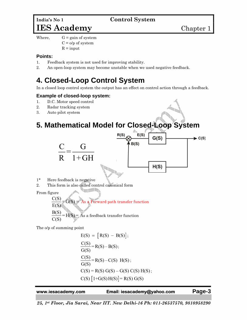
5. Mathematical Model for Closed-Loop System
C G=R 1+GH
1* Here feedback is negative 2. This form is also called control canonical form
From figure
C(S) = G(S) =E(S)
As a Forward path transfer function
B(S) = H(S) =C(S)
As a feedback transfer function
The o/p of summing point
[ ]E(S) R(S) – B(S)= ;
C(S) = R(S) – B(S)G(S)
;
C(S) = R(S) – C(S) H(S)G(S)
;
C(S) = R(S) G(S) – G(S) C(S) H(S) ;
[ ]C(S) 1+G(S) H(S) = R(S) G(S)
India’s No 1 Control System IES Academy Chapter 1
www.iesacademy.com Email: [email protected] Page-4 ________________________________________________________________________ 25, 1st Floor, Jia Sarai, Near IIT. New Delhi-16 Ph: 011-26537570, 9810958290
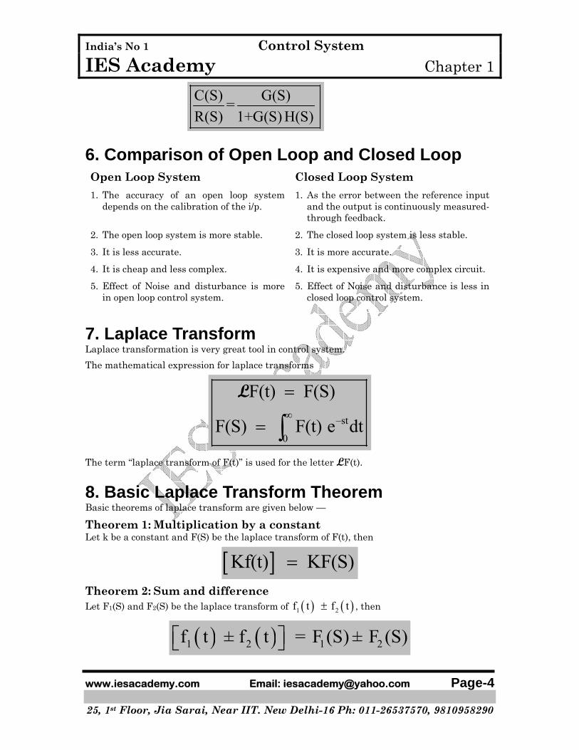
C(S) G(S)=R(S) 1+G(S) H(S)
6. Comparison of Open Loop and Closed Loop Open Loop System Closed Loop System 1. The accuracy of an open loop system
depends on the calibration of the i/p. 1. As the error between the reference input
and the output is continuously measured-through feedback.
2. The open loop system is more stable. 2. The closed loop system is less stable.
3. It is less accurate. 3. It is more accurate.
4. It is cheap and less complex. 4. It is expensive and more complex circuit.
5. Effect of Noise and disturbance is more in open loop control system.
5. Effect of Noise and disturbance is less in closed loop control system.
7. Laplace Transform Laplace transformation is very great tool in control system.
The mathematical expression for laplace transforms
–st
0
F(t) F(S)
F(S) F(t) e dt∞
=
= ∫L
The term “laplace transform of F(t)” is used for the letter LF(t).
8. Basic Laplace Transform Theorem Basic theorems of laplace transform are given below —
Theorem 1: Multiplication by a constant Let k be a constant and F(S) be the laplace transform of F(t), then
[ ]Kf(t) KF(S)=
Theorem 2: Sum and difference Let F1(S) and F2(S) be the laplace transform of ( ) ( )1 2f t f t± , then
( ) ( )1 2 1 2f t ± f t = F (S) ± F (S)⎡ ⎤⎣ ⎦

India’s No 1 Control System IES Academy Chapter 1
www.iesacademy.com Email: [email protected] Page-5 ________________________________________________________________________ 25, 1st Floor, Jia Sarai, Near IIT. New Delhi-16 Ph: 011-26537570, 9810958290
Theorem 3: Differentiation
[ ]2
2 12
dF(t)i. = SF(S) -F(0)dt
d F(t)ii. = S F(S) -F(0) -f (0)dt
⎡ ⎤⎣ ⎦
L
L
1 dF(0)where, F (0) =
dt
In general, for higher order derivatives or F(t)
1 2 (1) ( 1)( ) ( ) ( ) (0) (0)− − −⎡ ⎤= − − −⎢ ⎥
⎣ ⎦
nn n n n
n
d F t s F S s f O s f fdt
L
Where, F1(0) denotes the ith order derivative of f(t) with respect to t1,
Theorem 4: Integration
1
1 2
2 2
F(S) F (0)i. F(t) = +S S
F(S) F (0) F (0)ii. F(t) = + +S S S
⎡ ⎤⎢ ⎥⎣ ⎦⎡ ⎤⎢ ⎥⎣ ⎦
∫
∫∫
L
L
Theorem 5: Shift in time The laplace transform of F(t) delayed by time T is equal to the laplace transform F(t) multiplied by e–ST that is
[ ] -STsF(t – T) u (t – T) = e F(S)L
Where US(t–T) denotes the unit step function that is shifted in time to the right by T.
Theorem 6: Complex shifting The laplace transform of F(t) multiplied by αte∓ , where α is a constant is equal to the laplace transform F(S), with S replaced by ( )S ± α that is
αte F(t) = F(S±α)⎡ ⎤⎣ ⎦∓L
Theorem 7: Initial-value theorem If the laplace transform of F(t) is F(S), then
0lim ( ) lim ( )
→ →∞=
t SF t SF S

India’s No 1 Control System IES Academy Chapter 1
www.iesacademy.com Email: [email protected] Page-6 ________________________________________________________________________ 25, 1st Floor, Jia Sarai, Near IIT. New Delhi-16 Ph: 011-26537570, 9810958290
Theorem 8: Final value theorem
0
0
lim ( ) lim ( )
lim ( ) lim ( )t S
t S
F t S F t
F t SF S→∞ →
→∞ →
=
=
L
Point to be Remember If the denominator of SF(S) has any root having real part as zero or positive, then final value theorem is not valid. [GATE 2007]
USEFUL TRANSFORM (LAPLACE) PAIR
1 F(t) F(S) = LF(t)
2 δ(t) unit impulse 1
3 U(t) 1S
4 U(t–T) 1 steS
−
5 t 2
1S
6 2
2t
3
1S
7 nt 1n
ns +
8 ate− 1
s a+
9 ate 1
s a−
10 −atte ( )21
s a+
11 atte ( )21
−s a
12
13 –αh tt e ( ) 1/ +∠ + nn s a

India’s No 1 Control System IES Academy Chapter 1
www.iesacademy.com Email: [email protected] Page-7 ________________________________________________________________________ 25, 1st Floor, Jia Sarai, Near IIT. New Delhi-16 Ph: 011-26537570, 9810958290
14 sinωt 2 2
ωω+s
15 cosα ω− te t ( )2 2
αα ω
+
+ +
ss
16 sinα ω− te t ( )2 2
ωα ω+ +s
17 sin αh t 2 2
αα−s
18 cos αh t 2 2α−s
s
9. Summary 1. Open loop control system no feedback used. 2. In closed loop control system we used feedback. 3. Open loop system is more stable. 4. Closed loop system is more accurate. 5. Final value theorem can not used if denominators of SF(S) have real part as a zero or
positive.
India’s No 1 Control System IES Academy Chapter 1
www.iesacademy.com Email: [email protected] Page-8 ________________________________________________________________________ 25, 1st Floor, Jia Sarai, Near IIT. New Delhi-16 Ph: 011-26537570, 9810958290
ASKED OBJECTIVE QUESTIONS (GATE, IES)
Previous Years GATE Questions
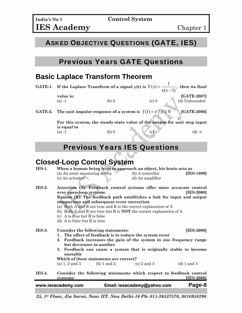
Basic Laplace Transform Theorem GATE-1. If the Laplace Transform of a signal y(t) is
1( ) ,( 1)
=−
Y ss s
then its final
value is: [GATE-2007] (a) -1 (b) 0 (c) 0 (d) Unbounded GATE-2. The unit impulse response of a system is ( ) , 0−= ≥tf t e t [GATE-2006] For this system, the steady-state value of the output for unit step input
is equal to (a) -1 (b) 0 (c) 1 (d) ∞
Previous Years IES Questions
Closed-Loop Control System IES-1. When a human being tries to approach an object, his brain acts as (a) An error measuring device (b) A controller [IES-1999] (c) An actuator (d) An amplifier IES-2. Assertion (A): Feedback control systems offer more accurate control
over open-loop systems. [IES-2000] Reason (R): The feedback path establishes a link for input and output
comparison and subsequent error correction. (a) Both A and R are true and R is the correct explanation of A (b) Both A and R are true but R is NOT the correct explanation of A (c) A is true but R is false (d) A is false but R is true IES-3. Consider the following statements: [IES-2000] 1. The effect of feedback is to reduce the system error 2. Feedback increases the gain of the system in one frequency range
but decreases in another 3. Feedback can cause a system that is originally stable to become
unstable Which of these statements are correct? (a) 1, 2 and 3 (b) 1 and 2 (c) 2 and 3 (d) 1 and 3 IES-4. Consider the following statements which respect to feedback control
systems: [IES-2006]

India’s No 1 Control System IES Academy Chapter 1
www.iesacademy.com Email: [email protected] Page-9 ________________________________________________________________________ 25, 1st Floor, Jia Sarai, Near IIT. New Delhi-16 Ph: 011-26537570, 9810958290
1. Accuracy cannot be obtained by adjusting loop gain. 2. Feedback decreases overall gain. 3. Introduction of noise due to sensor reduces overall accuracy. 4. Introduction of feedback may lead to the possibility of instability of
closed loop system. Which of the statements given above are correct? (a) 1, 2, 3 and 4 (b) Only 1, 2 and 4 (c) Only 1 and 3 (d) Only 2, 3 and 4 IES-5. A negative-feedback closed-loop system is supplied to an input of 5V.
The system has a forward gain of 1 and a feedback gain of a 1. What is the output voltage? [IES-2009]
(a) 1.0 V (b) 1.5 V (c) 2.0 V (d) 2.5 V
Basic Laplace Transform Theorem IES-6. Consider the function F(s) = 2 2s
ωω+
where F(s) is the Laplace transform
of f(t). What is the steady-state value of f(t) ? [IES-2009] (a) Zero (b) One (c) Two (d) A value between -1 and +1 IES-7. The transfer function of a linear-time-invariant system is given as
( )1
s 1+. What is the steady-state value of the unit-impulse response?
[IES-2009] (a) Zero (b) One (c) Two (d) Infinite
India’s No 1 Control System IES Academy Chapter 1
www.iesacademy.com Email: [email protected] Page-10 ________________________________________________________________________ 25, 1st Floor, Jia Sarai, Near IIT. New Delhi-16 Ph: 011-26537570, 9810958290
Answers with Explanation (Objective)
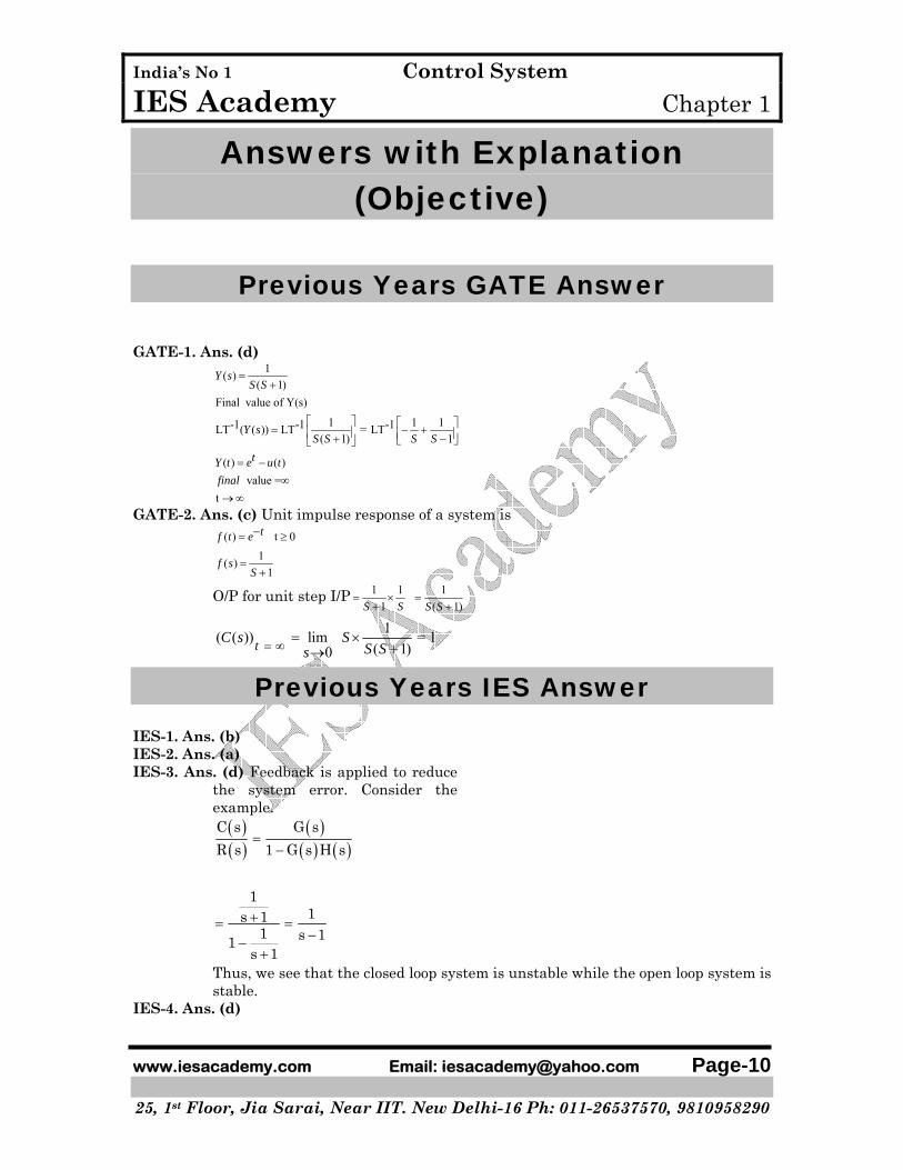
Previous Years GATE Answer GATE-1. Ans. (d)
1( )( 1)
Final value of Y(s)
1 1 1-1 -1 -1LT ( ( )) LT = LT( 1) 1
( ) ( ) value =
t
=+
⎡ ⎤ ⎡ ⎤= − +⎢ ⎥ ⎢ ⎥+ −⎣ ⎦⎣ ⎦
= −∞
→ ∞
Y sS S
Y sS S S S
tY t e u tfinal
GATE-2. Ans. (c) Unit impulse response of a system is ( ) t 0−= ≥tf t e
1( )1
=+
f sS
O/P for unit step I/P 1 11
= ×+S S
1( 1)
=+S S
1( ( )) lim = 1
( 1)0tC s SS Ss= ∞ = ×
+→
Previous Years IES Answer IES-1. Ans. (b) IES-2. Ans. (a) IES-3. Ans. (d) Feedback is applied to reduce
the system error. Consider the example.
( )( )
( )( ) ( )
C s G sR s 1 G s H s
11s 1
1 s 11s 1
=−
+= =−−
+
Thus, we see that the closed loop system is unstable while the open loop system is stable.
IES-4. Ans. (d)
India’s No 1 Control System IES Academy Chapter 1
www.iesacademy.com Email: [email protected] Page-11 ________________________________________________________________________ 25, 1st Floor, Jia Sarai, Near IIT. New Delhi-16 Ph: 011-26537570, 9810958290
IES-5. Ans. (d) Output voltage = inAV
1 AB+
( )15x 2.5V
1 1x1x= =
+
IES-6. Ans. (d) This is the Laplace transform of sin t. So, f(t) = sin t Steady-state value of f(t) is undetermined because poles of F(s) are not in LHS of s-plane. Therefore, steady-state value will vary between - 1 and + 1.
IES-7. Ans. (a) Steady state value = ( )s 0
1lims 1s 1→ +
= 0