Control Hardware Troubleshooting and Maintenance Guideftp.ruigongye.com/200805/Control.pdf · iv...
970
Experion PKS Control Hardware Troubleshooting and Maintenance Guide EP-DCX113 R210 10/04
Transcript of Control Hardware Troubleshooting and Maintenance Guideftp.ruigongye.com/200805/Control.pdf · iv...
Experion PKS
Control HardwareTroubleshooting and Maintenance
GuideEP-DCX113
R21010/04

ii Experion PKS Control Hardware Troubleshooting and Maintenance Guide R210Honeywell 10/04
Notices and Trademarks
Copyright 2004 by Honeywell International Inc.Release R210 October 25, 2004
While this information is presented in good faith and believed to be accurate, Honeywell disclaimsthe implied warranties of merchantability and fitness for a particular purpose and makes noexpress warranties except as may be stated in its written agreement with and for its customers.
In no event is Honeywell liable to anyone for any indirect, special or consequential damages. Theinformation and specifications in this document are subject to change without notice.
Honeywell, TotalPlant, and Experion PKS are registered trademarks of Honeywell InternationalInc.
Other brand or product names are trademarks of their respective owners.
Honeywell
Industry Solutions
2500 West Union Hills
Phoenix, AZ 85027
1-800 343-0228

R210 Experion PKS Control Hardware Troubleshooting and Maintenance Guide iii10/04 Honeywell
About This Document
Revision NotesThe following list provides notes concerning all revisions of this document.
Doc ID Rel ID Date Notes
EP-DCX113 R210 10/25/04 Initial Release
ReferencesThe following list identifies all documents that may be sources of reference for materialdiscussed in this publication.
Document Title Doc ID
Control Builder Error Codes Reference EP-DCX153

About This Document
iv Experion PKS Control Hardware Troubleshooting and Maintenance Guide R210Honeywell 10/04
Contacts
World Wide Web
The following lists Honeywell’s World Wide Web sites that will be of interest to ourindustrial automation and control customers.
Honeywell Organization WWW Address (URL)
Corporate http://www.honeywell.com
Automation & Control Solutions http://www.acs.honeywell.com
International http://www.honeywell.com/Business/global.asp
TelephoneContact us by telephone at the numbers listed below.
Organization Phone Number
United Statesand Canada
Honeywell International Inc.Automation & Control Solutions
1-800-223-8947 Sales416-502-5200 Canada1-800-822-7673 Tech.
Support
Asia Pacific Honeywell Ltd.Hong Kong
852-2331-9133
Europe Honeywell Ltd.Brussels, Belgium
32 2-728-2704
Latin America Honeywell International Inc.Sunrise, Florida U.S.A.
954-845-2600

About This Document
R210 Experion PKS Control Hardware Troubleshooting and Maintenance Guide v10/04 Honeywell
Symbol DefinitionsThe following table lists those symbols used in this document to denote certainconditions.
Symbol Definition
ATTENTION: Identifies information that requires specialconsideration.
TIP: Identifies advice or hints for the user, often in terms ofperforming a task.
REFERENCE -EXTERNAL: Identifies an additional source ofinformation outside of the bookset.
REFERENCE - INTERNAL: Identifies an additional source ofinformation within the bookset.
Indicates a situation which, if not avoided, may result in equipmentor work (data) on the system being damaged or lost, or may result inthe inability to properly operate the process.
CAUTION: Indicates a potentially hazardous situation which, if notavoided, may result in minor or moderate injury. It may also be usedto alert against unsafe practices.
CAUTION symbol on the equipment refers the user to the productmanual for additional information. The symbol appears next torequired information in the manual.
WARNING: Indicates a potentially hazardous situation which, if notavoided, could result in serious injury or death.
WARNING symbol on the equipment refers the user to the productmanual for additional information. The symbol appears next torequired information in the manual.
WARNING, Risk of electrical shock: Potential shock hazard whereHAZARDOUS LIVE voltages greater than 30 Vrms, 42.4 Vpeak, or60 VDC may be accessible.

About This Document
vi Experion PKS Control Hardware Troubleshooting and Maintenance Guide R210Honeywell 10/04
Symbol Definition
ESD HAZARD: Danger of an electro-static discharge to whichequipment may be sensitive. Observe precautions for handlingelectrostatic sensitive devices
Protective Earth (PE) terminal:. Provided for connection of theprotective earth (green or green/yellow) supply system conductor.
Functional earth terminal: Used for non-safety purposes such asnoise immunity improvement. NOTE: This connection shall bebonded to Protective Earth at the source of supply in accordancewith national local electrical code requirements.
Earth Ground. Functional earth connection. NOTE: Thisconnection shall be bonded to Protective Earth at the source ofsupply in accordance with national and local electrical coderequirements.
Chassis Ground: Identifies a connection to the chassis or frame ofthe equipment shall be bonded to Protective Earth at the source ofsupply in accordance with national and local electrical coderequirements.

R210 Experion PKS Control Hardware Troubleshooting and Maintenance Guide vii10/04 Honeywell
Contents
Isolating Faults.........................................................................................1Introduction .................................................................................................................. 1
Related Documentation References............................................................................ 1
To Learn More.............................................................................................................. 2
Fault Isolation............................................................................................................... 7Start .......................................................................................................................................7Module Fault ..........................................................................................................................7
BEM Fault Isolation...................................................................................................... 8Fault Isolation Table...............................................................................................................8Background............................................................................................................................8Out-Of-The-Box Assembly Required......................................................................................9Out-Of-The-Box Capacity.......................................................................................................9
CNI Fault Isolation...................................................................................................... 10CNI Not Compatible .............................................................................................................10Incorrect Keeper Values.......................................................................................................11NetworkTools Related Questions.........................................................................................11General CNI Questions ........................................................................................................12
CPM Fault Isolation.................................................................................................... 13Flash ROM Programming Errors..........................................................................................13Fault Isolation Table.............................................................................................................13
PM IOP Fault Isolation ............................................................................................... 14IOP Block Alarms and System Info Events ..........................................................................14IOP Soft Failures..................................................................................................................14IOP Box Soft failure error codes...........................................................................................16IOP Channel Soft failure error codes ...................................................................................23
RM Fault Isolation ...................................................................................................... 25
STI and STI_MV IOP Fault Isolation.......................................................................... 25Process Variable Reliability..................................................................................................26Error Detection .....................................................................................................................27Noise Immunity ....................................................................................................................28Noise Rejection ....................................................................................................................29Smart Transmitter Error Codes ............................................................................................29Smart Transmitter IOP Messages ........................................................................................31
Contents
viii Experion PKS Control Hardware Troubleshooting and Maintenance Guide R210Honeywell 10/04
Front Panel Indicators ........................................................................... 33BEM............................................................................................................................33
OK LED ............................................................................................................................... 33
CNI..............................................................................................................................34Normal Runtime Displays.................................................................................................... 34Abnormal Displays .............................................................................................................. 36Controller Redundancy Specific Displays............................................................................ 38Common questions ............................................................................................................. 40
CPM............................................................................................................................41OK LED ............................................................................................................................... 41Battery LED......................................................................................................................... 424-Character Display............................................................................................................. 43
Input Modules .............................................................................................................48
Output Modules ..........................................................................................................49
Serial Interface Modules.............................................................................................504-Character Display............................................................................................................. 50Display of Runtime Information ........................................................................................... 51Display of Failure Information.............................................................................................. 52Health Indicator ................................................................................................................... 53Channel Activity Indicators .................................................................................................. 53
RM ..............................................................................................................................54OK LED ............................................................................................................................... 54PRI LED .............................................................................................................................. 54COM LED............................................................................................................................ 554-Character Display............................................................................................................. 56
IOLIM..........................................................................................................................604-Character Display and “OK” LED ..................................................................................... 60LINK Status LEDs ............................................................................................................... 61
Fault Codes........................................................................................... 63CNI Fault Codes .........................................................................................................63
CPM Fault Codes .......................................................................................................64Background ......................................................................................................................... 640x0000 ................................................................................................................................ 640x0002 ................................................................................................................................ 640x0003 ................................................................................................................................ 640x0004 ................................................................................................................................ 650x0006 ................................................................................................................................ 650x0007 ................................................................................................................................ 650x0008 ................................................................................................................................ 65

Contents
R210 Experion PKS Control Hardware Troubleshooting and Maintenance Guide ix10/04 Honeywell
0x000D.................................................................................................................................660x0013 .................................................................................................................................660x0014 .................................................................................................................................660x0401 .................................................................................................................................660x0402 .................................................................................................................................670x0403 .................................................................................................................................670x0404 .................................................................................................................................670x0405 .................................................................................................................................670x0406 .................................................................................................................................680x0407 .................................................................................................................................680x0408 .................................................................................................................................680x0409 .................................................................................................................................680x040A.................................................................................................................................690x040B.................................................................................................................................690x040C.................................................................................................................................690x040D.................................................................................................................................690x040E.................................................................................................................................700x040F .................................................................................................................................700x0410 .................................................................................................................................700x0411 .................................................................................................................................700x0412 .................................................................................................................................710x0413 .................................................................................................................................710x0414 .................................................................................................................................710x0415 .................................................................................................................................710x0416 .................................................................................................................................720x0417 .................................................................................................................................720x0418 .................................................................................................................................720x0419 .................................................................................................................................720x041A.................................................................................................................................730x041B.................................................................................................................................730x041C.................................................................................................................................730x041D.................................................................................................................................730x041E.................................................................................................................................740x041F .................................................................................................................................740x0420 .................................................................................................................................740x0421 .................................................................................................................................740x0422 .................................................................................................................................750x0423 .................................................................................................................................750x0424 .................................................................................................................................750x0425 .................................................................................................................................750x0426 .................................................................................................................................760x0427 .................................................................................................................................760x0428 .................................................................................................................................760x0429 .................................................................................................................................760x042A.................................................................................................................................770x042B.................................................................................................................................770x042C.................................................................................................................................770x042D.................................................................................................................................770x042E.................................................................................................................................78

Contents
x Experion PKS Control Hardware Troubleshooting and Maintenance Guide R210Honeywell 10/04
0x042F ................................................................................................................................ 780x0430 ................................................................................................................................ 780x0431 ................................................................................................................................ 78
Exchange Block ERRCODE Fault Codes ..................................................................78Description .......................................................................................................................... 791 .......................................................................................................................................... 792 .......................................................................................................................................... 793 .......................................................................................................................................... 804 .......................................................................................................................................... 805 .......................................................................................................................................... 818 .......................................................................................................................................... 8112 ........................................................................................................................................ 8114 ........................................................................................................................................ 8115 ........................................................................................................................................ 8217 ........................................................................................................................................ 8219 ........................................................................................................................................ 8221 ........................................................................................................................................ 8231 ........................................................................................................................................ 8334 ........................................................................................................................................ 83255 ...................................................................................................................................... 83512 ...................................................................................................................................... 83768 ...................................................................................................................................... 841024 .................................................................................................................................... 841280 .................................................................................................................................... 841536 .................................................................................................................................... 841792 .................................................................................................................................... 842010 .................................................................................................................................... 852047 .................................................................................................................................... 852048 .................................................................................................................................... 852089 .................................................................................................................................... 852304 .................................................................................................................................... 862560 .................................................................................................................................... 864096 .................................................................................................................................... 868192 .................................................................................................................................... 8612288 .................................................................................................................................. 8716384 .................................................................................................................................. 8720480 .................................................................................................................................. 8724576 .................................................................................................................................. 8728672 .................................................................................................................................. 8732768 .................................................................................................................................. 8836864 .................................................................................................................................. 8845056 .................................................................................................................................. 8849152 .................................................................................................................................. 8853248 .................................................................................................................................. 8861441 .................................................................................................................................. 8961442 .................................................................................................................................. 8961443 .................................................................................................................................. 8961444 .................................................................................................................................. 90

Contents
R210 Experion PKS Control Hardware Troubleshooting and Maintenance Guide xi10/04 Honeywell
61445 ...................................................................................................................................9061446 ...................................................................................................................................9061447 ...................................................................................................................................9161448 ...................................................................................................................................9161449 ...................................................................................................................................9161450 ...................................................................................................................................9161451 ...................................................................................................................................9261452 ...................................................................................................................................9261453 ...................................................................................................................................9261454 ...................................................................................................................................9261455 ...................................................................................................................................9261456 ...................................................................................................................................9361457 ...................................................................................................................................9361458 ...................................................................................................................................9361459 ...................................................................................................................................9361460 ...................................................................................................................................9361461 ...................................................................................................................................9461462 ...................................................................................................................................9461463 ...................................................................................................................................9461464 ...................................................................................................................................9461465 ...................................................................................................................................9561466 ...................................................................................................................................9561467 ...................................................................................................................................9561468 ...................................................................................................................................9561469 ...................................................................................................................................9561470 ...................................................................................................................................9661471 ...................................................................................................................................96
I/O Fault Codes .......................................................................................................... 97TC-ODX081 Discrete AC Output Module.............................................................................97
RM Fault Codes ......................................................................................................... 98About fault code format ........................................................................................................98E000.....................................................................................................................................99E001.....................................................................................................................................99E010...................................................................................................................................100E020...................................................................................................................................100E021...................................................................................................................................100E022...................................................................................................................................100E023...................................................................................................................................101E024...................................................................................................................................101E025...................................................................................................................................101E026...................................................................................................................................101E027...................................................................................................................................102E028...................................................................................................................................102E029...................................................................................................................................102E02A ..................................................................................................................................102E02B ..................................................................................................................................103E02C ..................................................................................................................................103

Contents
xii Experion PKS Control Hardware Troubleshooting and Maintenance Guide R210Honeywell 10/04
E02D ................................................................................................................................. 103E030.................................................................................................................................. 103E031.................................................................................................................................. 104E032.................................................................................................................................. 104E033.................................................................................................................................. 104E034.................................................................................................................................. 104E035.................................................................................................................................. 105E036.................................................................................................................................. 105E037.................................................................................................................................. 105E038.................................................................................................................................. 105E039.................................................................................................................................. 106E03A ................................................................................................................................. 106E03a.................................................................................................................................. 106E03B ................................................................................................................................. 106E03b.................................................................................................................................. 107E03C ................................................................................................................................. 107E03D ................................................................................................................................. 107E03E ................................................................................................................................. 107E03F.................................................................................................................................. 108E03G ................................................................................................................................. 108E03H ................................................................................................................................. 108E03I................................................................................................................................... 108E03J .................................................................................................................................. 109E03K ................................................................................................................................. 109E03L.................................................................................................................................. 109E03M................................................................................................................................. 109E03N ................................................................................................................................. 110E03P ................................................................................................................................. 110E03Q ................................................................................................................................. 110E03R ................................................................................................................................. 110E03T.................................................................................................................................. 111E03U ................................................................................................................................. 111E03V ................................................................................................................................. 111E03W ................................................................................................................................ 111E03X ................................................................................................................................. 112E03Y ................................................................................................................................. 112E03Z.................................................................................................................................. 112E040.................................................................................................................................. 112E041.................................................................................................................................. 113E042.................................................................................................................................. 113E043.................................................................................................................................. 113E044.................................................................................................................................. 113E045.................................................................................................................................. 114E046.................................................................................................................................. 114E047.................................................................................................................................. 114E048.................................................................................................................................. 114E049.................................................................................................................................. 115E04A ................................................................................................................................. 115E04B ................................................................................................................................. 115

Contents
R210 Experion PKS Control Hardware Troubleshooting and Maintenance Guide xiii10/04 Honeywell
E04C ..................................................................................................................................115E04D ..................................................................................................................................116E050...................................................................................................................................116E051...................................................................................................................................116E052...................................................................................................................................116E053...................................................................................................................................117E054...................................................................................................................................117E060...................................................................................................................................118E07A ..................................................................................................................................118E070...................................................................................................................................118E071...................................................................................................................................118E072...................................................................................................................................118E073...................................................................................................................................119E074...................................................................................................................................119E075...................................................................................................................................119E076...................................................................................................................................119E077...................................................................................................................................119E078...................................................................................................................................120E079...................................................................................................................................120E080...................................................................................................................................120E090...................................................................................................................................120E091...................................................................................................................................121E092...................................................................................................................................121E093...................................................................................................................................121E0A0 ..................................................................................................................................121E0A1 ..................................................................................................................................122E0A2 ..................................................................................................................................122E0A3 ..................................................................................................................................122E0A4 ..................................................................................................................................122E0A5 ..................................................................................................................................123E0A6 ..................................................................................................................................123E0A7 ..................................................................................................................................123E0A8 ..................................................................................................................................123E0B0 ..................................................................................................................................124E0B1 ..................................................................................................................................124E0B2 ..................................................................................................................................124E0C0 ..................................................................................................................................124E0C1 ..................................................................................................................................125E0C2 ..................................................................................................................................125E0C3 ..................................................................................................................................125E0C4 ..................................................................................................................................126E0C5 ..................................................................................................................................126E0D0 ..................................................................................................................................126E0D1 ..................................................................................................................................126E0D2 ..................................................................................................................................127E0D3 ..................................................................................................................................127E0D4 ..................................................................................................................................127E0D5 ..................................................................................................................................127E0D6 ..................................................................................................................................127
Contents
xiv Experion PKS Control Hardware Troubleshooting and Maintenance Guide R210Honeywell 10/04
E0D7 ................................................................................................................................. 128E0D8 ................................................................................................................................. 128E0D9 ................................................................................................................................. 128E0DA................................................................................................................................. 128E0DB................................................................................................................................. 128E0DC................................................................................................................................. 129E0E0 ................................................................................................................................. 129E0E1 ................................................................................................................................. 129E0E2 ................................................................................................................................. 129E0F0.................................................................................................................................. 130E0G0 ................................................................................................................................. 130E0H0 ................................................................................................................................. 130E0I0................................................................................................................................... 130E0I1................................................................................................................................... 131E0I2................................................................................................................................... 131E0I3................................................................................................................................... 131E0I4................................................................................................................................... 131E0I5................................................................................................................................... 132E0I6................................................................................................................................... 132E0I7................................................................................................................................... 132E0I8................................................................................................................................... 132E0I9................................................................................................................................... 133E0IA .................................................................................................................................. 133E0IB .................................................................................................................................. 133E0IC .................................................................................................................................. 133E0ID .................................................................................................................................. 134E0IE .................................................................................................................................. 134E0IF................................................................................................................................... 134E0IG .................................................................................................................................. 134E0J0 .................................................................................................................................. 135E101.................................................................................................................................. 135E102.................................................................................................................................. 135E103.................................................................................................................................. 135E104.................................................................................................................................. 136E105.................................................................................................................................. 136E106.................................................................................................................................. 136E107.................................................................................................................................. 136E108.................................................................................................................................. 136E109.................................................................................................................................. 137E10A ................................................................................................................................. 137E10B ................................................................................................................................. 137E10C ................................................................................................................................. 137E10D ................................................................................................................................. 137E10E ................................................................................................................................. 138E10F.................................................................................................................................. 138E10G ................................................................................................................................. 138E10H ................................................................................................................................. 138E10I................................................................................................................................... 138E10J .................................................................................................................................. 139

Contents
R210 Experion PKS Control Hardware Troubleshooting and Maintenance Guide xv10/04 Honeywell
E10K ..................................................................................................................................139E10L...................................................................................................................................139E10M..................................................................................................................................139E10N ..................................................................................................................................139E10P ..................................................................................................................................140E201...................................................................................................................................140E202...................................................................................................................................140E203...................................................................................................................................140E204...................................................................................................................................141E205...................................................................................................................................141E206...................................................................................................................................141E207...................................................................................................................................141E208...................................................................................................................................141E209...................................................................................................................................142E20A ..................................................................................................................................142E20B ..................................................................................................................................142E20C ..................................................................................................................................142E20D ..................................................................................................................................143E20E ..................................................................................................................................143E20F ..................................................................................................................................143E20G..................................................................................................................................143E20H ..................................................................................................................................144E20I....................................................................................................................................144E20J...................................................................................................................................144E20K ..................................................................................................................................144E20L...................................................................................................................................145E20M..................................................................................................................................145E210...................................................................................................................................145E211...................................................................................................................................145E230...................................................................................................................................146E235...................................................................................................................................146E236...................................................................................................................................146E237...................................................................................................................................146E239...................................................................................................................................147E23B ..................................................................................................................................147E250...................................................................................................................................147E251...................................................................................................................................147E252...................................................................................................................................148E253...................................................................................................................................148E254...................................................................................................................................148E255...................................................................................................................................148E256...................................................................................................................................148E257...................................................................................................................................149E258...................................................................................................................................149E259...................................................................................................................................149E25A ..................................................................................................................................149E25B ..................................................................................................................................149E25C ..................................................................................................................................150E25D ..................................................................................................................................150
Contents
xvi Experion PKS Control Hardware Troubleshooting and Maintenance Guide R210Honeywell 10/04
E25E ................................................................................................................................. 150E25F.................................................................................................................................. 150E25G ................................................................................................................................. 150E25H ................................................................................................................................. 151E25I................................................................................................................................... 151E25J .................................................................................................................................. 151E260.................................................................................................................................. 151E261.................................................................................................................................. 152E262.................................................................................................................................. 152E263.................................................................................................................................. 152E264.................................................................................................................................. 152E265.................................................................................................................................. 153E266.................................................................................................................................. 153E267.................................................................................................................................. 153E268.................................................................................................................................. 153E269.................................................................................................................................. 154E26A ................................................................................................................................. 154E26B ................................................................................................................................. 154E270.................................................................................................................................. 154E271.................................................................................................................................. 155E280.................................................................................................................................. 155E281.................................................................................................................................. 155E282.................................................................................................................................. 155E283.................................................................................................................................. 156E284.................................................................................................................................. 156E285.................................................................................................................................. 156E288.................................................................................................................................. 156E289.................................................................................................................................. 157E28A ................................................................................................................................. 157E28B ................................................................................................................................. 157E28C ................................................................................................................................. 157E28D ................................................................................................................................. 158E290.................................................................................................................................. 158E291.................................................................................................................................. 158E292.................................................................................................................................. 158E293.................................................................................................................................. 159E294.................................................................................................................................. 159E295.................................................................................................................................. 159E296.................................................................................................................................. 159E297.................................................................................................................................. 160E298.................................................................................................................................. 160E299.................................................................................................................................. 160E2B0 ................................................................................................................................. 160E2B1 ................................................................................................................................. 161E2B2 ................................................................................................................................. 161E2B3 ................................................................................................................................. 161E2B4 ................................................................................................................................. 161E2B5 ................................................................................................................................. 161E2B6 ................................................................................................................................. 162
Contents
R210 Experion PKS Control Hardware Troubleshooting and Maintenance Guide xvii10/04 Honeywell
E2B7 ..................................................................................................................................162E2B8 ..................................................................................................................................162E2B9 ..................................................................................................................................162E2BA..................................................................................................................................163E2BB..................................................................................................................................163E2BC..................................................................................................................................163E2BD..................................................................................................................................163E2BE..................................................................................................................................163E2BF ..................................................................................................................................164E2BG .................................................................................................................................164E2BH..................................................................................................................................164E2BI ...................................................................................................................................164E2BJ ..................................................................................................................................165E2BK..................................................................................................................................165E2BL ..................................................................................................................................165E2C0 ..................................................................................................................................165E2C1 ..................................................................................................................................165E2C2 ..................................................................................................................................166E2C3 ..................................................................................................................................166E2C4 ..................................................................................................................................166E2C5 ..................................................................................................................................166E2C6 ..................................................................................................................................166E2C7 ..................................................................................................................................167E2C8 ..................................................................................................................................167E2C9 ..................................................................................................................................167E2CA..................................................................................................................................167E2CB..................................................................................................................................168E2CC..................................................................................................................................168E2CD..................................................................................................................................168E2CE..................................................................................................................................168E2CF..................................................................................................................................169E2CG .................................................................................................................................169E2CH..................................................................................................................................169E2CI ...................................................................................................................................169E2CJ ..................................................................................................................................170E2CK..................................................................................................................................170E2CL ..................................................................................................................................170E2D0 ..................................................................................................................................170E2E0 ..................................................................................................................................170E2E1 ..................................................................................................................................171E2E2 ..................................................................................................................................171E2E3 ..................................................................................................................................171E2E4 ..................................................................................................................................171E2E5 ..................................................................................................................................172E2E6 ..................................................................................................................................172E2E7 ..................................................................................................................................172E2E8 ..................................................................................................................................172E2E9 ..................................................................................................................................173E2EA..................................................................................................................................173

Contents
xviii Experion PKS Control Hardware Troubleshooting and Maintenance Guide R210Honeywell 10/04
E2EB ................................................................................................................................. 173E2EC................................................................................................................................. 173E2ED................................................................................................................................. 174E2EE ................................................................................................................................. 174E2EF ................................................................................................................................. 174E2EG................................................................................................................................. 174E2EH................................................................................................................................. 175E2F0.................................................................................................................................. 175E2F1.................................................................................................................................. 175E2F2.................................................................................................................................. 175E2F3.................................................................................................................................. 176E2F4.................................................................................................................................. 176E2F5.................................................................................................................................. 176E2F6.................................................................................................................................. 176E2F7.................................................................................................................................. 177E2F8.................................................................................................................................. 177E2F9.................................................................................................................................. 177E2FA ................................................................................................................................. 177E2FB ................................................................................................................................. 178E2FC ................................................................................................................................. 178E2FD ................................................................................................................................. 178E2FE ................................................................................................................................. 178E2FF ................................................................................................................................. 179E2G0 ................................................................................................................................. 179E2G1 ................................................................................................................................. 179E2H0 ................................................................................................................................. 179E2H1 ................................................................................................................................. 180E2J0 .................................................................................................................................. 180E2J1 .................................................................................................................................. 180E2J2 .................................................................................................................................. 180E2J3 .................................................................................................................................. 181E2J4 .................................................................................................................................. 181E2J5 .................................................................................................................................. 181E2J6 .................................................................................................................................. 181E2J7 .................................................................................................................................. 182E2J8 .................................................................................................................................. 182E2J9 .................................................................................................................................. 182E2K0 ................................................................................................................................. 182E2L0.................................................................................................................................. 183E2L1.................................................................................................................................. 183E2M0................................................................................................................................. 183E2M1................................................................................................................................. 183E2N0 ................................................................................................................................. 184E2P0 ................................................................................................................................. 184E2Q0 ................................................................................................................................. 184E2Q1 ................................................................................................................................. 184E2Q2 ................................................................................................................................. 185E2Q3 ................................................................................................................................. 185E2Q4 ................................................................................................................................. 185

Contents
R210 Experion PKS Control Hardware Troubleshooting and Maintenance Guide xix10/04 Honeywell
E2Q5..................................................................................................................................185E2Q6..................................................................................................................................186E2Q7..................................................................................................................................186E2Q8..................................................................................................................................186E2Q9..................................................................................................................................186E2QA .................................................................................................................................187E2QB .................................................................................................................................187E2QC .................................................................................................................................187E2QD .................................................................................................................................187E2QE .................................................................................................................................188E2QF..................................................................................................................................188E300...................................................................................................................................188E301...................................................................................................................................188E400...................................................................................................................................189E401...................................................................................................................................189E402...................................................................................................................................189E404...................................................................................................................................189E405...................................................................................................................................189E406...................................................................................................................................190E407...................................................................................................................................190E408...................................................................................................................................190E409...................................................................................................................................190E40A ..................................................................................................................................191E410...................................................................................................................................191E420...................................................................................................................................191E430...................................................................................................................................191E440...................................................................................................................................192E450...................................................................................................................................192E451...................................................................................................................................192E460...................................................................................................................................192E470...................................................................................................................................192E480...................................................................................................................................193E481...................................................................................................................................193E490...................................................................................................................................193E4A0 ..................................................................................................................................193E4B0 ..................................................................................................................................193E4C0 ..................................................................................................................................194E4D0 ..................................................................................................................................194E4E0 ..................................................................................................................................194E4F0 ..................................................................................................................................194E4G0..................................................................................................................................194E4H0 ..................................................................................................................................195E4I0....................................................................................................................................195E4J0...................................................................................................................................195E4K0 ..................................................................................................................................195E4L0...................................................................................................................................195E4L1...................................................................................................................................196E4L2...................................................................................................................................196E4M0..................................................................................................................................196

Contents
xx Experion PKS Control Hardware Troubleshooting and Maintenance Guide R210Honeywell 10/04
E4N0 ................................................................................................................................. 196E4N1 ................................................................................................................................. 196E4P0 ................................................................................................................................. 197E4P1 ................................................................................................................................. 197E4P2 ................................................................................................................................. 197E4P3 ................................................................................................................................. 197E4P4 ................................................................................................................................. 198E4Q0 ................................................................................................................................. 198E4R0 ................................................................................................................................. 198E4T0.................................................................................................................................. 198E4U0 ................................................................................................................................. 198E4U1 ................................................................................................................................. 199E4U2 ................................................................................................................................. 199E4U3 ................................................................................................................................. 199E4V0 ................................................................................................................................. 199E4V3 ................................................................................................................................. 199E4V4 ................................................................................................................................. 200E4V5 ................................................................................................................................. 200E4V6 ................................................................................................................................. 200E4V7 ................................................................................................................................. 200E4V8 ................................................................................................................................. 201E4V9 ................................................................................................................................. 201E4VA ................................................................................................................................. 201E4VB ................................................................................................................................. 201E4VC................................................................................................................................. 202E4VD................................................................................................................................. 202E4VE ................................................................................................................................. 202E4VF ................................................................................................................................. 202E4VG................................................................................................................................. 202E4VH................................................................................................................................. 203E4VI .................................................................................................................................. 203E4W0 ................................................................................................................................ 203E4X0 ................................................................................................................................. 203E4X1 ................................................................................................................................. 204E4X2 ................................................................................................................................. 204E500.................................................................................................................................. 204E600.................................................................................................................................. 204E601.................................................................................................................................. 205E602.................................................................................................................................. 205E603.................................................................................................................................. 205E604.................................................................................................................................. 205E605.................................................................................................................................. 206E606.................................................................................................................................. 206E607.................................................................................................................................. 206E608.................................................................................................................................. 206E609.................................................................................................................................. 207E610.................................................................................................................................. 207E611.................................................................................................................................. 207E612.................................................................................................................................. 207

Contents
R210 Experion PKS Control Hardware Troubleshooting and Maintenance Guide xxi10/04 Honeywell
E614...................................................................................................................................208E615...................................................................................................................................208E631...................................................................................................................................208E640...................................................................................................................................208E641...................................................................................................................................209E642...................................................................................................................................209E643...................................................................................................................................209E644...................................................................................................................................209E645...................................................................................................................................210E646...................................................................................................................................210E647...................................................................................................................................210E648...................................................................................................................................210E649...................................................................................................................................211E650...................................................................................................................................211E651...................................................................................................................................211E652...................................................................................................................................211E653...................................................................................................................................212E654...................................................................................................................................212E655...................................................................................................................................212E656...................................................................................................................................212E660...................................................................................................................................213E670...................................................................................................................................213E671...................................................................................................................................213E672...................................................................................................................................213E673...................................................................................................................................214E680...................................................................................................................................214E690...................................................................................................................................214E6A0 ..................................................................................................................................214E6B0 ..................................................................................................................................215E6C0 ..................................................................................................................................215E6C1 ..................................................................................................................................215E6C2 ..................................................................................................................................215E6C3 ..................................................................................................................................216E6C4 ..................................................................................................................................216E6C5 ..................................................................................................................................216E6C6 ..................................................................................................................................216E6C7 ..................................................................................................................................217E6C8 ..................................................................................................................................217E6C9 ..................................................................................................................................217E6CA..................................................................................................................................217E6CB..................................................................................................................................218E6CC..................................................................................................................................218E6CD..................................................................................................................................218E6D0 ..................................................................................................................................218E6D1 ..................................................................................................................................219E6D2 ..................................................................................................................................219E6D3 ..................................................................................................................................219E6D4 ..................................................................................................................................219E6E0 ..................................................................................................................................220

Contents
xxii Experion PKS Control Hardware Troubleshooting and Maintenance Guide R210Honeywell 10/04
E6F0.................................................................................................................................. 220E700.................................................................................................................................. 220E701.................................................................................................................................. 220E702.................................................................................................................................. 221E703.................................................................................................................................. 221E704.................................................................................................................................. 221E70E ................................................................................................................................. 221E70G ................................................................................................................................. 222E70H ................................................................................................................................. 222E70L.................................................................................................................................. 222E70N ................................................................................................................................. 222E70Q ................................................................................................................................. 223E70T.................................................................................................................................. 223E70U ................................................................................................................................. 223E70V ................................................................................................................................. 223E70W ................................................................................................................................ 224E710.................................................................................................................................. 224E711.................................................................................................................................. 224E712.................................................................................................................................. 224E713.................................................................................................................................. 225E714.................................................................................................................................. 225E715.................................................................................................................................. 225E716.................................................................................................................................. 225E717.................................................................................................................................. 226E718.................................................................................................................................. 226E719.................................................................................................................................. 226E71A ................................................................................................................................. 226E71B ................................................................................................................................. 227E71C ................................................................................................................................. 227E71D ................................................................................................................................. 227E71E ................................................................................................................................. 227E71F.................................................................................................................................. 228E71G ................................................................................................................................. 228E71H ................................................................................................................................. 228E71I................................................................................................................................... 228E71J .................................................................................................................................. 228E720.................................................................................................................................. 229E721.................................................................................................................................. 229E722.................................................................................................................................. 229E723.................................................................................................................................. 229E724.................................................................................................................................. 230E725.................................................................................................................................. 230E726.................................................................................................................................. 230E727.................................................................................................................................. 230E728.................................................................................................................................. 231E729.................................................................................................................................. 231E72A ................................................................................................................................. 231E72B ................................................................................................................................. 231E72C ................................................................................................................................. 231
Contents
R210 Experion PKS Control Hardware Troubleshooting and Maintenance Guide xxiii10/04 Honeywell
E72D ..................................................................................................................................232E730...................................................................................................................................232E731...................................................................................................................................232E732...................................................................................................................................232E733...................................................................................................................................232E734...................................................................................................................................233E735...................................................................................................................................233E736...................................................................................................................................233E737...................................................................................................................................234E738...................................................................................................................................234E739...................................................................................................................................234E73A ..................................................................................................................................234E73C ..................................................................................................................................235E73D ..................................................................................................................................235E73F ..................................................................................................................................235E73G..................................................................................................................................235E73H ..................................................................................................................................236E73I....................................................................................................................................236E740...................................................................................................................................236E741...................................................................................................................................236E742...................................................................................................................................237E752...................................................................................................................................237E753...................................................................................................................................237E754...................................................................................................................................237E755...................................................................................................................................238E756...................................................................................................................................238E757...................................................................................................................................238E75A ..................................................................................................................................238E75B ..................................................................................................................................239E75C ..................................................................................................................................239E75D ..................................................................................................................................239E75E ..................................................................................................................................239E75F ..................................................................................................................................240E75G..................................................................................................................................240E75I....................................................................................................................................240E75J...................................................................................................................................240E75K ..................................................................................................................................241E75L...................................................................................................................................241E75M..................................................................................................................................241E760...................................................................................................................................241E762...................................................................................................................................242E763...................................................................................................................................242E764...................................................................................................................................242E766...................................................................................................................................242E767...................................................................................................................................243E768...................................................................................................................................243E769...................................................................................................................................243E76A ..................................................................................................................................243E76C ..................................................................................................................................244

Contents
xxiv Experion PKS Control Hardware Troubleshooting and Maintenance Guide R210Honeywell 10/04
E76D ................................................................................................................................. 244E76E ................................................................................................................................. 244E76F.................................................................................................................................. 244E770.................................................................................................................................. 245E771.................................................................................................................................. 245E772.................................................................................................................................. 245E774.................................................................................................................................. 245E777.................................................................................................................................. 246E778.................................................................................................................................. 246E779.................................................................................................................................. 246E77A ................................................................................................................................. 246E77C ................................................................................................................................. 247E77E ................................................................................................................................. 247E77H ................................................................................................................................. 247E77I................................................................................................................................... 247E77J .................................................................................................................................. 248E77K ................................................................................................................................. 248E790.................................................................................................................................. 248E791.................................................................................................................................. 248E792.................................................................................................................................. 249E7B1 ................................................................................................................................. 249E7B2 ................................................................................................................................. 249E7B3 ................................................................................................................................. 249E7B4 ................................................................................................................................. 250E7B6 ................................................................................................................................. 250E7B7 ................................................................................................................................. 250E7B8 ................................................................................................................................. 250E7B9 ................................................................................................................................. 251E7BA ................................................................................................................................. 251E7BB ................................................................................................................................. 251E7BC................................................................................................................................. 251E7BD................................................................................................................................. 252E7BE ................................................................................................................................. 252E7BF ................................................................................................................................. 252E7BG................................................................................................................................. 252E7BH................................................................................................................................. 253E7BI .................................................................................................................................. 253E7BJ.................................................................................................................................. 253E7BL ................................................................................................................................. 253E7BM ................................................................................................................................ 254E7BN................................................................................................................................. 254E7BQ................................................................................................................................. 254E7BT ................................................................................................................................. 254E7BU................................................................................................................................. 255E800.................................................................................................................................. 255E801.................................................................................................................................. 255E810.................................................................................................................................. 255E811.................................................................................................................................. 256E812.................................................................................................................................. 256

Contents
R210 Experion PKS Control Hardware Troubleshooting and Maintenance Guide xxv10/04 Honeywell
E813...................................................................................................................................256E814...................................................................................................................................256E815...................................................................................................................................257E816...................................................................................................................................257E817...................................................................................................................................257E818...................................................................................................................................257E819...................................................................................................................................258E81A ..................................................................................................................................258E81B ..................................................................................................................................258E81C ..................................................................................................................................258E81D ..................................................................................................................................259E81E ..................................................................................................................................259E820...................................................................................................................................259E821...................................................................................................................................259E830...................................................................................................................................260E831...................................................................................................................................260E832...................................................................................................................................260E833...................................................................................................................................260E834...................................................................................................................................260E835...................................................................................................................................261E836...................................................................................................................................261E840...................................................................................................................................261E841...................................................................................................................................261E850...................................................................................................................................262E851...................................................................................................................................262E852...................................................................................................................................262E860...................................................................................................................................262E861...................................................................................................................................262E862...................................................................................................................................263E870...................................................................................................................................263E871...................................................................................................................................263E872...................................................................................................................................263E873...................................................................................................................................263E876...................................................................................................................................264E880...................................................................................................................................264E881...................................................................................................................................264E882...................................................................................................................................264E883...................................................................................................................................264E884...................................................................................................................................265E885...................................................................................................................................265E886...................................................................................................................................265E887...................................................................................................................................265E888...................................................................................................................................266E889...................................................................................................................................266E88A ..................................................................................................................................266E88B ..................................................................................................................................266E88C ..................................................................................................................................267E88D ..................................................................................................................................267E88E ..................................................................................................................................267
Contents
xxvi Experion PKS Control Hardware Troubleshooting and Maintenance Guide R210Honeywell 10/04
E891.................................................................................................................................. 267E892.................................................................................................................................. 268E893.................................................................................................................................. 268E894.................................................................................................................................. 268E895.................................................................................................................................. 268E896.................................................................................................................................. 269E8A0 ................................................................................................................................. 269E8A1 ................................................................................................................................. 269E8A2 ................................................................................................................................. 269E8A3 ................................................................................................................................. 270E8A4 ................................................................................................................................. 270E8A5 ................................................................................................................................. 270E8B0 ................................................................................................................................. 270EA00 ................................................................................................................................. 270EA01 ................................................................................................................................. 271EA02 ................................................................................................................................. 271EA03 ................................................................................................................................. 271EA04 ................................................................................................................................. 271EA05 ................................................................................................................................. 271EA10 ................................................................................................................................. 272EA11 ................................................................................................................................. 272EA12 ................................................................................................................................. 272EA13 ................................................................................................................................. 272EA14 ................................................................................................................................. 272EA15 ................................................................................................................................. 273EA16 ................................................................................................................................. 273EA17 ................................................................................................................................. 273EA18 ................................................................................................................................. 273EA19 ................................................................................................................................. 273EA1B ................................................................................................................................. 274EA1C................................................................................................................................. 274EA1D................................................................................................................................. 274EA1E ................................................................................................................................. 274EA1F ................................................................................................................................. 274EA1G................................................................................................................................. 275EA1H................................................................................................................................. 275EA1I .................................................................................................................................. 275EA1J.................................................................................................................................. 275EA1K ................................................................................................................................. 275EA1L ................................................................................................................................. 276EA1M ................................................................................................................................ 276EA1N................................................................................................................................. 276EA1P ................................................................................................................................. 276EA1Q................................................................................................................................. 276EA1R................................................................................................................................. 277EA1T ................................................................................................................................. 277EA1U................................................................................................................................. 277EA1V ................................................................................................................................. 277EA1W ................................................................................................................................ 278
Contents
R210 Experion PKS Control Hardware Troubleshooting and Maintenance Guide xxvii10/04 Honeywell
EA20 ..................................................................................................................................278EA21 ..................................................................................................................................278EA22 ..................................................................................................................................278EA23 ..................................................................................................................................279EA24 ..................................................................................................................................279EA25 ..................................................................................................................................279EA26 ..................................................................................................................................279EA27 ..................................................................................................................................279EA28 ..................................................................................................................................280EA29 ..................................................................................................................................280EA2A..................................................................................................................................280EA2B..................................................................................................................................280EA2C..................................................................................................................................281EA2E..................................................................................................................................281EA2F ..................................................................................................................................281EA2G .................................................................................................................................281EA2H..................................................................................................................................282EA2I ...................................................................................................................................282EA2J ..................................................................................................................................282EA2K..................................................................................................................................282EA2L ..................................................................................................................................283EA2M .................................................................................................................................283EA30 ..................................................................................................................................283EA31 ..................................................................................................................................283EA32 ..................................................................................................................................283EA33 ..................................................................................................................................284EA34 ..................................................................................................................................284EA35 ..................................................................................................................................284EA36 ..................................................................................................................................284EA37 ..................................................................................................................................285EA38 ..................................................................................................................................285EA39 ..................................................................................................................................285EA3A..................................................................................................................................285EA3B..................................................................................................................................285EA3C..................................................................................................................................286EA3D..................................................................................................................................286EA3E..................................................................................................................................286EA3F ..................................................................................................................................286EA3G .................................................................................................................................286EA3H..................................................................................................................................287EA3I ...................................................................................................................................287EA3J ..................................................................................................................................287EA3K..................................................................................................................................287EA3L ..................................................................................................................................288EA3N..................................................................................................................................288EA3P..................................................................................................................................288EA3Q .................................................................................................................................288EA3R..................................................................................................................................289EA3T ..................................................................................................................................289

Contents
xxviii Experion PKS Control Hardware Troubleshooting and Maintenance Guide R210Honeywell 10/04
EA3U................................................................................................................................. 289EA3V ................................................................................................................................. 289EA40 ................................................................................................................................. 289EA41 ................................................................................................................................. 290EA42 ................................................................................................................................. 290EA43 ................................................................................................................................. 290EA44 ................................................................................................................................. 290EA45 ................................................................................................................................. 290EA46 ................................................................................................................................. 291EA47 ................................................................................................................................. 291EA48 ................................................................................................................................. 291EA49 ................................................................................................................................. 291EA4A ................................................................................................................................. 291EA4B ................................................................................................................................. 292EA4C................................................................................................................................. 292EA4E ................................................................................................................................. 292EA4F ................................................................................................................................. 292EA4G................................................................................................................................. 293EA4H................................................................................................................................. 293EA4I .................................................................................................................................. 293EA4J.................................................................................................................................. 293EA4K ................................................................................................................................. 293EA4L ................................................................................................................................. 294EA4M ................................................................................................................................ 294EA50 ................................................................................................................................. 294EA51 ................................................................................................................................. 294EA52 ................................................................................................................................. 294EA53 ................................................................................................................................. 295EA54 ................................................................................................................................. 295EA55 ................................................................................................................................. 295EA56 ................................................................................................................................. 295EA57 ................................................................................................................................. 295EA58 ................................................................................................................................. 296EA59 ................................................................................................................................. 296EA5A ................................................................................................................................. 296EA5B ................................................................................................................................. 296EA5D................................................................................................................................. 297EA5E ................................................................................................................................. 297EA5F ................................................................................................................................. 297EA5G................................................................................................................................. 297EA5H................................................................................................................................. 297EA5I .................................................................................................................................. 298EA5J.................................................................................................................................. 298EA5K ................................................................................................................................. 298EA80 ................................................................................................................................. 298EA81 ................................................................................................................................. 298EA82 ................................................................................................................................. 299EA83 ................................................................................................................................. 299EA84 ................................................................................................................................. 299
Contents
R210 Experion PKS Control Hardware Troubleshooting and Maintenance Guide xxix10/04 Honeywell
EA85 ..................................................................................................................................299EA86 ..................................................................................................................................299EA87 ..................................................................................................................................300EA88 ..................................................................................................................................300EA89 ..................................................................................................................................300EA8A..................................................................................................................................300EA8B..................................................................................................................................301EA8C..................................................................................................................................301EA90 ..................................................................................................................................301EA91 ..................................................................................................................................301EA92 ..................................................................................................................................302EA93 ..................................................................................................................................302EA94 ..................................................................................................................................302EA95 ..................................................................................................................................302EA96 ..................................................................................................................................302EA97 ..................................................................................................................................303EA98 ..................................................................................................................................303EA99 ..................................................................................................................................303EA9A..................................................................................................................................303EA9B..................................................................................................................................304EAA0..................................................................................................................................304EAA1..................................................................................................................................304EAA2..................................................................................................................................304EAA3..................................................................................................................................304EAA4..................................................................................................................................305EAA5..................................................................................................................................305EAA6..................................................................................................................................305EAA7..................................................................................................................................305EAA8..................................................................................................................................305EAA9..................................................................................................................................306EAAA .................................................................................................................................306EAAB .................................................................................................................................306EAAC .................................................................................................................................306EAAD .................................................................................................................................307EAAF..................................................................................................................................307EAAG .................................................................................................................................307EAAH .................................................................................................................................307EAAI...................................................................................................................................307EAAJ ..................................................................................................................................308EAAK .................................................................................................................................308EAAL..................................................................................................................................308EAAM.................................................................................................................................308EAAN .................................................................................................................................308EAB0..................................................................................................................................309EAB1..................................................................................................................................309EAB2..................................................................................................................................309EAB3..................................................................................................................................309EAB4..................................................................................................................................309EAB5..................................................................................................................................310
Contents
xxx Experion PKS Control Hardware Troubleshooting and Maintenance Guide R210Honeywell 10/04
EAB6 ................................................................................................................................. 310EAB7 ................................................................................................................................. 310EAB8 ................................................................................................................................. 310EAB9 ................................................................................................................................. 311EABA................................................................................................................................. 311EABB................................................................................................................................. 311EABC ................................................................................................................................ 311EAC0................................................................................................................................. 311EAC1................................................................................................................................. 312EAC2................................................................................................................................. 312EAC3................................................................................................................................. 312EAC4................................................................................................................................. 312EADO ................................................................................................................................ 312EAD1................................................................................................................................. 313EAD2................................................................................................................................. 313EAD3................................................................................................................................. 313EAD4................................................................................................................................. 313EAD5................................................................................................................................. 313EAD6................................................................................................................................. 314EAD7................................................................................................................................. 314EAD8................................................................................................................................. 314EAD9................................................................................................................................. 314EADA ................................................................................................................................ 314EADB ................................................................................................................................ 315EADC ................................................................................................................................ 315EADD ................................................................................................................................ 315EADE ................................................................................................................................ 315EADF................................................................................................................................. 315EADG ................................................................................................................................ 316EAE0 ................................................................................................................................. 316EAE1 ................................................................................................................................. 316EAE2 ................................................................................................................................. 316EAE3 ................................................................................................................................. 317EAE4 ................................................................................................................................. 317EAE5 ................................................................................................................................. 317EAE6 ................................................................................................................................. 317EAE7 ................................................................................................................................. 318EAE8 ................................................................................................................................. 318EAE9 ................................................................................................................................. 318EAEA................................................................................................................................. 318EAEB................................................................................................................................. 319EAEC ................................................................................................................................ 319EAF0 ................................................................................................................................. 319EAF1 ................................................................................................................................. 319EAF2 ................................................................................................................................. 320EAF3 ................................................................................................................................. 320EAF4 ................................................................................................................................. 320EAF5 ................................................................................................................................. 320EAG0................................................................................................................................. 321

Contents
R210 Experion PKS Control Hardware Troubleshooting and Maintenance Guide xxxi10/04 Honeywell
EAG1 .................................................................................................................................321EAG2 .................................................................................................................................321EAG3 .................................................................................................................................321EAH0..................................................................................................................................321EAH1..................................................................................................................................322EAH2..................................................................................................................................322EAH3..................................................................................................................................322EAI0 ...................................................................................................................................322EAI1 ...................................................................................................................................322EAJ0 ..................................................................................................................................323EAJ1 ..................................................................................................................................323EB00 ..................................................................................................................................323EB01 ..................................................................................................................................323EB02 ..................................................................................................................................324EB03 ..................................................................................................................................324EB05 ..................................................................................................................................324EB06 ..................................................................................................................................324EB10 ..................................................................................................................................325EB11 ..................................................................................................................................325EB12 ..................................................................................................................................325EB13 ..................................................................................................................................325EB14 ..................................................................................................................................325EB15 ..................................................................................................................................326EB16 ..................................................................................................................................326EC00 ..................................................................................................................................326EC01 ..................................................................................................................................326EC02 ..................................................................................................................................327EC03 ..................................................................................................................................327EC04 ..................................................................................................................................327EC05 ..................................................................................................................................327EC06 ..................................................................................................................................327EC07 ..................................................................................................................................328ED00 ..................................................................................................................................328ED10 ..................................................................................................................................328ED11 ..................................................................................................................................328ED12 ..................................................................................................................................329ED13 ..................................................................................................................................329ED14 ..................................................................................................................................329ED20 ..................................................................................................................................329ED21 ..................................................................................................................................330ED22 ..................................................................................................................................330ED23 ..................................................................................................................................330ED30 ..................................................................................................................................330ED31 ..................................................................................................................................331EE00 ..................................................................................................................................331EF00 ..................................................................................................................................331EF10 ..................................................................................................................................331EF11 ..................................................................................................................................332EF20 ..................................................................................................................................332
Contents
xxxii Experion PKS Control Hardware Troubleshooting and Maintenance Guide R210Honeywell 10/04
EF21.................................................................................................................................. 332EF22.................................................................................................................................. 332EF23.................................................................................................................................. 332EF24.................................................................................................................................. 333EF30.................................................................................................................................. 333EG02 ................................................................................................................................. 333EG10 ................................................................................................................................. 333EG11 ................................................................................................................................. 334EH01 ................................................................................................................................. 334EH02 ................................................................................................................................. 334EH03 ................................................................................................................................. 334EH04 ................................................................................................................................. 335EH05 ................................................................................................................................. 335EH06 ................................................................................................................................. 335EH07 ................................................................................................................................. 335EH0A................................................................................................................................. 336EH10 ................................................................................................................................. 336EH11 ................................................................................................................................. 336EH12 ................................................................................................................................. 336EH20 ................................................................................................................................. 337EH21 ................................................................................................................................. 337EH22 ................................................................................................................................. 337EH23 ................................................................................................................................. 337EH24 ................................................................................................................................. 338EH25 ................................................................................................................................. 338EH26 ................................................................................................................................. 338EH27 ................................................................................................................................. 338EH28 ................................................................................................................................. 339EH29 ................................................................................................................................. 339EH2A................................................................................................................................. 339EH2B................................................................................................................................. 339EH30 ................................................................................................................................. 340EH3A................................................................................................................................. 340EH31 ................................................................................................................................. 340EH32 ................................................................................................................................. 340EH33 ................................................................................................................................. 341EH34 ................................................................................................................................. 341EH35 ................................................................................................................................. 341EH36 ................................................................................................................................. 341EH37 ................................................................................................................................. 342EH38 ................................................................................................................................. 342EH39 ................................................................................................................................. 342EH40 ................................................................................................................................. 342EH41 ................................................................................................................................. 343EH42 ................................................................................................................................. 343EH43 ................................................................................................................................. 343EH44 ................................................................................................................................. 343EH45 ................................................................................................................................. 344EH46 ................................................................................................................................. 344

Contents
R210 Experion PKS Control Hardware Troubleshooting and Maintenance Guide xxxiii10/04 Honeywell
EH47 ..................................................................................................................................344EH48 ..................................................................................................................................344EH49 ..................................................................................................................................345EH4A..................................................................................................................................345EH50 ..................................................................................................................................345EH5A..................................................................................................................................345EH51 ..................................................................................................................................346EH52 ..................................................................................................................................346EH53 ..................................................................................................................................346EH60 ..................................................................................................................................346EH70 ..................................................................................................................................347EH71 ..................................................................................................................................347EH72 ..................................................................................................................................347EH73 ..................................................................................................................................347EH74 ..................................................................................................................................348EH75 ..................................................................................................................................348EH76 ..................................................................................................................................348EH77 ..................................................................................................................................348EH78 ..................................................................................................................................349EH79 ..................................................................................................................................349EH7A..................................................................................................................................349EH7B..................................................................................................................................349EH7C..................................................................................................................................350EH7D..................................................................................................................................350EHA1..................................................................................................................................350EHA2..................................................................................................................................350EHA3..................................................................................................................................351EHA4..................................................................................................................................351EHA5..................................................................................................................................351EHA6..................................................................................................................................351EHA7..................................................................................................................................352EHA8..................................................................................................................................352EHA9..................................................................................................................................352EHAA .................................................................................................................................352EHAB .................................................................................................................................353EHAC .................................................................................................................................353EHAD .................................................................................................................................353EHAE .................................................................................................................................353EHAF .................................................................................................................................354EHAG.................................................................................................................................354EHAH .................................................................................................................................354EHAJ..................................................................................................................................354EHAK .................................................................................................................................355EHAL..................................................................................................................................355EHAM.................................................................................................................................355EHAN .................................................................................................................................355EHAP .................................................................................................................................356EHAR .................................................................................................................................356EHAT .................................................................................................................................356

Contents
xxxiv Experion PKS Control Hardware Troubleshooting and Maintenance Guide R210Honeywell 10/04
EHAV ................................................................................................................................ 356EI00................................................................................................................................... 357EI01................................................................................................................................... 357EI02................................................................................................................................... 357EI03................................................................................................................................... 357EI10................................................................................................................................... 358EI40................................................................................................................................... 358EI50................................................................................................................................... 358EI51................................................................................................................................... 358EI52................................................................................................................................... 359EI53................................................................................................................................... 359EI60................................................................................................................................... 359EI61................................................................................................................................... 359EI62................................................................................................................................... 360EI63................................................................................................................................... 360EI64................................................................................................................................... 360EI70................................................................................................................................... 360EI71................................................................................................................................... 361EI72................................................................................................................................... 361EI73................................................................................................................................... 361EI74................................................................................................................................... 361EI75................................................................................................................................... 362EI80................................................................................................................................... 362EI81................................................................................................................................... 362EI90................................................................................................................................... 362EIZ0................................................................................................................................... 363EJ00 .................................................................................................................................. 363EJ01 .................................................................................................................................. 363EJ02 .................................................................................................................................. 363EJ10 .................................................................................................................................. 364EJ11 .................................................................................................................................. 364EJ12 .................................................................................................................................. 364EJ13 .................................................................................................................................. 364EJ20 .................................................................................................................................. 364EK10 ................................................................................................................................. 365EK21 ................................................................................................................................. 365EK22 ................................................................................................................................. 365EK23 ................................................................................................................................. 365EK24 ................................................................................................................................. 366EK25 ................................................................................................................................. 366EK26 ................................................................................................................................. 366EK27 ................................................................................................................................. 367EK28 ................................................................................................................................. 367EK29 ................................................................................................................................. 367EK2A ................................................................................................................................. 368EK2B ................................................................................................................................. 368EK2C................................................................................................................................. 368EK40 ................................................................................................................................. 368EK70 ................................................................................................................................. 369

Contents
R210 Experion PKS Control Hardware Troubleshooting and Maintenance Guide xxxv10/04 Honeywell
EKA0..................................................................................................................................369EKC0..................................................................................................................................369EKD0..................................................................................................................................369EKE0..................................................................................................................................370EKF0 ..................................................................................................................................370EKG0 .................................................................................................................................370EKT1 ..................................................................................................................................370EKU0..................................................................................................................................371
Experion PKS Notifications..................................................................373CPM FB Generated Notifications............................................................................. 373
Backup State......................................................................................................................373Battery Not OK...................................................................................................................373Not Synchronized...............................................................................................................373RAM Sweep Error(s) ..........................................................................................................374RAM Scrub Errors ..............................................................................................................374REDUN Chassis ID Unknown ............................................................................................374REDUN Chassis ID A.........................................................................................................374REDUN Chassis ID B.........................................................................................................375Switchover..........................................................................................................................375Sync Checksum Fail ..........................................................................................................375Sync HW Failure ................................................................................................................376
NDM Detected Notifications..................................................................................... 377
NDM Generated Notifications .................................................................................. 379Overview ............................................................................................................................379BOOTP Enabled ................................................................................................................381Cable Failure......................................................................................................................381Card Added........................................................................................................................381Card Failure .......................................................................................................................381Card Removed ...................................................................................................................382Comm Failure.....................................................................................................................382Driver Added ......................................................................................................................382Driver Removed .................................................................................................................383FIM CABLE DISCONNECT, RTP SLOT: XX .....................................................................383FIM CABLE FAILURE, FIM OR RTP SLOT: XX ................................................................383FIM DAUGHTER FAIL SLOT : XX .....................................................................................383FIM DAUGHTER BOARD DIAGNOSTIC FAIL SLOT: XX .................................................383FIM FIRMWARE ERROR, BUFFERS NOT ALLOCATED SLOT: XX ................................384FIM FIRMWARE ERROR, OUT OF SYNC BUFFERS: XX................................................384FIM SCHEDULE ERROR, NOT EXECUTING SLOT: XX ..................................................384FIM LOST SYNC SLOT: XX...............................................................................................384FIM SLOT: XX { Tag Identifier } ( Err XX )..........................................................................385Intermittent Comm Failure..................................................................................................385Invalid Keeper ....................................................................................................................386KTC Failure ........................................................................................................................386

Contents
xxxvi Experion PKS Control Hardware Troubleshooting and Maintenance Guide R210Honeywell 10/04
KTC Normal....................................................................................................................... 386Missing Keeper.................................................................................................................. 387PCIC Failure...................................................................................................................... 387PCIC Normal ..................................................................................................................... 387RSLinx Initialization Failure ............................................................................................... 388RSLinx Initialized............................................................................................................... 388RSLinx Failure................................................................................................................... 388RSLinx Normal .................................................................................................................. 388UMAX Exceeded ............................................................................................................... 389
RM Events .......................................................................................... 391Overview...................................................................................................................391
CNI Generated RM Events.......................................................................................392ControlNet Lonely.............................................................................................................. 392ControlNet Not Lonely ....................................................................................................... 392NetWork Entity Gone......................................................................................................... 392MacID Switches Changed to Bad...................................................................................... 393MacID Switches Changed to OK....................................................................................... 393Bad CNet Ping for Sec Connection ................................................................................... 393ControlNet Duplicate Node................................................................................................ 394ControlNet Unduplicate Node............................................................................................ 394Revision Not Compatible................................................................................................... 394Node Number Not Identical ............................................................................................... 395Partner Not Scanner.......................................................................................................... 395Not Recognized Vendor .................................................................................................... 395Not Compatible Vendor ..................................................................................................... 396Unrecognized Product Code ............................................................................................. 396False ControlNet Partner................................................................................................... 396Keeper Info Not Identical ................................................................................................... 397Incompatible Product Code ............................................................................................... 397ControlNet Ping Transmit Problem.................................................................................... 397ControlNet Ping Transmit Success.................................................................................... 398ICP debug - NoIcpCbFree................................................................................................. 398ICP debug - BadIcpFreeCbId ............................................................................................ 398ICP debug - IcpCbFree0 ................................................................................................... 399Smac Spontaneous ListenOnly_Mute ............................................................................... 399Keeper Write ..................................................................................................................... 399Partner Detected ............................................................................................................... 400Smac Fail .......................................................................................................................... 400Illegal Partner Compat. Status........................................................................................... 400Partner In Wrong Module State ......................................................................................... 401Partner Not Changed - Qualifying ..................................................................................... 401Qualifying Notification Not Sent......................................................................................... 401Not Compatible.................................................................................................................. 402Xload Unsuccessful........................................................................................................... 402Partner Not Changed to Qualified ..................................................................................... 402

Contents
R210 Experion PKS Control Hardware Troubleshooting and Maintenance Guide xxxvii10/04 Honeywell
Qualified Notification Not Sent ...........................................................................................403Qual Phase2 Req Out Of Sequence ..................................................................................403Qual Phase3 Req Out Of Sequence ..................................................................................403Qual Phase4 Req Out Of Sequence ..................................................................................404ICP ASIC Still timing ..........................................................................................................404ICP ASIC Recovered .........................................................................................................404Qualify Fail Due to DISQ_EVENT ......................................................................................405Spurious Buffer Pointer Error .............................................................................................405Keeper Error.......................................................................................................................405Combuf Pool ID Invalid.......................................................................................................406Module Cmpt Disq Detected #2 .........................................................................................406Partner Offline And Not Lonely...........................................................................................406Bad UMAX .........................................................................................................................406Good UMAX.......................................................................................................................407Keeper Info Updated ..........................................................................................................407Process Disqualification .....................................................................................................407Partner Connection Closed ................................................................................................407Partner Connection Exists..................................................................................................408Failed To Create Partner Conn ..........................................................................................408Create Partner Conn Retry.................................................................................................408Qualifying Disq-Detected #2...............................................................................................408Retry Partner SMAC Not Stable.........................................................................................409Module Not Cmpt ...............................................................................................................409Retry Xmit Failure ..............................................................................................................409Entered Qual Phase1.........................................................................................................409Qualified Disq-Detected #2 ................................................................................................410Partner Not Set To Qualifying ............................................................................................410Qualifying Not Sent To Partner ..........................................................................................410Qual Phase1 OutOfSequence Error...................................................................................410Entered Qual Phase2.........................................................................................................411Qual Phase2 OutOfSequence Error...................................................................................411Entered Qual Phase3.........................................................................................................411Partner Not Set To Qualified ..............................................................................................411Qualified Not Sent To Partner ............................................................................................412Qual Phase3 OutOfSequence Error...................................................................................412Entered Qual Phase4.........................................................................................................412Qual Phase4 OutOfSequence Error...................................................................................412Qualifying Cant Xmit ..........................................................................................................413Reply To RSN disqualification............................................................................................413Module Cmpt No Partner Conn ..........................................................................................413Module Cmpt XmitBuff Unavailable....................................................................................413Module Cmpt No Response ...............................................................................................414Module Cmpt Disq Detected #1 .........................................................................................414Module Cmpt Cant Xmit .....................................................................................................414Qualified Cant Xmit ............................................................................................................414Qualifying Disq-Detected #1...............................................................................................415Qualified Disq-Detected #1 ................................................................................................415Qualifying No Response.....................................................................................................415Qualified No Response ......................................................................................................415

Contents
xxxviii Experion PKS Control Hardware Troubleshooting and Maintenance Guide R210Honeywell 10/04
Qualifying Xmit Buff Unavailable ....................................................................................... 416Qualified Xmit Buff Unavailable ......................................................................................... 416Qualifying No Partner Conn............................................................................................... 416Qualified No Partner Conn ................................................................................................ 416
CPM Generated RM Events .....................................................................................417LOS_CLEANPOINT_BUFFER_OVERFLOW ................................................................... 417LOS_CLEANPOINT_FIFO_OVERFLOW.......................................................................... 417LOS_CLEANPOINT_IDLE_TIMEOUT .............................................................................. 418LOS_CLEANPOINT_RX_FAILURE .................................................................................. 418LOS_CLEANPOINT_TX_FAILURE................................................................................... 419LOS_CPM_CONFIG_LOAD_IN_PROGRESS.................................................................. 419SYN_CPM_CONFIG_LOAD_END.................................................................................... 420LOS_CROSSLOAD_ERROR............................................................................................ 420LOS_EDIT_RESOURCE_LOCKED.................................................................................. 420LOS_EXEC_SYNC_TIMEOUT ......................................................................................... 421LOS_IOMGR_PURGE_INPROG ...................................................................................... 421LOS_ISR_BUFFER_OVERFLOW .................................................................................... 423LOS_ISR_FIFO_OVERFLOW........................................................................................... 423LOS_ISR_RX_FAILURE ................................................................................................... 424LOS_ISR_TX_FAILURE ................................................................................................... 424LOS_KEEP_ALIVE_BUFFER_OVERFLOW..................................................................... 425LOS_KEEP_ALIVE_FIFO_OVERFLOW........................................................................... 425LOS_KEEP_ALIVE_RX_FAILURE ................................................................................... 426LOS_KEEP_ALIVE_TX_FAILURE.................................................................................... 426LOS_PARTNER_ABSENT................................................................................................ 427LOS_PARTNER_INCOMPATIBLE ................................................................................... 428LOS_PARTNER_STARTUP_INCOMPLETE .................................................................... 429LOS_MOVE_BUFFER_OVERFLOW................................................................................ 429LOS_MOVE_FIFO_OVERFLOW...................................................................................... 430LOS_MOVE_RX_FAILURE............................................................................................... 430LOS_MOVE_TX_FAILURE............................................................................................... 431LOS_RM_CONNECTION_TIMEOUT ............................................................................... 431LOS_SD_IDLE_TIMEOUT ................................................................................................ 432LOS_SEC_CLEANPOINT_SEQ_ERROR ........................................................................ 432LOS_SEC_SD_SEQ_ERROR .......................................................................................... 433LOS_SEC_TD_ACCUMULATE_FORMAT_ERROR ........................................................ 434LOS_SEC_TD_ACCUMULATE_OVERRUN..................................................................... 435LOS_SEC_TD_COMMIT_FORMAT_ERROR................................................................... 436LOS_SEC_TD_SEQ_ERROR........................................................................................... 436LOS_SEC_TD_UNPACK_FORMAT_ERROR .................................................................. 437LOS_SWITCHOVER_TEST.............................................................................................. 437LOS_SYNC_CHECKSUM_FAILURE................................................................................ 438LOS_SYNC_HW_FAILURE_PRIMARY............................................................................ 439LOS_SYNC_HW_FAILURE_SECONDARY...................................................................... 440LOS_TD_BUFFER_TIMEOUT.......................................................................................... 441LOS_TD_PENDING_RX_FAILURE .................................................................................. 441LOS_TD_PENDING_TX_FAILURE .................................................................................. 442SYN_IOMGR_PURGE_COMPLETE ................................................................................ 442

Contents
R210 Experion PKS Control Hardware Troubleshooting and Maintenance Guide xxxix10/04 Honeywell
SYN_PARTNER_STARTUP_COMPLETE ........................................................................443DBG_PSEUDO_DATABASE_WRITES .............................................................................443LOS_SD_CONN_OPEN_FAILURE ...................................................................................443LOS_SD_CONN_RX_FAILURE ........................................................................................444LOS_SD_CONN_TX_FAILURE.........................................................................................444LOS_TD_CONN_OPEN_FAILURE ...................................................................................445LOS_TD_CONN_RX_FAILURE.........................................................................................445LOS_SEC_CLEANPOINT_COMMIT_TIMEOUT ...............................................................446LOS_EDIT_RESOURCE_CLEAR_INPROG......................................................................446SYN_EDIT_RESOURCE_CLEAR_COMPLETE................................................................447LOS_UNKNOWN_SECONDARY_LOS .............................................................................447
RM Generated Events ............................................................................................. 448Communication resource error...........................................................................................448Operating system error.......................................................................................................448Port1 Communication resource err ....................................................................................449Port2 Communication resource err ....................................................................................449Watchdog time-out .............................................................................................................449Hardware failure.................................................................................................................450Firmware error....................................................................................................................450Configuration log error........................................................................................................450Dup. RM, This one not in control........................................................................................451RM Power Down ................................................................................................................451Port1 Communication Error................................................................................................451Port2 Communication Error................................................................................................452Communication Error .........................................................................................................452Event Log Error ..................................................................................................................453Autoqual. Option Always ....................................................................................................453Autoqual. Option Never ......................................................................................................454Autoqual. Option Conditional..............................................................................................454Program Red. Ini. Cmd Disabled........................................................................................455Program Red. Ini. Cmd Enabled ........................................................................................455Password Scope Neither....................................................................................................456Password Scope Only Red. Cfg.........................................................................................456Password Scope Only User Cmd.......................................................................................457Password Scope Both........................................................................................................457Chassis redundancy state PwNS .......................................................................................458Chassis redundancy state PwDS .......................................................................................458Chassis redundancy state PwQS.......................................................................................458Chassis redundancy state PwSS .......................................................................................459Chassis redundancy state DSwNP ....................................................................................459Chassis redundancy state DSwP .......................................................................................459Chassis redundancy state QSwP.......................................................................................460Chassis redundancy state SSwP .......................................................................................460RM Power Up.....................................................................................................................460Modules Chassis State Rule ..............................................................................................461Failed Modules Rule ..........................................................................................................461Disqualified Secondaries Rule ...........................................................................................462Blank Memories Rule .........................................................................................................462

Contents
xl Experion PKS Control Hardware Troubleshooting and Maintenance Guide R210Honeywell 10/04
Standby Secondaries Rule................................................................................................ 463NRC Modules Rule............................................................................................................ 463Powerdown Time Rule ...................................................................................................... 464Chassis Modules Rule....................................................................................................... 464RM Serial Number Rule .................................................................................................... 465Module Insertion................................................................................................................ 465Module Removal ............................................................................................................... 466Autoqual. Trigger............................................................................................................... 466Qualification Attempted ..................................................................................................... 467Qualification Complete ...................................................................................................... 467Qualification Abort ............................................................................................................. 468Switchover Attempted ....................................................................................................... 468Switchover Complete ........................................................................................................ 469Autoqual. State Change .................................................................................................... 470Ini. Qual. Cmd. Accepted .................................................................................................. 471Ini. Qual. Cmd. Rejected ................................................................................................... 471Ini. Switchover Cmd Accepted........................................................................................... 471Ini. Switchover Cmd Rejected ........................................................................................... 472Become Primary Cmd Accepted ....................................................................................... 472Become Primary Cmd Rejected ........................................................................................ 472Disq. Secondary Cmd Accepted........................................................................................ 473Disq. Secondary Cmd Rejected ........................................................................................ 473Enter Standby Cmd Accepted ........................................................................................... 473Enter Standby Cmd Rejected............................................................................................ 474Swap Control Cmd Accepted ............................................................................................ 474Swap Control Cmd Rejected ............................................................................................. 474Swap To Standby Cmd Accepted...................................................................................... 475Swap To Standby Cmd Rejected ...................................................................................... 475Firmware Upgrade............................................................................................................. 475Partner Chassis Connected............................................................................................... 476Partner Chassis Disconnected .......................................................................................... 476User Initiated Time Change............................................................................................... 476SYS_FAIL_L Active........................................................................................................... 477SYS_FAIL_L Inactive ........................................................................................................ 477Scream Detected............................................................................................................... 477Backup Communication Data Errors ................................................................................. 478Task Failed It's Status Check ............................................................................................ 478Powerup Startup Time Changed ....................................................................................... 479WCT set to default............................................................................................................. 479WCT set to last event timestamp....................................................................................... 480WCT time change ( > 1 second)........................................................................................ 480Rule Failed ........................................................................................................................ 480Rule Interrupted by Ext. Event........................................................................................... 481Module Rejected a State Change...................................................................................... 481Module Rejected a Sw. Phase .......................................................................................... 482RM Serial Numbers are the same ..................................................................................... 482RM application fw has changed......................................................................................... 482DEBUG:: Jabba State Change.......................................................................................... 483A partner RM has been connected.................................................................................... 483

Contents
R210 Experion PKS Control Hardware Troubleshooting and Maintenance Guide xli10/04 Honeywell
The partner RM has been disconn. ....................................................................................483The partner RM screamed. ................................................................................................484The Health LED maybe incorrect. ......................................................................................484Closed Prim. Connection at Sw..........................................................................................485Closed Sec. Connection at Sw...........................................................................................485Opened Prim. Connection at Sw. .......................................................................................486Closed Sec. Connection at Disq.........................................................................................486Module Rejected Qualification............................................................................................487Module State Change Response Bad ................................................................................487Module Qual Response Bad ..............................................................................................487Module Switchover Response Bad ....................................................................................488The State Change Timed Out ............................................................................................488Executing Prim. capability check........................................................................................489Pri. capability check failed ..................................................................................................489Pri. capability check successful..........................................................................................490Changed vendor ID ............................................................................................................490Changed serial number ......................................................................................................491
Test Sequence Numbers .....................................................................493CPM ......................................................................................................................... 493
Table of CPM Test Sequence Numbers.............................................................................493
RM............................................................................................................................ 499Corrective Actions ..............................................................................................................499Test Sequence Numbers....................................................................................................499
SIM........................................................................................................................... 506Table of SIM Test Sequence Numbers ..............................................................................506
Corrective Actions................................................................................517General .................................................................................................................... 517
GEN_CA01 ........................................................................................................................517GEN_CA02 ........................................................................................................................517
BEM ......................................................................................................................... 518BEM_CA01 ........................................................................................................................518BEM_CA02 ........................................................................................................................518
CNI ........................................................................................................................... 519CNI_CA01..........................................................................................................................519CNI_CA02..........................................................................................................................520
CPM ......................................................................................................................... 521CPM_CA01 ........................................................................................................................521CPM_CA02 ........................................................................................................................521CPM_CA03 ........................................................................................................................521CPM_CA04 ........................................................................................................................522

Contents
xlii Experion PKS Control Hardware Troubleshooting and Maintenance Guide R210Honeywell 10/04
CPM_CA05 ....................................................................................................................... 522CPM_CA06 ....................................................................................................................... 522CPM_CA07 ....................................................................................................................... 523CPM_CA08 ....................................................................................................................... 524CPM_CA09 ....................................................................................................................... 524CPM_CA10 ....................................................................................................................... 524CPM_CA11 ....................................................................................................................... 524CPM_CA12 ....................................................................................................................... 524CPM_CA13 ....................................................................................................................... 525CPM_CA14 ....................................................................................................................... 525CPM_CA15 ....................................................................................................................... 526CPM_CA16 ....................................................................................................................... 526CPM_CA17 ....................................................................................................................... 526CPM_CA18 ....................................................................................................................... 527CPM_CA19 ....................................................................................................................... 527CPM_CA20 ....................................................................................................................... 527
I/O Modules ..............................................................................................................528IO_CA01 ........................................................................................................................... 528IO_CA02 ........................................................................................................................... 528IO_CA03 ........................................................................................................................... 528
Rack and Supply ......................................................................................................529CH_CA01 .......................................................................................................................... 529CH_CA02 .......................................................................................................................... 530
RM ............................................................................................................................531RM_CA01.......................................................................................................................... 531RM_CA02.......................................................................................................................... 532RM_CA03.......................................................................................................................... 533
Network Configurations....................................................................... 535Overview...................................................................................................................535
Addressing ........................................................................................................................ 535
Complying with minimum redundant controller system requirements......................537Rules for Conjoined Networks ........................................................................................... 537Rules for Independent Networks ....................................................................................... 539
Invalid Configuration.................................................................................................541Example ............................................................................................................................ 541
Checklists .................................................................................................................542Guidelines for assigning MAC ID/ControlNet addresses ................................................... 542Confirming redundant controller system requirements ...................................................... 543
RM (Workstation) Displays.................................................................. 545
Contents
R210 Experion PKS Control Hardware Troubleshooting and Maintenance Guide xliii10/04 Honeywell
Introduction .............................................................................................................. 545Overview ............................................................................................................................545
Redundancy Terminology ........................................................................................ 546Definitions ..........................................................................................................................546
Accessing RM Displays ........................................................................................... 547Control Builder RM Displays ..............................................................................................547Station RM Displays...........................................................................................................547
Summary (CB) or Main (Stn) Panes ........................................................................ 548Purpose..............................................................................................................................548Diagnostic Features ...........................................................................................................548
RM Profiles (CB and Stn) Panes ............................................................................. 549Purpose..............................................................................................................................549Diagnostic Features ...........................................................................................................549
Configuration (CB and Stn) Panes........................................................................... 551Purpose..............................................................................................................................551Diagnostic Features ...........................................................................................................551
Synchronization (CB) and Synch (Stn) Panes......................................................... 552Purpose..............................................................................................................................552Diagnostic Features ...........................................................................................................552
Chassis Profiles (CB and Stn) Panes ...................................................................... 554Purpose..............................................................................................................................554Diagnostic Features ...........................................................................................................554
Display (CB) Pane.................................................................................................... 555Purpose..............................................................................................................................555
Server Parameters (CB) Pane ................................................................................. 555Purpose..............................................................................................................................555
Tools and Utilities ................................................................................557CPM Tools ............................................................................................................... 557
Introduction ........................................................................................................................557d - Display Module State ....................................................................................................559v - Display Module Version.................................................................................................559b - Display Module Startup Information ..............................................................................560f - Display SIM FTA Information .........................................................................................561r - Recover Failed Module ..................................................................................................561s - Start Module..................................................................................................................562c - Module Crash Analysis..................................................................................................563l - Load Module Program Image.........................................................................................564p - Select New Module Path...............................................................................................565t - Force Shutdown Of Module ...........................................................................................566x - Exit Program .................................................................................................................566
Contents
xliv Experion PKS Control Hardware Troubleshooting and Maintenance Guide R210Honeywell 10/04
Using DBADMIN.......................................................................................................567Introduction........................................................................................................................ 567Description ........................................................................................................................ 568Some Terms...................................................................................................................... 569Installation ......................................................................................................................... 569Startup............................................................................................................................... 570Menu or tree pane functions.............................................................................................. 573Selecting a Remote Server Node ...................................................................................... 585Viewing Server information................................................................................................ 588Changing lock display filter................................................................................................ 589Clearing current locks........................................................................................................ 591Making a Backup database ............................................................................................... 592Restoring a backup database............................................................................................ 595Restoring “clean” database ............................................................................................... 597Detaching database .......................................................................................................... 599Expanding database.......................................................................................................... 601Recovering Primary database ........................................................................................... 602Recovering Secondary database ...................................................................................... 605Enabling replication ........................................................................................................... 608Disabling replication .......................................................................................................... 609Initiating QVCS database synchronization and clearing locks........................................... 609Making a Backup QVCS database .................................................................................... 610Restoring a backup QVCS database................................................................................. 612
I/O Maintenance Tool ...............................................................................................614Overview ........................................................................................................................... 614Navigator Tab.................................................................................................................... 614Calibration Tab.................................................................................................................. 622Analog Input (Rack I/O) Module Calibration ...................................................................... 623Analog Input (Rack I/O) Calibration Value Table............................................................... 624Analog Output (Rack I/O) Module Calibration ................................................................... 625Analog Output (Rack I/O) Calibration Value Table ............................................................ 626Current Input (Rail I/O) Module Calibration ....................................................................... 626Current Output (Rail I/O) Module Calibration..................................................................... 628Temperature Input (Rail I/O) Module Calibration #1.......................................................... 630Temperature Input (Rail I/O) Calibration #1 Value Tables................................................. 632Temperature Input (Rail I/O) Module Calibration #2.......................................................... 633RTD Input (Rail I/O) Module Calibration............................................................................ 634RTD Input (Rail I/O) Calibration Value Table..................................................................... 635Utilities Tab........................................................................................................................ 636
NetworkTools............................................................................................................637Overview ........................................................................................................................... 637Cautions ............................................................................................................................ 637Command Line options ..................................................................................................... 638Launching NetworkTools................................................................................................... 640Display Regions (panes) ................................................................................................... 644Using the Detail Pane........................................................................................................ 644Device Identity Dialog Box ................................................................................................ 646
Contents
R210 Experion PKS Control Hardware Troubleshooting and Maintenance Guide xlv10/04 Honeywell
CNI ControlNet Stats Dialog Box .......................................................................................646ENET TCP/IP Configuration...............................................................................................646Reset Error Counter Dialog Box.........................................................................................647Status Bar ..........................................................................................................................647ControlNet Parameters.......................................................................................................648ControlNet Unique ID .........................................................................................................649Viewing SIM statistics ........................................................................................................650Getting RM Events .............................................................................................................650Getting CPM Breadcrumbs ................................................................................................652Firmware Upgrades............................................................................................................652
ENET Browser Information ...................................................................................... 655Main Screen .......................................................................................................................655Main Screen - Module Information .....................................................................................656Main Screen - TCP/IP Configuration ..................................................................................657TCP/IP Configuration - IP Address.....................................................................................657TCP/IP Configuration - Subnet Mask .................................................................................658TCP/IP Configuration - Gateway Mask ..............................................................................659TCP/IP Configuration - Name Server and Secondary Name Server ..................................659TCP/IP Configuration - BOOTP..........................................................................................660Main Screen - Diagnostic Information ................................................................................660Diagnostic Information - Network Statistics ........................................................................661Network Statistics - Ethernet Statistics...............................................................................661Network Statistics - ICMP Statistics ...................................................................................662Network Statistics - IGMP Statistics ...................................................................................662Network Statistics - IP Statistics.........................................................................................663Network Statistics - UDP Statistics.....................................................................................663Network Statistics - TCP Statistics .....................................................................................664Network Statistics - TCP Extended Statistics .....................................................................664Network Statistics - Network Memory Statistics .................................................................665Network Statistics - Mbuf Statistics ....................................................................................665Diagnostic Information - Miscellaneous..............................................................................666Miscellaneous - Crash Display ...........................................................................................666Miscellaneous - General Memory Statistics .......................................................................666Miscellaneous - TGFT Task Statistics................................................................................667TGFT Task Statistics - CIP (TCP/IP ) Statistics .................................................................667TGFT Task Statistics - CIP (IP) Statistics...........................................................................668TGFT Task Statistics - Encapsulation Protocol Stats.........................................................668TGFT Task Statistics - TGFT (CIP) Statistics.....................................................................669Main Screen - Chassis Who...............................................................................................669
Effective Trouble Reporting .................................................................671What Makes A PAR Effective .................................................................................. 671
PM I/O Component Description ...........................................................673

Contents
xlvi Experion PKS Control Hardware Troubleshooting and Maintenance Guide R210Honeywell 10/04
Introduction...............................................................................................................673Component part numbers.................................................................................................. 673
Power System Controls ............................................................................................674IOP Card Power Interrupt Switches................................................................................... 674
PM I/O Subsystem Overview....................................................................................676Major assemblies .............................................................................................................. 676Card file types ................................................................................................................... 678Total number of card files.................................................................................................. 678Remote card file installation .............................................................................................. 678Total number of IOPs ........................................................................................................ 67815-Slot IOP card file .......................................................................................................... 679Types of Input/Output Processors (IOPs).......................................................................... 680Redundant IOPs................................................................................................................ 680Redundant AO IOPs.......................................................................................................... 681Low Level Multiplexer IOP (LLMux)................................................................................... 682
Field Termination Assemblies for IOPs ....................................................................684Two types of FTAs ............................................................................................................ 684Power Adapter................................................................................................................... 684Remote Hardened Low Level Multiplexer IOP (RHMUX) .................................................. 685RHMUX Thermocouple FTA ............................................................................................. 687FTA and Power Adapter installation .................................................................................. 687
I/O Link Extender (Fiber Optic Link) .........................................................................688Features and guidelines .................................................................................................... 688Front panel indicators........................................................................................................ 689Status indicator operation.................................................................................................. 689
Field Termination Assemblies (FTAs) ......................................................................690FTAs types ........................................................................................................................ 690Detailed descriptions ......................................................................................................... 690Galvanically isolated FTAs ................................................................................................ 692Three physical sizes.......................................................................................................... 692FTA Mounting.................................................................................................................... 694Vertical orientation............................................................................................................. 694
FTA Mounting Channels...........................................................................................695Vertical FTA Mounting Channels....................................................................................... 695Horizontal FTA Mounting Channels................................................................................... 695Typical cabinet installation ................................................................................................ 696
FTA Wiring Connection Types..................................................................................698Compression or screw terminals available ........................................................................ 698FTA compression-type terminal connector ........................................................................ 699FTA fixed screw terminal connector .................................................................................. 700FTA removable screw-type connector............................................................................... 701Galvanic Isolation Module connectors............................................................................... 701Crimp pin-type terminal connector..................................................................................... 702Compression-type terminal connector............................................................................... 703

Contents
R210 Experion PKS Control Hardware Troubleshooting and Maintenance Guide xlvii10/04 Honeywell
Power Systems ........................................................................................................ 704Standard Power System.....................................................................................................70448 volt battery backup time duration ..................................................................................704CMOS backup time duration ..............................................................................................705Standard Power System.....................................................................................................705AC Only Power System......................................................................................................706
Power Distribution.................................................................................................... 708AC Only Power System ac power ......................................................................................708Battery Backup Module ......................................................................................................70948 Volt Battery switch.........................................................................................................709No battery backup (Standard Power System) ...................................................................709CMOS Battery Backup .......................................................................................................710AC Only Power System......................................................................................................711
24 Vdc Power Distribution........................................................................................ 712Dual power distribution cables ...........................................................................................712Standard Power System.....................................................................................................712AC Only Power System......................................................................................................712Typical cabinet power distribution ......................................................................................712
Cabinet Fan Assembly............................................................................................. 714Optional Cabinet Fan assembly .........................................................................................714
LLAI Line Frequency Clock Voltage......................................................................... 715Standard Power System.....................................................................................................715AC Only Power System......................................................................................................715
24 Vdc Fuse Protection............................................................................................ 716Card file fusing ...................................................................................................................716Fuse removal .....................................................................................................................716Fuse extraction...................................................................................................................716Fuse insertion.....................................................................................................................717Left 7-Slot Card File Fuse Protection .................................................................................717Left 7-Slot IOP card file 24 Vdc distribution........................................................................718Left 7-Slot card file backpanel fuse locations .....................................................................719Right 7-Slot Card File Backpanel Fuse Protection .............................................................720Right 7-Slot IOP card file 24 Vdc distribution .....................................................................721Right 7-Slot card file backpanel fuse locations...................................................................72215-Slot Card File Backpanel Fuse Protection.....................................................................72215-Slot IOP card file 24 Vdc distribution.............................................................................72315 Slot card file backpanel fuse locations ..........................................................................725FTA fuse protection............................................................................................................726Cabinet Fan assembly fuse protection ...............................................................................726
IOP Card File Power Cabling................................................................................... 727Power Distribution assemblies ...........................................................................................727Power System power connectors.......................................................................................727Power cables for IOP .........................................................................................................727Fifteen-Slot IOP Card File Backpanel Connections............................................................729
Contents
xlviii Experion PKS Control Hardware Troubleshooting and Maintenance Guide R210Honeywell 10/04
Power cables for power distribution assemblies................................................................ 729Power distribution examples.............................................................................................. 729Power distribution methods ............................................................................................... 73015-Slot Card File with Power Distribution Assemblies....................................................... 731Two 15-Slot Card Files with Power Distribution Assemblies ............................................. 732Three 15-Slot Card Files ................................................................................................... 733Three 15-Slot Card Files with Power Distribution Assemblies........................................... 734Power Distribution Assemblies for redundant cabling ....................................................... 736
Installing I/O Interface cable .....................................................................................738Cabling Requirements....................................................................................................... 738Power surge protection for the I/O link interface................................................................ 739New and upgraded subsystems only................................................................................. 739I/O Link interface cables in adjacent cabinets ................................................................... 739I/O Link interface cable installation.................................................................................... 740Typical I/O Link and power cable connection .................................................................... 740I/O Link Interface cable shield grounding .......................................................................... 742
IOP to FTA Cabling ..................................................................................................743Standard FTAs .................................................................................................................. 743Galvanically Isolated FTAs................................................................................................ 743External cabinet installation............................................................................................... 743Typical cable routing ......................................................................................................... 744
Power Adapter Cabling.............................................................................................745LLMux interconnections .................................................................................................... 745
I/O Link Address Pinning ..........................................................................................747IOP card file addressing .................................................................................................... 747One method only ............................................................................................................... 749Jumper method example................................................................................................... 749Zero-ohm resistor jumper pinning example ....................................................................... 750
Removal and Replacement of PM I/O Components............................ 753ESD Guidelines ........................................................................................................753
Static discharge effects ..................................................................................................... 753Building a static discharge probe....................................................................................... 753ESD prevention rules ........................................................................................................ 754
IOP Cards.................................................................................................................755Replacing IOP cards ......................................................................................................... 755
Standby Manual Devices..........................................................................................756About devices.................................................................................................................... 756No external power source option....................................................................................... 756Standby Manual device connections ................................................................................. 756Device interchangeability .................................................................................................. 758DIN to phone connector adaptor cable.............................................................................. 758Board revision level ........................................................................................................... 758

Contents
R210 Experion PKS Control Hardware Troubleshooting and Maintenance Guide xlix10/04 Honeywell
AO Standby Manual Device Operation.................................................................... 759Two models........................................................................................................................759Original Analog Output Standby Manual device.................................................................759Control of FTA outputs .......................................................................................................760FTA connection ..................................................................................................................760Standby Manual device control procedure .........................................................................761Normal IOP control procedure............................................................................................761Compact Analog Output Standby Manual device...............................................................762Compact device features....................................................................................................763Compact ASOM device control procedure .........................................................................764Return to Normal IOP control procedure............................................................................765
DO Standby Manual Device Operation.................................................................... 766About the DOSM device.....................................................................................................766Secondary function ............................................................................................................766Mounting locations .............................................................................................................766DOSM connection ..............................................................................................................767Output control switches disablement..................................................................................767Switch activation ................................................................................................................768DOSM to normal IOP control procedure.............................................................................770
IOP Card Case Replacement .................................................................................. 771Handling and installing IOP components ...........................................................................771Replacing plastic case........................................................................................................771
IOP to FTA Cable Replacement .............................................................................. 774Nonredundant IOP cable replacement ...............................................................................774Redundant IOP cable replacement ....................................................................................774FTA Replacement ..............................................................................................................775
FTA Module and Relay Replacement ...................................................................... 776Replacing FTA Module or Relay ........................................................................................776LLAI Module replacement ..................................................................................................776AO redundancy switching module replacement .................................................................776Galvanic isolation module replacement..............................................................................777
Card File Replacement ............................................................................................ 778Replacing card file..............................................................................................................778
Power System.......................................................................................................... 779About the power system.....................................................................................................779
CMOS Battery Replacement.................................................................................... 780NiCad batteries ..................................................................................................................780
48 V Backup Battery Replacement .......................................................................... 781Battery operational and service life ....................................................................................781Battery performance...........................................................................................................78148 V Battery Pack end-of-life..............................................................................................78148 V Battery Pack service life.............................................................................................783End of Battery Pack life check............................................................................................784

Contents
l Experion PKS Control Hardware Troubleshooting and Maintenance Guide R210Honeywell 10/04
Battery pack removal......................................................................................................... 785Battery Pack installation .................................................................................................... 786
Power Supply Module Replacement ........................................................................787Replacing power supply module........................................................................................ 787
CMOS Backup Assembly Replacement...................................................................789About CMOS Backup Assembly........................................................................................ 789Replacing CMOS Backup Assembly ................................................................................. 790
Cabinet .....................................................................................................................791Removing Markhon cabinet side panels............................................................................ 791Removing Rittal cabinet side panels ................................................................................. 791
I/O Link Extender Optical Coupler Module Replacement.........................................792Replacement procedures .................................................................................................. 792Replacing coupler in Non-CE Compliant card file.............................................................. 792
IOP Calibration Procedures ................................................................ 795Overview...................................................................................................................795
Introduction........................................................................................................................ 795No manual adjustments..................................................................................................... 795
LLAI, HLAI, and AO IOP Calibration ........................................................................796Introduction to common calibration procedures................................................................. 796IOP or FTA substitution ..................................................................................................... 796Precision Test Equipment Requirements .......................................................................... 796
LLAI IOP Calibration Procedure ...............................................................................797Seven ranges .................................................................................................................... 797Calibration affects eight slots............................................................................................. 797Range type selection......................................................................................................... 797Select RTD or TC calibration............................................................................................. 798Procedure.......................................................................................................................... 798
Nonredundant HLAI IOP Calibration Procedure ......................................................807About HALI procedure....................................................................................................... 807Galvanic isolation FTA connection points.......................................................................... 807Calibration terminals.......................................................................................................... 808HLAI calibration procedure................................................................................................ 808
Redundant HLAI IOP Calibration Procedure............................................................812Simultaneous HLAI IOP calibration ................................................................................... 812
Nonredundant AO IOP Calibration Procedure .........................................................813About AO procedure.......................................................................................................... 813AO calibration procedure................................................................................................... 813
Redundant AO IOP Calibration Procedure...............................................................817Simultaneous AO IOP calibration ...................................................................................... 817
Contents
R210 Experion PKS Control Hardware Troubleshooting and Maintenance Guide li10/04 Honeywell
LLMux IOP Calibration Procedure ........................................................................... 818About LLMUX calibration....................................................................................................818LLMUX calibration procedure.............................................................................................818
RHMUX IOP Calibration Procedure......................................................................... 820About RHMUX calibration ..................................................................................................820RHMUX calibration method................................................................................................820Field calibration overview...................................................................................................821RHMUX calibration procedure............................................................................................821RHMUX calibration failure ..................................................................................................822
Thermocouple Input Accuracy Verification .............................................................. 823About thermocouple verification .........................................................................................823Thermocouple verification procedure .................................................................................823
Periodic IOP Redundancy Tests..........................................................825Overview .................................................................................................................. 825
About redundancy tests......................................................................................................825Monitor displays .................................................................................................................825
Testing IOP Redundancy......................................................................................... 827IOP redundancy terminology..............................................................................................827Test procedure ...................................................................................................................828
Redundant 8-Channel Analog Output IOPs............................................................. 829About redundancy bias.......................................................................................................829Hardware identification.......................................................................................................829Status check.......................................................................................................................829
Power Cable Redundancy ....................................................................................... 832Testing power cable redundancy .......................................................................................832
Power Supply Module Redundancy......................................................................... 833About power system redundancy .......................................................................................833Testing power system redundancy procedure....................................................................833
System Performance and Tuning Considerations................................835System Performance Features ................................................................................ 835
Operating System Tuning ........................................................................................ 837Service/Kernel Tuning........................................................................................................837Disk Management ..............................................................................................................842Memory and Swapfile.........................................................................................................847Network Optimization .........................................................................................................851Video Settings ....................................................................................................................854
System Usage.......................................................................................................... 855

Contents
lii Experion PKS Control Hardware Troubleshooting and Maintenance Guide R210Honeywell 10/04
Topology related settings .........................................................................................856Physical location of the Systems....................................................................................... 856Physical location of the Components ................................................................................ 856Service Integration ............................................................................................................ 856Network Integration ........................................................................................................... 856
System Monitoring/Assessing the need for hardware upgrades..............................857Opening Performance Monitor .......................................................................................... 859Interpreting the Performance Counter Values: .................................................................. 861
Spare Parts ......................................................................................... 865CNI Parts ..................................................................................................................865
General Notes ................................................................................................................... 865TC-CCN011....................................................................................................................... 865TC-CCR011....................................................................................................................... 866TC-CCN012....................................................................................................................... 866TC-CCR012....................................................................................................................... 867TC-CCN013....................................................................................................................... 867TC-CCR013....................................................................................................................... 868
Periodic Maintenance Parts for C200 Controller ......................................................869Recommended replacement parts .................................................................................... 869
Periodic Maintenance Parts for PM I/O ....................................................................869Periodic maintenance parts list.......................................................................................... 869Batteries ............................................................................................................................ 869Replacement Fuses .......................................................................................................... 869Filters ................................................................................................................................ 871
Optimum Replaceable Unit (ORU) Parts for PM I/O ................................................872ORU parts List................................................................................................................... 872Cables ............................................................................................................................... 872Power system components - non-conformally coated ....................................................... 880Power system components - conformally coated .............................................................. 881IOP cards - non-conformally coated .................................................................................. 882IOP cards - conformally coated ......................................................................................... 883I/O LINK Extender components - non-conformally coated ................................................ 884I/O LINK Extender components - conformally coated........................................................ 885Standard FTA components - non-conformally coated ....................................................... 886Standard FTA components - conformally coated .............................................................. 894Galvanically Isolated FTA components - non-conformally coated..................................... 902Galvanically Isolated FTA components - conformally coated ............................................ 906Miscellaneous components - non-conformally coated....................................................... 909Miscellaneous components - conformally coated .............................................................. 912

Tables
R210 Experion PKS Control Hardware Troubleshooting and Maintenance Guide liii10/04 Honeywell
Tables
FiguresFigure 1 MMC hosts DBADMIN Tool with common Windows type interface............. 568Figure 2 Vertical FTA Mounting Channel Installation – Single Access Cabinet.......... 696Figure 3 Typical Vertical FTA Mounting Channel Layout ............................................ 697Figure 4 AC Only Power System................................................................................. 707Figure 5 Power Distribution ......................................................................................... 708Figure 6 Standard Power System Backpanel.............................................................. 710Figure 7 CMOS Battery Backup Assembly (Standard Power System) ....................... 711Figure 8 Typical Cabinet 24 Vdc Power Distribution ................................................... 713Figure 9 Power Cable with I/O Link Protectors ........................................................... 728Figure 10 Fifteen-Slot IOP Card File Backpanel Connections .................................... 729Figure 11 15-Slot Card File with Power Distribution Assemblies ................................ 731Figure 12 Two 15-Slot Card Files with Power Distribution Assemblies ...................... 732Figure 13 Three 15-Slot Card Files ............................................................................. 733Figure 14 Three 15-Slot Card Files with Power Distribution Assemblies.................... 735Figure 15 Power Distribution Assemblies for redundant cabling................................. 737Figure 16 Typical Cabinet I/O Link Interface Cable Connections ............................... 741Figure 17 IOP to FTA Cabinet Cabling........................................................................ 744Figure 18 Power Adapter Interconnections – LLMux Application ............................... 746

Figures
liv Experion PKS Control Hardware Troubleshooting and Maintenance Guide R210Honeywell 10/04
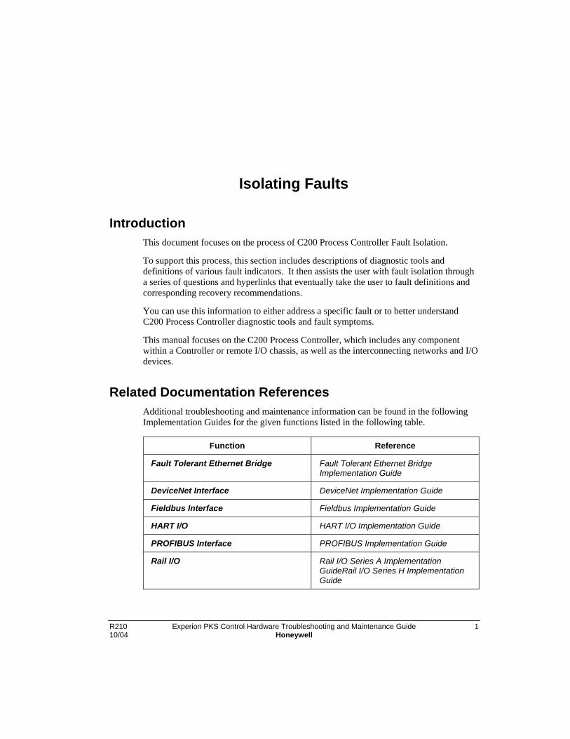
R210 Experion PKS Control Hardware Troubleshooting and Maintenance Guide 110/04 Honeywell
Isolating Faults
IntroductionThis document focuses on the process of C200 Process Controller Fault Isolation.
To support this process, this section includes descriptions of diagnostic tools anddefinitions of various fault indicators. It then assists the user with fault isolation througha series of questions and hyperlinks that eventually take the user to fault definitions andcorresponding recovery recommendations.
You can use this information to either address a specific fault or to better understandC200 Process Controller diagnostic tools and fault symptoms.
This manual focuses on the C200 Process Controller, which includes any componentwithin a Controller or remote I/O chassis, as well as the interconnecting networks and I/Odevices.
Related Documentation ReferencesAdditional troubleshooting and maintenance information can be found in the followingImplementation Guides for the given functions listed in the following table.
Function Reference
Fault Tolerant Ethernet Bridge Fault Tolerant Ethernet BridgeImplementation Guide
DeviceNet Interface DeviceNet Implementation Guide
Fieldbus Interface Fieldbus Implementation Guide
HART I/O HART I/O Implementation Guide
PROFIBUS Interface PROFIBUS Implementation Guide
Rail I/O Rail I/O Series A ImplementationGuideRail I/O Series H ImplementationGuide

Isolating FaultsTo Learn More
2 Experion PKS Control Hardware Troubleshooting and Maintenance Guide R210Honeywell 10/04
To Learn More
About … Then go to …
Why my system faulted • Fault Isolation
• Module Fault
Fault Indicators Front Panel Indicators:
• BEM
• CNI
• CPM
• Input Modules
• Output Modules
• IOLIM
• Serial Interface Modules
• RM
Fault Codes
• CNI Fault Codes
• CPM Fault Codes
• Exchange Block ERRCODE Fault Codes
• I/O Fault Codes
• PM IOP Fault Codes
• RM Fault Codes
• STI and STI_MV IOP Fault Isolation
Experion PKS Notifications
• CPM FB Generated Notifications
• NDM Detected Notifications
• NDM Generated Notifications
RM Events

Isolating FaultsTo Learn More
R210 Experion PKS Control Hardware Troubleshooting and Maintenance Guide 310/04 Honeywell
About … Then go to …
• Overview
• CNI Generated RM Events
• CPM Generated RM Events
• RM Generated Events
Test Sequence Numbers
• CPM
• RM
• SIM
Corrective Actions • General
• BEM
• CNI
• CPM
• I/O Modules
• PM I/O Processors
• Network
• Rack and Supply
• RM
Diagnostic Tools &Utilities
• CPM Tools
• Using DBADMIN
• I/O Maintenance Tool
• NetworkTools
• ENET Browser Information
RM (Workstation) Displays
• Introduction
• Redundancy Terminology

Isolating FaultsTo Learn More
4 Experion PKS Control Hardware Troubleshooting and Maintenance Guide R210Honeywell 10/04
About … Then go to …
• Accessing RM Displays
• Summary (CB) or Main (Stn) Panes
• RM Profiles (CB and Stn) Panes
• Configuration (CB and Stn) Panes
• Synchronization (CB) and Synch (Stn) Panes
• Chassis Profiles (CB and Stn) Panes
• Display (CB) Pane
• Server Parameters (CB) Pane
Reporting a problem • Effective Trouble Reporting
PM I/O EquipmentOverview
• PM I/O Subsystem Overview
• Cabinet Fan Assembly
• Field Termination Assemblies (FTAs)
• Field Termination Assemblies for IOPs
• FTA Mounting Channels
• FTA Wiring Comnection Types
• I/O Link Extender (Fiber Optic Link)
• I/O Link Interface Address Pinning
• I/O Link Interface Cabling
• IOP to FTA Cabling
• IOP/FTA 24 Vdc Fuse Protection
• IOP Card File Power Cabling
• LLAI Line Frequency Clock Voltage
• Power Adapter Cabling
• Power Distribution
• Power Systems
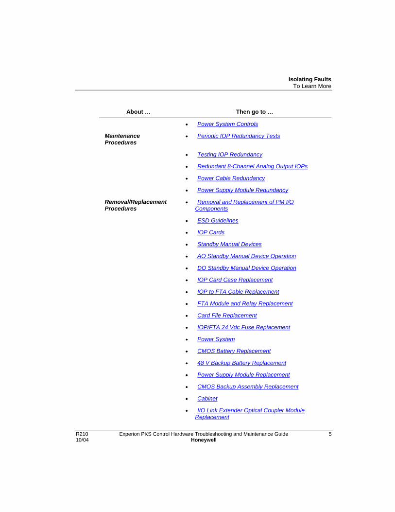
Isolating FaultsTo Learn More
R210 Experion PKS Control Hardware Troubleshooting and Maintenance Guide 510/04 Honeywell
About … Then go to …
• Power System Controls
MaintenanceProcedures
• Periodic IOP Redundancy Tests
• Testing IOP Redundancy
• Redundant 8-Channel Analog Output IOPs
• Power Cable Redundancy
• Power Supply Module Redundancy
Removal/ReplacementProcedures
• Removal and Replacement of PM I/OComponents
• ESD Guidelines
• IOP Cards
• Standby Manual Devices
• AO Standby Manual Device Operation
• DO Standby Manual Device Operation
• IOP Card Case Replacement
• IOP to FTA Cable Replacement
• FTA Module and Relay Replacement
• Card File Replacement
• IOP/FTA 24 Vdc Fuse Replacement
• Power System
• CMOS Battery Replacement
• 48 V Backup Battery Replacement
• Power Supply Module Replacement
• CMOS Backup Assembly Replacement
• Cabinet
• I/O Link Extender Optical Coupler ModuleReplacement

Isolating FaultsTo Learn More
6 Experion PKS Control Hardware Troubleshooting and Maintenance Guide R210Honeywell 10/04
About … Then go to …
Spare Parts • Spare Parts
• CNI Parts

Isolating FaultsFault Isolation
R210 Experion PKS Control Hardware Troubleshooting and Maintenance Guide 710/04 Honeywell
Fault Isolation
Start
If … Then go to …
A specific module has faulted, Module Fault
I want to know more about a diagnostictool or fault indicator,
To Learn More
Module Fault
Go to the appropriate module Fault Isolation
BEM Fault Isolation
CNI Fault Isolation
CPM Fault Isolation
RM Fault Isolation
PM IOP Fault Isolation
STI and STI_MV IOP Fault Isolation

Isolating FaultsBEM Fault Isolation
8 Experion PKS Control Hardware Troubleshooting and Maintenance Guide R210Honeywell 10/04
BEM Fault Isolation
Fault Isolation Table
If … then …
the BEM OK LED is off, Ensure chassis power is applied and/or BEM isfully inserted into the chassis.
If the BEM OK LED remains off, then go to BEMCorrective Action BEM_CA01.
the BEM OK LED is solid red, Go to BEM Corrective Action BEM_CA02.
If the BEM OK LED is solid green, No action is required.
The BEM is operating normally.
Background
The BEM is a separate, singlewide module that plugs into the Controller chassis. Itincorporates the standard ICP plastic module cover and front door. Connection to thechassis backplane is though the standard ICP connector.
The Battery Extension Module (BEM) provides battery backup power for volatilememory IC’s contained within chassis modules, such as the Control Processor Module(CPM). The battery backup is useful for maintaining memory contents, such asconfiguration databases, during temporary power outages and weekend shutdowns.
Three (3) series-connected, sub-C size, nickel-cadmium cells constitute the battery pack.Its sourcing capacity is rated at 1200mAh. In terms of what is required by the CPM, thismeans it can provide 10 milliamps of DC current at 3.6 volts for a period of 120 hours ona full charge. This figure represents the worst-case scenario for CPM operation. TheCPM typically draws 5 milliamps at reference temperature conditions and with nominalcomponents.
ATTENTION
Since aging occurs, even if the batteries have been regularly rechargedthroughout their lifetime, the NiCad battey pack Honeywell model TC-BATT03should be replaced after every two years of operation.

Isolating FaultsBEM Fault Isolation
R210 Experion PKS Control Hardware Troubleshooting and Maintenance Guide 910/04 Honeywell
There is self-test circuitry on the BEM that periodically tests for battery pack presenceand the battery-pack under load. These tests are performed only when chassis power ispresent.
A front panel LED shows the state (health) of the battery system. An integral statuscontact supports a user supplied annunciatior circuit for external/remote alarming in theevent of battery deterioration or failure. The normally-open relay contact remains closed(and the normally-closed contact remains open) when the BEM is able to provide 3.0 to3.6 Vdc battery backup power. The normally-open relay contact opens (and thenormally-closed contact closes) when the BEM is not able to provide at least 3.0 Vdcbattery backup power.
Out-Of-The-Box Assembly Required
The BEM module is shipped from the factory without the battery pack installed. Pleaserefer to the Control Hardware Installation Guide for battery pack installation details.
Out-Of-The-Box Capacity
Since Ni-Cd batteries have a high self-discharge rate, we recommend that users let theBEM module installed in a powered chassis for 24 hours prior to use. Technically, ittakes 30 to 32 hours to fully charge a set of completely discharged batteries. However,from a practical standpoint, completely discharged batteries can never be charged. Whattypically happens is that a user receives a BEM module with a battery pack charged from60% to 80% capacity available.
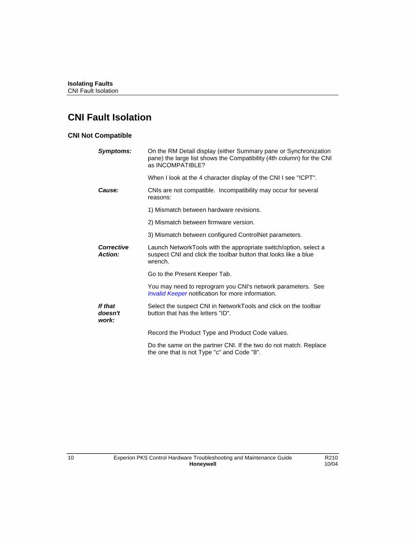
Isolating FaultsCNI Fault Isolation
10 Experion PKS Control Hardware Troubleshooting and Maintenance Guide R210Honeywell 10/04
CNI Fault Isolation
CNI Not Compatible
Symptoms: On the RM Detail display (either Summary pane or Synchronizationpane) the large list shows the Compatibility (4th column) for the CNIas INCOMPATIBLE?
When I look at the 4 character display of the CNI I see "!CPT".
Cause: CNIs are not compatible. Incompatibility may occur for severalreasons:
1) Mismatch between hardware revisions.
2) Mismatch between firmware version.
3) Mismatch between configured ControlNet parameters.
CorrectiveAction:
Launch NetworkTools with the appropriate switch/option, select asuspect CNI and click the toolbar button that looks like a bluewrench.
Go to the Present Keeper Tab.
You may need to reprogram you CNI's network parameters. SeeInvalid Keeper notification for more information.
If thatdoesn'twork:
Select the suspect CNI in NetworkTools and click on the toolbarbutton that has the letters "ID".
Record the Product Type and Product Code values.
Do the same on the partner CNI. If the two do not match. Replacethe one that is not Type "c" and Code "8".

Isolating FaultsCNI Fault Isolation
R210 Experion PKS Control Hardware Troubleshooting and Maintenance Guide 1110/04 Honeywell
Incorrect Keeper Values
Symptoms: My CNI show the words KPR ERR.
NetworkTools just popped up a dialog box indicating bad Networkvalues.
My Monitoring pane has started to show red for many items.
Cause: Bad network parameters.
CorrectiveAction:
Launch NetworkTools with the appropriate switch/option, select asuspect CNI and click the toolbar button that looks like a bluewrench.
Go to the Present Keeper Tab.
You may need to reprogram you CNI's network parameters. SeeInvalid Keeper notification for more information.
If thatdoesn'twork:
Cycle power to the CNI.
NetworkTools Related Questions
Symptoms: I have a large system and NetworkTools CNI Stats display showsmany non-concurrences.
Is there a way to diagnose ControlNet parameters?
I am planning an upgrade and know my ControlNet parametersshould change. Do I need to do this to all CNIs?
Cause: ControlNet parameters may need to change.
CorrectiveAction:
Launch NetworkTools with the appropriate switch/option, select asuspect CNI and click the toolbar button that looks like a bluewrench.
Go to the Present Keeper Tab.
You may need to reprogram you CNI's network parameters. SeeInvalid Keeper notification for more information.
If you are creating a network with parameters other than those in theprevious discussion, you must reprogram all CNIs on that network(and potential spares).
Isolating FaultsCNI Fault Isolation
12 Experion PKS Control Hardware Troubleshooting and Maintenance Guide R210Honeywell 10/04
You can diagnose the parameters by using the first toolbar button inNetworkTools. Go the to Options tab. Check the box called EnableControlNet Parameter Checking. NetworkTools will perform adiagnostic each time it is launched, if the checkbox is clicked ON orafter a change of network parameters. This check only uses thestandard Experion PKS values (it is no utility for non-standardnetwork parameteres).
If thatdoesn'twork:
Refer to the Installation manual and the Planning manual.
General CNI Questions
Symptoms: In a pinch can I use a CCR012 in a remote I/O chassis?
In a pinch can I use a CCN01x as a buddy node in a redundantmedia system?
Cause: Spares/emergencies questions.
CorrectiveAction:
At this time a CCN011 cannot be used as a buddy node in aredundant media system.
A CCR012 can be used in a remote I/O chassis.
If thatdoesn'twork:
Try the current CNI module TC-CCN013 or TC CCR013. Call TAC

Isolating FaultsCPM Fault Isolation
R210 Experion PKS Control Hardware Troubleshooting and Maintenance Guide 1310/04 Honeywell
CPM Fault Isolation
Flash ROM Programming Errors
Errors and faults encountered in the process of programming CPM Application and/orBoot firmware are not addressed in this document. In general, an error programming theApplication personality shall permit repeated attempts, while an error programming theBoot personality may require returning the module to the factory.
Fault Isolation Table
If the . . . Then See . . .
CPM is stuck displaying the sameTest Sequence Number for more than30 seconds,
Table of CPM Test Sequence Numbers
CPM is in the Fail State, CPM Fault Codes
CPM Health LED is solid red, CPM_CA05
• problem persists, CPM_CA06
CPM Battery LED is solid red, CPM_CA07
CPM is being used in a redundantconfiguration and unable tosynchronize,
CPM_CA03
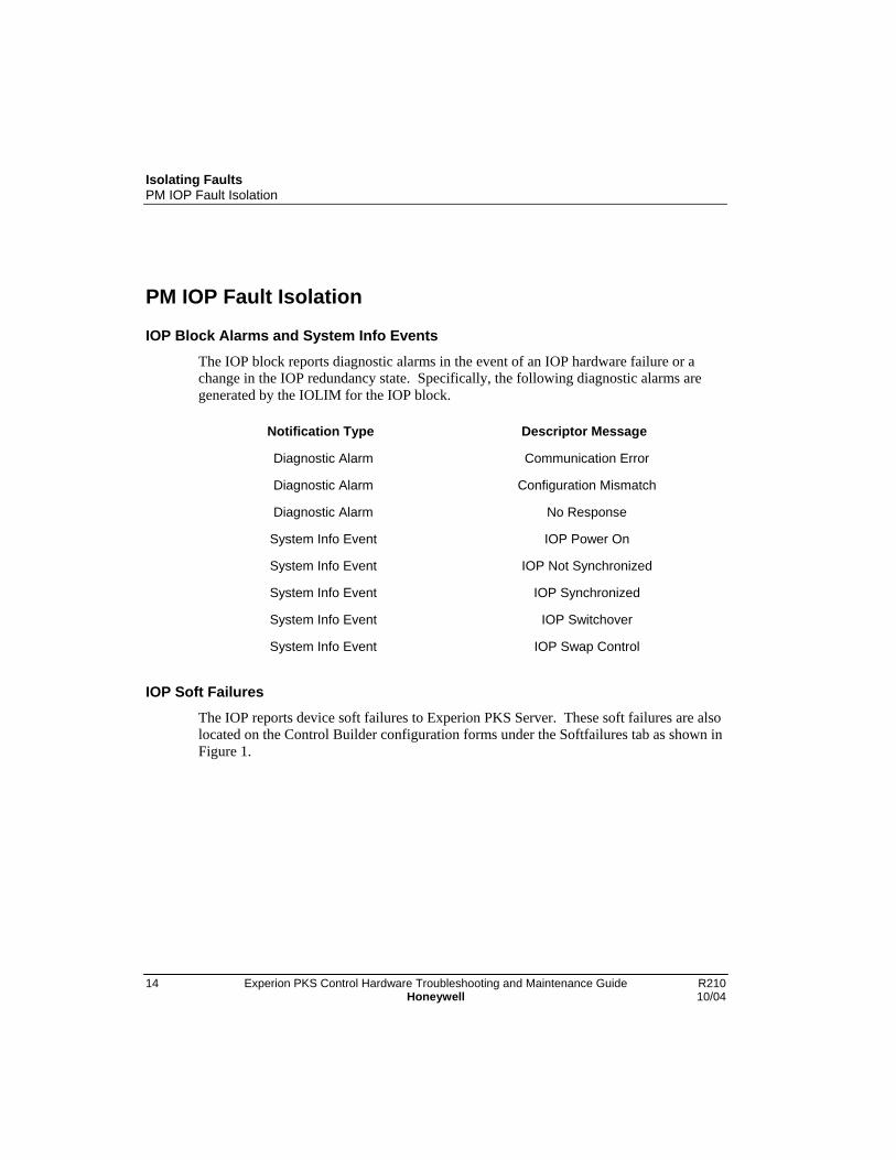
Isolating FaultsPM IOP Fault Isolation
14 Experion PKS Control Hardware Troubleshooting and Maintenance Guide R210Honeywell 10/04
PM IOP Fault Isolation
IOP Block Alarms and System Info Events
The IOP block reports diagnostic alarms in the event of an IOP hardware failure or achange in the IOP redundancy state. Specifically, the following diagnostic alarms aregenerated by the IOLIM for the IOP block.
Notification Type Descriptor Message
Diagnostic Alarm Communication Error
Diagnostic Alarm Configuration Mismatch
Diagnostic Alarm No Response
System Info Event IOP Power On
System Info Event IOP Not Synchronized
System Info Event IOP Synchronized
System Info Event IOP Switchover
System Info Event IOP Swap Control
IOP Soft Failures
The IOP reports device soft failures to Experion PKS Server. These soft failures are alsolocated on the Control Builder configuration forms under the Softfailures tab as shown inFigure 1.

Isolating FaultsPM IOP Fault Isolation
R210 Experion PKS Control Hardware Troubleshooting and Maintenance Guide 1510/04 Honeywell
Figure 1 Softfailures Flag Tab

Isolating FaultsPM IOP Fault Isolation
16 Experion PKS Control Hardware Troubleshooting and Maintenance Guide R210Honeywell 10/04
IOP Box Soft failure error codes
The IOP Box Soft failure codes are defined in the following table. Also, the correctiveactions are identified in the table.
Table 1 IOP Box Soft Failure Error Codes
ErrorCode
Description Corrective Action
00 Null Soft failure. No failure None.
01 Sample time clock overrun– greater than 2 x period.
Investigate a possible I/O Link problem. Data access tothe IOP cards may not be operating properly. Check theHigh-Performance I/O Link card, the I/O Link cable, andthe IOP cards.
02 IOP task request overflow– excessive IOL activity.
Call TAC for assistance.
03 IOP executive resumed anonwaiting task – softwarebug indicated
Call TAC for assistance.
04 Diagnostics not run in atleast 5 seconds indicates aprocessing overload.
Investigate control point mix/strategy for an excessiveload. Otherwise, a possible I/O Link problem exists.Check the High-Performance I/O Link card, the I/O Linkcable, and the IOP cards.
05 Entire diagnostic cycleoverran the 2-minuteallocated time in whichdiagnostics have to run tocompletion.
Same as error code 04.
06 The FTA is missing, or ifLLMUX, power adaptermissing.
Install the FTA. If an FTA is present, replace the FTA orcheck the FTA cable. (Note: For the LLMux or RHMUX,this code refers to the Power Adapter assembly. RTD andTC FTAs are diagnosed by error codes 50 and 51.)
07 EEPROM (used to holdcalibration information inAnalog Output IOPs)checksum failure. Itusually means an AnalogOutput IOP is notcalibrated properly.
Calibrate the Analog Output IOP card (refer to the “IOPCalibration Procedures” section for the procedure). If theerror persists, replace the HLAI, or the AO IOP card, orthe FTA.
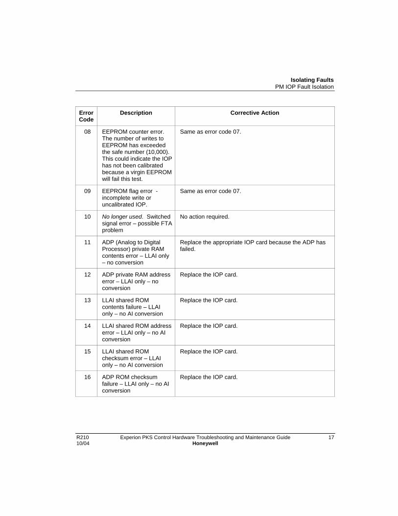
Isolating FaultsPM IOP Fault Isolation
R210 Experion PKS Control Hardware Troubleshooting and Maintenance Guide 1710/04 Honeywell
ErrorCode
Description Corrective Action
08 EEPROM counter error.The number of writes toEEPROM has exceededthe safe number (10,000).This could indicate the IOPhas not been calibratedbecause a virgin EEPROMwill fail this test.
Same as error code 07.
09 EEPROM flag error -incomplete write oruncalibrated IOP.
Same as error code 07.
10 No longer used. Switchedsignal error – possible FTAproblem
No action required.
11 ADP (Analog to DigitalProcessor) private RAMcontents error – LLAI only– no conversion
Replace the appropriate IOP card because the ADP hasfailed.
12 ADP private RAM addresserror – LLAI only – noconversion
Replace the IOP card.
13 LLAI shared ROMcontents failure – LLAIonly – no AI conversion
Replace the IOP card.
14 LLAI shared ROM addresserror – LLAI only – no AIconversion
Replace the IOP card.
15 LLAI shared ROMchecksum error – LLAIonly – no AI conversion
Replace the IOP card.
16 ADP ROM checksumfailure – LLAI only – no AIconversion
Replace the IOP card.

Isolating FaultsPM IOP Fault Isolation
18 Experion PKS Control Hardware Troubleshooting and Maintenance Guide R210Honeywell 10/04
ErrorCode
Description Corrective Action
17 ADP has failed incommunications with IOLP– recoverable-
Application processor(LLAI or STI) has acommunication failure withthe High-Performance I/OLink card.
If the error persists, replace the IOP card.
18 ADP (LLAI only) failed onIOP startup – it will notrecover
Replace the IOP card.
19 Input module scanoverrun– excessive IOLactivity to this IOP. Inputshave been lost.
Check for a "chattering" DI point. Another possible causewould be intermittently bad I/O link hardware.
20 Input module scanoverrun.
No longer used. No action required.
21 Not used. N/A
22 DOM secondary regulatoris not working.
Replace the DO IOP card.
23 Not used. N/A
24 8051stack usage isdangerously close to itslimit.
Call TAC for assistance.
25 Spare N/A
26 Input/Output loopbackfailure.
Replace the appropriate IOP card.
27 No IOLP access to sharedRAM. Input conversionwill be prohibited.
Replace the IOP card.
28 No external AC line in theLLAI – input conversionscontinue.
Check optical coupler and associated fuse on thebackpanel. Check that the primary (left side)PowerSupply Module in the Power System is installed andfunctional.

Isolating FaultsPM IOP Fault Isolation
R210 Experion PKS Control Hardware Troubleshooting and Maintenance Guide 1910/04 Honeywell
ErrorCode
Description Corrective Action
29 Not used. Not applicable.
30 Test voltage Reference>5% out of range –PVAUTO to MAN. The PVis set to NAN by the IOP.
Replace the IOP card.
31 Not used. N/A
32 Zero Reference voltageout of range. The PV is setto NAN by the IOP.
Replace the IOP card.
33 LLAI Reference junctionvalue is bad.
Check that the reference junction wire or jumper (P1) iscorrectly implemented on the FTA.
34 LLAI bad ADP branchtaken – software bug.
Replace the LLAI IOP card for the LLAI FTA.
35 Not used. N/A
36 LLMux or RHMUX: FTA #1has a Soft failure.
LLMux or RHMUX: Check FTA 1.SI: Correct the error condition at the device connected toFTA 1.
37 LLMux or RHMUX: FTA #2has a Soft failure.
LLMux or RHMUX: Check FTA 2.SI: Correct the error condition at the device connected toFTA 2.
38 Calibration of a modulehas been aborted due to afailure.
Check the precision voltage/resistance source foraccuracy. Also, make sure that the correct calibrationprocedure is being followed
39 Calibration voltage out ofrange.
Replace the HLAI.
40 EEPROM store failed –calibration data may belost..
If an HLAI or AO, replace the IOP. If an LLAI, replace theaffected plug-in module.
41 LLMUX FTA referencevoltage out of range
If the problem persists replace the FTA
42 Not used. N/A
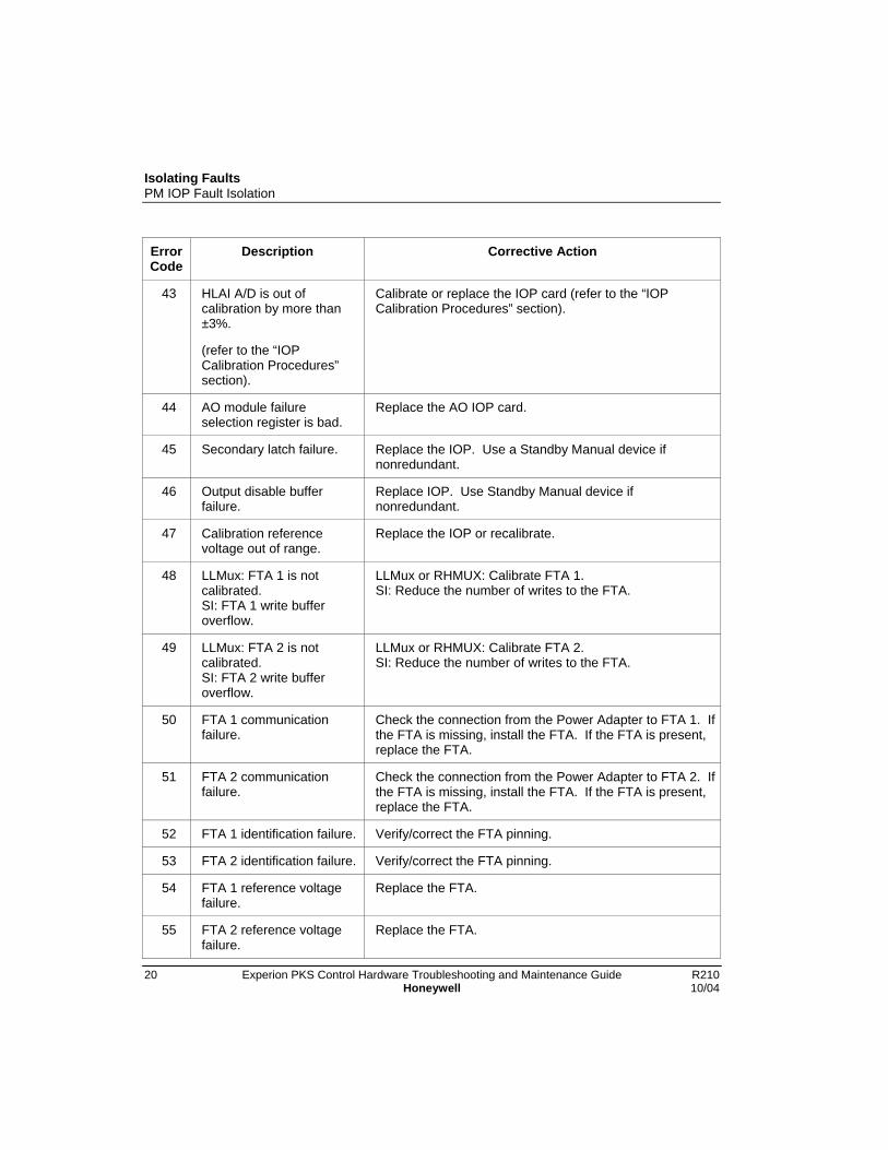
Isolating FaultsPM IOP Fault Isolation
20 Experion PKS Control Hardware Troubleshooting and Maintenance Guide R210Honeywell 10/04
ErrorCode
Description Corrective Action
43 HLAI A/D is out ofcalibration by more than±3%.
(refer to the “IOPCalibration Procedures”section).
Calibrate or replace the IOP card (refer to the “IOPCalibration Procedures” section).
44 AO module failureselection register is bad.
Replace the AO IOP card.
45 Secondary latch failure. Replace the IOP. Use a Standby Manual device ifnonredundant.
46 Output disable bufferfailure.
Replace IOP. Use Standby Manual device ifnonredundant.
47 Calibration referencevoltage out of range.
Replace the IOP or recalibrate.
48 LLMux: FTA 1 is notcalibrated.SI: FTA 1 write bufferoverflow.
LLMux or RHMUX: Calibrate FTA 1.SI: Reduce the number of writes to the FTA.
49 LLMux: FTA 2 is notcalibrated.SI: FTA 2 write bufferoverflow.
LLMux or RHMUX: Calibrate FTA 2.SI: Reduce the number of writes to the FTA.
50 FTA 1 communicationfailure.
Check the connection from the Power Adapter to FTA 1. Ifthe FTA is missing, install the FTA. If the FTA is present,replace the FTA.
51 FTA 2 communicationfailure.
Check the connection from the Power Adapter to FTA 2. Ifthe FTA is missing, install the FTA. If the FTA is present,replace the FTA.
52 FTA 1 identification failure. Verify/correct the FTA pinning.
53 FTA 2 identification failure. Verify/correct the FTA pinning.
54 FTA 1 reference voltagefailure.
Replace the FTA.
55 FTA 2 reference voltagefailure.
Replace the FTA.
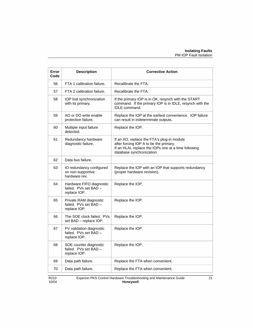
Isolating FaultsPM IOP Fault Isolation
R210 Experion PKS Control Hardware Troubleshooting and Maintenance Guide 2110/04 Honeywell
ErrorCode
Description Corrective Action
56 FTA 1 calibration failure. Recalibrate the FTA.
57 FTA 2 calibration failure. Recalibrate the FTA.
58 IOP lost synchronizationwith its primary.
If the primary IOP is in OK, resynch with the STARTcommand. If the primary IOP is in IDLE, resynch with theIDLE command.
59 AO or DO write enableprotection failure.
Replace the IOP at the earliest convenience. IOP failurecan result in indeterminate outputs.
60 Multiple input failuredetected.
Replace the IOP.
61 Redundancy hardwarediagnostic failure.
If an AO, replace the FTA’s plug-in moduleafter forcing IOP A to be the primary.If an HLAI, replace the IOPs one at a time followingdatabase synchronization.
62 Data bus failure.
63 IO redundancy configuredon non-supportivehardware rev.
Replace the IOP with an IOP that supports redundancy(proper hardware revision).
64 Hardware FIFO diagnosticfailed. PVs set BAD –replace IOP.
Replace the IOP.
65 Private RAM diagnosticfailed. PVs set BAD –replace IOP.
Replace the IOP.
66 The SOE clock failed. PVsset BAD – replace IOP.
Replace the IOP.
67 PV validation diagnosticfailed. PVs set BAD –replace IOP.
Replace the IOP.
68 SOE counter diagnosticfailed. PVs set BAD –replace IOP.
Replace the IOP.
69 Data path failure. Replace the FTA when convenient.
70 Data path failure. Replace the FTA when convenient.

Isolating FaultsPM IOP Fault Isolation
22 Experion PKS Control Hardware Troubleshooting and Maintenance Guide R210Honeywell 10/04
ErrorCode
Description Corrective Action
71 State machine diagnosticfailed. PVs set BAD –replace IOP.
Recalibrate the FTA.
72 Bad personality image. - Reload personality image?
73 Bad BS and/or PS imagein Flash ROM.
-
74 Bad CRC for PS FlashROM image.
-
75 Bad AS image in FlashROM.
-
76to
114
Not used. N/A
115 Spare
116to
160
Not used. N/A
161 HART hardware errordetected against DUARTchannel 1 or modem 1.
Replace the IOP card.
162 HART hardware errordetected against DUARTchannel 2 or modem 2.
Replace the IOP card.
163 HART hardware errordetected against DUARTchannel 3 or modem 3.
Replace the IOP card.
164 HART hardware errordetected against DUARTchannel 4 or modem 4.
Replace the IOP card.
165 HART processor programstack above 90% usagelevel.
166 HART processordiagnostic task under-run

Isolating FaultsPM IOP Fault Isolation
R210 Experion PKS Control Hardware Troubleshooting and Maintenance Guide 2310/04 Honeywell
IOP Channel Soft failure error codes
These diagnostic alarms for the IOP Channel Block are reported in the event of an IOPhardware failure. These notifications are also located on the Control Builder IOP Blockconfiguration forms under the Channel Soft Failures tab. The recommended correctiveactions are included in the table.
Table 2 IOP Channel Soft Failure Error Codes
ErrorCode
Description Corrective Action
00 No error
01to06
Not used. N/A
07 LLAI EEPROM checksum error orIOP not calibrated.
Replace the FTA plug-in module or recalibrate.
08 LLAI EEPROM counter error – toomany writes or unformattedEEPROM.
Replace the FTA plug-in module or recalibrate.
09to20
Not used. N/A
21 Input point failed diagnostic. Replace the IOP or check the FTA wiring.
22 Not used. N/A
23 Failure in output circuitry detectedby AO or DO
Check the output connection at the FTA. If it isgood, try replacing the FTA and/or theappropriate IOP card.
24to28
Not used. N/A
29 Bad input or bad FTA plug-inmodule
Test that the slot is wired correctly. If it is,replace the FTA plug-in module.
30 Not used. N/A
31 FTA type mismatch with slotconfiguration.
Reconfigure or replace the FTA.
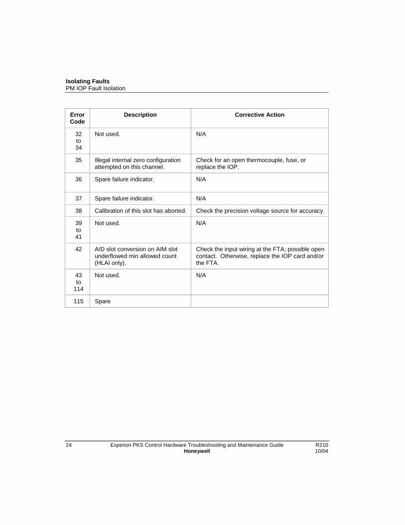
Isolating FaultsPM IOP Fault Isolation
24 Experion PKS Control Hardware Troubleshooting and Maintenance Guide R210Honeywell 10/04
ErrorCode
Description Corrective Action
32to34
Not used. N/A
35 Illegal internal zero configurationattempted on this channel.
Check for an open thermocouple, fuse, orreplace the IOP.
36 Spare failure indicator. N/A
37 Spare failure indicator. N/A
38 Calibration of this slot has aborted. Check the precision voltage source for accuracy.
39to41
Not used. N/A
42 A/D slot conversion on AIM slotunderflowed min allowed count(HLAI only).
Check the input wiring at the FTA; possible opencontact. Otherwise, replace the IOP card and/orthe FTA.
43to
114
Not used. N/A
115 Spare

Isolating FaultsRM Fault Isolation
R210 Experion PKS Control Hardware Troubleshooting and Maintenance Guide 2510/04 Honeywell
RM Fault Isolation
If … then …
“THxy” on stalled RM front paneldisplay.
(“xy” represents any 2 alphanumericcharacters)
The RM has failed a startup test.
Go to RM Test Sequence Numbers
“Exyz” error code on RM front paneldisplay.
(“xyz” represents any 3 alphanumericcharacters)
The RM has encountered a run-time error.
Go to the corresponding code at RM FaultCodes
“OK” LED solid red on RM frontpanel.
(with no “Exyz” error code displayed).
The RM has encountered a severe run-timeerror.
First, take RM Corrective Action RM_CA02.
If the problem persists, take RM CorrectiveAction RM_CA01.
And if it still persists, take General CorrectiveAction GEN_CA01
STI and STI_MV IOP Fault IsolationThis section discusses transmitter error and diagnostic messages associated with SmartTransmitter Interface (STI) or Smart Transmitter Interface Multivariable (STI_MV) IOPoperation which may be sent to the Operator Station or SFC. Error codes for varioussmart transmitters are listed along with suggested corrective actions.

Isolating FaultsSTI and STI_MV IOP Fault Isolation
26 Experion PKS Control Hardware Troubleshooting and Maintenance Guide R210Honeywell 10/04
Process Variable Reliability
The replacement of an analog PV signal with a digital PV signal can represent anincrease in process value security if all the proper measures discussed below areimplemented. The DE protocol provides the means necessary for accurate securedcommunication of process signals between field devices and their controllers. Whenused in conjunction with a Smart Transmitter IOP board, increased knowledge of thefield device is provided along with the signal processing required for the digital PV toattain its high level of performance.
The analog version of the PV contains no checks and balances of any form to indicate tothe control system the instantaneous validity of the PV signal. Also, the analog PVsignal is not impervious to noise and the control system has no means of recovering lostor corrupted analog PV signals.
It should be noted that the control system, in a DE protocol environment, functions as apassive listener only and is incapable of polling field sensors. As a result, lost orcorrupted digital PV data cannot be retransmitted by request. In fact, if that werepossible, more PVs would be lost due to the increased communication activity.
Since the DE protocol requires that the field device continuously broadcast PVs, loss ofone sample is immediately followed by another sample. As a result, the control system(Smart Transmitter IOP) need only determine whether a given sample is good or bad.This analysis serves to establish the rate at which the controller can be expected to missPVs due to a corrupted digital communication channel, and also to establish a rate atwhich the Smart Transmitter IOP can be expected to detect that corruption.
The analysis falls into three categories:
• Error detection
• Noise immunity
• Noise rejection
Isolating FaultsSTI and STI_MV IOP Fault Isolation
R210 Experion PKS Control Hardware Troubleshooting and Maintenance Guide 2710/04 Honeywell
Error Detection
The Digital Enhanced (DE) protocol incorporates two means of enhancing errordetection:
• Field Device Status
• Information Redundancy
Field Device Status
The original analog version of the PV has no way of indicating field device failures to thecontrol system, instantly. Many field devices use a burnout technique to indicate devicefailures—this is usually not instantaneous, and the controller may have already beguncontrol on a signal being driven towards burnout. Consequently, there is no effectivemeans to indicate to the control system the validity of an analog PV signal.
The DE protocol, however, requires that an indication of the field device status betransmitted with every digital PV value. As a result, a controller is never controlling aPV from a known bad field device.
Information Redundancy
Redundancy is the addition of noninformation carrying bits so that particularmathematical calculations can be made at the receive end to determine whether the groupof bits, including the redundant bits, are the same as those transmitted. This processensures that the original information was correctly received while allowing the capabilityto detect bad message blocks and have them rejected by the system. The DE protocolcontains Byte parity (VRC) redundant bits in the message block.
The digital PV value is contained in bytes 2 through 4 of the message block. As a furthermeans of screening potentially bad PV data, all consecutive byte parities (for bytes 1through 4) must be good before a new digital PV value is accepted by the SmartTransmitter IOP.
Isolating FaultsSTI and STI_MV IOP Fault Isolation
28 Experion PKS Control Hardware Troubleshooting and Maintenance Guide R210Honeywell 10/04
Standardized tests
The following tests were performed on the actual hardware with the results focused onthe PV validity. Test reports are available from Honeywell by special request.
• Temperature
• Voltage Margin
• Power Cycling
• ANSI Surge
• RFI
• ESD
• Fault Insertion
Noise Immunity
In DE protocol, increased noise immunity is gained by using a digital communicationbaud rate that is low in frequency relative to its environmental noise. The DE protocoltransmits at a rate of 218 baud. The advantages of this are
1. High frequency noise can be easily filtered out with simple RC filters (on the SmartTransmitter IOP board).
2. It is less likely that burst noise will last long enough or contain enough energy tointerfere with the signal.
Noise immunity is also gained by selecting significantly large and differentvoltage/current levels to represent a logical 1 and 0. For the DE protocol, these levels are4 mA/1 volt and 20 mA/5 volts.
Isolating FaultsSTI and STI_MV IOP Fault Isolation
R210 Experion PKS Control Hardware Troubleshooting and Maintenance Guide 2910/04 Honeywell
Noise Rejection
The term noise rejection indicates that the digital PV signal is communicating throughtwisted pair wire in floating point numbers.
Since noise rejection assumes that noise has already corrupted the signal, all noiserejection techniques, in DE protocol, are only applicable to the Smart Transmitter IOP.The Smart Transmitter IOP has the capability of rejecting noise using four techniques:
1. Digital Input Filtering—the IOP contains a simple RC input filter to eliminate highfrequency noise. The –3db point is set at 482 Hz.
2. Samples per Bit—The IOP software UART will take five samples per bit and use avoting technique before declaring a given logic level. Four of the five bit samplesmust agree for data to be considered good.
3. Floating Point Value Check—The IOP software verifies that the received floatingpoint value is of a valid form. All floating point values that do not conform arerejected.
4. Digital Noise Filtering—The IOP software treats the received good digital PV as areal signal by not allowing unusually large instantaneous transitions to occur. This isaccomplished by comparing the received digital PV sample with the previous sample.If the new sample differs by greater than 30% of the working range, the new value isdiscarded and the old value is used for control. The next digital PV value is alwaysused. This technique allows the IOP to reject multibit errors which might passundetected and corrupt the digital PV. Its limitations are that it can only reject onenoise sample and it causes a temporary lag in the process.
Smart Transmitter Error Codes
The following tables list error codes that appear on the STI_MV point detail display atthe station as IOP diagnostics for ST3000, STT3000, and MagneW3000 SmartlineTransmitters.
Error codes for multivariable field devices (SMV 3000) are described in the user manualfor that specific field device.
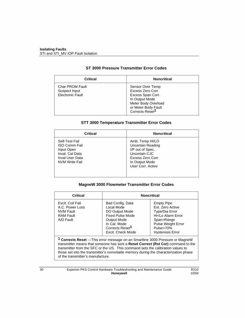
Isolating FaultsSTI and STI_MV IOP Fault Isolation
30 Experion PKS Control Hardware Troubleshooting and Maintenance Guide R210Honeywell 10/04
ST 3000 Pressure Transmitter Error Codes
Critical Noncritical
Char PROM FaultSuspect InputElectronic Fault
Sensor Over TempExcess Zero Corr.Excess Span Corr.In Output ModeMeter Body Overloador Meter Body FaultCorrects Reset1
STT 3000 Temperature Transmitter Error Codes
Critical Noncritical
Self-Test FailISO Comm FailInput OpenInval. Cal DataInval User DataNVM Write Fail
Amb. Temp HI/LOUncertain ReadingI/P out of Spec.Uncertain CJCExcess Zero Corr.In Output ModeUser Corr. Active
MagneW 3000 Flowmeter Transmitter Error Codes
Critical Noncritical
Excit. Coil Fail.A.C. Power LossNVM FaultRAM FaultA/D Fault
Bad Config. DataLocal ModeDO Output ModeFixed Pulse ModeOutput ModeIn Cal. ModeCorrects Reset1Excit. Check Mode
Empty PipeExt. Zero ActiveType/Dia ErrorHi<Lo Alarm ErrorSpan>RangePulse Weight ErrorPulse>70%Hysteresis Error
1 Corrects Reset —This error message on an Smartline 3000 Pressure or MagneWtransmitter means that someone has sent a Reset Correct (Rst Cor) command to thetransmitter from the SFC or the US. This command sets the calibration values tothose set into the transmitter’s nonvolatile memory during the characterization phaseof the transmitter’s manufacture.
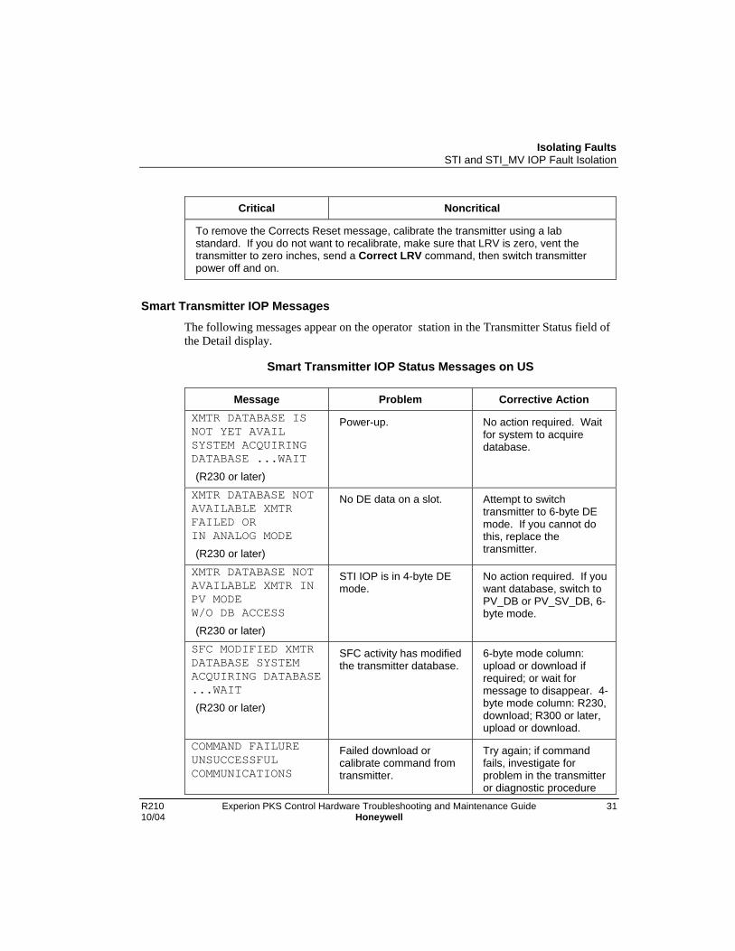
Isolating FaultsSTI and STI_MV IOP Fault Isolation
R210 Experion PKS Control Hardware Troubleshooting and Maintenance Guide 3110/04 Honeywell
Critical Noncritical
To remove the Corrects Reset message, calibrate the transmitter using a labstandard. If you do not want to recalibrate, make sure that LRV is zero, vent thetransmitter to zero inches, send a Correct LRV command, then switch transmitterpower off and on.
Smart Transmitter IOP Messages
The following messages appear on the operator station in the Transmitter Status field ofthe Detail display.
Smart Transmitter IOP Status Messages on US
Message Problem Corrective ActionXMTR DATABASE ISNOT YET AVAILSYSTEM ACQUIRINGDATABASE ...WAIT
(R230 or later)
Power-up. No action required. Waitfor system to acquiredatabase.
XMTR DATABASE NOTAVAILABLE XMTRFAILED ORIN ANALOG MODE
(R230 or later)
No DE data on a slot. Attempt to switchtransmitter to 6-byte DEmode. If you cannot dothis, replace thetransmitter.
XMTR DATABASE NOTAVAILABLE XMTR INPV MODEW/O DB ACCESS
(R230 or later)
STI IOP is in 4-byte DEmode.
No action required. If youwant database, switch toPV_DB or PV_SV_DB, 6-byte mode.
SFC MODIFIED XMTRDATABASE SYSTEMACQUIRING DATABASE...WAIT
(R230 or later)
SFC activity has modifiedthe transmitter database.
6-byte mode column:upload or download ifrequired; or wait formessage to disappear. 4-byte mode column: R230,download; R300 or later,upload or download.
COMMAND FAILUREUNSUCCESSFULCOMMUNICATIONS
Failed download orcalibrate command fromtransmitter.
Try again; if commandfails, investigate forproblem in the transmitteror diagnostic procedure

Isolating FaultsSTI and STI_MV IOP Fault Isolation
32 Experion PKS Control Hardware Troubleshooting and Maintenance Guide R210Honeywell 10/04
Message Problem Corrective Action
(R300 or later) on the communicationlink.
COMMAND FAILUREINVALID REQUEST
(R300 or later)
Failed download orcalibrate command fromtransmitter.
Verify that the correctfunction has beenrequested.
COMMAND FAILURELOCAL MODE
(R300 or later, MagneWonly)
Failed download orcalibrate command fromtransmitter.
Refer to MagneW 3000Magnetic FlowmeterUser’s Guide, 36-KI-25-01.
COMMAND FAILUREFIELD DEVICE ISWRITE PROTECTED
(R300 or later, MagneWor ST only)
Failed download orcalibrate command fromtransmitter.
Remove the write protectfrom the transmitter.Refer to MagneW 3000Magnetic FlowmeterUser’s Guide, 36-KI-25-01or ST 3000 SmartTransmitter User’sManual, 34-ST-32-02B.
COMMAND FAILURENVM BAD
(R300 or later)
Failed download orcalibrate command fromtransmitter.
Replace transmitter.
COMMAND ALLOWEDONLY ON FIRST SLOTOF MULTIPLE PVXMTRS
Attempted to downloaddatabase with DECONFchange from slot 2, 3, or4.
Call up slot 1 Detaildisplay for PV1 and retrydatabase downloadcommand.
COMMAND FAILURE. . . BUSY
Command could not beexecuted becausetransmitter is busy
Retry command.
CONFIGURATIONMISMATCH MULTIPLEDEVICES ASSIGNEDTO SLOT
Another transmitter isphysically connected to alogical slot for amultivariable transmitter.
Disconnect offendingtransmitter or reconfigurethe number of PVs for theSMV 3000 transmitter.
TRANSMITTER ISBROADCASTING ASUBSTITUTE VALUEPV
Transmitter is in outputmode or input mode.
Use SCT 3000 to removetransmitter from outputmode or input mode.
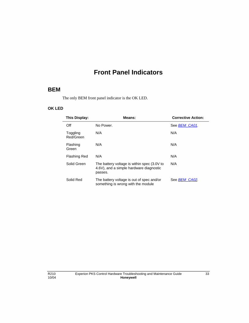
R210 Experion PKS Control Hardware Troubleshooting and Maintenance Guide 3310/04 Honeywell
Front Panel Indicators
BEMThe only BEM front panel indicator is the OK LED.
OK LED
This Display: Means: Corrective Action:
Off No Power. See BEM_CA01.
TogglingRed/Green
N/A N/A
FlashingGreen
N/A N/A
Flashing Red N/A N/A
Solid Green The battery voltage is within spec (3.0V to4.6V), and a simple hardware diagnosticpasses.
N/A
Solid Red The battery voltage is out of spec and/orsomething is wrong with the module
See BEM_CA02.

Front Panel IndicatorsCNI
34 Experion PKS Control Hardware Troubleshooting and Maintenance Guide R210Honeywell 10/04
CNI
Normal Runtime Displays
A ControlNet interface module in either a standalone or redundant configurationnormally displays the following messages. Note that the messages are listed in thesequence in which they are displayed.
4 Character DisplayMessage
Description of Cause
(A,#,x,x) Address indication where xx indicates the ControlNet Mac ID.
( ,O,K, ,) CNI is operating normally
“RedundancyState”
Refer to Controller Redundancy Specific Displays if CNI resides in aredundant chassis.
(%,C,x,x) Percentage of CPU usage where xx is in the range 00 - 99%.Because of display limitations, the maximum value displayed will be99% even if CPU usage reaches 100%.
(K,p,x,x) Module's keeper state, where xx can be one of the followingabbreviations:
Ov - the keeper is powering up or off line with valid keeper informationthat may or may not match the network keeper signature.
Oi - the keeper is powering up or off line with invalid keeperinformation.
Av - the keeper is the active network keeper, with valid keeperinformation, whose keeper signature defines the network keepersignature.
Iv - the keeper is an inactive network keeper with valid keeperinformation that matches the network keeper signature.
Ai - the keeper is the active network keeper either with invalid keeperinformation or with a keeper signature that does not match thenetwork keeper signature.
Ii - the keeper is an inactive network keeper either with invalid keeperinformation or with a keeper signature that does not match thenetwork keeper signature.
(n,C,x,x) Number of open connections used by the CNI, where xx is in the rageof 00 to 64 connections.

Front Panel IndicatorsCNI
R210 Experion PKS Control Hardware Troubleshooting and Maintenance Guide 3510/04 Honeywell
4 Character DisplayMessage
Description of Cause
(n,U,x,x) Number of unconnected buffers used by the CNI, where xx is in therange of 00 to 20 buffers.
(B,x,n,n) Number of bandwidth exceeded occurrences since the last powercycle or module reset, where nn is in the range of 00 to 99occurrences after which the display rolls over to 00 and continuescounting.
A bandwidth exceeded error occurs whenever module has all itsreceive buffers in use at the same time and an additional buffer isneeded. At that point, the module clears all of the received buffersthus destroying their contents, in an effort to recover from theresource overload.
A bandwidth exceeded error might also occur when the modulefirmware is flash updated. In this case, clearing of the buffers isnecessary to begin the flash update process. This error isautomatically cleared after the flash process by way of the modulereset after the flash update.
The bandwidth exceeded count display is disabled until the firstbandwidth exceeded event is detected. Once one has occurred, thedisplay will remain activated and be a part of the display sequence.The count and display is cleared whenever the module is reset orpower cycled.

Front Panel IndicatorsCNI
36 Experion PKS Control Hardware Troubleshooting and Maintenance Guide R210Honeywell 10/04
Abnormal Displays
A ControlNet interface module in either a standalone or redundant configuration candisplay the following messages.
OKStatusLight
4 Character DisplayMessage
Description of Cause Corrective Action
GREEN (I,N,I,T,) CNI is performing post powerupinitialization.
Wait
GREEN ( ,O,K, ,) CNI is operating normally None needed
FL.RED (R,O,M, ,U,P,D,T) flash loading from application isin progress
Wait
GREEN ( ,S,W, ,E,R,R, ) Mac ID Switch changed afterpowerup or when in a redundantsecondary, Mac ID not set thesame as primary.
Adjust switchsettings
FL.GRN (C,N,F,G,E,R,R, ) ControlNet Config error Call SSC
RED (A,D,D,R,E,R,R, ) Two node 1's, or node set to 00or node 99 if redundant
Adjust switchsettings
RED (R,A,C,K,E,R,R, ) Cannot read backplane EPROMor rack/slot address incorrect
Call SSC
RED (D,U,P,L,N,O,D,E) There is another node on thenetwork at the same address(May be a temporary conditionduring redundant switchover)
Adjust switchsettings (unlesstemporarycondition duringswitchover)
FL.GRN (N,E,T, ,E,R,R, ) CNI cannot find networkconnection
Check that all dropcables areattached, checkfor faulty drop,check cabling ingeneral
RED (C,N,I,C,E,R,R, ) Cnet ASIC Error Call SSC
RED (B,P,I,C,E,R,R, ) Backplane ASIC error Call SSC
RED (B,P,R,X,E,R,R, ) Backplane receiver error Call SSC

Front Panel IndicatorsCNI
R210 Experion PKS Control Hardware Troubleshooting and Maintenance Guide 3710/04 Honeywell
OKStatusLight
4 Character DisplayMessage
Description of Cause Corrective Action
RED (B,P,A,#,E,R,R, ) Backplane address # (slotnumber) error
Call SSC
GREEN ( ,B,W, ,>,M,A,X) Bandwidth exceeded, temporaryCnet scheduling problem
wait
RED (S,T,O,P,) CNI commanded to stopfunctioning by the RedundancyModule (Occurs when a nonredundancy compliant CNI isplaced into a redundantsecondary chassis)
Check that thestopped CNI isredundancycapable (TC-CCx012 or TC-CCx013 where xequals N or R)

Front Panel IndicatorsCNI
38 Experion PKS Control Hardware Troubleshooting and Maintenance Guide R210Honeywell 10/04
Controller Redundancy Specific Displays
A redundant compliant ControlNet interface module in only a redundant configurationcan display the following messages.
OKStatusLight
4 Character DisplayMessage
Description of Cause Corrective Action
RED (W,A,I,T, ,R,M, ) CNI waiting for the RedundancyModule to complete powerup
wait
GREEN (P,w,D,S) CNI is primary with adisqualified secondary partner
SynchronizeSecondary
GREEN (P,w,Q,g) CNI is primary with a qualifyingsecondary partner
wait
GREEN (P,w,Q,S) CNI is primary with a qualifiedsecondary partner
None needed
GREEN (P,w,N,S) CNI is primary with a nosecondary partner
Inspect secondary
GREEN (Q,U,A,L) Primary CNI is qualified with itspartner
wait
GREEN (C,M,P,T) Secondary CNI is compatiblewith its partner
wait
GREEN (D,I,S,Q) Secondary CNI is disqualified SynchronizeSecondary
GREEN (Q,f,n,g) Secondary CNI is qualifying wait
GREEN ( ,Q,S, ) Secondary CNI is qualified None needed
GREEN (D,S,N,P) Secondary CNI is disqualifiedwith no partner
Inspect partnerand RMs
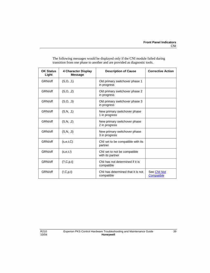
Front Panel IndicatorsCNI
R210 Experion PKS Control Hardware Troubleshooting and Maintenance Guide 3910/04 Honeywell
The following messages would be displayed only if the CNI module failed duringtransition from one phase to another and are provided as diagnostic tools.
OK StatusLight
4 Character DisplayMessage
Description of Cause Corrective Action
GRN/off (S,O, ,1) Old primary switchover phase 1in progress
GRN/off (S,O, ,2) Old primary switchover phase 2in progress
GRN/off (S,O, ,3) Old primary switchover phase 3in progress
GRN/off (S,N, ,1) New primary switchover phase1 in progress
GRN/off (S,N, ,2) New primary switchover phase2 in progress
GRN/off (S,N, ,3) New primary switchover phase3 in progress
GRN/off (s,e,t,C) CNI set to be compatible with itspartner
GRN/off (s,e,t,!) CNI set to not be compatiblewith its partner
GRN/off (?,C,p,t) CNI has not determined if it iscompatible
GRN/off (!,C,p,t) CNI has determined that it is notcompatible
See CNI NotCompatible

Front Panel IndicatorsCNI
40 Experion PKS Control Hardware Troubleshooting and Maintenance Guide R210Honeywell 10/04
Common questions
Question Answer
1. My CNI shows the word !CPT.Is this an error?
A display of !CPT is not normal and needs correctiveaction. See CNI Not Compatible.
2. My CNI shows the word FAULT orASSERT scrolling across it.Is this an error?
If the CNI is displaying FAULT or ASSERT or thehealth LED is solid Red, copy down the exactsequence of symbols being shwon on the 4 characterdisplay. See Getting CPM Breadcrumbs and GettingRM Events from the Primary and Seconday, if this isa Redundant C200 Controller. Cycle power to thechassis.
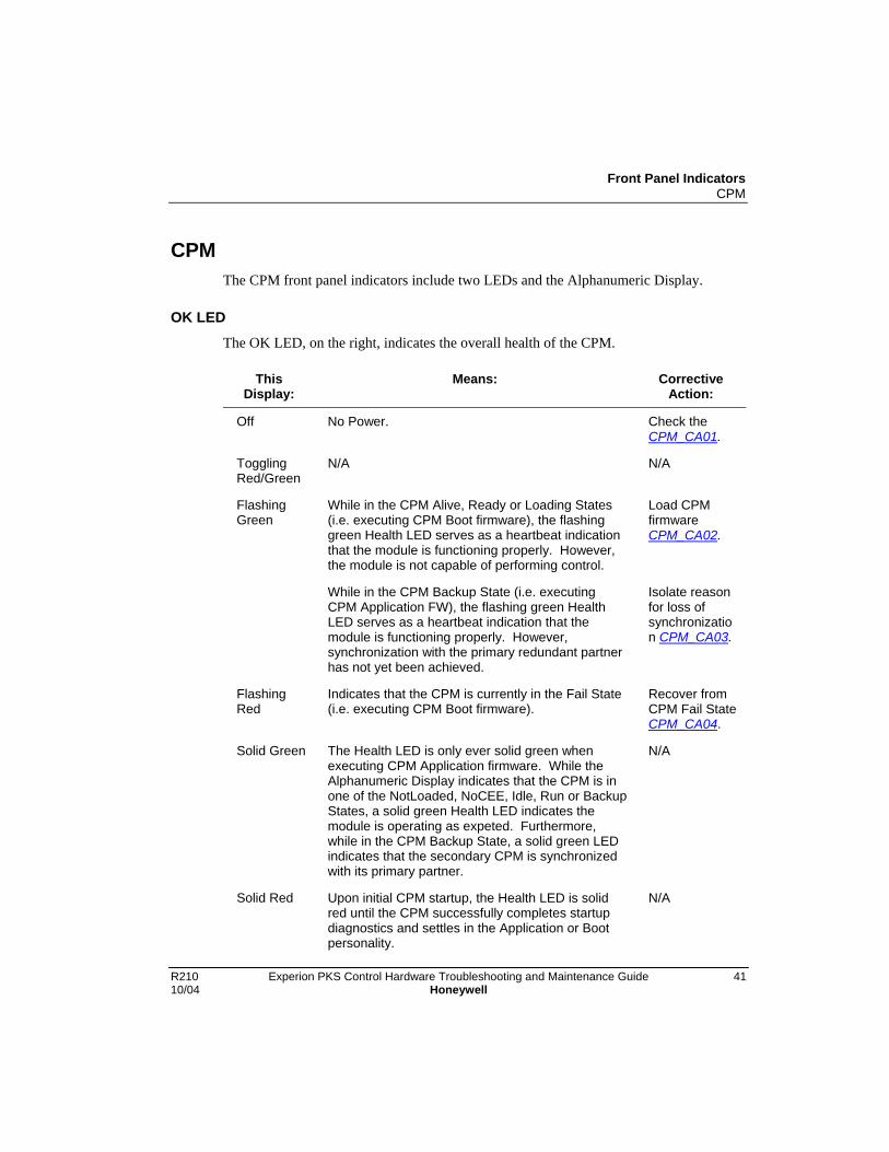
Front Panel IndicatorsCPM
R210 Experion PKS Control Hardware Troubleshooting and Maintenance Guide 4110/04 Honeywell
CPMThe CPM front panel indicators include two LEDs and the Alphanumeric Display.
OK LEDThe OK LED, on the right, indicates the overall health of the CPM.
ThisDisplay:
Means: CorrectiveAction:
Off No Power. Check theCPM_CA01.
TogglingRed/Green
N/A N/A
FlashingGreen
While in the CPM Alive, Ready or Loading States(i.e. executing CPM Boot firmware), the flashinggreen Health LED serves as a heartbeat indicationthat the module is functioning properly. However,the module is not capable of performing control.
Load CPMfirmwareCPM_CA02.
While in the CPM Backup State (i.e. executingCPM Application FW), the flashing green HealthLED serves as a heartbeat indication that themodule is functioning properly. However,synchronization with the primary redundant partnerhas not yet been achieved.
Isolate reasonfor loss ofsynchronization CPM_CA03.
FlashingRed
Indicates that the CPM is currently in the Fail State(i.e. executing CPM Boot firmware).
Recover fromCPM Fail StateCPM_CA04.
Solid Green The Health LED is only ever solid green whenexecuting CPM Application firmware. While theAlphanumeric Display indicates that the CPM is inone of the NotLoaded, NoCEE, Idle, Run or BackupStates, a solid green Health LED indicates themodule is operating as expeted. Furthermore,while in the CPM Backup State, a solid green LEDindicates that the secondary CPM is synchronizedwith its primary partner.
N/A
Solid Red Upon initial CPM startup, the Health LED is solidred until the CPM successfully completes startupdiagnostics and settles in the Application or Bootpersonality.
N/A
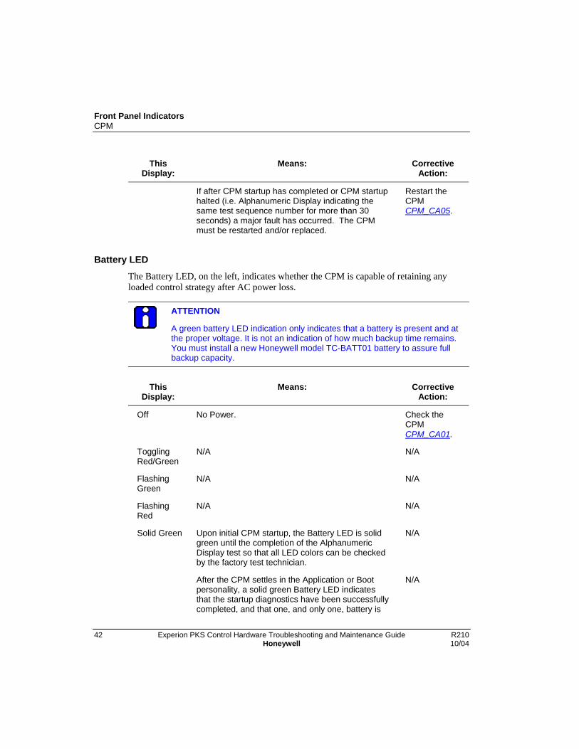
Front Panel IndicatorsCPM
42 Experion PKS Control Hardware Troubleshooting and Maintenance Guide R210Honeywell 10/04
ThisDisplay:
Means: CorrectiveAction:
If after CPM startup has completed or CPM startuphalted (i.e. Alphanumeric Display indicating thesame test sequence number for more than 30seconds) a major fault has occurred. The CPMmust be restarted and/or replaced.
Restart theCPMCPM_CA05.
Battery LED
The Battery LED, on the left, indicates whether the CPM is capable of retaining anyloaded control strategy after AC power loss.
ATTENTION
A green battery LED indication only indicates that a battery is present and atthe proper voltage. It is not an indication of how much backup time remains.You must install a new Honeywell model TC-BATT01 battery to assure fullbackup capacity.
ThisDisplay:
Means: CorrectiveAction:
Off No Power. Check theCPMCPM_CA01.
TogglingRed/Green
N/A N/A
FlashingGreen
N/A N/A
FlashingRed
N/A N/A
Solid Green Upon initial CPM startup, the Battery LED is solidgreen until the completion of the AlphanumericDisplay test so that all LED colors can be checkedby the factory test technician.
N/A
After the CPM settles in the Application or Bootpersonality, a solid green Battery LED indicatesthat the startup diagnostics have been successfullycompleted, and that one, and only one, battery is
N/A

Front Panel IndicatorsCPM
R210 Experion PKS Control Hardware Troubleshooting and Maintenance Guide 4310/04 Honeywell
ThisDisplay:
Means: CorrectiveAction:
present and of proper voltage.
Solid Red During CPM startup, the Battery LED is solid reduntil the completion of the startup diagnostics.
N/A
After the CPM settles in the Application or Bootpersonality, a solid red Battery LED indicates thebattery is defective/missing or an invalid batteryconfiguration exists.
Replacedefectivebattery orcorrect invalidbatteryconfigurationCPM_CA07.
4-Character Display
The purpose of the Alphanumeric Display is to provide a local view of the status of theCPM only; it is not meant to provide any definitive information about other modulesresiding in the same chassis.
Thisdisplay:
Means: Take thisaction:
ALIV The startup diagnostics have successfullycompleted but no Application firmware exists. ICPCommunication is enabled and the CPM remains inthe CPM Alive State until the user commandsApplication firmware download which results in thetransition to the CPM Loading State.
Load CPMfirmwareCPM_CA02.
BKUP The CPM startup diagnostics have successfullycompleted and the CPM is executing theApplication personality. Furthermore, the CPM is inthe secondary redundancy role. Note that whetherthe secondary CPM has achieved synchronizationwith its primary partner or not is indicated by theHealth LED.
N/A
BOOT Upon completing the CPM startup diagnostics, theCPM enters the transient Booting State duringwhich the operating system is started. Prior tostarting the operating system within the ApplicationFW, the Alphanumeric Display is updated to display“BOOT”. The CPM normally transitions to theNotLoaded, NoCEE, Idle, Run, or Backup Statewithin 30 seconds. Initially, ICP Communication is
N/A

Front Panel IndicatorsCPM
44 Experion PKS Control Hardware Troubleshooting and Maintenance Guide R210Honeywell 10/04
Thisdisplay:
Means: Take thisaction:
not active, but it is enabled prior to completion ofthe Booting State.
An abnormal condition exists if the CPM remains inthe Booting State for more than 30 seconds. Notethat if a RM is present in the chassis, the CPMremains in the Booting State while the RM performsits startup diagnostics.
Check the RMCPM_CA08.
FAIL A fault condition was encountered which results inthe termination of any control activity. A transitionto the CPM Fail State may occur from any CPMState. ICP communication is enabled in an attemptto remain visible so that error information may bequeried from the failed module.
Recover fromCPM Fail StateCPM_CA04.
IDLE The CPM is executing the Application personalityfirmware in the Idle State. Although a controlstrategy is loaded, the control strategy in inactive.Note that if the CPM was in the Run State prior to aRetention Startup, the CPM State is forced to Idleso that the user may judge whether it is safe toimmediately go on control (e.g. based upon thelength of the power down).
Activate CPMcontrol strategyCPM_CA09 .
IISC One or more unrecognized command errors haveoccurred.
No Qsend errors have occurred.
A copy of the control block that caused the lastPCmnd error is stored in memory. See theimplementation details for more information.
N/A
IISQ One or more Qsend errors have occurred.
No unrecognized command errors have occurred.
N/A
IISR Both types of errors have occurred at least onetime.
A copy of the control block that caused the lastPCmnd error is stored in memory. See theimplementation details for more information.
N/A
LOAD Upon commencing Application or Boot personalityfirmware download (user commanded action), the
N/A
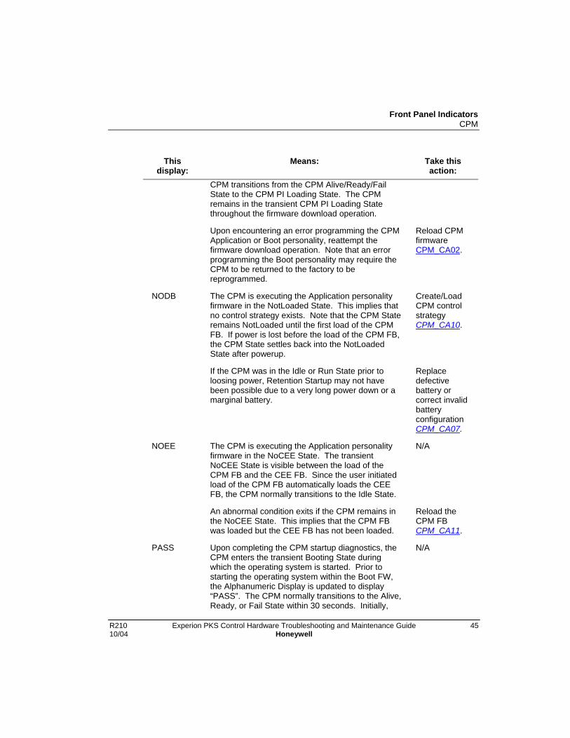
Front Panel IndicatorsCPM
R210 Experion PKS Control Hardware Troubleshooting and Maintenance Guide 4510/04 Honeywell
Thisdisplay:
Means: Take thisaction:
CPM transitions from the CPM Alive/Ready/FailState to the CPM PI Loading State. The CPMremains in the transient CPM PI Loading Statethroughout the firmware download operation.
Upon encountering an error programming the CPMApplication or Boot personality, reattempt thefirmware download operation. Note that an errorprogramming the Boot personality may require theCPM to be returned to the factory to bereprogrammed.
Reload CPMfirmwareCPM_CA02.
NODB The CPM is executing the Application personalityfirmware in the NotLoaded State. This implies thatno control strategy exists. Note that the CPM Stateremains NotLoaded until the first load of the CPMFB. If power is lost before the load of the CPM FB,the CPM State settles back into the NotLoadedState after powerup.
Create/LoadCPM controlstrategyCPM_CA10.
If the CPM was in the Idle or Run State prior toloosing power, Retention Startup may not havebeen possible due to a very long power down or amarginal battery.
Replacedefectivebattery orcorrect invalidbatteryconfigurationCPM_CA07.
NOEE The CPM is executing the Application personalityfirmware in the NoCEE State. The transientNoCEE State is visible between the load of theCPM FB and the CEE FB. Since the user initiatedload of the CPM FB automatically loads the CEEFB, the CPM normally transitions to the Idle State.
N/A
An abnormal condition exits if the CPM remains inthe NoCEE State. This implies that the CPM FBwas loaded but the CEE FB has not been loaded.
Reload theCPM FBCPM_CA11.
PASS Upon completing the CPM startup diagnostics, theCPM enters the transient Booting State duringwhich the operating system is started. Prior tostarting the operating system within the Boot FW,the Alphanumeric Display is updated to display“PASS”. The CPM normally transitions to the Alive,Ready, or Fail State within 30 seconds. Initially,
N/A

Front Panel IndicatorsCPM
46 Experion PKS Control Hardware Troubleshooting and Maintenance Guide R210Honeywell 10/04
Thisdisplay:
Means: Take thisaction:
ICP Communication is not active, but it is enabledprior to completion of the Booting State.
An abnormal condition exists if the CPM remains inthe Booting State for more than 30 seconds. Notethat if a RM is present in the chassis, the CPMremains in the Booting State while the RM performsits startup diagnostics.
Check the RMCPM_CA08.
RDY The CPM is executing the Boot personalityfirmware in the Ready State. A valid Applicationpersonality exists. ICP Communication is enabled.The CPM remains in the CPM Ready State until theuser either commands Application FW download orissues the Start command. The CPM transitions tothe CPM Loading State in the former case orreboots into the Run, Idle, NoCEE, NotLoaded orBackup State in the latter case, respectively.
Restart theCPMCPM_CA05.
RUN The CPM is executing the Application personalityfirmware in the Run State. This implies a controlstrategy is loaded and the control strategy in active.
N/A
Txxx Upon being released from reset, the CPM entersthe transient Testing State during which the CPMexecutes startup diagnostics. Prior to executingeach diagnostic, a test sequence number, “Txxx”, isposted to the Alphanumeric Display so that if a testfails or hangs, the Alphanumeric Display indicatesthe test that was in progress at the time of failure.The test of longest duration takes much less than30 seconds to complete.
N/A
An abnormal condition exists if the CPM remainsdisplaying the same Test Sequence Number formore than 30 seconds.
Interpret theCPM TestSequenceNumber Tableof CPM TestSequenceNumbers.
wait Once the new Application or Boot firmware isloaded, the CPM disappears from the ICPbackplane while the personality is programmed intoflash ROM. The CPM reboots within 30 seconds.
N/A

Front Panel IndicatorsCPM
R210 Experion PKS Control Hardware Troubleshooting and Maintenance Guide 4710/04 Honeywell
Thisdisplay:
Means: Take thisaction:
An abnormal condition exists if the CPM remainsdisplaying “wait” for more than 30 seconds.
Restart theCPMCPM_CA05.
WDT Indicates the CPM Watchdog Timer has timed-out. Recover fromCPMWatchdogTimer TimeoutCPM_CA13.
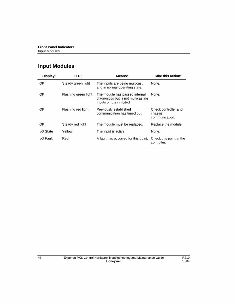
Front Panel IndicatorsInput Modules
48 Experion PKS Control Hardware Troubleshooting and Maintenance Guide R210Honeywell 10/04
Input Modules
Display: LED: Means: Take this action:
OK Steady green light The inputs are being multicastand in normal operating state.
None.
OK Flashing green light The module has passed internaldiagnostics but is not multicastinginputs or it is inhibited
None.
OK Flashing red light Previously establishedcommunication has timed out.
Check controller andchassiscommunication.
OK Steady red light The module must be replaced. Replace the module.
I/O State Yellow The input is active. None.
I/O Fault Red A fault has occurred for this point. Check this point at thecontroller.
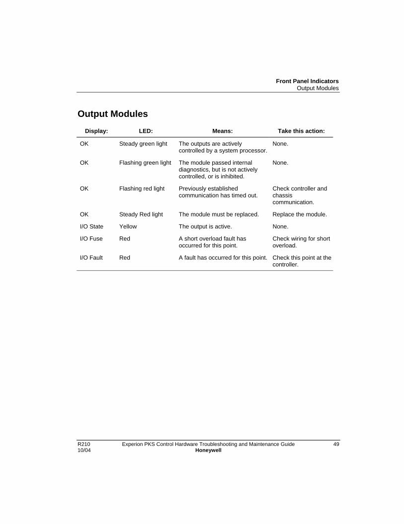
Front Panel IndicatorsOutput Modules
R210 Experion PKS Control Hardware Troubleshooting and Maintenance Guide 4910/04 Honeywell
Output Modules
Display: LED: Means: Take this action:
OK Steady green light The outputs are activelycontrolled by a system processor.
None.
OK Flashing green light The module passed internaldiagnostics, but is not activelycontrolled, or is inhibited.
None.
OK Flashing red light Previously establishedcommunication has timed out.
Check controller andchassiscommunication.
OK Steady Red light The module must be replaced. Replace the module.
I/O State Yellow The output is active. None.
I/O Fuse Red A short overload fault hasoccurred for this point.
Check wiring for shortoverload.
I/O Fault Red A fault has occurred for this point. Check this point at thecontroller.

Front Panel IndicatorsSerial Interface Modules
50 Experion PKS Control Hardware Troubleshooting and Maintenance Guide R210Honeywell 10/04
Serial Interface Modules
4-Character Display
Startup/Selftest Mode
ThisDisplay:
Means: Corrective Action:
Tnnn Selftest – Current Test Sequence Number. If the SIM stallswith one of thesenumbersdisplayed, replacethe SIM.
TEST Factory Test Mode. Entered on command orbecause the backplane test signal wasasserted.
Can be loaded.
PASS Completed Selftest. Attempting to executeBoot.
None.
ALIV Running in Boot; no personality is present. Can be loaded.
WDT (LED Green/Red)
Factory Test Mode Commanded WDT test –waiting for timeout interrupt. Health LED willturn from GREEN to RED upon WDT timeout.
None.
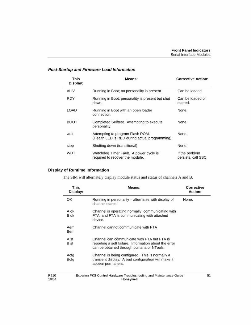
Front Panel IndicatorsSerial Interface Modules
R210 Experion PKS Control Hardware Troubleshooting and Maintenance Guide 5110/04 Honeywell
Post-Startup and Firmware Load Information
ThisDisplay:
Means: Corrective Action:
ALIV Running in Boot; no personality is present. Can be loaded.
RDY Running in Boot; personality is present but shutdown.
Can be loaded orstarted.
LOAD Running in Boot with an open loaderconnection.
None.
BOOT Completed Selftest. Attempting to executepersonality.
None.
wait Attempting to program Flash ROM.(Health LED is RED during actual programming)
None.
stop Shutting down (transitional) None.
WDT Watchdog Timer Fault. A power cycle isrequired to recover the module.
If the problempersists, call SSC.
Display of Runtime InformationThe SIM will alternately display module status and status of channels A and B.
ThisDisplay:
Means: CorrectiveAction:
OK Running in personality – alternates with display ofchannel states.
None.
A okB ok
Channel is operating normally, communicating withFTA, and FTA is communicating with attacheddevice.
AerrBerr
Channel cannot communicate with FTA
A stB st
Channel can communicate with FTA but FTA isreporting a soft failure. Information about the errorcan be obtained through pcmana or NTools.
AcfgBcfg
Channel is being configured. This is normally atransient display. A bad configuration will make itappear permanent.

Front Panel IndicatorsSerial Interface Modules
52 Experion PKS Control Hardware Troubleshooting and Maintenance Guide R210Honeywell 10/04
Display of Failure Information
When the CPM is in the Fail state, the alphanumeric display will alternate the numericfail code and ‘FAIL’.
ThisDisplay:
Means: Corrective Action:
FAILalternatingwith nnnn
Software error nnnn has occured. Running inBoot. Can be loaded, recovered or restarted.
A power cycle isrequired to recoverthe module.If the problempersists, contactSSC.
WDT Watchdog Timer Fault. A power cycle isrequired to recoverthe module.If the problempersists, contactSSC.
WDT (Let from Green to Red)
Factory Test Mode Commanded WDT test –waiting for timeout interrupt.
Health LED will turn from GREEN to REDupon WDT timeout.
None

Front Panel IndicatorsSerial Interface Modules
R210 Experion PKS Control Hardware Troubleshooting and Maintenance Guide 5310/04 Honeywell
Health IndicatorThe Health LED is used to indicate the general state of the module.
This Display: Means: Corrective Action:
OFF No power; significant fault. None
Solid RED During load it means programming the FlashROM.
Selftest in progress or failed – accompaniedby a test number in Alphanumeric display;Hardware Fault, unrecoverable WDTTimeout.
A power cycle isrequired to recoverthe module. If theproblem persists,contact SSC.
Flashing RED Fail State, running under software control.
AlternatingRED/GREEN
Factory Test Mode.
Solid GREEN OK – At leasst one I/O data connectionactive.
FlashingGREEN
During load it means getting ready to programFlash ROM.
During run, it means no active I/O connection.
Channel Activity IndicatorsThere is a status/activity indicator for each channel of A and B.
This Display: Means: CorrectiveAction:
OFF No activity – Alive
FlashingGREEN
Transmit or Receive in progress, but not normalcontinuous communications.
Brief GREENflash every0.5 sec
FTA is not present or not communicating – aretry is performed every 0.5 second.
Solid GREEN Normal communications with FTA producescontinuous illumination.
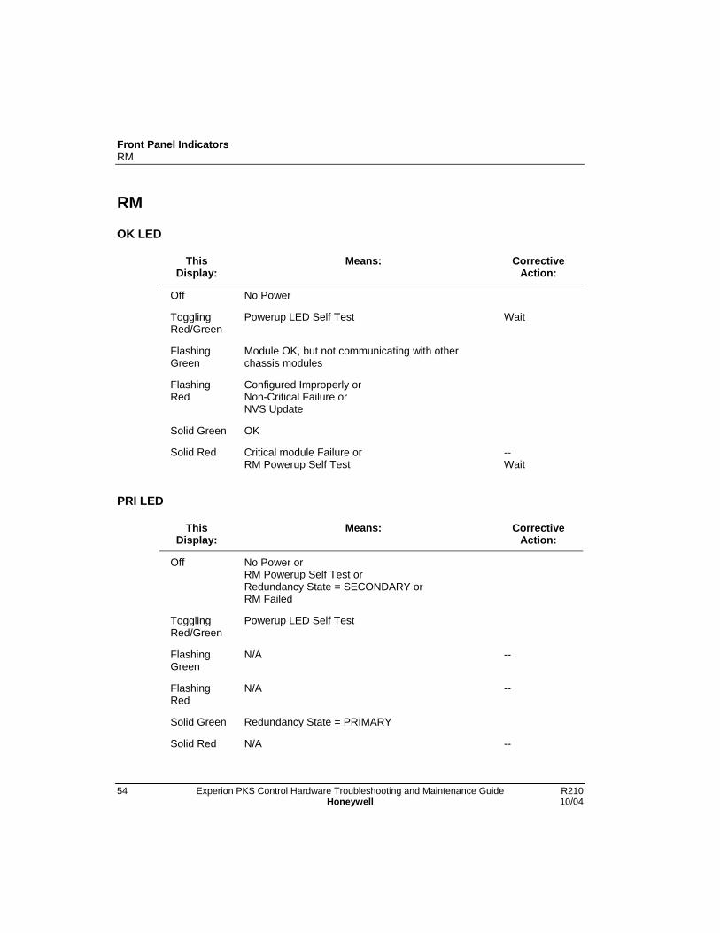
Front Panel IndicatorsRM
54 Experion PKS Control Hardware Troubleshooting and Maintenance Guide R210Honeywell 10/04
RM
OK LED
ThisDisplay:
Means: CorrectiveAction:
Off No Power
TogglingRed/Green
Powerup LED Self Test Wait
FlashingGreen
Module OK, but not communicating with otherchassis modules
FlashingRed
Configured Improperly orNon-Critical Failure orNVS Update
Solid Green OK
Solid Red Critical module Failure orRM Powerup Self Test
--Wait
PRI LED
ThisDisplay:
Means: CorrectiveAction:
Off No Power orRM Powerup Self Test orRedundancy State = SECONDARY orRM Failed
TogglingRed/Green
Powerup LED Self Test
FlashingGreen
N/A --
FlashingRed
N/A --
Solid Green Redundancy State = PRIMARY
Solid Red N/A --

Front Panel IndicatorsRM
R210 Experion PKS Control Hardware Troubleshooting and Maintenance Guide 5510/04 Honeywell
COM LED
ThisDisplay:
Means: CorrectiveAction:
Off No Power orRM Powerup Self Test
TogglingRed/Green
Powerup LED Self Test
FlashingGreen
No (or intermittent) partner connections.
FlashingRed
N/A --
Solid Green Normal partner communications.
Solid Red Partner connection occurred.

Front Panel IndicatorsRM
56 Experion PKS Control Hardware Troubleshooting and Maintenance Guide R210Honeywell 10/04
4-Character Display
Startup/Selftest Mode
ThisDisplay:
Means: CorrectiveAction:
(all pixelson)
Visual test. The display will flash twice to allow theuser to quickly check the condition of the display.
THnx RM startup self test, Phase I.
T - designates a startup test.
H - designates the Self Test subsystem.
n x – Numeric Subtest ID.
The “n” signifies a number. When this character isa number, the RM is executing test code out of itsflash ROM. Most of the tests are against the RM’sRAM.
The Subtest ID is presented at the start of a testand held only for the duration of a test. Most testsexecute too quickly for the operator to read thecode. However, should a test fail, the RM will tendto hold the display so the user can identify thefailed test.
TH** RM self test decompressing its executive code intoRAM, after which the RM will begin executing out ofRAM.
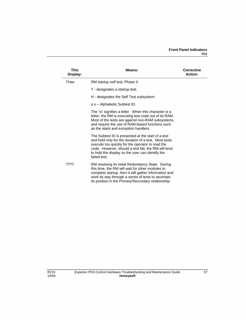
Front Panel IndicatorsRM
R210 Experion PKS Control Hardware Troubleshooting and Maintenance Guide 5710/04 Honeywell
ThisDisplay:
Means: CorrectiveAction:
THax RM startup self test, Phase II.
T - designates a startup test.
H - designates the Self Test subsystem.
a x – Alphabetic Subtest ID.
The “a” signifies a letter. When this character is aletter, the RM is executing test code out of its RAM.Most of the tests are against non-RAM subsystems,and require the use of RAM-based functions suchas the stack and exception handlers.
The Subtest ID is presented at the start of a testand held only for the duration of a test. Most testsexecute too quickly for the operator to read thecode. However, should a test fail, the RM will tendto hold the display so the user can identify thefailed test.
???? RM resolving its initial Redundancy State. Duringthis time, the RM will wait for other modules tocomplete startup, then it will gather information andwork its way through a series of tests to ascertainits position in the Primary/Secondary relationship.
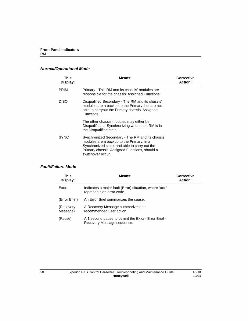
Front Panel IndicatorsRM
58 Experion PKS Control Hardware Troubleshooting and Maintenance Guide R210Honeywell 10/04
Normal/Operational Mode
ThisDisplay:
Means: CorrectiveAction:
PRIM Primary - This RM and its chassis’ modules areresponsible for the chassis’ Assigned Functions.
DISQ Disqualified Secondary - The RM and its chassis’modules are a backup to the Primary, but are notable to carryout the Primary chassis’ AssignedFunctions.
The other chassis modules may either beDisqualified or Synchronizing when then RM is inthe Disqualified state.
SYNC Synchronized Secondary - The RM and its chassis’modules are a backup to the Primary, in aSynchronized state, and able to carry out thePrimary chassis’ Assigned Functions, should aswitchover occur.
Fault/Failure Mode
ThisDisplay:
Means: CorrectiveAction:
Exxx Indicates a major fault (Error) situation, where “xxx”represents an error code.
(Error Brief) An Error Brief summarizes the cause.
(RecoveryMessage)
A Recovery Message summarizes therecommended user action.
(Pause) A 1 second pause to delimit the Exxx - Error Brief -Recovery Message sequence.
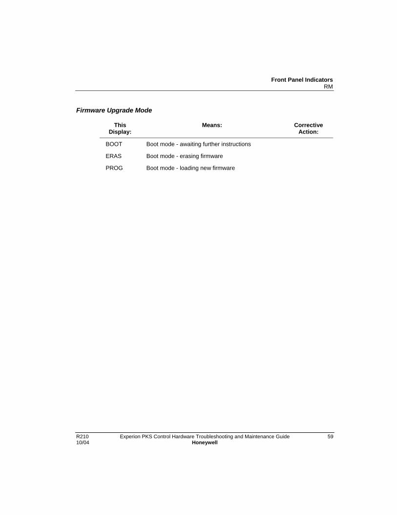
Front Panel IndicatorsRM
R210 Experion PKS Control Hardware Troubleshooting and Maintenance Guide 5910/04 Honeywell
Firmware Upgrade Mode
ThisDisplay:
Means: CorrectiveAction:
BOOT Boot mode - awaiting further instructions
ERAS Boot mode - erasing firmware
PROG Boot mode - loading new firmware

Front Panel IndicatorsIOLIM
60 Experion PKS Control Hardware Troubleshooting and Maintenance Guide R210Honeywell 10/04
IOLIM
4-Character Display and “OK” LED
The IOLIM has one four-character display and three two-color LEDs on its front panel.The LEDs provide Link 1 status, Link 2 status, and module health status (OK). Thefollowing table summarizes some typical indications for reference.
OK LED is . . . And, 4-CharacterDisplay shows . .
Then, IOLIM is . . .
Solid Red TEST Factory test mode
T### Executing hardware diagnostic tests(display shows T###, where ### isthe test number)
Solid Green BOOT Booting firmware
Flashing Green/off ALIV No application loaded
RDY Ready for firmware upgrade
LOAD Loading firmware
Solid Red PROG Downloaded firmware is beingprogrammed into Flash ROM
FAIL Failed
Solid Green ifsecondary issynchronized.Flashing green ifsecondary is notsynchronized.
BKUP Secondary IOLIM
Solid Green if thereare CDA connectionsto the module.Flashing green if noCDA.
NODB No database
NOEE IOLIM block loaded, IOLINK blocknot loaded.
OK IOLIM block loaded and running.

Front Panel IndicatorsIOLIM
R210 Experion PKS Control Hardware Troubleshooting and Maintenance Guide 6110/04 Honeywell
OK LED is . . . And, 4-CharacterDisplay shows . .
Then, IOLIM is . . .
OK – SF(display alternates OK
and SF)
IOLINK detects a soft failure.
LINK Status LEDs
Two LEDs indicate the status of Link A and Link B. The following table describespossible conditions.
If CHANNEL A or BLED is . . .
Condition
Solid Red IOLIM self test
Flashing Red Channel communications error
Solid Green Channel communications OK
Flashing Green Channel communications warning

Front Panel IndicatorsIOLIM
62 Experion PKS Control Hardware Troubleshooting and Maintenance Guide R210Honeywell 10/04
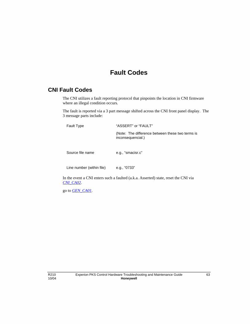
R210 Experion PKS Control Hardware Troubleshooting and Maintenance Guide 6310/04 Honeywell
Fault Codes
CNI Fault CodesThe CNI utilizes a fault reporting protocol that pinpoints the location in CNI firmwarewhere an illegal condition occurs.
The fault is reported via a 3 part message shifted across the CNI front panel display. The3 message parts include:
Fault Type “ASSERT” or “FAULT”
(Note: The difference between these two terms isinconsequencial.)
Source file name e.g., “smacisr.c”
Line number (within file) e.g., “0733”
In the event a CNI enters such a faulted (a.k.a. Asserted) state, reset the CNI viaCNI_CA02.
go to GEN_CA01.
Fault CodesCPM Fault Codes
64 Experion PKS Control Hardware Troubleshooting and Maintenance Guide R210Honeywell 10/04
CPM Fault Codes
Background
Upon detection of a hard fault or critical failure, the CPM reboots into the Fail State.Hardware permitting, ICP communications to the module is enabled. An “error block” isgenerated (at the time of failure) to store information useful in diagnosis following theoccurrence of a fault. The error block survives power cycles as long as no RAMparity/edac errors are introduced (i.e. single battery of proper voltage is present).
Each discernible type of detectable fault is assigned a unique faultcode. If the CPMgenerated fault code is not defined in one of the following subsections, perform thefollowing general corrective action. First, recover from the CPM Fail State CPM_CA04.If the problem persists, replace the CPM CPM_CA06.
0x0000
Description: The CPM faulted without generation of a fault code.
Cause: Software defect or memory corruption.
CorrectiveAction:
First, recover from the CPM Fail State CPM_CA04. If the problempersists, replace the CPM CPM_CA06.
0x0002
Description: The CPM encountered an unexpected Machine Check fatalexception.
Cause: Memory corruption.
CorrectiveAction:
First, recover from the CPM Fail State CPM_CA04. If the problempersists, replace the CPM CPM_CA06.
0x0003
Description: The CPM encountered an unexpected Data Access fatal exception.
Cause: Memory corruption.
CorrectiveAction:
First, recover from the CPM Fail State CPM_CA04. If the problempersists, replace the CPM CPM_CA06.

Fault CodesCPM Fault Codes
R210 Experion PKS Control Hardware Troubleshooting and Maintenance Guide 6510/04 Honeywell
0x0004
Description: The CPM encountered an unexpected Instruction Access fatalexception.
Cause: Unable to access ROM and/or memory corruption.
CorrectiveAction:
First, recover from the CPM Fail State CPM_CA04. If the problempersists, replace the CPM CPM_CA06.
0x0006
Description: The CPM encountered an unexpected Alignment fatal exception.
Cause: Memory corruption.
CorrectiveAction:
First, recover from the CPM Fail State CPM_CA04. If the problempersists, replace the CPM CPM_CA06.
0x0007
Description: The CPM encountered an unexpected Program fatal exception.
Cause: Memory corruption.
CorrectiveAction:
First, recover from the CPM Fail State CPM_CA04. If the problempersists, replace the CPM CPM_CA06.
0x0008
Description: The CPM encountered an unexpected Floating Point Unavailablefatal exception.
Cause: Memory corruption.
CorrectiveAction:
First, recover from the CPM Fail State CPM_CA04. If the problempersists, replace the CPM CPM_CA06.

Fault CodesCPM Fault Codes
66 Experion PKS Control Hardware Troubleshooting and Maintenance Guide R210Honeywell 10/04
0x000D
Description: The CPM encountered an unexpected Trace fatal exception.
Cause: Defective CPU (since this feature is only enabled in a developmentscenario).
CorrectiveAction:
Replace the CPM CPM_CA06.
0x0013
Description: The CPM encountered an unexpected Instruction AddressBreakpoint fatal exception.
Cause: Defective CPU (since this feature is only enabled in a developmentscenario).
CorrectiveAction:
Replace the CPM CPM_CA06.
0x0014
Description: The CPM encountered an unexpected System ManagementInterrupt fatal exception.
Cause: {1} Watchdog Timer timeout.
{2} ICP ASIC Fault signal asserted.
CorrectiveAction:
First, recover from the CPM Fail State CPM_CA04. If the problempersists, replace the CPM CPM_CA06.
0x0401
Description:
PLTCLLSInvalidCrashCodeRange
Cause: Software defect (i.e. impossible condition that should never occur).
CorrectiveAction:
Fault CodesCPM Fault Codes
R210 Experion PKS Control Hardware Troubleshooting and Maintenance Guide 6710/04 Honeywell
0x0402
Description:
PLTCLLSCantReserveCEEDB
Cause:
CorrectiveAction:
0x0403
Description:
PLTCLLSCantReleaseCEEDB
Cause:
CorrectiveAction:
0x0404
Description:
CEEUBTCantGetIdForStartUpTask
Cause:
CorrectiveAction:
0x0405
Description:
CEEUBTCantSendCompleteToStartUpTask
Cause:
CorrectiveAction:

Fault CodesCPM Fault Codes
68 Experion PKS Control Hardware Troubleshooting and Maintenance Guide R210Honeywell 10/04
0x0406
Description:
CEEUBTErrorOnWaitForStartUpTask
Cause:
CorrectiveAction:
0x0407
Description:
CEEUBTCantGetIdForCEEUBTask
Cause:
CorrectiveAction:
0x0408
Description:
CEEUBTCantGetPriorityForCEEUBTask
Cause:
CorrectiveAction:
0x0409
Description:
CEEBTCantGetIdForStartUpTask
Cause:
CorrectiveAction:

Fault CodesCPM Fault Codes
R210 Experion PKS Control Hardware Troubleshooting and Maintenance Guide 6910/04 Honeywell
0x040A
Description:
CEEBTCantSendCompleteToStartUpTask
Cause:
CorrectiveAction:
0x040B
Description:
CEEBTErrorOnWaitForStartUpTask
Cause:
CorrectiveAction:
0x040C
Description:
CEEBTCantSetUpCycleTimingEvent
Cause:
CorrectiveAction:
0x040D
Description:
CEEBTErrorOnWaitForFirstCycleTimingEvent
Cause:
CorrectiveAction:

Fault CodesCPM Fault Codes
70 Experion PKS Control Hardware Troubleshooting and Maintenance Guide R210Honeywell 10/04
0x040E
Description:
CEEBTErrorOnWaitForNthCycleTimingEvent
Cause:
CorrectiveAction:
0x040F
Description:
CEEBTCantGetIdForCEEBTask
Cause:
CorrectiveAction:
0x0410
Description:
CEEBTCantGetPriorityForCEEBTask
Cause:
CorrectiveAction:
0x0411
Description:
CEEBTCantCreateCEEFB
Cause:
CorrectiveAction:

Fault CodesCPM Fault Codes
R210 Experion PKS Control Hardware Troubleshooting and Maintenance Guide 7110/04 Honeywell
0x0412
Description:
CEEBTCantCreatePCMFB
Cause:
CorrectiveAction:
0x0413
Description:
CFCMFBMAssignXferInstSize
Cause:
CorrectiveAction:
0x0414
Description:
CFCMFBExecuteDFLOX
Cause:
CorrectiveAction:
0x0415
Description:
CFCMFBUnBindBlocks
Cause:
CorrectiveAction:
Fault CodesCPM Fault Codes
72 Experion PKS Control Hardware Troubleshooting and Maintenance Guide R210Honeywell 10/04
0x0416
Description:
CEEBTCantAllocateSchedulerMemory
Cause:
CorrectiveAction:
0x0417
Description:
CEEBTCantAllocateBlockManagerMemory
Cause:
CorrectiveAction:
0x0418
Description:
CEEBTCantAllocateConnectionManagerMemory
Cause:
CorrectiveAction:
0x0419
Description:
CEEBTCantCreatePhysicalPool
Cause:
CorrectiveAction:
Fault CodesCPM Fault Codes
R210 Experion PKS Control Hardware Troubleshooting and Maintenance Guide 7310/04 Honeywell
0x041A
Description:
CEEBTCantCreateMemoryManager
Cause:
CorrectiveAction:
0x041B
Description:
BMCantAccessRCOAMemory
Cause:
CorrectiveAction:
0x041C
Description:
CCLITCantGetIdForStartUpTask
Cause:
CorrectiveAction:
0x041D
Description:
CCLITCantSendCompleteToStartUpTask
Cause:
CorrectiveAction:

Fault CodesCPM Fault Codes
74 Experion PKS Control Hardware Troubleshooting and Maintenance Guide R210Honeywell 10/04
0x041E
Description:
CCLITErrorOnWaitForStartUpTask
Cause:
CorrectiveAction:
0x041F
Description:
CCLMBindCallOutWasCalled
Cause:
CorrectiveAction:
0x0420
Description:
CCLITMinorVersionChangeFailed
Cause:
CorrectiveAction:
0x0421
Description:
CEEBTCantAllocateBlockTypeManagerMemory
Cause:
CorrectiveAction:

Fault CodesCPM Fault Codes
R210 Experion PKS Control Hardware Troubleshooting and Maintenance Guide 7510/04 Honeywell
0x0422
Description:
CEEBTCantAllocateCCLManagerMemory
Cause:
CorrectiveAction:
0x0423
Description:
CCLITAcquireLibrariesFailed
Cause:
CorrectiveAction:
0x0424
Description:
CCLITCantGetIdForCEEBTask
Cause:
CorrectiveAction:
0x0425
Description:
CEEBTCantGetIdForCCLITask
Cause:
CorrectiveAction:

Fault CodesCPM Fault Codes
76 Experion PKS Control Hardware Troubleshooting and Maintenance Guide R210Honeywell 10/04
0x0426
Description:
CEEBTCantSendInitEventToCCLITask
Cause:
CorrectiveAction:
0x0427
Description:
CEEBTErrorOnWaitForCCLITask
Cause:
CorrectiveAction:
0x0428
Description:
CCLITUnloadLibrariesFailed
Cause:
CorrectiveAction:
0x0429
Description:
CEEBTCantSendEventToCCLITask
Cause:
CorrectiveAction:

Fault CodesCPM Fault Codes
R210 Experion PKS Control Hardware Troubleshooting and Maintenance Guide 7710/04 Honeywell
0x042A
Description:
CCLITCantGetIdForCEEUTask
Cause:
CorrectiveAction:
0x042B
Description:
CFCMFBCfInitialize
Cause:
CorrectiveAction:
0x042C
Description:
CEEUBTInvalidTaskIDForGuaranteedStore
Cause:
CorrectiveAction:
0x042D
Description:
ROLETCantGetROLETaskPriority
Cause:
CorrectiveAction:

Fault CodesExchange Block ERRCODE Fault Codes
78 Experion PKS Control Hardware Troubleshooting and Maintenance Guide R210Honeywell 10/04
0x042E
Description:
ROLETCantSetCCLITaskPriority
Cause:
CorrectiveAction:
0x042F
Description:
ROLETCantGetIdForCCLITask
Cause:
CorrectiveAction:
0x0430
Description:
ROLETCantSendEventToCCLITask
Cause:
CorrectiveAction:
0x0431
Description:
CEEUBTSharedRamDecodeFailure
Cause:
CorrectiveAction:
Exchange Block ERRCODE Fault Codes

Fault CodesExchange Block ERRCODE Fault Codes
R210 Experion PKS Control Hardware Troubleshooting and Maintenance Guide 7910/04 Honeywell
Description
Communication errors and errors reported by the target device are stored without beingmodified in the ERRCODE parameter of request type Exchange function blocks. All ofthe PCCC errors and some of the other errors are generated by the target device. Pleaserefer to the Allen-Bradley documentation for additional information about these errors.The fault codes for some common errors are listed below for convenient reference.
1
Name: CONNECTION_FAILED
Cause: A connection could not be established from the CPM to the targetdevice. Possible reasons for this error include:
• An invalid relative path was specified.
• A ControlNet cable on the path between the CPM and thetarget is broken or has been disconnected.
• The target device or an intermediate CNI on the path betweenthe CPM and the target is powered off.
• The specified maximum number of target devices has beenexceeded.
CorrectiveAction:
2
Name: INSUFFICIENT RESOURCE
Cause: There are insufficient resources in the CPM for this array block.
CorrectiveAction:
Make sure that the specified maximum number of request arrayblocks in the CPM has not been exceeded. Delete other arrayblocks that are no longer being used to free resources in the CPM.
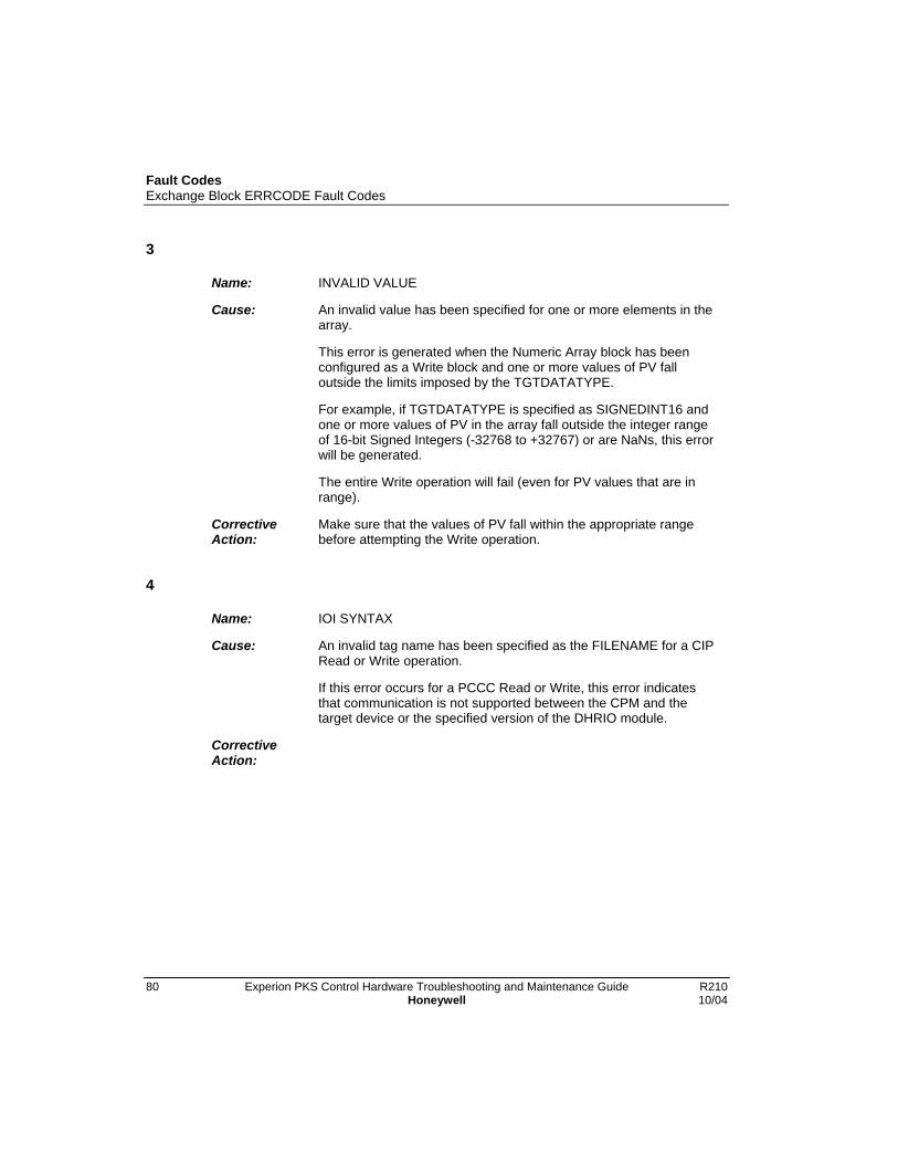
Fault CodesExchange Block ERRCODE Fault Codes
80 Experion PKS Control Hardware Troubleshooting and Maintenance Guide R210Honeywell 10/04
3
Name: INVALID VALUE
Cause: An invalid value has been specified for one or more elements in thearray.
This error is generated when the Numeric Array block has beenconfigured as a Write block and one or more values of PV falloutside the limits imposed by the TGTDATATYPE.
For example, if TGTDATATYPE is specified as SIGNEDINT16 andone or more values of PV in the array fall outside the integer rangeof 16-bit Signed Integers (-32768 to +32767) or are NaNs, this errorwill be generated.
The entire Write operation will fail (even for PV values that are inrange).
CorrectiveAction:
Make sure that the values of PV fall within the appropriate rangebefore attempting the Write operation.
4
Name: IOI SYNTAX
Cause: An invalid tag name has been specified as the FILENAME for a CIPRead or Write operation.
If this error occurs for a PCCC Read or Write, this error indicatesthat communication is not supported between the CPM and thetarget device or the specified version of the DHRIO module.
CorrectiveAction:
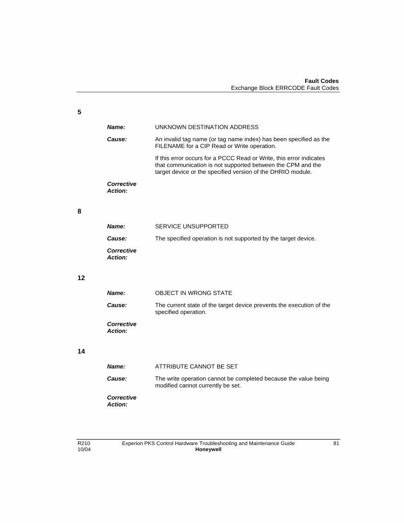
Fault CodesExchange Block ERRCODE Fault Codes
R210 Experion PKS Control Hardware Troubleshooting and Maintenance Guide 8110/04 Honeywell
5
Name: UNKNOWN DESTINATION ADDRESS
Cause: An invalid tag name (or tag name index) has been specified as theFILENAME for a CIP Read or Write operation.
If this error occurs for a PCCC Read or Write, this error indicatesthat communication is not supported between the CPM and thetarget device or the specified version of the DHRIO module.
CorrectiveAction:
8
Name: SERVICE UNSUPPORTED
Cause: The specified operation is not supported by the target device.
CorrectiveAction:
12
Name: OBJECT IN WRONG STATE
Cause: The current state of the target device prevents the execution of thespecified operation.
CorrectiveAction:
14
Name: ATTRIBUTE CANNOT BE SET
Cause: The write operation cannot be completed because the value beingmodified cannot currently be set.
CorrectiveAction:
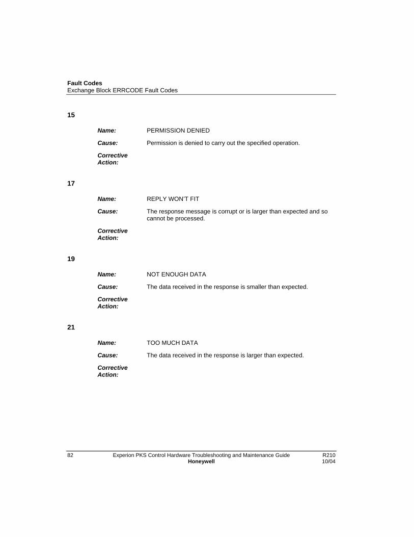
Fault CodesExchange Block ERRCODE Fault Codes
82 Experion PKS Control Hardware Troubleshooting and Maintenance Guide R210Honeywell 10/04
15
Name: PERMISSION DENIED
Cause: Permission is denied to carry out the specified operation.
CorrectiveAction:
17
Name: REPLY WON’T FIT
Cause: The response message is corrupt or is larger than expected and socannot be processed.
CorrectiveAction:
19
Name: NOT ENOUGH DATA
Cause: The data received in the response is smaller than expected.
CorrectiveAction:
21
Name: TOO MUCH DATA
Cause: The data received in the response is larger than expected.
CorrectiveAction:

Fault CodesExchange Block ERRCODE Fault Codes
R210 Experion PKS Control Hardware Troubleshooting and Maintenance Guide 8310/04 Honeywell
31
Name: CONNECTION RELATED FAILURE
Cause: There is a connection-related failure due to communicationproblems in the path between the CPM and the target device.
CorrectiveAction:
34
Name: INVALID REPLY
Cause: The data size or data type of the response is incompatible with thetype of array block being used for CIP access. Note that the FlagArray Block can only access Binary (BOOL) files, the Numeric Arrayblock can only access Integer (SINT, INT, DINT) and SinglePrecision Floating Point (REAL) files, and the Text Array block canonly access ASCII files.
CorrectiveAction:
255
Name: Wrong Data
Cause: There is something wrong in your data that you are writing.
CorrectiveAction:
Chedk for NaN.
512
Name: PCCC Error
Cause: Cannot guarantee delivery, link layer timed out or received a NAK.
CorrectiveAction:
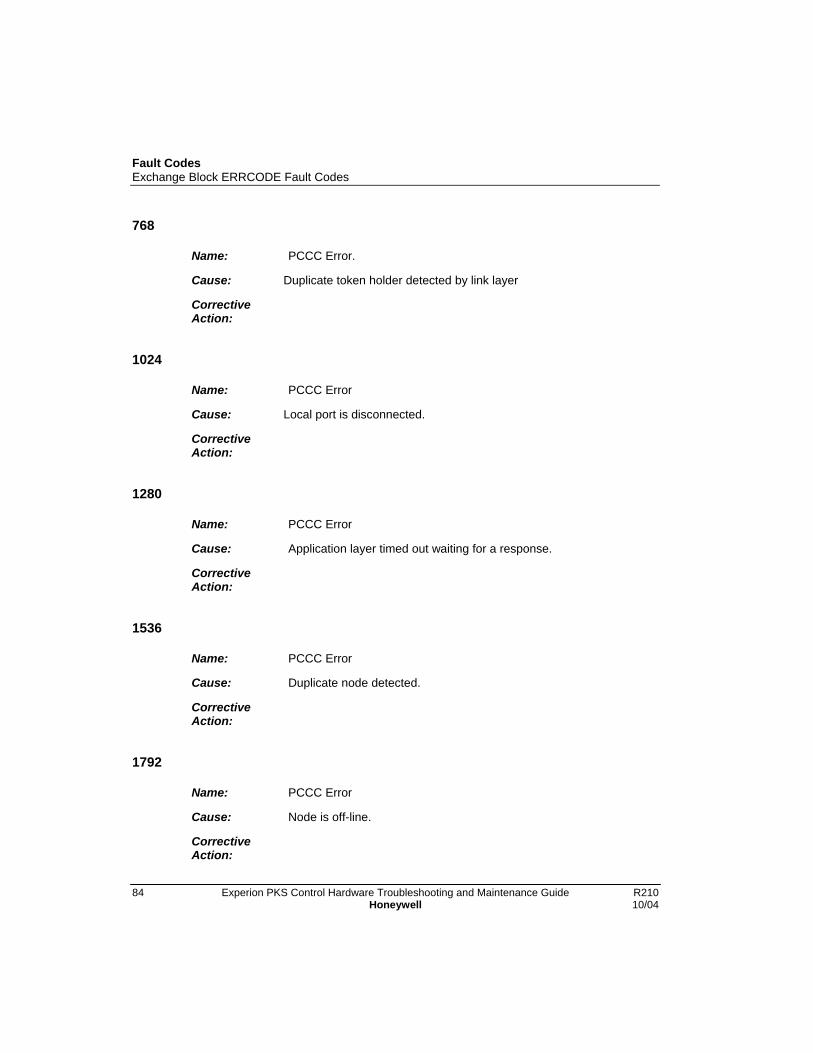
Fault CodesExchange Block ERRCODE Fault Codes
84 Experion PKS Control Hardware Troubleshooting and Maintenance Guide R210Honeywell 10/04
768
Name: PCCC Error.
Cause: Duplicate token holder detected by link layer
CorrectiveAction:
1024
Name: PCCC Error
Cause: Local port is disconnected.
CorrectiveAction:
1280
Name: PCCC Error
Cause: Application layer timed out waiting for a response.
CorrectiveAction:
1536
Name: PCCC Error
Cause: Duplicate node detected.
CorrectiveAction:
1792
Name: PCCC Error
Cause: Node is off-line.
CorrectiveAction:
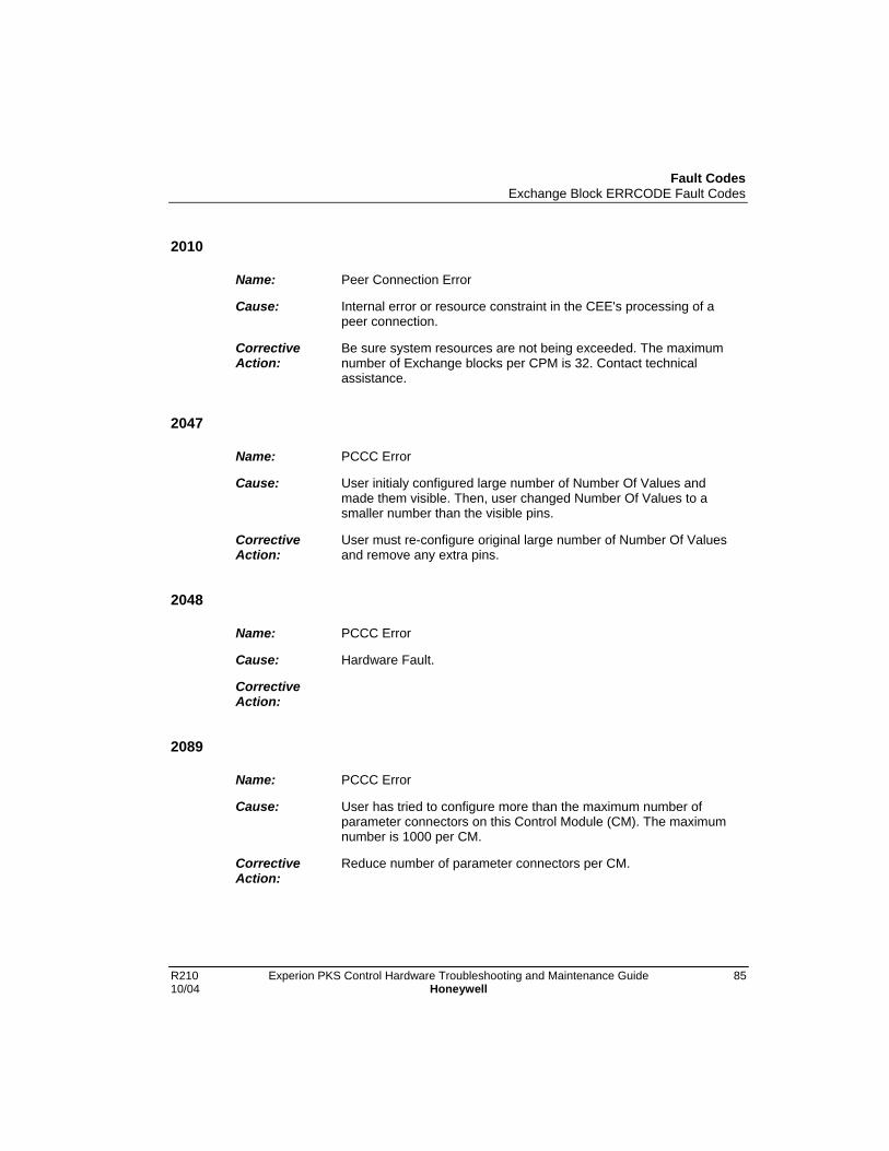
Fault CodesExchange Block ERRCODE Fault Codes
R210 Experion PKS Control Hardware Troubleshooting and Maintenance Guide 8510/04 Honeywell
2010
Name: Peer Connection Error
Cause: Internal error or resource constraint in the CEE's processing of apeer connection.
CorrectiveAction:
Be sure system resources are not being exceeded. The maximumnumber of Exchange blocks per CPM is 32. Contact technicalassistance.
2047
Name: PCCC Error
Cause: User initialy configured large number of Number Of Values andmade them visible. Then, user changed Number Of Values to asmaller number than the visible pins.
CorrectiveAction:
User must re-configure original large number of Number Of Valuesand remove any extra pins.
2048
Name: PCCC Error
Cause: Hardware Fault.
CorrectiveAction:
2089
Name: PCCC Error
Cause: User has tried to configure more than the maximum number ofparameter connectors on this Control Module (CM). The maximumnumber is 1000 per CM.
CorrectiveAction:
Reduce number of parameter connectors per CM.
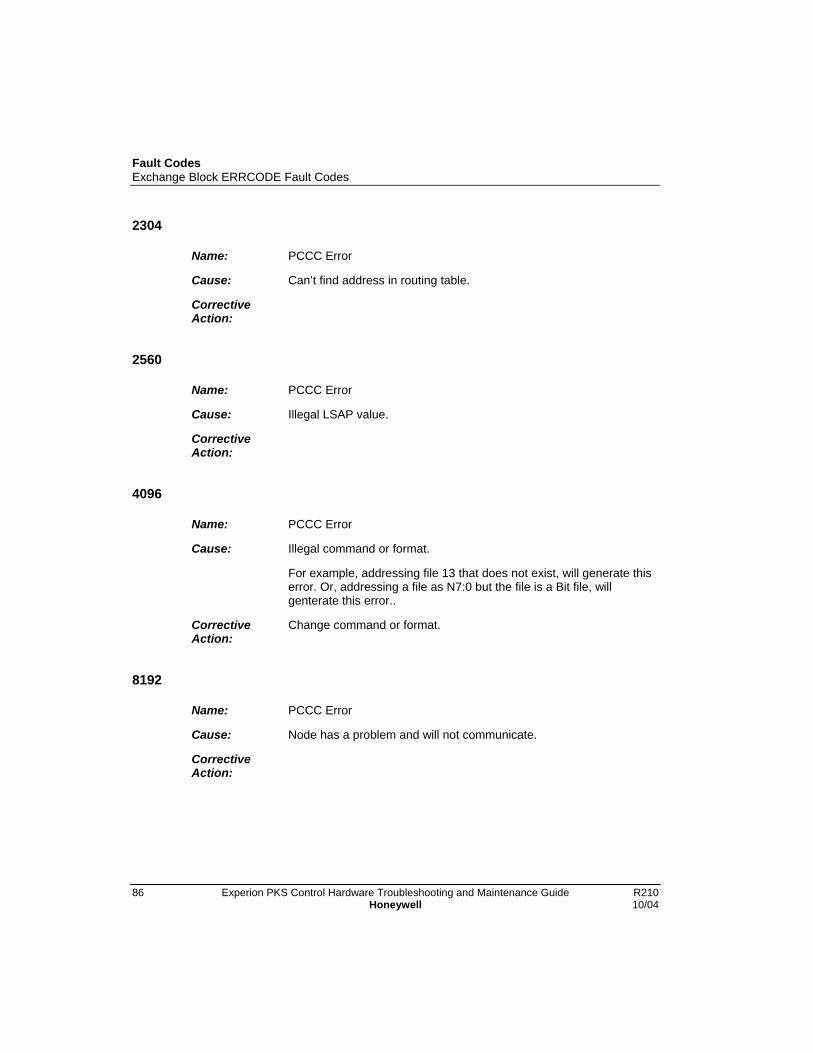
Fault CodesExchange Block ERRCODE Fault Codes
86 Experion PKS Control Hardware Troubleshooting and Maintenance Guide R210Honeywell 10/04
2304
Name: PCCC Error
Cause: Can’t find address in routing table.
CorrectiveAction:
2560
Name: PCCC Error
Cause: Illegal LSAP value.
CorrectiveAction:
4096
Name: PCCC Error
Cause: Illegal command or format.
For example, addressing file 13 that does not exist, will generate thiserror. Or, addressing a file as N7:0 but the file is a Bit file, willgenterate this error..
CorrectiveAction:
Change command or format.
8192
Name: PCCC Error
Cause: Node has a problem and will not communicate.
CorrectiveAction:
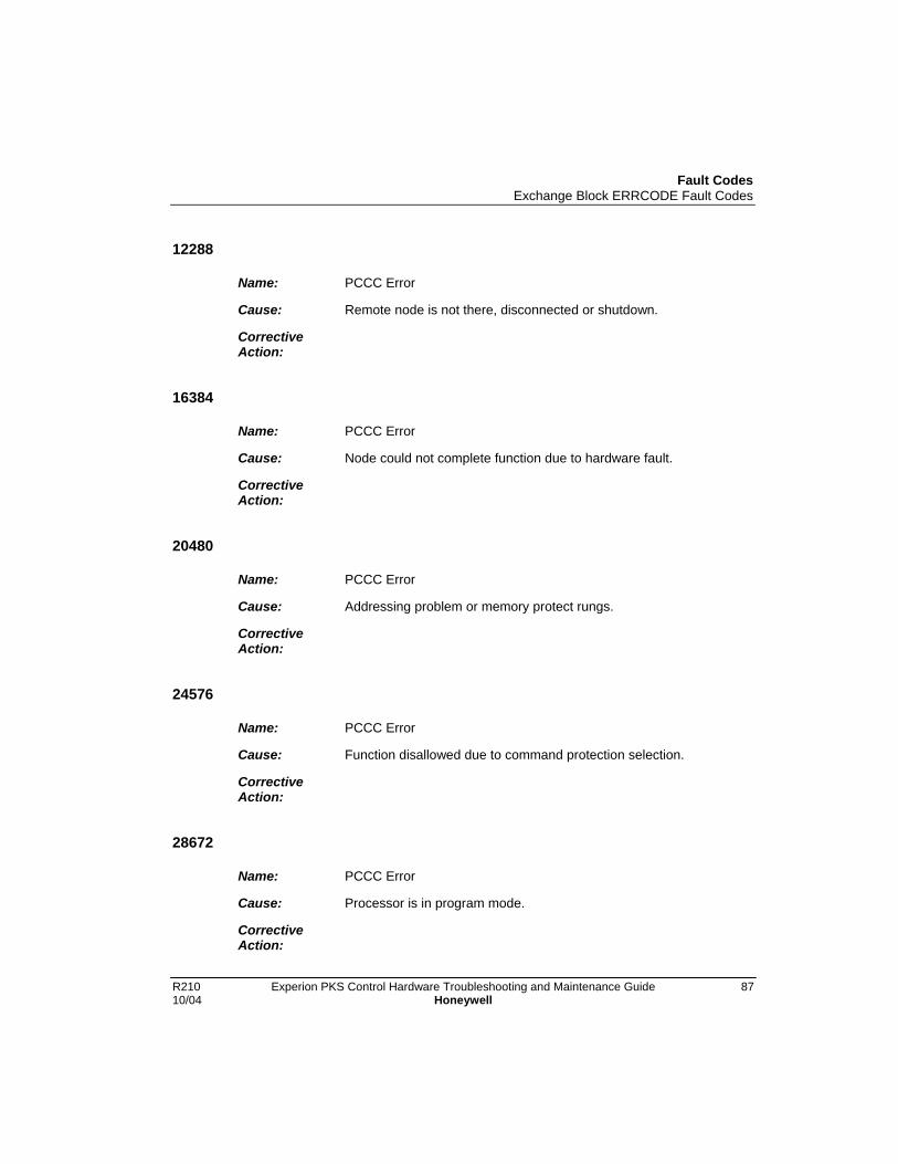
Fault CodesExchange Block ERRCODE Fault Codes
R210 Experion PKS Control Hardware Troubleshooting and Maintenance Guide 8710/04 Honeywell
12288
Name: PCCC Error
Cause: Remote node is not there, disconnected or shutdown.
CorrectiveAction:
16384
Name: PCCC Error
Cause: Node could not complete function due to hardware fault.
CorrectiveAction:
20480
Name: PCCC Error
Cause: Addressing problem or memory protect rungs.
CorrectiveAction:
24576
Name: PCCC Error
Cause: Function disallowed due to command protection selection.
CorrectiveAction:
28672
Name: PCCC Error
Cause: Processor is in program mode.
CorrectiveAction:

Fault CodesExchange Block ERRCODE Fault Codes
88 Experion PKS Control Hardware Troubleshooting and Maintenance Guide R210Honeywell 10/04
32768
Name: PCCC Error
Cause: Compatibility mode file missing or communication zone problem.
CorrectiveAction:
36864
Name: PCCC Error
Cause: Remote node cannot buffer command.
CorrectiveAction:
45056
Name: PCCC Error
Cause: Remote node problem, due to download.
CorrectiveAction:
49152
Name: PCCC Error
Cause: Cannot execute command, due to active IPBs.
CorrectiveAction:
53248
Name: PCCC Error
Cause: Cannot route request.
CorrectiveAction:
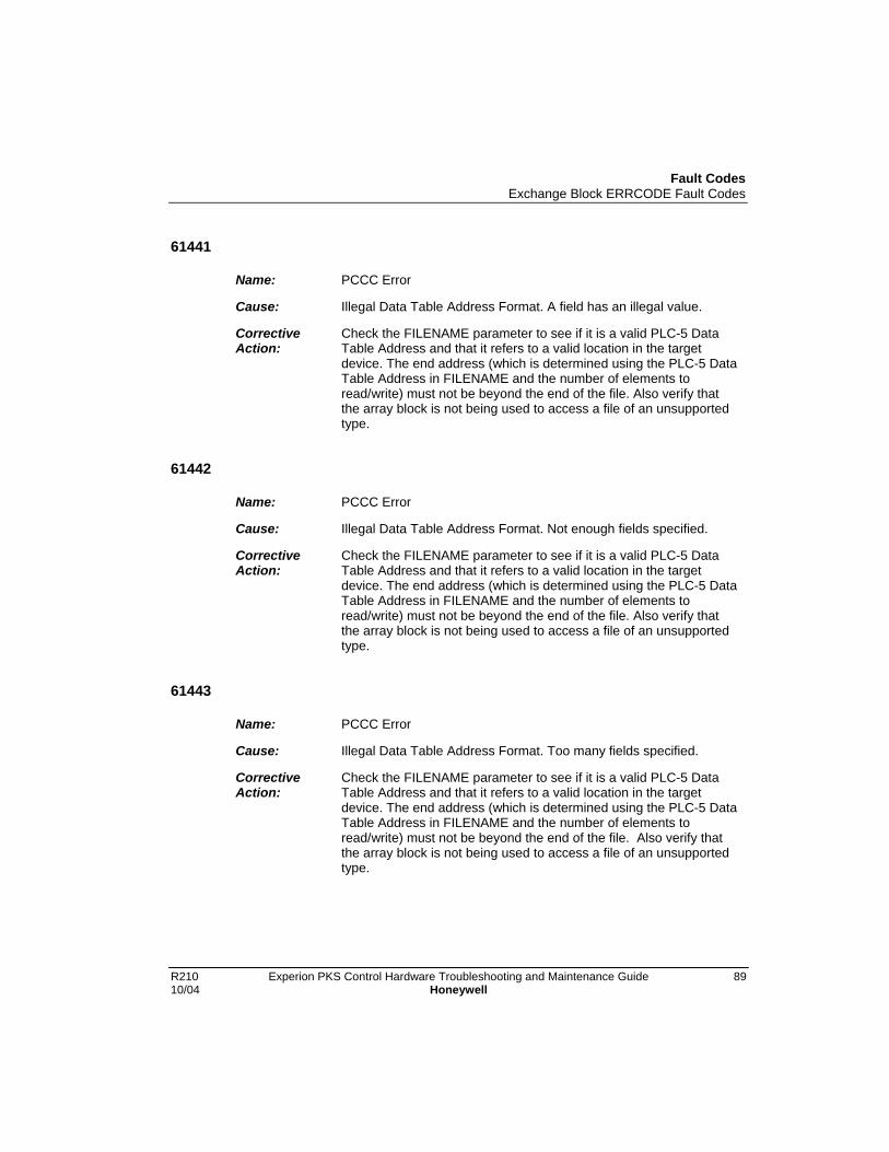
Fault CodesExchange Block ERRCODE Fault Codes
R210 Experion PKS Control Hardware Troubleshooting and Maintenance Guide 8910/04 Honeywell
61441
Name: PCCC Error
Cause: Illegal Data Table Address Format. A field has an illegal value.
CorrectiveAction:
Check the FILENAME parameter to see if it is a valid PLC-5 DataTable Address and that it refers to a valid location in the targetdevice. The end address (which is determined using the PLC-5 DataTable Address in FILENAME and the number of elements toread/write) must not be beyond the end of the file. Also verify thatthe array block is not being used to access a file of an unsupportedtype.
61442
Name: PCCC Error
Cause: Illegal Data Table Address Format. Not enough fields specified.
CorrectiveAction:
Check the FILENAME parameter to see if it is a valid PLC-5 DataTable Address and that it refers to a valid location in the targetdevice. The end address (which is determined using the PLC-5 DataTable Address in FILENAME and the number of elements toread/write) must not be beyond the end of the file. Also verify thatthe array block is not being used to access a file of an unsupportedtype.
61443
Name: PCCC Error
Cause: Illegal Data Table Address Format. Too many fields specified.
CorrectiveAction:
Check the FILENAME parameter to see if it is a valid PLC-5 DataTable Address and that it refers to a valid location in the targetdevice. The end address (which is determined using the PLC-5 DataTable Address in FILENAME and the number of elements toread/write) must not be beyond the end of the file. Also verify thatthe array block is not being used to access a file of an unsupportedtype.

Fault CodesExchange Block ERRCODE Fault Codes
90 Experion PKS Control Hardware Troubleshooting and Maintenance Guide R210Honeywell 10/04
61444
Name: PCCC Error
Cause: Illegal Data Table Address Format. Symbol not found.
CorrectiveAction:
Check type.
61445
Name: PCCC Error
Cause: Illegal Data Table Address Format. Symbol is zero or greater thanthe number of characters supported by the target device.
CorrectiveAction:
Check the FILENAME parameter to see if it is a valid PLC-5 DataTable Address and that it refers to a valid location in the targetdevice. The end address (which is determined using the PLC-5 DataTable Address in FILENAME and the number of elements toread/write) must not be beyond the end of the file. Also verify thatthe array block is not being used to access a file of an unsupportedtype.
61446
Name: PCCC Error
Cause: Illegal Address. Address does not exist, or does not point tosomething usable by this command.
CorrectiveAction:
Check the FILENAME parameter to see if it is a valid PLC-5 DataTable Address and that it refers to a valid location in the targetdevice. The end address (which is determined using the PLC-5 DataTable Address in FILENAME and the number of elements toread/write) must not be beyond the end of the file. Also verify thatthe array block is not being used to access a file of an unsupportedtype.

Fault CodesExchange Block ERRCODE Fault Codes
R210 Experion PKS Control Hardware Troubleshooting and Maintenance Guide 9110/04 Honeywell
61447
Name: PCCC Error:
Cause: Illegal size. File is wrong size. Address is past end of file.
CorrectiveAction:
Check the FILENAME parameter to see if it is a valid PLC-5 DataTable Address and that it refers to a valid location in the targetdevice. The end address (which is determined using the PLC-5 DataTable Address in FILENAME and the number of elements toread/write) must not be beyond the end of the file. Also verify thatthe array block is not being used to access a file of an unsupportedtype.
61448
Name: PCCC Error
Cause: Cannot complete request.Situation changed (file size, for example)during operation.
CorrectiveAction:
61449
Name: PCCC Error:
Cause: Data or file too large. Memory is unavailable.
CorrectiveAction:
61450
Name: PCCC Error:
Cause: Request is too large. Transaction size plus word address is toolarge.
CorrectiveAction:
Fault CodesExchange Block ERRCODE Fault Codes
92 Experion PKS Control Hardware Troubleshooting and Maintenance Guide R210Honeywell 10/04
61451
Name: PCCC Error
Cause: Access is denied, privilege violation.
CorrectiveAction:
61452
Name: PCCC Error
Cause: Resource is not available. Condition cannot be generated.
CorrectiveAction:
61453
Name: PCCC Error
Cause: Resource is already available. Condition already exists.
CorrectiveAction:
61454
Name: PCCC Error
Cause: Command cannot be executed.
CorrectiveAction:
61455
Name: PCCC Error:
Cause: Overflow. Histogram overflow.
CorrectiveAction:

Fault CodesExchange Block ERRCODE Fault Codes
R210 Experion PKS Control Hardware Troubleshooting and Maintenance Guide 9310/04 Honeywell
61456
Name: PCCC Error
Cause: No access.
CorrectiveAction:
61457
Name: PCCC Error
Cause: Illegal data type information.
CorrectiveAction:
Verify that the array block is not being used to access a file of anunsupported type.
61458
Name: PCCC Error:
Cause: Invalid parameter. Invalid data in search or command block.
CorrectiveAction:
61459
Name: PCCC Error
Cause: Address reference exists to deleted area.
CorrectiveAction:
61460
Name: PCCC Error
Cause: Command execution failure for unknown reason.
CorrectiveAction:
Fault CodesExchange Block ERRCODE Fault Codes
94 Experion PKS Control Hardware Troubleshooting and Maintenance Guide R210Honeywell 10/04
61461
Name: PCCC Error
Cause: Data conversion error.
CorrectiveAction:
61462
Name: PCCC Error
Cause: The scanner is not able to communicate with a 1771 rack adapter.
CorrectiveAction:
This could be due to the scanner not scanning, the selected adapternot being scanned, the adapter not responding, or an invalidrequest.
61463
Name: PCCC Error
Cause: The adapter is not able to communicate with the module.
CorrectiveAction:
61464
Name: PCCC Error
Cause: The 1771 module response was not valid (size, checksum, etc.).
CorrectiveAction:
Fault CodesExchange Block ERRCODE Fault Codes
R210 Experion PKS Control Hardware Troubleshooting and Maintenance Guide 9510/04 Honeywell
61465
Name: PCCC Error
Cause: Duplicated Label.
CorrectiveAction:
61466
Name: PCCC Error
Cause: File is open – another node owns it.
CorrectiveAction:
61467
Name: PCCC Error
Cause: Another node is the program owner.
CorrectiveAction:
61468
Name: PCCC Error
Cause: Disk file is write protected or otherwise inaccessible.
CorrectiveAction:
61469
Name: PCCC Error
Cause: Disk file is being used by another application, update not performed.
CorrectiveAction:
Fault CodesExchange Block ERRCODE Fault Codes
96 Experion PKS Control Hardware Troubleshooting and Maintenance Guide R210Honeywell 10/04
61470
Name: PCCC Error
Cause: Data Table Element Protection violation.
CorrectiveAction:
61471
Name: PCCC Error
Cause: Unable to execute command due to a temporary internal condition inthe target device.
CorrectiveAction:
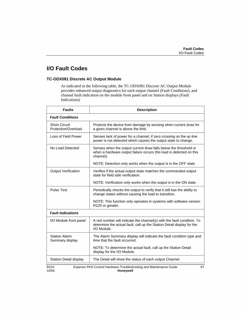
Fault CodesI/O Fault Codes
R210 Experion PKS Control Hardware Troubleshooting and Maintenance Guide 9710/04 Honeywell
I/O Fault Codes
TC-ODX081 Discrete AC Output Module
As indicated in the following table, the TC-ODX081 Discrete AC Output Moduleprovides enhanced output diagnostics for each output channel (Fault Conditions), andchannel fault indication on the module front panel and on Station displays (FaultIndications)
Faults Description
Fault Conditions
Short CircuitProtection/Overload
Protects the device from damage by sensing when current draw fora given channel is above the limit.
Loss of Field Power Senses lack of power for a channel, if zero crossing on the ac-linepower is not detected which causes the output state to change.
No Load Detected Senses when the output current draw falls below the threshold orwhen a hardware output failure occurs (No load is detected on thischannel).
NOTE: Detection only works when the output is in the OFF state.
Output Verification Verifies if the actual output state matches the commanded outputstate for field side verification.
NOTE: Verification only works when the output is in the ON state.
Pulse Test Periodically checks the output to verify that it still has the ability tochange states without causing the load to transition.
NOTE: This function only operates in systems with software versionR120 or greater.
Fault Indications
I/O Module front panel A red number will indicate the channel(s) with the fault condition. Todetermine the actual fault, call up the Station Detail display for theI/O Module.
Station AlarmSummary display
The Alarm Summary display will indicate the fault condition type andtime that the fault occurred.
NOTE: To determine the actual fault, call up the Station Detaildisplay for the I/O Module.
Station Detail display The Detail will show the status of each output Channel.

Fault CodesRM Fault Codes
98 Experion PKS Control Hardware Troubleshooting and Maintenance Guide R210Honeywell 10/04
RM Fault Codes
About fault code format
The fault code is a 4 character alphanumeric string. Valid characters are [0-9,A-Z],except [S, O]. The first character is always ‘E’. The second character indicates thesubsystem in which the error was detected. The third character indicates the subsystemfunction or group of functions in which the error was detected. The fourth characterenumerates the specific error.
Each subsystem within the RM is assigned a range of fault codes as listed in thefollowing table.
Range Object Firmware Directory
E 0 _ _ Backup Control Object /bcoObj
E 1 _ _ OS Board Support Package /bsp1.1
E 2 _ _ Chassis Profile Object /chpObj
E 3 _ _ Coordinated System Time Object /cstObj
E 4 _ _ Device Object /devObj
E 5 _ _ Extended Device Object /edoObj
E 6 _ _ Event Log Object /eloObj
E 7 _ _ Backup Communications Object /iSBMcomm
E 8 _ _ ICP toolkit /icptk
E 9 _ _ Indicator Device Driver /ind
E A _ _ RM State Machine (JABBA) /jabba
E B _ _ Event Log Device Driver /ogDrv
E C _ _ Object Communications /objComm
E D _ _ Wall Clock Time Object /wctObj
E E _ _ Non-Maskable Interrupt Service Routine /nmiIsr
E F _ _ Non-Volatile Storage Object /nvsObj
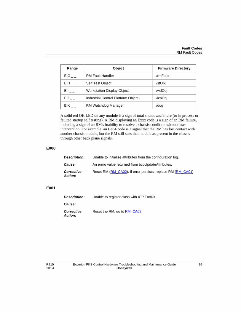
Fault CodesRM Fault Codes
R210 Experion PKS Control Hardware Troubleshooting and Maintenance Guide 9910/04 Honeywell
Range Object Firmware Directory
E G _ _ RM Fault Handler /rmFault
E H _ _ Self Test Object /stObj
E I _ _ Workstation Display Object /wdObj
E J _ _ Industrial Control Platform Object /icpObj
E K _ _ RM Watchdog Manager /dog
A solid red OK LED on any module is a sign of total shutdown/failure (or in process orfaulted startup self testing). A RM displaying an Exxx code is a sign of an RM failure,including a sign of an RM's inability to resolve a chassis condition without userintervention. For example, an E054 code is a signal that the RM has lost contact withanother chassis module, but the RM still sees that module as present in the chassisthrough other back plane signals.
E000
Description: Unable to initialize attributes from the configuration log.
Cause: An errno value returned from bcoUpdateAttributes.
CorrectiveAction:
Reset RM (RM_CA02). If error persists, replace RM (RM_CA01).
E001
Description: Unable to register class with ICP Toolkit.
Cause:
CorrectiveAction:
Reset the RM, go to RM_CA02.

Fault CodesRM Fault Codes
100 Experion PKS Control Hardware Troubleshooting and Maintenance Guide R210Honeywell 10/04
E010
Description: Unable to post event to message queue.
Cause: • An errno value returned from msgQSend.
• An event which was to be posted.
CorrectiveAction:
Reset the RM, go to RM_CA02.
E020
Description: Unable to read from incoming event message queue.
Cause: An errno value returned from msgQReceive.
CorrectiveAction:
Reset the RM, go to RM_CA02.
E021
Description: RM is in invalid state to perform a chassis state change with thepartner going first
Cause: A new state requested.
CorrectiveAction:
Reset the RM, go to RM_CA02.
E022
Description: Invalid value for state change coordination order.
Cause: State change coordination order.
CorrectiveAction:
Reset the RM, go to RM_CA02.

Fault CodesRM Fault Codes
R210 Experion PKS Control Hardware Troubleshooting and Maintenance Guide 10110/04 Honeywell
E023
Description: Unable to start watchdog timer used to wait for switchover phasingto complete.
Cause: An errno value returned from wdStart.
CorrectiveAction:
Reset the RM, go to RM_CA02.
E024
Description: Invalid event sent to the backup control object.
Cause: Event type.
CorrectiveAction:
Reset the RM, go to RM_CA02.
E025
Description: Unable to update attributes from the configuration log.
Cause: An errno value returned from bcoUpdateAttributes.
CorrectiveAction:
Reset (RM_CA02) or replace (RM_CA01) RM when convenient.
E026
Description: Unable to write display position to configuration log.
Cause: An errno value returned from cfgWriteDisplayPosition.
CorrectiveAction:
Reset (RM_CA02) or replace (RM_CA01) RM when convenient.
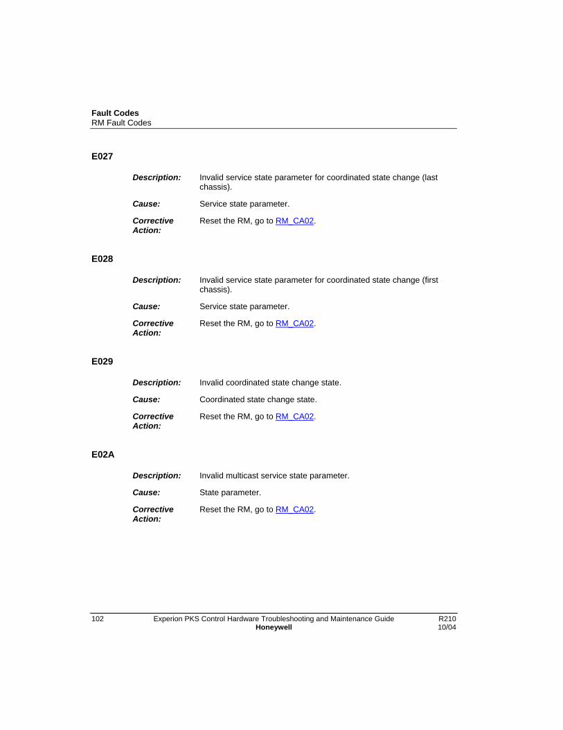
Fault CodesRM Fault Codes
102 Experion PKS Control Hardware Troubleshooting and Maintenance Guide R210Honeywell 10/04
E027
Description: Invalid service state parameter for coordinated state change (lastchassis).
Cause: Service state parameter.
CorrectiveAction:
Reset the RM, go to RM_CA02.
E028
Description: Invalid service state parameter for coordinated state change (firstchassis).
Cause: Service state parameter.
CorrectiveAction:
Reset the RM, go to RM_CA02.
E029
Description: Invalid coordinated state change state.
Cause: Coordinated state change state.
CorrectiveAction:
Reset the RM, go to RM_CA02.
E02A
Description: Invalid multicast service state parameter.
Cause: State parameter.
CorrectiveAction:
Reset the RM, go to RM_CA02.
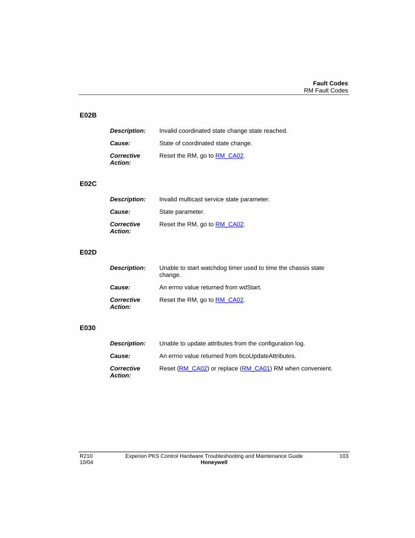
Fault CodesRM Fault Codes
R210 Experion PKS Control Hardware Troubleshooting and Maintenance Guide 10310/04 Honeywell
E02B
Description: Invalid coordinated state change state reached.
Cause: State of coordinated state change.
CorrectiveAction:
Reset the RM, go to RM_CA02.
E02C
Description: Invalid multicast service state parameter.
Cause: State parameter.
CorrectiveAction:
Reset the RM, go to RM_CA02.
E02D
Description: Unable to start watchdog timer used to time the chassis statechange.
Cause: An errno value returned from wdStart.
CorrectiveAction:
Reset the RM, go to RM_CA02.
E030
Description: Unable to update attributes from the configuration log.
Cause: An errno value returned from bcoUpdateAttributes.
CorrectiveAction:
Reset (RM_CA02) or replace (RM_CA01) RM when convenient.

Fault CodesRM Fault Codes
104 Experion PKS Control Hardware Troubleshooting and Maintenance Guide R210Honeywell 10/04
E031
Description: Unable to open module to RM portion of multicast connection.
Cause:
CorrectiveAction:
None.
E032
Description: The slot number value for a module opening module to RM portionof multicast connection exceeds largest possible slot number.
Cause:
CorrectiveAction:
None.
E033
Description: Unable to open module to RM portion of multicast connection.
Cause:
CorrectiveAction:
None.
E034
Description: The slot number value for a module opening module to RM portionof multicast connection exceeds largest possible slot number.
Cause:
CorrectiveAction:
None.

Fault CodesRM Fault Codes
R210 Experion PKS Control Hardware Troubleshooting and Maintenance Guide 10510/04 Honeywell
E035
Description: Unable to open connection made to the backup control object fromanother module (not the multicast connection).
Cause:
CorrectiveAction:
None.
E036
Description: Unable to close connection made to the backup control object fromanother module.
Cause: An errno value returned from objCommTargClose.
CorrectiveAction:
None.
E037
Description: Unable to send message to the backup control object event handlermessage queue.
Cause: An errno value returned from msgQSend.
CorrectiveAction:
Reset the RM, go to RM_CA02.
E038
Description: Unknown state change request from partner RM.
Cause:
CorrectiveAction:
Reset the RM, go to RM_CA02.
Fault CodesRM Fault Codes
106 Experion PKS Control Hardware Troubleshooting and Maintenance Guide R210Honeywell 10/04
E039
Description: Unable to allocate a response buffer for a state change requestservice.
Cause:
CorrectiveAction:
None.
E03A
Description: The response routine was NULL for the state change requestservice.
Cause:
CorrectiveAction:
Reset the RM, go to RM_CA02.
E03a
Description: Buffer could not be allocated for Fwd_Close_Reply on multicastconnection.
Cause:
CorrectiveAction:
None.
E03B
Description: Unable to prepare response buffer for initiate qualification servicerequest.
Cause:
CorrectiveAction:
None.

Fault CodesRM Fault Codes
R210 Experion PKS Control Hardware Troubleshooting and Maintenance Guide 10710/04 Honeywell
E03b
Description: There is no specified response routine to which to forward theFwd_Close_Reply buffer.
Cause:
CorrectiveAction:
Reset the RM, go to RM_CA02.
E03C
Description: The response routine was NULL for the initiate qualification servicerequest.
Cause:
CorrectiveAction:
Reset the RM, go to RM_CA02.
E03D
Description: Unable to prepare response buffer for the initiate switchover servicerequest.
Cause:
CorrectiveAction:
None.
E03E
Description: The response routine was NULL for the initiate switchover servicerequest.
Cause:
CorrectiveAction:
Reset the RM, go to RM_CA02.

Fault CodesRM Fault Codes
108 Experion PKS Control Hardware Troubleshooting and Maintenance Guide R210Honeywell 10/04
E03F
Description: Unable to start watchdog timer used to delay switchover request.
Cause: An errno value returned from wdStart.
CorrectiveAction:
Reset the RM, go to RM_CA02.
E03G
Description: Unable to prepare response buffer for the coordinated switchoverservice request.
Cause:
CorrectiveAction:
None.
E03H
Description: The response routine was NULL for the coordinated switchoverservice request.
Cause:
CorrectiveAction:
Reset the RM, go to RM_CA02.
E03I
Description: Unable to prepare response buffer for the report event servicerequest.
Cause:
CorrectiveAction:
None.

Fault CodesRM Fault Codes
R210 Experion PKS Control Hardware Troubleshooting and Maintenance Guide 10910/04 Honeywell
E03J
Description: The response routine was NULL for the report event servicerequest.
Cause:
CorrectiveAction:
Reset the RM, go to RM_CA02.
E03K
Description: Unable to prepare response buffer for the become primary servicerequest.
Cause:
CorrectiveAction:
None.
E03L
Description: The response routine was NULL for the become primary servicerequest.
Cause:
CorrectiveAction:
Reset the RM, go to RM_CA02.
E03M
Description: Unable to start watchdog timer used to delay become primaryrequest.
Cause: An errno value returned from wdStart.
CorrectiveAction:
Reset the RM, go to RM_CA02.

Fault CodesRM Fault Codes
110 Experion PKS Control Hardware Troubleshooting and Maintenance Guide R210Honeywell 10/04
E03N
Description: Unable to prepare response buffer for the disqualify secondaryservice request.
Cause:
CorrectiveAction:
None.
E03P
Description: Unable to send message to the backup control object event handlermessage queue.
Cause: An errno value returned from msgQSend.
CorrectiveAction:
Reset the RM, go to RM_CA02.
E03Q
Description: Unable to send message to the delayed service request handlermessage queue.
Cause: An errno value returned from msgQSend.
CorrectiveAction:
None.
E03R
Description: Unable to send message to the delayed service request handlermessage queue.
Cause: An errno value returned from msgQSend.
CorrectiveAction:
None.

Fault CodesRM Fault Codes
R210 Experion PKS Control Hardware Troubleshooting and Maintenance Guide 11110/04 Honeywell
E03T
Description: Unable to send message to the backup control object event handlermessage queue.
Cause: An errno value returned from msgQSend.
CorrectiveAction:
Reset the RM, go to RM_CA02.
E03U
Description: The response routine was NULL for the disqualify secondary servicerequest
Cause:
CorrectiveAction:
Reset the RM, go to RM_CA02.
E03V
Description: Unable to send message to the delayed service request handlermessage queue.
Cause: An errno value returned from msgQSend.
CorrectiveAction:
None.
E03W
Description: The appTable indicates that connection being closed uses non-ICP(Industrial Control Platform) Port.
Cause: • bcoObjTargAppHandle.
• appTable[bcoObjTargAppHandle].port
CorrectiveAction:
None.
Fault CodesRM Fault Codes
112 Experion PKS Control Hardware Troubleshooting and Maintenance Guide R210Honeywell 10/04
E03X
Description: The bcoLinkConsumerTable indicates that connection has alreadybeen closed
Cause: • UcmmReceiveSlotNum (slot in which module closingconnection resides).
• bcoLinkConsumerTable[ucmmReceiveSlotNum].
CorrectiveAction:
None.
E03Y
Description: Link consumer could not be freed (does not exist)
Cause: • UcmmReceiveSlotNum (slot in which module closingconnection resides).
• bcoLinkConsumerTable[ucmmReceiveSlotNum].
CorrectiveAction:
None.
E03Z
Description: Transport could not be restarted following removal of link consumer.
Cause:
CorrectiveAction:
None.
E040
Description: Unable to write autoqualification state to the configuration log.
Cause:
CorrectiveAction:
Reset ( RM_CA02) or replace the RM (RM_CA01).
Fault CodesRM Fault Codes
R210 Experion PKS Control Hardware Troubleshooting and Maintenance Guide 11310/04 Honeywell
E041
Description: Unable to write autoqualification option to the configuration log.
Cause:
CorrectiveAction:
Reset ( RM_CA02) or replace the RM (RM_CA01).
E042
Description: Unable to prepare response buffer for set single attribute servicerequest (autoqualification option attribute).
Cause:
CorrectiveAction:
None.
E043
Description: The response routine was NULL for set single attribute servicerequest (autoqualification option attribute).
Cause:
CorrectiveAction:
Reset the RM, go to RM_CA02.
E044
Description: Unable to write program command recognition attribute to theconfiguration log.
Cause:
CorrectiveAction:
Reset ( RM_CA02) or replace the RM (RM_CA01)..

Fault CodesRM Fault Codes
114 Experion PKS Control Hardware Troubleshooting and Maintenance Guide R210Honeywell 10/04
E045
Description: Unable to prepare response buffer for set single attribute servicerequest (program command recognition attribute).
Cause:
CorrectiveAction:
None.
E046
Description: The response routine was NULL for set single attribute servicerequest (program command recognition attribute).
Cause:
CorrectiveAction:
Reset the RM, go to RM_CA02.
E047
Description: Unable to prepare response buffer for set single attribute servicerequest (password scope attribute).
Cause:
CorrectiveAction:
None.
E048
Description: The response routine was NULL for set single attribute servicerequest (password scope attribute).
Cause:
CorrectiveAction:
Reset the RM, go to RM_CA02.

Fault CodesRM Fault Codes
R210 Experion PKS Control Hardware Troubleshooting and Maintenance Guide 11510/04 Honeywell
E049
Description: Unable to write display position attribute to the configuration log.
Cause:
CorrectiveAction:
Reset ( RM_CA02) or replace the RM (RM_CA01).
E04A
Description: Unable to prepare response buffer for set single attribute servicerequest (display position attribute).
Cause:
CorrectiveAction:
None.
E04B
Description: The response routine was NULL for set single attribute servicerequest (display position attribute).
Cause:
CorrectiveAction:
Reset the RM, go to RM_CA02.
E04C
Description: Unable to write autoqualification state to the configuration log.
Cause:
CorrectiveAction:
Reset ( RM_CA02) or replace the RM (RM_CA01).

Fault CodesRM Fault Codes
116 Experion PKS Control Hardware Troubleshooting and Maintenance Guide R210Honeywell 10/04
E04D
Description: Unable to write autoqualification state to the configuration log.
Cause:
CorrectiveAction:
Reset ( RM_CA02) or replace the RM (RM_CA01).
E050
Description: An invalid port number has been associated with the multicastconnection.
Cause:
CorrectiveAction:
None.
E051
Description: Attempting to delete a link consumer which has already beendeleted (or never allocated).
Cause:
CorrectiveAction:
None.
E052
Description: Unable to delete link consumer.
Cause:
CorrectiveAction:
None.

Fault CodesRM Fault Codes
R210 Experion PKS Control Hardware Troubleshooting and Maintenance Guide 11710/04 Honeywell
E053
Description: Unable to restart server transport for multicast connection after oneof the link consumers timed-out.
Cause:
CorrectiveAction:
None.
E054
Description: Unable to restart server transport for multicast connection after oneof the link consumers timed-out.
The RM requires operator assistance. It has encountered a situationwhere another chassis module is not responding to Redundancystatus queries but is still responding to low level backplane queries.This error can occur anytime after the RM completes Startup SelfTest.
If this RM was hosting a Primary with a Synchronized Secondary, aswitchover will occur.
If this RM was hosting a Synchronized Secondary, all otherfunctional chassis modules will enter a Disqualified Secondary state.
Cause: • Bitmap of redundancy compliant modules in chassis(determined by pinging).
• Slot number of module not responding, but the module is stillresponding to low level backplane interface queries("pings").
CorrectiveAction:
Reset offending module and the RM.
If the identity of the other module is not obvious from displays orchassis indicators, see the RM Event Log, where and E054 faultshould be recorded. The Data 2 field of that event record will specifythe slot number of the module that triggered the fault.
Go to RM_CA02.

Fault CodesRM Fault Codes
118 Experion PKS Control Hardware Troubleshooting and Maintenance Guide R210Honeywell 10/04
E060
Description: Invalid event received on connection.
Cause: Event received.
CorrectiveAction:
None.
E07A
Description: Invalid multicast service state parameter.
Cause: State parameter.
CorrectiveAction:
Reset the RM, go to RM_CA02.
E070
Description: Invalid multicast service state parameter.
Cause: State parameter.
CorrectiveAction:
Reset the RM, go to RM_CA02.
E071
Description: Invalid coordinated state change state reached.
Cause: State parameter.
CorrectiveAction:
Reset the RM, go to RM_CA02.
E072
Description: Invalid multicast service state parameter.
Cause: State parameter.
CorrectiveAction:
Reset the RM, go to RM_CA02.
Fault CodesRM Fault Codes
R210 Experion PKS Control Hardware Troubleshooting and Maintenance Guide 11910/04 Honeywell
E073
Description: Unknown error code received.
Cause: Error code.
CorrectiveAction:
None.
E074
Description: Unknown extended error code received.
Cause: Extended error code.
CorrectiveAction:
None.
E075
Description: Invalid extended error size.
Cause: Extended error size.
CorrectiveAction:
None.
E076
Description: Unknown error code received..
Cause: Error code.
CorrectiveAction:
None.
E077
Description: Invalid service response code received.
Cause: Service response code.
CorrectiveAction:
None.

Fault CodesRM Fault Codes
120 Experion PKS Control Hardware Troubleshooting and Maintenance Guide R210Honeywell 10/04
E078
Description: Invalid multicast service state parameter.
Cause: State parameter.
CorrectiveAction:
Reset the RM, go to RM_CA02.
E079
Description: Invalid coordinated state change state reached.
Cause: State of coordinated state change.
CorrectiveAction:
Reset the RM, go to RM_CA02.
E080
Description: Invalid service parameter for qualifcation service response.
Cause: Service parameter.
CorrectiveAction:
None.
E090
Description: Invalid service state parameter for coordinated state change (lastchassis).
Cause: Service state parameter.
CorrectiveAction:
Reset the RM, go to RM_CA02.

Fault CodesRM Fault Codes
R210 Experion PKS Control Hardware Troubleshooting and Maintenance Guide 12110/04 Honeywell
E091
Description: Invalid service state parameter for coordinated state change (firstchassis).
Cause: Service state parameter.
CorrectiveAction:
Reset the RM, go to RM_CA02.
E092
Description: Invalid coordinated state change state.
Cause: Coordinated state change state.
CorrectiveAction:
Reset the RM, go to RM_CA02.
E093
Description: Invalid multicast service state.
Cause: Multicast service state.
CorrectiveAction:
Reset the RM, go to RM_CA02.
E0A0
Description: New state is invalid.
Cause: New state.
CorrectiveAction:
Reset the RM, go to RM_CA02.

Fault CodesRM Fault Codes
122 Experion PKS Control Hardware Troubleshooting and Maintenance Guide R210Honeywell 10/04
E0A1
Description: New state is invalid (for last chassis coordinated state change state).
Cause: New state.
CorrectiveAction:
Reset the RM, go to RM_CA02.
E0A2
Description: New state is invalid (for first chassis coordinated state changestate).
Cause: New state.
CorrectiveAction:
Reset the RM, go to RM_CA02.
E0A3
Description: Invalid coordinated state change state.
Cause: Coordinated state change state.
CorrectiveAction:
Reset the RM, go to RM_CA02.
E0A4
Description: New state is invalid (for last chassis coordinated state change state).
Cause: New state.
CorrectiveAction:
Reset the RM, go to RM_CA02.

Fault CodesRM Fault Codes
R210 Experion PKS Control Hardware Troubleshooting and Maintenance Guide 12310/04 Honeywell
E0A5
Description: New state is invalid (for first chassis coordinated state changestate).
Cause: New state.
CorrectiveAction:
Reset the RM, go to RM_CA02.
E0A6
Description: Invalid coordinated state change state.
Cause: Coordinated state change state.
CorrectiveAction:
Reset the RM, go to RM_CA02.
E0A7
Description: Status of multicast connection makes it impossible to send statenotification.
Cause: Status of multicast connection.
CorrectiveAction:
Reset the RM, go to RM_CA02.
E0A8
Description: Unable to start watchdog timer used to time the chassis statechange.
Cause: An errno value returned from wdStart.
CorrectiveAction:
Reset the RM, go to RM_CA02.
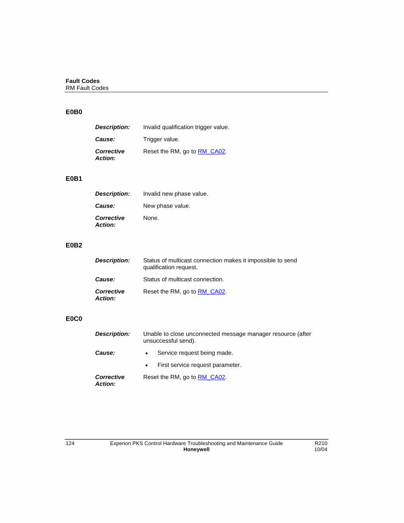
Fault CodesRM Fault Codes
124 Experion PKS Control Hardware Troubleshooting and Maintenance Guide R210Honeywell 10/04
E0B0
Description: Invalid qualification trigger value.
Cause: Trigger value.
CorrectiveAction:
Reset the RM, go to RM_CA02.
E0B1
Description: Invalid new phase value.
Cause: New phase value.
CorrectiveAction:
None.
E0B2
Description: Status of multicast connection makes it impossible to sendqualification request.
Cause: Status of multicast connection.
CorrectiveAction:
Reset the RM, go to RM_CA02.
E0C0
Description: Unable to close unconnected message manager resource (afterunsuccessful send).
Cause: • Service request being made.
• First service request parameter.
CorrectiveAction:
Reset the RM, go to RM_CA02.

Fault CodesRM Fault Codes
R210 Experion PKS Control Hardware Troubleshooting and Maintenance Guide 12510/04 Honeywell
E0C1
Description: Unable to close unconnected message manager resource (aftersuccessful send and response).
Cause: • Service request being made.
• First service request parameter.
CorrectiveAction:
Reset the RM, go to RM_CA02.
E0C2
Description: Unable to close unconnected message manager resource (aftermaximum retries reached).
Cause: • Service request being made.
• First service request parameter.
CorrectiveAction:
Reset the RM, go to RM_CA02.
E0C3
Description: Unable to close unconnected message manager resource (afterunsuccessful send and unsuccessful attempt to recycle the resourcefor a retry).
Cause: • Service request being made.
• First service request parameter.
CorrectiveAction:
Reset the RM, go to RM_CA02.
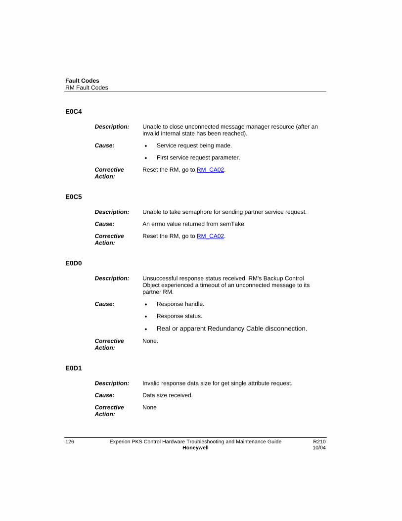
Fault CodesRM Fault Codes
126 Experion PKS Control Hardware Troubleshooting and Maintenance Guide R210Honeywell 10/04
E0C4
Description: Unable to close unconnected message manager resource (after aninvalid internal state has been reached).
Cause: • Service request being made.
• First service request parameter.
CorrectiveAction:
Reset the RM, go to RM_CA02.
E0C5
Description: Unable to take semaphore for sending partner service request.
Cause: An errno value returned from semTake.
CorrectiveAction:
Reset the RM, go to RM_CA02.
E0D0
Description: Unsuccessful response status received. RM's Backup ControlObject experienced a timeout of an unconnected message to itspartner RM.
Cause: • Response handle.
• Response status.
• Real or apparent Redundancy Cable disconnection.
CorrectiveAction:
None.
E0D1
Description: Invalid response data size for get single attribute request.
Cause: Data size received.
CorrectiveAction:
None

Fault CodesRM Fault Codes
R210 Experion PKS Control Hardware Troubleshooting and Maintenance Guide 12710/04 Honeywell
E0D2
Description: Invalid response service for get single attribute request.
Cause: Response service code.
CorrectiveAction:
None
E0D3
Description: Get single attribute request was unsuccessful.
Cause: Response general status code.
CorrectiveAction:
None
E0D4
Description: Invalid partner state returned in get single attribute request.
Cause: Partner state.
CorrectiveAction:
Reset the RM, go to RM_CA02.
E0D5
Description: Invalid response data size for coordinated state change request.
Cause: Data size received.
CorrectiveAction:
None.
E0D6
Description: Invalid response service for coordinated state change request.
Cause: Response service code.
CorrectiveAction:
None.

Fault CodesRM Fault Codes
128 Experion PKS Control Hardware Troubleshooting and Maintenance Guide R210Honeywell 10/04
E0D7
Description: Coordinated state change request was unsuccessful.
Cause: Response general status code.
CorrectiveAction:
None.
E0D8
Description: Invalid response data size for coordinated switchover request.
Cause: Data size received.
CorrectiveAction:
None.
E0D9
Description: Invalid response service for coordinated switchover request.
Cause: Response service code.
CorrectiveAction:
None.
E0DA
Description: Coordinated switchover request was unsuccessful.
Cause: Response general status code.
CorrectiveAction:
None.
E0DB
Description: An invalid coordinated switchover state has been reached.
Cause: Coordinated switchover state.
CorrectiveAction:
Reset the RM, go to RM_CA02.

Fault CodesRM Fault Codes
R210 Experion PKS Control Hardware Troubleshooting and Maintenance Guide 12910/04 Honeywell
E0DC
Description: Invalid service request response receieved.
Cause: Response handle.
CorrectiveAction:
Reset the RM, go to RM_CA02.
E0E0
Description: New switchover phase is invalid.
Cause: New switchover phase.
CorrectiveAction:
Reset the RM, go to RM_CA02.
E0E1
Description: Status of multicast connection makes it impossible to sendswitchover request.
Cause: Status of multicast connection.
CorrectiveAction:
Reset the RM, go to RM_CA02.
E0E2
Description: The ICP ASIC timer interrupt is not working properly.
Cause:
CorrectiveAction:
Reset the RM, go to RM_CA02.

Fault CodesRM Fault Codes
130 Experion PKS Control Hardware Troubleshooting and Maintenance Guide R210Honeywell 10/04
E0F0
Description: Invalid parameter for service request being delayed.
Cause: Service request being delayed.
CorrectiveAction:
Reset the RM, go to RM_CA02.
E0G0
Description: Invalid new state requested.
Cause: New state value.
CorrectiveAction:
Reset the RM, go to RM_CA02.
E0H0
Description: Unable to update attributes from configuration log.
Cause: An errno value returned by bcoUpdateAttributes.
CorrectiveAction:
Reset ( RM_CA02) or replace the RM (RM_CA01).
E0I0
Description: Tried to send more than one request at a time to the partner RM.
Cause: • Service request number of offending service.
• First service parameter.
CorrectiveAction:
Reset the RM, go to RM_CA02.

Fault CodesRM Fault Codes
R210 Experion PKS Control Hardware Troubleshooting and Maintenance Guide 13110/04 Honeywell
E0I1
Description: Out of necessary resources to send partner request.
Cause: • Service request number.
• First service parameter
CorrectiveAction:
Reset the RM, go to RM_CA02.
E0I2
Description: Invalid service request.
Cause: • Service request number.
• First service parameter
CorrectiveAction:
Reset the RM, go to RM_CA02.
E0I3
Description: Invalid response state during request.
Cause: • Service request number.
• First service parameter
CorrectiveAction:
Reset the RM, go to RM_CA02.
E0I4
Description: No client resources available to send request.
Cause: • Service request number.
• First service parameter
CorrectiveAction:
Reset the RM, go to RM_CA02.

Fault CodesRM Fault Codes
132 Experion PKS Control Hardware Troubleshooting and Maintenance Guide R210Honeywell 10/04
E0I5
Description: No receive descriptor available for the response.
Cause: • Service request number.
• First service parameter
CorrectiveAction:
Reset the RM, go to RM_CA02.
E0I6
Description: No transmit descriptor available for the request.
Cause: • Service request number.
• First service parameter
CorrectiveAction:
Reset the RM, go to RM_CA02.
E0I7
Description: No combuf available for the response.
Cause: • Service request number.
• First service parameter
CorrectiveAction:
Reset the RM, go to RM_CA02.
E0I8
Description: A bad unconnected message manager handle was used.
Cause: • Service request number.
• First service parameter
CorrectiveAction:
Reset the RM, go to RM_CA02.
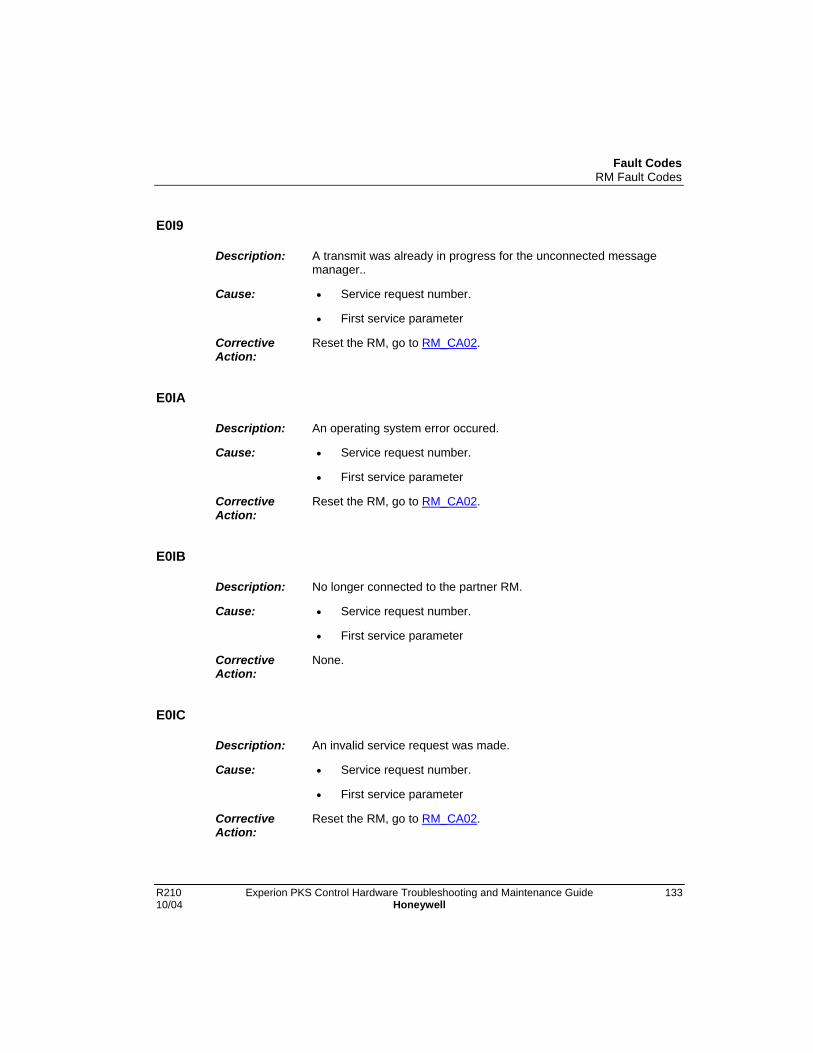
Fault CodesRM Fault Codes
R210 Experion PKS Control Hardware Troubleshooting and Maintenance Guide 13310/04 Honeywell
E0I9
Description: A transmit was already in progress for the unconnected messagemanager..
Cause: • Service request number.
• First service parameter
CorrectiveAction:
Reset the RM, go to RM_CA02.
E0IA
Description: An operating system error occured.
Cause: • Service request number.
• First service parameter
CorrectiveAction:
Reset the RM, go to RM_CA02.
E0IB
Description: No longer connected to the partner RM.
Cause: • Service request number.
• First service parameter
CorrectiveAction:
None.
E0IC
Description: An invalid service request was made.
Cause: • Service request number.
• First service parameter
CorrectiveAction:
Reset the RM, go to RM_CA02.
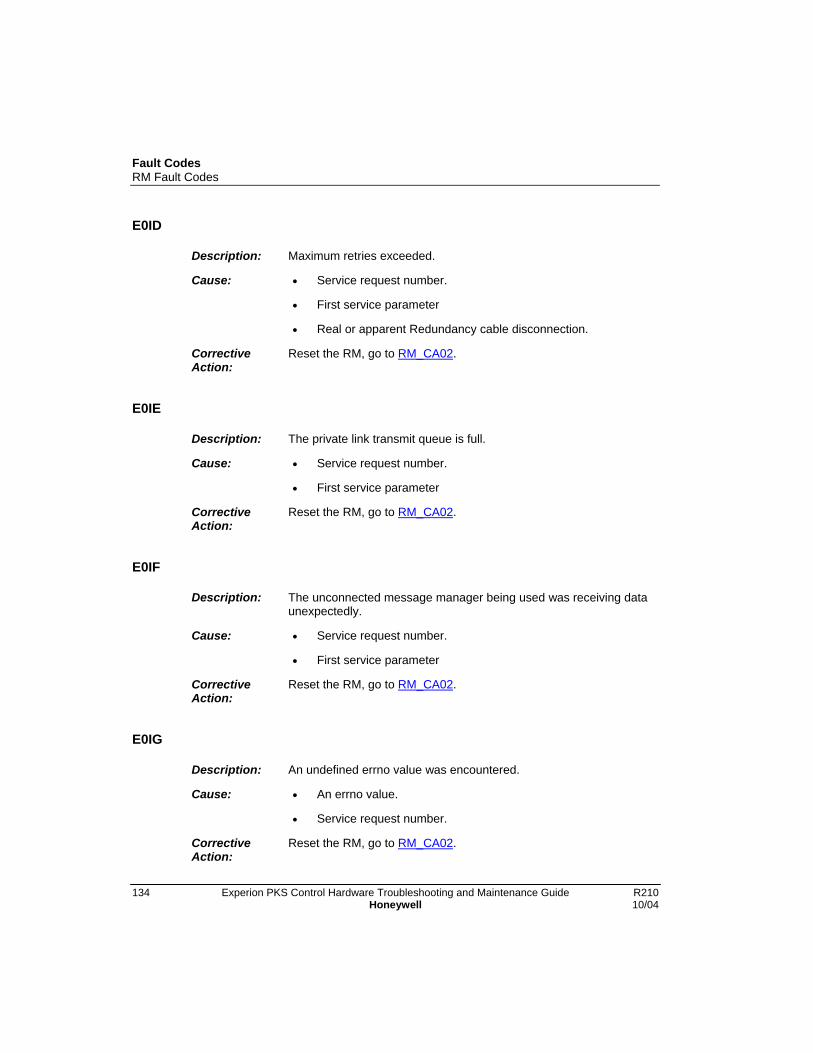
Fault CodesRM Fault Codes
134 Experion PKS Control Hardware Troubleshooting and Maintenance Guide R210Honeywell 10/04
E0ID
Description: Maximum retries exceeded.
Cause: • Service request number.
• First service parameter
• Real or apparent Redundancy cable disconnection.
CorrectiveAction:
Reset the RM, go to RM_CA02.
E0IE
Description: The private link transmit queue is full.
Cause: • Service request number.
• First service parameter
CorrectiveAction:
Reset the RM, go to RM_CA02.
E0IF
Description: The unconnected message manager being used was receiving dataunexpectedly.
Cause: • Service request number.
• First service parameter
CorrectiveAction:
Reset the RM, go to RM_CA02.
E0IG
Description: An undefined errno value was encountered.
Cause: • An errno value.
• Service request number.
CorrectiveAction:
Reset the RM, go to RM_CA02.

Fault CodesRM Fault Codes
R210 Experion PKS Control Hardware Troubleshooting and Maintenance Guide 13510/04 Honeywell
E0J0
Description: Error taking a semaphore for access to data structures forforwarding report events services to the partner RM.
Cause: • An errno value.
• Service request number.
CorrectiveAction:
Reset the RM, go to RM_CA02.
E101
Description: Unable to initialize indicator device driver.
Cause: An errno value returned from indDrv.
CorrectiveAction:
Reset the RM, go to RM_CA02.
E102
Description: Unable to create “/display” device (4 character display).
Cause: An errno value returned from indDevCreate.
CorrectiveAction:
Reset the RM, go to RM_CA02.
E103
Description: Unable to create “/commLed” device.
Cause: An errno value returned from indDevCreate.
CorrectiveAction:
Reset the RM, go to RM_CA02.

Fault CodesRM Fault Codes
136 Experion PKS Control Hardware Troubleshooting and Maintenance Guide R210Honeywell 10/04
E104
Description: Unable to create “/healthLed” device.
Cause: An errno value returned from indDevCreate.
CorrectiveAction:
Reset the RM, go to RM_CA02.
E105
Description: Unable to create “/priLed” device.
Cause: An errno value returned from indDevCreate.
CorrectiveAction:
Reset the RM, go to RM_CA02.
E106
Description: Unable to create “/secLed” device.
Cause: An errno value returned from indDevCreate.
CorrectiveAction:
Reset the RM, go to RM_CA02.
E107
Description: Unable to create “/relay” device.
Cause: An errno value returned from indDevCreate.
CorrectiveAction:
Reset the RM, go to RM_CA02.
E108
Description: Unable to initialize event log object.
Cause: An errno value returned from eloInit.
CorrectiveAction:
Reset the RM, go to RM_CA02.
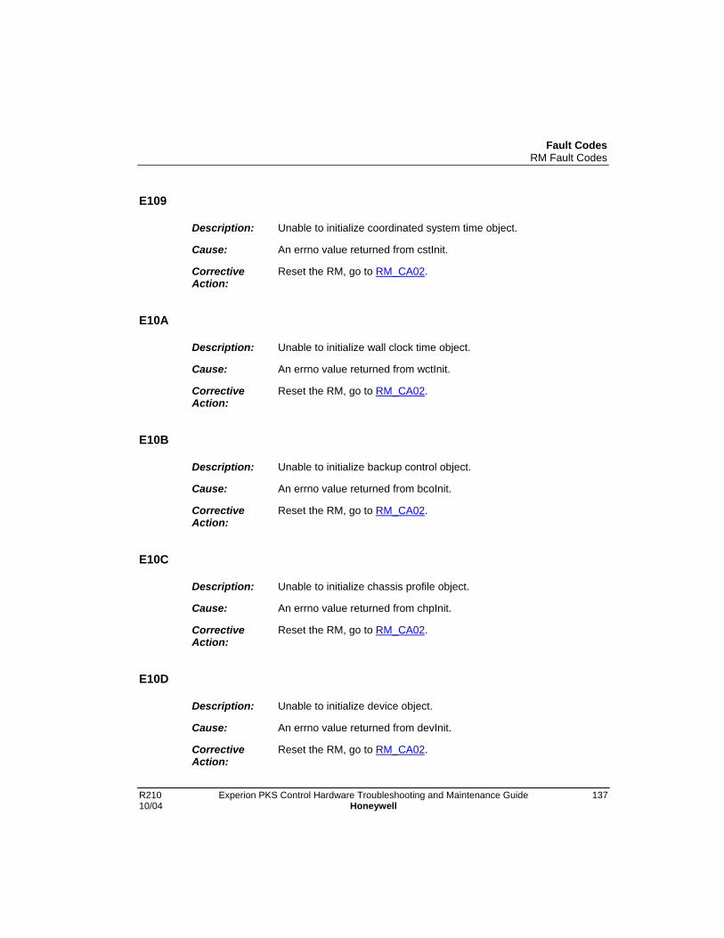
Fault CodesRM Fault Codes
R210 Experion PKS Control Hardware Troubleshooting and Maintenance Guide 13710/04 Honeywell
E109
Description: Unable to initialize coordinated system time object.
Cause: An errno value returned from cstInit.
CorrectiveAction:
Reset the RM, go to RM_CA02.
E10A
Description: Unable to initialize wall clock time object.
Cause: An errno value returned from wctInit.
CorrectiveAction:
Reset the RM, go to RM_CA02.
E10B
Description: Unable to initialize backup control object.
Cause: An errno value returned from bcoInit.
CorrectiveAction:
Reset the RM, go to RM_CA02.
E10C
Description: Unable to initialize chassis profile object.
Cause: An errno value returned from chpInit.
CorrectiveAction:
Reset the RM, go to RM_CA02.
E10D
Description: Unable to initialize device object.
Cause: An errno value returned from devInit.
CorrectiveAction:
Reset the RM, go to RM_CA02.
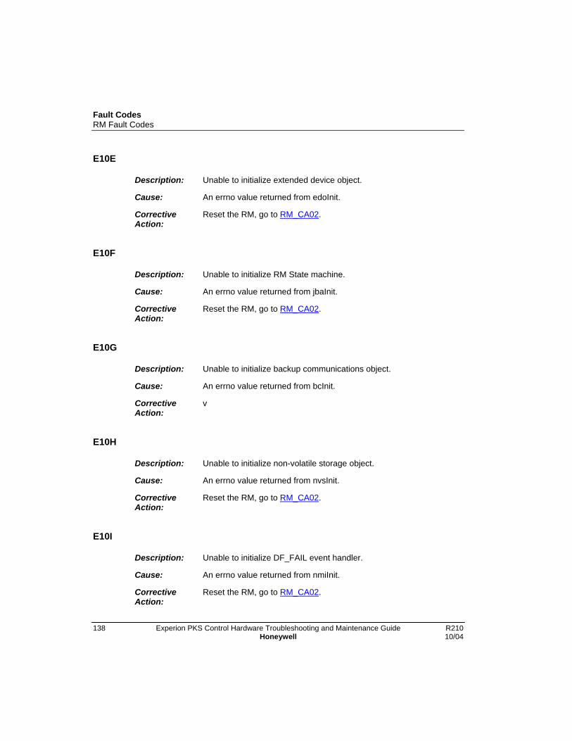
Fault CodesRM Fault Codes
138 Experion PKS Control Hardware Troubleshooting and Maintenance Guide R210Honeywell 10/04
E10E
Description: Unable to initialize extended device object.
Cause: An errno value returned from edoInit.
CorrectiveAction:
Reset the RM, go to RM_CA02.
E10F
Description: Unable to initialize RM State machine.
Cause: An errno value returned from jbaInit.
CorrectiveAction:
Reset the RM, go to RM_CA02.
E10G
Description: Unable to initialize backup communications object.
Cause: An errno value returned from bcInit.
CorrectiveAction:
v
E10H
Description: Unable to initialize non-volatile storage object.
Cause: An errno value returned from nvsInit.
CorrectiveAction:
Reset the RM, go to RM_CA02.
E10I
Description: Unable to initialize DF_FAIL event handler.
Cause: An errno value returned from nmiInit.
CorrectiveAction:
Reset the RM, go to RM_CA02.

Fault CodesRM Fault Codes
R210 Experion PKS Control Hardware Troubleshooting and Maintenance Guide 13910/04 Honeywell
E10J
Description: Unable to initialize workstation display object.
Cause: An errno value returned from wdoInit.
CorrectiveAction:
Reset the RM, go to RM_CA02.
E10K
Description: Unable to initialize self test object.
Cause: An errno value returned from stoInit.
CorrectiveAction:
Reset the RM, go to RM_CA02.
E10L
Description: Unable to initialize watchdog manager.
Cause: An errno value returned from dogInit.
CorrectiveAction:
Reset the RM, go to RM_CA02.
E10M
Description: Unable to initialize display task.
Cause: Unable to initialize display task.
CorrectiveAction:
Reset the RM, go to RM_CA02.
E10N
Description: Unable to initialize ICP object.
Cause: An errno value returned from icpObjInit.
CorrectiveAction:
Reset the RM, go to RM_CA02.

Fault CodesRM Fault Codes
140 Experion PKS Control Hardware Troubleshooting and Maintenance Guide R210Honeywell 10/04
E10P
Description: Unable to post event to device object for displaying ‘BOOT’ whenrunning in boot mode.
Cause: An errno value returned from devEventPost.
CorrectiveAction:
Reset the RM, go to RM_CA02.
E201
Description: Error collecting redundancy attribute data from all existing modules.
Cause:
CorrectiveAction:
Reset the RM, go to RM_CA02.
E202
Description: Error collected device attribute data from all existing modules.
Cause:
CorrectiveAction:
None.
E203
Description: Error collecting redundancy attribute data from all existing modules.
Cause:
CorrectiveAction:
None.
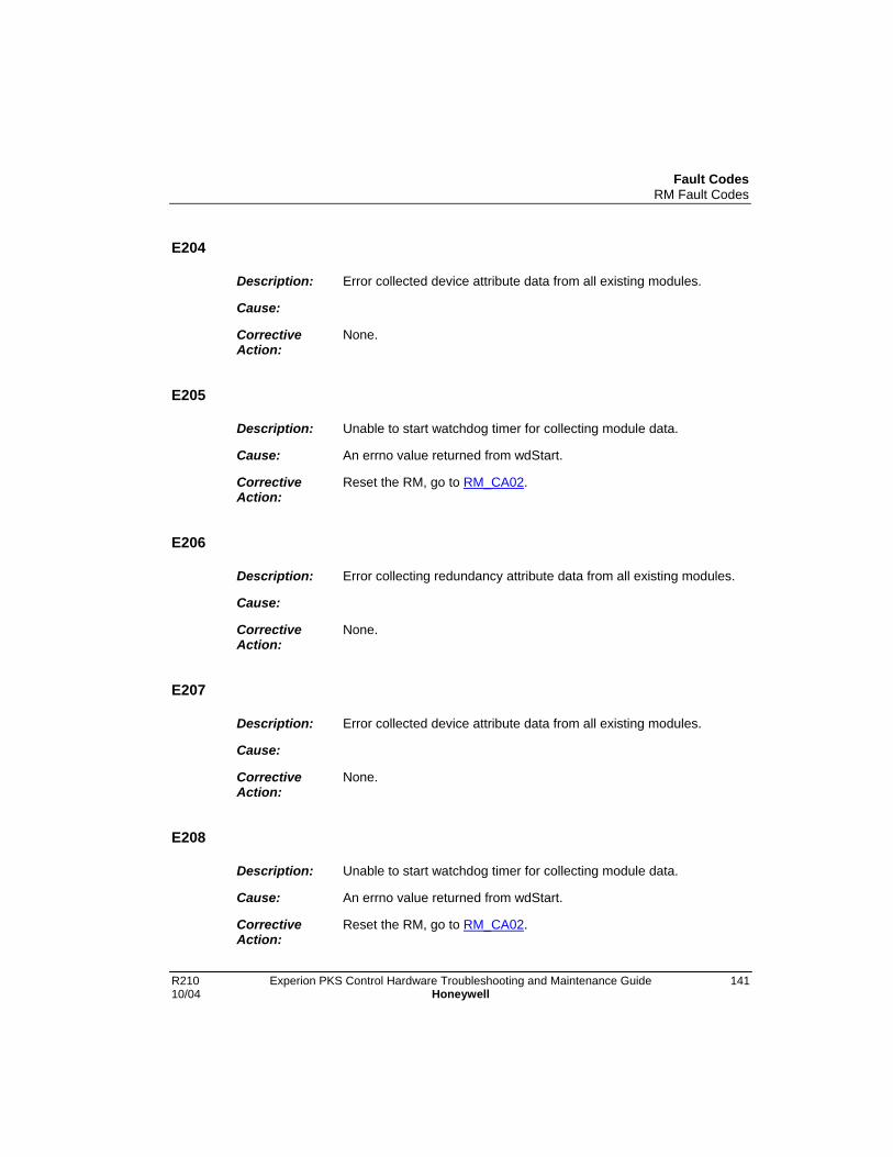
Fault CodesRM Fault Codes
R210 Experion PKS Control Hardware Troubleshooting and Maintenance Guide 14110/04 Honeywell
E204
Description: Error collected device attribute data from all existing modules.
Cause:
CorrectiveAction:
None.
E205
Description: Unable to start watchdog timer for collecting module data.
Cause: An errno value returned from wdStart.
CorrectiveAction:
Reset the RM, go to RM_CA02.
E206
Description: Error collecting redundancy attribute data from all existing modules.
Cause:
CorrectiveAction:
None.
E207
Description: Error collected device attribute data from all existing modules.
Cause:
CorrectiveAction:
None.
E208
Description: Unable to start watchdog timer for collecting module data.
Cause: An errno value returned from wdStart.
CorrectiveAction:
Reset the RM, go to RM_CA02.

Fault CodesRM Fault Codes
142 Experion PKS Control Hardware Troubleshooting and Maintenance Guide R210Honeywell 10/04
E209
Description: Received a startup time value from a module which is greater than 3minutes.
Cause: • Startup time value received
• Slot number from which the value was received
CorrectiveAction:
Reset the RM, go to RM_CA02.
E20A
Description: Unable to update the chassis ID in all redundancy compliantmodules.
Cause:
CorrectiveAction:
None.
E20B
Description: Unable to send partner present attribute to a specific module.
Cause: Slot number of module.
CorrectiveAction:
None.
E20C
Description: Unable to get partner redundancy map when checking for a partnermodule.
Cause: Slot number of module for which a partner is being checked.
CorrectiveAction:
None.
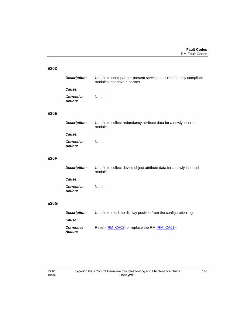
Fault CodesRM Fault Codes
R210 Experion PKS Control Hardware Troubleshooting and Maintenance Guide 14310/04 Honeywell
E20D
Description: Unable to send partner present service to all redundancy compliantmodules that have a partner.
Cause:
CorrectiveAction:
None.
E20E
Description: Unable to collect redundancy attribute data for a newly insertedmodule.
Cause:
CorrectiveAction:
None.
E20F
Description: Unable to collect device object attribute data for a newly insertedmodule.
Cause:
CorrectiveAction:
None.
E20G
Description: Unable to read the display position from the configuration log.
Cause:
CorrectiveAction:
Reset ( RM_CA02) or replace the RM (RM_CA01).
Fault CodesRM Fault Codes
144 Experion PKS Control Hardware Troubleshooting and Maintenance Guide R210Honeywell 10/04
E20H
Description: Unable to notify newly inserted module of current chassis ID.
Cause:
CorrectiveAction:
None.
E20I
Description: Unable to start watchdog timer to monitor for SYS_FAIL_Ldeassertion.
Cause: An errno value returned from wdStart
CorrectiveAction:
Reset the RM, go to RM_CA02.
E20J
Description: Unable to update the chassis ID in all redundancy compliantmodules.
Cause:
CorrectiveAction:
None.
E20K
Description: Invalid event sent to the chassis profile object.
Cause: Invalid event number.
CorrectiveAction:
Reset the RM, go to RM_CA02.
Fault CodesRM Fault Codes
R210 Experion PKS Control Hardware Troubleshooting and Maintenance Guide 14510/04 Honeywell
E20L
Description: Error reading message from message queue.
Cause: An errno value returned from msgQReceive.
CorrectiveAction:
Reset the RM, go to RM_CA02.
E20M
Description: Error in stop service processing.
Cause: • Stop service resulting state.
• The slot number where stop service processing stopped.
CorrectiveAction:
Non-redundant modules at the slot number or past the slot numbermay have not been stopped.
E210
Description: Unable to allocate a response combuf.
Cause:
CorrectiveAction:
None.
E211
Description: Response routine pointer is NULL.
Cause:
CorrectiveAction:
Reset the RM, go to RM_CA02.

Fault CodesRM Fault Codes
146 Experion PKS Control Hardware Troubleshooting and Maintenance Guide R210Honeywell 10/04
E230
Description: Unable to close an unconnected message manager resource.
Cause: • Service request.
• First service request parameter.
CorrectiveAction:
Reset the RM, go to RM_CA02.
E235
Description: Unable to close an unconnected message manager resource.
Cause: • Service request.
• First service request parameter.
CorrectiveAction:
Reset the RM, go to RM_CA02.
E236
Description: Unable to close an unconnected message manager resource.
Cause: • Service request.
• First service request parameter.
CorrectiveAction:
Reset the RM, go to RM_CA02.
E237
Description: Unable to close an unconnected message manager resource.
Cause: • Service request.
• First service request parameter.
CorrectiveAction:
Reset the RM, go to RM_CA02.
Fault CodesRM Fault Codes
R210 Experion PKS Control Hardware Troubleshooting and Maintenance Guide 14710/04 Honeywell
E239
Description: Unable to close an unconnected message manager resource.
Cause: • Service request.
• First service request parameter.
CorrectiveAction:
Reset the RM, go to RM_CA02.
E23B
Description: Unable to close an unconnected message manager resource.
Cause: • Service request.
• First service request parameter.
CorrectiveAction:
Reset the RM, go to RM_CA02.
E250
Description: Unable to allocate combuf
Cause: • Service request.
• First service request parameter.
CorrectiveAction:
None.
E251
Description: Unable to allocate unconnected message manager resource.
Cause:
CorrectiveAction:
None.

Fault CodesRM Fault Codes
148 Experion PKS Control Hardware Troubleshooting and Maintenance Guide R210Honeywell 10/04
E252
Description: Unable to send unconnected request.
Cause:
CorrectiveAction:
None.
E253
Description: Unable to close unconnected message manager resource.
Cause:
CorrectiveAction:
Reset the RM, go to RM_CA02.
E254
Description: Unable to close unconnected message manager resource.
Cause:
CorrectiveAction:
Reset the RM, go to RM_CA02.
E255
Description: Unable to close unconnected message manager resource.
Cause:
CorrectiveAction:
Reset the RM, go to RM_CA02.
E256
Description: Unable to close unconnected message manager resource.
Cause:
CorrectiveAction:
Reset the RM, go to RM_CA02.

Fault CodesRM Fault Codes
R210 Experion PKS Control Hardware Troubleshooting and Maintenance Guide 14910/04 Honeywell
E257
Description: Unable to close unconnected message manager resource.
Cause:
CorrectiveAction:
Reset the RM, go to RM_CA02.
E258
Description: Unable to close unconnected message manager resource.
Cause:
CorrectiveAction:
Reset the RM, go to RM_CA02.
E259
Description: Unable to close unconnected message manager resource.
Cause:
CorrectiveAction:
Reset the RM, go to RM_CA02.
E25A
Description: Unable to allocate combuf.
Cause:
CorrectiveAction:
None.
E25B
Description: Unable to allocate unconnected message manager resource.
Cause:
CorrectiveAction:
None.

Fault CodesRM Fault Codes
150 Experion PKS Control Hardware Troubleshooting and Maintenance Guide R210Honeywell 10/04
E25C
Description: Unable to send unconnected request.
Cause:
CorrectiveAction:
None.
E25D
Description: Unable to close unconnected message manager resource.
Cause:
CorrectiveAction:
Reset the RM, go to RM_CA02.
E25E
Description: Unable to close unconnected message manager resource.
Cause:
CorrectiveAction:
Reset the RM, go to RM_CA02.
E25F
Description: Unable to close unconnected message manager resource.
Cause:
CorrectiveAction:
Reset the RM, go to RM_CA02.
E25G
Description: Unable to close unconnected message manager resource.
Cause:
CorrectiveAction:
Reset the RM, go to RM_CA02.

Fault CodesRM Fault Codes
R210 Experion PKS Control Hardware Troubleshooting and Maintenance Guide 15110/04 Honeywell
E25H
Description: Unable to close unconnected message manager resource.
Cause:
CorrectiveAction:
Reset the RM, go to RM_CA02.
E25I
Description: Unable to close unconnected message manager resource.
Cause:
CorrectiveAction:
Reset the RM, go to RM_CA02.
E25J
Description: Unable to close unconnected message manager resource.
Cause:
CorrectiveAction:
Reset the RM, go to RM_CA02.
E260
Description: Unable to allocate combuf.
Cause: Destination slot number.
CorrectiveAction:
None.

Fault CodesRM Fault Codes
152 Experion PKS Control Hardware Troubleshooting and Maintenance Guide R210Honeywell 10/04
E261
Description: Unable to allocate unconnected message manager resource.
Cause: • UCMM Handle.
• Destination slot number.
CorrectiveAction:
None.
E262
Description: Unable to send unconnected request.
Cause: • UCMM Handle.
• Destination slot number.
CorrectiveAction:
None.
E263
Description: Unable to close unconnected message manager resource.
Cause:
CorrectiveAction:
Reset the RM, go to RM_CA02.
E264
Description: Unable to close unconnected message manager resource.
Cause: • UCMM Handle.
• Destination slot number.
CorrectiveAction:
Reset the RM, go to RM_CA02.

Fault CodesRM Fault Codes
R210 Experion PKS Control Hardware Troubleshooting and Maintenance Guide 15310/04 Honeywell
E265
Description: Unable to close unconnected message manager resource.
Cause: • UCMM Handle.
• Destination slot number.
CorrectiveAction:
Reset the RM, go to RM_CA02.
E266
Description: Retries exceeded trying to do primary capability check with module.
Cause: Destination slot number.
CorrectiveAction:
None.
E267
Description: Unable to close unconnected message manager resource.
Cause: • UCMM Handle.
• Destination slot number.
CorrectiveAction:
Reset the RM, go to RM_CA02.
E268
Description: Unable to close unconnected message manager resource.
Cause: • UCMM Handle.
• Destination slot number.
CorrectiveAction:
Reset the RM, go to RM_CA02.
Fault CodesRM Fault Codes
154 Experion PKS Control Hardware Troubleshooting and Maintenance Guide R210Honeywell 10/04
E269
Description: Unable to close unconnected message manager resource.
Cause: • UCMM Handle.
• Destination slot number.
CorrectiveAction:
Reset the RM, go to RM_CA02.
E26A
Description: Invalid internal state reached.
Cause: • Invalid state number.
• Destination slot number.
CorrectiveAction:
Reset the RM, go to RM_CA02.
E26B
Description: Unable to close unconnected message manager resource.
Cause: • UCMM Handle.
• Destination slot number.
CorrectiveAction:
Reset the RM, go to RM_CA02.
E270
Description: Unable to collect redundancy attribute data.
Cause:
CorrectiveAction:
Reset the RM, go to RM_CA02.

Fault CodesRM Fault Codes
R210 Experion PKS Control Hardware Troubleshooting and Maintenance Guide 15510/04 Honeywell
E271
Description: Unable to collect device object attribute data.
Cause:
CorrectiveAction:
None
E280
Description: Unable to allocate combuf.
Cause:
CorrectiveAction:
None
E281
Description: Unable to allocate unconnected message manager resource.
Cause: • UCMM Handle.
• Destination slot number.
CorrectiveAction:
None
E282
Description: Unable to send unconnected request.
Cause: • UCMM Handle.
• Destination slot number.
CorrectiveAction:
None
Fault CodesRM Fault Codes
156 Experion PKS Control Hardware Troubleshooting and Maintenance Guide R210Honeywell 10/04
E283
Description: Unable to close unconnected message manager resource.
Cause: • UCMM Handle.
• Destination slot number.
CorrectiveAction:
Reset the RM, go to RM_CA02.
E284
Description: Unable to close unconnected message manager resource.
Cause: • UCMM Handle.
• Destination slot number.
CorrectiveAction:
Reset the RM, go to RM_CA02.
E285
Description: Unable to close unconnected message manager resource.
Cause: • UCMM Handle.
• Destination slot number.
CorrectiveAction:
Reset the RM, go to RM_CA02.
E288
Description: Unable to close unconnected message manager resource.
Cause: • UCMM Handle.
• Destination slot number.
CorrectiveAction:
Reset the RM, go to RM_CA02.
Fault CodesRM Fault Codes
R210 Experion PKS Control Hardware Troubleshooting and Maintenance Guide 15710/04 Honeywell
E289
Description: Unable to close unconnected message manager resource.
Cause: • UCMM Handle.
• Destination slot number.
CorrectiveAction:
Reset the RM, go to RM_CA02.
E28A
Description: Unable to close unconnected message manager resource.
Cause: • UCMM Handle.
• Destination slot number.
CorrectiveAction:
Reset the RM, go to RM_CA02.
E28B
Description: Retry to a module not communicating.
Cause: Destination slot number.
CorrectiveAction:
None.
E28C
Description: Unable to close unconnected message manager resource.
Cause: • UCMM Handle.
• Destination slot number.
CorrectiveAction:
Reset the RM, go to RM_CA02.
Fault CodesRM Fault Codes
158 Experion PKS Control Hardware Troubleshooting and Maintenance Guide R210Honeywell 10/04
E28D
Description: Bad stop service state number.
Cause: • Stop service state number.
• Destination slot number.
CorrectiveAction:
Reset the RM, go to RM_CA02.
E290
Description: Unable to allocate combuf.
Cause: Destination slot number.
CorrectiveAction:
None.
E291
Description: Unable to allocate unconnected message manager resource.
Cause: • UCMM Handle.
• Destination slot number.
CorrectiveAction:
None
E292
Description: Unable to send unconnected request.
Cause: • UCMM Handle.
• Destination slot number.
CorrectiveAction:
None

Fault CodesRM Fault Codes
R210 Experion PKS Control Hardware Troubleshooting and Maintenance Guide 15910/04 Honeywell
E293
Description: Unable to close unconnected message manager resource.
Cause: • UCMM Handle.
• Destination slot number.
CorrectiveAction:
Reset the RM, go to RM_CA02.
E294
Description: Unable to close unconnected message manager resource.
Cause: • UCMM Handle.
• Destination slot number.
CorrectiveAction:
Reset the RM, go to RM_CA02.
E295
Description: Unable to close unconnected message manager resource.
Cause: • UCMM Handle.
• Destination slot number.
CorrectiveAction:
Reset the RM, go to RM_CA02.
E296
Description: Retries exceeded trying to send partner present service to module.
Cause: Destination slot number.
CorrectiveAction:
None.

Fault CodesRM Fault Codes
160 Experion PKS Control Hardware Troubleshooting and Maintenance Guide R210Honeywell 10/04
E297
Description: Unable to close unconnected message manager resource.
Cause: • UCMM Handle.
• Destination slot number.
CorrectiveAction:
Reset the RM, go to RM_CA02.
E298
Description: Unable to send partner present service to module.
Cause: • Partner present state number.
• Destination slot number.
CorrectiveAction:
Reset the RM, go to RM_CA02.
E299
Description: Unable to close unconnected message manager resource.
Cause: • UCMM Handle.
• Destination slot number.
CorrectiveAction:
Reset the RM, go to RM_CA02.
E2B0
Description: Unable to allocate combuf.
Cause:
CorrectiveAction:
Reset the RM, go to RM_CA02.
Fault CodesRM Fault Codes
R210 Experion PKS Control Hardware Troubleshooting and Maintenance Guide 16110/04 Honeywell
E2B1
Description: Not connected to partner RM.
Cause:
CorrectiveAction:
None.
E2B2
Description: Resources not available for partner unconnected request.
Cause: An errno value returned from bcUcmmOpen.
CorrectiveAction:
Reset the RM, go to RM_CA02.
E2B3
Description: Combuf not available for unconnected response.
Cause:
CorrectiveAction:
Reset the RM, go to RM_CA02.
E2B4
Description: Unknown errno value returned from bcUcmmOpen.
Cause: An errno value returned from bcUcmmOpen.
CorrectiveAction:
Reset the RM, go to RM_CA02.
E2B5
Description: A bad handle was used for partner unconnected request.
Cause:
CorrectiveAction:
Reset the RM, go to RM_CA02.

Fault CodesRM Fault Codes
162 Experion PKS Control Hardware Troubleshooting and Maintenance Guide R210Honeywell 10/04
E2B6
Description: Not connected to partner RM.
Cause:
CorrectiveAction:
None.
E2B7
Description: An unconnected request for the unconnected resource is already inprogress.
Cause:
CorrectiveAction:
Reset the RM, go to RM_CA02.
E2B8
Description: An operating resource error occurred while trying to send unconnectrequest.
Cause:
CorrectiveAction:
Reset the RM, go to RM_CA02.
E2B9
Description: The transmit queue is full for private link communications.
Cause:
CorrectiveAction:
Reset the RM, go to RM_CA02.
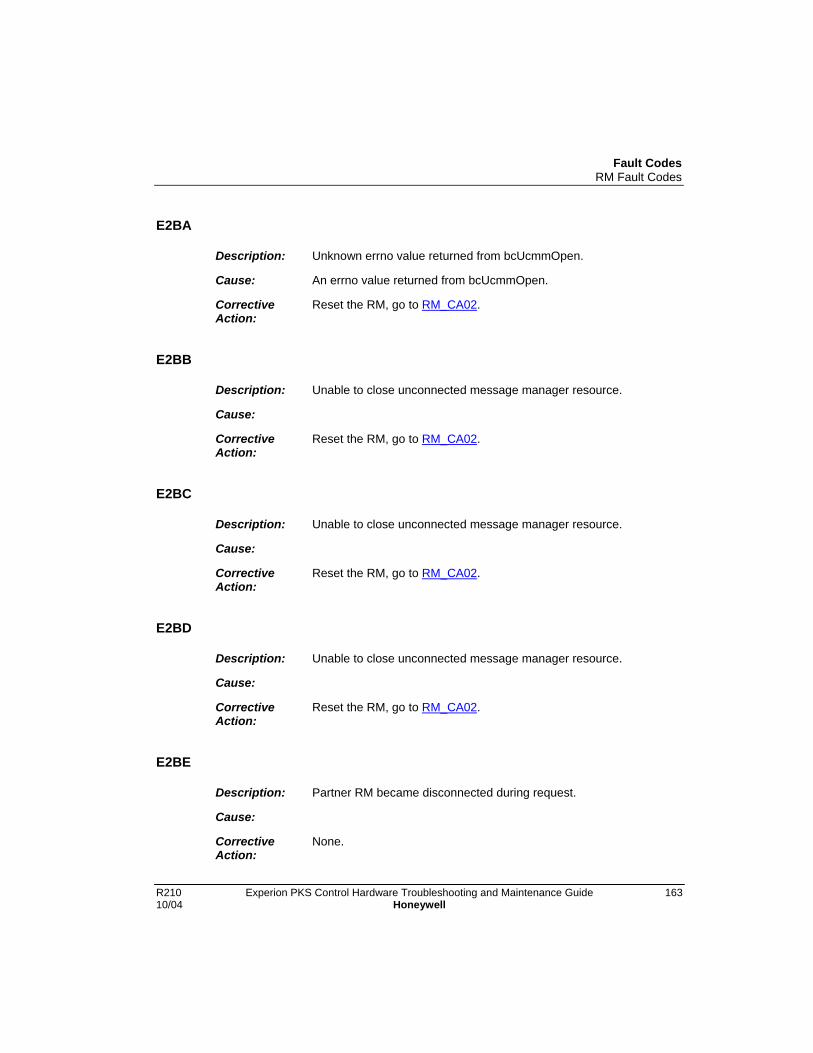
Fault CodesRM Fault Codes
R210 Experion PKS Control Hardware Troubleshooting and Maintenance Guide 16310/04 Honeywell
E2BA
Description: Unknown errno value returned from bcUcmmOpen.
Cause: An errno value returned from bcUcmmOpen.
CorrectiveAction:
Reset the RM, go to RM_CA02.
E2BB
Description: Unable to close unconnected message manager resource.
Cause:
CorrectiveAction:
Reset the RM, go to RM_CA02.
E2BC
Description: Unable to close unconnected message manager resource.
Cause:
CorrectiveAction:
Reset the RM, go to RM_CA02.
E2BD
Description: Unable to close unconnected message manager resource.
Cause:
CorrectiveAction:
Reset the RM, go to RM_CA02.
E2BE
Description: Partner RM became disconnected during request.
Cause:
CorrectiveAction:
None.
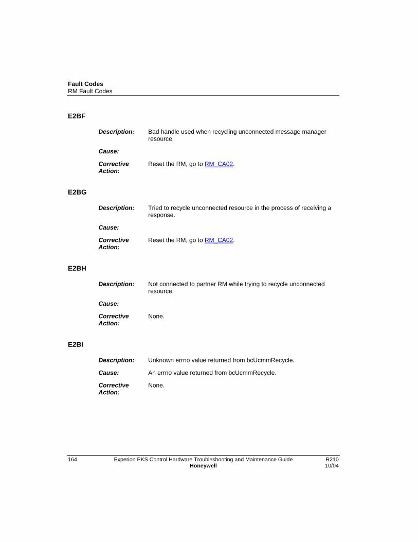
Fault CodesRM Fault Codes
164 Experion PKS Control Hardware Troubleshooting and Maintenance Guide R210Honeywell 10/04
E2BF
Description: Bad handle used when recycling unconnected message managerresource.
Cause:
CorrectiveAction:
Reset the RM, go to RM_CA02.
E2BG
Description: Tried to recycle unconnected resource in the process of receiving aresponse.
Cause:
CorrectiveAction:
Reset the RM, go to RM_CA02.
E2BH
Description: Not connected to partner RM while trying to recycle unconnectedresource.
Cause:
CorrectiveAction:
None.
E2BI
Description: Unknown errno value returned from bcUcmmRecycle.
Cause: An errno value returned from bcUcmmRecycle.
CorrectiveAction:
None.

Fault CodesRM Fault Codes
R210 Experion PKS Control Hardware Troubleshooting and Maintenance Guide 16510/04 Honeywell
E2BJ
Description: Unable to close unconnected message manager resource.
Cause: Handle of unconnected message manager resource.
CorrectiveAction:
Reset the RM, go to RM_CA02.
E2BK
Description: Invalid internal state reached.
Cause: Invalid state value.
CorrectiveAction:
Reset the RM, go to RM_CA02.
E2BL
Description: Unable to close unconnected message manager resource.
Cause:
CorrectiveAction:
Reset the RM, go to RM_CA02.
E2C0
Description: Unable to allocate combuf.
Cause:
CorrectiveAction:
Reset the RM, go to RM_CA02.
E2C1
Description: Not connected to partner RM.
Cause:
CorrectiveAction:
None.
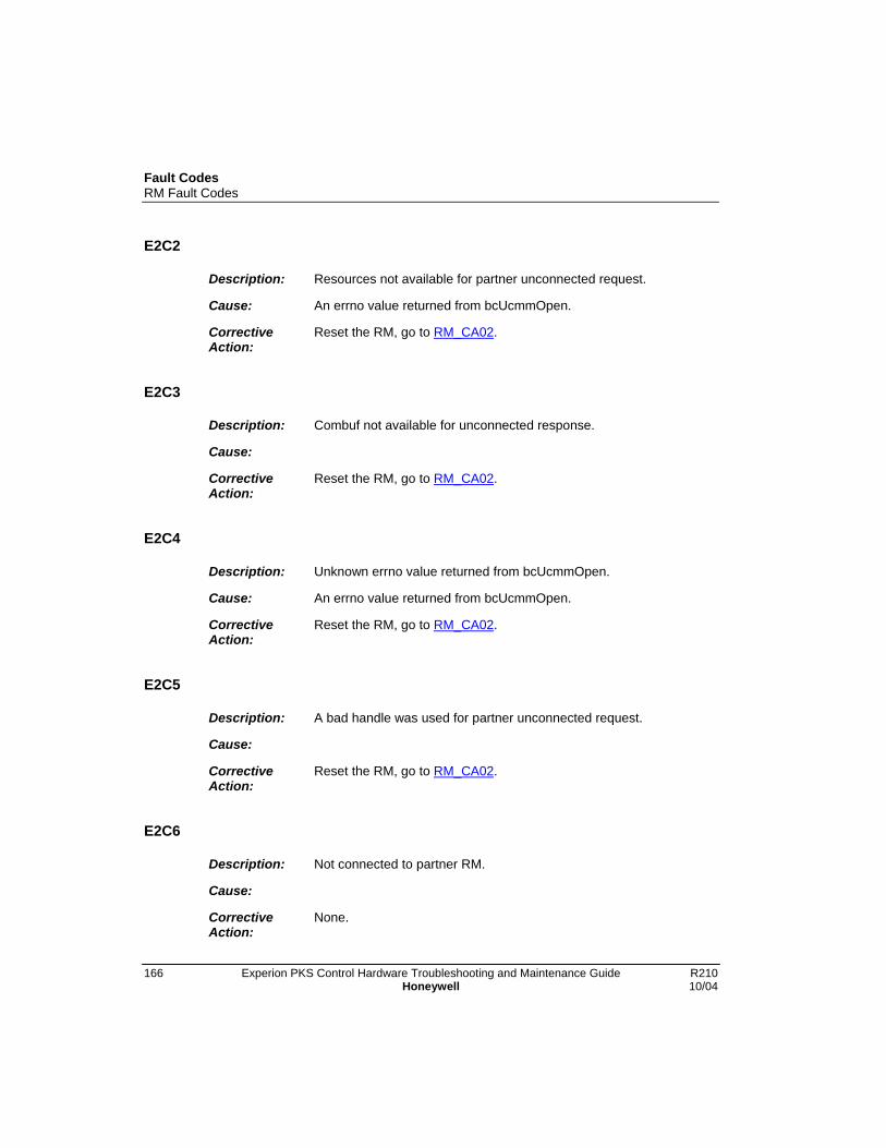
Fault CodesRM Fault Codes
166 Experion PKS Control Hardware Troubleshooting and Maintenance Guide R210Honeywell 10/04
E2C2
Description: Resources not available for partner unconnected request.
Cause: An errno value returned from bcUcmmOpen.
CorrectiveAction:
Reset the RM, go to RM_CA02.
E2C3
Description: Combuf not available for unconnected response.
Cause:
CorrectiveAction:
Reset the RM, go to RM_CA02.
E2C4
Description: Unknown errno value returned from bcUcmmOpen.
Cause: An errno value returned from bcUcmmOpen.
CorrectiveAction:
Reset the RM, go to RM_CA02.
E2C5
Description: A bad handle was used for partner unconnected request.
Cause:
CorrectiveAction:
Reset the RM, go to RM_CA02.
E2C6
Description: Not connected to partner RM.
Cause:
CorrectiveAction:
None.

Fault CodesRM Fault Codes
R210 Experion PKS Control Hardware Troubleshooting and Maintenance Guide 16710/04 Honeywell
E2C7
Description: An unconnected request for the unconnected resource is already inprogress.
Cause:
CorrectiveAction:
Reset the RM, go to RM_CA02.
E2C8
Description: An operating resource error occurred while trying to send unconnectrequest.
Cause:
CorrectiveAction:
Reset the RM, go to RM_CA02.
E2C9
Description: The transmit queue is full for private link communications.
Cause:
CorrectiveAction:
Reset the RM, go to RM_CA02.
E2CA
Description: Unknown errno value returned from bcUcmmOpen.
Cause: An errno value returned from bcUcmmOpen.
CorrectiveAction:
Reset the RM, go to RM_CA02.

Fault CodesRM Fault Codes
168 Experion PKS Control Hardware Troubleshooting and Maintenance Guide R210Honeywell 10/04
E2CB
Description: Unable to close unconnected message manager resource.
Cause:
CorrectiveAction:
Reset the RM, go to RM_CA02.
E2CC
Description: Unable to close unconnected message manager resource.
Cause:
CorrectiveAction:
Reset the RM, go to RM_CA02.
E2CD
Description: Unable to close unconnected message manager resource.
Cause:
CorrectiveAction:
Reset the RM, go to RM_CA02.
E2CE
Description: Partner RM became disconnected during request.
Cause:
CorrectiveAction:
None.

Fault CodesRM Fault Codes
R210 Experion PKS Control Hardware Troubleshooting and Maintenance Guide 16910/04 Honeywell
E2CF
Description: Bad handle used when recycling unconnected message managerresource.
Cause:
CorrectiveAction:
Reset the RM, go to RM_CA02.
E2CG
Description: Tried to recycle unconnected resource in the process of receiving aresponse.
Cause:
CorrectiveAction:
Reset the RM, go to RM_CA02.
E2CH
Description: Not connected to partner RM while trying to recycle unconnectedresource.
Cause:
CorrectiveAction:
None.
E2CI
Description: Unknown errno value returned from bcUcmmRecycle.
Cause: An errno value returned from bcUcmmRecycle.
CorrectiveAction:
None.

Fault CodesRM Fault Codes
170 Experion PKS Control Hardware Troubleshooting and Maintenance Guide R210Honeywell 10/04
E2CJ
Description: Unable to close unconnected message manager resource.
Cause: Handle of unconnected message manager resource.
CorrectiveAction:
Reset the RM, go to RM_CA02.
E2CK
Description: Invalid internal state reached.
Cause: Invalid state value.
CorrectiveAction:
Reset the RM, go to RM_CA02.
E2CL
Description: Unable to close unconnected message manager resource.
Cause:
CorrectiveAction:
Reset the RM, go to RM_CA02.
E2D0
Description: Unable to start watchdog timer for monitoring.
Cause: An errno value returned from wdStart.
CorrectiveAction:
Reset the RM, go to RM_CA02.
E2E0
Description: Unable to allocate combuf.
Cause: Slot number of module to be queried.
CorrectiveAction:
None.

Fault CodesRM Fault Codes
R210 Experion PKS Control Hardware Troubleshooting and Maintenance Guide 17110/04 Honeywell
E2E1
Description: Unable to allocate unconnected message manager resource.
Cause: Slot number of module to be queried.
CorrectiveAction:
None.
E2E2
Description: Unable to take semaphore for collecting redundancy attributes.
Cause: An errno value returned from semTake.
CorrectiveAction:
Reset the RM, go to RM_CA02.
E2E3
Description: Unable to close unconnected message manager resource.
Cause: • Slot number of module to be queried.
• UCMM Handle.
CorrectiveAction:
Reset the RM, go to RM_CA02.
E2E4
Description: Unable to take semphore used to verify a switchover is not inprogress.
Cause:
CorrectiveAction:
Reset the RM, go to RM_CA02.
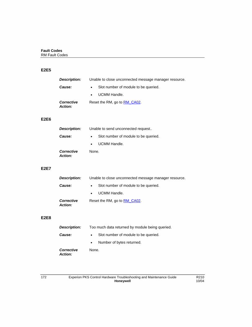
Fault CodesRM Fault Codes
172 Experion PKS Control Hardware Troubleshooting and Maintenance Guide R210Honeywell 10/04
E2E5
Description: Unable to close unconnected message manager resource.
Cause: • Slot number of module to be queried.
• UCMM Handle.
CorrectiveAction:
Reset the RM, go to RM_CA02.
E2E6
Description: Unable to send unconnected request..
Cause: • Slot number of module to be queried.
• UCMM Handle.
CorrectiveAction:
None.
E2E7
Description: Unable to close unconnected message manager resource.
Cause: • Slot number of module to be queried.
• UCMM Handle.
CorrectiveAction:
Reset the RM, go to RM_CA02.
E2E8
Description: Too much data returned by module being queried.
Cause: • Slot number of module to be queried.
• Number of bytes returned.
CorrectiveAction:
None.

Fault CodesRM Fault Codes
R210 Experion PKS Control Hardware Troubleshooting and Maintenance Guide 17310/04 Honeywell
E2E9
Description: Unable to send unconnected request.
Cause: • Slot number of module to be queried.
• UCMM Handle.
CorrectiveAction:
None.
E2EA
Description: Unable to send unconnected request.
Cause: • Slot number of module to be queried.
• UCMM Handle.
CorrectiveAction:
None.
E2EB
Description: Unable to send unconnected request.
Cause: • Slot number of module to be queried.
• UCMM Handle.
CorrectiveAction:
None.
E2EC
Description: Unable to send unconnected request.
Cause: • Slot number of module to be queried.
• UCMM Handle.
CorrectiveAction:
None.
Fault CodesRM Fault Codes
174 Experion PKS Control Hardware Troubleshooting and Maintenance Guide R210Honeywell 10/04
E2ED
Description: Unable to collect data from module.
Cause: • Slot number of module to be queried.
• UCMM Handle.
CorrectiveAction:
None.
E2EE
Description: Unable to close unconnected message manager resource.
Cause: • Slot number of module to be queried.
• UCMM Handle.
CorrectiveAction:
Reset the RM, go to RM_CA02.
E2EF
Description: Unable to close unconnected message manager resource.
Cause: • Slot number of module to be queried.
• UCMM Handle.
CorrectiveAction:
Reset the RM, go to RM_CA02.
E2EG
Description: Unable to collect data from module.
Cause: • Slot number of module to be queried.
• UCMM Handle.
CorrectiveAction:
None.

Fault CodesRM Fault Codes
R210 Experion PKS Control Hardware Troubleshooting and Maintenance Guide 17510/04 Honeywell
E2EH
Description: Unable to close unconnected message manager resource.
Cause: • Slot number of module to be queried.
• UCMM Handle.
CorrectiveAction:
Reset the RM, go to RM_CA02.
E2F0
Description: Unable to allocate combuf.
Cause: Slot number of module to be queried.
CorrectiveAction:
None.
E2F1
Description: Unable to allocate unconnected message manager resource.
Cause: Slot number of module to be queried.
CorrectiveAction:
None.
E2F2
Description: Unable to send unconnected request.
Cause: • Slot number of module to be queried.
• UCMM Handle.
CorrectiveAction:
None.

Fault CodesRM Fault Codes
176 Experion PKS Control Hardware Troubleshooting and Maintenance Guide R210Honeywell 10/04
E2F3
Description: Unable to close unconnected message manager resource.
Cause: • Slot number of module to be queried.
• UCMM Handle.
CorrectiveAction:
Reset the RM, go to RM_CA02.
E2F4
Description: Unable to close unconnected message manager resource.
Cause: • Slot number of module to be queried.
• UCMM Handle.
CorrectiveAction:
Reset the RM, go to RM_CA02.
E2F5
Description: Unable to close unconnected message manager resource.
Cause: • Slot number of module to be queried.
• UCMM Handle.
CorrectiveAction:
Reset the RM, go to RM_CA02.
E2F6
Description: Unable to close unconnected message manager resource.
Cause: • Slot number of module to be queried.
• UCMM Handle.
CorrectiveAction:
Reset the RM, go to RM_CA02.
Fault CodesRM Fault Codes
R210 Experion PKS Control Hardware Troubleshooting and Maintenance Guide 17710/04 Honeywell
E2F7
Description: Unable to collect data from module, maximum retries exceeded.
Cause: • Slot number of module to be queried.
• UCMM Handle.
CorrectiveAction:
None.
E2F8
Description: Unable to close unconnected message manager resource.
Cause: • Slot number of module to be queried.
• UCMM Handle.
CorrectiveAction:
Reset the RM, go to RM_CA02.
E2F9
Description: Unable to collect module data.
Cause: • Slot number of module to be queried.
• UCMM Handle.
CorrectiveAction:
None.
E2FA
Description: Unable to close unconnected message manager resource.
Cause: • Slot number of module to be queried.
• UCMM Handle.
CorrectiveAction:
Reset the RM, go to RM_CA02.

Fault CodesRM Fault Codes
178 Experion PKS Control Hardware Troubleshooting and Maintenance Guide R210Honeywell 10/04
E2FB
Description: Unable to take semaphore for collecting device object attributes.
Cause: An errno value returned from semTake.
CorrectiveAction:
Reset the RM, go to RM_CA02.
E2FC
Description: Unable to take semphore used to verify a switchover is not inprogress.
Cause: An errno value returned from semTake.
CorrectiveAction:
Reset the RM, go to RM_CA02.
E2FD
Description: Unable to close unconnected message manager resource.
Cause: • Slot number of module to be queried.
• UCMM Handle.
CorrectiveAction:
Reset the RM, go to RM_CA02.
E2FE
Description: Unable to close unconnected message manager resource.
Cause: • Slot number of module to be queried.
• UCMM Handle.
CorrectiveAction:
Reset the RM, go to RM_CA02.
Fault CodesRM Fault Codes
R210 Experion PKS Control Hardware Troubleshooting and Maintenance Guide 17910/04 Honeywell
E2FF
Description: Unable to close unconnected message manager resource.
Cause: • Slot number of module to be queried.
• UCMM Handle.
CorrectiveAction:
Reset the RM, go to RM_CA02.
E2G0
Description: Unable to give semaphore to begin collection.
Cause: An errno value returned from semGive.
CorrectiveAction:
Reset the RM, go to RM_CA02.
E2G1
Description: Unable to restart watchdog timer for data collection.
Cause: An errno value returned from wdStart.
CorrectiveAction:
Reset the RM, go to RM_CA02.
E2H0
Description: Unable to take semaphore to begin collection.
Cause: An errno value returned from semTake.
CorrectiveAction:
Reset the RM, go to RM_CA02.
Fault CodesRM Fault Codes
180 Experion PKS Control Hardware Troubleshooting and Maintenance Guide R210Honeywell 10/04
E2H1
Description: Received a startup time value from a module which is greater than 3minutes.
Cause: • Startup time value received.
• Slot number from which the value was received.
CorrectiveAction:
Reset the RM, go to RM_CA02.
E2J0
Description: Unable to allocate combuf.
Cause: Slot number of module to be queried.
CorrectiveAction:
None.
E2J1
Description: Unable to allocate unconnected message manager resource.
Cause: Slot number of module to be queried.
CorrectiveAction:
None.
E2J2
Description: Unable to send unconnected request.
Cause: • Slot number of module to be queried.
• UCMM Handle.
CorrectiveAction:
None.

Fault CodesRM Fault Codes
R210 Experion PKS Control Hardware Troubleshooting and Maintenance Guide 18110/04 Honeywell
E2J3
Description: Unable to close unconnected message manager.
Cause: • Slot number of module to be queried.
• UCMM Handle.
CorrectiveAction:
Reset the RM, go to RM_CA02.
E2J4
Description: Unable to close unconnected message manager.
Cause: • Slot number of module to be queried.
• UCMM Handle.
CorrectiveAction:
Reset the RM, go to RM_CA02.
E2J5
Description: Unable to close unconnected message manager.
Cause: • Slot number of module to be queried.
• UCMM Handle.
CorrectiveAction:
Reset the RM, go to RM_CA02.
E2J6
Description: Unable to communicate chassis ID to module, maximum retriestimed out.
Cause: Destination slot number.
CorrectiveAction:
None.

Fault CodesRM Fault Codes
182 Experion PKS Control Hardware Troubleshooting and Maintenance Guide R210Honeywell 10/04
E2J7
Description: Unable to close unconnected message manager.
Cause: • Slot number of module to be queried.
• UCMM Handle.
CorrectiveAction:
Reset the RM, go to RM_CA02.
E2J8
Description: Unable to communicate chassis ID to module.
Cause: • Set chassis ID state number.
• Destination slot number.
CorrectiveAction:
Reset the RM, go to RM_CA02.
E2J9
Description: Unable to close unconnected message manager.
Cause: • Destination slot number.
• UCMM Handle.
CorrectiveAction:
Reset the RM, go to RM_CA02.
E2K0
Description: Unable to create watchdog timer used for module pinging.
Cause: An errno value returned from wdCreate.
CorrectiveAction:
Reset the RM, go to RM_CA02.

Fault CodesRM Fault Codes
R210 Experion PKS Control Hardware Troubleshooting and Maintenance Guide 18310/04 Honeywell
E2L0
Description: Unable to restart watchdog timer used for module pinging.
Cause: An errno value returned from wdStart.
CorrectiveAction:
Reset the RM, go to RM_CA02.
E2L1
Description: Unable to restart watchdog timer used for module pinging.
Cause: An errno value returned from wdStart.
CorrectiveAction:
Reset the RM, go to RM_CA02.
E2M0
Description: Unsuccesful status returned from partner request.
Cause: • Response handle.
• Status returned.
• Real or apparent Redundancy cable disconnection.
CorrectiveAction:
None.
E2M1
Description: Unexpected response received.
Cause: Response handle.
CorrectiveAction:
Reset the RM, go to RM_CA02.

Fault CodesRM Fault Codes
184 Experion PKS Control Hardware Troubleshooting and Maintenance Guide R210Honeywell 10/04
E2N0
Description: Unable to take semaphore which allows module data collection.
Cause: An errno value returned from semTake.
CorrectiveAction:
Reset the RM, go to RM_CA02.
E2P0
Description: Unable to send event to message queue.
Cause: • An errno value returned from msgQSend.
• An event to be sent.
CorrectiveAction:
Reset the RM, go to RM_CA02.
E2Q0
Description: Tried to send more than one request at a time to the partner RM.
Cause: • Service request number of offending service.
• First service parameter.
CorrectiveAction:
Reset the RM, go to RM_CA02.
E2Q1
Description: Out of necessary resources to send partner request.
Cause: • Service request number.
• First service parameter.
CorrectiveAction:
Reset the RM, go to RM_CA02.
Fault CodesRM Fault Codes
R210 Experion PKS Control Hardware Troubleshooting and Maintenance Guide 18510/04 Honeywell
E2Q2
Description: Invalid service request.
Cause: • Service request number.
• First service parameter.
CorrectiveAction:
Reset the RM, go to RM_CA02.
E2Q3
Description: Invalid response state during request.
Cause: • Service request number.
• First service parameter.
CorrectiveAction:
Reset the RM, go to RM_CA02.
E2Q4
Description: No client resources available to send request.
Cause: • Service request number.
• First service parameter.
CorrectiveAction:
Reset the RM, go to RM_CA02.
E2Q5
Description: No receive descriptor available for the response.
Cause: • Service request number.
• First service parameter.
CorrectiveAction:
Reset the RM, go to RM_CA02.

Fault CodesRM Fault Codes
186 Experion PKS Control Hardware Troubleshooting and Maintenance Guide R210Honeywell 10/04
E2Q6
Description: No transmit descriptor available for the request.
Cause: • Service request number.
• First service parameter.
CorrectiveAction:
Reset the RM, go to RM_CA02.
E2Q7
Description: No combuf available for the response.
Cause: • Service request number.
• First service parameter.
CorrectiveAction:
Reset the RM, go to RM_CA02.
E2Q8
Description: A bad unconnected message manager handle was used.
Cause: • Service request number.
• First service parameter.
CorrectiveAction:
Reset the RM, go to RM_CA02.
E2Q9
Description: A transmit was already in progress for the unconnected messagemanager.
Cause: • Service request number.
• First service parameter.
CorrectiveAction:
Reset the RM, go to RM_CA02.

Fault CodesRM Fault Codes
R210 Experion PKS Control Hardware Troubleshooting and Maintenance Guide 18710/04 Honeywell
E2QA
Description: An operating system error occurred.
Cause: • Service request number.
• First service parameter.
CorrectiveAction:
Reset the RM, go to RM_CA02.
E2QB
Description: No longer connected to the partner RM.
Cause: • Service request number.
• First service parameter.
CorrectiveAction:
None.
E2QC
Description: Maximum retries exceeded.
Cause: • Service request number.
• First service parameter.
• Real or apparent Redundancy cable disconnection.
CorrectiveAction:
Reset the RM, go to RM_CA02.
E2QD
Description: The private link transmit queue is full.
Cause: • Service request number.
• First service parameter.
CorrectiveAction:
Reset the RM, go to RM_CA02.
Fault CodesRM Fault Codes
188 Experion PKS Control Hardware Troubleshooting and Maintenance Guide R210Honeywell 10/04
E2QE
Description: The unconnected message manager being used was receiving dataunexpectedly.
Cause: • Service request number.
• First service parameter.
CorrectiveAction:
Reset the RM, go to RM_CA02.
E2QF
Description: An undefined errno value was encountered.
Cause: • Service request number.
• An errno value.
CorrectiveAction:
Reset the RM, go to RM_CA02.
E300
Description: Unable to prepare a buffer for response to a CST time maintenanceupdate request.
Cause:
CorrectiveAction:
None.
E301
Description: Response routine to a request is NULL.
Cause:
CorrectiveAction:
Reset the RM, go to RM_CA02.

Fault CodesRM Fault Codes
R210 Experion PKS Control Hardware Troubleshooting and Maintenance Guide 18910/04 Honeywell
E400
Description: Error reading configuration log for vendor id.
Cause:
CorrectiveAction:
Reset the RM, go to RM_CA02.
E401
Description: Error reading configuration log for product type.
Cause:
CorrectiveAction:
Reset the RM, go to RM_CA02.
E402
Description: Error reading configuration log for product code.
Cause:
CorrectiveAction:
Reset the RM, go to RM_CA02.
E404
Description: Error reading configuration log for configured bit.
Cause:
CorrectiveAction:
Reset the RM, go to RM_CA02.
E405
Description: Error reading configuration log for serial number.
Cause:
CorrectiveAction:
Reset the RM, go to RM_CA02.

Fault CodesRM Fault Codes
190 Experion PKS Control Hardware Troubleshooting and Maintenance Guide R210Honeywell 10/04
E406
Description: Error reading configuration log for product name.
Cause:
CorrectiveAction:
Reset the RM, go to RM_CA02.
E407
Description: Error creating semaphore for reset service.
Cause: An errno value returned from semBCreate.
CorrectiveAction:
Reset the RM, go to RM_CA02.
E408
Description: Error creating watchdog for delay before servicing reset.
Cause: An errno value returned from wdCreate.
CorrectiveAction:
Reset the RM, go to RM_CA02.
E409
Description: Error registering the device object class with the toolkit.
Cause:
CorrectiveAction:
Reset the RM, go to RM_CA02.

Fault CodesRM Fault Codes
R210 Experion PKS Control Hardware Troubleshooting and Maintenance Guide 19110/04 Honeywell
E40A
Description: Error setting the initial device object general status to unkeyed,awaiting connection.
Cause:
CorrectiveAction:
Reset the RM, go to RM_CA02.
E410
Description: Unknown instance number.
Cause:
CorrectiveAction:
None. Defaults to instance one.
E420
Description: Unknown instance number.
Cause:
CorrectiveAction:
None. Defaults to instance one.
E430
Description: Unknown instance number.
Cause:
CorrectiveAction:
None. Defaults to instance one.

Fault CodesRM Fault Codes
192 Experion PKS Control Hardware Troubleshooting and Maintenance Guide R210Honeywell 10/04
E440
Description: Unknown instance number.
Cause:
CorrectiveAction:
None. Defaults to instance one.
E450
Description: Unknown instance number.
Cause:
CorrectiveAction:
None. Defaults to instance one.
E451
Description: Error updating attributes.
Cause: An errno value returned from devUpdateAttributes.
CorrectiveAction:
None. Defaults to instance one.
E460
Description: Unknown instance number.
Cause:
CorrectiveAction:
None. Defaults to instance one.
E470
Description: Unknown instance number.
Cause:
CorrectiveAction:
None. Defaults to instance one.

Fault CodesRM Fault Codes
R210 Experion PKS Control Hardware Troubleshooting and Maintenance Guide 19310/04 Honeywell
E480
Description: Unknown instance number.
Cause:
CorrectiveAction:
None. Defaults to instance one.
E481
Description: Error updating attributes.
Cause: An errno value returned from devUpdateAttributes.
CorrectiveAction:
None. Defaults to instance one.
E490
Description: Unknown instance number.
Cause:
CorrectiveAction:
None. Defaults to instance one.
E4A0
Description: Unknown instance number.
Cause:
CorrectiveAction:
None. Defaults to instance one.
E4B0
Description: Unknown instance number.
Cause:
CorrectiveAction:
None. Defaults to instance one.

Fault CodesRM Fault Codes
194 Experion PKS Control Hardware Troubleshooting and Maintenance Guide R210Honeywell 10/04
E4C0
Description: Unknown instance number.
Cause:
CorrectiveAction:
None. Defaults to instance one.
E4D0
Description: Unknown instance number.
Cause:
CorrectiveAction:
None. Defaults to instance one.
E4E0
Description: Unknown instance number.
Cause:
CorrectiveAction:
None. Defaults to instance one.
E4F0
Description: Unknown instance number.
Cause:
CorrectiveAction:
None. Defaults to instance one.
E4G0
Description: Unknown instance number.
Cause:
CorrectiveAction:
None. Defaults to instance one.

Fault CodesRM Fault Codes
R210 Experion PKS Control Hardware Troubleshooting and Maintenance Guide 19510/04 Honeywell
E4H0
Description: Unknown instance number.
Cause:
CorrectiveAction:
None. Defaults to instance one.
E4I0
Description: Unknown instance number.
Cause:
CorrectiveAction:
None. Defaults to instance one.
E4J0
Description: Unknown instance number.
Cause:
CorrectiveAction:
None. Defaults to instance one.
E4K0
Description: Unknown instance number.
Cause:
CorrectiveAction:
None. Defaults to instance one.
E4L0
Description: Unknown instance number.
Cause:
CorrectiveAction:
None. Defaults to instance one.

Fault CodesRM Fault Codes
196 Experion PKS Control Hardware Troubleshooting and Maintenance Guide R210Honeywell 10/04
E4L1
Description: In major fault state, but no fault bits are set.
Cause:
CorrectiveAction:
Reset the RM, go to RM_CA02.
E4L2
Description: Unknown general state.
Cause:
CorrectiveAction:
Reset the RM, go to RM_CA02.
E4M0
Description: Unknown instance number.
Cause:
CorrectiveAction:
None. Defaults to instance one.
E4N0
Description: Unknown instance number.
Cause:
CorrectiveAction:
None. Defaults to instance one.
E4N1
Description: Error updating attributes.
Cause:
CorrectiveAction:
None. Defaults to instance one.

Fault CodesRM Fault Codes
R210 Experion PKS Control Hardware Troubleshooting and Maintenance Guide 19710/04 Honeywell
E4P0
Description: Error updating attributes
Cause: An errno value returned from devUpdateAttributes.
CorrectiveAction:
None. Defaults to instance one.
E4P1
Description: Error preparing success status response buffer for reset servicerequest.
Cause:
CorrectiveAction:
None. Defaults to instance one.
E4P2
Description: Response routine pointer used to send reply to reset request iscorrupted (had value of NULL).
Cause:
CorrectiveAction:
Reset the RM, go to RM_CA02.
E4P3
Description: Error taking semaphore to wait for event log to finish before resettingRM.
Cause: An errno value returned from semTake.
CorrectiveAction:
Reset the RM, go to RM_CA02.

Fault CodesRM Fault Codes
198 Experion PKS Control Hardware Troubleshooting and Maintenance Guide R210Honeywell 10/04
E4P4
Description: Error starting watchdog to perform reset.
Cause: An errno value returned from wdStart.
CorrectiveAction:
Reset the RM, go to RM_CA02.
E4Q0
Description: Error sending event to fault information queue.
Cause: An errno value returned from msgQSend.
CorrectiveAction:
Reset the RM, go to RM_CA02.
E4R0
Description: Error sending event to display control queue.
Cause: An errno value returned from msgQSend.
CorrectiveAction:
Reset the RM, go to RM_CA02.
E4T0
Description: Unknown control display event.
Cause: Control display event.
CorrectiveAction:
None.
E4U0
Description: Error opening display.
Cause: An errno value returned from open.
CorrectiveAction:
None.
Fault CodesRM Fault Codes
R210 Experion PKS Control Hardware Troubleshooting and Maintenance Guide 19910/04 Honeywell
E4U1
Description: Error commanding display to turn shifting off.
Cause: An errno value returned from ioctl.
CorrectiveAction:
None.
E4U2
Description: Error writing to display.
Cause: An errno value returned from write.
CorrectiveAction:
None.
E4U3
Description: Error closing display.
Cause: An errno value returned from close.
CorrectiveAction:
None.
E4V0
Description: Error reading event from display control queue.
Cause: An errno value returned from msgQReceive.
CorrectiveAction:
None.
E4V3
Description: Unknown redundancy state for display.
Cause: Redundancy state.
CorrectiveAction:
None.
Fault CodesRM Fault Codes
200 Experion PKS Control Hardware Troubleshooting and Maintenance Guide R210Honeywell 10/04
E4V4
Description: Unknown non-redundancy state for display.
Cause: Non-Redundancy state.
CorrectiveAction:
None.
E4V5
Description: Error starting watchdog to display fault message next.
Cause: An errno value returned from wdStart.
CorrectiveAction:
None.
E4V6
Description: Error starting watchdog to display recovery message next.
Cause: An errno value returned from wdStart.
CorrectiveAction:
None.
E4V7
Description: Error starting watchdog to display blank next.
Cause: An errno value returned from wdStart.
CorrectiveAction:
None.
Fault CodesRM Fault Codes
R210 Experion PKS Control Hardware Troubleshooting and Maintenance Guide 20110/04 Honeywell
E4V8
Description: Error starting watchdog to display the next field in the fault messagenext.
Cause: An errno value returned from wdStart.
CorrectiveAction:
None.
E4V9
Description: Error starting watchdog to display recovery message next.
Cause: An errno value returned from wdStart.
CorrectiveAction:
None.
E4VA
Description: Error starting watchdog to display blank next.
Cause: An errno value returned from wdStart.
CorrectiveAction:
None.
E4VB
Description: Error starting watchdog to display the next field in the recoverymessage next.
Cause: An errno value returned from wdStart.
CorrectiveAction:
None.
Fault CodesRM Fault Codes
202 Experion PKS Control Hardware Troubleshooting and Maintenance Guide R210Honeywell 10/04
E4VC
Description: Error starting watchdog to display blank next.
Cause: An errno value returned from wdStart.
CorrectiveAction:
None.
E4VD
Description: Error starting watchdog to display fault code next.
Cause: An errno value returned from wdStart.
CorrectiveAction:
None.
E4VE
Description: Error starting watchdog to display new fault code next.
Cause: An errno value returned from wdStart.
CorrectiveAction:
None.
E4VF
Description: Unknown event for display control.
Cause: Event.
CorrectiveAction:
None.
E4VG
Description: Error reading event from fault information queue.
Cause: An errno value returned from msgReceive.
CorrectiveAction:
None.
Fault CodesRM Fault Codes
R210 Experion PKS Control Hardware Troubleshooting and Maintenance Guide 20310/04 Honeywell
E4VH
Description: Error starting watchdog to clear minor recoverable fault in oneminute.
Cause: An errno value returned from wdStart.
CorrectiveAction:
None.
E4VI
Description: Error starting watchdog to change display intensity (heartbeat).
Cause: An errno value returned from wdStart.
CorrectiveAction:
None.
E4W0
Description: Unknown instance number.
Cause:
CorrectiveAction:
None. Defaults to instance one.
E4X0
Description: Error starting watchdog to change display intensity (heartbeat).
Cause: An errno value returned from wdStart.
CorrectiveAction:
None.
Fault CodesRM Fault Codes
204 Experion PKS Control Hardware Troubleshooting and Maintenance Guide R210Honeywell 10/04
E4X1
Description: Error starting watchdog to change display intensity (heartbeat).
Cause: An errno value returned from wdStart.
CorrectiveAction:
None.
E4X2
Description: Error starting watchdog to change display intensity (heartbeat).
Cause: An errno value returned from wdStart.
CorrectiveAction:
None.
E500
Description: Error registering the device object class with the toolkit.
Cause:
CorrectiveAction:
Reset the RM, go to RM_CA02.
E600
Description: Message queue send from service routine to event log task failedwhen handling absolute or relative event log read.
Cause:
CorrectiveAction:
None.
Fault CodesRM Fault Codes
R210 Experion PKS Control Hardware Troubleshooting and Maintenance Guide 20510/04 Honeywell
E601
Description: Failed to properly prepare buffer to send reply to get powerdownstate service request.
Cause:
CorrectiveAction:
None.
E602
Description: Response routine pointer used to send reply to get powerdown stateservice request is corrupted (had value of NULL).
Cause:
CorrectiveAction:
None.
E603
Description: Failed to properly prepare buffer to send reply to get powerdowntime service request.
Cause:
CorrectiveAction:
None.
E604
Description: Response routine pointer used to send reply to get powerdown timeservice request is corrupted (had value of NULL).
Cause:
CorrectiveAction:
None.

Fault CodesRM Fault Codes
206 Experion PKS Control Hardware Troubleshooting and Maintenance Guide R210Honeywell 10/04
E605
Description: Message queue send from service routine to event log task failedwhen handling absolute or relative event log read.
Cause: An errno value returned from msgQSend.
CorrectiveAction:
None.
E606
Description: Unable to get semaphore for configuration log shadow resourcewhen handling configuration log update service.
Cause: An errno value returned from semTake.
CorrectiveAction:
None.
E607
Description: The function cfgReadAllData failed when handling configuration logupdate service.
Cause:
CorrectiveAction:
None.
E608
Description: The function cfgNcWriteNewData failed when handling configurationlog update service.
Cause:
CorrectiveAction:
None.

Fault CodesRM Fault Codes
R210 Experion PKS Control Hardware Troubleshooting and Maintenance Guide 20710/04 Honeywell
E609
Description: Preparing response buffer failed when handling configuration logupdate service.
Cause:
CorrectiveAction:
None.
E610
Description: Unable to wdStart failed to start timer at beginning of task.
Cause: An errno value returned from wdStart.
CorrectiveAction:
Reset the RM, go to RM_CA02.
E611
Description: Unable to wdStart failed to start timer in task loop.
Cause: An errno value returned from wdStart.
CorrectiveAction:
Reset the RM, go to RM_CA02.
E612
Description: The function cfgReadAllData failed when handling event from Jabbato indicating RM state is now primary with secondary.
Cause:
CorrectiveAction:
None.

Fault CodesRM Fault Codes
208 Experion PKS Control Hardware Troubleshooting and Maintenance Guide R210Honeywell 10/04
E614
Description: Received a bad event in the tasks event queue (the event’s typewasn’t expected).
Cause: The event type that was sent to the eventlog.
CorrectiveAction:
Reset the RM, go to RM_CA02.
E615
Description: The function msgQReceive failed when trying to receive on theevent log objects event queue.
Cause: An errno from msgQReceive.
CorrectiveAction:
Reset the RM, go to RM_CA02.
E631
Description: Powerup rule received an unrecognized response handle.
Cause: Response handle that wasn’t recognized.
CorrectiveAction:
Reset the RM, go to RM_CA02.
E640
Description: Open function call for either partner or local event log failed.
Cause: An errno from open.
CorrectiveAction:
None.

Fault CodesRM Fault Codes
R210 Experion PKS Control Hardware Troubleshooting and Maintenance Guide 20910/04 Honeywell
E641
Description: Could not prepare buffer for response to event log read servicerequest.
Cause:
CorrectiveAction:
None.
E642
Description: Ioctl function call for either partner or local event log failed readrelative service.
Cause: An errno from ioctl.
CorrectiveAction:
None.
E643
Description: Ioctl function call for either partner or local event log failed for readabsolute service.
Cause: An errno from ioctl.
CorrectiveAction:
None.
E644
Description: Ioctl function call for either partner or local event log failed for readabsolute service.
Cause: An errno from ioctl.
CorrectiveAction:
None.
Fault CodesRM Fault Codes
210 Experion PKS Control Hardware Troubleshooting and Maintenance Guide R210Honeywell 10/04
E645
Description: Read function call for read of event log failed with errnoS_logDrv_BAD_DEVICE_TYPE or S_logDrv_SEM_UNAVAILABLE.
Cause: An errno from read.
CorrectiveAction:
Reset the RM, go to RM_CA02.
E646
Description: In read absolute or read relative service request, read system callfailed with errno S_logDrv_BAD_DEVICE_TYPE orS_logDrv_SEM_UNAVAILABLE.
Cause:
CorrectiveAction:
Reset the RM, go to RM_CA02.
E647
Description: Open function call for local event log failed in update partner servicerequest.
Cause: An errno from read.
CorrectiveAction:
None.
E648
Description: Could not prepare buffer for response to event log update partnerservice request.
Cause:
CorrectiveAction:
None.
Fault CodesRM Fault Codes
R210 Experion PKS Control Hardware Troubleshooting and Maintenance Guide 21110/04 Honeywell
E649
Description: Response routine pointer corrupted (NULL) in update partnerservice.
Cause:
CorrectiveAction:
None.
E650
Description: Could not allocate application connection resource for event logconnection to partner.
Cause:
CorrectiveAction:
None.
E651
Description: Failure to initiate connection opening to partner’s event log object.
Cause:
CorrectiveAction:
None.
E652
Description: Time required to open connection to partner’s event log object istoo long.
Cause:
CorrectiveAction:
None.

Fault CodesRM Fault Codes
212 Experion PKS Control Hardware Troubleshooting and Maintenance Guide R210Honeywell 10/04
E653
Description: Failed to get pointer to buffer when attempting communications topartner’s event log.
Cause:
CorrectiveAction:
None.
E654
Description: Failed attempting to send message to partner’s event log.
Cause:
CorrectiveAction:
None.
E655
Description: Time required to receive response from partner when querying itsevent log is too long.
Cause:
CorrectiveAction:
None.
E656
Description: Time required to receive response from partner when querying itsevent log is too long.
Cause:
CorrectiveAction:
None.

Fault CodesRM Fault Codes
R210 Experion PKS Control Hardware Troubleshooting and Maintenance Guide 21310/04 Honeywell
E660
Description: Reply to open failed.
Cause:
CorrectiveAction:
None.
E670
Description: Response from partner to request timed-out.
Cause: Real or apparent Redundancy cable disconnection.
CorrectiveAction:
None.
E671
Description: Write failed when attempting to write to local (shadow) copy ofpartner’s event log.
Cause: An errno value returned from write.
CorrectiveAction:
None.
E672
Description: Ioctl failed when attempting to configure local (shadow) copy ofpartner’s event log.
Cause: An errno value returned from ioctl.
CorrectiveAction:
None.

Fault CodesRM Fault Codes
214 Experion PKS Control Hardware Troubleshooting and Maintenance Guide R210Honeywell 10/04
E673
Description: Open failed when attempting for local (shadow) copy of partner’sevent log.
Cause: An errno value returned from open.
CorrectiveAction:
None.
E680
Description: Data indication function received unrecognized event.
Cause: Unrecognized event.
CorrectiveAction:
None.
E690
Description: Unable to get semaphore for configuration log shadow resource.
Cause: An errno value returned from semTake.
CorrectiveAction:
Reset the RM, go to RM_CA02.
E6A0
Description: Unable to get semaphore for configuration log shadow resource.
Cause: An errno value returned from semTake.
CorrectiveAction:
Reset the RM, go to RM_CA02.

Fault CodesRM Fault Codes
R210 Experion PKS Control Hardware Troubleshooting and Maintenance Guide 21510/04 Honeywell
E6B0
Description: Unable to get semaphore for configuration log shadow resource.
Cause: An errno value returned from semTake.
CorrectiveAction:
Reset the RM, go to RM_CA02.
E6C0
Description: Unable to get semaphore for configuration log shadow resourcewhile writing vendor ID.
Cause: An errno value returned from semTake.
CorrectiveAction:
Reset the RM, go to RM_CA02.
E6C1
Description: Unable to get semaphore for configuration log shadow resourcewhile writing product type.
Cause: An errno value returned from semTake.
CorrectiveAction:
Reset the RM, go to RM_CA02.
E6C2
Description: Unable to get semaphore for configuration log shadow resourcewhile writing product code.
Cause: An errno value returned from semTake.
CorrectiveAction:
Reset the RM, go to RM_CA02.

Fault CodesRM Fault Codes
216 Experion PKS Control Hardware Troubleshooting and Maintenance Guide R210Honeywell 10/04
E6C3
Description: Unable to get semaphore for configuration log shadow resourcewhile writing revision number.
Cause: An errno value returned from semTake.
CorrectiveAction:
Reset the RM, go to RM_CA02.
E6C4
Description: Unable to get semaphore for configuration log shadow resourcewhile writing serial number.
Cause: An errno value returned from semTake.
CorrectiveAction:
Reset the RM, go to RM_CA02.
E6C5
Description: Unable to get semaphore for configuration log shadow resourcewhile writing product name.
Cause: An errno value returned from semTake.
CorrectiveAction:
Reset the RM, go to RM_CA02.
E6C6
Description: Unable to get semaphore for configuration log shadow resourcewhile writing autoqualification option.
Cause: An errno value returned from semTake.
CorrectiveAction:
Reset the RM, go to RM_CA02.
Fault CodesRM Fault Codes
R210 Experion PKS Control Hardware Troubleshooting and Maintenance Guide 21710/04 Honeywell
E6C7
Description: Unable to get semaphore for configuration log shadow resourcewhile writing program command recognition option.
Cause: An errno value returned from semTake.
CorrectiveAction:
Reset the RM, go to RM_CA02.
E6C8
Description: Unable to get semaphore for configuration log shadow resourcewhile writing maximum power-up time.
Cause: An errno value returned from semTake.
CorrectiveAction:
Reset the RM, go to RM_CA02.
E6C9
Description: Unable to get semaphore for configuration log shadow resourcewhile writing configured bit.
Cause: An errno value returned from semTake.
CorrectiveAction:
Reset the RM, go to RM_CA02.
E6CA
Description: Unable to get semaphore for configuration log shadow resourcewhile writing workstation display position value.
Cause: An errno value returned from semTake.
CorrectiveAction:
Reset the RM, go to RM_CA02.

Fault CodesRM Fault Codes
218 Experion PKS Control Hardware Troubleshooting and Maintenance Guide R210Honeywell 10/04
E6CB
Description: Unable to get semaphore for configuration log shadow resourcewhile writing autoqualification state.
Cause: An errno value returned from semTake.
CorrectiveAction:
Reset the RM, go to RM_CA02.
E6CC
Description: Unable to get semaphore for configuration log shadow resourcewhile writing autoqualification option and autoqualification state.
Cause: An errno value returned from semTake.
CorrectiveAction:
Reset the RM, go to RM_CA02.
E6CD
Description: Unable to get semaphore for configuration log shadow resourcewhile writing application revision.
Cause: An errno value returned from semTake.
CorrectiveAction:
Reset the RM, go to RM_CA02.
E6D0
Description: Unable to allocate combuf when copying event log to partner.
Cause:
CorrectiveAction:
None.

Fault CodesRM Fault Codes
R210 Experion PKS Control Hardware Troubleshooting and Maintenance Guide 21910/04 Honeywell
E6D1
Description: Opening unconnected resource to partner to copy event log failed.
Cause:
CorrectiveAction:
None.
E6D2
Description: Unable to send UCMM request to partner.
Cause:
CorrectiveAction:
None.
E6D3
Description: Getting semaphore that waits for partner send response failed (butthis was not due to a message timeout).
Cause:
CorrectiveAction:
None.
E6D4
Description: Copy of event log to partner failed.
Cause: Value of cfgCopyStatus.
CorrectiveAction:
None.
Fault CodesRM Fault Codes
220 Experion PKS Control Hardware Troubleshooting and Maintenance Guide R210Honeywell 10/04
E6E0
Description: Unable to get semaphore for configuration log shadow resourcewhile reseting RM configuration log to factory defaults.
Cause: An errno value returned from semTake.
CorrectiveAction:
Reset the RM, go to RM_CA02.
E6F0
Description: Message Queue Send function failed when another subsystem triedto post an event to the event log object.
Cause: An errno value returned from msgQSend.
CorrectiveAction:
Reset the RM, go to RM_CA02.
E700
Description: Unable to post to message queue for the backup communicationsobject.
Cause: • An errno value returned from msgQSend.
• Event number
CorrectiveAction:
Reset the RM, go to RM_CA02.
E701
Description: Unable to start watchdog used to keep the partner communicationLED red for greater than 1 second at powerup.
Cause: An errno value returned from wdStart.
CorrectiveAction:
Reset the RM, go to RM_CA02.

Fault CodesRM Fault Codes
R210 Experion PKS Control Hardware Troubleshooting and Maintenance Guide 22110/04 Honeywell
E702
Description: Unable to open the /commLed device used for controlling thepartner communication LED.
Cause: An errno value returned from open.
CorrectiveAction:
Reset the RM, go to RM_CA02.
E703
Description: Unable to perform ioctl command to /commLed device used forcontrolling the partner communication LED.
Cause: An errno value returned from ioctl.
CorrectiveAction:
Reset the RM, go to RM_CA02.
E704
Description: Unable to perform write to /commLed device used for controlling thepartner communication LED.
Cause: An errno value returned from write.
CorrectiveAction:
Reset the RM, go to RM_CA02.
E70E
Description: Unexpected event while in the INIT state.
Cause: • Current Backup Communications object state.
• Event type received.
CorrectiveAction:
None.

Fault CodesRM Fault Codes
222 Experion PKS Control Hardware Troubleshooting and Maintenance Guide R210Honeywell 10/04
E70G
Description: Unexpected event while in the DISCONNECTED state.
Cause: • Current Backup Communications object state.
• Event type received.
CorrectiveAction:
None.
E70H
Description: Unexpected event while in the DISCONNECTED_S state.
Cause: • Current Backup Communications object state.
• Event type received.
CorrectiveAction:
None.
E70L
Description: Unable to allocate memory for table of available UCMM targets onthe partner RM.
Cause:
CorrectiveAction:
Reset the RM, go to RM_CA02.
E70N
Description: Unable to start watchdog used for collecting private link statistics.
Cause: An errno value returned from wdStart.
CorrectiveAction:
Reset the RM, go to RM_CA02.
Fault CodesRM Fault Codes
R210 Experion PKS Control Hardware Troubleshooting and Maintenance Guide 22310/04 Honeywell
E70Q
Description: Received an ACK to an unexpected command transmission while inthe CONNECTING state.
Cause: • Current Backup Communications object state.
• Command code transmitted.
CorrectiveAction:
None.
E70T
Description: Unable to start watchdog used for RM to RM pinging.
Cause: An errno value returned from wdStart.
CorrectiveAction:
Reset the RM, go to RM_CA02.
E70U
Description: Unable to start watchdog used to control partner to partner pinging.
Cause: An errno value returned from wdStart.
CorrectiveAction:
Reset the RM, go to RM_CA02.
E70V
Description: Received an unexpected command from partner RM while in theCONNECTING state.
Cause: • Current Backup Communications object state.
• Command code received from partner RM.
CorrectiveAction:
None.
Fault CodesRM Fault Codes
224 Experion PKS Control Hardware Troubleshooting and Maintenance Guide R210Honeywell 10/04
E70W
Description: Unexpected event while in the CONNECTING state.
Cause: • Current Backup Communications object state.
• Event type received.
CorrectiveAction:
None.
E710
Description: The transmit packet count register rolled over before it could be readby firmware.
Cause:
CorrectiveAction:
None.
E711
Description: The transmit retry count register rolled over before it could be readby firmware.
Cause:
CorrectiveAction:
None.
E712
Description: The transmit word count register rolled over before it could be readby firmware.
Cause:
CorrectiveAction:
None.

Fault CodesRM Fault Codes
R210 Experion PKS Control Hardware Troubleshooting and Maintenance Guide 22510/04 Honeywell
E713
Description: The receive packet count register rolled over before it could be readby firmware.
Cause:
CorrectiveAction:
None.
E714
Description: The receive valid packet count register rolled over before it could beread by firmware.
Cause:
CorrectiveAction:
None.
E715
Description: The receive CRC error count register rolled over before it could beread by firmware.
Cause:
CorrectiveAction:
None.
E716
Description: The receive framing error count register rolled over before it couldbe read by firmware.
Cause:
CorrectiveAction:
None.
Fault CodesRM Fault Codes
226 Experion PKS Control Hardware Troubleshooting and Maintenance Guide R210Honeywell 10/04
E717
Description: The receive word count register rolled over before it could be readby firmware.
Cause:
CorrectiveAction:
None.
E718
Description: Unable to start watchdog used for collecting private link statistics.
Cause: An errno value returned from wdStart.
CorrectiveAction:
Reset the RM, go to RM_CA02.
E719
Description: Received BC_CMD_START from partner RM while in theCONNECTED state.
Cause:
CorrectiveAction:
None.
E71A
Description: Received unexpected command from partner RM while in theCONNECTED state.
Cause: Command code received from partner RM.
CorrectiveAction:
None.

Fault CodesRM Fault Codes
R210 Experion PKS Control Hardware Troubleshooting and Maintenance Guide 22710/04 Honeywell
E71B
Description: Unexpected event while in the CONNECTED state.
Cause: • Current Backup Communications object state.
• Command code received from partner RM.
CorrectiveAction:
None.
E71C
Description: Unexpected event while in the DISABLED_S state.
Cause: • Current Backup Communications object state.
• Command code received from partner RM.
CorrectiveAction:
None.
E71D
Description: Unexpected event while in the DISABLED_E state.
Cause: • Current Backup Communications object state.
• Command code received from partner RM.
CorrectiveAction:
None.
E71E
Description: Backup communications object is in an invalid state.
Cause: Current state value of backup communications object.
CorrectiveAction:
Reset the RM, go to RM_CA02.

Fault CodesRM Fault Codes
228 Experion PKS Control Hardware Troubleshooting and Maintenance Guide R210Honeywell 10/04
E71F
Description: Error reading message from message queue.
Cause: An errno value returned from msgQReceive.
CorrectiveAction:
Reset the RM, go to RM_CA02.
E71G
Description: Unable to cancel watchdog used for collecting private link statistics.
Cause: An errno value returned from wdCancel.
CorrectiveAction:
Reset the RM, go to RM_CA02.
E71H
Description: Unable to cancel watchdog used for collecting private link statistics.
Cause: An errno value returned from wdCancel.
CorrectiveAction:
Reset the RM, go to RM_CA02.
E71I
Description: Unable to cancel watchdog used for collecting private link statistics.
Cause: An errno value returned from wdCancel.
CorrectiveAction:
Reset the RM, go to RM_CA02.
E71J
Description: Unable to cancel watchdog used for collecting private link statistics.
Cause: An errno value returned from wdCancel.
CorrectiveAction:
Reset the RM, go to RM_CA02.

Fault CodesRM Fault Codes
R210 Experion PKS Control Hardware Troubleshooting and Maintenance Guide 22910/04 Honeywell
E720
Description: Unable to post message to link producer task.
Cause: An errno value returned from msgQSend.
CorrectiveAction:
None.
E721
Description: Unable to post message to unconnected message manager task.
Cause: An errno value returned from msgQSend.
CorrectiveAction:
None.
E722
Description: Unknown command in transmit descriptor being recovered.
Cause: • Descriptor id.
• Command character.
CorrectiveAction:
None.
E723
Description: Unable to post message to link producer task.
Cause: An errno value returned from msgQSend.
CorrectiveAction:
None.

Fault CodesRM Fault Codes
230 Experion PKS Control Hardware Troubleshooting and Maintenance Guide R210Honeywell 10/04
E724
Description: Unable to post message to unconnected message manager task.
Cause: An errno value returned from msgQSend.
CorrectiveAction:
None.
E725
Description: Unknown command in transmit descriptor being recovered.
Cause: • Descriptor id.
• Command character.
CorrectiveAction:
None.
E726
Description: The transmit packet count register rolled over before it could be readby firmware.
Cause:
CorrectiveAction:
None.
E727
Description: The transmit retry count register rolled over before it could be readby firmware.
Cause:
CorrectiveAction:
None.

Fault CodesRM Fault Codes
R210 Experion PKS Control Hardware Troubleshooting and Maintenance Guide 23110/04 Honeywell
E728
Description: The transmit word count register rolled over before it could be readby firmware.
Cause:
CorrectiveAction:
None.
E729
Description: The receive packet count register rolled over before it could be readby firmware.
Cause:
CorrectiveAction:
None.
E72A
Description: The receive valid packet count register rolled over before it could beread by firmware.
Cause:
CorrectiveAction:
None.
E72B
Description: The receive CRC error count register rolled over before it could beread by firmware.
Cause:
CorrectiveAction:
None.
E72C
Description: The receive framing error count register rolled over before it couldbe read by firmware.
Fault CodesRM Fault Codes
232 Experion PKS Control Hardware Troubleshooting and Maintenance Guide R210Honeywell 10/04
Cause:
CorrectiveAction:
None.
E72D
Description: The receive word count register rolled over before it could be readby firmware.
Cause:
CorrectiveAction:
None.
E730
Description: Unable to get semaphore for allocating a new bridging transport.
Cause: An errno value returned from semTake.
CorrectiveAction:
Reset the RM, go to RM_CA02.
E731
Description: State conflict occured when deleting a link consumer.
Cause: Link consumer handle.
CorrectiveAction:
None.
E732
Description: State conflict occured when deleting a link producer.
Cause: Link producer handle.
CorrectiveAction:
None.
E733

Fault CodesRM Fault Codes
R210 Experion PKS Control Hardware Troubleshooting and Maintenance Guide 23310/04 Honeywell
Description: State conflict occured when deleting a link consumer.
Cause: Link consumer handle.
CorrectiveAction:
None.
E734
Description: State conflict occured when deleting a link producer.
Cause: Link producer handle.
CorrectiveAction:
None.
E735
Description: Time-out on bridged connection, originator to target direction.
Cause: Bridge record handle.
CorrectiveAction:
None.
E736
Description: Error occured while swapping in-port and out-port buffers, originatorto target direction.
Cause: • Bridge record handle.
• Status returned from bcBridgeSwap.
CorrectiveAction:
None.
Fault CodesRM Fault Codes
234 Experion PKS Control Hardware Troubleshooting and Maintenance Guide R210Honeywell 10/04
E737
Description: Error occured while forwarding a message to the target.
Cause: • Bridge record handle.
• Status returned from Link Producer send routine.
CorrectiveAction:
None.
E738
Description: Time-out on bridged connection, target to originator direction.
Cause: Bridge record handle.
CorrectiveAction:
None.
E739
Description: Error occured while swapping in-port and out-port buffers, target tooriginator direction.
Cause: • Bridge record handle.
• Status returned from bcBridgeSwap.
CorrectiveAction:
None.
E73A
Description: Error occured while forwarding a message to the originator.
Cause: • Bridge record handle.
• Status returned from Link Producer send routine.
CorrectiveAction:
None.
Fault CodesRM Fault Codes
R210 Experion PKS Control Hardware Troubleshooting and Maintenance Guide 23510/04 Honeywell
E73C
Description: Error occured while swapping in-port and out-port buffers, originatorto target direction.
Cause: • Bridge record handle.
• Status returned from bcBridgeSwap.
CorrectiveAction:
None.
E73D
Description: Error occured while forwarding a message to the target.
Cause: • Bridge record handle.
• Status returned from Link Producer send routine.
CorrectiveAction:
None.
E73F
Description: Error occured while swapping in-port and out-port buffers, target tooriginator direction.
Cause: • Bridge record handle.
• Status returned from bcBridgeSwap.
CorrectiveAction:
None.
E73G
Description: Error occured while forwarding a message to the originator.
Cause: • Bridge record handle.
• Status returned from Link Producer send routine.
CorrectiveAction:
None.

Fault CodesRM Fault Codes
236 Experion PKS Control Hardware Troubleshooting and Maintenance Guide R210Honeywell 10/04
E73H
Description: Unexpected event received from link producer in transmit doneroutine.
Cause: • Bridge record handle.
• Event received from link producer.
CorrectiveAction:
Reset the RM, go to RM_CA02.
E73I
Description: Unexpected event received from link producer in transmit doneroutine.
Cause: • Bridge record handle.
• Event received from link producer.
CorrectiveAction:
Reset the RM, go to RM_CA02.
E740
Description: Unable to get semaphore for allocating a receive descriptor.
Cause: An errno value returned from semTake.
CorrectiveAction:
Reset the RM, go to RM_CA02.
E741
Description: Unable to get semaphore for allocating a transmit descriptor.
Cause: An errno value returned from semTake.
CorrectiveAction:
Reset the RM, go to RM_CA02.

Fault CodesRM Fault Codes
R210 Experion PKS Control Hardware Troubleshooting and Maintenance Guide 23710/04 Honeywell
E742
Description: Unable to get semaphore for allocating a descriptor ID.
Cause: An errno value returned from semTake.
CorrectiveAction:
Reset the RM, go to RM_CA02.
E752
Description: Descriptor ID read from transmit channel is 0.
Cause:
CorrectiveAction:
None.
E753
Description: The transmit channel returned a transmit error.
Cause: Transmit descriptor ID causing the error.
CorrectiveAction:
Reset the RM, go to RM_CA02.
E754
Description: Unknown transmit status returned by the transmit channel.
Cause: • Transmit descriptor ID containing invalid status.
• Invalid status value
CorrectiveAction:
Reset the RM, go to RM_CA02.
Fault CodesRM Fault Codes
238 Experion PKS Control Hardware Troubleshooting and Maintenance Guide R210Honeywell 10/04
E755
Description: Unable to send message to the link producer task.
Cause: An errno value returned by msgQSend.
CorrectiveAction:
None.
E756
Description: Unable to send message to the unconnected message managertask.
Cause: An errno value returned by msgQSend.
CorrectiveAction:
None.
E757
Description: Unknown command code in transmit descriptor.
Cause: • Transmit descriptor ID.
• Invalid command code
CorrectiveAction:
None.
E75A
Description: Descriptor ID read from receive channel is 0.
Cause:
CorrectiveAction:
None.
Fault CodesRM Fault Codes
R210 Experion PKS Control Hardware Troubleshooting and Maintenance Guide 23910/04 Honeywell
E75B
Description: The receive channel returned a memory access error.
Cause: Receive descriptor ID.
CorrectiveAction:
Reset the RM, go to RM_CA02.
E75C
Description: The receive channel returned an invalid destination error.
Cause: Receive descriptor ID.
CorrectiveAction:
None.
E75D
Description: Unknown received status returned by the receive channel.
Cause: • Receive descriptor ID containing the invalid status.
• Invalid status value
CorrectiveAction:
Reset the RM, go to RM_CA02.
E75E
Description: Unable to send to the link consumer task.
Cause: An errno value returned by msgQSend.
CorrectiveAction:
None.

Fault CodesRM Fault Codes
240 Experion PKS Control Hardware Troubleshooting and Maintenance Guide R210Honeywell 10/04
E75F
Description: Unable to send to the unconnected message manager task.
Cause: An errno value returned by msgQSend.
CorrectiveAction:
None.
E75G
Description: Unknown command code in receive descriptor.
Cause: • Receive descriptor ID.
• Invalid command code.
CorrectiveAction:
None.
E75I
Description: A double bit memory error has occured in local RAM.
Cause:
CorrectiveAction:
Reset the RM, go to RM_CA02.
E75J
Description: A shared RAM parity error occred.
Cause:
CorrectiveAction:
Reset the RM, go to RM_CA02.
Fault CodesRM Fault Codes
R210 Experion PKS Control Hardware Troubleshooting and Maintenance Guide 24110/04 Honeywell
E75K
Description: Error occured while invalidating the data cache for a transmitdescriptor.
Cause:
CorrectiveAction:
Reset the RM, go to RM_CA02.
E75L
Description: Error occured while invalidating the data cache for a receivedescriptor.
Cause:
CorrectiveAction:
Reset the RM, go to RM_CA02.
E75M
Description: An error occurred while trying to start a watchdog timer to unmaskthe signal detect interrupt.
Cause: An errno value returned by wdStart.
CorrectiveAction:
Reset the RM, go to RM_CA02.
E760
Description: The bcLcFreeReceiveBuffer was called with a NULL buffer pointer.
Cause:
CorrectiveAction:
Reset the RM, go to RM_CA02.
Fault CodesRM Fault Codes
242 Experion PKS Control Hardware Troubleshooting and Maintenance Guide R210Honeywell 10/04
E762
Description: Receive descriptor in use by hardware layer. Not expected unlessbuffer overwriting is enabled.
Cause: Receive descriptor number.
CorrectiveAction:
None.
E763
Description: Receive descriptor in use by hardware layer. Not expected unlessbuffer overwriting is enabled.
Cause: Receive descriptor number.
CorrectiveAction:
None.
E764
Description: Unable to get semaphore for allocating a link consumer.
Cause: An errno value returned from semTake.
CorrectiveAction:
Reset the RM, go to RM_CA02.
E766
Description: Unexpected message received by the link consumer task.
Cause: Message type received.
CorrectiveAction:
None.
Fault CodesRM Fault Codes
R210 Experion PKS Control Hardware Troubleshooting and Maintenance Guide 24310/04 Honeywell
E767
Description: Error reading message from link consumer message queue.
Cause: An errno value returned from msgQReceive.
CorrectiveAction:
Reset the RM, go to RM_CA02.
E768
Description: An invalid descriptor ID was received.
Cause: Receive descriptor ID.
CorrectiveAction:
None.
E769
Description: Status of received descriptor is not OK.
Cause: • Receive descriptor ID.
• Status of receive descriptor.
CorrectiveAction:
None.
E76A
Description: Link consumer received a message but is no longer running.
Cause: • Link consumer handle.
• Link consumer state.
CorrectiveAction:
None.

Fault CodesRM Fault Codes
244 Experion PKS Control Hardware Troubleshooting and Maintenance Guide R210Honeywell 10/04
E76C
Description: Receive descriptor in use by hardware layer. Not expected unlessbuffer overwriting is enabled.
Cause: Receive descriptor ID.
CorrectiveAction:
None.
E76D
Description: Double buffering is enabled but the second buffer is not available.
Cause: Receive descriptor ID.
CorrectiveAction:
None.
E76E
Description: Receive descriptor in use by hardware layer. Not expected unlessbuffer overwriting is enabled.
Cause: Receive descriptor ID.
CorrectiveAction:
None.
E76F
Description: Double buffering is enabled but the second buffer is not available.
Cause: Receive descriptor ID.
CorrectiveAction:
None.
Fault CodesRM Fault Codes
R210 Experion PKS Control Hardware Troubleshooting and Maintenance Guide 24510/04 Honeywell
E770
Description: The selected buffer was not available for the transport layer, thesecond buffer is being used.
Cause: Transmit descriptor number.
CorrectiveAction:
None.
E771
Description: The selected buffer was not available for the transport layer, thesecond buffer is being used.
Cause: Transmit descriptor number.
CorrectiveAction:
None.
E772
Description: Unable to get semaphore for allocating a link producer.
Cause: An errno value returned from semTake.
CorrectiveAction:
Reset the RM, go to RM_CA02.
E774
Description: A message existed on the pending queue. This means that thehardware is not transmitting messages as fast as they are beingsubmitted by firmware.
Cause:
CorrectiveAction:
None.
Fault CodesRM Fault Codes
246 Experion PKS Control Hardware Troubleshooting and Maintenance Guide R210Honeywell 10/04
E777
Description: Error reading message from link producer message queue.
Cause: An errno value returned from msgQReceive.
CorrectiveAction:
Reset the RM, go to RM_CA02.
E778
Description: The bcLpSend was called with a NULL buffer pointer.
Cause:
CorrectiveAction:
Reset the RM, go to RM_CA02.
E779
Description: Descriptor being written to the transmit queue has nothing to betransmitted.
Cause: Transmit descriptor number.
CorrectiveAction:
None.
E77A
Description: Descriptor being written to the transmit queue has nothing to betransmitted.
Cause: Transmit descriptor number.
CorrectiveAction:
None.

Fault CodesRM Fault Codes
R210 Experion PKS Control Hardware Troubleshooting and Maintenance Guide 24710/04 Honeywell
E77C
Description: The hardware transmit queue is full. Message to be sent will bequeued by firmware.
Cause: Transmit descriptor number.
CorrectiveAction:
None.
E77E
Description: A message existed on the pending queue. This means that thehardware is not transmitting messages as fast as they are beingsubmitted by firmware.
Cause:
CorrectiveAction:
None.
E77H
Description: Unable to post message to link producer message queue.
Cause: An errno value returned from msgQSend.
CorrectiveAction:
None.
E77I
Description: An invalid transmit descriptor was given back by the hardwaretransmit channel.
Cause: Transmit descriptor ID
CorrectiveAction:
None.

Fault CodesRM Fault Codes
248 Experion PKS Control Hardware Troubleshooting and Maintenance Guide R210Honeywell 10/04
E77J
Description: A transmission has finished for a link producer which is no longerrunning.
Cause: • Link producer handle.
• Link producer state.
CorrectiveAction:
None.
E77K
Description: Unable to write transmit descriptor to hardware transmit queue orinternal firmware transmission queue.
Cause:
CorrectiveAction:
None.
E790
Description: Unable to start watchdog used for communication timers.
Cause: An errno value returned from wdStart.
CorrectiveAction:
Reset the RM, go to RM_CA02.
E791
Description: Unable to send time-out message to link consumer task.
Cause: An errno value returned from msgQSend.
CorrectiveAction:
None.

Fault CodesRM Fault Codes
R210 Experion PKS Control Hardware Troubleshooting and Maintenance Guide 24910/04 Honeywell
E792
Description: Unable to send time-out message to link consumer task.
Cause: An errno value returned from msgQSend.
CorrectiveAction:
None
E7B1
Description: Unable to get semaphore for allocating a client UCMM resource.
Cause: An errno value returned from semTake.
CorrectiveAction:
Reset the RM, go to RM_CA02.
E7B2
Description: Unable to get semaphore for allocating a server UCMM resource.
Cause: An errno value returned from semTake.
CorrectiveAction:
Reset the RM, go to RM_CA02.
E7B3
Description: Unable to get semaphore when selecting a target resource forsending an unconnected command.
Cause: An errno value returned from semTake.
CorrectiveAction:
Reset the RM, go to RM_CA02.
Fault CodesRM Fault Codes
250 Experion PKS Control Hardware Troubleshooting and Maintenance Guide R210Honeywell 10/04
E7B4
Description: Unable to get semaphore when selecting a target resource forsending an unconnected request.
Cause: An errno value returned from semTake.
CorrectiveAction:
Reset the RM, go to RM_CA02.
E7B6
Description: Unable to get semaphore when marking a target resource available.
Cause: An errno value returned from semTake.
CorrectiveAction:
Reset the RM, go to RM_CA02.
E7B7
Description: An invalid descriptor ID was received.
Cause: Received descriptor ID.
CorrectiveAction:
None.
E7B8
Description: Status of received descriptor is not OK.
Cause: • Received descriptor ID.
• Status of receive descriptor.
CorrectiveAction:
None.

Fault CodesRM Fault Codes
R210 Experion PKS Control Hardware Troubleshooting and Maintenance Guide 25110/04 Honeywell
E7B9
Description: Unable to allocate an UCMM server resource when receiving arequest.
Cause:
CorrectiveAction:
None.
E7BA
Description: Unable to allocate a transmit descriptor when receiving a request.
Cause:
CorrectiveAction:
None.
E7BB
Description: Status of received descriptor is not OK.
Cause: • Received descriptor ID.
• Status of receive descriptor.
CorrectiveAction:
None.
E7BC
Description: The message router request to process a received command failed.
Cause:
CorrectiveAction:
None.
Fault CodesRM Fault Codes
252 Experion PKS Control Hardware Troubleshooting and Maintenance Guide R210Honeywell 10/04
E7BD
Description: Unable to get semaphore when marking a target resource available.
Cause: An errno value returned from semTake.
CorrectiveAction:
Reset the RM, go to RM_CA02.
E7BE
Description: Received a response for an UCMM that is not running.
Cause: UCMM handle.
CorrectiveAction:
None.
E7BF
Description: Unable to get semaphore when marking a target resource available.
Cause: An errno value returned from semTake.
CorrectiveAction:
Reset the RM, go to RM_CA02.
E7BG
Description: Unable to get semaphore when marking a target resource available.
Cause: An errno value returned from semTake.
CorrectiveAction:
Reset the RM, go to RM_CA02.

Fault CodesRM Fault Codes
R210 Experion PKS Control Hardware Troubleshooting and Maintenance Guide 25310/04 Honeywell
E7BH
Description: Unexpected command character in receive descriptor.
Cause: • Receive descriptor ID.
• Command character.
CorrectiveAction:
None.
E7BI
Description: An invalid descriptor ID was received.
Cause: Receive descriptor ID.
CorrectiveAction:
None.
E7BJ
Description: Unable to get semaphore when marking a target resource available.
Cause: An errno value returned from semTake.
CorrectiveAction:
Reset the RM, go to RM_CA02.
E7BL
Description: Unable to get semaphore when marking a target resource available.
Cause: An errno value returned from semTake.
CorrectiveAction:
Reset the RM, go to RM_CA02.

Fault CodesRM Fault Codes
254 Experion PKS Control Hardware Troubleshooting and Maintenance Guide R210Honeywell 10/04
E7BM
Description: Unable to get semaphore when marking a target resource available.
Cause: An errno value returned from semTake.
CorrectiveAction:
Reset the RM, go to RM_CA02.
E7BN
Description: Unable to get semaphore when marking a target resource available.
Cause: An errno value returned from semTake.
CorrectiveAction:
Reset the RM, go to RM_CA02.
E7BQ
Description: A message existed on the pending queue. This means that thehardware is not transmitting messages as fast as they are beingsubmitted by firmware.
Cause:
CorrectiveAction:
None.
E7BT
Description: Error reading message from unconnected message manager queue.
Cause: An errno value returned from msgQReceive.
CorrectiveAction:
Reset the RM, go to RM_CA02.
Fault CodesRM Fault Codes
R210 Experion PKS Control Hardware Troubleshooting and Maintenance Guide 25510/04 Honeywell
E7BU
Description: Unexpected command character in transmit descriptor.
Cause: • Transmit descriptor ID.
• Command character.
CorrectiveAction:
None.
E800
Description: Attempted to free a combuf which was already free.
Cause: Combuf pointer.
CorrectiveAction:
None.
E801
Description: Tries to free a NULL combuf pointer.
Cause:
CorrectiveAction:
None.
E810
Description: The ICP ASIC fault line did not go inactive within expected time limit.
Cause:
CorrectiveAction:
Reset ( RM_CA02) or replace the RM (RM_CA01).
Fault CodesRM Fault Codes
256 Experion PKS Control Hardware Troubleshooting and Maintenance Guide R210Honeywell 10/04
E811
Description: The ICP ASIC loop back test failed and a supervisor control couldnot be submitted to the ASIC to turn off the receiver circuitry.
Cause:
CorrectiveAction:
Reset ( RM_CA02) or replace the RM (RM_CA01).
E812
Description: The ICP ASIC loop back test failed.
Cause:
CorrectiveAction:
Reset ( RM_CA02) or replace the RM (RM_CA01).
E813
Description: An invalid control block pointer is trying to be passed to the ICPASIC.
Cause: Invalid control block pointer.
CorrectiveAction:
Reset the RM, go to RM_CA02.
E814
Description: An invalid control block pointer came from the control block host freelist.
Cause: Invalid control block pointer.
CorrectiveAction:
Reset the RM, go to RM_CA02.

Fault CodesRM Fault Codes
R210 Experion PKS Control Hardware Troubleshooting and Maintenance Guide 25710/04 Honeywell
E815
Description: An invalid control block pointer is trying to be put onto the controlblock host free list.
Cause: Invalid control block pointer.
CorrectiveAction:
Reset the RM, go to RM_CA02.
E816
Description: An invalid control block pointer is trying to be passed to the ICPASIC (for a flow controlled connection).
Cause: Invalid control block pointer.
CorrectiveAction:
Reset the RM, go to RM_CA02.
E817
Description: An invalid control block pointer is trying to be passed to the ICPASIC (for a supervisory request).
Cause: Invalid control block pointer.
CorrectiveAction:
Reset the RM, go to RM_CA02.
E818
Description: A control block pointer is trying to be passed to the ICP ASIC, butthe ICP ASIC queing link is already non-zero.
Cause: Invalid control block pointer.
CorrectiveAction:
Reset the RM, go to RM_CA02.
Fault CodesRM Fault Codes
258 Experion PKS Control Hardware Troubleshooting and Maintenance Guide R210Honeywell 10/04
E819
Description: An invalid control block pointer is trying to be passed to the ICPASIC (for a notify CB).
Cause: Control block pointer.
CorrectiveAction:
None.
E81A
Description: A control block is going onto the host free list with a non-zero valuein the ICP ASIC queing link.
Cause: Control block pointer.
CorrectiveAction:
None.
E81B
Description: A control block came from the host free list with a non-zero value inthe ICP ASIC queing link.
Cause: Control block pointer.
CorrectiveAction:
None.
E81C
Description: A control block is trying to be passed to the ICP ASIC, but the ICPASIC queing link is already non-zero (for a flow controlledconnection).
Cause: Control block pointer.
CorrectiveAction:
None.
Fault CodesRM Fault Codes
R210 Experion PKS Control Hardware Troubleshooting and Maintenance Guide 25910/04 Honeywell
E81D
Description: A control block is trying to be passed to the ICP ASIC, but the ICPASIC queing link is already non-zero (for a supervisory request).
Cause: Control block pointer.
CorrectiveAction:
None.
E81E
Description: A control block is trying to be passed to the ICP ASIC, but the ICPASIC queing link is already non-zero (for a notify CB).
Secondary RM encounters a minor recoverable fault duringpowerup. The E81E fault code indicates that the RM encountered acommunication failure. Note that as a consequence of this defect,modules within the secondary chassis may not have transitioned tothe secondary redundancy role (for example,. CNIs in DUPL node,CPM not in BKUP state). However, this does not affect primarycontroller chassis operation.
Cause: Control block pointer.
CorrectiveAction:
Cycle power to the secondary chassis.
E820
Description: The dynamic class registration table could not be initialized.
Cause:
CorrectiveAction:
Reset the RM, go to RM_CA02.
E821
Description: Part of the general initialization failed.
Cause:
CorrectiveAction:
Reset the RM, go to RM_CA02.

Fault CodesRM Fault Codes
260 Experion PKS Control Hardware Troubleshooting and Maintenance Guide R210Honeywell 10/04
E830
Description: Unable to create semaphore for the UCMM Resource table.
Cause:
CorrectiveAction:
Reset the RM, go to RM_CA02.
E831
Description: Unable to take semaphore for the UCMM Resource table.
Cause:
CorrectiveAction:
Reset the RM, go to RM_CA02.
E832
Description: Unable to take semaphore for the UCMM Resource table.
Cause:
CorrectiveAction:
Reset the RM, go to RM_CA02.
E833
Description: Unable to take semaphore for the UCMM Resource table.
Cause:
CorrectiveAction:
Reset the RM, go to RM_CA02.
E834
Description: Unable to take semaphore for the UCMM Resource table.
Cause:
CorrectiveAction:
Reset the RM, go to RM_CA02.

Fault CodesRM Fault Codes
R210 Experion PKS Control Hardware Troubleshooting and Maintenance Guide 26110/04 Honeywell
E835
Description: Unable to take semaphore for the UCMM Resource table.
Cause:
CorrectiveAction:
Reset the RM, go to RM_CA02.
E836
Description: Unable to take semaphore for the UCMM Resource table.
Cause:
CorrectiveAction:
Reset the RM, go to RM_CA02.
E840
Description: Unable to initialize semaphore for the server transport resourcetable.
Cause:
CorrectiveAction:
Reset the RM, go to RM_CA02.
E841
Description: Unable to initialize semaphore for the client transport resource table.
Cause:
CorrectiveAction:
Reset the RM, go to RM_CA02.

Fault CodesRM Fault Codes
262 Experion PKS Control Hardware Troubleshooting and Maintenance Guide R210Honeywell 10/04
E850
Description: Unable to take semaphore for the server transport resource table.
Cause:
CorrectiveAction:
Reset the RM, go to RM_CA02.
E851
Description: Unable to give semaphore for the server transport resource table.
Cause:
CorrectiveAction:
Reset the RM, go to RM_CA02.
E852
Description: Unable to give semaphore for the server transport resource table.
Cause:
CorrectiveAction:
Reset the RM, go to RM_CA02.
E860
Description: Unable to take semaphore for the client transport resource table.
Cause:
CorrectiveAction:
Reset the RM, go to RM_CA02.
E861
Description: Unable to give semaphore for the client transport resource table.
Cause:
CorrectiveAction:
Reset the RM, go to RM_CA02.
Fault CodesRM Fault Codes
R210 Experion PKS Control Hardware Troubleshooting and Maintenance Guide 26310/04 Honeywell
E862
Description: Unable to give semaphore for the client transport resource table.
Cause:
CorrectiveAction:
Reset the RM, go to RM_CA02.
E870
Description: Unable to initialize semaphore for the link consumer resource table.
Cause:
CorrectiveAction:
Reset the RM, go to RM_CA02.
E871
Description: Unable to take semaphore for the link consumer resource table.
Cause:
CorrectiveAction:
Reset the RM, go to RM_CA02.
E872
Description: Unable to give semaphore for the link consumer resource table.
Cause:
CorrectiveAction:
Reset the RM, go to RM_CA02.
E873
Description: Unable to give semaphore for the link consumer resource table.
Cause:
CorrectiveAction:
Reset the RM, go to RM_CA02.

Fault CodesRM Fault Codes
264 Experion PKS Control Hardware Troubleshooting and Maintenance Guide R210Honeywell 10/04
E876
Description: Tried to free a NULL link consumer receive buffer.
Cause:
CorrectiveAction:
Reset the RM, go to RM_CA02.
E880
Description: Unable to initialize semaphore for the link producer resource table.
Cause:
CorrectiveAction:
Reset the RM, go to RM_CA02.
E881
Description: Unable to take semaphore for the link producer resource table.
Cause:
CorrectiveAction:
Reset the RM, go to RM_CA02.
E882
Description: Unable to give semaphore for the link producer resource table.
Cause:
CorrectiveAction:
Reset the RM, go to RM_CA02.
E883
Description: Unable to give semaphore for the link producer resource table.
Cause:
CorrectiveAction:
Reset the RM, go to RM_CA02.

Fault CodesRM Fault Codes
R210 Experion PKS Control Hardware Troubleshooting and Maintenance Guide 26510/04 Honeywell
E884
Description: Unable to create buffer used for queing link producers which need tobe resent.
Cause:
CorrectiveAction:
Reset the RM, go to RM_CA02.
E885
Description: Unable to create watchdog timer for monitoring queue of linkproducers which need to be resent.
Cause:
CorrectiveAction:
Reset the RM, go to RM_CA02.
E886
Description: Unable to start the watchdog timer used for monitoring queue of linkproducers which need to be resent.
Cause:
CorrectiveAction:
Reset the RM, go to RM_CA02.
E887
Description: Unable to restart the watchdog timer used for monitoring queue oflink producers which need to be resent.
Cause:
CorrectiveAction:
Reset the RM, go to RM_CA02.
Fault CodesRM Fault Codes
266 Experion PKS Control Hardware Troubleshooting and Maintenance Guide R210Honeywell 10/04
E888
Description: Tried to do a link producer send with a NULL transmit buffer.
Cause:
CorrectiveAction:
Reset the RM, go to RM_CA02.
E889
Description: Unable to create buffer used for queing link producers which need tobe resent.
Cause:
CorrectiveAction:
Reset the RM, go to RM_CA02.
E88A
Description: A link producer CB is being processed on return from the ICP ASICand a new send is already pending. This is unexpected.
Cause: • Pointer to control block allocated by link producer.
• State of control block.
CorrectiveAction:
None.
E88B
Description: Double buffering code is running unexpectedly on a link producersend.
Cause: • Link producer handle.
• Pointer to control block allocated by link producer.
CorrectiveAction:
None.

Fault CodesRM Fault Codes
R210 Experion PKS Control Hardware Troubleshooting and Maintenance Guide 26710/04 Honeywell
E88C
Description: Trying a new send when the previous send is still pending in the ICPASIC.
Cause: • Link producer handle.
• Pointer to control block allocated by link producer.
CorrectiveAction:
None.
E88D
Description: A control block was returned by the ICP ASIC in the CB_STS_INITstate.
Cause: • State of control block.
• Pointer to control block allocated by link producer.
CorrectiveAction:
None.
E88E
Description: A control block was returned by the ICP ASIC in an error state.
Cause: • State of control block.
• Pointer to control block allocated by link producer.
CorrectiveAction:
None.
E891
Description: Unable to take semaphore for the connection manager resourcetable.
Cause:
CorrectiveAction:
Reset the RM, go to RM_CA02.
Fault CodesRM Fault Codes
268 Experion PKS Control Hardware Troubleshooting and Maintenance Guide R210Honeywell 10/04
E892
Description: Unable to give semaphore for the connection manager resourcetable.
Cause:
CorrectiveAction:
Reset the RM, go to RM_CA02.
E893
Description: Unable to give semaphore for the connection manager resourcetable.
Cause:
CorrectiveAction:
Reset the RM, go to RM_CA02.
E894
Description: Unable to create semaphore for the connection manager resourcetable.
Cause:
CorrectiveAction:
Reset the RM, go to RM_CA02.
E895
Description: Unable to set device state to CONNECTED_ACTIVE when the firstconnection is created.
Cause: An errno value returned from devSetState().
CorrectiveAction:
None.
Fault CodesRM Fault Codes
R210 Experion PKS Control Hardware Troubleshooting and Maintenance Guide 26910/04 Honeywell
E896
Description: Unable to set device state toUNKEYED_AWAITING_CONNECTION when last connection isclosed.
Cause: An errno value returned from devSetState().
CorrectiveAction:
None.
E8A0
Description: Received Fault interrupt from ICP ASIC.
Cause:
CorrectiveAction:
None.
E8A1
Description: Received bad data on loop back test.
Cause: • Data received.
• Data expected.
CorrectiveAction:
Reset ( RM_CA02) or replace the RM (RM_CA01).
E8A2
Description: Received a control block from the ICP ASIC with the queing valuestill non-zero.
Cause: Control block pointer.
CorrectiveAction:
None.

Fault CodesRM Fault Codes
270 Experion PKS Control Hardware Troubleshooting and Maintenance Guide R210Honeywell 10/04
E8A3
Description: ICP ASIC reported a watchdog error.
Cause: Error register value read from ICP ASIC.
CorrectiveAction:
Reset the RM, go to RM_CA02.
E8A4
Description: ICP ASIC reported a shared RAM parity error.
Cause: Error register value read from ICP ASIC.
CorrectiveAction:
Reset the RM, go to RM_CA02.
E8A5
Description: ICP ASIC reported a host parity error.
Cause: Error register value read from ICP ASIC.
CorrectiveAction:
Reset the RM, go to RM_CA02.
E8B0
Description: Unable to allocate combuf for error response.
Cause: Error register value read from ICP ASIC.
CorrectiveAction:
Reset the RM, go to RM_CA02.
EA00
Description: Error opening LED.
Cause: An errno value returned from open.
CorrectiveAction:
Reset the RM, go to RM_CA02.
Fault CodesRM Fault Codes
R210 Experion PKS Control Hardware Troubleshooting and Maintenance Guide 27110/04 Honeywell
EA01
Description: Error opening relay.
Cause: An errno value returned from open.
CorrectiveAction:
Reset the RM, go to RM_CA02.
EA02
Description: Duplicate RM.
Cause:
CorrectiveAction:
Remove the RM.
EA03
Description: Error starting timer for starting state determination.
Cause: An errno value returned from wdStart.
CorrectiveAction:
None.
EA04
Description: Unknown redundancy state handle.
Cause: Redundancy state handle.
CorrectiveAction:
Reset the RM, go to RM_CA02.
EA05
Description: Error reading message from main queue.
Cause: An errno value returned from msgQReceive.
CorrectiveAction:
Reset the RM, go to RM_CA02.

Fault CodesRM Fault Codes
272 Experion PKS Control Hardware Troubleshooting and Maintenance Guide R210Honeywell 10/04
EA10
Description: Event received in wrong state.
Cause: State.
CorrectiveAction:
Reset the RM, go to RM_CA02.
EA11
Description: Event received in wrong state.
Cause: State.
CorrectiveAction:
Reset the RM, go to RM_CA02.
EA12
Description: Event received in wrong state.
Cause: State.
CorrectiveAction:
Reset the RM, go to RM_CA02.
EA13
Description: Event received in wrong state.
Cause: State.
CorrectiveAction:
Reset the RM, go to RM_CA02.
EA14
Description: Error entering event into transition queue.
Cause: An errno value returned from msgQSend.
CorrectiveAction:
Reset the RM, go to RM_CA02.

Fault CodesRM Fault Codes
R210 Experion PKS Control Hardware Troubleshooting and Maintenance Guide 27310/04 Honeywell
EA15
Description: Event received in wrong state.
Cause: State.
CorrectiveAction:
Reset the RM, go to RM_CA02.
EA16
Description: Error entering event into transition queue.
Cause: An errno value returned from msgQSend.
CorrectiveAction:
Reset the RM, go to RM_CA02.
EA17
Description: Event received in wrong state.
Cause: State.
CorrectiveAction:
Reset the RM, go to RM_CA02.
EA18
Description: Error entering event into transition queue.
Cause: An errno value returned from msgQSend.
CorrectiveAction:
Reset the RM, go to RM_CA02.
EA19
Description: Unexpected redundancy state from partner.
Cause: Redundancy state.
CorrectiveAction:
Reset the RM, go to RM_CA02.

Fault CodesRM Fault Codes
274 Experion PKS Control Hardware Troubleshooting and Maintenance Guide R210Honeywell 10/04
EA1B
Description: Unexpected redundancy state.
Cause: Redundancy state.
CorrectiveAction:
Reset the RM, go to RM_CA02.
EA1C
Description: Error completing the state change.
Cause: An errno returned from jbaStateChangeComplete.
CorrectiveAction:
Reset the RM, go to RM_CA02.
EA1D
Description: Event received in wrong state.
Cause: State.
CorrectiveAction:
Reset the RM, go to RM_CA02.
EA1E
Description: Unexpected event for powerup.
Cause: Event.
CorrectiveAction:
Reset the RM, go to RM_CA02.
EA1F
Description: Event received in wrong state.
Cause: State
CorrectiveAction:
Reset the RM, go to RM_CA02.
Fault CodesRM Fault Codes
R210 Experion PKS Control Hardware Troubleshooting and Maintenance Guide 27510/04 Honeywell
EA1G
Description: Event received in wrong state.
Cause: State
CorrectiveAction:
Reset the RM, go to RM_CA02.
EA1H
Description: Event received in wrong state.
Cause: State
CorrectiveAction:
Reset the RM, go to RM_CA02.
EA1I
Description: Event received in wrong state.
Cause: State
CorrectiveAction:
Reset the RM, go to RM_CA02.
EA1J
Description: Event received in wrong state.
Cause: State
CorrectiveAction:
Reset the RM, go to RM_CA02.
EA1K
Description: Event received in wrong state.
Cause: State
CorrectiveAction:
Reset the RM, go to RM_CA02.
Fault CodesRM Fault Codes
276 Experion PKS Control Hardware Troubleshooting and Maintenance Guide R210Honeywell 10/04
EA1L
Description: Event received in wrong state.
Cause: State
CorrectiveAction:
Reset the RM, go to RM_CA02.
EA1M
Description: Event received in wrong state.
Cause: State
CorrectiveAction:
Reset the RM, go to RM_CA02.
EA1N
Description: Event received in wrong state.
Cause: State
CorrectiveAction:
Reset the RM, go to RM_CA02.
EA1P
Description: Event received in wrong state.
Cause: State
CorrectiveAction:
Reset the RM, go to RM_CA02.
EA1Q
Description: Event received in wrong state.
Cause: State
CorrectiveAction:
Reset the RM, go to RM_CA02.

Fault CodesRM Fault Codes
R210 Experion PKS Control Hardware Troubleshooting and Maintenance Guide 27710/04 Honeywell
EA1R
Description: Switchover complete event with wrong switchover phase.
Cause: • Switchover phase.
• State.
CorrectiveAction:
Reset the RM, go to RM_CA02.
EA1T
Description: Event received in wrong state.
Cause: State
CorrectiveAction:
Reset the RM, go to RM_CA02.
EA1U
Description: Event received in wrong state.
Cause: State
CorrectiveAction:
Reset the RM, go to RM_CA02.
EA1V
Description: Primary capability checks with a module that is not communicatinghas maxed out the number of retries. The state cannot bedetermined without primary capability results.
Cause: State
CorrectiveAction:
Reset the RM, go to RM_CA02.

Fault CodesRM Fault Codes
278 Experion PKS Control Hardware Troubleshooting and Maintenance Guide R210Honeywell 10/04
EA1W
Description: Primary capability checks with a module is not working. The statecannot be determined without primary capability results.
Cause: • State.
• Error or undefined status from primary capability checks.
CorrectiveAction:
Reset the RM, go to RM_CA02.
EA20
Description: Error entering event into transition queue.
Cause: An errno value returned from msgQSend.
CorrectiveAction:
Reset the RM, go to RM_CA02.
EA21
Description: Event received in wrong state.
Cause: State
CorrectiveAction:
Reset the RM, go to RM_CA02.
EA22
Description: Error entering event into transition queue.
Cause: An errno value returned from msgQSend.
CorrectiveAction:
Reset the RM, go to RM_CA02.
Fault CodesRM Fault Codes
R210 Experion PKS Control Hardware Troubleshooting and Maintenance Guide 27910/04 Honeywell
EA23
Description: Error entering event into transition queue.
Cause: An errno value returned from msgQSend.
CorrectiveAction:
Reset the RM, go to RM_CA02.
EA24
Description: Error entering event into transition queue.
Cause: An errno value returned from msgQSend.
CorrectiveAction:
Reset the RM, go to RM_CA02.
EA25
Description: Event received in wrong state.
Cause: State
CorrectiveAction:
Reset the RM, go to RM_CA02.
EA26
Description: Event received in wrong state.
Cause: State
CorrectiveAction:
Reset the RM, go to RM_CA02.
EA27
Description: Event received in wrong state.
Cause: State
CorrectiveAction:
Reset the RM, go to RM_CA02.
Fault CodesRM Fault Codes
280 Experion PKS Control Hardware Troubleshooting and Maintenance Guide R210Honeywell 10/04
EA28
Description: Event received in wrong state.
Cause: State
CorrectiveAction:
Reset the RM, go to RM_CA02.
EA29
Description: Event received in wrong state.
Cause: State
CorrectiveAction:
Reset the RM, go to RM_CA02.
EA2A
Description: Event received in wrong state.
Cause: State
CorrectiveAction:
Reset the RM, go to RM_CA02.
EA2B
Description: Event received in wrong state.
Cause: State
CorrectiveAction:
Reset the RM, go to RM_CA02.

Fault CodesRM Fault Codes
R210 Experion PKS Control Hardware Troubleshooting and Maintenance Guide 28110/04 Honeywell
EA2C
Description: Switchover complete event with wrong switchover phase.
Cause: • Switchover phase.
• State.
CorrectiveAction:
Reset the RM, go to RM_CA02.
EA2E
Description: Unexpected redundancy state.
Cause: Redundancy state.
CorrectiveAction:
Reset the RM, go to RM_CA02.
EA2F
Description: Error completing the state change.
Cause: An errno returned from jbaStateChangeComplete.
CorrectiveAction:
Reset the RM, go to RM_CA02.
EA2G
Description: Event received in wrong state.
Cause: State
CorrectiveAction:
Reset the RM, go to RM_CA02.
Fault CodesRM Fault Codes
282 Experion PKS Control Hardware Troubleshooting and Maintenance Guide R210Honeywell 10/04
EA2H
Description: Event received in wrong state.
Cause: • State.
• Redundancy state stored.
CorrectiveAction:
Reset the RM, go to RM_CA02.
EA2I
Description: Unexpected event for primary with qualified secondary.
Cause: Event.
CorrectiveAction:
Reset the RM, go to RM_CA02.
EA2J
Description: Error entering event into transition queue.
Cause: An errno value returned from msgQSend.
CorrectiveAction:
Reset the RM, go to RM_CA02.
EA2K
Description: Event received in wrong state.
Cause: State
CorrectiveAction:
Reset the RM, go to RM_CA02.

Fault CodesRM Fault Codes
R210 Experion PKS Control Hardware Troubleshooting and Maintenance Guide 28310/04 Honeywell
EA2L
Description: Error entering event into transition queue.
Cause: An errno value returned from msgQSend.
CorrectiveAction:
Reset the RM, go to RM_CA02.
EA2M
Description: Error entering event into transition queue.
Cause: An errno value returned from msgQSend.
CorrectiveAction:
Reset the RM, go to RM_CA02.
EA30
Description: Event received in wrong state.
Cause: State
CorrectiveAction:
Reset the RM, go to RM_CA02.
EA31
Description: Event received in wrong state.
Cause: State
CorrectiveAction:
Reset the RM, go to RM_CA02.
EA32
Description: Event received in wrong state.
Cause: State
CorrectiveAction:
Reset the RM, go to RM_CA02.

Fault CodesRM Fault Codes
284 Experion PKS Control Hardware Troubleshooting and Maintenance Guide R210Honeywell 10/04
EA33
Description: Event received in wrong state.
Cause: State
CorrectiveAction:
Reset the RM, go to RM_CA02.
EA34
Description: Event received in wrong state.
Cause: State
CorrectiveAction:
Reset the RM, go to RM_CA02.
EA35
Description: Qualification complete event with wrong qualification phase.
Cause: • Qualification phase.
• State.
CorrectiveAction:
Reset the RM, go to RM_CA02.
EA36
Description: Unknown extended error for module requested qualification abort.
Cause: • Extended error.
• Module slot number.
CorrectiveAction:
Reset the RM, go to RM_CA02.
Fault CodesRM Fault Codes
R210 Experion PKS Control Hardware Troubleshooting and Maintenance Guide 28510/04 Honeywell
EA37
Description: Error entering event into transition queue.
Cause: An errno value returned from msgQSend.
CorrectiveAction:
Reset the RM, go to RM_CA02.
EA38
Description: Event received in wrong state.
Cause: State
CorrectiveAction:
Reset the RM, go to RM_CA02.
EA39
Description: Error entering event into transition queue.
Cause: An errno value returned from msgQSend.
CorrectiveAction:
Reset the RM, go to RM_CA02.
EA3A
Description: Error entering event into transition queue.
Cause: An errno value returned from msgQSend.
CorrectiveAction:
Reset the RM, go to RM_CA02.
EA3B
Description: Error entering event into transition queue.
Cause: An errno value returned from msgQSend.
CorrectiveAction:
Reset the RM, go to RM_CA02.

Fault CodesRM Fault Codes
286 Experion PKS Control Hardware Troubleshooting and Maintenance Guide R210Honeywell 10/04
EA3C
Description: Error entering event into transition queue.
Cause: An errno value returned from msgQSend.
CorrectiveAction:
Reset the RM, go to RM_CA02.
EA3D
Description: Error entering event into transition queue.
Cause: An errno value returned from msgQSend.
CorrectiveAction:
Reset the RM, go to RM_CA02.
EA3E
Description: Error entering event into transition queue.
Cause: An errno value returned from msgQSend.
CorrectiveAction:
Reset the RM, go to RM_CA02.
EA3F
Description: Error entering event into transition queue.
Cause: An errno value returned from msgQSend.
CorrectiveAction:
Reset the RM, go to RM_CA02.
EA3G
Description: Error entering event into transition queue.
Cause: An errno value returned from msgQSend.
CorrectiveAction:
Reset the RM, go to RM_CA02.
Fault CodesRM Fault Codes
R210 Experion PKS Control Hardware Troubleshooting and Maintenance Guide 28710/04 Honeywell
EA3H
Description: Event received in wrong state.
Cause: State
CorrectiveAction:
Reset the RM, go to RM_CA02.
EA3I
Description: Event received in wrong state.
Cause: State
CorrectiveAction:
Reset the RM, go to RM_CA02.
EA3J
Description: Event received in wrong state.
Cause: State
CorrectiveAction:
Reset the RM, go to RM_CA02.
EA3K
Description: Event received in wrong state.
Cause: State
CorrectiveAction:
Reset the RM, go to RM_CA02.

Fault CodesRM Fault Codes
288 Experion PKS Control Hardware Troubleshooting and Maintenance Guide R210Honeywell 10/04
EA3L
Description: Switchover complete event with wrong switchover phase.
Cause: • Switchover phase.
• State.
CorrectiveAction:
Reset the RM, go to RM_CA02.
EA3N
Description: Unexpected redundancy state.
Cause: Redundancy state.
CorrectiveAction:
Reset the RM, go to RM_CA02.
EA3P
Description: Event received in wrong state. Primary RM encounters a majorunrecoverable fault during (power-cycle) switchover.
Cause: State
CorrectiveAction:
Reset the RM, go to RM_CA02.
EA3Q
Description: Event received in wrong state.
Cause: • State.
• Redundancy state stored.
CorrectiveAction:
Reset the RM, go to RM_CA02.
Fault CodesRM Fault Codes
R210 Experion PKS Control Hardware Troubleshooting and Maintenance Guide 28910/04 Honeywell
EA3R
Description: Unexpected event for primary with disqualified secondary..
Cause: Event
CorrectiveAction:
Reset the RM, go to RM_CA02.
EA3T
Description: Error entering event into transition queue.
Cause: An errno value returned from msgQSend.
CorrectiveAction:
Reset the RM, go to RM_CA02.
EA3U
Description: Event received in wrong state.
Cause: State
CorrectiveAction:
Reset the RM, go to RM_CA02.
EA3V
Description: Error completing the state change.
Cause: An errno returned from jbaStateChangeComplete.
CorrectiveAction:
Reset the RM, go to RM_CA02.
EA40
Description: Event received in wrong state.
Cause: State
CorrectiveAction:
None. Disconnect and connect the redundancy cable.
Fault CodesRM Fault Codes
290 Experion PKS Control Hardware Troubleshooting and Maintenance Guide R210Honeywell 10/04
EA41
Description: Event received in wrong state.
Cause: State
CorrectiveAction:
None. Disconnect and connect the redundancy cable.
EA42
Description: Event received in wrong state.
Cause: State
CorrectiveAction:
None. Disconnect and connect the redundancy cable.
EA43
Description: Event received in wrong state.
Cause: State
CorrectiveAction:
Reset the RM, go to RM_CA02.
EA44
Description: Event received in wrong state.
Cause: State
CorrectiveAction:
Reset the RM, go to RM_CA02.
EA45
Description: Error entering event into transition queue.
Cause: An errno value returned from msgQSend.
CorrectiveAction:
Reset the RM, go to RM_CA02.

Fault CodesRM Fault Codes
R210 Experion PKS Control Hardware Troubleshooting and Maintenance Guide 29110/04 Honeywell
EA46
Description: Event received in wrong state.
Cause: State
CorrectiveAction:
Reset the RM, go to RM_CA02.
EA47
Description: Event received in wrong state.
Cause: State
CorrectiveAction:
Reset the RM, go to RM_CA02.
EA48
Description: Event received in wrong state.
Cause: State
CorrectiveAction:
Reset the RM, go to RM_CA02.
EA49
Description: Event received in wrong state.
Cause: State
CorrectiveAction:
Reset the RM, go to RM_CA02.
EA4A
Description: Event received in wrong state.
Cause: State
CorrectiveAction:
Reset the RM, go to RM_CA02.

Fault CodesRM Fault Codes
292 Experion PKS Control Hardware Troubleshooting and Maintenance Guide R210Honeywell 10/04
EA4B
Description: Switchover complete event with wrong switchover phase.
Cause: • Switchover phase.
• State.
CorrectiveAction:
Reset the RM, go to RM_CA02.
EA4C
Description: Unexpected redundancy state from partner.
Cause: Redundancy state.
CorrectiveAction:
Reset the RM, go to RM_CA02.
EA4E
Description: Unexpected redundancy state.
Cause: Redundancy state.
CorrectiveAction:
Reset the RM, go to RM_CA02.
EA4F
Description: Error completing the state change.
Cause: An errno value returned jbaStateChangeComplete.
CorrectiveAction:
Reset the RM, go to RM_CA02.
Fault CodesRM Fault Codes
R210 Experion PKS Control Hardware Troubleshooting and Maintenance Guide 29310/04 Honeywell
EA4G
Description: Event received in wrong state.
Cause: State
CorrectiveAction:
Reset the RM, go to RM_CA02.
EA4H
Description: Unexpected event for primary with no secondary.
Cause: Event
CorrectiveAction:
Reset the RM, go to RM_CA02.
EA4I
Description: Error entering event into transition queue.
Cause: An errno value returned from msgQSend.
CorrectiveAction:
Reset the RM, go to RM_CA02.
EA4J
Description: Error completing the state change.
Cause: An errno value returned jbaStateChangeComplete.
CorrectiveAction:
Reset the RM, go to RM_CA02.
EA4K
Description: Error completing the state change.
Cause: An errno value returned jbaStateChangeComplete.
CorrectiveAction:
Reset the RM, go to RM_CA02.

Fault CodesRM Fault Codes
294 Experion PKS Control Hardware Troubleshooting and Maintenance Guide R210Honeywell 10/04
EA4L
Description: Error completing the state change.
Cause: An errno value returned jbaStateChangeComplete.
CorrectiveAction:
Reset the RM, go to RM_CA02.
EA4M
Description: Error completing the state change.
Cause: An errno value returned jbaStateChangeComplete.
CorrectiveAction:
Reset the RM, go to RM_CA02.
EA50
Description: Error entering event into transition queue.
Cause: An errno value returned from msgQSend.
CorrectiveAction:
Reset the RM, go to RM_CA02.
EA51
Description: Event received in wrong state.
Cause: State
CorrectiveAction:
Reset the RM, go to RM_CA02.
EA52
Description: Error entering event into transition queue.
Cause: An errno value returned from msgQSend.
CorrectiveAction:
Reset the RM, go to RM_CA02.

Fault CodesRM Fault Codes
R210 Experion PKS Control Hardware Troubleshooting and Maintenance Guide 29510/04 Honeywell
EA53
Description: Error entering event into transition queue.
Cause: An errno value returned from msgQSend.
CorrectiveAction:
Reset the RM, go to RM_CA02.
EA54
Description: Error entering event into transition queue.
Cause: An errno value returned from msgQSend.
CorrectiveAction:
Reset the RM, go to RM_CA02.
EA55
Description: Event received in wrong state.
Cause: State
CorrectiveAction:
Reset the RM, go to RM_CA02.
EA56
Description: Event received in wrong state.
Cause: State
CorrectiveAction:
Reset the RM, go to RM_CA02.
EA57
Description: Event received in wrong state.
Cause: State
CorrectiveAction:
Reset the RM, go to RM_CA02.

Fault CodesRM Fault Codes
296 Experion PKS Control Hardware Troubleshooting and Maintenance Guide R210Honeywell 10/04
EA58
Description: Event received in wrong state.
Cause: State
CorrectiveAction:
Reset the RM, go to RM_CA02.
EA59
Description: Event received in wrong state.
Cause: State
CorrectiveAction:
Reset the RM, go to RM_CA02.
EA5A
Description: Event received in wrong state.
Cause: State
CorrectiveAction:
Reset the RM, go to RM_CA02.
EA5B
Description: Switchover complete event with wrong switchover phase.
Cause: • Switchover phase.
• State.
CorrectiveAction:
Reset the RM, go to RM_CA02.

Fault CodesRM Fault Codes
R210 Experion PKS Control Hardware Troubleshooting and Maintenance Guide 29710/04 Honeywell
EA5D
Description: Unexpected redundancy state.
Cause: Redundancy state.
CorrectiveAction:
Reset the RM, go to RM_CA02.
EA5E
Description: Error completing the state change.
Cause: An errno returned from jbaStateChangeComplete.
CorrectiveAction:
Reset the RM, go to RM_CA02.
EA5F
Description: Event received in wrong state.
Cause: State
CorrectiveAction:
Reset the RM, go to RM_CA02.
EA5G
Description: Unexpected event for primary with standby secondary.
Cause: Event
CorrectiveAction:
Reset the RM, go to RM_CA02.
EA5H
Description: Error entering event into transition queue.
Cause: An errno value returned from msgQSend.
CorrectiveAction:
Reset the RM, go to RM_CA02.

Fault CodesRM Fault Codes
298 Experion PKS Control Hardware Troubleshooting and Maintenance Guide R210Honeywell 10/04
EA5I
Description: Event received in wrong state.
Cause: State
CorrectiveAction:
Reset the RM, go to RM_CA02.
EA5J
Description: Error entering event into transition queue.
Cause: An errno value returned from msgQSend.
CorrectiveAction:
Reset the RM, go to RM_CA02.
EA5K
Description: Error entering event into transition queue.
Cause: An errno value returned from msgQSend.
CorrectiveAction:
Reset the RM, go to RM_CA02.
EA80
Description: Error entering event into transition queue.
Cause: An errno value returned from msgQSend.
CorrectiveAction:
Reset the RM, go to RM_CA02.
EA81
Description: Event received in wrong state.
Cause: State
CorrectiveAction:
Reset the RM, go to RM_CA02.

Fault CodesRM Fault Codes
R210 Experion PKS Control Hardware Troubleshooting and Maintenance Guide 29910/04 Honeywell
EA82
Description: Error entering event into transition queue.
Cause: An errno value returned from msgQSend.
CorrectiveAction:
Reset the RM, go to RM_CA02.
EA83
Description: Error entering event into transition queue.
Cause: An errno value returned from msgQSend.
CorrectiveAction:
Reset the RM, go to RM_CA02.
EA84
Description: Event received in wrong state.
Cause: State
CorrectiveAction:
Reset the RM, go to RM_CA02.
EA85
Description: Event received in wrong state.
Cause: State
CorrectiveAction:
Reset the RM, go to RM_CA02.
EA86
Description: Event received in wrong state.
Cause: State
CorrectiveAction:
Reset the RM, go to RM_CA02.

Fault CodesRM Fault Codes
300 Experion PKS Control Hardware Troubleshooting and Maintenance Guide R210Honeywell 10/04
EA87
Description: Event received in wrong state.
Cause: State
CorrectiveAction:
Reset the RM, go to RM_CA02.
EA88
Description: Switchover complete event with wrong switchover phase.
Cause: • Switchover phase.
• State.
CorrectiveAction:
Reset the RM, go to RM_CA02.
EA89
Description: Unexpected redundancy state.
Cause: Redundancy state.
CorrectiveAction:
Reset the RM, go to RM_CA02.
EA8A
Description: Error completing the state change.
Cause: An errno value returned from jbaStateChangeComplete.
CorrectiveAction:
Reset the RM, go to RM_CA02.

Fault CodesRM Fault Codes
R210 Experion PKS Control Hardware Troubleshooting and Maintenance Guide 30110/04 Honeywell
EA8B
Description: Unexpected event for qualified secondary with primary.
Cause: Event
CorrectiveAction:
Reset the RM, go to RM_CA02.
EA8C
Description: Error entering event into transition queue.
Cause: An errno value returned from msgQSend.
CorrectiveAction:
Reset the RM, go to RM_CA02.
EA90
Description: Error entering event into transition queue.
Cause: An errno value returned from msgQSend.
CorrectiveAction:
Reset the RM, go to RM_CA02.
EA91
Description: Event received in wrong state. Secondary RM encounters a majorunrecoverable fault during initial synchronization.
Cause: State
CorrectiveAction:
Reset the RM (RM_CA02) or cycle power to the secondary chassis.

Fault CodesRM Fault Codes
302 Experion PKS Control Hardware Troubleshooting and Maintenance Guide R210Honeywell 10/04
EA92
Description: Error entering event into transition queue.
Cause: An errno value returned from msgQSend.
CorrectiveAction:
Reset the RM, go to RM_CA02.
EA93
Description: Error entering event into transition queue.
Cause: An errno value returned from msgQSend.
CorrectiveAction:
Reset the RM, go to RM_CA02.
EA94
Description: Event received in wrong state.
Cause: State
CorrectiveAction:
Reset the RM, go to RM_CA02.
EA95
Description: Event received in wrong state.
Cause: State
CorrectiveAction:
Reset the RM, go to RM_CA02.
EA96
Description: Event received in wrong state.
Cause: State
CorrectiveAction:
Reset the RM, go to RM_CA02.

Fault CodesRM Fault Codes
R210 Experion PKS Control Hardware Troubleshooting and Maintenance Guide 30310/04 Honeywell
EA97
Description: Switchover complete event with wrong switchover phase.
Cause: • Switchover phase.
• State.
CorrectiveAction:
Reset the RM, go to RM_CA02.
EA98
Description: Unexpected redundancy state.
Cause: Redundancy state.
CorrectiveAction:
Reset the RM, go to RM_CA02.
EA99
Description: Error completing the state change.
Cause: An errno value returned from jbaStateChangeComplete.
CorrectiveAction:
Reset the RM, go to RM_CA02.
EA9A
Description: Unexpected event for primary with standby secondary.
Cause: Event.
CorrectiveAction:
Reset the RM, go to RM_CA02.

Fault CodesRM Fault Codes
304 Experion PKS Control Hardware Troubleshooting and Maintenance Guide R210Honeywell 10/04
EA9B
Description: Error entering event into transition queue.
Cause: An errno value returned from msgQSend.
CorrectiveAction:
Reset the RM, go to RM_CA02.
EAA0
Description: Event received in wrong state.
Cause: State
CorrectiveAction:
None. Disconnect and connect the redundancy cable.
EAA1
Description: Event received in wrong state.
Cause: State
CorrectiveAction:
None. Disconnect and connect the redundancy cable.
EAA2
Description: Event received in wrong state.
Cause: State
CorrectiveAction:
Reset the RM, go to RM_CA02.
EAA3
Description: Event received in wrong state.
Cause: State
CorrectiveAction:
Reset the RM, go to RM_CA02.

Fault CodesRM Fault Codes
R210 Experion PKS Control Hardware Troubleshooting and Maintenance Guide 30510/04 Honeywell
EAA4
Description: Error entering event into transition queue.
Cause: An errno value returned from msgQSend.
CorrectiveAction:
Reset the RM, go to RM_CA02.
EAA5
Description: Error entering event into transition queue.
Cause: An errno value returned from msgQSend.
CorrectiveAction:
Reset the RM, go to RM_CA02.
EAA6
Description: Event received in wrong state.
Cause: State
CorrectiveAction:
Reset the RM, go to RM_CA02.
EAA7
Description: Event received in wrong state.
Cause: State
CorrectiveAction:
Reset the RM, go to RM_CA02.
EAA8
Description: Event received in wrong state.
Cause: State
CorrectiveAction:
Reset the RM, go to RM_CA02.
Fault CodesRM Fault Codes
306 Experion PKS Control Hardware Troubleshooting and Maintenance Guide R210Honeywell 10/04
EAA9
Description: Event received in wrong state.
Cause: State
CorrectiveAction:
Reset the RM, go to RM_CA02.
EAAA
Description: Event received in wrong state.
Cause: State
CorrectiveAction:
Reset the RM, go to RM_CA02.
EAAB
Description: Event received in wrong state.
Cause: State
CorrectiveAction:
Reset the RM, go to RM_CA02.
EAAC
Description: Switchover complete event with wrong switchover phase.
Cause: • Switchover phase.
• State.
CorrectiveAction:
Reset the RM, go to RM_CA02.

Fault CodesRM Fault Codes
R210 Experion PKS Control Hardware Troubleshooting and Maintenance Guide 30710/04 Honeywell
EAAD
Description: Unexpected redundancy state from partner.
Cause: Redundancy state.
CorrectiveAction:
Reset the RM, go to RM_CA02.
EAAF
Description: Unexpected redundancy state.
Cause: Redundancy state.
CorrectiveAction:
Reset the RM, go to RM_CA02.
EAAG
Description: Error completing the state change.
Cause: An errno value returned from jbaStateChangeComplete.
CorrectiveAction:
Reset the RM, go to RM_CA02.
EAAH
Description: Event received in wrong state.
Cause: State
CorrectiveAction:
Reset the RM, go to RM_CA02.
EAAI
Description: Unexpected event for disqualified secondary with no primary.
Cause: Event
CorrectiveAction:
Reset the RM, go to RM_CA02.

Fault CodesRM Fault Codes
308 Experion PKS Control Hardware Troubleshooting and Maintenance Guide R210Honeywell 10/04
EAAJ
Description: Error entering event into transition queue.
Cause: An errno value returned from msgQSend.
CorrectiveAction:
Reset the RM, go to RM_CA02.
EAAK
Description: Error completing the state change.
Cause: An errno value returned from jbaStateChangeComplete.
CorrectiveAction:
Reset the RM, go to RM_CA02.
EAAL
Description: Error completing the state change.
Cause: An errno value returned from jbaStateChangeComplete.
CorrectiveAction:
Reset the RM, go to RM_CA02.
EAAM
Description: Error completing the state change.
Cause: An errno value returned from jbaStateChangeComplete.
CorrectiveAction:
Reset the RM, go to RM_CA02.
EAAN
Description: Error completing the state change.
Cause: An errno value returned from jbaStateChangeComplete.
CorrectiveAction:
Reset the RM, go to RM_CA02.
Fault CodesRM Fault Codes
R210 Experion PKS Control Hardware Troubleshooting and Maintenance Guide 30910/04 Honeywell
EAB0
Description: Error entering event into transition queue.
Cause: An errno value returned from msgQSend.
CorrectiveAction:
Reset the RM, go to RM_CA02.
EAB1
Description: Event received in wrong state.
Cause: State
CorrectiveAction:
Reset the RM, go to RM_CA02.
EAB2
Description: Error entering event into transition queue.
Cause: An errno value returned from msgQSend.
CorrectiveAction:
Reset the RM, go to RM_CA02.
EAB3
Description: Error entering event into transition queue.
Cause: An errno value returned from msgQSend.
CorrectiveAction:
Reset the RM, go to RM_CA02.
EAB4
Description: Event received in wrong state.
Cause: State
CorrectiveAction:
Reset the RM, go to RM_CA02.

Fault CodesRM Fault Codes
310 Experion PKS Control Hardware Troubleshooting and Maintenance Guide R210Honeywell 10/04
EAB5
Description: Event received in wrong state.
Cause: State
CorrectiveAction:
Reset the RM, go to RM_CA02.
EAB6
Description: Event received in wrong state.
Cause: State
CorrectiveAction:
Reset the RM, go to RM_CA02.
EAB7
Description: Event received in wrong state.
Cause: State
CorrectiveAction:
Reset the RM, go to RM_CA02.
EAB8
Description: Switchover complete event with wrong switchover phase.
Cause: • Switchover phase.
• State.
CorrectiveAction:
Reset the RM, go to RM_CA02.

Fault CodesRM Fault Codes
R210 Experion PKS Control Hardware Troubleshooting and Maintenance Guide 31110/04 Honeywell
EAB9
Description: Unexpected redundancy state.
Cause: Redundancy state.
CorrectiveAction:
Reset the RM, go to RM_CA02.
EABA
Description: Error completing the state change.
Cause: An errno value returned from jbaStateChangeComplete.
CorrectiveAction:
Reset the RM, go to RM_CA02.
EABB
Description: Unexpected event for standby secondary with primary.
Cause: Event
CorrectiveAction:
Reset the RM, go to RM_CA02.
EABC
Description: Error entering event into transition queue.
Cause: An errno value returned from msgQSend.
CorrectiveAction:
Reset the RM, go to RM_CA02.
EAC0
Description: Error posting event.
Cause: An errno value.
CorrectiveAction:
Reset the RM, go to RM_CA02.
Fault CodesRM Fault Codes
312 Experion PKS Control Hardware Troubleshooting and Maintenance Guide R210Honeywell 10/04
EAC1
Description: Error posting urgent event priority.
Cause: An errno value.
CorrectiveAction:
Reset the RM, go to RM_CA02.
EAC2
Description: Error posting undefined event priority.
Cause: An errno value.
CorrectiveAction:
Reset the RM, go to RM_CA02.
EAC3
Description: Error posting event.
Cause: An errno value.
CorrectiveAction:
Reset the RM, go to RM_CA02.
EAC4
Description: Error entering event into main queue.
Cause: An errno value returned from msgQSend.
CorrectiveAction:
Reset the RM, go to RM_CA02.
EADO
Description: Error writing to relay.
Cause: An errno value returned from write.
CorrectiveAction:
Reset the RM, go to RM_CA02.

Fault CodesRM Fault Codes
R210 Experion PKS Control Hardware Troubleshooting and Maintenance Guide 31310/04 Honeywell
EAD1
Description: Error writing to LED.
Cause: An errno value returned from write.
CorrectiveAction:
Reset the RM, go to RM_CA02.
EAD2
Description: Error writing to relay.
Cause: An errno value returned from write.
CorrectiveAction:
Reset the RM, go to RM_CA02.
EAD3
Description: Error writing to LED.
Cause: An errno value returned from write.
CorrectiveAction:
Reset the RM, go to RM_CA02.
EAD4
Description: Error writing to relay.
Cause: An errno value returned from write.
CorrectiveAction:
Reset the RM, go to RM_CA02.
EAD5
Description: Error writing to LED.
Cause: An errno value returned from write.
CorrectiveAction:
Reset the RM, go to RM_CA02.

Fault CodesRM Fault Codes
314 Experion PKS Control Hardware Troubleshooting and Maintenance Guide R210Honeywell 10/04
EAD6
Description: Error writing to relay.
Cause: An errno value returned from write.
CorrectiveAction:
Reset the RM, go to RM_CA02.
EAD7
Description: Error writing to LED.
Cause: An errno value returned from write.
CorrectiveAction:
Reset the RM, go to RM_CA02.
EAD8
Description: Error writing to relay.
Cause: An errno value returned from write.
CorrectiveAction:
Reset the RM, go to RM_CA02.
EAD9
Description: Error writing to LED.
Cause: An errno value returned from write.
CorrectiveAction:
Reset the RM, go to RM_CA02.
EADA
Description: Error writing to relay.
Cause: An errno value returned from write.
CorrectiveAction:
Reset the RM, go to RM_CA02.

Fault CodesRM Fault Codes
R210 Experion PKS Control Hardware Troubleshooting and Maintenance Guide 31510/04 Honeywell
EADB
Description: Error writing to LED.
Cause: An errno value returned from write.
CorrectiveAction:
Reset the RM, go to RM_CA02.
EADC
Description: Error writing to relay.
Cause: An errno value returned from write.
CorrectiveAction:
Reset the RM, go to RM_CA02.
EADD
Description: Error writing to LED.
Cause: An errno value returned from write.
CorrectiveAction:
Reset the RM, go to RM_CA02.
EADE
Description: Error writing to relay.
Cause: An errno value returned from write.
CorrectiveAction:
Reset the RM, go to RM_CA02.
EADF
Description: Error writing to LED.
Cause: An errno value returned from write.
CorrectiveAction:
Reset the RM, go to RM_CA02.
Fault CodesRM Fault Codes
316 Experion PKS Control Hardware Troubleshooting and Maintenance Guide R210Honeywell 10/04
EADG
Description: Unknown redundancy state handle.
Cause: Redundancy state handle.
CorrectiveAction:
Reset the RM, go to RM_CA02.
EAE0
Description: RM’s have the same serial number. The state cannot bedetermined.
Cause:
CorrectiveAction:
Reset the RM, go to RM_CA02.
EAE1
Description: RM’s have the same serial number. The state cannot bedetermined.
Cause:
CorrectiveAction:
Reset the RM, go to RM_CA02.
EAE2
Description: RM’s have the same serial number. The state cannot bedetermined.
Cause:
CorrectiveAction:
Reset the RM, go to RM_CA02.
Fault CodesRM Fault Codes
R210 Experion PKS Control Hardware Troubleshooting and Maintenance Guide 31710/04 Honeywell
EAE3
Description: Unknown redundancy state handle.
Cause: Redundancy state handle.
CorrectiveAction:
Reset the RM, go to RM_CA02.
EAE4
Description: Unexpected event for rules.
Cause: Event.
CorrectiveAction:
Reset the RM, go to RM_CA02.
EAE5
Description: Primary capability checks with a module that is not communicatinghas maxed out the number of retries. The state cannot bedetermined without primary capability results.
Cause: State.
CorrectiveAction:
Reset the RM, go to RM_CA02.
EAE6
Description: Primary capability checks with a module that is not communicatinghas maxed out the number of retries. The state cannot bedetermined without primary capability results.
Cause: State.
CorrectiveAction:
Reset the RM, go to RM_CA02.

Fault CodesRM Fault Codes
318 Experion PKS Control Hardware Troubleshooting and Maintenance Guide R210Honeywell 10/04
EAE7
Description: Primary capability checks with a module that is not communicatinghas maxed out the number of retries. The state cannot bedetermined without primary capability results.
Cause: State.
CorrectiveAction:
Reset the RM, go to RM_CA02.
EAE8
Description: Primary capability checks with a module that is not communicatinghas maxed out the number of retries. The state cannot bedetermined without primary capability results.
Cause: State.
CorrectiveAction:
Reset the RM, go to RM_CA02.
EAE9
Description: Primary capability checks with a module is not working. The statecannot be determined without primary capability results.
Cause: State.
CorrectiveAction:
Reset the RM, go to RM_CA02.
EAEA
Description: Primary capability checks with a module is not working. The statecannot be determined without primary capability results.
Cause: State.
CorrectiveAction:
Reset the RM, go to RM_CA02.

Fault CodesRM Fault Codes
R210 Experion PKS Control Hardware Troubleshooting and Maintenance Guide 31910/04 Honeywell
EAEB
Description: Primary capability checks with a module is not working. The statecannot be determined without primary capability results.
Cause: State.
CorrectiveAction:
Reset the RM, go to RM_CA02.
EAEC
Description: Primary capability checks with a module is not working. The statecannot be determined without primary capability results.
Cause: State.
CorrectiveAction:
Reset the RM, go to RM_CA02.
EAF0
Description: Unknown redundancy state handle.
Cause: Redundancy state handle.
CorrectiveAction:
Reset the RM, go to RM_CA02.
EAF1
Description: Unknown rule interruption reason.
Cause: Rule interruption reason.
CorrectiveAction:
Reset the RM, go to RM_CA02.

Fault CodesRM Fault Codes
320 Experion PKS Control Hardware Troubleshooting and Maintenance Guide R210Honeywell 10/04
EAF2
Description: Unknown rule interruption reason.
Cause: Rule interruption reason.
CorrectiveAction:
Reset the RM, go to RM_CA02.
EAF3
Description: Unknown rule interruption reason.
Cause: Rule interruption reason.
CorrectiveAction:
Reset the RM, go to RM_CA02.
EAF4
Description: Unknown redundancy state handle.
Cause: Redundancy state handle.
CorrectiveAction:
Reset the RM, go to RM_CA02.
EAF5
Description: Rule failed to complete. At Startup, the RM encountered aRedundancy state resolution rule failure.
Cause: State.
CorrectiveAction:
Reset the RM, go to RM_CA02.

Fault CodesRM Fault Codes
R210 Experion PKS Control Hardware Troubleshooting and Maintenance Guide 32110/04 Honeywell
EAG0
Description: Unknown rule determined state.
Cause: Rule determined state.
CorrectiveAction:
Reset the RM, go to RM_CA02.
EAG1
Description: Unknown rule determined state.
Cause: Rule determined state.
CorrectiveAction:
Reset the RM, go to RM_CA02.
EAG2
Description: Unknown rule determined state.
Cause: Rule determined state.
CorrectiveAction:
Reset the RM, go to RM_CA02.
EAG3
Description: Unknown redundancy state handle.
Cause: Redundancy state handle.
CorrectiveAction:
Reset the RM, go to RM_CA02.
EAH0
Description: Unknown rule determined state.
Cause: Rule determined state.
CorrectiveAction:
Reset the RM, go to RM_CA02.

Fault CodesRM Fault Codes
322 Experion PKS Control Hardware Troubleshooting and Maintenance Guide R210Honeywell 10/04
EAH1
Description: Unknown rule determined state.
Cause: Rule determined state.
CorrectiveAction:
Reset the RM, go to RM_CA02.
EAH2
Description: Unknown rule determined state.
Cause: Rule determined state.
CorrectiveAction:
Reset the RM, go to RM_CA02.
EAH3
Description: Unknown redundancy state handle.
Cause: Redundancy state handle.
CorrectiveAction:
Reset the RM, go to RM_CA02.
EAI0
Description: Unknown rule determined state.
Cause: Rule determined state.
CorrectiveAction:
Reset the RM, go to RM_CA02.
EAI1
Description: Unknown redundancy state handle.
Cause: Redundancy state handle.
CorrectiveAction:
Reset the RM, go to RM_CA02.

Fault CodesRM Fault Codes
R210 Experion PKS Control Hardware Troubleshooting and Maintenance Guide 32310/04 Honeywell
EAJ0
Description: Error writing to relay.
Cause: An errno value returned from write.
CorrectiveAction:
Reset the RM, go to RM_CA02.
EAJ1
Description: Error writing to LED.
Cause: An errno value returned from write.
CorrectiveAction:
Reset the RM, go to RM_CA02.
EB00
Description: The configuration log is empty (and ICP_TEST_L is NOT asserted).
Cause:
CorrectiveAction:
Assert ICP_TEST_L and reset the RM in order to have the RM auto-program the configuration log with default values.
EB01
Description: The last entry in the configuration log was corrupt, and the previoustwo entries could also not be read.
Cause:
CorrectiveAction:
Assert ICP_TEST_L and reset the RM in order to have the RM auto-program the configuration log with default values.
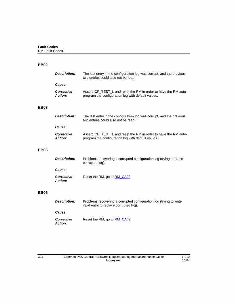
Fault CodesRM Fault Codes
324 Experion PKS Control Hardware Troubleshooting and Maintenance Guide R210Honeywell 10/04
EB02
Description: The last entry in the configuration log was corrupt, and the previoustwo entries could also not be read.
Cause:
CorrectiveAction:
Assert ICP_TEST_L and reset the RM in order to have the RM auto-program the configuration log with default values.
EB03
Description: The last entry in the configuration log was corrupt, and the previoustwo entries could also not be read.
Cause:
CorrectiveAction:
Assert ICP_TEST_L and reset the RM in order to have the RM auto-program the configuration log with default values.
EB05
Description: Problems recovering a corrupted configuration log (trying to erasecorrupted log).
Cause:
CorrectiveAction:
Reset the RM, go to RM_CA02.
EB06
Description: Problems recovering a corrupted configuration log (trying to writevalid entry to replace corrupted log).
Cause:
CorrectiveAction:
Reset the RM, go to RM_CA02.
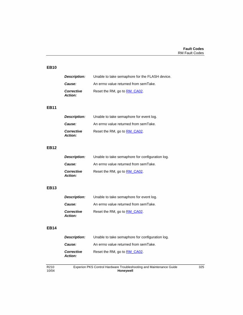
Fault CodesRM Fault Codes
R210 Experion PKS Control Hardware Troubleshooting and Maintenance Guide 32510/04 Honeywell
EB10
Description: Unable to take semaphore for the FLASH device.
Cause: An errno value returned from semTake.
CorrectiveAction:
Reset the RM, go to RM_CA02.
EB11
Description: Unable to take semaphore for event log.
Cause: An errno value returned from semTake.
CorrectiveAction:
Reset the RM, go to RM_CA02.
EB12
Description: Unable to take semaphore for configuration log.
Cause: An errno value returned from semTake.
CorrectiveAction:
Reset the RM, go to RM_CA02.
EB13
Description: Unable to take semaphore for event log.
Cause: An errno value returned from semTake.
CorrectiveAction:
Reset the RM, go to RM_CA02.
EB14
Description: Unable to take semaphore for configuration log.
Cause: An errno value returned from semTake.
CorrectiveAction:
Reset the RM, go to RM_CA02.
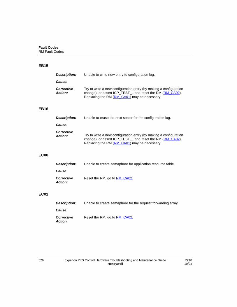
Fault CodesRM Fault Codes
326 Experion PKS Control Hardware Troubleshooting and Maintenance Guide R210Honeywell 10/04
EB15
Description: Unable to write new entry to configuration log.
Cause:
CorrectiveAction:
Try to write a new configuration entry (by making a configurationchange), or assert ICP_TEST_L and reset the RM (RM_CA02).Replacing the RM (RM_CA01) may be necessary.
EB16
Description: Unable to erase the next sector for the configuration log.
Cause:
CorrectiveAction: Try to write a new configuration entry (by making a configuration
change), or assert ICP_TEST_L and reset the RM (RM_CA02).Replacing the RM (RM_CA01) may be necessary.
EC00
Description: Unable to create semaphore for application resource table.
Cause:
CorrectiveAction:
Reset the RM, go to RM_CA02.
EC01
Description: Unable to create semaphore for the request forwarding array.
Cause:
CorrectiveAction:
Reset the RM, go to RM_CA02.
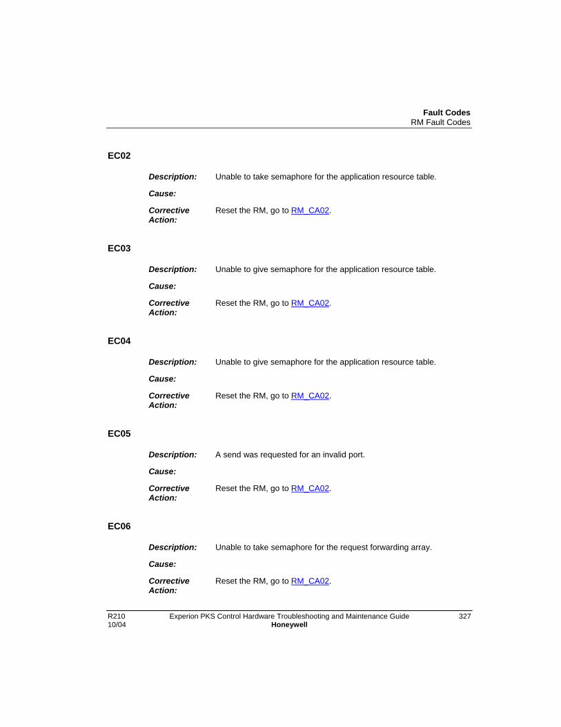
Fault CodesRM Fault Codes
R210 Experion PKS Control Hardware Troubleshooting and Maintenance Guide 32710/04 Honeywell
EC02
Description: Unable to take semaphore for the application resource table.
Cause:
CorrectiveAction:
Reset the RM, go to RM_CA02.
EC03
Description: Unable to give semaphore for the application resource table.
Cause:
CorrectiveAction:
Reset the RM, go to RM_CA02.
EC04
Description: Unable to give semaphore for the application resource table.
Cause:
CorrectiveAction:
Reset the RM, go to RM_CA02.
EC05
Description: A send was requested for an invalid port.
Cause:
CorrectiveAction:
Reset the RM, go to RM_CA02.
EC06
Description: Unable to take semaphore for the request forwarding array.
Cause:
CorrectiveAction:
Reset the RM, go to RM_CA02.

Fault CodesRM Fault Codes
328 Experion PKS Control Hardware Troubleshooting and Maintenance Guide R210Honeywell 10/04
EC07
Description: Unable to create link consumer for the multicast connection.
Cause:
CorrectiveAction:
Reset the RM, go to RM_CA02.
ED00
Description: Unable to start watchdog used for updating the partner’s currenttime.
Cause:
CorrectiveAction:
Reset the RM, go to RM_CA02.
ED10
Description: Unable to allocate a combuf for sending new offset from CST.
Cause:
CorrectiveAction:
None.
ED11
Description: Unable to allocate an UCMM resource for sending time update topartner.
Cause:
CorrectiveAction:
None.

Fault CodesRM Fault Codes
R210 Experion PKS Control Hardware Troubleshooting and Maintenance Guide 32910/04 Honeywell
ED12
Description: Invalid response handle received.
Cause:
CorrectiveAction:
Reset the RM, go to RM_CA02.
ED13
Description: Unable to start watchdog used for updating the partner’s currenttime.
Cause:
CorrectiveAction:
Reset the RM, go to RM_CA02.
ED14
Description: Unable to allocate a combuf for sending new time to partner WCTobject.
Cause:
CorrectiveAction:
None.
ED20
Description: Unable to take semaphore used synchronize the wall clock timetask.
Cause: An errno value returned from semTake.
CorrectiveAction:
Reset the RM, go to RM_CA02.

Fault CodesRM Fault Codes
330 Experion PKS Control Hardware Troubleshooting and Maintenance Guide R210Honeywell 10/04
ED21
Description: Unable to allocate combuf for sending GET_ATTRIBUTES_ALLrequest to partner WCT object.
Cause: An errno value returned from semTake.
CorrectiveAction:
None.
ED22
Description: Unable to allocate an UCMM resource for sendingGET_ATTRIBUTES_ALL request to partner WCT object.
Cause:
CorrectiveAction:
None.
ED23
Description: Unable to start watchdog used for updating the partner’s currenttime.
Cause: An errno value returned from wdStart.
CorrectiveAction:
Reset the RM, go to RM_CA02.
ED30
Description: Unable to read application revision from configuration log.
Cause: An errno value returned from cfgReadAppRevision.
CorrectiveAction:
None.

Fault CodesRM Fault Codes
R210 Experion PKS Control Hardware Troubleshooting and Maintenance Guide 33110/04 Honeywell
ED31
Description: Unable to write application revision to configuration log.
Cause: An errno value returned from cfgWriteAppRevision.
CorrectiveAction:
None.
EE00
Description: DC_FAIL Interrupt has occured.
Cause: • Value of the hardware watchdog timer register.
• RM watchdog count value.
CorrectiveAction:
If the chassis did not actually power down, reset the RM. Go toRM_CA02.
EF00
Description: Unable to post event to the NVS Object.
Cause: An errno value returned from msgQSend.
CorrectiveAction:
Reset the RM, go to RM_CA02.
EF10
Description: Received unhandled event.
Cause: Event type received.
CorrectiveAction:
Reset the RM, go to RM_CA02.
Fault CodesRM Fault Codes
332 Experion PKS Control Hardware Troubleshooting and Maintenance Guide R210Honeywell 10/04
EF11
Description: Error when receiving messages from message queue.
Cause: An errno value returned from msgQReceive.
CorrectiveAction:
Reset the RM, go to RM_CA02.
EF20
Description: Unable to read message from NVS Task message queue.
Cause: An errno value returned from msgQReceive.
CorrectiveAction:
Reset the RM, go to RM_CA02.
EF21
Description: Unable to prepare response buffer for an update service request.
Cause:
CorrectiveAction:
None.
EF22
Description: The pointer to the response routine was NULL.
Cause:
CorrectiveAction:
Reset the RM, go to RM_CA02.
EF23
Description: Unable to prepare response buffer for a transfer service request.
Cause:
CorrectiveAction:
None.

Fault CodesRM Fault Codes
R210 Experion PKS Control Hardware Troubleshooting and Maintenance Guide 33310/04 Honeywell
EF24
Description: The pointer to the response routine was NULL. Unable to sendresponse to transfer service request.
Cause:
CorrectiveAction:
None.
EF30
Description: Received unknown event.
Cause: Event received.
CorrectiveAction:
None.
EG02
Description: A second major unrecoverable fault has been declared.
Cause: • Fault code of second major fault declared.
• First argument of second major fault declared.
CorrectiveAction:
Follow the action of the first major fault declared (probably reset theRM).
EG10
Description: The default exception handler was called by the OS.
Cause:
CorrectiveAction:
Reset the RM, go to RM_CA02.

Fault CodesRM Fault Codes
334 Experion PKS Control Hardware Troubleshooting and Maintenance Guide R210Honeywell 10/04
EG11
Description: The reboot handler was called by the OS.
Cause:
CorrectiveAction:
Reset the RM, go to RM_CA02.
EH01
Description: Unable to create a message queue for Self Test Object events.
Cause: An errno value returned from msgQCreate.
CorrectiveAction:
Reset the RM, go to RM_CA02.
EH02
Description: Unable to spawn the Self Test Object event handling task.
Cause: An errno value returned from taskSpawn.
CorrectiveAction:
Reset the RM, go to RM_CA02.
EH03
Description: Unable to create a watchdog timer for use in timing Self Test Objectoperations.
Cause: An errno value returned from wdCreate.
CorrectiveAction:
Reset the RM, go to RM_CA02.
Fault CodesRM Fault Codes
R210 Experion PKS Control Hardware Troubleshooting and Maintenance Guide 33510/04 Honeywell
EH04
Description: Unable to create a semaphore for use in Self Test Objectscheduling.
Cause: An errno value returned from semBCreate.
CorrectiveAction:
Reset the RM, go to RM_CA02.
EH05
Description: Unable to create a semaphore for use in coordinating Self TestObject operations with Switchovers.
Cause: An errno value returned from semBCreate.
CorrectiveAction:
Reset the RM, go to RM_CA02.
EH06
Description: Unable to spawn the Self Test Object test scheduling task.
Cause: An errno value returned from taskSpawn.
CorrectiveAction:
Reset the RM, go to RM_CA02.
EH07
Description: Unable to register the Self Test Object with the ICP Toolkit(Backplane comm).
Cause: An errno value returned from classRegister.
CorrectiveAction:
Reset the RM, go to RM_CA02.
Fault CodesRM Fault Codes
336 Experion PKS Control Hardware Troubleshooting and Maintenance Guide R210Honeywell 10/04
EH0A
Description: A failure occurred in a Self Test Object attempt to take a semaphorewhich blocks self tests during a switchover.
Cause: An errno value returned from semTake.
CorrectiveAction:
Reset the RM, go to RM_CA02.
EH10
Description: Error occurred in reception of an event message.
Cause: An errno value returned from msgQReceive.
CorrectiveAction:
Reset the RM, go to RM_CA02.
EH11
Description: Failed in attempt to forward events to partner RM.
Cause: Status (no zero) value returned from stoForwardFaultEvent.
CorrectiveAction:
Reset the RM, go to RM_CA02.
EH12
Description: An invalid event type accompanied a request to forward an event tothe partner RM.
Cause: • Event type which accompanied request.
• Current errno value.
CorrectiveAction:
Reset the RM, go to RM_CA02.
Fault CodesRM Fault Codes
R210 Experion PKS Control Hardware Troubleshooting and Maintenance Guide 33710/04 Honeywell
EH20
Description: Failed attempt to allocate a comm buffer.
Cause: An errno value returned from ComBuf_Malloc.
CorrectiveAction:
None.
EH21
Description: Failed attempt to open a connection to the partner RM.
Cause: An errno value returned from bcUcmmOpen.
CorrectiveAction:
None.
EH22
Description: Failed attempt to send a request to the partner RM.
Cause: An errno value returned from bcUcmmSendRequest.
CorrectiveAction:
None.
EH23
Description: Failed (BAD HANDLE) attempt to close connection with the partnerRM.
Cause: An errno value returned from bcUcmmClose.
CorrectiveAction:
Reset the RM, go to RM_CA02.

Fault CodesRM Fault Codes
338 Experion PKS Control Hardware Troubleshooting and Maintenance Guide R210Honeywell 10/04
EH24
Description: Failed (BAD HANDLE) attempt to close connection with the partnerRM.
Cause: An errno value returned from bcUcmmClose.
CorrectiveAction:
Reset the RM, go to RM_CA02.
EH25
Description: Failed (BAD HANDLE) attempt to close connection with the partnerRM.
Cause: An errno value returned from bcUcmmClose.
CorrectiveAction:
Reset the RM, go to RM_CA02.
EH26
Description: Failed attempt to recycle connection with the partner RM.
Cause: An errno value returned from bcUcmmRecycle.
CorrectiveAction:
Reset the RM, go to RM_CA02.
EH27
Description: Failed (BAD HANDLE) attempt to close connection with the partnerRM.
Cause: An errno value returned from bcUcmmClose.
CorrectiveAction:
Reset the RM, go to RM_CA02.

Fault CodesRM Fault Codes
R210 Experion PKS Control Hardware Troubleshooting and Maintenance Guide 33910/04 Honeywell
EH28
Description: Invalid or false Secondary Device Status collection stateencountered while awaiting response from the partner RM.
Cause: State enumeration.
CorrectiveAction:
None.
EH29
Description: Failed (BAD HANDLE) attempt to close connection with the partnerRM.
Cause: An errno value returned from bcUcmmClose.
CorrectiveAction:
Reset the RM, go to RM_CA02.
EH2A
Description: A failure occurred in a Self Test Object’s preliminary attempt to takea semaphore which blocks this function during a switchover.
Cause: An errno value returned from semTake.
CorrectiveAction:
Reset the RM, go to RM_CA02.
EH2B
Description: A failure occurred in a Self Test Object’s final (just prior to sending arequest message) attempt to take a semaphore which blocks thisfunction during a switchover.
Cause: An errno value returned from semTake.
CorrectiveAction:
Reset the RM, go to RM_CA02.
Fault CodesRM Fault Codes
340 Experion PKS Control Hardware Troubleshooting and Maintenance Guide R210Honeywell 10/04
EH30
Description: Failed attempt to allocate a comm buffer.
Cause: An errno value returned from ComBuf_Malloc.
CorrectiveAction:
None.
EH3A
Description: A failure occurred in a Self Test Object’s preliminary attempt to takea semaphore which blocks this function during a switchover.
Cause: An errno value returned from semTake.
CorrectiveAction:
Reset the RM, go to RM_CA02.
EH31
Description: Failed attempt to open a connection to the partner RM.
Cause: An errno value returned from bcUcmmOpen.
CorrectiveAction:
None.
EH32
Description: Failed attempt to send a request to the partner RM.
Cause: An errno value returned from bcUcmmSendRequest.
CorrectiveAction:
None.

Fault CodesRM Fault Codes
R210 Experion PKS Control Hardware Troubleshooting and Maintenance Guide 34110/04 Honeywell
EH33
Description: Failed (BAD HANDLE) attempt to close connection with the partnerRM.
Cause: An errno value returned from bcUcmmClose.
CorrectiveAction:
Reset the RM, go to RM_CA02.
EH34
Description: Failed (BAD HANDLE) attempt to close connection with the partnerRM.
Cause: An errno value returned from bcUcmmClose.
CorrectiveAction:
Reset the RM, go to RM_CA02.
EH35
Description: Failed (BAD HANDLE) attempt to close connection with the partnerRM.
Cause: An errno value returned from bcUcmmClose.
CorrectiveAction:
Reset the RM, go to RM_CA02.
EH36
Description: Failed attempt to recycle connection with the partner RM.
Cause: An errno value returned from bcUcmmRecycle.
CorrectiveAction:
Reset the RM, go to RM_CA02.
Fault CodesRM Fault Codes
342 Experion PKS Control Hardware Troubleshooting and Maintenance Guide R210Honeywell 10/04
EH37
Description: Failed (BAD HANDLE) attempt to close connection with the partnerRM.
Cause:
CorrectiveAction:
Reset the RM, go to RM_CA02.
EH38
Description: Invalid or false Secondary SYS_FAIL_L Subsystem Status collectionstate encountered while awaiting response from the partner RM.
Cause: State enumeration.
CorrectiveAction:
None.
EH39
Description: Failed (BAD HANDLE) attempt to close connection with the partnerRM.
Cause: An errno value returned from bcUcmmClose.
CorrectiveAction:
Reset the RM, go to RM_CA02.
EH40
Description: Failed attempt to allocate a comm buffer.
Cause: An errno value returned from ComBuf_Malloc.
CorrectiveAction:
None.

Fault CodesRM Fault Codes
R210 Experion PKS Control Hardware Troubleshooting and Maintenance Guide 34310/04 Honeywell
EH41
Description: Failed attempt to open a connection to the partner RM.
Cause: An errno value returned from bcUcmmOpen.
CorrectiveAction:
None.
EH42
Description: Failed attempt to send a request to the partner RM.
Cause: An errno value returned from bcUcmmSendRequest.
CorrectiveAction:
None.
EH43
Description: Failed (BAD HANDLE) attempt to close connection with the partnerRM.
Cause: An errno value returned from bcUcmmClose.
CorrectiveAction:
Reset the RM, go to RM_CA02.
EH44
Description: Failed (BAD HANDLE) attempt to close connection with the partnerRM.
Cause: An errno value returned from bcUcmmClose.
CorrectiveAction:
Reset the RM, go to RM_CA02.
Fault CodesRM Fault Codes
344 Experion PKS Control Hardware Troubleshooting and Maintenance Guide R210Honeywell 10/04
EH45
Description: Failed (BAD HANDLE) attempt to close connection with the partnerRM.
Cause: An errno value returned from bcUcmmClose.
CorrectiveAction:
Reset the RM, go to RM_CA02.
EH46
Description: Failed attempt to recycle connection with the partner RM.
Cause: An errno value returned from bcUcmmClose.
CorrectiveAction:
Reset the RM, go to RM_CA02.
EH47
Description: Failed (BAD HANDLE) attempt to close connection with the partnerRM.
Cause:
CorrectiveAction:
Reset the RM, go to RM_CA02.
EH48
Description: Invalid or false Forward Fault Event collection state encounteredwhile awaiting response from the partner RM.
Cause: State enumeration.
CorrectiveAction:
None.

Fault CodesRM Fault Codes
R210 Experion PKS Control Hardware Troubleshooting and Maintenance Guide 34510/04 Honeywell
EH49
Description: Failed (BAD HANDLE) attempt to close connection with the partnerRM.
Cause: An errno value returned from bcUcmmClose.
CorrectiveAction:
Reset the RM, go to RM_CA02.
EH4A
Description: A failure occurred in a Self Test Object’s preliminary attempt to takea semaphore which blocks this function during a switchover.
Cause: An errno value returned from semTake.
CorrectiveAction:
Reset the RM, go to RM_CA02.
EH50
Description: Failed attempt to allocate a comm buffer.
Cause: An errno value returned from ComBuf_Malloc.
CorrectiveAction:
None.
EH5A
Description: A failure occurred in a Self Test Object’s preliminary attempt to takea semaphore which blocks this function during a switchover.
Cause: An errno value returned from semTake.
CorrectiveAction:
Reset the RM, go to RM_CA02.

Fault CodesRM Fault Codes
346 Experion PKS Control Hardware Troubleshooting and Maintenance Guide R210Honeywell 10/04
EH51
Description: Failed attempt to open a connection to the partner RM.
Cause: • Status value returned from bcUcmmOpen.
• An errno value returned from bcUcmmOpen.
CorrectiveAction:
None.
EH52
Description: Failed attempt to send a request to the partner RM.
Cause: • Status value returned from bcUcmmSendRequest.
• An errno value returned from bcUcmmSendRequest.
CorrectiveAction:
None.
EH53
Description: Status of test response not SUCCESS.
Cause: • Status value returned.
• An errno value returned.
CorrectiveAction:
None.
EH60
Description: Failed attempt to post an event in the Self Test Object Event Queue.
Cause: • Event type.
• An errno value returned from msgQSend.
CorrectiveAction:
Reset the RM, go to RM_CA02.

Fault CodesRM Fault Codes
R210 Experion PKS Control Hardware Troubleshooting and Maintenance Guide 34710/04 Honeywell
EH70
Description: Device Status Read - Problem encountered in preparing a responsebuffer.
Cause:
CorrectiveAction:
None.
EH71
Description: Device Status Read - Routine handling a prepared responseencountered a fault.
Cause:
CorrectiveAction:
Reset the RM, go to RM_CA02.
EH72
Description: SYS_FAIL Results Read - Problem encountered in preparing aresponse buffer
Cause:
CorrectiveAction:
None.
EH73
Description: SYS_FAIL Results Read - Routine handling a prepared responseencountered a fault.
Cause:
CorrectiveAction:
Reset the RM, go to RM_CA02.

Fault CodesRM Fault Codes
348 Experion PKS Control Hardware Troubleshooting and Maintenance Guide R210Honeywell 10/04
EH74
Description: Reset Test Stats - Problem encountered in preparing a responsebuffer.
Cause:
CorrectiveAction:
None.
EH75
Description: Reset Test Stats - Routine handling a prepared responseencountered a fault
Cause:
CorrectiveAction:
Reset the RM, go to RM_CA02.
EH76
Description: Set User Relay - Problem encountered in preparing a responsebuffer
Cause:
CorrectiveAction:
None.
EH77
Description: Set User Relay - Routine handling a prepared responseencountered a fault.
Cause:
CorrectiveAction:
Reset the RM, go to RM_CA02.

Fault CodesRM Fault Codes
R210 Experion PKS Control Hardware Troubleshooting and Maintenance Guide 34910/04 Honeywell
EH78
Description: STO Loopback Test - Problem encountered in preparing a responsebuffer.
Cause:
CorrectiveAction:
None.
EH79
Description: STO Loopback Test - Routine handling a prepared responseencountered a fault.
Cause:
CorrectiveAction:
Reset the RM, go to RM_CA02.
EH7A
Description: Forward Partner Fault - Problem encountered in preparing aresponse buffer.
Cause:
CorrectiveAction:
None.
EH7B
Description: Forward Partner Fault - Invalid event type.
Cause: Event type.
CorrectiveAction:
Reset the RM, go to RM_CA02.

Fault CodesRM Fault Codes
350 Experion PKS Control Hardware Troubleshooting and Maintenance Guide R210Honeywell 10/04
EH7C
Description: Forward partner Fault - Routine handling a prepared responseencountered a fault.
Cause:
CorrectiveAction:
Reset the RM, go to RM_CA02.
EH7D
Description: A failure occurred in a outsdie process’s attempt to take asemaphore that would block testing during a switchover.
Cause: An errno value returned from semTake.
CorrectiveAction:
Reset the RM, go to RM_CA02.
EHA1
Description: Invalid test pulse state returned after an attempted SYS_FAIL_Ltest.
Cause: Test pulse state enumeration.
CorrectiveAction:
Reset the RM, go to RM_CA02.
EHA2
Description: Failed attempt to allocate a comm buffer for use in sending aSYS_FAIL_L test request to another module.
Cause: An errno value returned from ComBuf_Malloc.
CorrectiveAction:
None.
Fault CodesRM Fault Codes
R210 Experion PKS Control Hardware Troubleshooting and Maintenance Guide 35110/04 Honeywell
EHA3
Description: Failed attempt to open a connection to another module for the sakeof sending a test request.
Cause:
CorrectiveAction:
None.
EHA4
Description: Failed attempt to send a test request to another module.
Cause: An errno value returned from UCMM_SendRequest.
CorrectiveAction:
None.
EHA5
Description: Failed attempt to close a connection following the unsuccessfulsending of a test request to another module.
Cause:
CorrectiveAction:
Reset the RM, go to RM_CA02.
EHA6
Description: Failed attempt to close a connection following a NOT READYresponse to a test request to another module.
Cause:
CorrectiveAction:
Reset the RM, go to RM_CA02.
Fault CodesRM Fault Codes
352 Experion PKS Control Hardware Troubleshooting and Maintenance Guide R210Honeywell 10/04
EHA7
Description: Failed attempt to close a connection following a READY response toa test request to another module.
Cause:
CorrectiveAction:
Reset the RM, go to RM_CA02.
EHA8
Description: Failed attempt to close a connection following a COMMS ERROR orNEEDS RETRY response to a test request to another module.
Cause:
CorrectiveAction:
Reset the RM, go to RM_CA02.
EHA9
Description: Invalid test status response state encountered regarding a testrequest to another module.
Cause:
CorrectiveAction:
Reset the RM, go to RM_CA02.
EHAA
Description: Failed attempt to allocate a comm buffer for use in sending aSYS_FAIL_L test status request to another module.
Cause:
CorrectiveAction:
None.

Fault CodesRM Fault Codes
R210 Experion PKS Control Hardware Troubleshooting and Maintenance Guide 35310/04 Honeywell
EHAB
Description: Failed attempt to open a connection to another module for the sakeof sending a test status request.
Cause:
CorrectiveAction:
None.
EHAC
Description: Failed attempt to send a test status request to another module.
Cause:
CorrectiveAction:
None.
EHAD
Description: Failed attempt to close a connection following the unsuccessfulsending of a test status request to another module.
Cause:
CorrectiveAction:
Reset the RM, go to RM_CA02.
EHAE
Description: Failed attempt to close a connection following an UNSUPPORTED,BUSY, or COMPLETE response to a test request to anothermodule.
Cause:
CorrectiveAction:
Reset the RM, go to RM_CA02.
Fault CodesRM Fault Codes
354 Experion PKS Control Hardware Troubleshooting and Maintenance Guide R210Honeywell 10/04
EHAF
Description: Failed attempt to close a connection following an NEEDS RETRY,WAIT, or COMM ERR, or unrecognized response to a test requestto another module.
Cause:
CorrectiveAction:
Reset the RM, go to RM_CA02.
EHAG
Description: Local SYS_FAIL_L input circuitry has failed local loopback test.Specifics on cause are unknown.
Cause:
CorrectiveAction:
Replace RM (RM_CA01) at earliest opportunity. This RM will notsupport Synchronization if in a Secondary.
EHAH
Description: Local SYS_FAIL_L input circuitry has failed local loopback test.Interrupt portion was found to be faulty.
Cause:
CorrectiveAction:
Replace RM (RM_CA01) at earliest opportunity. This RM will notsupport Synchronization if in a Secondary.
EHAJ
Description: Local SYS_FAIL_L input circuitry has failed local loopback test.Status read portion was found to be faulty.
Cause:
CorrectiveAction:
Replace RM (RM_CA01) at earliest opportunity. This RM will notsupport Synchronization if in a Secondary.

Fault CodesRM Fault Codes
R210 Experion PKS Control Hardware Troubleshooting and Maintenance Guide 35510/04 Honeywell
EHAK
Description: Local SYS_FAIL_L input circuitry has failed local loopback test.Local driver portion was found to be faulty.
Cause:
CorrectiveAction:
Replace RM (RM_CA01) at earliest opportunity. This RM will notsupport Synchronization if in a Secondary.
EHAL
Description: Local SYS_FAIL_L input circuitry has failed local loopback test.Status read portion was found to be faulty.
Cause:
CorrectiveAction:
Replace RM (RM_CA01) at earliest opportunity. This RM will notsupport Synchronization if in a Secondary.
EHAM
Description: Local SYS_FAIL_L input circuitry has failed local loopback test.Status read occurred, but interrupt did not.
Cause:
CorrectiveAction:
Replace RM (RM_CA01) at earliest opportunity. This RM will notsupport Synchronization if in a Secondary.
EHAN
Description: Local SYS_FAIL_L input circuitry has failed local loopback test.Invalid test results.
Cause:
CorrectiveAction:
Reset the RM, go to RM_CA02. If error persists, contact HoneywellTAC.

Fault CodesRM Fault Codes
356 Experion PKS Control Hardware Troubleshooting and Maintenance Guide R210Honeywell 10/04
EHAP
Description: A failure occurred in a Self Test Object’s attempt to take asemaphore which would block scanning for new modules during aswitchover.
Cause:
CorrectiveAction:
Reset the RM, go to RM_CA02.
EHAR
Description: A failure occurred in a Self Test Object’s attempt to take asemaphore which would block SYS_FAIL_L assertion testing duringa switchover.
Cause: An errno value returned from semTake.
CorrectiveAction:
Reset the RM, go to RM_CA02.
EHAT
Description: A failure occurred in a Self Test Object’s preliminary attempt to takea semaphore which blocks the sending of a test status request toanother module during a switchover.
Cause: An errno value returned from semTake.
CorrectiveAction:
Reset the RM, go to RM_CA02.
EHAV
Description: A failure occurred in a Self Test Object’s attempt to take asemaphore which would block sending a test request to anothermodule during a switchover.
Cause: An errno value returned from semTake.
CorrectiveAction:
Reset the RM, go to RM_CA02.

Fault CodesRM Fault Codes
R210 Experion PKS Control Hardware Troubleshooting and Maintenance Guide 35710/04 Honeywell
EI00
Description: During a shutdown, a fault occurred while attempting to unregisterWorkstation Display Object with backplance communicationssubsystem.
Cause:
CorrectiveAction:
None. A shutdown situation.
EI01
Description: During a shutdown, a fault occurred while attempting to delete theWorkstation Display Object task.
Cause: An errno value returned from taskDelete.
CorrectiveAction:
None. A shutdown situation.
EI02
Description: During a shutdown, a fault occurred while attempting to delete aWorkstation Display Object semaphore.
Cause: An errno value returned from semDelete.
CorrectiveAction:
None. A shutdown situation.
EI03
Description: During a shutdown, a fault occurred while attempting to delete aWorkstation Display Object watchdog timer.
Cause: An errno value returned from wdDelete.
CorrectiveAction:
None. A shutdown situation.
Fault CodesRM Fault Codes
358 Experion PKS Control Hardware Troubleshooting and Maintenance Guide R210Honeywell 10/04
EI10
Description: A failure occurred in a Workstation Display Object attempt to start ascheduling (watchdog) semaphore.
Cause: An errno value returned from wdStart.
CorrectiveAction:
Reset the RM, go to RM_CA02.
EI40
Description: A failure occurred in a Workstation Display Object attempt to start ascheduling (watchdog) semaphore.
Cause: An errno value returned from wdStart.
CorrectiveAction:
Reset the RM, go to RM_CA02.
EI50
Description: A failure occurred in a Workstation Display Object attempt to read allRM Configuration Data (via cfgReadAllData).
Cause:
CorrectiveAction:
Reset the RM, go to RM_CA02.
EI51
Description: A failure occurred in a Workstation Display Object attempt to writeall RM Configuration Data (via cfgWriteNewData).
Cause:
CorrectiveAction:
Reset the RM, go to RM_CA02.
Fault CodesRM Fault Codes
R210 Experion PKS Control Hardware Troubleshooting and Maintenance Guide 35910/04 Honeywell
EI52
Description: A failure occurred in a Workstation Display Object attempt toprepare a response buffer.
Cause:
CorrectiveAction:
Reset the RM, go to RM_CA02.
EI53
Description: A failure occurred in a Workstation Display Object call to theresponse handling routine.
Cause:
CorrectiveAction:
Reset the RM, go to RM_CA02.
EI60
Description: A failure occurred in a Workstation Display Object attempt toinitialize its attributes.
Cause:
CorrectiveAction:
Reset the RM, go to RM_CA02.
EI61
Description: A failure occurred in a Workstation Display Object attempt to createa scheduling watchdog timer.
Cause:
CorrectiveAction:
Reset the RM, go to RM_CA02.

Fault CodesRM Fault Codes
360 Experion PKS Control Hardware Troubleshooting and Maintenance Guide R210Honeywell 10/04
EI62
Description: A failure occurred in a Workstation Display Object attempt to createa scheduling semaphore.
Cause:
CorrectiveAction:
Reset the RM, go to RM_CA02.
EI63
Description: A failure occurred in a Workstation Display Object attempt to spawnitself.
Cause:
CorrectiveAction:
Reset the RM, go to RM_CA02.
EI64
Description: A failure occurred in a Workstation Display Object attempt to registerwith the comm ports.
Cause:
CorrectiveAction:
Reset the RM, go to RM_CA02.
EI70
Description: A failure occurred in a Workstation Display Object attempt to start ascheduling watchdog timer.
Cause: An errno value returned from wdStart.
CorrectiveAction:
Reset the RM, go to RM_CA02.
Fault CodesRM Fault Codes
R210 Experion PKS Control Hardware Troubleshooting and Maintenance Guide 36110/04 Honeywell
EI71
Description: A failure occurred in a Workstation Display Object attempt to take ascheduling semaphore.
Cause:
CorrectiveAction:
Reset the RM, go to RM_CA02.
EI72
Description: A failure occurred in a Workstation Display Object request to otherRM objects to refresh their stale data.
Cause: An errno value returned from semTake.
CorrectiveAction:
Reset the RM, go to RM_CA02.
EI73
Description: A failure occurred in a Workstation Display Object attempt todetermine its next refresh delay.
Cause:
CorrectiveAction:
Reset the RM, go to RM_CA02.
EI74
Description: A failure occurred in a Workstation Display Object attempt to start ascheduling watchdog timer.
Cause:
CorrectiveAction:
Reset the RM, go to RM_CA02.

Fault CodesRM Fault Codes
362 Experion PKS Control Hardware Troubleshooting and Maintenance Guide R210Honeywell 10/04
EI75
Description: A failure occurred in a Workstation Display Object attempt to take ascheduling semaphore.
Cause:
CorrectiveAction:
Reset the RM, go to RM_CA02.
EI80
Description: A failure occurred in a Workstation Display Object request to BCO toupdates stale attributes.
Cause:
CorrectiveAction:
Reset the RM, go to RM_CA02.
EI81
Description: A failure occurred in a Workstation Display Object request to DevceObject to updates stale attributes.
Cause:
CorrectiveAction:
Reset the RM, go to RM_CA02.
EI90
Description: A failure occurred in a Workstation Display Object attempt to readRM Revision (cfgReadRevision).
Cause:
CorrectiveAction:
Reset the RM, go to RM_CA02.
Fault CodesRM Fault Codes
R210 Experion PKS Control Hardware Troubleshooting and Maintenance Guide 36310/04 Honeywell
EIZ0
Description: A failure occurred in a Workstation Display Object attempt to take ascheduling (watchdog) semaphore.
Cause: An errno value returned from wdCreate.
CorrectiveAction:
Reset the RM, go to RM_CA02.
EJ00
Description: Unable to read serial number from configuration log.
Cause:
CorrectiveAction:
Reset ( RM_CA02) or replace the RM (RM_CA01).
EJ01
Description: Unable to read the vendor ID from the configuration log.
Cause:
CorrectiveAction:
Reset ( RM_CA02) or replace the RM (RM_CA01).
EJ02
Description: Unable to register the ICP Object with the ICP Toolkit.
Cause:
CorrectiveAction:
Reset the RM, go to RM_CA02.

Fault CodesRM Fault Codes
364 Experion PKS Control Hardware Troubleshooting and Maintenance Guide R210Honeywell 10/04
EJ10
Description: Unable to register the ICP Object with the ICP Toolkit.
Cause:
CorrectiveAction:
None.
EJ11
Description: Response routine for the SET_ATTRIBUTES_ALL request is NULL.
Cause:
CorrectiveAction:
Reset the RM, go to RM_CA02.
EJ12
Description: Unable to prepare a response buffer for a RESET request.
Cause:
CorrectiveAction:
None.
EJ13
Description: Response routine for the RESET request is NULL.
Cause:
CorrectiveAction:
None.
EJ20
Description: A supervisory request to the ICP ASIC failed.
Cause: State of supervisory control block.
CorrectiveAction:
Reset the RM, go to RM_CA02.

Fault CodesRM Fault Codes
R210 Experion PKS Control Hardware Troubleshooting and Maintenance Guide 36510/04 Honeywell
EK10
Description: Error sending event to main watchdog manager queue.
Cause: An errno value returned from msgQSend.
CorrectiveAction:
Reset the RM, go to RM_CA02.
EK21
Description: RM hardware watchdog timer test failed. The watchdog timer wasdisabled after being enabled.
Cause:
CorrectiveAction:
Reset the RM, go to RM_CA02.
EK22
Description: RM hardware watchdog timer test failed. The watchdog timer wasnot counting.
Cause:
CorrectiveAction:
Reset the RM, go to RM_CA02.
EK23
Description: Error receiving event from main watchdog manager queue.
Cause: An errno value returned from msgQReceive.
CorrectiveAction:
Reset the RM, go to RM_CA02.

Fault CodesRM Fault Codes
366 Experion PKS Control Hardware Troubleshooting and Maintenance Guide R210Honeywell 10/04
EK24
Description: All of the asynchronous tasks being checked did not report to thewatchdog manager on time.
Cause: • Task number (upper 16 bits); number of watchdog kicks (lower16 bits).
• Asynchronous tasks reporting.
CorrectiveAction:
Reset the RM, go to RM_CA02.
EK25
Description: The timer clock task did not report to the watchdog manager ontime.
Cause: • Task number (upper 16 bits); number of watchdog kicks (lower16 bits).
• Synchronous tasks reporting.
CorrectiveAction:
Reset the RM, go to RM_CA02.
EK26
Description: The self-test object task did not report to the watchdog manager ontime.
Cause: • Task number (upper 16 bits); number of watchdog kicks (lower16 bits).
• Synchronous tasks reporting.
CorrectiveAction:
Reset the RM, go to RM_CA02.

Fault CodesRM Fault Codes
R210 Experion PKS Control Hardware Troubleshooting and Maintenance Guide 36710/04 Honeywell
EK27
Description: The collect attributes task did not report to the watchdog manageron time.
Cause: • Task number (upper 16 bits); number of watchdog kicks (lower16 bits).
• Synchronous tasks reporting.
CorrectiveAction:
Reset the RM, go to RM_CA02.
EK28
Description: The wall clock time object task did not report to the watchdogmanager on time.
Cause: • Task number (upper 16 bits); number of watchdog kicks (lower16 bits).
• Asynchronous tasks reporting.
CorrectiveAction:
Reset the RM, go to RM_CA02.
EK29
Description: The workstation display object task did not report to the watchdogmanager on time.
Cause: • Task number (upper 16 bits); number of watchdog kicks (lower16 bits).
• Asynchronous tasks reporting.
CorrectiveAction:
Reset the RM, go to RM_CA02.
Fault CodesRM Fault Codes
368 Experion PKS Control Hardware Troubleshooting and Maintenance Guide R210Honeywell 10/04
EK2A
Description: Unknown task index.
Cause: Task index.
CorrectiveAction:
Reset the RM, go to RM_CA02.
EK2B
Description: Unknown event for watchdog manager to process.
Cause: Event.
CorrectiveAction:
Reset the RM, go to RM_CA02.
EK2C
Description: The event log object task did not report to the watchdog manager ontime. Primary RM encounters a major shutdown fault during (power-cycle) switchover.
Cause: • Task number (upper 16 bits); number of watchdog kicks (lower16 bits).
• Asynchronous tasks reporting.
CorrectiveAction:
Reset the RM, go to RM_CA02. If problem persists, go toGEN_CA01.
EK40
Description: Error starting the watchdog for checking tasks.
Cause: An errno value returned from wdStart.
CorrectiveAction:
Reset the RM, go to RM_CA02.
Fault CodesRM Fault Codes
R210 Experion PKS Control Hardware Troubleshooting and Maintenance Guide 36910/04 Honeywell
EK70
Description: Error starting the watchdog for kicking the hardware watchdog.
Cause: An errno value returned from wdStart.
CorrectiveAction:
Reset the RM, go to RM_CA02.
EKA0
Description: Error sending watchdog ‘report in’ event to backup communicationsunconnected message manager receive task.
Cause: An errno value returned from msgQSend.
CorrectiveAction:
Reset the RM, go to RM_CA02.
EKC0
Description: Error sending watchdog ‘report in’ event to backup communicationslink producer receive task.
Cause: An errno value returned from msgQSend.
CorrectiveAction:
Reset the RM, go to RM_CA02.
EKD0
Description: Error sending watchdog ‘report in’ event to ICP link producer receivetask.
Cause: An errno value returned from msgQSend.
CorrectiveAction:
Reset the RM, go to RM_CA02.

Fault CodesRM Fault Codes
370 Experion PKS Control Hardware Troubleshooting and Maintenance Guide R210Honeywell 10/04
EKE0
Description: Error sending watchdog ‘report in’ event to ICP link consummerreceive task.
Cause: An errno value returned from msgQSend.
CorrectiveAction:
Reset the RM, go to RM_CA02.
EKF0
Description: Error sending watchdog ‘report in’ event to ICP link consummerreceive task.
Cause: An errno value returned from msgQSend.
CorrectiveAction:
Reset the RM, go to RM_CA02.
EKG0
Description: Error sending watchdog ‘report in’ event to ICP unconnectedmessage manager receive task.
Cause: An errno value returned from msgQSend.
CorrectiveAction:
Reset the RM, go to RM_CA02.
EKT1
Description: Unknown task index.
Cause: Task index.
CorrectiveAction:
Reset the RM, go to RM_CA02.
Fault CodesRM Fault Codes
R210 Experion PKS Control Hardware Troubleshooting and Maintenance Guide 37110/04 Honeywell
EKU0
Description: Unknown task index.
Cause: Task index.
CorrectiveAction:
Reset the RM, go to RM_CA02.

Fault CodesRM Fault Codes
372 Experion PKS Control Hardware Troubleshooting and Maintenance Guide R210Honeywell 10/04

R210 Experion PKS Control Hardware Troubleshooting and Maintenance Guide 37310/04 Honeywell
Experion PKS Notifications
CPM FB Generated Notifications
Backup State
Description: State Change Event generated by the secondary CPM to indicatethe CPM is executing in the secondary redundancy role.
Cause: Startup or role change (e.g. switchover) into the secondaryredundancy role.
CorrectiveAction:
N/A
Battery Not OK
Description: There are two types of batteries used for CPM memory retention: {1}the lithium battery in the front of the CPM and {2} the Ni-Cad BatteryExtension Module (BEM) residing in the chassis. This DiagnosticAlarm indicates either that {1} neither type of battery is present norof proper voltage or {2} both batteries are present and of propervoltage. Note that having two batteries (of proper voltage) present isa minor fault condition.
Cause: Defective battery or invalid battery configuration.
CorrectiveAction:
Replace defective battery or correct invalid battery configurationCPM_CA07.
Not Synchronized
Description: The primary and/or secondary CPM generates the NotSynchronized Diagnostic Alarm notification either upon redundancystartup (i.e. detection of RM) or detection of loss-of-synchronization.The primary and secondary CPM generates the Not Synchronizedreturn-to-normal notification once synchronization is achieved.
Cause: Many causes that are scrutinized within the corrective action.
CorrectiveAction:
Isolate reason for loss-of-synchronization CPM_CA03.

Experion PKS NotificationsCPM FB Generated Notifications
374 Experion PKS Control Hardware Troubleshooting and Maintenance Guide R210Honeywell 10/04
RAM Sweep Error(s)
Description: Diagnostic Alarm to indicate that a CPM run-time diagnostic wasunable to correct a DRAM single bit error.
Cause: Defective CPM memory.
CorrectiveAction:
Restart the CPM CPM_CA05.If problem persists, replace the CPMCPM_CA06.
RAM Scrub Errors
Description: Diagnostic Alarm to indicate that the CPM encountered more than10 single bit errors in one pass of the entire DRAM.
Cause: Defective CPM memory and/or high temperatures.
CorrectiveAction:
Restart the CPM CPM_CA05.If problem persists, replace the CPMCPM_CA06.
REDUN Chassis ID Unknown
Description: System Info Event to inform the user that the RM has not yet notifiedthe CPM in which physical chassis it resides.
Cause: This CPM generation of this notification indicates {1} a transientcondition during RM startup or {2} an abnormal condition wherebythe RM was visible to the CPM but has failed to broadcast itsphysical chassis ID setting.
CorrectiveAction:
Check the RM resident in the CPM chassis CPM_CA08.
REDUN Chassis ID A
Description: System Info Event to inform the user that the CPM resides inredundancy chassis A.
Cause: The RM broadcasts its physical chassis ID setting to the CPM either{1} upon completion of startup or {2} when the user changes thephysical chassis ID designation.
CorrectiveAction:
N/A
Experion PKS NotificationsCPM FB Generated Notifications
R210 Experion PKS Control Hardware Troubleshooting and Maintenance Guide 37510/04 Honeywell
REDUN Chassis ID B
Description: System Info Event to inform the user that the CPM resides inredundancy chassis B.
Cause: The RM broadcasts its physical chassis ID setting to the CPM either{1} upon completion of startup or {2} when the user changes thephysical chassis ID designation.
CorrectiveAction:
N/A
Switchover
Description: System Info Event to indicate a redundancy switchover role changeoperation has occurred. Since the Not Synchronized alarmnotification is also generated as a consequence of the switchoveroperation, it is sufficient for the Switchover notification to only be aSystem Info Event (i.e. detail as to the cause of loss-of-synchronization).
Cause: Redundancy role change due to a fault in the primary chassis or thereceipt of the Switchover command.
CorrectiveAction:
N/A
Sync Checksum Fail
Description: Diagnostic Alarm to indicate the secondary CPM has detectedSynchronization Checksum comparison failure. TheSynchronization Checksum is a synchronization maintenanceintegrity verification whereby the synchronized secondary CPMcomputes a local database checksum for verification with onecalculated on the primary CPM. This represents a specific cause forpersistent loss-of-synchronization which requires the secondaryCPM to be restarted and/or replaced.
Cause: Data corruption during transmission from primary to secondary CPM(across redundancy cable) or Secondary CPM memory corruption.
CorrectiveAction:
Restart the CPM CPM_CA05.If problem persists, replace the CPMCPM_CA06.

Experion PKS NotificationsCPM FB Generated Notifications
376 Experion PKS Control Hardware Troubleshooting and Maintenance Guide R210Honeywell 10/04
Sync HW Failure
Description: Diagnostic Alarm to indicate that the primary CPM or secondaryCPM has detected synchronization hardware failure. Moreover,problem detected either due to use of the synchronization hardwareor during execution of the run-time synchronization hardwarediagnostic. The corrective action for this persistent loss-of-synchronization depends on the CPM redundancy role as follows.
Cause: Synchronization hardware (i.e. Tracker mechanism) failure.
CorrectiveAction:
If the CPM is being used in a non-redundant configuration, replacethe CPM CPM_CA06 at the user’s earliest convenience.
If the CPM is currently in the primary redundancy role, attemptswitchover to better primary CPM_CA15. Note that commandedinitial synchronization causes the CPM to internally reset this failurecondition, and if the synchronization hardware failure occursinfrequently, this provides the user a potential avenue from which toreplace bad CPM HW that is currently in the primary role withoutloss of control.
If the CPM is currently in the secondary redundancy role, first restartthe CPM CPM_CA05. If problem persists, replace the CPMCPM_CA06.
Experion PKS NotificationsNDM Detected Notifications
R210 Experion PKS Control Hardware Troubleshooting and Maintenance Guide 37710/04 Honeywell
NDM Detected NotificationsNDM detects various Critical Communication Failures and stops the Control DataAccess (CDA) Server service to allow for redundant server failover. Prior to stoppingthe CDA Server service, an indication of the specific communication fault detected isboth appended to the Error Log and posted as a diagnostic alarm. Since the NDM cannottell whether or not it is running in a primary synchronized server, stopping the CDAServer service applies equally to a non-redundant server, the primary server(synchronized or not), and the backup server (synchronized or not). The rationale beingthat at least this consistent behavior results in user notification of the problem.
ATTENTION
If CDA Server service stops as a result of a critical communication failure, theuser must manually restart the CDA Server service.
NDM interprets the following conditions as critical communication failures:
PCIC/KTC Reports Major Fault Status
Error Log "<PCIC/KTC> reported MajorFault"
Detection NDM immediately begins processing to stop the CDA Serverservice.
When scanning a PCIC/KTC device, the attributes of the device'sDevice Object are obtained. A NDM Critical Communication Faulthas occurred if the PCIC/KTC Device Object Status attributeindicates a Major Recoverable/Unrecoverable Fault.
Lost Communication With PCIC/KTC
Error Log "Lost comms with <PCIC/KTC>"
Detection NDM is unable to communicate with the PCIC/KTC after 6consecutive attempts.
In general, a device is removed from the scan list if NDM isunable to communicate with the particular device 7 times in arow. However, a NDM Critical Communication Fault hasoccurred if the device is a PCIC/KTC.
Unable to communicate through configured RSLinx driver

Experion PKS NotificationsNDM Detected Notifications
378 Experion PKS Control Hardware Troubleshooting and Maintenance Guide R210Honeywell 10/04
Error Log "No comms through <driver>"
Detection NDM is unable to communicate with the PCIC/KTC after 6consecutive attempts.
Similar to trigger 2 in that NDM cannot communicate with thePCIC/KTC, but this trigger covers the rare scenario for whichNDM cannot communicate with a PCIC/KTC for the first time (i.e.after NDM has detected a new ControlNet RSLinx driver).
Lost communication with RSLinx
Error Log "Lost comms with RSLinx"
Detection After NDM verifies that the RSLinx process is not running, NDMimmediately begins processing to stop the CDA Server service.
After every unsuccessful attempt to perform either anUnconnected Send or a Driver List Query to RSLinx, NDMchecks to ensure that the RSLinx process is still running.
PCIC/KTC Lonely on ControlNet
Error Log "<PCIC/KTC> lonely on CNet"
Detection NDM detects PCIC/KTC lonely condition after 6 consecutiveattempts.
When scanning a PCIC/KTC device, the attributes of the device'sControlNet Object are obtained. A NDM Critical CommunicationFault has occurred if the PCIC/KTC indicates a lonely onControlNet condition after 3 attempts.
Experion PKS NotificationsNDM Generated Notifications
R210 Experion PKS Control Hardware Troubleshooting and Maintenance Guide 37910/04 Honeywell
NDM Generated Notifications
Overview
The Network Diagnostic Manager (NDM) monitors the devices physically present thatare not explicitly configured as part of the user’s control strategy. NDM perodicallyupdates the scan list to add and remove device of interest and monitors the devices on thescan list. It searches the Supervisory network for devices of interest, including all slotswithin supervisory chassis, all downlinks, and all slots within remote chassis. It monitorsthe devices on the scan list and generates notifications for noteworthy events. Forexample, the status of a connecting cable and the fault status of a device.
The NDM uses an auto-identification scheme that generates unique names for eachdevice based on the path used to communicate with the device. First, the list of devicesof interest to NDM is as follows:
CNI ControlNet Interface module
ENET Ethernet Interface module
KTC (ISA Bus) PC to ControlNet interface card.
PCIC (PCI Bus) PC to ControlNet interface card.
GW ControlNet Gateway for either Non-Hazardous Rail I/O orHazardous Rail I/O.
LD Fieldbus Linking Device
PLC Family of programmable logic controllers
CL Control Logix 5550 controller
RM Redundancy Module
FIM Fieldbus Interface Module
FTEB Fault Tolerant Ethernet Bridge module
REFERENCE - INTERNAL
Refer to the Control Hardware Notifications Theory for information about theNDM tag-coding scheme used to identify physical devices.
Note that for all of the device and Ethernet or ControlNet driver notifications, the actualuser-configured RSLinx driver name string or Control Builder tag name is embedded as aprefix of the notification source to provide association to the RSLinx driver ID, if

Experion PKS NotificationsNDM Generated Notifications
380 Experion PKS Control Hardware Troubleshooting and Maintenance Guide R210Honeywell 10/04
applicable. For FIM related “los of sync” events the user-configured RSLinx driver nameappears with the device/driver notification Point ID (Source). This lets additionalinformation be given in the notification description column. Also, these alarms arereported against the RM, not the FIM, which is the actual source of the alarm. Thefollowing subsections describe possible RSLinx driver notification descriptionsgenerated by the NDM.
Experion PKS NotificationsNDM Generated Notifications
R210 Experion PKS Control Hardware Troubleshooting and Maintenance Guide 38110/04 Honeywell
BOOTP Enabled
Description: Diagnostic Alarm to indicate that the BootP setting of the specifiedENET module is enabled.
Cause: User forgot to disable BootP after updating the ENET module’s IPaddress.
CorrectiveAction:
Utilize the Network Tools application to disable the BootP setting ofthe specified ENET module.
Cable Failure
Description: Diagnostic Alarm to indicate ControlNet cable failure. Note that thefaulted cable (i.e. Cable A or Cable B) is specified to removeambiguity in dual media systems.
Cause: ControlNet cable disconnected and/or defective.
CorrectiveAction:
Use the NDM generated Point ID (e.g. CNI0007) with the specifiedcable as the starting point to begin network fault isolation.
Card Added
Description: System Info Event to indicate that the NDM detected the presenceof a device of interest.
Cause: Module inserted in the chassis while power still applied (IUP), powerapplied to the chassis, or redundant controller chassis switchoverhas occurred.
CorrectiveAction:
N/A
Card Failure
Description: Diagnostic Alarm to indicate that the specified device has explicitlyreturned a not healthy status.
Cause: Module faulted.
CorrectiveAction:
Restart and/or replace module based on fault code.
Experion PKS NotificationsNDM Generated Notifications
382 Experion PKS Control Hardware Troubleshooting and Maintenance Guide R210Honeywell 10/04
Card Removed
Description: System Info Event to indicate that the NDM detected the absence ofthe specified device which was previously present.
Cause: Module removed in the chassis while power still applied (RUP),power removed to the chassis, or redundant controller chassisswitchover has occurred.
CorrectiveAction:
N/A
Comm Failure
Description: System Info Event to indicate that the NDM was not able tocommunicate with the specified device.
Cause: NDM is not able to communicate to the specified device becauseeither {1} the specified device is removed or {2} as a consequenceof an intermittent communication problem. The former may occur asa consequence of redundant controller chassis switchover. Thelatter may be due to diminished unconnected communicationbandwidth somewhere in between the PC (i.e. on which the NDMruns) and the specified device.
CorrectiveAction:
Not applicable, if this notification precedes device removal.Otherwise, use the Network Tools application to investigatediminished communication bandwidth between the PC and thespecified device.
Driver Added
Description: System Info Event to indicate that the NDM detected the presenceof a new ControlNet or Ethernet RSLinx driver.
Cause: New RSLinx driver configured.
CorrectiveAction:
N/A
Experion PKS NotificationsNDM Generated Notifications
R210 Experion PKS Control Hardware Troubleshooting and Maintenance Guide 38310/04 Honeywell
Driver Removed
Description: System Info Event to indicate that the NDM detected the absence ofa previously configured ControlNet or Ethernet RSLinx driver.
Cause: RSLinx driver deleted.
CorrectiveAction:
N/A
FIM CABLE DISCONNECT, RTP SLOT: XX
Description: Diagnostic Alarm to indicate the RTP cable has been disconnected.
Cause: Disconnected RTP cable.
CorrectiveAction:
Use the NDM generated Point ID (e.g. Driver Name : RM0203) andthe FIM slot number in the description field to find the FIM with thedisconnected RTP cable.
FIM CABLE FAILURE, FIM OR RTP SLOT: XX
Description: Diagnostic Alarm to indicate the FIM or RTP cable has failed.
Cause: The primary and secondary FIMs see a different amount of devices.This idicates a failure of a FIM module or RTP cable.
CorrectiveAction:
Use the NDM generated Point ID (e.g. Driver Name : RM0203) andthe given slot number in the description field as the starting point tobegin network fault isolation.
FIM DAUGHTER FAIL SLOT : XX
Description: Diagnostic Alarm to indicate a daughter board failure.
Cause: The FIM daughter board has failed.
CorrectiveAction:
Use the NDM generated Point ID (e.g. Driver Name : RM0203) andthe given slot number in the description to identify the FIM with thedaughter board failure. Restart the module. If the problem persists,replace FIM hardware
FIM DAUGHTER BOARD DIAGNOSTIC FAIL SLOT: XX

Experion PKS NotificationsNDM Generated Notifications
384 Experion PKS Control Hardware Troubleshooting and Maintenance Guide R210Honeywell 10/04
Description: Diagnostic Alarm to indicate a run time diagnostic failure on thedaughter board.
Cause: Run time diagnostic failure of the daughter board.
CorrectiveAction:
Use the NDM generated Point ID (e.g. Driver Name : RM0203) andthe given slot number in the description to identify the FIM with thedaughter board failure. Restart the module. If the problem persists,replace FIM hardware
FIM FIRMWARE ERROR, BUFFERS NOT ALLOCATED SLOT: XX
Description: Diagnostic Alarm to indicate a firware error.
Cause: Buffers not allocated.
CorrectiveAction:
Use the NDM generated Point ID (e.g. Driver Name : RM0203) andthe given slot number in the description to identify the FIM with thedaughter board failure. Restart module.
FIM FIRMWARE ERROR, OUT OF SYNC BUFFERS: XX
Description: Diagnostic Alarm to indicate a firware error.
Cause: ControlNet cable disconnected and/or defective.
CorrectiveAction:
Use the NDM generated Point ID (e.g. Driver Name : RM0203) andthe given slot number in the description to identify the FIM with thedaughter board failure. Restart module.
FIM SCHEDULE ERROR, NOT EXECUTING SLOT: XX
Description: Diagnostic Alarm to indicate function block schedule not executing
Cause: Function block schedule not executing.
CorrectiveAction:
Use the NDM generated Point ID (e.g. Driver Name : RM0203) andthe given slot number in the description to identify the FIM with thedaughter board failure. Restart module.
FIM LOST SYNC SLOT: XX
Description: Diagnostic Alarm to indicate FIM lost sync.
Cause: FIM los of sync.

Experion PKS NotificationsNDM Generated Notifications
R210 Experion PKS Control Hardware Troubleshooting and Maintenance Guide 38510/04 Honeywell
CorrectiveAction:
Use the NDM generated Point ID (e.g. Driver Name : RM0203) andthe given slot number in the description field as the starting point tobegin network fault isolation.
FIM SLOT: XX { Tag Identifier } ( Err XX )
Description: Diagnostic Alarm to indicate FIM lost sync due to an offendingdevice. A Tag ID indicating the device casuing the problem isincluded. An error code in also included. This is for TechnicalSupport only.
Cause: Problem with the device listed in the Tag ID.
CorrectiveAction:
Use the NDM generated Point ID (e.g. Driver Name : RM0203), thegiven slot number in the description field, and the Tag ID as thestarting point to begin network fault isolation.
Intermittent Comm Failure
Description: The NDM executes as a continuous loop performing two phases ofoperation: {1} single topology scan to find any new devices and/ordrivers, and {2} multiple iterations of querying status from the list ofknown devices. This generic Diagnostic Alarm indicates that theNDM was not able to communicate with one or more devices in twoconsecutive device-query iterations.
Cause: NDM is not able to communicate to one or more devices becauseeither {1} the specified device is removed or {2} as a consequenceof an intermittent communication problem. The former may occur asa consequence of redundant controller chassis switchover. Thelatter may be due to diminished unconnected communicationbandwidth somewhere in between the PC (i.e. on which the NDMruns) and the device(s).
CorrectiveAction:
Refer to the Event Journal in search of any recent Comm Failureand/or Card Removed System Info Events to determine whatspecific device(s) with which the NDM has trouble communicating.Be aware that removal of a device (e.g. PCIC) required forcommunication with other “downstream” devices results in NDMreporting communication errors against the other “downstream”devices. Repair/replace any device that was unexpectedlyremoved, and/or use the Network Tools application to investigatecommunication bandwidth between the PC and the specifieddevice(s).

Experion PKS NotificationsNDM Generated Notifications
386 Experion PKS Control Hardware Troubleshooting and Maintenance Guide R210Honeywell 10/04
Invalid Keeper
Description: Diagnostic Alarm to indicate that a Keeper capable ControlNetresident device does not indicate the Master Keeper Status orBackup Keeper Status.
Cause: Either {1} there is no Master Keeper on the affected ControlNetsegment or {2} the specified device’s programmed ControlNetparameters disagree with the ControlNet parameters being assertedby the Master Keeper.
CorrectiveAction:
Utilize the Network Tools application to reprogram the ControlNetparameters for the either {1} the entire ControlNet segment or {2}just the specified device.
KTC Failure
Description: Either as part of NDM startup initialization or as a consequence ofbeing unable to communicate with any devices during a portion ofthe topology scan, the NDM searches the NT Event Log in search ofKTC related events. This Diagnostic Alarm indicates that the mostrecent encountered KTC related event was a KTC “tombstone”event (as opposed to a KTC “started successfully” event).
Cause: The presence of a KTC “tombstone” event implicitly indicates KTCcard failure.
CorrectiveAction:
Restart RSLinx, which indirectly resets the KTC.
KTC Normal
Description: Diagnostic Alarm return-to-normal to indicate either KTC card failurerecovery or that the KTC is healthy as part of NDM startupinitialization. More specifically, the NDM searches the NT Event Login search of KTC related events and encounters the “startedsuccessfully” event.
Cause: KTC device started successfully.
CorrectiveAction:
N/A
Experion PKS NotificationsNDM Generated Notifications
R210 Experion PKS Control Hardware Troubleshooting and Maintenance Guide 38710/04 Honeywell
Missing Keeper
Description: Diagnostic Alarm to indicate that a ControlNet segment does nothave a Master Keeper.
Cause: Either {1} all Keeper capable devices are in a Keeper Status otherthan Master or Backup (e.g. Faulted Keeper Status) or {2} there areno Keeper capable devices present on the affected ControlNetsegment.
CorrectiveAction:
Either {1} Utilize the Network Tools application to reprogram theControlNet parameters for the affected ControlNet segment toappropriate values (e.g. NUT 10000, UMAX 24, and SMAX 1) or {2}add a Keeper capable device to the affected ControlNet segment.
PCIC Failure
Description: Either as part of NDM startup initialization or as a consequence ofbeing unable to communicate with any devices during a portion ofthe topology scan, the NDM searches the NT Event Log in search ofPCIC related events. This Diagnostic Alarm indicates that the mostrecent encountered PCIC related event was a PCIC “tombstone”event (as opposed to a PCIC “started successfully” event).
Cause: The presence of a PCIC “tombstone” event implicitly indicates PCICcard failure.
CorrectiveAction:
Restart RSLinx, which indirectly resets the PCIC.
PCIC Normal
Description: Diagnostic Alarm return-to-normal to indicate either PCIC cardfailure recovery or that the PCIC is healthy as part of NDM startupinitialization. More specifically, the NDM searches the NT Event Login search of PCIC related events and encounters the “startedsuccessfully” event.
Cause: PCIC device started successfully.
CorrectiveAction:
N/A
Experion PKS NotificationsNDM Generated Notifications
388 Experion PKS Control Hardware Troubleshooting and Maintenance Guide R210Honeywell 10/04
RSLinx Initialization Failure
Description: Diagnostic Alarm to indicate that the NDM is unable to initialize aRSLinx session.
Cause: Either {1} incompatible version of RSLinx software or {2} RSLinx notrunning.
CorrectiveAction:
{1} Verify that the appropriate version of RSLinx software is installedfor the specific software release in use or {2} restart the RSLinxservice.
RSLinx Initialized
Description: Diagnostic Alarm return-to-normal to indicate that the NDMsuccessfully initialized a RSLinx session.
Cause: N/A
CorrectiveAction:
N/A
RSLinx Failure
Description: Diagnostic Alarm to indicate RSLinx service failure.
Cause: RSLinx service failure.
CorrectiveAction:
Restart RSLinx service.
RSLinx Normal
Description: Diagnostic Alarm return-to-normal to indicate RSLinx service failurerecovery.
Cause: N/A
CorrectiveAction:
N/A
Experion PKS NotificationsNDM Generated Notifications
R210 Experion PKS Control Hardware Troubleshooting and Maintenance Guide 38910/04 Honeywell
UMAX Exceeded
Description: Diagnostic Alarm to indicate that a ControlNet segment has strayedfrom the expected UMAX ControlNet network parameter.
Cause: Either {1} there is no Master Keeper on the affected ControlNetsegment or {2} the ControlNet parameters being asserted by theMaster Keeper are not valid.
CorrectiveAction:
Utilize the Network Tools application to reprogram the ControlNetparameters for the affected ControlNet segment to appropriatevalues (e.g. NUT 10000, UMAX 24, and SMAX 1).

Experion PKS NotificationsNDM Generated Notifications
390 Experion PKS Control Hardware Troubleshooting and Maintenance Guide R210Honeywell 10/04

R210 Experion PKS Control Hardware Troubleshooting and Maintenance Guide 39110/04 Honeywell
RM Events
OverviewAn individual RM log entry specifies the following information:
This Field: Means:
Entry Number Sequential number, unique to each entry.
Module Type of module that submitted the event based on its ProductType and Product Code attributes.
Slot Number Slot number of module that submitted the event.
Serial Number Serial Number of module that submitted the event.
Source In addition to viewing the RM’s log the Network Tools utilityallows the user to the RM’s copy of its partner RMs log. Todistinguish which RM log is being displayed the Network Toolsutility specifies the RM log source as “T” or “O” for This RM orthe Other RM respectively.
Event Class Represents the event classification.
Event ID Module-specific event.
Extended EventInfo.
Module-specific extended event data.
Event Time-stamp Time that event was observed on module that submitted theevent.
Logging Time-stamp
RM time that event was stored into the event log.

RM EventsCNI Generated RM Events
392 Experion PKS Control Hardware Troubleshooting and Maintenance Guide R210Honeywell 10/04
CNI Generated RM Events
ControlNet Lonely
Number: 0x0000
Description: CNI is lonely on ControlNet.
Cause: Cable disconnected or network related problem.
CorrectiveAction:
Connect the appropriate ControlNet cables so that the CNI may jointhe intended network and/or apply power to other nodes on thenetwork.
ControlNet Not Lonely
Number: 0x0001
Description: CNI recovered from ControlNet lonely condition.
Cause: ControlNet cables attached, or recovery from network problem.
CorrectiveAction:
N/A.
NetWork Entity Gone
Number: 0x0002
Description: The primary CNI lost the connection with its redundant partneracross the RM private-path (i.e. the redundancy cable).
Cause: Secondary CNI faulted/removed, one or both of the RMsfaulted/removed or the redundancy cable is faulted/disconnected.
CorrectiveAction:
If the secondary CNI or secondary RM is faulted, power-cycle thesecondary chassis.
If the primary RM is faulted, remove and reinsert the primary RMwith chassis-power applied (or power-cycle the primary chassis ifnot performing control).
Reattach the redundancy cable if it is disconnected.

RM EventsCNI Generated RM Events
R210 Experion PKS Control Hardware Troubleshooting and Maintenance Guide 39310/04 Honeywell
MacID Switches Changed to Bad
Number: 0x0003
Description: MAC switches changed from setting captured during CNI powerupstate.
Cause: Deficient CNI hardware or user inadvertently changed the MACswitches with power applied to the CNI.
CorrectiveAction:
If the user was not changing the CNI MAC switch setting, replacethe CNI. Otherwise, if the user was changing the CNI MAC switchsetting, restore to original value or power-cycle the CNI for the newvalue to take effect.
MacID Switches Changed to OK
Number: 0x0004
Description: MAC switches returned to setting captured during CNI powerupstate.
Cause: User restored the MAC switches to original setting.
CorrectiveAction:
If the user was not changing the CNI MAC switch setting, replacethe CNI.
Bad CNet Ping for Sec Connection
Number: 0x0005
Description: The primary CNI encountered a ping error response whileattempting to communicate with its redundant partner across theControlNet path.
Cause: Obvious problems include secondary CNI lonely, faulted, or missing.Obscure problems include the case where the ControlNet trunkcable is broken in between the primary and secondary CNI but eachCNI is not lonely.
CorrectiveAction:
If one of the CNIs is lonely, connect the appropriate ControlNetcables so that the CNI may join the intended network.
Use the Network Tools utility to verify that the CNI redundant pair isvisible on the same ControlNet subnet.

RM EventsCNI Generated RM Events
394 Experion PKS Control Hardware Troubleshooting and Maintenance Guide R210Honeywell 10/04
ControlNet Duplicate Node
Number: 0x0006
Description: CNI encountered Duplicate Node condition.
Cause: CNI with duplicate MAC switch settings exists on the sameControlNet subnet.
CorrectiveAction:
User must determine which CNI has the improperly configured MACswitch settings and reconfigure it with the appropriate (i.e. not in useMAC ID) setting. Affected CNIs must be power-cycled to go toproper MAC ID settings.
ControlNet Unduplicate Node
Number: 0x0007
Description: CNI recovered from Duplicate Node condition.
Cause: CNI with duplicate MAC switch settings removed from the network.
CorrectiveAction:
N/A
Revision Not Compatible
Number: 0x0008
Description: The primary CNI module compatibility test failed because theredundant partner has incompatible firmware.
Cause: The secondary CNI has incompatible firmware.
CorrectiveAction:
Update the CNI firmware.
RM EventsCNI Generated RM Events
R210 Experion PKS Control Hardware Troubleshooting and Maintenance Guide 39510/04 Honeywell
Node Number Not Identical
Number: 0x0009
Description: The primary CNI module compatibility test failed because theredundant partner CNI MAC Switch setting is not identical to that ofthe primary CNI.
Cause: Incorrect redundant CNI installation or attempt to use spare-CNIwithout setting the appropriate MAC ID.
CorrectiveAction:
Adjust secondary CNI MAC Switch setting to be identical to that ofthe primary partner CNI.
Partner Not Scanner
Number: 0x000A
Description: The primary CNI has detected that the redundancy compliantpartner in the same slot of the secondary chassis is not a CNI.
Cause: Incorrect module type in the same slot number of the secondarychassis.
CorrectiveAction:
Replace module in same slot of the secondary chassis with aredundancy compliant CNI (with the same single/dual mediacapability and same MAC ID switch setting as the primary CNI).
Not Recognized Vendor
Number: 0x000B
Description: The primary CNI has detected that the redundancy compliantpartner in the same slot of the secondary chassis is not a compatibleCNI.
Cause: Incorrect module type in the same slot number of the secondarychassis.
CorrectiveAction:
Replace module in same slot of the secondary chassis with aredundancy compliant CNI (with the same single/dual mediacapability and same MAC ID switch setting as the primary CNI).

RM EventsCNI Generated RM Events
396 Experion PKS Control Hardware Troubleshooting and Maintenance Guide R210Honeywell 10/04
Not Compatible Vendor
Number: 0x000C
Description: The primary CNI has detected that the redundancy compliantpartner in the same slot of the secondary chassis is not a compatibleCNI.
Cause: One CNI specifies AB as the vendor and the other CNI specifiesHoneywell as the vendor.
CorrectiveAction:
Replace one of the CNIs such that the resulting redundant CNI pairspecifies the same vendor.
Unrecognized Product Code
Number: 0x000D
Description: The primary CNI has detected that the redundancy compliantpartner in the same slot of the secondary chassis is not a CNI.
Cause: Incorrect module type in the same slot number of the secondarychassis.
CorrectiveAction:
Replace module in same slot of the secondary chassis with aredundancy compliant CNI (with the same single/dual mediacapability and same MAC ID switch setting as the primary CNI).
False ControlNet Partner
Number: 0x000E
Description: The primary CNI does not reside on the same ControlNet subnet, asdoes the secondary CNI.
Cause: ControlNet trunk broken in between the redundant pair of CNIs orinvalid installation.
CorrectiveAction:
The redundant CNI pair must reside on the same ControlNet subnet.Perform network fault isolation to ensure this requirement issatisfied.

RM EventsCNI Generated RM Events
R210 Experion PKS Control Hardware Troubleshooting and Maintenance Guide 39710/04 Honeywell
Keeper Info Not Identical
Number: 0x000F
Description: The primary CNI keeper information not identical to the secondaryCNI.
Cause: Incorrect CNI installation or attempt to use spare-CNI (previouslyprogrammed with different keeper parameters).
CorrectiveAction:
Use the Network Tools utility to correct whichever CNI does notspecify either the Honeywell default or the user network specifickeeper parameters.
Incompatible Product Code
Number: 0x0010
Description: The primary CNI has detected that the redundancy compliantpartner in the same slot of the secondary chassis is not a compatibleCNI.
Cause: One CNI is dual media and the other CNI is single media.
CorrectiveAction:
Replace CNI that does not agree with the intended single or dualnetwork configuration.
ControlNet Ping Transmit Problem
Number: 0x0011
Description: The CNI (primary or secondary) encountered a problem sendingControlNet ping to the secondary partner.
Cause: ControlNet trunk broken in between the redundant pair of CNIs orinvalid installation.
CorrectiveAction:
The redundant CNI pair must reside on the same ControlNet subnet.Perform network fault isolation to ensure this requirement issatisfied.
RM EventsCNI Generated RM Events
398 Experion PKS Control Hardware Troubleshooting and Maintenance Guide R210Honeywell 10/04
ControlNet Ping Transmit Success
Number: 0x0012
Description: The CNI (primary or secondary) recovered from inability to sendControlNet ping to the secondary partner.
Cause: The redundant CNI pair now resides on the same ControlNetsubnet.
CorrectiveAction:
N/A
ICP debug - NoIcpCbFree
Number: 0x0013
Description: Event used during CNI development to indicate no free ICP CBs.This event is generated prior to the CNI entering the faulted state.
Cause: Software defect or defective CNI hardware.
CorrectiveAction:
If a secondary CNI is faulted, power-cycle the secondary chassis.
If a primary CNI is faulted, remove and reinsert the CNI withchassis-power applied (or power-cycle the primary chassis if notperforming control).
If the problem persists, replace the CNI.
ICP debug - BadIcpFreeCbId
Number: 0x0014
Description: Event used during CNI development to indicate invalid ICP CB ID.This event is generated prior to the CNI entering the faulted state.
Cause: N/A
CorrectiveAction:
If a secondary CNI is faulted, power-cycle the secondary chassis.
If a primary CNI is faulted, remove and reinsert the CNI withchassis-power applied (or power-cycle the primary chassis if notperforming control).
If the problem persists, replace the CNI.

RM EventsCNI Generated RM Events
R210 Experion PKS Control Hardware Troubleshooting and Maintenance Guide 39910/04 Honeywell
ICP debug - IcpCbFree0
Number: 0x0015
Description: Event used during CNI development to indicate down to last freeICP CB. This event is generated prior to the CNI entering thefaulted state.
Cause: N/A
CorrectiveAction:
If a secondary CNI is faulted, power-cycle the secondary chassis.
If a primary CNI is faulted, remove and reinsert the CNI withchassis-power applied (or power-cycle the primary chassis if notperforming control).
If the problem persists, replace the CNI.
Smac Spontaneous ListenOnly_Mute
Number: 0x0016
Description: The CNI’s ControlNet interface (SMAC) chip can no longer transmit.Code has been added to prevent this from happening duringredundancy role change (e.g. switchover). However, it can stillhappen at powerup. The CNI restarts its SMAC chip as aconsequence.
Cause: N/A
CorrectiveAction:
N/A
Keeper Write
Number: 0x0017
Description: The CNI that posted this event has determined that its Keeperparameters have been corrupted.
Cause: Defective flash ROM.
CorrectiveAction:
Attempt to reprogram the Keeper parameters using the NetworkTools utility.
If that doesn’t work, replace the CNI.
RM EventsCNI Generated RM Events
400 Experion PKS Control Hardware Troubleshooting and Maintenance Guide R210Honeywell 10/04
Partner Detected
Number: 0x0018
Description: The primary CNI has attempted to trigger initial synchronization dueto successful attempt to connect to secondary partner after priorattempts failed.
Cause: Secondary CNI insertion with chassis power applied.
CorrectiveAction:
N/A
Smac Fail
Number: 0x0019
Description: The CNI has detected that its ControlNet interface (SMAC) chip hasfailed its powerup or run-time diagnostics. This event is generatedprior to the CNI entering the faulted state.
Cause: CNI SMAC chip diagnostic failure.
CorrectiveAction:
If a secondary CNI is faulted, power-cycle the secondary chassis.
If a primary CNI is faulted, remove and reinsert the CNI withchassis-power applied (or power-cycle the primary chassis if notperforming control).
If the problem persists, replace the CNI.
Illegal Partner Compat. Status
Number: 0x001A
Description: The primary CNI has aborted an initial synchronization attempt dueto wrong partner compatibility status.
Cause: Incorrect secondary CNI compatibility status.
CorrectiveAction:
Power-cycle the secondary chassis or disconnect-and-reconnect theredundancy cable.
RM EventsCNI Generated RM Events
R210 Experion PKS Control Hardware Troubleshooting and Maintenance Guide 40110/04 Honeywell
Partner In Wrong Module State
Number: 0x001B
Description: The primary CNI has aborted an initial synchronization attempt dueto wrong partner module state.
Cause: Incorrect secondary CNI state.
CorrectiveAction:
Power-cycle the secondary chassis or disconnect-and-reconnect theredundancy cable.
Partner Not Changed - Qualifying
Number: 0x001C
Description: The primary CNI has aborted an initial synchronization attemptbecause partner CNI failed to transition to the internal QualifyingRedundancy State.
Cause: Secondary CNI failed to transition to the internal QualifyingRedundancy State.
CorrectiveAction:
Power-cycle the secondary chassis or disconnect-and-reconnect theredundancy cable.
Qualifying Notification Not Sent
Number: 0x001D
Description: The primary CNI has aborted an initial synchronization attemptbecause it was unable to issue the Qualifying Notification service toits partner CNI.
Cause: Primary CNI unable to issue the Qualifying Notification service.
CorrectiveAction:
Power-cycle the secondary chassis or disconnect-and-reconnect theredundancy cable.
RM EventsCNI Generated RM Events
402 Experion PKS Control Hardware Troubleshooting and Maintenance Guide R210Honeywell 10/04
Not Compatible
Number: 0x001E
Description: The primary CNI has aborted an initial synchronization attemptbecause it unexpectedly received the Qualification service withphase 1 parameter (from the RM) before its partner compatibilitystatus permits initial synchronization.
Cause: Race condition whereby the RM commences initial synchronizationbefore the secondary CNI is ready.
CorrectiveAction:
None. The primary CNI remembers the rejected attempt tocommence initial-synchronization and triggers initial-synchronizationafter the secondary CNI completes its partner compatibility analysis.
Xload Unsuccessful
Number: 0x001F
Description: The primary CNI has aborted an initial synchronization attemptbecause it was unable to successfully crossload connectioninformation to its secondary partner.
Cause: Secondary CNI faulted/removed, one or both of the RMsfaulted/removed, the redundancy cable is faulted/disconnected, orredundant connection could not be established.
CorrectiveAction:
Power-cycle the secondary chassis or disconnect-and-reconnect theredundancy cable.
Partner Not Changed to Qualified
Number: 0x0020
Description: The primary CNI has aborted an initial synchronization attemptbecause partner CNI failed to transition to the internal QualifiedRedundancy State.
Cause: Secondary CNI failed to transition to the internal QualifiedRedundancy State.
CorrectiveAction:
Power-cycle the secondary chassis or disconnect-and-reconnect theredundancy cable.
RM EventsCNI Generated RM Events
R210 Experion PKS Control Hardware Troubleshooting and Maintenance Guide 40310/04 Honeywell
Qualified Notification Not Sent
Number: 0x0021
Description: The primary CNI has aborted an initial synchronization attemptbecause it was unable to issue the Qualified Notification service toits partner CNI.
Cause: Primary CNI unable to issue the Qualified Notification service.
CorrectiveAction:
Power-cycle the secondary chassis or disconnect-and-reconnect theredundancy cable.
Qual Phase2 Req Out Of Sequence
Number: 0x0022
Description: The primary CNI has aborted an initial synchronization attemptbecause it unexpectedly received the Qualification service withphase 2 parameter (from the RM).
Cause: Primary CNI received Qualification service out of sequence.
CorrectiveAction:
Power-cycle the secondary chassis or disconnect-and-reconnect theredundancy cable.
Qual Phase3 Req Out Of Sequence
Number: 0x0023
Description: The primary CNI has aborted an initial synchronization attemptbecause it unexpectedly received the Qualification service withphase 3 parameter (from the RM).
Cause: Primary CNI received Qualification service out of sequence.
CorrectiveAction:
Power-cycle the secondary chassis or disconnect-and-reconnect theredundancy cable.

RM EventsCNI Generated RM Events
404 Experion PKS Control Hardware Troubleshooting and Maintenance Guide R210Honeywell 10/04
Qual Phase4 Req Out Of Sequence
Number: 0x0024
Description: The primary CNI has aborted an initial synchronization attemptbecause it unexpectedly received the Qualification service withphase 4 parameter (from the RM).
Cause: Primary CNI received Qualification service out of sequence.
CorrectiveAction:
Power-cycle the secondary chassis or disconnect-and-reconnect theredundancy cable.
ICP ASIC Still timing
Number: 0x0025
Description: CNI encountered condition whereby the ICP Midrange ASIC is stillprocessing data even though it didn't process a request in time.
Cause: N/A
CorrectiveAction:
N/A
ICP ASIC Recovered
Number: 0x0026
Description: CNI encountered condition whereby the ICP Midrange ASICcompleted a request but not within the expected time frame.
Cause: N/A
CorrectiveAction:
N/A

RM EventsCNI Generated RM Events
R210 Experion PKS Control Hardware Troubleshooting and Maintenance Guide 40510/04 Honeywell
Qualify Fail Due to DISQ_EVENT
Number: 0x0027
Description: The primary CNI has aborted an initial synchronization attemptbecause it unexpectedly received the Qualification service (fromthe RM) while a disqualification was still in progress.
Cause: Primary CNI received Qualification service out of sequence.
CorrectiveAction:
Power-cycle the secondary chassis or disconnect-and-reconnectthe redundancy cable.
Spurious Buffer Pointer Error
Number: 0x0028
Description: Event used during CNI development to indicate a buffer pointercorruption problem.
Cause: A pointer to a connection buffer was corrupted.
CorrectiveAction:
If a secondary CNI is faulted, power-cycle the secondary chassis.
If a primary CNI is faulted, remove and reinsert the CNI withchassis-power applied (or power-cycle the primary chassis if notperforming control).
If the problem persists, replace the CNI.
Keeper Error
Number: 0x0029
Description: Under Construction.
Cause:
CorrectiveAction:

RM EventsCNI Generated RM Events
406 Experion PKS Control Hardware Troubleshooting and Maintenance Guide R210Honeywell 10/04
Combuf Pool ID Invalid
Number: 0x002A
Description: Under Construction.
Cause:
CorrectiveAction:
Module Cmpt Disq Detected #2
Number: 0x002B
Description: Under Construction.
Cause:
CorrectiveAction:
Partner Offline And Not Lonely
Number: 0x002C
Description: Under Construction.
Cause:
CorrectiveAction:
Bad UMAX
Number: 0x002D
Description: Under Construction.
Cause:
CorrectiveAction:

RM EventsCNI Generated RM Events
R210 Experion PKS Control Hardware Troubleshooting and Maintenance Guide 40710/04 Honeywell
Good UMAX
Number: 0x002E
Description: Under Construction.
Cause:
CorrectiveAction:
Keeper Info Updated
Number: 0x002F
Description: Under Construction.
Cause:
CorrectiveAction:
Process Disqualification
Number: 0x0030
Description: Under Construction.
Cause:
CorrectiveAction:
Partner Connection Closed
Number: 0x0031
Description: Under Construction.
Cause:
CorrectiveAction:

RM EventsCNI Generated RM Events
408 Experion PKS Control Hardware Troubleshooting and Maintenance Guide R210Honeywell 10/04
Partner Connection Exists
Number: 0x0032
Description: Under Construction.
Cause:
CorrectiveAction:
Failed To Create Partner Conn
Number: 0x0033
Description: Under Construction.
Cause:
CorrectiveAction:
Create Partner Conn Retry
Number: 0x0034
Description: Under Construction.
Cause:
CorrectiveAction:
Qualifying Disq-Detected #2
Number: 0x0035
Description: Under Construction.
Cause:
CorrectiveAction:
RM EventsCNI Generated RM Events
R210 Experion PKS Control Hardware Troubleshooting and Maintenance Guide 40910/04 Honeywell
Retry Partner SMAC Not Stable
Number: 0x0036
Description: Under Construction.
Cause:
CorrectiveAction:
Module Not Cmpt
Number: 0x0037
Description: Under Construction.
Cause:
CorrectiveAction:
Retry Xmit Failure
Number: 0x0038
Description: Under Construction.
Cause:
CorrectiveAction:
Entered Qual Phase1
Number: 0x0039
Description: Under Construction.
Cause:
CorrectiveAction:

RM EventsCNI Generated RM Events
410 Experion PKS Control Hardware Troubleshooting and Maintenance Guide R210Honeywell 10/04
Qualified Disq-Detected #2
Number: 0x003A
Description: Under Construction.
Cause:
CorrectiveAction:
Partner Not Set To Qualifying
Number: 0x003B
Description: Under Construction.
Cause:
CorrectiveAction:
Qualifying Not Sent To Partner
Number: 0x003C
Description: Under Construction.
Cause:
CorrectiveAction:
Qual Phase1 OutOfSequence Error
Number: 0x003D
Description: Under Construction.
Cause:
CorrectiveAction:

RM EventsCNI Generated RM Events
R210 Experion PKS Control Hardware Troubleshooting and Maintenance Guide 41110/04 Honeywell
Entered Qual Phase2
Number: 0x003E
Description: Under Construction.
Cause:
CorrectiveAction:
Qual Phase2 OutOfSequence Error
Number: 0x003F
Description: Under Construction.
Cause:
CorrectiveAction:
Entered Qual Phase3
Number: 0x0046
Description: Under Construction.
Cause:
CorrectiveAction:
Partner Not Set To Qualified
Number: 0x0047
Description: Under Construction.
Cause:
CorrectiveAction:

RM EventsCNI Generated RM Events
412 Experion PKS Control Hardware Troubleshooting and Maintenance Guide R210Honeywell 10/04
Qualified Not Sent To Partner
Number: 0x0048
Description: Under Construction.
Cause:
CorrectiveAction:
Qual Phase3 OutOfSequence Error
Number: 0x0049
Description: Under Construction.
Cause:
CorrectiveAction:
Entered Qual Phase4
Number: 0x004A
Description: Under Construction.
Cause:
CorrectiveAction:
Qual Phase4 OutOfSequence Error
Number: 0x004B
Description: Under Construction.
Cause:
CorrectiveAction:

RM EventsCNI Generated RM Events
R210 Experion PKS Control Hardware Troubleshooting and Maintenance Guide 41310/04 Honeywell
Qualifying Cant Xmit
Number: 0x004C
Description: Under Construction.
Cause:
CorrectiveAction:
Reply To RSN disqualification
Number: 0x004D
Description: Under Construction.
Cause:
CorrectiveAction:
Module Cmpt No Partner Conn
Number: 0x004E
Description: Under Construction.
Cause:
CorrectiveAction:
Module Cmpt XmitBuff Unavailable
Number: 0x004F
Description: Under Construction.
Cause:
CorrectiveAction:

RM EventsCNI Generated RM Events
414 Experion PKS Control Hardware Troubleshooting and Maintenance Guide R210Honeywell 10/04
Module Cmpt No Response
Number: 0x0050
Description: Under Construction.
Cause:
CorrectiveAction:
Module Cmpt Disq Detected #1
Number: 0x0051
Description: Under Construction.
Cause:
CorrectiveAction:
Module Cmpt Cant Xmit
Number: 0x0052
Description: Under Construction.
Cause:
CorrectiveAction:
Qualified Cant Xmit
Number: 0x0053
Description: Under Construction.
Cause:
CorrectiveAction:

RM EventsCNI Generated RM Events
R210 Experion PKS Control Hardware Troubleshooting and Maintenance Guide 41510/04 Honeywell
Qualifying Disq-Detected #1
Number: 0x0054
Description: Under Construction.
Cause:
CorrectiveAction:
Qualified Disq-Detected #1
Number: 0x0055
Description: Under Construction.
Cause:
CorrectiveAction:
Qualifying No Response
Number: 0x0056
Description: Under Construction.
Cause:
CorrectiveAction:
Qualified No Response
Number: 0x0057
Description: Under Construction.
Cause:
CorrectiveAction:

RM EventsCNI Generated RM Events
416 Experion PKS Control Hardware Troubleshooting and Maintenance Guide R210Honeywell 10/04
Qualifying Xmit Buff Unavailable
Number: 0x0058
Description: Under Construction.
Cause:
CorrectiveAction:
Qualified Xmit Buff Unavailable
Number: 0x0059
Description: Under Construction.
Cause:
CorrectiveAction:
Qualifying No Partner Conn
Number: 0x005A
Description: Under Construction.
Cause:
CorrectiveAction:
Qualified No Partner Conn
Number: 0x005B
Description: Under Construction.
Cause:
CorrectiveAction:

RM EventsCPM Generated RM Events
R210 Experion PKS Control Hardware Troubleshooting and Maintenance Guide 41710/04 Honeywell
CPM Generated RM EventsThe CPM reports the following redundancy related events to the chassis resident RM.The Network Tools utility can be used to view the RM event log.
LOS_CLEANPOINT_BUFFER_OVERFLOW
Number: 0x0001
Description: Loss-of-synchronization occurred due to primary CPM detection ofbuffer-overflow condition while creating cleanpoint notificationmessage for the secondary CPM.
ExtendedData:
(UINT32) Number of data bytes.
Cause: Pointer corruption occurred due to possible memory error.
CorrectiveAction:
Attempt switchover to better primary CPM_CA15.
LOS_CLEANPOINT_FIFO_OVERFLOW
Number: 0x0002
Description: Loss-of-synchronization occurred due to primary CPM detection ofTracker-FIFO-overflow condition while creating cleanpointnotification message for the secondary CPM. Note that the SyncHW Failure Experion PKS Notification is also generated upondetecting this condition.
ExtendedData:
(UINT16) Partner Connections state machine step
(UINT16) Sync state machine step
(UINT32) Edit Resources vector
(UINT32) Tracker Status register
Cause: Tracker-FIFO-overflow is only possible due to either incorrectrevision of Boot firmware or Tracker hardware failure.
CorrectiveAction:
First, check Boot firmware revision CPM_CA16.
If using valid CPM Boot firmware, attempt switchover to betterprimary CPM_CA15.

RM EventsCPM Generated RM Events
418 Experion PKS Control Hardware Troubleshooting and Maintenance Guide R210Honeywell 10/04
LOS_CLEANPOINT_IDLE_TIMEOUT
Number: 0x0003
Description: Loss-of-synchronization occurred due to primary CPM timeoutwhile waiting for the secondary CPM to acknowledge a cleanpointnotification message.
ExtendedData:
(UINT32) Elapsed time
(UINT16) tx/rx/seq
(UINT16) tx/rx/seq
…
Cause: Secondary CPM has failed or has been removed. Otherwise, ifsecondary CPM is present and healthy, CPM to CPMcommunication fault occurred across the RM redundancy cable.
CorrectiveAction:
Isolate communication fault with secondary CPM_CA17.
LOS_CLEANPOINT_RX_FAILURE
Number: 0x0004
Description: Loss-of-synchronization occurred due to primary CPM loss of viewto the secondary CPM across the RM redundancy cable. Morespecifically, encountered the track-data connection unexpectedlybusy or timed-out. The loss of view was detected prior to thetransmission of a cleanpoint notification message.
ExtendedData:
None.
Cause: Secondary CPM has failed or has been removed. Otherwise, ifsecondary CPM is present and healthy, CPM to CPMcommunication fault occurred across the RM redundancy cable.
CorrectiveAction:
Isolate communication fault with secondary CPM_CA17.
RM EventsCPM Generated RM Events
R210 Experion PKS Control Hardware Troubleshooting and Maintenance Guide 41910/04 Honeywell
LOS_CLEANPOINT_TX_FAILURE
Number: 0x0005
Description: Loss-of-synchronization occurred due to primary CPM inability totransmit on the partner track-data connection.
ExtendedData:
None.
Cause: Secondary CPM has failed or has been removed. Otherwise, ifsecondary CPM is present and healthy, CPM to CPMcommunication fault occurred across the RM redundancy cable.
CorrectiveAction:
Isolate communication fault with secondary CPM_CA17.
LOS_CPM_CONFIG_LOAD_IN_PROGRESS
Number: 0x0006
Description: Synchronization aborted/blocked due to CPM FB creation/deletionor CCL download.
ExtendedData:
(UINT16) Partner Connections state machine step
(UINT16) Sync state machine step
(UINT32) Edit Resources vector
(UINT16) Qualification status.
Cause: CPM FB creation/deletion or CCL download.
CorrectiveAction:
N/A

RM EventsCPM Generated RM Events
420 Experion PKS Control Hardware Troubleshooting and Maintenance Guide R210Honeywell 10/04
SYN_CPM_CONFIG_LOAD_END
Number: 0x0007
Description: The CPM has attempted to trigger initial synchronization due tocompletion of CPM FB creation/deletion or CCL download.
ExtendedData:
None.
Cause: CPM FB creation/deletion or CCL download completion.
CorrectiveAction:
N/A
LOS_CROSSLOAD_ERROR
Number: 0x0008
Description: In the current implementation of CPM redundancy, this event is notused.
ExtendedData:
None.
Cause: N/A
CorrectiveAction:
This is an unexpected RM Event log entry.
Go to GEN_CA01.
LOS_EDIT_RESOURCE_LOCKED
Number: 0x0009
Description: Loss-of-synchronization due to primary CPM detection of thepresence of an undefined edit-resource being locked.
ExtendedData:
(UINT16) Partner Connections state machine step
(UINT16) Sync state machine step
(UINT32) Edit Resources vector
Cause: Primary CPM detection of the presence of an undefined editresource being locked.

RM EventsCPM Generated RM Events
R210 Experion PKS Control Hardware Troubleshooting and Maintenance Guide 42110/04 Honeywell
CorrectiveAction:
This is an unexpected RM Event log entry.
Go to GEN_CA01.
LOS_EXEC_SYNC_TIMEOUT
Number: 0x000A
Description: Loss-of-synchronization due to primary CPM timeout waiting for thesecondary CPM’s I/O Manager subsystem to complete formingredundant I/O connections. More specifically, initialsynchronization is aborted if the secondary CPM is unable toredundantly form at least the same number of I/O connections (perCNI) already established in the primary within some finite amountof time (e.g. 12 seconds).
ExtendedData:
(UINT32) Elapsed time
(UINT24) slot/actual/expected (x4 for the primary CPM).
(UINT24) slot/actual/expected (x4 for the secondary CPM).
Cause: Secondary CNI faulted and/or lonely.
CorrectiveAction:
Isolate secondary I/O CNI ControlNet communication faultCPM_CA18.
LOS_IOMGR_PURGE_INPROG
Number: 0x000B
Description: Indicates that the primary CPM aborted an initial synchronizationattempt because the secondary CPM’s I/O Manager subsystem ispurging the I/O Map Table. Note that the secondary CPM’s I/OMap Table purge is necessary to ensure that the disqualifiedsecondary CPM has no I/O configuration for the I/O Manager to actupon as a consequence of a disqualify-secondary operation.
ExtendedData:
(UINT16) Partner Connections state machine step
(UINT16) Sync state machine step
(UINT32) Edit Resources vector
Cause: Abort initial synchronization or synchronization maintenance.

RM EventsCPM Generated RM Events
422 Experion PKS Control Hardware Troubleshooting and Maintenance Guide R210Honeywell 10/04
CorrectiveAction:
None. The primary CPM remembers the rejected attempt tocommence initial-synchronization and triggers initial-sync after thesecondary I/O Manager completes its I/O Map Table purge.

RM EventsCPM Generated RM Events
R210 Experion PKS Control Hardware Troubleshooting and Maintenance Guide 42310/04 Honeywell
LOS_ISR_BUFFER_OVERFLOW
Number: 0x000C
Description: Loss-of-synchronization occurred due to primary CPM detection ofbuffer-overflow condition while creating redundancy-data messagefor the secondary CPM.
ExtendedData:
(UINT32) Number of data bytes.
Cause: Pointer corruption occurred due to possible memory error.
CorrectiveAction:
Attempt switchover to better primary CPM_CA15.
LOS_ISR_FIFO_OVERFLOW
Number: 0x000D
Description: Loss-of-synchronization occurred due to primary CPM detection ofTracker-FIFO-overflow condition while creating redundancy-datamessage for the secondary CPM. Note that the Sync HW FailureExperion PKS Notification is also generated upon detecting thiscondition.
ExtendedData:
(UINT16) Partner Connections state machine step
(UINT16) Sync state machine step
(UINT32) Edit Resources vector
(UINT32) Tracker Status register
Cause: Tracker-FIFO-overflow is only possible due to either incorrectrevision of Boot firmware or Tracker hardware failure.
CorrectiveAction:
First, check Boot firmware revision CPM_CA16.
If using valid CPM Boot firmware, attempt switchover to betterprimary CPM_CA15.

RM EventsCPM Generated RM Events
424 Experion PKS Control Hardware Troubleshooting and Maintenance Guide R210Honeywell 10/04
LOS_ISR_RX_FAILURE
Number: 0x000E
Description: Loss-of-synchronization occurred due to primary CPM loss of viewto the secondary CPM across the RM redundancy cable. Morespecifically, encountered the track-data connection unexpectedlybusy or timed-out.
ExtendedData:
None.
Cause: Secondary CPM has failed or has been removed. Otherwise, ifsecondary CPM is present and healthy, CPM to CPMcommunication fault occurred across the RM redundancy cable.
CorrectiveAction:
Isolate communication fault with secondary CPM_CA17.
LOS_ISR_TX_FAILURE
Number: 0x000F
Description: Loss-of-synchronization occurred due to primary CPM inability totransmit on the partner track-data connection.
ExtendedData:
None.
Cause: Secondary CPM has failed or has been removed. Otherwise, ifsecondary CPM is present and healthy, CPM to CPMcommunication fault occurred across the RM redundancy cable.
CorrectiveAction:
Isolate communication fault with secondary CPM_CA17.

RM EventsCPM Generated RM Events
R210 Experion PKS Control Hardware Troubleshooting and Maintenance Guide 42510/04 Honeywell
LOS_KEEP_ALIVE_BUFFER_OVERFLOW
Number: 0x0010
Description: Loss-of-synchronization occurred due to primary CPM detection ofbuffer overflow condition while creating connection-keep-alivemessage for the secondary CPM.
ExtendedData:
(UINT32) Number of data bytes.
Cause: Pointer corruption occurred due to possible memory error.
CorrectiveAction:
Attempt switchover to better primary CPM_CA15.
LOS_KEEP_ALIVE_FIFO_OVERFLOW
Number: 0x0011
Description: Loss-of-synchronization occurred due to primary CPM detection ofTracker-FIFO-overflow condition while creating connection-keep-alive message for the secondary CPM. Note that the Sync HWFailure Experion PKS Notification is also generated upon detectingthis condition.
ExtendedData:
(UINT16) Partner Connections state machine step
(UINT16) Sync state machine step
(UINT32) Edit Resources vector
(UINT32) Tracker Status register
Cause: Tracker-FIFO-overflow is only possible due to either incorrectrevision of Boot firmware or Tracker hardware failure.
CorrectiveAction:
First, check Boot firmware revision CPM_CA16.
If using valid CPM Boot firmware, attempt switchover to betterprimary CPM_CA15.
RM EventsCPM Generated RM Events
426 Experion PKS Control Hardware Troubleshooting and Maintenance Guide R210Honeywell 10/04
LOS_KEEP_ALIVE_RX_FAILURE
Number: 0x0012
Description: Loss-of-synchronization occurred due to primary CPM loss of viewto the secondary CPM across the RM redundancy cable. Morespecifically, encountered the track-data connection unexpectedlybusy or timed-out.
ExtendedData:
None.
Cause: Secondary CPM has failed or has been removed. Otherwise, ifsecondary CPM is present and healthy, CPM to CPMcommunication fault occurred across the RM redundancy cable.
CorrectiveAction:
Isolate communication fault with secondary CPM_CA17.
LOS_KEEP_ALIVE_TX_FAILURE
Number: 0x0013
Description: Loss-of-synchronization occurred due to primary CPM inability totransmit on the partner track-data connection.
ExtendedData:
None.
Cause: Secondary CPM has failed or has been removed. Otherwise, ifsecondary CPM is present and healthy, CPM to CPMcommunication fault occurred across the RM redundancy cable.
CorrectiveAction:
Isolate communication fault with secondary CPM_CA17.

RM EventsCPM Generated RM Events
R210 Experion PKS Control Hardware Troubleshooting and Maintenance Guide 42710/04 Honeywell
LOS_PARTNER_ABSENT
Number: 0x0014
Description: In the current implementation of CPM redundancy, this event is notused.
ExtendedData:
None.
Cause: N/A
CorrectiveAction:
This is an unexpected RM Event log entry.
Go to GEN_CA01.
RM EventsCPM Generated RM Events
428 Experion PKS Control Hardware Troubleshooting and Maintenance Guide R210Honeywell 10/04
LOS_PARTNER_INCOMPATIBLE
Number: 0x0015
Description: Indicates that the primary CPM has ascertained that theredundancy compliant partner module is not compatible.
ExtendedData:
(UINT16) Partner Connections state machine step
(UINT16) Sync state machine step
(UINT32) Reason:0x00000000 = Null0x00000001 = Message size0x00000002 = Vendor ID0x00000003 = Product Type0x00000004 = Product Code0x00000005 = Major Revision0x00000006 = Minor Revision0x00000007 = I/O Manager DFV Position0x00000008 = I/O Manager DFV Size0x00000009 = Debug LSM Address0x0000000A = Debug LSM Size0x0000000B = Debug LSM Revision0x0000000C = I/O Manager LSM Address0x0000000D = I/O Manager LSM Size0x0000000E = I/O Manager LSM Revision0x0000000F = CEE LSM Address0x00000010 = CEE LSM Size0x00000011 = CEE LSM Revision0x00000012 = CDA LSM Address0x00000013 = CDA LSM Size0x00000014 = CDA LSM Revision0x00000015 = Build ID
Cause: 1) The secondary CPM has incompatible firmware (i.e. reasons0x00000005 through 0x00000015).
2) Incorrect module type in the same slot number of the secondarychassis (i.e. reasons 0x00000001 through 0x00000004).
CorrectiveAction:
First, check CPM Application firmware compatibility CPM_CA19.
If using compatible CPM Application firmware, check CPMhardware compatibility CPM_CA20.
RM EventsCPM Generated RM Events
R210 Experion PKS Control Hardware Troubleshooting and Maintenance Guide 42910/04 Honeywell
LOS_PARTNER_STARTUP_INCOMPLETE
Number: 0x0016
Description: Indicates that the primary CPM aborted an initial synchronizationattempt because the secondary CPM has not completed systemstartup initialization.
ExtendedData:
(UINT16) Partner Connections state machine step
(UINT16) Sync state machine step
(UINT32) Edit Resources vector
Cause: Secondary CPM startup or reboot (as a consequence ofswitchover).
CorrectiveAction:
None. The primary CPM remembers the rejected attempt tocommence initial-synchronization and triggers initial-sync after thesecondary CPM completes system startup initialization.
LOS_MOVE_BUFFER_OVERFLOW
Number: 0x0017
Description: Loss-of-synchronization occurred due to primary CPM detection ofbuffer-overflow condition while creating redundancy-data messagefor the secondary CPM.
ExtendedData:
(UINT32) Number of data bytes.
Cause: Pointer corruption occurred due to possible memory error.
CorrectiveAction:
Attempt switchover to better primary CPM_CA15.

RM EventsCPM Generated RM Events
430 Experion PKS Control Hardware Troubleshooting and Maintenance Guide R210Honeywell 10/04
LOS_MOVE_FIFO_OVERFLOW
Number: 0x0018
Description: Loss-of-synchronization occurred due to primary CPM detection ofTracker-FIFO-overflow condition while creating redundancy-datamessage for the secondary CPM. Note that the Sync HW FailureExperion PKS Notification is also generated upon detecting thiscondition.
ExtendedData:
(UINT16) Partner Connections state machine step
(UINT16) Sync state machine step
(UINT32) Edit Resources vector
(UINT32) Tracker Status register
Cause: Tracker-FIFO-overflow is only possible due to either incorrectrevision of Boot firmware or Tracker hardware failure.
CorrectiveAction:
First, check Boot firmware revision CPM_CA16.
If using valid CPM Boot firmware, attempt switchover to betterprimary CPM_CA15.
LOS_MOVE_RX_FAILURE
Number: 0x0019
Description: Loss-of-synchronization occurred due to primary CPM loss of viewto the secondary CPM across the RM redundancy cable. Morespecifically, encountered the track-data connection unexpectedlybusy or timed-out.
ExtendedData:
None.
Cause: Secondary CPM has failed or has been removed. Otherwise, ifsecondary CPM is present and healthy, CPM to CPMcommunication fault occurred across the RM redundancy cable.
CorrectiveAction:
Isolate communication fault with secondary CPM_CA17.
RM EventsCPM Generated RM Events
R210 Experion PKS Control Hardware Troubleshooting and Maintenance Guide 43110/04 Honeywell
LOS_MOVE_TX_FAILURE
Number: 0x001A
Description: Loss-of-synchronization occurred due to primary CPM inability totransmit on the partner track-data connection.
ExtendedData:
None.
Cause: Secondary CPM has failed or has been removed. Otherwise, ifsecondary CPM is present and healthy, CPM to CPMcommunication fault occurred across the RM redundancy cable.
CorrectiveAction:
Isolate communication fault with secondary CPM_CA17.
LOS_RM_CONNECTION_TIMEOUT
Number: 0x001B
Description: The CPM has requested either a switchover operation (on theprimary) or a disqualify-secondary operation (on the secondary) asa consequence to the detection of RM removal.
ExtendedData:
None.
Cause: RM fault.
CorrectiveAction:
Check the RM resident in the same chassis as the CPMCPM_CA08.

RM EventsCPM Generated RM Events
432 Experion PKS Control Hardware Troubleshooting and Maintenance Guide R210Honeywell 10/04
LOS_SD_IDLE_TIMEOUT
Number: 0x001C
Description: Loss-of-synchronization occurred due to primary CPM timeoutwhile waiting for the secondary CPM to acknowledge an initialsync-data message.
ExtendedData:
(UINT32) Elapsed time
(UINT16) tx/rx/seq
(UINT16) tx/rx/seq
…
Cause: Secondary CPM has failed or has been removed. Otherwise, ifsecondary CPM is present and healthy, CPM to CPMcommunication fault occurred across the RM redundancy cable.
CorrectiveAction:
Isolate communication fault with secondary CPM_CA17.
LOS_SEC_CLEANPOINT_SEQ_ERROR
Number: 0x001D
Description: Loss-of-synchronization occurred due to secondary CPM out-of-sequence receipt of redundancy related information on the track-data connection. More specifically, a cleanpoint notification wasreceived out-of-sequence.
ExtendedData:
(UINT16) Actual sequence number
(UINT16) Expected sequence number
Cause: Data corruption, on the primary CPM, during transfer across theRM private-path (i.e. redundancy cable), or on the secondary CPM.
CorrectiveAction:
First, restart the secondary CPM CPM_CA05.
Second, if the problem persists, replace the secondary CPMCPM_CA06.
Third, if the problem still persists, attempt switchover to betterprimary CPM CPM_CA15.

RM EventsCPM Generated RM Events
R210 Experion PKS Control Hardware Troubleshooting and Maintenance Guide 43310/04 Honeywell
LOS_SEC_SD_SEQ_ERROR
Number: 0x001E
Description: Loss-of-synchronization occurred due to secondary CPM out-of-sequence receipt of redundancy related information on the sync-data connection. More specifically, initial synchronization data or asynchronization status query was received out-of-sequence.
ExtendedData:
(UINT16) Actual sequence number
(UINT16) Expected sequence number
Cause: Data corruption, on the primary CPM, during transfer across theRM private-path (i.e. redundancy cable), or on the secondary CPM.
CorrectiveAction:
First, restart the secondary CPM CPM_CA05.
Second, if the problem persists, replace the secondary CPMCPM_CA06.
Third, if the problem still persists, attempt switchover to betterprimary CPM CPM_CA15.
RM EventsCPM Generated RM Events
434 Experion PKS Control Hardware Troubleshooting and Maintenance Guide R210Honeywell 10/04
LOS_SEC_TD_ACCUMULATE_FORMAT_ERROR
Number: 0x001F
Description: Loss-of-synchronization occurred due to secondary CPM detectionof data corruption within redundancy related information receivedfrom the primary CPM. Note that the data corruption was detectedduring synchronization maintenance.
ExtendedData:
(UINT32) Unsupported tracker format
(UINT32) address
(UINT32) data #1
(UINT32) data #2
Cause: Data corruption, on the primary CPM, during transfer across theRM private-path (i.e. redundancy cable), or on the secondary CPM.
CorrectiveAction:
First, restart the secondary CPM CPM_CA05.
Second, if the problem persists, replace the secondary CPMCPM_CA06.
Third, if the problem still persists, attempt switchover to betterprimary CPM CPM_CA15.

RM EventsCPM Generated RM Events
R210 Experion PKS Control Hardware Troubleshooting and Maintenance Guide 43510/04 Honeywell
LOS_SEC_TD_ACCUMULATE_OVERRUN
Number: 0x0020
Description: Loss-of-synchronization occurred due to secondary CPM internalcircular list overrun. This private resource accumulatesredundancy-related information from the primary CPM until acleanpoint notification is received.
ExtendedData:
(UINT16) Partner Connections state machine step
(UINT16) Sync state machine step
(UINT32) Edit Resources vector
(UINT32) pCommitBeg
(UINT32) pAccumulate
(UINT32) pCommitEnd
Cause: Secondary CPM memory corruption, or redundancy load exceedsinternal secondary CPM resource (i.e. primary control strategyexceeds redundancy capacity). Realistically, control cycleoverruns occur before the later case.
CorrectiveAction:
First, restart the secondary CPM CPM_CA05.
Second, if the problem persists, replace the secondary CPMCPM_CA06.
Third, if the problem still persists, attempt switchover to betterprimary CPM CPM_CA15.
RM EventsCPM Generated RM Events
436 Experion PKS Control Hardware Troubleshooting and Maintenance Guide R210Honeywell 10/04
LOS_SEC_TD_COMMIT_FORMAT_ERROR
Number: 0x0021
Description: Loss-of-synchronization occurred due to secondary CPM detectionof data corruption within redundancy related information alreadypreprocessed by the secondary CPM. Note that the datacorruption was detected during synchronization maintenance.
ExtendedData:
(UINT32) Unsupported tracker format
(UINT32) address
(UINT32) data #1
(UINT32) data #2
Cause: Data corruption on the secondary CPM.
CorrectiveAction:
First, restart the secondary CPM CPM_CA05.
Second, if the problem persists, replace the secondary CPMCPM_CA06.
LOS_SEC_TD_SEQ_ERROR
Number: 0x0022
Description: Loss-of-synchronization occurred due to secondary CPM out-of-sequence receipt of redundancy related information on the track-data connection.
ExtendedData:
(UINT16) Actual sequence number
(UINT16) Expected sequence number
Cause: Data corruption, on the primary CPM, during transfer across theRM private-path (i.e. redundancy cable), or on the secondary CPM.
CorrectiveAction:
First, restart the secondary CPM CPM_CA05.
Second, if the problem persists, replace the secondary CPMCPM_CA06.
Third, if the problem still persists, attempt switchover to betterprimary CPM CPM_CA15.

RM EventsCPM Generated RM Events
R210 Experion PKS Control Hardware Troubleshooting and Maintenance Guide 43710/04 Honeywell
LOS_SEC_TD_UNPACK_FORMAT_ERROR
Number: 0x0023
Description: Loss-of-synchronization occurred due to secondary CPM detectionof data corruption within redundancy related information receivedfrom the primary CPM. Note that the data corruption was detectedduring initial synchronization.
ExtendedData:
(UINT32) Unsupported tracker format
(UINT32) address
(UINT32) data #1
(UINT32) data #2
Cause: Data corruption, on the primary CPM, during transfer across theRM private-path (i.e. redundancy cable), or on the secondary CPM.
CorrectiveAction:
First, restart the secondary CPM CPM_CA05.
Second, if the problem persists, replace the secondary CPMCPM_CA06.
Third, if the problem still persists, attempt switchover to betterprimary CPM CPM_CA15.
LOS_SWITCHOVER_TEST
Number: 0x0024
Description: Event posted in a development environment when the CPMrequests a switchover role change for testing purposes.
ExtendedData:
None.
Cause: Development testing.
CorrectiveAction:
This is an unexpected RM Event log entry.
Go to GEN_CA01.

RM EventsCPM Generated RM Events
438 Experion PKS Control Hardware Troubleshooting and Maintenance Guide R210Honeywell 10/04
LOS_SYNC_CHECKSUM_FAILURE
Number: 0x0025
Description: The secondary CPM has detected Synchronization Checksumcomparison failure. The Synchronization Checksum is asynchronization maintenance integrity verification whereby thesynchronized secondary CPM computes a local databasechecksum for verification with one calculated on the primary CPM.This represents a specific cause for persistent loss-of-synchronization which requires the secondary CPM to be restartedand/or replaced. Note that the Sync Checksum Fail Experion PKSNotification is also generated by the secondary CPM upondetecting this condition.
ExtendedData:
(UINT16) Partner Connections state machine step
(UINT16) Sync state machine step
(UINT32) Edit Resources vector
(UINT32) pMemCurrent
Cause: Data corruption during transmission from primary to secondaryCPM (across redundancy cable) or Secondary CPM memorycorruption.
CorrectiveAction:
Restart the secondary CPM CPM_CA05.
If the problem persists, replace the secondary CPM CPM_CA06.

RM EventsCPM Generated RM Events
R210 Experion PKS Control Hardware Troubleshooting and Maintenance Guide 43910/04 Honeywell
LOS_SYNC_HW_FAILURE_PRIMARY
Number: 0x0026
Description: The primary CPM posts this RM Event to indicate that it hasdetected synchronization hardware failure during execution of therun-time synchronization hardware diagnostic. Note that theprimary CPM also generates the Sync HW Failure Experion PKSNotification upon detecting this condition.
ExtendedData:
(UINT16) Partner Connections state machine step
(UINT16) Sync state machine step
(UINT32) Edit Resources vector
(UINT32) Hardware status
(UINT32) Hardware address
(UINT32) Tracker Status register
(UINT32) Caller ID
Cause: Primary CPM synchronization hardware (i.e. Tracker mechanism)failure.
CorrectiveAction:
Attempt switchover to better primary CPM CPM_CA15.
RM EventsCPM Generated RM Events
440 Experion PKS Control Hardware Troubleshooting and Maintenance Guide R210Honeywell 10/04
LOS_SYNC_HW_FAILURE_SECONDARY
Number: 0x0027
Description: The primary and secondary CPM posts this RM Event to indicatethat the secondary CPM has detected synchronization hardwarefailure during execution of the run-time synchronization hardwarediagnostic. Note that the Sync HW Failure Experion PKSNotification is also generated by the secondary CPM upondetecting this condition.
ExtendedData:
(UINT16) Partner Connections state machine step
(UINT16) Sync state machine step
(UINT32) Edit Resources vector
(UINT32) Hardware status
(UINT32) Hardware address
(UINT32) Tracker Status register
(UINT32) Caller ID
Cause: Secondary CPM synchronization hardware (i.e. Trackermechanism) failure.
CorrectiveAction:
Restart the secondary CPM CPM_CA05.
If the problem persists, replace the secondary CPM CPM_CA06.

RM EventsCPM Generated RM Events
R210 Experion PKS Control Hardware Troubleshooting and Maintenance Guide 44110/04 Honeywell
LOS_TD_BUFFER_TIMEOUT
Number: 0x0028
Description: Timeout occurred while waiting for a track-data buffer to becomeavailable for use.
ExtendedData:
(UINT32) Elapsed time
(UINT16) tx/rx/seq
(UINT16) tx/rx/seq
…
Cause: Secondary CPM has failed or has been removed. Otherwise, ifsecondary CPM is present and healthy, CPM to CPMcommunication fault occurred across the RM redundancy cable.
CorrectiveAction:
Isolate communication fault with secondary CPM_CA17.
LOS_TD_PENDING_RX_FAILURE
Number: 0x0029
Description: Loss-of-synchronization occurred due to primary CPM loss of viewto the secondary CPM across the RM redundancy cable. Morespecifically, encountered the track-data connection unexpectedlybusy or timed-out.
ExtendedData:
None.
Cause: Secondary CPM has failed or has been removed. Otherwise, ifsecondary CPM is present and healthy, CPM to CPMcommunication fault occurred across the RM redundancy cable.
CorrectiveAction:
Isolate communication fault with secondary CPM_CA17.

RM EventsCPM Generated RM Events
442 Experion PKS Control Hardware Troubleshooting and Maintenance Guide R210Honeywell 10/04
LOS_TD_PENDING_TX_FAILURE
Number: 0x002A
Description: Loss-of-synchronization occurred due to primary CPM inability totransmit on the partner track-data connection.
ExtendedData:
None.
Cause: Secondary CPM has failed or has been removed. Otherwise, ifsecondary CPM is present and healthy, CPM to CPMcommunication fault occurred across the RM redundancy cable.
CorrectiveAction:
Isolate communication fault with secondary CPM_CA17.
SYN_IOMGR_PURGE_COMPLETE
Number: 0x002B
Description: The primary CPM has attempted to trigger initial synchronizationdue to completion of the secondary CPM I/O Manager subsystemI/O Map Table purge operation (that occurs as a consequence ofthe disqualify secondary operation).
ExtendedData:
None.
Cause: Secondary CPM I/O Map Table purge completion.
CorrectiveAction:
N/A
RM EventsCPM Generated RM Events
R210 Experion PKS Control Hardware Troubleshooting and Maintenance Guide 44310/04 Honeywell
SYN_PARTNER_STARTUP_COMPLETE
Number: 0x002C
Description: The CPM has attempted to trigger initial synchronization due tocompletion of the secondary CPM system startup.
ExtendedData:
None.
Cause: Secondary CPM system startup completion.
CorrectiveAction:
N/A
DBG_PSEUDO_DATABASE_WRITES
Number: 0x002D
Description: Developer event to declare that a pseudo database-writeredundancy load is configured.
ExtendedData:
(UINT16) pseudo database-write load
Cause: CPM memory corruption or development testing.
CorrectiveAction:
This is an unexpected RM Event log entry.
Go to GEN_CA01.
LOS_SD_CONN_OPEN_FAILURE
Number: 0x002E
Description: The primary CPM was unable to open the partner sync-dataconnection.
ExtendedData:
None.
Cause: Secondary CPM missing, faulted, or rebooting (as a consequenceof switchover).
CorrectiveAction:
If the secondary CPM is not rebooting as a consequence ofswitchover, isolate communication fault with secondaryCPM_CA17.
RM EventsCPM Generated RM Events
444 Experion PKS Control Hardware Troubleshooting and Maintenance Guide R210Honeywell 10/04
LOS_SD_CONN_RX_FAILURE
Number: 0x002F
Description: Loss-of-synchronization occurred due to primary CPM loss of viewto the secondary CPM across the RM redundancy cable. Morespecifically, encountered the sync-data connection unexpectedlybusy or timed-out.
ExtendedData:
(UINT16) Partner Connections state machine step
(UINT16) Sync state machine step
Cause: Secondary CPM has failed or has been removed. Otherwise, ifsecondary CPM is present and healthy, CPM to CPMcommunication fault occurred across the RM redundancy cable.
CorrectiveAction:
Isolate communication fault with secondary CPM_CA17.
LOS_SD_CONN_TX_FAILURE
Number: 0x0030
Description: Loss-of-synchronization occurred due to primary CPM inability totransmit on the partner sync-data connection.
ExtendedData:
(UINT16) Partner Connections state machine step
(UINT16) Sync state machine step
Cause: Secondary CPM has failed or has been removed. Otherwise, ifsecondary CPM is present and healthy, CPM to CPMcommunication fault occurred across the RM redundancy cable.
CorrectiveAction:
Isolate communication fault with secondary CPM_CA17.
RM EventsCPM Generated RM Events
R210 Experion PKS Control Hardware Troubleshooting and Maintenance Guide 44510/04 Honeywell
LOS_TD_CONN_OPEN_FAILURE
Number: 0x0031
Description: The primary CPM was unable to open the partner track-dataconnection.
ExtendedData:
None.
Cause: Secondary CPM has failed or has been removed. Otherwise, ifsecondary CPM is present and healthy, CPM to CPMcommunication fault occurred across the RM redundancy cable.
CorrectiveAction:
Isolate communication fault with secondary CPM_CA17.
LOS_TD_CONN_RX_FAILURE
Number: 0x0032
Description: Loss-of-synchronization occurred due to primary CPM loss of viewto the secondary CPM across the RM redundancy cable. Morespecifically, encountered the track-data connection unexpectedlybusy or timed-out.
ExtendedData:
None.
Cause: Secondary CPM has failed or has been removed. Otherwise, ifsecondary CPM is present and healthy, CPM to CPMcommunication fault occurred across the RM redundancy cable.
CorrectiveAction:
Isolate communication fault with secondary CPM_CA17.

RM EventsCPM Generated RM Events
446 Experion PKS Control Hardware Troubleshooting and Maintenance Guide R210Honeywell 10/04
LOS_SEC_CLEANPOINT_COMMIT_TIMEOUT
Number: 0x0033
Description: Loss-of-synchronization occurred due to secondary CPM timeoutduring commit to memory operation (as a consequence ofcleanpoint notification).
ExtendedData:
(UINT16) Actual sequence number
(UINT16) Expected sequence number
(UINT32) Elapsed time
Cause: Secondary CPM memory corruption, or redundancy load exceedsinternal secondary CPM resource (i.e. primary control strategyexceeds redundancy capacity). Realistically, control cycleoverruns occur before the later case.
CorrectiveAction:
First, restart the secondary CPM CPM_CA05.
Second, if the problem persists, replace the secondary CPMCPM_CA06.
Third, if the problem still persists, must reduce the primary CPMcapacity consumed by the current control strategy.
LOS_EDIT_RESOURCE_CLEAR_INPROG
Number: 0x0034
Description: Upon issuing the Sync Secondary command, the primary CPMrequests that the secondary CPM clear any persistent redundancyfaults (internally known as edit resources) so that initialsynchronization may be re-attempted.
ExtendedData:
(UINT16) Partner Connections state machine step
(UINT16) Sync state machine step
(UINT32) Edit Resources vector
Cause: The primary CPM posts this RM Event when the secondary CPMhas redundancy faults that need to be cleared prior to commencinginitial synchronization.
CorrectiveAction:
None. The primary CPM remembers the rejected attempt tocommence initial-synchronization and triggers initial-sync after thesecondary CPM completes edit resource initialization.

RM EventsCPM Generated RM Events
R210 Experion PKS Control Hardware Troubleshooting and Maintenance Guide 44710/04 Honeywell
SYN_EDIT_RESOURCE_CLEAR_COMPLETE
Number: 0x0035
Description: The primary CPM has attempted to trigger initial synchronizationdue to completion of the secondary CPM initialization of allpersistent redundancy faults, (which occurs upon receipt of theSync Secondary command).
ExtendedData:
None.
Cause: Secondary CPM cleared all persistent redundancy faults.
CorrectiveAction:
N/A
LOS_UNKNOWN_SECONDARY_LOS
Number: 0x0036
Description: Loss-of-synchronization due to primary CPM receipt of feedbackfrom its secondary partner. A more specific event is not usedbecause the primary CPM is unable to interpret the reason to dropsynchronization specified by the secondary CPM.
ExtendedData:
(UINT16) Partner Connections state machine step
(UINT16) Sync state machine step
(UINT32) Edit Resources vector
Cause: Primary CPM receipt of an undefined reason to dropsynchronization from its secondary partner.
CorrectiveAction:
This is an unexpected RM Event log entry.
Go to GEN_CA01..

RM EventsRM Generated Events
448 Experion PKS Control Hardware Troubleshooting and Maintenance Guide R210Honeywell 10/04
RM Generated Events
Communication resource error
Number: 0x0001
Description: A communication resource error occurred on the RM. The portwas not or could not be determined.
ExtendedData:
Fault Information
Cause: Communication resource errors could be due to inadequateresources or problems accessing resources.
CorrectiveAction:
Operating system error
Number: 0x0002
Description: An operating system error occurred on the RM.
ExtendedData:
Fault Information
Cause: Operation on operating system resource (queues, semaphores)fails.
CorrectiveAction:

RM EventsRM Generated Events
R210 Experion PKS Control Hardware Troubleshooting and Maintenance Guide 44910/04 Honeywell
Port1 Communication resource err
Number: 0x0003
Description: A communication resource error occurred on the RM ICP port.
ExtendedData:
Fault Information
Cause: Communication resource errors could be due to inadequateresources or problems accessing resources.
CorrectiveAction:
Port2 Communication resource err
Number: 0x0004
Description: A communication resource error occurred on the RM inter-RM port.
ExtendedData:
Fault Information
Cause: Communication resource errors could be due to inadequateresources or problems accessing resources.
CorrectiveAction:
Watchdog time-out
Number: 0x0005
Description: N/A
ExtendedData:
Fault Information
Cause: N/A
CorrectiveAction:
This is an unexpected RM Event log entry.
Go to GEN_CA01.
RM EventsRM Generated Events
450 Experion PKS Control Hardware Troubleshooting and Maintenance Guide R210Honeywell 10/04
Hardware failure
Number: 0x0006
Description: An unexpected condition or event occurred and the RM hasdetermined the defect to exist in hardware.
ExtendedData:
Fault Information
Cause: Hardware failure.
CorrectiveAction:
Go to RM_CA01.
Firmware error
Number: 0x0007
Description: An unexpected condition or event occurred and the RM hasdetermined the defect to exist in firmware.
ExtendedData:
Fault Information
Cause: Firmware defect.
CorrectiveAction:
Configuration log error
Number: 0x0008
Description: An error occurred in reading or writing to the RM configuration log.
ExtendedData:
Fault Information
Cause: Configuration log corrupt.
CorrectiveAction:
RM EventsRM Generated Events
R210 Experion PKS Control Hardware Troubleshooting and Maintenance Guide 45110/04 Honeywell
Dup. RM, This one not in control
Number: 0x0009
Description: Another RM has been detected and that RM is or will be in controlof the chassis.
ExtendedData:
Fault Information
Cause: Multiple RM modules in a single chassis.
CorrectiveAction:
RM Power Down
Number: 0x000A
Description: The RM is powering down.
ExtendedData:
Fault information
Cause: RM removed from chassis or chassis lost power.
CorrectiveAction:
None. Event posted for information purposes only.
Port1 Communication Error
Number: 0x000B
Description: A communication error occurred on the RM ICP port.
ExtendedData:
Fault Information
Cause: Communication errors could be due to many causes. The RM maynot be seated properly in the chassis. The redundancy cable maynot be properly attached. A module may be taking too long toprocess a request thus causing timeouts.
CorrectiveAction:

RM EventsRM Generated Events
452 Experion PKS Control Hardware Troubleshooting and Maintenance Guide R210Honeywell 10/04
Port2 Communication Error
Number: 0x000C
Description: A communication error occurred on the RM inter-RM port.
ExtendedData:
Fault Information
Cause: Communication errors could be due to many causes. The RM maynot be seated properly in the chassis. The redundancy cable maynot be properly attached. A module may be taking too long toprocess a request thus causing timeouts.
CorrectiveAction:
Communication Error
Number: 0x000D
Description: A communication error occurred on the RM. The port was not orcould not be determined.
ExtendedData:
Fault Information
Cause: Communication errors could be due to many causes. The RM maynot be seated properly in the chassis. The redundancy cable maynot be properly attached. A module may be taking too long toprocess a request thus causing timeouts.
CorrectiveAction:

RM EventsRM Generated Events
R210 Experion PKS Control Hardware Troubleshooting and Maintenance Guide 45310/04 Honeywell
Event Log Error
Number: 0x000E
Description: An event log error occurred. The error was a read failure,connection failure, or a resource failure.
ExtendedData:
Fault Information
Cause: Event log corrupt or event log partner connection lost due toredundancy cable break or removal.
CorrectiveAction:
Autoqual. Option Always
Number: 0x000F
Description: The autoqualification option has been set to always autoqualify.This configures the RM to always attempt qualification when anautoqualification trigger occurs in a disqualified state.
ExtendedData:
None
Cause: The RM received a request to change the autoqualification optionto always.
CorrectiveAction:
None. Event posted for information purposes only.
RM EventsRM Generated Events
454 Experion PKS Control Hardware Troubleshooting and Maintenance Guide R210Honeywell 10/04
Autoqual. Option Never
Number: 0x0010
Description: The autoqualification option has been set to never autoqualify.This configures the RM to never attempt qualification when anautoqualification trigger occurs in a disqualified state.
ExtendedData:
None
Cause: The RM received a request to change the autoqualification optionto never.
CorrectiveAction:
None. Event posted for information purposes only.
Autoqual. Option Conditional
Number: 0x0011
Description: The autoqualification option has been set to conditional autoqualify.This configures the RM to conditionally attempt qualification whenan autoqualification trigger occurs in a disqualified state. Theautoqualification state is used as the conditional expression.Qualification is attempted when the autoqualification state isenabled and qualification is not attempted when theautoqualification state is disabled.
ExtendedData:
None
Cause: The RM received a request to change the autoqualification optionto conditional.
CorrectiveAction:
None. Event posted for information purposes only.
RM EventsRM Generated Events
R210 Experion PKS Control Hardware Troubleshooting and Maintenance Guide 45510/04 Honeywell
Program Red. Ini. Cmd Disabled
Number: 0x0012
Description: Program-initiated redundancy commands have been disabled.This configures the RM to not accept redundancy commands fromuser programs.
ExtendedData:
None
Cause: The RM received a request to change the program-initiatedredundancy commands option to disabled.
CorrectiveAction:
None. Event posted for information purposes only.
Program Red. Ini. Cmd Enabled
Number: 0x0013
Description: Program-initiated redundancy commands have been enabled. Thisconfigures the RM to accept redundancy commands from userprograms.
ExtendedData:
None
Cause: The RM received a request to change the program-initiatedredundancy commands option to enabled.
CorrectiveAction:
None. Event posted for information purposes only.
RM EventsRM Generated Events
456 Experion PKS Control Hardware Troubleshooting and Maintenance Guide R210Honeywell 10/04
Password Scope Neither
Number: 0x0014
Description: The password scope has been set to neither. This configures theRM to require neither a password for access to redundancyconfiguration parameters or redundancy user commands.
ExtendedData:
None
Cause: The RM received a request to change the password scope toneither.
CorrectiveAction:
None. Event posted for information purposes only.
Password Scope Only Red. Cfg.
Number: 0x0015
Description: The password scope has been set to only redundancyconfiguration. This configures the RM to require a password foraccess to redundancy configuration parameters only.
ExtendedData:
None
Cause: The RM received a request to change the password scope to onlyrequire a password for redundancy configuration access.
CorrectiveAction:
None. Event posted for information purposes only.
RM EventsRM Generated Events
R210 Experion PKS Control Hardware Troubleshooting and Maintenance Guide 45710/04 Honeywell
Password Scope Only User Cmd.
Number: 0x0016
Description: The password scope has been set to only redundancy usercommands. This configures the RM to require a password foraccess to redundancy user commands only.
ExtendedData:
None
Cause: The RM received a request to change the password scope to onlyrequire a password for redundancy user command access.
CorrectiveAction:
None. Event posted for information purposes only.
Password Scope Both
Number: 0x0017
Description: The password scope has been set to both. This configures the RMto require a password for access to redundancy configurationparameters and redundancy user commands.
ExtendedData:
None
Cause: The RM received a request to change the password scope torequire a password for redundancy configuration parameters andredundancy user commands.
CorrectiveAction:
None. Event posted for information purposes only.

RM EventsRM Generated Events
458 Experion PKS Control Hardware Troubleshooting and Maintenance Guide R210Honeywell 10/04
Chassis redundancy state PwNS
Number: 0x0018
Description: The chassis redundancy state for this chassis is primary with nosecondary.
ExtendedData:
None
Cause: The RM either entered this state from powerup, disconnection witha secondary, or commanded to become primary.
CorrectiveAction:
None. Event posted for information purposes only.
Chassis redundancy state PwDS
Number: 0x0019
Description: The chassis redundancy state for this chassis is primary withdisqualified secondary.
ExtendedData:
None
Cause: The RM either entered this state from powerup, disqualification, orcommanded to disqualify.
CorrectiveAction:
None. Event posted for information purposes only.
Chassis redundancy state PwQS
Number: 0x001A
Description: The chassis redundancy state for this chassis is primary withqualified secondary.
ExtendedData:
None
Cause: The RM either entered this state from qualification due to anautoqualification trigger or a command.
CorrectiveAction:
None. Event posted for information purposes only.
RM EventsRM Generated Events
R210 Experion PKS Control Hardware Troubleshooting and Maintenance Guide 45910/04 Honeywell
Chassis redundancy state PwSS
Number: 0x001B
Description: The chassis redundancy state for this chassis is primary withstandby secondary.
ExtendedData:
None
Cause: The RM entered this state from a command.
CorrectiveAction:
None. Event posted for information purposes only.
Chassis redundancy state DSwNP
Number: 0x001C
Description: The chassis redundancy state for this chassis is disqualifiedsecondary with no primary.
ExtendedData:
None
Cause: The RM either entered this state from powerup or disconnectionwith a primary.
CorrectiveAction:
None. Event posted for information purposes only.
Chassis redundancy state DSwP
Number: 0x001D
Description: The chassis redundancy state for this chassis is disqualifiedsecondary with primary.
ExtendedData:
None
Cause: The RM either entered this state from powerup, disqualification, orcommanded to disqualify.
CorrectiveAction:
None. Event posted for information purposes only.
RM EventsRM Generated Events
460 Experion PKS Control Hardware Troubleshooting and Maintenance Guide R210Honeywell 10/04
Chassis redundancy state QSwP
Number: 0x001E
Description: The chassis redundancy state for this chassis is qualifiedsecondary with primary.
ExtendedData:
None
Cause: The RM either entered this state from qualification due to anautoqualification trigger or a command.
CorrectiveAction:
None. Event posted for information purposes only.
Chassis redundancy state SSwP
Number: 0x001F
Description: The chassis redundancy state for this chassis is standby secondarywith primary.
ExtendedData:
None
Cause: The RM entered this state from a command.
CorrectiveAction:
None. Event posted for information purposes only.
RM Power Up
Number: 0x0020
Description: The RM has been powered on and is in the process or completewith initialization. The RM was previously powered off.
ExtendedData:
None
Cause: Power supplied to the chassis with the RM.
CorrectiveAction:
None. Event posted for information purposes only.

RM EventsRM Generated Events
R210 Experion PKS Control Hardware Troubleshooting and Maintenance Guide 46110/04 Honeywell
Modules Chassis State Rule
Number: 0x0021
Description: The RM pair has entered rules for determining primary/secondarychassis redundancy state. This RM has finished its result of themodules chassis state rule. The result is found in the extendedevent info field.
ExtendedData:
Rule Result
e.g. [0x02] Rule Tie
Cause: A RM pair powered up at the same time, two primary RM's areconnected, or two secondary RM's are connected.
CorrectiveAction:
None. Event posted for information purposes only.
Failed Modules Rule
Number: 0x0022
Description: The RM pair is continuing to process rules for determiningprimary/secondary chassis redundancy state. This RM hasfinished its result of the failed modules rule. The result is found inthe extended event info field.
ExtendedData:
Rule Result
e.g. [0x01] Rule Loser
Cause: The RM pair progressed to this Rule check after encountering a tiefor the Modules Chassis State Rule.
CorrectiveAction:
None. Event posted for information purposes only.
RM EventsRM Generated Events
462 Experion PKS Control Hardware Troubleshooting and Maintenance Guide R210Honeywell 10/04
Disqualified Secondaries Rule
Number: 0x0023
Description: The RM pair is continuing to process rules for determiningprimary/secondary chassis redundancy state. This RM hasfinished its result of the disqualified secondaries rule. The result isfound in the extended event info field.
ExtendedData:
Rule Result
e.g. [0x00] Rule Winner
Cause: The RM pair progressed to this Rule check after encountering a tiefor the Failed Modules Rule.
CorrectiveAction:
None. Event posted for information purposes only.
Blank Memories Rule
Number: 0x0024
Description: The RM pair is continuing to process rules for determiningprimary/secondary chassis redundancy state. This RM hasfinished its result of the blank memories rule. The result is found inthe extended event info field.
ExtendedData:
Rule Result
e.g. [0x02] Rule Tie
Cause: The RM pair progressed to this Rule check after encountering a tiefor the Disqualified Secondaries Rule.
CorrectiveAction:
None. Event posted for information purposes only.
RM EventsRM Generated Events
R210 Experion PKS Control Hardware Troubleshooting and Maintenance Guide 46310/04 Honeywell
Standby Secondaries Rule
Number: 0x0025
Description: The RM pair is continuing to process rules for determiningprimary/secondary chassis redundancy state. This RM hasfinished its result of the standby secondaries rule. The result isfound in the extended event info field.
ExtendedData:
Rule Result
e.g. [0x02] Rule Tie
Cause: The RM pair progressed to this Rule check after encountering a tiefor the Blank Memories Rule.
CorrectiveAction:
None. Event posted for information purposes only.
NRC Modules Rule
Number: 0x0026
Description: The RM pair is continuing to process rules for determiningprimary/secondary chassis redundancy state. This RM hasfinished its result of the NRC (non-redundancy compliant) modulesrule. The result is found in the extended event info field.
ExtendedData:
Rule Result
e.g. [0x02] Rule Tie
Cause: The RM pair progressed to this Rule check after encountering a tiefor the Standby Secondaries Rule.
CorrectiveAction:
None. Event posted for information purposes only.

RM EventsRM Generated Events
464 Experion PKS Control Hardware Troubleshooting and Maintenance Guide R210Honeywell 10/04
Powerdown Time Rule
Number: 0x0027
Description: The RM pair is continuing to process rules for determiningprimary/secondary chassis redundancy state. This RM hasfinished its result of the powerdown time rule. The result is found inthe extended event info field.
ExtendedData:
Rule Result
e.g. [0x02] Rule Tie
Cause: The RM pair progressed to this Rule check after encountering a tiefor the NRC Modules Rule.
CorrectiveAction:
None. Event posted for information purposes only.
Chassis Modules Rule
Number: 0x0028
Description: The RM pair is continuing to process rules for determiningprimary/secondary chassis redundancy state. This RM hasfinished its result of the chassis modules rule. The result is foundin the extended event info field.
ExtendedData:
Rule Result
e.g. [0x02] Rule Tie
Cause: The RM pair progressed to this Rule check after encountering a tiefor the Powerdown Time Rule.
CorrectiveAction:
None. Event posted for information purposes only.
RM EventsRM Generated Events
R210 Experion PKS Control Hardware Troubleshooting and Maintenance Guide 46510/04 Honeywell
RM Serial Number Rule
Number: 0x0029
Description: The RM pair is continuing to process rules for determiningprimary/secondary chassis redundancy state. This RM hasfinished its result of the RM serial number rule. The result is foundin the extended event info field.
ExtendedData:
Rule Result
e.g. [0x02] Rule Tie
Cause: The RM pair progressed to this Rule check after encountering a tiefor the RM Serial Number Rule.
CorrectiveAction:
None. Event posted for information purposes only.
Module Insertion
Number: 0x002A
Description: The RM has detected a module inserted in the chassis. The slotnumber and redundancy compliance of the inserted module isfound in the extended event info field.
ExtendedData:
Slot Number, Redundancy Compliance
e.g. Slot 0x05, Fully Compatible
Cause: Module inserted in chassis or module found during powerup of RM.
CorrectiveAction:
None. Event posted for information purposes only.

RM EventsRM Generated Events
466 Experion PKS Control Hardware Troubleshooting and Maintenance Guide R210Honeywell 10/04
Module Removal
Number: 0x002B
Description: The RM has detected a module removed from the chassis. Theslot number and redundancy compliance of the removed module isfound in the extended event info field.
ExtendedData:
Slot Number, Redundancy Compliance
e.g. Slot 0x05, Fully Compatible
Cause: Module removed from chassis.
CorrectiveAction:
None. Event posted for information purposes only.
Autoqual. Trigger
Number: 0x002C
Description: The RM has detected an autoqualification trigger. The trigger isfound in the extended event info field.
ExtendedData:
Trigger
e.g. [0x01] Module Request
Cause: Autoqualification trigger detected. Triggers are listed in extendeddata.
CorrectiveAction:
None. Event posted for information purposes only.

RM EventsRM Generated Events
R210 Experion PKS Control Hardware Troubleshooting and Maintenance Guide 46710/04 Honeywell
Qualification Attempted
Number: 0x002D
Description: The RM has made an attempt to initiate qualification for theredundant chassis pair. The reason for the qualification attempt isfound in the extended event info field.
ExtendedData:
Qualification Attempt Reason
e.g. [0x01] Commanded Trigger
Cause: The RM either received a command to initiate qualification or anautoqualification trigger was accepted to initiate qualification.
CorrectiveAction:
None. Event posted for information purposes only.
Qualification Complete
Number: 0x002E
Description: The chassis pair has finished qualification.
ExtendedData:
None
Cause: All modules including the RM finished all of the qualification phaseswithout any errors that would cause qualification to abort.
CorrectiveAction:
None. Event posted for information purposes only.
RM EventsRM Generated Events
468 Experion PKS Control Hardware Troubleshooting and Maintenance Guide R210Honeywell 10/04
Qualification Abort
Number: 0x002F
Description: The chassis pair has aborted qualification. The reason for thequalification abort is found in the extended event info field.
ExtendedData:
(optional) Slot Number, Qualification Abort Reason
e.g. [0x0C00] Sec Failed Module Exists
e.g. [0x0103] Slot 0x03, Module Configuration Error
Cause: A pre-qualification check failed or an error occurred duringqualification. Qualification abort reasons are listed in extendeddata.
CorrectiveAction:
Switchover Attempted
Number: 0x0030
Description: The RM has made an attempt to initiate switchover. The reason forthe switchover attempt is found in the extended event info field.
ExtendedData:
Switchover Attempt Reason
e.g. [0x07] Switchover Command
Cause: The RM either received a command to initiate switchover or anevent or failure triggered the switchover. Switchover attemptreasons are listed in the extended data.
CorrectiveAction:
None. Event posted for information purposes only.
RM EventsRM Generated Events
R210 Experion PKS Control Hardware Troubleshooting and Maintenance Guide 46910/04 Honeywell
Switchover Complete
Number: 0x0031
Description: The chassis has finished switchover.
ExtendedData:
None
Cause: All modules including the RM finished all of the switchover phases.
CorrectiveAction:
None. Event posted for information purposes only.

RM EventsRM Generated Events
470 Experion PKS Control Hardware Troubleshooting and Maintenance Guide R210Honeywell 10/04
Autoqual. State Change
Number: 0x0032
Description: The autoqualification state has changed. The new autoqualificationstate and the reason for the change are found in the extended datainfo field.
ExtendedData:
Two values.
First value: Autoqualification State (2 hexadecimal digits)0x00 = Disabled0x01 = Enabled
Second value: Autoqualification State Change Reason (2hexadecimal digits)0x01 = Autoqualification Option Changed to Never0x02 = Autoqualification Option Change to Always0x03 = Initiate Qualification Command0x04 = Disqualify Secondary Command0x05 = Partner RM's Decision
Cause: The RM or partner RM received and accepted a command toinitiate qualification with the autoqualification option set toconditional.
The RM or partner RM received and accepted a command todisqualify secondary with the autoqualification option set toconditional.
The RM or partner RM received and accepted a request to changethe autoqualification option to never with the autoqualification stateenabled.
The RM or partner RM received and accepted a request to changethe autoqualification option to always with the autoqualificationstate disabled.
The partner RM requested the change due to a configurationmismatch at powerup.
CorrectiveAction:
None. Event posted for information purposes only.
RM EventsRM Generated Events
R210 Experion PKS Control Hardware Troubleshooting and Maintenance Guide 47110/04 Honeywell
Ini. Qual. Cmd. Accepted
Number: 0x0033
Description: The RM accepted a command to initiate qualification.
ExtendedData:
None
Cause: The RM received a command to initiate qualification.
CorrectiveAction:
None. Event posted for information purposes only.
Ini. Qual. Cmd. Rejected
Number: 0x0034
Description: The RM rejected a command to initiate qualification. The reasonfor the rejection is found in the extended data info field.
ExtendedData:
CIP General Status
e.g. [0x0b] GS_ALREADY_IN_REQUESTED_MODE
Cause: The RM received a command to initiate qualification.
CorrectiveAction:
Ini. Switchover Cmd Accepted
Number: 0x0035
Description: The RM accepted a command to initiate switchover.
ExtendedData:
None
Cause: The RM received a command to initiate switchover.
CorrectiveAction:
None. Event posted for information purposes only.
RM EventsRM Generated Events
472 Experion PKS Control Hardware Troubleshooting and Maintenance Guide R210Honeywell 10/04
Ini. Switchover Cmd Rejected
Number: 0x0036
Description: The RM rejected a command to initiate switchover. The reason forthe rejection is found in the extended data info field.
ExtendedData:
CIP General Status
e.g. [0x0b] GS_ALREADY_IN_REQUESTED_MODE
Cause: The RM received a command to initiate switchover.
CorrectiveAction:
Become Primary Cmd Accepted
Number: 0x0037
Description: The RM accepted a command to become primary.
ExtendedData:
None
Cause: The RM received a command to become primary.
CorrectiveAction:
None. Event posted for information purposes only.
Become Primary Cmd Rejected
Number: 0x0038
Description: The RM rejected a command to become primary. The reason forthe rejection is found in the extended data info field.
ExtendedData:
CIP General Status
e.g. [0x0b] GS_ALREADY_IN_REQUESTED_MODE
Cause: The RM received a command to become primary.
CorrectiveAction:
RM EventsRM Generated Events
R210 Experion PKS Control Hardware Troubleshooting and Maintenance Guide 47310/04 Honeywell
Disq. Secondary Cmd Accepted
Number: 0x0039
Description: The RM accepted a command to disqualify secondary.
ExtendedData:
None
Cause: The RM received a command to disqualify secondary.
CorrectiveAction:
None. Event posted for information purposes only.
Disq. Secondary Cmd Rejected
Number: 0x003A
Description: The RM rejected a command to disqualify secondary. The reasonfor the rejection is found in the extended data info field.
ExtendedData:
CIP General Status
e.g. [0x0b] GS_ALREADY_IN_REQUESTED_MODE
Cause: The RM received a command to disqualify secondary.
CorrectiveAction:
Enter Standby Cmd Accepted
Number: 0x003B
Description: N/A
ExtendedData:
None
Cause: N/A
CorrectiveAction:
This is an unexpected RM Event log entry.
Go to GEN_CA01.
RM EventsRM Generated Events
474 Experion PKS Control Hardware Troubleshooting and Maintenance Guide R210Honeywell 10/04
Enter Standby Cmd Rejected
Number: 0x003C
Description: N/A
ExtendedData:
CIP General Status
e.g. [0x0b] GS_ALREADY_IN_REQUESTED_MODE
Cause: N/A
CorrectiveAction:
This is an unexpected RM Event log entry.
Go to GEN_CA01.
Swap Control Cmd Accepted
Number: 0x003D
Description: N/A
ExtendedData:
None
Cause: N/A
CorrectiveAction:
This is an unexpected RM Event log entry.
Go to GEN_CA01.
Swap Control Cmd Rejected
Number: 0x003E
Description: N/A
ExtendedData:
CIP General Status
e.g. [0x0b] GS_ALREADY_IN_REQUESTED_MODE
Cause: N/A
CorrectiveAction:
This is an unexpected RM Event log entry.
Go to GEN_CA01.

RM EventsRM Generated Events
R210 Experion PKS Control Hardware Troubleshooting and Maintenance Guide 47510/04 Honeywell
Swap To Standby Cmd Accepted
Number: 0x003F
Description: N/A
ExtendedData:
None
Cause: N/A
CorrectiveAction:
This is an unexpected RM Event log entry.
Go to GEN_CA01.
Swap To Standby Cmd Rejected
Number: 0x0040
Description: N/A
ExtendedData:
CIP General Status
e.g. [0x0b] GS_ALREADY_IN_REQUESTED_MODE
Cause: N/A
CorrectiveAction:
This is an unexpected RM Event log entry.
Go to GEN_CA01.
Firmware Upgrade
Number: 0x0041
Description: N/A
ExtendedData:
None
Cause: N/A
CorrectiveAction:
This is an unexpected RM Event log entry.
Go to GEN_CA01.
RM EventsRM Generated Events
476 Experion PKS Control Hardware Troubleshooting and Maintenance Guide R210Honeywell 10/04
Partner Chassis Connected
Number: 0x0042
Description: N/A
ExtendedData:
None
Cause: N/A
CorrectiveAction:
This is an unexpected RM Event log entry.
Go to GEN_CA01.
Partner Chassis Disconnected
Number: 0x0043
Description: N/A
ExtendedData:
None
Cause: N/A
CorrectiveAction:
This is an unexpected RM Event log entry.
Go to GEN_CA01.
User Initiated Time Change
Number: 0x0044
Description: N/A
ExtendedData:
None
Cause: N/A
CorrectiveAction:
This is an unexpected RM Event log entry.
Go to GEN_CA01.
RM EventsRM Generated Events
R210 Experion PKS Control Hardware Troubleshooting and Maintenance Guide 47710/04 Honeywell
SYS_FAIL_L Active
Number: 0x0045
Description: The RM has detected the SYS_FAIL_L signal transition to theactive state.
ExtendedData:
None
Cause: A module in the chassis failed.
CorrectiveAction:
SYS_FAIL_L Inactive
Number: 0x0046
Description: The RM has detected the SYS_FAIL_L signal transition to theinactive state.
ExtendedData:
None
Cause: A failed module was removed from the chassis.
CorrectiveAction:
None. Event posted for information purposes only.
Scream Detected
Number: 0x0047
Description: N/A
ExtendedData:
None
Cause: N/A
CorrectiveAction:
This is an unexpected RM Event log entry.
Go to GEN_CA01.

RM EventsRM Generated Events
478 Experion PKS Control Hardware Troubleshooting and Maintenance Guide R210Honeywell 10/04
Backup Communication Data Errors
Number: 0x0048
Description: An overflow in transmit or receive statistic counters of backupcommunication data.
ExtendedData:
Fault Information
Cause: Excessive backup communication data.
CorrectiveAction:
Task Failed It's Status Check
Number: 0x0049
Description: The RM watchdog manager has detected a task that has stoppedresponding.
ExtendedData:
Fault Information
Cause: An RM task is not operating properly.
CorrectiveAction:
RM EventsRM Generated Events
R210 Experion PKS Control Hardware Troubleshooting and Maintenance Guide 47910/04 Honeywell
Powerup Startup Time Changed
Number: 0x004A
Description: The RM has changed its stored powerup startup time for thechassis. This powerup time is used to make sure that all modulesare given a chance to finish powerup before the RM beginsprimary/secondary determination.
ExtendedData:
Four values.
First value: Slot Number (2 hexadecimal digits)0x## = Slot Number
Second value: Module Product Code (4 hexadecimal digits)0x#### = Module Product Code
Third value: Module Product Type (4 hexadecimal digits)0x#### = Module Product Type
Fourth value: Startup Time (4 hexadecimal digits)0x#### = Startup Time
Cause: A module increases its powerup startup time such that the value isgreater than the stored RM powerup startup time for the chassis.The RM has finished powerup and has detected a change in thelargest powerup startup time for the chassis (a change heremeaning greater or lesser than the stored powerup startup time forthe chassis).
CorrectiveAction:
None. Event posted for information purposes only.
WCT set to default
Number: 0x004B
Description: The initial wall clock time value was set to the default value.
ExtendedData:
None
Cause: The last time stamp was invalid and the RM is initializing wall clocktime object data.
CorrectiveAction:
None. Event posted for information purposes only.
RM EventsRM Generated Events
480 Experion PKS Control Hardware Troubleshooting and Maintenance Guide R210Honeywell 10/04
WCT set to last event timestamp
Number: 0x004C
Description: The initial wall clock time value was set to the last time stamp.
ExtendedData:
None
Cause: The last time stamp was valid and the RM is initializing wall clocktime object data.
CorrectiveAction:
None. Event posted for information purposes only.
WCT time change ( > 1 second)
Number: 0x004D
Description: The time changed greater than one second.
ExtendedData:
None
Cause: The RM received a request to change the time. The request couldcome from a user or the partner RM when becoming connected.
CorrectiveAction:
None. Event posted for information purposes only.
Rule Failed
Number: 0x004E
Description: The RM encountered a problem with processing a rule. A majornon-recoverable fault will occur and give more details concerningthe rule failure.
ExtendedData:
None
Cause: Most causes are due to invalid internal RM states during ruleprocessing.
CorrectiveAction:
RM EventsRM Generated Events
R210 Experion PKS Control Hardware Troubleshooting and Maintenance Guide 48110/04 Honeywell
Rule Interrupted by Ext. Event
Number: 0x004F
Description: The RM received an event that has stopped rule processing. Ruleprocessing will either restart or stop because the event has takenprecedence over the processing of rules.
ExtendedData:
None
Cause: The RM pair was disconnected or the partner RM has finished therules before this RM and has requested this RM to switchover orenter the primary/secondary chassis redundancy state.
CorrectiveAction:
Module Rejected a State Change
Number: 0x0050
Description: A module rejected the chassis redundancy state requested by theRM.
ExtendedData:
Module Slot Number, Rejected Phase
e.g. Slot 0x01, phase/state = 0x0001
Cause: A module in the chassis rejected the redundancy state requestedby the RM.
CorrectiveAction:
The RM automatically aborts the state change if the redundancystate was primary with qualified secondary, qualified secondary,primary with standby secondary, or standby secondary. Otherwise,the RM automatically forces the state change.

RM EventsRM Generated Events
482 Experion PKS Control Hardware Troubleshooting and Maintenance Guide R210Honeywell 10/04
Module Rejected a Sw. Phase
Number: 0x0051
Description: A module rejected the switchover phase requested by the RM.
ExtendedData:
Module Slot Number, Rejected Phase
e.g. Slot 0x01, phase/state = 0x0001
Cause: A module in the chassis rejected the switchover phase requestedby the RM.
CorrectiveAction:
The RM automatically forces the switchover phase.
RM Serial Numbers are the same
Number: 0x0052
Description: The RM pair has the exact same serial number.
ExtendedData:
Fault Information
Cause: RM's were programmed with the same serial number and the RMpair rule result for the last rule, RM serial number rule, was a tie.
CorrectiveAction:
One of the two RM’s must be replaced.
Pick one, then go to RM_CA01.
RM application fw has changed
Number: 0x0053
Description: The RM has detected a change in the application firmware revision.This indicates that newer or older application firmware has beenloaded into the RM and this is the first time that newer or olderapplication firmware has run.
ExtendedData:
None
Cause: The RM was updated with newer or older application firmware.
CorrectiveAction:
None. Event posted for information purposes only.

RM EventsRM Generated Events
R210 Experion PKS Control Hardware Troubleshooting and Maintenance Guide 48310/04 Honeywell
DEBUG:: Jabba State Change
Number: 0x0054
Description: Developer event that indicates the RM state machine hastransitioned to a new state.
ExtendedData:
State (4 hexadecimal digits)0x#### = State
Cause: N/A
CorrectiveAction:
This is an unexpected RM Event log entry.
Go to GEN_CA01.
A partner RM has been connected
Number: 0x0055
Description: RM has established connection to partner RM.
ExtendedData:
None
Cause: Redundancy cable connecting RM pair was added or partner RM ispowering up.
CorrectiveAction:
None. Event posted for information purposes only.
The partner RM has been disconn.
Number: 0x0056
Description: RM has lost connection to partner RM.
ExtendedData:
Disconnection Reason
e.g. [0x01] PINGING_LOST
Cause: Redundancy cable connecting RM pair was removed.
CorrectiveAction:
RM EventsRM Generated Events
484 Experion PKS Control Hardware Troubleshooting and Maintenance Guide R210Honeywell 10/04
The partner RM screamed.
Number: 0x0057
Description: RM has detected the partner RM screaming. The partner RM hasfailed or lost power.
ExtendedData:
None
Cause: The partner RM failed or was removed or the chassis power supplyfailed.
CorrectiveAction:
The Health LED maybe incorrect.
Number: 0x0058
Description: The RM Health LED maybe indicating an incorrect state. TheHealth LED maybe indicating a connection (solid green) whenthere is no connection (flash green) or indicating no connection(flash green) when there is a connection (solid green).
ExtendedData:
Fault Information
Cause: The RM had a problem setting the device object state attribute.The RM was setting the state to the connected state or the waitingfor connections state.
CorrectiveAction:

RM EventsRM Generated Events
R210 Experion PKS Control Hardware Troubleshooting and Maintenance Guide 48510/04 Honeywell
Closed Prim. Connection at Sw.
Number: 0x0059
Description: Developer event indicating closure of a primary connection atswitchover.
ExtendedData:
Application Connection Table Index
e.g. 0x0103
Cause: Switchover.
CorrectiveAction:
This is an unexpected RM Event log entry.
Go to GEN_CA01.
Closed Sec. Connection at Sw.
Number: 0x005A
Description: Developer event indicating closure of a secondary connection atswitchover.
ExtendedData:
Application Connection Table Index
e.g. 0x0103
Cause: Switchover.
CorrectiveAction:
This is an unexpected RM Event log entry.
Go to GEN_CA01.

RM EventsRM Generated Events
486 Experion PKS Control Hardware Troubleshooting and Maintenance Guide R210Honeywell 10/04
Opened Prim. Connection at Sw.
Number: 0x005B
Description: Developer event indicating opening a primary connection atswitchover.
ExtendedData:
Application Connection Table Index
e.g. 0x0103
Cause: Switchover.
CorrectiveAction:
This is an unexpected RM Event log entry.
Go to GEN_CA01.
Closed Sec. Connection at Disq.
Number: 0x005C
Description: Developer event indicating closure of a secondary connection atdisqualification.
ExtendedData:
Application Connection Table Index
e.g. 0x0103
Cause: Disqualification
CorrectiveAction:
This is an unexpected RM Event log entry.
Go to GEN_CA01.

RM EventsRM Generated Events
R210 Experion PKS Control Hardware Troubleshooting and Maintenance Guide 48710/04 Honeywell
Module Rejected Qualification
Number: 0x005D
Description: Module rejected the qualification phase requested by the RM.
ExtendedData:
Module Slot Number, Rejected Phase
e.g. Slot 0x01, phase/state = 0x0001
Cause: A module in the chassis rejected the qualification phase requestedby the RM.
CorrectiveAction:
The RM automatically aborts qualification.
Module State Change Response Bad
Number: 0x005E
Description: Module responded with an invalid chassis redundancy state.
ExtendedData:
Module Slot Number, Module Phase Response
e.g. Slot 0x01, Invalid Response Parameter = 0x0001
Cause: A module in the chassis responded with an incorrect response tothe redundancy state requested by the RM.
CorrectiveAction:
Module Qual Response Bad
Number: 0x005F
Description: Module responded with an invalid qualification phase.
ExtendedData:
Module Slot Number, Module Phase Response
e.g. Slot 0x01, Invalid Response Parameter = 0x0001
Cause: A module in the chassis responded with an incorrect response tothe qualification phase requested by the RM.
CorrectiveAction:
RM EventsRM Generated Events
488 Experion PKS Control Hardware Troubleshooting and Maintenance Guide R210Honeywell 10/04
Module Switchover Response Bad
Number: 0x0060
Description: Module responded with an invalid switchover phase.
ExtendedData:
Module Slot Number, Module Phase Response
e.g. Slot 0x01, Invalid Response Parameter = 0x0001
Cause: A module in the chassis responded with an incorrect response tothe qualification phase requested by the RM.
CorrectiveAction:
The State Change Timed Out
Number: 0x0061
Description: At least one of the chassis resident modules failed to respond tothe RM’s last broadcast of the chassis redundancy state.
ExtendedData:
[(UINT24) Slot Mask (UINT24) Slot Vector]
Redundancy State
Slots that failed to respond to the RSN
e.g. [0x4F0909 0x00002A] DSwP Slots: 01 03 05
Cause: At least one of the chassis resident modules failed to respond tothe RM’s last broadcast of the chassis redundancy state.
CorrectiveAction:

RM EventsRM Generated Events
R210 Experion PKS Control Hardware Troubleshooting and Maintenance Guide 48910/04 Honeywell
Executing Prim. capability check
Number: 0x0062
Description: Indicates that the RM has begun an attempt to transition thedisqualified secondary chassis into the primary redundancy role.
ExtendedData:
None.
Cause: Either {1} RM insertion under power to a chassis with at least onemodule in the secondary state, or {2} receipt of the BecomePrimary command.
CorrectiveAction:
None. Event posted for information purposes only.
Pri. capability check failed
Number: 0x0063
Description: Indicates that the RM was unsuccessful in its attempt to transitionthe disqualified secondary chassis into the primary redundancyrole.
ExtendedData:
None.
Cause: At least one (chassis resident) modules responded to the RM withan indication of its inability to transition into the primary redundancyrole.
CorrectiveAction:
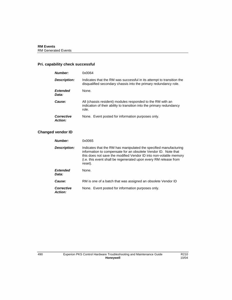
RM EventsRM Generated Events
490 Experion PKS Control Hardware Troubleshooting and Maintenance Guide R210Honeywell 10/04
Pri. capability check successful
Number: 0x0064
Description: Indicates that the RM was successful in its attempt to transition thedisqualified secondary chassis into the primary redundancy role.
ExtendedData:
None.
Cause: All (chassis resident) modules responded to the RM with anindication of their ability to transition into the primary redundancyrole.
CorrectiveAction:
None. Event posted for information purposes only.
Changed vendor ID
Number: 0x0065
Description: Indicates that the RM has manipulated the specified manufacturinginformation to compensate for an obsolete Vendor ID. Note thatthis does not save the modified Vendor ID into non-volatile memory(i.e. this event shall be regenerated upon every RM release fromreset).
ExtendedData:
None.
Cause: RM is one of a batch that was assigned an obsolete Vendor ID
CorrectiveAction:
None. Event posted for information purposes only.
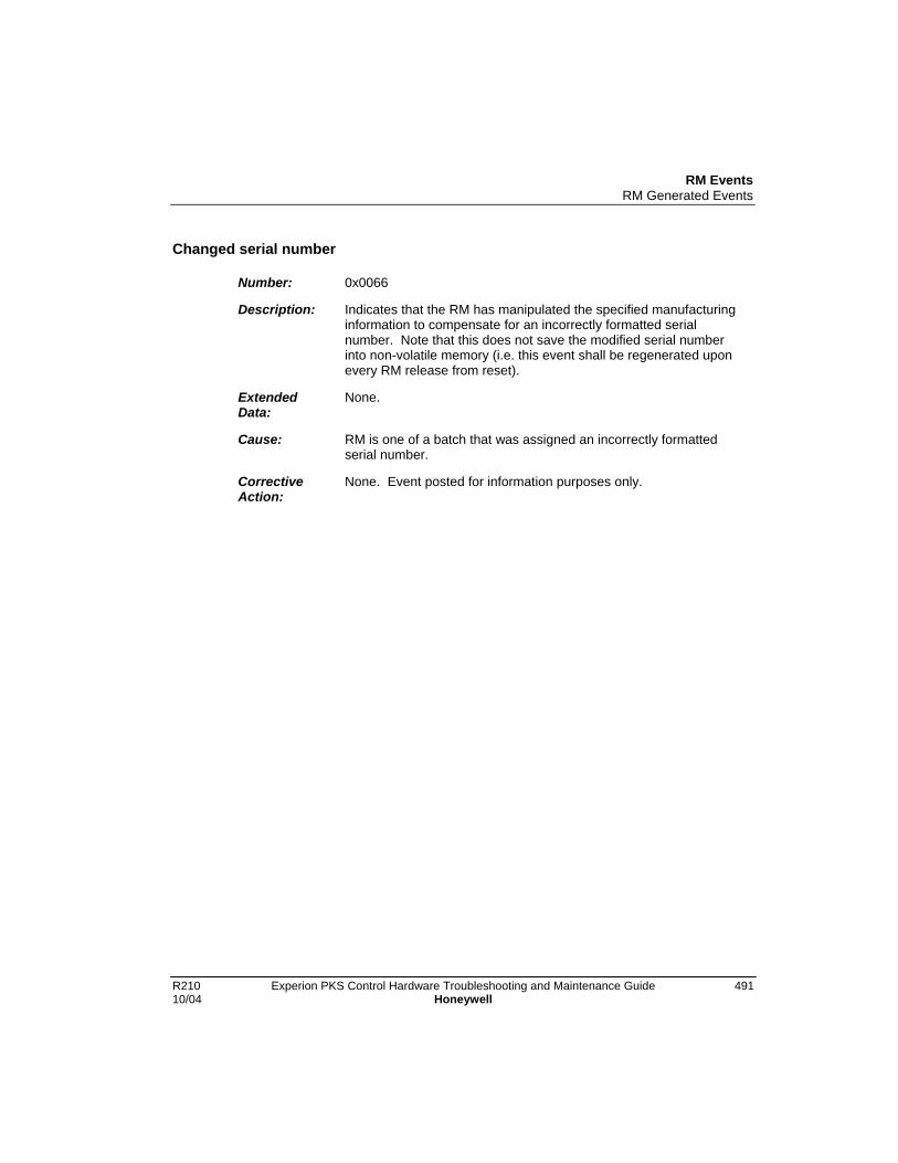
RM EventsRM Generated Events
R210 Experion PKS Control Hardware Troubleshooting and Maintenance Guide 49110/04 Honeywell
Changed serial number
Number: 0x0066
Description: Indicates that the RM has manipulated the specified manufacturinginformation to compensate for an incorrectly formatted serialnumber. Note that this does not save the modified serial numberinto non-volatile memory (i.e. this event shall be regenerated uponevery RM release from reset).
ExtendedData:
None.
Cause: RM is one of a batch that was assigned an incorrectly formattedserial number.
CorrectiveAction:
None. Event posted for information purposes only.

RM EventsRM Generated Events
492 Experion PKS Control Hardware Troubleshooting and Maintenance Guide R210Honeywell 10/04

R210 Experion PKS Control Hardware Troubleshooting and Maintenance Guide 49310/04 Honeywell
Test Sequence Numbers
CPMThe following table indicates the major tests performed during CPM startup, their testsequence numbers and their order of execution. These tests are basically a linearsequence, which uses very few subroutines and no stack. On any failure, the test loops atthat location so the problem can be easily diagnosed. Note that an abnormal conditionexists if the CPM remains in a particular test for more than 30 seconds at which time thespecified corrective action should be performed.
Table of CPM Test Sequence Numbers
TSN Description CorrectiveAction
0 Alphanumeric Display Test. The alphanumeric displayis a write-only device. As such, it is very difficult to testautomatically. However, diagnostics scroll vertical andhorizontal lines and vary brightness when all segmentsare lit. In this way an interested user can ascertainwhether the display as a whole or any particularsegment are functioning properly. Note that this testsequence number is not actually displayed. Thefirmware version is briefly displayed after this test (e.g.‘FW E’).
Replace the CPMCPM_CA06.
1 CPU Type & Version Check. This test is used to detecta bad, obsolete, or unexpected new CPU. The CPUchip version is briefly displayed after this test (e.g.E40+).
Replace the CPMCPM_CA06.
10 Flash ROM parity scan. For each ROM line (8 bytes) ofthe 1MB Boot Image area, the data is read and theexpected parity is computed and compared with theactual parity. The test is timed.
Replace the CPMCPM_CA06.
11 Flash ROM parity scan time. The time needed toperform the above test is checked for reasonability.This test detects CPU Instruction Cache failure and/orROM wait state problems.
Replace the CPMCPM_CA06.
12 The checksum of the Boot personality is computed andverified.
Replace the CPMCPM_CA06.
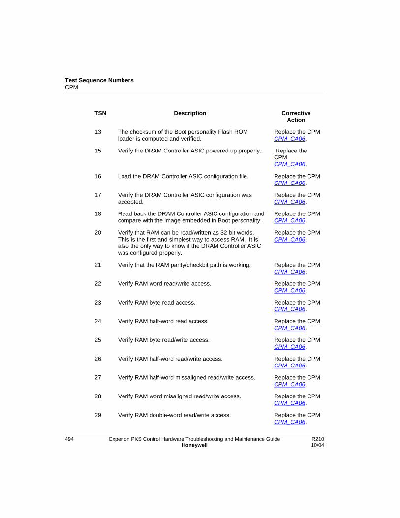
Test Sequence NumbersCPM
494 Experion PKS Control Hardware Troubleshooting and Maintenance Guide R210Honeywell 10/04
TSN Description CorrectiveAction
13 The checksum of the Boot personality Flash ROMloader is computed and verified.
Replace the CPMCPM_CA06.
15 Verify the DRAM Controller ASIC powered up properly. Replace theCPMCPM_CA06.
16 Load the DRAM Controller ASIC configuration file. Replace the CPMCPM_CA06.
17 Verify the DRAM Controller ASIC configuration wasaccepted.
Replace the CPMCPM_CA06.
18 Read back the DRAM Controller ASIC configuration andcompare with the image embedded in Boot personality.
Replace the CPMCPM_CA06.
20 Verify that RAM can be read/written as 32-bit words.This is the first and simplest way to access RAM. It isalso the only way to know if the DRAM Controller ASICwas configured properly.
Replace the CPMCPM_CA06.
21 Verify that the RAM parity/checkbit path is working. Replace the CPMCPM_CA06.
22 Verify RAM word read/write access. Replace the CPMCPM_CA06.
23 Verify RAM byte read access. Replace the CPMCPM_CA06.
24 Verify RAM half-word read access. Replace the CPMCPM_CA06.
25 Verify RAM byte read/write access. Replace the CPMCPM_CA06.
26 Verify RAM half-word read/write access. Replace the CPMCPM_CA06.
27 Verify RAM half-word missaligned read/write access. Replace the CPMCPM_CA06.
28 Verify RAM word misaligned read/write access. Replace the CPMCPM_CA06.
29 Verify RAM double-word read/write access. Replace the CPMCPM_CA06.
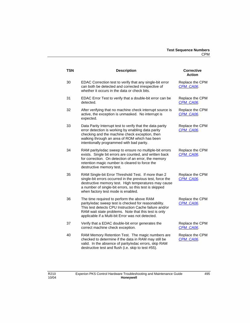
Test Sequence NumbersCPM
R210 Experion PKS Control Hardware Troubleshooting and Maintenance Guide 49510/04 Honeywell
TSN Description CorrectiveAction
30 EDAC Correction test to verify that any single-bit errorcan both be detected and corrected irrespective ofwhether it occurs in the data or check bits.
Replace the CPMCPM_CA06.
31 EDAC Error Test to verify that a double-bit error can bedetected.
Replace the CPMCPM_CA06.
32 After verifying that no machine check interrupt source isactive, the exception is unmasked. No interrupt isexpected.
Replace the CPMCPM_CA06.
33 Data Parity Interrupt test to verify that the data parityerror detection is working by enabling data paritychecking and the machine check exception, thenwalking through an area of ROM which has beenintentionally programmed with bad parity.
Replace the CPMCPM_CA06.
34 RAM parity/edac sweep to ensure no multiple-bit errorsexists. Single bit errors are counted, and written backfor correction. On detection of an error, the memoryretention magic number is cleared to force thedestructive memory test.
Replace the CPMCPM_CA06.
35 RAM Single-bit Error Threshold Test. If more than 2single-bit errors occurred in the previous test, force thedestructive memory test. High temperatures may causea number of single-bit errors, so this test is skippedwhen factory test mode is enabled.
Replace the CPMCPM_CA06.
36 The time required to perform the above RAMparity/edac sweep test is checked for reasonability.This test detects CPU Instruction Cache failure and/orRAM wait state problems. Note that this test is onlyapplicable if a Multi-bit Error was not detected.
Replace the CPMCPM_CA06.
37 Verify that a EDAC double-bit error generates thecorrect machine check exception.
Replace the CPMCPM_CA06.
40 RAM Memory Retention Test. The magic numbers arechecked to determine if the data in RAM may still bevalid. In the absence of parity/edac errors, skip RAMdestructive test and flush (i.e. skip to test #55).
Replace the CPMCPM_CA06.
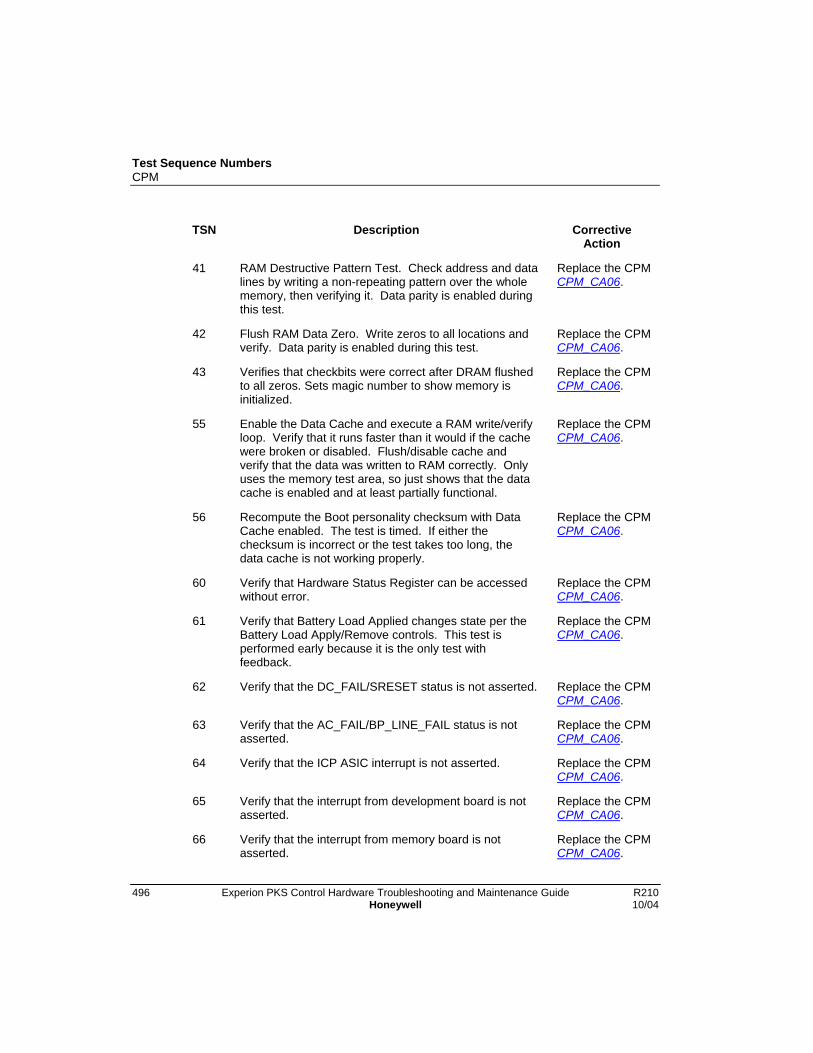
Test Sequence NumbersCPM
496 Experion PKS Control Hardware Troubleshooting and Maintenance Guide R210Honeywell 10/04
TSN Description CorrectiveAction
41 RAM Destructive Pattern Test. Check address and datalines by writing a non-repeating pattern over the wholememory, then verifying it. Data parity is enabled duringthis test.
Replace the CPMCPM_CA06.
42 Flush RAM Data Zero. Write zeros to all locations andverify. Data parity is enabled during this test.
Replace the CPMCPM_CA06.
43 Verifies that checkbits were correct after DRAM flushedto all zeros. Sets magic number to show memory isinitialized.
Replace the CPMCPM_CA06.
55 Enable the Data Cache and execute a RAM write/verifyloop. Verify that it runs faster than it would if the cachewere broken or disabled. Flush/disable cache andverify that the data was written to RAM correctly. Onlyuses the memory test area, so just shows that the datacache is enabled and at least partially functional.
Replace the CPMCPM_CA06.
56 Recompute the Boot personality checksum with DataCache enabled. The test is timed. If either thechecksum is incorrect or the test takes too long, thedata cache is not working properly.
Replace the CPMCPM_CA06.
60 Verify that Hardware Status Register can be accessedwithout error.
Replace the CPMCPM_CA06.
61 Verify that Battery Load Applied changes state per theBattery Load Apply/Remove controls. This test isperformed early because it is the only test withfeedback.
Replace the CPMCPM_CA06.
62 Verify that the DC_FAIL/SRESET status is not asserted. Replace the CPMCPM_CA06.
63 Verify that the AC_FAIL/BP_LINE_FAIL status is notasserted.
Replace the CPMCPM_CA06.
64 Verify that the ICP ASIC interrupt is not asserted. Replace the CPMCPM_CA06.
65 Verify that the interrupt from development board is notasserted.
Replace the CPMCPM_CA06.
66 Verify that the interrupt from memory board is notasserted.
Replace the CPMCPM_CA06.

Test Sequence NumbersCPM
R210 Experion PKS Control Hardware Troubleshooting and Maintenance Guide 49710/04 Honeywell
TSN Description CorrectiveAction
67 If factory test mode is enabled, verify that the SYS_FAILstatus is not asserted for longer than a finite period, toaccount for other module’s tests.
Replace the CPMCPM_CA06.
68 Verify that Watchdog Timer Timeout status is notasserted.
Replace the CPMCPM_CA06.
70 Verify that the ICP_FAULT status is not asserted. Thiswould indicate that the ICP ASIC had failed to come outof reset.
Replace the CPMCPM_CA06.
71 ICP ASIC Release and Stuck Interrupt Test. Enablesinterrupts to make sure that there is no interrupt stuck inthe asserted state.
Replace the CPMCPM_CA06.
72 If factory test mode is enabled, verify that systemcontrols assert and deassert the SYSFAIL_L condition.Uses timeouts to prevent conflicts with other modulesunder test on the same backplane. No SYSFAIL_Linterrupt test. This test fails if another module leavesSYSFAIL_L asserted.
Replace the CPMCPM_CA06.
73 Watchdog Timer Test. Verify that the WDT does notexpire when refreshed over a period of 500 msec. Usesthe WDT Test mode to verify that the WDT is capable ofinterrupt generation on timeout within a fininte expectedtime range.
Replace the CPMCPM_CA06.
100 ICP Shared RAM Destructive Pattern Test. Checkaddress and data lines by writing a non-repeatingpattern over the whole memory, then verifying it.
Replace the CPMCPM_CA06.
102 ICP Shared RAM Initialization. Replace the CPMCPM_CA06.
111 ICP ASIC Register Access Test. Replace the CPMCPM_CA06.
112 ICP ASIC Unique Address Echo Test. Correct accessto the ICP Shared RAM from the ICP ASIC is verifiedthrough the Echo Test, by asking the ASIC to write eachlocation’s address at that address. This test isperformed once for the address and once for thecomplement of the address.
Replace the CPMCPM_CA06.

Test Sequence NumbersCPM
498 Experion PKS Control Hardware Troubleshooting and Maintenance Guide R210Honeywell 10/04
TSN Description CorrectiveAction
113 Verify that the ICP ASIC can be locked out of ICPShared RAM.
Replace the CPMCPM_CA06.
114 ICP Clock test to compare the ICP ASIC clock againstthe CPU clock to make sure they are running at thesame relative rates.
Replace the CPMCPM_CA06.
116 ICP ASIC Interrupt Test. Replace the CPMCPM_CA06.
120 Synchronization Hardware (i.e. Tracker mechanism)test to ensure the controller redundancy specifichardware works as expected.
Replace the CPMCPM_CA06.
130 Perform Application personality parity/edac scan. Replace the CPMCPM_CA06.
131 Erase the Application personality if the previous testindicated a parity/edac error.
Replace the CPMCPM_CA06.
132 Perform parity/edac scan on the Application personalityarea, which has been erased.
Replace the CPMCPM_CA06.
133 Compute CPM Application personality checksum andcompare with embedded value. A key is written in RAMto indicate whether the personality is invalid or validdepending on whether a checksum error was detectedor not respectively. In other words, checksum errordetection forces the CPM to execute its Bootpersonality.
N/A
255 The CPM has completed startup diagnostics. TheAlphanumeric Display is updated to display either PASSwhen starting the operating system in the Boot firmwareor BOOT when starting the operating system in theApplication firmware.
Replace the CPMCPM_CA06.
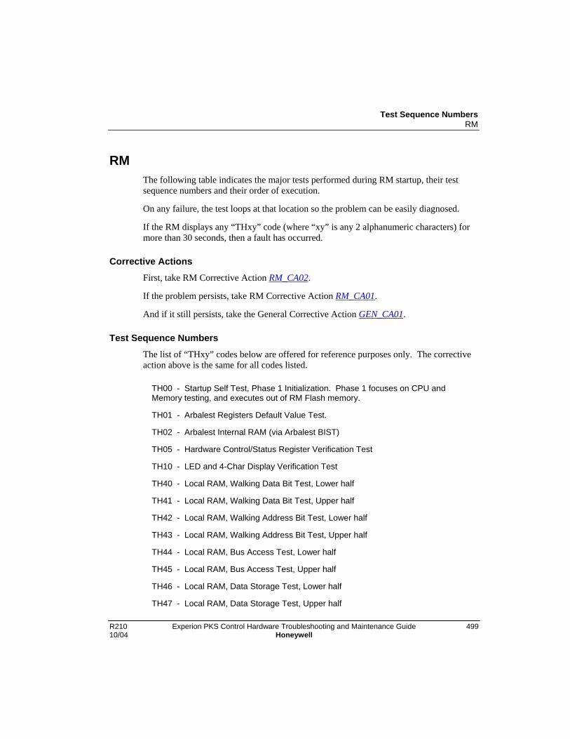
Test Sequence NumbersRM
R210 Experion PKS Control Hardware Troubleshooting and Maintenance Guide 49910/04 Honeywell
RMThe following table indicates the major tests performed during RM startup, their testsequence numbers and their order of execution.
On any failure, the test loops at that location so the problem can be easily diagnosed.
If the RM displays any “THxy” code (where “xy” is any 2 alphanumeric characters) formore than 30 seconds, then a fault has occurred.
Corrective ActionsFirst, take RM Corrective Action RM_CA02.
If the problem persists, take RM Corrective Action RM_CA01.
And if it still persists, take the General Corrective Action GEN_CA01.
Test Sequence Numbers
The list of “THxy” codes below are offered for reference purposes only. The correctiveaction above is the same for all codes listed.
TH00 - Startup Self Test, Phase 1 Initialization. Phase 1 focuses on CPU andMemory testing, and executes out of RM Flash memory.
TH01 - Arbalest Registers Default Value Test.
TH02 - Arbalest Internal RAM (via Arbalest BIST)
TH05 - Hardware Control/Status Register Verification Test
TH10 - LED and 4-Char Display Verification Test
TH40 - Local RAM, Walking Data Bit Test, Lower half
TH41 - Local RAM, Walking Data Bit Test, Upper half
TH42 - Local RAM, Walking Address Bit Test, Lower half
TH43 - Local RAM, Walking Address Bit Test, Upper half
TH44 - Local RAM, Bus Access Test, Lower half
TH45 - Local RAM, Bus Access Test, Upper half
TH46 - Local RAM, Data Storage Test, Lower half
TH47 - Local RAM, Data Storage Test, Upper half
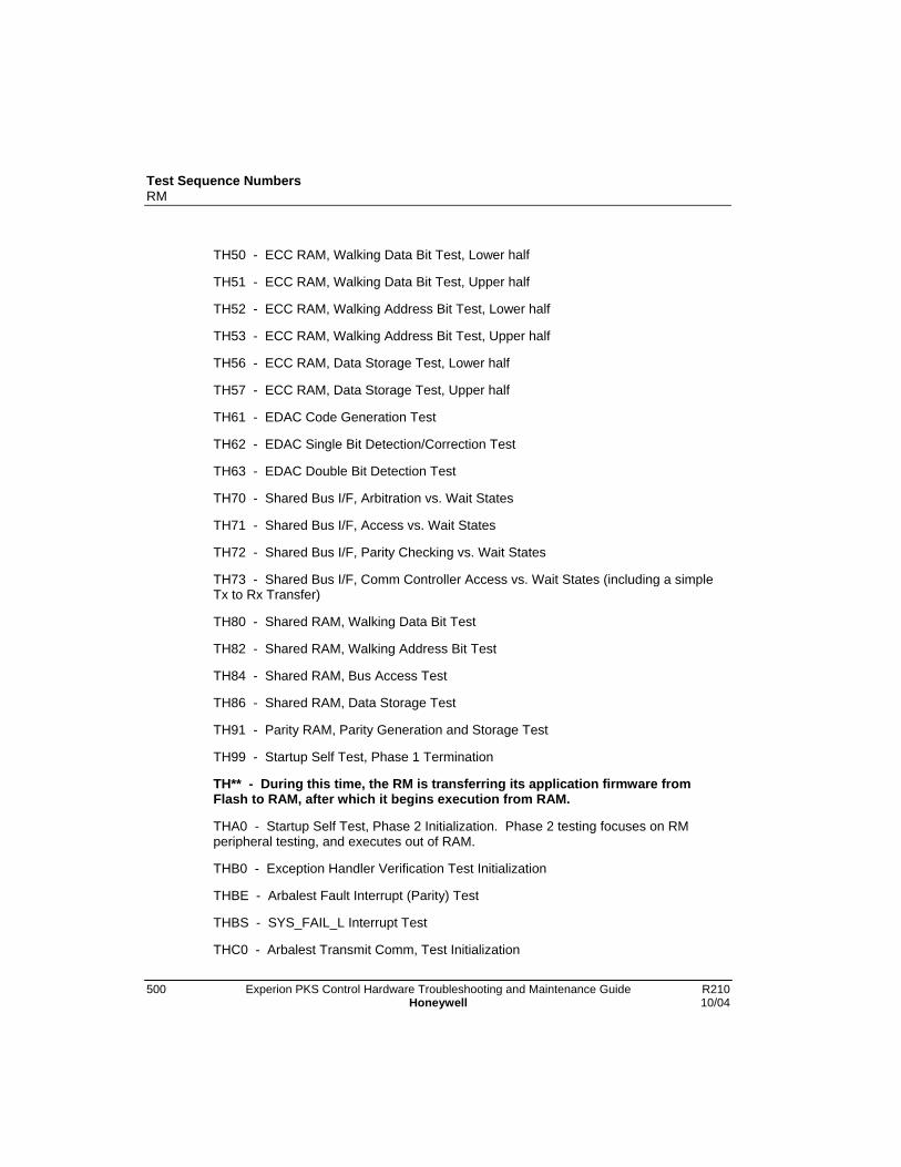
Test Sequence NumbersRM
500 Experion PKS Control Hardware Troubleshooting and Maintenance Guide R210Honeywell 10/04
TH50 - ECC RAM, Walking Data Bit Test, Lower half
TH51 - ECC RAM, Walking Data Bit Test, Upper half
TH52 - ECC RAM, Walking Address Bit Test, Lower half
TH53 - ECC RAM, Walking Address Bit Test, Upper half
TH56 - ECC RAM, Data Storage Test, Lower half
TH57 - ECC RAM, Data Storage Test, Upper half
TH61 - EDAC Code Generation Test
TH62 - EDAC Single Bit Detection/Correction Test
TH63 - EDAC Double Bit Detection Test
TH70 - Shared Bus I/F, Arbitration vs. Wait States
TH71 - Shared Bus I/F, Access vs. Wait States
TH72 - Shared Bus I/F, Parity Checking vs. Wait States
TH73 - Shared Bus I/F, Comm Controller Access vs. Wait States (including a simpleTx to Rx Transfer)
TH80 - Shared RAM, Walking Data Bit Test
TH82 - Shared RAM, Walking Address Bit Test
TH84 - Shared RAM, Bus Access Test
TH86 - Shared RAM, Data Storage Test
TH91 - Parity RAM, Parity Generation and Storage Test
TH99 - Startup Self Test, Phase 1 Termination
TH** - During this time, the RM is transferring its application firmware fromFlash to RAM, after which it begins execution from RAM.
THA0 - Startup Self Test, Phase 2 Initialization. Phase 2 testing focuses on RMperipheral testing, and executes out of RAM.
THB0 - Exception Handler Verification Test Initialization
THBE - Arbalest Fault Interrupt (Parity) Test
THBS - SYS_FAIL_L Interrupt Test
THC0 - Arbalest Transmit Comm, Test Initialization

Test Sequence NumbersRM
R210 Experion PKS Control Hardware Troubleshooting and Maintenance Guide 50110/04 Honeywell
THCA - Arbalest Transmit Comm, Tx Queue Pattern Test
THCB - Arbalest Transmit Comm, Tx Queue Index/Count Test
THCC - Arbalest Transmit Comm, Tx Descriptor ID Port Test
THCH - Arbalest Transmit Comm, Receive ID Queue Test
THCJ - Arbalest Transmit Comm, Rx Queue Index/Count Test
THCK - Arbalest Transmit Comm, Rx Descriptor ID Port Test
THDA - Arbalest Transmit Comm, Local RAM TX Descriptor Processing Test
THDB - Arbalest Transmit Comm, Illegal Descriptor ID Test
THDC - Arbalest Transmit Comm, Bogus Descriptor Address Test
THDD - Arbalest Transmit Comm, Invalid Descriptor Type Test
THDE - Arbalest Transmit Comm, Invalid Destination ID Test
THDF - Arbalest Transmit Comm, Bogus Buffer Address Test
THDG - Arbalest Transmit Comm, Lookup Table Double-Bit Error Test
THDH - Arbalest Transmit Comm, Tx Descriptor Double-Bit Error Test
THDJ - Arbalest Transmit Comm, Tx Lookup Table/Descriptor Single-Bit Error Tests
THDK - Arbalest Transmit Comm, Word and Packet Count Verification
THEA - Arbalest Transmit Comm, Tx Shared Bus Descriptor Tests, Initialization
THEB - Arbalest Transmit Comm, SB Tx Descriptor Processing Tests
THEC - Arbalest Transmit Comm, Bogus Descriptor Address Test
THED - Arbalest Transmit Comm, Invalid Descriptor Type Test
THEE - Arbalest Transmit Comm, Invalid Destination Id Test
THEF - Arbalest Transmit Comm, Bogus Buffer Address Test
THEG - Arbalest Transmit Comm, Lookup Table Parity Error Test
THEH - Arbalest Transmit Comm, Tx Descriptor Parity Error Test
THEJ - Arbalest Transmit Comm, Tx Descriptor Shared Bus Access Test
THEK - Arbalest Transmit Comm, Word And Packet Count Verification Test
THFA - Arbalest Transmit Comm, Local Bus Buffer Access Tests, Initialization
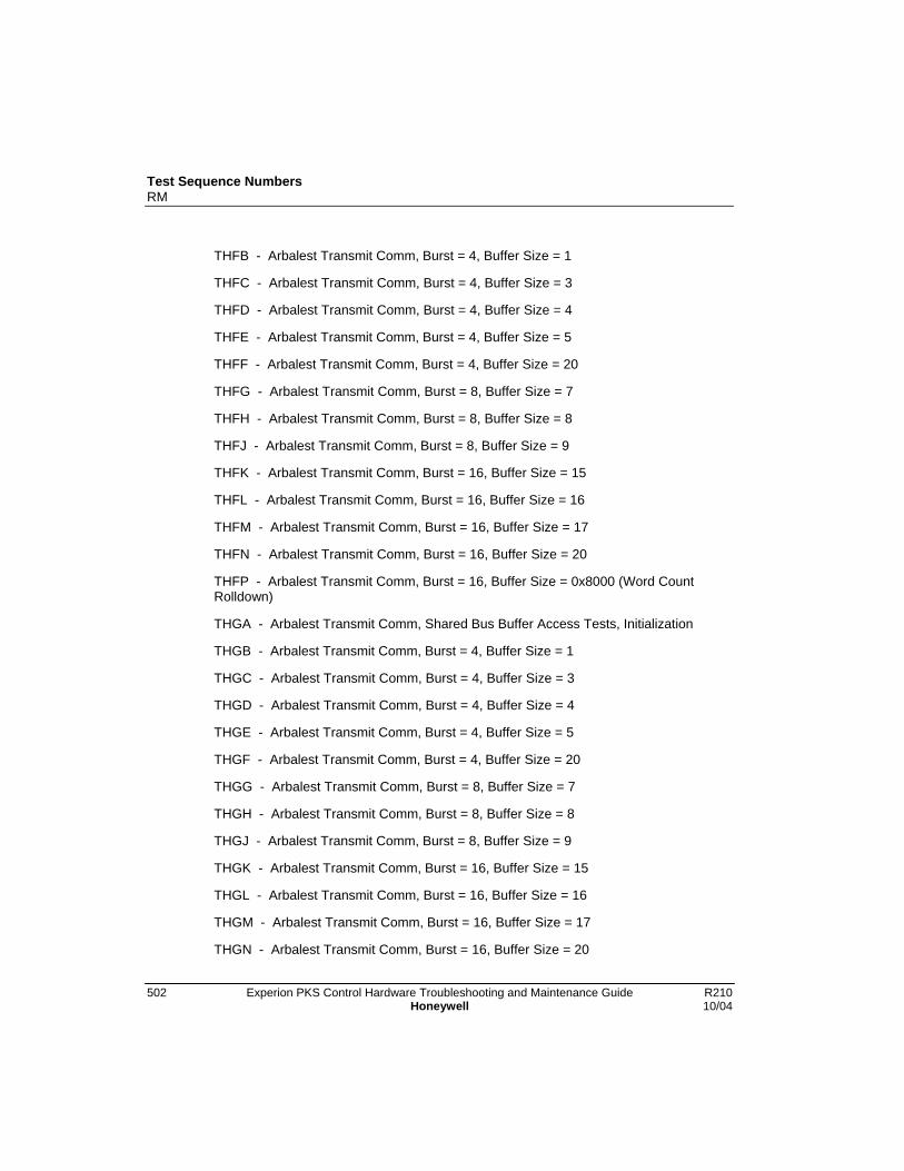
Test Sequence NumbersRM
502 Experion PKS Control Hardware Troubleshooting and Maintenance Guide R210Honeywell 10/04
THFB - Arbalest Transmit Comm, Burst = 4, Buffer Size = 1
THFC - Arbalest Transmit Comm, Burst = 4, Buffer Size = 3
THFD - Arbalest Transmit Comm, Burst = 4, Buffer Size = 4
THFE - Arbalest Transmit Comm, Burst = 4, Buffer Size = 5
THFF - Arbalest Transmit Comm, Burst = 4, Buffer Size = 20
THFG - Arbalest Transmit Comm, Burst = 8, Buffer Size = 7
THFH - Arbalest Transmit Comm, Burst = 8, Buffer Size = 8
THFJ - Arbalest Transmit Comm, Burst = 8, Buffer Size = 9
THFK - Arbalest Transmit Comm, Burst = 16, Buffer Size = 15
THFL - Arbalest Transmit Comm, Burst = 16, Buffer Size = 16
THFM - Arbalest Transmit Comm, Burst = 16, Buffer Size = 17
THFN - Arbalest Transmit Comm, Burst = 16, Buffer Size = 20
THFP - Arbalest Transmit Comm, Burst = 16, Buffer Size = 0x8000 (Word CountRolldown)
THGA - Arbalest Transmit Comm, Shared Bus Buffer Access Tests, Initialization
THGB - Arbalest Transmit Comm, Burst = 4, Buffer Size = 1
THGC - Arbalest Transmit Comm, Burst = 4, Buffer Size = 3
THGD - Arbalest Transmit Comm, Burst = 4, Buffer Size = 4
THGE - Arbalest Transmit Comm, Burst = 4, Buffer Size = 5
THGF - Arbalest Transmit Comm, Burst = 4, Buffer Size = 20
THGG - Arbalest Transmit Comm, Burst = 8, Buffer Size = 7
THGH - Arbalest Transmit Comm, Burst = 8, Buffer Size = 8
THGJ - Arbalest Transmit Comm, Burst = 8, Buffer Size = 9
THGK - Arbalest Transmit Comm, Burst = 16, Buffer Size = 15
THGL - Arbalest Transmit Comm, Burst = 16, Buffer Size = 16
THGM - Arbalest Transmit Comm, Burst = 16, Buffer Size = 17
THGN - Arbalest Transmit Comm, Burst = 16, Buffer Size = 20
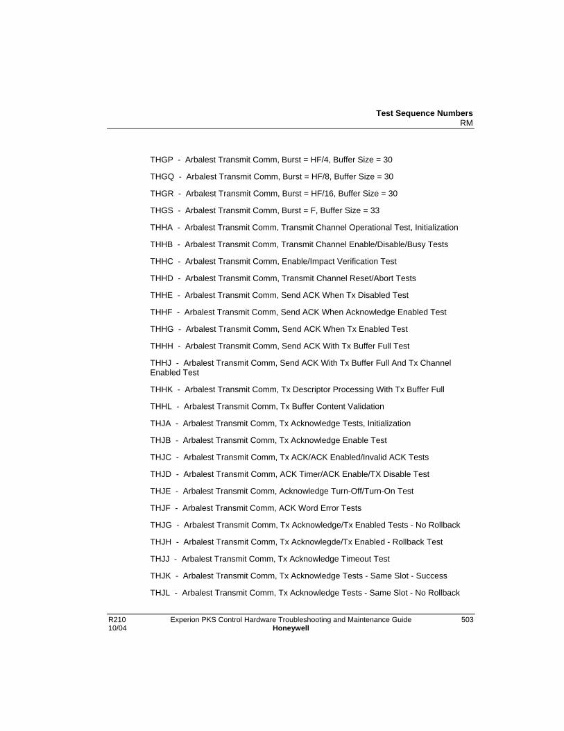
Test Sequence NumbersRM
R210 Experion PKS Control Hardware Troubleshooting and Maintenance Guide 50310/04 Honeywell
THGP - Arbalest Transmit Comm, Burst = HF/4, Buffer Size = 30
THGQ - Arbalest Transmit Comm, Burst = HF/8, Buffer Size = 30
THGR - Arbalest Transmit Comm, Burst = HF/16, Buffer Size = 30
THGS - Arbalest Transmit Comm, Burst = F, Buffer Size = 33
THHA - Arbalest Transmit Comm, Transmit Channel Operational Test, Initialization
THHB - Arbalest Transmit Comm, Transmit Channel Enable/Disable/Busy Tests
THHC - Arbalest Transmit Comm, Enable/Impact Verification Test
THHD - Arbalest Transmit Comm, Transmit Channel Reset/Abort Tests
THHE - Arbalest Transmit Comm, Send ACK When Tx Disabled Test
THHF - Arbalest Transmit Comm, Send ACK When Acknowledge Enabled Test
THHG - Arbalest Transmit Comm, Send ACK When Tx Enabled Test
THHH - Arbalest Transmit Comm, Send ACK With Tx Buffer Full Test
THHJ - Arbalest Transmit Comm, Send ACK With Tx Buffer Full And Tx ChannelEnabled Test
THHK - Arbalest Transmit Comm, Tx Descriptor Processing With Tx Buffer Full
THHL - Arbalest Transmit Comm, Tx Buffer Content Validation
THJA - Arbalest Transmit Comm, Tx Acknowledge Tests, Initialization
THJB - Arbalest Transmit Comm, Tx Acknowledge Enable Test
THJC - Arbalest Transmit Comm, Tx ACK/ACK Enabled/Invalid ACK Tests
THJD - Arbalest Transmit Comm, ACK Timer/ACK Enable/TX Disable Test
THJE - Arbalest Transmit Comm, Acknowledge Turn-Off/Turn-On Test
THJF - Arbalest Transmit Comm, ACK Word Error Tests
THJG - Arbalest Transmit Comm, Tx Acknowledge/Tx Enabled Tests - No Rollback
THJH - Arbalest Transmit Comm, Tx Acknowlegde/Tx Enabled - Rollback Test
THJJ - Arbalest Transmit Comm, Tx Acknowledge Timeout Test
THJK - Arbalest Transmit Comm, Tx Acknowledge Tests - Same Slot - Success
THJL - Arbalest Transmit Comm, Tx Acknowledge Tests - Same Slot - No Rollback
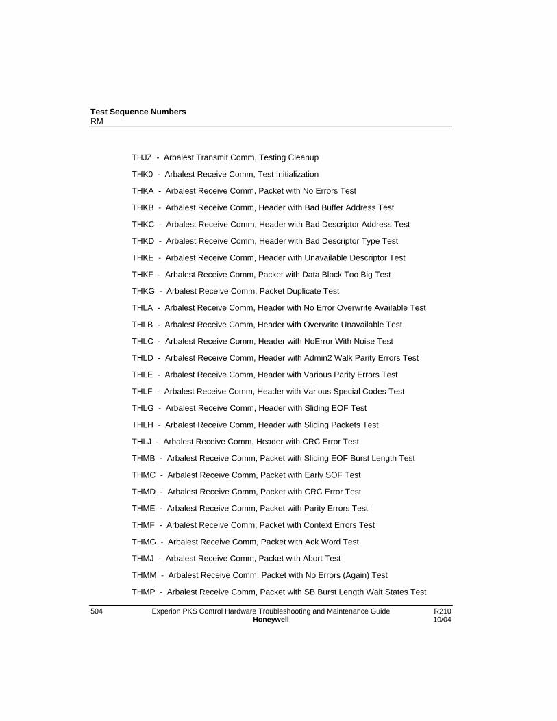
Test Sequence NumbersRM
504 Experion PKS Control Hardware Troubleshooting and Maintenance Guide R210Honeywell 10/04
THJZ - Arbalest Transmit Comm, Testing Cleanup
THK0 - Arbalest Receive Comm, Test Initialization
THKA - Arbalest Receive Comm, Packet with No Errors Test
THKB - Arbalest Receive Comm, Header with Bad Buffer Address Test
THKC - Arbalest Receive Comm, Header with Bad Descriptor Address Test
THKD - Arbalest Receive Comm, Header with Bad Descriptor Type Test
THKE - Arbalest Receive Comm, Header with Unavailable Descriptor Test
THKF - Arbalest Receive Comm, Packet with Data Block Too Big Test
THKG - Arbalest Receive Comm, Packet Duplicate Test
THLA - Arbalest Receive Comm, Header with No Error Overwrite Available Test
THLB - Arbalest Receive Comm, Header with Overwrite Unavailable Test
THLC - Arbalest Receive Comm, Header with NoError With Noise Test
THLD - Arbalest Receive Comm, Header with Admin2 Walk Parity Errors Test
THLE - Arbalest Receive Comm, Header with Various Parity Errors Test
THLF - Arbalest Receive Comm, Header with Various Special Codes Test
THLG - Arbalest Receive Comm, Header with Sliding EOF Test
THLH - Arbalest Receive Comm, Header with Sliding Packets Test
THLJ - Arbalest Receive Comm, Header with CRC Error Test
THMB - Arbalest Receive Comm, Packet with Sliding EOF Burst Length Test
THMC - Arbalest Receive Comm, Packet with Early SOF Test
THMD - Arbalest Receive Comm, Packet with CRC Error Test
THME - Arbalest Receive Comm, Packet with Parity Errors Test
THMF - Arbalest Receive Comm, Packet with Context Errors Test
THMG - Arbalest Receive Comm, Packet with Ack Word Test
THMJ - Arbalest Receive Comm, Packet with Abort Test
THMM - Arbalest Receive Comm, Packet with No Errors (Again) Test
THMP - Arbalest Receive Comm, Packet with SB Burst Length Wait States Test

Test Sequence NumbersRM
R210 Experion PKS Control Hardware Troubleshooting and Maintenance Guide 50510/04 Honeywell
THMZ - Arbalest Receive Comm, Testing Cleanup
THP0 - Arbalest HotLink I/F, Tx Bfr Test, Test Initialization
THPA - Arbalest HotLink I/F, Tx Bfr Test, Empty Flag Test
THPB - Arbalest HotLink I/F, Tx Bfr Test, Half-Full Flag Test
THPC - Arbalest HotLink I/F, Tx Bfr Test, Full Flag Test
THPD - Arbalest HotLink I/F, Tx Bfr Test, Walking Ones/Zeros Test
THQA - Arbalest HotLink I/F, Rx Bfr Test, Empty Flag Test
THQB - Arbalest HotLink I/F, Rx Bfr Test, Half-Full Flag Test
THQC - Arbalest HotLink I/F, Rx Bfr Test, Full Flag Test
THQD - Arbalest HotLink I/F, Rx Bfr Test, Walking Ones/Zeros Test
THRA - Arbalest HotLink I/F, Tx/Rx Test, Transmit Buffer Clear Tes
THRB - Arbalest HotLink I/F, Tx/Rx Test, Receive Buffer Clear Test
THRC - Arbalest HotLink I/F, Tx/Rx Test, Transmit Interface Enable/Disable Test
THRE - Arbalest HotLink I/F, Tx/Rx Test, Receive Interface Enable/Disable Test
THRF - Arbalest HotLink I/F, Tx/Rx Test, Transmit/Receive Data Transfer Test
THSA - Arbalest HotLink I/F, HOTLink BIST
THSZ - Arbalest HotLink I/F, Testing Cleanup
THZZ - Phase 2 Cleanup. End of RM Startup Self Testing.
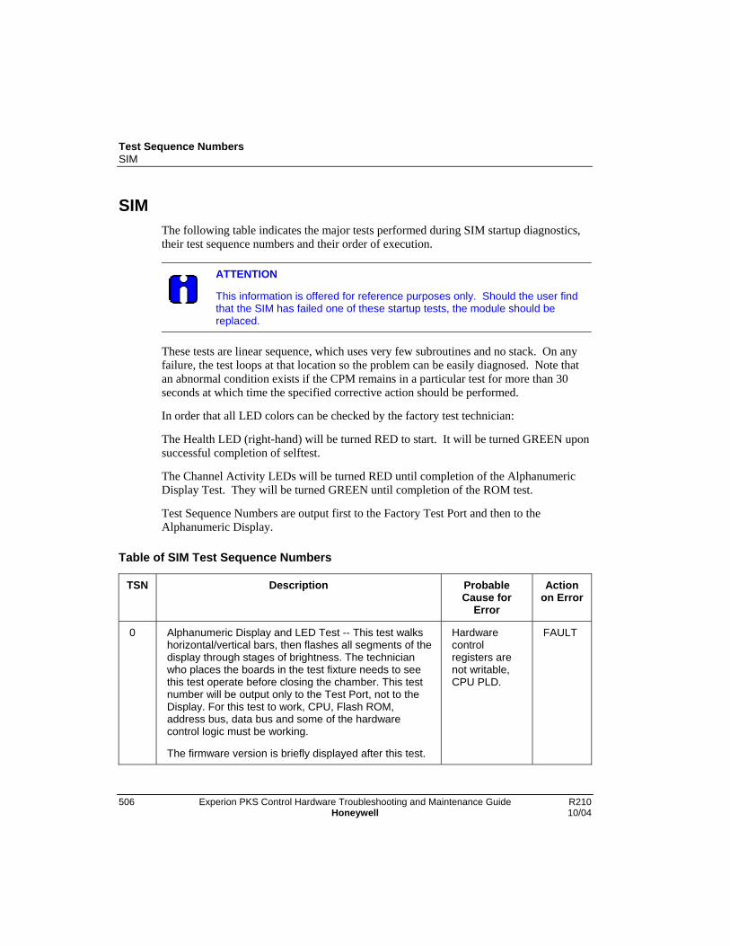
Test Sequence NumbersSIM
506 Experion PKS Control Hardware Troubleshooting and Maintenance Guide R210Honeywell 10/04
SIMThe following table indicates the major tests performed during SIM startup diagnostics,their test sequence numbers and their order of execution.
ATTENTION
This information is offered for reference purposes only. Should the user findthat the SIM has failed one of these startup tests, the module should bereplaced.
These tests are linear sequence, which uses very few subroutines and no stack. On anyfailure, the test loops at that location so the problem can be easily diagnosed. Note thatan abnormal condition exists if the CPM remains in a particular test for more than 30seconds at which time the specified corrective action should be performed.
In order that all LED colors can be checked by the factory test technician:
The Health LED (right-hand) will be turned RED to start. It will be turned GREEN uponsuccessful completion of selftest.
The Channel Activity LEDs will be turned RED until completion of the AlphanumericDisplay Test. They will be turned GREEN until completion of the ROM test.
Test Sequence Numbers are output first to the Factory Test Port and then to theAlphanumeric Display.
Table of SIM Test Sequence Numbers
TSN Description ProbableCause for
Error
Actionon Error
0 Alphanumeric Display and LED Test -- This test walkshorizontal/vertical bars, then flashes all segments of thedisplay through stages of brightness. The technicianwho places the boards in the test fixture needs to seethis test operate before closing the chamber. This testnumber will be output only to the Test Port, not to theDisplay. For this test to work, CPU, Flash ROM,address bus, data bus and some of the hardwarecontrol logic must be working.
The firmware version is briefly displayed after this test.
Hardwarecontrolregisters arenot writable,CPU PLD.
FAULT
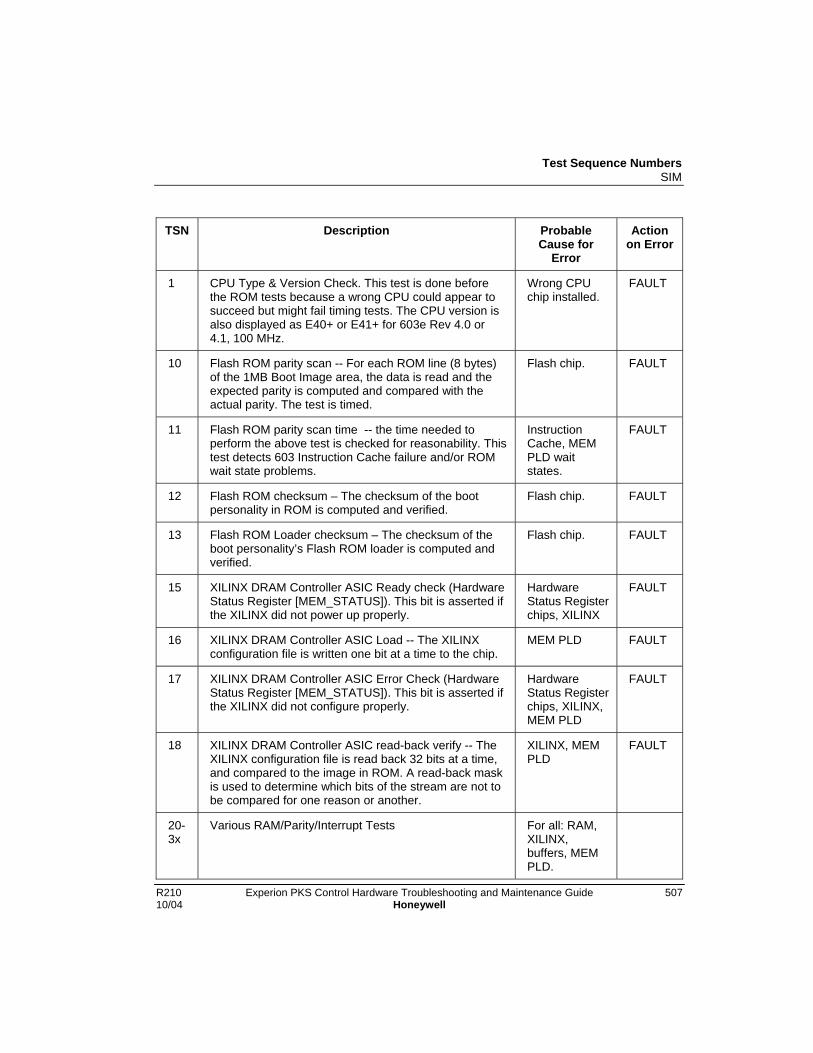
Test Sequence NumbersSIM
R210 Experion PKS Control Hardware Troubleshooting and Maintenance Guide 50710/04 Honeywell
TSN Description ProbableCause for
Error
Actionon Error
1 CPU Type & Version Check. This test is done beforethe ROM tests because a wrong CPU could appear tosucceed but might fail timing tests. The CPU version isalso displayed as E40+ or E41+ for 603e Rev 4.0 or4.1, 100 MHz.
Wrong CPUchip installed.
FAULT
10 Flash ROM parity scan -- For each ROM line (8 bytes)of the 1MB Boot Image area, the data is read and theexpected parity is computed and compared with theactual parity. The test is timed.
Flash chip. FAULT
11 Flash ROM parity scan time -- the time needed toperform the above test is checked for reasonability. Thistest detects 603 Instruction Cache failure and/or ROMwait state problems.
InstructionCache, MEMPLD waitstates.
FAULT
12 Flash ROM checksum – The checksum of the bootpersonality in ROM is computed and verified.
Flash chip. FAULT
13 Flash ROM Loader checksum – The checksum of theboot personality’s Flash ROM loader is computed andverified.
Flash chip. FAULT
15 XILINX DRAM Controller ASIC Ready check (HardwareStatus Register [MEM_STATUS]). This bit is asserted ifthe XILINX did not power up properly.
HardwareStatus Registerchips, XILINX
FAULT
16 XILINX DRAM Controller ASIC Load -- The XILINXconfiguration file is written one bit at a time to the chip.
MEM PLD FAULT
17 XILINX DRAM Controller ASIC Error Check (HardwareStatus Register [MEM_STATUS]). This bit is asserted ifthe XILINX did not configure properly.
HardwareStatus Registerchips, XILINX,MEM PLD
FAULT
18 XILINX DRAM Controller ASIC read-back verify -- TheXILINX configuration file is read back 32 bits at a time,and compared to the image in ROM. A read-back maskis used to determine which bits of the stream are not tobe compared for one reason or another.
XILINX, MEMPLD
FAULT
20-3x
Various RAM/Parity/Interrupt Tests For all: RAM,XILINX,buffers, MEMPLD.

Test Sequence NumbersSIM
508 Experion PKS Control Hardware Troubleshooting and Maintenance Guide R210Honeywell 10/04
TSN Description ProbableCause for
Error
Actionon Error
20 RAM path – verifies that RAM can be read/written as32-bit words. This is the first and simplest way to accessRAM. It is also the only way to know if the XILINX wasconfigured properly.
FAULT
21 RAM parity path -- writes two 8-byte patterns andverifies that parity byte was set correctly, even and odd.
FAULT
22 RAM word access – verifies that word patterns can bewritten and read, including three cases of miss-alignedtransfer.
FAULT
23 RAM byte access – verifies that writing a string of 8bytes can be read back as 2 correct words, and as 8bytes.
FAULT
24 RAM half access – verifies that half words can be read. FAULT
25 RAM byte write – verifies that bytes can be writtencorrectly.
FAULT
26 RAM half write – verifies that half-words can be writtencorrectly.
FAULT
27 RAM half align – verifies that half-words can be writtenand ready when miss-aligned.
FAULT
28 RAM word align – verifies that words can be written andready when miss-aligned.
FAULT
29 RAM double access – verifies that the floating point unitcan write and read a double-word value, and the samevalue is correctly stored as two words.
FAULT
30 EDAC Correction – Verifies that any single-bit error canboth be detected and corrected, in data or check bits, inhigh or low word. One bit at a time is changed andwalked through one line of RAM.
FAULT
31 EDAC Error Test – verifies that a double-bit error can bedetected, in both high and low word.
FAULT
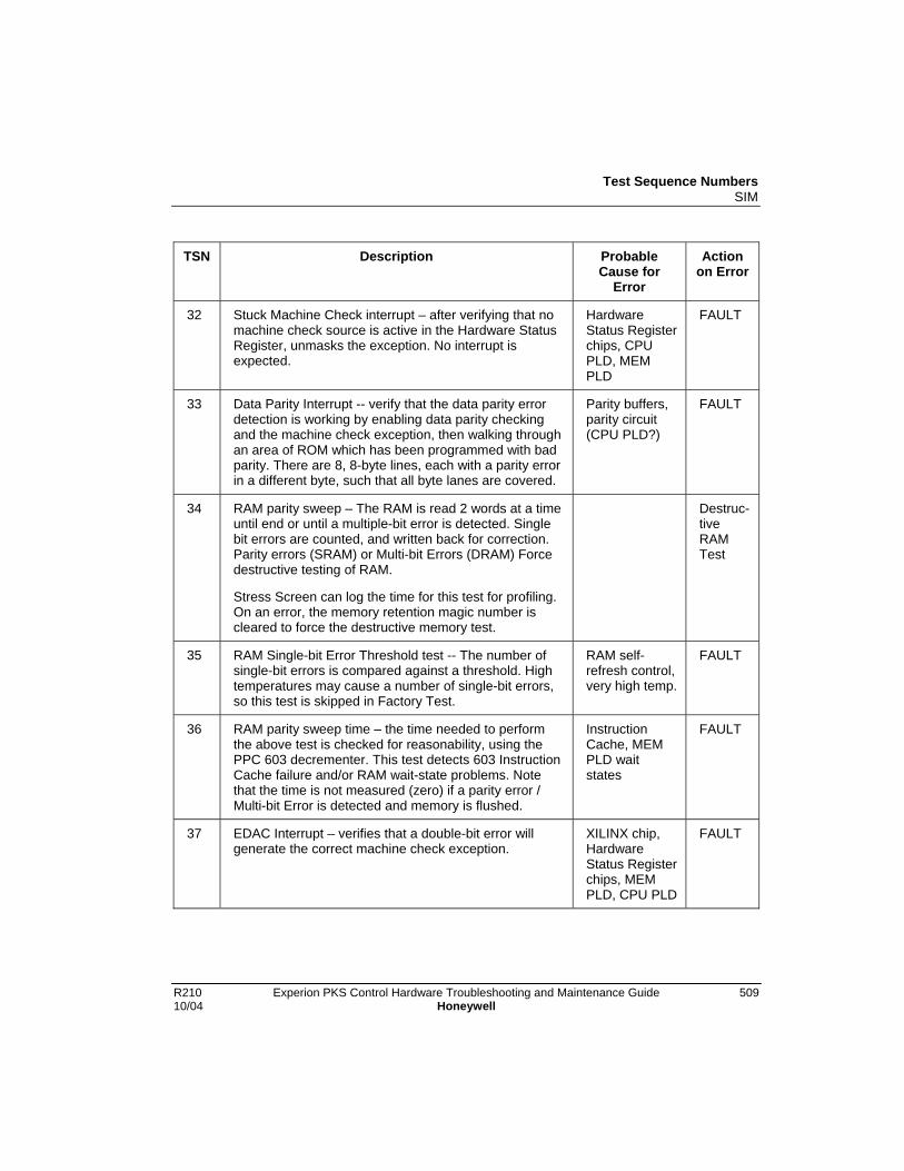
Test Sequence NumbersSIM
R210 Experion PKS Control Hardware Troubleshooting and Maintenance Guide 50910/04 Honeywell
TSN Description ProbableCause for
Error
Actionon Error
32 Stuck Machine Check interrupt – after verifying that nomachine check source is active in the Hardware StatusRegister, unmasks the exception. No interrupt isexpected.
HardwareStatus Registerchips, CPUPLD, MEMPLD
FAULT
33 Data Parity Interrupt -- verify that the data parity errordetection is working by enabling data parity checkingand the machine check exception, then walking throughan area of ROM which has been programmed with badparity. There are 8, 8-byte lines, each with a parity errorin a different byte, such that all byte lanes are covered.
Parity buffers,parity circuit(CPU PLD?)
FAULT
34 RAM parity sweep – The RAM is read 2 words at a timeuntil end or until a multiple-bit error is detected. Singlebit errors are counted, and written back for correction.Parity errors (SRAM) or Multi-bit Errors (DRAM) Forcedestructive testing of RAM.
Stress Screen can log the time for this test for profiling.On an error, the memory retention magic number iscleared to force the destructive memory test.
Destruc-tiveRAMTest
35 RAM Single-bit Error Threshold test -- The number ofsingle-bit errors is compared against a threshold. Hightemperatures may cause a number of single-bit errors,so this test is skipped in Factory Test.
RAM self-refresh control,very high temp.
FAULT
36 RAM parity sweep time – the time needed to performthe above test is checked for reasonability, using thePPC 603 decrementer. This test detects 603 InstructionCache failure and/or RAM wait-state problems. Notethat the time is not measured (zero) if a parity error /Multi-bit Error is detected and memory is flushed.
InstructionCache, MEMPLD waitstates
FAULT
37 EDAC Interrupt – verifies that a double-bit error willgenerate the correct machine check exception.
XILINX chip,HardwareStatus Registerchips, MEMPLD, CPU PLD
FAULT
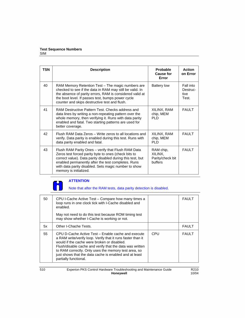
Test Sequence NumbersSIM
510 Experion PKS Control Hardware Troubleshooting and Maintenance Guide R210Honeywell 10/04
TSN Description ProbableCause for
Error
Actionon Error
40 RAM Memory Retention Test – The magic numbers arechecked to see if the data in RAM may still be valid. Inthe absence of parity errors, RAM is considered valid atthe boot level. If passes test, bumps power cyclecounter and skips destructive test and flush.
Battery low Fall intoDestruc-tiveTest.
41 RAM Destructive Pattern Test. Checks address anddata lines by writing a non-repeating pattern over thewhole memory, then verifying it. Runs with data parityenabled and fatal. Two starting patterns are used forbetter coverage.
XILINX, RAMchip, MEMPLD
FAULT
42 Flush RAM Data Zeros – Write zeros to all locations andverify. Data parity is enabled during this test. Runs withdata parity enabled and fatal.
XILINX, RAMchip, MEMPLD
FAULT
43 Flush RAM Parity Ones – verify that Flush RAM DataZeros test forced parity byte to ones (check bits tocorrect value). Data parity disabled during this test, butenabled permanently after the test completes. Runswith data parity disabled. Sets magic number to showmemory is initialized.
RAM chip,XILINX,Parity/check bitbuffers
FAULT
ATTENTION
Note that after the RAM tests, data parity detection is disabled.
50 CPU I-Cache Active Test – Compare how many times aloop runs in one clock tick with I-Cache disabled andenabled.
May not need to do this test because ROM timing testmay show whether I-Cache is working or not.
FAULT
5x Other I-Chache Tests. FAULT
55 CPU D-Cache Active Test – Enable cache and executea RAM write/verify loop. Verify that it runs faster than itwould if the cache were broken or disabled.Flush/disable cache and verify that the data was writtento RAM correctly. Only uses the memory test area, sojust shows that the data cache is enabled and at leastpartially functional.
CPU FAULT

Test Sequence NumbersSIM
R210 Experion PKS Control Hardware Troubleshooting and Maintenance Guide 51110/04 Honeywell
5 CPU D-Cache Function Test – The checksum of theboot code is repeated with Data Cache enabled. Thetest is timed. If the data cache is not working properly,the checksum will fail or the test will take too long.
CPU FAULT
5x Other D-Cache Tests. FAULT
60-7x
Hardware Status Register and System Controls Tests.Until these status checks are made, interrupts (SMI,INT, DEC) cannot be enabled. Machine Check isenabled and checked separately. Data parity is disabledfor each hardware status register read operation.
For all:HardwareStatus Registerchips, CPUPLD
60 Hardware Status Register Access Test – Verifies thatthe Hardware Status Register appears to be readablewithout generating a machine check exception.
FAULT
61 Hardware Status Register Battery Load Test – Verifiesthat Battery Load Applied changes state per the BatteryLoad Apply/Remove controls. This test is performedearly because it is the only test with feedback.
FAULT
62 Hardware Status Register DC_FAIL Test – Verifies thatthe DC_FAIL/SRESET status is not asserted.
Backplane, P/S FAULT
63 Hardware Status Register FTA_INT Test – Verifies thatthe FTA DUART interrupt status is not asserted.
CPU cardDUART
FAULT
64 Hardware Status Register ICP_INT Test – Verifies thatthe ICP_INT status is not asserted.
ICP ASIC FAULT
65 Hardware Status Register DEV_INT Test – Verifies thatthe DEV_INT (interrupt from development board) statusis not asserted.
Dev CardDUART.DevCard PLD.CPUPLD.
FAULT
66 Hardware Status Register MEM_INT Test – Verifies thatthe MEM_INT (interrupt from memory board) status isnot asserted.
XILINX, MEMPLD
FAULT
67 Hardware Status Register SYS_FAIL Test – Verifiesthat the SYS_FAIL status is not asserted for longer thana TBD period, to accommodate other module’s tests.
CPU PLD,backplane,other modules.
FAULT
68 Hardware Status Watchdog Timer Timeout PendingTest – Verifies that the WDT_PENDING status is notasserted.
PLD, WDTChip
FAULT

Test Sequence NumbersSIM
512 Experion PKS Control Hardware Troubleshooting and Maintenance Guide R210Honeywell 10/04
69 Hardware Status DUART Interrupt Pending Test –Verifies that the DUART_INT status is not asserted.
DUART FAULT
70 Hardware Status Register ICP_FAULT Test – Verifiesthat the ICP_FAULT status is not asserted. This wouldindicate that the ICP ASIC had failed to come out ofreset.
ICP ASIC FAULT
71 ICP ASIC Release and Stuck Interrupt Test – Enablesinterrupts to make sure that there is no interrupt stuck inthe asserted state. Because the Hardware StatusRegister has been tested for potential interrupt sources,no interrupt is expected.
Interrupts are disabled after this test. If any interruptsource is stuck, this test will fail to return from theinterrupt level.
Writes hardware setup parameters (such as odd parity,one wait-state) to the ICP ASIC. The ASIC firmwarereinitializes.
ICP ASIC FAULT
72 SYS_FAIL Assert Test – Verifies that SYS_FAIL systemcontrols assert and deassert the SYS_FAIL condition.Uses timeouts to prevent conflicts with other modulesunder test on the same backplane. No SYS_FAILinterrupt test. This test will fail if another module leavesSTS_FAIL asserted.
Only execute when in Factory Test mode.
CPU PLD,backplane,other modules
FAULT
73 Watchdog Timer Test – Verifies that the WDT does notexpire when hit for 500 msec, based on HardwareStatus Register and interrupt. Uses the WDT Test modeto show that the WDT will time out and generate an SMIinterrupt in more than 195 msec but less than 210msec. The interrupt routine disables WDT Test Mode toclear the interrupt. Disables WDT after test.
CPU PLD,WDT Chip, ICPASIC, ICPOscillator
FAULT
80-89
FTA DUART Tests For all: CPUcard DUART
80 FTA DUART Register Access Test – Verifies that theDUART can be initialized.
CPU PLD FAULT
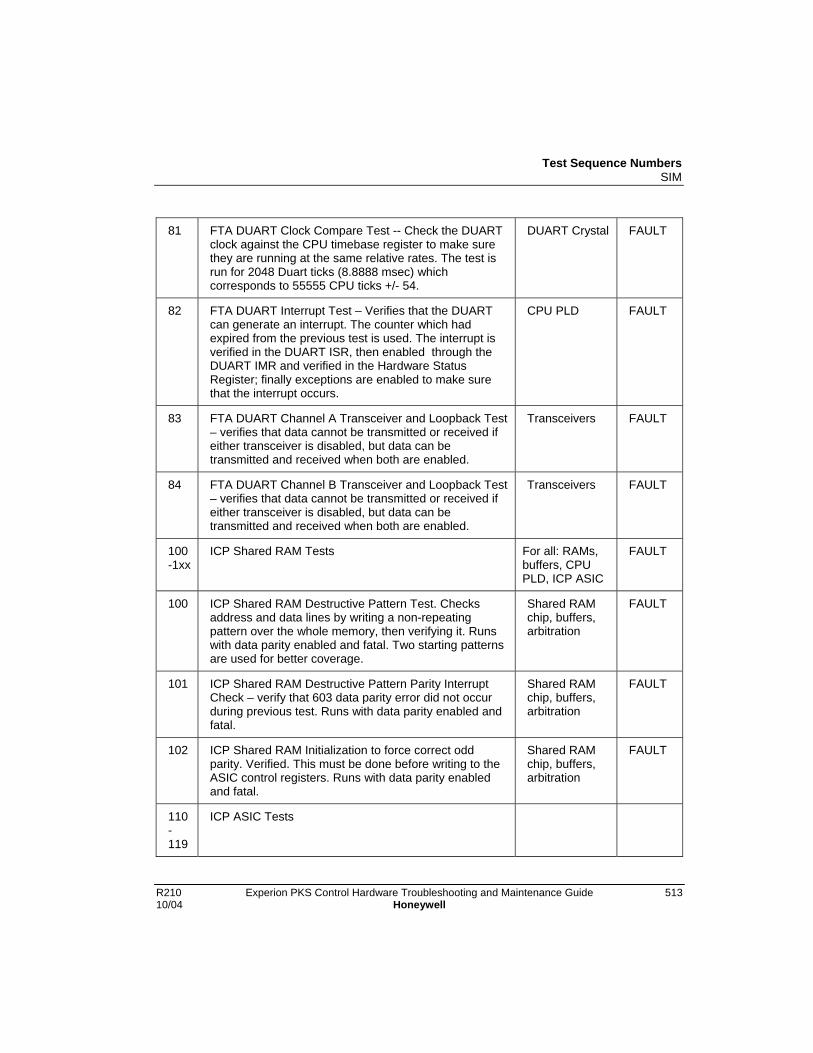
Test Sequence NumbersSIM
R210 Experion PKS Control Hardware Troubleshooting and Maintenance Guide 51310/04 Honeywell
81 FTA DUART Clock Compare Test -- Check the DUARTclock against the CPU timebase register to make surethey are running at the same relative rates. The test isrun for 2048 Duart ticks (8.8888 msec) whichcorresponds to 55555 CPU ticks +/- 54.
DUART Crystal FAULT
82 FTA DUART Interrupt Test – Verifies that the DUARTcan generate an interrupt. The counter which hadexpired from the previous test is used. The interrupt isverified in the DUART ISR, then enabled through theDUART IMR and verified in the Hardware StatusRegister; finally exceptions are enabled to make surethat the interrupt occurs.
CPU PLD FAULT
83 FTA DUART Channel A Transceiver and Loopback Test– verifies that data cannot be transmitted or received ifeither transceiver is disabled, but data can betransmitted and received when both are enabled.
Transceivers FAULT
84 FTA DUART Channel B Transceiver and Loopback Test– verifies that data cannot be transmitted or received ifeither transceiver is disabled, but data can betransmitted and received when both are enabled.
Transceivers FAULT
100-1xx
ICP Shared RAM Tests For all: RAMs,buffers, CPUPLD, ICP ASIC
FAULT
100 ICP Shared RAM Destructive Pattern Test. Checksaddress and data lines by writing a non-repeatingpattern over the whole memory, then verifying it. Runswith data parity enabled and fatal. Two starting patternsare used for better coverage.
Shared RAMchip, buffers,arbitration
FAULT
101 ICP Shared RAM Destructive Pattern Parity InterruptCheck – verify that 603 data parity error did not occurduring previous test. Runs with data parity enabled andfatal.
Shared RAMchip, buffers,arbitration
FAULT
102 ICP Shared RAM Initialization to force correct oddparity. Verified. This must be done before writing to theASIC control registers. Runs with data parity enabledand fatal.
Shared RAMchip, buffers,arbitration
FAULT
110-119
ICP ASIC Tests
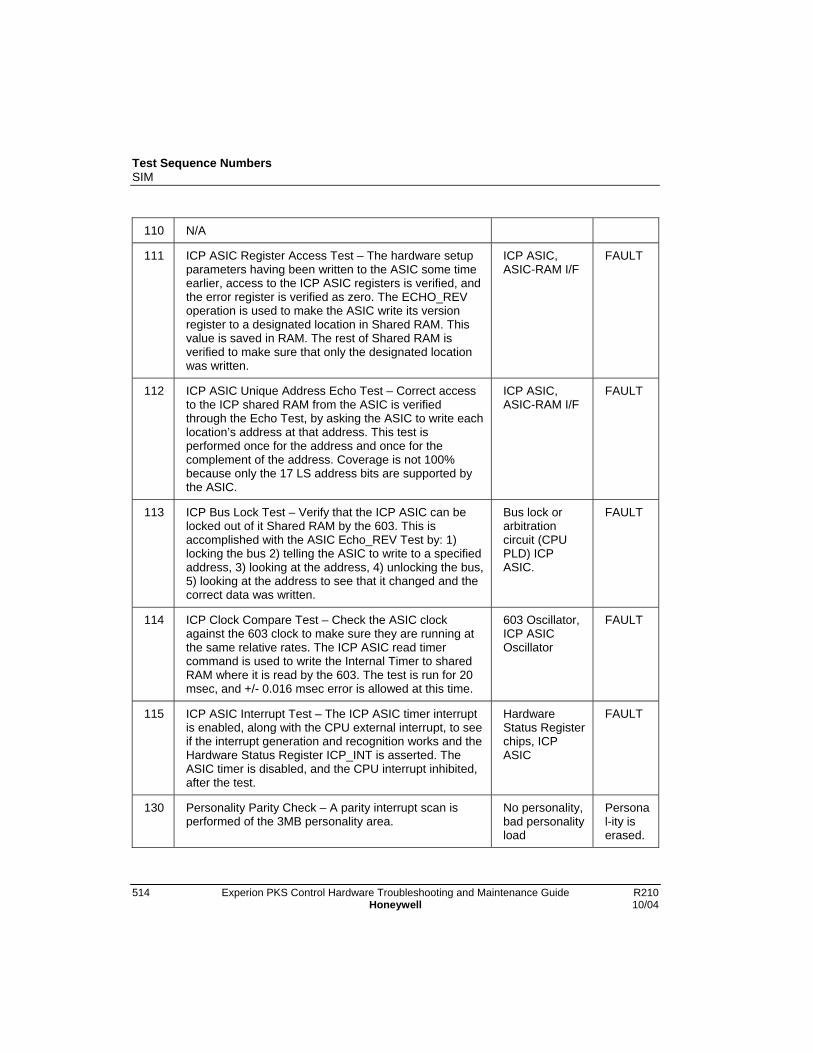
Test Sequence NumbersSIM
514 Experion PKS Control Hardware Troubleshooting and Maintenance Guide R210Honeywell 10/04
110 N/A
111 ICP ASIC Register Access Test – The hardware setupparameters having been written to the ASIC some timeearlier, access to the ICP ASIC registers is verified, andthe error register is verified as zero. The ECHO_REVoperation is used to make the ASIC write its versionregister to a designated location in Shared RAM. Thisvalue is saved in RAM. The rest of Shared RAM isverified to make sure that only the designated locationwas written.
ICP ASIC,ASIC-RAM I/F
FAULT
112 ICP ASIC Unique Address Echo Test – Correct accessto the ICP shared RAM from the ASIC is verifiedthrough the Echo Test, by asking the ASIC to write eachlocation’s address at that address. This test isperformed once for the address and once for thecomplement of the address. Coverage is not 100%because only the 17 LS address bits are supported bythe ASIC.
ICP ASIC,ASIC-RAM I/F
FAULT
113 ICP Bus Lock Test – Verify that the ICP ASIC can belocked out of it Shared RAM by the 603. This isaccomplished with the ASIC Echo_REV Test by: 1)locking the bus 2) telling the ASIC to write to a specifiedaddress, 3) looking at the address, 4) unlocking the bus,5) looking at the address to see that it changed and thecorrect data was written.
Bus lock orarbitrationcircuit (CPUPLD) ICPASIC.
FAULT
114 ICP Clock Compare Test – Check the ASIC clockagainst the 603 clock to make sure they are running atthe same relative rates. The ICP ASIC read timercommand is used to write the Internal Timer to sharedRAM where it is read by the 603. The test is run for 20msec, and +/- 0.016 msec error is allowed at this time.
603 Oscillator,ICP ASICOscillator
FAULT
115 ICP ASIC Interrupt Test – The ICP ASIC timer interruptis enabled, along with the CPU external interrupt, to seeif the interrupt generation and recognition works and theHardware Status Register ICP_INT is asserted. TheASIC timer is disabled, and the CPU interrupt inhibited,after the test.
HardwareStatus Registerchips, ICPASIC
FAULT
130 Personality Parity Check – A parity interrupt scan isperformed of the 3MB personality area.
No personality,bad personalityload
Personal-ity iserased.

Test Sequence NumbersSIM
R210 Experion PKS Control Hardware Troubleshooting and Maintenance Guide 51510/04 Honeywell
131 Personality Area Erase – If the previous test indicated aparity error, the 3MB personality area is erased andverified.
Bad flash chip FAULT
132 Personality checksum -- If the previous test indicated noparity error, and a personality is present, the personalitychecksum is verified. If no errors, a key is written inRAM to indicate that the personality is valid.
Bad personalityload
Personal-ity isignored.
255 PCM Signals end of selftest. The HEALTH LED is madeGREEN. Depending on various state flags and whetherRAM was flushed, selftest will exit to the Alive/Failexecutive or start the personality. Displays BOOT whenstarting the personality and PASS when starting theAlive executive.
N/A N/A

Test Sequence NumbersSIM
516 Experion PKS Control Hardware Troubleshooting and Maintenance Guide R210Honeywell 10/04
R210 Experion PKS Control Hardware Troubleshooting and Maintenance Guide 51710/04 Honeywell
Corrective Actions
General
GEN_CA01Call TAC for assistance.
GEN_CA02Cycle power to the chassis.
Corrective ActionsBEM
518 Experion PKS Control Hardware Troubleshooting and Maintenance Guide R210Honeywell 10/04
BEM
BEM_CA01Check the BEM.
If ... Then ...
If the BEM front panel indicatoris off,
Ensure chassis power is applied and/or BEM isfully inserted into the chassis.
If that doesn’t work, Replace the BEM.
BEM_CA02Recharge the BEM.
If ... Then ...
If the BEM OKLED is solid red,
1. Verify that the battery-pack has been inserted into the BEM(usually done at time of installation).
2. Otherwise, if the battery-pack is present, then its capacity isnot within spec. Replace the BEM to reinstate the battery-backed protection of the CPM control strategy and performthe following steps to attempt to repair the deficient BEM.
− Allow the BEM to recharge the battery-pack in a poweredchassis for 24 hours. The battery-pack may have originallybeen drained after the chassis has been powered down foran extended period of time.
− If the battery pack fails to charge after sitting in a poweredchassis for 24 hours, replace the battery-pack.
− If the BEM LED is not solid green with a new battery-pack,then the BEM circuitry and/or ICP connector is defective.Note that the battery-pack may still be salvaged byrecharging (for 24 hours in a powered chassis) using anotherBEM.
Corrective ActionsCNI
R210 Experion PKS Control Hardware Troubleshooting and Maintenance Guide 51910/04 Honeywell
CNI
CNI_CA01To replace a CNI,
If … Then …
the CNI resides in an“On-Control” PRIMARY,
• remove SECONDARY chassis power,
• then replace the PRIMARY CNI,
• then wait for the PRIMARY CNI to successfullycomplete startup,
• then return SECONDARY chassis power.
the CNI resides in an“Off-Control” PRIMARY,
• remove SECONDARY chassis power,
• then a few seconds later remove PRIMARY chassispower,
• then replace the PRIMARY CNI,
• then return PRIMARY chassis power,
• then wait for the PRIMARY to successfullycomplete startup,
• then return SECONDARY chassis power.
the CNI resides in aSECONDARY,
• remove SECONDARY chassis power,
• then replace the SECONDARY CNI,
• then return SECONDARY chassis power.

Corrective ActionsCNI
520 Experion PKS Control Hardware Troubleshooting and Maintenance Guide R210Honeywell 10/04
CNI_CA02To reset a CNI,
If … Then …
the CNI resides in an“On-Control” PRIMARY,
• remove SECONDARY chassis power,
• then remove and re-insert the PRIMARY CNI,
• then wait for the PRIMARY CNI to successfullycomplete startup,
• then return SECONDARY chassis power.
the CNI resides in an“Off-Control” PRIMARY,
• remove SECONDARY chassis power,
• then a few seconds later remove PRIMARY chassispower,
• then return PRIMARY chassis power,
• then wait for the PRIMARY to successfullycomplete startup,
• then return SECONDARY chassis power.
the CNI resides in aSECONDARY,
• remove SECONDARY chassis power,
• then return SECONDARY chassis power.
Corrective ActionsCPM
R210 Experion PKS Control Hardware Troubleshooting and Maintenance Guide 52110/04 Honeywell
CPM
CPM_CA01Check the CPM.
If ... Then ...
If all the CPM front panelindicators are off,
Ensure chassis power is applied and/or CPM is fullyinserted into the chassis.
If that doesn’t work, Replace the CPM CPM_CA06.
CPM_CA02Load the CPM firmware.
If ... Then ...
If the CPM is in theAlive or ReadyState,
Use the NetworkTools utility to load the CPM Boot and/orApplication personality firmware.
If the CPM is in theLoading State,
Await CPM Application or Boot personality-downloadcompletion. Otherwise, if the current firmware downloadsession terminated abnormally:
• Ensure downloading the correct personality for themodule type.
• Attempt to reload the CPM personality firmware usingthe NetworkTools utility.
• If repeated attempts to load CPM personality firmwareare unsuccessful, replace the CPM CPM_CA06.
CPM_CA03Isolate reason for loss-of-synchronization.
If ... Then ...
If RM COM LED isoff,
Ensure redundancy cable is present and attached to both theprimary and secondary RM.
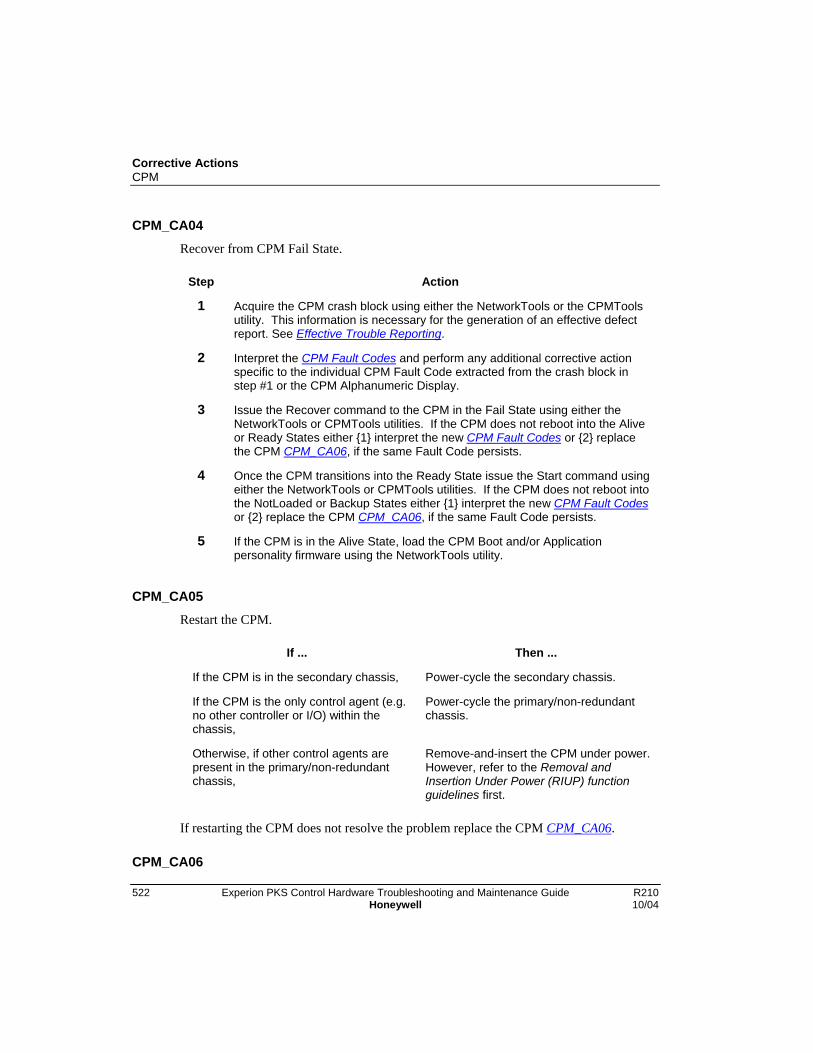
Corrective ActionsCPM
522 Experion PKS Control Hardware Troubleshooting and Maintenance Guide R210Honeywell 10/04
CPM_CA04Recover from CPM Fail State.
Step Action
1 Acquire the CPM crash block using either the NetworkTools or the CPMToolsutility. This information is necessary for the generation of an effective defectreport. See Effective Trouble Reporting.
2 Interpret the CPM Fault Codes and perform any additional corrective actionspecific to the individual CPM Fault Code extracted from the crash block instep #1 or the CPM Alphanumeric Display.
3 Issue the Recover command to the CPM in the Fail State using either theNetworkTools or CPMTools utilities. If the CPM does not reboot into the Aliveor Ready States either {1} interpret the new CPM Fault Codes or {2} replacethe CPM CPM_CA06, if the same Fault Code persists.
4 Once the CPM transitions into the Ready State issue the Start command usingeither the NetworkTools or CPMTools utilities. If the CPM does not reboot intothe NotLoaded or Backup States either {1} interpret the new CPM Fault Codesor {2} replace the CPM CPM_CA06, if the same Fault Code persists.
5 If the CPM is in the Alive State, load the CPM Boot and/or Applicationpersonality firmware using the NetworkTools utility.
CPM_CA05Restart the CPM.
If ... Then ...
If the CPM is in the secondary chassis, Power-cycle the secondary chassis.
If the CPM is the only control agent (e.g.no other controller or I/O) within thechassis,
Power-cycle the primary/non-redundantchassis.
Otherwise, if other control agents arepresent in the primary/non-redundantchassis,
Remove-and-insert the CPM under power.However, refer to the Removal andInsertion Under Power (RIUP) functionguidelines first.
If restarting the CPM does not resolve the problem replace the CPM CPM_CA06.
CPM_CA06
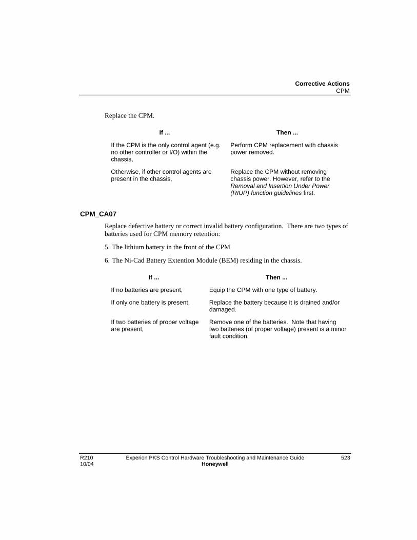
Corrective ActionsCPM
R210 Experion PKS Control Hardware Troubleshooting and Maintenance Guide 52310/04 Honeywell
Replace the CPM.
If ... Then ...
If the CPM is the only control agent (e.g.no other controller or I/O) within thechassis,
Perform CPM replacement with chassispower removed.
Otherwise, if other control agents arepresent in the chassis,
Replace the CPM without removingchassis power. However, refer to theRemoval and Insertion Under Power(RIUP) function guidelines first.
CPM_CA07
Replace defective battery or correct invalid battery configuration. There are two types ofbatteries used for CPM memory retention:
5. The lithium battery in the front of the CPM
6. The Ni-Cad Battery Extention Module (BEM) residing in the chassis.
If ... Then ...
If no batteries are present, Equip the CPM with one type of battery.
If only one battery is present, Replace the battery because it is drained and/ordamaged.
If two batteries of proper voltageare present,
Remove one of the batteries. Note that havingtwo batteries (of proper voltage) present is a minorfault condition.

Corrective ActionsCPM
524 Experion PKS Control Hardware Troubleshooting and Maintenance Guide R210Honeywell 10/04
CPM_CA08Check the RM resident in the CPM chassis.
If ... Then ...
If the RM faulted, Interpret the RM fault code.
Otherwise if the RM appearshealthy,
Either power-cycle the chassis or remove-and-replace the RM with power applied dependingwhether the RM is in the secondary or primaryredundancy role respectively.
If that doesn’t work, Restart the CPM CPM_CA05.
CPM_CA09
Activate the CPM control strategy using Control Builder or the appropriate SCANdisplay.
CPM_CA10
If necessary, create/modify control strategy using Control Builder. Load new/existingcontrol strategy using the Control Builder.
CPM_CA11Reload the CEE FB manually.
CPM_CA12Interpret the CPM Test Sequence Number displayed on the Alphanumeric Display.

Corrective ActionsCPM
R210 Experion PKS Control Hardware Troubleshooting and Maintenance Guide 52510/04 Honeywell
CPM_CA13
Recover from CPM Watchdog Timer timeout. The following recovery procedureassumes the CPM is the only control agent within the chassis. If this is not the case andthe CPM must be immediately recovered (i.e. without gathering defect information),simply restart the CPM
Step Action
1 Ensure a battery is present and power-cycle the CPM.
2 The CPM reboots into the Fail State displaying FAIL 0014.
3 Acquire the CPM crash block using either the NetworkTools or the CPMToolsutility.
4 Issue the Recover command to the Failed CPM using either the NetworkToolsor CPMTools utilities.
5 The CPM reboots into the Ready State.
6 Issue the Start command to the Ready CPM using either the NetworkTools orCPMTools utilities.
7 The CPM reboots into the NotLoaded or Backup State.
8 Replace the CPM if the Watchdog Timer timeout condition reoccurs.
CPM_CA14Isolate cause of ControlNet communication fault.
Step Action
1 Search the Experion PKS SCAN Alarm Summary display for any revealingindications as to which communication module and/or cable are in distress.
2 Repair CNI slot x (where x is the slot number embedded in the Experion PKSNotification text descriptor) communication fault between primary andsecondary chassis.
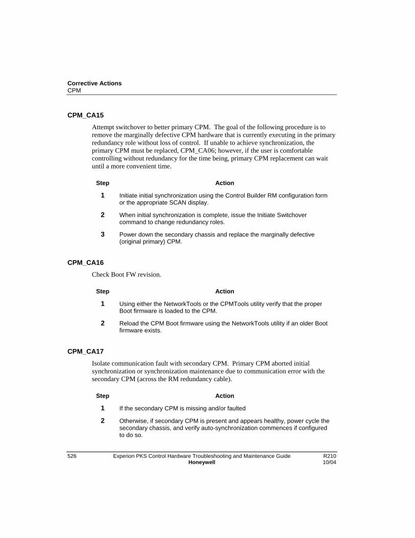
Corrective ActionsCPM
526 Experion PKS Control Hardware Troubleshooting and Maintenance Guide R210Honeywell 10/04
CPM_CA15
Attempt switchover to better primary CPM. The goal of the following procedure is toremove the marginally defective CPM hardware that is currently executing in the primaryredundancy role without loss of control. If unable to achieve synchronization, theprimary CPM must be replaced, CPM_CA06; however, if the user is comfortablecontrolling without redundancy for the time being, primary CPM replacement can waituntil a more convenient time.
Step Action
1 Initiate initial synchronization using the Control Builder RM configuration formor the appropriate SCAN display.
2 When initial synchronization is complete, issue the Initiate Switchovercommand to change redundancy roles.
3 Power down the secondary chassis and replace the marginally defective(original primary) CPM.
CPM_CA16Check Boot FW revision.
Step Action
1 Using either the NetworkTools or the CPMTools utility verify that the properBoot firmware is loaded to the CPM.
2 Reload the CPM Boot firmware using the NetworkTools utility if an older Bootfirmware exists.
CPM_CA17
Isolate communication fault with secondary CPM. Primary CPM aborted initialsynchronization or synchronization maintenance due to communication error with thesecondary CPM (across the RM redundancy cable).
Step Action
1 If the secondary CPM is missing and/or faulted
2 Otherwise, if secondary CPM is present and appears healthy, power cycle thesecondary chassis, and verify auto-synchronization commences if configuredto do so.

Corrective ActionsCPM
R210 Experion PKS Control Hardware Troubleshooting and Maintenance Guide 52710/04 Honeywell
CPM_CA18Recover from secondary I/O CNI ControlNet communication fault.
Step Action
1 If a secondary CNI is faulted, power-cycle the secondary chassis.
2 If a primary CNI is faulted, remove and reinsert the CNI with chassis-powerapplied (or power-cycle the primary chassis if not performing control).
CPM_CA19Check CPM Application firmware compatibility.
CPM_CA20Check CPM hardware compatibility.

Corrective ActionsI/O Modules
528 Experion PKS Control Hardware Troubleshooting and Maintenance Guide R210Honeywell 10/04
I/O Modules
IO_CA01With chassis power removed, replace the I/O module.
IO_CA02Without removing chassis power, replace the I/O module.
IO_CA03Without removing chassis power, remove and re-insert the I/O module.

Corrective ActionsRack and Supply
R210 Experion PKS Control Hardware Troubleshooting and Maintenance Guide 52910/04 Honeywell
Rack and Supply
CH_CA01To replace a chassis power supply.
If … Then …
the supply resides in an “On-Control” PRIMARY,
• take the controller “Off Control”,
• then remove SECONDARY chassis power,
• then a few seconds later remove PRIMARYchassis power,
• then replace the PRIMARY supply,
• then repower the PRIMARY and wait forstartup to successfully complete,
• then return SECONDARY chassis power.
the supply resides in an “Off-Control” PRIMARY,
• remove SECONDARY chassis power,
• then a few seconds later remove PRIMARYchassis power,
• then replace the PRIMARY supply,
• then repower the PRIMARY and wait forstartup to successfully complete,
• then return SECONDARY chassis power.
the supply resides in aSECONDARY,
• remove SECONDARY chassis power,
• then replace the SECONDARY supply,
• then return SECONDARY chassis power.
the supply resides in a non-redundant controller or in anI/O rack,
• remove chassis power,
• then replace the supply,
• then return chassis power.
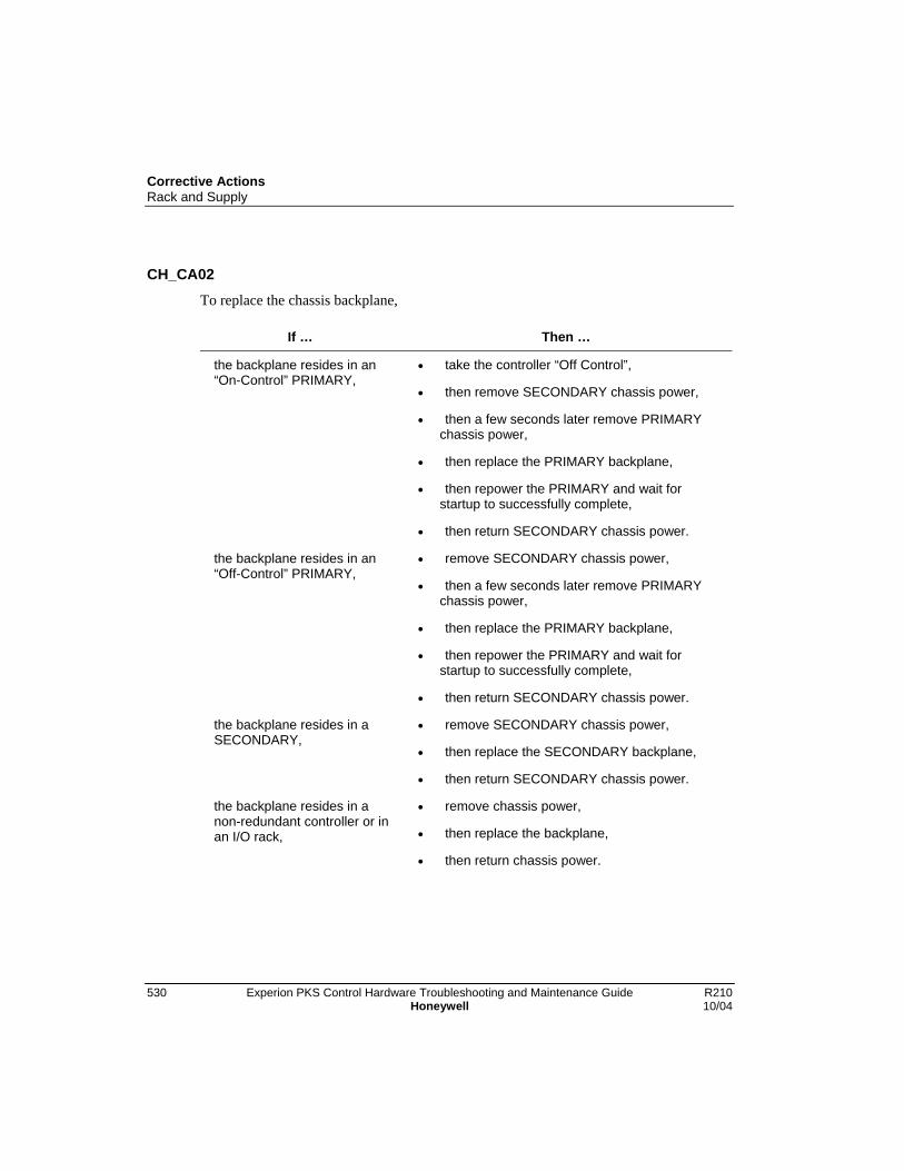
Corrective ActionsRack and Supply
530 Experion PKS Control Hardware Troubleshooting and Maintenance Guide R210Honeywell 10/04
CH_CA02To replace the chassis backplane,
If … Then …
the backplane resides in an“On-Control” PRIMARY,
• take the controller “Off Control”,
• then remove SECONDARY chassis power,
• then a few seconds later remove PRIMARYchassis power,
• then replace the PRIMARY backplane,
• then repower the PRIMARY and wait forstartup to successfully complete,
• then return SECONDARY chassis power.
the backplane resides in an“Off-Control” PRIMARY,
• remove SECONDARY chassis power,
• then a few seconds later remove PRIMARYchassis power,
• then replace the PRIMARY backplane,
• then repower the PRIMARY and wait forstartup to successfully complete,
• then return SECONDARY chassis power.
the backplane resides in aSECONDARY,
• remove SECONDARY chassis power,
• then replace the SECONDARY backplane,
• then return SECONDARY chassis power.
the backplane resides in anon-redundant controller or inan I/O rack,
• remove chassis power,
• then replace the backplane,
• then return chassis power.
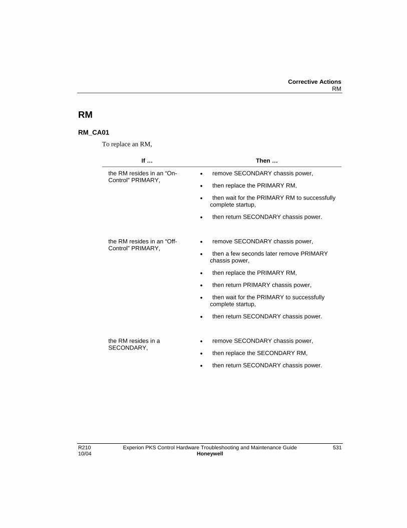
Corrective ActionsRM
R210 Experion PKS Control Hardware Troubleshooting and Maintenance Guide 53110/04 Honeywell
RM
RM_CA01To replace an RM,
If … Then …
the RM resides in an “On-Control” PRIMARY,
• remove SECONDARY chassis power,
• then replace the PRIMARY RM,
• then wait for the PRIMARY RM to successfullycomplete startup,
• then return SECONDARY chassis power.
the RM resides in an “Off-Control” PRIMARY,
• remove SECONDARY chassis power,
• then a few seconds later remove PRIMARYchassis power,
• then replace the PRIMARY RM,
• then return PRIMARY chassis power,
• then wait for the PRIMARY to successfullycomplete startup,
• then return SECONDARY chassis power.
the RM resides in aSECONDARY,
• remove SECONDARY chassis power,
• then replace the SECONDARY RM,
• then return SECONDARY chassis power.

Corrective ActionsRM
532 Experion PKS Control Hardware Troubleshooting and Maintenance Guide R210Honeywell 10/04
RM_CA02To reset an RM,
If … Then …
the RM resides in an “On-Control” PRIMARY,
• remove SECONDARY chassis power,
• then remove and re-insert the PRIMARY RM,
• then wait for the PRIMARY RM to successfullycomplete startup,
• then return SECONDARY chassis power.
the RM resides in an “Off-Control” PRIMARY,
• remove SECONDARY chassis power,
• then a few seconds later remove PRIMARYchassis power,
• then return PRIMARY chassis power,
• then wait for the PRIMARY to successfullycomplete startup,
• then return SECONDARY chassis power.
the RM resides in aSECONDARY,
• remove SECONDARY chassis power,
• then return SECONDARY chassis power.
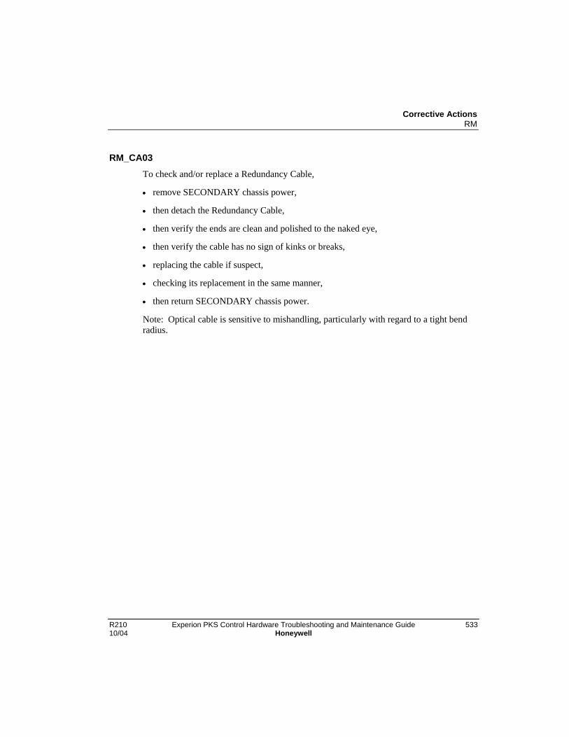
Corrective ActionsRM
R210 Experion PKS Control Hardware Troubleshooting and Maintenance Guide 53310/04 Honeywell
RM_CA03To check and/or replace a Redundancy Cable,
• remove SECONDARY chassis power,
• then detach the Redundancy Cable,
• then verify the ends are clean and polished to the naked eye,
• then verify the cable has no sign of kinks or breaks,
• replacing the cable if suspect,
• checking its replacement in the same manner,
• then return SECONDARY chassis power.
Note: Optical cable is sensitive to mishandling, particularly with regard to a tight bendradius.

Corrective ActionsRM
534 Experion PKS Control Hardware Troubleshooting and Maintenance Guide R210Honeywell 10/04

R210 Experion PKS Control Hardware Troubleshooting and Maintenance Guide 53510/04 Honeywell
Network Configurations
Overview
Addressing
You set the MAC ID (ControlNet address) switches on the partner CNI modules in anRCP to the same ID (address). The software automatically assigns the switch set addressto the Primary Controller and increments the set address by one for the SecondaryController. For example, if you set the switches on the partner CNI modules to 1 for theSupervisory ControlNet, the address of the Primary Controller is always 1 and theaddress for the Secondary Controller is always 2. You must always allocate twoconsecutive addresses for partner CNI modules in an RCP.

Network ConfigurationsOverview
536 Experion PKS Control Hardware Troubleshooting and Maintenance Guide R210Honeywell 10/04
Remote I/O Modules
B A B A B A B A
Redundancy Cable (GN-KRR011)
CNI (TC-CCR011, MAC Setting = 3)
B A
I/OChassis
I/O (Field Devices)
I/O ControlNet
ToServer
RedundantChassisPair
CNI (TC-CCR012, MAC Setting = 1)
C200 CPM (TC-PRS021)
CNI (TC-CCR012, MAC Setting = 1)
RM (TC-PRR021)
CNI (TC-CCR012, MAC Setting = 1)
C200 CPM (TC-PRS021)
CNI (TC-CCR012, MAC Setting = 1)
RM (TC-PRR021)

Network ConfigurationsComplying with minimum redundant controller system requirements
R210 Experion PKS Control Hardware Troubleshooting and Maintenance Guide 53710/04 Honeywell
Complying with minimum redundant controller systemrequirements
Rules for Conjoined Networks
You must comply with the following system configuration rule, when your ExperionPKS system supports controller redundancy.
• Any ControlNet segment that connects to an RCP must have at least two other nodes.A node can be a CNI in another chasssis, KTC, PCIC, Linking Device, Series A/HGateway, etc.
The following sample system configurations show how you can adapt a given smallsystem architecture to meet minimum redundant controller system requirements.
• If your system only consists of a non-redundant Server or redundant Servers, oneRCP, and one I/O chassis, you must link the Supervisory ControlNet with the I/OControlNet though a trunk cable to form a common ControlNet as shown in the figurebelow. In this case, the default addresses are as follows.
− Default address for CNI in slot 0 is 1.
− Default address for CNI in slot 3 is 5.
− Note that the default address for the I/O Chassis CNI in slot 0 is 3.

Network ConfigurationsComplying with minimum redundant controller system requirements
538 Experion PKS Control Hardware Troubleshooting and Maintenance Guide R210Honeywell 10/04
Optional Redundant
Server
Remote I/O Modules
OperatorStation
Ethernet
Non- Redundant Server
B A B A
CNI C200 CPM CNI RM
B A B A B A B A
Redundancy Cable
RedundantChassisPair
CNI
B A
I/OChassis
I/O (Field Devices)
CommonControlNet
CNI C200 CPM CNI RM
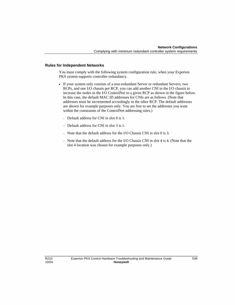
Network ConfigurationsComplying with minimum redundant controller system requirements
R210 Experion PKS Control Hardware Troubleshooting and Maintenance Guide 53910/04 Honeywell
Rules for Independent Networks
You must comply with the following system configuration rule, when your ExperionPKS system supports controller redundancy.
• If your system only consists of a non-redundant Server or redundant Servers, twoRCPs, and one I/O chassis per RCP, you can add another CNI in the I/O chassis toincrease the nodes in the I/O ControlNet to a given RCP as shown in the figure below.In this case, the default MAC ID addresses for CNIs are as follows. (Note thataddresses must be incremented accordingly in the other RCP. The default addressesare shown for example purposes only. You are free to set the addresses you wantwithin the constraints of the ControlNet addressing rules.)
− Default address for CNI in slot 0 is 1.
− Default address for CNI in slot 3 is 1.
− Note that the default address for the I/O Chassis CNI in slot 0 is 3.
− Note that the default address for the I/O Chassis CNI in slot 4 is 4. (Note that theslot 4 location was chosen for example purposes only.)

Network ConfigurationsComplying with minimum redundant controller system requirements
540 Experion PKS Control Hardware Troubleshooting and Maintenance Guide R210Honeywell 10/04
Optional Redundant
Server
Remote I/O Modules
OperatorStation
Ethernet
Non- Redundant Server
B A B A
CNI C200 CPM CNI RM
B A B A B A B A
Redundancy Cable
RedundantChassisPair
B A
I/OChassis
I/O (Field Devices)
CNI CNI
CNI C200 CPM CNI RM
SupervisoryControlNetTo
OtherRCP
I/O ControlNet
B A

Network ConfigurationsInvalid Configuration
R210 Experion PKS Control Hardware Troubleshooting and Maintenance Guide 54110/04 Honeywell
Invalid Configuration
Example
The figure below shows an invalid redundant controller system configuration forreference only. Do not add additional CNIs to an RCP as the means to increase thenumber of nodes in a ControlNet segment to a single I/O chassis. This does not meet therequirement of having at least two nodes in any ControlNet segment that connects to anRCP.
Optional Redundant
Server
Remote I/O Modules
OperatorStation
Ethernet
Non- Redundant Server
B A B A
CNI C200 CPM CNI RM
B A B A B A B A B A B A
Redundancy Cable
RedundantChassisPair
CNI
B A
I/OChassis
I/O (Field Devices)
CNI CNI
CNI C200 CPM CNI RM
SupervisoryControlNet
I/O ControlNet

Network ConfigurationsChecklists
542 Experion PKS Control Hardware Troubleshooting and Maintenance Guide R210Honeywell 10/04
Checklists
Guidelines for assigning MAC ID/ControlNet addressesBe sure your MAC ID assignments conform to these general guidelines.
• Valid Supervisory ControlNet address range is between 1 to 24. Note that 24 can beextended up to 32, if your system has more than 24 nodes present.
• Valid I/O ControlNet address range is between 1 to 20.
• Assign 23 as the address for the Server. This reserves address 24 for an optionalredundant partner Server.
CAUTION
When reconfiguring the Server MAC ID from 19/20 to 23/24 for the first time,you must first change the Supervisory ControlNet UMAX parameter to 24.Otherwise, a loss of view occurs.
• ControlNet address 1 is now optional (even though the documentation assumes that itis always present). The CNI node with the lowest MAC ID controls the NUT timingfor the CNET segment it is in.
• When you assign the lowest MAC ID to an operating CNI in an RCP, do not assignthe next higher used address above “lowest MAC ID + 1” (in the same physicalnetwork) to another CNI in that RCP. You must assign the next higher used addressabove “lowest MAC ID + 1” to a CNI in another Controller chassis, a CNI in a remoteI/O chassis, or the PCIC card in the Server in the same physical network. (Note thatthe examples shown in Figures 2, 3, and 4 comply with this rule.)
• Only assign odd numbered addresses to accommodate the logical assignment ofodd/even address pairs for RCP applications.
• Assign same odd numbered address to CNI partners in an RCP.
Refer to the Experion PKS Planning Guide, Supervisory ControlNet Addressing for moreaddress guidelines.

Network ConfigurationsChecklists
R210 Experion PKS Control Hardware Troubleshooting and Maintenance Guide 54310/04 Honeywell
Confirming redundant controller system requirementsBe sure your redundant controller system architecture includes:
− At least four nodes. This means that there must be at least two other nodes in anyControlNet segment that connects to an RCP.
− Redundant-compliant C200 CPMs and CNIs in RCP.
− CPMs, CNIs, and RMs located in matching slots in RCP.
− Partner CNIs in RCP have same odd numbered address.
− Partner CNIs in RCP have same ControlNet parameter settings.
− RMs connected by a redundancy cable for each RCP.
− No local I/O in any RCP.
− RCP that includes a CNI with the lowest MAC ID of the ControlNet segment doesnot also include a CNI with the next higher used address above “lowest MAC ID +1” in the same physical network.

Network ConfigurationsChecklists
544 Experion PKS Control Hardware Troubleshooting and Maintenance Guide R210Honeywell 10/04

R210 Experion PKS Control Hardware Troubleshooting and Maintenance Guide 54510/04 Honeywell
RM (Workstation) Displays
Introduction
Overview
Experion PKS offers RM Displays from both Control Builder and Station. The datawhich feeds these displays is the same. The presentations are similar. References (in tisdocument) to these displays apply in general to both the CB and Station versions.
The RM Displays provide not only a view to the RM’s themselves, but also a means tomonitor and control Redundancy within a given redundant chassis pair (RCP).
The displays offer an indication of the general Redundancy state of each chassis of anRCP along with several tabs/categories of detailed Redundancy related data andcommand features.
This section will discuss these displays with the emphasis on their use as diagnostic tools

RM (Workstation) DisplaysRedundancy Terminology
546 Experion PKS Control Hardware Troubleshooting and Maintenance Guide R210Honeywell 10/04
Redundancy Terminology
Definitions
These definitions are listed in order of complexity, and are given in the context ofprocess and machine control.
• Device (Chassis)
• Assigned Functions
• On-Line vs. Off-Line
• Availability
• Redundancy
• Dual Redundancy
• RCP (supported at the chassis level only)
• Redundancy State
• Primary
• Secondary
• Secondary Readiness
• Switchover
• Chassis ID

RM (Workstation) DisplaysAccessing RM Displays
R210 Experion PKS Control Hardware Troubleshooting and Maintenance Guide 54710/04 Honeywell
Accessing RM Displays
Control Builder RM Displays
In Control Builder, under the Monitor tab, double click on the icon of the target RM, e.g.,“RM0103”.
Once the dialog box appears, select the tab (pane) of interest.
Note the data from both chassis appears on one display.
Station RM DisplaysIn Station, enter the target RM identifier (e.g., “RM0103”) on the tool bar and hit F12.
Once in the display, select the display of interest using the buttons along the upper edgeof the display.
Note that data from only one chassis appears. To see the partner data, hit the “ShowSecondary” or “Show Primary” button in the lower left corner.

RM (Workstation) DisplaysSummary (CB) or Main (Stn) Panes
548 Experion PKS Control Hardware Troubleshooting and Maintenance Guide R210Honeywell 10/04
Summary (CB) or Main (Stn) Panes
Purpose
These displays serve as a summary. In many instances, this summary is sufficient foroperator interaction.
Diagnostic Features
Feature Diagnostics
(Visibility) Is data being retrieved from the target RMs?
Redundancy State Are states opposing (one PRIMARY, the otherSECONDARY)?
Are states as expected?
Secondary Readiness Is this state as expected (DISQUALIFIED,SYNCHRONIZING, SYNCHRONIZED)?
Module Are modules present and placed as expected?
Compatibility Do modules consider themselves compatible with theirpartners?
ATTENTION: The RM always displays UNDEFINED.
% Complete If Secondary Readiness is DISQUALIFIED, is this value 0?
Otherwise, is this value approaching (or at) 100% as themodules approach (or reach) Synchronization?
ATTENTION: The RM will always report 0.

RM (Workstation) DisplaysRM Profiles (CB and Stn) Panes
R210 Experion PKS Control Hardware Troubleshooting and Maintenance Guide 54910/04 Honeywell
RM Profiles (CB and Stn) Panes
PurposeA view to check and compare identity, revisions, and states of the RM’s.
Diagnostic Features
Feature Diagnostics
(Visibility) Is data being retrieved from the target RMs?
Redundancy State Are states opposing (one PRIMARY, the otherSECONDARY)?
Are states as expected?
Secondary Readiness Is this state as expected (DISQUALIFIED,SYNCHRONIZING, SYNCHRONIZED)?
Compatibility Are module version and revisions compatible (i.e., have thesame ver./rev/ numbers?
Are Product Types 112 and Product Codes 1?
Do vendor codes match?
Are Serial Numbers different?
Are Chassis ID’s opposing (one CHASSIS_A, the otherCHASSIS_B)?
ATTENTION: Mismatches may be allowed. Refer torelease documentation.
General State Are both RM’s OK?
Auto-Sync Option,
Auto-Sync State,
Program CommandRecognition
Do these 3 items match?
Error Code Is this field blank (…)?
If not, does the code remain after 1 minute?

RM (Workstation) DisplaysRM Profiles (CB and Stn) Panes
550 Experion PKS Control Hardware Troubleshooting and Maintenance Guide R210Honeywell 10/04
Feature Diagnostics
Fault Bits Are any Major fault bits set?
ATTENTION: Minor fault bits should not hinder normaloperations.
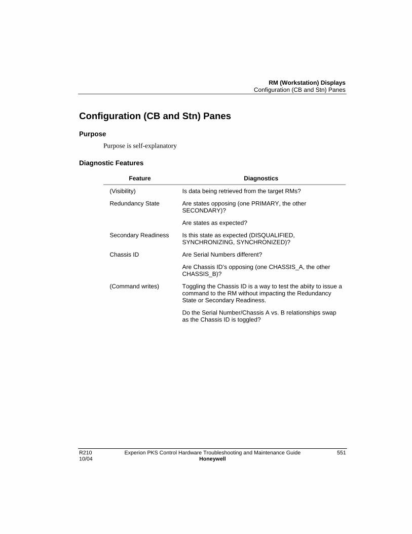
RM (Workstation) DisplaysConfiguration (CB and Stn) Panes
R210 Experion PKS Control Hardware Troubleshooting and Maintenance Guide 55110/04 Honeywell
Configuration (CB and Stn) Panes
PurposePurpose is self-explanatory
Diagnostic Features
Feature Diagnostics
(Visibility) Is data being retrieved from the target RMs?
Redundancy State Are states opposing (one PRIMARY, the otherSECONDARY)?
Are states as expected?
Secondary Readiness Is this state as expected (DISQUALIFIED,SYNCHRONIZING, SYNCHRONIZED)?
Chassis ID Are Serial Numbers different?
Are Chassis ID’s opposing (one CHASSIS_A, the otherCHASSIS_B)?
(Command writes) Toggling the Chassis ID is a way to test the abiity to issue acommand to the RM without impacting the RedundancyState or Secondary Readiness.
Do the Serial Number/Chassis A vs. B relationships swapas the Chassis ID is toggled?

RM (Workstation) DisplaysSynchronization (CB) and Synch (Stn) Panes
552 Experion PKS Control Hardware Troubleshooting and Maintenance Guide R210Honeywell 10/04
Synchronization (CB) and Synch (Stn) Panes
Purpose
This display offers the user the broadest set of features related to controlling andmonitoring RCP Synchronization.
Diagnostic Features
Feature Diagnostics
(Visibility) Is data being retrieved from the target RMs?
Redundancy State Are states opposing (one PRIMARY, the otherSECONDARY)?
Are states as expected?
Secondary Readiness Is this state as expected (DISQUALIFIED,SYNCHRONIZING, SYNCHRONIZED)?
Auto-SynchronizationState
Does this state track the Auto-Sychronization Option as itshould?
e.g.,
IF Auto-Synchroniation Option = ALWAYS,
Then Auto-Synchronization State should be ENABLED.
ELSE IF Auto-Synchroniation Option = NEVER,
Then Auto-Synchronization State should be DISABLED.
ELSE Auto-Synchroniation Option = CONDITION,
Then Auto-Synchronization State can be ENABLED orDISABLED.
Module Are modules present and placed as expected?
Compatibility Do modules consider themselves compatible with theirpartners?
ATTENTION: The RM always displays UNDEFINED.

RM (Workstation) DisplaysSynchronization (CB) and Synch (Stn) Panes
R210 Experion PKS Control Hardware Troubleshooting and Maintenance Guide 55310/04 Honeywell
Feature Diagnostics
% Complete If Secondary Readiness is DISQUALIFIED, is this value 0?
Otherwise, is this value approaching (or at) 100% as themodules approach (or reach) Synchronization?
ATTENTION: The RM will always report 0.

RM (Workstation) DisplaysChassis Profiles (CB and Stn) Panes
554 Experion PKS Control Hardware Troubleshooting and Maintenance Guide R210Honeywell 10/04
Chassis Profiles (CB and Stn) Panes
PurposeThese displays offer the user the broadest set of feature for diagnosing a problem RCP.
The objective of these displays is to pinpoint the problem slot or module. From there, theuser must refer to module specific displays and documentation to further isolate theproblem.
Diagnostic Features
Feature Diagnostics
(Visibility) Is data being retrieved from the target RMs?
Redundancy State Are states opposing (one PRIMARY, the otherSECONDARY)?
Are states as expected?
Secondary Readiness Is this state as expected (DISQUALIFIED,SYNCHRONIZING, SYNCHRONIZED)?
Module Are modules present and placed as expected?
Does every module have a partner?
General State Are both existing modules OK?
Compatibility Do modules consider themselves compatible with theirpartners?
ATTENTION: The RM always displays UNDEFINED.
% Complete If Secondary Readiness is DISQUALIFIED, is this value 0?
Otherwise, is this value approaching (or at) 100% as themodules approach (or reach) Synchronization?
ATTENTION: The RM will always report 0.
Secondary Readiness(module-specific)
Is this state as expected (DISQUALIFIED,SYNCHRONIZING, SYNCHRONIZED)?

RM (Workstation) DisplaysDisplay (CB) Pane
R210 Experion PKS Control Hardware Troubleshooting and Maintenance Guide 55510/04 Honeywell
Display (CB) Pane
PurposeThis display offers no significant diagnostic usefulness.
Server Parameters (CB) Pane
PurposeThis display offers no significant diagnostic usefulness.

RM (Workstation) DisplaysServer Parameters (CB) Pane
556 Experion PKS Control Hardware Troubleshooting and Maintenance Guide R210Honeywell 10/04

R210 Experion PKS Control Hardware Troubleshooting and Maintenance Guide 55710/04 Honeywell
Tools and Utilities
CPM Tools
Introduction
CPM Tools is a command line (pcmana.exe), diagnostic application intended for internalExperion PKS Engineering usage. Certain situations, however, merit its usage bycustomers.
This utility supports both Ethernet and ControlNet networks. With the posibility ofhaving multiple RSLinx drivers, the user must first select the driver needed tocommunicate with the module under investigation. A list of currently configured driversis presented to the user that the user can select from. Once a driver is selected, the mainmenu is presented to the user. Note that all of the functionality offered on the main menucan be obtained by using the NetworkTools application.

Tools and UtilitiesCPM Tools
558 Experion PKS Control Hardware Troubleshooting and Maintenance Guide R210Honeywell 10/04
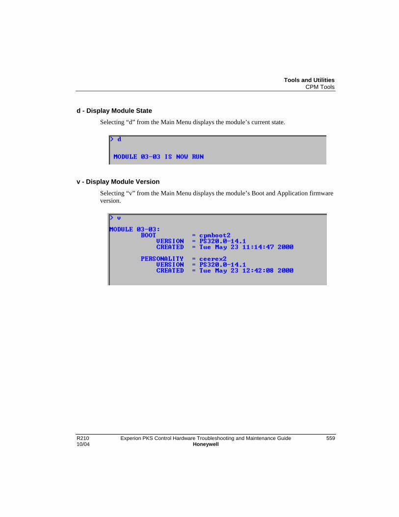
Tools and UtilitiesCPM Tools
R210 Experion PKS Control Hardware Troubleshooting and Maintenance Guide 55910/04 Honeywell
d - Display Module StateSelecting “d” from the Main Menu displays the module’s current state.
v - Display Module Version
Selecting “v” from the Main Menu displays the module’s Boot and Application firmwareversion.

Tools and UtilitiesCPM Tools
560 Experion PKS Control Hardware Troubleshooting and Maintenance Guide R210Honeywell 10/04
b - Display Module Startup Information
Selecting “b” from the Main Menu displays the module’s reasoning for vetoing aRetention Startup. The first non-false reason encountered in the list indicates whyRetention Startup was not possible. More specifically, the list of reasons, from top-to-bottom, is ordered in the sequence that the controller performs the test on the individualitems.
For example, the following illustrates the Startup Information for a controller that did notperform Retention Startup because it was rebooted as a consequence of Applicationfirmware upgrade:
As another example, the following illustrates the Startup Information for a controller thatdid perform Retention Startup:
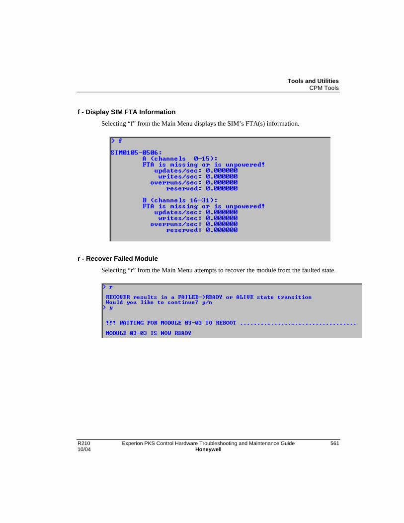
Tools and UtilitiesCPM Tools
R210 Experion PKS Control Hardware Troubleshooting and Maintenance Guide 56110/04 Honeywell
f - Display SIM FTA InformationSelecting “f” from the Main Menu displays the SIM’s FTA(s) information.
r - Recover Failed ModuleSelecting “r” from the Main Menu attempts to recover the module from the faulted state.
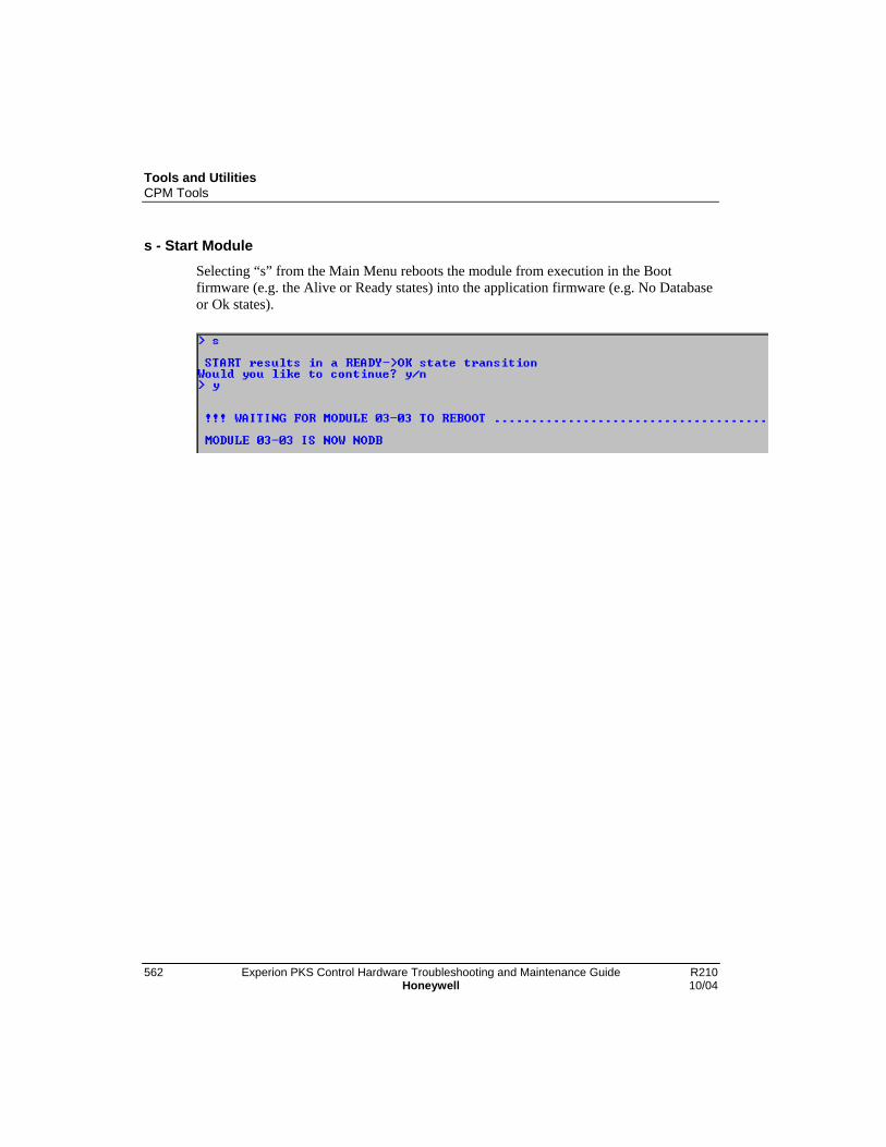
Tools and UtilitiesCPM Tools
562 Experion PKS Control Hardware Troubleshooting and Maintenance Guide R210Honeywell 10/04
s - Start Module
Selecting “s” from the Main Menu reboots the module from execution in the Bootfirmware (e.g. the Alive or Ready states) into the application firmware (e.g. No Databaseor Ok states).
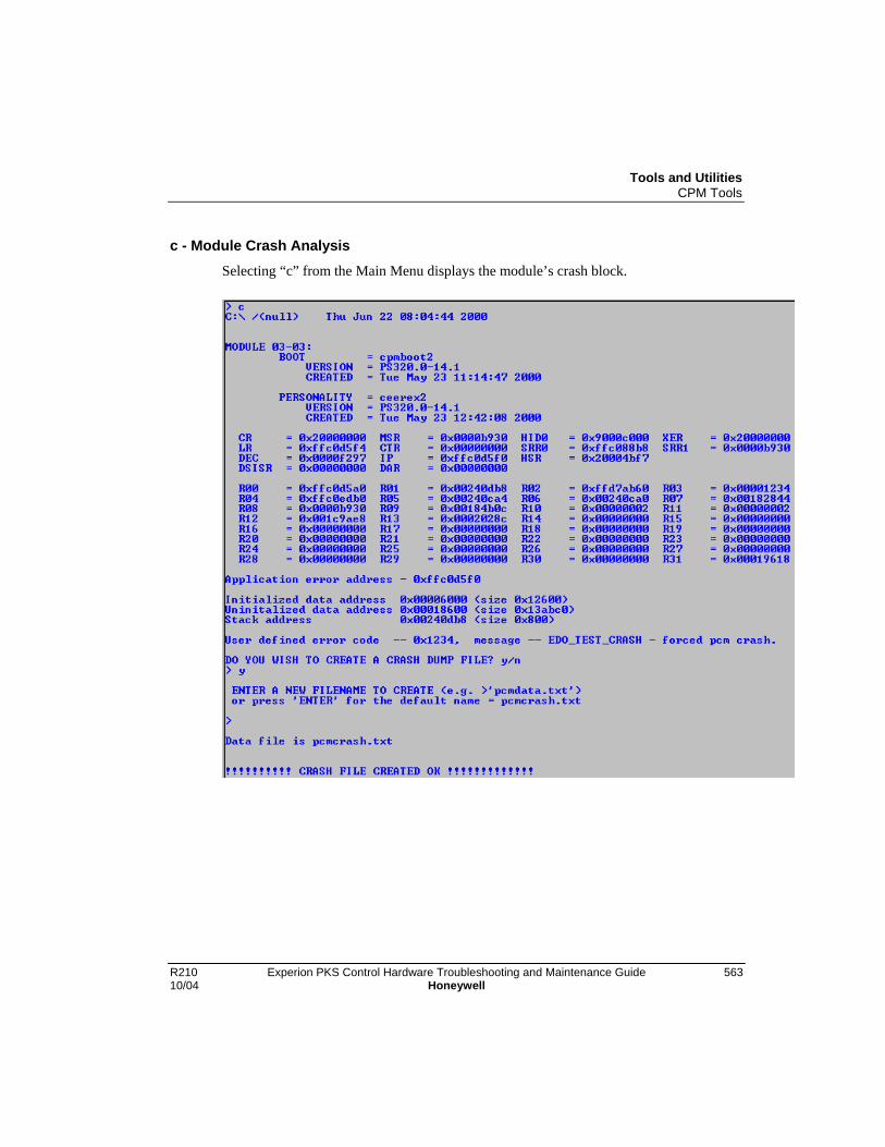
Tools and UtilitiesCPM Tools
R210 Experion PKS Control Hardware Troubleshooting and Maintenance Guide 56310/04 Honeywell
c - Module Crash AnalysisSelecting “c” from the Main Menu displays the module’s crash block.

Tools and UtilitiesCPM Tools
564 Experion PKS Control Hardware Troubleshooting and Maintenance Guide R210Honeywell 10/04
l - Load Module Program Image
Selecting “l” from the Main Menu allows the user to update the module’s Boot orApplication firmware.

Tools and UtilitiesCPM Tools
R210 Experion PKS Control Hardware Troubleshooting and Maintenance Guide 56510/04 Honeywell
p - Select New Module Path
Selecting “p” from the Main Menu allows the user to change the communication path tothe module under investigation.

Tools and UtilitiesCPM Tools
566 Experion PKS Control Hardware Troubleshooting and Maintenance Guide R210Honeywell 10/04
t - Force Shutdown Of Module
Selecting “t” from the Main Menu forces the module to transition to the Ready State.This option is useful when performing module firmware update.
CAUTION
Use extreme caution when forcing shutdown and double check that the pathis properly specified because execution of this option results in an immediateloss-of-control.
x - Exit ProgramSelecting “x” from the Main Menu exits the CPM Tools application.
Tools and UtilitiesUsing DBADMIN
R210 Experion PKS Control Hardware Troubleshooting and Maintenance Guide 56710/04 Honeywell
Using DBADMIN
IntroductionThe Database Administration (DBADMIN) tool is a utility for maintaining theEngineering Repository Database (ERDB) used by the Experion PKS system to createand maintain the control strategies. It enables users to initiate the following databasemaintenance tasks:
• Display and clear locks left in the ERDB and/or Custom Alogrithm Block (CAB) afterabnormal termination of the Control Builder or CAB configuration.
• Restore the “clean” database in the primary ERDB.
• Detach and copy the primary ERDB to specified location.
• Check the consistency of the ERDB.
• Re-organize data and index pages, and update statistics of the ERDB.
• Expand the size of the ERDB database.
• Create a backup of the current database.
• Restore a backup database in the primary ERDB.
• Synchronize the Qualification and Version Control System (QVCS) database with theERDB and clear any QVCS locks
• Create a backup of the current QVCS database.
• Restore a backup of the current database.
And, for redundant Servers only:
• Recover a Primary or Secondary ERDB.
• Synchronize ERDBs to start and stop replication.
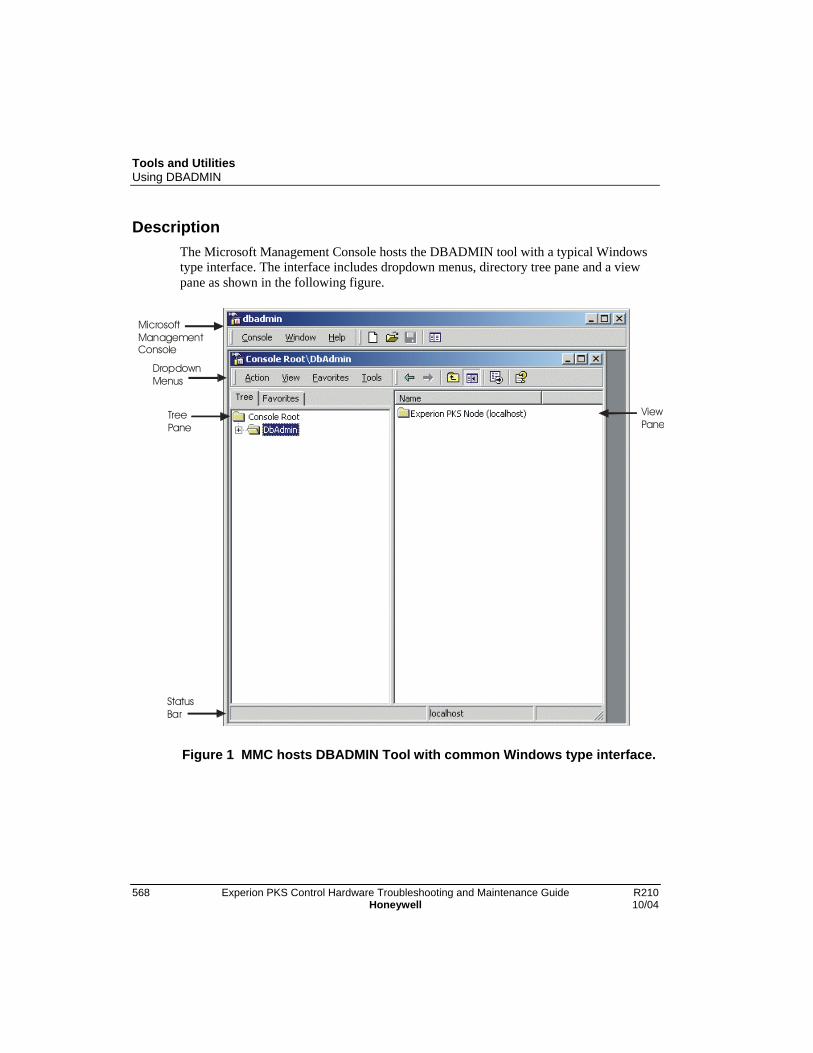
Tools and UtilitiesUsing DBADMIN
568 Experion PKS Control Hardware Troubleshooting and Maintenance Guide R210Honeywell 10/04
DescriptionThe Microsoft Management Console hosts the DBADMIN tool with a typical Windowstype interface. The interface includes dropdown menus, directory tree pane and a viewpane as shown in the following figure.
MicrosoftManagement Console
Tree Pane
ViewPane
StatusBar
Dropdown Menus
Figure 1 MMC hosts DBADMIN Tool with common Windows type interface.

Tools and UtilitiesUsing DBADMIN
R210 Experion PKS Control Hardware Troubleshooting and Maintenance Guide 56910/04 Honeywell
Some Terms
Term Definition
CAB Custom Algorithm Block
EMB Enterprise Model Builder
ERDB The Experion PKS Engineering Repository relationaldatabase.
Master Also referred to as Design Master or Primary ERDB.The primary copy of a redundant ERDB.
ODBC (Open Database Connectivity) - A protocol foraccessing databases that is used by Experion PKSapplications.
Replica A secondary or backup copy of the ERDB that ismaintained in sync with the design master.
Replicated An ERDB that has been ] synchronized copies forERDB redundancy purposes.
SQL (Structured Query Language) - A databasesublanguage used in querying, updating, andmanaging relational databases. Used by ExperionPKS applications to access the ERDB.
Synchronize The process of copying database informationbetween master and replica to bring both copies upto date.
VCS Qualification and Version Control System
InstallationThe DBADMIN tool (dbadmin.msc) executable resides in this Experion PKS directoryProgram Files\Honeywell\Experion PKS\Engineering Tools\system\bin. It is installedas part of the Experion PKS process software installation procedure for EngineeringTools.
Tools and UtilitiesUsing DBADMIN
570 Experion PKS Control Hardware Troubleshooting and Maintenance Guide R210Honeywell 10/04
Startup
Considerations
• You have previously logged onto Configuration Studio with appropriate security levelto initiate actions through the DBADMIN tool
Use the following procedure to launch the DBADMIN tool.
Step Action Result
1 Click the Start button on the taskbar.Click Programs>Honeywell ExperionPKS>Server>Configuration Studio.
Launches the Configuratin Studio.
2 On Connect dialog, select applicableExperion Server. Click the Connectbutton
Opens Server direcory in ConfigurationExplorer tree view.
3 Click Control Strategy icon. Opens Categories in view window.
On Process Control Strategiescategory, click Administer the controlstrategy database.
Launches the DbAdmin utility.

Tools and UtilitiesUsing DBADMIN
R210 Experion PKS Control Hardware Troubleshooting and Maintenance Guide 57110/04 Honeywell
Step Action Result
Tools and UtilitiesUsing DBADMIN
572 Experion PKS Control Hardware Troubleshooting and Maintenance Guide R210Honeywell 10/04
2 Click the plus sign for DbAdmin foldericon and then plus sign for Server foldericon.
Expands Server directory of databasefunctions.
4 Please go to the next section Menu ortree pane functions for a list of thefunctions you can initiate using this utility.

Tools and UtilitiesUsing DBADMIN
R210 Experion PKS Control Hardware Troubleshooting and Maintenance Guide 57310/04 Honeywell
Menu or tree pane functions
The following table summarizes the functions you can initiate through a given menu ortree pane selection for reference. If you are familiar with working in a Windows typeenvironment, you should be able to intuitively interact with all the functions providedthrough DBADMIN tool menu selections. Please note that the selections available in agiven menu will vary depending on the current active function.
Click This MenuSelection . . .
To Initiate This Function . . .
Action->New Windowfrom Here
Opens new console root window.
Action->New TaskpadView
Open New Taskpad View Wizard to create anothertaskpad view.
Action->Export List Opens Save as dialog box to save data as text file tospecified location.
Action->Help Calls up Microsoft Management Console help.

Tools and UtilitiesUsing DBADMIN
574 Experion PKS Control Hardware Troubleshooting and Maintenance Guide R210Honeywell 10/04
Click This MenuSelection . . .
To Initiate This Function . . .
View->Choose Columns Calls up Modify Columns dialog box. Use buttonsprovided to move, remove, or add columns as applicable.
View->Large Icons Changes view to use Large Icons style.
View->Small Icons Changes view to use Small Icons style.

Tools and UtilitiesUsing DBADMIN
R210 Experion PKS Control Hardware Troubleshooting and Maintenance Guide 57510/04 Honeywell
Click This MenuSelection . . .
To Initiate This Function . . .
View->List Changes view to use List style.
View->Detail Changes view to use Detail style.
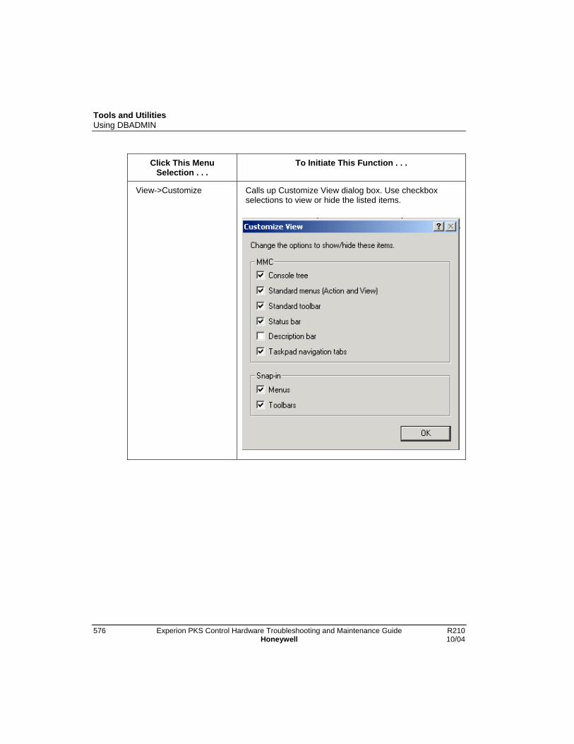
Tools and UtilitiesUsing DBADMIN
576 Experion PKS Control Hardware Troubleshooting and Maintenance Guide R210Honeywell 10/04
Click This MenuSelection . . .
To Initiate This Function . . .
View->Customize Calls up Customize View dialog box. Use checkboxselections to view or hide the listed items.

Tools and UtilitiesUsing DBADMIN
R210 Experion PKS Control Hardware Troubleshooting and Maintenance Guide 57710/04 Honeywell
Click This MenuSelection . . .
To Initiate This Function . . .
Favorites->Add Favorites Calls up Add to Favorites dialog box. Lets you add viewsto favorites tab. Favorite is also added to the Favoritesdropdown menu.
Favorites->OrganizeFavorites
Opens Organize Favorites dialog box. Lets you createfolders and move items into folders.

Tools and UtilitiesUsing DBADMIN
578 Experion PKS Control Hardware Troubleshooting and Maintenance Guide R210Honeywell 10/04
Click This MenuSelection . . .
To Initiate This Function . . .
Tools->Change Node Opens the Login Information dialog box. Lets youconnect to the specified system node in a multi-serverenvironment. Just enter your password and ServerName, domanin, and click the OK button.
Tools->Refresh Status Refresh data in View pane. (Only active for selecteddirectory tree functions.)

Tools and UtilitiesUsing DBADMIN
R210 Experion PKS Control Hardware Troubleshooting and Maintenance Guide 57910/04 Honeywell
Click This MenuSelection . . .
To Initiate This Function . . .
Tools->User Filter Opens the Set the User ID for Lock Filtering dialog box.Lets you restrict lock access to the specified user for theselected node. The value entered is saved in theWindows Registry and becomes the default for the nextsession. The user ID includes the machine name and thelogin name for the user whose locks are to be cleared.The default selection is “All Users”, which defeats the “byuser” filtering mechanism. (Only active for selecteddirectory tree functions.)
Tools->Refresh Locks Refreshes the View pane to show the most current lockinformation in the ERDB or CAB. (Only active forselected directory tree functions.)
Tools->Clear All Locks Clears all the current locks in the ERDB or CAB. Thecurrent User Filter setting is applied, when clearing thelist of associated locks. (Only active for selected directorytree functions.)
Click this Tree PaneSelection . . .
To Initiate This Function . . .
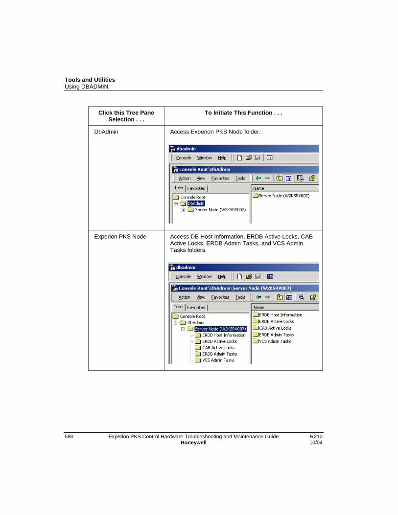
Tools and UtilitiesUsing DBADMIN
580 Experion PKS Control Hardware Troubleshooting and Maintenance Guide R210Honeywell 10/04
Click this Tree PaneSelection . . .
To Initiate This Function . . .
DbAdmin Access Experion PKS Node folder.
Experion PKS Node Access DB Host Information, ERDB Active Locks, CABActive Locks, ERDB Admin Tasks, and VCS AdminTasks folders.

Tools and UtilitiesUsing DBADMIN
R210 Experion PKS Control Hardware Troubleshooting and Maintenance Guide 58110/04 Honeywell
Click this Tree PaneSelection . . .
To Initiate This Function . . .
DB Host Information Display host name, type, and status in the View pane.
ATTENTION
Before clearing locks or performing database operations at a remoteserver node, insure that tasks such as Control Builder andImport/Export are shut down at that node.
ERDB Active Lock Display active locks in the View pane. (Click Tools->Clear All Locks or right-click in open area of view paneand select Clear All Locks from pop-up menu to clearcurrent locks from the database.)
CAB Active Lock Display active locks in the View pane. (Click Tools->Clear All Locks or right-click in open area of view paneand select Clear All Locks from pop-up menu to clearcurrent locks from CAB.)
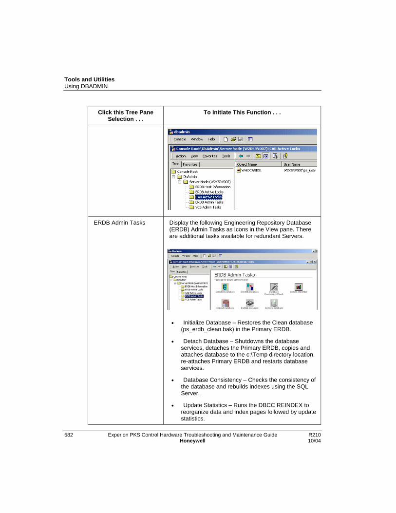
Tools and UtilitiesUsing DBADMIN
582 Experion PKS Control Hardware Troubleshooting and Maintenance Guide R210Honeywell 10/04
Click this Tree PaneSelection . . .
To Initiate This Function . . .
ERDB Admin Tasks Display the following Engineering Repository Database(ERDB) Admin Tasks as Icons in the View pane. Thereare additional tasks available for redundant Servers.
• Initialize Database – Restores the Clean database(ps_erdb_clean.bak) in the Primary ERDB.
• Detach Database – Shutdowns the databaseservices, detaches the Primary ERDB, copies andattaches database to the c:\Temp directory location,re-attaches Primary ERDB and restarts databaseservices.
• Database Consistency – Checks the consistency ofthe database and rebuilds indexes using the SQLServer.
• Update Statistics – Runs the DBCC REINDEX toreorganize data and index pages followed by updatestatistics.
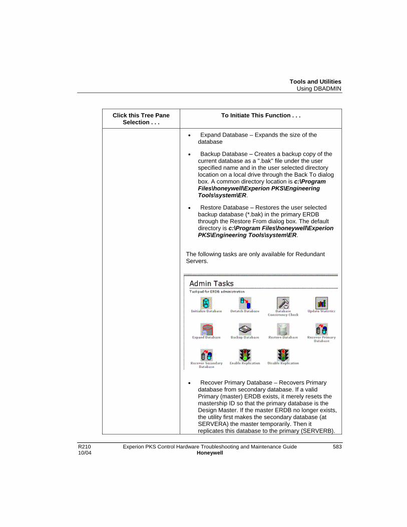
Tools and UtilitiesUsing DBADMIN
R210 Experion PKS Control Hardware Troubleshooting and Maintenance Guide 58310/04 Honeywell
Click this Tree PaneSelection . . .
To Initiate This Function . . .
• Expand Database – Expands the size of thedatabase
• Backup Database – Creates a backup copy of thecurrent database as a ".bak" file under the userspecified name and in the user selected directorylocation on a local drive through the Back To dialogbox. A common directory location is c:\ProgramFiles\honeywell\Experion PKS\EngineeringTools\system\ER.
• Restore Database – Restores the user selectedbackup database (*.bak) in the primary ERDBthrough the Restore From dialog box. The defaultdirectory is c:\Program Files\honeywell\ExperionPKS\Engineering Tools\system\ER.
The following tasks are only available for RedundantServers.
• Recover Primary Database – Recovers Primarydatabase from secondary database. If a validPrimary (master) ERDB exists, it merely resets themastership ID so that the primary database is theDesign Master. If the master ERDB no longer exists,the utility first makes the secondary database (atSERVERA) the master temporarily. Then itreplicates this database to the primary (SERVERB).

Tools and UtilitiesUsing DBADMIN
584 Experion PKS Control Hardware Troubleshooting and Maintenance Guide R210Honeywell 10/04
Click this Tree PaneSelection . . .
To Initiate This Function . . .
Finally, it switches mastership back to the new copyat SERVERB.
• Recover Secondary Database – RecoversSecondary database from Primary database. Itcreates a new replica from the Design Master, whichis assumed to be located at the path set by datasource `ps_erdb'. It creates the new replica at theserver node previously specified during installationas the secondary ERDB server.
• Enable Replication – Starts replication of the ERDBfrom the Primary to the Secondary. This enablesreplication from scratch.
• Disable Replication – Stops the replication functioncompletely. This is not a temporary interruption ofthe replication function.
VCS Admin Tasks Display the following Qualification and Version ControlSystem (QVCS) Admin Tasks as Icons in the View pane.
• Synchronize VCS - Synchronizes the Qualificationand Version Control System database with theEngineering Repository database and clears anyQVCS locks.
• Backup VCS Database – Creates a backup copy ofthe current QVCS database as a ".bak" file under theuser specified name and in the user selecteddirectory location on a local drive through the BackTo dialog box. A common directory location is

Tools and UtilitiesUsing DBADMIN
R210 Experion PKS Control Hardware Troubleshooting and Maintenance Guide 58510/04 Honeywell
Click this Tree PaneSelection . . .
To Initiate This Function . . .
c:\Program Files\honeywell\ExperionPKS\Engineering Tools\ER.
• Restore VCS Database – Restores the userselected backup QVCS database (*.bak) in theprimary ERDB through the Restore From dialog box.The default directory is c:\ProgramFiles\honeywell\Experion PKS\EngineeringTools\ER.
Selecting a Remote Server Node
Use the following procedure to select another Server in a multiple server environment.This means you not have to be physically located at the Server where DBADMINfunctions need to be done. This procedure assumes that you have started the DBADMINutility as outlined in the previous Startup section.
ATTENTION
Be sure applications such as Control Builder and Import/Export are shutdown at the remote Server node before initiating any DBADMIN operations.
Step Action Result
1 Click the DbAdmin folder. Selects the folder and adds the Toolsmenu to the toolbar.

Tools and UtilitiesUsing DBADMIN
586 Experion PKS Control Hardware Troubleshooting and Maintenance Guide R210Honeywell 10/04
Step Action Result
2 Click Tools-Change Node. Calls up the Login dialog box.
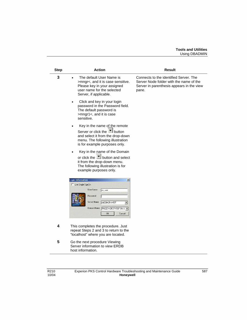
Tools and UtilitiesUsing DBADMIN
R210 Experion PKS Control Hardware Troubleshooting and Maintenance Guide 58710/04 Honeywell
Step Action Result
3 • The default User Name is>mngr<, and it is case sensitive.Please key in your assigneduser name for the selectedServer, if applicable.
• Click and key in your loginpassword in the Password field.The default password is>mngr1<, and it is casesensitive.
• Key in the name of the remoteServer or click the buttonand select it from the drop-downmenu. The following illustrationis for example purposes only.
• Key in the name of the Domainor click the button and selectit from the drop-down menu.The following illustration is forexample purposes only.
Connects to the identified Server. TheServer Node folder with the name of theServer in parenthesis appears in the viewpane.
4 This completes the procedure. Justrepeat Steps 2 and 3 to return to the“localhost” where you are located.
5 Go the next procedure ViewingServer information to view ERDBhost information.
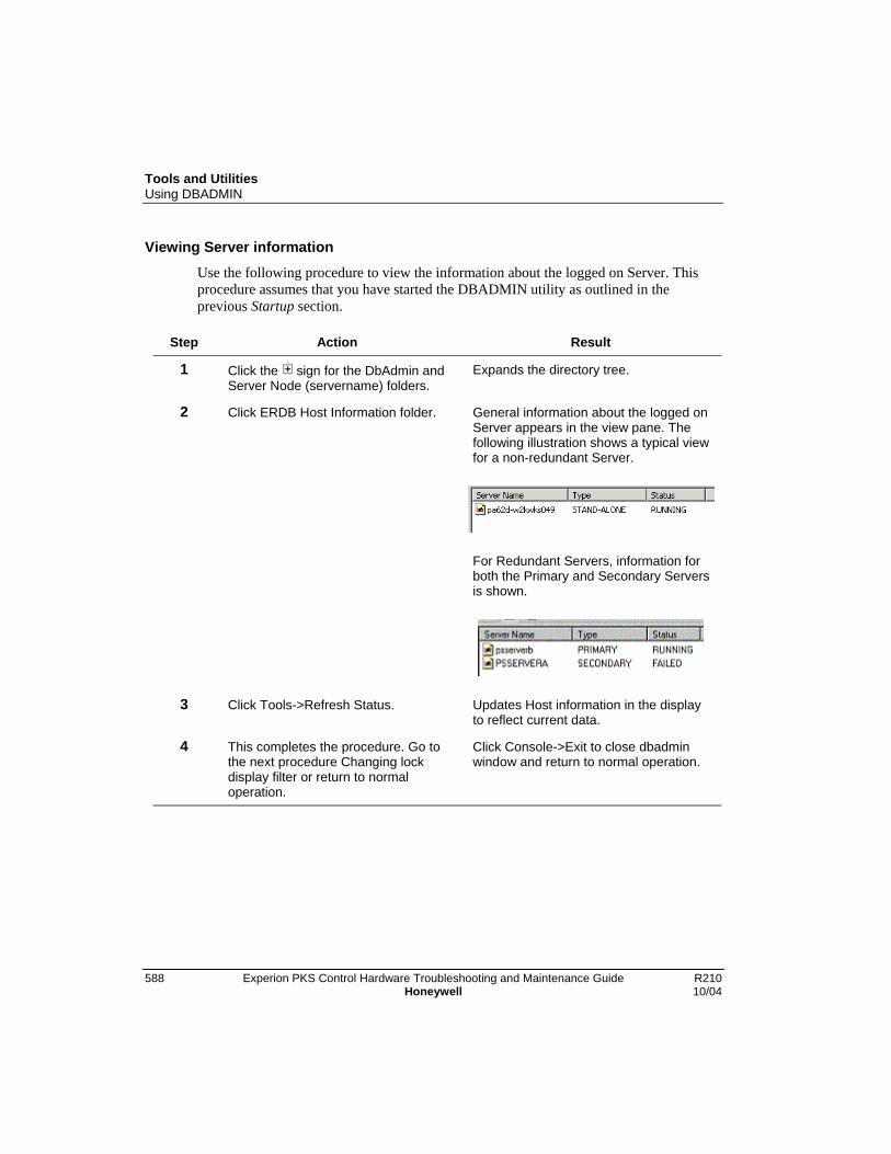
Tools and UtilitiesUsing DBADMIN
588 Experion PKS Control Hardware Troubleshooting and Maintenance Guide R210Honeywell 10/04
Viewing Server information
Use the following procedure to view the information about the logged on Server. Thisprocedure assumes that you have started the DBADMIN utility as outlined in theprevious Startup section.
Step Action Result
1 Click the sign for the DbAdmin andServer Node (servername) folders.
Expands the directory tree.
2 Click ERDB Host Information folder. General information about the logged onServer appears in the view pane. Thefollowing illustration shows a typical viewfor a non-redundant Server.
For Redundant Servers, information forboth the Primary and Secondary Serversis shown.
3 Click Tools->Refresh Status. Updates Host information in the displayto reflect current data.
4 This completes the procedure. Go tothe next procedure Changing lockdisplay filter or return to normaloperation.
Click Console->Exit to close dbadminwindow and return to normal operation.
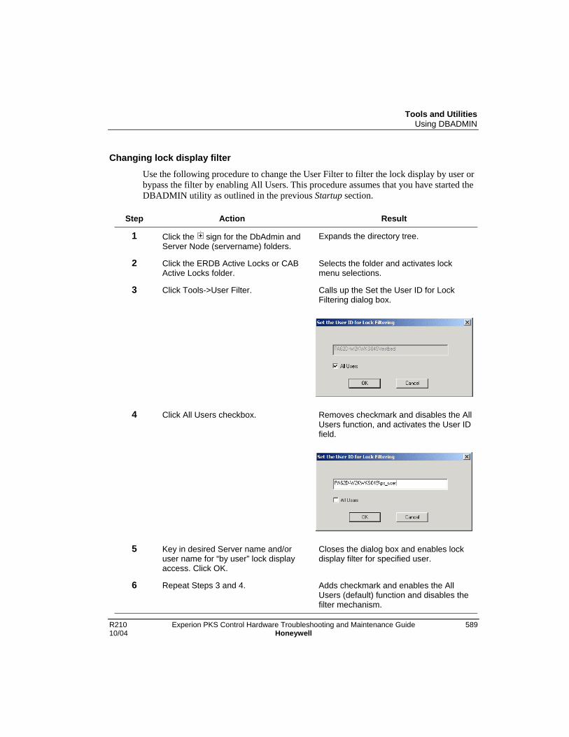
Tools and UtilitiesUsing DBADMIN
R210 Experion PKS Control Hardware Troubleshooting and Maintenance Guide 58910/04 Honeywell
Changing lock display filter
Use the following procedure to change the User Filter to filter the lock display by user orbypass the filter by enabling All Users. This procedure assumes that you have started theDBADMIN utility as outlined in the previous Startup section.
Step Action Result
1 Click the sign for the DbAdmin andServer Node (servername) folders.
Expands the directory tree.
2 Click the ERDB Active Locks or CABActive Locks folder.
Selects the folder and activates lockmenu selections.
3 Click Tools->User Filter. Calls up the Set the User ID for LockFiltering dialog box.
4 Click All Users checkbox. Removes checkmark and disables the AllUsers function, and activates the User IDfield.
5 Key in desired Server name and/oruser name for “by user” lock displayaccess. Click OK.
Closes the dialog box and enables lockdisplay filter for specified user.
6 Repeat Steps 3 and 4. Adds checkmark and enables the AllUsers (default) function and disables thefilter mechanism.
Tools and UtilitiesUsing DBADMIN
590 Experion PKS Control Hardware Troubleshooting and Maintenance Guide R210Honeywell 10/04
Step Action Result
7 Click OK. Closes the dialog box and refreshes thelock display for all users.
8 This completes the procedure. Go tothe next procedure Clearing currentlocks or return to normal operation.
Click Console->Exit to close dbadminwindow and return to normal operation.

Tools and UtilitiesUsing DBADMIN
R210 Experion PKS Control Hardware Troubleshooting and Maintenance Guide 59110/04 Honeywell
Clearing current locks
Use the following procedure to clear current locks in the database. This procedureassumes that you have started the DBADMIN utility as outlined in the previous Startupsection and set the desired lock display filter as outlined in the prior procedure.
Step Action Result
1 Click the sign for the DbAdmin andServer Node (servername) folders.
Expands the directory tree.
2 Click the ERDB Active Locks or CABActive Locks folder.
Selects the folder, activates lock menuselections, and displays current locks inthe view pane.
3 Click Tools->Refresh Locks. Updates the display to make sure theview is current.
TIP
You can also right-click the cursor in an open area in the view pane and selectRefresh Locks or Clear All Locks from the pop-up menu.
4 Click Tools->Clear All Locks. Clears current locks from the databaseand the view pane.
5 This completes the procedure. Go tothe next procedure Making a backupdatabase or return to normal operation.
Click Console->Exit to close dbadminwindow and return to normal operation.

Tools and UtilitiesUsing DBADMIN
592 Experion PKS Control Hardware Troubleshooting and Maintenance Guide R210Honeywell 10/04
Making a Backup database
Use the following procedure to make a backup copy of the current database. Thisprocedure assumes that you have started the DBADMIN utility as outlined in theprevious Startup section.
ATTENTION
It is a good idea to close the Control Builder application while running theDBADMIN utility.
Step Action Result
1 Click the sign for the DbAdmin andServer Node (servername) folders.
Expands the directory tree.
2 Click the ERDB Admin Tasks folder. Calls up ERDB Admin Tasks in the viewpane.
3 Are you using a redundant Server? If the answer is Yes, go to the next Step.
If the answer is No, go to Step 6.
4 Be sure you are logged onto the Serverwith the Primary database.
Want to Backup the Design Master(Primary) database.
5 Click the Disable Replication icon. Stops the replication function.

Tools and UtilitiesUsing DBADMIN
R210 Experion PKS Control Hardware Troubleshooting and Maintenance Guide 59310/04 Honeywell
Step Action Result
6 Click the Backup Database icon. Calls up one of the following dialogboxes depending on QVCS license.
With QVCS license, Select and/orCreate a folder to store backup setdialog – Go to Step 7:
Without QVCS license, Backup Todialog – Go to Step 9:
7 Click button in the Look in field toselect the desired folder and/or use thefolder buttons on the dialog to navigateto another folder or create a new folder.
Define location to backup database ascomplete set.
8 Click the Select button. Calls up confirmation dialog, click the OKbutton to initiate the backup. Go to Step11.
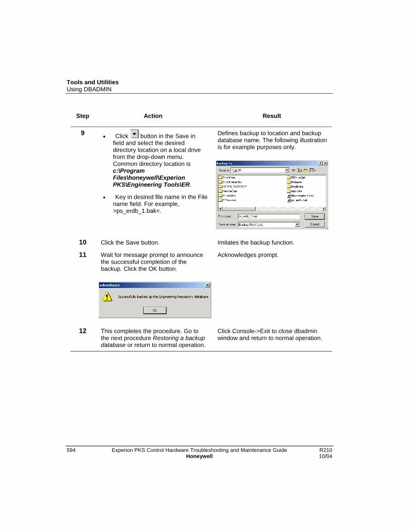
Tools and UtilitiesUsing DBADMIN
594 Experion PKS Control Hardware Troubleshooting and Maintenance Guide R210Honeywell 10/04
Step Action Result
9 • Click button in the Save infield and select the desireddirectory location on a local drivefrom the drop-down menu.Common directory location isc:\ProgramFiles\honeywell\ExperionPKS\Engineering Tools\ER.
• Key in desired file name in the Filename field. For example,>ps_erdb_1.bak<.
Defines backup to location and backupdatabase name. The following illustrationis for example purposes only.
10 Click the Save button. Imitates the backup function.
11 Wait for message prompt to announcethe successful completion of thebackup. Click the OK button.
Acknowledges prompt.
12 This completes the procedure. Go tothe next procedure Restoring a backupdatabase or return to normal operation.
Click Console->Exit to close dbadminwindow and return to normal operation.
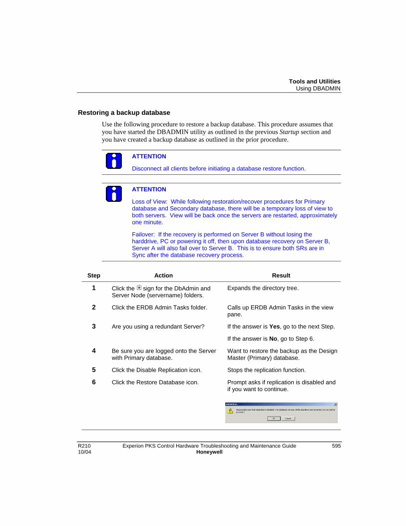
Tools and UtilitiesUsing DBADMIN
R210 Experion PKS Control Hardware Troubleshooting and Maintenance Guide 59510/04 Honeywell
Restoring a backup database
Use the following procedure to restore a backup database. This procedure assumes thatyou have started the DBADMIN utility as outlined in the previous Startup section andyou have created a backup database as outlined in the prior procedure.
ATTENTION
Disconnect all clients before initiating a database restore function.
ATTENTION
Loss of View: While following restoration/recover procedures for Primarydatabase and Secondary database, there will be a temporary loss of view toboth servers. View will be back once the servers are restarted, approximatelyone minute.
Failover: If the recovery is performed on Server B without losing theharddrive, PC or powering it off, then upon database recovery on Server B,Server A will also fail over to Server B. This is to ensure both SRs are inSync after the database recovery process.
Step Action Result
1 Click the sign for the DbAdmin andServer Node (servername) folders.
Expands the directory tree.
2 Click the ERDB Admin Tasks folder. Calls up ERDB Admin Tasks in the viewpane.
3 Are you using a redundant Server? If the answer is Yes, go to the next Step.
If the answer is No, go to Step 6.
4 Be sure you are logged onto the Serverwith Primary database.
Want to restore the backup as the DesignMaster (Primary) database.
5 Click the Disable Replication icon. Stops the replication function.
6 Click the Restore Database icon. Prompt asks if replication is disabled andif you want to continue.
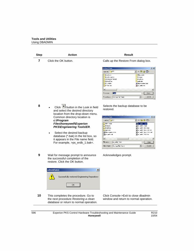
Tools and UtilitiesUsing DBADMIN
596 Experion PKS Control Hardware Troubleshooting and Maintenance Guide R210Honeywell 10/04
Step Action Result
7 Click the OK button. Calls up the Restore From dialog box.
8 • Click button in the Look in fieldand select the desired directorylocation from the drop-down menu.Common directory location isc:\ProgramFiles\honeywell\ExperionPKS\Engineering Tools\ER.
• Select the desired backupdatabase (*.bak) in the list box, soit appears in the File name field.For example, >ps_erdb_1.bak<.
Selects the backup database to berestored.
9 Wait for message prompt to announcethe successful completion of therestore. Click the OK button.
Acknowledges prompt.
10 This completes the procedure. Go tothe next procedure Restoring a cleandatabase or return to normal operation.
Click Console->Exit to close dbadminwindow and return to normal operation.

Tools and UtilitiesUsing DBADMIN
R210 Experion PKS Control Hardware Troubleshooting and Maintenance Guide 59710/04 Honeywell
Restoring “clean” database
Use the following procedure to restore the “clean” database that is provided with theExperion PKS Engineering Tools software. This procedure assumes that you have startedthe DBADMIN utility as outlined in the previous Startup section.
ATTENTION
Disconnect all clients before initiating a database restore function.
ATTENTION
Loss of View: While following restoration/recover procedures for Primarydatabase and Secondary database, there will be a temporary loss of view toboth servers. View will be back once the servers are restarted, approximatelyone minute.
Failover: If the recovery is performed on Server B without losing theharddrive, PC or powering it off, then upon database recovery on Server B,Server A will also fail over to Server B. This is to ensure both SRs are inSync after the database recovery process.
Step Action Result
1 Click the sign for the DbAdmin andServer Node (servername) folders.
Expands the directory tree.
2 Click the ERDB Admin Tasks folder. Calls up ERDB Admin Tasks in the viewpane.
3 Are you using a redundant Server? If the answer is Yes, go to the next Step.
If the answer is No, go to Step 6.
4 Be sure you are logged onto the Serverwith the Primary database.
Want to restore the clean database asthe Design Master (Primary) database.
5 Click the Disable Replication icon. Stops the replication function.
6 Click the Initialize Database icon. Prompt asks if replication is disabled andif you want to continue.
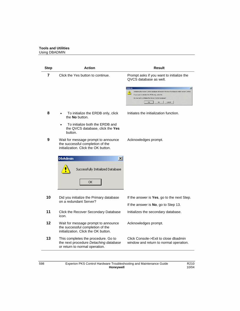
Tools and UtilitiesUsing DBADMIN
598 Experion PKS Control Hardware Troubleshooting and Maintenance Guide R210Honeywell 10/04
Step Action Result
7 Click the Yes button to continue. Prompt asks if you want to initialize theQVCS database as well.
8 • To initialize the ERDB only, clickthe No button.
• To initialize both the ERDB andthe QVCS database, click the Yesbutton.
Initiates the initialization function.
9 Wait for message prompt to announcethe successful completion of theinitialization. Click the OK button.
Acknowledges prompt.
10 Did you initialize the Primary databaseon a redundant Server?
If the answer is Yes, go to the next Step.
If the answer is No, go to Step 13.
11 Click the Recover Secondary Databaseicon.
Initializes the secondary database.
12 Wait for message prompt to announcethe successful completion of theinitialization. Click the OK button.
Acknowledges prompt.
13 This completes the procedure. Go tothe next procedure Detaching databaseor return to normal operation.
Click Console->Exit to close dbadminwindow and return to normal operation.

Tools and UtilitiesUsing DBADMIN
R210 Experion PKS Control Hardware Troubleshooting and Maintenance Guide 59910/04 Honeywell
Detaching database
Use the following procedure to detach and copy the database file to a specified location.This procedure assumes that you have started the DBADMIN utility as outlined in theprevious Startup section.
ATTENTION
Disconnect all clients before detaching a database.
Step Action Result
1 Click the sign for the DbAdmin andServer Node (servername) folders.
Expands the directory tree.
2 Click the ERDB Admin Tasks folder. Calls up ERDB Admin Tasks in the viewpane.
3 Click the Detach Database icon. Prompt asks if you want to continue.
4 Click the Yes button. Initiates the function that stops databaseservices, detaches the database, copiesfiles ps_erdb.mdf and ps_erdb_log.idf tothe c:\Temp directory, re-attaches thedatabase, and starts database services.
5 Wait for prompt to announce successfulcompletion of the operation. Click theOK button.
Acknowledges prompt.

Tools and UtilitiesUsing DBADMIN
600 Experion PKS Control Hardware Troubleshooting and Maintenance Guide R210Honeywell 10/04
Step Action Result
6 This completes the procedure. Go tothe next procedure Expandingdatabase or return to normal operation.
Click Console->Exit to close dbadminwindow and return to normal operation.
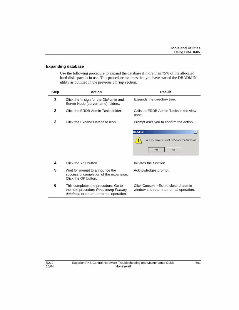
Tools and UtilitiesUsing DBADMIN
R210 Experion PKS Control Hardware Troubleshooting and Maintenance Guide 60110/04 Honeywell
Expanding database
Use the following procedure to expand the database if more than 75% of the allocatedhard-disk space is in use. This procedure assumes that you have started the DBADMINutility as outlined in the previous Startup section.
Step Action Result
1 Click the sign for the DbAdmin andServer Node (servername) folders.
Expands the directory tree.
2 Click the ERDB Admin Tasks folder. Calls up ERDB Admin Tasks in the viewpane.
3 Click the Expand Database icon. Prompt asks you to confirm the action.
4 Click the Yes button. Initiates the function.
5 Wait for prompt to announce thesuccessful completion of the expansion.Click the OK button.
Acknowledges prompt.
6 This completes the procedure. Go tothe next procedure Recovering Primarydatabase or return to normal operation.
Click Console->Exit to close dbadminwindow and return to normal operation.

Tools and UtilitiesUsing DBADMIN
602 Experion PKS Control Hardware Troubleshooting and Maintenance Guide R210Honeywell 10/04
Recovering Primary database
Use the following procedure to recover a Primary database in a redundant Serverapplication only. This procedure assumes that you have started the DBADMIN utility asoutlined in the previous Startup section on the redundant Server running the Primarydatabase.
ATTENTION
Disconnect all clients before initiating a database recovery function.
ATTENTION
Loss of View: While following restoration/recover procedures for Primarydatabase and Secondary database, there will be a temporary loss of view toboth servers. View will be back once the servers are restarted, approximatelyone minute.
Failover: If the recovery is performed on Server B without losing theharddrive, PC or powering it off, then upon database recovery on Server B,Server A will also fail over to Server B. This is to ensure both SRs are inSync after the database recovery process.
Step Action Result
1 Click the Start button in the taskbar.Click Settings->Control Panel
Opens Control Panel window.
2 Double-click Administrative Tools folder
.
Opens Administrative Tools window
3 Double-click Services icon . Opens Services window.

Tools and UtilitiesUsing DBADMIN
R210 Experion PKS Control Hardware Troubleshooting and Maintenance Guide 60310/04 Honeywell
Step Action Result
4 Scroll the list box to find the ExperionPKS System Repository service.Double-click this service.
Opens the Experion PKS SystemRepository Properties dialog box.
5 Click the Stop button. Initiates service shutdown.
6 Wait for service status to change tostopped. Click the OK button.
Closes the dialog box.
7 Close the Services, AdministrativeTools, and Control Panel windows.
Completes tasks.
8 In dbadmin window, click the sign forthe DbAdmin and Server Node(servername) folders.
Expands the directory tree.
9 Click the ERDB Admin Tasks folder. Calls up ERDB Admin Tasks in the viewpane.
10 Click the Recover Primary Databaseicon.
Prompt asks if you want to continue.
11 Click the Yes button. Initiates function to backup theSecondary database and use it to restorethe Primary database.
Tools and UtilitiesUsing DBADMIN
604 Experion PKS Control Hardware Troubleshooting and Maintenance Guide R210Honeywell 10/04
Step Action Result
12 Wait for prompt to announce thesuccessful completion of the action.Click the OK button.
Acknowledges prompt.
13 Repeat Steps 1 to 8, modifying Step 5to click the Start button.
Starts Experion PKS database services.
14 This completes the procedure. Go tothe next procedure RecoveringSecondary database or return to normaloperation.
Click Console->Exit to close dbadminwindow and return to normal operation.

Tools and UtilitiesUsing DBADMIN
R210 Experion PKS Control Hardware Troubleshooting and Maintenance Guide 60510/04 Honeywell
Recovering Secondary database
Use the following procedure to recover a Primary database in a redundant Serverapplication only. This procedure assumes that you have started the DBADMIN utility asoutlined in the previous Startup section on the redundant Server running the Primarydatabase.
ATTENTION
Disconnect all clients before initiating a database recovery function.
ATTENTION
Loss of View: While following restoration/recover procedures for Primarydatabase and Secondary database, there will be a temporary loss of view toboth servers. View will be back once the servers are restarted, approximatelyone minute.
Failover: If the recovery is performed on Server B without losing theharddrive, PC or powering it off, then upon database recovery on Server B,Server A will also fail over to Server B. This is to ensure both SRs are inSync after the database recovery process.
Step Action Result
1 Click the Start button in the taskbar.Click Settings->Control Panel
Opens Control Panel window.
2 Double-click Administrative Tools folder
.
Opens Administrative Tools window
3 Double-click Services icon . Opens Services window.

Tools and UtilitiesUsing DBADMIN
606 Experion PKS Control Hardware Troubleshooting and Maintenance Guide R210Honeywell 10/04
Step Action Result
4 Scroll the list box to find the ExperionPKS System Repository service.Double-click this service.
Opens the Experion PKS SystemRepository Properties dialog box.
5 Click the Stop button. Initiates service shutdown.
6 Wait for service status to change tostopped. Click the OK button.
Closes the dialog box.
7 Close the Services, AdministrativeTools, and Control Panel windows.
Completes tasks.
8 In dbadmin window, click the sign forthe DbAdmin and Server Node(servername) folders.
Expands the directory tree.
9 Click the ERDB Admin Tasks folder. Calls up ERDB Admin Tasks in the viewpane.
10 Click the Recover Secondary Databaseicon.
Prompt asks if you want to continue.
11 Click the Yes button. Initiates function to backup the Primarydatabase and use it to restore theSecondary database.

Tools and UtilitiesUsing DBADMIN
R210 Experion PKS Control Hardware Troubleshooting and Maintenance Guide 60710/04 Honeywell
Step Action Result
12 Wait for prompt to announce thesuccessful completion of the action.Click the OK button.
Acknowledges prompt.
13 Repeat Steps 1 to 8, modifying Step 5to click the Start button.
Starts Experion PKS database services.
14 This completes the procedure. Go tothe next procedure Enabling replicationor return to normal operation.
Click Console->Exit to close dbadminwindow and return to normal operation.
Tools and UtilitiesUsing DBADMIN
608 Experion PKS Control Hardware Troubleshooting and Maintenance Guide R210Honeywell 10/04
Enabling replication
Use the following procedure to initiate the replication function in a redundant Serverapplication only. This procedure assumes that you have started the DBADMIN utility asoutlined in the previous Startup section on the redundant Server running the Primarydatabase.
Step Action Result
1 Click the sign for the DbAdmin andServer Node (servername) folders.
Expands the directory tree.
2 Click the ERDB Admin Tasks folder. Calls up ERDB Admin Tasks in the viewpane.
3 Click the Recover Secondary Databaseicon.
Prompt asks if you want to continue.
4 Click the Yes button. Initiates function to backup the Primarydatabase and use it to restore theSecondary database. This actionsynchronizes the databases inpreparation for replication.
5 Wait for prompt to announce thesuccessful completion of the action.Click the OK button.
Acknowledges prompt.
6 Click the Enable Replication icon. Initiates replication of the database fromthe Primary to the Secondary. It sets upand starts the SQL server jobs to do thereplication.
7 Wait for prompt to announce thesuccessful completion of this operation.Click the OK button.
Acknowledges prompt.
8 This completes the procedure. Go tothe next procedure Disabling replicationor return to normal operation.
Click Console->Exit to close dbadminwindow and return to normal operation.

Tools and UtilitiesUsing DBADMIN
R210 Experion PKS Control Hardware Troubleshooting and Maintenance Guide 60910/04 Honeywell
Disabling replication
Use the following procedure to stop the replication function and delete the configuredreplication setup. This procedure assumes that you have started the DBADMIN utility asoutlined in the previous Startup section on the redundant Server running the Primarydatabase.
Step Action Result
1 Click the sign for the DbAdmin andServer Node (servername) folders.
Expands the directory tree.
2 Click the ERDB Admin Tasks folder. Calls up ERDB Admin Tasks in the viewpane.
3 Click the Disable Replication icon. Prompt asks if you want to continue.
4 Click the Yes button. Stops the replication jobs and deletes theconfigured replication setup.
5 Wait for prompt to announce thesuccessful completion of the action.Click the OK button.
Acknowledges prompt.
6 This completes the procedure. Go tothe next procedure Initiating QVCSdatabase synchronization or return tonormal operation.
Click Console->Exit to close dbadminwindow and return to normal operation.
Initiating QVCS database synchronization and clearing locks
Use the following procedure to synchronize the QVCS database with the ERDB and clearany QVCS locks. This procedure assumes that you have started the DBADMIN utility asoutlined in the previous Startup section.
ATTENTION
It is a good idea to close the Control Builder application while running theDBADMIN utility.
Step Action Result
1 Click the sign for the DbAdmin andServer Node (servername) folders.
Expands the directory tree.

Tools and UtilitiesUsing DBADMIN
610 Experion PKS Control Hardware Troubleshooting and Maintenance Guide R210Honeywell 10/04
Step Action Result
2 Click the VCS Admin Tasks folder. Calls up VCS Admin Tasks in the viewpane.
3 Click the Synchronize VCS icon. Prompt asks if you want to synchronizeVCS database with the ERDB.
4 Click the Yes button. Imitates the synchronization function andclears any VCS locks.
5 Wait for message prompt to announcethe successful completion of thesynchronization. Click the OK button.
Acknowledges prompt.
6 This completes the procedure. Go tothe next procedure Making a backupQVCS database or return to normaloperation.
Click Console->Exit to close dbadminwindow and return to normal operation.
Making a Backup QVCS database
Use the following procedure to make a backup copy of the current QVCS database. Thisprocedure assumes that you have started the DBADMIN utility as outlined in theprevious Startup section.
ATTENTION
It is a good idea to close the Control Builder application while running theDBADMIN utility.
Step Action Result
1 Click the sign for the DbAdmin andServer Node (servername) folders.
Expands the directory tree.
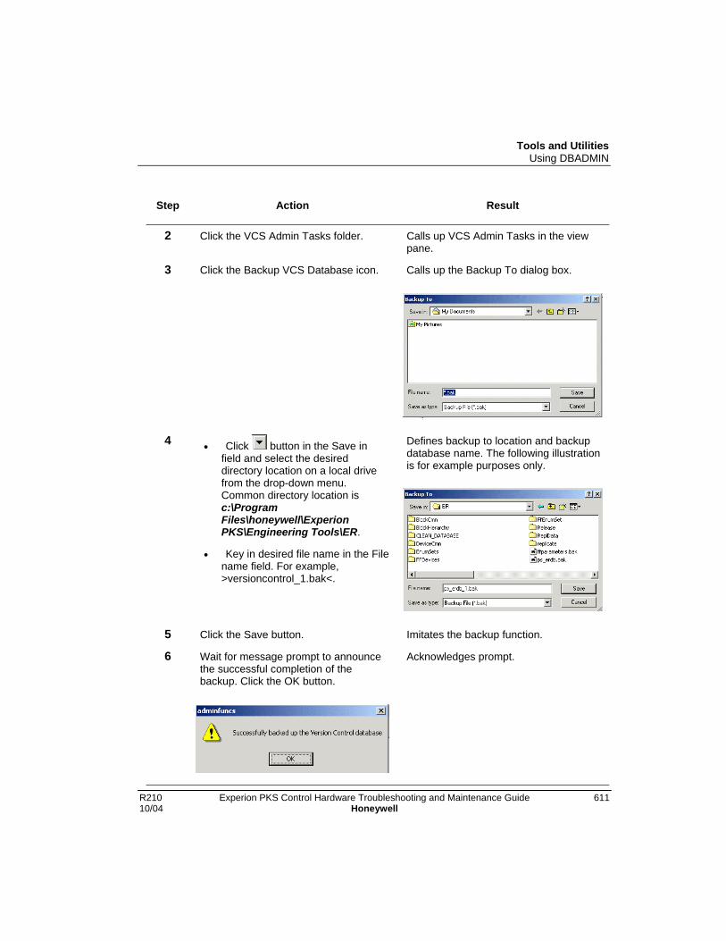
Tools and UtilitiesUsing DBADMIN
R210 Experion PKS Control Hardware Troubleshooting and Maintenance Guide 61110/04 Honeywell
Step Action Result
2 Click the VCS Admin Tasks folder. Calls up VCS Admin Tasks in the viewpane.
3 Click the Backup VCS Database icon. Calls up the Backup To dialog box.
4 • Click button in the Save infield and select the desireddirectory location on a local drivefrom the drop-down menu.Common directory location isc:\ProgramFiles\honeywell\ExperionPKS\Engineering Tools\ER.
• Key in desired file name in the Filename field. For example,>versioncontrol_1.bak<.
Defines backup to location and backupdatabase name. The following illustrationis for example purposes only.
5 Click the Save button. Imitates the backup function.
6 Wait for message prompt to announcethe successful completion of thebackup. Click the OK button.
Acknowledges prompt.

Tools and UtilitiesUsing DBADMIN
612 Experion PKS Control Hardware Troubleshooting and Maintenance Guide R210Honeywell 10/04
Step Action Result
7 This completes the procedure. Go tothe next procedure Restoring a backupQVCS database or return to normaloperation..
Click Console->Exit to close dbadminwindow and return to normal operation.
Restoring a backup QVCS database
Use the following procedure to restore a backup database. This procedure assumes thatyou have started the DBADMIN utility as outlined in the previous Startup section andyou have created a backup database as outlined in the prior procedure.
ATTENTION
Disconnect all clients before initiating a database restore function.
Step Action Result
1 Click the sign for the DbAdmin andServer Node (servername) folders.
Expands the directory tree.
2 Click the VCS Admin Tasks folder. Calls up VCS Admin Tasks in the viewpane.
3 Click the Restore VCS Database icon. Prompt asks if replication is disabled andif you want to continue.

Tools and UtilitiesUsing DBADMIN
R210 Experion PKS Control Hardware Troubleshooting and Maintenance Guide 61310/04 Honeywell
Step Action Result
4 Click the OK button. Calls up the Restore From dialog box.
5 • Click button in the Look in fieldand select the desired directorylocation from the drop-down menu.Common directory location isc:\ProgramFiles\honeywell\ExperionPKS\Engineering Tools\ER.
• Select the desired backupdatabase (*.bak) in the list box, soit appears in the File name field.For example, >versioncontrol.bak<.
Selects the backup database to berestored. The following illustration is forexample purposes only.
6 Wait for message prompt to announcethe successful completion of therestore. Click the OK button.
Acknowledges prompt.
7 This completes the procedure. Go toanother procedure or return to normaloperation.
Click Console->Exit to close dbadminwindow and return to normal operation.
Tools and UtilitiesI/O Maintenance Tool
614 Experion PKS Control Hardware Troubleshooting and Maintenance Guide R210Honeywell 10/04
I/O Maintenance Tool
Overview
The I/O Maintenance Tool allows the user to {1} navigate to a single I/O Module anddisplay Module Information and Status, {2} perform calibration for various AnalogModules, and {3} reset Short/Overload Faults on Diagnostic Output Modules. Theseoperations are separated into 3 tabs on the main I/O Maintenance Tool display:Navigator, Calibration, and Utilities respectively. The Calibration and Utilities tabs arenot accessible until the user specifies the appropriate target I/O Module type on theNavigator tab.
ATTENTION
If your system includes Configuration Studio, you launch the I/O MaintenanceTool through Configuration Explorer by clicking ControlStrategy>Maintain I/O modules.
Navigator Tab
The Navigator Tab is used to specify the location of the I/O Module that requiresmaintenance. The target I/O module can be either a Rack or Rail mount module, and thedestination Rack/Rail can reside on either a Local or Remote network.
Select Driver Used to select an appropriate driver to communicate with thetarget I/O Module. The IO Maintenance Tool supports themaintenance of IO Modules via both Ethernet andControlNet networks. With the possibility of having multipleRSLinx drivers, the user must explicitly select the driverneeded to communicate with the target I/O module. Atstartup, the IO Maintenance Tool populates this combo boxwith a list of configured RSLinx drivers. Please note thatRSLinx drivers must be configured before using the IOMaintenance Tool.
Enable Remote If the target I/O Module resides on a remote network (i.e. notdirectly connected to the PC), check this Box to expose theRemote Network fields.
Rail I/O If selecting a Rail I/O Module, check this box to expose theGateway and Device Information fields. Selecting this boxalso changes the final ‘SLOT' field to 'MODULE #', becauseRail I/O modules are referred to by their number position onthe Rail vs. Rack I/O modules that are referenced by the slotlocation in the Rack.

Tools and UtilitiesI/O Maintenance Tool
R210 Experion PKS Control Hardware Troubleshooting and Maintenance Guide 61510/04 Honeywell
Local Network If the ‘Enable Remote’ check box is selected, the LocalNetwork information specifies the communication hub usedto reach the remote network. Otherwise, if the EnableRemote check box is not selected, the Local Networkinformation specifies the target Rail/Rack I/O module.
Local Network information is comprised of up to 2 fields:‘MAC ID’ and ‘SLOT’. The ‘MAC ID’ field specifies theControlNet address directly connected to this PC. Note thatthis selection is not required and hence not available whenan Ethernet driver has been selected.
The ‘SLOT’ field specifies the Rack position of either the I/OModule (i.e. no remote network) or the communicationinterface module (i.e. I/O Module on remote network). Notethat if the I/O Module resides on the local network and it is aRail I/O Module (i.e. ‘Enable Remote’ is not selected and‘Rail I/O’ is selected), the ‘SLOT’ field is renamed to‘MODULE #’.
Remote Network The Remote Network entry fields are only exposed when theEnable Remote check box is selected. Remote Networkinformation is comprised of 2 fields: {1} ‘MAC ID’ and {2}either ‘SLOT’ in the case of Rack I/O or 'MODULE #' in thecase of Rail I/O. The ‘MAC ID’ field specifies the ControlNetaddress of the remote Rack/Rail. The ‘SLOT’ / ‘MODULE #’field specifies the Rack / Rail position of the I/O Module.Note that the ‘SLOT’ field is only renamed to ‘MODULE #’ ifthe I/O Module is a Rail I/O Module (i.e. ‘Rail I/O’ isselected).

Tools and UtilitiesI/O Maintenance Tool
616 Experion PKS Control Hardware Troubleshooting and Maintenance Guide R210Honeywell 10/04
The following illustration depicts the Navigator Tab configuration for a Rack I/O Moduleresiding on a local ControlNet network.

Tools and UtilitiesI/O Maintenance Tool
R210 Experion PKS Control Hardware Troubleshooting and Maintenance Guide 61710/04 Honeywell
The following illustration depicts the Navigator Tab configuration for a Rack I/O Moduleresiding on a local Ethernet network.

Tools and UtilitiesI/O Maintenance Tool
618 Experion PKS Control Hardware Troubleshooting and Maintenance Guide R210Honeywell 10/04
The following illustration depicts the Navigator Tab configuration for a Rail I/O Moduleresiding on a local ControlNet network. Note that although the equivalent selections fora local Ethernet network are allowed by the I/O Maintenance Tool, this is currently anon-supported topology.
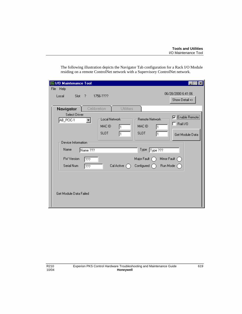
Tools and UtilitiesI/O Maintenance Tool
R210 Experion PKS Control Hardware Troubleshooting and Maintenance Guide 61910/04 Honeywell
The following illustration depicts the Navigator Tab configuration for a Rack I/O Moduleresiding on a remote ControlNet network with a Supervisory ControlNet network.

Tools and UtilitiesI/O Maintenance Tool
620 Experion PKS Control Hardware Troubleshooting and Maintenance Guide R210Honeywell 10/04
The following illustration depicts the Navigator Tab configuration for a Rail I/O Moduleresiding on a remote ControlNet network with a Supervisory Ethernet network.
Selection of the 'GET MODULE DATA' Button causes the I/O Maintenance Tool toacquire information & status for the targeted I/O Module. For Rack I/O, the requestedI/O Module information is displayed in the Device Information field. For Rail I/O, therequested I/O Module information is displayed in the ControlNet Gateway Informationand Device Information fields.
Tools and UtilitiesI/O Maintenance Tool
R210 Experion PKS Control Hardware Troubleshooting and Maintenance Guide 62110/04 Honeywell
For Rack I/O:
Device Information
Name The Catalog name of the I/O Module.
Type The type of I/O Module.
FW Version The version number of the I/O Modulefirmware currently loaded.
Serial Num The I/O Module's serial number.
LEDs The I/O Module Operation and Fault Status isdisplayed by the round "LED" symbols.
For Rail I/O:
ControlNet Gateway Information:
Name The Catalog name of the ControlNet Gateway.
Type The type of ControlNet Gateway.
FW Version The version number of the ControlNetGateway firmware currently loaded.
Serial Num The ControlNet Gateway's serial number.
LEDs The ControlNet Gateway Operation and FaultStatus is displayed by the round "LED"symbols.
Device Information:
Name The Catalog name of the I/O Module.
Type The type of I/O Module.
If this data reflects the desired I/O Module, proceed to the Calibration or Utilities Tabs.
NOTES:
1. Selection of an Analog Module enables the Calibration Tab.
2. Selection of a Diagnostic Output Module enables the Utilities Tab.
3. If 'GET MODULE DATA' fails, some of the fields display '???' and a STATUSmessage is displayed at the bottom of the Navigator Tab.

Tools and UtilitiesI/O Maintenance Tool
622 Experion PKS Control Hardware Troubleshooting and Maintenance Guide R210Honeywell 10/04
4. Possible Messages:
− "Get Module Data Succeeded"
− "Get Module Data Failed"
− "Bad MAC ID for the Remote CNI"
− "Bad SLOT # for the Local Rack CNI""Selected Analog Module is READY to Calibrate"
− "Selected Analog Module is RUNNING. You MUST INACTIVATE and DELETEthis Module from the Control Builder Monitoring TAB before Calibrating."
− "The ControlNet Gateway is Connected to one or more Rail I/O Devices. YouMUST INACTIVATE and DELETE any such Device(s) from the Control BuilderMonitoring TAB before Calibrating."
Calibration Tab
The Calibration Tab is enabled once the Navigator Tab specifies an Analog Module. Thefollowing are procedures for performing a Calibration sequence for various AnalogModules. Substitute calibration values from the procedure-subordinate tables based onthe particular I/O Module type.

Tools and UtilitiesI/O Maintenance Tool
R210 Experion PKS Control Hardware Troubleshooting and Maintenance Guide 62310/04 Honeywell
Analog Input (Rack I/O) Module Calibration
ATTENTION
This calibration procedure only applies to the following Rack I/O Modules:TC-IAH061, TC-IAH161, TC-IXL061, and TC-IXR061.
1. Select the Channel or Channels to be calibrated with the "Select" check boxes next toeach Channel. For TC-IAH161, the "Select Channel Group Box" is also used tonavigate between the four (4) four-channel groups.
2. Select the 'Optional Cal Range' if the calibration range is 1~20mA for TC-IAH061, or-14~30mV for TC-IXL061. Do not check for the other Analog Input module types.
3. Press 'Start Calibration Mode' Button. Calibration is prohibited if the I/O Module is inRUN Mode. Please inactivate and unload (delete) the I/O Module from the Controllerbefore proceeding with Calibration.
4. Input exactly the Low Cal Value to the screw terminals of the channel(s).
5. Press 'Perform Low Cal' Button. The input is then sampled and the 'L' LED transitionsto Yellow. If the Input is out of range the LED transitions to Red and the calibration isunsuccessful. Verify that the input is exactly the Low Cal Value and press 'PerformLow Cal' again.
6. Once the 'L' LED is Yellow, input exactly the High Cal Value to the screw terminalsof the channel(s).
7. Press 'Perform High Cal' Button. The input is then sampled and the 'H' LED shouldtransition to Yellow. If the Input is out of range the LED transitions to Red and thecalibration is unsuccessful. Verify that the input is exactly the High Cal Value andpress 'Perform High Cal' again.
8. Now that the Low signal and High signal are sampled, the calibration should finishand the 'H' and 'L' LEDs transition to Green. The Calibration Status LED on the leftalso transitions to Green. If either the low or high signal is not sampled correctly, thecalibration is unsuccessful. In that case you can stop the calibration by pressing the'Stop Calibration Mode' button. Note that the Calibration Status LED transitions toRed.
9. When the calibration has succeeded, the calibration mode stops automatically. You donot need to press 'Stop Calibration Mode' button. If you need to continue thecalibration for other channels, repeat from step 1) until all channels are calibratedcorrectly.

Tools and UtilitiesI/O Maintenance Tool
624 Experion PKS Control Hardware Troubleshooting and Maintenance Guide R210Honeywell 10/04
Analog Input (Rack I/O) Calibration Value Table
Module Low Value Low Tolerance High Value High Tolerance
TC-IAH061 0V +/-0.68mV +10V +/-0.6V
(Optional range) 1mA 20mA
TC-IAH161 0V +/-0.11V +10.25 -0.07~0.18V
TC-IXL061 -12mV -0.89~0.84mV +78mV -3.7~4.0mV
(Optional range) -14.22mV +30.78mV
TC-IXR061 1 Ohm +/-0.8 Ohm 487 Ohm +/-17 Ohm
Notes:
• TC-IXL061 and TC-IAH061 have two types of Calibration values depending on theconfiguration.
• The type is selected by the "Optional Cal Range" check box.
• The tolerance for -14~30mV type is half of the -12~78 type.
• The tolerance means allowable difference counts from the Nominal Counts before thevalue is rejected with an error.
• The counts are converted to physical value based on the High Cal Nominal counts.
• The accuracy of the devices are typically 0.005%.

Tools and UtilitiesI/O Maintenance Tool
R210 Experion PKS Control Hardware Troubleshooting and Maintenance Guide 62510/04 Honeywell
Analog Output (Rack I/O) Module Calibration
ATTENTION
This calibration procedure only applies to the following Rack I/O Modules:TC-OAV061, TC-OAH061, and TC-OAV081.
1. Select the Channel or Channels to be calibrated with the "select" check boxes next toeach Channel. For TC-OAV061, the "Select Channel Group Box" is also used tonavigate between the two (2) four-channel groups.
2. For TC-OAV081, the "optional cal range" selection enables the channel(s) selected tooutput mA values to the current output pins, for Current Mode calibration.
3. Press 'Start Calibration Mode' Button
4. Press 'Perform Low Cal' Button. The AO module outputs the Low Value. The 'L'LED transitions to Yellow.
5. Measure the value of the screw, and enter the value into the left 'Measurements' textbox.
6. Press 'Perform High Cal' Button. The AO module outputs the High Value, and the 'H'LED transitions to Yellow.
7. Measure the value of the screw, and enter the value into the right 'Measurements' textbox. The value should be near the High Value.
8. Press 'Finish Calibration' Button. The calibration should finish. If the entered valuesare out of range, the calibration is unsuccessful. In that case you can stop thecalibration by pressing the 'Stop Calibration Mode' button. Note that the CalibrationStatus LED transitions to Red.
9. When the calibration has succeeded, the calibration mode stops automatically. You donot need to press 'Stop Calibration Mode' button. If you need to continue thecalibration for other channels, repeat from step 1).

Tools and UtilitiesI/O Maintenance Tool
626 Experion PKS Control Hardware Troubleshooting and Maintenance Guide R210Honeywell 10/04
Analog Output (Rack I/O) Calibration Value Table
Module Low Value Low Tolerance High Value High Tolerance
TC-OAV061 0.0 V +/-18 mV 10.0 V +/-251 mV
TC-OAH061 4.0 mA +/-0.15 mA 20.0 mA +/-0.67 mA
TC-OAV081 0.0 V +/-18 mV 10.0 V +/-251 mV
(Optionalcurrent range)
4.0 mA +/-0.15 mA 20.0 mA +/-0.67 mA
Notes:
• When the calibration has finished, the 'Last Cal Date' in the module is updated toToday's date.
Current Input (Rail I/O) Module Calibration
ATTENTION
This procedure only applies to TC-PIA082. The TC-FIAH81 does not allowcalibration.
1. Select a Channel to be calibrated with the "Select" check boxes next to the ChannelNumber. You can also select 'Sel All' to calibrate all channels at the same time.
2. Press 'Start Calibration Mode' Button. Calibration is prohibited if the Module is inRUN Mode. Please inactivate and unload (delete) the Module from the Controllerbefore proceeding with Calibration. If the calibration can proceed, the 'Cal Active'LED on the top left corner transitions to Green.
3. Create an open circuit between the 'sig' (+) terminal and '-' (-) terminal(s) of selectedchannel(s).

Tools and UtilitiesI/O Maintenance Tool
R210 Experion PKS Control Hardware Troubleshooting and Maintenance Guide 62710/04 Honeywell
4. Press 'Offset Cal' Button. The Input is then sampled and the 'Offset' LED(s) shouldtransition to Green. If the Input is out of range, the LED(s) transition to Red. In thiscase the calibration did not succeed. Verify that there is an open circuit between 'sig'(+) terminal and '-' (-) terminal(s) of selected channel(s) and press 'Offset Cal' again.
5. Once the 'Offset' LED(s) transition to Green, input exactly the Gain Calibration Valueof 20.000 mA to the screw terminals of the channel(s).
6. Press 'Gain Cal' Button. The Input is then sampled and the 'Gain' LED(s) shouldtransition to Green. If the Input is out of range the LED(s) transition to Red. In thiscase the calibration did not succeed. Verify that the current source connection iscorrect and that the input is exactly the Gain Calibration Value and press 'Gain Cal'again.
7. Once the Offset and Gain signals are sampled, the calibration should finish and the'Offset' and 'Gain' LEDs should be Green.
8. If you need to continue the calibration for other channels, repeat from step 1) until allchannels are calibrated correctly.
9. When the calibration has succeeded, press 'Stop Calibration Mode' button. All LEDstransition to White and the Navigator Tab is enabled.
Notes:
• The accuracy of current source should be 0.01% or better.
• Current Input Channels should not be connected in parallel to one source. Individualcurrent sources must be used or channels must be calibrated on at a time.

Tools and UtilitiesI/O Maintenance Tool
628 Experion PKS Control Hardware Troubleshooting and Maintenance Guide R210Honeywell 10/04
Current Output (Rail I/O) Module Calibration
ATTENTION
This procedure only applies to TC-POA082. The TC-FOA041 does not allowcalibration.
1. Select a Channel to be calibrated with the "Select" check box next to the ChannelNumber. You can also select 'Sel All' to calibrate all channels at the same time.
2. Press 'Start Calibration Mode' Button. Calibration is prohibited if the Module is inRUN Mode. Please inactivate and unload (delete) the Module from the Controllerbefore proceeding with Calibration. If the calibration can proceed, the 'Cal Active'LED on the top left corner transitions to Green.
3. Press 'Min Scale Cal' Button. The AO module outputs the Min Scale Cal Ref value of1.000 mA. The 'Min' LED transitions to Yellow.
4. Connect the '+' lead(s) of the current meter(s) to the '+' terminal(s) of selectedChannel(s). Connect the '-' lead(s) of the current meter(s) to 250 Ohm resistor(s).Connect the other end(s) of the 250 Ohm resistor(s) to the '-' terminal(s) of selectedChannel(s).
5. Measure the value(s) at the screw(s), and enter the value(s) into the left'Measurements' text box to a precision of 0.001 mA.
6. Press 'Finish Calibration' Button. The Minimum Scale calibration should finish andthe 'Min' Calibration Status LED(s) transition to Green. If the entered value(s) are outof range, the calibration is unsuccessful and the 'Min' Calibration Status LED(s)transition to Red. Verify that the current meter(s) are properly connected and press'Min Scale Cal' Button again.
7. Press 'Max Scale Cal' Button. The AO module outputs the Max Scale Cal Ref value of21.000 mA. The 'Max' LED transitions to Yellow.
8. Connect the '+' lead(s) of the current meter(s) to the '+' terminal(s) of selectedChannel(s). Connect the '-' lead(s) of the current meter(s) to 250 Ohm resistor(s).Connect the other end(s) of the 250 Ohm resistor(s) to the '-' terminal(s) of selectedChannel(s).
9. Measure the value(s) of the screw(s), and enter the value(s) into the left'Measurements' text box to a precision of 0.001 mA.

Tools and UtilitiesI/O Maintenance Tool
R210 Experion PKS Control Hardware Troubleshooting and Maintenance Guide 62910/04 Honeywell
10. Press 'Finish Calibration' Button. The Maximum Scale calibration should finishand the 'Max' Calibration Status LED(s) transition to Green. If the entered value(s) areout of range, the calibration is unsuccessful and the 'Max' Calibration Status LED(s)transition to Red. Verify that the current meter(s) are properly connected and press'MaxScale Cal' Button again.
11. If you need to continue the calibration for other channels, repeat from step 1)until all channels are calibrated correctly.
12. When the calibration has succeeded, press 'Stop Calibration Mode' button.
Notes:
• The accuracy of current source should be 0.01% or better.

Tools and UtilitiesI/O Maintenance Tool
630 Experion PKS Control Hardware Troubleshooting and Maintenance Guide R210Honeywell 10/04
Temperature Input (Rail I/O) Module Calibration #1
ATTENTION
There are two Temperature Input (Rail I/O) Module calibration procedures.This procedure only applies to TC-PIL081. There is a separate procedure(following this one) for TC-FIL081.
1. Select a Channel to be calibrated with the "Select" check box next to the ChannelNumber. You can also select 'Sel All' to calibrate all channels at the same time.
2. Press 'Start Calibration Mode' Button. Calibration is prohibited if the Module is inRUN Mode. Please inactivate and unload (delete) the Module from the Controllerbefore proceeding with Calibration. If the calibration can proceed, the 'Cal Active'LED on the top left corner transitions to Green.
3. Press 'Offset Cal' Button. This enables Offset calibration for ALL Programmable GainAmplifier (PGA) Selections.
4. Connect the voltage source to the millivolt-input terminals of the selected Channel(s).
5. To the screw terminals of the selected channel(s), input exactly the Offset CalibrationValue for a particular PGA Selection for which a button is currently Enabled. (Note:Refer to the table below for Offset Calibration Values corresponding to each PGASelection). Press the Enabled PGA Selection Button. The Input is then sampled andthe 'Offset' LED(s) should transition to Green. If the Input is out of range, the LED(s)transition to Red. In this case the calibration did not succeed. Verify that the voltagesource connection is correct and that the input is exactly the specified OffsetCalibration Value and press Enabled PGA Selection Button again. Repeat this step forall PGA Selections.
6. Press 'Gain Cal' Button. This enables Gain calibration for ALL PGA Selections.
7. To the screw terminals of the selected channel(s), input exactly the Gain CalibrationValue for a particular PGA Selection for which a button is currently Enabled. (Note:Refer to the table below for Gain Calibration Values corresponding to each PGASelection). Press the Enabled PGA Selection Button. The Input is then sampled andthe 'Gain' LED(s) should transition to Green. If the Input is out of range, the LED(s)transition to Red. In this case the calibration did not succeed. Verify that the voltagesource connection is correct and that the input is exactly the specified Gain CalibrationValue and press Enabled PGA Selection Button again. Repeat this step for all PGASelections.

Tools and UtilitiesI/O Maintenance Tool
R210 Experion PKS Control Hardware Troubleshooting and Maintenance Guide 63110/04 Honeywell
8. Connect 383 Ohm resistor(s) to the selected channel(s) in a 4 wire configuration(resistor is connected to '+' and '–' terminals, and sense wire is connected to 'L' and 'H'terminals).
9. Press '383 Ohm Current Cal' Button. The Input is then sampled and the '383�' LED(s)should transition to Green. If the resistor value is wrong or the connection is notcorrect, the LED(s) transition to Red. In this case the calibration did not succeed.Verify that the resistor value is exactly the specified value and is properly connected ina 4-wire configuration and press '383 Ohm Current Cal' Button again.
10. Connect 100 Ohm resistor(s) to the selected channel(s) in a 4 wireconfiguration.
11. Press '100 Ohm Current Cal' Button. The Input is then sampled and the '100�'LED(s) should transition to Green. If the resistor value is wrong or the connection isnot correct, the LED(s) transition to Red. In this case the calibration did not succeed.Verify that the resistor value is exactly the specified value and is properly connected ina 4-wire configuration and press '100 Ohm Current Cal' Button again.
12. Select Thermistor(s) for Cold Junction Compensation calibration. Replace theselected cold junction compensation thermistor(s) by a 10K Ohm resistor(s).
13. Press 'Cold Junction Compensation Calibration' Button. The LED(s) next to theselected thermistor(s) should transition to Green. If the resistor(s) value is wrong, theLED(s) transition to Red. In this case the calibration did not succeed. Verify that theresistor value is exactly the specified value and it is properly connected in a 4-wireconfiguration and press 'Cold Junction Compensation Calibration' Button again.
14. If you need to continue the calibration for other channels or thermistors, repeatfrom step 1) until all channels and thermistors are calibrated correctly.
15. When the calibration has succeeded, press 'Stop Calibration Mode' button. AllLEDs transition to White and the Navigator Tab becomes enabled.
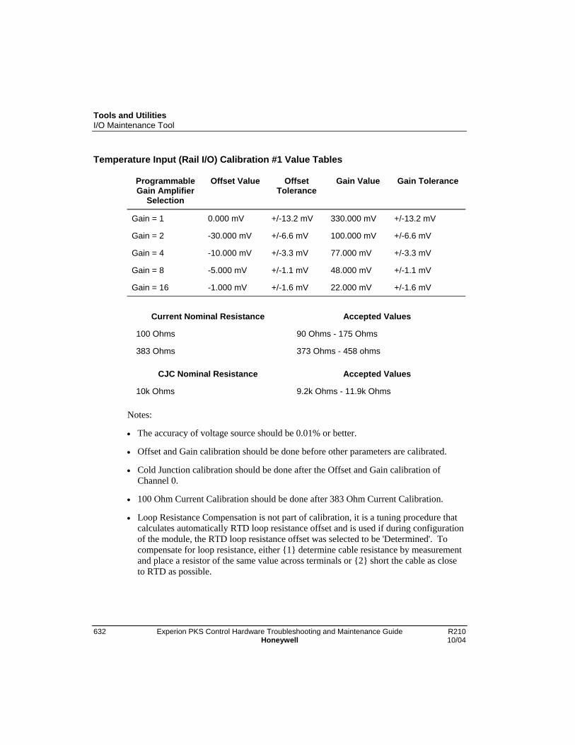
Tools and UtilitiesI/O Maintenance Tool
632 Experion PKS Control Hardware Troubleshooting and Maintenance Guide R210Honeywell 10/04
Temperature Input (Rail I/O) Calibration #1 Value Tables
ProgrammableGain Amplifier
Selection
Offset Value OffsetTolerance
Gain Value Gain Tolerance
Gain = 1 0.000 mV +/-13.2 mV 330.000 mV +/-13.2 mV
Gain = 2 -30.000 mV +/-6.6 mV 100.000 mV +/-6.6 mV
Gain = 4 -10.000 mV +/-3.3 mV 77.000 mV +/-3.3 mV
Gain = 8 -5.000 mV +/-1.1 mV 48.000 mV +/-1.1 mV
Gain = 16 -1.000 mV +/-1.6 mV 22.000 mV +/-1.6 mV
Current Nominal Resistance Accepted Values
100 Ohms 90 Ohms - 175 Ohms
383 Ohms 373 Ohms - 458 ohms
CJC Nominal Resistance Accepted Values
10k Ohms 9.2k Ohms - 11.9k Ohms
Notes:
• The accuracy of voltage source should be 0.01% or better.
• Offset and Gain calibration should be done before other parameters are calibrated.
• Cold Junction calibration should be done after the Offset and Gain calibration ofChannel 0.
• 100 Ohm Current Calibration should be done after 383 Ohm Current Calibration.
• Loop Resistance Compensation is not part of calibration, it is a tuning procedure thatcalculates automatically RTD loop resistance offset and is used if during configurationof the module, the RTD loop resistance offset was selected to be 'Determined'. Tocompensate for loop resistance, either {1} determine cable resistance by measurementand place a resistor of the same value across terminals or {2} short the cable as closeto RTD as possible.

Tools and UtilitiesI/O Maintenance Tool
R210 Experion PKS Control Hardware Troubleshooting and Maintenance Guide 63310/04 Honeywell
Temperature Input (Rail I/O) Module Calibration #2
ATTENTION
There are two Temperature Input (Rail I/O) Module calibration procedures.This procedure only applies to TC-FIL081. The previous procedure applies toTC-PIL081.
1. Select a Channel to be calibrated with the "Select" check box next to the ChannelNumber. You can also select 'Sel All' to calibrate all channels at the same time.
2. Press 'Start Calibration Mode' Button. Calibration is prohibited if the Module is inRUN Mode. Please inactivate and unload (delete) the Module from the Controllerbefore proceeding with Calibration. If the calibration can proceed, the 'Cal Active'LED on the top left corner transitions to Green.
3. Connect 0.000mV across each input channel. Connect all high signal terminalstogether and attach to the positive lead from the precision voltage source. Connect alllow signal terminals together and attach to the negative lead. The Offset CalibrationValue is 0.000mV.
4. Press 'Offset Cal' Button. This enables Offset calibration for the selected channel(s).
5. The Input is then sampled and the 'Offset' LED(s) should transition to Green. If theInput is out of range, the LED(s) transition to Red. In this case the calibration did notsucceed. Verify that the voltage source connection is correct and that the input isexactly the specified Offset Calibration Value.
6. If the Offset Calibration was successful, then proceed to the Gain Calibration.Connect exactly 75.000mV (the Gain Calibration Value) across each input channel.
7. Press 'Gain Cal' Button. This enables Gain calibration for the selected channel(s).
8. The Input is then sampled and the 'Gain' LED(s) should transition to Green. If theInput is out of range, the LED(s) transition to Red. In this case the calibration did notsucceed. Verify that the voltage source connection is correct and that the input isexactly the specified Gain Calibration Value.
9. If you need to continue the calibration for other channels, repeat from step 1) until allchannels are calibrated correctly.
10. When the calibration has succeeded, press 'Stop Calibration Mode' button. AllLEDs transition to White and the Navigator Tab becomes enabled.
Tools and UtilitiesI/O Maintenance Tool
634 Experion PKS Control Hardware Troubleshooting and Maintenance Guide R210Honeywell 10/04
RTD Input (Rail I/O) Module Calibration
ATTENTION
This procedure only applies to TC-FIR081.
1. Select a Channel to be calibrated with the "Select" check box next to the ChannelNumber. You can also select 'Sel All' to calibrate all channels at the same time.
2. Press 'Start Calibration Mode' Button. Calibration is prohibited if the Module is inRUN Mode. Please inactivate and unload (delete) the Module from the Controllerbefore proceeding with calibration. If the calibration can proceed, the 'Cal Active'LED on the top left corner transitions to Green.
3. Connect 1.00 ohm resistors across each input channel. Connect the low signal side to24Vdc common. If using a decade box, connect all high signal terminals together andattach to one lead from the decade box. Connect all low signal terminals together andattach to the other lead and to 24V dc common. Set the decade box for 1.00 ohm. TheOffset Calibration Value is 1.00 ohm.
4. Press 'Offset Cal' Button. This enables Offset calibration for the selected channel(s).
5. The Input is then sampled and the 'Offset' LED(s) should transition to Green. If theInput is out of range, the LED(s) transition to Red. In this case the calibration did notsucceed. Verify that the voltage source connection is correct and that the input isexactly the specified Offset Calibration Value.
6. If the Offset Calibration was successful, then proceed to Selecting the RTD type forthe Gain Calibration. Use the table below to determine the Gain Calibration.
7. Connect the correct resistors across each input channel. Connect the low signal side to24V dc common. Resistor values are shown in the table below. If using a decade box,connect all high signal terminals together and attach to one lead from the decade box.Connect all low signal terminals together and attach to the other lead and to 24V dccommon. Set the decade box for the value shown in the table below.
8. Press 'Gain Cal' Button. This enables Gain calibration for the selected channel(s).
9. The Input is then sampled and the 'Gain' LED(s) should transition to Green. If theInput is out of range, the LED(s) transition to Red. In this case the calibration did notsucceed. Verify that the voltage source connection is correct and that the input isexactly the specified Gain Calibration Value.
10. If you need to continue the calibration for other channels, repeat from step 1)until all channels are calibrated correctly.

Tools and UtilitiesI/O Maintenance Tool
R210 Experion PKS Control Hardware Troubleshooting and Maintenance Guide 63510/04 Honeywell
11. When the calibration has succeeded, press 'Stop Calibration Mode' button. AllLEDs transition to White and the Navigator Tab becomes enabled.
RTD Input (Rail I/O) Calibration Value Table
Type of RTD Offset Calibration Value Gain Calibration Value
100 ohm Pt.(alpha = 0.00385)
1 ohm, 0.1%, 5ppm/deg C
100 ohm Pt.(alpha = 0.003916)
1 ohm, 0.1%, 5ppm/deg C 432ohm, 0.01%, 5ppm/deg C
120 ohm Nickel(alpha = 0.00672)
1 ohm, 0.1%, 5ppm/deg C 432ohm, 0.01%, 5ppm/deg C
100 ohm Nickel(alpha = 0.00618)
1 ohm, 0.1%, 5ppm/deg C 432ohm, 0.01%, 5ppm/deg C
10 ohm Copper(alpha = 0.00427)
1 ohm, 0.1%, 5ppm/deg C 432ohm, 0.01%, 5ppm/deg C
200 ohm Pt.(alpha = 0.00385)
1 ohm, 0.1%, 5ppm/deg C 864 ohm, 0.01%, 5ppm/deg C
200 ohm Nickel(alpha = 0.00618)
1 ohm, 0.1%, 5ppm/deg C 864 ohm, 0.01%, 5ppm/deg C
500 ohm Pt.(alpha = 0.00385)
1 ohm, 0.1%, 5ppm/deg C 1728 ohm, 0.01%, 5ppm/deg C
500 ohm Nickel(alpha = 0.00618)
1 ohm, 0.1%, 5ppm/deg C

Tools and UtilitiesI/O Maintenance Tool
636 Experion PKS Control Hardware Troubleshooting and Maintenance Guide R210Honeywell 10/04
Utilities Tab
The Utilities Tab is enabled once a Diagnostic Output Module is selected in theNavigator Tab. The Utilities Tab is used to reset Diagnostic Output Module SHORT /THERMAL OVERLOAD Faults as follows:
1. Be sure that the condition, which caused the Short/Overload, has been corrected.
2. Enable the Channel or Channels to be reset with the 'Enable Reset' check boxes.
CAUTION
Only Shorted Channels should be Enabled. Resetting Outputs that are "ON"and NOT shorted will cause transition to the "OFF" (Unpowered) State.
3. Press the RESET COMMAND Button.
4. A RESET COMMAND WARNING Message Box will appear. This reminds the Userto confirm that Only Shorted Channels should be Enabled.
5. Press 'YES' if ready to Send the Command or 'NO' if you wish to change any ResetEnable selections before sending the Command.
6. When the Command is sent, the Fault condition should be cleared for the Channel(s)selected as indicated by {1} the I/O Module Detail Display on STATION, {2} the I/OChannel Function Block in Control Builder, or {3} the LED status on the front of theI/O Module.
Tools and UtilitiesNetworkTools
R210 Experion PKS Control Hardware Troubleshooting and Maintenance Guide 63710/04 Honeywell
NetworkTools
Overview
NetworkTools automatically starts up by scanning all nodes on the ControlNet, Ethernet,or Fault Tolerant Ethernet (FTE) supervisory network segment connected to yourcomputer. Information is presented in three panes - the Tree pane (on the upper left), theList pane (on the upper right) and, below them, the Detail pane. The List pane showsControlNet message error counters maintained by NetworkTools. Consult the Help filefor NetworkTools (from the application’s menu bar or hit F1) for on-line Help.
Cautions
CAUTION
Honeywell makes the following recommendation:
NetworkTools is a utility. Under abnormal network conditions, this utility maynegatively impact network performance.
• Do not use NetworkTools while connecting nodes to the network.
• Do not use NetworkTools when monitoring an Analog I/O Module.
• Do not use NetworkTools to monitor an Analog I/O ControlNet.
• Do not use NetworkTools while On Control.
Consider running NetworkTools with the Pause / Resume mode of operation or usingPing mode if you plan to engage in any of the above activities. This way you can letNetworkTools remain launched while performing such activities.

Tools and UtilitiesNetworkTools
638 Experion PKS Control Hardware Troubleshooting and Maintenance Guide R210Honeywell 10/04
Command Line options
NetworkTools supports several command-line options. Start NetworkTools at thecommand prompt with the command-line options as follows:
ATTENTION
If your system includes Configuration Studio, you set the command lineoptions pg, pit, l, nl, and u through the corresponding check box selections onthe Select options for Network Tools dialog. On Configuration Explorer,click Control Strategy>Set options for maintaining control systemfirmware to call up the dialog.
Option Behavior
ntools -c Starts the NetworkTools application in the ControlNet mode. Thismeans NetworkTools scans for MAC IDs on a supervisoryControlNet segment through the ControlNet Driver. If there is morethan one ControlNet Driver installed, the NetworkTools applicationuses the first available driver. NetworkTools displays the MAC IDspresent in the tree pane.
ntools -e Starts the NetworkTools application in the Ethernet mode. Thismeans NetworkTools scans for the Ethernet drivers on thesupervisory Ethernet or FTE segment. Network Tools gets a list ofall installed Ethernet or FTE drivers and scans them periodically.
ntools -pg Lets you update the ControlNet parameters for selected ControlNetInterface Module (CNI)
ntools -pit Lets you set any value of Network Update Time (NUT), when usedin conjunction with the –pg command line.
ntools -l NetworkTools executes in the Log mode. This mode creates anASCII text file called LOG.TXT in the same directory in whichNetworkTools resides (C:\Honeywell\Experion PKS\EngineeringTools\system\bin). This contains a textual record of what moduleswere found on the last scan.
ATTENTION
When running with the I command line, the LOG.TXT file is written to onevery scan. This may generate more hard drive activity than you want. Wesuggest that you only use the I command line when running Network Tools inthe Ping (manual) scanning mode.
Tools and UtilitiesNetworkTools
R210 Experion PKS Control Hardware Troubleshooting and Maintenance Guide 63910/04 Honeywell
ntools -nl Use this command if you not want to get waning messages aboutLonely CNI conditions. This is discouraged in normal practice butthis warning may become a nuisance in certain commissioningsituations.
ntools -u Allows the NetworkTools application to update the firmware in theselected device. See the Update Firmware from File topic for moreinformation. Updating device firmware should not be done on-process.
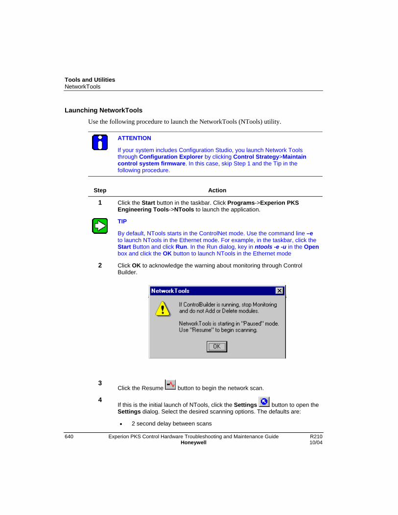
Tools and UtilitiesNetworkTools
640 Experion PKS Control Hardware Troubleshooting and Maintenance Guide R210Honeywell 10/04
Launching NetworkToolsUse the following procedure to launch the NetworkTools (NTools) utility.
ATTENTION
If your system includes Configuration Studio, you launch Network Toolsthrough Configuration Explorer by clicking Control Strategy>Maintaincontrol system firmware. In this case, skip Step 1 and the Tip in thefollowing procedure.
Step Action
1 Click the Start button in the taskbar. Click Programs->Experion PKSEngineering Tools->NTools to launch the application.
TIP
By default, NTools starts in the ControlNet mode. Use the command line –eto launch NTools in the Ethernet mode. For example, in the taskbar, click theStart Button and click Run. In the Run dialog, key in ntools -e -u in the Openbox and click the OK button to launch NTools in the Ethernet mode
2 Click OK to acknowledge the warning about monitoring through ControlBuilder.
3Click the Resume button to begin the network scan.
4If this is the initial launch of NTools, click the Settings button to open theSettings dialog. Select the desired scanning options. The defaults are:
• 2 second delay between scans
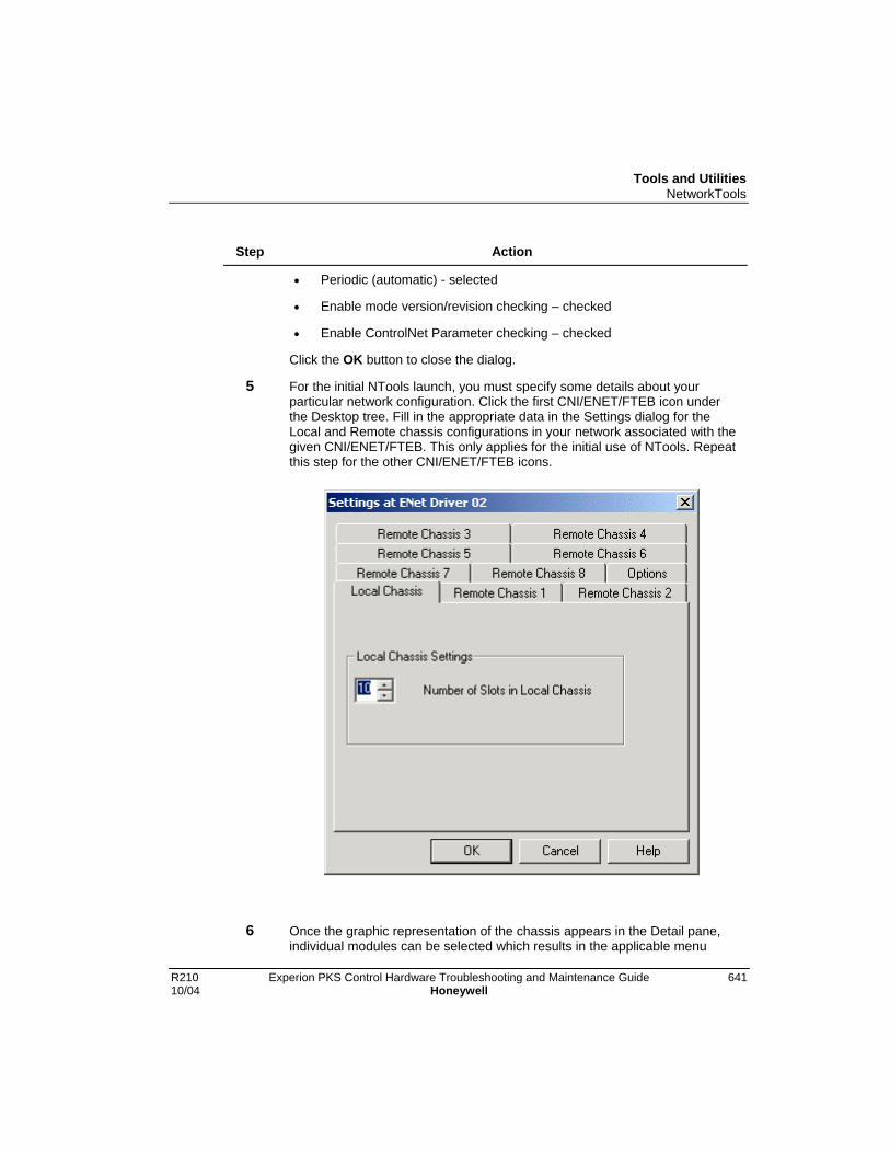
Tools and UtilitiesNetworkTools
R210 Experion PKS Control Hardware Troubleshooting and Maintenance Guide 64110/04 Honeywell
Step Action
• Periodic (automatic) - selected
• Enable mode version/revision checking – checked
• Enable ControlNet Parameter checking – checked
Click the OK button to close the dialog.
5 For the initial NTools launch, you must specify some details about yourparticular network configuration. Click the first CNI/ENET/FTEB icon underthe Desktop tree. Fill in the appropriate data in the Settings dialog for theLocal and Remote chassis configurations in your network associated with thegiven CNI/ENET/FTEB. This only applies for the initial use of NTools. Repeatthis step for the other CNI/ENET/FTEB icons.
6 Once the graphic representation of the chassis appears in the Detail pane,individual modules can be selected which results in the applicable menu
Tools and UtilitiesNetworkTools
642 Experion PKS Control Hardware Troubleshooting and Maintenance Guide R210Honeywell 10/04
Step Actionoptions becomming enabled.

Tools and UtilitiesNetworkTools
R210 Experion PKS Control Hardware Troubleshooting and Maintenance Guide 64310/04 Honeywell
Step Action

Tools and UtilitiesNetworkTools
644 Experion PKS Control Hardware Troubleshooting and Maintenance Guide R210Honeywell 10/04
Step Action
7 This completes the procedure.
Display Regions (panes)
By default, NetworkTools starts in the paused mode. Just click NetworkTools->Resumeto have NTools automatically start scanning all nodes on the Supervisory networksegment connected to your computer. Information is presented in three panes - the Treepane (on the upper left), the List pane (on the upper right) and, below them, the Detailpane. The List pane shows ControlNet/Ethernet/FTE related statistics maintained byNetworkTools.
Using the Detail Pane
Select one item (either the MAC ID of a CNI or the driver name for an Ethernet moduleor FTE Bridge module) from the Tree pane to populate the Detail pane with a C200Controller chassis and any associated remote chassis. You may be asked to provide the

Tools and UtilitiesNetworkTools
R210 Experion PKS Control Hardware Troubleshooting and Maintenance Guide 64510/04 Honeywell
details on the Controller (Local) chassis. If so, fill in the details requested by the Settingsdialog tab - use the applicable remote chassis tab, if you have any remote chassis. Notethat you must provide the MAC IDs for the CNIs in any Remote chassis and you mustprovide chassis slot positions for DownLink CNIs in your Local (Controller) Chassis.
You can display one Local chassis and up to eight Remote chassis at a time. Use theSettings selection on the NetworkTools menu to make adjustments at any time. Yoursettings are saved across sessions.
NetworkTools scans per your settings and reports results in a visual manner on eachmodule discovered. NetworkTools can be run in Periodic (automatic) mode or Ping(manual) mode. If Periodic mode is chosen, you can specify a number between 1 and 60that is the time, in seconds, that NetworkTools pauses between consecutive scans.Adjust this on the Settings dialog. You can pause and resume Periodic scanning.
The text in the cyan boxes is the string provided in the Device Identity Object - typically,the Model number with its TC- or TK- prefix suppressed for the sake of readability.
The green text in the black box is the human-readable version of the state informationacquired from the module during the scan. The Device Identity Object state is used for allmodules except the CPM for which the Extended Device Object state is used.
The V string in the box represents the Major (version) and Minor (revision) releaseidentifiers for the module.
The A and B text at the bottom of CNI modules indicates what ControlNet cable theywere using when last scanned. The Cable Redundancy Warning is indicated by a W (thismay appear if your system is only using a single ControlNet cable).

Tools and UtilitiesNetworkTools
646 Experion PKS Control Hardware Troubleshooting and Maintenance Guide R210Honeywell 10/04
Device Identity Dialog Box
To view details for a module in a chassis, click on the module’s face to highlight it. ClickDevice > Show Module Details to open the module’s Module Details dialog. Doubleclicking on the module will also launch the dialog.
CNI ControlNet Stats Dialog Box
With a CNI module selected, click Device > Show ControlNet Stats to openControlNet Stats dialog for the selected CNI. The CN Page1 tab is static data; the CNPage2 and CM0 tabs are dynamic data. When this dialog is showing, the normal scanningis suspended and the scanning for the statistics on the CN Page 2 or CM0 tab occursevery one-half second.
ENET TCP/IP Configuration
With an Ethernet module selected, click Device > TCP/IP Configuration to open theTCP/IP configuration dialog for the selected ENET. This dialog is only active whenNTools is started with the -U command line and an Ethernet module is selected. Whenthis dialog is showing, the normal scanning is suspended and the scanning for thestatistics on the second or third tab occurs every one-half second. This dialog containsthe following:
IP Address The IP Address for the Ethernet module
Subnet Mask The Subnet Mask for the IP Address of the Ethernet module
GatewayAddress
The Gateway Address for the Ethernet module
BOOTPEnable/Disableflag
On Checking this check box, the BOOTP flag in the module isenabled and on unchecking this, it is disabled.
If the BOOTP flag is enabled, the module expects a BOOTPserver on the Ethernet segment to provide it an IP Address, aSubnet Mask and a Gateway Address after the next power up.The module remains with all these three settings with all 0s until aBOOTP Server replies to the module and successfully gives it anIP Address, Subnet Mask and Gateway Address.
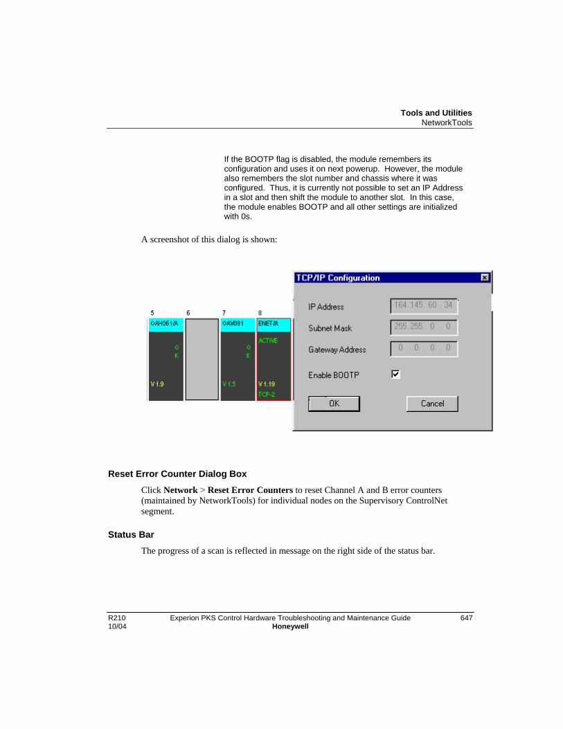
Tools and UtilitiesNetworkTools
R210 Experion PKS Control Hardware Troubleshooting and Maintenance Guide 64710/04 Honeywell
If the BOOTP flag is disabled, the module remembers itsconfiguration and uses it on next powerup. However, the modulealso remembers the slot number and chassis where it wasconfigured. Thus, it is currently not possible to set an IP Addressin a slot and then shift the module to another slot. In this case,the module enables BOOTP and all other settings are initializedwith 0s.
A screenshot of this dialog is shown:
Reset Error Counter Dialog Box
Click Network > Reset Error Counters to reset Channel A and B error counters(maintained by NetworkTools) for individual nodes on the Supervisory ControlNetsegment.
Status BarThe progress of a scan is reflected in message on the right side of the status bar.

Tools and UtilitiesNetworkTools
648 Experion PKS Control Hardware Troubleshooting and Maintenance Guide R210Honeywell 10/04
ControlNet Parameters
This section discusses the Keeper Values dialog box and its operation. This powerfulfeature should only be used by those with a thorough understanding of the operation ofControlNet. This function can only be used if you launched NetworkTools with the -pgcommand line.
The Change ControlNet Parameters command is on the Device menu because youmust select a keeper capable module for NetworkTools to effect the network changesoperation. The CNI modules have the Keeper Object that orchestrates the distribution ofnew network parameters to all segment nodes.
Depending on which keeper capable module is selected, all modules on thecorresponding ControlNet segment can be updated (i.e. the Supervisory network orsubsidiary I/O networks).
You can view the current ControlNet parameters by double-clicking on any CNI in thenetwork and reviewing the data on the CN Page1 tab of the ControlNet Stats dialog.
With any CNI selected, click Device > Change ControlNet Parameters to open theKeeper Values dialog. You can view the ControlNet parameters that are stored in theKeeper Object on the Present Keeper tab. These parameters may not represent theparameters in current use in the network, but would be impressed on the network, if thisCNI became the Keeper node and found that the network needed to have ControlNetparameters impressed upon it.
The parameters on the Future Keeper tab of the Keeper Values dialog for any specificCNI are just a calculation based on the values shown in the Changes tab of the KeeperValues dialog. These will be the parameters stored in this CNI's Keeper Object whenyou click the OK button. This is an operation that takes about 10 seconds – at the end youare told of the success and shown the Unique ID value that was impressed on the CNI –See the following section for more information.
Tools and UtilitiesNetworkTools
R210 Experion PKS Control Hardware Troubleshooting and Maintenance Guide 64910/04 Honeywell
ControlNet Unique ID
The Unique ID shown on the Present Keeper tab of the Keeper Values dialog isimportant for redundant chassis operation. It is strongly recommended that all CNIs at asite be programmed for the same ControlNet parameters. Each time a CNI isprogrammed for ControlNet parameters a “shorthand” code is calculated – the Unique ID– and it too is stored to the CNI. The Experion PKS default values are as follows:
SupervisoryNetwork
I/O Network
NUT 10000 10000
SMAX 1 1
UMAX 241 20
Repeaters 0 0
Cable Length 1000 1000
Channel Usage A+B A+B
Fiber Optics No No
Unique ID 0xa0b3b298 0x4687418c
1If your system requires more than 24 nodes, you can increase the UMAX to equal thenumber of nodes above 24 up to a maximum of 32.
If your site needs to be different than the values above (e.g. you use fiber optics) then adifferent Unique ID will result. Again, we strongly recommend that all CNIs at a site beprogrammed for the same ControlNet parameters.
If CNIs show “!CPT” in their four character display, it could be because of a Unique IDmis-match. To recover, update the ControlNet parameter settings for the secondary CNIand then power-cycle the secondary chassis, so that the CNIs reattempt their partnercompatibility checks.
Flash Upgrades to CNI firmware do not affect the previously-stored ControlNetparameter settings.

Tools and UtilitiesNetworkTools
650 Experion PKS Control Hardware Troubleshooting and Maintenance Guide R210Honeywell 10/04
Viewing SIM statisticsUse the following procedure to view SIM statistics in the open NTools window.
Step Action
1 Click the CNI icon under the Desktop tree for the chassis that contains a SIM.
2 In the Detail pane, click the graphic representation of the SIM in the chassisto select it.
3 Click Device->View SIM Details to call up the dialog box. Click the Pause
button to stop the network scan, if desired.
4 View the following statistics to determine if the rate of writes needs tuning.
• Updates/sec: Shows the number of arrays transferred from the FTA tothe SIM per second. Divide this number by the number of arrays to findthe per array update rate.
• Stores/sec: Shows the number of individual parameter writes persecond.
• Overruns/sec: Shows the number of parameter writes that were notaccepted per second. A non-zero value is signaled as an overrun.
5 Click OK to close the dialog box.
6 Click NetworkTools->Exit to close the application.
Getting RM Events
With a Redundancy Module (RM) selected, click Device > Show History to openRedundancy Module Events History dialog.
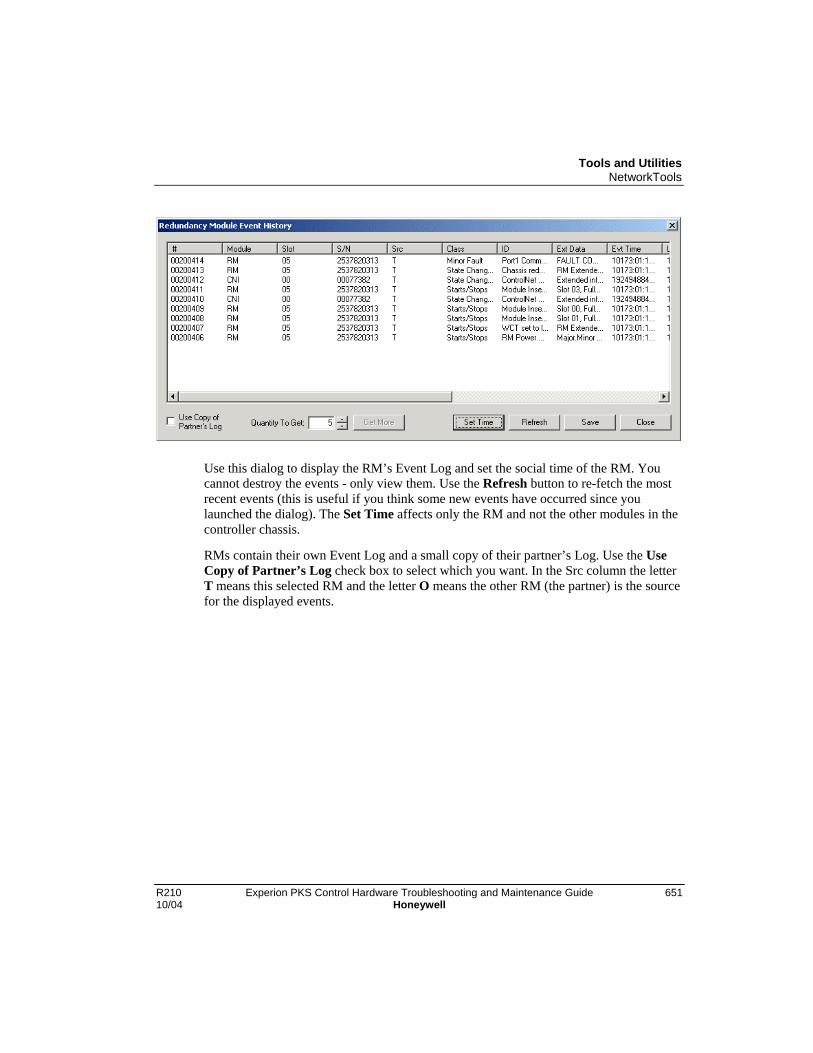
Tools and UtilitiesNetworkTools
R210 Experion PKS Control Hardware Troubleshooting and Maintenance Guide 65110/04 Honeywell
Use this dialog to display the RM’s Event Log and set the social time of the RM. Youcannot destroy the events - only view them. Use the Refresh button to re-fetch the mostrecent events (this is useful if you think some new events have occurred since youlaunched the dialog). The Set Time affects only the RM and not the other modules in thecontroller chassis.
RMs contain their own Event Log and a small copy of their partner’s Log. Use the UseCopy of Partner’s Log check box to select which you want. In the Src column the letterT means this selected RM and the letter O means the other RM (the partner) is the sourcefor the displayed events.
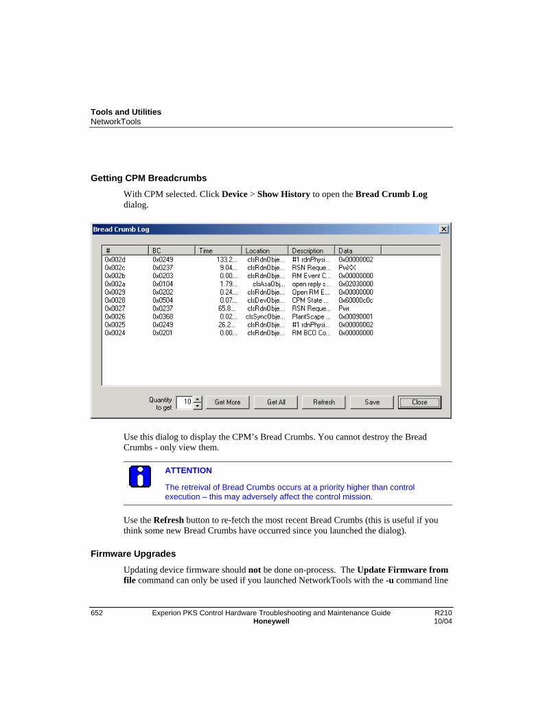
Tools and UtilitiesNetworkTools
652 Experion PKS Control Hardware Troubleshooting and Maintenance Guide R210Honeywell 10/04
Getting CPM Breadcrumbs
With CPM selected. Click Device > Show History to open the Bread Crumb Logdialog.
Use this dialog to display the CPM’s Bread Crumbs. You cannot destroy the BreadCrumbs - only view them.
ATTENTION
The retreival of Bread Crumbs occurs at a priority higher than controlexecution – this may adversely affect the control mission.
Use the Refresh button to re-fetch the most recent Bread Crumbs (this is useful if youthink some new Bread Crumbs have occurred since you launched the dialog).
Firmware Upgrades
Updating device firmware should not be done on-process. The Update Firmware fromfile command can only be used if you launched NetworkTools with the -u command line

Tools and UtilitiesNetworkTools
R210 Experion PKS Control Hardware Troubleshooting and Maintenance Guide 65310/04 Honeywell
or have selected the Enable updating device firmware check box on the Select optionsfor Network Tools dialog.
TIP
• You may be able to use the On-Process Migration function to update yourfirmware. See the On-Process Migration Planning Guide for moreinformation
• Read the Software Installation and Upgrades Guide for its discussion ofthis topic.
• Remove from the chassis all modules except the one you are about toupgrade. While this is not necessary, it removes distractions and moduleinteraction that could cause failure of the upgrade.
• Read the dialog boxes you are presented with very carefully. If you areever confronted with a dialog which is titled “Warning: Use ExtremeCare” be very certain before you click OK. If the text in that dialog says“The NVS file you have chosen does not contain a reference to themodule you selected” you may have selected an inappropriate image toFlash to the target module.

Tools and UtilitiesNetworkTools
654 Experion PKS Control Hardware Troubleshooting and Maintenance Guide R210Honeywell 10/04
CNI: Click the CNI in the chassis shown in the Detail Pane and click Device :>Update Firmware from file.
CPM: Click the CPM in the chassis shown in the Detail Pane and click Device :>Update Firmware from file. If you asked to change the state of the CPM,select OK but realize that this causes the CPM to re-boot. If you proceedtoo quickly to the actual Flashing operation (firmware upgrade), theoperation will fail (but in a graceful, recoverable way). Be sure you wait untilthe CPM has fully rebooted before proceeding with a firmware upgrade.
In some situations the Flashing operation starts but goes on and on until afailure is finally declared. This is a graceful, recoverable failure. But it ifhappens more than once, you are advised to shut down the CDA serviceand try again. (If you do this, remember to restart the CDA service).
ENET: Click the ENET in the chassis shown in the Detail Pane and click Device :>Update Firmware from file.
FTEB Click the FTEB in the chassis shown in the Detail Pane and click Device :>Update Firmware from file.
I/O: Click the applicable I/O Module in the chassis shown in the Detail Pane andclick Device :> Update Firmware from file. Be sure you select the correctfirmware for the selected I/O Module model.
PCIC: Click the PCIC icon in the Tree Pane and click Device :> Update Firmwarefrom file. We suggest that you shut down the CDA Service before startingthis operation.
RM: Click the applicable RM in the chassis shown in the Detail Pane and clickDevice :> Update Firmware from file. You cannot upgrade a RM that isshowing E054 or some other failure code on its 4-character display.
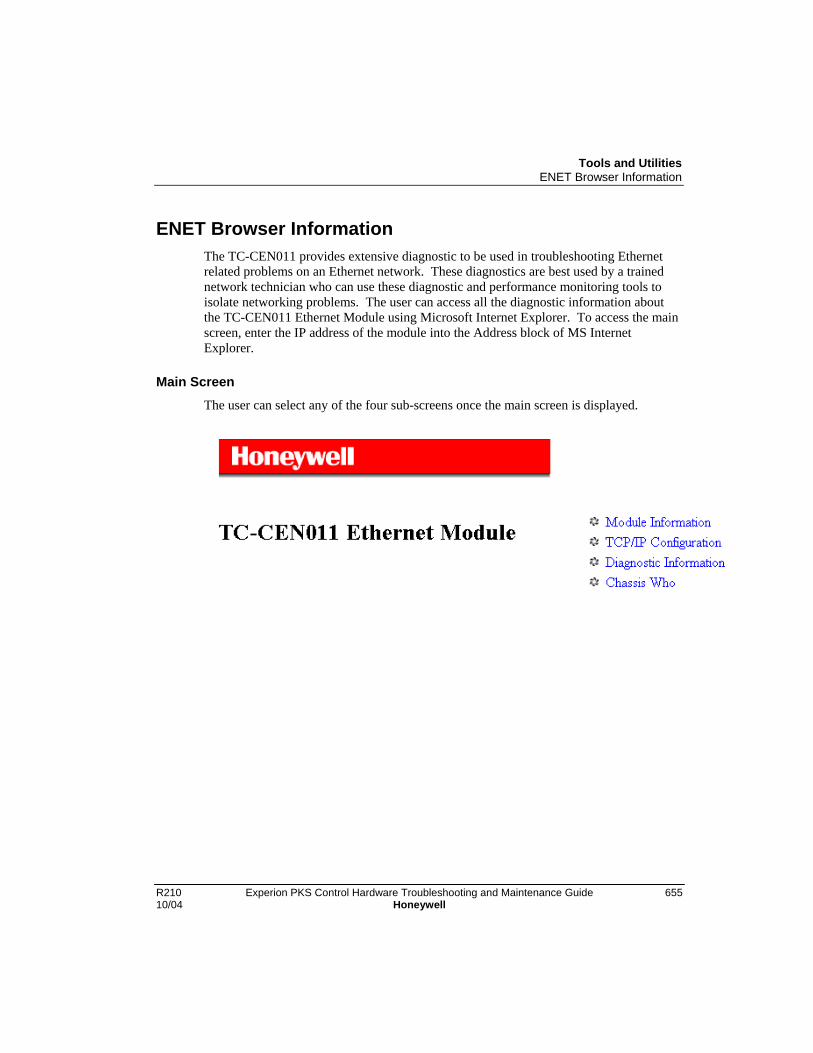
Tools and UtilitiesENET Browser Information
R210 Experion PKS Control Hardware Troubleshooting and Maintenance Guide 65510/04 Honeywell
ENET Browser InformationThe TC-CEN011 provides extensive diagnostic to be used in troubleshooting Ethernetrelated problems on an Ethernet network. These diagnostics are best used by a trainednetwork technician who can use these diagnostic and performance monitoring tools toisolate networking problems. The user can access all the diagnostic information aboutthe TC-CEN011 Ethernet Module using Microsoft Internet Explorer. To access the mainscreen, enter the IP address of the module into the Address block of MS InternetExplorer.
Main ScreenThe user can select any of the four sub-screens once the main screen is displayed.

Tools and UtilitiesENET Browser Information
656 Experion PKS Control Hardware Troubleshooting and Maintenance Guide R210Honeywell 10/04
Main Screen - Module Information
There is no user configurable or usable information on this screen. This screen is usefulfor advanced diagnostics and provides useful information for troubleshootingtechnicians.

Tools and UtilitiesENET Browser Information
R210 Experion PKS Control Hardware Troubleshooting and Maintenance Guide 65710/04 Honeywell
Main Screen - TCP/IP Configuration
TCP/IP Configuration - IP Address
The IP address identifies each node on the IP network (or system of connected networks).Each TCP/IP node on a network (including the Ethernet module) must have a unique IPaddress.
The IP address is 32 bits long and has a net ID part and a host ID part. Each network is aClass A, Class B, or Class C network. The class of a network determines how an IPaddress is formatted.
Each node on the same physical network must have an IP address of the same class andmust have the same net ID. Each node on the same network must have a different host IDthus giving it a unique IP address.
IP addresses are written as four decimal integers (0-255) separated by periods where eachinteger gives the value of one byte of the IP address. For example, the 32-bit IP address:
00000011 00000000 00000000 00000001 is written as 3.0.0.1.
Tools and UtilitiesENET Browser Information
658 Experion PKS Control Hardware Troubleshooting and Maintenance Guide R210Honeywell 10/04
You can distinguish the class of an IP address from the first integer in its dotted-decimalIP address as follows:
Range of firstinteger
Class Range of first integer Class
0 –127 A 192 – 223 C
128 –191 B 224 – 255 Other
Contact your network administrator or the Network Information Center for a unique IPaddress to assign to your module.
TCP/IP Configuration - Subnet Mask
Subnet addressing is an extension of the IP address scheme that allows a site to use asingle net ID for multiple physical networks. Routing outside of the site continues bydividing the IP address into a net ID and a host ID via the class. Inside a site, the subnetmask is used to redivide the IP address into a custom net ID portion and host ID portion.
Take Network 2 (a Class B network) in the previous example and add another physicalnetwork. Selecting the following subnet mask would add two additional net ID bitsallowing for four physical networks:
Example:
11111111 11111111 11000000 00000000 = 255.255.192.0
Two bits of the Class B host ID have been used to extend the net ID. Each uniquecombination of bits in the part of the host ID where subnet mask bits are 1 specifies adifferent physical network.

Tools and UtilitiesENET Browser Information
R210 Experion PKS Control Hardware Troubleshooting and Maintenance Guide 65910/04 Honeywell
TCP/IP Configuration - Gateway Mask
A gateway connects individual physical networks into a system of networks. When anode needs to communicate with a node on another network, a gateway transfers the databetween the two networks. The following figure shows gateway G connecting Network 1with Network 2.
When host B with IP address 128.2.0.1 communicates with host C, it knows from C’s IPaddress that C is on the same network. In an Ethernet environment, B can then resolveC’s IP address to a MAC address (via ARP) and communicate with C directly.
When host B communicates with host A, it knows from A’s IP address that A is onanother network (the net IDs are different). In order to send data to A, B must have the IPaddress of the gateway connecting the two networks. In this example, the gateway’s IPaddress on Network 2 is 128.2.0.3.
The gateway has two IP addresses (128.1.0.2 and 128.2.0.3). The first must be used byhosts on Network 1 and the second must be used by hosts on Network 2. To be usable, ahost’s gateway must be addressed using a net ID matching its own.
TCP/IP Configuration - Name Server and Secondary Name Server
In Internet terminology, computers referred to as name servers provide services thatmaintain name-to-IP address mappings. These DNS name servers provide thisinformation to client computers and programs that need to connect to other computers ona network. Name servers provide a look-up service. Please refer to the networkadministrator for more information regarding name servers.
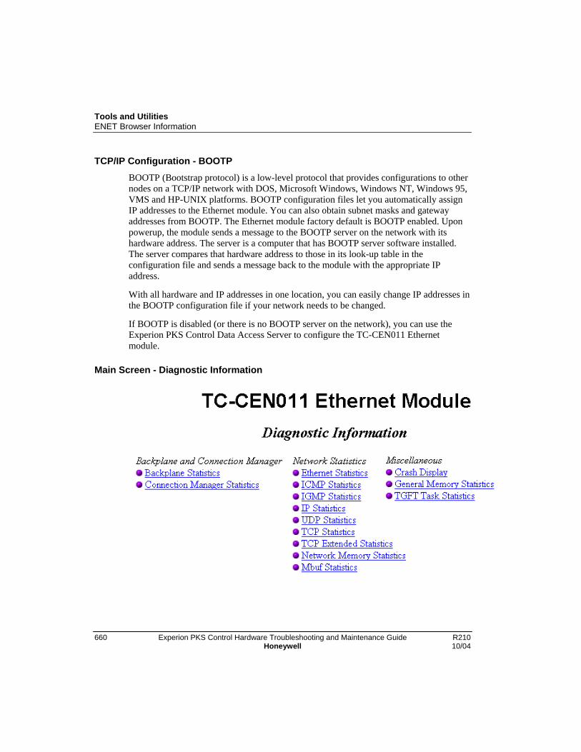
Tools and UtilitiesENET Browser Information
660 Experion PKS Control Hardware Troubleshooting and Maintenance Guide R210Honeywell 10/04
TCP/IP Configuration - BOOTP
BOOTP (Bootstrap protocol) is a low-level protocol that provides configurations to othernodes on a TCP/IP network with DOS, Microsoft Windows, Windows NT, Windows 95,VMS and HP-UNIX platforms. BOOTP configuration files let you automatically assignIP addresses to the Ethernet module. You can also obtain subnet masks and gatewayaddresses from BOOTP. The Ethernet module factory default is BOOTP enabled. Uponpowerup, the module sends a message to the BOOTP server on the network with itshardware address. The server is a computer that has BOOTP server software installed.The server compares that hardware address to those in its look-up table in theconfiguration file and sends a message back to the module with the appropriate IPaddress.
With all hardware and IP addresses in one location, you can easily change IP addresses inthe BOOTP configuration file if your network needs to be changed.
If BOOTP is disabled (or there is no BOOTP server on the network), you can use theExperion PKS Control Data Access Server to configure the TC-CEN011 Ethernetmodule.
Main Screen - Diagnostic Information

Tools and UtilitiesENET Browser Information
R210 Experion PKS Control Hardware Troubleshooting and Maintenance Guide 66110/04 Honeywell
Diagnostic Information - Network Statistics
The Network Statistics define statistics that are industry standards and are defined in the“Management Information Base for Network Management of TCP/IP-based internets”Request For Comments RFC 1156. No additional detail will be provided here. Thesestatistics are used by Network Administrators to monitor the health of a TCP/IP network.They are provided here for reference only.
Network Statistics - Ethernet Statistics

Tools and UtilitiesENET Browser Information
662 Experion PKS Control Hardware Troubleshooting and Maintenance Guide R210Honeywell 10/04
Network Statistics - ICMP Statistics
Network Statistics - IGMP Statistics

Tools and UtilitiesENET Browser Information
R210 Experion PKS Control Hardware Troubleshooting and Maintenance Guide 66310/04 Honeywell
Network Statistics - IP Statistics
Network Statistics - UDP Statistics

Tools and UtilitiesENET Browser Information
664 Experion PKS Control Hardware Troubleshooting and Maintenance Guide R210Honeywell 10/04
Network Statistics - TCP Statistics
Network Statistics - TCP Extended Statistics

Tools and UtilitiesENET Browser Information
R210 Experion PKS Control Hardware Troubleshooting and Maintenance Guide 66510/04 Honeywell
Network Statistics - Network Memory Statistics
Network Statistics - Mbuf Statistics

Tools and UtilitiesENET Browser Information
666 Experion PKS Control Hardware Troubleshooting and Maintenance Guide R210Honeywell 10/04
Diagnostic Information - Miscellaneous
The following three sections have no user configurable or usable information on thisscreen. This screen is useful for advanced diagnostics and provides useful informationfor troubleshooting technicians.
Miscellaneous - Crash Display
Miscellaneous - General Memory Statistics
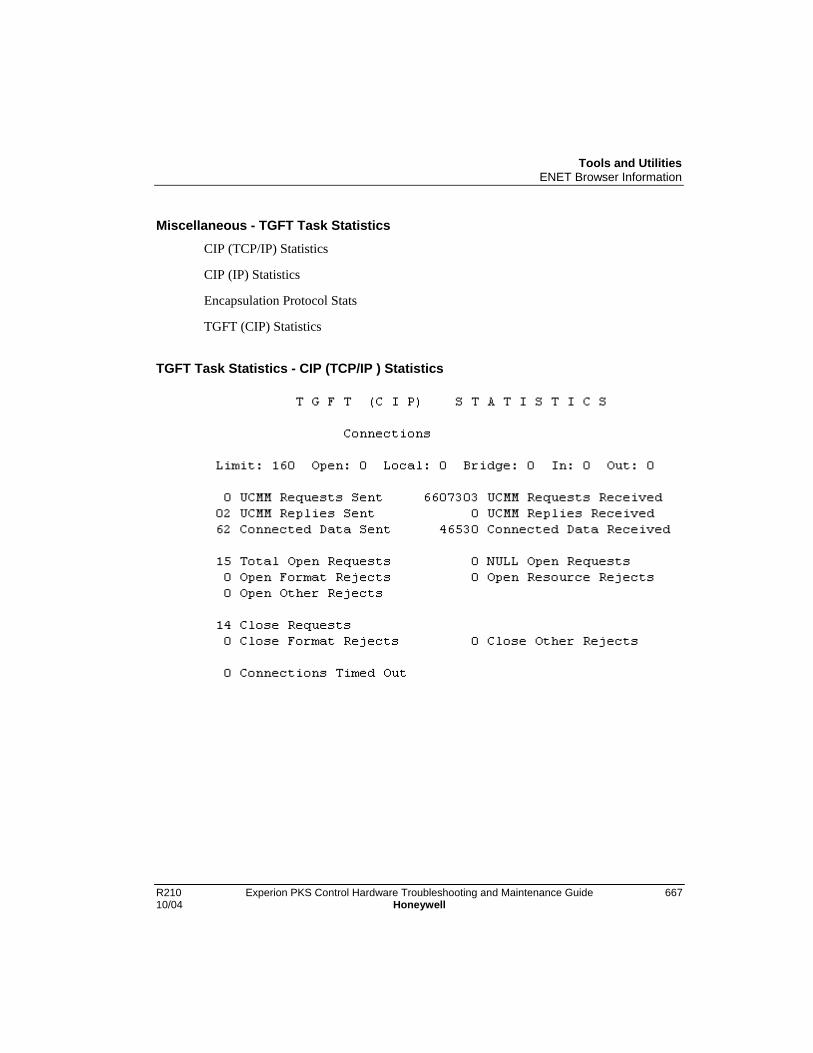
Tools and UtilitiesENET Browser Information
R210 Experion PKS Control Hardware Troubleshooting and Maintenance Guide 66710/04 Honeywell
Miscellaneous - TGFT Task StatisticsCIP (TCP/IP) Statistics
CIP (IP) Statistics
Encapsulation Protocol Stats
TGFT (CIP) Statistics
TGFT Task Statistics - CIP (TCP/IP ) Statistics

Tools and UtilitiesENET Browser Information
668 Experion PKS Control Hardware Troubleshooting and Maintenance Guide R210Honeywell 10/04
TGFT Task Statistics - CIP (IP) Statistics
TGFT Task Statistics - Encapsulation Protocol Stats
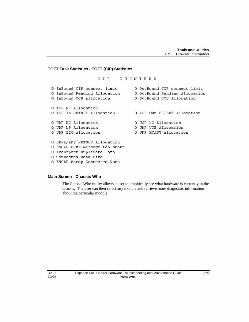
Tools and UtilitiesENET Browser Information
R210 Experion PKS Control Hardware Troubleshooting and Maintenance Guide 66910/04 Honeywell
TGFT Task Statistics - TGFT (CIP) Statistics
Main Screen - Chassis Who
The Chassis Who utility allows a user to graphically see what hardware is currently in thechassis. The user can then select any module and retrieve more diagnostic informationabout the particular module.

Tools and UtilitiesENET Browser Information
670 Experion PKS Control Hardware Troubleshooting and Maintenance Guide R210Honeywell 10/04

R210 Experion PKS Control Hardware Troubleshooting and Maintenance Guide 67110/04 Honeywell
Effective Trouble Reporting
What Makes A PAR EffectiveA PAR (Product Anomoly Report) is the formal means by which problems aredocumented, from identification to eventual resolution, fix verification, and closure.
The life cycle of a PAR is very much dependent on a thorough description of theproblem. When filing a PAR, the following guidelines will help enhance theeffectiveness of the report:
Clue Value
Component Version& Revision
Problems are many times unique to a release or set ofreleases. Code inspections and problem reproducability aredependent on this information.
Always provide the Experion PKS release number, e.g.,EXP100.0-24.1.
Where a problem has been localized to a module or modules,go to NetworkTools and get the version/revision numbers forthose modules. To reinforce the Experion PKS releasenumber, it is also helpful to record RSLinx, KTC and CNIrelease numbers.
TAC will contact the user if specific version/revisioninformation is needed.
Topology A general description of the system topology is usuallyimportant.
e.g., Redundant server, dual media ControlNet, 1 RCP with 2downlinks, 1 RCP with 1 downlink, and 1 non-redundantcontroller with 2 downlinks, single I/O rack with all downlinks.
If the problem is thought to be topology oriented, then a moredetailed description/drawing is appropriate, including MAC IDassignments.
Symptoms What about system operation is abnormal?
What CNI, CPM, RM, CB, and/or SCAN error/fault indicators(LED states or error codes) are present?
What alarms surround the abnormal condition?
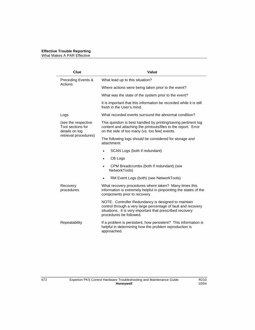
Effective Trouble ReportingWhat Makes A PAR Effective
672 Experion PKS Control Hardware Troubleshooting and Maintenance Guide R210Honeywell 10/04
Clue Value
Preceding Events &Actions
What lead up to this situation?
Where actions were being taken prior to the event?
What was the state of the system prior to the event?
It is important that this information be recorded while it is stillfresh in the User’s mind.
Logs
(see the respectiveTool sections fordetails on logretrieval procedures)
What recorded events surround the abnormal condition?
This question is best handled by printing/saving pertinent logcontent and attaching the printouts/files to the report. Erroron the side of too many (vs. too few) events.
The following logs should be considered for storage andattachment:
• SCAN Logs (both if redundant)
• CB Logs
• CPM Breadcrumbs (both if redundant) (seeNetworkTools)
• RM Event Logs (both) (see NetworkTools)
Recoveryprocedures
What recovery procedures where taken? Many times thisinformation is extremely helpful in pinpointing the states of thecomponents prior to recovery.
NOTE: Controller Redundancy is designed to maintaincontrol through a very large percentage of fault and recoverysituations. It is very important that prescribed recoveryprocedures be followed.
Repeatability If a problem is persistent, how persistent? This information ishelpful in determining how the problem reproduction isapproached.

PM I/O Component DescriptionIntroduction
R210 Experion PKS Control Hardware Troubleshooting and Maintenance Guide 67310/04 Honeywell
PM I/O Component Description
IntroductionThis section provides a quick reference to various topics related to Process Manager I/Oassemblies and components that may be helpful in troubleshooting PM I/O subsystemfaults.
Component part numbers
The Honeywell part numbers for all components described in this section are listed inSpare Parts
PM I/O Component DescriptionPower System Controls
674 Experion PKS Control Hardware Troubleshooting and Maintenance Guide R210Honeywell 10/04
Power System ControlsControl of ac power to the Power Supply Modules is provided by two methods when thecontrol cabinet contains the normal Standard Power System components.
AC power control
All ac power to the control cabinet, which includes any cabinet fan assemblies, iscontrolled by a dedicated circuit breaker that is supplied by the user for each powersupply module in the power system. Additional ac power supply module control isprovided by a power switch that is mounted at the front of each module.
DC power control
Since the standard power system can contain redundant power supply modules, placing amodule’s power switch in the off position does not necessarily remove power from thecontroller chassis, IOP card files and Field Termination Assemblies (FTAs) in the cabinetbecause the second module will continue to supply power unless its Power switch is inthe off position.
If the standard power system contains a battery backup module, 24 Vdc power willcontinue to be supplied to the controller chassis, card files and FTAs unless theBATTERY switch is placed in the off position, or the battery backup module isdischarged. All three switches must be in the off position to completely remove powerfrom the equipment.
AC Only Power System
In a cabinet that contains an AC Only Power System, no battery backup module exists toprovide 24 Vdc power to the equipment, so control of dc power to the controller chassis,card files and FTAs is provided exclusively by user supplied ac circuit breakers. Whenredundant power supply modules exist, each module has its own circuit breaker that isprovided by the user. There is no on-off switch at the front of the power supply module.
IOP Card Power Interrupt Switches
The PM I/O Link cards, and each IOP card have a 24 Vdc power interrupt switch that isactivated by unlocking and lifting the upper card extractor/insertion lever. Activating anIOP card power interrupt switch removes power only from that IOP card. Power isremoved only while the switch is activated.

PM I/O Component DescriptionPower System Controls
R210 Experion PKS Control Hardware Troubleshooting and Maintenance Guide 67510/04 Honeywell
WARNING
The loss of power to an analog or digital output IOP causes the loss of theIOP’s outputs to the field connections. Analog output IOP outputs drop to anonpowered state (-6.9%), and the digital output IOP outputs are set to theiroff state.
The nonpowered state of the output IOPs should result in a safe condition forpersonnel, the plant, and the process under control.

PM I/O Component DescriptionPM I/O Subsystem Overview
676 Experion PKS Control Hardware Troubleshooting and Maintenance Guide R210Honeywell 10/04
PM I/O Subsystem Overview
Major assemblies
The Process Manager I/O (PM I/O) subsystem is comprised of the major assemblies thatare described in the following subsections. The following figure is a view of a singlecabinet containing nonredundant IOP card files and identifies some of PM I/Oassemblies. The PM I/O major assemblies are:
• Left 7-Slot IOPCard File (Slots 1 through 7)
• Right 7-Slot IOP Card File (Slots 9 through 15)
• 15-Slot IOPCard File
• Input/Output Processor Cards (IOPs)
• Field Termination Assemblies (FTAs)
• Power Systems

PM I/O Component DescriptionPM I/O Subsystem Overview
R210 Experion PKS Control Hardware Troubleshooting and Maintenance Guide 67710/04 Honeywell
Single Control Cabinet with PM I/O

PM I/O Component DescriptionPM I/O Subsystem Overview
678 Experion PKS Control Hardware Troubleshooting and Maintenance Guide R210Honeywell 10/04
Card file types
Three types of card files can accommodate Input/Output Processor (IOP) cards. The Left7-Slot (Slots 1 through 7), Right 7-Slot Card File (Slots 9 through 15) and 15-Slot cardfiles.
IOP Card File Models
Card File Description CE Compliant Non-CE Compliant
Left 7-Slot MU-HPFI03 MU-HPFH01
Right 7-Slot MU-HPFI13 MU-HPFH11
15-Slot MU-HPFI23 MU-HPFX02
Total number of card files
The number of card files that can exist in a single PM I/O subsystem is dependent uponthe mix of 7-Slot and 15-Slot card files. Eight I/O Link addresses are available for use inthe PM I/O subsystem. Each card file must be assigned a unique I/O Link Interfaceaddress. Two 7-Slot card files can share the same I/O Link address if one is a Left cardfile (slots 1-7) and the other a Right card file (slots 9-15). The 15-Slot card file cannotshare its I/O Link address with another card file. It is conceivable that sixteen 7-Slot cardfiles can exist in a PM I/O subsystem (eight Left 7-Slot and eight Right 7-Slot card files).
Remote card file installation
IOP card files can be installed at remote locations through the use of I/O Link Extendercards that are installed in the card files. I/O Link Extender cards provide thecommunications link between the local control cabinet or cabinet complex and theremote location card files.
Total number of IOPs
Depending upon the configuration of IOP types, up to 40 primary IOPs, 40 secondary(redundant) IOPs, and 3 I/O Link Extenders (a maximum of 8 I/O Link Extender cards)can exist in a single PM I/O subsystem.

PM I/O Component DescriptionPM I/O Subsystem Overview
R210 Experion PKS Control Hardware Troubleshooting and Maintenance Guide 67910/04 Honeywell
15-Slot IOP card fileThe following figure illustrates a 15-slot IOP card file.
15-Slot IOP Card File

PM I/O Component DescriptionPM I/O Subsystem Overview
680 Experion PKS Control Hardware Troubleshooting and Maintenance Guide R210Honeywell 10/04
Types of Input/Output Processors (IOPs)
There are various types of IOP card assemblies. Some IOP card types interface withmore than one type of Field Termination Assembly (FTA). The functional types of IOPsare:
• High Level Analog Input (HLAI)
• Low Level Analog Input (LLAI)
• Low Level Analog Multiplexer (LLMux)
• Remote Hardened Low Level Analog Multiplexer (RHMUX)
• Digital Input (DI)
• Analog Output (AO)
• Digital Output (DO)
• Smart Transmitter Interface (STI)
• Smart Transmitter Interface Multivariable (STIM)
• Digital Input Sequence of Events (DISOE)
Some of the functional types of IOPs support only certain associated Field TerminationAssemblies (FTAs) models because the number of channels (Points) differ. Examplesare the Analog Output (8 and 16 channels) and Digital Output (16 and 32 channels) IOPs.
Redundant IOPs
IOPs can be connected in a redundant configuration with both IOPs connected byseparate cables to the same FTA. Some models of the following types of IOPs supportredundancy.
• Smart Transmitter Interface (STI)
• High Level Analog Input (HLAI)
• Digital Input (DI)
• Digital Output (DO)
The following figure illustrates an HLAI FTA that interfaces with a pair of HLAI IOPsthat are installed in separate 7-Slot card files.

PM I/O Component DescriptionPM I/O Subsystem Overview
R210 Experion PKS Control Hardware Troubleshooting and Maintenance Guide 68110/04 Honeywell
HLAI FTA with Redundant HLAI IOPs
Redundant AO IOPs
When an Analog Output FTA interfaces with two IOPs through separate cables, and anautomatic selector switch on the FTA selects which IOP’s output drives the field wiringterminal connectors on the FTA.

PM I/O Component DescriptionPM I/O Subsystem Overview
682 Experion PKS Control Hardware Troubleshooting and Maintenance Guide R210Honeywell 10/04
Low Level Multiplexer IOP (LLMux)
A Low Level Analog Input Multiplexer (LLMux) IOP processes up to 32 inputs fromtwo 16 input FTAs.
The following figure illustrates LLMux FTA interconnections for non-CE CompliantFTA models. CE Compliant FTA models are similar. See Process Manager I/OInstallation and Wiringin the Control Hardware Installation Guide for detailedinformation.
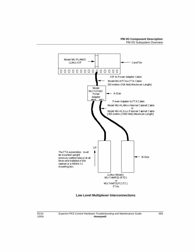
PM I/O Component DescriptionPM I/O Subsystem Overview
R210 Experion PKS Control Hardware Troubleshooting and Maintenance Guide 68310/04 Honeywell
Low Level Multiplexer Interconnections
PM I/O Component DescriptionField Termination Assemblies for IOPs
684 Experion PKS Control Hardware Troubleshooting and Maintenance Guide R210Honeywell 10/04
Field Termination Assemblies for IOPs
Two types of FTAs
There are two types of FTAs, Thermocouple (TC) and Resistive Temperature Device(RTD), that are connected to the IOP through a Power Adapter assembly as shown in inthe previous figure. One TC and one RTD FTA, or two of the same type FTAs can beconnected to one IOP through the Power Adapter. See Planning for Low LevelMultiplexer IOP in the Planning Guide for detailed information.
Power Adapter
The Power Adapter provides power to the FTA(s) from the IOP and can be installed onan FTA mounting channel.
The Power Adapter assembly has two LEDs, one for each cable that indicates a groundedor shorted cable. Each FTA has an LED that indicates the FTA is receiving power
IOP to Power Adapter connection
The IOP to Power Adapter connection is made using the standard model MU-KFTAxx(the suffix “xx” in the model number represents the length of the cable in meters) IOP toFTA cable. The maximum allowable length is 50 meters (164 feet).
For CE Compliance applications, the model MU-KFTSxx IOP to FTA cable must beused.
Power Adapter to FTA connection
The Power Adapter connects to either FTA type with a model MU-KLAMxx (internalcabinet use) or model MU-KLXxxx (external cabinet use) cable (one per FTA) as shownin the previous figure. The cable is limited to a maximum length of 305 meters (1000feet).
The model MU-KLAMxx cable has two individually shielded, twisted pair wires. Theshield must be connected to ground at the Power Adapter end of the cable only.
The model MU-KLXxxx external cabinet cable has four wires with a single braidedshield. The braided shield must be connected to ground at both the Power Adapter andFTA ends of the cable.
For CE Compliance applications, Belden model 83654 braided shield cable must be used.

PM I/O Component DescriptionField Termination Assemblies for IOPs
R210 Experion PKS Control Hardware Troubleshooting and Maintenance Guide 68510/04 Honeywell
Remote Hardened Low Level Multiplexer IOP (RHMUX)
The Remote Hardened Low Level Analog Input Multiplexer (RHMUX) IOP can processup to 32 inputs from two 16-input FTAs. The following figure illustrates the RHMUXIOP, Power Adapter, and Thermocouple FTA interconnections for a CE Compliantapplication.

PM I/O Component DescriptionField Termination Assemblies for IOPs
686 Experion PKS Control Hardware Troubleshooting and Maintenance Guide R210Honeywell 10/04
Remote Hardened Low Level Multiplexer Interconnections

PM I/O Component DescriptionField Termination Assemblies for IOPs
R210 Experion PKS Control Hardware Troubleshooting and Maintenance Guide 68710/04 Honeywell
RHMUX Thermocouple FTA
One or two Thermocouple (TC) type RHMUX FTAs can be connected to a RHMUXIOP through either an Intrinsically Safe (IS) or Non-Incendive (NI) Power Adapterassembly.
FTA and Power Adapter installation
The Power Adapter provides power to the FTA(s) from the IOP. Both types of PowerAdapters can be installed on an FTA mounting channel. The FTA’s dimensions (size)are non-standard and prevent installing the FTA on a standard FTA mounting channel.
The Power Adapter assembly has two LEDs, one for each cable, that indicate a groundedor shorted cable. Each FTA has an LED that indicates the FTA is receiving power.
IOP to Power Adapter connection
The IOP to Power Adapter connection is made using the standard model MU-KFTAxx(the suffix “xx” in the model number represents the length of the cable in meters) IOP toFTA cable. The maximum allowable length is 50 meters (164 feet).
For CE Compliance applications, the model MU-KFTSxx IOP to FTA cable must beused.
Power Adapter to FTA connection
The Power Adapter connects to the FTA through a model MU-KLXxxx (internal cabinetuse) or model MU-KLO305 (external cabinet use) cable (one per FTA). The model MU-KLXxxx cable is limited to a maximum length of 305 meters (1000 feet), while themodel MU-KLO305 cable is 305 meters in length, the cable type (Belden YC41926) canbe used in lengths of up to 2000 meters (6560 feet).
Both types of cables have four conductors in a single-twist with a single braided shield.The shield must be connected to ground at both the Power Adapter and FTA ends of thecable.
PM I/O Component DescriptionI/O Link Extender (Fiber Optic Link)
688 Experion PKS Control Hardware Troubleshooting and Maintenance Guide R210Honeywell 10/04
I/O Link Extender (Fiber Optic Link)The I/O Link Extender provides the ability to locate 7-Slot and 15-Slot IOP card files andassociated FTAs up to 8 kilometers (5 miles) from the IOLIM. Two types of I/O Linkextenders and their associated fiber optical coupler modules are available, the “Standard”I/O Link extender which provides up to a 1.3 kilometers (4000 feet) link, and the “LongDistance” I/O Link extender which provides up to an 8 kilometers (5 miles) link. Theconnection is made using a pair of fiber optic transmission cables, driven and terminatedby a fiber optical coupler module that mates with the connector located directly belowthe card file slot in which the I/O Link extender card is installed.
Features and guidelines
• Each I/O Link extender consists of two I/O Link extender cards, one for Link Aand one for Link B, which occupy two slots in the IOP card file.
• Each Standard I/O Link extender card has an associated fiber optical couplermodule that can drive up to three pair of fiber optic cables. Each cable pair isterminated by a fiber optical coupler module that terminates one fiber optic pair.
• Each long distance I/O Link extender card has an associated fiber coupler thatdrives a single pair of fiber optic cables. Each cable pair is terminated by a fiberoptical coupler module that terminates one fiber optic pair.
• Every remote card file, or complex of IOP card files, requires two I/O Linkextender cards and two fiber optical coupler modules, one for Link A and onefor Link B. The Standard I/O Link extender card will drive and terminate LinkA or Link B, depending upon the card file number and card file slot number. Ifthe card file number and card file’s slot number are both odd or both even, thecard will drive Link A. If the card file number and card file’s slot number arenot both odd or both even, the card will drive Link B. The Link A or Link Bselection for the long distance I/O Link extender is determined by a jumper onthe card.
• Two Standard I/O Link Extender cards, connecting up to six remote card files,can be installed in an IOP card file, but the maximum number of other primaryIOPs is still 40 (plus 40 redundant IOPs).
• The maximum fiber optic cable length is dependent upon the number of splicesand quality of the cable (dB loss per meter of cable). This maximum can bebetween 0.98 and 1.3 kilometers for the Standard I/O Link Extender and 8kilometers for the Long Distance I/O Link Extender. See the Signal LossBudget calcaulationin the Planning Guide.

PM I/O Component DescriptionI/O Link Extender (Fiber Optic Link)
R210 Experion PKS Control Hardware Troubleshooting and Maintenance Guide 68910/04 Honeywell
Front panel indicators
Two visual front panel indicators are provided on the I/O Link Extender card that areconsistent with the display of IOP card indicators. The upper indicator is illuminated ifthe fused +24 Vdc is present on the card (the input voltage is acceptable). The lowerindicator denotes status.
Status indicator operation
In normal operation, the lower indicator is illuminated when messages are beingtransmitted from the fiber optic cable. The indicator should be fully lit or slightlyflickering, depending on system loading. Abnormal operation will result in the anti-jabber circuit locking up the transmitter circuit when the transmission period has been toolong. The indicator will then be off. If the fiber optical coupler module is improperlyinstalled, the indicator will blink at a 50% duty cycle. The anti-jabber circuit can be resetby cycling the upper extractor/insertion lever power switch on the I/O Link extendercard. For the long distance I/O Link extender, cycling power resets both ends of the link.The standard I/O Link extender must be manually reset at both ends of the link. The longdistance I/O Link extender can be reset by cycling power at one end of the link.
For more detailed information on I/O Link Extender installation and system components,refer to Installing Remote I/O in the Control Hardware Installation Guide.

PM I/O Component DescriptionField Termination Assemblies (FTAs)
690 Experion PKS Control Hardware Troubleshooting and Maintenance Guide R210Honeywell 10/04
Field Termination Assemblies (FTAs)Terminal connectors on FTAs provide the connection points for the process controlwiring to sense, condition, or operate the connected device. Depending upon the type ofFTA, fuses, relays, and resistors protect the FTA circuitry. The FTA communicates withan associated IOP, which in turn communicates with the IOLIM.
FTAs types
Standard types of FTAs, as described in the following table, interface the field wiring andprovide communication with an associated IOP. They are categorized as “standard”because types of galvanically isolated FTAs are also available as described below.
The model and part numbers for available individual FTAs of each type can be found inthe Spare Parts.
Detailed descriptions
Refer to the Process Manager I/O Installation and Wiringin the Control HardwareInstallation Guide for a more detailed description and installation information of eachFTA.
Standard Field Termination Assembly Types
FTA Type Description
High Level AnalogInput/Smart TransmitterInterface (HLAI/STI)
Accepts high level analog inputs. The inputs are configurable assingle-ended or differential in relation to logic common. This FTA isalso used to interface a Smart Transmitter device.
High Level Analog Input(HLAI)
Accepts high level analog inputs. The inputs are configurable assingle-ended or differential in relation to logic common.
Smart TransmitterInterface (STI)
Interfaces with Smart Transmitter devices. The interface isreferenced to logic ground. The Smart Transmitter provides fieldisolation.
Low Level Analog Input(LLAI)
Can be configured to accept low-level or high-level analog inputs.Low-level analog inputs include Thermocouples (TC), ResistanceTemperature Detectors (RTDs), or millivolt sources. High-levelinputs such as voltage sources (0-5 V) and 4-20 milliamp currentloop devices are acceptable.The inputs are isolated from each otherand the IOLIM, but share a common bus for field wire shields.
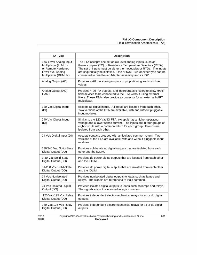
PM I/O Component DescriptionField Termination Assemblies (FTAs)
R210 Experion PKS Control Hardware Troubleshooting and Maintenance Guide 69110/04 Honeywell
FTA Type Description
Low Level Analog InputMultiplexer (LLMux)or Remote HardenedLow Level AnalogMultiplexer (RHMUX)
The FTA accepts one set of low-level analog inputs, such asthermocouples (TC) or Resistance Temperature Detectors (RTDs).The set of inputs must be either thermocouples or RTDs. The inputsare sequentially multiplexed. One or two FTAs of either type can beconnected to one Power Adapter assembly and its IOP.
Analog Output (AO) Provides 4-20 mA analog outputs to proportioning loads such asvalves.
Analog Output (AO)HART
Provides 4-20 mA outputs, and incorporates circuitry to allow HARTfield devices to be connected to the FTA without using externalfilters. These FTAs also provide a connector for an external HARTmultiplexer.
120 Vac Digital Input(DI)
Accepts ac digital inputs. All inputs are isolated from each other.Two versions of the FTA are available, with and without pluggableinput modules.
240 Vac Digital Input(DI)
Similar to the 120 Vac DI FTA, except it has a higher operatingvoltage and a lower sense current. The inputs are in four groups ofeight circuits with a common return for each group. Groups areisolated from each other.
24 Vdc Digital Input (DI) Accepts contacts grouped with an isolated common return. Twoversions of the FTA are available, with and without pluggable inputmodules.
120/240 Vac Solid-StateDigital Output (DO)
Provides solid-state ac digital outputs that are isolated from eachother and the IOLIM.
3-30 Vdc Solid-StateDigital Output (DO)
Provides dc power digital outputs that are isolated from each otherand the IOLIM.
31-200 Vdc Solid-StateDigital Output (DO)
Provides dc power digital outputs that are isolated from each otherand the IOLIM.
24 Vdc NonisolatedDigital Output (DO)
Provides nonisolated digital outputs to loads such as lamps andrelays. The signals are referenced to logic common.
24 Vdc Isolated DigitalOutput (DO)
Provides isolated digital outputs to loads such as lamps and relays.The signals are not referenced to logic common.
120 Vac/125 Vdc RelayDigital Output (DO)
Provides independent electromechanical relays for ac or dc digitaloutputs.
240 Vac/125 Vdc RelayDigital Output (DO)
Provides independent electromechanical relays for ac or dc digitaloutputs.

PM I/O Component DescriptionField Termination Assemblies (FTAs)
692 Experion PKS Control Hardware Troubleshooting and Maintenance Guide R210Honeywell 10/04
Galvanically isolated FTAsGalvanically isolated FTA types are listed in following table.
Galvanically Isolated Field Termination Assembly Types
FTA Type Description
High Level Analog Input(HLAI/STI)
The HLAI/STI FTA accepts high level analog inputs. Some FTAmodels also interface with Smart Transmitter devices. All inputs areisolated from ground and each other.
24 Vdc Digital Input (DI) The 24 Vdc DI FTA accepts contact inputs. All inputs are isolatedfrom each other.
Analog Output (AO) The AO FTA provides isolated 4-20 mA outputs to proportioningloads such as valves.
Analog Output (AO)HART
Provides 4-20 mA outputs, and incorporates circuitry to allow HARTfield devices to be connected to the FTA without using external filters.These FTAs also provide a connector for an external HARTmultiplexer.
24 Vdc Digital Output(DO)
The 24 Vdc DO FTA provides isolated digital outputs to loads such assolenoid valves or lamps.
Three physical sizes
The standard FTAs have three physical sizes as illustrated in the following figure. TheGalvanically isolated FTAs are one size only, B-size.
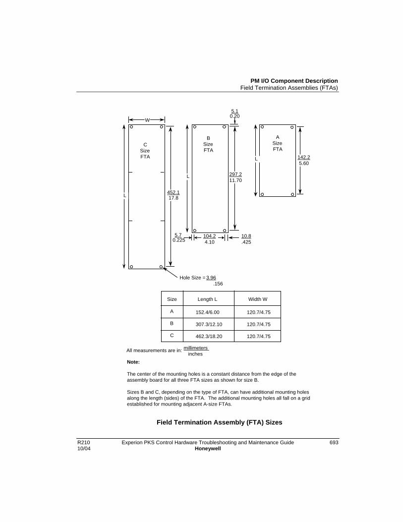
PM I/O Component DescriptionField Termination Assemblies (FTAs)
R210 Experion PKS Control Hardware Troubleshooting and Maintenance Guide 69310/04 Honeywell
C Size FTA
Hole Size = 3.96 .156
A
B
C
152.4/6.00
307.3/12.10
462.3/18.20
120.7/4.75
120.7/4.75
120.7/4.75
W
B Size FTA
L
10.8 .425
A Size FTA
L
Length L Width WSize
L
5.70.225
104.2 4.10
5.10.20
All measurements are in: millimeters inches
Note: The center of the mounting holes is a constant distance from the edge of the assembly board for all three FTA sizes as shown for size B. Sizes B and C, depending on the type of FTA, can have additional mounting holes along the length (sides) of the FTA. The additional mounting holes all fall on a grid established for mounting adjacent A-size FTAs.
297.2 11.70
142.2 5.60
17.8452.1
Field Termination Assembly (FTA) Sizes

PM I/O Component DescriptionField Termination Assemblies (FTAs)
694 Experion PKS Control Hardware Troubleshooting and Maintenance Guide R210Honeywell 10/04
FTA Mounting
The FTAs are installed at the rear or front of a dual access cabinet on one or more FTAmounting channels. In a single access cabinet, the FTAs are mounted on FTA mountingchannels at the front of the cabinet. The FTA mounting channels also function as cableand wiring channels, or troughs. The standard and galvanically isolated FTAs must notbe mounted on the same FTA mounting channel. Mounting both types of FTAs on thesame FTA mounting channel is an intrinsic safety violation because their field wiringwill be routed together. See Installing Standard FTAsin the Control HardwareInstallation Guide for additional information on FTA insallation.
Vertical orientation
Standard and galvanically isolated FTAs are mounted on vertically oriented 3-foot longFTA mounting channel segments; however, Standard and galvanically isolated FTAsmust not be mounted on the same FTA mounting channels.
Galvanically isolated FTAs can be mounted on an FTA mounting channel that is aboveor below an FTA mounting channel that has standard FTAs mounted on it, but the fieldwiring must never be routed in the standard FTA’s channel.

PM I/O Component DescriptionFTA Mounting Channels
R210 Experion PKS Control Hardware Troubleshooting and Maintenance Guide 69510/04 Honeywell
FTA Mounting ChannelsFTA mounting channels are used to mount the FTAs and to organize and separate thefield wiring and IOP to FTA cables.
The FTAs are installed on FTA mounting channels that are located in the front of a singleaccess control cabinet, and in the rear or front of a dual access cabinet.
The number of FTA mounting channels that can be accommodated in a control cabinet isdependent upon whether the cabinet is single access or dual access, and whether standardor wide vertically orientated FTA mounting channels are installed.
Optionally, galvanically isolated FTAs can be mounted on horizontally oriented FTAmounting channels.
Vertical FTA Mounting Channels
Vertical FTA mounting channels are available in two sizes, standard and wide, to betteraccommodate the amount of process control wiring that connects to the FTAs. The FTAmounting channels provide both a mounting surface for the FTAs and dual channels(troughs) to route the IOP to FTA cabling, and the process control wiring.
When standard FTAs are mounted on the FTA mounting channel, the IOP to FTA orPower Distribution Assembly cabling is routed in the right channel and the processcontrol wiring is routed in the left channel. The opposite is true when galvanicallyisolated FTAs are mounted on the FTA mounting channel because the vertical orientationof the FTA mounting channel is reversed.
Horizontal FTA Mounting Channels
Horizontal FTA mounting channels can be installed when galvanically isolated FTAs aremounted in the cabinet. Only galvanically isolated FTAs are mounted on the horizontalFTA mounting channels. They are approximately 61 centimeters (24 inches) long and upto eight horizontal FTA mounting channels can be accommodated on one side of thecabinet.
The IOP to FTA, Power Distribution Assembly, or Marshalling Panel cabling is routed inthe upper channel to the left side of the cabinet, and the process control wiring is routedin the lower channel to the right side of the cabinet.

PM I/O Component DescriptionFTA Mounting Channels
696 Experion PKS Control Hardware Troubleshooting and Maintenance Guide R210Honeywell 10/04
Typical cabinet installation
Single vertical FTA mounting channels, mounted adjacently, can be used to accept FTAsinstalled in the front lower area of a single access cabinet below an IOP card file andpower system as shown in Figure 2.
A typical cabinet layout of FTA mounting channels and standard FTAs in the rear of adual access controller cabinet is shown in Figure 3.
Figure 2 Vertical FTA Mounting Channel Installation – Single AccessCabinet

PM I/O Component DescriptionFTA Mounting Channels
R210 Experion PKS Control Hardware Troubleshooting and Maintenance Guide 69710/04 Honeywell
Figure 3 Typical Vertical FTA Mounting Channel Layout

PM I/O Component DescriptionFTA Wiring Connection Types
698 Experion PKS Control Hardware Troubleshooting and Maintenance Guide R210Honeywell 10/04
FTA Wiring Connection Types
Compression or screw terminals available
Most standard FTA types are available with either compression-type or screw-typeterminal connectors. Some exceptions are the 6-inch Analog Output (AO), 6-inch HighLevel Analog Input (HLAI), 6-inch Low Level Analog Input Multiplexer (LLMux), andthe 6-inch Digital Input Power Distribution Assembly, which are available withcompression-type terminal connectors only. The Remote Hardened Low Level AnalogInput Multiplexer (RHMUX) is available only with screw-type terminal connectors. Thenumber of terminals for both the compression-type and screw-type terminal connectorcan vary depending on the type of standard FTA.
All galvanically isolated FTAs are available with both crimp pin-type and compression-type terminal connectors. The Marshalling Panel and Combiner Panel are available onlywith screw-type terminals.

PM I/O Component DescriptionFTA Wiring Connection Types
R210 Experion PKS Control Hardware Troubleshooting and Maintenance Guide 69910/04 Honeywell
FTA compression-type terminal connector
The following figure is an illustration of a typical compression-type terminal connectorconnection to a standard FTA.
Typical FTA Compression Terminal Connector

PM I/O Component DescriptionFTA Wiring Connection Types
700 Experion PKS Control Hardware Troubleshooting and Maintenance Guide R210Honeywell 10/04
FTA fixed screw terminal connector
The following figure illustrates a typical fixed screw-type terminal connector as it wouldappear on a standard FTA.
Typical FTA Fixed Screw Terminal Connector

PM I/O Component DescriptionFTA Wiring Connection Types
R210 Experion PKS Control Hardware Troubleshooting and Maintenance Guide 70110/04 Honeywell
FTA removable screw-type connectorThe following figure illustrates a typical removable screw-type terminal connector.
Typical FTA Removable Screw Terminal Connector
Galvanic Isolation Module connectors
Crimp pin-type and compression-type terminal connectors are available for thegalvanically isolated FTAs. Terminal connectors on the Galvanic Isolation Moduleshave six terminals. Depending on the type of terminal connector, the terminals acceptsize 0.3 to 3.5 mm2 (12 to 22 AWG) wiring.
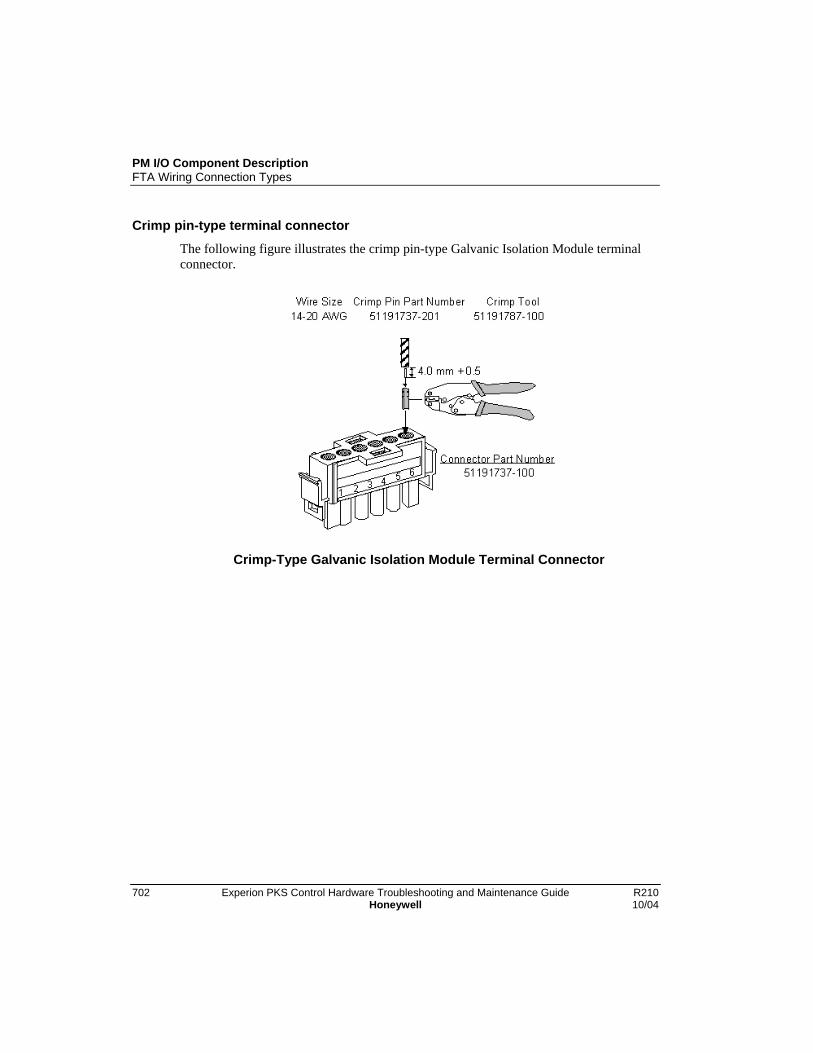
PM I/O Component DescriptionFTA Wiring Connection Types
702 Experion PKS Control Hardware Troubleshooting and Maintenance Guide R210Honeywell 10/04
Crimp pin-type terminal connector
The following figure illustrates the crimp pin-type Galvanic Isolation Module terminalconnector.
Crimp-Type Galvanic Isolation Module Terminal Connector

PM I/O Component DescriptionFTA Wiring Connection Types
R210 Experion PKS Control Hardware Troubleshooting and Maintenance Guide 70310/04 Honeywell
Compression-type terminal connector
The following figure illustrates the compression-type Galvanic Isolation Module terminalconnector.
Compression-Type Galvanic Isolation Module Terminal Connector
PM I/O Component DescriptionPower Systems
704 Experion PKS Control Hardware Troubleshooting and Maintenance Guide R210Honeywell 10/04
Power SystemsThe Power Systems for PM I/O provide 24 Vdc power for operation of all controllerchassis, IOP cards, FTAs, a nominal 3.6 Vdc battery output for backup of the IOPmemory circuits, and a nominal 0.25 ampere, 6 Vac output for operation of a LLAI linefrequency noise cancellation clock circuit. There are two types of power systems. Theyare listed below.
Power System Type Description
Standard Power System(Model MU/MC-PSSX04)
Power system with optional redundantpower supply module and battery backupmodule.
AC Only Power System (optional) This power system is intended for usewith an uninterruptible ac power source.It does not provide a battery backupoption for continuous operation in theevent of a primary power loss.
Standard Power SystemThe standard power system has many versatile attributes that include:
• An optional redundant Power Supply Module (model MU-PSRX04)
• Either 120 Vac or 240 Vac input power. A single or dual source of input powercan be connected when the optional redundant power supply module option isimplemented
• Single and redundant power supply module failure detection
• CMOS memory NiCad battery backup (3.6 Vdc) with failure detection
• An optional 48 Vdc Battery Backup Module (model MU-PSRB04) with adisconnect connector that provides continuous equipment in the event of aprimary power loss
• Provides fused ac power for 4 cabinet fan assemblies
48 volt battery backup time duration
The 48 volt battery backup time duration for a redundant control cabinet containing 40IOPs (40 nonredundant or 20 redundant pairs) is approximately 20 minutes for a fullycharged battery.

PM I/O Component DescriptionPower Systems
R210 Experion PKS Control Hardware Troubleshooting and Maintenance Guide 70510/04 Honeywell
CMOS backup time duration
The following CMOS backup durations are defined for a redundant control cabinetcontaining 40 IOPs (40 nonredundant or 20 redundant pairs). The time duration dependson which type of power system exists in the specific control cabinet.
Standard Power System = 45 hours (uses three C size NiCad batteries)AC Only power system = 55 hours, with new batteries (use three alkaline batteries)
The current draw of each IOP is almost negligible.
Standard Power System
The following figure illustrates the standard power system configuration. The powersystem’s connectors, terminal strips, battery and fuse holders are an integral part of thepower system backpanel.
There are twelve 24 Vdc power distribution output connectors, four cabinet fan assemblypower connectors with associated fuse holders, and a NiCad battery holder on thebackpanel. Sets of terminals provide alarm signals (for external alarm mechanisms) fromeach power supply module and the CMOS battery backup. The alarm signals arenormally wired in series to a 24 Vdc Digital Input FTA to notify the system when apower supply module fails.
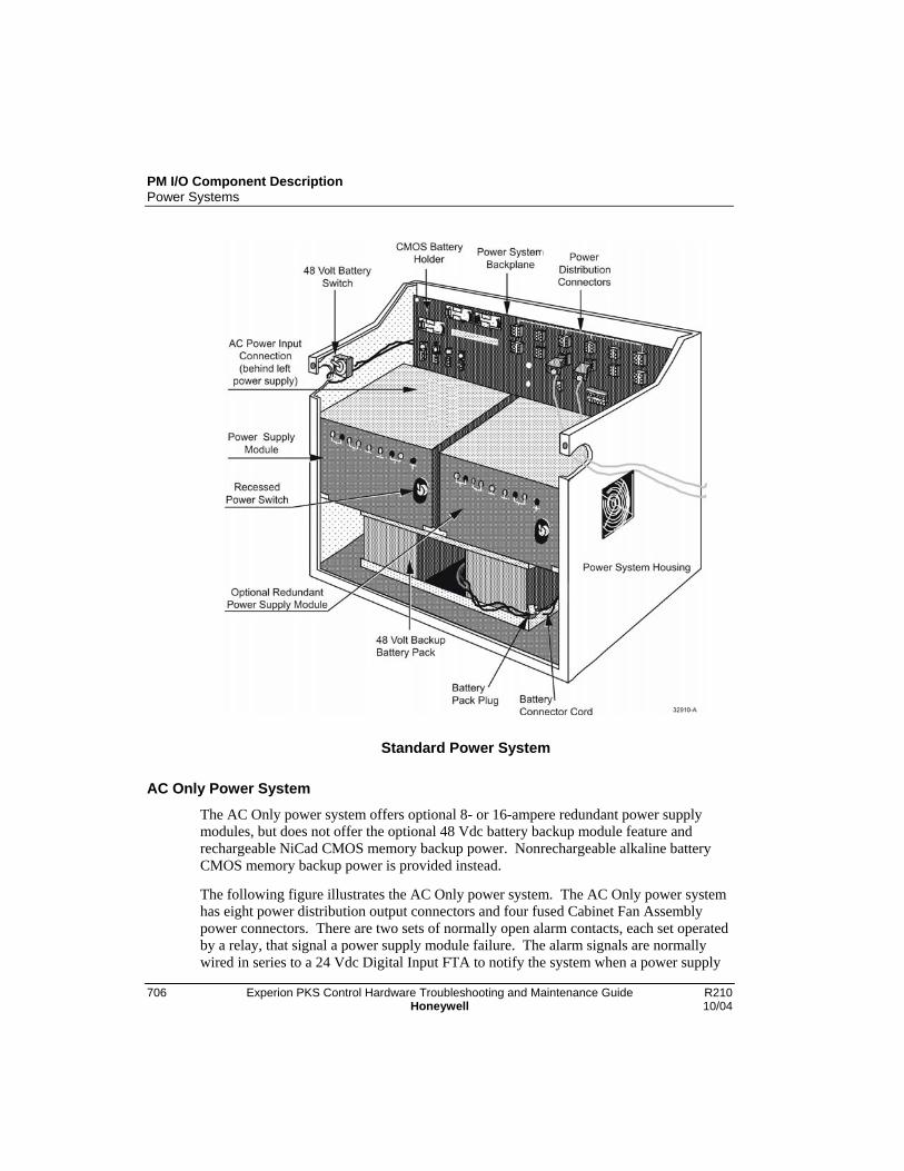
PM I/O Component DescriptionPower Systems
706 Experion PKS Control Hardware Troubleshooting and Maintenance Guide R210Honeywell 10/04
Standard Power System
AC Only Power System
The AC Only power system offers optional 8- or 16-ampere redundant power supplymodules, but does not offer the optional 48 Vdc battery backup module feature andrechargeable NiCad CMOS memory backup power. Nonrechargeable alkaline batteryCMOS memory backup power is provided instead.
The following figure illustrates the AC Only power system. The AC Only power systemhas eight power distribution output connectors and four fused Cabinet Fan Assemblypower connectors. There are two sets of normally open alarm contacts, each set operatedby a relay, that signal a power supply module failure. The alarm signals are normallywired in series to a 24 Vdc Digital Input FTA to notify the system when a power supply

PM I/O Component DescriptionPower Systems
R210 Experion PKS Control Hardware Troubleshooting and Maintenance Guide 70710/04 Honeywell
module fails. Two LED indicators, mounted on the AC Only AC/DC DistributionAssembly, offer a visual indication of a power supply module failure when the LED isextinguished.
Figure 4 AC Only Power System

PM I/O Component DescriptionPower Distribution
708 Experion PKS Control Hardware Troubleshooting and Maintenance Guide R210Honeywell 10/04
Power DistributionPower distribution is illustrated in Figure 5.
AC input power connections are located on the lower left side of the backpanel, behindthe left power supply module, in the standard power system. Primary and redundantterminals can be wired in parallel from a single power line source, or wired separatelyfrom two power line sources. See Figure 6.
Figure 5 Power Distribution
AC Only Power System ac power
AC input power connections to the AC Only power system are made to the AC Inputterminal strips at the left side of the AC/DC Distribution board as shown in Figure 4.The upper AC Input terminal strip powers the optional redundant power supply module,and the lower AC Input terminal strip powers the primary power supply module. Theprimary and redundant terminals can be wired in parallel from a single power line source,or wired separately from two power line sources.

PM I/O Component DescriptionPower Distribution
R210 Experion PKS Control Hardware Troubleshooting and Maintenance Guide 70910/04 Honeywell
Battery Backup Module
The Battery Backup Module used to power the 24 Vdc power supply modules is a 48Vdc lead acid battery that provides backup power for approximately 25 minutes with afull charge. The charging circuit is active in both power supply modules whenever acpower is available to the power supply module(s). At least one power supply modulemust be present to allow the battery to supply power to the card files.
48 Volt Battery switch
A 48 Volt Battery switch that is located at the left side of the standard power systemchassis provides a means of preventing the power supply modules from discharging thebattery backup module when ac power is removed from one or both power supplymodules. Placing the switch in the off position disconnects the battery to power supplymodule paths.
No battery backup (Standard Power System)
When there is no battery backup, a battery backup failure is reported unless the zero-ohmresistor jumpers, W1 and W2, located next to the power supply module connectors, arecut. This is done at the factory before shipping. If a battery backup is later installed, theconnections must be restored. Figure 6 is a view of the standard power systembackpanel.
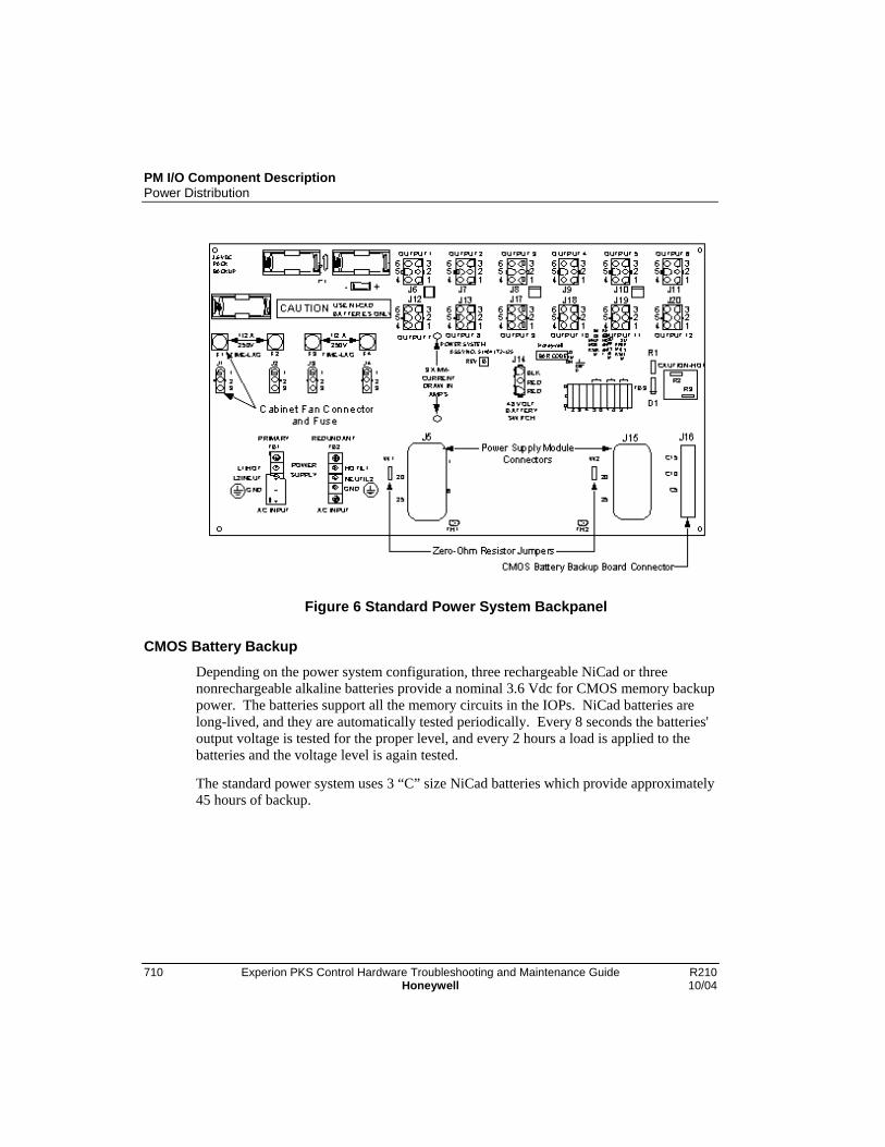
PM I/O Component DescriptionPower Distribution
710 Experion PKS Control Hardware Troubleshooting and Maintenance Guide R210Honeywell 10/04
Figure 6 Standard Power System Backpanel
CMOS Battery Backup
Depending on the power system configuration, three rechargeable NiCad or threenonrechargeable alkaline batteries provide a nominal 3.6 Vdc for CMOS memory backuppower. The batteries support all the memory circuits in the IOPs. NiCad batteries arelong-lived, and they are automatically tested periodically. Every 8 seconds the batteries'output voltage is tested for the proper level, and every 2 hours a load is applied to thebatteries and the voltage level is again tested.
The standard power system uses 3 “C” size NiCad batteries which provide approximately45 hours of backup.

PM I/O Component DescriptionPower Distribution
R210 Experion PKS Control Hardware Troubleshooting and Maintenance Guide 71110/04 Honeywell
Standard Power System
Refer to Figure 6 for the location of the CMOS battery backup assembly matingconnector on the backpanel.
The standard power system configuration has NiCad batteries located at the upper left ofthe power system chassis backpanel, and the supporting CMOS battery backup assemblyis inserted into a connector at the lower right-hand side of the backpanel. The rightpower supply module must be removed to view the assembly. The assembly providesboth charging circuitry and a monitoring circuitry for failure alarm reporting. See Figure7 for an illustration of the latest version of CMOS battery backup assembly.
Figure 7 CMOS Battery Backup Assembly (Standard Power System)
ATTENTION
A bad batteries alarm occurs when the CMOS batteries are discharged.
AC Only Power System
The AC Only power system uses alkaline batteries which must be replaced frequently.The three alkaline batteries are located at the center of the AC/DC Distribution Assemblyas shown in Figure 4. No charging circuitry or monitoring circuitry for failure alarmreporting exists. A new set of batteries will provide approximately 55 hours of backuptime.

PM I/O Component Description24 Vdc Power Distribution
712 Experion PKS Control Hardware Troubleshooting and Maintenance Guide R210Honeywell 10/04
24 Vdc Power Distribution
Dual power distribution cables
To improve reliability, redundant 24 Vdc distribution to the card files is always providedby two power distribution cables.
Standard Power System
The standard power system provides twelve 6-pin connectors located on its backpanel.This allows a greater flexibility in providing power to IOP card files, Digital Input PowerDistribution Assemblies and Galvanic Isolation Power Distribution Assemblies.
AC Only Power System
The AC Only power system provides eight 6-pin connectors located on the AC/DCDistribution Assembly that will redundantly power three card files and a Digital InputPower Distribution Assembly or Galvanic Isolation Power Distribution Assembly.
Typical cabinet power distribution
Figure 8 illustrates the typical 24 Vdc cabinet power distribution to the card files, DigitalInput Power Distribution Assembly, and Galvanic Isolation Power DistributionAssembly for the various power system configurations.

PM I/O Component Description24 Vdc Power Distribution
R210 Experion PKS Control Hardware Troubleshooting and Maintenance Guide 71310/04 Honeywell
Figure 8 Typical Cabinet 24 Vdc Power Distribution

PM I/O Component DescriptionCabinet Fan Assembly
714 Experion PKS Control Hardware Troubleshooting and Maintenance Guide R210Honeywell 10/04
Cabinet Fan AssemblyFused 0.5 A 120 Vac or 240 Vac power is provided by the power system for cabinet fanassembly operation.
Up to four cabinet fan assemblies can be powered by the 120 Vac or 240 Vac providedby the four 3-pin connectors of the standard or AC Only power system configurations.The connectors and fuses are located at the left side of the standard power systembackpanel (as shown in Figure 6) and at the bottom of the AC Only power systemAC/DC Distribution assembly. See Figure 4.
Optional Cabinet Fan assembly
An optional cabinet fan assembly has an LED indicator that indicates normal operation ofboth fans, and an alarm signal, represented by normally open contacts, is available at aterminal strip, TB1. The contacts are closed when the cabinet fan assembly is operatingnormally. The operation of the cabinet fan assembly can be monitored by a 24 VdcDigital Input FTA, by providing the alarm 24 Vdc signal source from the FTA andreturning it to the FTA through the alarm contacts.

PM I/O Component DescriptionLLAI Line Frequency Clock Voltage
R210 Experion PKS Control Hardware Troubleshooting and Maintenance Guide 71510/04 Honeywell
LLAI Line Frequency Clock VoltageThe power system provides a nominal 6 Vac half-wave rectified phase reference signal tothe IOP card file assemblies through the power cable. A pluggable solid-state opticalcoupler module, U1, on each type of card file backpanel generates this line frequencyphase reference signal. It is located at the bottom right of a 7-slot card file backpanel andin a similar position on the 15 slot card file. Its 6 Vac output is routed to the Low LevelAnalog Input (LLAI) IOPs through power cables and card file backpanels. The signal isused by the IOPs to improve the common and normal mode noise rejection ratio.
Standard Power System
In the standard power system configuration, the power supply module located at the leftside of the assembly is the source of the line frequency phase reference signal. If the leftpower supply module is removed, the LLAI IOPs in the same cabinet will report a Softfailure and continue to operate, but at lesser degree of accuracy.
AC Only Power System
The line frequency phase reference signal in the AC Only power system configuration isnot dependent upon the presence of the left or right side power supply modules, since aconstant voltage is supplied by the AC/DC Distribution Assembly.

PM I/O Component Description24 Vdc Fuse Protection
716 Experion PKS Control Hardware Troubleshooting and Maintenance Guide R210Honeywell 10/04
24 Vdc Fuse Protection
Card file fusing
Fuse protection is provided for the IOP card files. The following protection philosophyapplies for both the 7-Slot and 15-Slot IOP card files.
• The individual IOP card and an associated standard FTA are protected by acommon fast-action fuse that is located on the backpanel. The fuse has a 2 Arating.
• In addition to the 2 A protection, each individual IOP card has fast-action 0.5 Afuse protection that is located on the card. The fast-action 0.5 A fuse is solderedin place and is not field replaceable. You must replace the IOP card.
• A fast-action 2.0 A fuse protects the LLAI optical coupler module on backpanelU1. It generates the line frequency phase reference signal that is used by LLAIIOPs.
Fuse removal
A Honeywell designed fusepuller is generally needed for extracting and inserting fuses inthe IOP backpanels because of the restricted space between components. The Honeywellpart number is 51190586-100.
The fusepuller is comprised of three parts; an inner barrel that grasps the fuse, an end capthat is attached one end of the inner barrel, and an outer barrel in which the inner barrelmoves.
The following extraction and insertion procedures should aid in the use of the fusepuller.
Fuse extraction
Step Action
1 Hold the outer barrel of the fusepuller with the fingers of one hand anddepress the fusepuller’s end cap with your other hand.
2 Place the protruding end of the inner barrel around the fuse. The fusepullermust be perpendicular to the backpanel.
3 Release the end cap while still holding the outer barrel.
4 Move the outer barrel towards the backpanel. The greater the movement, thegreater the gripping force will be on the fuse.
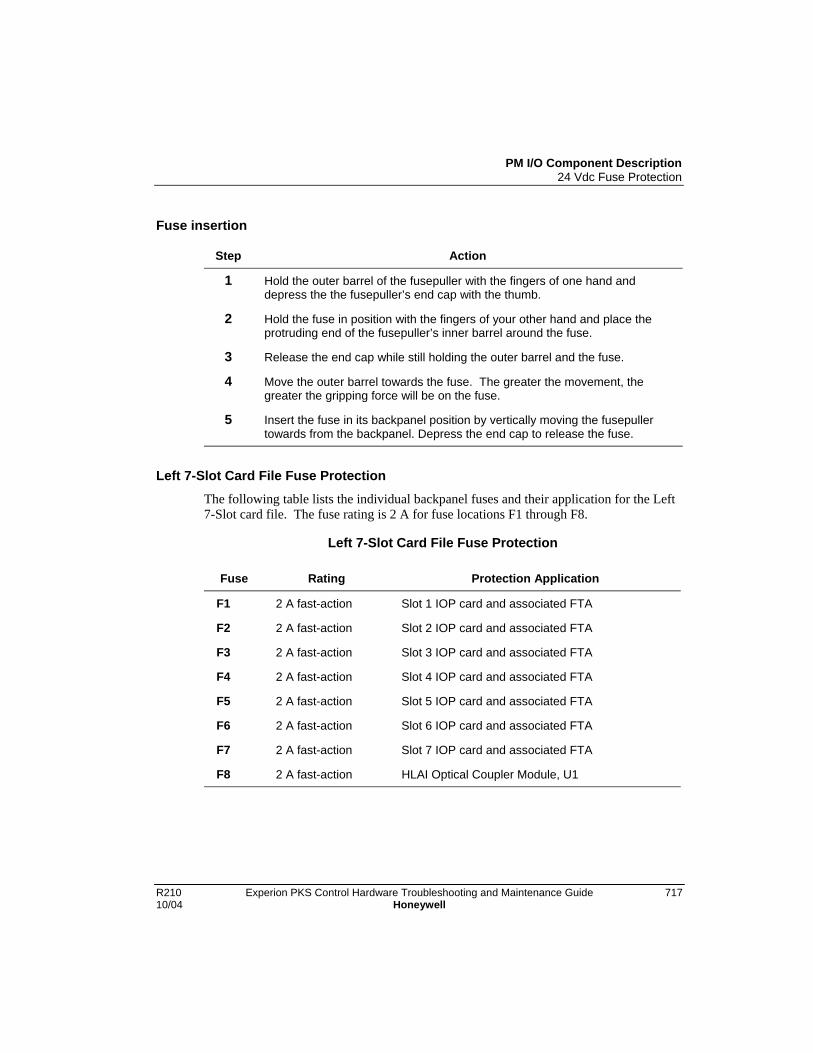
PM I/O Component Description24 Vdc Fuse Protection
R210 Experion PKS Control Hardware Troubleshooting and Maintenance Guide 71710/04 Honeywell
Fuse insertion
Step Action
1 Hold the outer barrel of the fusepuller with the fingers of one hand anddepress the the fusepuller’s end cap with the thumb.
2 Hold the fuse in position with the fingers of your other hand and place theprotruding end of the fusepuller’s inner barrel around the fuse.
3 Release the end cap while still holding the outer barrel and the fuse.
4 Move the outer barrel towards the fuse. The greater the movement, thegreater the gripping force will be on the fuse.
5 Insert the fuse in its backpanel position by vertically moving the fusepullertowards from the backpanel. Depress the end cap to release the fuse.
Left 7-Slot Card File Fuse Protection
The following table lists the individual backpanel fuses and their application for the Left7-Slot card file. The fuse rating is 2 A for fuse locations F1 through F8.
Left 7-Slot Card File Fuse Protection
Fuse Rating Protection Application
F1 2 A fast-action Slot 1 IOP card and associated FTA
F2 2 A fast-action Slot 2 IOP card and associated FTA
F3 2 A fast-action Slot 3 IOP card and associated FTA
F4 2 A fast-action Slot 4 IOP card and associated FTA
F5 2 A fast-action Slot 5 IOP card and associated FTA
F6 2 A fast-action Slot 6 IOP card and associated FTA
F7 2 A fast-action Slot 7 IOP card and associated FTA
F8 2 A fast-action HLAI Optical Coupler Module, U1
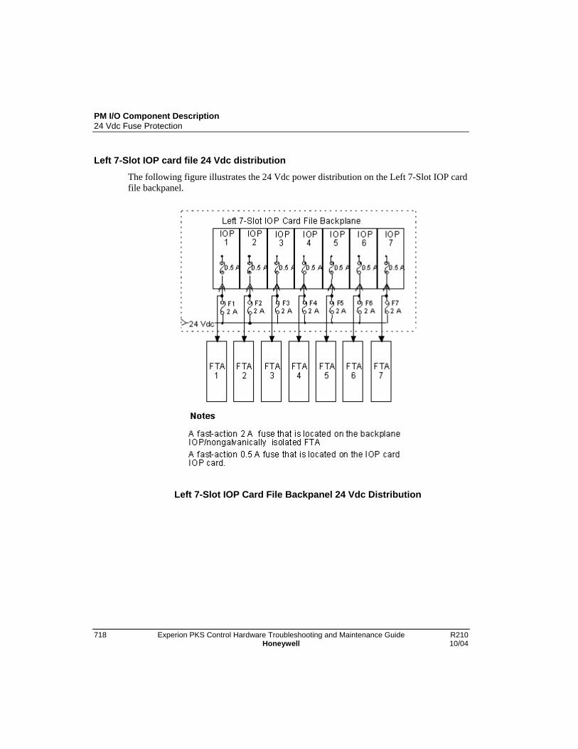
PM I/O Component Description24 Vdc Fuse Protection
718 Experion PKS Control Hardware Troubleshooting and Maintenance Guide R210Honeywell 10/04
Left 7-Slot IOP card file 24 Vdc distribution
The following figure illustrates the 24 Vdc power distribution on the Left 7-Slot IOP cardfile backpanel.
Left 7-Slot IOP Card File Backpanel 24 Vdc Distribution
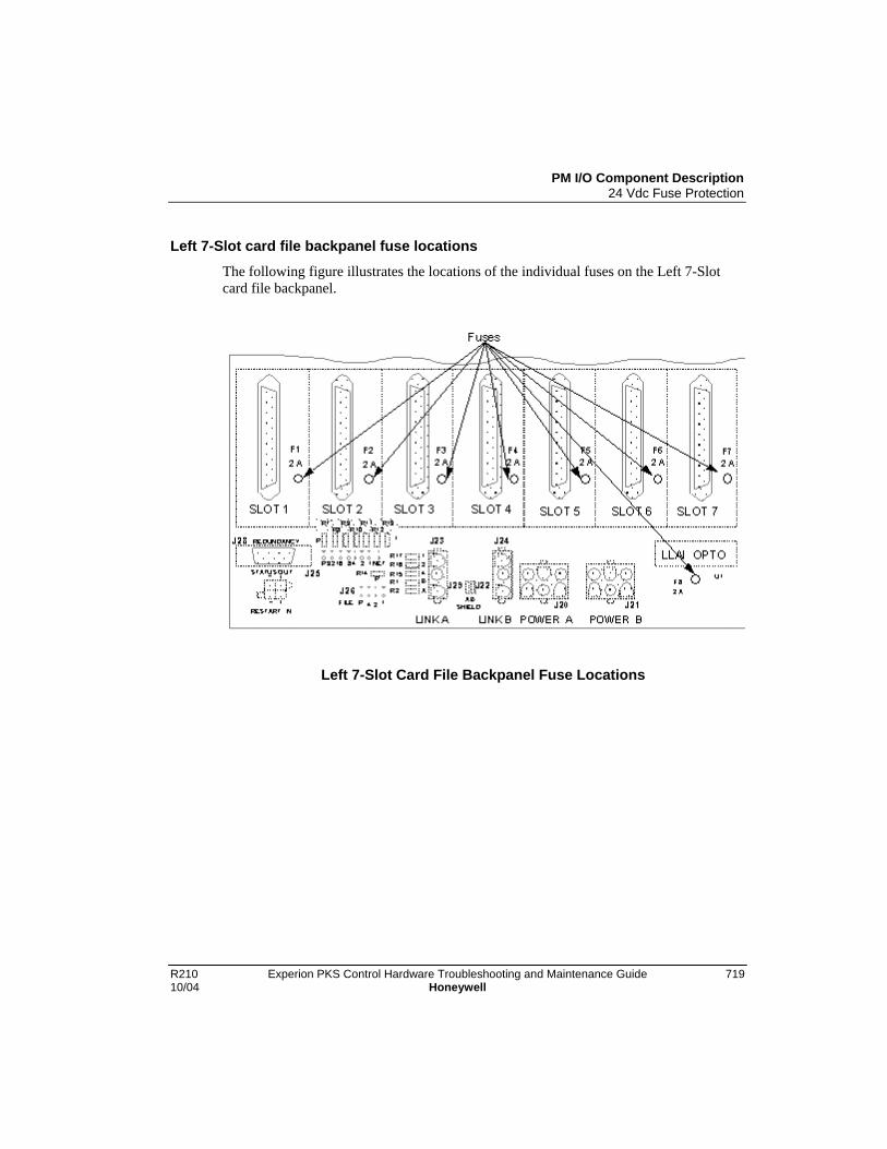
PM I/O Component Description24 Vdc Fuse Protection
R210 Experion PKS Control Hardware Troubleshooting and Maintenance Guide 71910/04 Honeywell
Left 7-Slot card file backpanel fuse locations
The following figure illustrates the locations of the individual fuses on the Left 7-Slotcard file backpanel.
Left 7-Slot Card File Backpanel Fuse Locations
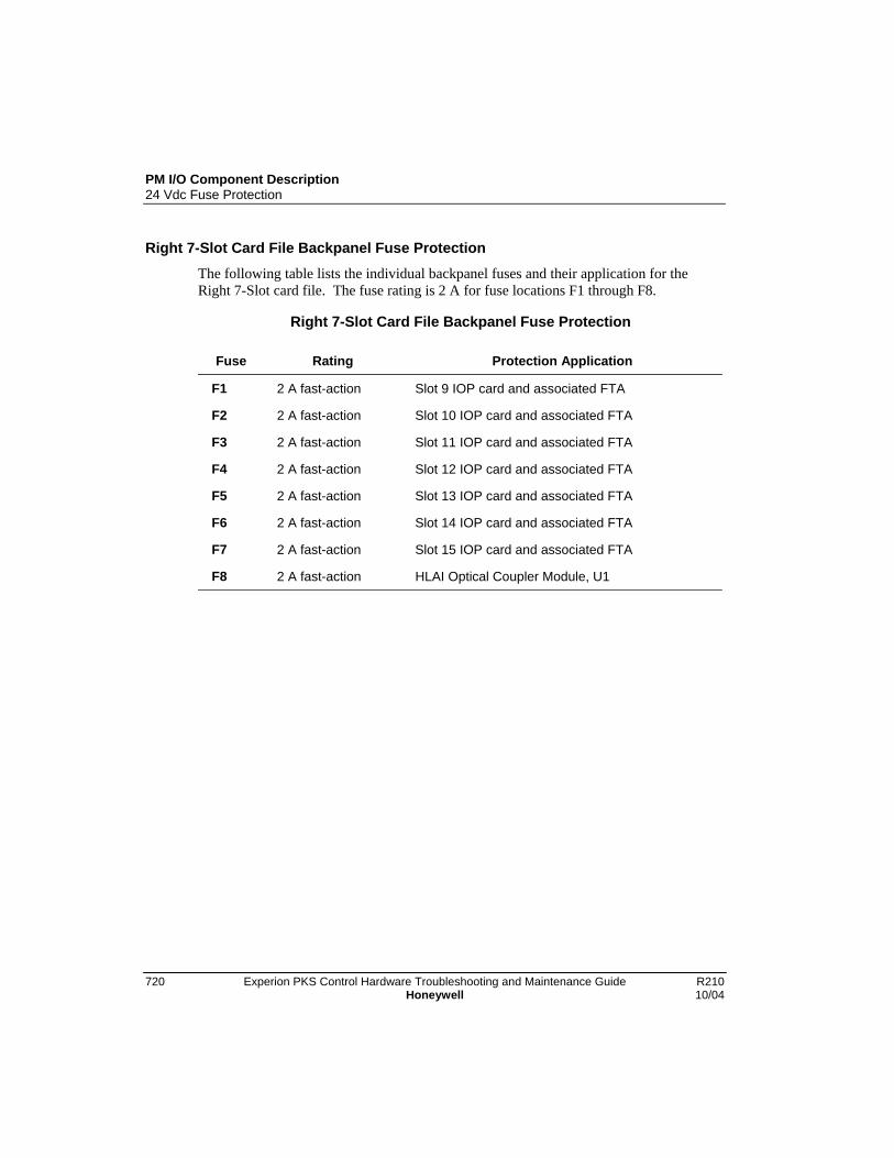
PM I/O Component Description24 Vdc Fuse Protection
720 Experion PKS Control Hardware Troubleshooting and Maintenance Guide R210Honeywell 10/04
Right 7-Slot Card File Backpanel Fuse Protection
The following table lists the individual backpanel fuses and their application for theRight 7-Slot card file. The fuse rating is 2 A for fuse locations F1 through F8.
Right 7-Slot Card File Backpanel Fuse Protection
Fuse Rating Protection Application
F1 2 A fast-action Slot 9 IOP card and associated FTA
F2 2 A fast-action Slot 10 IOP card and associated FTA
F3 2 A fast-action Slot 11 IOP card and associated FTA
F4 2 A fast-action Slot 12 IOP card and associated FTA
F5 2 A fast-action Slot 13 IOP card and associated FTA
F6 2 A fast-action Slot 14 IOP card and associated FTA
F7 2 A fast-action Slot 15 IOP card and associated FTA
F8 2 A fast-action HLAI Optical Coupler Module, U1

PM I/O Component Description24 Vdc Fuse Protection
R210 Experion PKS Control Hardware Troubleshooting and Maintenance Guide 72110/04 Honeywell
Right 7-Slot IOP card file 24 Vdc distribution
The following figure illustrates the 24 Vdc power distribution on the Right 7-Slot IOPcard file backpanel.
Right 7-Slot IOP Card File Backpanel 24 Vdc Distribution
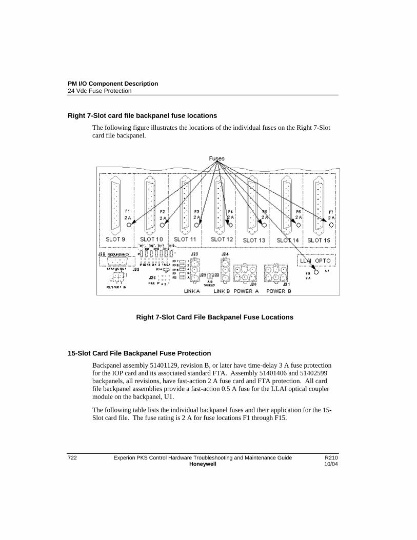
PM I/O Component Description24 Vdc Fuse Protection
722 Experion PKS Control Hardware Troubleshooting and Maintenance Guide R210Honeywell 10/04
Right 7-Slot card file backpanel fuse locations
The following figure illustrates the locations of the individual fuses on the Right 7-Slotcard file backpanel.
Right 7-Slot Card File Backpanel Fuse Locations
15-Slot Card File Backpanel Fuse Protection
Backpanel assembly 51401129, revision B, or later have time-delay 3 A fuse protectionfor the IOP card and its associated standard FTA. Assembly 51401406 and 51402599backpanels, all revisions, have fast-action 2 A fuse card and FTA protection. All cardfile backpanel assemblies provide a fast-action 0.5 A fuse for the LLAI optical couplermodule on the backpanel, U1.
The following table lists the individual backpanel fuses and their application for the 15-Slot card file. The fuse rating is 2 A for fuse locations F1 through F15.
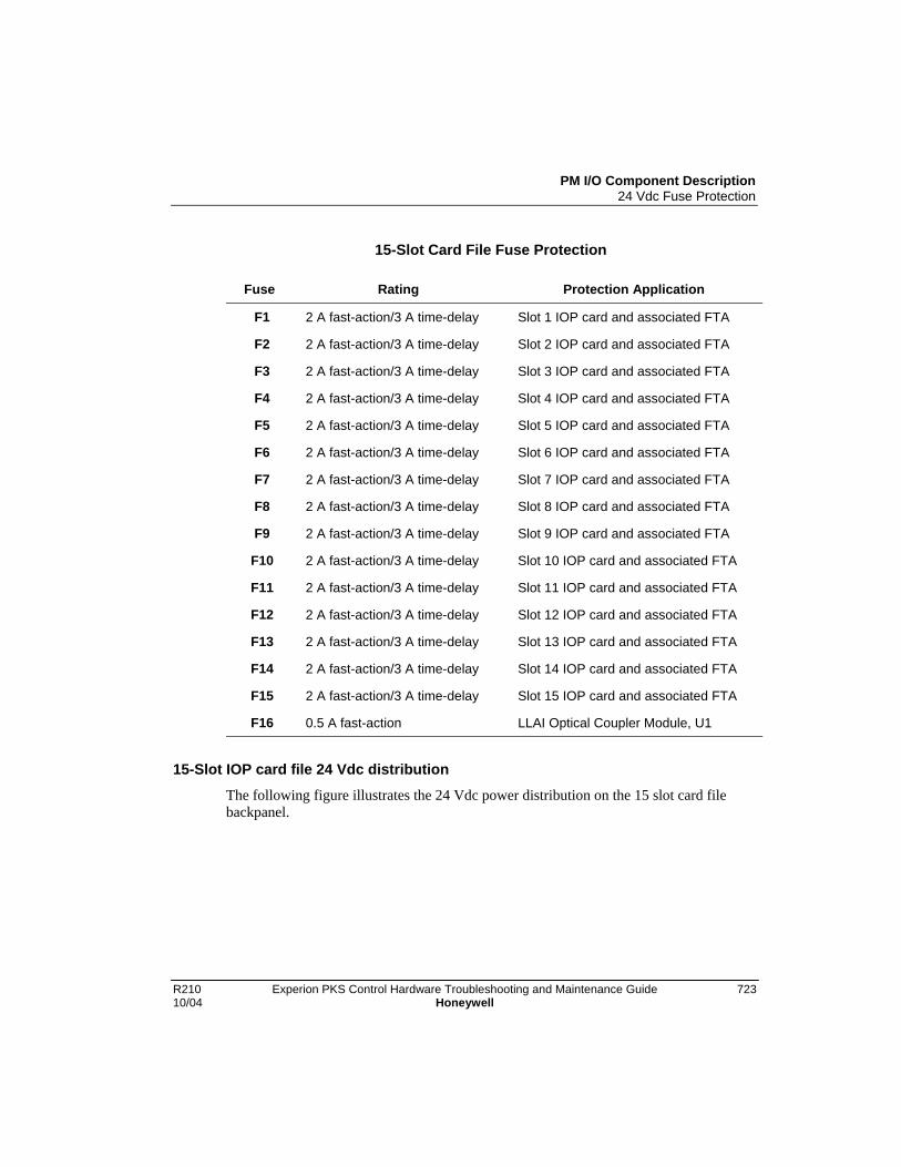
PM I/O Component Description24 Vdc Fuse Protection
R210 Experion PKS Control Hardware Troubleshooting and Maintenance Guide 72310/04 Honeywell
15-Slot Card File Fuse Protection
Fuse Rating Protection Application
F1 2 A fast-action/3 A time-delay Slot 1 IOP card and associated FTA
F2 2 A fast-action/3 A time-delay Slot 2 IOP card and associated FTA
F3 2 A fast-action/3 A time-delay Slot 3 IOP card and associated FTA
F4 2 A fast-action/3 A time-delay Slot 4 IOP card and associated FTA
F5 2 A fast-action/3 A time-delay Slot 5 IOP card and associated FTA
F6 2 A fast-action/3 A time-delay Slot 6 IOP card and associated FTA
F7 2 A fast-action/3 A time-delay Slot 7 IOP card and associated FTA
F8 2 A fast-action/3 A time-delay Slot 8 IOP card and associated FTA
F9 2 A fast-action/3 A time-delay Slot 9 IOP card and associated FTA
F10 2 A fast-action/3 A time-delay Slot 10 IOP card and associated FTA
F11 2 A fast-action/3 A time-delay Slot 11 IOP card and associated FTA
F12 2 A fast-action/3 A time-delay Slot 12 IOP card and associated FTA
F13 2 A fast-action/3 A time-delay Slot 13 IOP card and associated FTA
F14 2 A fast-action/3 A time-delay Slot 14 IOP card and associated FTA
F15 2 A fast-action/3 A time-delay Slot 15 IOP card and associated FTA
F16 0.5 A fast-action LLAI Optical Coupler Module, U1
15-Slot IOP card file 24 Vdc distribution
The following figure illustrates the 24 Vdc power distribution on the 15 slot card filebackpanel.
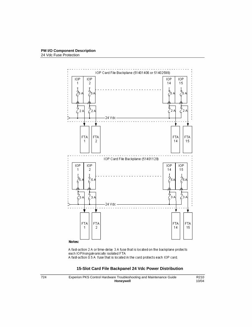
PM I/O Component Description24 Vdc Fuse Protection
724 Experion PKS Control Hardware Troubleshooting and Maintenance Guide R210Honeywell 10/04
15-Slot Card File Backpanel 24 Vdc Power Distribution

PM I/O Component Description24 Vdc Fuse Protection
R210 Experion PKS Control Hardware Troubleshooting and Maintenance Guide 72510/04 Honeywell
15 Slot card file backpanel fuse locations
The following figure illustrates the locations of the individual fuses on the 15 slot cardfile backpanel.
15-Slot Card File Backpanel Fuse Locations

PM I/O Component Description24 Vdc Fuse Protection
726 Experion PKS Control Hardware Troubleshooting and Maintenance Guide R210Honeywell 10/04
FTA fuse protection
Some individual FTAs may have fuse protection on the assembly. In general, outputtype FTAs are fused, but not exclusively. Fuse information for the individual FTAs canbe found in Appendixes C and D in the Control Hardware Installation Guide.
Cabinet Fan assembly fuse protection
Each Cabinet Fan Assembly is protected by fast-action 0.5 A fuse located on the powersystem backpanel assembly. A control cabinet can contain two individually fused FanAssemblies. Both the Standard, and AC Only power system configurations providefused circuits for four fan assemblies. Refer to Figure 4 for the locations of the FanAssembly fuses.
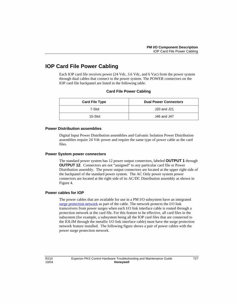
PM I/O Component DescriptionIOP Card File Power Cabling
R210 Experion PKS Control Hardware Troubleshooting and Maintenance Guide 72710/04 Honeywell
IOP Card File Power CablingEach IOP card file receives power (24 Vdc, 3.6 Vdc, and 6 Vac) from the power systemthrough dual cables that connect to the power system. The POWER connectors on theIOP card file backpanel are listed in the following table.
Card File Power Cabling
Card File Type Dual Power Connectors
7-Slot J20 and J21
15-Slot J46 and J47
Power Distribution assemblies
Digital Input Power Distribution assemblies and Galvanic Isolation Power Distributionassemblies require 24 Vdc power and require the same type of power cable as the cardfiles.
Power System power connectors
The standard power system has 12 power output connectors, labeled OUTPUT 1 throughOUTPUT 12. Connectors are not “assigned” to any particular card file or PowerDistribution assembly. The power output connectors are located at the upper right side ofthe backpanel of the standard power system. The AC Only power system powerconnectors are located at the right side of its AC/DC Distribution assembly as shown inFigure 4.
Power cables for IOP
The power cables that are available for use in a PM I/O subsystem have an integratedsurge protection network as part of the cable. The network protects the I/O linktransceivers from power surges when each I/O link interface cable is routed through aprotection network at the card file. For this feature to be effective, all card files in thesubsystem (for example, a subsystem being all the IOP card files that are connected tothe IOLIM through the metallic I/O link interface cable) must have the surge protectionnetwork feature installed. The following figure shows a pair of power cables with thepower surge protection network.
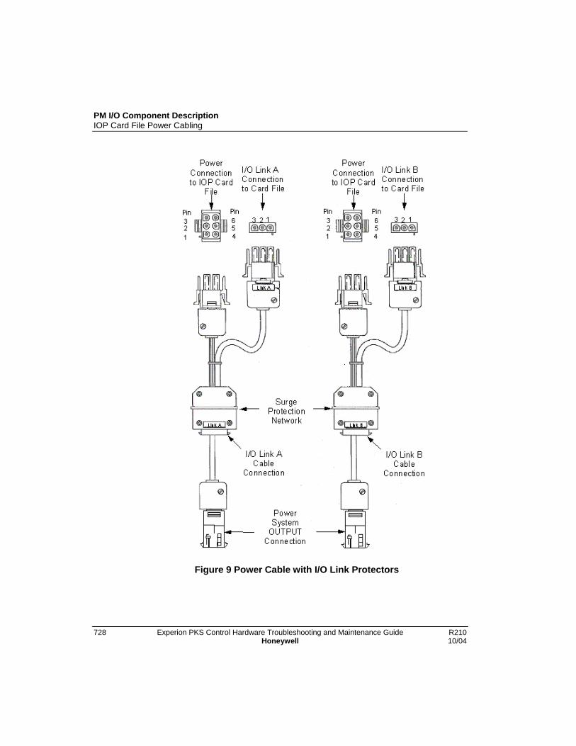
PM I/O Component DescriptionIOP Card File Power Cabling
728 Experion PKS Control Hardware Troubleshooting and Maintenance Guide R210Honeywell 10/04
Figure 9 Power Cable with I/O Link Protectors
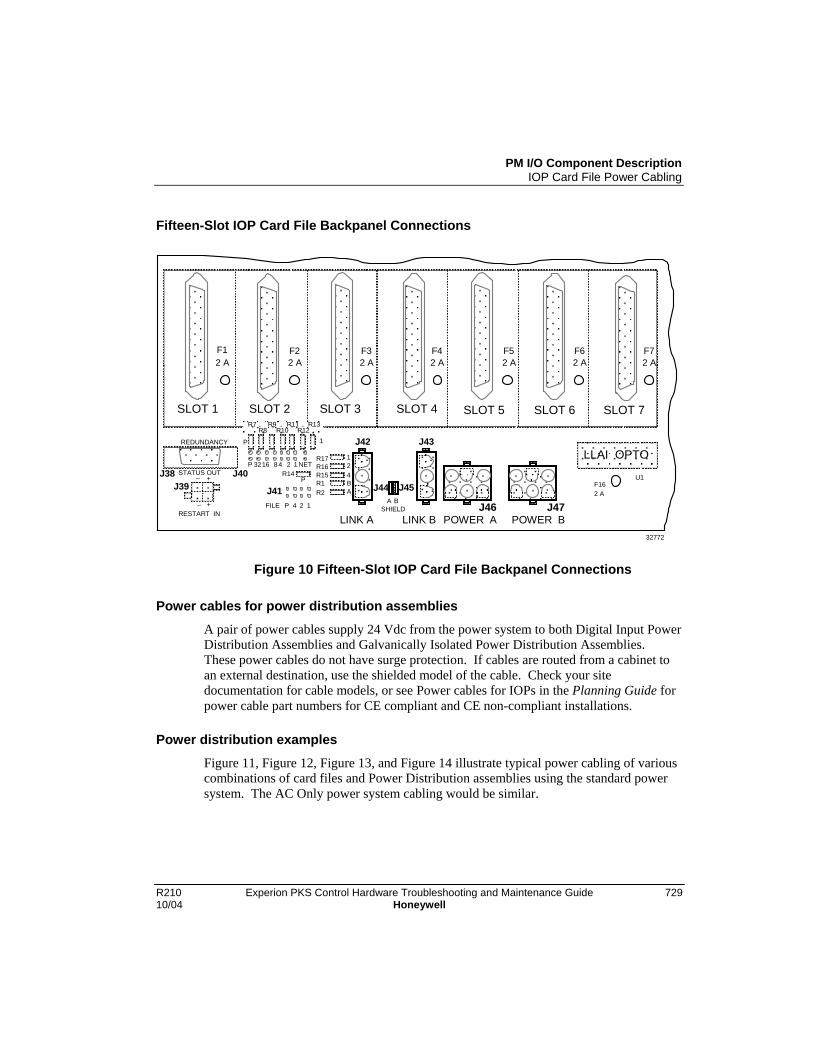
PM I/O Component DescriptionIOP Card File Power Cabling
R210 Experion PKS Control Hardware Troubleshooting and Maintenance Guide 72910/04 Honeywell
Fifteen-Slot IOP Card File Backpanel Connections
32772
R7 R9 R11 R13 R12 R10 R8
F6 2 A
F5 2 A
F4 2 A
F3 2 A
F2 2 A
SLOT 1 SLOT 2 SLOT 3 SLOT 4 SLOT 5 SLOT 6 SLOT 7
REDUNDANCY
STATUS OUT
POWER A POWER B
LLAI OPTO + _
RESTART IN
J38 F16 2 A
U1
J42 J43
J44 J45
LINK A LINK B
J40 J41
P
R14 P
P 32 16 8 4 2 1 NET
FILE P 2 4 1 + _
R17R16R15R1 R2
124BA
A BSHIELD
1
J39 J47J46
F7 2 A
F1 2 A
Figure 10 Fifteen-Slot IOP Card File Backpanel Connections
Power cables for power distribution assemblies
A pair of power cables supply 24 Vdc from the power system to both Digital Input PowerDistribution Assemblies and Galvanically Isolated Power Distribution Assemblies.These power cables do not have surge protection. If cables are routed from a cabinet toan external destination, use the shielded model of the cable. Check your sitedocumentation for cable models, or see Power cables for IOPs in the Planning Guide forpower cable part numbers for CE compliant and CE non-compliant installations.
Power distribution examples
Figure 11, Figure 12, Figure 13, and Figure 14 illustrate typical power cabling of variouscombinations of card files and Power Distribution assemblies using the standard powersystem. The AC Only power system cabling would be similar.

PM I/O Component DescriptionIOP Card File Power Cabling
730 Experion PKS Control Hardware Troubleshooting and Maintenance Guide R210Honeywell 10/04
Power distribution methods
The AC Only power system are limited to eight power output connectors. The eightconnectors provide power for various combinations, depending upon power requirementsof card files, Digital Input Power Distribution assemblies, and Galvanic Isolation PowerDistribution assemblies. Redundant power cabling to each assembly is recommended.However, an exception must be made when three card files, a Digital Input PowerDistribution assembly, and a Galvanic Isolation Power Distribution assembly are presentin the cabinet, since only eight power output connectors are available. The power cablesare then daisy-chained. See Figure 15.
The standard power system provides 12 power output connectors which eliminates theneed to daisy-chain power from one file to file.

PM I/O Component DescriptionIOP Card File Power Cabling
R210 Experion PKS Control Hardware Troubleshooting and Maintenance Guide 73110/04 Honeywell
15-Slot Card File with Power Distribution Assemblies
The following figure illustrates power cabling for a typical PM I/O configuration of asingle 15-Slot card file and Power Distribution assemblies.
Figure 11 15-Slot Card File with Power Distribution Assemblies

PM I/O Component DescriptionIOP Card File Power Cabling
732 Experion PKS Control Hardware Troubleshooting and Maintenance Guide R210Honeywell 10/04
Two 15-Slot Card Files with Power Distribution Assemblies
The following figure illustrates power cabling for a typical PM I/O configuration of two15-Slot card files and two Power Distribution assemblies.
Figure 12 Two 15-Slot Card Files with Power Distribution Assemblies

PM I/O Component DescriptionIOP Card File Power Cabling
R210 Experion PKS Control Hardware Troubleshooting and Maintenance Guide 73310/04 Honeywell
Three 15-Slot Card Files
The following figure illustrates power cabling for a typical PM I/O configuration of three15-Slot card files.
Figure 13 Three 15-Slot Card Files

PM I/O Component DescriptionIOP Card File Power Cabling
734 Experion PKS Control Hardware Troubleshooting and Maintenance Guide R210Honeywell 10/04
Three 15-Slot Card Files with Power Distribution Assemblies
The following figure illustrates power cabling for a typical PM I/O configuration of three15-Slot card files and two Power Distribution assemblies.

PM I/O Component DescriptionIOP Card File Power Cabling
R210 Experion PKS Control Hardware Troubleshooting and Maintenance Guide 73510/04 Honeywell
Figure 14 Three 15-Slot Card Files with Power Distribution Assemblies

PM I/O Component DescriptionIOP Card File Power Cabling
736 Experion PKS Control Hardware Troubleshooting and Maintenance Guide R210Honeywell 10/04
Power Distribution Assemblies for redundant cabling
AC Only Power Systems are limited to eight power output connectors. The followingfigure illustrates how power is distributed when the number of available connectors doesnot meet the total need for redundant cabling.

PM I/O Component DescriptionIOP Card File Power Cabling
R210 Experion PKS Control Hardware Troubleshooting and Maintenance Guide 73710/04 Honeywell
Figure 15 Power Distribution Assemblies for redundant cabling
PM I/O Component DescriptionInstalling I/O Interface cable
738 Experion PKS Control Hardware Troubleshooting and Maintenance Guide R210Honeywell 10/04
Installing I/O Interface cableThe I/O Link Interface is a dual serial communications link between IOP card files thatare connected to a common IOLIM. If there is more than one card file, I/O link interfacecables are daisy-chained to all IOP card files associated with the IOLIM. In a redundantinstallation, both primary and secondary IOP card files are connected to the IOLIM usingI/O link interface cables. When installing remote I/O, all IOP card files at the local site,including both primary and secondary IOP card files in a redundant installation, areconnected the IOLIM using the interface cables.
Cabling Requirements
The metallic I/O link interface cable is a three-conductor shielded cable. Up to six IOPcard files and IOLIMs can be connected to one I/O link interface. Since the files aredaisy-chained, the cable should contain the appropriate number of drops (connectors) forthe number of IOP card files and IOLIMs to be connected. See Spare Parts for availableI/O link interface cable types and part numbers. Two cables are provided when orderedby the part number.
• Power cables should be installed first, before the I/O Link interface cabling.
• I/O link interface cables are to be no longer than 10 m (33 feet) in total lengthand are not to leave the cabinet or cabinet complex.
• Two cables are required because the I/O link interface is redundant forreliability. One cable is designated Link A and the other Link B.
• The I/O link interface cabling does not involve external terminators andtherefore an empty I/O link interface connector on the backpanel is anacceptable situation.
Use caution when connecting the I/O Link Interface cables becauseof the differences between the 7-slot and 15-slot IOP card files. Allcard files have two I/O link interface connectors marked LINKA andLINKB.
The following table identifies the I/O link interface connectors on the 7-Slot, 15-Slot,IOP card file backpanels.

PM I/O Component DescriptionInstalling I/O Interface cable
R210 Experion PKS Control Hardware Troubleshooting and Maintenance Guide 73910/04 Honeywell
IOP Card File Connector Assignments for I/O Interface Cables
Card File Type I/O Link A Connector I/O Link B Connector
7-Slot J23 J24
15-Slot J42 J43
Power surge protection for the I/O link interface
An induced power surge of 10 amperes or greater can originate through an FTA’s fieldconnections as a result of a lighting strike and elevate the card file(s) above the commonmode range of the I/O link interface transceivers and cause transceiver failure.
To prevent this occurrence, a power cable was developed with a surge protection networkthat filters the power surge on the I/O link interface to the power cable’s ground beforethe I/O link interface connects to the card file.
Figure 9 illustrates a pair of surge protection network power cables and identifying theconnections for both Link A and Link B.
The I/O Link Interface connects to the surge protection network that is an integral part ofthe power cable, passes through the filter, and then connects to the card file. The methodof implementing the surge protection is illustrated in Figure 16.
New and upgraded subsystems only
The surge protection network power cable is presently used in new production and newlyupgraded hardware only. However, older hardware can and should be upgraded by theuse of a set of power cable I/O link protector adapters, Honeywell part number51204127-100. See Spare Parts for available I/O link interface cable types and partnumbers.
I/O Link interface cables in adjacent cabinets
The I/O link interface cable daisy chain can be extended to include additionalintermediate drops. Longer daisy chain runs from card file to card file in one cabinet canalso include card files in an adjacent cabinet. I/O link interface cables with theappropriate number of drops must be ordered to satisfy your PM I/O subsystemconfiguration (number of card files). Refer to Spare Parts for a listing of available cablestypes and part numbers.
PM I/O Component DescriptionInstalling I/O Interface cable
740 Experion PKS Control Hardware Troubleshooting and Maintenance Guide R210Honeywell 10/04
I/O Link interface cable installation
Follow the procedure to install the I/O interface cables IOP card files.Note that example describes I/O link interface cable installation to 15-slot IOP card files.
Step Action
1 Consult site documentation to locate all IOP card files, both primary andsecondary in a redundant installation, associated with an IOLIM.
2 Connect one end of an I/O interface cable to the surge protection networkconnected to LINK A of the IOLIM in the controller chassis.
3 Connect the next I/O interface cable drop (connector) to the surge protectionnetwork connected to J42 (LINK A) of the first IOP card file. The first IOP cardfile is usually located closest to the IOLIM or power system. See Figure 16.
4 Connect the I/O interface cable to all other associated IOP card files byconnecting the cable to the surge protection network that is connected to theLINK A connection of the IOP card file backpanel.
5 Repeat steps 2 through 4 to install the I/O Link interface cable to LINK B ofthe IOLIM and all associated IOP card files.
6 Repeat steps 1 through 5 for all remaining IOLIMs and associated IOP cardfiles in the system.
Typical I/O Link and power cable connection
The following figure illustrates typical surge protection network power cable and I/OLink Interface cable connections to the Power System and card files in a cabinet.

PM I/O Component DescriptionInstalling I/O Interface cable
R210 Experion PKS Control Hardware Troubleshooting and Maintenance Guide 74110/04 Honeywell
Figure 16 Typical Cabinet I/O Link Interface Cable Connections
PM I/O Component DescriptionInstalling I/O Interface cable
742 Experion PKS Control Hardware Troubleshooting and Maintenance Guide R210Honeywell 10/04
I/O Link Interface cable shield grounding
ATTENTION
The IOLIM in the controller chassis contains jumpers that set I/O interfacecable shield ground. These jumpers are labeled B Shield and A Shield on theIOLIM daughterboard and should be set accordingly.
For non-CE compliant applications, the cable shield for the I/O link interface cableshould be grounded at only one point along the cable daisy chain. This is normally doneon the backpanel of the first IOP card file (file position 1) in the first control cabinet(using jumpers on the backpanel).
• On a 7-Slot card file, J29 and J22 are located between the I/O link interfacecable connectors. Both the A and B I/O link interface cables have their ownjumper for grounding the cable shield. J29 is for the Link A cable shield andJ22 is for the Link B cable shield. The cable shield is grounded if the jumper isbridged across both pins.
• On the 15-Slot card file, J44 and J45 are located between the I/O link interfacecable connectors and accomplish the same function.
• For CE Compliant applications, the I/O link interface cable shield must be groundedto the card file chassis (Safety Ground) at each connector. This is accomplished withshield wire that attaches to a FASTON terminal on the card file's backpanel groundplate. Only cables with a part number of 51204042-xxx can be used.
See Spare Parts for available I/O link interface cable types and part numbers.
ATTENTION
The I/O Link Interface cable shield grounding must be carefully adhered towhen installing a PM I/O subsystem. Failure to follow the above guidelinescan result in unwanted ground loops and abnormal system sensitivity to RFIand ESD influence from the surrounding environment.

PM I/O Component DescriptionIOP to FTA Cabling
R210 Experion PKS Control Hardware Troubleshooting and Maintenance Guide 74310/04 Honeywell
IOP to FTA CablingEach IOP has a cable that connects it to its associated FTA.
Standard FTAs
The cables for standard FTAs leave the FTAs at the top or center, travel up or down theright side of the vertical FTA mounting channel, go over or under the center divider, andthen connect to the associated IOP card file connector on the 7-Slot or 15-Slot card filebackpanel.
Galvanically Isolated FTAs
When mounted on a horizontal FTA mounting channel, the cables for galvanicallyisolated FTAs leave the top side of the FTAs, travel up or down the left side of thehorizontal FTA mounting channel, go over or under the center divider, and then connectto the associated IOP connector on the 7-Slot or 15-Slot card file backpanel.
Galvanically isolated FTAs can also be mounted on vertical FTA mounting channels.When they are, the reverse of the cabling rules that apply for the standard FTAs apply forgalvanically isolated FTAs because the vertical orientation of the FTA mounting channelis reversed.
External cabinet installation
The FTAs can also be installed on a panel that is external to the cabinet, up to 50 meters(164 feet) cable length from the IOP. Shielded FTA cables must be used whenever theFTA is located outside of the control cabinet complex. See Remote FTA installation inthe Control Hardware Installation Guide for additional information.

PM I/O Component DescriptionIOP to FTA Cabling
744 Experion PKS Control Hardware Troubleshooting and Maintenance Guide R210Honeywell 10/04
Typical cable routing
The following figure illustrates typical cable routing for a standard FTA in a cabinet orcabinet complex.
Figure 17 IOP to FTA Cabinet Cabling

PM I/O Component DescriptionPower Adapter Cabling
R210 Experion PKS Control Hardware Troubleshooting and Maintenance Guide 74510/04 Honeywell
Power Adapter CablingUsing a standard FTA cable, the model MU-TLPA02 Power Adapter can be located up to50 meters (164 feet) distance from the card file containing the associated IOP card. ThePower Adapter connects to one or two FTAs that can be installed at a remote location upto 305 meters (1000 feet) from the Power Adapter. Figure 18 illustrates its applicationwith a Low Level Multiplexer Analog Input FTA.
LLMux interconnections
The following figure illustrates the Power Adapter interconnections for a Low LevelMultiplexer application.

PM I/O Component DescriptionPower Adapter Cabling
746 Experion PKS Control Hardware Troubleshooting and Maintenance Guide R210Honeywell 10/04
Figure 18 Power Adapter Interconnections – LLMux Application
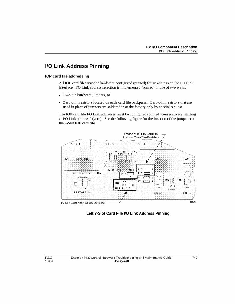
PM I/O Component DescriptionI/O Link Address Pinning
R210 Experion PKS Control Hardware Troubleshooting and Maintenance Guide 74710/04 Honeywell
I/O Link Address Pinning
IOP card file addressing
All IOP card files must be hardware configured (pinned) for an address on the I/O LinkInterface. I/O Link address selection is implemented (pinned) in one of two ways:
• Two-pin hardware jumpers, or
• Zero-ohm resistors located on each card file backpanel. Zero-ohm resistors that areused in place of jumpers are soldered in at the factory only by special request
The IOP card file I/O Link addresses must be configured (pinned) consecutively, startingat I/O Link address 0 (zero). See the following figure for the location of the jumpers onthe 7-Slot IOP card file.
Left 7-Slot Card File I/O Link Address Pinning
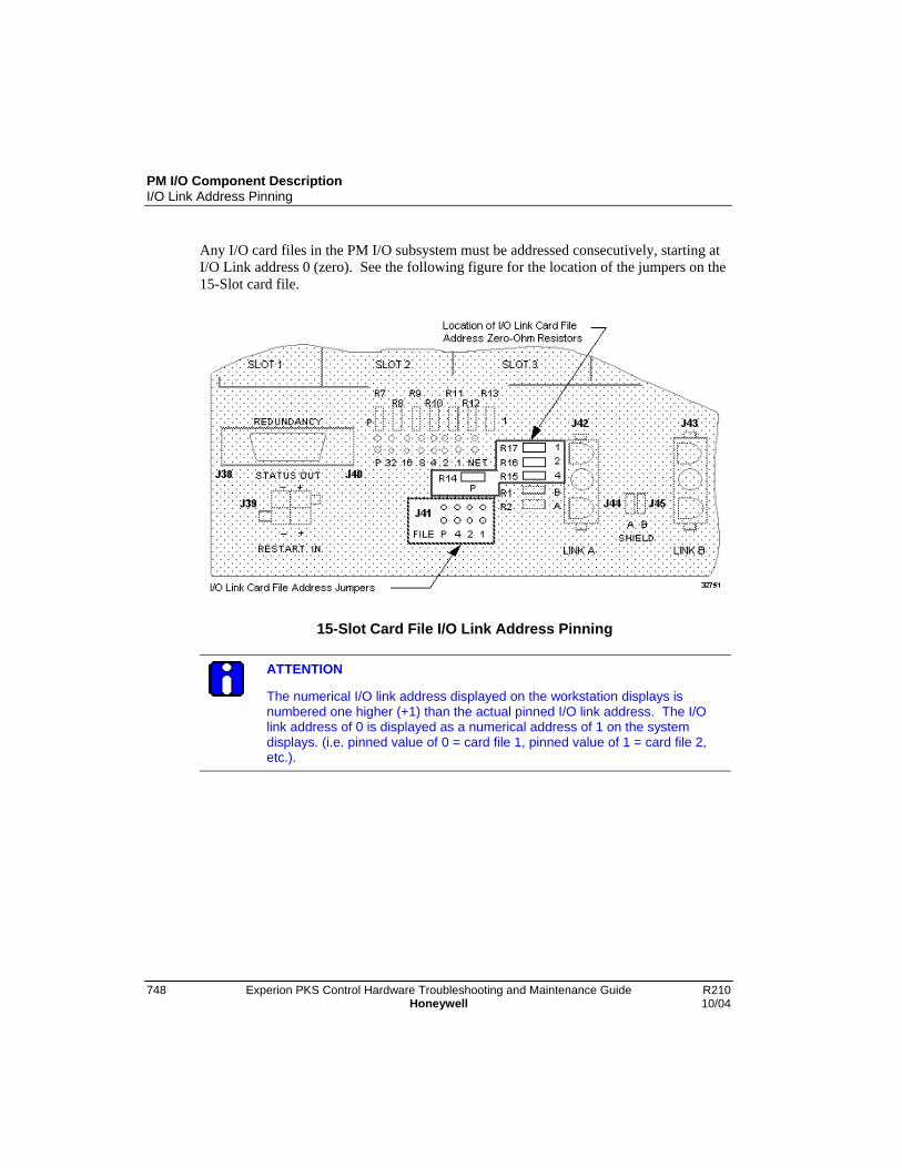
PM I/O Component DescriptionI/O Link Address Pinning
748 Experion PKS Control Hardware Troubleshooting and Maintenance Guide R210Honeywell 10/04
Any I/O card files in the PM I/O subsystem must be addressed consecutively, starting atI/O Link address 0 (zero). See the following figure for the location of the jumpers on the15-Slot card file.
15-Slot Card File I/O Link Address Pinning
ATTENTION
The numerical I/O link address displayed on the workstation displays isnumbered one higher (+1) than the actual pinned I/O link address. The I/Olink address of 0 is displayed as a numerical address of 1 on the systemdisplays. (i.e. pinned value of 0 = card file 1, pinned value of 1 = card file 2,etc.).
PM I/O Component DescriptionI/O Link Address Pinning
R210 Experion PKS Control Hardware Troubleshooting and Maintenance Guide 74910/04 Honeywell
One method only
Use only one of the two methods to set the I/O link interface address for the IOP cardfiles. Either remove all jumpers and use the zero-ohm resistors to set the address, or clipout the zero-ohm resistors and use the jumpers. The jumper method (without theresistors) is the most common method.
ATTENTION
Whichever method you use, please note that there are four address positionslabeled 1, 2, 4 and P. The "P" position is for parity. It is used so that all I/Olink addresses are set using an odd number of jumpers, (or resistors). Seeexamples below.
Jumper method example
I/O Link address configuration using plug jumpers is demonstrated with the followingexample. Refer to the following figure to locate the 7-slot card file pinning area (J26) forthe following procedure.
Step Action
1 Assume an IOP card file is to be configured for an I/O Link hardware addressof 4.(The workstation will display this card file’s I/O Link address as 5.)
2 Take diagonal cutters and remove all the zero-ohm resistors.
3 Install a plug jumper to bridge both pins at position 4.
NOTE: Because this single jumper constitutes an odd number of jumpers,remove the P (parity) plug jumper as well as all others.
Even though the J-number (J26 in this case) differs between the 7-Slot and 15-Slot cardfiles, the method of pinning the card file address remains the same.

PM I/O Component DescriptionI/O Link Address Pinning
750 Experion PKS Control Hardware Troubleshooting and Maintenance Guide R210Honeywell 10/04
Left 7-Slot Card File I/O Link Address Pinning with Plug Jumpers
Zero-ohm resistor jumper pinning example
I/O Link address configuration using zero-ohm resistor jumpers is demonstrated with thefollowing example. Refer to the following figure to locate the 7-slot card file resistorjumper area for the following procedure.
Step Action
1 Assume an I/O card file is to be configured for an I/O Link hardware addressof 3. (The workstation will display this card file’s address as 4.)
2 Remove all the plug jumpers and set them aside.
3 Leave the zero-ohm resistors at positions 1 and 2 (1 + 2 = 3), and leave the P(parity) zero-ohm resistor because an odd number of jumpers is required.
(A logic one is created by leaving the zero-ohm resistor in place and a zero iscreated by removing the zero-ohm resistor. )
4 Remove all other zero-ohm resistors with diagonal cutters.
Even though the jack number (J26 in this case) differs between the 7 and 15-Slot cardfiles, the method of pinning the card file address remains the same.

PM I/O Component DescriptionI/O Link Address Pinning
R210 Experion PKS Control Hardware Troubleshooting and Maintenance Guide 75110/04 Honeywell
Left 7-Slot Card File I/O Link Address Pinning with Zero-Ohm Resistors
If a zero-ohm resistor jumper is incorrectly removed, do not attemptto correct the problem by resoldering the jumper. The backpanelcan be easily damaged. Instead, remove all the zero-ohm resistorjumpers and configure the card file’s I/O Link Interface address withthe plug jumpers

PM I/O Component DescriptionI/O Link Address Pinning
752 Experion PKS Control Hardware Troubleshooting and Maintenance Guide R210Honeywell 10/04

R210 Experion PKS Control Hardware Troubleshooting and Maintenance Guide 75310/04 Honeywell
Removal and Replacement of PM I/O Components
ESD Guidelines
ESD HAZARD
It is extremely important that you wear a properly connected ElectrostaticDischarge (ESD) wriststrap while removing, handling, and installing theseProcess Manager I/O components. Slip the strap on your wrist like awristwatch and connect its clip to the ground bus located inside the left frontside of the cabinet. There is no danger of personnel receiving shocks fromwearing an approved wrist strap. Be sure to place the component in a static-safe carrying pouch, if appropriate, immediately after its removal.
Static discharge effects
When inserting an IOP card into a card file and following normal ESD procedures, othercards in the card file can go OFFNET because of electrostatic discharge. It does notresult in damage to any of the components on the card when an ESD wriststrap is worn,but does affect subsystem integrity. A procedure has been developed to discharge thecard using a 10 megaohms Static Discharge Probe.
ESD kitHoneywell has available an ESD kit, part number 30185H, that contains the followingcomponents.
• 10 megaohm static discharge probe
• Static discharge wriststrap (AESOPS Inc. Model 31531)
• Static discharge cord, 15 feet (AESOPS Inc. Model 30204)
• Static discharge cord, 6 feet (AESOPS Inc. Model 30205)
• Antistatic work surface with bag
Building a static discharge probe
A static discharge probe can be built by placing a 10 megaohm resistor in series with anyavailable probe or clip lead.
Removal and Replacement of PM I/O ComponentsESD Guidelines
754 Experion PKS Control Hardware Troubleshooting and Maintenance Guide R210Honeywell 10/04
ESD prevention rules
When installing a firmware upgrade, or replacing or adding a card, adhere to thefollowing rules to prevent ESD from affecting the IOP cards.
• Ground the antistatic work surface to the card file chassis.
• Ground the wriststrap that is to be worn when removing or inserting card to the cardfile chassis.
• Ground the wriststrap that is to be worn when upgrading card firmware to theantistatic work surface.
• When removing or inserting a card, handle only the card frame. Do not touch thecircuit board or the components
• The 10 megaohm static discharge probe must be grounded to the card file chassis.
• When inserting a card, insert the card 3/4 of the way into the slot and then dischargethe card with the 10 megaohm static discharge probe by touching the lower lead of theupper LED, or if there is a daughter board, touch the minus/lower lead of the bypasscapacitor labeled C1 or C2.

Removal and Replacement of PM I/O ComponentsIOP Cards
R210 Experion PKS Control Hardware Troubleshooting and Maintenance Guide 75510/04 Honeywell
IOP Cards
Cycling power or removing nonredundant Analog or Digital OutputIOPs results in their outputs going to the nonpowered stateregardless of the FAILOPT selection configured. Follow the Analogor Digital Standby Manual device instructions in this section.
Replacing IOP cardsUse the following procedure to remove and replace an IOP card.
Step Action
1 Connect your ESD wriststrap to the cabinet’s ground bar.
2 Before removing an analog or digital output IOP from a card file, systemoperational requirements may require that a Standby Manual device beconnected to the FTA to control operations while the IOP is removed.
3 Any IOP card can be removed by simultaneously pulling on the upper andlower extractor levers. When the upper extractor is first moved, power isdisconnected from the card. Further operation of both extractors moves thecard away from its backpanel connector.
4 After the card is free from the connector, carefully slide it out on the card railsand into your hands. Immediately place the card in a static-safe pouch fortransport.
5 With your ESD wriststrap still attached, remove the replacement card from itspouch.
6 Carefully slide the card onto the card rails, checking to be sure that the cardis inserted in both rails.
7 Slide the card into the card file until it has made contact with the backpanelconnectors. Then firmly press on the front of the card with the heel of yourhand. Do not use excessive force! If the card doesn't slip easily into itsconnectors, remove the card and locate the source of the obstruction. Checkfor bent contacts at the backpanel connectors.
Removal and Replacement of PM I/O ComponentsStandby Manual Devices
756 Experion PKS Control Hardware Troubleshooting and Maintenance Guide R210Honeywell 10/04
Standby Manual Devices
About devices
A Standby Manual device provides the capability to maintain output signals from anAnalog Output or 24 Vdc Digital Output FTA while its nonredundant IOP is replaced.An Analog Output IOP to FTA cable can be replaced if an external power source isconnected directly to the Standby Manual device, since the cable is the FTA’s normal 24Vdc source. The IOP switching module on the Analog Output FTA can also be replaced.
No external power source option
The Digital Output Standby Manual device does not have an external power sourceoption.
Standby Manual device connections
The connection of the Analog Output Standby Manual device and the Digital OutputStandby Manual device to the FTA differs. The Analog Output Standby Manual deviceconnects by cable to a unique connector on the FTA that is labeled STANDBYMANUAL. The Digital Output Standby Manual device connects to one of the two IOPinterface connectors as shown in the following figure for a model MU-TDON12 24 VdcDigital Output FTA.
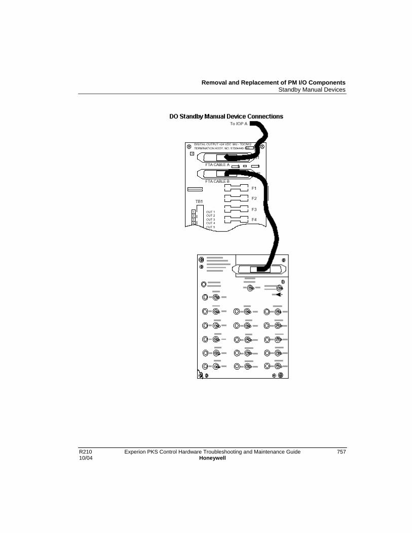
Removal and Replacement of PM I/O ComponentsStandby Manual Devices
R210 Experion PKS Control Hardware Troubleshooting and Maintenance Guide 75710/04 Honeywell

Removal and Replacement of PM I/O ComponentsStandby Manual Devices
758 Experion PKS Control Hardware Troubleshooting and Maintenance Guide R210Honeywell 10/04
Device interchangeability
There is an interchangeability problem with the Digital Output Standby Manual devices.The software Release 300, or later, model of the Digital Output Standby Manual deviceis not compatible with a Release 230, or earlier Digital Output FTA, nor is the Release230, or earlier, Digital Output Standby Manual device compatible with a softwareRelease 300, or later, FTA. Software Release 300, or later, devices are identified byhaving phone-type cable connectors, while software Release 230, or earlier, devices haveDIN-type cable connectors.
DIN to phone connector adaptor cable
A DIN to phone connector adaptor cable, Honeywell part number 51201561-xxx, wherethe suffix “xxx” is the length of the cable in meters, can be used to interconnect anincompatible Digital Output Standby Manual device to an FTA, provided the circuitboard inside the Digital Output Standby Manual device is the proper revision as follows.
• Digital Standby Manual device with phone connectorPWB 51304451-100, Revision B
• Digital Standby Manual device with DIN connectorPWB 51304076-100, Revision C
Board revision level
The 24 Vdc required by the Digital Output Standby Manual device will be missing if thedevice’s circuit board is not at the listed revision level. The R230 and R300 AnalogOutput Standby Manual devices do not have the same problem.

Removal and Replacement of PM I/O ComponentsAO Standby Manual Device Operation
R210 Experion PKS Control Hardware Troubleshooting and Maintenance Guide 75910/04 Honeywell
AO Standby Manual Device OperationAbout AOSM device
There are two models of the Analog Output Standby Manual (AOSM) device. Bothmodels provide the same primary function, which is to control the loads connected to anAnalog Output FTA while its associated Analog Output IOP can be removed fromservice and replaced. The Analog Output Standby Manual device connects to the AnalogOutput FTA and provides control of any or all eight of the outputs that are normallycontrolled by the IOP.
Two models
The original Analog Output Standby Manual device model is not as convenient to use asthe newer compact Analog Output Standby Manual device model which also offers morefeatures. A description and the use of both models is discussed in the information thatfollows.
Original Analog Output Standby Manual device
The original model MU-SMAC01/MU-SMAC02 Analog Output Standby Manual(AOSM) device, as shown in the following figure, monitors the outputs of an AnalogOutput (AO) IOP by displaying its output values on meters as a percentage of the range.The following figure illustrates one of the two Analog Output Standby Manual deviceassemblies that comprise the Analog Output Standby Manual device. When you pressone of the BAL switches on the Analog Output Standby Manual device, thecorresponding meter indicates the IOP’s output value. Using the VALVE knob, youadjust the Analog Output Standby Manual device's output to match the output of the IOP.Then, you switch control of the FTA output to the Standby Manual device by moving themode switch to the MAN position.
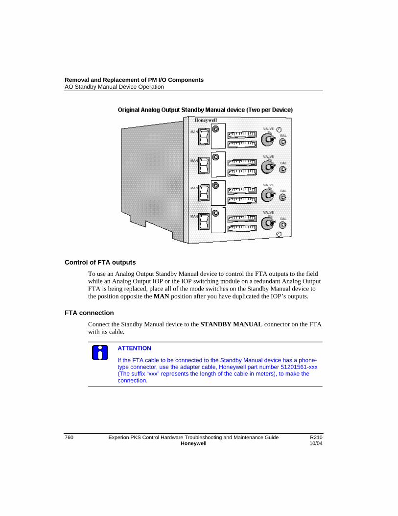
Removal and Replacement of PM I/O ComponentsAO Standby Manual Device Operation
760 Experion PKS Control Hardware Troubleshooting and Maintenance Guide R210Honeywell 10/04
Control of FTA outputs
To use an Analog Output Standby Manual device to control the FTA outputs to the fieldwhile an Analog Output IOP or the IOP switching module on a redundant Analog OutputFTA is being replaced, place all of the mode switches on the Standby Manual device tothe position opposite the MAN position after you have duplicated the IOP’s outputs.
FTA connection
Connect the Standby Manual device to the STANDBY MANUAL connector on the FTAwith its cable.
ATTENTION
If the FTA cable to be connected to the Standby Manual device has a phone-type connector, use the adapter cable, Honeywell part number 51201561-xxx(The suffix “xxx” represents the length of the cable in meters), to make theconnection.

Removal and Replacement of PM I/O ComponentsAO Standby Manual Device Operation
R210 Experion PKS Control Hardware Troubleshooting and Maintenance Guide 76110/04 Honeywell
Standby Manual device control procedure
Use the following procedure as a typical guide to provide Standby Manual device controlof the FTA field devices.
Step Action
1 In Monitor tab of Control Builder, click Controller->Upload and click Continueto upload IOP data from the Controller to the Monitor database.
2 Click Controller->Update to Project and click Continue to update IOP data inProject.
3 For the first output, press the BAL switch and note the IOP’s output value.
4 Release the BAL switch and adjust the VALVE knob to make the output ofthe AnalogOutput Standby Manual device equal to the output of the IOP.
5 Place the mode switch for this output in the MAN position.
6 Repeat Steps 3 through 5 for all remaining outputs from the IOP.
7 Remove and replace the IOP or switching module, as appropriate, andproceed to the Normal IOP Control procedure.
Normal IOP control procedureUse the following procedure to return to normal IOP control of the FTA field devices.
Step Action
1 In Project tab of Control Builder, click applicable IOP icon and clickController->Load to call up the Load Dialog. Click OK to reload the IOP datafrom Project.
2 In Monitor tab, open the Control Module containing the strategy that iscontrolling the first output channel for the IOP. Put this point in Manual mode.
3 Manually set the output of the first IOP channel to match that of the AnalogOutput Standby Manual device.
4 On the Analog Output Standby Manual device, change the mode switch forthis output to the position opposite the MAN position.
5 Return the point controlling the output to its Normal mode and close theControl Module.
6 Repeat Steps 2 through 5 for all remaining outputs from the IOP.

Removal and Replacement of PM I/O ComponentsAO Standby Manual Device Operation
762 Experion PKS Control Hardware Troubleshooting and Maintenance Guide R210Honeywell 10/04
Step Action
7 Disconnect the Analog Output Standby Manual device cable from theSTANDBY MANUAL connector on the FTA, if desired.
Compact Analog Output Standby Manual device
The compact Analog Output Standby Manual (AOSM) device display panel, as shown inthe following figure, monitors the outputs of an Analog Output (AO) IOP as well as theAOSM itself, presenting their output values on the display panel as a percentage of therange. It can be ordered by Honeywell part number 51401926-100.
Removal and Replacement of PM I/O ComponentsAO Standby Manual Device Operation
R210 Experion PKS Control Hardware Troubleshooting and Maintenance Guide 76310/04 Honeywell
Compact device featuresThe Analog Output Standby Manual device has the following features.
• The Analog Output Standby Manual device will accept the standard IOP to FTAcables with either DIN or phone type connectors.
• The Analog Output Standby Manual device can be powered by any of two methods.
− The IOP card file backpanel through its connection to the STANDBY MANUALconnector on the FTA.
− By applying 110 or 220 Vac to connector at the side of the AOSM. The universalpower supply in the AOSM will accept 100 to 240 Vac, 50/60 Hz.
• The panel display shows the 4-20 milliamp current levels in a 0% to 100% scale for alleight IOP outputs as well as the level of all eight AOSM outputs.
• The toggle switches are a “tamper-proof” style that require the operator to lift up onthe bat handle before changing the switch position.
• The compact AOSM’s output current and the its OUTPUT SOURCE SELECTswitches are disabled when the device is first connected to the FTA, the STANDBYENABLE indicator is extinguished, or the cable to the FTA is disconnected.
• When the AOSM is enabled by depressing the STANDBY ENABLE switch, theSTANDBY ENABLE indicator is illuminated and the OUTPUT SOURCESELECT switch settings are active.
• The balancing of the AOSM output values to equal the IOP output values is performedautomatically, either continuously, or by single snapshot action. Balancing in the otherdirection, IOP to AOSM, is an operator function.
• A DIR/REV switch for each channel flips the display and reverses the INC/DECaction relative to the actual current level. In the DIR position, 4 mA equals 0% and 20mA equals 100%. The INC position of the INC/DEC switch will increase current andthe DEC position will decrease current. With the DIR/REV switch in the REVposition, 20 mA equals 0% and 4 mA equals 100%. The INC position of theINC/DEC switch will decrease current and the DEC position will increase current.
Removal and Replacement of PM I/O ComponentsAO Standby Manual Device Operation
764 Experion PKS Control Hardware Troubleshooting and Maintenance Guide R210Honeywell 10/04
Compact ASOM device control procedure
Use the procedure in the following table to provide Standby Manual device control of theFTA field devices.
Step Action
1 In Monitor tab of Control Builder, click Controller->Upload and click Continueto upload IOP data from the Controller to the Monitor database.
2 Click Controller->Update to Project and click Continue to update IOP data inProject.
3 Be sure all the OUTPUT SOURCE SELECT switches are in the PM position.
4 Place the DIR/REV switches in the correct position for all eight channels.
5 Connect a standard IOP to FTA cable between the STANDBY MANUALconnector on the FTA and the AOSM.
6 Verify that all OUTPUT SOURCE SELECT switches are in the PM position.
7 The BALANCE switch has three positions, left (CONT), center (inactive), andright (PUSH TO BALANCE). Select the left or right position.
CONT Position
In the CONTinuous (left) position, the switch remains toggled and all thechannels with their OUTPUT SOURCE SELECT switch in the PM position willautomatically have their Standby Manual device output level continuously setequal to the IOP level. Manual INCrement and DECrement control for achannel is not possible when a channel is in the PM position while theBALANCE switch is in the CONT position.
PM Position
In the PUSH TO BALANCE (right) position, the position is momentary and allchannels with their OUTPUT SOURCE SELECT switch in the PM position willautomatically have their Standby Manual device output level set equal to theIOP output level. However, this balance method is a single event and theswitch returns to the center position when it is released. Any subsequentchange in the IOP’s output level will not be transferred to the StandbyManual, but the INCrement and DECrement control for a channel can alterthe Standby Manual device’s current level.
8 The STANDBY ENABLE switch can now be pressed. The green LEDilluminates to indicate that the FTA is now ready for control by the StandbyManual device.

Removal and Replacement of PM I/O ComponentsAO Standby Manual Device Operation
R210 Experion PKS Control Hardware Troubleshooting and Maintenance Guide 76510/04 Honeywell
Step Action
9 Placing any or all of the OUTPUT SOURCE SELECT switches in the MANualposition will automatically place all eight IOP channels in the Standby Manualmode.
10 When all eight OUTPUT SOURCE SELECT switches are in their MANualposition, the Analog Output IOP can be placed in the Idle state and removed.
11 Replace the IOP and proceed to the Return to normal IOP control procedure.
Return to Normal IOP control procedure
Use the procedure in the following table to return to normal IOP control of the FTA fielddevices.
Step Action
1 In Project tab of Control Builder, click applicable IOP icon and clickController->Load to call up the Load Dialog. Click OK to reload the IOP datafrom Project.
2 In Monitor tab, open the Control Module containing the strategy that iscontrolling the first output channel for the IOP. Put this point in Manual mode.
3 Manually set the output of the first IOP channel to match that of the AnalogOutput Standby Manual device.
4 When the output level for first channel matches the output level of the AnalogOutput Standby Manual device, place the OUTPUT SOURCE SELECTswitch for the channel in the PM position. The IOP will now be controlling thechannel.
5 Return the point controlling the output to its Normal mode and close theControl Module.
6 Repeat Steps 2 through 5 for IOP channels 2 through 8.
7 Disconnect the Analog Output Standby Manual device cable from theSTANDBY MANUAL connector on the FTA, if desired.

Removal and Replacement of PM I/O ComponentsDO Standby Manual Device Operation
766 Experion PKS Control Hardware Troubleshooting and Maintenance Guide R210Honeywell 10/04
DO Standby Manual Device Operation
About the DOSM device
The primary function of the model MU-SMDC02 or model MU-SMDX02 Digital OutputStandby Manual (DOSM) device is to control Digital Output FTAs while the associatedDigital Output IOP card is serviced. Except in the case of the +24 Vdc nonisolated FTAwhich has no relays, the FTA’s relays are controlled, not their loads.
Secondary function
A secondary function of the Digital Output Standby Manual device is to indicate the stateof each IOP output (LED on = output on). The LEDs indicate the output state of the IOPas soon as the connection is made.
Mounting locations
The model MU-SMDX02 Digital Output Standby Manual device can be mounted in anHPM cabinet on an FTA Mounting Channel. The model MU-SMDC02 Digital OutputStandby Manual device is mounted in a carrying case for portable applications.

Removal and Replacement of PM I/O ComponentsDO Standby Manual Device Operation
R210 Experion PKS Control Hardware Troubleshooting and Maintenance Guide 76710/04 Honeywell
DOSM connection
Connection of the Digital Output Standby Manual device to the FTA Standby connectoris made with a standard IOP to FTA cable. A 3-meter cable is included with the modelMU-SMDC02 Digital Output Standby Manual device that is shown in the followingfigure.
Output control switches disablement
The Digital Output Standby Manual device’s output control switches are disabled whenthe DOSM is first connected to the FTA, or whenever the ENABLE STANDBY switchon the DOSM is in the OFF position.
Removal and Replacement of PM I/O ComponentsDO Standby Manual Device Operation
768 Experion PKS Control Hardware Troubleshooting and Maintenance Guide R210Honeywell 10/04
Switch activation
When the ENABLE STANDBY switch is in the ON position, momentary operation ofthe ACTIVATE STANDBY switch latches the manual mode of the Digital OutputStandby Manual device and activates the 16 output switches to control the FTA asdiscussed below.
ATTENTION
The IOP to FTA cable, from the card file backpanel to the FTA, must beconnected to carry the +24 Vdc and the common from the IOP backpanel tothe FTA and the Digital Output Standby Manual device. Also, the DigitalOutput Standby Manual device cannot be used with the 24 Vdc nonisolatedDigital Output FTA if the FTA load voltage for any output is other than +24Vdc.
DOSM device control procedureUse the Controller menu commands Upload and Update to Project for the IOP(s) inMonitor tab of Control Builder, if desired, and then use the following procedure toprovide Standby Manual device control of the FTA field devices.
Step Action
1 Place ENABLE STANDBY switch on the Digital Output Standby Manualdevice in the OFF position.
2 Connect the Digital Output Standby Manual device cable to the FTA CABLEB connector, J2, on the Digital Output FTA.
3 When the Digital Output Standby Manual device is connected to theconnector on the Digital Output FTA, all "on" IOP outputs light theircorresponding indicator on the Digital Output Standby Manual device. Thefollowing figure shows a model MU-SMDX02 Digital Output Standby Manualdevice panel. If you only want to display outputs, stop at this Step.

Removal and Replacement of PM I/O ComponentsDO Standby Manual Device Operation
R210 Experion PKS Control Hardware Troubleshooting and Maintenance Guide 76910/04 Honeywell
Step Action
4 If you want to use the Digital Output Standby Manual device to hold thecurrent FTA output states while servicing the associated Digital Output IOP,set the 16 output switches equal to the output state that is displayed by theLEDs on the Digital Output Standby Manual device and perform Steps 5through 7 below. You can also set any of the 16 output switches to analternate state, if desired.
5 Place the ENABLE STANDBY switch on the Digital Output Standby Manualdevice in the ON position.
6 Toggle the momentary ACTIVE STANDBY switch on the Digital OutputStandbyManual device. The STANDBY ACTIVATED LED should illuminate.This allows the Digital Output Standby Manual device’s switch settings tocontrol the Digital Output FTA and also send a status signal to the IOP toindicate that the connected Digital Output Standby Manual device is armedand possibly controlling FTA outputs.
Removal and Replacement of PM I/O ComponentsDO Standby Manual Device Operation
770 Experion PKS Control Hardware Troubleshooting and Maintenance Guide R210Honeywell 10/04
Step Action
7 While the Digital Output Standby Manual device is controlling outputs, theIOP can be placed in the idle mode or removed/replaced for servicing, andthe FTA outputs will be held by the Digital Output Standby Manual device.After servicing the IOP, proceed to the DOSM to normal IOP controlprocedure to restart the IOP.
DOSM to normal IOP control procedure
After using the Digital Output Standby Manual device to maintain FTA digital outputstates while servicing the associated Digital Output IOP, use the following procedure toreturn FTA output control to the IOP
Step Action
1 In Project tab of Control Builder, click applicable IOP icon and clickController->Load to call up the Load Dialog. Click OK to reload the IOP datafrom Project.
2 In Monitor tab, open the Control Module containing the strategy that iscontrolling the first status output (SO) channel for the IOP.
3 Manually set the output of the first SO to match that of the Digital OutputStandby Manual device.
4 Repeat Steps 2 and 3 for the remaining IOP channels.
5 Set the ENABLE STANDBY switch on the Digital Output Standby Manualdevice to the OFF position. The STANDBY ACTIVATED LED should be “off,”indicating that the Digital Output Standby Manual device is no longercontrolling the FTA digital outputs. Control has been returned exclusively tothe IOP.
6 Remove the Digital Output Standby Manual device connection to the FTA, ifdesired.
ATTENTION
When a digital output point indicates Standby Manual mode (STDBYMAN) onan operating display, such as Group or Detail, the output cannot be changedusing that display. To set the point output to match the Digital Output StandbyManual device setting, the output point must be set through the applicablecontrol drawing in Control Builder.

Removal and Replacement of PM I/O ComponentsIOP Card Case Replacement
R210 Experion PKS Control Hardware Troubleshooting and Maintenance Guide 77110/04 Honeywell
IOP Card Case Replacement
Handling and installing IOP components
ESD HAZARD
It is extremely important that you wear a properly connected ElectrostaticDischarge (ESD) wrist strap while removing, handling, and installing theseIOP components.
Replacing plastic caseUse the following procedure to replace the plastic case on a card assembly.
Step Action
1 Remove the card assembly from the card file. Place the card on a static freework surface.
2 Remove the two screws at the corners near the connector edge of the cardas illustrated in the following figure.
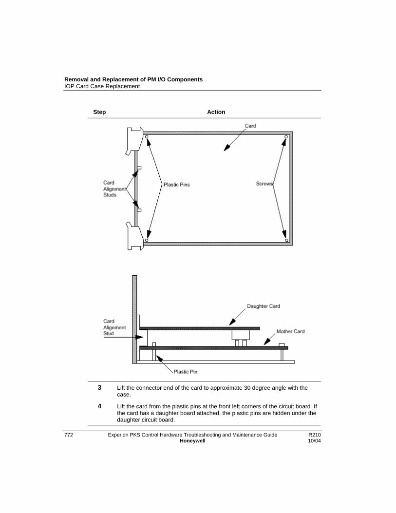
Removal and Replacement of PM I/O ComponentsIOP Card Case Replacement
772 Experion PKS Control Hardware Troubleshooting and Maintenance Guide R210Honeywell 10/04
Step Action
3 Lift the connector end of the card to approximate 30 degree angle with thecase.
4 Lift the card from the plastic pins at the front left corners of the circuit board. Ifthe card has a daughter board attached, the plastic pins are hidden under thedaughter circuit board.
Removal and Replacement of PM I/O ComponentsIOP Card Case Replacement
R210 Experion PKS Control Hardware Troubleshooting and Maintenance Guide 77310/04 Honeywell
Step Action
5 To insert the card in the new case, place the front of the card on the plasticpins while holding the card at approximately a 30 degree angle. If a daughterboard is attached, the two alignment studs at the front edge of the case mustfit between the two circuit boards. See the figure above after Step 2.
6 Lay the card flat on the work surface and replace the two screws removed inStep 2.
7 Check the alignment of the LEDs with the openings in the front of the plasticcase for visibility.
8 Reinstall the card in the card file.

Removal and Replacement of PM I/O ComponentsIOP to FTA Cable Replacement
774 Experion PKS Control Hardware Troubleshooting and Maintenance Guide R210Honeywell 10/04
IOP to FTA Cable Replacement
Nonredundant IOP cable replacement
All outputs or inputs carried by the IOP to FTA cable, as well as 24 Vdc from the IOPthat powers the FTA, will be disconnected when the cable is removed. The use of anAnalog Output or Digital Output Standby Manual device may be appropriate to maintainthe present outputs of an output type FTA. See one of these previous sections for moreinformation.
• AO Standby Manual Device Operation
• DO Standby Manual Device Operation
Redundant IOP cable replacement
Before removing an IOP to FTA cable from a redundant IOP configuration, be sure thatthe FTA cable to be removed is not controlling analog output field terminals on the FTAor providing inputs. When the green DS1 LED on an AO redundancy FTA is illuminated,the “B” FTA cable can be removed, since the “A” FTA cable is controlling the FTAoutput field terminals. When the green DS1 LED on an AO redundancy FTA is notilluminated, the “A” FTA cable can be removed, since the “B” FTA cable is controllingthe FTA output field terminals. The IOP forms in the Monitor tab can also be used todetermine whether the “A” or “B” FTA cable is controlling the FTA output fieldterminals.
For critical analog outputs, it is recommended that the “A” AO IOP be removed beforethe “A” FTA cable is removed. It is also recommended that the “B” AO IOP be removedbefore the “B” FTA cable is removed.
When removing FTA cables from High Level Analog Input (HLAI) IOPs, use the IOPconfiguration forms in Monitor mode to determine whether or not the cable beingremoved is being used to provide subsystem inputs.
Removal and Replacement of PM I/O ComponentsIOP to FTA Cable Replacement
R210 Experion PKS Control Hardware Troubleshooting and Maintenance Guide 77510/04 Honeywell
FTA ReplacementUse the following procedure to replace an FTA.
ATTENTION
Remove power from the FTA by unplugging the IOP to FTA cable beforedisconnecting the process wiring.
Step Action
1 Unplug the cable(s) from the associated IOP card connector to the FTA at theFTA. Remove the field power serving the FTA to be replaced. Unplug thefield wiring terminal-strip from the FTA. It is not necessary to unscrew thefield wiring if compression terminals are used.
2 Remove the screws that hold the FTA to the mounting channel. Carefullyremove the FTA.
3 Compare the replacement FTA with the removed FTA. Be sure any 250 ohmor zero-ohm resistors that have been clipped on the removed FTA are alsoclipped on the replacement FTA. Be sure all fuses are in place and jumpersare properly positioned.
4 Install the replacement FTA with the screws that were removed in step 2.Rotate them counterclockwise until they fall into the original threads, thentighten them clockwise. Reconnect the field wiring terminal connector andthe cable from the associated IOP card(s).

Removal and Replacement of PM I/O ComponentsFTA Module and Relay Replacement
776 Experion PKS Control Hardware Troubleshooting and Maintenance Guide R210Honeywell 10/04
FTA Module and Relay Replacement
Replacing FTA Module or Relay
Modules and relays plug into the FTA circuit boards and are held in place by a retainingscrew(s). Usethe following procedure to replace a module or relay.
SHOCK HAZARD
Risk of electric shock exists, whem removing and replacing a FTA module orrelay.
Step Action
1 Remove the screw(s) holding the module or relay to the circuit board andthen firmly lift it straight away until it is free.
2 Align the replacement module or relay with the holes and connector on theFTA circuit board before inserting it. Replace the retaining screw(s).
LLAI Module replacement
The LLAI plug-in module can be replaced while power is applied to the FTA. Afterreplacement, power initialize the LLAI IOP. The initialization will initiate a backgrounddiagnostics. Allow at least two (2) minutes for it to complete before analyzing the results.
AO redundancy switching module replacement
Before removing the Analog Output (AO) Redundancy Switching Module from an AORedundancy FTA for testing or replacement, be sure that the associated “A” AO IOP iscontrolling the FTA outputs. When the green DS1 LED on the FTA is illuminated, theassociated “A” AO IOP is controlling the FTA’s output. The HPM Status display at theUniversal Station also can also be used to determine if the “A” AO IOP is controlling theFTA output.
For critical analog outputs, it is recommended that the “B” AO IOP be removed, or anAnalog Output Standby Manual device be connected before removing the Analog OutputRedundancy Switching Module.

Removal and Replacement of PM I/O ComponentsCard File Replacement
R210 Experion PKS Control Hardware Troubleshooting and Maintenance Guide 77710/04 Honeywell
Galvanic isolation module replacement
If the field device, controlled by a Galvanic Isolation Module that must be replaced, is anoutput device, be sure the loss of control is acceptable. Also, when the environment isDivision 2, be sure the atmosphere is nonhazardous. The module can be removed andreplaced while power is applied to the FTA. Remove the module’s pluggable fieldconnector. Loosen the screws that retain the module. Lift the module from its connectoron the FTA and replace it. Reinstall the pluggable field connector.

Removal and Replacement of PM I/O ComponentsCard File Replacement
778 Experion PKS Control Hardware Troubleshooting and Maintenance Guide R210Honeywell 10/04
Card File Replacement
Replacing card fileUse the following procedure to replace a card file.
Step Action
1 Disconnect all cables attached to the card file.
2 Remove the side plates connecting the card file to the card file above and/orbelow by first removing the two screws at the inside of the panel.
3 Loosen, but do not remove, the four screws holding the card file to itssupports.
4 Grasp the card file firmly and lift it about 1 cm (1/2 inch) to release the cardfile into your hands.
5 Install the replacement card file in a reverse manner, making sure it isengaged by all four mounting screws. Tighten the screws when the card file isin place. Reconnect the cables that were disconnected in Step 1.

Removal and Replacement of PM I/O ComponentsPower System
R210 Experion PKS Control Hardware Troubleshooting and Maintenance Guide 77910/04 Honeywell
Power System
About the power system
The sections that follow describe the removal and replacement of major assemblies in thePowerSystem.
If all options are installed, most of the major assemblies in the Power System can beremoved and replaced while the HPM remains in operation because of Power SupplyModule redundancy and battery backup power. Observe all precautions mentioned in thistext when replacing the Power System components.
CAUTION
Batteries may contain toxic materials that are not biodegradable. Batteriesshould be disposed of safely in accordance with local laws and regulations.

Removal and Replacement of PM I/O ComponentsCMOS Battery Replacement
780 Experion PKS Control Hardware Troubleshooting and Maintenance Guide R210Honeywell 10/04
CMOS Battery Replacement
NiCad batteries
The three NiCad batteries that are installed in the Standard Power System to providestandby power for the CMOS memory have a tendency to age over a period of time.Aging occurs even if the batteries have been regularly recharged throughout theirlifetime. For this reason, the NiCad batteries should be replaced after every two years ofoperation.
Replacing NiCad batteriesUse the following procedure to replace the NICad batteries.
Step Action
1 Remove the old batteries from the battery holder and replace them with freshones. It is not necessary to remove power from the batteries while they arebeing replaced.
2 Observe and match the polarity marked on the case of each battery and theholder. After all the batteries are in place, rotate each one slightly with yourfinger to assure it makes good contact with the holder.
Alkaline batteriesThe alkaline batteries that are installed in the AC Only Power System are notrechargeable and, therefore, must be replaced more often. A six month replacement cycleis suggested, unless an equipment power failure has occurred for a prolonged period.Then, the batteries should be replaced.
Removal and Replacement of PM I/O Components48 V Backup Battery Replacement
R210 Experion PKS Control Hardware Troubleshooting and Maintenance Guide 78110/04 Honeywell
48 V Backup Battery Replacement
Battery operational and service life
The lead acid batteries provide 20 minutes of standby power for the HPM Power Systemand have a normal stand-by service life of 4 to 5 years. However, usage and highenvironmental temperatures will reduce the service life. For this reason, environmentaltemperature, battery storage time, and battery usage should be monitored and recorded.In the absence of this attention, it is recommended the battery performance be checked ona yearly basis, or be replaced every 3 years to insure proper performance.
Battery performance
All batteries of the same capacity, rating, and specifications, do not provide equivalentperformance or reliability. For optimum system backup realization, use only Honeywellrecommended and approved batteries.
48 V Battery Pack end-of-life
The battery end-of-life is defined as the time when the battery capacity, meaning itsability to accept and hold a charge, has decayed to 60% of the original capacity. Thereare several factors that determine useful service life. The standby service life is reducedby events other than a continual 20 degrees C standby condition and are defined asfollows.
• Standby (float) service life means that the batteries are connected to a charger and onlyoccasionally discharged. Honeywell 48-volt batteries are designed to operate instandby (float) service for 4 to 5 years at 20 degrees C. The service life of a battery canbe shortened by an improper charging voltage. The charging voltage from the PowerSupplies should be checked every 6 months for the proper voltage level. See thefollowing Power Supply Module section for the recommended procedure.
• As shipped from Honeywell, the batteries are fully charged. However, if a system isstored in a nonpowered state, the batteries will self-discharge and can becomeunusable. The time required for this to happen is a function of storage temperature.

Removal and Replacement of PM I/O Components48 V Backup Battery Replacement
782 Experion PKS Control Hardware Troubleshooting and Maintenance Guide R210Honeywell 10/04
If Storage Temperature is . . . Then, Self-Discharge Time is . . .
0 degrees to 20 degrees C(32 degrees to 68 degrees F)
12 months
21 degrees to 30 degreesC(69 degrees to 86 degrees F)
9 months
31 degrees to 40 degreesC(87 degrees to 104 degrees F)
5 months
41 degrees to 50 degreesC105 degrees to 122 degrees F)
2.5 months
• Batteries should not be left in a discharged condition for extended periods of time, asthis strongly affects the ability of the battery to accept a charge thereafter. Thebatteries should be charged periodically if they are stored or in an nonpowered system.
• The IOP provides proper charging current to the batteries while the subsystem ispowered up and running. Whenever ac power is removed from the subsystem, thePower System automatically draws power from the batteries to maintain thesubsystem’s 24 Vdc power. Anytime the system is intentionally shutdown and leftnonpowered, the BATTERY switch at the front of the Power System assembly shouldbe placed in the OFF position to prevent discharge of the batteries.
• Service life is directly reduced by high ambient temperature. Heat destroys batteries.While the operating temperature range is -15 degrees C to 50 degrees C (5 degrees to122 degrees F), maximum service life will be realized when the batteries are operatedin an ambient of 20 degrees C (68 degrees F). Brief usage, that is, a few days, at highertemperatures will have no adverse effect on the service life. However, if such usage isover extended periods of time or occurs repetitively (such as a environment that is notair-conditioned), the service life will be reduced. This reduction may be as much as20% of service life (1 year) for each 10 degrees C above the reference ambient of 20degrees C (68 degrees F).
Removal and Replacement of PM I/O Components48 V Backup Battery Replacement
R210 Experion PKS Control Hardware Troubleshooting and Maintenance Guide 78310/04 Honeywell
48 V Battery Pack service life
• Service life is reduced by the number of discharges and the depth of each discharge.The batteries can provide 200 cycles at 100% depth of discharge, 550 cycles at 50%depth of discharge, 1200 cycles at 30% depth of discharge, or 2000 cycles at 10%depth of discharge. This effect is superimposed on the standby aging effect statedabove.
• With an expected 5 year life, 200 cycles would represent one power outageapproximately every 9 days, or approximately 2000 ampere-hours of 24 Vdcsubsystem backup.
Battery charge voltage check procedureUse the following procedure to verify that the output voltage to the 48 Volt Battery Packis proper.
Step Action
1 Locate the test points marked "COMMON" (-) and "BATTERY" (+) at thefront of the primary Power Supply Module and connect a dc voltmeter with anaccuracy of +/- 0.05 volts across the test points.
2 The voltage should read between 54.0 volts minimum to 55.2 volts maximumat 20 degrees C. For each degree the battery enclosure temperature deviatesfrom 20 degrees C, the following adjustments in Power Supply Module’sbattery charge output voltage are applicable.
Above 20 degrees C, the battery charge voltage limits are decreased by 72mv/deg C.
Below 20 degrees C, the battery charge voltage limits are increased by 72mv/deg C.
If the charge voltage is outside of these limits, replace the module.
ATTENTION
Step 3 and step 5 should be performed during plant shutdowns, since itrequires disconnecting the battery pack and placing the redundant PowerSupply Module’s power switch in the OFF position.
3 Disconnect the battery pack. With the voltmeter connected to the primaryPower Supply Module’s battery test points, place the redundant PowerSupply Module’s power switch in the OFF position. The voltage should not fallbelow the minimum voltage specified in Step 2. If it does, replace theredundant Power Supply Module.

Removal and Replacement of PM I/O Components48 V Backup Battery Replacement
784 Experion PKS Control Hardware Troubleshooting and Maintenance Guide R210Honeywell 10/04
Step Action
4 Place the redundant Power Supply Module’s power switch in the ON position.Move the test leads to the battery test points on the redundant Power SupplyModule and place the primary Power Supply Module’s power switch in theOFF position. The voltage should not fall below the minimum voltagespecified in step 3. If it does, replace the redundant Power Supply Module.
5 Reconnect the battery pack to the Power System.
End of Battery Pack life check
The battery pack can be checked for the end of its life by using the procedure in thefollowing table.
Step Action
1 Set the BATTERY switch on the power system control panel in the OFFposition. Remove the Power System’s lower cover. You can use either ascrewdriver or a coin to remove the two screws holding it in place.
2 Release the Power System cord connector at the battery.
3 Disconnect the battery pack from the subsystem.
4 Attach two pairs of leads to the battery pack terminals. One pair of leads arefor attaching a load resistor and must be a minimum of 1.0 mm 2 (18 AWG)wire. The second pair are for attaching a voltmeter and can be a smallergauge.
5 Select a voltmeter range of 60 Vdc for monitoring the battery voltage. Attachthe voltmeter to the smaller gauge leads.
6 The battery load for the test must be 5 ohms and rated at 500 watts. Five 1-ohm, 100-watt resistors placed in series is recommended.
7 Attach the resistors to the larger test leads. Note the time of attachment.
8 The battery voltage must remain above 40 Vdc for a minimum of 20 minutes.If the battery voltage is not maintained, the battery is considered at the end ofits life and must be replaced.
9 All batteries of the same capacity, rating, and specifications, do not provideequivalent performance or reliability. For optimum battery backupperformance, use only Honeywell recommended and approved batteries.

Removal and Replacement of PM I/O Components48 V Backup Battery Replacement
R210 Experion PKS Control Hardware Troubleshooting and Maintenance Guide 78510/04 Honeywell
Battery pack removalUse the procedure in the following table to remove the battery pack.
ATTENTION
Using the following procedure will cause alarms to go off, so be sure to notifyPlant Operations in advance that alarms will occur.
Step Action
1 Set the BATTERY switch on the power system control panel to the OFFposition. Remove the Power System’s lower cover. You can use either ascrewdriver or a coin to remove the two screws holding it in place.
2 Release the Power System cord connector at the battery.
3 Remove two screws holding the front lip of the battery pack to the base of thePower system chassis.
4 Move the Power System cord out of the way so it will not be damaged whenthe battery pack is removed.
5 Slowly slide the battery pack out into your hands, but be careful, the pack isheavy. Go to the next section Battery Pack installation.
Removal and Replacement of PM I/O Components48 V Backup Battery Replacement
786 Experion PKS Control Hardware Troubleshooting and Maintenance Guide R210Honeywell 10/04
Battery Pack installationUse the procedure in the following table to install a Battery Pack.
Step Action
1 Slide the new battery pack into the Power System chassis, being careful notto damage the battery pack connector cord within the compartment.
2 Secure the pack by replacing the two screws through the front lip of the packinto the base of the chassis.
3 Connect the pack to the system by inserting the polarized battery pack pluginto the polarized connector cord in the compartment. Carefully dress thecord and connectors to prevent damage.
4 Replace the metal cover.
5 Apply power to the battery by switching the BATTERY switch to the onposition. Unless it is already in a charged condition, the battery pack mayneed to be initially charged for 16 hours before it will be capable of sustainingpower to the system.

Removal and Replacement of PM I/O ComponentsPower Supply Module Replacement
R210 Experion PKS Control Hardware Troubleshooting and Maintenance Guide 78710/04 Honeywell
Power Supply Module Replacement
Replacing power supply module
Use the procedure in the following table to replace a Power Supply Module. Theprocedure assumes that redundant Power Supply Modules are in use.
If the system is operational, do not remove both Power SupplyModules at the same time. The batteries will not power the systemunless at least one Power Supply Module is present. If one of thePower Supply Modules fails, the batteries will not be drained.
ATTENTION
• Provided the optional redundant Power Supply Module is installed, theHPM will remain in operation while replacing a Power Supply Module. Besure to notify Plant Operations that you will cause alarms during thereplacement process.
• If the primary (left side) Power Supply Module is removed from the systemor turned off, the 6 Vac is not provided to the card files because theredundant Power Supply Module does not provide 6 Vac. This can causea Soft Failure Alarm Notification for any LLAI card that is present.
Step Action
1 If the Power Supply Modules have ac present (AC In LED on), the BATTERYswitch can be placed in the OFF position. Place the BATTERY switch in theOFF position before removing the Power Supply Module. Set the recessedtoggle switch on one, and only one, Power Supply Module in the down (OFF)position. Remove two screws at the bottom of the module that hold it to theshelf of the Power System chassis.
2 Pull the Power Supply Module straight out of the housing.
3 Before installing the replacement Power Supply Module, be sure therecessed toggle switch is in the OFF position.
4 Carefully slide the replacement module into the Power System chassis. Don’tslam it into its housing. Be careful and be sure that the contacts at the back ofthe module mate properly with the fixed contacts at the back of the PowerSystem backpanel.

Removal and Replacement of PM I/O ComponentsPower Supply Module Replacement
788 Experion PKS Control Hardware Troubleshooting and Maintenance Guide R210Honeywell 10/04
Step Action
5 Secure the replacement module with two screws at the bottom of the module,then set the recessed toggle switch to the ON position. Check that the greenindicators on the supply are operating satisfactorily and that alarms can bereset.
6 Place the BATTERY switch in the ON position.

Removal and Replacement of PM I/O ComponentsCMOS Backup Assembly Replacement
R210 Experion PKS Control Hardware Troubleshooting and Maintenance Guide 78910/04 Honeywell
CMOS Backup Assembly Replacement
About CMOS Backup Assembly
Replacement of the CMOS Backup Assembly requires the removal of the redundant(right side) Power Supply Module. See the previous section for removal of the PowerSupply Module.
The following figure shows the CMOS Battery Backup assembly.
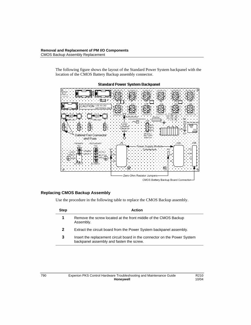
Removal and Replacement of PM I/O ComponentsCMOS Backup Assembly Replacement
790 Experion PKS Control Hardware Troubleshooting and Maintenance Guide R210Honeywell 10/04
The following figure shows the layout of the Standard Power System backpanel with thelocation of the CMOS Battery Backup assembly connector.
Replacing CMOS Backup AssemblyUse the procedure in the following table to replace the CMOS Backup assembly.
Step Action
1 Remove the screw located at the front middle of the CMOS BackupAssembly.
2 Extract the circuit board from the Power System backpanel assembly.
3 Insert the replacement circuit board in the connector on the Power Systembackpanel assembly and fasten the screw.

Removal and Replacement of PM I/O ComponentsCabinet
R210 Experion PKS Control Hardware Troubleshooting and Maintenance Guide 79110/04 Honeywell
Cabinet
Removing Markhon cabinet side panels
To remove the cabinet side panels, either for cabinet complexing or for servicerequirements, remove the two external Phillips screws, lift up on the side panelapproximately 1 to 2 inches, and pull the panel outwardly. If the panel does not release,additional lifting of the panel may be required.
Removing Rittal cabinet side panels
To remove the cabinet side panels, either for cabinet complexing or for servicerequirements, remove the six internal Phillips screws, lift up on the side panelapproximately 1 to 2 inches, and pull the panel outwardly. If the panel does not release,additional lifting of the panel may be required.
Removal and Replacement of PM I/O ComponentsI/O Link Extender Optical Coupler Module Replacement
792 Experion PKS Control Hardware Troubleshooting and Maintenance Guide R210Honeywell 10/04
I/O Link Extender Optical Coupler Module Replacement
Replacement procedures
There are two replacement procedures. They depend upon whether the Fiber OpticCoupler module is mounted in a non-CE Compliant card file or a CE Compliant card file.The CE Compliant card file requires an adapter kit because of the IOP connector groundplate.
Select the appropriate procedure from the two procedures that follow.
ATTENTION
Before removing a defective fiber Optical Coupler module, it is necessary toremove its associated I/O Link Extender card to prevent the transmission oferroneous signals on the I/O Link..
Replacing coupler in Non-CE Compliant card file
Use the procedure in the following table to replace the I/O Link Extender Coupler whenit is installed in a non-CE Compliant card file.
Step Action
1 Grasp the upper and lower extractors on the I/O Link Extender card and pullthem outward in unison. Move the card toward you until the card isdisengaged from the card file backpanel connector. It is not necessary toremove the card from the card file.
2 Disconnect the fiber optic cables from the Fiber Optic Coupler module. Besure the cables are properly labeled.
3 Using a screwdriver with a small blade, loosen the two screws that secure theFiber Optic Coupler module to the backpanel connector. Grasp the modulefirmly in your hand and pull it towards you. Place the module on an antistaticsurface or in an antistatic container.
4 Replace the defective module by reversing Step 3.
5 Reconnect the fiber optic cables to the module.
6 Reinstall the I/O Link Extender card by reversing Step 1.

Removal and Replacement of PM I/O ComponentsI/O Link Extender Optical Coupler Module Replacement
R210 Experion PKS Control Hardware Troubleshooting and Maintenance Guide 79310/04 Honeywell
Step Action
7 When you replace a Standard I/O Link Extender Fiber Optic Coupler module,you must initialize both ends of the link(s) by manually resetting the I/O LinkExtender cards using the upper card extractor on the card. When a LongDistance I/O Link Extender Fiber Optic Coupler module is replaced,reinstalling either I/O Link Extender card produces initialization at both endsof the link.
Replacing coupler in CE Compliant card fileUse the procedure in the following table to replace the Fiber Optic Coupler module whenthe coupler is installed in a CE Compliant card file.
Step Action
1 Grasp the upper and lower extractors on the I/O Link Extender card and pullthem outward in unison. Move the card toward you until the card isdisengaged from the card file backpanel connector. It is not necessary toremove the card from the card file.
2 Disconnect the fiber optic cables from the Fiber Optic Coupler module. Besure the cables are properly labeled.
3 • Using a screwdriver with a small blade, loosen the two screws thatsecure the fiber optic coupler to the backpanel connector. Grasp themodule firmly in your hand and pull it towards you.
• The adapter connector that is between the Fiber Optic Coupler moduleand the backpanel connector may remain in place in the backpanelconnector or disengage with the module. See the following figure for anillustration of the Fiber Optic Coupler module components.
• Remove the adapter connector from the module and place the moduleon an antistatic surface or in an antistatic container.

Removal and Replacement of PM I/O ComponentsI/O Link Extender Optical Coupler Module Replacement
794 Experion PKS Control Hardware Troubleshooting and Maintenance Guide R210Honeywell 10/04
Step Action
4 Replace the defective module by reversing Step 3.
5 Reconnect the fiber optic cables to the module.
6 Reinstall the I/O Link Extender card by reversing Step 1.
7 When you replace a Standard I/O Link Extender Fiber Optic Coupler module,you must initialize both ends of the link(s) by manually resetting the I/O LinkExtender cards using the upper card extractor on the card. When a LongDistance I/O Link Extender Fiber Optic Coupler module is replaced,reinstalling either I/O Link Extender card produces initialization at both endsof the link.

R210 Experion PKS Control Hardware Troubleshooting and Maintenance Guide 79510/04 Honeywell
IOP Calibration Procedures
Overview
Introduction
This section describes the calibration procedures used to calibrate the Process ManagerI/O Input/Output Processors (IOPs).
SHOCK HAZARD
Calibration may require access to hazardous live circuits and should only beperformed by a qualified service person. More than one switch may berequired to deenergize units before calibration.
No manual adjustments
There are no manual adjustments, such as Power Supply Module settings in the IOPcabinet. However, there are some semiautomatic calibration procedures for the LowLevel Analog Input (LLAI), High Level Analog Input (HLAI), and Analog Output (AO)subsystems that may be required periodically.
Do not attempt recalibration without the proper equipment and aworking knowledge of the equipment.

IOP Calibration ProceduresLLAI, HLAI, and AO IOP Calibration
796 Experion PKS Control Hardware Troubleshooting and Maintenance Guide R210Honeywell 10/04
LLAI, HLAI, and AO IOP Calibration
Introduction to common calibration procedures
Each LLAI, AO, and HLAI subsystem maintains on-board calibration constants for eachanalog channel that is stored in nonvolatile memory. Field calibration can probably be anannual event or more often during a plant or unit shutdown, if necessary.
IOP or FTA substitution
If you suspect that an IOP or FTA is out of calibration, we recommend substitution of thecomponent instead of recalibrating the IOP or FTA with an on-line Controller.
Precision Test Equipment Requirements
You will need precision equipment to accurately recalibrate these subsystems. Thefollowing table lists typical precision test equipment that you can use.
Item Tolerance Vendor Model
Programmable VoltageSource: (with 10 V and 100mV range)
(For precision simulation ofthermocouple inputs)
±(0.002% setting+.0005% range +3 V )
ElectronicDevelopment Co.11 Hamlin StreetBoston, MA 02127
501 J1(with optionD)
Precision Resistors:100 ohm500 ohm2000 ohm
(For precision simulation ofRTD inputs)
± 0.005%± 0.005%± 0.005%
C. T. Gamble605Perkins LaneDelanco, NJ 08075
1608AL or1608PC foreach
Digital Multimeter with 10 Vrange (1 µV/count) and 100mV range (0.1 µV/count)
(For accurate calibrationvalue measurements)
± 0.0025 reading + 40counts
John Fluke Mfg. Co.,Inc.PO Box C9090Everett, WA 98206
8505A
IOP Calibration ProceduresLLAI IOP Calibration Procedure
R210 Experion PKS Control Hardware Troubleshooting and Maintenance Guide 79710/04 Honeywell
LLAI IOP Calibration Procedure
SHOCK HAZARD
Calibration may require access to hazardous live circuits and should only beperformed by a qualified service person. More than one switch may berequired to deenergize units before calibration.
Seven ranges
The Low Level Analog Input has seven different ranges that require calibration on a perslot basis, and a special range type for its reference junction calibration. At any one time,only one of the given gain ranges is being used by a given slot. Each range usage isindependent from another slot’s usage (for example, performing a calibration for onerange does not affect the calibration constants of another range).
Calibration affects eight slots
Although the LLAI performs calibration on an individual slot basis, only calibrationaffecting all eight slots can be performed.
Range type selection
Calibration of a slot assumes that the range type selected is applied to the slot. The rangetype is internally derived from the slot’s current configuration of sensor type(SENSRTYP), PV character (PVCHAR), and thermocouple range option (TCRNGOPTfor a thermocouple input).
ATTENTION
The user is responsible for reconfiguration of the slots so that the inputvoltage or resistor applied to each channel is appropriate for theconfiguration. Any violation, due to a configuration mismatch duringcalibration, will result in calibration abort errors.
Although mixed ranges of calibration are allowed, never configureslot 1 as an RTD input if there is at least one slot configured for athermocouple. This is because the reference junction for athermocouple input is connected to slot 1.
IOP Calibration ProceduresLLAI IOP Calibration Procedure
798 Experion PKS Control Hardware Troubleshooting and Maintenance Guide R210Honeywell 10/04
Select RTD or TC calibration
When performing RTD calibration, all eight points must be configured as RTD. Thesame is true when performing thermocouple calibration. All eight points must beconfigured as thermocouple.
When performing the following calibration sequences, be sure to useonly high-quality solid copper wire for all the wire jumpers andvoltage source wires to the FTA’s inputs. Failure to use high-qualitysolid copper wire can result in calibration errors and reducedaccuracy.
An excellent source of high-quality solid copper wire is the copperwire conductor of type-T thermocouple wire (usually color-codedblue).
ProcedureUse the following procedure as a guide for calibrating a Low Level Analog Input IOP.
ATTENTION
Each LLAI IOP card and FTA has been calibrated at the factory for all inputtypes. If recalibration must be performed in the field, power must be appliedto the LLAI for at least 30 minutes for temperature stabilization before startingthe calibration. The calibration procedure calibrates all channels on one FTAsimultaneously, rather than each channel singularly.
Step Action
1 Put the IOP card in its IDLE state through the Execution State command onits configuration form in the Monitor tab of Control Builder or the Station Detaildisplay.
2 If the FTA has screw terminal strips, temporarily remove the plastic cover.Remove the field wiring from the FTA and substitute "zero input" sources forall channels. These inputs are short copper wire jumpers across the inputterminals. Use the appropriate figure that follows for reference.
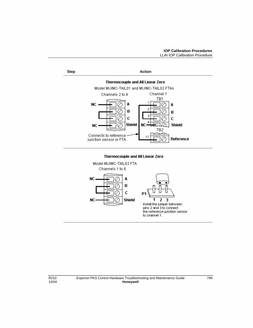
IOP Calibration ProceduresLLAI IOP Calibration Procedure
R210 Experion PKS Control Hardware Troubleshooting and Maintenance Guide 79910/04 Honeywell
Step Action
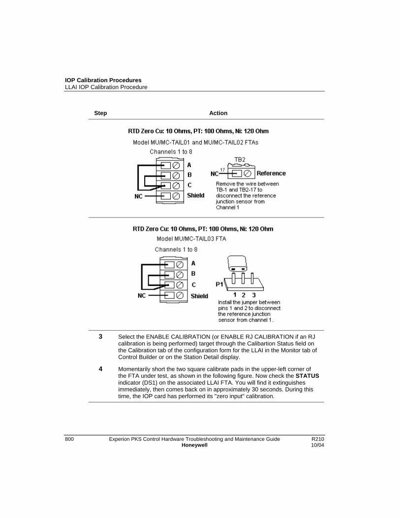
IOP Calibration ProceduresLLAI IOP Calibration Procedure
800 Experion PKS Control Hardware Troubleshooting and Maintenance Guide R210Honeywell 10/04
Step Action
3 Select the ENABLE CALIBRATION (or ENABLE RJ CALIBRATION if an RJcalibration is being performed) target through the Calibartion Status field onthe Calibration tab of the configuration form for the LLAI in the Monitor tab ofControl Builder or on the Station Detail display.
4 Momentarily short the two square calibrate pads in the upper-left corner ofthe FTA under test, as shown in the following figure. Now check the STATUSindicator (DS1) on the associated LLAI FTA. You will find it extinguishesimmediately, then comes back on in approximately 30 seconds. During thistime, the IOP card has performed its "zero input" calibration.

IOP Calibration ProceduresLLAI IOP Calibration Procedure
R210 Experion PKS Control Hardware Troubleshooting and Maintenance Guide 80110/04 Honeywell
Step Action
5 Remove the "zero inputs" and replace them with full-scale signals. Refer tothe appropriate figure that follows for the full scale input value and theconnection to the screw or compression terminals.
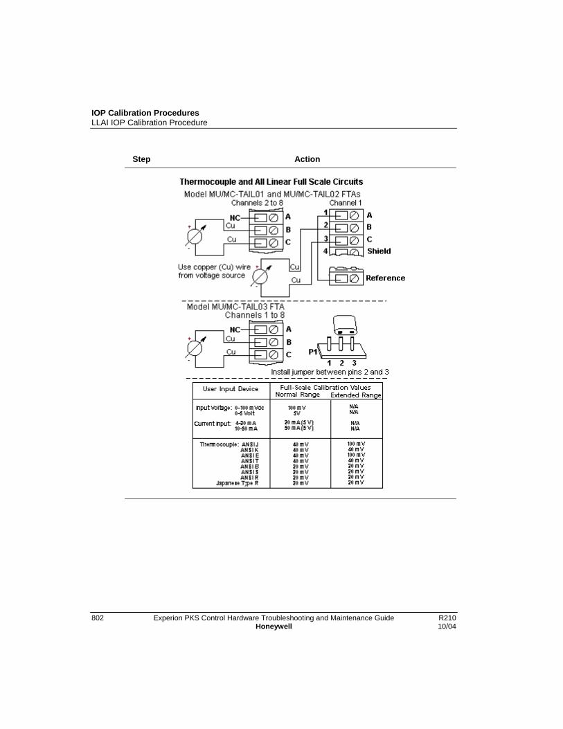
IOP Calibration ProceduresLLAI IOP Calibration Procedure
802 Experion PKS Control Hardware Troubleshooting and Maintenance Guide R210Honeywell 10/04
Step Action
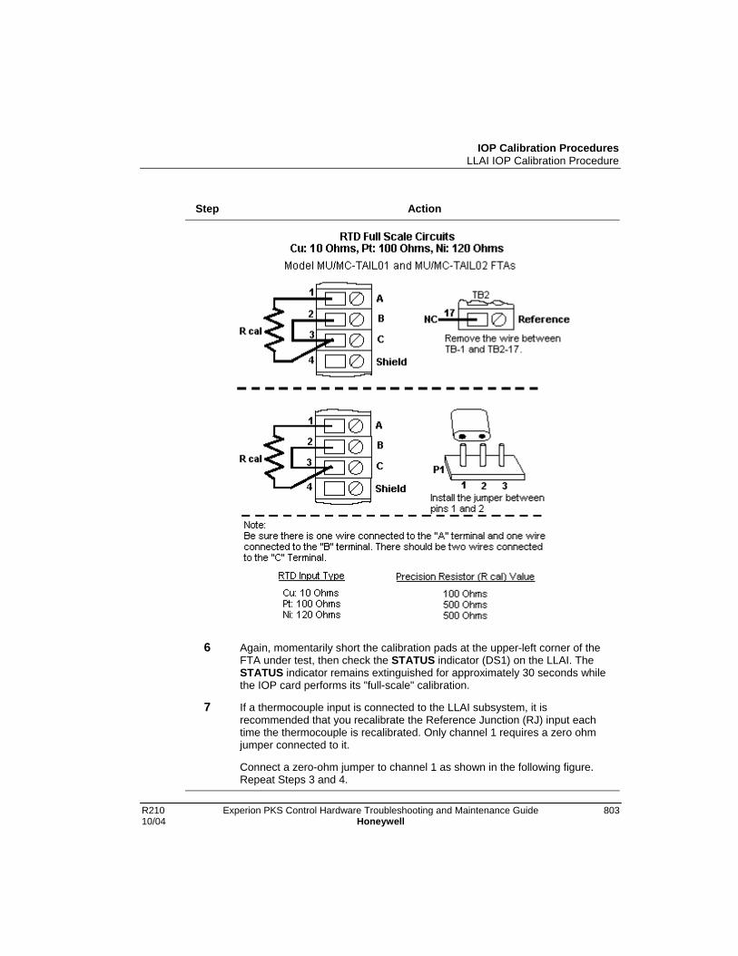
IOP Calibration ProceduresLLAI IOP Calibration Procedure
R210 Experion PKS Control Hardware Troubleshooting and Maintenance Guide 80310/04 Honeywell
Step Action
6 Again, momentarily short the calibration pads at the upper-left corner of theFTA under test, then check the STATUS indicator (DS1) on the LLAI. TheSTATUS indicator remains extinguished for approximately 30 seconds whilethe IOP card performs its "full-scale" calibration.
7 If a thermocouple input is connected to the LLAI subsystem, it isrecommended that you recalibrate the Reference Junction (RJ) input eachtime the thermocouple is recalibrated. Only channel 1 requires a zero ohmjumper connected to it.
Connect a zero-ohm jumper to channel 1 as shown in the following figure.Repeat Steps 3 and 4.
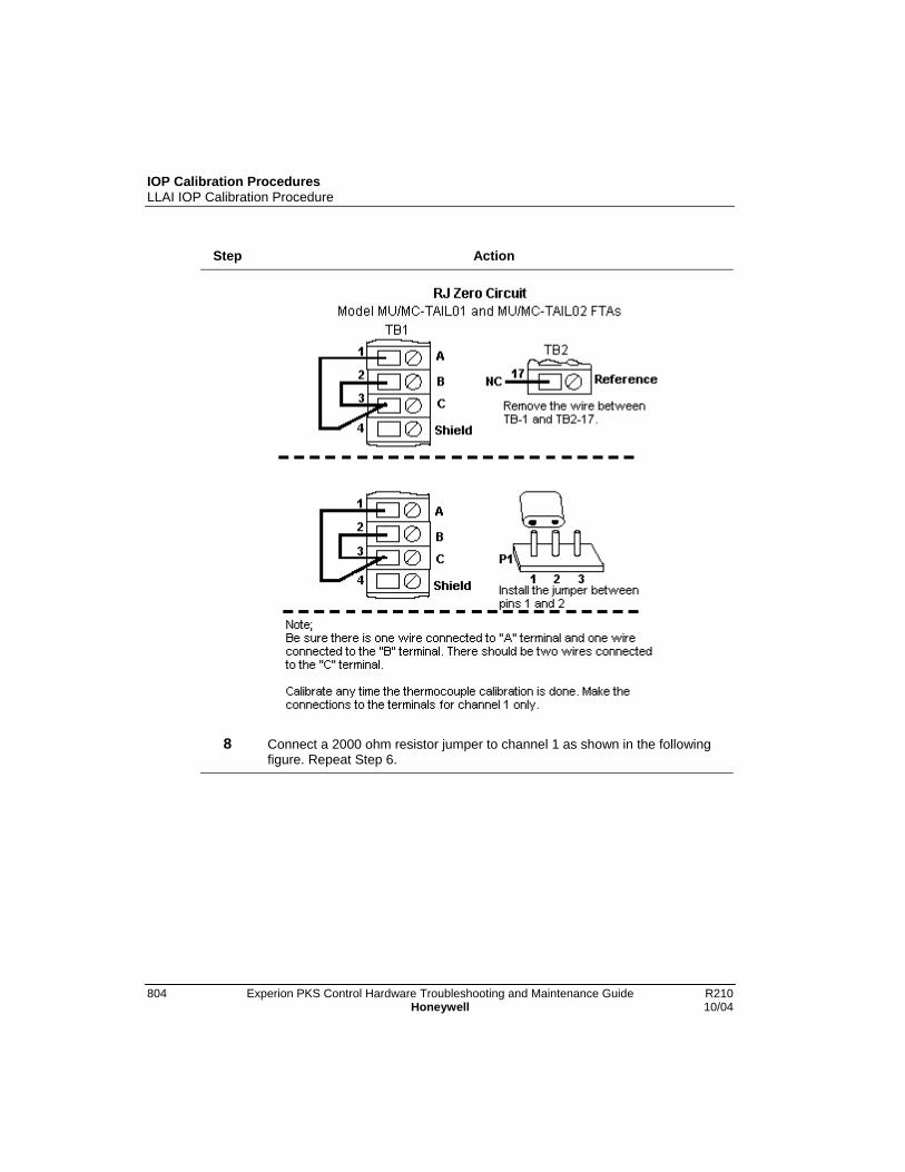
IOP Calibration ProceduresLLAI IOP Calibration Procedure
804 Experion PKS Control Hardware Troubleshooting and Maintenance Guide R210Honeywell 10/04
Step Action
8 Connect a 2000 ohm resistor jumper to channel 1 as shown in the followingfigure. Repeat Step 6.

IOP Calibration ProceduresLLAI IOP Calibration Procedure
R210 Experion PKS Control Hardware Troubleshooting and Maintenance Guide 80510/04 Honeywell
Step Action
9 Be sure the target through the Calibartion Status field on the Calibration tabof the configuration form for the LLAI in the Monitor tab of Control Builder oron the Station Detail display has returned to ENABLE CALIBRATION,indicating that the zero and span calibration process has completed.
10 Check the LLAI IOP card for Soft failures. If a Soft failure occurred, find thesource of the failure, correct it, and repeat the calibration procedure. If noneoccurred, remove the test equipment from the FTA and reconnect the fieldwiring. If the FTA has screw terminal strips, replace the plastic cover over thestrips.

IOP Calibration ProceduresLLAI IOP Calibration Procedure
806 Experion PKS Control Hardware Troubleshooting and Maintenance Guide R210Honeywell 10/04
Step Action
11 Inform the operator that the LLAI subsystem can be returned to on-lineoperation.

IOP Calibration ProceduresNonredundant HLAI IOP Calibration Procedure
R210 Experion PKS Control Hardware Troubleshooting and Maintenance Guide 80710/04 Honeywell
Nonredundant HLAI IOP Calibration Procedure
About HALI procedure
The following calibration procedure is written for the nonredundant model MU-TAIH02or MU-TAIH03 HLAI FTA, but the procedure can also be used for the redundant modelMU-TAIH12, MU-TAIH13, MU-TAIH22, MU-TAIH23, MU-TAIH52, MU-TAIH53,MU-TAIH62, MU-GAIH12/82, MU-GAIH13/83, MU-GAIH14/84, and MU-GAIH22/92FTAs.
SHOCK HAZARD
Calibration may require access to hazardous live circuits and should only beperformed by a qualified service person. More than one switch may berequired to deenergize units before calibration.
Galvanic isolation FTA connection points
The connection points for the calibration voltage source and the shorting location thatstarts the calibration differs for the model MU-GAIH12/82, MU-GAIH13/83, and MU-GAIH14/84 Galvanically Isolated FTAs. Because of circuit density on the FTA boardassembly, IOP calibration terminals, similar to those on a standard FTA, could not beadded to the assembly. Instead, unused pins in the FTA’s 50-pin auxiliary connector, J19,provide a calibration interface for the Galvanic Isolation HLAI Calibration tool,Honeywell part number 51201450-100. The following table lists the voltage input pinsand calibration start pins and the following figure is an illustration of the tool..
Description Pins
Primary IOP Voltage Source 19 (+) and 44 (-)
Secondary IOP Voltage Source 20 (+) and 45 (-)
Calibration Start (Short together) 21 and 46

IOP Calibration ProceduresNonredundant HLAI IOP Calibration Procedure
808 Experion PKS Control Hardware Troubleshooting and Maintenance Guide R210Honeywell 10/04
Calibration terminals
The signals required for calibration of the HLAI IOP are provided at the screw terminalsat the end of the tool’s cable when the cable is connected to the auxiliary connector onthe HLAI FTA. The calibration procedure is the same procedure used for the standardHLAI FTA.
HLAI calibration procedureUse the following procedure to calibrate a nonredundant HLAI IOP.
ATTENTION
This calibration procedure calibrates all channels simultaneously, rather thaneach channel singularly.
Step Action
1 Put the IOP card in its IDLE state through the Execution State command onits configuration form in the Monitor tab of Control Builder or the Station Detaildisplay.
2 Select the ENABLE CALIBRATION target through the Calibartion Status fieldon the Calibration tab of the configuration form for the HLAI in the Monitor tabof Control Builder or on the Station Detail display.
3 If the voltage source is connected before idling the IOP and enablingcalibration, the HLAI will report a Soft failure. Connect the calibration voltagesource to the FTA and adjust the voltage to 5 Vdc (4.9995 – 5.0005 Vdc).See the following figures for the assembly layout of the nonredundant modelMU-TAIH02 FTA and the redundant model MU-TAIH12 FTA, respectively.The assembly layouts of all the HLAI FTAs are illustrated in the ControlHardware Installation Guide in Knowledge Builder.
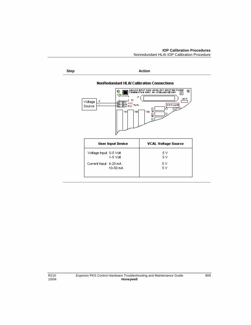
IOP Calibration ProceduresNonredundant HLAI IOP Calibration Procedure
R210 Experion PKS Control Hardware Troubleshooting and Maintenance Guide 80910/04 Honeywell
Step Action

IOP Calibration ProceduresNonredundant HLAI IOP Calibration Procedure
810 Experion PKS Control Hardware Troubleshooting and Maintenance Guide R210Honeywell 10/04
Step Action
IOP Calibration ProceduresNonredundant HLAI IOP Calibration Procedure
R210 Experion PKS Control Hardware Troubleshooting and Maintenance Guide 81110/04 Honeywell
Step Action
4 Short the two calibration pads at the upper-left corner of the HLAI FTA to startthe calibration. For the Galvanically Isolated FTAs, two pins in theMarshalling Panel connector are shorted together.
5 Be sure the calibration target on the form in Monitor tab of Control Builder orStation Detail display has changed back to ENABLE CALIBRATION,indicating that thezero and span calibration process has completed. Checkfor the Soft failure CALIB ABORT, which indicates bad calibration.
6 Disconnect the calibration voltage source wiring.
7 Inform the operator that the HLAI can be returned to on-line operation.

IOP Calibration ProceduresRedundant HLAI IOP Calibration Procedure
812 Experion PKS Control Hardware Troubleshooting and Maintenance Guide R210Honeywell 10/04
Redundant HLAI IOP Calibration Procedure
Simultaneous HLAI IOP calibration
Recalibrate each HLAI IOP separately with an off-line Controller or follow the previousprocedure for nonredundant High Level Analog Input FTA to simultaneously calibrateboth IOPs. The calibration voltage source must be connected to both sets of calibrationterminals on the redundant model FTA simultaneously with parallel wiring as shown inthe figure in the previous procedure for the model MU-TAIH12 FTA.
SHOCK HAZARD
Calibration may require access to hazardous live circuits and should only beperformed by a qualified service person. More than one switch may berequired to deenergize units before calibration.

IOP Calibration ProceduresNonredundant AO IOP Calibration Procedure
R210 Experion PKS Control Hardware Troubleshooting and Maintenance Guide 81310/04 Honeywell
Nonredundant AO IOP Calibration Procedure
About AO procedure
This calibration procedure is written with the nonredundant model MU-TAOX02 as anexample, but the procedure can also be used for the nonredundant model MU-GAOX02,and MU-GAOX72 FTAs, and the redundant model MU-TAOX12, MU-TAOX52, MU-GAOX12, and MU-GAOX82 FTAs.
AO calibration procedureUse the following procedure to calibrate an Analog Output IOP.
Step Action
1 Isolate the AO IOP outputs. Use an Analog Standby Manual device to controlthe devices connected to the FTA. The Analog Standby Manual deviceprovides isolation from the IOP outputs.
2 Put the IOP card in its IDLE state through the Execution State command onits configuration form in the Monitor tab of Control Builder or the Station Detaildisplay.
3 Select the ENABLE CALIBRATION target through the Calibartion Status fieldon the Calibration tab of the configuration form for the HLAI in the Monitor tabof Control Builder or on the Station Detail display.
4 Connect an adjustable floating voltage source to the FTA output terminals asshown in the following figures for the nonredundant model MU-TAOX02 FTAor redundant model MU-TA0X12, respectively. Adjust the voltage source tobetween 4.9995 and 5.0005 Vdc. The AO IOP uses this precision voltagereference to do an accurate short term calibration of the internal loopbackADC. The circuitry is then used to calibrate each output channel.
(See the Control Hardware Installation Guide for layouts of other model AOFTAs.)

IOP Calibration ProceduresNonredundant AO IOP Calibration Procedure
814 Experion PKS Control Hardware Troubleshooting and Maintenance Guide R210Honeywell 10/04
Step Action
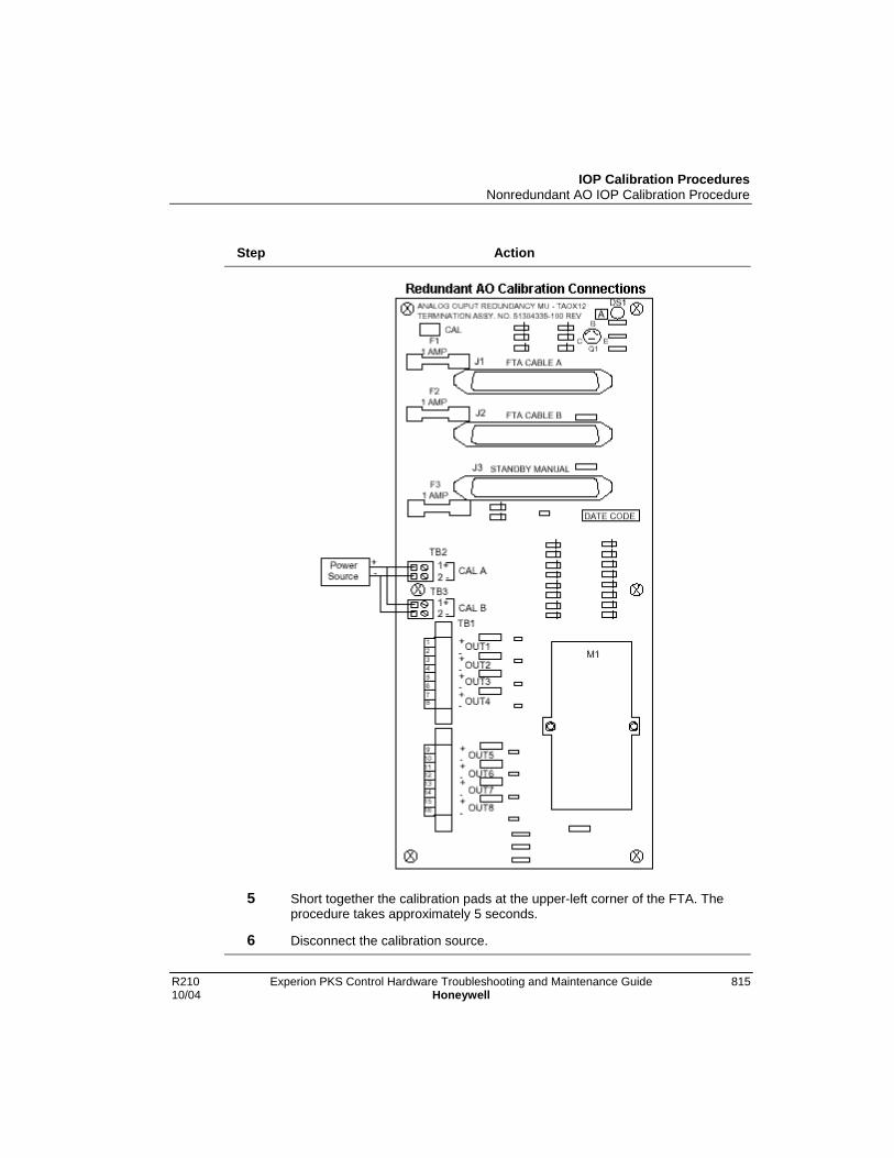
IOP Calibration ProceduresNonredundant AO IOP Calibration Procedure
R210 Experion PKS Control Hardware Troubleshooting and Maintenance Guide 81510/04 Honeywell
Step Action
5 Short together the calibration pads at the upper-left corner of the FTA. Theprocedure takes approximately 5 seconds.
6 Disconnect the calibration source.
IOP Calibration ProceduresNonredundant AO IOP Calibration Procedure
816 Experion PKS Control Hardware Troubleshooting and Maintenance Guide R210Honeywell 10/04
Step Action
7 Inform the operator that the AO IOP can be placed in control.

IOP Calibration ProceduresRedundant AO IOP Calibration Procedure
R210 Experion PKS Control Hardware Troubleshooting and Maintenance Guide 81710/04 Honeywell
Redundant AO IOP Calibration Procedure
Simultaneous AO IOP calibration
Follow the previous nonredundant Analog Output FTA calibration procedure tosimultaneously calibrate both IOPs. The calibration voltage source must be connected toboth sets of calibration terminals on the redundant model FTA simultaneously withparallel wiring as shown in the redundant AO calibration connections figure in theprevious procedure.
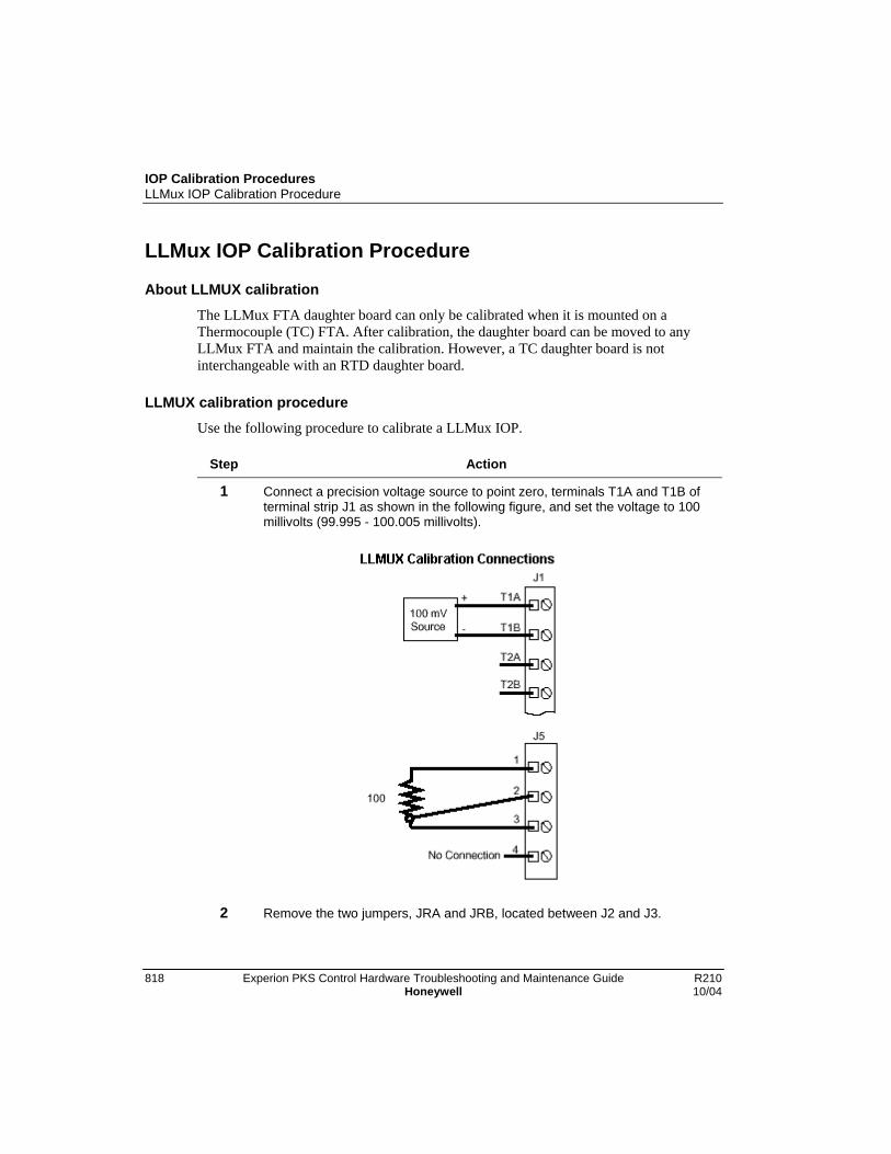
IOP Calibration ProceduresLLMux IOP Calibration Procedure
818 Experion PKS Control Hardware Troubleshooting and Maintenance Guide R210Honeywell 10/04
LLMux IOP Calibration Procedure
About LLMUX calibration
The LLMux FTA daughter board can only be calibrated when it is mounted on aThermocouple (TC) FTA. After calibration, the daughter board can be moved to anyLLMux FTA and maintain the calibration. However, a TC daughter board is notinterchangeable with an RTD daughter board.
LLMUX calibration procedureUse the following procedure to calibrate a LLMux IOP.
Step Action
1 Connect a precision voltage source to point zero, terminals T1A and T1B ofterminal strip J1 as shown in the following figure, and set the voltage to 100millivolts (99.995 - 100.005 millivolts).
2 Remove the two jumpers, JRA and JRB, located between J2 and J3.

IOP Calibration ProceduresLLMux IOP Calibration Procedure
R210 Experion PKS Control Hardware Troubleshooting and Maintenance Guide 81910/04 Honeywell
Step Action
3 Connect the precision resistor (three lead 100 ohm ± .005 ohm) to the remoteCJR terminals, J5. Apply power for 5 minutes.
4 Calibration is initiated by a single command for each FTA. Put the IOP card inits IDLE state through the Execution State command on its configuration formin the Monitor tab of Control Builder or the Station Detail display.
5 Select the ENABLE CALIBRATION target through the Calibartion Status fieldon the Calibration tab of the configuration form for the LLMUX in the Monitortab of Control Builder or on the Station Detail display. The calibrationprocedure is automatic and completes in less than one second.
6 Remove the voltage source. Disconnect the precision resistor from J5 andreconnect the jumpers removed from JRA and JRB in Step 2.

IOP Calibration ProceduresRHMUX IOP Calibration Procedure
820 Experion PKS Control Hardware Troubleshooting and Maintenance Guide R210Honeywell 10/04
RHMUX IOP Calibration Procedure
About RHMUX calibration
The main calibration constants for the Remote Hardened Low Level Multiplexer(RHMUX) IOP are determined during factory calibration and are used to calibrate thegain block error and the A/D reference.
A subsequent field calibration calibrates only the A/D reference and is done only for the100 mV range which results in the field calibration factor being set to a ratio of theoriginal factory calibration gain to the field calibration gain. This factor is then used tomodify the original factory calibration constants such that the original factory calibrationgain constants still exist.
RHMUX calibration method
The input to the RHMUX IOP is calibrated by using two input voltages for each scale,one at 20% of full range, and on at 80% of full scale. The RHMUX IOP will check to seeif the voltage that is present is within 20% of what is expected for each step in thecalibration procedure.
If the input voltage is out of the expected voltage range, a signal with the led and in thecase of automated factory calibration is generated. When the input voltage isdigitized, thefirmware will take 34 readings, eliminate the highest and lowest readings, and averagethe remaining readings. The gain can then be computed from the factor: DeltaInput/Delta Expected. The resultant gain constants are stored in nonvolatile memorywithin the RHMUX IOP microprocessor. The field calibration factor is also set to 1.
If field calibration is performed at 50 hertz, rather than 60 hertz, the calibrationcoefficients have a ratio of 545/655 prior to storage. This figure is not the exact ratio of50 hertz to 60 hertz because of a peculiarity in the A/D converter in the RHMUX IOP.Since calibration coefficients are stored just for 60 hertz, the firmware compensatesaccordingly when 50 hertz operation for the RHMUX IOP is selected.
In all cases, millivolts are computed as:
(A/D Counts - ZERO Counts) x GAIN.
GAIN is determined at calibration time as:
Factory mV/Count) x (Field Calibration Factor) x (50 Hz/60 Hz Factor)
IOP Calibration ProceduresRHMUX IOP Calibration Procedure
R210 Experion PKS Control Hardware Troubleshooting and Maintenance Guide 82110/04 Honeywell
Field calibration overview
The field calibration procedure is designed with the assumption that the RHMUX FTAmay be some distance from the control room and the console when calibration isperformed. Therefore, the procedure provides for all the interaction between the personperforming the calibration and the RHMUX FTA when the initial calibration command isexecuted at the console and the tasks that must be performed locally at the RHMUXFTA.
In addition, the RHMUX IOP will not exit the calibration sequence if it is unsuccessful,but rather remains at the failed step in the calibration sequence in order to allow it to berepeated. This means that in order to use the RHMUX IOP again, or restart thecalibration sequence, power to the RHMUX IOP must be cycled off and then on again.
RHMUX calibration procedureUse the following procedure to calibrate an RHMUX IOP.
Step Action
1 Put the IOP card in its IDLE state through the Execution State command onits configuration form in the Monitor tab of Control Builder or the Station Detaildisplay.
2 Verify on the RHMUX configuration form in the Monitor tab of Control builderthat the IOP is configured for the correct frequency.
3 Disconnect any field wires from channels 1 and 16.
4 Select the ENABLE CALIBRATION target through the Calibartion Status fieldon the Calibration tab of the configuration form for the RHMUX in the Monitortab of Control Builder or on the Station Detail display.
5 At the RHMUX FTA, verify that the voltage at the factory calibration pin is alogic one which indicates that field calibration is in process.
Verify that the FTA’s Status LED is off and not blinking randomly.
6 Connect the calibration device to the channel 1 input terminals. Set thevoltage to 100 mV, +/- 5 microvolts.
7 Short the channel 16 input terminals for a minimum of 0.1 of a second andthen remove the short. The firmware uses burnout to read the state of thechannel 16 input. The multiplexer digitizes the input in about 4 seconds, turnson the Status LED for 0.2 seconds, and turns the Status LED off if the voltageis within 20% of the expected voltage. If not, the Status LED will blink twice.

IOP Calibration ProceduresRHMUX IOP Calibration Procedure
822 Experion PKS Control Hardware Troubleshooting and Maintenance Guide R210Honeywell 10/04
Step Action
8 Set the calibration voltage to 20 mV, +/- 5 uV. Short the channel 16 terminalsagain for a minimum of 0.1 of a second and then remove the short. TheRHMUX IOP will do another conversion. The firmware extracts a new slopecoefficient for the reference diode and overwrites the field the previous fieldcalibration factor.
9 If the calibration is successful and complete, the Status LED returns to thenormal blinking cycle. The RHMUX IOP will respond to a “Status” commandwith an “OK” status. If the calibration was not successful, the response will be“CALIBRATION FAILURE.”
RHMUX calibration failure
If during the calibration procedure, the RHMUX IOP senses that the calibration voltageis off by more than 20%, the Status LED will blink twice (0.2 of a second on, 0.2 of asecond off) to indicate a failure. This requires that the calibration voltage be checked andreset to the proper value. Again, the channel 16 input terminals must be shorted for aminimum of 0.1 of a second and then opened to cause the RHMUX IOP to retry thevoltage. If the calibration sequence can not be successfully completed, power must becycled off and then on again to exit the calibration sequence.
IOP Calibration ProceduresThermocouple Input Accuracy Verification
R210 Experion PKS Control Hardware Troubleshooting and Maintenance Guide 82310/04 Honeywell
Thermocouple Input Accuracy Verification
About thermocouple verification
It is necessary to verify the accuracy of a thermocouple input. Verification isaccomplished with the use of a precision Thermocouple Simulator, the instrument’soperating procedure, and the procedure steps that follow.
Thermocouple verification procedurePerform the following steps to verify the accuracy of the thermocouple.
Step Action
1 Be sure the equipment is properly installed in the cabinet.
2 Connect a reference grade thermocouple wire between the ThermocoupleSimulator and one input of the process control system.
3 Install all equipment covers and close the cabinet doors.
4 Using the applicable configuration form in the Montior tab of Control Builder,disable the Open Thermocouple Detection mode for the control point.
5 Allow the equipment to operate normally for 2 hours while temperaturegradients stabilize.
6 Verify the accuracy of the thermocouple using the Thermocouple Simulatorand following its operating procedure.
7 Move the thermocouple reference wire to another thermocouple input fromthe process control system and repeat the above procedures, starting at Step3.

IOP Calibration ProceduresThermocouple Input Accuracy Verification
824 Experion PKS Control Hardware Troubleshooting and Maintenance Guide R210Honeywell 10/04
R210 Experion PKS Control Hardware Troubleshooting and Maintenance Guide 82510/04 Honeywell
Periodic IOP Redundancy Tests
Overview
About redundancy tests
This section describes the recommended periodic verification of the equipment’sredundancy where applicable.
At an appropriate time, such as during a annual period of scheduled plant maintenance,the Process Manager I/O subsystem’s availability can be improved by performingspecific tests on various hardware parts of the Process Manager I/O subsystem. Duringthe tests, personnel should be prepared for either proper operation or improper operationof the hardware. The preparation for improper operation of the hardware during the testsyields the lowest Mean Time to Repair (MTR), which is important when maximizingsubsystem availability.
Even though fault coverage is high in the process control system during normaloperation, periodic redundancy testing provides additional fault coverage by exercisingany hardware that is not in use during normal operation.
Monitor displays
You can monitor and interact with a redundant Input/Output Processor (IOP) through itsconfiguration form in the Monitor tab of Control Builder or its Station Detail display.The following figure shows the main tab of the configuration form for an Analog OutputIOP in the Monitor tab of Control Builder. The figure is for example purposes only doesnot represent actual indications.

Periodic IOP Redundancy TestsOverview
826 Experion PKS Control Hardware Troubleshooting and Maintenance Guide R210Honeywell 10/04
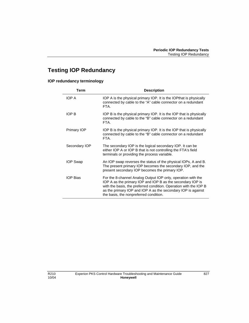
Periodic IOP Redundancy TestsTesting IOP Redundancy
R210 Experion PKS Control Hardware Troubleshooting and Maintenance Guide 82710/04 Honeywell
Testing IOP Redundancy
IOP redundancy terminology
Term Description
IOP A IOP A is the physical primary IOP. It is the IOPthat is physicallyconnected by cable to the “A” cable connector on a redundantFTA.
IOP B IOP B is the physical primary IOP. It is the IOP that is physicallyconnected by cable to the “B” cable connector on a redundantFTA.
Primary IOP IOP B is the physical primary IOP. It is the IOP that is physicallyconnected by cable to the “B” cable connector on a redundantFTA.
Secondary IOP The secondary IOP is the logical secondary IOP. It can beeither IOP A or IOP B that is not controlling the FTA’s fieldterminals or providing the process variable.
IOP Swap An IOP swap reverses the status of the physical IOPs, A and B.The present primary IOP becomes the secondary IOP, and thepresent secondary IOP becomes the primary IOP.
IOP Bias For the 8-channel Analog Output IOP only, operation with theIOP A as the primary IOP and IOP B as the secondary IOP iswith the basis, the preferred condition. Operation with the IOP Bas the primary IOP and IOP A as the secondary IOP is againstthe basis, the nonpreferred condition.

Periodic IOP Redundancy TestsTesting IOP Redundancy
828 Experion PKS Control Hardware Troubleshooting and Maintenance Guide R210Honeywell 10/04
Test procedureUse the following procedure to test each redundant IOP configuration.
Step Action
1 In Monitor tab of Control Builder, double-click applicable IOP icon to open itsconfiguration form.
2 On the Main tab, check the current status of IOP Partner A and IOP PartnerB.
3 • Click the Swap Primary IOP button.
• Check that the status of IOP Partner A and IOP Parnter B is switchedaccordingly.
4 Click the Swap Primary IOP button again to restore the status noted in Step2.
5 Repeat this procedure for other redundant pairs of IOPs.
Periodic IOP Redundancy TestsRedundant 8-Channel Analog Output IOPs
R210 Experion PKS Control Hardware Troubleshooting and Maintenance Guide 82910/04 Honeywell
Redundant 8-Channel Analog Output IOPs
About redundancy bias
Redundancy for the 8-channel Analog Output IOPs is biased toward the IOP A tomaximize reliability. Hardware bias is preferred because IOP B (the physical secondary)is connected to the Analog Output FTA through a switching module on the FTA, whileIOP A (the physical primary) is connected directly to the FTA circuitry that interfaces theFTA’s field wiring output terminals. Use of the procedure in this subsection tests aredundant pair of Analog Output IOPs for proper operation.
Hardware identificationLocate the following components.
• Analog Output IOP A
• Analog Output IOP B
• The redundant Analog Output FTA
• An Analog Output Standby Manual device
• Devices that are being controlled by the analog output of the FTA
• Control algorithms that are driving the analog outputs
Status check
Using the IOP configuration form in the Monitor tab of Control Builder, check that theIOPs are currently operating normally, as indicated by a status of OK/BKP. In addition,be sure the following is true.
• The outputs are being controlled by IOP A
• IOP A and IOP B are synchronized
• IOP A is operating normally without Soft failures
• IOP B is operating normally without Soft failures
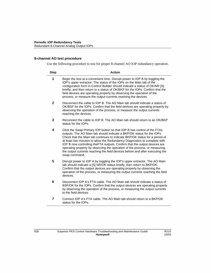
Periodic IOP Redundancy TestsRedundant 8-Channel Analog Output IOPs
830 Experion PKS Control Hardware Troubleshooting and Maintenance Guide R210Honeywell 10/04
8-channel AO test procedureUse the following procedure to test for proper 8-channel AO IOP redundancy operation.
Step Action
1 Begin the test at a convenient time. Disrupt power to IOP B by toggling theIOP’s upper extractor. The status of the IOPs on the Main tab of theconfiguration form in Control Builder should indicate a status of OK/NR [S]briefly, and then return to a status of OK/BKP for the IOPs. Confirm that thefield devices are operating properly by observing the operation of theprocess, or measure the output currents reaching the devices.
2 Disconnect the cable to IOP B. The AO Main tab should indicate a status ofOK/BSF for the IOPs. Confirm that the field devices are operating properly byobserving the operation of the process, or measure the output currentsreaching the devices.
3 Reconnect the cable to IOP B. The AO Main tab should return to an OK/BKPstatus for the IOPs.
4 Click the Swap Primary IOP button so that IOP B has control of the FTAsoutputs. The AO Main tab should indicate a BKP/OK status for the IOPs.Check that the Main tab continues to indicate BKP/OK status for a period ofat least two minutes to allow the Redundancy Diagnostics to complete withIOP B now controlling theFTA outputs. Confirm that the output devices areoperating properly by observing the operation of the process, or measuringthe output currents reaching the field devices before and after executing theswap command.
5 Disrupt power to IOP A by toggling the IOP’s upper extractor. The AO Maintab should indicate a [S] NR/OK status briefly, then return to BKP/OK.Confirm that the output devices are operating properly by observing theoperation of the process, or measuring the output currents reaching the fielddevices.
6 Disconnect IOP A’s FTA cable. The AO Main tab should indicate a status ofBSF/OK for the IOPs. Confirm that the output devices are operating properlyby observing the operation of the process, or measuring the output currentsto the field devices.
7 Connect IOP A’s FTA cable. The AO Main tab should return to a BKP/OKstatus for the IOPs.
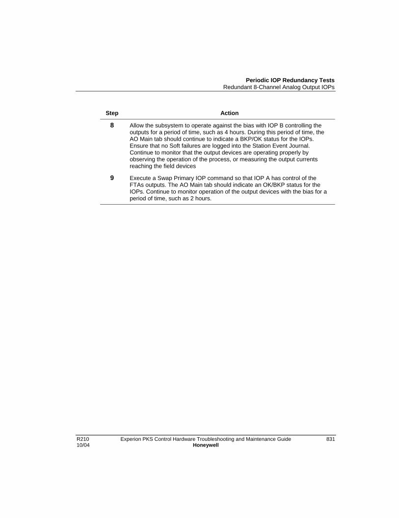
Periodic IOP Redundancy TestsRedundant 8-Channel Analog Output IOPs
R210 Experion PKS Control Hardware Troubleshooting and Maintenance Guide 83110/04 Honeywell
Step Action
8 Allow the subsystem to operate against the bias with IOP B controlling theoutputs for a period of time, such as 4 hours. During this period of time, theAO Main tab should continue to indicate a BKP/OK status for the IOPs.Ensure that no Soft failures are logged into the Station Event Journal.Continue to monitor that the output devices are operating properly byobserving the operation of the process, or measuring the output currentsreaching the field devices
9 Execute a Swap Primary IOP command so that IOP A has control of theFTAs outputs. The AO Main tab should indicate an OK/BKP status for theIOPs. Continue to monitor operation of the output devices with the bias for aperiod of time, such as 2 hours.

Periodic IOP Redundancy TestsPower Cable Redundancy
832 Experion PKS Control Hardware Troubleshooting and Maintenance Guide R210Honeywell 10/04
Power Cable RedundancyAbout power cables
The IOP Card files, the Digital Input Power Distribution assembly, and the GalvanicIsolation Power Distribution assembly are provided with redundant power cables toenhance power distribution reliability within the Process Manager I/O subsystem. Youshould be able to disconnect either end of one of the two power cables providing powerto the card file, Digital Input Power Distribution assembly, or Galvanic Isolation PowerDistribution assembly without affecting equipment operation.
Power cable redundancy testing should be performed during a plantshutdown.
Testing power cable redundancy
Perform the following steps for each IOPcard file, Digital Input Power Distributionassembly, and Galvanic Isolation Power Distribution assembly.
Step Action
1 Disconnect one of the pair of power cables for a card file, Digital Input PowerDistribution assembly, or Galvanic Isolation Power Distribution assembly ateither the Power System connection or the other end of the cable. Determineif the operation of the equipment is impaired by observing the operation of theaffected IOP cards.
2 Replace the cable connection and then disconnect the other cable in the pair.Determine if the operation of the equipment is impaired.
3 Repeat Steps 1 and 2 for all card files, Digital Input Power Distributionassemblies, and Galvanic Isolation Power Distribution assemblies.

Periodic IOP Redundancy TestsPower Supply Module Redundancy
R210 Experion PKS Control Hardware Troubleshooting and Maintenance Guide 83310/04 Honeywell
Power Supply Module Redundancy
About power system redundancy
A Power System with redundant Power Supply Modules should continue to providepower to the High-Performance Process Manager without interruption when one of thePower Supply Modules fails or looses ac power.
Power system redundancy testing should be performed during aplant shutdown.
Testing power system redundancy procedurePerform the following steps to test the Power System’s redundancy power capability.
Step Action
1 With the both Power Supply Modules of a redundant Power Systemoperating, place the ON/OFF switch of the right Power Supply Module in theOFF position. Observe that the IOP cards continue to operate normally (theirStatus and Power indicators are illuminated). Return the ON/OFF switch tothe ON position, if operation continues normally. Should the IOP cards notcontinue to operate normally, check cables and/or replace the Power SupplyModule.
ATTENTION
When the left Power Supply Module’s ON/OFF switch is placed in the OFFposition, all Low Level Analog Input IOPs should report a Soft failure, but theywill continue to operate normally.
2 With the both Power Supply Modules of a redundant Power Systemoperating, place the ON/OFF switch of the left Power Supply Module in theOFF position. Observe that the IOP cards continue to operate normally (theirStatus and Power indicators are illuminated). Return the ON/OFF switch tothe ON position, if operation continues normally. Should the IOP cards notcontinue to operate normally, check cables and/or replace the Power SupplyModule.

Periodic IOP Redundancy TestsPower Supply Module Redundancy
834 Experion PKS Control Hardware Troubleshooting and Maintenance Guide R210Honeywell 10/04
R210 Experion PKS Control Hardware Troubleshooting and Maintenance Guide 83510/04 Honeywell
System Performance and Tuning Considerations
System Performance FeaturesSome of these features are controlled by system configuration and licensing. Others areonly automatically applicable when the system is ordered with the Installation ServicesOption. Without this option, some features require customer care and intervention.
PC Qualification/InstallationServices
The ability to Attain system Performance, Availability, andReliability, starts at the ground level with PC Platform.
Honeywell works with Dell to build PCs to specifications tomeet the needs of Process Control Systems. Althoughbased on systems available to the General Public, thesesystems will typically include such items as Error CorrectingMemory, internal hardware sensors, managementapplications, and other features that differentiate them fromthe typical household or business PC. Once built, thesesystems are then brought in for evaluation and testing.
Honeywell then tests these platforms to verify that they meetcertain Environmental and regulatory standards. This isnecessary to verify that the PC will work in all types ofProcess Control scenarios.
Qualification continues with the Operating Systeminstallation. How the system performs is very dependent onthe OS software configuration, which includes the devicedrivers that interact with the hardware. Many performancecharacteristics are derived from this interaction, while alsoworking towards optimizing the user experience.
Offered via the Honeywell Installation Services option, thedata from the qualification effort is included in the OperatingSystem installation CDs, called NT5Plus. If you have notordered the system with NT5Plus, then you should apply thequalified driver set for your PC platform.
The information on hardware drivers and versions ispublished in the Software Change Notice (SCN) for theRelease. If you are unable to attain the specified driverversions, call the Honeywell Technical Assistance Center.
RedundantNetworking
A configuration option, it protects the system from networkfaults. The system monitors the network status and will
System Performance and Tuning ConsiderationsSystem Performance Features
836 Experion PKS Control Hardware Troubleshooting and Maintenance Guide R210Honeywell 10/04
automatically fail over when the system detects a fault.
Server Redundancy This allows the system to continue operating even when aPC fails which was hosting the Experion PKS Server. Allsystems in the configuration will shift to the backup system ifthe primary node has failed.
• Fast Failover: Some processes need to be moretolerant to total system failure. This option includesmore stringent monitoring of the two servers and a fasterswitchover time.
• Redundant Engineering Repository (Process Systems):When the Redundant Server option is chosen onProcess Systems, you automatically get redundantEngineering Repositories. This is a database of Controlinformation and configuration items which are critical inoperation on these type of systems.
Multi-User/LocationControl Builder(Process Systems)
An application to define process configurations and monitorstatus, the system supports up to 4 of these applicationsrunning on separate nodes in the system.
MultipleClients/Stations
The system supports up to 20 Stations for Process and 40for SCADA systems.
Integrated Security An integrated security model limits on who can changeparameters that effect the control environment.
Fast Recovery/Re-Installation(NT5Plus)
Should a PC hardware failure occur and the system waspurchased with Installation Services, the NT5Plus installationCD can be used to reinstall the system’s configuration in ashort period of time.
System Performance and Tuning ConsiderationsOperating System Tuning
R210 Experion PKS Control Hardware Troubleshooting and Maintenance Guide 83710/04 Honeywell
Operating System TuningSystems ordered with Installation Services (NT5Plus) already have these settings appliedfor the Operational Phase. NT5Plus installed systems will benefit from the settingsmentioned below only during the Configuration Phase of the system. Those systemswhich have not had any of the settings applied will benefit from the settings describedbelow given the systems intended usage and Phase. All settings must be applied with aUser Account logged in that has Administrative Privileges on the system being tuned.
Service/Kernel Tuning
Windows 2000 Professional
Three types of systems are supported on Windows 2000 Professional; Server,Engineering Workstation, and Client. Server can be comprised of the Experion PKSServer Components or the Engineering Repository/SQL (Process Systems only)components. Engineering Workstation (Process Systems only) is comprised of ControlBuilder and Engineering Repository/SQL components. Clients are systems runningStation and/or Control Builder (Process Systems Only).
Kernel Tuning changes the way the Operating System assigns tasking priorities. Twomain areas exist on Professional, Applications or Background Services. The ability tochange this setting is accessed by performing the following steps:
Step Action
1 Locate the My Computer Icon on the Desktop.
2 Right-click the icon and choose properties.
3 On the System Properties Window that appears, choose the Advanced Tab.
4 In the Performance Section, Click the Performance Options Button.
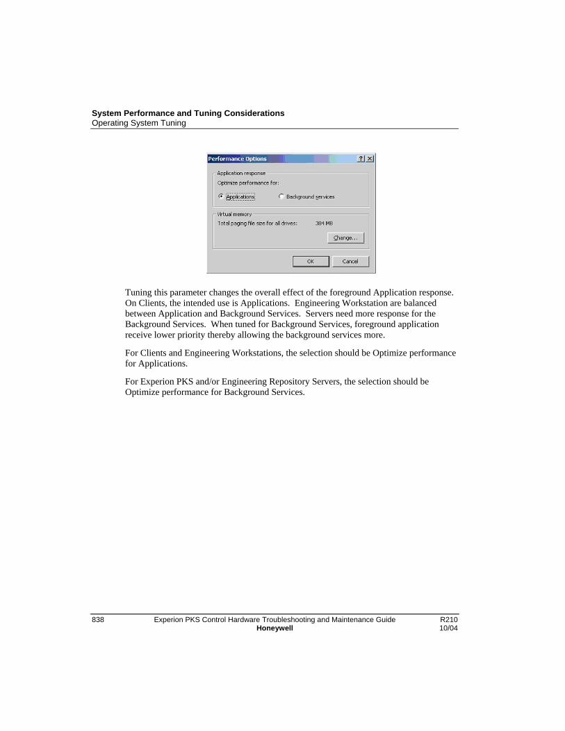
System Performance and Tuning ConsiderationsOperating System Tuning
838 Experion PKS Control Hardware Troubleshooting and Maintenance Guide R210Honeywell 10/04
Tuning this parameter changes the overall effect of the foreground Application response.On Clients, the intended use is Applications. Engineering Workstation are balancedbetween Application and Background Services. Servers need more response for theBackground Services. When tuned for Background Services, foreground applicationreceive lower priority thereby allowing the background services more.
For Clients and Engineering Workstations, the selection should be Optimize performancefor Applications.
For Experion PKS and/or Engineering Repository Servers, the selection should beOptimize performance for Background Services.

System Performance and Tuning ConsiderationsOperating System Tuning
R210 Experion PKS Control Hardware Troubleshooting and Maintenance Guide 83910/04 Honeywell
Windows 2000 Server
Only two types of systems are supported on Windows 2000 Server; Server andEngineering Repository/SQL Server. Server can be comprised of the Experion PKSServer Components and/or the Engineering Repository/SQL (Process Systems only)components. Although Clients can run on the Server itself, they will receive poorperformance. (See the Topologies section of this document for more information.)
Kernel Tuning changes the way the Operating System assigns tasking priorities. Serverallows more tuning options and is actually a two-step process. Step one involves settingthe Application Response. Step two involves tuning the Server Service.
Step Action
1 Application Response:
Adjust the application response. First decide whether or not you will runapplications on your Server. (Control Builder, Station, Excel, etc.) Therecommendation is that you do NOT run applications and configure thesystem as what is called a “Headless” server. (See the Topologies section ofthis document for more information.)
3. Locate the My Computer Icon on the Desktop.
4. Right Click the icon and choose properties.
5. On the System Properties Window that appears, choose the AdvancedTab.
6. In the Performance Section, Click the Performance Options Button.
Tuning this parameter changes the overall effect of the foreground
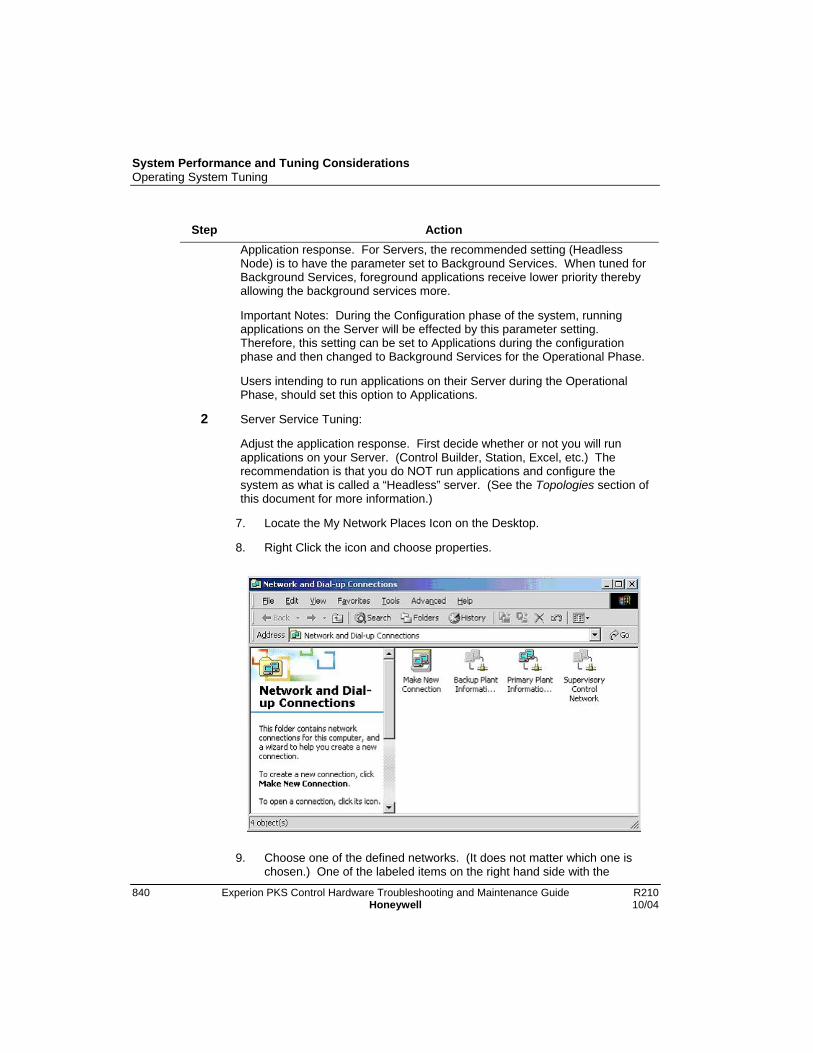
System Performance and Tuning ConsiderationsOperating System Tuning
840 Experion PKS Control Hardware Troubleshooting and Maintenance Guide R210Honeywell 10/04
Step ActionApplication response. For Servers, the recommended setting (HeadlessNode) is to have the parameter set to Background Services. When tuned forBackground Services, foreground applications receive lower priority therebyallowing the background services more.
Important Notes: During the Configuration phase of the system, runningapplications on the Server will be effected by this parameter setting.Therefore, this setting can be set to Applications during the configurationphase and then changed to Background Services for the Operational Phase.
Users intending to run applications on their Server during the OperationalPhase, should set this option to Applications.
2 Server Service Tuning:
Adjust the application response. First decide whether or not you will runapplications on your Server. (Control Builder, Station, Excel, etc.) Therecommendation is that you do NOT run applications and configure thesystem as what is called a “Headless” server. (See the Topologies section ofthis document for more information.)
7. Locate the My Network Places Icon on the Desktop.
8. Right Click the icon and choose properties.
9. Choose one of the defined networks. (It does not matter which one ischosen.) One of the labeled items on the right hand side with the

System Performance and Tuning ConsiderationsOperating System Tuning
R210 Experion PKS Control Hardware Troubleshooting and Maintenance Guide 84110/04 Honeywell
Step Actionfollowing icon associated with it:
10. Right Click it and choose Properities.
11. Highlight (Click On) the File and Printer Sharing for Microsoft Networksand click the Properties button.
Tuning this parameter changes the overall effect of how the system handlesServices. For Servers, the recommended setting (Headless Node) is to havethe parameter set to Maximize data throughput for network applications.
Important Notes: During the Configuration phase of the system, runningapplications on the Server will be effected by this parameter setting. Basedon System Configuration, the following rules can be applied:
On Small Systems and Medium to Large system without the integrated
System Performance and Tuning ConsiderationsOperating System Tuning
842 Experion PKS Control Hardware Troubleshooting and Maintenance Guide R210Honeywell 10/04
Step ActionEngineering Repository (it is on a separate node), this setting can be set toMinimize memory used on small systems during the configuration phase andthen changed to Maximize data throughput for network applications for theOperational Phase.
Medium to Large System configurations with the Integrated EngineeringRepository should set it to Balance during the configuration phase and thenchanged to Maximize data throughput for network applications for theOperational Phase.
On nodes dedicated to running only the Engineering Repository (SQL), thissetting should always be Maximize data throughput for network applications.
Disk Management
Disk performance, or the capability of the system to access and store files on the harddisk, can greatly affect the overall performance of the system. Other than Disk failures,two types of File System (the format of storage on the disk) issues affect the system: FileSystem Errors and Fragmentation.
File System Errors
These can occur frequently during the following events:
• Power Outages
• Improper Shutdown
• Disk Hardware malfunction.
In order to fix the errors, the system must first be set, and then rebooted. (It isrecommended that this operation not be done with the system “On-Control”.)
Perform the following tasks:

System Performance and Tuning ConsiderationsOperating System Tuning
R210 Experion PKS Control Hardware Troubleshooting and Maintenance Guide 84310/04 Honeywell
Step Action
1 Locate and Open the My Computer icon on the desktop by “double” clickingthe icon.
2 Click or highlight the drive you wish to check. Right click it and chooseproperties.
3 Selecting the Tools tab will present the following screen:

System Performance and Tuning ConsiderationsOperating System Tuning
844 Experion PKS Control Hardware Troubleshooting and Maintenance Guide R210Honeywell 10/04
Step Action
4 Click the Check Now button in the Error-Checking section.
5 After making sure the “Automatically fix files system errors” box is checked,

System Performance and Tuning ConsiderationsOperating System Tuning
R210 Experion PKS Control Hardware Troubleshooting and Maintenance Guide 84510/04 Honeywell
Step Actionclick the Start button. Unless a prior check revealed bad sectors, do notcheck the Scan for and attempt recovery of bad sectors.
6 Due to file system locking the drive (NTFS), the system cannot perform thisoption at this time. Click the Yes button to schedule the operation to occurthe next time the system is started.
7 Shutdown and Restart the system. (The check will occur during the Startup.)
After the system returns to the logon prompt, you should log in and check the disk reportin the System’s Event Viewer. If the report contains that it had found bad sectors, thenthe operation should be re-run and the option to “Scan for and attempt recovery of badsectors” should be checked. Drives which continually report bad sectors should bescheduled for replacement. It usually indicates that the drive is experiencing hardwaremalfunctions.
File System Defragmentation
Although the NTFS File system attempts to minimize this problem, it is often the mostfrequent occurring performance issue to occur during normal operation. Basically,fragmentation is the process of when a file or piece of data is written to disk, and it is notwritten contiguously. This causes the system to perform multiple read and lookups everytime the file is accessed. The process of Defragmentation optimizes the file system bymaking each file on the disk occur contiguously. Also, commonly accessed files, such asoperating system or frequently accessed files, are moved to the first sectors on the disk.This enables these files to be found and accessed faster.
Fragmentation will occur frequently and affect performance on Experion PKS Systems.Since the performance of the system is severely degraded during the running of the tasksto fix this performance problem, it should not be done with the system “On-Control”.Administrators of the system should add this maintenance task to the Plant Maintenanceschedule, so that it occurs during Control Shutdowns.
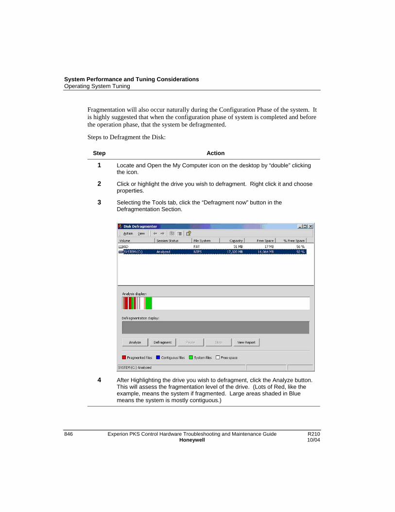
System Performance and Tuning ConsiderationsOperating System Tuning
846 Experion PKS Control Hardware Troubleshooting and Maintenance Guide R210Honeywell 10/04
Fragmentation will also occur naturally during the Configuration Phase of the system. Itis highly suggested that when the configuration phase of system is completed and beforethe operation phase, that the system be defragmented.
Steps to Defragment the Disk:
Step Action
1 Locate and Open the My Computer icon on the desktop by “double” clickingthe icon.
2 Click or highlight the drive you wish to defragment. Right click it and chooseproperties.
3 Selecting the Tools tab, click the “Defragment now” button in theDefragmentation Section.
4 After Highlighting the drive you wish to defragment, click the Analyze button.This will assess the fragmentation level of the drive. (Lots of Red, like theexample, means the system if fragmented. Large areas shaded in Bluemeans the system is mostly contiguous.)
System Performance and Tuning ConsiderationsOperating System Tuning
R210 Experion PKS Control Hardware Troubleshooting and Maintenance Guide 84710/04 Honeywell
Step Action
5 After analysis, you should then defragment the drive either by choosingDefragment now on the recommendation screen, or by reselecting andclicking the Defragment button. Depending on the level of fragmentation andusage, the task may take some time to complete.
ATTENTION
The default fragmentation utility included in Windows 2000 can be upgradedto the full version. Executive Software’s Diskeeper includes a scheduler andthe ability to defragment directories and page files at boot time. Thedefragmentation tasks will effect the Control System if set to run automaticallyvia the Scheduler. Care should be taken when scheduling these events.
Memory and Swapfile
Two types of memory exist in the system; Physical RAM and the Swapfile. Frequently,Multi-tasking operating systems such as Windows 2000, have the ability to take memoryspace occupied by data in physical RAM and swap it into a file. This frees up thephysical RAM for other processes. If the process again requires the data that wasswapped out, a page fault occurs and the page is swapped back from the file into physicalRAM before operation continues. This type of management is called Paging. (And theassociated swapfile is called the page file.)
In Windows 2000 using Task Manager, looking at the Total Limit in the Commit Chargesection of the Performance tab, the Total value is the amount of Physical RAM andSwapfile combined. The Physical Memory section shows how much of the Physicalmemory is available for use.
Page file settings include a lower and upper limit. The lower limit is typically theamount of physical RAM plus management space. This is almost always 1.5 times theamount of physical RAM. The system typically suggests that the upper limit be set toaround 3 times the amount of physical RAM. Windows 2000, in normal operation, willonly use the lower limit size, and hence only the value of the lower limit (Initial Size) ispre-allocated. If the usage exceeds this limit, the system will then continue to allocateadditional space until the upper limit (Maximum Size) is reached or the system runs outof disk space. If this occurs, it usually means that an application/process is leakingmemory.
Some paging of memory for systems is normal. Excessive paging will hurt performanceas there is a hit taken during the swapping and allocation phases. Memory performancecan be degraded during some operations as long as they are not prolonged or part of

System Performance and Tuning ConsiderationsOperating System Tuning
848 Experion PKS Control Hardware Troubleshooting and Maintenance Guide R210Honeywell 10/04
normal system operations. The goal is to produce perfectly balanced systems. Oneswhich have enough physical RAM for normal operations and the ability to Page when anabnormal event is required. Systems who perform paging operations frequently duringnormal operations will receive great performance benefits by adding more physicalRAM.
Honeywell attempts to specify default memory configurations (as published in the SCNof the Release) to minimize paging during normal operations of the system. Scaled viaSmall, Medium, and Large Systems, and then broken up by Operating System, youshould use these tables as a starting point. You should then monitor the Pagefile usage todetermine whether or not your system could benefit from added physical RAM. (SeeSection 6.)
At any time memory is added or removed from the PC, the operating system should beadjusted based on the system type described below.
Client/Station Memory Settings
Based on the Operating System and application usage, this system should not be affectedby paging operations as long as the memory is at the specified amount of 128 MB. Ifadjustments are needed (Section 3.3.4), you should follow the default rules of theOperating System suggestion:
(Example for a 128 MB System)
Initial Size: 192 MB (or default Operating System suggestion.)
Maximum Size: 384 MB (or default Operating System suggestion.)
Servers with 128 MB of Physical RAM or Less.
Based on the Operating System and application usage, this system can be severelyaffected by paging because the amount is less than required. Smaller systems may beable to take this performance hit, but medium to large systems will not be able toadequately perform. Adjustments for this type of system are required for operation.(Section 3.3.4) The settings suggested below should allow the system to run, but amemory upgrade is highly suggested:
Initial Size: 300 MB
Maximum Size: 450 MB
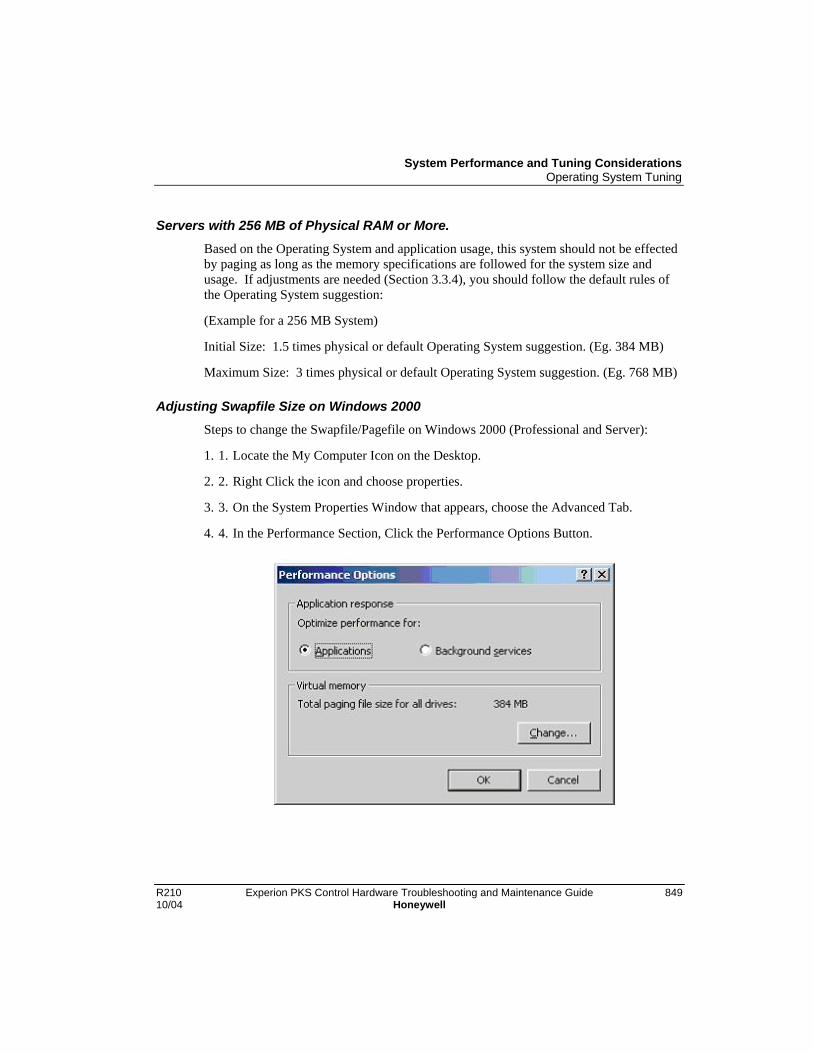
System Performance and Tuning ConsiderationsOperating System Tuning
R210 Experion PKS Control Hardware Troubleshooting and Maintenance Guide 84910/04 Honeywell
Servers with 256 MB of Physical RAM or More.
Based on the Operating System and application usage, this system should not be effectedby paging as long as the memory specifications are followed for the system size andusage. If adjustments are needed (Section 3.3.4), you should follow the default rules ofthe Operating System suggestion:
(Example for a 256 MB System)
Initial Size: 1.5 times physical or default Operating System suggestion. (Eg. 384 MB)
Maximum Size: 3 times physical or default Operating System suggestion. (Eg. 768 MB)
Adjusting Swapfile Size on Windows 2000
Steps to change the Swapfile/Pagefile on Windows 2000 (Professional and Server):
1. 1. Locate the My Computer Icon on the Desktop.
2. 2. Right Click the icon and choose properties.
3. 3. On the System Properties Window that appears, choose the Advanced Tab.
4. 4. In the Performance Section, Click the Performance Options Button.

System Performance and Tuning ConsiderationsOperating System Tuning
850 Experion PKS Control Hardware Troubleshooting and Maintenance Guide R210Honeywell 10/04
5. In the Virtual Memory Section, click the Change button
6. After verifying the correct drive is selected in Drive Section, add the appropriatevalues in the Paging file size for selected drive and click the Set Button.
7. Changing these values will require the system to be rebooted for them to take effect.As you answer OK to subsequent screens, you will be asked to restart the system.

System Performance and Tuning ConsiderationsOperating System Tuning
R210 Experion PKS Control Hardware Troubleshooting and Maintenance Guide 85110/04 Honeywell
Network Optimization
Few steps in the Operating System itself can optimize the Network. Utilizing andmanaging the traffic on the network with your networking equipment will yield moregains.
Service/Kernel Tuning affects the ability of the system to respond to network traffic. Ifyou have not applied these settings, you should perform them now.
The order in which the systems access the network is important. The Bindings should beadjusted so that each system accesses the network in the same order. If your system hasmore than 1 network card, then you should verify that the bindings for each system is inthe correct order.
Management of Traffic
If your control system uses an Ethernet Network for it’s Control Network, then you canbenefit by restricting the type of traffic that occurs on this network.
High AlarmLow AlarmComm.Err.
High AlarmLow AlarmComm.Err.
PlantScapeServers
Controller
12
3
Microsoft, by default, will use all network cards defined in a system for communicationwith other systems as long as the network are common between the initiator and target.From the example above, you can see that all 3 Ethernet Networks are common betweenthe 2 Experion PKS Servers. Effective management for Server to Server communicationwould be to direct all Server to Server traffic across networks 1 and 2; thereby reservingnetwork 3 for Control traffic only. Server to Server or Windows 2000 Networking

System Performance and Tuning ConsiderationsOperating System Tuning
852 Experion PKS Control Hardware Troubleshooting and Maintenance Guide R210Honeywell 10/04
traffic, mostly occurs through the utilization of the NetBIOS transport protocol. If wedisable this protocol from use on Network 3, then we restrict this type of communication.
Steps to Adjust Bindings and Disabling Protocols from the Ethernet based ControlNetwork:
Step Action
1 Locate the My Network Places Icon on the Desktop.
2 Right Click the icon and choose properties.
3 Click on Advanced, then choose Advanced Settings.

System Performance and Tuning ConsiderationsOperating System Tuning
R210 Experion PKS Control Hardware Troubleshooting and Maintenance Guide 85310/04 Honeywell
Step Action
4 In the Connections Section, the order should be the following:
1. Primary Plant Information Network
2. Backup Plant Information Network (If you have redundant networks.)
3. Supervisory Control Network (If you are doing control over Ethernet.)
Important Note: Your network names may not be the ones used in theexample provided. (These are only assigned if the system had theInstallation Services option.) In this case, you will have to determine whichnetwork card is handling which task in the system before makingadjustments.
Use the Up and Down arrows provided on the right to make any necessaryadjustments.
5 If the system has the Supervisory Control Network. Click to highlight thenetwork in the Connections section.
6 Verify that there is no Check mark for the “File and Printer Sharing forMicrosoft Networks” option in the Bindings section.
System Performance and Tuning ConsiderationsOperating System Tuning
854 Experion PKS Control Hardware Troubleshooting and Maintenance Guide R210Honeywell 10/04
Step Action
7 Click OK to apply the setting.
Benefits from other Network Services
You can reduce the number of Broadcasts a system performs, and hence increasenetwork performance, by using other services to provide directory and resolutioninformation. (Active Directory, WINS, DNS, Domains, etc.) However, this will makesome functions of the Control System dependent on these services for operation. In orderto integrate these types of services into the system, extreme care and planning needs tooccur.
Video Settings
There are no great performance gains to be made through adjustments made to VideoSettings. The system applications and displays have been optimized to be displayed at aresolution of 1024 by 768 with 65K (High Color 16 bit) colors. Utilizing any othersetting that this will produce anomalies in some displays.
In order to receive the best performance from the PC perspective, we highly suggest thatthe Video Card utilized be for the AGP bus. This frees up the PCI bus and gives thevideo processor a more direct line to the CPU and memory resources.
System Performance and Tuning ConsiderationsSystem Usage
R210 Experion PKS Control Hardware Troubleshooting and Maintenance Guide 85510/04 Honeywell
System UsageThe system usage itself will have an impact on the performance of the system. Mostmemory and CPU recommendations are based on what we consider “average” use of thesystem. Although highly interpretative, depending on how the system is used and/orconfigured may require your system to utilize more memory, higher speed or multipleCPUs, larger disks, faster networking, etc.
These type of adjustments can only occur over time as you gain experience with yourusage of the system. Here are some features in the system, which will affect theperformance of the Supervisory Systems:
1. Number of Stations
− The Display update rate.
− Shared vs. local displays
− Chart Visualization
− The number of Parameters viewed (across all Stations) and their frequency ofchange.
2. Frequency of Report Generation.
3. Frequency of performed maintenance; ie defragmentation of the disk.
4. Number of Servers participating in a DSA Architecture and the number of parametersshared.
5. History Collection.
6. Event Archiving.
7. Server Synchronization with File Backup.
8. Size of the system. (Also the size of ERDB for Process Systems.)
As you system is adjusted over time and customized to your Control environment, youshould utilize the techniques outlined in System Monitoring/Assessing the need forhardware upgrades to evaluate how your systems are performing and make adjustmentsaccordingly.
System Performance and Tuning ConsiderationsTopology related settings
856 Experion PKS Control Hardware Troubleshooting and Maintenance Guide R210Honeywell 10/04
Topology related settingsThe types of configurations in discussed in this section are not factored in to thepublished performance specifications for the system. Adjustments would have to bemade accordingly.
Physical location of the Systems
The location and distance between each node becomes a factor in the performance.Experion PKS Servers are designed to be within the same Network. If “hops” areintroduced, then timing parameters need to be adjusted due to the increased time toperform such things as synchronization. As tasks take longer to complete, they affect theother running tasks on the system. Station performance will also be affected if it isrunning remotely. Consult the Server Documentation for setting up the Server to supportthese types of architectures. Monitor the Server Performance and adjust accordingly.
Physical location of the Components
During the operational phase of the system, client response will be better when theapplication is not run on the Server itself.
For Process Systems, if the processor on the server is being overwhelmed, you may wantto change the configuration and move the ERDB to it’s own dedicated node. Dependingon System Usage, this can have a dramatic impact on your system performance.
Service Integration
Adding Services, such as Active Directory, to the Experion PKS Server will have animpact on the Servers CPU and memory usage. This should be taken into considerationwhen planning the hardware purchase for your Server. Consult the Network PlanningGuide for more information.
Network Integration
Integrating the Plant Networks with the Companies Business Network can also impactthe performance of the System. If Active Directories are going to be integrated, youmust plan to be able to support the whole Business Network Infrastructure. Dependingon the size of the company, this can have a large impact on the Servers CPU and memoryusage. If considering this type of integration, you should plan this into your hardwarepurchase for your Server. Consult the Network Planning Guide for more information.
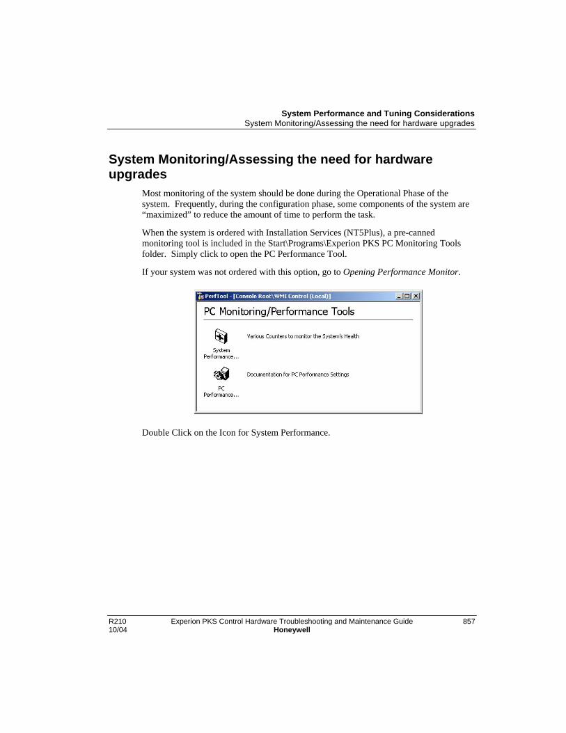
System Performance and Tuning ConsiderationsSystem Monitoring/Assessing the need for hardware upgrades
R210 Experion PKS Control Hardware Troubleshooting and Maintenance Guide 85710/04 Honeywell
System Monitoring/Assessing the need for hardwareupgrades
Most monitoring of the system should be done during the Operational Phase of thesystem. Frequently, during the configuration phase, some components of the system are“maximized” to reduce the amount of time to perform the task.
When the system is ordered with Installation Services (NT5Plus), a pre-cannedmonitoring tool is included in the Start\Programs\Experion PKS PC Monitoring Toolsfolder. Simply click to open the PC Performance Tool.
If your system was not ordered with this option, go to Opening Performance Monitor.
Double Click on the Icon for System Performance.

System Performance and Tuning ConsiderationsSystem Monitoring/Assessing the need for hardware upgrades
858 Experion PKS Control Hardware Troubleshooting and Maintenance Guide R210Honeywell 10/04
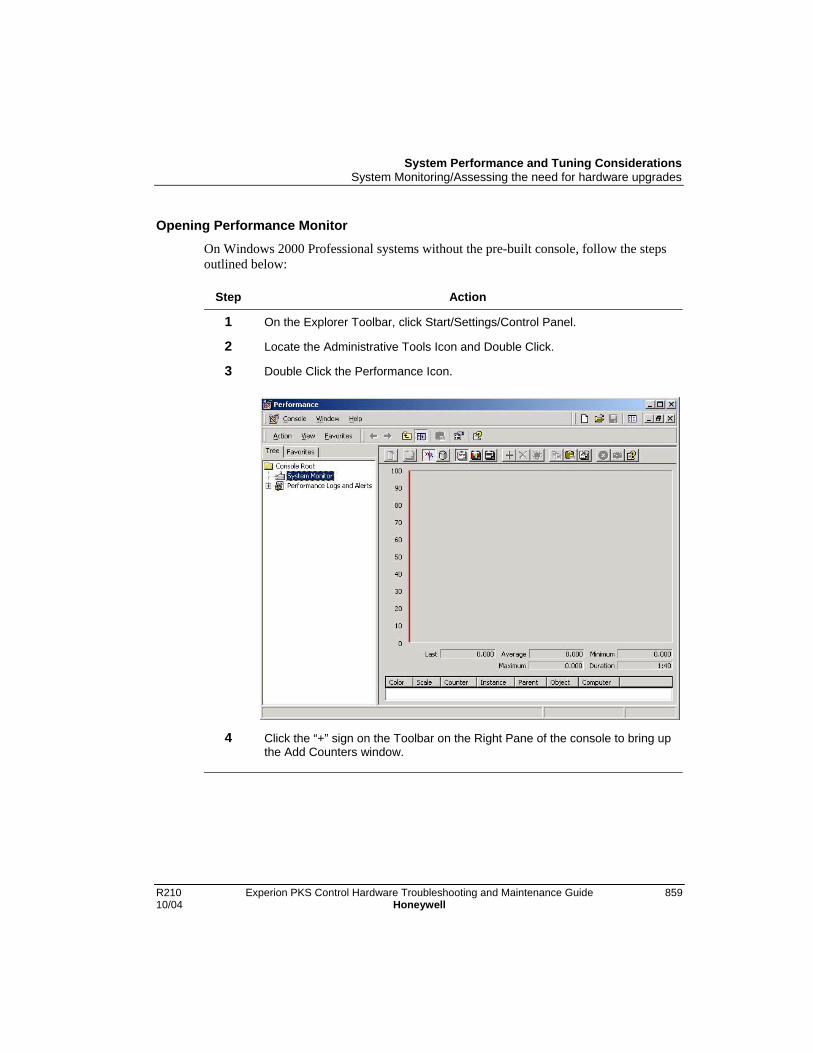
System Performance and Tuning ConsiderationsSystem Monitoring/Assessing the need for hardware upgrades
R210 Experion PKS Control Hardware Troubleshooting and Maintenance Guide 85910/04 Honeywell
Opening Performance Monitor
On Windows 2000 Professional systems without the pre-built console, follow the stepsoutlined below:
Step Action
1 On the Explorer Toolbar, click Start/Settings/Control Panel.
2 Locate the Administrative Tools Icon and Double Click.
3 Double Click the Performance Icon.
4 Click the “+” sign on the Toolbar on the Right Pane of the console to bring upthe Add Counters window.

System Performance and Tuning ConsiderationsSystem Monitoring/Assessing the need for hardware upgrades
860 Experion PKS Control Hardware Troubleshooting and Maintenance Guide R210Honeywell 10/04
Step Action
Add the Following Counters:
RefNumber
PerformanceObject
Counter Instance
1 Paging File % Usage \\??\C:\Pagefile.sys
2 System Processor QueueLength
3 System ContextSwitches/Sec
4 Processor % Processor Time _Total
5 Processor % Interrupt Time _Total
6 Server WorkQueues
Queue Length 0
7 Server WorkQueues
BytesTransferred/Sec
0
5
8 TCP Segments/Sec
System Performance and Tuning ConsiderationsSystem Monitoring/Assessing the need for hardware upgrades
R210 Experion PKS Control Hardware Troubleshooting and Maintenance Guide 86110/04 Honeywell
Interpreting the Performance Counter Values:
Paging File Usage
(Reference Number 1.)
Evaluating the Paging File Usage counter will tell you whether or not your system hasenough physical RAM. The counter itself tells you how often the system is using thePaging File. Average values approaching 40% or higher are a strong indication that thesystem is running without enough memory.
Recommendation: Add more Physical RAM.
Processor Speed and quantity
In order to evaluate whether or not your system has adequate processing power, you mustlook a several counters:
• System/Processor Queue Length
• System/Context Switches/Sec
• Processor/% Processor Time
• Processor/% Interrupt Time
• Server Work Queues/Queue Length
(Reference Numbers 2-6)
The Processor Queue Length indicates how many threads are waiting for CPU time.Evaluating the Average will give you an idea of how well the system is supporting theconfiguration. Generally, numbers averaging from 2 to 15 indicate the system couldreceive a benefit by moving to a faster CPU. Numbers averaging above 15 indicate thesystem could receive a benefit by moving to a Multiple CPU system. (Microsoft statesthat systems with average queue lengths above 2 indicate processor congestion.)
Evaluating the Context Switches/Sec will give you an idea of how busy the system is.The counter measures the number of times a thread voluntarily relinquishes theprocessor, is preempted by a higher priority ready thread, or switches between user-modeand privileged (kernel) mode to use an Executive or subsystem service.
The Percent Processor Time indicates the utilization of the processor measured in apercentage. Average percentages higher than 50% usually indicate that the system couldbenefit from an upgrade to a faster processor or multiple CPU system.

System Performance and Tuning ConsiderationsSystem Monitoring/Assessing the need for hardware upgrades
862 Experion PKS Control Hardware Troubleshooting and Maintenance Guide R210Honeywell 10/04
The Percent Interrupt Time indicates how often the system is handling hardwarerelated tasks. In the Process Control System, this will indicate where CPU congestionmight exist. Whether it is coming from the Control configuration or the process ofservicing clients. Evaluating this counter may assist you in customizing your systemconfiguration and usage to gain the best performance.
The Server Work Queue Length indicates the workload the server is performing. Asustained queue length greater than four might indicate processor congestion.
You should evaluate all these counters before considering an upgrade for the CPU.Faster Speed Processors will not always solve CPU performance problems. Somesystems will require the use of Multiple CPUs. If you are unsure of the CPUrequirements of your system, then you should purchase a system capable of supportingMultiple CPUs. This leaves you the option of going to higher speed CPUs as well as theability to add a second.
Networking
Network utilization is best measured using third party tools to evaluate the NetworkHardware itself. However, you can gain knowledge by how a particular Server node isperforming by looking at the following counters:
• Server Work Queues/Bytes Transferred/Sec
• TCP/Segments/Sec
With these counters, you should also evaluate the network using the pre-installednetwork diagnostic tools provided with the Network Drivers. Two exist depending onPlatform and Configuration:
3Com Diagnostic Tool: For use with 3Com Cards on thefollowing platforms: GX1, GX200,PE300/500 Note 1, and PE1400/1500Note 1.
Accessed by running Start, Programs,3Com NIC Utilities, 3Com NIC Doctor.
Intel Pro Set: For use with Intel Pro Cards on followingplatforms: PE300/500 andPE1400/1500.
Accessed by running Start, Settings,Control Panel and double clicking theIntel ® ProSet Icon.

System Performance and Tuning ConsiderationsSystem Monitoring/Assessing the need for hardware upgrades
R210 Experion PKS Control Hardware Troubleshooting and Maintenance Guide 86310/04 Honeywell
Experion PKS Clients utilize two types of methods to communicate with the Server. Toadequately evaluate the performance of this mechanism, it requires viewing bothcounters at the server to determine how busy the network/server is performing thesetasks.
The Bytes Transferred/Sec shows how busy the Server is servicing network clients.This is the rate at which the Server is sending and receiving bytes with the clients.
The TCP/Segments/Sec shows the amount of TCP traffic sent or received by the Server.
TIP
3Com cards are included if additional networking cards are specified in theconfiguration on these platforms.

System Performance and Tuning ConsiderationsSystem Monitoring/Assessing the need for hardware upgrades
864 Experion PKS Control Hardware Troubleshooting and Maintenance Guide R210Honeywell 10/04
R210 Experion PKS Control Hardware Troubleshooting and Maintenance Guide 86510/04 Honeywell
Spare Parts
CNI Parts
General Notes
ATTENTION
Upon redundant controller switchover, the CNIs within the RedundantChassis Pair (RCP) are temporarily not visible on their respective ControlNetsegments. To ensure that the network is maintained, a minimum of two otherControlNet Nodes must remain on the ControlNet segment during theswitchover operation. A method to avoid a single ControlNet node from goinglonely during RCP switchover is to add another CNI module, or anotherSeries A/H Rail Gateway module, or another Foundation Fieldbus LinkingDevice to the same ControlNet segment. This additional ControlNet device iscommonly known as a “Buddy Node”.
ATTENTION
Note that after reprogramming the Secondary CNI’s ControlNet parameters tomatch that of the Primary CNI, the Secondary CNI must be power-cycled sothat redundant partner compatibility checks are re-attempted.
TC-CCN011
Description Single Media Series A ControlNet Interface Card.
FW Location \Program Files\Honeywell\Experion PKS\EngineeringTools\System\Firmware\CNI\SeriesA\
ControllerRedundancy
Not supported. This implies that this CNI cannot be present in aRCP. However, this CNI can be used in a remote I/O chassis oras a “Buddy Node”.
CAUTION
At this time a TC-CCN011 cannot be used as a “Buddy Node” in a redundantmedia system.

Spare PartsCNI Parts
866 Experion PKS Control Hardware Troubleshooting and Maintenance Guide R210Honeywell 10/04
TC-CCR011
Description Redundant Media Series A ControlNet Interface Card.
FW Location \Program Files\Honeywell\Experion PKS\EngineeringTools\System\Firmware\CNI\SeriesA\
ControllerRedundancy
Not supported. This implies that this CNI cannot be present in aRCP. However, this CNI can be used in a remote I/O chassis oras a “Buddy Node”.
TC-CCN012
Description Single Media Series C ControlNet Interface Card.
FW Location \Program Files\Honeywell\Experion PKS\EngineeringTools\System\Firmware\CNI\SeriesC\
ControllerRedundancy
Supported.
RedundancyCompatibility
The TC-CCN012 is compatible with another TC-CCN012 that hasthe same ControlNet parameter configuration and firmwarerevision.
Furthermore, the TC-CCN012 is compatible with the TC-CCN013that has the same ControlNet parameter configuration with onelimitation: the TC-CCN012 must be in the primary redundancyrole. The intent of this design enhancement is to allow a customerto migrate to the TC-CCN013 while on process. For example, ifthe customer only has TC-CCN013 spares and a TC-CCN012fails in a RCP, the customer {1} replaces the faulted TC-CCN012in the secondary chassis with a TC-CCN013 (the RCPsynchronizes), {2} commands a switchover, and {3} replaces thegood TC-CCN012 in the secondary chassis with a TC-CCN013.Upon switchover to the primary role, the TC-CCN013 is notcompatible with the TC-CCN012 because the TC-CCN013 hasmore resources (e.g. memory) than the TC-CCN012.
Note that the ability to synchronize with a primary TC-CCN012and secondary TC-CCN013 is only available starting in c4.20 andd5.20 firmware revisions respectively.

Spare PartsCNI Parts
R210 Experion PKS Control Hardware Troubleshooting and Maintenance Guide 86710/04 Honeywell
TC-CCR012
Description Redundant Media Series C ControlNet Interface Card.
FW Location \Program Files\Honeywell\Experion PKS\EngineeringTools\System\Firmware\CNI\SeriesC\
ControllerRedundancy
Supported.
RedundancyCompatibility
The TC-CCR012 is compatible with another TC-CCR012 that hasthe same ControlNet parameter configuration and firmwarerevision.
Furthermore, the TC-CCR012 is compatible with the TC-CCR013that has the same ControlNet parameter configuration with onelimitation: the TC-CCR012 must be in the primary redundancyrole. The intent of this design enhancement is to allow a customerto migrate to the TC-CCR013 while on process. For example, ifthe customer only has TC-CCR013 spares and a TC-CCR012fails in a RCP, the customer {1} replaces the faulted TC-CCR012in the secondary chassis with a TC-CCR013 (the RCPsynchronizes), {2} commands a switchover, and {3} replaces thegood TC-CCR012 in the secondary chassis with a TC-CCR013.Upon switchover to the primary role, the TC-CCR013 is notcompatible with the TC-CCR012 because the TC-CCR013 hasmore resources (e.g. memory) than the TC-CCR012.
Note that the ability to synchronize with a primary TC-CCR012and secondary TC-CCR013 is only available starting in c4.20 andd5.20 firmware revisions respectively.
TC-CCN013
Description Single Media Series D ControlNet Interface Card.
FW Location \Program Files\Honeywell\Experion PKS\EngineeringTools\System\Firmware\CNI\SeriesD\
ControllerRedundancy
Supported.
RedundancyCompatibility
The TC-CCN013 is compatible with another TC-CCN013 that hasthe same ControlNet parameter configuration and firmwarerevision.
Spare PartsCNI Parts
868 Experion PKS Control Hardware Troubleshooting and Maintenance Guide R210Honeywell 10/04
TC-CCR013
Description Redundant Media Series D ControlNet Interface Card.
FW Location \Program Files\Honeywell\Experion PKS\EngineeringTools\System\Firmware\CNI\SeriesD\
ControllerRedundancy
Supported.
RedundancyCompatibility
The TC-CCR013 is compatible with another TC-CCR013 that hasthe same ControlNet parameter configuration and firmwarerevision.

Spare PartsPeriodic Maintenance Parts for C200 Controller
R210 Experion PKS Control Hardware Troubleshooting and Maintenance Guide 86910/04 Honeywell
Periodic Maintenance Parts for C200 Controller
Recommended replacement parts
The following tables list items that are recommended for periodic replacementmaintenance during the life of the C200 Process Controller components.
Part Description RecommendedReplacement
Interval
Model Number
Lithium Battery Control Processor Module(CPM) Battery Backup
Annually TC-BATT01
NiCad RechargeableBattery Pack
Battery Extension Module(BEM) Battery Pack
Every Two (2)Years
TC-BATT03
Periodic Maintenance Parts for PM I/O
Periodic maintenance parts list
The following tables list items that may be required for maintenance during the life of theProcess Manager I/O components.
Batteries
Name Description Part Number
AA-size NiCad battery, (quantity 1) 51190422-100NiCad RechargeableBatteries
C-size NiCad battery, (quantity 1) 51192060-100
Alkaline Batteries AA-size Alkaline battery, (quantity 1) 51190467-100
Replacement Fuses
For Assembly…(Assembly No.)
Fuse Description Qty Part Number
Left 7-Slot Card File(51401626)
2.0 A Subminiature fuse (F1-8) 8 30754661-021
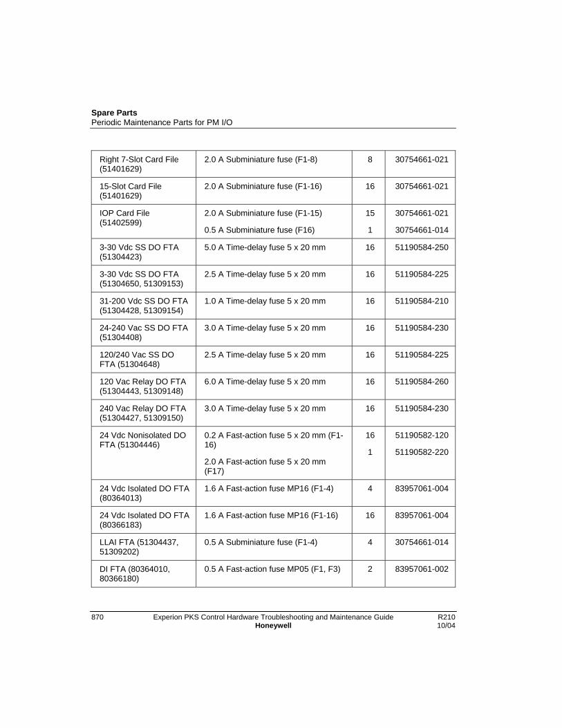
Spare PartsPeriodic Maintenance Parts for PM I/O
870 Experion PKS Control Hardware Troubleshooting and Maintenance Guide R210Honeywell 10/04
Right 7-Slot Card File(51401629)
2.0 A Subminiature fuse (F1-8) 8 30754661-021
15-Slot Card File(51401629)
2.0 A Subminiature fuse (F1-16) 16 30754661-021
IOP Card File(51402599)
2.0 A Subminiature fuse (F1-15)
0.5 A Subminiature fuse (F16)
15
1
30754661-021
30754661-014
3-30 Vdc SS DO FTA(51304423)
5.0 A Time-delay fuse 5 x 20 mm 16 51190584-250
3-30 Vdc SS DO FTA(51304650, 51309153)
2.5 A Time-delay fuse 5 x 20 mm 16 51190584-225
31-200 Vdc SS DO FTA(51304428, 51309154)
1.0 A Time-delay fuse 5 x 20 mm 16 51190584-210
24-240 Vac SS DO FTA(51304408)
3.0 A Time-delay fuse 5 x 20 mm 16 51190584-230
120/240 Vac SS DOFTA (51304648)
2.5 A Time-delay fuse 5 x 20 mm 16 51190584-225
120 Vac Relay DO FTA(51304443, 51309148)
6.0 A Time-delay fuse 5 x 20 mm 16 51190584-260
240 Vac Relay DO FTA(51304427, 51309150)
3.0 A Time-delay fuse 5 x 20 mm 16 51190584-230
24 Vdc Nonisolated DOFTA (51304446)
0.2 A Fast-action fuse 5 x 20 mm (F1-16)
2.0 A Fast-action fuse 5 x 20 mm(F17)
16
1
51190582-120
51190582-220
24 Vdc Isolated DO FTA(80364013)
1.6 A Fast-action fuse MP16 (F1-4) 4 83957061-004
24 Vdc Isolated DO FTA(80366183)
1.6 A Fast-action fuse MP16 (F1-16) 16 83957061-004
LLAI FTA (51304437,51309202)
0.5 A Subminiature fuse (F1-4) 4 30754661-014
DI FTA (80364010,80366180)
0.5 A Fast-action fuse MP05 (F1, F3) 2 83957061-002

Spare PartsPeriodic Maintenance Parts for PM I/O
R210 Experion PKS Control Hardware Troubleshooting and Maintenance Guide 87110/04 Honeywell
DI FTA (80364010,80366180)
1.0 A Fast-action fuse MP10 (F2) 1 83957061-003
DI Power DistributionAssy (51304425)
1.0 A Fast-action fuse 5 x 20 mm (F1-12)
12 51190582-210
Nonredundant AO FTA(51304476)
1.0 A Fast-action fuse 5 x 20 mm (F1-12)
12 51190582-210
Redundant AO FTA(51304335)
1.0 A Fast-action fuse 5 x 20 mm (F1-3)
3 51190582-210
Redundant AO FTA(80364007, 80366177,80366481, 80366484)
1.0 A Fast-action fuse MP10 (F1) 1 83957061-003
Pulse Input FTA(51304084)
0.25 A Fast-action fuse 5 x 20 mm(F1-8)
8 51190582-125
Galvanic AO FTA(51304638)
1.0 A Subminiature fuse (F1-3) 3 30754661-019
GI Power DistributionAssy (51304644)
4.0 A Fast-action fuse 5 x 20 mm (F1-8)
8 51190582-240
I/O Link Card 3.0 A Fast-action fuse (F1) 1 30754661-022
Fuseholder Puller Fuseholder extractor 51190586-100
Filters
Name Description Part Number
Filter Kit (Rittal cabinet) Louvered cover and filter, 20 /8 x 20 /8(cm/in.)
51109488-100
Filter (Rittal cabinet) Replacement filter only, 20 /8 x 20 /8(cm/in.)
51109488-200
Filter (Markhon cabinet) Replacement filter only, 39 /15.5 x 61 /24(cm/in.)
51109541-100
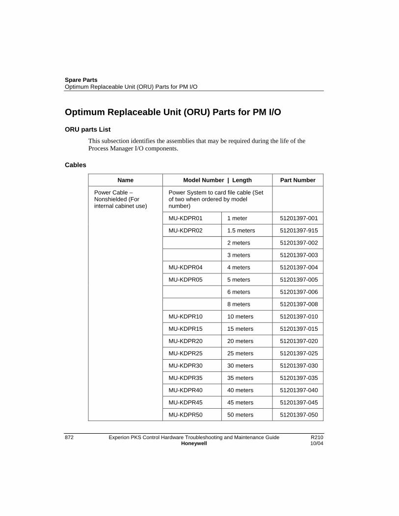
Spare PartsOptimum Replaceable Unit (ORU) Parts for PM I/O
872 Experion PKS Control Hardware Troubleshooting and Maintenance Guide R210Honeywell 10/04
Optimum Replaceable Unit (ORU) Parts for PM I/O
ORU parts List
This subsection identifies the assemblies that may be required during the life of theProcess Manager I/O components.
Cables
Name Model Number | Length Part Number
Power System to card file cable (Setof two when ordered by modelnumber)
MU-KDPR01 1 meter 51201397-001
MU-KDPR02 1.5 meters 51201397-915
2 meters 51201397-002
3 meters 51201397-003
MU-KDPR04 4 meters 51201397-004
MU-KDPR05 5 meters 51201397-005
6 meters 51201397-006
8 meters 51201397-008
MU-KDPR10 10 meters 51201397-010
MU-KDPR15 15 meters 51201397-015
MU-KDPR20 20 meters 51201397-020
MU-KDPR25 25 meters 51201397-025
MU-KDPR30 30 meters 51201397-030
MU-KDPR35 35 meters 51201397-035
MU-KDPR40 40 meters 51201397-040
MU-KDPR45 45 meters 51201397-045
Power Cable –Nonshielded (Forinternal cabinet use)
MU-KDPR50 50 meters 51201397-050

Spare PartsOptimum Replaceable Unit (ORU) Parts for PM I/O
R210 Experion PKS Control Hardware Troubleshooting and Maintenance Guide 87310/04 Honeywell
Name Model Number | Length Part Number
Power System to card file cable – Setof two (With surge protection networkfor I/O Link cable)
1.0 meter 51204126-001
1.5 meters 51204126-915
2 meters 51204126-002
3 meters 51204126-003
4 meters 51204126-004
5 meters 51204126-005
Power Cable –Nonshielded (internalcabinet use)
6 meters 51204126-006
Power Cable AdapterCable –Nonshield(internal cabinet use)
Power cable I/O Link protectoradapter – Set of two (Provides I/OLink protector for 51201397-xxx cable)
51204127-100
Combination power and I/O linkinterface cable used to connect theI/O Link Interface Module to the IOPcard file and the IOP power system(The cable includes leads forconnecting 24 Vdc power to theProcess Controller chassis powersupply.)
TC-KIOL02 2 meters 51202306-100
TC-KIOL05 5 meters 51202306-200
Power and I/O LinkInterface Cable
TC-KIOL10 10 meters 51202306-300

Spare PartsOptimum Replaceable Unit (ORU) Parts for PM I/O
874 Experion PKS Control Hardware Troubleshooting and Maintenance Guide R210Honeywell 10/04
Name Model Number | Length Part Number
Power System to Power DistributionAssembly cable (Set of two whenordered by model number)
MU-KSPR05 5 meters 51204037-005
MU-KSPR10 10 meters 51204037-010
MU-KSPR15 15 meters 51204037-015
MU-KSPR20 20 meters 51204037-020
MU-KSPR25 25 meters
MU-KSPR30 30 meters 51204037-030
MU-KSPR35 35 meters
MU-KSPR40 40 meters 51204037-040
Power Cable – Shielded(For external cabinetuse)
MU-KSPR50 50 meters 51204037-050
Power System to card file cable – Setof two (With surge protection networkfor I/O Link cable)
1.0 meter 51204138-001
1.5 meters 51204138-915
2 meters 51204138-002
3 meters 51204138-003
4 meters 51204138-004
5 meters 51204138-005
Power Cable – Shielded(For external cabinetuse)
6 meters 51204138-006

Spare PartsOptimum Replaceable Unit (ORU) Parts for PM I/O
R210 Experion PKS Control Hardware Troubleshooting and Maintenance Guide 87510/04 Honeywell
Name Model Number | Length Part Number
Power cable I/O Link protectoradapter – Set of two (Provides I/OLink protector for 51204037-xxx cable)GI Power Distribution assembly toFTA cable
51204140-100
0.50 meter 51109620-020
0.75 meter 51109620-030
1.00 meter 51109620-040
1.25 meters 51109620-050
2 meters 51109620-080
3 meters 51109620-120
4 meters 51109620-160
MU-KGPR05 5 meters 51109620-195
Galv Isolation FTAPower Cable (Forinternal cabinet use)
MU-KGPR10 10 meters 51109620-390
Bridge cable for model MU/MC-TDOY23 and MU/MC-TDOY63 FTAs
1 meter 80366198-100
Bridge Cable
2 meters 80366198-200

Spare PartsOptimum Replaceable Unit (ORU) Parts for PM I/O
876 Experion PKS Control Hardware Troubleshooting and Maintenance Guide R210Honeywell 10/04
Name Model Number | Length Part Number
Power Adapter to LLMux/SDI/SI FTAcable (External to the cabinet forLLMux/SDI/SI)
Special order 51190696-xxx
76 meters 51190696-076
152 meters 51190696-152
Power Adapter Cable(Non-CE ComplyApplications)
305 meters 51190696-305
Power Adapter toLLMux/RHMUX/SDI/SI FTA cable(External to the cabinet forLLMux/SDI/SI) (Internal to the cabinetfor RHMUX)
Special order 51192139-104
MU-KLX076 76 meters 51192139-114
MU-KLX152 152 meters 51192139-124
Power Adapter Cable(CE CompliantApplications)
MU-KLX305 305 meters 51192139-134
RHMUX Power Adapter to RHMUXFTA cable (External to the cabinet)
Special order 51197597-100
RHMUX Power AdapterCable (CE CompliantApplications)
MU-KLO305 305 meters 51197597-305
Power Adapter to LLMux/SDI/SI FTAcable (Internal to the cabinet)
MU-KLAM01 30 centimeters 51304465-100
MU-KLAM02 66 centimeters 51304465-200
MU-KLAM03 100 centimeters 51304465-300
MU-KLAM06 200 centimeters 51304465-400
Power Adapter Cable(Non-CE ComplyApplications)
MU-KLAM09 300 centimeters 51304465-500
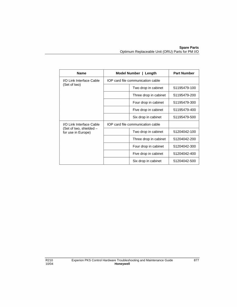
Spare PartsOptimum Replaceable Unit (ORU) Parts for PM I/O
R210 Experion PKS Control Hardware Troubleshooting and Maintenance Guide 87710/04 Honeywell
Name Model Number | Length Part Number
IOP card file communication cable
Two drop in cabinet 51195479-100
Three drop in cabinet 51195479-200
Four drop in cabinet 51195479-300
Five drop in cabinet 51195479-400
I/O Link Interface Cable(Set of two)
Six drop in cabinet 51195479-500
IOP card file communication cable
Two drop in cabinet 51204042-100
Three drop in cabinet 51204042-200
Four drop in cabinet 51204042-300
Five drop in cabinet 51204042-400
I/O Link Interface Cable(Set of two, shielded –for use in Europe)
Six drop in cabinet 51204042-500

Spare PartsOptimum Replaceable Unit (ORU) Parts for PM I/O
878 Experion PKS Control Hardware Troubleshooting and Maintenance Guide R210Honeywell 10/04
Name Model Number | Length Part Number
IOP to FTA cable
1 meter 51201420-001
1.5 meters 51201420-915
MU-KFTA02 2 meters 51201420-002
MU-KFTA03 3 meters 51201420-003
MU-KFTA04 4 meters 51201420-004
MU-KFTA05 5 meters 51201420-005
6 meters 51201420-006
MU-KFTA08 8 meters 51201420-008
MU-KFTA10 10 meters 51201420-010
MU-KFTA15 10 meters 51201420-015
MU-KFTA20 20 meters 51201420-020
MU-KFTA25 25 meters 51201420-025
MU-KFTA30 30 meters 51201420-030
MU-KFTA35 35 meters 51201420-035
MU-KFTA40 40 meters 51201420-040
MU-KFTA45 45 meters 51201420-045
IOP to FTACable
MU-KFTA50 50 meters 51201420-050

Spare PartsOptimum Replaceable Unit (ORU) Parts for PM I/O
R210 Experion PKS Control Hardware Troubleshooting and Maintenance Guide 87910/04 Honeywell
Name Model Number | Length Part Number
IOP to FTA cable
1 meter 51204033-001
1.5 meters 51204033-915
MU-KFTS02 2 meters 51204033-002
MU-KFTS03 3 meters 51204033-003
MU-KFTS04 4 meters 51204033-004
MU-KFTS05 5 meters 51204033-005
6 meters 51204033-006
MU-KFTS08 8 meters 51204033-008
MU-KFTS10 10 meters 51204033-010
MU-KFTS15 15 meters 51204033-015
MU-KFTS20 20 meters 51204033-020
MU-KFTS25 25 meters 51204033-025
MU-KFTS30 30 meters 51204033-030
MU-KFTS35 35 meters 51204033-035
MU-KFTS40 40 meters 51204033-040
MU-KFTS45 45 meters 51204033-045
IOP to FTACable (Shielded– for externalcabinet use)
MU-KFTS50 50 meters 51204033-050

Spare PartsOptimum Replaceable Unit (ORU) Parts for PM I/O
880 Experion PKS Control Hardware Troubleshooting and Maintenance Guide R210Honeywell 10/04
Power system components - non-conformally coated
Name Description Part Number
Power Supply Module Standard 20 A Power Supply Module 51109456-200
Power Supply Module AC Only 8 A Power Supply Module 51190465-100
Power Supply Module AC Only 16 A Power Supply Module 51190465-200
48 V Battery Backup 48 V Battery Pack assembly 51303948-100
AC/DC DistributionAssembly
AC Only power control and distributionboard 115 Vac dual PSMs
51401135-100
AC/DC DistributionAssembly
AC Only power control and distributionboard 115 Vac single PSM
51401135-200
AC/DC DistributionAssembly
AC Only power control and distributionboard 230 Vac dual PSMs
51401135-300
AC/DC DistributionAssembly
AC Only power control and distributionboard 230 Vac single PSM
51401135-400
CMOS Battery BackupAssembly
PS Charger/monitor for CMOSmemory
51309206-100
Power SystemBackpanel Assy
Power System backpanel 51404172-100

Spare PartsOptimum Replaceable Unit (ORU) Parts for PM I/O
R210 Experion PKS Control Hardware Troubleshooting and Maintenance Guide 88110/04 Honeywell
Power system components - conformally coated
Name Description Part Number
Power Supply Module Standard 20 A Power SupplyModule
51109456-200
Power Supply Module AC Only 8 A Power SupplyModule
51190465-150
Power Supply Module AC Only 16 A Power SupplyModule
51190465-250
48 V Battery Backup 48 V Battery Pack assembly 51303948-100
AC/DC DistributionAssembly
AC Only power control anddistribution board 115 Vac dualPSMs
51401135-150
AC/DC DistributionAssembly
AC Only power control anddistribution board 115 Vac singlePSM
51401135-250
AC/DC DistributionAssembly
AC Only power control anddistribution board 230 Vac dualPSMs
51401135-350
AC/DC DistributionAssembly
AC Only power control anddistribution board 230 Vac singlePSM
51401135-450
CMOS Battery BackupAssembly
PS Charger/monitor for CMOSmemory
51309206-150
Power SystemBackpanel Assy
Power System backpanel 51404172-150

Spare PartsOptimum Replaceable Unit (ORU) Parts for PM I/O
882 Experion PKS Control Hardware Troubleshooting and Maintenance Guide R210Honeywell 10/04
IOP cards - non-conformally coated
Name (Model No.) Description Part Number
HLAI IOP (MU-PAIH02) High Level Analog Input card(Replaced by 51304754-100)
51304489-100
HLAI IOP (MU-PAIH03) High Level Analog Input card 51304754-100
LLAI IOP (MU-PAIL02) Low Level Analog Input card 51304481-100
LLMux IOP (MU-PLAM02)
Low Level Multiplexer card 51304362-100
RHMUX(MU-PRHM01) Remote Hardened Low LevelMultiplexer card
51404109-125
DI IOP (MU-PDIX02) Digital Input card 51304485-100
DI IOP (MU-PDIY22) Digital Input card 80363972-100
AO IOP (MU-PAOX02) Analog Output 51304483-100
AO IOP (MU-PAOX03) Analog Output card (Replaced by51309152-175)
51304672-100
AO IOP (MU-PAOX03) Analog Output card (ConformallyCoated)
51309152-175
AO IOP (MU-PAOY22) Analog Output card 80363969-100
DO IOP (MU-PDOX02) Digital Output card 51304487-100
DO IOP (MU-PDOY22) Digital Output card 80363975-100
STI IOP (MU-PSTX02) Smart Transmitter Interface card(Replaced by 51304516-200)
51304516-100
STI_MV (MU-PSTX03) Smart Transmitter InterfaceMultivariable
51304516-200
DISOE IOP (MU-PDIS11)
Digital Input Sequence Of Eventscard (Replaced by 51402625-125)
51304690-100
DISOE IOP (MU-PDIS12)
Digital Input Sequence Of Eventscard
51402625-125
Slot Filler Empty IOP slot filler card 51304260-200

Spare PartsOptimum Replaceable Unit (ORU) Parts for PM I/O
R210 Experion PKS Control Hardware Troubleshooting and Maintenance Guide 88310/04 Honeywell
IOP cards - conformally coated
Name (Model No.) Description Part Number
HLAI IOP (MC-PAIH02) High Level Analog Input card 51304489-150
HLAI IOP (MC-PAIH03) High Level Analog Input card 51304754-150
HLAIHART (MC-PHAI01) HART Analog Input card 51403479-150
LLAI IOP (MC-PAIL02) Low Level Analog Input card 51304481-150
LLMux IOP (MC-PLAM02)
Low Level Multiplexer card 51304362-150
RHMUX (MC-PRHM01) Remote Hardened Low LevelMultiplexer card
51404109-175
DI IOP (MC-PDIX02) Digital Input card 51304485-150
DI IOP (MC-PDIY22) Digital Input card 80363972-150
AO IOP (MC-PAOX02) Analog Output 51304483-150
AO IOP (MC-PAOX03) Analog Output card (Replaced by51309152-175)
51304672-150
AO IOP (MC-PAOX03) Analog Output card 51309152-175
AO IOP (MC-PAOY22) Analog Output card 80363969-150
AO16HART (MC-PHAO01)
HART 16-Channel Analog Outputcard
51403476-150
DO IOP (MC-PDOX02) Digital Output card 51304487-150
DO IOP (MC-PDOY22) Digital Output card 80363975-150
STI IOP (MC-PSTX02) Smart Transmitter Interface card(Replaced by 51304516-200)
51304516-150
STI_MV IOP (MC-PSTX03)
Smart Transmitter InterfaceMultivariable
51304516-250
DISOE IOP (MC-PDIS11)
Digital Input Sequence Of Eventscard (Replaced by 51402625-125)
51304690-150
DISOE IOP (MC-PDIS12)
Digital Input Sequence Of Eventscard
51402625-175
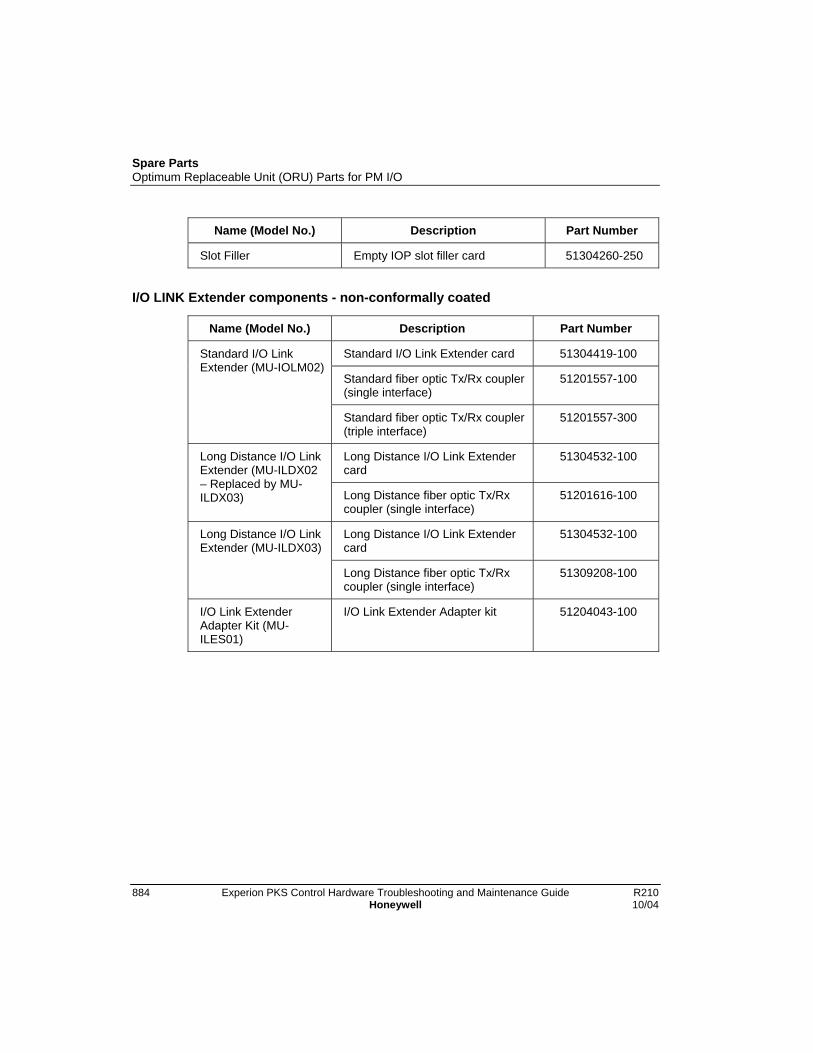
Spare PartsOptimum Replaceable Unit (ORU) Parts for PM I/O
884 Experion PKS Control Hardware Troubleshooting and Maintenance Guide R210Honeywell 10/04
Name (Model No.) Description Part Number
Slot Filler Empty IOP slot filler card 51304260-250
I/O LINK Extender components - non-conformally coated
Name (Model No.) Description Part Number
Standard I/O Link Extender card 51304419-100
Standard fiber optic Tx/Rx coupler(single interface)
51201557-100
Standard I/O LinkExtender (MU-IOLM02)
Standard fiber optic Tx/Rx coupler(triple interface)
51201557-300
Long Distance I/O Link Extendercard
51304532-100Long Distance I/O LinkExtender (MU-ILDX02– Replaced by MU-ILDX03) Long Distance fiber optic Tx/Rx
coupler (single interface)51201616-100
Long Distance I/O Link Extendercard
51304532-100Long Distance I/O LinkExtender (MU-ILDX03)
Long Distance fiber optic Tx/Rxcoupler (single interface)
51309208-100
I/O Link ExtenderAdapter Kit (MU-ILES01)
I/O Link Extender Adapter kit 51204043-100

Spare PartsOptimum Replaceable Unit (ORU) Parts for PM I/O
R210 Experion PKS Control Hardware Troubleshooting and Maintenance Guide 88510/04 Honeywell
I/O LINK Extender components - conformally coated
Name (Model No.) Description Part Number
Standard I/O Link Extender card 51304419-150
Standard fiber optic Tx/Rx coupler(single interface)
51201557-150
Standard I/O LinkExtender (MC-IOLM02)
Standard fiber optic Tx/Rx coupler(triple interface)
51201557-350
Long Distance I/O Link Extendercard
51304532-150Long Distance I/O LinkExtender (MC-ILDX02– Replaced by MC-ILDX03) Long Distance fiber optic Tx/Rx
coupler (single interface)51201616-150
Long Distance I/O Link Extendercard
51304532-150Long Distance I/O LinkExtender (MC-ILDX03)
Long Distance fiber optic Tx/Rxcoupler (single interface)
51309208-150
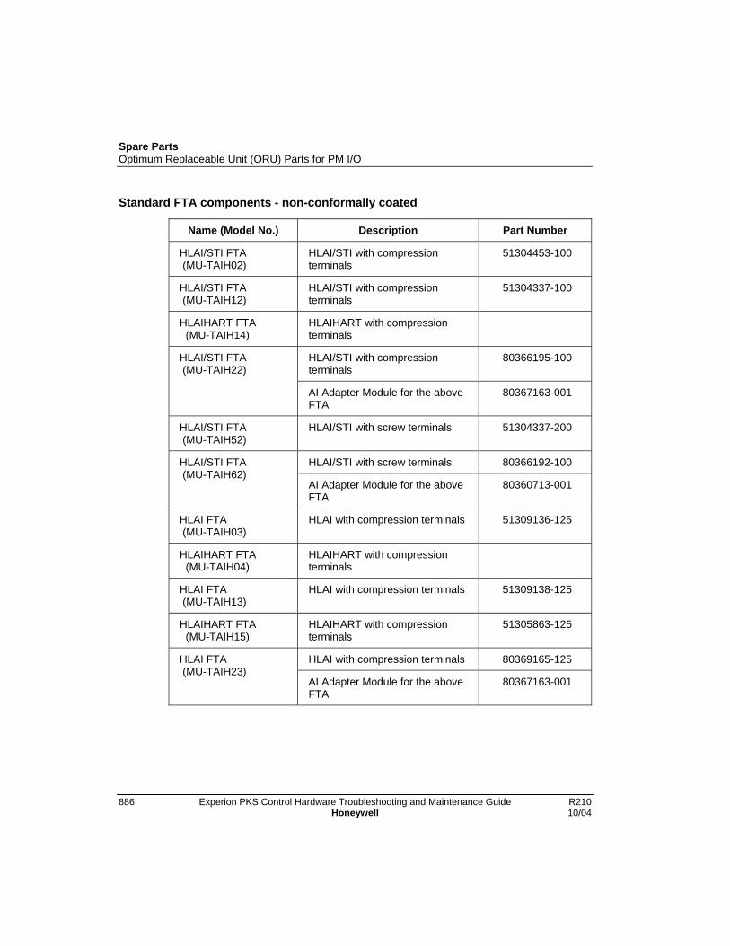
Spare PartsOptimum Replaceable Unit (ORU) Parts for PM I/O
886 Experion PKS Control Hardware Troubleshooting and Maintenance Guide R210Honeywell 10/04
Standard FTA components - non-conformally coated
Name (Model No.) Description Part Number
HLAI/STI FTA (MU-TAIH02)
HLAI/STI with compressionterminals
51304453-100
HLAI/STI FTA (MU-TAIH12)
HLAI/STI with compressionterminals
51304337-100
HLAIHART FTA (MU-TAIH14)
HLAIHART with compressionterminals
HLAI/STI with compressionterminals
80366195-100HLAI/STI FTA (MU-TAIH22)
AI Adapter Module for the aboveFTA
80367163-001
HLAI/STI FTA (MU-TAIH52)
HLAI/STI with screw terminals 51304337-200
HLAI/STI with screw terminals 80366192-100HLAI/STI FTA (MU-TAIH62)
AI Adapter Module for the aboveFTA
80360713-001
HLAI FTA (MU-TAIH03)
HLAI with compression terminals 51309136-125
HLAIHART FTA (MU-TAIH04)
HLAIHART with compressionterminals
HLAI FTA (MU-TAIH13)
HLAI with compression terminals 51309138-125
HLAIHART FTA (MU-TAIH15)
HLAIHART with compressionterminals
51305863-125
HLAI with compression terminals 80369165-125HLAI FTA (MU-TAIH23)
AI Adapter Module for the aboveFTA
80367163-001

Spare PartsOptimum Replaceable Unit (ORU) Parts for PM I/O
R210 Experion PKS Control Hardware Troubleshooting and Maintenance Guide 88710/04 Honeywell
Name (Model No.) Description Part Number
HLAI FTA (MU-TAIH53)
HLAI with screw terminals 51309138-225
HLAIHART FTA (MU-TAIH54)
HLAIHART with screw terminals 51305863-225
STI FTA (MU-TSTX03) STI with compression terminals 51309140-125
STI FTA (MU-TSTX13) STI with compression terminals 51309142-125
STI FTA (MU-TSTX53) STI with screw terminals 51309142-225
LLAI FTA with compressionterminals (Replaced by MU-TAIL03)
51304437-100LLAI FTA (MU-TAIL02)
Daughter module for above FTA(Replaced by 51309280-100)
51304085-100
LLAI FTA with compressionterminals
51309202-125LLAI FTA (MU-TAIL03)
Daughter module for above FTA 51309280-100
LLMux local TC with compressionterminals (Replaced by MU-TAMT03)
51401491-100LLMux FTA (MU-TAMT02)
LLMux Analog board for aboveFTA
51401564-100
LLMux FTA (MU-TAMT03)
LLMux local TC with compressionterminals
51409223-125
LLMux remote TC withcompression terminals (Replacedby MU-TAMT13)
51401573-100
LLMux Analog board for aboveFTA
51401564-100
LLMux FTA (MU-TAMT12)
LLMux remote sensor board forabove FTA
51304589-100
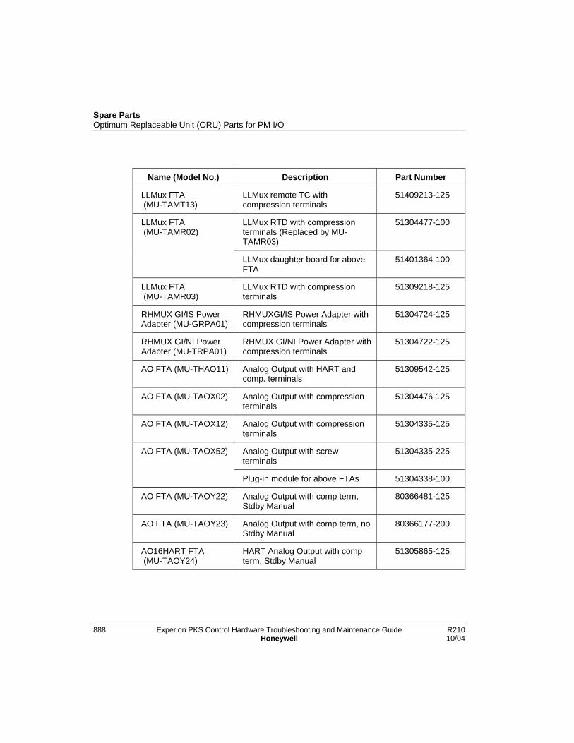
Spare PartsOptimum Replaceable Unit (ORU) Parts for PM I/O
888 Experion PKS Control Hardware Troubleshooting and Maintenance Guide R210Honeywell 10/04
Name (Model No.) Description Part Number
LLMux FTA (MU-TAMT13)
LLMux remote TC withcompression terminals
51409213-125
LLMux RTD with compressionterminals (Replaced by MU-TAMR03)
51304477-100LLMux FTA (MU-TAMR02)
LLMux daughter board for aboveFTA
51401364-100
LLMux FTA (MU-TAMR03)
LLMux RTD with compressionterminals
51309218-125
RHMUX GI/IS PowerAdapter (MU-GRPA01)
RHMUXGI/IS Power Adapter withcompression terminals
51304724-125
RHMUX GI/NI PowerAdapter (MU-TRPA01)
RHMUX GI/NI Power Adapter withcompression terminals
51304722-125
AO FTA (MU-THAO11) Analog Output with HART andcomp. terminals
51309542-125
AO FTA (MU-TAOX02) Analog Output with compressionterminals
51304476-125
AO FTA (MU-TAOX12) Analog Output with compressionterminals
51304335-125
Analog Output with screwterminals
51304335-225AO FTA (MU-TAOX52)
Plug-in module for above FTAs 51304338-100
AO FTA (MU-TAOY22) Analog Output with comp term,Stdby Manual
80366481-125
AO FTA (MU-TAOY23) Analog Output with comp term, noStdby Manual
80366177-200
AO16HART FTA (MU-TAOY24)
HART Analog Output with compterm, Stdby Manual
51305865-125
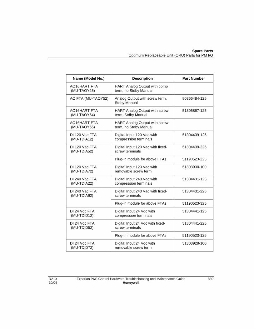
Spare PartsOptimum Replaceable Unit (ORU) Parts for PM I/O
R210 Experion PKS Control Hardware Troubleshooting and Maintenance Guide 88910/04 Honeywell
Name (Model No.) Description Part Number
AO16HART FTA (MU-TAOY25)
HART Analog Output with compterm, no Stdby Manual
AO FTA (MU-TAOY52) Analog Output with screw term,Stdby Manual
80366484-125
AO16HART FTA (MU-TAOY54)
HART Analog Output with screwterm, Stdby Manual
51305867-125
AO16HART FTA (MU-TAOY55)
HART Analog Output with screwterm, no Stdby Manual
DI 120 Vac FTA (MU-TDIA12)
Digital Input 120 Vac withcompression terminals
51304439-125
Digital Input 120 Vac with fixed-screw terminals
51304439-225DI 120 Vac FTA (MU-TDIA52)
Plug-in module for above FTAs 51190523-225
DI 120 Vac FTA (MU-TDIA72)
Digital Input 120 Vac withremovable screw term
51303930-100
DI 240 Vac FTA (MU-TDIA22)
Digital Input 240 Vac withcompression terminals
51304431-125
Digital Input 240 Vac with fixed-screw terminals
51304431-225DI 240 Vac FTA (MU-TDIA62)
Plug-in module for above FTAs 51190523-325
DI 24 Vdc FTA (MU-TDID12)
Digital Input 24 Vdc withcompression terminals
51304441-125
Digital Input 24 Vdc with fixed-screw terminals
51304441-225DI 24 Vdc FTA (MU-TDID52)
Plug-in module for above FTAs 51190523-125
DI 24 Vdc FTA (MU-TDID72)
Digital Input 24 Vdc withremovable screw term
51303928-100

Spare PartsOptimum Replaceable Unit (ORU) Parts for PM I/O
890 Experion PKS Control Hardware Troubleshooting and Maintenance Guide R210Honeywell 10/04
Name (Model No.) Description Part Number
DI 24 Vdc FTA (MU-TDIY22)
Digital Input 24 Vdc withcompression terminals
80366180-125
DI 24 Vdc FTA (MU-TDIY62)
Digital Input 24 Vdc with screwterminals
80364010-125
DO 120/240 Vac FTA (MU-TDOA12)
Digital Output 120/240 Vac SSwith fixed-comp term (Replacedby MU-TDOA13)
51304408-100
Digital Output 120/240 Vac SSwith fixed-screw term (Replacedby MU-TDOA53)
51304408-200DO 120/240 Vac FTA (MU-TDOA52)
Solid-state relay plug-in modulefor above FTAs
51190516-325
DO 120/240 Vac FTA (MU-TDOA13)
Digital Output 24-240 Vac SS withremovable compression terminals.
51304648-125
Digital Output 24-240 Vac SS withremovable screw terminals
51304648-225DO 120/240 Vac FTA (MU-TDOA53)
Solid-state relay plug-in modulefor above FTAs
51190516-332
DO 3-30 Vdc FTA (MU-TDOD12)
Digital Output 3-30 Vdc SS withfixed-comp term (Replaced byMU-TDOD13)
51304423-100
Digital Output 3-30 Vdc SS withfixed-screw term (Replaced byMU-TDOD53)
51304423-200DO 3-30 Vdc FTA (MU-TDOD52)
Solid-state relay plug-in modulefor above FTAs
51190516-122
DO 3-30 Vdc FTA (MU-TDOD13)
Digital Output 3-30 Vdc SS withremovable compression terminals
51304650-100
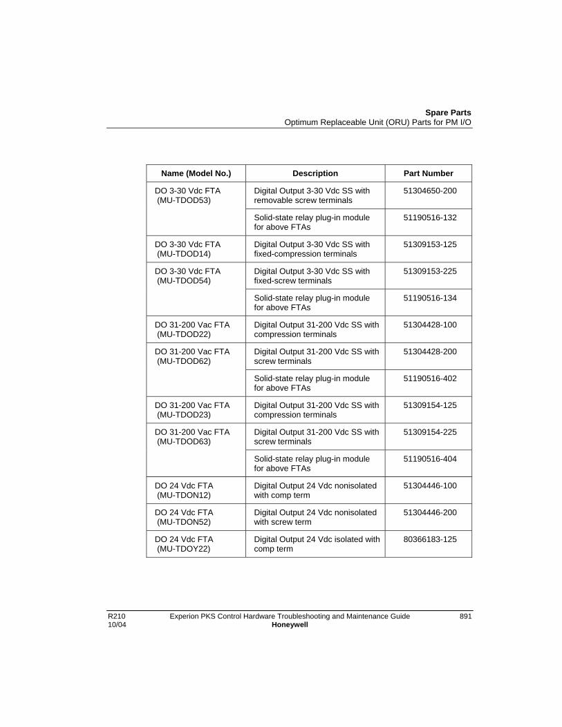
Spare PartsOptimum Replaceable Unit (ORU) Parts for PM I/O
R210 Experion PKS Control Hardware Troubleshooting and Maintenance Guide 89110/04 Honeywell
Name (Model No.) Description Part Number
Digital Output 3-30 Vdc SS withremovable screw terminals
51304650-200DO 3-30 Vdc FTA (MU-TDOD53)
Solid-state relay plug-in modulefor above FTAs
51190516-132
DO 3-30 Vdc FTA (MU-TDOD14)
Digital Output 3-30 Vdc SS withfixed-compression terminals
51309153-125
Digital Output 3-30 Vdc SS withfixed-screw terminals
51309153-225DO 3-30 Vdc FTA (MU-TDOD54)
Solid-state relay plug-in modulefor above FTAs
51190516-134
DO 31-200 Vac FTA (MU-TDOD22)
Digital Output 31-200 Vdc SS withcompression terminals
51304428-100
Digital Output 31-200 Vdc SS withscrew terminals
51304428-200DO 31-200 Vac FTA (MU-TDOD62)
Solid-state relay plug-in modulefor above FTAs
51190516-402
DO 31-200 Vac FTA (MU-TDOD23)
Digital Output 31-200 Vdc SS withcompression terminals
51309154-125
Digital Output 31-200 Vdc SS withscrew terminals
51309154-225DO 31-200 Vac FTA (MU-TDOD63)
Solid-state relay plug-in modulefor above FTAs
51190516-404
DO 24 Vdc FTA (MU-TDON12)
Digital Output 24 Vdc nonisolatedwith comp term
51304446-100
DO 24 Vdc FTA (MU-TDON52)
Digital Output 24 Vdc nonisolatedwith screw term
51304446-200
DO 24 Vdc FTA (MU-TDOY22)
Digital Output 24 Vdc isolated withcomp term
80366183-125
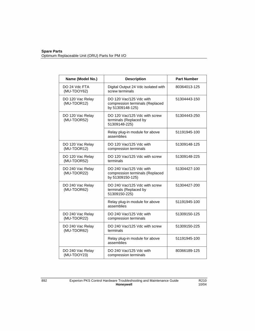
Spare PartsOptimum Replaceable Unit (ORU) Parts for PM I/O
892 Experion PKS Control Hardware Troubleshooting and Maintenance Guide R210Honeywell 10/04
Name (Model No.) Description Part Number
DO 24 Vdc FTA (MU-TDOY62)
Digital Output 24 Vdc isolated withscrew terminals
80364013-125
DO 120 Vac Relay (MU-TDOR12)
DO 120 Vac/125 Vdc withcompression terminals (Replacedby 51309148-125)
51304443-150
DO 120 Vac/125 Vdc with screwterminals (Replaced by51309148-225)
51304443-250DO 120 Vac Relay (MU-TDOR52)
Relay plug-in module for aboveassemblies
51191945-100
DO 120 Vac Relay (MU-TDOR12)
DO 120 Vac/125 Vdc withcompression terminals
51309148-125
DO 120 Vac Relay (MU-TDOR52)
DO 120 Vac/125 Vdc with screwterminals
51309148-225
DO 240 Vac Relay (MU-TDOR22)
DO 240 Vac/125 Vdc withcompression terminals (Replacedby 51309150-125)
51304427-100
DO 240 Vac/125 Vdc with screwterminals (Replaced by51309150-225)
51304427-200DO 240 Vac Relay (MU-TDOR62)
Relay plug-in module for aboveassemblies
51191945-100
DO 240 Vac Relay (MU-TDOR22)
DO 240 Vac/125 Vdc withcompression terminals
51309150-125
DO 240 Vac/125 Vdc with screwterminals
51309150-225DO 240 Vac Relay (MU-TDOR62)
Relay plug-in module for aboveassemblies
51191945-100
DO 240 Vac Relay (MU-TDOY23)
DO 240 Vac/125 Vdc withcompression terminals
80366189-125

Spare PartsOptimum Replaceable Unit (ORU) Parts for PM I/O
R210 Experion PKS Control Hardware Troubleshooting and Maintenance Guide 89310/04 Honeywell
Name (Model No.) Description Part Number
DO 240 Vac/125 Vdc with screwterminals
80366186-125
Relay (NT1) for above assemblies 83970001-110
DO 240 Vac Relay (MU-TDOY63)
Jumper for above assemblies 51190610-101
DI Power Dist Assy (MU-TDPR02)
Digital Input Power DistributionAssembly
51304425-125
DO Standby Manual (MU-SMDC02)
Digital Output Standby ManualDevice with case
51304526-100
DO Standby Manual (MU-SMDX02)
Digital Output Standby ManualDevice with case and cable
51304527-100
AO Standby Manual (MU-SMAC02)
Analog Output Standby ManualDevice Assy with cable
51401277-100
Manual/Auto Station (MU-MASX02)
Honeywell Manual/Auto Station Part numberPC6001-U-2MO-
40-A0
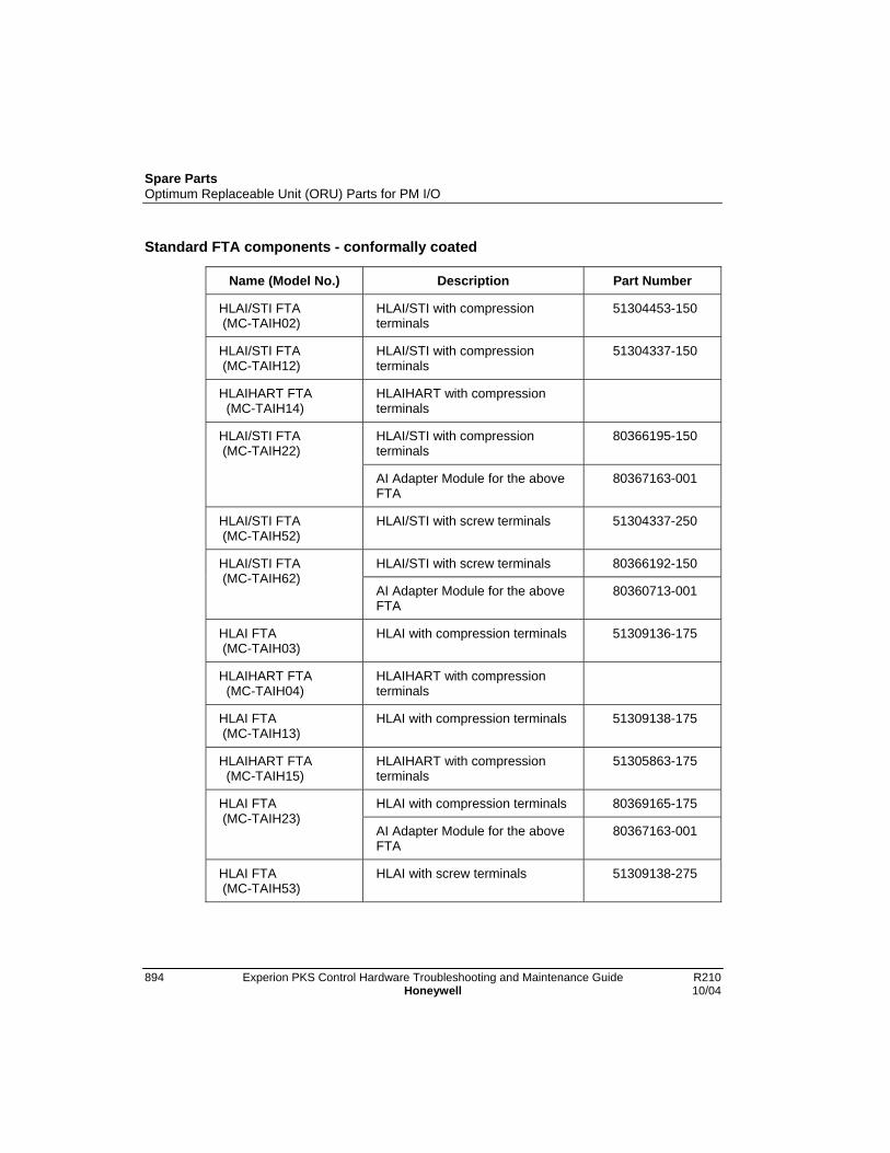
Spare PartsOptimum Replaceable Unit (ORU) Parts for PM I/O
894 Experion PKS Control Hardware Troubleshooting and Maintenance Guide R210Honeywell 10/04
Standard FTA components - conformally coated
Name (Model No.) Description Part Number
HLAI/STI FTA (MC-TAIH02)
HLAI/STI with compressionterminals
51304453-150
HLAI/STI FTA (MC-TAIH12)
HLAI/STI with compressionterminals
51304337-150
HLAIHART FTA (MC-TAIH14)
HLAIHART with compressionterminals
HLAI/STI with compressionterminals
80366195-150HLAI/STI FTA (MC-TAIH22)
AI Adapter Module for the aboveFTA
80367163-001
HLAI/STI FTA (MC-TAIH52)
HLAI/STI with screw terminals 51304337-250
HLAI/STI with screw terminals 80366192-150HLAI/STI FTA (MC-TAIH62)
AI Adapter Module for the aboveFTA
80360713-001
HLAI FTA (MC-TAIH03)
HLAI with compression terminals 51309136-175
HLAIHART FTA (MC-TAIH04)
HLAIHART with compressionterminals
HLAI FTA (MC-TAIH13)
HLAI with compression terminals 51309138-175
HLAIHART FTA (MC-TAIH15)
HLAIHART with compressionterminals
51305863-175
HLAI with compression terminals 80369165-175HLAI FTA (MC-TAIH23)
AI Adapter Module for the aboveFTA
80367163-001
HLAI FTA (MC-TAIH53)
HLAI with screw terminals 51309138-275
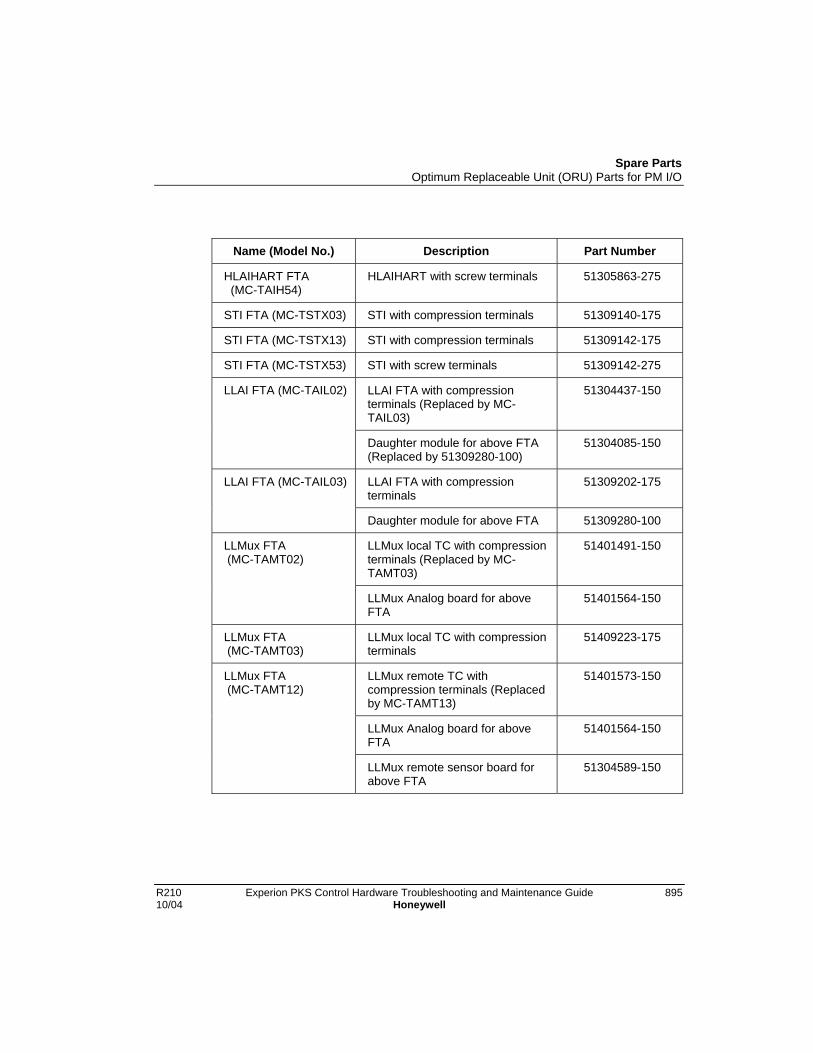
Spare PartsOptimum Replaceable Unit (ORU) Parts for PM I/O
R210 Experion PKS Control Hardware Troubleshooting and Maintenance Guide 89510/04 Honeywell
Name (Model No.) Description Part Number
HLAIHART FTA (MC-TAIH54)
HLAIHART with screw terminals 51305863-275
STI FTA (MC-TSTX03) STI with compression terminals 51309140-175
STI FTA (MC-TSTX13) STI with compression terminals 51309142-175
STI FTA (MC-TSTX53) STI with screw terminals 51309142-275
LLAI FTA with compressionterminals (Replaced by MC-TAIL03)
51304437-150LLAI FTA (MC-TAIL02)
Daughter module for above FTA(Replaced by 51309280-100)
51304085-150
LLAI FTA with compressionterminals
51309202-175LLAI FTA (MC-TAIL03)
Daughter module for above FTA 51309280-100
LLMux local TC with compressionterminals (Replaced by MC-TAMT03)
51401491-150LLMux FTA (MC-TAMT02)
LLMux Analog board for aboveFTA
51401564-150
LLMux FTA (MC-TAMT03)
LLMux local TC with compressionterminals
51409223-175
LLMux remote TC withcompression terminals (Replacedby MC-TAMT13)
51401573-150
LLMux Analog board for aboveFTA
51401564-150
LLMux FTA (MC-TAMT12)
LLMux remote sensor board forabove FTA
51304589-150

Spare PartsOptimum Replaceable Unit (ORU) Parts for PM I/O
896 Experion PKS Control Hardware Troubleshooting and Maintenance Guide R210Honeywell 10/04
Name (Model No.) Description Part Number
LLMux FTA (MC-TAMT13)
LLMux remote TC withcompression terminals
51409213-175
LLMux RTD with compressionterminals (Replaced by MC-TAMR03)
51304477-150LLMux FTA (MC-TAMR02)
LLMux daughter board for aboveFTA
51401364-100
LLMux FTA (MC-TAMR03)
LLMux RTD with compressionterminals
51309218-125
RHMUX FTA (MC-GRMT01)
RHMUX TC with screw terminals 51404106-175
RHMUX GI/IS PowerAdapter (MC-GRPA01)
RHMUXGI/IS Power Adapter withcompression terminals
51304724-175
RHMUX GI/NI PowerAdapter (MC-TRPA01)
RHMUX GI/NI Power Adapter withcompression terminals
51304722-175
AO FTA (MC-THAO11) Analog Output with HART andcomp. terminals
51309542-175
AO FTA (MC-TAOX02) Analog Output with compressionterminals
51304476-175
AO FTA (MC-TAOX12) Analog Output with compressionterminals
51304335-175
Analog Output with screwterminals
51304335-275AO FTA (MC-TAOX52)
Plug-in module for above FTAs 51304338-150
AO FTA (MC-TAOY22) Analog Output with comp term,Stdby Manual
80366481-175
AO FTA (MC-TAOY23) Analog Output with comp term, noStdby Manual
80366177-250
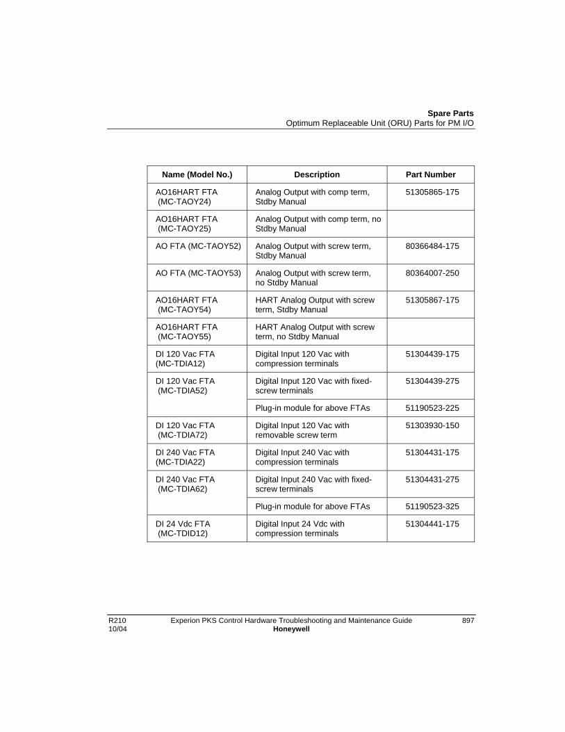
Spare PartsOptimum Replaceable Unit (ORU) Parts for PM I/O
R210 Experion PKS Control Hardware Troubleshooting and Maintenance Guide 89710/04 Honeywell
Name (Model No.) Description Part Number
AO16HART FTA (MC-TAOY24)
Analog Output with comp term,Stdby Manual
51305865-175
AO16HART FTA (MC-TAOY25)
Analog Output with comp term, noStdby Manual
AO FTA (MC-TAOY52) Analog Output with screw term,Stdby Manual
80366484-175
AO FTA (MC-TAOY53) Analog Output with screw term,no Stdby Manual
80364007-250
AO16HART FTA (MC-TAOY54)
HART Analog Output with screwterm, Stdby Manual
51305867-175
AO16HART FTA (MC-TAOY55)
HART Analog Output with screwterm, no Stdby Manual
DI 120 Vac FTA(MC-TDIA12)
Digital Input 120 Vac withcompression terminals
51304439-175
Digital Input 120 Vac with fixed-screw terminals
51304439-275DI 120 Vac FTA (MC-TDIA52)
Plug-in module for above FTAs 51190523-225
DI 120 Vac FTA (MC-TDIA72)
Digital Input 120 Vac withremovable screw term
51303930-150
DI 240 Vac FTA(MC-TDIA22)
Digital Input 240 Vac withcompression terminals
51304431-175
Digital Input 240 Vac with fixed-screw terminals
51304431-275DI 240 Vac FTA (MC-TDIA62)
Plug-in module for above FTAs 51190523-325
DI 24 Vdc FTA (MC-TDID12)
Digital Input 24 Vdc withcompression terminals
51304441-175

Spare PartsOptimum Replaceable Unit (ORU) Parts for PM I/O
898 Experion PKS Control Hardware Troubleshooting and Maintenance Guide R210Honeywell 10/04
Name (Model No.) Description Part Number
Digital Input 24 Vdc with fixed-screw terminals
51304441-275DI 24 Vdc FTA (MC-TDID52)
Plug-in module for above FTAs 51190523-125
DI 24 Vdc FTA (MC-TDID72)
Digital Input 24 Vdc withremovable screw term
51303928-150
DI 24 Vdc FTA (MC-TDIY22)
Digital Input 24 Vdc withcompression terminals
80366180-175
DI 24 Vdc FTA (MC-TDIY62)
Digital Input 24 Vdc with screwterminals
80364010-175
DO 120/240 Vac FTA (MC-TDOA12)
Digital Output 120/240 Vac SSwith fixed-comp term (Replacedby MC-TDOA13)
51304408-150
Digital Output 120/240 Vac SSwith fixed-screw term (Replacedby MC-TDOA53)
51304408-250DO 120/240 Vac FTA (MC-TDOA52)
Solid-state relay plug-in modulefor above FTAs
51190516-325
DO 120/240 Vac FTA (MC-TDOA13)
Digital Output 24-240 Vac SS withremovable compression terminals.
51304648-175
Digital Output 24-240 Vac SS withremovable screw terminals
51304648-275DO 120/240 Vac FTA (MC-TDOA53)
Solid-state relay plug-in modulefor above FTAs
51190516-332
DO 3-30 Vdc FTA (MC-TDOD12)
Digital Output 3-30 Vdc SS withfixed-comp term (Replaced byMC-TDOD13)
51304423-150
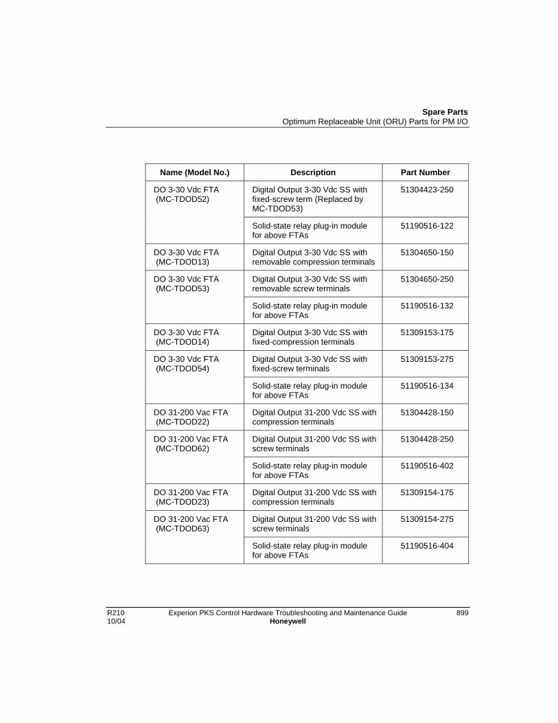
Spare PartsOptimum Replaceable Unit (ORU) Parts for PM I/O
R210 Experion PKS Control Hardware Troubleshooting and Maintenance Guide 89910/04 Honeywell
Name (Model No.) Description Part Number
Digital Output 3-30 Vdc SS withfixed-screw term (Replaced byMC-TDOD53)
51304423-250DO 3-30 Vdc FTA (MC-TDOD52)
Solid-state relay plug-in modulefor above FTAs
51190516-122
DO 3-30 Vdc FTA (MC-TDOD13)
Digital Output 3-30 Vdc SS withremovable compression terminals
51304650-150
Digital Output 3-30 Vdc SS withremovable screw terminals
51304650-250DO 3-30 Vdc FTA (MC-TDOD53)
Solid-state relay plug-in modulefor above FTAs
51190516-132
DO 3-30 Vdc FTA (MC-TDOD14)
Digital Output 3-30 Vdc SS withfixed-compression terminals
51309153-175
Digital Output 3-30 Vdc SS withfixed-screw terminals
51309153-275DO 3-30 Vdc FTA (MC-TDOD54)
Solid-state relay plug-in modulefor above FTAs
51190516-134
DO 31-200 Vac FTA (MC-TDOD22)
Digital Output 31-200 Vdc SS withcompression terminals
51304428-150
Digital Output 31-200 Vdc SS withscrew terminals
51304428-250DO 31-200 Vac FTA (MC-TDOD62)
Solid-state relay plug-in modulefor above FTAs
51190516-402
DO 31-200 Vac FTA (MC-TDOD23)
Digital Output 31-200 Vdc SS withcompression terminals
51309154-175
Digital Output 31-200 Vdc SS withscrew terminals
51309154-275DO 31-200 Vac FTA (MC-TDOD63)
Solid-state relay plug-in modulefor above FTAs
51190516-404
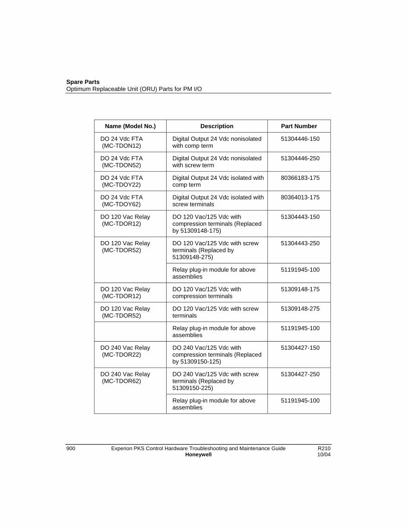
Spare PartsOptimum Replaceable Unit (ORU) Parts for PM I/O
900 Experion PKS Control Hardware Troubleshooting and Maintenance Guide R210Honeywell 10/04
Name (Model No.) Description Part Number
DO 24 Vdc FTA (MC-TDON12)
Digital Output 24 Vdc nonisolatedwith comp term
51304446-150
DO 24 Vdc FTA (MC-TDON52)
Digital Output 24 Vdc nonisolatedwith screw term
51304446-250
DO 24 Vdc FTA (MC-TDOY22)
Digital Output 24 Vdc isolated withcomp term
80366183-175
DO 24 Vdc FTA (MC-TDOY62)
Digital Output 24 Vdc isolated withscrew terminals
80364013-175
DO 120 Vac Relay (MC-TDOR12)
DO 120 Vac/125 Vdc withcompression terminals (Replacedby 51309148-175)
51304443-150
DO 120 Vac/125 Vdc with screwterminals (Replaced by51309148-275)
51304443-250DO 120 Vac Relay (MC-TDOR52)
Relay plug-in module for aboveassemblies
51191945-100
DO 120 Vac Relay (MC-TDOR12)
DO 120 Vac/125 Vdc withcompression terminals
51309148-175
DO 120 Vac Relay (MC-TDOR52)
DO 120 Vac/125 Vdc with screwterminals
51309148-275
Relay plug-in module for aboveassemblies
51191945-100
DO 240 Vac Relay (MC-TDOR22)
DO 240 Vac/125 Vdc withcompression terminals (Replacedby 51309150-125)
51304427-150
DO 240 Vac/125 Vdc with screwterminals (Replaced by51309150-225)
51304427-250DO 240 Vac Relay (MC-TDOR62)
Relay plug-in module for aboveassemblies
51191945-100

Spare PartsOptimum Replaceable Unit (ORU) Parts for PM I/O
R210 Experion PKS Control Hardware Troubleshooting and Maintenance Guide 90110/04 Honeywell
Name (Model No.) Description Part Number
DO 240 Vac Relay (MC-TDOR22)
DO 240 Vac/125 Vdc withcompression terminals
51309150-175
DO 240 Vac/125 Vdc with screwterminals
51309150-275DO 240 Vac Relay (MC-TDOR62)
Relay plug-in module for aboveassemblies
51191945-150
DO 240 Vac Relay (MC-TDOY23)
DO 240 Vac/125 Vdc withcompression terminals
80366189-175
DO 240 Vac/125 Vdc with screwterminals
80366185-175
Relay (NT1) for above assemblies 83970001-110
DO 240 Vac Relay (MC-TDOY63)
Jumper for above assemblies 51190610-101
Power Adapter (MC-TLPA02)
Power Adapter (Used with LLMux) 51309204-175
DI Power Dist Assy (MC-TDPR02)
Digital Input Power DistributionAssembly
51304425-175
DO Standby Manual (MC-SMDC02)
Digital Output Standby ManualDevice with case
51304526-150
DO Standby Manual (MC-SMDX02)
Digital Output Standby ManualDevice with case and cable
51304527-150
AO Standby Manual (MC-SMAC02)
Analog Output Standby ManualDevice Assy with cable
51401277-150

Spare PartsOptimum Replaceable Unit (ORU) Parts for PM I/O
902 Experion PKS Control Hardware Troubleshooting and Maintenance Guide R210Honeywell 10/04
Galvanically Isolated FTA components - non-conformally coated
Name (Model No.) Description Part Number
HLAI FTA (MU-GAIH12)
HLAI FTA with GI Modules(Compress terminals) (Replacedby MU-GAIH13 – 51304718-125)
51304636-100
HLAI FTA with GI Modules (Crimpterminals) (Replaced by MU-GAIH83 – 51304718-325)
51304636-300HLAI FTA (MU-GAIH82)
HLAI Galvanic Isolation Module(MTL4041)
51191697-100
HLAI FTA with GI Modules(Compress terminals)
51304718-125HLAI FTA (MU-GAIH13)
HLAI Galvanic Isolation Module(MTL4041B)
51191697-200
HLAI FTA with GI Modules (Crimpterminals)
51304718-325HLAI FTA (MU-GAIH83)
HLAI Galvanic Isolation Module(MTL4041B)
51191697-200
HLAI FTA with GI Modules(Compress terminals)
51304730-125HLAI FTA (MU-GAIH14)
HLAI Galvanic Isolation ModuleMTL4041P)
51191928-100
HLAI FTA with GI Modules (Crimpterminals)
51304730-325HLAI FTA (MU-GAIH84)
HLAI Galvanic Isolation ModuleMTL4041P)
51191928-100
HLAI FTA with GI Modules(Compress terminals)
51304748-125HLAI FTA (MU-GAIH22)
HLAI Galvanic Isolation Module(MTL4041B)
51191697-200

Spare PartsOptimum Replaceable Unit (ORU) Parts for PM I/O
R210 Experion PKS Control Hardware Troubleshooting and Maintenance Guide 90310/04 Honeywell
Name (Model No.) Description Part Number
HLAI FTA with GI Modules (Crimpterminals)
51304748-325HLAI FTA (MU-GAIH92)
HLAI Galvanic Isolation Module(MTL4041B)
51191697-200
HLAI Calibration Tool HLAI calibration tool 51201450-100
24 Vdc DI FTA (MU-GDID12)
24 Vdc DI FTA with GI Modules(Compress Term)
51304640-125
24 Vdc DI FTA with GI Modules(Crimp Terminals)
51304640-32524 Vdc DI FTA (MU-GDID82)
24 Vdc DI Galvanic IsolationModule (MTL4016)
51191699-100
24 Vdc DI FTA (MU-GDID13)
24 Vdc DI FTA with GI Modules(Compress Term)
51304728-125
24 Vdc DI FTA with GI Modules(Crimp Terminals)
51304728-32524 Vdc DI FTA (MU-GDID83)
24 Vdc DI Galvanic IsolationModule (MTL4013)
51191926-100
AO FTA (MU-GHAO11)
AO nonredun FTA with HART andComp Term
51309540-125
AO HART redundant FTA with GIModules (Comp Term)
51305869-125AO16HART FTA(MU-GHAO21)
AO Galvanic Isolation Module(MTL4046C)
AO FTA (MU-GAOX02)
AO nonredun FTA with GIModules (Comp Term)
51304638-125
AO FTA (MU-GAOX72)
AO nonredun FTA with GIModules (Crimp Term)
51304638-325
AO FTA (MU-GAOX12)
AO redundant FTA with GIModules (Comp Term)
51304638-525

Spare PartsOptimum Replaceable Unit (ORU) Parts for PM I/O
904 Experion PKS Control Hardware Troubleshooting and Maintenance Guide R210Honeywell 10/04
Name (Model No.) Description Part Number
AO redundant FTA with GIModules (Crimp Term)
51304638-725
AO Galvanic Isolation Module(MTL4045C)
51192097-200
AO Galvanic Isolation Module(MTL4046P)
51192565-100
AO FTA (MU-GAOX82)
Redundancy Module for FTA 51304338-100
DO FTA (MU-GDOD12)
DO FTA with GI Modules(Compression Terminals)
51304642-125
DO FTA with GI Modules (CrimpTerminals)
51304642-325DO FTA (MU-GDOD82)
DO Galvanic Isolation Module(MTL4021)
51191698-100
DO FTA (MU-GDOL12)
DO FTA with GI Modules(Compression Terminals)
51304736-125
DO FTA with GI Modules (CrimpTerminals)
51304736-325DO FTA (MU-GDOL82)
DO Galvanic Isolation Module(MTL4023)
51191927-100
LFD Combiner Panel(MU-GLFD02)
Line Fault Detection CombinerPanel
51304732-125
Power DistributionAssembly (MU-GPRD02)
Galvanic Isolation PowerDistribution Assembly
51304644-125
Marshalling Panel (MU-GMAR52)
Marshalling Panel 51309156-125

Spare PartsOptimum Replaceable Unit (ORU) Parts for PM I/O
R210 Experion PKS Control Hardware Troubleshooting and Maintenance Guide 90510/04 Honeywell
Name (Model No.) Description Part Number
Comp-type terminal connector forGI Modules
51191738-100
Crimp-type terminal connector forGI Modules
51191737-100
GI Module Connector
14-20 AWG wire crimp pins forabove connector
51191737-201

Spare PartsOptimum Replaceable Unit (ORU) Parts for PM I/O
906 Experion PKS Control Hardware Troubleshooting and Maintenance Guide R210Honeywell 10/04
Galvanically Isolated FTA components - conformally coated
Name (Model No.) Description Part Number
HLAI FTA (MC-GAIH12)
HLAI FTA with GI Modules(Compress terminals) (Replacedby MU-GAIH13 – 51304718-125)
51304636-150
HLAI FTA with GI Modules (Crimpterminals) (Replaced by MU-GAIH83 – 51304718-325)
51304636-350HLAI FTA (MC-GAIH82)
HLAI Galvanic Isolation Module(MTL4041)
51191697-100
HLAI FTA with GI Modules(Compress terminals)
51304718-175HLAI FTA (MC-GAIH13)
HLAI Galvanic Isolation Module(MTL4041B)
51191697-200
HLAI FTA with GI Modules (Crimpterminals)
51304718-375HLAI FTA (MC-GAIH83)
HLAI Galvanic Isolation Module(MTL4041B)
51191697-200
HLAI FTA with GI Modules(Compress terminals)
51304730-175HLAI FTA (MC-GAIH14)
HLAI Galvanic Isolation ModuleMTL4041P)
51191928-100
HLAI FTA with GI Modules (Crimpterminals)
51304730-375HLAI FTA (MC-GAIH84)
HLAI Galvanic Isolation ModuleMTL4041P)
51191928-100
HLAI FTA with GI Modules(Compress terminals)
51304748-175HLAI FTA (MC-GAIH22)
HLAI Galvanic Isolation Module(MTL4041B)
51191697-200

Spare PartsOptimum Replaceable Unit (ORU) Parts for PM I/O
R210 Experion PKS Control Hardware Troubleshooting and Maintenance Guide 90710/04 Honeywell
Name (Model No.) Description Part Number
HLAI FTA with GI Modules (Crimpterminals)
51304748-375HLAI FTA (MC-GAIH92)
HLAI Galvanic Isolation Module(MTL4041B)
51191697-200
HLAI Calibration Tool HLAI calibration tool 51201450-100
24 Vdc DI FTA (MC-GDID12)
24 Vdc DI FTA with GI Modules(Compress Term)
51304640-175
24 Vdc DI FTA with GI Modules(Crimp Terminals)
51304640-37524 Vdc DI FTA (MC-GDID82)
24 Vdc DI Galvanic IsolationModule (MTL4016)
51191699-100
24 Vdc DI FTA(MC-GDID13)
24 Vdc DI FTA with GI Modules(Compress Term)
51304728-175
24 Vdc DI FTA with GI Modules(Crimp Terminals)
51304728-37524 Vdc DI FTA (MC-GDID83)
24 Vdc DI Galvanic IsolationModule (MTL4013)
51191926-100
AO FTA (MC-GHAO11)
AO nonredun FTA with HART andComp Term
51309540-175
AO HART redundant FTA with GIModules (Comp Term)
51305869-175AO16HART FTA(MC-GHAO21)
AO Galvanic Isolation Module(MTL4046C)
AO FTA (MC-GAOX02)
AO nonredun FTA with GIModules (Comp Term)
51304638-175
AO FTA (MC-GAOX72)
AO nonredun FTA with GIModules (Crimp Term)
51304638-375
AO FTA (MC-GAOX12)
AO redundant FTA with GIModules (Comp Term)
51304638-575

Spare PartsOptimum Replaceable Unit (ORU) Parts for PM I/O
908 Experion PKS Control Hardware Troubleshooting and Maintenance Guide R210Honeywell 10/04
Name (Model No.) Description Part Number
AO redundant FTA with GIModules (Crimp Term)
51304638-775
AO Galvanic Isolation Module(MTL4045C)
51192097-200
AO Galvanic Isolation Module(MTL4046P)
51192565-100
AO FTA (MC-GAOX82)
Redundancy Module for FTA 51304338-100
DO FTA (MC-GDOD12)
DO FTA with GI Modules(Compression Terminals)
51304642-175
DO FTA with GI Modules (CrimpTerminals)
51304642-375DO FTA (MC-GDOD82)
DO Galvanic Isolation Module(MTL4021)
51191698-100
DO FTA (MC-GDOL12)
DO FTA with GI Modules(Compression Terminals)
51304736-175
DO FTA with GI Modules (CrimpTerminals)
51304736-375DO FTA (MC-GDOL82)
DO Galvanic Isolation Module(MTL4023)
51191927-100
LFD Combiner Panel (MC-GLFD02)
Line Fault Detection CombinerPanel
51304732-175
Power DistributionAssembly (MC-GPRD02)
Galvanic Isolation PowerDistribution Assembly
51304644-175
Marshalling Panel (MC-GMAR52)
Marshalling Panel 51309156-175

Spare PartsOptimum Replaceable Unit (ORU) Parts for PM I/O
R210 Experion PKS Control Hardware Troubleshooting and Maintenance Guide 90910/04 Honeywell
Name (Model No.) Description Part Number
Comp-type terminal connector forGI Modules
51191738-100
Crimp-type terminal connector forGI Modules
51191737-100
GI Module Connector
14-20 AWG wire crimp pins forabove connector
51191737-201
Miscellaneous components - non-conformally coated
Name (Model No.) Description Part Number
Card Case Plastic case for IOP cards 51304072-100
Label - Plain blue for IOP fillercard
51109474-100
Label for Low Level Analog InputIOP
51109475-100
Label for High Level Analog InputIOP
51109476-100
Label for Analog Output IOP 51109477-100
Label for Digital Input IOP 51109478-100
Label for Digital Output IOP 51109479-100
Label for I/O Link Extender 51109480-100
Label for Low Level MultiplexerIOP
51109486-100
Card Label
Label for Smart TransmitterInterface IOP
51109494-100
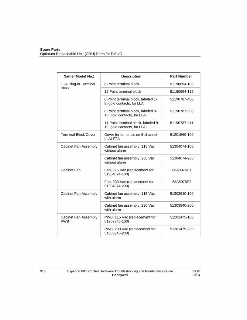
Spare PartsOptimum Replaceable Unit (ORU) Parts for PM I/O
910 Experion PKS Control Hardware Troubleshooting and Maintenance Guide R210Honeywell 10/04
Name (Model No.) Description Part Number
8 Point terminal block 51190694-108
12 Point terminal block 51190694-112
8 Point terminal block, labeled 1-8, gold contacts, for LLAI
51190787-408
8 Point terminal block, labeled 9-16, gold contacts, for LLAI
51190787-508
FTA Plug-in TerminalBlock
11 Point terminal block, labeled 9-19, gold contacts, for LLAI
51190787-411
Terminal Block Cover Cover for terminals on 8-channelLLAI FTA
51201569-100
Cabinet fan assembly, 115 Vacwithout alarm
51304074-100Cabinet Fan Assembly
Cabinet fan assembly, 230 Vacwithout alarm
51304074-200
Fan, 115 Vac (replacement for51304074-100)
68A8976P1Cabinet Fan
Fan, 230 Vac (replacement for51304074-200)
68A8976P2
Cabinet fan assembly, 115 Vacwith alarm
51303940-100Cabinet Fan Assembly
Cabinet fan assembly, 230 Vacwith alarm
51303940-200
PWB, 115 Vac (replacement for51303940-100)
51201475-100Cabinet Fan AssemblyPWB
PWB, 230 Vac (replacement for51303940-200)
51201475-200

Spare PartsOptimum Replaceable Unit (ORU) Parts for PM I/O
R210 Experion PKS Control Hardware Troubleshooting and Maintenance Guide 91110/04 Honeywell
Name (Model No.) Description Part Number
Left 7- Slot Card File (MU-HPFH01)
Left 7-Slot IOPcard file assy (slots1-7)
51404125-100
Left 7- Slot Card File (MU-HPFI03)
Left 7-Slot IOP card file assy(slots 1-7)
51404191-225
Left 7- Slot Card FileBackpanel
Left 7-Slot card file backpanelassy (slots 1-7)
51401626-100
Right 7- Slot Card File (MU-HPFH11)
Right 7- Slot IOP card file assy (9-15)
51404126-100
Right 7- Slot Card File (MU-HPFI13)
Right 7- Slot IOP card file assy(slots 9-15)
51404192-225
Right 7- Slot Card FileBackpanel
Right 7- Slot card file backpanelassy (slots 9-15)
51401629-100
IOP Only Card File (MU-IOFX02)
15 IOP Only card file assembly 51401546-100
IOP Only Card FileBackpanel
15 IOP Only card file backpanelassembly
51402599-100
IOP Only Card File (MU-IOFX03)
15 IOP Only card file assembly 51404210-125
IOP Only Card FileBackpanel
15 IOP Only card file backpanelassembly
51402599-125
Filler Plate Filler plate between 7-Slot cardfiles
51304720-100
Opto-Isolator Solid-state opto-isolator for cardfiles
51190516-202
Fuse Holder/Puller Fuse holder/puller (15 IOP cardfile)
51190586-100

Spare PartsOptimum Replaceable Unit (ORU) Parts for PM I/O
912 Experion PKS Control Hardware Troubleshooting and Maintenance Guide R210Honeywell 10/04
Name (Model No.) Description Part Number
100 ohm range resistor 51190102-100Range Resistor
250 ohm range resistor 51190102-200
Zero Ohm Resistor Zero ohm resistor for PowerSystem backpanel when addingBattery Pack assembly
51190101-100
Miscellaneous components - conformally coated
Name (Model No.) Description Part Number
Cabinet fan assembly, 115 Vacwithout alarm
51304074-150Cabinet Fan Assembly
Cabinet fan assembly, 230 Vacwithout alarm
51304074-250
Fan, 115 Vac (replacement for51304074-100)
68A8976P1Cabinet Fan
Fan, 230 Vac (replacement for51304074-200)
68A8976P2
Cabinet fan assembly, 115 Vacwith alarm
51303940-150Cabinet Fan Assembly
Cabinet fan assembly, 230 Vacwith alarm
51303940-250
PWB, 115 Vac (replacement for51303940-100)
51201475-150Cabinet Fan AssemblyPWB
PWB, 230 Vac (replacement for51303940-200)
51201475-250
Left 7- Slot Card File (MC-HPFH01)
Left 7-Slot IOPcard file assy (slots1-7)
51404125-150

Spare PartsOptimum Replaceable Unit (ORU) Parts for PM I/O
R210 Experion PKS Control Hardware Troubleshooting and Maintenance Guide 91310/04 Honeywell
Name (Model No.) Description Part Number
Left 7- Slot Card File (MC-HPFI03)
Left 7-Slot IOP card file assy(slots 1-7)
51404191-275
Left 7- Slot Card FileBackpanel
Left 7-Slot card file backpanelassy (slots 1-7)
51401626-150
Right 7- Slot Card File (MC-HPFH11)
Right 7- Slot IOP card file assy (9-15)
51404126-150
Right 7- Slot Card File (MC-HPFI13)
Right 7- Slot IOP card file assy(slots 9-15)
51404192-275
Right 7- Slot Card FileBackpanel
Right 7- Slot card file backpanelassy (slots 9-15)
51401629-150
IOP Only Card File (MC-IOFX02)
15 IOP Only card file assembly 51401546-150
IOP Only Card FileBackpanel
15 IOP Only card file backpanelassembly
51402599-150
IOP Only Card File (MC-IOFX03)
15 IOP Only card file assembly 51404210-175
IOP Only Card FileBackpanel
15 IOP Only card file backpanelassembly
51402599-175
Filler Plate Filler plate between 7-Slot cardfiles
51304720-150

Spare PartsOptimum Replaceable Unit (ORU) Parts for PM I/O
914 Experion PKS Control Hardware Troubleshooting and Maintenance Guide R210Honeywell 10/04


Automation and Control SolutionsHoneywell International Inc.1100 Virginia DriveFort Washington, PA 19034