CONTROL - EFKA · EFKA DA82GA3312 5 1 Putting into Service Before putting the control into service,...
36
CONTROL DA82GA3312 with control panel V810/V820 LIST OF PARAMETERS CONNECTION DIAGRAM TIMING DIAGRAMS No. 402276 English FRANKL & KIRCHNER EFKA OF AMERICA INC. EFKA ELECTRONIC MOTORS GMBH & CO KG SINGAPORE PTE. LTD.
Transcript of CONTROL - EFKA · EFKA DA82GA3312 5 1 Putting into Service Before putting the control into service,...

CONTROL DA82GA3312
with control panel V810/V820
LIST OF PARAMETERS CONNECTION DIAGRAM TIMING DIAGRAMS
No. 402276 English
FRANKL & KIRCHNER EFKA OF AMERICA INC. EFKA ELECTRONIC MOTORS GMBH & CO KG SINGAPORE PTE. LTD.


EFKA DA82GA3312 3 CONTENTS Page
1 Putting into Service 5
2 Socket Connectors 5
2.1 Position in the Control 5 2.2 Connection Diagram 6
3 Timing Diagrams 9
4 List of Parameters 20
4.1 Operator Level 20 4.2 Technician Level 21 4.3 Supplier Level 28
5 Error Displays 31
6 Slide-in Strips for the V810 Control Panel 32


EFKA DA82GA3312 5 1 Putting into Service Before putting the control into service, the following must be ensured, checked and/or adjusted: The correct installation of the drive, position transmitter and accompanying devices, if necessary The correct adjustment of the direction of motor rotation using parameter 161 The machine select, which can be verified using parameter 280 If necessary, the setting of the reference position using parameter 170 If necessary, the setting of the positions using parameter 171 If necessary, the correct positioning speed using parameter 110 If necessary, the correct maximum speed compatible with the sewing machine using parameter 111 If necessary, the setting of the remaining relevant parameters Start sewing in order to save the set values
See instruction manual for details! 2 Socket Connectors 2.1 Position in the Control
B1 Position transmitter B2 Commutation transmitter for d.c. motor A (ST2) Inputs and outputs B (B4) Inputs and outputs C (B5) Inputs and outputs D (B3) Keys and light emitting diodes B18 Light barrier module / interface B80 Actuator B776 Control panel Variocontrol (as shown: 9/25-pin adapter plugged in) *) Type designation
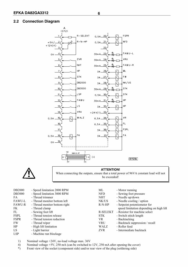
EFKA DA82GA3312 6 2.2 Connection Diagram
DB2000 - Speed limitation 2000 RPM ML - Motor running DB3000 - Speed limitation 3000 RPM NFD - Sewing foot pressure FA - Thread trimmer NHT - Needle up/down FAWU-L - Thread monitor bottom left NK/US - Needle cooling / option FAWU-R - Thread monitor bottom right R-N-HP - Setpoint potentiometer for FK - Thread clamp speed limitation depending on high lift FL - Sewing foot lift R-SELEKT - Resistor for machine select FSPL - Thread tension release STK - Switch stitch length FSPR - Thread tension reduction VR - Backtacking FW - Thread wiper VRU - Backtack suppression / recall HP - High lift limitation WALZ - Roller feed LS - Light barrier ZVR - Intermediate backtack LSP - Machine run blockage
1) Nominal voltage +24V, no-load voltage max. 36V 4) Nominal voltage +5V, 250 mA (can be switched to 12V, 250 mA after opening the cover) *) Front view of the socket (component side) and/or rear view of the plug (soldering side)
ATTENTION! When connecting the outputs, ensure that a total power of 96VA constant load will not
be exceeded!

EFKA DA82GA3312 7
DB3000 - Speed limitation 3000 RPM ML/FSPL2 - Motor running/2nd thread tension release NHT - Needle up/down (selectable using parameter 198) FF - Flip-flop NFD - Sewing foot pressure FSPL - Thread tension release POS2 - Position 2 FSPR - Thread tension reduction STK - Switch stitch length HP - High lift limitation VR - Backtacking IMPULSE - Speedometer impulses (512/rotation) VRU - Backtack suppression / recall LSP - Machine run blockage WALZ - Roller feed ML - Motor running ZVR - Intermediate backtack
1) Nominal voltage 24V, no-load voltage max. 36V 2) 0V connection of the load circuit *) Front view of the socket (component side) and/or rear view of the plug (soldering side)
ATTENTION! When connecting the outputs, ensure that a total power of 96VA constant load will not
be exceeded!

EFKA DA82GA3312 8
LSHQ Light barrier command (identified when switched to 0V) LSM001 or LSM001A Light barrier module
EB.. Actuator
Pedal step -2 -1 0 ½ 1 2 3 4 5 6 7 8 9 10 11 12 Input A L L H H H L L H H L L H H L L H Input B L H H L L L H H H H L L L L H H Input C H H H H L L L L L L L L H H H H Input D H H H H H H H H L L L L L L L L
Switching supply voltage 5V or 12V
There is a supply voltage of +5V for external devices on the A/2 socket. After opening the cover, this voltage can be changed to +12V by replugging a multipole connector J1 on the printed circuit board. Open cover +5V = Connect lefthand pins 1 and 2 with jumper
(factory setting) +12V = Connect righthand pins 3 and 4 with jumper Close cover
ATTBefore openin
ENTION! g the control box, turn power off!
J1 1
2
+ 5 V
4
3 1
2
+ 1 2 V
KL2303
J1 J1
4
3

EFKA DA82GA3312 9 3 Timing Diagrams Trimming from full machine run
0
N K
A/28
0
A/35
A/30
A/34
P O S .2
S T K
F S P L
A/36
A/27
A/37
F W
FA
V R
F L t3
P O S .1
- 1/ 2
-2-1 0
n
+
1
t1ArrArv
1 2 3 1 2 3
n3 n2
0214/FALAUF
E rr E rv
iFA
F S E F S A
t6
tFA
n4 n7
321321
n7
t4t7 t5
Mark Function Parameter V810 V820 Double start backtack On Key 1 Key 1 Double end backtack On Key 2 Key 4 Slu Long stitches during backtack On 137 = ON n2 Maximum speed 111 n3 Start backtack speed 112 n4 End backtack speed 113 n7 Trimming speed 116 Arv Start backtack stitches forward 000 Arr Start backtack stitches backward 001 Err End backtack stitches backward 002 Erv End backtack stitches forward 003 iFA Thread trimmer activation angle 190 FSA Thread tension release switch-off delay 191 FSE Thread tension release activation angle 192 tFA Stop time for thread trimmer in position 1 193 t1 Delay until speed release after start backtack 200 t3 Start delay from lifted sewing foot 202 t4 Full power of sewing foot lifting 203 t5 Holding power of sewing foot lifting 204 t6 Thread wiper ON period 205 t7 Sewing foot lifting delay time after thread wiping 206

EFKA DA82GA3312 10 Backtacking with switch-on and switch off delay
A/27
A/28
N K
P O S .1
P O S .2
A/30
A/35
A/34
S T K
A/37
F S P L
A/36
F W
FA
F L
V R
t3
-1
n
-2-1 01/ 2
+
20 21 13 3
t1 5
Arv Arr
t1 6 t1 7
t1
n3 n2
0214/RIEGEL
iFA
F S E
tFA3220 1 3 1
t1 8
E rr E rv
n4 n7
F S A
t6
t7
n7
Mark Function Parameter V810 V820 Double start backtack On Key 1 Key 1 Double end backtack On Key 2 Key 4 n2 Maximum speed 111 n3 Start backtack speed 112 n4 End backtack speed 113 n7 Trimming speed 116 Arv Start backtack stitches forward 000 Arr Start backtack stitches backward 001 Err End backtack stitches backward 002 Erv End backtack stitches forward 003 t15 Switch-on delay for start backtack 101 t16 Switch-off delay for start backtack 102 t17 Switch-on delay for end backtack 103 t18 Switch-off delay for end backtack 104 iFA Thread trimmer activation angle 190 FSA Thread tension release switch-off delay 191 FSE Thread tension release activation angle 192 tFA Stop time for thread trimmer in position 1 193 t1 Delay until speed release after start backtack 200 t3 Start delay from lifted sewing foot 202 t4 Full power of sewing foot lifting 203 t5 Holding power of sewing foot lifting 204 t6 Thread wiper ON period 205 t7 Sewing foot lifting delay time after thread wiping 206

EFKA DA82GA3312 11 Machine run with intermediate stop
A/2 7
A/2 8
N K dnk
t3
P O S .1
V RV R
S T K
A/3 0
FA
A/3 4
F LF LA/3 5
P O S .2
A/3 7
F W
F S P L
A/3 6
1
-2-2-1-1 0 01/ 2-
n
+
0 1 2 3
t1Arr
n3 n2 n1
dnk
0214/LAUFZW
F S A
0 1 2
E rr
iFA
FAE F S E
n2 n4 n7
t5
t6
t4t7
Mark Function Parameter V810 V820 Single start backtack On Key 1 Key 1 Single end backtack On Key 2 Key 4 n1 Positioning speed 110 n2 Maximum speed 111 n3 Start backtack speed 112 n4 End backtack speed 113 n7 Trimming speed 116 Arr Start backtack stitches backward 001 Err End backtack stitches backward 002 dnk Needle cooling switch-off delay after the stop 183 iFA Thread trimmer activation angle 190 FSA Thread tension release switch-off delay 191 FSE Thread tension release activation angle 192 FAE Thread trimmer switch-on delay 194 t1 Delay until speed release after start backtack 200 t3 Start delay from lifted sewing foot 202 t4 Full power of sewing foot lifting 203 t5 Holding power of sewing foot lifting 204 t6 Thread wiper ON period 205 t7 Sewing foot lifting delay time after thread wiping 206
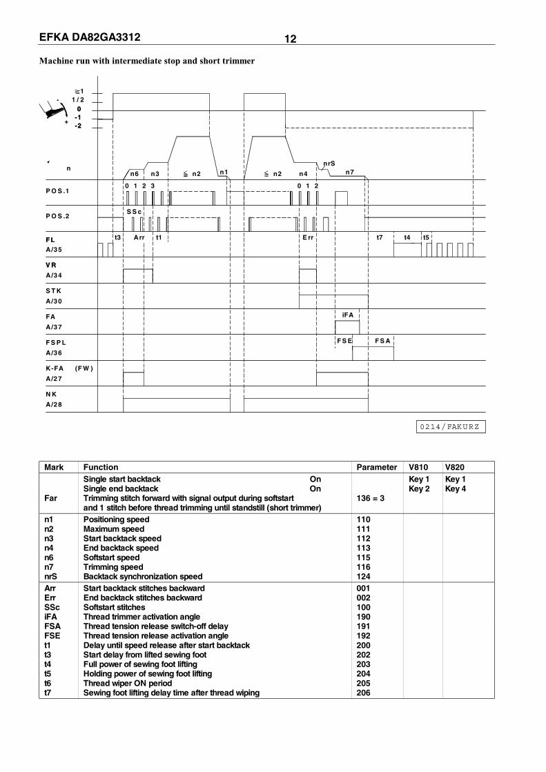
EFKA DA82GA3312 12 Machine run with intermediate stop and short trimmer
A/28
0
S S cP O S .2
A/30
A/35
A/34
S T K
A/27
K-FA
A/37
F S P L
A/36
FA
N K
F LF L
V RV R
(F W )
t3
P O S .1
-
-1-1+
-2-2
n
0 0
1/ 21
t1Arr
n2
1 2 3
n3n6 n1
0214/FAKURZ
E rr
iFA
F S E F S A
t7
nrS
n4n2
0 1 2
n7
t4 t5
Mark Function Parameter V810 V820 Single start backtack On Key 1 Key 1 Single end backtack On Key 2 Key 4 Far Trimming stitch forward with signal output during softstart 136 = 3 and 1 stitch before thread trimming until standstill (short trimmer) n1 Positioning speed 110 n2 Maximum speed 111 n3 Start backtack speed 112 n4 End backtack speed 113 n6 Softstart speed 115 n7 Trimming speed 116 nrS Backtack synchronization speed 124 Arr Start backtack stitches backward 001 Err End backtack stitches backward 002 SSc Softstart stitches 100 iFA Thread trimmer activation angle 190 FSA Thread tension release switch-off delay 191 FSE Thread tension release activation angle 192 t1 Delay until speed release after start backtack 200 t3 Start delay from lifted sewing foot 202 t4 Full power of sewing foot lifting 203 t5 Holding power of sewing foot lifting 204 t6 Thread wiper ON period 205 t7 Sewing foot lifting delay time after thread wiping 206

EFKA DA82GA3312 13 Machine run with intermediate stop and thread clamp On
A/28
A/30
P O S .2
A/35
A/34
S T K
A/36
A/27
F S P L
A/37
F K
F W
FA
F LF L
V RV R
t3
P O S .1
- 0 0
-2-2-1-1
n
+
11/ 2
K1
K1K2
K2
t1Arr
nF E n3
3210
n2 n1
0214/LAUF- FK
F S A
E rr
iFA
F S E
n4
1
n2
0
n7
2
t6
t4t7 t5
Mark Function Parameter V810 V820 Single start backtack On Key 1 Key 1 Single end backtack On Key 2 Key 4 FkL Thread clamp 154 = 1 n1 Positioning speed 110 n2 Maximum speed 111 n3 Start backtack speed 112 n4 End backtack speed 113 n7 Trimming speed 116 nFE Thread pull-in speed fixed Arr Start backtack stitches backward 001 Err End backtack stitches backward 002 k1 Increments up to thread clamp enable (signal 1) 155 k1- Increments up to thread clamp disable (signal 1) 156 k2 Increments up to thread clamp enable (signal 2) 157 k2- Increments up to thread clamp disable (signal 2) 158 iFA Thread trimmer activation angle 190 FSA Thread tension release switch-off delay 191 FSE Thread tension release activation angle 192 t1 Delay until speed release after start backtack 200 t3 Start delay from lifted sewing foot 202 t4 Full power of sewing foot lifting 203 t5 Holding power of sewing foot lifting 204 t6 Thread wiper ON period 205 t7 Sewing foot lifting delay time after thread wiping 206

EFKA DA82GA3312 14 Trimming from intermediate stop
A/28
P O S .2
A/35
A/30
A/34
S T K
A/27
F S P L
A/37
A/36
F W
N K
FA
V R
F L t3
-
P O S .1
0
-2-1
n
+
11/ 2
S S c
Arr t1
n3n6
0 1 2 3
n2 n1
0214/FAZW
E rrt3
iFA
F S AF S E
t6
n4
210 3
n7
t7 t5t4
Mark Function Parameter V810 V820 Basic position 2 On Key 4 Key 7 Single start backtack On Key 1 Key 1 Single end backtack On Key 2 Key 4 SSt Softstart 134 = ON n1 Positioning speed 110 n2 Maximum speed 111 n3 Start backtack speed 112 n4 End backtack speed 113 n6 Softstart speed 115 n7 Trimming speed 116 Arr Start backtack stitches backward 001 Err End backtack stitches backward 002 SSc Softstart stitches 100 iFA Thread trimmer activation angle 190 FSA Thread tension release switch-off delay 191 FSE Thread tension release activation angle 192 t1 Delay until speed release after start backtack 200 t3 Start delay from lifted sewing foot 202 t4 Full power of sewing foot lifting 203 t5 Holding power of sewing foot lifting 204 t6 Thread wiper ON period 205 t7 Sewing foot lifting delay time after thread wiping 206 tSr Stop time for ornamental backtack 210

EFKA DA82GA3312 15 Seam end by stitch counting
3
FA
F W
A/28
N K
A/27
A/37
A/36
F S P L
A/30
F LA/35
S T K
V R
A/34
t3
+
n
P O S .1
P O S .2
-
-2
0
-1 0
11/ 2
S tc E rr
n1 2
1 0 2 0
n4
1 2
0214/ENDEZAE
t4
F S E
E rv
iFA
F S A
t6
t7
3
n7
1 2
t5
Mark Function Parameter V810 V820 Stitch counting On --- Key 2 Double end backtack On Key 2 Key 4 n4 End backtack speed 113 n7 Trimming speed 116 n12 Stitch counting speed 118 Err End backtack stitches backward 002 Erv End backtack stitches forward 003 Stc Stitches of the seam with stitch counting 007 iFA Thread trimmer activation angle 190 FSA Thread tension release switch-off delay 191 FSE Thread tension release activation angle 192 t3 Start delay from lifted sewing foot 202 t4 Full power of sewing foot lifting 203 t5 Holding power of sewing foot lifting 204 t6 Thread wiper ON period 205 t7 Sewing foot lifting delay time after thread wiping 206

EFKA DA82GA3312 16 End sensing by light barrier
LS
A/34
A/35
A/30
S T K
A/28
A/27
F S P L
A/37
A/36
F W
N K
F L
V R
FA
t3
P O S .2
P O S .1
-
n
-2-1 0
11/ 2
+
E rrLS
n2 n5 n4
0 3 4 5 6 1 2
0214/ENDELS
F S AF S E
iFA
drd
n7
3
ird
t5
t6 t7
t4
Mark Function Parameter V810 V820 Single end backtack On Key 2 Key 4 LS Light barrier On 009 = ON LSd Light barrier covered/uncovered 131 = ON Frd Reversion 182 = ON n2 Maximum speed 111 n3 Start backtack speed 112 n5 Speed after light barrier sensing 114 n7 Trimming speed 116 Err End backtack stitches backward 002 LS Light barrier compensating stitches 004 ird Number of reversion increments 180 drd Reversion switch-on delay 181 iFA Thread trimmer activation angle 190 FSA Thread tension release switch-off delay 191 FSE Thread tension release activation angle 192 t3 Start delay from lifted sewing foot 202 t4 Full power of sewing foot lifting 203 t5 Holding power of sewing foot lifting 204 t6 Thread wiper ON period 205 t7 Sewing foot lifting delay time after thread wiping 206

EFKA DA82GA3312 17 Machine run with ornamental backtack (parameter 217 = OFF)
n2
N K
A/28
0
P O S .2
A/35
A/34
A/30
A/37
F S P L
A/36
A/27
FA
F W
S T K
F L
V R
t3
-
P O S .1
-2-1 0
n
+
1/ 21
S Av tS r S Ar S ArtS r
n1
3
n3 n3n1
321 1 2
n3
1 2 3
0214/LAUFZVR
3
F S E
S E rtS r S E vtS r
n4
1
n1 n4n1
2132
iFA
F S A
t6
n7
Mark Function Parameter V810 V820 SrS Ornamental backtack On 135 = ON SLU Normal stitch length On 137 = ON Zrv Last counted forward section during ornamental backtack at the start 215 = ON of the seam On SSL Stop time after the ornamental backtack at the start of the seam Off 217 = OFF n1 Positioning speed 110 n2 Maximum speed 111 n3 Start backtack speed 112 n4 End backtack speed 113 n7 Trimming speed 116 SAv Number of stitches for start ornamental backtack forward 080 SAr Number of stitches for start ornamental backtack backward 081 SEr Number of stitches for end ornamental backtack backward 082 SEv Number of stitches for end ornamental backtack forward 083 iFA Thread trimmer activation angle 190 FSA Thread tension release switch-off delay 191 FSE Thread tension release activation angle 192 t3 Start delay from lifted sewing foot 202 t6 Thread wiper ON period 205 tSr Stop time for ornamental backtack 210
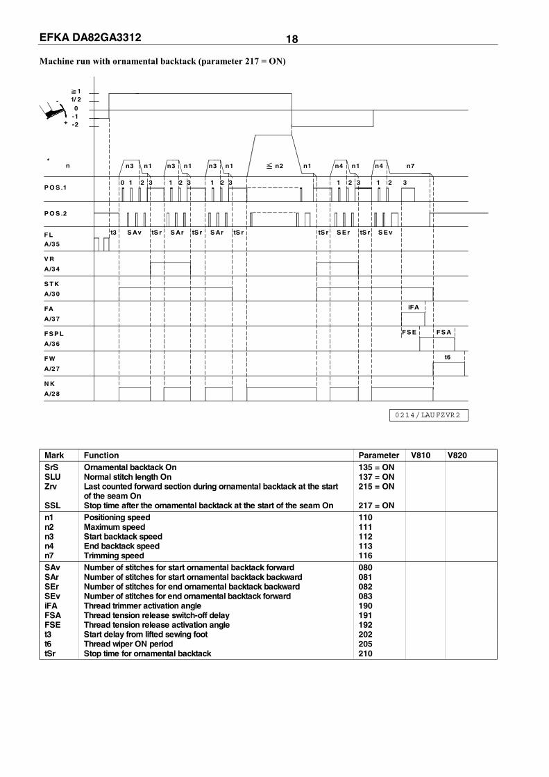
EFKA DA82GA3312 18 Machine run with ornamental backtack (parameter 217 = ON)
N K
A/28
0
P O S .2
A/35
A/34
A/30
A/37
F S P L
A/36
A/27
FA
F W
S TK
F L
V R
t3
-
P O S .1
-2-1 0
n
+
1/ 21
S Av tS r S Ar S ArtS r tS r
3
n1n3 n3n1
321 1 2 3
n1n3
1 2
0214/LAUFZVR2
S E vtS r S E r tS r
n1n2 n4
1
n4n1
132
t6
F S AF S E
iFA
32
n7
Mark Function Parameter V810 V820 SrS Ornamental backtack On 135 = ON SLU Normal stitch length On 137 = ON Zrv Last counted forward section during ornamental backtack at the start 215 = ON of the seam On SSL Stop time after the ornamental backtack at the start of the seam On 217 = ON n1 Positioning speed 110 n2 Maximum speed 111 n3 Start backtack speed 112 n4 End backtack speed 113 n7 Trimming speed 116 SAv Number of stitches for start ornamental backtack forward 080 SAr Number of stitches for start ornamental backtack backward 081 SEr Number of stitches for end ornamental backtack backward 082 SEv Number of stitches for end ornamental backtack forward 083 iFA Thread trimmer activation angle 190 FSA Thread tension release switch-off delay 191 FSE Thread tension release activation angle 192 t3 Start delay from lifted sewing foot 202 t6 Thread wiper ON period 205 tSr Stop time for ornamental backtack 210

EFKA DA82GA3312 19 Machine run with high lift for walking foot
t3
P O S .1
F LA/35
N K
A/32
A/34
H P
H P
P O S .2
n
-2-1 0
11/ 2-
+
0
n2
hP v
1 2 3 4 75 6 8
n10
chP
9
n2
thP
n1
t2
0214/LAUFH UB
t4 t5
Mark Function Parameter V810 V820 hPr High lift for walking foot operational mode not stored 138 = OFF Fc6 Key on socket D/6 “function: high lift for walking foot” 149 = 1 n1 Positioning speed 110 n2 Maximum speed 111 n10 High lift walking speed 117 thP High lift walking speed run-out time 152 chP Minimum high lift walking speed 184 hPv High lift for walking foot switch-on delay 189 t2 Delay of sewing foot lifting with pedal in pos. -1 201 t3 Start delay from lifted sewing foot 202 t4 Full power of sewing foot lifting 203 t5 Holding power of sewing foot lifting 204

EFKA DA82GA3312 20 4 List of Parameters 4.1 Operator Level
Parameter Designation Unit Limits Preset for Ind.
max min 100Ω 220Ω 680Ω 1000Ω 000 Arv Number of stitches of start backtack stitches 254 0 2 3 2 2 A forward 001 Arr Number of stitches of start backtack stitches 254 0 4 3 2 4 A backward 002 Err Number of stitches of end backtack stitches 254 0 3 2 2 3 A backward 003 Erv Number of stitches of end backtack stitches 254 0 3 3 5 3 A forward 004 LS Light barrier compensating stitches stitches 254 0 4 4 4 4 A (for long stitches) 005 LSF Number of stitches of the light barrier filter stitches 254 0 0 0 0 0 A for knitted fabrics 006 LSn Number of light barrier seams 15 1 1 1 1 1 A 007 Stc Number of stitches for the seam with stitch stitches 254 0 10 10 10 10 A counting 008 -F- A parameter from the technician level is assigned to 5 1 2 1 2 2 A key 9 on the V820 control panel 1 = Softstart On/Off 2 = Ornamental backtack On/Off 3 = High lift for walking foot operational mode stored = On / operational mode not stored = Off 4 = Needle cooling On/Off (only if parameter 185 = 1) 5 = Reversion On/Off 009 LS Light barrier On/Off ON/OFF OFF OFF OFF OFF A 010 cLS Light barrier compensating stitches stitches 254 0 8 8 8 8 A (for normal stitch length) 013 FA Thread trimmer On/Off ON/OFF ON ON ON ON A 014 FW Thread wiper On/Off ON/OFF ON OFF OFF OFF A 015 StS Stitch counting On/Off ON/OFF OFF OFF OFF OFF A 080 SAv Number of start ornamental backtack stitches 254 0 3 3 2 3 A stitches forward 081 SAr Number of start ornamental backtack stitches 254 0 3 3 2 3 A stitches backward 082 SEr Number of end ornamental backtack stitches 254 0 3 3 2 3 A stitches backward 083 SEv Number of end ornamental backtack stitches 254 0 3 3 2 3 A stitches forward 085 cFw Number of stitches for thread monitor Parameter 195 = 1...3 2540 0 0 0 0 0 A Parameter 195 = 4 9990 0 0 0 0 0 A If parameter 195 = 4, the following functions will be activated upon pressing the appropriate key: >1 sec. = Thread monitor function is deactivated. <1 sec. = Counter is set to preset value. 090 wAR Repetitions of double start backtacking 254 0 0 0 0 0 H 091 wER Repetitions of double end bakctacking 254 0 0 0 0 0 H 092 cb1 Number of catch backtacking stitches stitches 254 0 0 0 0 0 H forward 093 cb2 Number of catch backtacking stitches stitches 254 0 0 0 0 0 H backward
Note:
At the operator level, the parameter number (F-xxx) is not shown on the display, but the abbreviation (e. g. Arv) and the actual value (e. g. 002 for 2 stitches).

EFKA DA82GA3312 21 4.2 Technician Level
Code no. 1907 with control panel operation
Parameter Designation Unit Limits Preset for Ind.
max min 100Ω 220Ω 680Ω 1000Ω 100 SSc Number of softstart stitches stitches 254 0 1 1 1 1 C 101 t15 Switch-on delay for the stitch regulator ms 255 0 0 0 0 0 E during start backtack 102 t16 Switch-off delay for the stitch regulator ms 255 0 0 0 0 0 E during start backtack 103 t17 Switch-on delay for the stitch regulator ms 255 0 0 0 0 0 E during end backtack 104 t18 Switch-off delay for the stitch regulator ms 255 0 0 0 0 0 E during end backtack 110 n1 Positioning speed RPM 390 70 150 100 150 150 A 111 n2- Upper limit setting range of the maximum RPM 5000 n2_ 4000 900 1700 3500 F speed 112 n3 Start backtacking speed RPM 3000 200 1200 400 800 1200 A 113 n4 End backtacking speed RPM 3000 200 1200 400 800 1200 A 114 n5 Speed after light barrier sensing RPM 3000 200 1200 400 800 1200 A 115 n6 Softstart speed RPM 2500 70 400 250 400 400 A 116 n7 Trimming speed RPM 500 70 150 100 150 150 A 117 n10 High lift walking speed RPM 2500 400 2000 400 800 2000 A = speed limitation (DB2000) 118 n12 Automatic speed for stitch counting RPM 5000 400 1200 400 800 1200 A according to setting of parameter 141 119 nSt Speed stage graduation 3 1 1 1 1 1 A 1 = linear 2 = slightly progressive 3 = highly progressive 120 nnk Whenever this speed is exceeded, RPM 5000 0 3000 3000 3000 3000 E needle cooling is activated, if parameter 185 is set to “3“ 121 n2_ Lower limit setting range of the maximum RPM n2- 400 400 400 400 400 A speed 123 tnS End backtack synchronization time ms 500 0 40 0 0 40 A 124 nrS End backtack synchronization speed RPM 3000 100 500 400 800 500 A 125 n2A Start backtack speed 2 RPM 3000 200 600 600 600 600 E (only if parameter 284 = ON) 126 n2E End backtack speed 2 RPM 3000 200 600 600 600 600 E (only if parameter 284 = ON) 127 AkS Acoustic signal during machine run blockage or 3 0 0 0 0 0 E thread monitor (pa. 195 = 4 and according to the setting of the number of stitches by means of parameter 085) 0 = Acoustic signal Off 1 = Acoustic signal from stop after execution of stitches to pressing key 8. 2 = Drive stops after execution of stitches. Sewing is possible up to the seam end. After that the acoustic signal is issued until key 8 is pressed. 3 = Drive stops after execution of stitches, and the acoustic signal is issued 5 times. Sewing is possible up to the seam end. After that the acoustic signal is issued until key 8 is pressed. 128 Asd Start delay, when command “start” is ms 2000 0 0 0 0 0 A given by covering the light barrier (only if parameter 129 = ON)

EFKA DA82GA3312 22 Technician Level
Code no. 1907 with control panel operation
Parameter Designation Unit Limits Preset for Ind.
max min 100Ω 220Ω 680Ω 1000Ω 129 ALS Automatic start by light barrier On/Off: ON/OFF OFF OFF OFF OFF A machine start by covering the light barrier, without having heeled the pedal back to the basic position. Additional prerequisites: - Parameter 132 = ON - Function “light barrier sensing” enabled on the control panel - Initiation of the first “normal” seam section (pedal in the basic position) - Cover light barrier - Press pedal forward - Keep pedal pressed forward Deactivate this function by heeling the pedal back to the basic position. 130 LSF Light barrier filter for knitted fabrics On/Off ON/OFF OFF OFF OFF OFF A 131 LSd OFF = Light barrier sensing “covered” ON/OFF ON ON ON ON A ON = Light barrier sensing “uncovered” 132 LSS OFF = Machine start possible with light ON/OFF ON ON ON ON A barrier uncovered or covered. ON = Machine start blocked with light barrier uncovered if pa. 131 = ON. Machine start blocked with light barrier covered if pa. 131 = OFF. 133 LSE Thread trimming operation, when ON/OFF ON ON ON ON A completing the seam after light barrier sensing On/Off 134 SSt Softstart On/Off ON/OFF ON ON ON ON A 135 SrS Ornamental backtack On/Off ON/OFF OFF OFF OFF OFF A 136 FAr Power transistor function on A/27 (functions: 4 0 0 0 1 0 E thread trimmer, thread wiper and short trimmer) 0 = Trimming stitch forward and thread wiper function On 1 = Trimming stitch backward and thread wiper function On 2 = Trimming stitch forward with short trimmer signal On. Thread wiper function Off. 3 = Trimming stitch forward with signal for stitch length reduction during softstart and signal for short trimmer On. Thread wiper function Off. 4 = Trimming stitch forward with signal for stitch length reduction during softstart. Thread wiper function Off. 137 SLU Stitch length during backtack ON/OFF ON OFF OFF OFF A OFF= long stitches ON = normal stitches 138 hPr OFF = High lift for walking foot ON/OFF OFF OFF OFF OFF A operational mode not stored ON = High lift for walking foot operational mode stored 139 nIS Display of machine speed On/Off ON/OFF OFF OFF OFF OFF A 140 nh1 Mode “key needle up/down” on socket A/6 6 1 1 2 2 1 E 1 = Needle up 2 = Needle up/down 3 = Single stitch 4 = Single stitch with stitch length switching 5 = Needle up if outside position 2 6 = Machine stop in position 2 and sewing foot up. Machine run blockage symbol blinking on V820 and “stop” on V810, respectively. After power Off/On the drive is ready again.

EFKA DA82GA3312 23 Technician Level
Code no. 1907 with control panel operation
Parameter Designation Unit Limits Preset for Ind.
max min 100Ω 220Ω 680Ω 1000Ω 141 SGn Speed status for the seam with stitch counting 3 0 1 1 1 1 A 0 = Speed controllable by the pedal up to the set maximum speed (parameter 111) 1 = Fixed speed (parameter 118) without influence by the pedal (machine stop by pressing the pedal to the basic position) 2 = Limited speed controllable by the pedal up to the set limit (parameter 118) 3 = At fixed speed (parameter 118) can be interrupted by full heelback 142 SFn Speed status for the free seam and for the seam 3 0 0 0 0 0 A with light barrier 0 = Speed controllable by the pedal up to the set maximum speed (parameter 111) 1 = Fixed speed (parameter 118) without influence by the pedal (machine stop by pressing the pedal to the basic position) 2 = Limited speed controllable by the pedal up to the set limit (parameter 118) 3 = At fixed speed (parameter 118) can be interrupted by full heelback (only in conjunction with light barrier On, otherwise like setting 0) 143 mnF Mode “key speed limitation” (DB2000) 2 1 1 1 1 1 A on socket A/9 1 = Speed n10 limited (DB2000) 2 = Speed n10 fixed 144 nh2 Mode “key needle up/down” on socket D/1 6 1 1 1 1 1 E 1 = Needle up 2 = Needle up/down 3 = Single stitch 4 = Single stitch with stitch length switching 5 = Needle up if outside position 2 6 = Machine stop in position 2 and sewing foot up. Machine run blockage symbol blinking on V820 and “stop” on V810, respectively. After power Off/On the drive is ready again. 145 StL Normal/long stitches with/without speed limitation. 3 1 1 1 1 1 A Key on socket D/2. 1 = Normal/long stitches without speed limitation 2 = Normal/long stitches without speed limitation (DB2000) 3 = Normal/long stitches without speed limitation (DB3000) 146 mFd Function of the key on socket D/4. 4 1 3 3 3 3 A 1 = Sewing foot pressure reduction with speed limitation (DB2000) 2 = Sewing foot pressure reduction with speed limitation (DB3000) 3 = Roller 4 = Sewing foot pressure reduction inverted relative to the sewing foot 147 Fc3 Function of the key on socket D/3 3 1 1 1 1 1 F 1 = Thread tension reduction 2 = Backtack suppresion/recall 3 = Roller 148 Fc5 Function of the key on socket D/5 2 1 2 2 2 2 A 1 = Speed limitation (DB3000) 2 = Intermediate backtack

EFKA DA82GA3312 24 Technician Level
Code no. 1907 with control panel operation
Parameter Designation Unit Limits Preset for Ind.
max min 100Ω 220Ω 680Ω 1000Ω 149 Fc6 Function of the key on socket D/6 3 1 1 1 1 1 F 1 = Hight lift for walking foot 2 = Thread tension reduction 3 = Roller 152 thP Run-out time of the high lift walking speed ms 500 80 100 100 100 100 A after disabling the high lift for walking foot 153 brt Braking power at machine standstill 50 0 6 6 6 6 A 154 FkL Thread clamp function 7 0 0 0 0 0 F 0 = Thread clamp Off 1 = Thread clamp function when using the values of parameters 155...158 2...7 = Preset values (see table in the instruction manual) The thread clamp functions are performed at a fixed speed of 250 RPM! 155 k1 Increments up to enabling of the thread incr. 500 0 100 100 100 100 A clamp (signal 1) 156 k1- Increments up to disabling of the thread incr. 500 0 200 200 200 200 A clamp (signal 1). This parameter setting value must not be lower than that of parameter 155. 157 k2 Increments up to enabling of the thread incr. 500 0 0 0 0 0 A clamp (signal 2) 158 k2- Increments up to disabling of the thread incr. 500 0 0 0 0 0 A clamp (signal 2). This parameter setting value must not be lower than that of parameter 157. 161 drE Direction of motor rotation 1 0 1 1 1 1 A 0 = Clockwise rotation 1 = Counterclockwise rotation 170 Sr1 Setting the reference position: ****) A - Press the E key. - Press the >> key. - Position 0 = Needle point at the height of the needle plate, from downward movement of the - needle in the direction of rotation of the motor - shaft. 171 Sr2 Setting the needle positions: ****) Press key E. Press key >>. 1 = Position 1 (leading edge) 510 0 170 150 160 60 C Press key E. 2 = Position 2 (leading edge) 510 0 440 422 440 466 C Press key E. 1A = Position 1 (trailing edge) 510 0 250 250 210 200 A Press key E. 3 = Position 3 no function 510 0 0 0 0 0 A Press key E. 3A = Position 3 no function 510 0 0 0 0 0 A (for changing the values turn handwheel or press key +/-) Press key P twice. Settings are completed! 172 Sr3 Display on the V810 control panel: Pos. 1 to 1A (lefthand arrow above key 4 On) Pos. 2 to 2A (righthand arrow above key 4 On) Function active only after sewing has been started once! 172 Sr3 Display on the V820 control panel: Pos. 1 to 1A (lefthand arrow above key 7 On) Pos. 2 to 2A (righthand arrow above key 7 On) Function active only after sewing has been started once!
****) For more detailed instructions see instruction manual!

EFKA DA82GA3312 25 Technician Level
Code no. 1907 with control panel operation
Parameter Designation Unit Limits Preset for Ind.
max min 100Ω 220Ω 680Ω 1000Ω 173 Sr4 Checking of the signal outputs and inputs using the V810/V820 control panels - Select the desired output using the +/- key - Activate the selected output using the >> key 01 = Backtacking on socket A/34 02 = Sewing foot lift on socket A/35 03 = Thread trimmer on socket A/37 04 = Thread wiper on socket A/27 05 = Stitch length switching on socket A/30 06 = Thread tension release on sockets A/36, B/5, C/5 07 = Thread tension reduction on socket A/20 08 = Needle cooling on socket A/28 09 = Motor running on sockets A/26, B/6 10 = High lift for walking foot on socket A/32 11 = No assignment on socket A/22 12 = LED for needle up/down on socket D/9 13 = LED for long stitch on socket D/10 14 = Thread clamp on socket A/18 15 = LED for high lift for walking foot on socket A/31 16 = LED for righthand thread monitor on socket A/25 17 = LED for sewing foot pressure reduction on socket D/12 18 = LED for thread tension reduction/backtack suppression/recall on socket D/11 19 = Sewing foot pressure reduction on socket A/21 20 = LED for lefthand thread monitor on socket A/23 21 = Flip-flop on socket C/6 22 = LED for high lift limitation/thread tension reduction on socket D/14 23 = LED for backtack suppression/recall on socket A/24 24 = LED for speed limitation 3000 / intermediate backtack on socket D/13 (effective only in conjunction with the key on socket D/5) 25 = LED for long stitch on socket A/29 26 = No assignment on socket A/17 27 = No assignment on socket A/16 28 = Roller feed on socket A/15 OFF/ON = By actuating the switches connected to the control, the function of these switches is checked and ON/OFF is displayed on the V810/V820 control panels 179 Sr5 V820 control panel display: Control program number with index and identification number. V810 control panel display: Upon pressing the “<<” key, data will be displayed in succession. 180 ird Number of reversing increments incr. 400 20 40 40 30 90 C 181 drd Switch-on delay of reverse motor rotation ms 990 0 0 0 0 0 A 182 Frd Reverse motor rotation On/Off ON/OFF OFF OFF OFF OFF A 183 dnk Switch-off delay of needle cooling after ms 2550 0 2500 2500 2500 2500 E stop or falling below the switch speed (parameter 120) 184 chP Minimum number of stitches for high lift stitches 100 0 0 0 0 0 A for walking foot

EFKA DA82GA3312 26 Technician Level
Code no. 1907 with control panel operation
Parameter Designation Unit Limits Preset for Ind.
max min 100Ω 220Ω 680Ω 1000Ω 185 Fnk Function of the output “needle cooling” 3 1 1 1 1 1 E 1 = Needle cooling 2 = Reserved for option 3 = Needle cooling depending on speed (the switch speed can be set using pa. 120) 186 ctw Stitches until roller lowering stitches 100 0 10 10 10 10 A 187 Stn Stitch length in the next seam (after the thread 3 1 1 1 1 1 A trimming operation) 1 = The selected stitch legth remains On. 2 = Switch to long stitches after thread trimming. 3 = Switch to normal stitches after thread trimming. 188 hP Minimum speed level for high lift for walking foot 21 1 A Maximum speed level for high lift for walking foot 21 1 A Assignment of maximum speed (parameter 111) and minimum speed (parameter 117 = high lift walking speed) to the 21 speedomat levels. Display example: 2740 05 11 19 05 = Display of the level up to which the maximum speed is effective. 19 = Display of the level up to which the minimum speed is effective. 11 = Display of the level set on the speedomat (potentiometer). 2740 = Corresponding speed See instruction manual on how to change the setting! 189 hPv High lift for walking foot switch-on delay ms 2550 0 0 0 0 0 A 190 iFA Activation angle of the thread trimmer incr. 450 0 450 450 450 80 E (1 increment corresponds to 0.7°) Set to 180 with series N291 and 8967! 191 FSA Thread tension release switch-off delay ms 990 0 50 50 50 50 A 192 FSE Angle of thread tension release switch–on incr. 450 0 0 0 210 260 C delay (i increment corresponds to 0.7°) 193 tFA Thread trimmer stop time ms 500 0 0 0 0 30 A 194 FAE Angle of thread timmer switch-on delay incr. 450 0 0 0 0 0 A 195 rFW Thread monitor mode 4 0 0 0 0 0 A 0 = No thread monitor function. 1 = Model 270 or short seams. Without stop, sewing foot down after thread trimming. 2 = Model 767/N291. With stop, sewing foot up after thread trimming. 3 = Model 767/N291. With stop, sewing foot down after thread trimming. 4 = With thread monitor stitch counting (max. 9990 stitches) Number of stitches according to setting of parameter 085.

EFKA DA82GA3312 27 Technician Level
Code no. 1907 with control panel operation
Parameter Designation Unit Limits Preset for Ind.
max min 100Ω 220Ω 680Ω 1000Ω 196 kFn 0 = Thread tension release and thread tension 3 0 0 0 0 0 A reduction “Off” during sewing foot lifting. 1 = Thread tension release and thread tension reduction “On” during sewing foot lifting in the seam. 2 = Thread tension release and thread tension reduction “On” during sewing foot lifting after thread trimming. 3 = Thread tension release and thread tension reduction “On” during sewing foot lifting in the seam and after thread trimming. If parameter 147 = 1 (key on socket D/3) or parameter 149 = 2 (key on socket D/6), thread tension reduction can be enabled at any time. The operational mode of the keys is stored. 197 kFh 0 = Coupling thread tension reduction with high 3 0 0 0 0 0 A lift for walking foot and speedomat Off. 1 = Thread tension reduction is disabled and high lift for walking foot enabled using the key on socket A/7. The speedomat has no effect. 2 = When reaching the high lift walking speed by adjusting the speedomat, thread tension reduction is disabled. The key on socket A/7 has no effect. 3 = When reaching the high lift walking speed by adjusting the speedomat, thread tension reduction is disabled. The key on socket A/7 works as with setting 1. If parameter 147 = 1 (key on socket D/3) or parameter 149 = 2 (key on socket D/6), thread tension reduction can be enabled at any time. The operational mode of the keys is stored. 198 mmL 1 = Motor running 3 1 2 2 2 2 H 2 = 2nd thread tension release n > Param. 120, FSPL2 = On n < Param. 120, FSPL2 = Off 3 = 2nd thread tension release n < Param. 120, FSPL2 = On n > Param. 120, FSPL2 = Off

EFKA DA82GA3312 28 4.3 Supplier Level
Code no. 3112 with control panel operation
Parameter Designation Unit Limits Preset for Ind.
max min 100Ω 220Ω 680Ω 1000Ω 200 t1 Delay until speed release after start ms 500 0 50 50 50 50 A backtack 201 t2 Sewing foot lift switch-on delay with half ms 500 20 80 80 80 80 A heelback 202 t3 Start delay after disabling the sewing foot ms 500 0 80 80 120 80 C lift signal 203 t4 Time of full power of sewing foot lifting ms 600 0 200 200 200 200 A 204 t5 Holding power for sewing foot lifting 3 3 3 3 A Stages 0, 1...7 Stage 0 100% high holding power Stage 1 12.5% low holding power Stage 7 87.5% 205 t6 Thread wiper time ms 500 0 100 100 100 100 A 206 t7 Delay from end of thread wiper until ms 800 0 30 30 30 30 A sewing foot lifting On 207 br1 Braking effect when modifying the preset value ≤ 4 stages Preset value if parameter 225 = 0 255 1 25 25 25 25 A Preset value if parameter 225 = 1 255 1 25 25 25 25 A Preset value if parameter 225 = 2 255 1 25 25 25 25 A Preset value if parameter 225 = 3 255 1 10 10 10 10 A 208 br2 Braking effect when modifying the preset value ≥ 5 stages Preset value if parameter 225 = 0 255 1 60 60 60 60 A Preset value if parameter 225 = 1 255 1 60 60 60 60 A Preset value if parameter 225 = 2 255 1 60 60 60 60 A Preset value if parameter 225 = 3 255 1 25 25 25 25 A 210 tSr Stop time for switching the stitch regulator ms 500 0 100 270 150 100 C in the ornamental backtack 212 t10 Time of full power of backtacking ms 600 0 200 200 200 200 A 213 t11 Holding power for backtacking 4 4 4 4 A Stages 0, 1...7 Stage 0 100% high holding power Stage 1 12.5% low holding power Stage 7 87.5% 215 Zrv OFF = Last counted forward section in ON/OFF ON ON ON ON A the start backtack OFF ON = Last counted forward section in the start backtack ON 216 FLS OFF = Fast disabling of sewing foot lift ON/OFF ON ON ON ON A Off ON = Fast disabling of sewing foot lift On 217 SSL OFF = Stop time after the ornamental ON/OFF OFF OFF OFF OFF G backtack at the start of the seam Off ON = ,Stop time after the ornamental backtack at the start of the seam On, if parameter 135 / 137 = ON 220 ALF Accelerating power of the drive Preset value if parameter 225 = 0 255 5 32 32 32 32 A Preset value if parameter 225 = 1 255 5 32 32 32 32 A Preset value if parameter 225 = 2 255 5 32 32 32 32 A Preset value if parameter 225 = 3 255 5 15 15 15 15 A

EFKA DA82GA3312 29 Supplier Level
Code no. 3112 with control panel operation
Parameter Designation Unit Limits Preset for Ind.
max min 100Ω 220Ω 680Ω 1000Ω 225 rEG 0 = Normal machines 3 0 0 2 3 0 C 1 = Medium-duty machines 2 = Heavy-duty machines 3 = Machine models 4180 and 4280 The preset values of parameters 207, 208 and 220 change depending on the setting of parameter 225. See respective parameters. 231 Sn1 Execution of the 1st stitch after power On ON/OFF OFF OFF OFF OFF A at positioning speed. 260 PLc Time interval which can be varied by ON/OFF OFF OFF OFF OFF A means of the number of stitches performed after sewing foot lowering until roller lowering in the seam On/Off (setting by means of parameter 186). OFF = Time interval which can be varied by the number of stitches performed Off ON = Time interval which can be varied by the number of stitches performed On 261 FLk 0 = Roller not coupled with sewing foot lift or 3 0 1 1 1 1 A backtack 1 = Lift roller with sewing foot lift or backtack 2 = Lift roller with sewing foot lift 3 = Lift roller with backtack 262 hPt 0 = Roller remains lowered when enabling 1 0 0 0 0 0 A high lift for walking foot. 1 = Roller is lifted when enabling high lift for walking foot. 275 Std Seam suppression when 0 stitches have been set 1 0 0 0 0 0 A 276 dkn 0 = Correction seam Off 2 0 0 0 0 0 A 1 = Correction seam On 2 = Interruption of seam or pattern by thread trimming 277 nFS Select: Switch from one seam or pattern to the 1 0 0 0 0 0 E next 0 = Switch from one seam to the next 1 = Switch from one pattern to the next 280 SEL Display of the select resistor values (socket A/1-4) 1000 100 100 220 680 1000 E for the following machine series: 100Ω = 271 N291, 8967 (set parameter 190 to 180) 220Ω = 204, 205, 221, 266, 366 680Ω = 069, 267, 268, 269, 4180, 4280 1000Ω = 381, 382, 467, 767, 768 281 Pd0 New sewing start after machine run ON/OFF ON ON ON ON A blockage ON = Immediate start OFF = Only with pedal in position 0 (neutral) 282 LoS Functioning of the switch for machine run blockage 1 0 0 0 0 0 A 0 = Make contact (N.O.) 1 = Break contact (N.C.) 283 LSP Function “machine run blockage” 2 0 1 1 1 1 A 0 = Function Off 1 = Blockage 1, without positioning 2 = Blockage 2, with positioning 284 StP Start and end backtack can be interrupted ON/OFF OFF OFF OFF OFF A with pedal in position 0 (neutral) On/Off

EFKA DA82GA3312 30 Supplier Level
Code no. 3112 with control panel operation
Parameter Designation Unit Limits Preset for Ind.
max min 100Ω 220Ω 680Ω 1000Ω 287 dbA Speed limitation (n11) DB3000 for manual 1 0 0 0 0 0 A backtack 0 = Speed limitation Off 1 = Speed limitation On 288 n9 Speed limitation (n9) for manual RPM 3000 200 1200 400 800 1200 A ornamental backtack 289 n11 Speed limitation (n11) DB3000 for RPM 3000 500 3000 400 1700 3000 A manual backtack 291 810 Selection of the slide-in strip number for control 10 1 1 1 1 1 E panel V810 (illustration of slide-in strips see chapter “Slide-in Strips Control Panel V810“). Function of key 4 on the control panel: Strip 1-9 Basic position 1 or 2 Strip 10 Thread trimmer/thread wiper On/Off 293 tF1 Selection of the input function using key (A) 19 0 17 17 17 17 A “F1” on the V810 control panel 0 = No function 1 = Needle up 2 = Needle up/down 3 = Single stitch (basting stitch) 4 = Single stitch with stitch length switching 5 = Needle up if outside position 2 6 = Switch stitch length 7 = Thread tension 8 = Sewing foot pressure 9 = Roller 10 = Speed limitation DB3000 11 = No function 12 = No function 13 = High lift for walking foot operational mode stored/not stored according to setting of parameter 138 14 = No function 15 = No function 16 = Intermediate backtack 17 = Backtack suppression / recall 18 = Coupling the sewing foot with thread tension release (parameter 196 > 0) On/Off 19 = Set thread monitor counting (parameter 195 = 4) 294 tF2 Selection of the input function using key (B) 19 0 1 1 1 1 A “F2” on the V810/V820 control panel Functions of the key as with parameter 293 297 tFL Time monitoring of sewing foot lift sec 250 0 0 0 0 0 C (monitoring off at “0“)

EFKA DA82GA3312 31 5 Error Displays
General Information
On the V810 On the V820 Signification
InF A1 InF A1 Pedal not in neutral position, when turning the machine on
-StoP- blinking Symbol blinking Machine run blockage
InF A3 InF A3 The position to which all position values refer has not been stored (reference position missing)
InF A5 InF A5 Emergency run, identification of an invalid machine select
Programming Functions and Values (Parameters)
On the V810 On the V820 Signification
Returns to the Like V810 + Wrong code number or parameter number input frist digit display InF F1
Serious Condition
On the V810 On the V820 Signification
InF E1 InF E1 After power On, postion transmitter or commutation transmitter defective or connecting cables have been changed by mistake. During machine run or after a sewing operation, only position transmitter defects can be identified.
InF E2 InF E2 Line voltage too low, or time between power off and power on too short.
InF E3 InF E3 Machine blocked or does not reach the desired speed.
InF E4 InF E4 Control disturbed by deficient grounding or loose contact.
Hardware Disturbance
On the V810 On the V820 Signification
InF H1 InF H1 Commutation transmitter cord or frequency converter disturbed.
InF H2 InF H2 Processor disturbed

EFKA DA82GA3312 32 6 Slide-in Strips for the V810 Control Panel
BA B
A
B
6
KL2513
F1
C
F1D
F1
F1
F2
A,B,C,D
9
1 0
F2
7
8
F2
1
F1
F1
F1
F1
5
F2
4
F2
3
F2
2
R

EFKA DA82GA3312 33 For your notes:

EFKA DA82GA3312 34 For your notes:

EFKA DA82GA3312 35 For your notes:

FRANKL & KIRCHNER GMBH & CO KG SCHEFFELSTRASSE 73 – 68723 SCHWETZINGEN – GERMANY PHONE: +49-6202-2020 – FAX: +49-6202-202115 E-mail: [email protected] – http://www.efka.net
OF AMERICA INC. 3715 NORTHCREST ROAD – SUITE 10 – ATLANTA – GEORGIA 30340 PHONE: +1 (770) 457-7006 – FAX: +1 (770) 458-3899 – E-mail: [email protected]
ELECTRONIC MOTORS SINGAPORE PTE. LTD. 67, AYER RAJAH CRESCENT 05-03 – SINGAPORE 139950 PHONE: +65-67772459 – FAX: +65-67771048 – E-mail: [email protected] 4(5)-160605-H (402276 EN)