CONSTRUCTION OF THE WING - Bob Reed's KIS Cruiser · PDF fileWING PAGE WING-1 CONSTRUCTION OF...
30
WING PAGE WING-1 CONSTRUCTION OF THE WING FABRICATING THE WING CRADLES The wing is built inverted in four building jigs or cradles that are fabricated prior to starting any glass work. Buy two sheets of ½ inch particleboard and lay out the patterns as shown. All lines are straight except the saddle curves in the tops for the wing skin. The shape for these cutouts can be obtained from the full size pattern provided with the kit. (Carefully glue the pattern to a piece of 1/8 x 6 x 48 inch duron (good quality masonite) or plywood so it holds shape; then cut out to form a rigid template.) Note that there are 3/16 inch wide slots about 7 inches long in the upper pieces to allow for adjustment in height and angle using bolts and wing nuts. There are also ½ inch wide 2-inch long slots or notches in the cradle area for the spanwise support beams. A saber saw will do a good job of cutting all the slots. Assemble the bases of the cradles with carpenter’s glue and screws or nails. Find space in the shop where the basic wing can be assembled less tips. The size less tips is 4 by 20 feet. Pluck a span-wise chalk line on the floor. Mark Center Line, BL25 left, BL25 right, BL118 left, and BL118 right. Set up the four cradles perpendicular to the span-wise line on the BL25 and BL118 marks. Set the cradles at the same approximate height (such as full down) and level each with a long carpenter’s level or a
-
Upload
trinhkhanh -
Category
Documents
-
view
236 -
download
1
Transcript of CONSTRUCTION OF THE WING - Bob Reed's KIS Cruiser · PDF fileWING PAGE WING-1 CONSTRUCTION OF...

WING PAGE WING-1
CONSTRUCTION OF THE WING
FABRICATING THE WING CRADLES
The wing is built inverted in four building jigs or cradles that are fabricated prior to starting any glass work.
Buy two sheets of ½ inch particleboard andlay out the patterns as shown. All lines arestraight except the saddle curves in the topsfor the wing skin. The shape for these cutoutscan be obtained from the full size patternprovided with the kit. (Carefully glue thepattern to a piece of 1/8 x 6 x 48 inch duron(good quality masonite) or plywood so itholds shape; then cut out to form a rigidtemplate.) Note that there are 3/16 inch wideslots about 7 inches long in the upper piecesto allow for adjustment in height and angleusing bolts and wing nuts. There are also ½inch wide 2-inch long slots or notches in thecradle area for the spanwise support beams.A saber saw will do a good job of cutting allthe slots. Assemble the bases of the cradleswith carpenter’s glue and screws or nails.
Find space in the shop where the basic wing can be assembled less tips. The size less tips is 4 by 20 feet.Pluck a span-wise chalk line on the floor. Mark Center Line, BL25 left, BL25 right, BL118 left, and BL118right. Set up the four cradles perpendicular to the span-wise line on the BL25 and BL118 marks. Set thecradles at the same approximate height (such as full down) and level each with a long carpenter’s level or a
WING PAGE WING-2
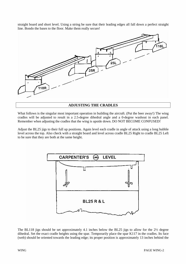
straight board and short level. Using a string be sure that their leading edges all fall down a perfect straightline. Bondo the bases to the floor. Make them really secure!
ADJUSTING THE CRADLES
What follows is the singular most important operation in building the aircraft. (Put the beer away!) The wingcradles will be adjusted to result in a 2.5-degree dihedral angle and a 0-degree washout in each panel.Remember when adjusting the cradles that the wing is upside down. DO NOT BECOME CONFUSED!
Adjust the BL25 jigs to their full up positions. Again level each cradle in angle of attack using a long bubblelevel across the top. Also check with a straight board and level across cradle BL25 Right to cradle BL25 Leftto be sure that they are both at the same height.
The BL118 jigs should be set approximately 4.1 inches below the BL25 jigs to allow for the 2½ degreedihedral. Set the exact cradle heights using the spar. Temporarily place the spar K117 in the cradles. Its face(web) should be oriented towards the leading edge; its proper position is approximately 13 inches behind the

WING PAGE WING-3
leading edge (i.e. over the spanwise support beam notches). Adjust the BL118 cradle heights so that the sparis supported properly.
When you are absolutely satisfied that the cradles are properly adjusted tighten the adjust bolts as tight aspossible and proceed with making the two spanwise support beams so these may be installed between thecradles.
Buy a 4 x 8 sheet of ¾ inch plywood or good quality 1 x 4. Have a friend with a table saw rip 4 pieces about9 inches wide and 8 feet long. One edge must be absolutely straight (or level) from end to end. This will bethe top or upper edge. If neither edge is “true” after ripping it may be because internal stresses were relieved.One way or another it will be necessary to true one edge. Some planing or re-sawing may be required. Theupper edge is to be true within 1/32 inch when checked with a tight string. Don’t worry if the 9-inch height isreduced in this operation but the upper edge must be straight.
From the drawing you will note that each end of the two beams is relieved approximately 2 inches so that anindexing tab extends to assist in assembling the beams to the cradles. Exact dimensions can be determined bythe builder by measuring the distance between cradle notches prior to cutting the beam ends. Note also thatthe exact angles of the ends may best be cut about 2½ degrees off perpendicular to allow for the dihedralangle in the cradle jig set-up.
When satisfied with the fit of the beams glue them in place and add long wood screws through the cradlesand into the beam-ends. Add some glue at the cradle joints and put additional screws throughout the cradleand support pieces as required so there is no chance of slipping. Don’t trust the bolts and wing nuts. Atanytime during wing construction a shift in cradle/jig adjustment could result in a ruined wing.
Make a last minute check of the cradle adjustment before the glue dries. Place the spar in the cradles onemore time. Is the dihedral adjustment correct? Remove the spar and check the washout. Is it exactly zero?The flight qualities of your aircraft will be contingent on this set-up.

WING PAGE WING-4
BUILDING THE WING - STANDARD TANKS
Note: Builders should read this entire section before starting their wing. Persons installing largeengines such as the Lycoming 0-235 who require the larger fuel tank configuration must also read thesection “Building the Wing - Large Fuel Tanks” before starting.
WARNING -- Don’t forget that all the premolded parts have peel ply on the inside. Removethe peel from a part when it is needed. Don’t forget that failure to remove peel ply will resultin catastrophic structural failure in flight.
There is a bit of work that must be done to complete the spar (K13). Measure its length. You will find that itis about 244 inches long. In the spanwise middle you will find a vertical line that denotes center. Make thisline easier to see with a sharp felt tip pen. There should be about 122 inches on each side. Looking at the facemark the following butt lines left and right: 15, 24, 45, 66, 96, and 120. Measure these locations directlyalong a line that would fall along the center of the spar face. Don’t worry about the little bit of error inducedby the dihedral. Draw a line on the face (web) of the spar at each location; it should be perpendicular to thespar cap and go from the top edge to the bottom.
Using a bright light behind the spar web, find the aluminum reinforcement plates that are centered atapproximately BL15 left and right. Mark their location in the spar structure. These are the main attach pointsfor the wing. During assembly of the wing to the fuselage you will be required to drill through these blocksand be near to their centers. If you find that the centers are not within plus or minus ¾ inch of BL15 call thefactory for instructions.
The factory method of fabricating the spar results in the flanges being about 1/4 inch oversize. The onlyproblem occurs where the ribs interface where the spar closure goes. The flange widths must be exactly 2½inches in these areas. Scribe lines for trimming to 2½ inch width for 2 inches each side of the rib locations(24, 45, 66, 96, and 120). Scribe a 2½ trim line from 24 left to 24 right. Remember to scribe both the upperand lower flanges to width. Carefully remove most of the excess material from both flanges using a powersander. Finish the operation with a hand sanding block.

WING PAGE WING-5

WING PAGE WING-6
Locate the spar close-out plate K15, it is a prefabricated composite approximately 0.40 by 6 by 50 inches.Locate and mark the two hardpoints in the plate. Locate the two fiberglass angle brackets K116, they are 1¼by 1¼ by 50. The angles and close-out plate will be accurately centered and bonded into the spar.
WARNING: REMEMBER TO REMOVE PEEL PLY!
The structural integrity of the close-out plate attachment is of utmost importance. To assure excellent bondsthe inside area of the spar upper and lower flanges between BL25 left and right must be sanded with 80 gritpaper. Also sand the bonding surfaces of the close-out plate and the 2 angle brackets.
The angle brackets are bonded to the spar caps first. Note that they will have to be glued into position andheld with clamps during this operation. Before mixing the adhesive make a small wood spacer gauge exactlythe thickness of the closeout plate; this will be used during the glue and clamp operation to make sure thatthe angles are attached at exactly the right depth below the cap edges. Mix and apply Hysol 9339 adhesive tothe areas to be bonded. Clamp the angles centered symmetrically about the spar center line and 0.40 inchesbelow the edges of the caps. They should run from station 25 right to 25 left. Apply clamps every 6 inchesand use scrap wood clamping blocks to spread the clamp loads, prepare the clamp blocks ahead of time andtape with clear tape to prevent them from sticking to the spar. Clean the glue excess out where the close-outplate will sit.
After the Hysol adhesive which is holding the angles has cured, add the close-out plate. Prior to bonding it inplace, trim the plate to fit in the spar. Remove about ¼ inch of the core down both 50-inch long edges. Thisis for a flox reinforce channel. Check the overall fit prior to bonding.
BE SURE PLATE HARDPOINTS LINE UP WITH SPAR HARDPOINTS
Remove the plate. Mix up some flox and over-fill the long channels. Then apply an excess of flox to theexposed bond surfaces. Put the plate in place. Recheck positioning and hard point alignment. Put someweights or light clamps onto the plate to pull it down flush and to keep a slight pressure on the joint while theflox cures.
Take a piece of 2 inch blue foam. Cut eight blocks that fit snugly inside the spar and essentially flush with itsflange edges. (Allow about 1/32 inch for glass buildup.) Bond the foam blocks into place at stations 45, 66,96, and 120 using some 5-minute epoxy. Round the upper edges slightly to allow for easier glass wrap.Prepare flox joints at the interfacing corners as shown. Micro slurry and wrap the foam with 2 layers of BIDoverlapping the inner surfaces of the spar by 1 inch.

WING PAGE WING-7
WING PAGE WING-8
Identify the four wing skins by the factory labels. Mark them with a fat felt-tip pen so you immediately knowwhether a skin is top right, top left, or whatever.
K11TR - Right skin -- topK11BR - Right skin -- bottomK11TL - Left skin--topK11BL - Left skin--bottom
CAUTION -- It is easy to identify top versus bottom skins. But the upper left and the upper right skinsare easily confused; the lower left and right skins are also easily confused. They are not identical andmay not be interchanged. An easy way to double check that the factory label numbers are correct is tolook for the extra laminate for the fuel tank. These are inboard on all skins. Mark all four skinsidentifying them and double checking their identity before proceeding. (REMOVE THE PEEL PLY)
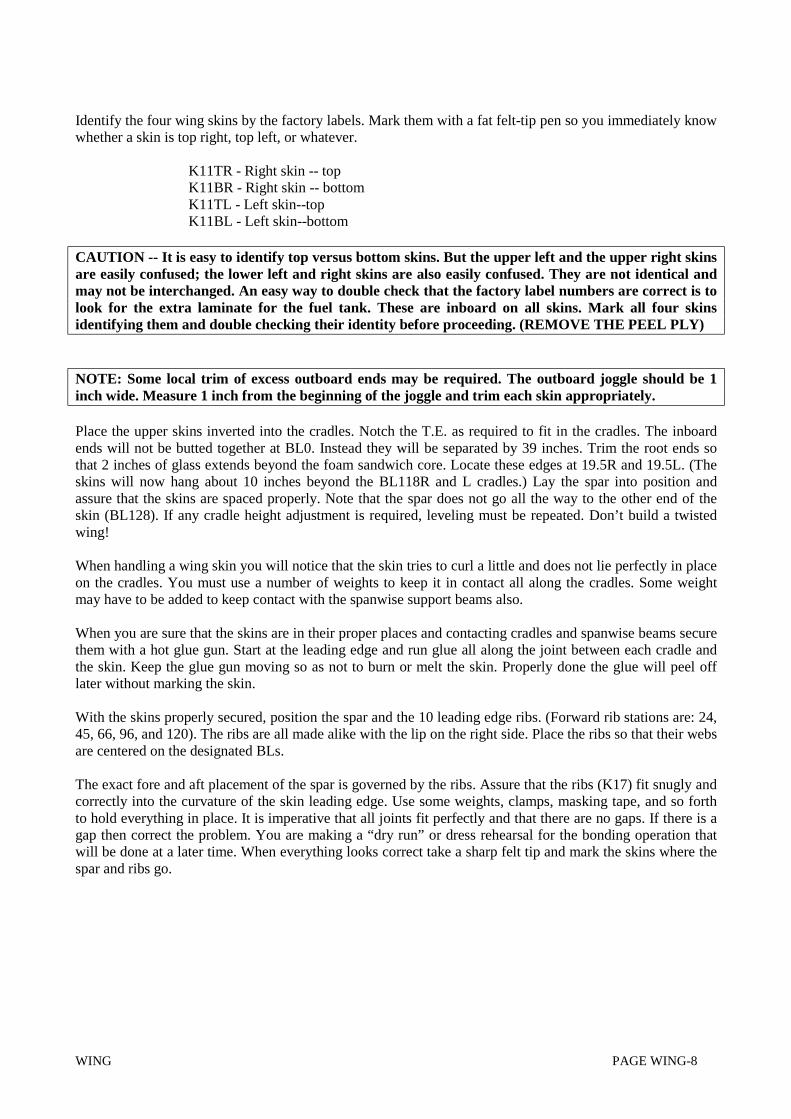
NOTE: Some local trim of excess outboard ends may be required. The outboard joggle should be 1inch wide. Measure 1 inch from the beginning of the joggle and trim each skin appropriately.
Place the upper skins inverted into the cradles. Notch the T.E. as required to fit in the cradles. The inboardends will not be butted together at BL0. Instead they will be separated by 39 inches. Trim the root ends sothat 2 inches of glass extends beyond the foam sandwich core. Locate these edges at 19.5R and 19.5L. (Theskins will now hang about 10 inches beyond the BL118R and L cradles.) Lay the spar into position andassure that the skins are spaced properly. Note that the spar does not go all the way to the other end of theskin (BL128). If any cradle height adjustment is required, leveling must be repeated. Don’t build a twistedwing!
When handling a wing skin you will notice that the skin tries to curl a little and does not lie perfectly in placeon the cradles. You must use a number of weights to keep it in contact all along the cradles. Some weightmay have to be added to keep contact with the spanwise support beams also.
When you are sure that the skins are in their proper places and contacting cradles and spanwise beams securethem with a hot glue gun. Start at the leading edge and run glue all along the joint between each cradle andthe skin. Keep the glue gun moving so as not to burn or melt the skin. Properly done the glue will peel offlater without marking the skin.
With the skins properly secured, position the spar and the 10 leading edge ribs. (Forward rib stations are: 24,45, 66, 96, and 120). The ribs are all made alike with the lip on the right side. Place the ribs so that their websare centered on the designated BLs.
The exact fore and aft placement of the spar is governed by the ribs. Assure that the ribs (K17) fit snugly andcorrectly into the curvature of the skin leading edge. Use some weights, clamps, masking tape, and so forthto hold everything in place. It is imperative that all joints fit perfectly and that there are no gaps. If there is agap then correct the problem. You are making a “dry run” or dress rehearsal for the bonding operation thatwill be done at a later time. When everything looks correct take a sharp felt tip and mark the skins where thespar and ribs go.
WING PAGE WING-9
Remove the spar and ribs but keep all the weight and clamps handy because they will be needed for theactual gluing operation. Sand all the contact areas of the skin, ribs and spar with 80 grit sandpaper inpreparation for bonding.
We arc not quite ready to bond the spar and the forward rib pieces in place. The top skin must be preparedfor installation of the fuel tank filler neck and some special rib work must be accomplished.
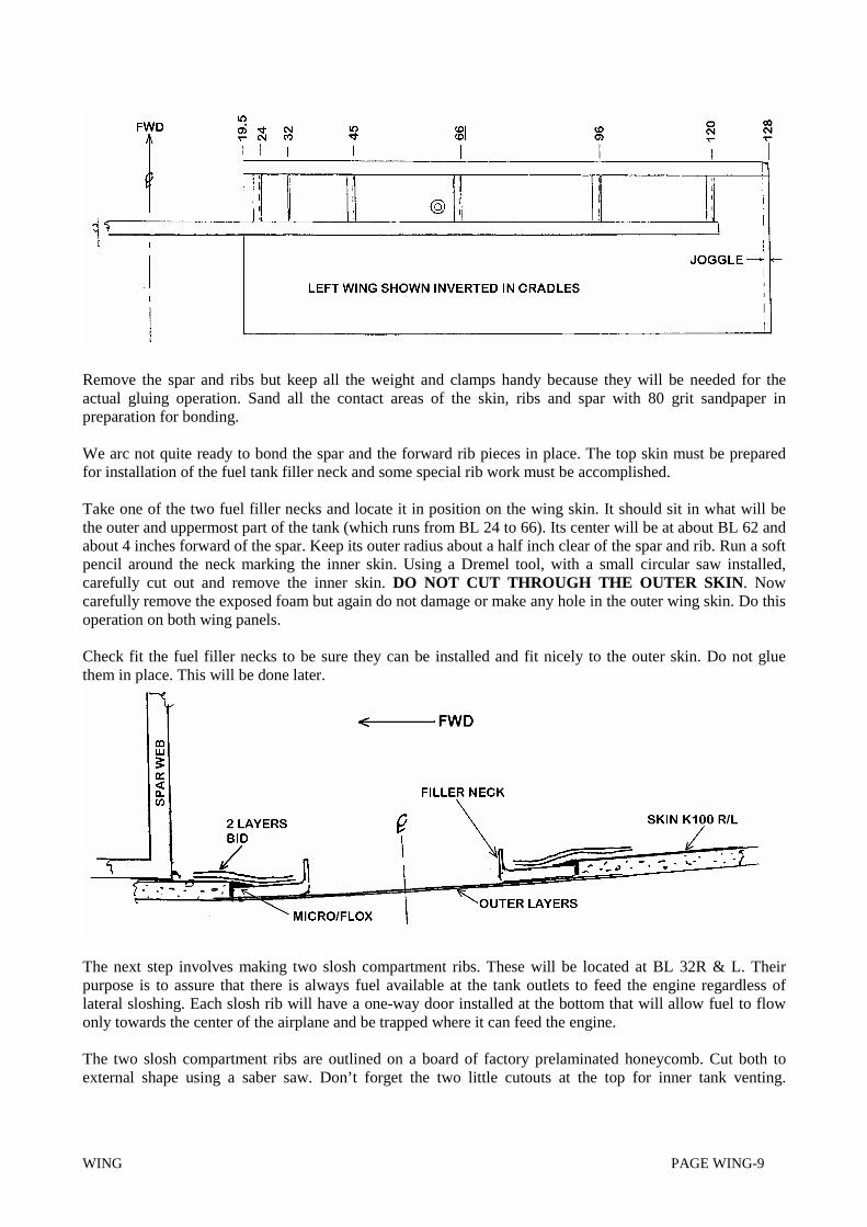
Take one of the two fuel filler necks and locate it in position on the wing skin. It should sit in what will bethe outer and uppermost part of the tank (which runs from BL 24 to 66). Its center will be at about BL 62 andabout 4 inches forward of the spar. Keep its outer radius about a half inch clear of the spar and rib. Run a softpencil around the neck marking the inner skin. Using a Dremel tool, with a small circular saw installed,carefully cut out and remove the inner skin. DO NOT CUT THROUGH THE OUTER SKIN. Nowcarefully remove the exposed foam but again do not damage or make any hole in the outer wing skin. Do thisoperation on both wing panels.
Check fit the fuel filler necks to be sure they can be installed and fit nicely to the outer skin. Do not gluethem in place. This will be done later.
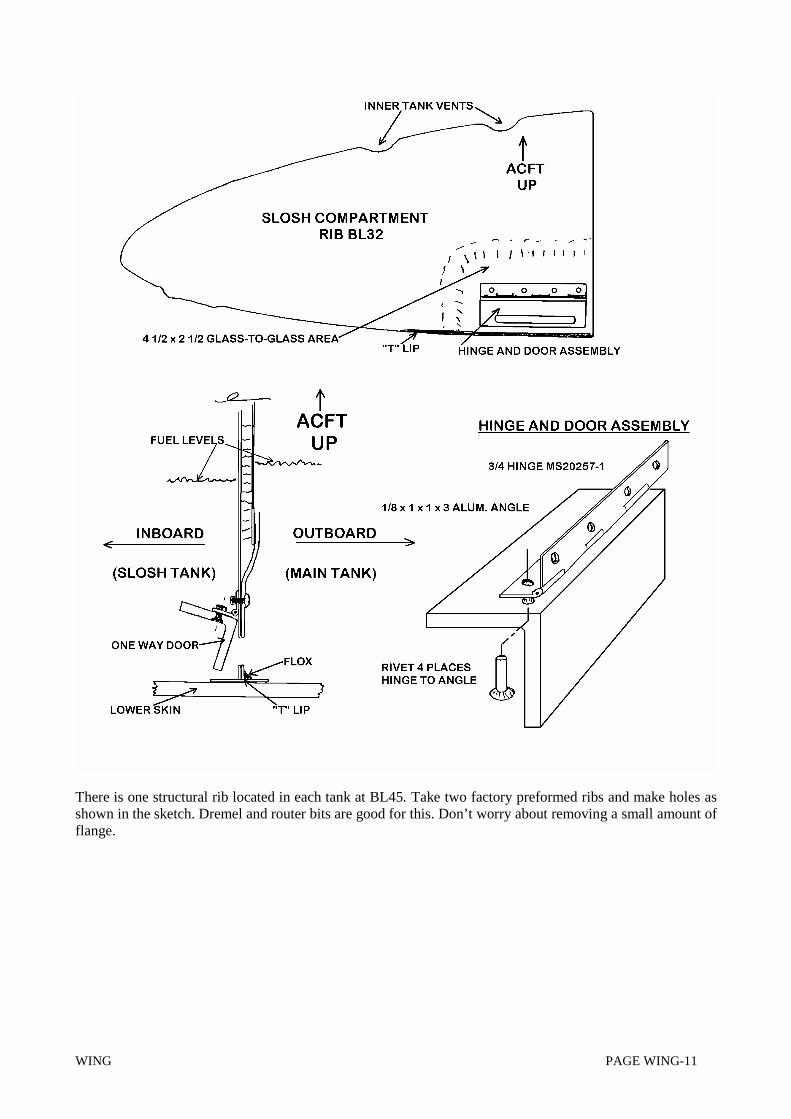
The next step involves making two slosh compartment ribs. These will be located at BL 32R & L. Theirpurpose is to assure that there is always fuel available at the tank outlets to feed the engine regardless oflateral sloshing. Each slosh rib will have a one-way door installed at the bottom that will allow fuel to flowonly towards the center of the airplane and be trapped where it can feed the engine.
The two slosh compartment ribs are outlined on a board of factory prelaminated honeycomb. Cut both toexternal shape using a saber saw. Don’t forget the two little cutouts at the top for inner tank venting.

WING PAGE WING-10
Temporarily fit them into place at BL32 R and L and be sure they fit okay. Relieve the Honeycomb about 1/8deep all the way around to form a channel for a micro/flox joint. Don’t micro/flox now.
Mark the 2½ x 4½-inch outline of the area around where the slosh door will be attached. Remove theoutboard skin and Honeycomb. Lay-up two layers of BID reinforcement on the outboard side of the rib inthis area as shown in the drawing. After cure, cut a 3/8 x 2 inch fuel passage hole in each rib; a Dremel toolwill work well.. This hole should be ¼ inch above the bottom edge and about 1-inch forward of the back(spar) edge of the rib.
It is time to make and install the one-way slosh doors. Cut two pieces of 1/8 x 1 x 1 aluminum angle threeinches long. Also cut two pieces of ¾ inch aluminum hinge (M520257-1) three inches long. Remove thepivot wire in the hinge and cut it about 1/8 short. Reassemble the hinge and trap the pivot wire inside bymashing the hinge closed on each end. Drill and rivet each length of hinge to one of the angle pieces usingfour 3/32 countersunk rivets (AN426-AD-3-8 cut to length).
Now position the doors on the ribs so that they cover the fuel passage holes but swing at least 1/8 inch clearof the bottom edge and ½ inch clear of the back or spar-end of the rib. Rivet each hinge/door assembly inplace with four rivets. Test door operation. Tilt the ribs to simulate flight gravity. Gravity alone should causethe doors to swing absolutely freely; correct any binding problem. Discreetly apply a very small amount ofoil or grease to each hinge to help reject any random drops of epoxy that might fall onto them during theconstruction phase. Check to be sure that each door closes properly thereby sealing the hole when side forcestry to let gas run from the slosh compartment.
Two protective “T” lips must be made, one for each slosh rib. These will be installed on the lower edge ofeach rib beneath the one-way door to prevent flox or epoxy from accidentally getting into the door or hingemechanism during the final process of installing the bottom wing skins. The rib lips are made by wetting-outtwo plies of BID on a flat surface covered with plastic or aluminum foil. Trim to make two flat pieces oneinch by six inches. After curing lift them and sand both sides. Carefully install them on the bottom edges ofthe ribs using flox fillets on the outboard sides as shown. Masking tape will hold them in place until cured.Put the slosh ribs aside until needed.
WING PAGE WING-11
There is one structural rib located in each tank at BL45. Take two factory preformed ribs and make holes asshown in the sketch. Dremel and router bits are good for this. Don’t worry about removing a small amount offlange.

WING PAGE WING-12
Take 2 prefabricated ribs and designate them for BL24 R & L. Prior to installing these two ribs each musthave an aluminum pad bonded into the lower back inside corner near the spar. (Location is important toassure fuel feed in a nose high attitude.) These pads are for the fuel finger filters. Start by cutting two blocks1½ x 2 from ¼ thick aluminum. Drill ½ as shown in the picture. This hole should end up as low on the rib aspossible without chancing aluminum break-out during later tapping with a 3/8-24 pipe tap. Place each blockinto the corner of its rib and mark its position. Remove the inside layer of glass that the rib was sitting on.Remove the foam core material so the aluminum pad can sit directly on the glass skin.
Use 80 grit paper to rough all surfaces of the aluminum blocks. Rough the inside of the ribs. Flox them intoposition and cut a piece of BD big enough to cover the aluminum and one or two inches of the surroundingarea. Resin the glass in place. Then cover the entire inside of both ribs including the glass over the aluminumblock areas with one additional layer of BID. Slit the glass where necessary to cause it to lay flat in thecorners and up onto the lips. Leave the lay-up a little resin rich (i.e. a little wet). After cure the aluminumpads will be very securely attached to the two ribs and both ribs will have an extra layer of BID on their innersides.
WING PAGE WING-13
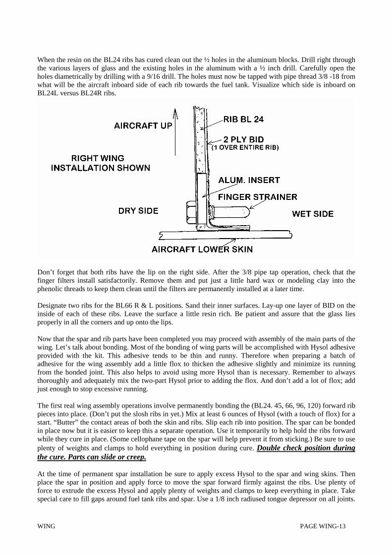
When the resin on the BL24 ribs has cured clean out the ½ holes in the aluminum blocks. Drill right throughthe various layers of glass and the existing holes in the aluminum with a ½ inch drill. Carefully open theholes diametrically by drilling with a 9/16 drill. The holes must now be tapped with pipe thread 3/8 -18 fromwhat will be the aircraft inboard side of each rib towards the fuel tank. Visualize which side is inboard onBL24L versus BL24R ribs.
Don’t forget that both ribs have the lip on the right side. After the 3/8 pipe tap operation, check that thefinger filters install satisfactorily. Remove them and put just a little hard wax or modeling clay into thephenolic threads to keep them clean until the filters are permanently installed at a later time.
Designate two ribs for the BL66 R & L positions. Sand their inner surfaces. Lay-up one layer of BID on theinside of each of these ribs. Leave the surface a little resin rich. Be patient and assure that the glass liesproperly in all the corners and up onto the lips.
Now that the spar and rib parts have been completed you may proceed with assembly of the main parts of thewing. Let’s talk about bonding. Most of the bonding of wing parts will be accomplished with Hysol adhesiveprovided with the kit. This adhesive tends to be thin and runny. Therefore when preparing a batch ofadhesive for the wing assembly add a little flox to thicken the adhesive slightly and minimize its runningfrom the bonded joint. This also helps to avoid using more Hysol than is necessary. Remember to alwaysthoroughly and adequately mix the two-part Hysol prior to adding the flox. And don’t add a lot of flox; addjust enough to stop excessive running.
The first real wing assembly operations involve permanently bonding the (BL24. 45, 66, 96, 120) forward ribpieces into place. (Don’t put the slosh ribs in yet.) Mix at least 6 ounces of Hysol (with a touch of flox) for astart. “Butter” the contact areas of both the skin and ribs. Slip each rib into position. The spar can be bondedin place now but it is easier to keep this a separate operation. Use it temporarily to help hold the ribs forwardwhile they cure in place. (Some cellophane tape on the spar will help prevent it from sticking.) Be sure to useplenty of weights and clamps to hold everything in position during cure. Double check position duringthe cure. Parts can slide or creep.
At the time of permanent spar installation be sure to apply excess Hysol to the spar and wing skins. Thenplace the spar in position and apply force to move the spar forward firmly against the ribs. Use plenty offorce to extrude the excess Hysol and apply plenty of weights and clamps to keep everything in place. Takespecial care to fill gaps around fuel tank ribs and spar. Use a 1/8 inch radiused tongue depressor on all joints.

WING PAGE WING-14
Take no chance that the parts slowly slide out of position during cure. Check everything halfwaythrough the cure cycle to assure that everything has stayed tightly in position.
When the Hysol has cured, the weights and clamps can be removed. Mix a cup of micro/flox. Apply filletsaround the ribs and along the spar in the gas tank area. Micro/flox both sides of ribs BL24 and 66 and thespar in this area. This application adds both strength and helps to seal the fuel into the tank.
The two gas filler necks can now be permanently installed in the upper skin. They go as far outboard and asnear the spar as possible. See the previous drawing. Rough up the inside skin around the area and rough themetal contacting surfaces with some sandpaper. Flox the necks into position. Cut three layers of BID andresin them over the necks. If necessary use a little micro/flox fill as required before adding the glass. Leaveno air holes or gaps. When the epoxy has cured carefully remove the outer glass layer. Try not to scratch thefiller neck when removing this glass.
The next step is to assure that the inside surfaces of the fuel tank have no pinholes and are fuel proof. Lightlysand the skin, rib and spar areas that are going to be wet with gasoline. Resin the entire area using asqueegee. Press firmly and squeegee the area almost dry. Also resin both sides of the slosh ribs. In about 4hours, after the epoxy has partially cured, go over the entire area again with the squeegee. Add more epoxyand squeegee again but leave a little wet this time. To save time treat the bottom skin fuel tank areas thesame way.
When the resin from the above steps has cured locate the slosh ribs at BL32R and BL32L. Mark theirposition on the skins and remove the ribs. Again sand the skins within about two inches of the rib locations.Fill the channels around the slosh ribs with micro/flox wherever they will contact the upper skin. Put the ribsin place. Go around the ribs with a little micro/flox to form fillets. Apply a 2-inch wide BID tape (cut on the45) over the fillets to tie the slosh ribs securely to the upper skin and spar. Keep the tape wet with epoxy. Besure to keep the slosh doors clean and working freely.
Next you will temporarily position the 10 center rib pieces K18 and the aft spar members K14R and K14L onthe upper skin.
CAUTION: Note that the aft spar members are not left and right reversible; their inboard ends have solidwebs rather than foam filled centers. Verify the factory labels and add your own magic marker “LEFT” and“RIGHT” markings. Also mark aircraft “UP” on these pieces. Note that the spar lips will face forward and fitaround the ends of the ribs.
Prior to temporary installation of the aft spar the inboard ends must be cut to shape. Hold the parts to a brightlight. Verify and mark the two reinforced areas. Establish exact BLs from the locations of the BL26 to 28reinforcements. Proceed and cut off the ends as shown.

WING PAGE WING-15
When installed the aft spars must be properly spaced out from aircraft center line. The pointed ends are to beat BL19R & 19L. This makes the ends 38 inches apart. The outboard end of each will extend a little beyondthe end of the skin.
The center rib pieces go at BL24, 45, 66, 96, and 120. Mark each rib piece to assign it to a BL. Also mark theribs with an arrow signifying aircraft “up”. The reason for this is that ribs must be modified before they arebonded into place. They will then be non-interchangeable.
Weight, clamp, tape or otherwise cause the pieces to be properly held as though you were going to gluethem. Run a magic marker around the parts and remove them. Sand (80 grit) all the contacting surfaces sothey are ready to glue.
Using hole saws and/or saber saw cut the aileron control tube clearance holes in BL 24, 45, 66 and 96 ribs.See separate drawings for details.

WING PAGE WING-16

WING PAGE WING-17

WING PAGE WING-18

WING PAGE WING-19
Modify the BL96 center ribs by adding the bellcrank reinforcement in each. To do this cut two 3 x 3 piecesof ¼ inch plywood. Remove a 3 x 3 inch inside layer of glass and foam on the inside of the rib web whereshown. Note that the plywood plate is canted downward about 3 degrees at the back. Flox the plywood intoposition and cover with 2 layers of BID. Be sure that the BID extends about an inch onto the rib web forstrength. Note that the reinforcement goes on the inboard side of these ribs even though the bellcranks willultimately mount on opposite sides.
Assemble the aileron bellcranks and brackets as shown in the drawing. First place the bearing on thebellcranks, drill four rivet holes and rivet a bearing to each bellcrank. The side of the bearing that thebellcrank is seated on will be top. Now assemble the brackets, bellcrank, bolts, washers, nuts, and cotter pins.
Place the bellcrank assemblies onto the BL 96 ribs after the epoxy and glass are cured. Jig drill four 3/16bracket attach holes through the brackets and plywood plates and mount each bellcrank assembly to its ribwith four AN3-6A bolts and stop nuts. Rib BL96 mods are complete.
Now that all rib modifications are complete the center ribs may be bonded into place on the skins togetherwith the aft spars using Hysol adhesive. Once again make sure that all the parts are properly positioned andwell secured during the cure period. Check that the aft spar ends are at BL19 R & L. There should be 38inches between them.
A STRAIGHT BOARD MAY BE REQUIRED TO HOLD THE T.E. STRAIGHT
It is now time to add the gas tank vent tubes, gas gage tubes, and the pitot/static lines. All of these will be ¼inch soft aluminum tubing which should be roughed with sandpaper at the proper places for good epoxyadhesion.
Note: This text describes an inexpensive boiler sight tube type fuel gage system. If the builderdesires a superior measuring system he should incorporate a capacative system such asmanufactured by Westach or Sky Sports. The fuel gage feed tubes and gage vent tubes shown inthis section can then be eliminated. Follow the manufacturer’s instructions when installing thesenders to sense slosh tank levels.

WING PAGE WING-20
Install a gas tank vent tube in each tank. These tubes will go from the outboard upper corner of each tank atBL66, through a ¼ inch hole in BL96 rib, and then out to a little beyond the wing skin end. After wingclosure they will be bent to exit the bottom skin. For the time being allow each to extend about 4 inchesstraight out of the wing. Bond both vent tubes to the upper skin and ribs at a number of places with micro/flox. To avoid leaks, be sure to adequately seal where the gage vent tube goes through gas tank ribs. Sand thetube surfaces for adhesion. Apply micro/flox to both sides of the ribs around the tube is good for this. Alsoput a little BID over the micro/flox to help hold it in position rather than creeping during cure.
Two fuel gage tubes are required for each tank; one will come out of the bottom of the tank and one out ofthe top. Start by adding the gage vent tube from the top of the tank. It will run from the inboard side of BL66rib (in the proximity of the gas tank vent tube), through the tank, through BL32 rib, and out beyond BL24rib. Leave about 4 inches extend out of the tank for hook up into the fuselage later. Bond it to the upper ribsand top skin with micro/flox. Again seal adequately at the ribs BL24 and 66 to minimize leaks.

WING PAGE WING-21
WING PAGE WING-22
Now install the bottom fuel gage feed tube. It should run from the bottom of the tank just outboard of BL32rib and then exit through BL 24 rib. As with the other gage lines leave about 4 inches of tube outside theBL24 rib for later hook-up to fuselage gage lines.
Two additional tubes must be installed for pitot and static lines. These go in the left wing only. They runfrom inboard of BL24 rib, outboard through the center bays and terminate near the bellcrank. (After thelower wing skin is added these tubes will be connected by flexible hose to the pitot/static probe assemblywhich will be part of the removable aileron bellcrank inspection door.) Keep the aluminum tubes clear of thepushrod tube and the bellcrank. Securely flox them to the ribs that they go through and to the upper skin.
Many builders will desire night position and/or strobe lights. (Whelen multipurpose A600-PG/PR units dowell.) If lights are being installed or perhaps added later this is the time to install a wiring tube (½ PVC) orotherwise run wiring through the center bays of the wing. Be sure to keep any tube or wiring to aeronauticalstandards, clear of all controls and well secured.
While the wing is open it would be wise to check and assure that the long push tubes for aileron control haveadequate clearance through the holes in the ribs. The tubes run from the bellcranks inboard through the ribholes to the fuselage. They will be made from 1 inch diameter 2024T3 aluminum tube about seven feet long.They will be fitted with ball rod end terminals at both ends for interface to the aileron bellcranks and fuselagecontrol sticks. To check the hole clearances in each wing bolt a rod end fitting to the upper side (aircraft topside) of the long arm of the bellcrank; place the tube through the ribs and align it with the rod end fitting. Thecenter of the tube should be 1/2 inch above the top of the bellcrank at the outboard end and centered in theBL 24 rib. Modify holes if necessary and remove the tubes.
The aft spar must have a hole for the short push tube to go straight back from the bellcrank to the aileroncontrol bracket. The tube will be ½ inch diameter and again be fitted with ball rod ends. Cut a 1-inch hole inthe spar web using a Dremel tool and router bit. Center the hole as low as possible on the spar. It should be atstation 92.8. Check that this is where your push tube will be located before cutting the hole. This hole can beopened more later when the aileron is mounted and push rod is in place.
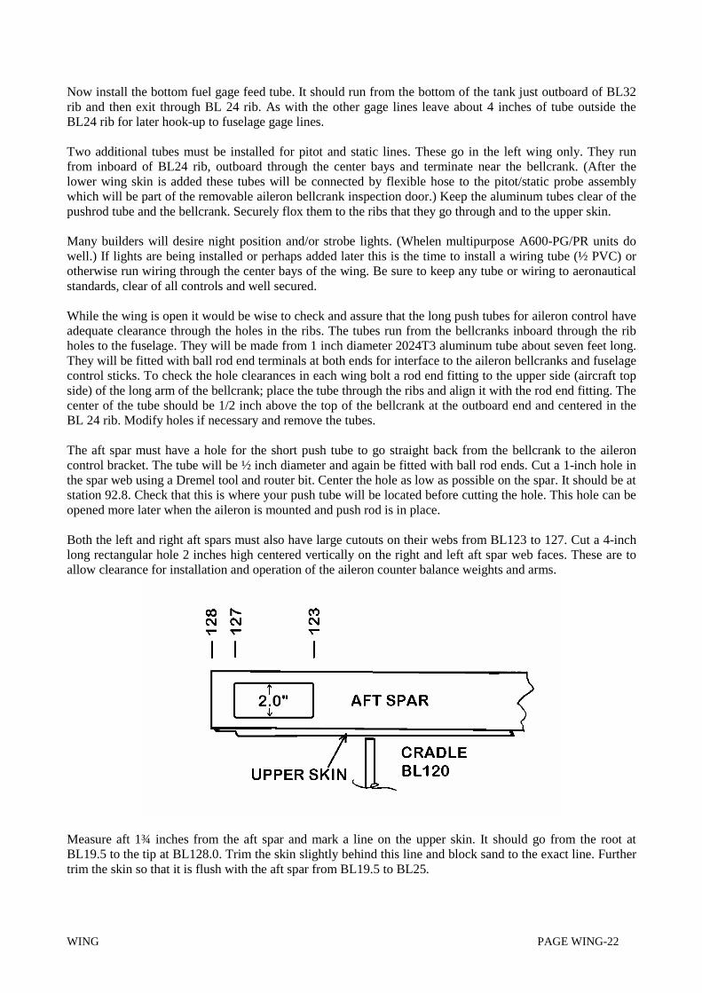
Both the left and right aft spars must also have large cutouts on their webs from BL123 to 127. Cut a 4-inchlong rectangular hole 2 inches high centered vertically on the right and left aft spar web faces. These are toallow clearance for installation and operation of the aileron counter balance weights and arms.
Measure aft 1¾ inches from the aft spar and mark a line on the upper skin. It should go from the root atBL19.5 to the tip at BL128.0. Trim the skin slightly behind this line and block sand to the exact line. Furthertrim the skin so that it is flush with the aft spar from BL19.5 to BL25.

WING PAGE WING-23
Mount the inboard flap hinges KS-9 R & L to the rear faces of the right and left aft spar as shown in thedrawings. (Flanges face outboard.) These hinges are different from the other strip hinges because they mustcarry higher loads incurred at that BL. The center of the hinge bushing hole must be exactly in line with theskin trailing edge. This aligns it with the strip type hinges which pivot on the same line. Drill the mountingbolt holes so as to not only keep the hinge pins in alignment but also to locate the center of the bearing at BL26.5.
Now 45-degree bias cut about 20 feet of BID about 5 inches wide. This will be used for aileron hinge mountreinforcement at the trailing edge. Cut it into 20 strips 11 inches long. Prelaminate these strips into four 5-plyPreLams trimmed to 4 wide by 10 inches long. Measure in from the tip as shown on the drawing and applythe PreLams so that the glass extends up the spar at least one inch. Relieve the T.E. about 3/32 by 8 incheswhere the hinges go.

WING PAGE WING-24
It is time to prepare for installation of the lower skins that will close the wing. Before installing the skinsmake sure that they have been trimmed at the outboard end so that the joggle is 1 inch wide. When properlylocated the outboard end of the lower skin will be flush with the outboard end of the upper skin.
Carefully examine the way the skins fit. If there are problems correct them. If any contacting surfaces are toohigh sand them down.
Using a felt tip pen, lift the skins enough to mark the approximate rib and spar locations on the skins.Remove the skins and complete the marking. Use 80 grit paper to completely rough all those areas plus theentire surface of that area of the skin that fuel contacts. Also rough the joggle areas that will come together.
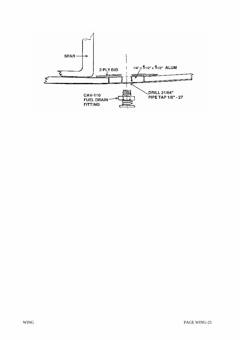
A fuel drain must be installed at the low point in each fuel tank prior to installing the lower wing surface. Cuttwo pieces of ¼ aluminum 1½ inch square. Locate these as close to rib BL24 as possible. Their centersshould be about 11 inches behind the leading edge. Outline each piece and cut out the inner glass skinlaminates. Install the aluminum pieces with micro/flox. Cover each with 2 plies of BID that extend an inchonto the skin. Do not extend the glass such that it falls under the spar or that member will not have a perfectflat surface to sit on and be bonded to. After cure carefully drill the aluminum 2 1/64; start with a small drilland work up in size. Carefully pipe tap the aluminum 1/8 - 27 from the outer side of the skin. Take thisoperation slowly. Check the drain fittings for fit. Remove the fittings and fill the hole and threads withmodeling clay.
WING PAGE WING-25

WING PAGE WING-26
Aileron inspection doors must also be incorporated in the wing lower skin prior to bonding the skin in place.They will be 6 inches square located just inboard of BL96 rib and below the bellcrank. Mark the outline onthe skin and cut the door with a saber saw. Apply plastic tape over the entire inner surface of the door. Placethe door back in position and tape it on the outer side of the skin to hold it firmly in position. Epoxy 3 layersof BID over the door and surrounding skin on the inner side to form a shelf. After cure again remove the

WING PAGE WING-27
door and cut out the center of the glass shelf leaving a lip about ½ inch wide with generous corners for theattach screws.
Remove about 1/8 inch of foam around the edges of both the door and the opening in the skin for a smoothmicro edge. Remove about ¾ inch at the corners of the door for micro fill where the retention screws go. Fillthese channels with dry micro. Sand the doors smooth after cure. Drill and countersink the corners and securethe door with four #8 countersunk screws (MS24694-S9). The screws go into K1000-8 anchor nuts riveted tothe inner side of the glass shelf.
Repeat the same steps for the aft spar access doors located from BL19 to 23 and just forward of the aft spar.This door is about 4 x 6inches and provides access to the aft spar attach bolts.
You may want to install radio antennae in the lower wing skins. This is the time to do it. (All antennae in theprototype were located in the fuselage.)
You are now ready to proceed with bonding the bottom wing skin to the structure. First squeegee epoxy resininto the skin where the fuel will be if this has not been. Be sure to cover the entire area that will be wet. Useconsiderable pressure to force the resin into the voids. Let it cure for four hours and squeegee again withresin but this time leave it slightly wet. Complete closure of the wing while the epoxy is still wet or repeatsurface roughening prior to closure.
CHECK THAT THE JIGS ARE STILL LEVEL. WING STRAIGHT.
Now get another person to help with the actual closure bonding. Practice placing the wing skins into positionwith only vertical motion. This is to assure that horizontal motion does not upset the bonding materials. Sandall contact surfaces with 80 grit paper. Mix some flox and fill the groove in the slosh rib. Pile some excess ontop of the rib. Now mix a big cup of Hysol epoxy adhesive; (flox can also be used but don’t use incombination with Hysol) apply it in excess to the contacting surfaces (ribs, spars, and the leading edge jogglearea of both skins). Put some on the various 1/4 inch aluminum tubes. Be generous around fuel tank flangearea. (Beware that no Hysol gets anywhere that it can jam the anti-slosh doors.) Remember that you aresealing the tank at this time. IT’S YOUR ONLY CHANCE!
With the help of the second person place the lower wing skin in place. Go over the entire skin and applyhand pressure to assure that it is properly seated into the micro/flox adhesive. When you are satisfied placeweights all over to hold bonding pressure. The skin should be weighted along each rib and both spars. Alignjoggle and drill every 3 inches and pop rivet together with soft alum rivets. In the fuel tank area use sheetmetal screws. Don’t strip the holes.
When the adhesive has cured carefully drill off rivet heads with out popping shank through. This works byusing a larger bit and going slow. The resin from the tapes that you are about to add will hold the shanks inplace. Go over the leading edge joggle area with sandpaper. Prepare some long 2-ply PreLarns (45 degreeBID) 2¼ inches wide for along the wide inset area at the spanwise joggle near the leading edge. Squeegee thePreLams in place. Where splicing is necessary overlap by 2 inches.
Prepare four 5 layer BID PreLarns to reinforce the trailing edge at the flap hinge locations. Apply thesewhere shown on the drawings after roughing the areas with sandpaper.

WING PAGE WING-28
Relieve the upper skin trailing edge by 3/32 inch where the aileron hinges are installed just as you did whenyou built the stabilizer and elevator. In a similar manner relieve the lower skin for the flap outboard andcenter hinges. Install eight hinges, four aileron and four flap, with #8 c.s. screws, Tinnerman washers, andelastic stop nuts.
Drill two ¼ inch holes in the bottom skins near BL120 for the tank vents. Reach inside the wing and bend thetank vents to pass through these holes. Cut the vents off 1½ inches outside the bottom skin. File the ends offat an angle or bend them forward to cause a slight ram air pressure in the tanks.
Take some ¼ inch soft aluminum tube and make a pitot/static assembly as shown in the drawing. Attach thispermanently to the left aileron bellcrank access door. Make a fairing of flox inside and outside to securelyretain the tubes. Do not install this door at this time. This will protect the pitot/static tubes during aircraftfinishing and assembly.

WING PAGE WING-29

WING PAGE WING-30
BUILDING THE WING - LARGE FUEL TANKS
The large fuel tanks provide approximately 34 vice 20 gallons of capacity. They are recommended forutilization only with engines such as the Lycoming 0-235 and others requiring more than the 20 gallons.
Notice: Thirty four gallon tanks are not recommended for KIS airframes with small engines. The addedfuel weight will significantly limit the useful occupant and baggage payload of such aircraft. (Seerecommended gross weight limits in “Weight and Balance” section.) Persons desiring fuel tanks of morethan 20 and less than 34 gallons should call the factory for technical support.
Study the preceding section entitled “Building the Wing - Standard Tanks” so that you understand themethod of building the integral wing tanks. Now thoroughly read below to understand the main differenceswhen building a wing with large tanks. As you build you will primarily refer to the preceding section so takesome time and go back and mark-up where the differences are to avoid mistakes later.
You will notice that the span-wise length of the standard versus large tanks differ. The standard tanks gofrom BL24 to BL66. The large tanks extend for one more rib bay; they go from BL24 to BL96.
Other major differences are as follows:
1) LOCATION OF THE FILLER NECKS: These should be located about BL92 versus BL62. (Seepg. 10.)
2) RIB K-17 BL66R & L: These ribs are no longer the outboard ends of the tanks. Modify themlike the BL45 ribs. (Upper drawing pg.12.)
3) RIB K-17 BL96R & L: These ribs become the tank ends. Laminate them with extra layers ofBID as described in the second paragraph pg.14.
4) VENTS: As described on pg.21 and shown on the drawing on pg.22, the gage vent and tank ventterminate inboard of ribs 66R & L when building the standard tanks. When configuring the largetanks terminate these vents one bay out, i.e. just inboard of ribs 96R & L.
5) FUEL PROOFING: Be sure to micro-flox around BL96 ribs (vice 66) as called out in paragraph5 page 14. Apply all other special resin coatings on internal skin, ribs and spar out to BL96, etc.