Hawker Hurricane Mk II Construction Manual Construction Manual.pdf · Hawker Hurricane Mk II...
111
1 Hawker Hurricane Mk II Construction Manual Scale: ¼ exactly Span: 122 inches Wing area: 2477 square inches Fuselage length: 8 feet. Weight: 48 lbs (electric version) 51 lbs (gas version) Designed by David P Andersen 2014. Free plans on www.mnbigbirds.com Prototypes by Roy Maynard, Jeff Quesenberry, Chris O’Connor, Barry Vogel, Chuck Hamilton and Richard Rice (New Zealand). They also contributed ideas into the design. Thanks, guys. Table of Contents: Parts List Page 2 Fin Construction Page 51 Fuselage Page 6 Rudder Construction Page 55 Fuselage--Gas Motor Page 27 One-piece Stab Page 60 Radiator Page 29 Removable Stab Page 65 Oil Cooler Intake Page 36 Wing Center Section Page 72 Oil Cooler Installation Page 40 Outer Wing Panel Page 82 Retract Specifications Page 41 Surface Details Page 93 Flap Assembly Page 42 References Page 95 Elevator Assembly Page 46 Walk Around Photos Page 99
Transcript of Hawker Hurricane Mk II Construction Manual Construction Manual.pdf · Hawker Hurricane Mk II...

1
Hawker Hurricane Mk II Construction Manual
Scale: ¼ exactly
Span: 122 inches
Wing area: 2477 square inches
Fuselage length: 8 feet.
Weight: 48 lbs (electric version) 51 lbs (gas version)
Designed by David P Andersen 2014.
Free plans on www.mnbigbirds.com
Prototypes by Roy Maynard, Jeff Quesenberry, Chris O’Connor, Barry Vogel,
Chuck Hamilton and Richard Rice (New Zealand). They also contributed ideas
into the design. Thanks, guys.
Table of Contents:
Parts List Page 2 Fin Construction Page 51
Fuselage Page 6 Rudder Construction Page 55
Fuselage--Gas Motor Page 27 One-piece Stab Page 60
Radiator Page 29 Removable Stab Page 65
Oil Cooler Intake Page 36 Wing Center Section Page 72
Oil Cooler Installation Page 40 Outer Wing Panel Page 82
Retract Specifications Page 41 Surface Details Page 93
Flap Assembly Page 42 References Page 95
Elevator Assembly Page 46 Walk Around Photos Page 99

2
Parts List
Balsa sheets:
14—1/16 x 3 x 36 Fin & stab base, stab sheeting, fin sheeting
42 – 3/32 x 3 x 36 Fuselage sheeting, 4-6 lb contest grade.
3—3/32 x 4 x 24 Flap cores
5—1/8 x 3 x 36 Fin & stab ribs, rudder base, trim tabs
20—1/8 x 3 x 48 Outer wing panel sheeting
38—1/8 x 4 x 36 Sheer webs, inner panel sheeting, outer wing ribs
2—1/4 x 3 x 36 Stab support, stab reinforcement
1—3/8 x 3 x 36 Fin LE, elev trim tabs, stab & elev tips
2--1/2 x 4 x 36 Radiator bottom & sides, F23, fin fairing
2—1 x 3 x 12 Rudder top, elev horn support
1—3/4 x 3 x 36 Inner panel LE
2—3/4 x 3 x 48 Outer panel LE, gear door fairings
Balsa Blocks:
3—2 x 4 x 12 Wing tips, radiator front (if balsa radiator is elected)
1—2 x 4 x 2 Oil cooler intake (if carved balsa scoop is elected)
Balsa sticks:
7—1/8 x ¼ x 36 Elevator cross braces, aileron spars, elev spar
62—1/4 sq x 36 Fuse stringers, elevator balance
7—1/4 x ½ x 36 Stab spar, flap hinge support
2—1/4 x 1 x 36 Stab TE
5—½ sq x 36 Spars
5—½ x ¾ x 48 Spars
4—½ x ¾ x 36 Elev LE, aileron hinge supports
2—3/8 x ½ x 36 Stab LE
1—½ x ½ Triangular Rib gussets.
Hardwood sticks:
1—1/4 x ½ x 6 Doubler
1—3/4 sq x 36 Lower center section main spar
1—1/2 x ¾ x 36 Lower center section rear spar
1—1/4 birch dowel Stab alignment, wing LE support, wing alignment
Poplar Light Plywood:
6—1/8 x 12 x 48 Formers, stab ribs, wing ribs, servo support, washout sticks
Birch Plywood:
2—1/64 x 12 x 24 Flaps, wing filet
1—1/32 x 12 x 24 Lower wing filet

3
1—1/16 x 8 x 12 Radiator base, antenna base
1—1/8 x 12 x 24 Battery box floor, stab ribs, F3, servo tray
1—3/16 x 8 x 8 F3 electric motor firewall
1—1/8 x 12 x 48 Ribs 8 & 9 (2 each)
1—3/8 x 6 x 12 Wing bolt support, upper door supports
Estimated total wood cost: $445 list as of May 2014 from Balsa USA
Cut wooden parts are available from
Leon Cole, Belair Kits, www.belairkits.com Tel: +44 (0)1362 668658 (England)
Other hardware:
1--Hidden Latch System. http://www.details4scale.com.
Gun sight, seat, control stick, harness, instrument panel, pilot, etc.:
http://www.iflytailies.com
1 pair—Central Hobbies ¼” x 38” Carbon Rods/Titanium Ends CHMPRS38T4,
http://www.centralhobbies.com/control_linkage/pushrod2.htm
2—7/8” x 30” aluminum wing tubes with sleeves (Ziroli Plans)
1-- 5/8” x 18” aluminum tube w/phenolic socket (TnT Landing Gear). Removable stab only.
23—Robart Super Hinge Points and Pockets
2 – K&S 9/32 x .014 Stock #107 aluminum tube (Robart hinge extensions)
1—5/32 x 36 music wire Elevator horn
1--1/16 x 3 x 6 Aluminum Rudder horn
2—SIG SA1025/32”Nose wheel steering arm--Elevator horns
9—4-40 threaded music wire (elevator and flap pushrods)
2—4-40 Ball links (aileron servos)
10—4-40 Kwik Link clevices (flaps, tailwheel)
Molded parts available from Micko Aircraft and Accessories (www.mnbigbirds.com):
Canopy
Cowl chin
Fiberglass radiator
Fiberglass oil cooler intake
Exhaust manifold (vacuum formed)
Alternatively, Nick Ziroli ZIR:SPIT7 Scale Exhaust
Manifold (cast resin)
ScaleRcParts (Kirk Schneider) 3D printed oil cooler (1 ¼ oz)
Contact: ScaleRcParts.com

4
3D printed cannon barrels and shrouds are available from ScaleRcParts.com.
3D printed Merlin hollow exhaust manifolds and cowl blisters available from ScaleRcParts.com.
Landing lights not shown.
6—1/4 x 20 DU-BRO nylon bolts Wings bolts, radiator
8 pkgs (80 feet) —1/16” x 120” Line O Tape pinstripe tapes masking tape (simulated stringers)
Landing Gear:
1 set Shindin Andersen Hurricane electric or air retracts
and struts (http://www.shindinmachine.com)
OR…
1 set John Mesolella Andersen Hawker Hurricane
electric (power box required) or air quarter-scale
retracts and tailwheel strut
Mattrix Machine Tool
100 Boxart St.
Rochester NY 14612
Alternatively, ROBART Giant Scale Fixed Tail Wheel Assy No. 657 (non-scale)
Alternatively, Mick Reeves quarter-scale Hawker Hurricane retracts
http://www.mickreevesmodels.co.uk/~mickreev/spits/p4spit.htm
For other retracts, see Quarter scale Hurricane retracts specs.doc
1 pair Mick Reeves 6” Hurricane wheels
http://www.mickreevesmodels.co.uk/~mickreev/spits/p4spit.htm
Alternatively, 1 pair ROBART 6” tires and A4 Large 4 spoke Spitfires hubs
http://www.robart.com/store/wheels/aluminum-wheels-4-6
1--DU-BRO 2 ½”smooth surface or ROBART 2 ¼” treaded tailwheel
1 pkg Tom Cook 1/16” air line tubing clamps
(http://www.jetmodelproducts.com/landing.htm)
1 pkg ROBART or Tom Cook 1/16” air line tubing
1--.025” x 8 x 18 aluminum sheet. Gear doors
2—10-24 stop nuts Axle ends
2—8-32 x ½” SH machine screws End strut set screws

5
2—1/4” DU-BRO wheel collars Axle spacing
4--#6 ½” wood screws Door guide
2—3/4” diameter strut collars (Sierra Giant Scale, http://www.sierragiant.com )
4—6-32 x ½” FH machine screws Sierra strut collars.
1—Cockpit kit, Dynamic Balsa (Brian), dbalsa.com
Sound System:
Model Sounds with two 4-inch speakers
http://www.modelsoundsinc.com
Model Sounds
Suite 712, 31 McEwen Avenue
Ottawa, Ontario, Canada, K2B 5K6
Alternatively,
http://www.aerosoundrc.com/ or
http://www.benedini.de/Home_E/Products_E/products_e.html
Power:
Hacker 150 or 200 electric motor or Turnigy RotoMax 100 electric from Hobby King
Power supply for electric motor: #9107000345-0/63509
Turnigy 9 Channel Independent Power Supply
Eight Thunder Power 7C 5000 mAh Lipo batteries
JETI SPIN 300 Pro Opto electronic speed control with one
EverCool EC 5015 5 volt DC, 4500 rpm, ball-bearing cooling fan
Or…
Desert Aircraft DA 100 twin cylinder inline gas engine
Or..
3W-Modellmotoren 3W 110iR2 twin cylinder inline gas engine
Or…
Kolm 100 or 150 or Valach VM 120i-4T twin cylinder inline 4-stroke gas engine
Vogelsang Aeroscale, www.team-aeroscale.com
DU-BRO 32 ounce gasoline fuel tank
Servos: 6—200 oz-in for flaps (4) and ailerons (2)
Markings:
Prop badges, step, stencils and other marking
decals in smaller scales are available from Mick
Reeves. ¼ scale versions forthcoming. See
http://www.mickreevesmodels.co.uk or email
“Hurricane Rivet Plates” vinyl graphics--email
[email protected] $8.00
Covering:
Rib tape: Quarter Scale Warbird Kit pinking tape, http://www.pink-it.net
1 yard Sig Koverall Rudder, elevator, ailerons
4 yards ¾ oz glass cloth plus resin
8 yards 1.4 oz glass cloth (wing), http://www.expresscomposites.com/
1/32” strip tape Simulated fuselage stringers
6
Fuselage Assembly
This section shows the fuselage construction for an electric motor. Most of the
fuselage construction is the same for a gas motor so it is not covered elsewhere.
The exceptions are described in “Fuselage Assembly--Gas Motor.”
The wing center section must be framed and its upper surface sheeted before
fuselage construction can begin. Fuselage assembly uses the inverted horizontal
crutch method. That is, a mid-fuselage frame (crutch) of ¼” square balsa is laid
down over the plans on a flat surface of wood or sheet rock to which parts can be
pinned. The bottom half of the fuselage is assembled inverted on this crutch.
After sheeting most of the bottom half, the wing center section is aligned and
permanently attached. The fuselage is then set upright, resting on the wing. The
upper formers and sheeting are added after the tail is attached.
The Hurricane fuselage has lots of low-stress surface area aft of the CG and
a very short nose. Therefore, all sheeting aft of the cockpit must be lightweight 4-6
lb contest grade balsa covered with lightweight glass cloth and a thin layer of resin
and paint or else the airplane could be hopelessly tail heavy.
Cut all formers and fuselage parts. This requires about 8 hours of work with a
scroll saw, disk sander and drill press. Fit the Hacker 150 motor to the 3/16” ply
former F3 using four ½” ply (or eight ¼” ply) spacers plus four M6 x 1-1/8” cap
screws and washers. Omit the spacers if a Hacker 200 motor is used. Remove the
motor during fuselage assembly.

7
Add ¼” square battery alignment guides to formers F4 thru F6.
Verify that the chin parts fit before assembling them over the crutch.
Note how F3 must dangle over the edge of the work bench.
Pin the crutch to a flat surface over plans covered with waxed paper. Glue formers
F4 thru F7 to the crutch. Verify that each is vertical or else the batteries may not
fit.
Install formers F8 thru F14. Add the wing saddle from F7 thru F12. The tabs on
F11 will insert into the wing to attach to the rear spar.

8
Plane the wing saddle to blend into F7.
With crutch hanging over the edge, glue the firewall F3 in place. Before glue sets,
trust but verify that the LiPo batteries will fit.
Add some stringers to the nose area to support the nose formers. Leave the bottom
open for now.
9
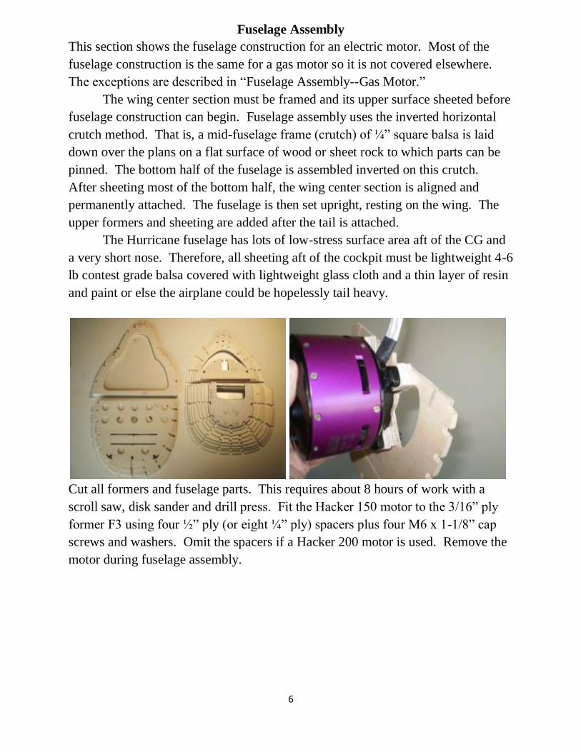
Fit the alternate position elevator (instead of in the tail) and rudder/tailwheel servo
tray between F12 and F13. The receiver, its battery and the audio card may also be
installed here. The servo tray will be accessible thru the bottom of the wing when
the radiator is removed.
Select either Robart #657 tailwheel assembly or Messolella tailwheel strut.
Robart is 1 ½ oz lighter. The Messolella strut, shown here, is more scale, more
shock-absorbing and more expensive.
Mark the positions of the rearmost formers, F22 and F23, on the crutch. Slide the
crutch off the end of the building board and glue F22 and F23. Use a square to
make them vertical. Attach the tailwheel to former F21 and glue it in place, tilting
it backwards 10°. Install the lowermost stringer at the same time to hold F21 at the
required angle.

10
The rear lower formers are now in place, ready for the remaining stringers to be
installed.
Install a carbon-fiber tailwheel pushrod while access is open.
Complete the installation of the stringers of the lower half of the fuselage.
Sheet the fuselage with 4-6 lb Very Light 3/32” x ” 4 x 36” balsa sheet.
IMPORTANT: Use only contest grade 4-6 lb balsa sheeting aft of the CG or else
the plane will be tail-heavy. The wing saddle area is now ready to receive the
wing center section.

11
Lay the wing center section on the wing saddle (shown here without upper surface
sheeting for clarity). Rib 3 and Rib 3a contact fuselage former F12. Rib 3 also
contacts formers F11 and F12 and the rear spar. Adjust and align if necessary.
Cut slots in the upper wing surface for the tabs in F11 and F12. Glue the wing to
the wing saddle and former 7, clamping the leading edge of the wing to F7. Tabs
in F11 and F12 project into the wing slightly ahead of the spars. Glue balsa blocks
to these, attaching them to ribs 3, 3a and the spars.

12
For extra strength, use a long 3/16 drill bit to drill thru these tabs, into the
hardwood spar. Then epoxy a 3/16 dowel to pin the tab to the spar. (Jeff
Quesenberry’s idea. Thanks, Jeff.)
Using a ¼” x 12” drill, drill three holes in the leading edge of the wing.
Glue three ¼” dowels into the wing and F7. Wet each hole and dowel with glue,
shove the dowel in place and cut it off with a razor saw.
13
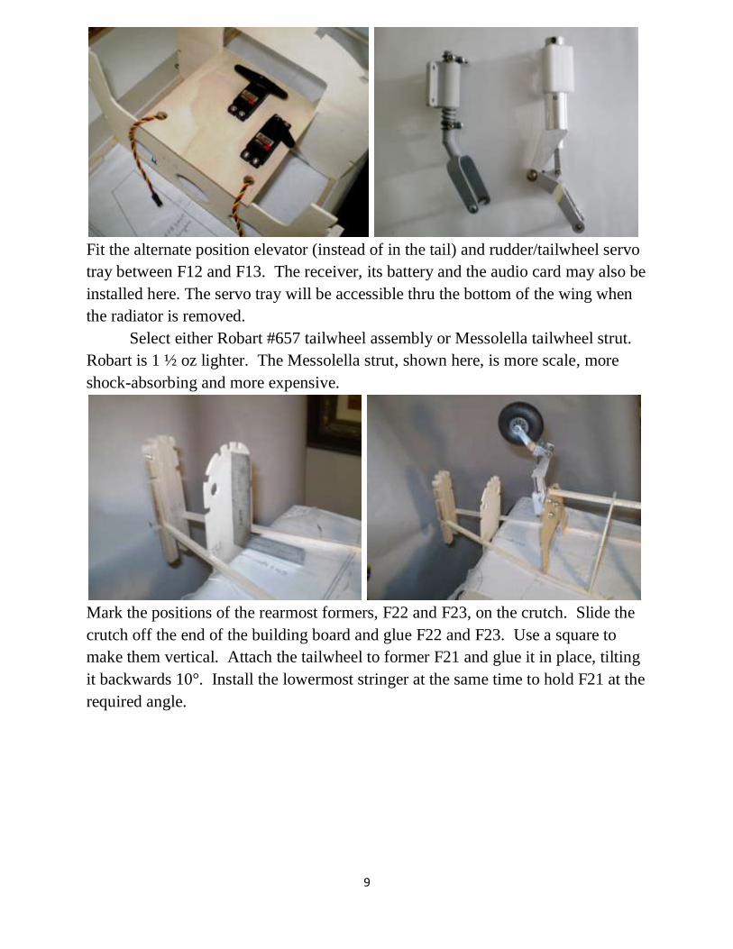
Cut the remaining ¼” sq. stringers for the nose, slightly oversized. Soak in hot
water and pre-bend. The bolts in the landing gear holes are a convenient bending
tool. Glue the center keel and stringers in place. Secure with pins and clamps until
the glue dries, then trim to length. Plane them to the formers if necessary.
Install wing filet formers F11A and F13A. Glue a 1/8” sq strip to the inside edge
of the lower wing filet. This increases its gluing area.
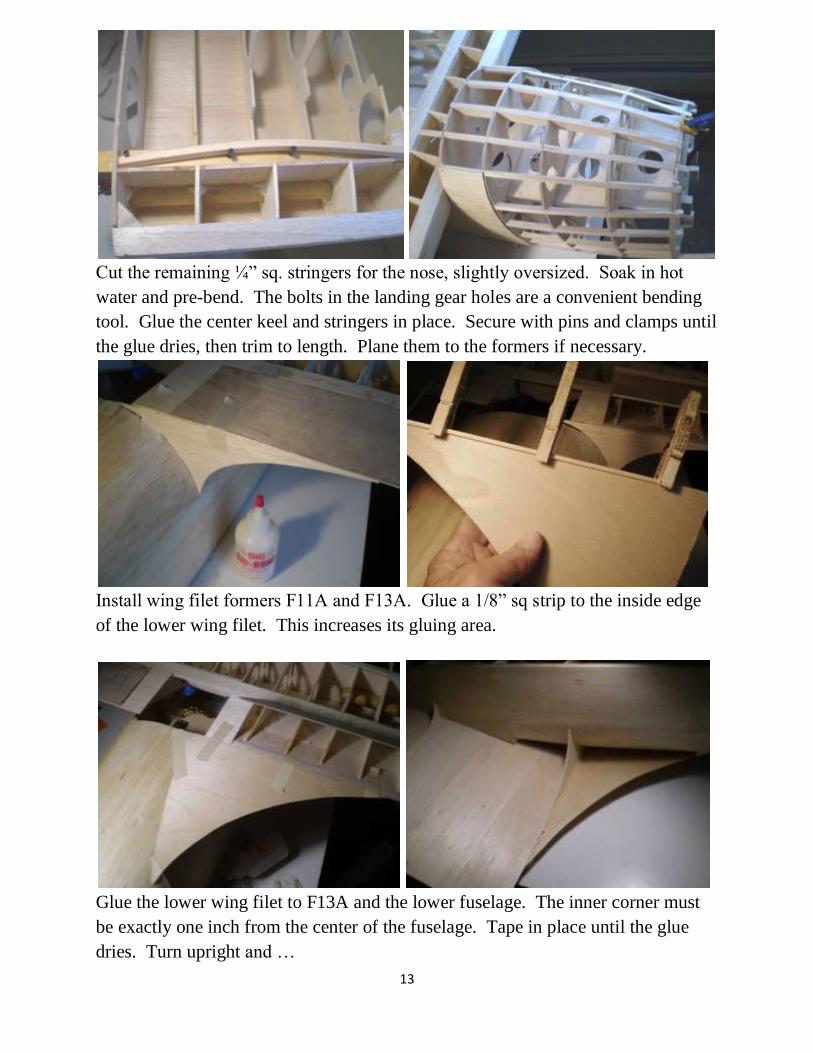
Glue the lower wing filet to F13A and the lower fuselage. The inner corner must
be exactly one inch from the center of the fuselage. Tape in place until the glue
dries. Turn upright and …

14
Glue the 1/64” ply middle upper wing filet to F11A, F13A and the upper wing
surface. Attach some 1/8” sq strips along the rear edge to support the rear filet.
Glue the lower 1/16” ply filet in place. Turn over and trim the upper edge to the
lower filet. Apply drywall spackle to the filet seams to feather to a smooth surface
before glassing.
Rough –cut the forward wing filet. Cover it with spackling compound. Sand to
final shape.

15
Feather the edges of the middle wing filet with spackle. Use your RC club
membership card as a spatula, then sand. Verify battery fit before attaching the
fiberglass chin cowl.
IMPORTANT: The fiberglass chin cowl is made about a ½” too long in order to
accommodate a variety of motors. For the motor shown, trim the rear edge of the
cowl so that the fiberglass cowl is 12-5/8” long. Alternatively, position the cowl
so that the distance from the center of F6 to the front edge of the cowl is 12-5/8”.
Or don’t trim the cowl in order to lengthen the nose by a non-scale ½ inch. (No one
will notice and your secret is safe with me.) For best alignment, install the motor
and spinner backplate, and place the cowl ¼” behind the backplate.
Lay the fiberglass cowl in place. Note how it is slightly transparent. Trace the
stringers and formers on the outside of the cowl with a pencil. Remove. Clean the
inside surface of the cowl with acetone or other oil-removing solvent. Apply slow-
cure epoxy or polyester resin to the stringers and formers with a disposable brush.
Also apply resin to the inside of the cowl using the tracings as a guide. Clamp,
tape and pin the cowl in contact with the stringers and formers.
16
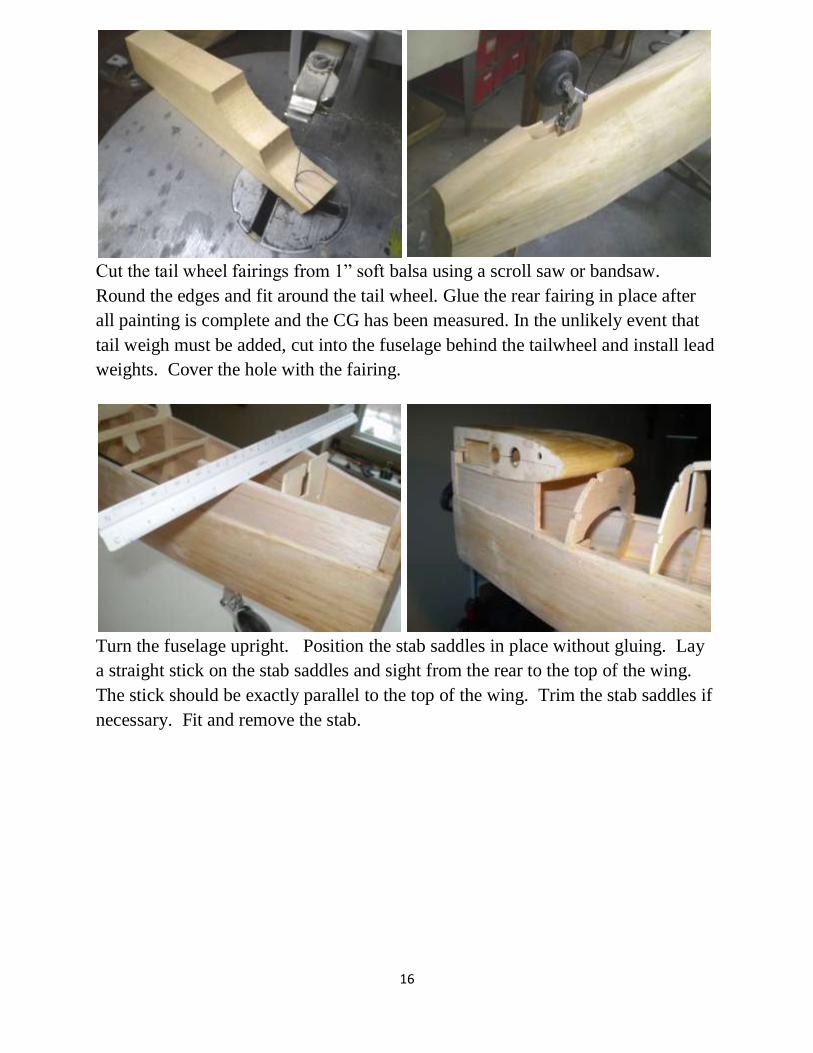
Cut the tail wheel fairings from 1” soft balsa using a scroll saw or bandsaw.
Round the edges and fit around the tail wheel. Glue the rear fairing in place after
all painting is complete and the CG has been measured. In the unlikely event that
tail weigh must be added, cut into the fuselage behind the tailwheel and install lead
weights. Cover the hole with the fairing.
Turn the fuselage upright. Position the stab saddles in place without gluing. Lay
a straight stick on the stab saddles and sight from the rear to the top of the wing.
The stick should be exactly parallel to the top of the wing. Trim the stab saddles if
necessary. Fit and remove the stab.

17
Bevel the upper forward corner of each stab saddle. Install stringers. Cut the stab
saddle skins (the pattern is on the plans) from 3/32” soft sheet. Wet the outside
surface with hot water, bend and tape in place without glue. Remove when dry.
The shape will be retained.
Glue the stab saddle skins in place.

18
Trim to final shape using the removable stab as a guide. Or use the one-piece stab
as a guide.
Install 3/32” aluminum tube rudder cable guides. Point them at the rudder servo.
Epoxy in place.
Epoxy the LiPo battery brackets in the nose. Epoxy hardwood ¼” sq stringers to
which the dummy exhausts will be attached. This area will also be an air exit for
the electric motor. It can be sheeted over for the gas engine version. Note how a
long ball driver can reach the lower electric motor bolts thru holes in the nose
formers.

19
Install F1 and nose stringers. Sheet the nose area from F6 forward.
Apply SaraWrap or waxed paper to the frame and glue the hatch formers and
stringers in place.
Install the hatch release mechanism before sheeting the hatch. Details 4 Scale
Hidden Latch System shown. In the event that the hex driver release fails, remove
the prop and spinner; push the pin back with a wire.
Lay Saran Wrap or other thin plastic or waxed paper on the frame to protect the
frame from glue, install the hatch and sheet the hatch while it is in place.

20
After installing and testing the rudder cables and elevator pushrod, epoxy the stab
in place. Cut away the cross-pieces of most of the rear formers to save weight.
They are no longer needed.
Epoxy the fin in place with the rudder attached for alignment. The leading edge of
the fin locks into a notch in F20. Glue and reinforce it with blocks (not shown).
Install the upper formers. Tilt formers F10 and F11 back 18° using the template on
the plans.

21
Fit and remove the pilot’s seat before completing stringer installation. All stringers
are ¼” square except the canopy base stringer from F10 to F13 which is 1/8” x
1/4”. If a sliding canopy is elected, the ¼” sq. brass canopy rail replaces this
stringer. The top three stringers between F12 to F14 should be hard balsa to resist
sagging.
Wet the outside surface of 3/32” sheet balsa with hot water and bend to the
fuselage shape. (Don’t wet both sides or else it will crack when it dries.) Glue it
to the fuselage frame and hold it in place with tape, T-pins, clothes pins, etc.
IMPORTANT: Use 4-6 lb lightweight contest grade sheet balsa aft of the cockpit.
If you don’t, the result will be severely tail-heavy. But use heavier, stiffer balsa
below the cockpit to avoid sagging between stringers.

22
Complete the sheeting of the fuselage. Balsa canopy rail increases the gluing area
for the canopy. Alternatively, a sliding canopy rail can be installed.
Shape the headrest area as shown. Fill holes with spackling as needed. Using the
canopy, trace the outline of the windscreen. Cut away excess material behind the
windscreen where the instrument panel will be mounted.
Removable antenna mast is 1/16” ply base between 2 layers of 1/8” balsa. Ply tab
on base inserts into slot in ply and balsa block. Glue the block to the back of F14.
Using the templates on the plans, mark the stringer locations at positions F13 and
F19.

23
Draw the stringer positions between F13 and F19 with a straight edge and a fine
felt-tip pen. To avoid confusion, start with the centerline (at crutch) and work
upward and downward. Then lay 1/32” or 1/16” (identical results) masking tape
over these lines before glassing. This will create a slight bulge to simulate
stringers. More than 80 feet of tape is required! Note that the Koku-Fan and Nye
drawings show stringers on the bottom of the fuselage but photos are vague at best,
e.g., Aero Detail 12.
Cover with ¾ oz glass cloth and resin. After painting, stringers should
Apply Klass Kote primer with a mini roller, look like this.
sand with 150 grit.
Another method, developed by Jeff
Quesenberry, uses 3/32” sheeting plus
1/32” balsa strips instead of 1/8”
sheeting in the rear fuselage. This
method is intended for covering with
iron-on fabric which is thicker than
fiberglass cloth.

24
Apply a filet of finishing resin and
microballoons with a palette knife to the
tail-fuselage junction. Sand smooth.
This fills remaining gaps and adds
strength.
Using the fuselage former patterns F8 &
F18, make a fuselage cradle. Line with window
A/C foam. Use it to hold the fuselage while
working on the bottom. Sanding the first coat
of primer on the fuselage requires about 6 hours
of work but the results are worth it.
Assemble the 6 exhaust stacks, 3 on each side. Cut ¾” deep slots to fit formers
and stringers. Glue in place after painting. Space around stacks provides cooling
for the electric motor and batteries that may not be necessary for the gas engine
version.

25
Choose or make an oil cooler air scoop. Use it to construct the fairing under the
chin (see Carburetor Air Scoop Installation notes).
Install the ventral fin and seal it with filler. Complete the exhaust stack installation.
Complete the tail fairings by masking off the tail fairing area. Apply light weight
spackling compound in thin layers to prevent cracking, waiting for each layer to
dry before applying the next. Sand to shape. Re-apply masking tape. Harden the
surface by applying thin cyano adhesive. Lightly sand with 180 grit sandpaper.

26
Light weight glass cloth is applied with epoxy resin. After curing, the excess is
trimmed away with a razor blade.
Install wing filets by same method. Alternatively, cut the stab filet from 1/64” ply.
Pattern on plans.
Rivet plates are vinyl stickers ESC in its holder, ready to
from Callie Graphics. install in fuselage.

27
Fuselage Assembly--Gas Motor
Most of the fuselage construction is the same as for an electric motor so it is
covered in “Fuselage Assembly.” Only the exceptions for gas are described here.
Tank box wih removable firewall.
Mount ignition battery, ignition module and throttle servo on top of the tank box.
The removable hatch also provides access to the needle valves.
IMPORTANT: The fiberglass chin cowl is made about a ½” too long in order to
accommodate a variety of motors. For the motor shown, trim the rear edge of the
cowl so that the fiberglass cowl is 12-5/8” long.
If nose weight is required, attach a removable ¼” x 4” x 12” ply shelf to the top of
the tank box extending forward. Install lead duck decoy weights to this shelf.
Use a 6” Tru-Turn or Dave Brown P-51 spinner with lightening holes in
backplate for cooling.
Inverted gas engine mounting, removable upper hatch. Enlarged firewall for
105CC inline twin Quadra 52.
28
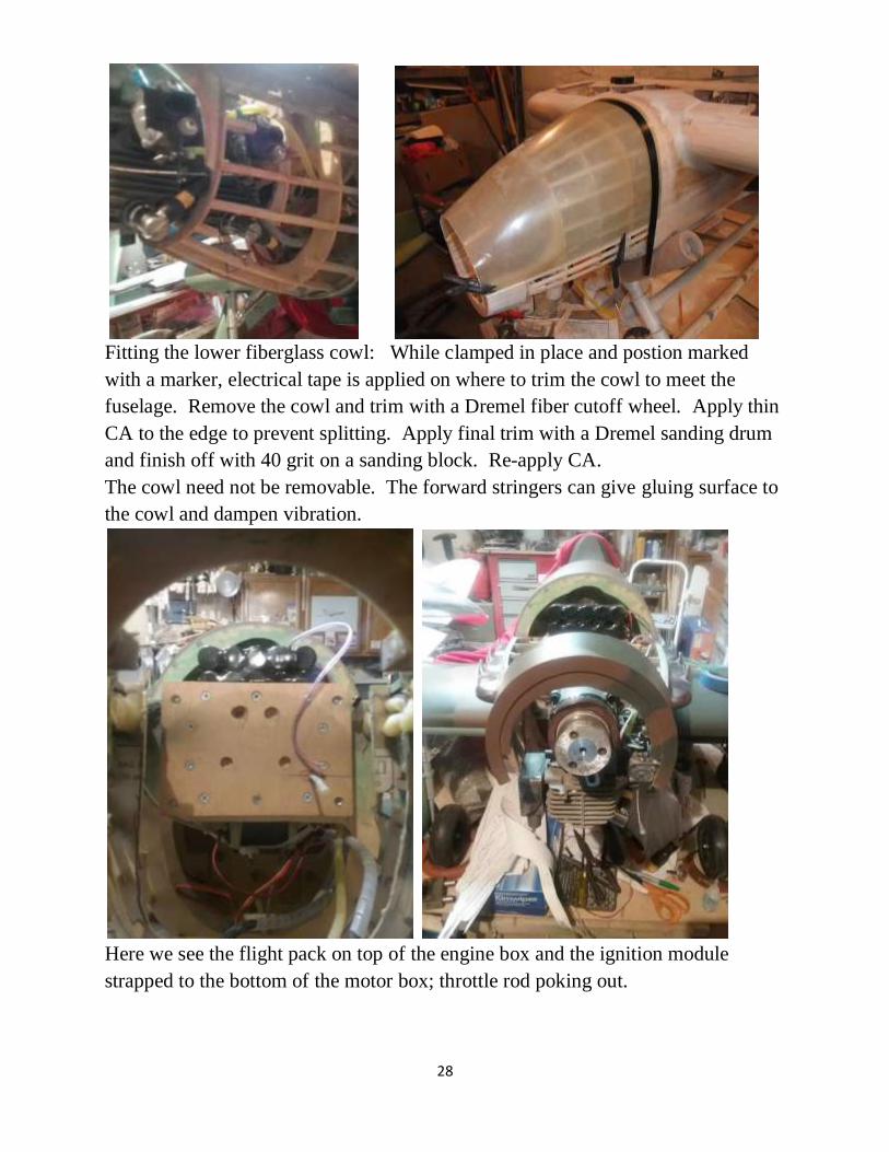
Fitting the lower fiberglass cowl: While clamped in place and postion marked
with a marker, electrical tape is applied on where to trim the cowl to meet the
fuselage. Remove the cowl and trim with a Dremel fiber cutoff wheel. Apply thin
CA to the edge to prevent splitting. Apply final trim with a Dremel sanding drum
and finish off with 40 grit on a sanding block. Re-apply CA.
The cowl need not be removable. The forward stringers can give gluing surface to
the cowl and dampen vibration.
Here we see the flight pack on top of the engine box and the ignition module
strapped to the bottom of the motor box; throttle rod poking out.

29
Radiator Construction
A fiberglass/polyester radiator is available from Micko Aircraft and Accessories.
See Parts List. Glue it to the ply radiator base with polyester resin. Speakers can be
installed like the wooden version. The following describes the construction of the
wooden version.
The radiator is constructed from light-weight balsa and ply. Lightweight
balsa is preferred in order to save weight and to ease carving. The radiator is
removable via four ¼ x 20 nylon bolts. This provides access to the tail servos and
perhaps other radio gear.
The electric version includes two 4” speakers that emit the recorded sound
of a Merlin engine, one facing forward and down, the other facing rearward and
down. This optimizes the audio for fly-bys.
The gas version provides a path for engine cooling air to pass over the top of
the wing inside the fuselage and exiting thru the rear opening in the radiator. The
front of the radiator is left open in order to increase a vacuum in the radiator via the
venturi effect.
30
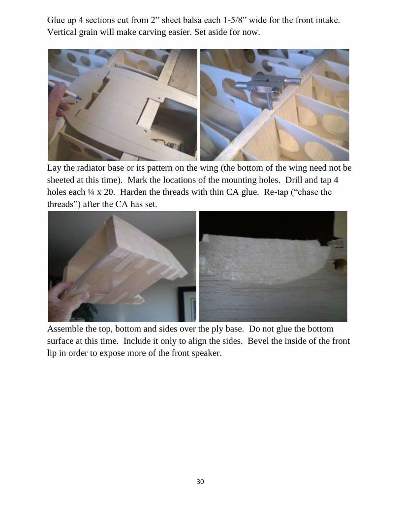
Glue up 4 sections cut from 2” sheet balsa each 1-5/8” wide for the front intake.
Vertical grain will make carving easier. Set aside for now.
Lay the radiator base or its pattern on the wing (the bottom of the wing need not be
sheeted at this time). Mark the locations of the mounting holes. Drill and tap 4
holes each ¼ x 20. Harden the threads with thin CA glue. Re-tap (“chase the
threads”) after the CA has set.
Assemble the top, bottom and sides over the ply base. Do not glue the bottom
surface at this time. Include it only to align the sides. Bevel the inside of the front
lip in order to expose more of the front speaker.
31
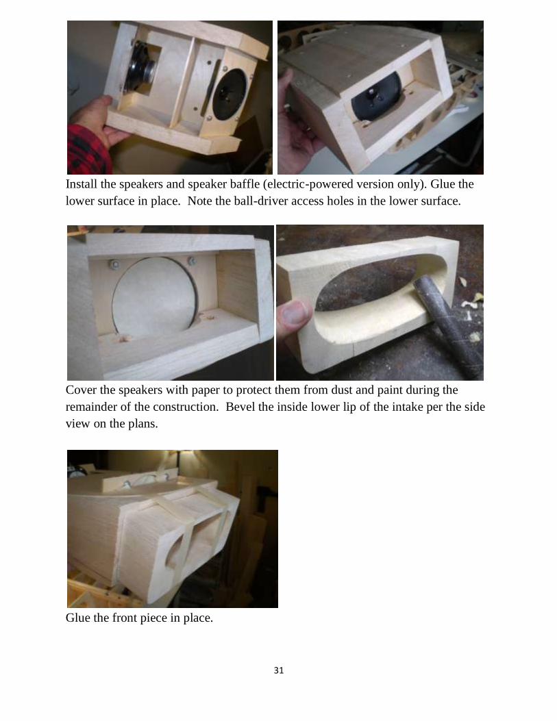
Install the speakers and speaker baffle (electric-powered version only). Glue the
lower surface in place. Note the ball-driver access holes in the lower surface.
Cover the speakers with paper to protect them from dust and paint during the
remainder of the construction. Bevel the inside lower lip of the intake per the side
view on the plans.
Glue the front piece in place.

32
Trim the corners of the speaker supports flush with the radiator base in order to
clears ribs 2.
Fit the radiator to the wing, insert a ball driver and verify that all four nylon bolts
align, and the radiator lays on the wing without gaps. Trim and shim if necessary.
Remove.
Cover the inside of the speakers with masking tape to keep out dust. The radiator is
now ready for final shaping by rounding the edges. Use the ply base, the fuselage
side view on the plans and photos of the full-sized as guides. Plane the sides flat
to match the views and photos, then round the edges. Let’s begin…
33
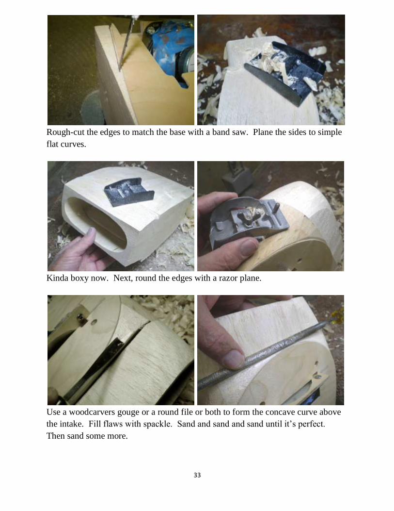
Rough-cut the edges to match the base with a band saw. Plane the sides to simple
flat curves.
Kinda boxy now. Next, round the edges with a razor plane.
Use a woodcarvers gouge or a round file or both to form the concave curve above
the intake. Fill flaws with spackle. Sand and sand and sand until it’s perfect.
Then sand some more.

34
Completed radiator, ready for glassing.
The entire radiator can be covered with one piece of ¾ oz glass cloth.
If ya did a good job, it should look like this.

35

36
Oil Cooler Intake Scoop Construction
A fiberglass oil cooler scoop is available. See the Parts List. But if you wish to
carve your own, it can be done by using the “lost wax” process. We carve a core
from balsa or foam, cover it with 3 layers of 6 oz fiberglass cloth and then remove
the core. Let’s begin.
Apply the top views and side views to a balsa block. Cut the top view with a scroll
saw of bandsaw and spot-glue the peices back in place.
Cut the side view with a bandsaw. Break the pieces apart.

37
Draw or paste the front view. Round the edges using an X-Acto knife,
sanding spindle tube, sanding block and sanding paper, using a
photo of the full-sized as a guide. Apply fiberglass covering.

38
One can quit here and use the balsa scoop or apply 3 more layers of 6 oz cloth.
Sand the surface. Drill out most of the core. Add primer. After sanding, ready for
color.
Alternatively, a fiberglass air scoop is available from Micko Aircraft and
Accessories.
And a 3D printed airscoop is available from Trapezoid Consulting, Inc.

39
3D printed air scoop available from
Kirk Schneider
Trapezoid Consulting, Inc.
629 Tupelo Way
Chaska, MN 55318
m952 356 6576
www.Trapezoid.co
40
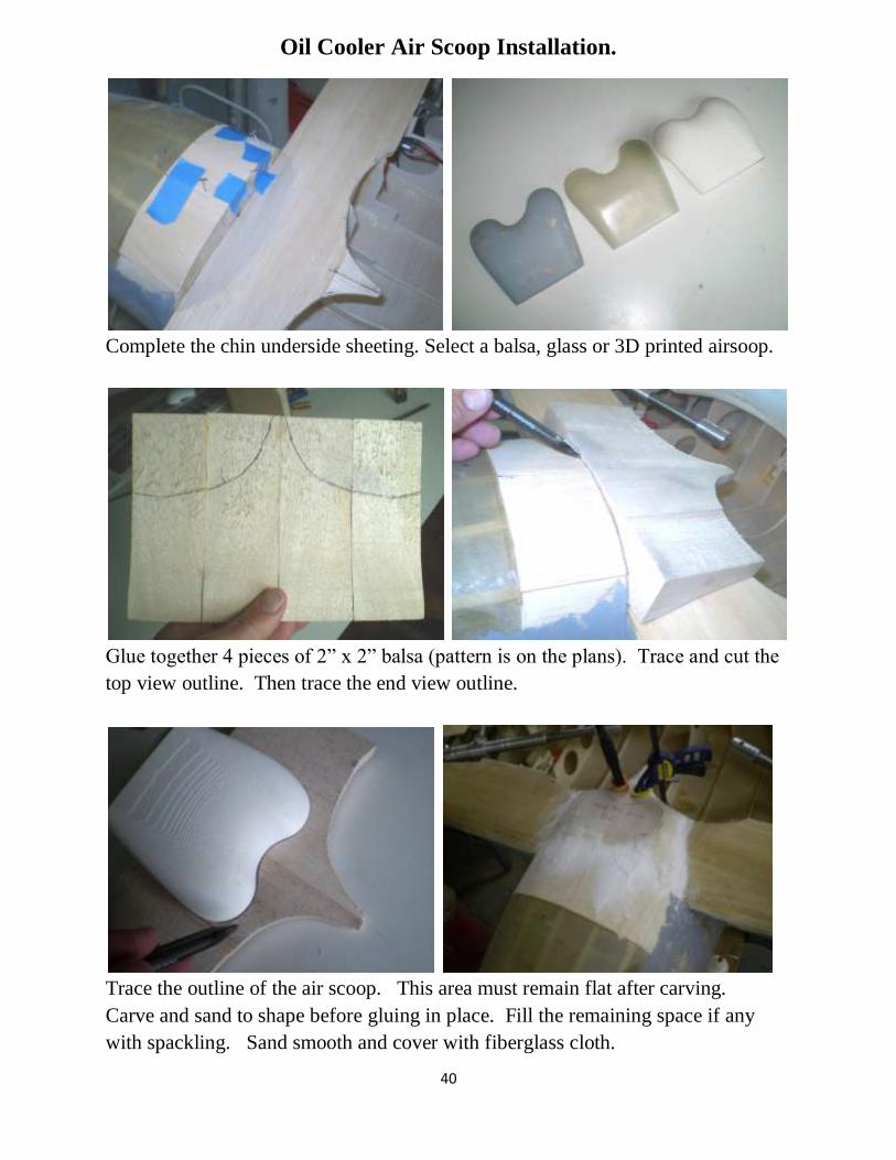
Oil Cooler Air Scoop Installation.
Complete the chin underside sheeting. Select a balsa, glass or 3D printed airsoop.
Glue together 4 pieces of 2” x 2” balsa (pattern is on the plans). Trace and cut the
top view outline. Then trace the end view outline.
Trace the outline of the air scoop. This area must remain flat after carving.
Carve and sand to shape before gluing in place. Fill the remaining space if any
with spackling. Sand smooth and cover with fiberglass cloth.
41
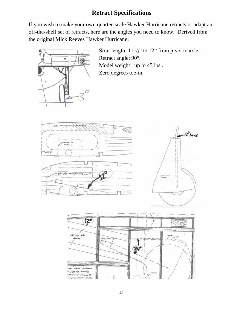
Retract Specifications
If you wish to make your own quarter-scale Hawker Hurricane retracts or adapt an
off-the-shelf set of retracts, here are the angles you need to know. Derived from
the original Mick Reeves Hawker Hurricane:
Strut length: 11 ½” to 12” from pivot to axle.
Retract angle: 90°.
Model weight: up to 45 lbs..
Zero degrees toe-in.

42
Flaps Assembly
The flaps are Maynard Method flaps construction -- a core of 3/32” sheet balsa
between two layers of 1/64” plywood, glued together with epoxy finishing resin.
The hinges are sandwiched between the outer (lower) layer of ply and recessed into
the balsa core. This combination has proven to be strong and warp-free.
Using the patterns on the plans, draw the flap skin outlines on a sheet of 1/64 x 12
x 24 ply. Note that the upper flap skins are ½” shorter in chord than the lower flaps
skins so that the flaps’ trailing edges can be tapered. Attach to a second sheet of
ply with double-faced tape. Cut out the flap skins with a straight edge and a
single-edge razor blade. Also cut out the flap cores from 4-inch wide balsa sheet.
Apply a light coat of oil with a Q-tip to the hinge pins of 20 DU-BRO Heavy Duty
hinges as a precaution against epoxy entering the hinge joints. Wipe off any
excess.
Using a DU-BRO hinge as a pattern, draw the outline of the hinges on the 3/32”
balsa flap core at the positions shown on the plans. Score the lines with a razor
blade for a clean cut and mill the balsa at each hinge position to a depth equal to
the thickness of the hinge body. Use a Dremel router bit in a drill press.
Experiment on a scrap piece of balsa to get the depth just right before cutting the
flap cores. If you enjoy woodworking, you will experience woodworking ecstasy.

43
Verify that the hinge fits flush with the surface of the hinge core. Epoxy the hinge
in place while being careful to not get glue into the hinge pin. Hold each hinge in
place with a clothes pin until the epoxy sets. Using one of those unsolicited credit
cards that we get in the mail, squeegee some more epoxy over the hinge to make a
flat, flush surface.
Spread a thin layer of finishing epoxy resin to the lower surface of the flap core
and the surface of the flap skin. Join together on a flat surface with lots of weights.
Cure overnight.
Bevel the last ½ inch of the trailing edge of the balsa core with a razor plane. Glue
the upper surface in place with finishing resin. Note that the upper flap surface is
½” shorter in chord for this reason.
Cut three 1” wide strips of 1/8” sheet balsa equal in length to the inner wing panel
and the lengths of the flaps in the outer panels. Recess and epoxy the flap hinges
into the balsa strips. Cover the flap pins with masking tape and apply a layer of
epoxy and microballoons over the exposed hinges with a credit card squeegee.
When cured, sand smooth.
44
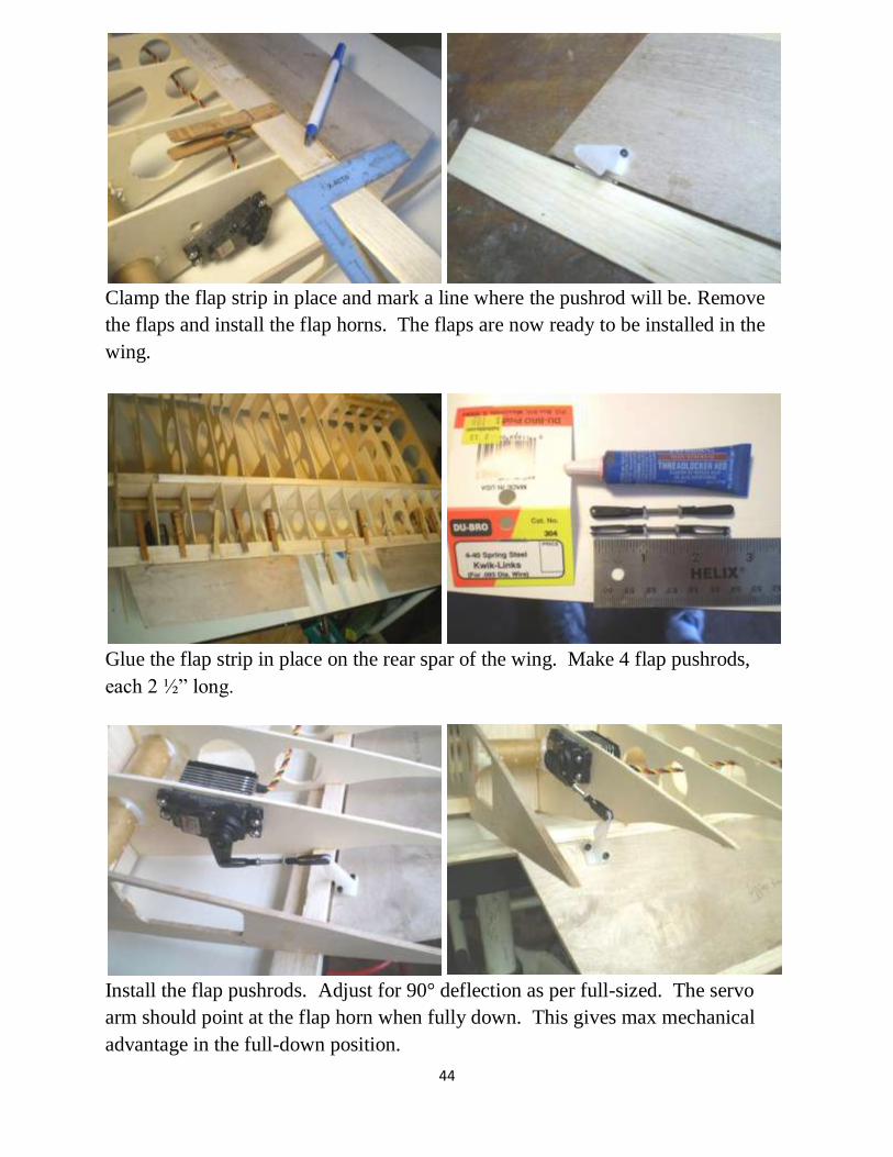
Clamp the flap strip in place and mark a line where the pushrod will be. Remove
the flaps and install the flap horns. The flaps are now ready to be installed in the
wing.
Glue the flap strip in place on the rear spar of the wing. Make 4 flap pushrods,
each 2 ½” long.
Install the flap pushrods. Adjust for 90° deflection as per full-sized. The servo
arm should point at the flap horn when fully down. This gives max mechanical
advantage in the full-down position.

45
Note that the full-sized Hurricane used 90° deflection on landing. But this
required full up-elevator to flair. Roy Vaillencourt (see References) recommends
only 30° deflection with power on and not attempting 3-point landings. The best
flap angle depends on your skill level.
Flaps extended 90° for landing.
46
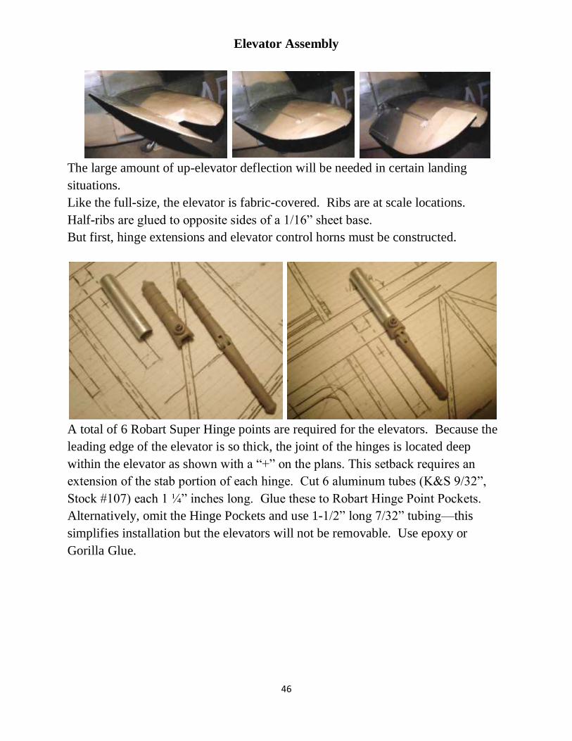
Elevator Assembly
The large amount of up-elevator deflection will be needed in certain landing
situations.
Like the full-size, the elevator is fabric-covered. Ribs are at scale locations.
Half-ribs are glued to opposite sides of a 1/16” sheet base.
But first, hinge extensions and elevator control horns must be constructed.
A total of 6 Robart Super Hinge points are required for the elevators. Because the
leading edge of the elevator is so thick, the joint of the hinges is located deep
within the elevator as shown with a “+” on the plans. This setback requires an
extension of the stab portion of each hinge. Cut 6 aluminum tubes (K&S 9/32”,
Stock #107) each 1 ¼” inches long. Glue these to Robart Hinge Point Pockets.
Alternatively, omit the Hinge Pockets and use 1-1/2” long 7/32” tubing—this
simplifies installation but the elevators will not be removable. Use epoxy or
Gorilla Glue.

47
Bend two elevator horn wires. (Breiten wire bender shown.) Clamp them in a vise
and file a flat on each to receive the set screw of a SIG nose gear steering arm.
Note the forward rake. This provides more up-travel than down-travel and
clearance of the rudder post.
SIG SH102 5/32” Nylon Steering Arm. Assemble the elevator over the plans.
Note the forward rake.
48
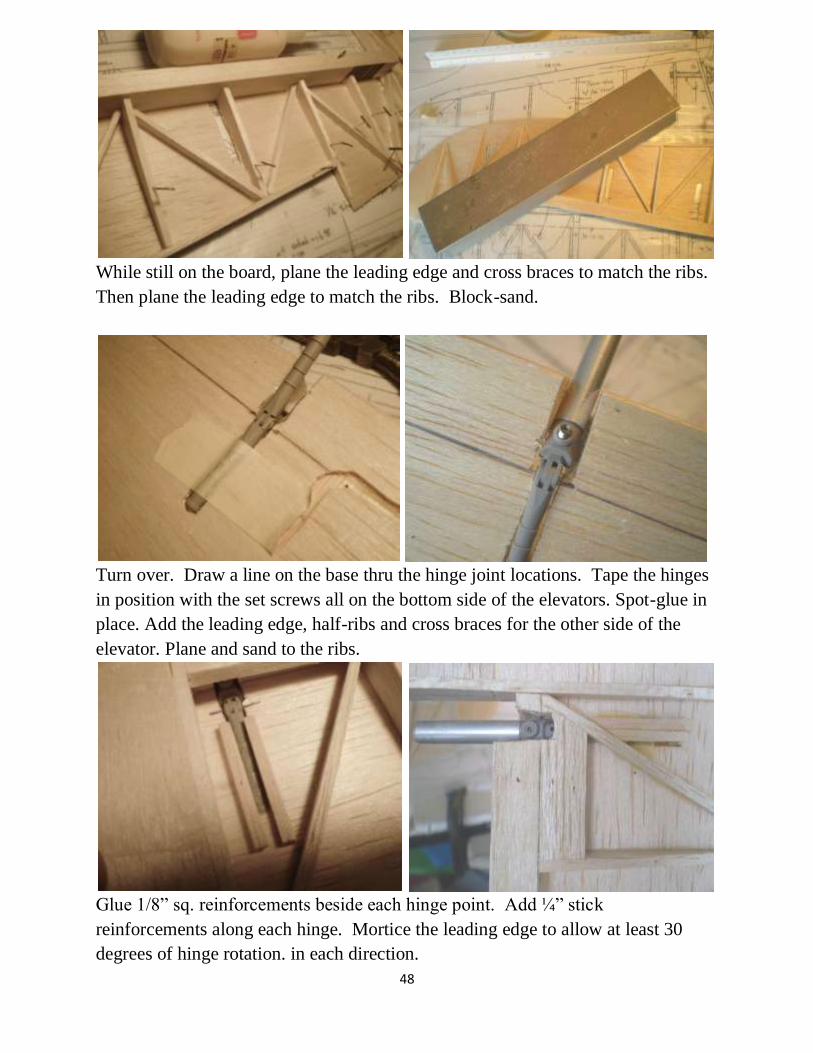
While still on the board, plane the leading edge and cross braces to match the ribs.
Then plane the leading edge to match the ribs. Block-sand.
Turn over. Draw a line on the base thru the hinge joint locations. Tape the hinges
in position with the set screws all on the bottom side of the elevators. Spot-glue in
place. Add the leading edge, half-ribs and cross braces for the other side of the
elevator. Plane and sand to the ribs.
Glue 1/8” sq. reinforcements beside each hinge point. Add ¼” stick
reinforcements along each hinge. Mortice the leading edge to allow at least 30
degrees of hinge rotation. in each direction.
49
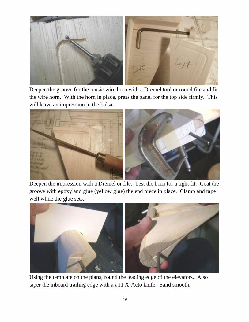
Deepen the groove for the music wire horn with a Dremel tool or round file and fit
the wire horn. With the horn in place, press the panel for the top side firmly. This
will leave an impression in the balsa.
Deepen the impression with a Dremel or file. Test the horn for a tight fit. Coat the
groove with epoxy and glue (yellow glue) the end piece in place. Clamp and tape
well while the glue sets.
Using the template on the plans, round the leading edge of the elevators. Also
taper the inboard trailing edge with a #11 X-Acto knife. Sand smooth.

50
The elevators are now ready to be mated with the stab and covered with fabric such
as SIG Koverall.
51
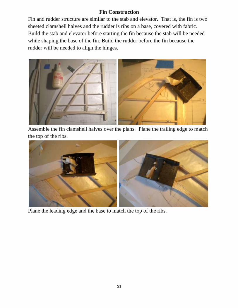
Fin Construction
Fin and rudder structure are similar to the stab and elevator. That is, the fin is two
sheeted clamshell halves and the rudder is ribs on a base, covered with fabric.
Build the stab and elevator before starting the fin because the stab will be needed
while shaping the base of the fin. Build the rudder before the fin because the
rudder will be needed to align the hinges.
Assemble the fin clamshell halves over the plans. Plane the trailing edge to match
the top of the ribs.
Plane the leading edge and the base to match the top of the ribs.

52
Sheet the fin with 4-inch wide 1/16” balsa. Cut the sheets so that the seams meet
on the spars.
Trim each fin half to the contour of the stab center section. The front portion must
be beveled. It is easier to do this before joining the fin halves so that the interior
can be seen.
Lay the rudder hinges on the fin’s trailing edge and mark their positions. Then file
a semicircular groove in each location to match the hinge pockets.
53
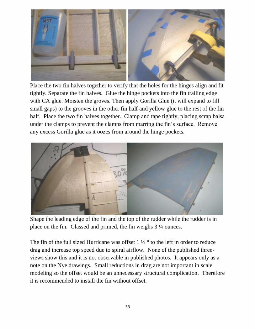
Place the two fin halves together to verify that the holes for the hinges align and fit
tightly. Separate the fin halves. Glue the hinge pockets into the fin trailing edge
with CA glue. Moisten the groves. Then apply Gorilla Glue (it will expand to fill
small gaps) to the grooves in the other fin half and yellow glue to the rest of the fin
half. Place the two fin halves together. Clamp and tape tightly, placing scrap balsa
under the clamps to prevent the clamps from marring the fin’s surface. Remove
any excess Gorilla glue as it oozes from around the hinge pockets.
Shape the leading edge of the fin and the top of the rudder while the rudder is in
place on the fin. Glassed and primed, the fin weighs 3 ¼ ounces.
The fin of the full sized Hurricane was offset 1 ½ ° to the left in order to reduce
drag and increase top speed due to spiral airflow. None of the published three-
views show this and it is not observable in published photos. It appears only as a
note on the Nye drawings. Small reductions in drag are not important in scale
modeling so the offset would be an unnecessary structural complication. Therefore
it is recommended to install the fin without offset.

54
After installing the fin, mask off the LE panel line and spray primer. Lightly sand.
Then apply rib stitching, Dynamic Balsa rib tape and leading edge tape.

55
Rudder Construction
Assemble the leading edge and ribs over the 1/8” sheet base. Turn it over and add
the leading edge and ribs to the other side. Easy.
Fit and remove the 1/16” aluminum rudder horn. Trim the horn for a tight fit.
Round the leading edge with a razor plane and a sanding block. Test the shape with
a 1-1/8” diameter template.

56
Sand the ribs to a uniform height with a sanding block. Round the bottom as
shown.
Do not shape the top of the rudder at this time. Wait until it is attached to the fin.
Mark the hinge lines ½” from the leading edge. Drill a 3/16” diameter hole at
each hinge location.
Using a #11 Xacto knife and a file, shape each hinge hole allow the Robart hinge
to swing at least 60° in each direction.

57
Glue the hinges in place with yellow glue. When dry, enclose each hinge with ¼”
square balsa on both sides.
Install the rudder horn after shaping the rudder leading edge. Reinforce with balsa
and provide a surface to which the fabric will attach.
Apply SIG STIX-IT to one side of the rudder surfaces. Apply STIX-IT just to the
outside edge of the trailing edge and about ¼” of the trailing edge on the other
side. Iron on SIG Koverall. Turn over and iron the overlap to the other side.
Repeat for other side. Heat shrink the entire surface.

58
Cut a notch in the
rudder’s leading
edge for elevator
horn clearance, non-
removable stab only.
Simulate rib stitches with diluted white glue applied with a pinched 7/32”
aluminum tube.
Iron pinked-edge rib tape over the rib stitches. Seal the entire surface with nitrate
dope. Sand lightly.

59
Cut the tail-light parts from balsa and ply. Add small screws and a glass bead.

60
One-piece Non-removable Stab Assembly
Measure your car. Be sure the fuselage will fit. If not, consider a three-piece plug-
in stab (see Stab Assembly). But if the fuselage with a one-piece stab will fit...
Omit the twin servos. Mount a 200 in-oz (minimum) servo above the radiator (see
Fuselage Assembly). A one-piece stab saves 5 ounces, mostly in the tail.
One-piece stab or three-piece plug-in stab ? Extended Robart Super Hinge Point
A total of 6 Robart Super Hinge Points are required for the elevators. Because the
leading edge of the elevator is so thick, the joint of the hinges is located deep
within the elevator as shown with a “+” on the plans. This setback requires an
extension of the stab portion of each hinge. Cut 6 aluminum tubes (K&S 7/32”,
Stock #1112) each 1-1/2” inches long. Use epoxy or Gorilla Glue.
Slide two DU-BRO 5/32” nose gear steering arms onto 5/32” music wire. Bolt a 4-
40 ball link between them with washers on either side.
Bend the rod ends 6 ½” apart. Breiten coil bender shown.

61
Move the dual steering arms close to the center of the wire. Rotate them so that
the arms will tilt slightly forward. This will provide more up-elevator than down
elevator plus proving greater clearance ahead of the rudder. File a flat on the wire
perpendicular to the set screws in the arms. Move the elevator arms to the center
of the rod, apply permanent thread locker and tighten the set screws.
The elevator horn is now ready to install in the elevator. Set it aside for
now.
Assemble both elevator halves over the plans. Turn them over and route the
groove to fit the elevator horn wire. Epoxy it in place.
Press the balsa end piece onto the elevator
horn wire so that it leaves an impression.
Route a groove in the impression. Add epoxy
and assemble the bottom halves of the
elevators the top halves. Round and shape the
elevators with a razor plane and sanding
block as shown in Elevator Assembly.

62
Assemble the stab half over the plans. Omit rib 1b. Cut rib 1a from 1/8” lite ply or
hard balsa instead of birch ply. Omit alignment dowels, tubes and sockets. Plane
the spars to match the ribs. Add 3/32” sheet shear webs to rib 4, vertical grain,
along the main spar.
Sheet the stab with 1/16” sheet balsa. Make two clam shell halves—one will be
the upper half and the other will be the lower half. Sheet only one of them at this
time.
Install the hinges in the elevator. Reinforce. Then epoxy the hinges to the sheeted
half of the stab. Reinforce. Glue the as-yet unsheeted other clamshell in place.
63
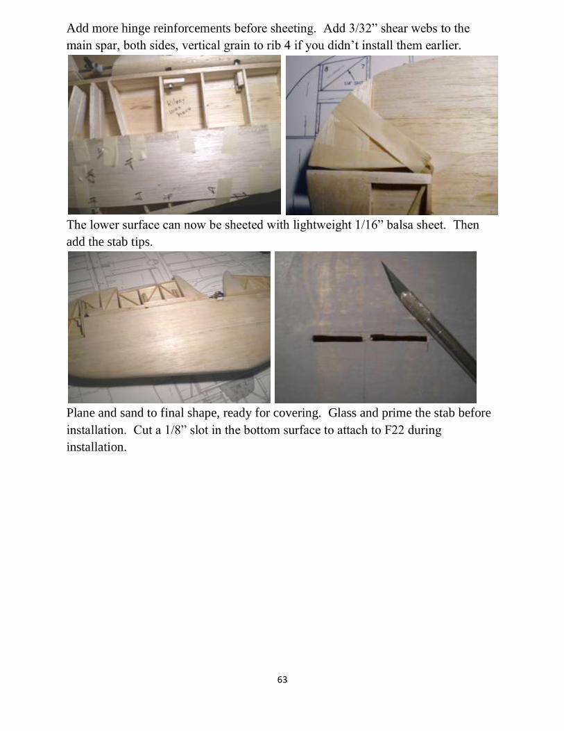
Add more hinge reinforcements before sheeting. Add 3/32” shear webs to the
main spar, both sides, vertical grain to rib 4 if you didn’t install them earlier.
The lower surface can now be sheeted with lightweight 1/16” balsa sheet. Then
add the stab tips.
Plane and sand to final shape, ready for covering. Glass and prime the stab before
installation. Cut a 1/8” slot in the bottom surface to attach to F22 during
installation.

64
Install a single carbon-fiber pushrod with a single 4-40 titanium or steel threaded
end into the ball link between the two steering arms before installation of the stab
into the fuselage.
If necessary, splice the pushrod by inserting a 3/32” x 1” brass tube epoxied in
place.
If you haven’t already done so, cut a notch in the rudder’s leading edge for elevator
horn clearance.

65
Removable Stab Assembly
The stab is built in three sections. (Optionally, it can be built in one piece—see the
notes on the plans and One-Piece Stab. A one-piece stab saves 5 ounces of weight,
mostly in the tail.) The outer sections are removable to allow the fuselage to fit
between the front seats of a compact car.
Construction can be simplified and a few ounces of weight saved in the tail
if the stab is constructed as one non-removable unit. To do this, build a one-piece
stab over the plans, cutting ribs from balsa instead of ply, omitting rib 1b, the guide
pins, the aluminum tube and socket. Note that a one-piece stab will not reduce total
weight very much because one or two long pushrods will be added.
The following discussion describes the three-piece option but most of it also
applies to the one-piece version.
The stab is built as clam-shell halves assembled over the plans. The top half
is slightly different than the bottom half. The top half contains guide pins to align
the stab. Two pins are included for redundancy and a tighter fit. The aluminum
tube is secured in place with field-removable socket-head bolts in the bottom
surface.
The lower surface is sheeted last, allowing internal access for reinforcement
of the sockets and hinges.
Elevator servos are installed in the outer stab panels. When assembled, the
arms, horns and pushrods are hidden inside the center section. By pushing the
elevator to fully down position, the horns and arms will fold upward to clear the
center section’s ribs when the panels are installed or removed.
The elevators will be needed about half way thru the construction process, so
it is recommended that they be built first.
Assemble the top half over the plans. Verify rib 1b is vertical with a draftsman’s
triangle. File the guide pin hole as needed to fit a ¼” dowel guide pin.

66
Glue the guide pins in place. Place a cap of lite ply over the pin at rib 2 to prevent
the pin from being accidently pushed inward during field assembly.
The trailing edge at ribs 1 and 2 is not quite tall enough due to the designer trying
to not waste wood (or perhaps due to his incompetence) so add a 1/4” x 1/8” scab
to the top of the trailing edge here.
Plane and block-sand the spar, trailing edge and leading edge to match the top of
the ribs.

67
Sheet the top half with 1/16” sheet balsa. Leave 1/8” overhang along the entire
trailing edge. Assemble the upper half of the opposite panel. Assemble the lower
halves too but don’t sheet them at this time.
Assemble the center section over the plans. Sheet only its top surface at this time.
Temporarily join the upper halves. Fit the guide pins and fit the phenolic sleeve.
Leave enough space between the ribs for a backless razor saw. X-acto blades will
do for spacers. Tape a straight stick to the trailing edge to level the three sections.
Spot-glue the sleeve in place.
68
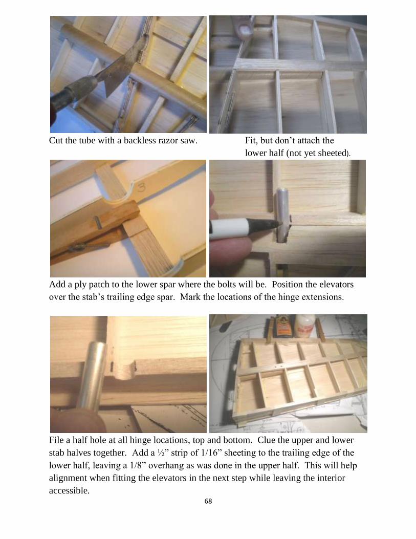
Cut the tube with a backless razor saw. Fit, but don’t attach the
lower half (not yet sheeted).
Add a ply patch to the lower spar where the bolts will be. Position the elevators
over the stab’s trailing edge spar. Mark the locations of the hinge extensions.
File a half hole at all hinge locations, top and bottom. Clue the upper and lower
stab halves together. Add a ½” strip of 1/16” sheeting to the trailing edge of the
lower half, leaving a 1/8” overhang as was done in the upper half. This will help
alignment when fitting the elevators in the next step while leaving the interior
accessible.

69
Fit, but don’t glue the elevators to the stab. Remove and attach temporary 1/16”
spacers to the stab trailing edge spar.
Epoxy the hinges to the stab while the elevator is pined in place. Remove the
elevators. Remove the spacers. Reinforce the hinges in the stab with ½” balsa. Pin
in place while Gorilla Glue sets. (It expands to fill gaps.)
Assemble the center section and both panels with the aluminum tube in place.
Drill and tap for two ½” x 8-32 socket head bolts in the underside of each panel.
(Two are included for safety.)
70
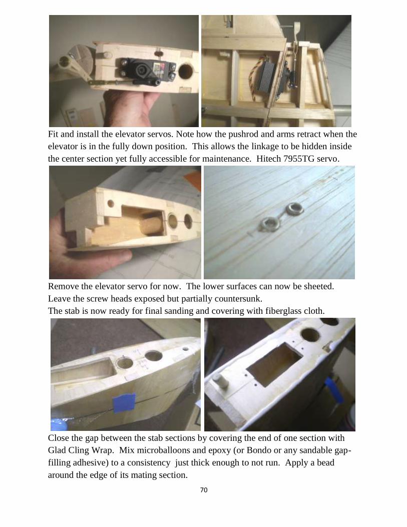
Fit and install the elevator servos. Note how the pushrod and arms retract when the
elevator is in the fully down position. This allows the linkage to be hidden inside
the center section yet fully accessible for maintenance. Hitech 7955TG servo.
Remove the elevator servo for now. The lower surfaces can now be sheeted.
Leave the screw heads exposed but partially countersunk.
The stab is now ready for final sanding and covering with fiberglass cloth.
Close the gap between the stab sections by covering the end of one section with
Glad Cling Wrap. Mix microballoons and epoxy (or Bondo or any sandable gap-
filling adhesive) to a consistency just thick enough to not run. Apply a bead
around the edge of its mating section.

71
Push the two sections together, squishing the sealant. Separate the sections
immediately just in case some of the goo got into the alignment pegs or the
aluminum tube. Let cure. Peel off the Cling Wrap. If any gap remains (chances
are it will). Repeat the process for the other surface.
After the seal has cured, peel away the Saran Wrap. Join the sections and sand
away any flashing.
Cut a 1/8” slot in the bottom of the stab behind the spar to accept the tab in F22.
The stab is now ready for mating with the fin and fuselage.

72
Wing Center Section Assembly
Cut out the ribs using the patterns on the plans. Stack 4 pieces of 1/8” ply and cut
out ribs 7 and 8 simultaneously in order to ensure they have exactly the same
shape.
Install the flaps servos into ribs 7.
Cut the lower front spar to length. Install blind nuts for the retracts. Note that
common hardware store ¾ x ¾ square “dowels” are slightly less than ¾”. If you
use one for the forward spar, adjust the rib notches to the actual size.
Install a rib alignment jig over the plans to elevate the TE of ribs approximately 2
inches. A T made from hardware store ¼” x 1 ¼” pine molding material will do.

73
Install ¾ x 3 x 36 LE over the plans while the TE of the ribs are supported.
Glue ribs 1 thru 7 in place (rib 8 later) to the LE, upright, over the plans with rib
ends elevated approximately 2 inches. Install the upper rib spars.
Turn over. Elevate TE about 2 inches. Remove the temporary section of rib 3.
Install the lower spars and fit one retract.

74
Clamp a straight stick to rib 8 to remove any warp. Install rib 8 with epoxy. Snug
it against the retract. Pin or tape in place. Remove the retract before the epoxy
sets. Clean any epoxy residue off the retract.
Bevel the rear retract support to clear sheeting. Drill holes in the rear spar for the
rear retract support. Install blind nuts under the rear spar. Repeat the above
process for the other retract.
Fill the gaps in the ribs below the lower spars with balsa sticks. Use scrap left over
from cutting the other balsa spars to length. This provides bonding for the
sheeting. Trim LE and other balsa spars flush with rib 8.
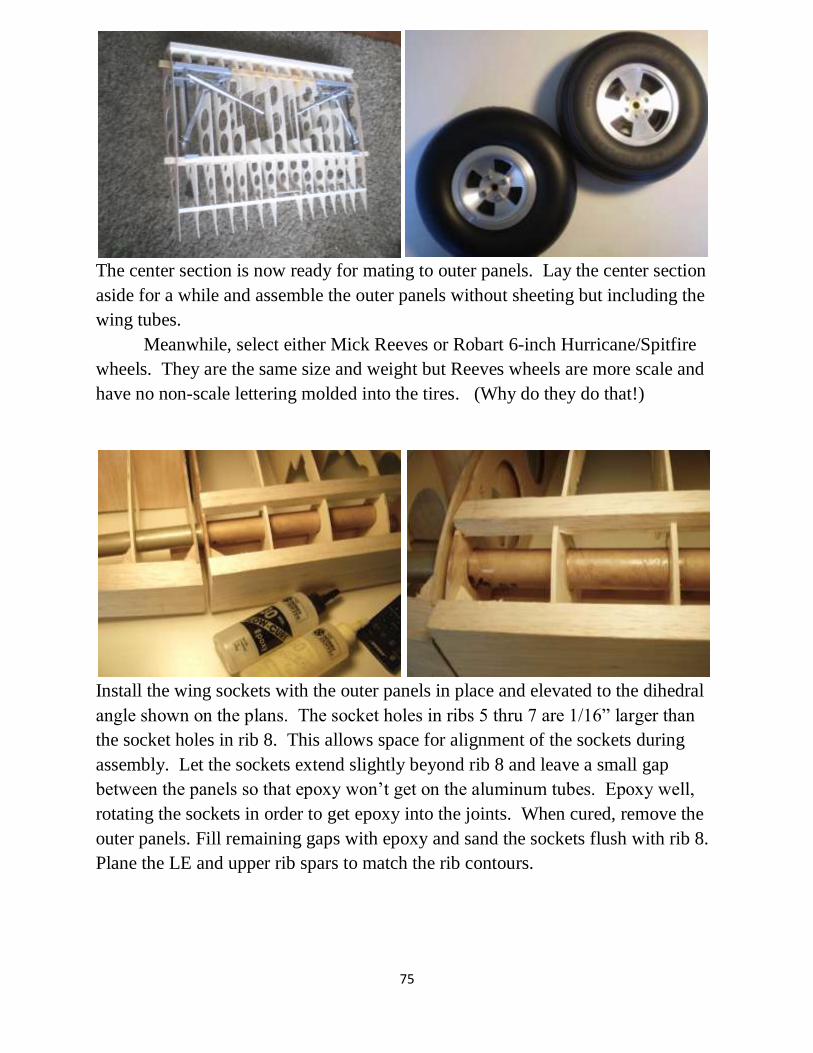
75
The center section is now ready for mating to outer panels. Lay the center section
aside for a while and assemble the outer panels without sheeting but including the
wing tubes.
Meanwhile, select either Mick Reeves or Robart 6-inch Hurricane/Spitfire
wheels. They are the same size and weight but Reeves wheels are more scale and
have no non-scale lettering molded into the tires. (Why do they do that!)
Install the wing sockets with the outer panels in place and elevated to the dihedral
angle shown on the plans. The socket holes in ribs 5 thru 7 are 1/16” larger than
the socket holes in rib 8. This allows space for alignment of the sockets during
assembly. Let the sockets extend slightly beyond rib 8 and leave a small gap
between the panels so that epoxy won’t get on the aluminum tubes. Epoxy well,
rotating the sockets in order to get epoxy into the joints. When cured, remove the
outer panels. Fill remaining gaps with epoxy and sand the sockets flush with rib 8.
Plane the LE and upper rib spars to match the rib contours.

76
Assemble the inner flaps (See Flap Assembly). Install the flaps and flap linkage.
Allow for 90° deflection as per full-sized. Note that the full-sized Hurricane used
90° deflection on landing. But this required full up-elevator to flair. Roy
Vaillencourt (see References) recommends only 30° deflection with power on and
not attempting 3-point landings.
Install the 1/8” sheet hard balsa shear webs. They are important for strength and
flutter prevention.

77
Drill and countersink holes for #6 x ½” wood screws in the bottom of the door
guides before cutting out the door guides with a scroll saw. Sand the hole for a
loose fit around the upper oleo strut, so that the door will ride up and down with
the axle.
Cut a pedestal for the Sierra Giant Scale ¾” strut collars from 3/8” ply. Counter
sink for 6-32 x ½” FH machine screws. Cut the counter sinks slightly oversized so
that 1/32” sheet aluminum will be drawn into the holes. A diameter of 1/16” larger
than the screw heads is about right. Apply epoxy to the bottoms of the guide and
clamp pedestals when attaching them to the doors.

78
Attach the guides and clamps to the 1/32” aluminum doors with 6-32 x ½” flat-
head machine screws. The aluminum will be drawn into the counter sink as the
screws are tightened.
The doors may now be fitted to the retracts already installed in the wing.
Temporarily place a piece of 1/8” sheet balsa near the doors to simulate sheeting.
The doors should rest slightly above the balsa surface, not in it, to avoid the risk of
jamming. Trim or shim the clamp and guides where they meet the door surface if
necessary. After fitting to the wing, putty (Bondo) may be applied over the screw
heads and sanded smooth.

79
Shape and fit balsa fairings to doors using photos as a guide. Glass and primer the
fairings before gluing them to the doors.
The wheel and axle are held in place by the bolt head on the end of the axle, an 8-
32 x ½” set-screw in the end of the strut and a 10-24 stop-nut on the end of the
axle. A ¼” DU-BRO wheel collar (set screw not needed) provides clearance
between the wheel hub and the door clamp. Apply grease to the bearing.
Fit the landing gear to the wing before sheeting the wing.
Turn over, support with lower surface alignment jig and sheet the upper surface
Attach the center section to the fuselage (see Fuselage Assembly).

80
Attach air line tubing to the retracts before final installation. Secure the
connections with either double-wrap soft wire clamps or Tom Cook plastic tubing
clamps (recommended).
Install a balsa strip to the lower inner edge of the outer rib to increase sheeting
gluing area. Add a 90° balsa wedgy (not shown on plans) to support the lower
sheeting in this area.
Spot-glue aileron and flap servo extension wires in the outer wing panels.
Complete the sheeting of the lower surface. It must be flat where the oil cooler
intake will be attached. Cut the wheel wells using the doors and wheels as a guide.
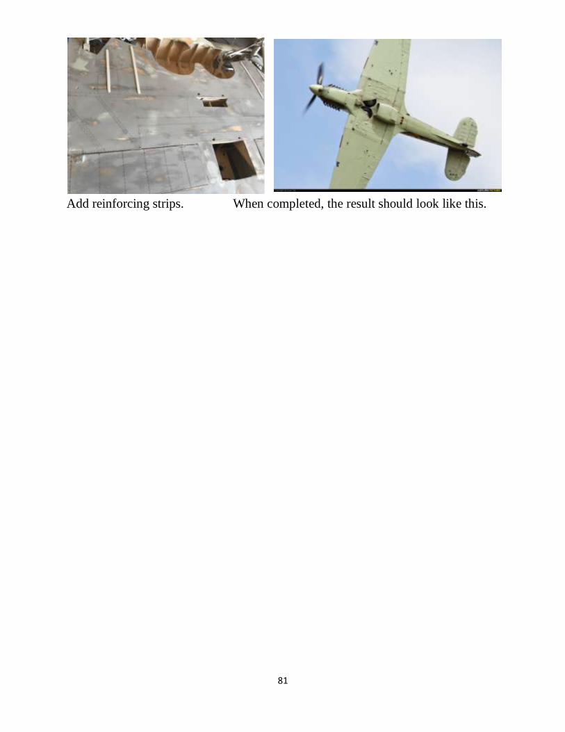
81
Add reinforcing strips. When completed, the result should look like this.

82
Outer Wing Panel Assembly Procedure
First, install the flap servos. If Spangenberg servo links (shown) are to be used,
install the aileron servos now too. File wing tube holes in ribs 8-11 for a snug fit.
Lay the lower mains spar flat on the plans. Install ribs 8-11 upright on the wing
tubes and place them on the plans, elevating the TE with the lower surface washout
stick. Spot-glue a couple of them to the washout stick. Verify a loose but snug fit
of the tubes. Don’t glue them in place yet.

83
Clamp a straight stick to rib 8 to remove all warps and make it straight. Tilt Rib 8
five degrees using the tilt template shown on the plans. Make a jig having two 7/8”
diameter holes spaced apart the same distance as the tube holes in Rib 8 (13 ¾
inches). Apply it to the end of the tubes to verify that the tubes are parallel.
Enlarge the holes in ribs 8-11 if necessary so that the jig fits the ends of the tubes.
Don’t glue the tubes yet.
Glue the other ribs to the lower mains spar. Pin sub rib 15 to rib 15 with a 1/16”
spacer. It will become the inner rib of the aileron. Elevate the end rib 21 so that it
aligns with rib 20.

84
Glue the upper spars in place. Install sheer webs in the main box spar. Vertical
grain. The sheer webs increase the strength of the box spar and they also make the
wing twist-resistant, increasing the flutter speed. This is a lot of work but it is
pleasant work and very important. Do a good job.
Install sheer webs in the rear spar but not next to the tube area in ribs 8-11 yet.
This makes the wing rigid so we can at last glue the wing tubes in place using lots
of slow-set epoxy. Apply the tube jig again to the tube ends to assure that the tubes
are parallel while the epoxy sets.
Wing ready to receive sheer webs next
to the rear wing tube. Note how the
flap servo is accessible thru the large
opening in rib 9.

85
Clamp the as-yet unshaped LE to the bench. This allows easy access to the aileron
hinge line. Add balsa hinge supports on the wing side of the aileron hinge line.
Use scraps left over from trimming the spars.
Lay ½” sheet balsa beside the aileron ribs and mark the length and width of each
section between the ribs. Cut the sections to length and fill the LE area of the
aileron with the ½” balsa. Leave a 1/32” gap using temporary spacers. Coffee
shop wooden stirring sticks work well. The gap leaves room for a razor saw to cut
the ailerons free in a later step.

86
Mark the location and angle of each Robart hinge position. Drill a 1/8” pilot hole
thru the aileron leading edge and the hinge supports in the wing. The pilot hole
will be used later to extend the holes for the Robart hinges. Plane the supports
flush with the ribs.
Add ½” hinge support blocks behind the aileron LE.
Trim the sockets and spar of of the ends of the main and outer panels flush with the
end ribs. Assemble and verify that the lower main spars fit into the holes in rib 9.
Enlarge the holes if necessary.
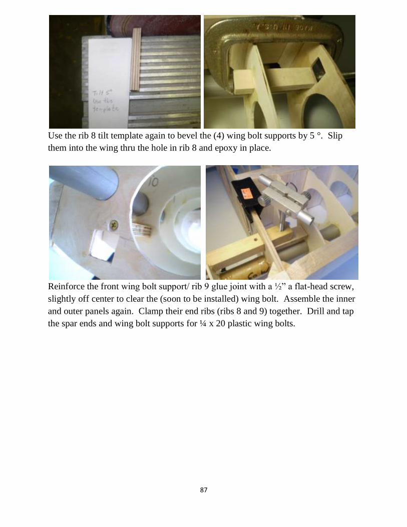
87
Use the rib 8 tilt template again to bevel the (4) wing bolt supports by 5 °. Slip
them into the wing thru the hole in rib 8 and epoxy in place.
Reinforce the front wing bolt support/ rib 9 glue joint with a ½” a flat-head screw,
slightly off center to clear the (soon to be installed) wing bolt. Assemble the inner
and outer panels again. Clamp their end ribs (ribs 8 and 9) together. Drill and tap
the spar ends and wing bolt supports for ¼ x 20 plastic wing bolts.

88
Trial-fit the wing bolts. Remove and separate the wing panels. Harden the threads
in the wing bolt supports with thin CA glue. When cured, “chase” the threads with
the tap again to remove the fuzz in the threads.
Secure each rear wing bolt support with a small flat-head wood screw.
Tack-glue the aileron servo cable to the ribs to prevent it from wearing in flight.
Stack 4 sheets of 1/8” balsa and cut the aileron skins.
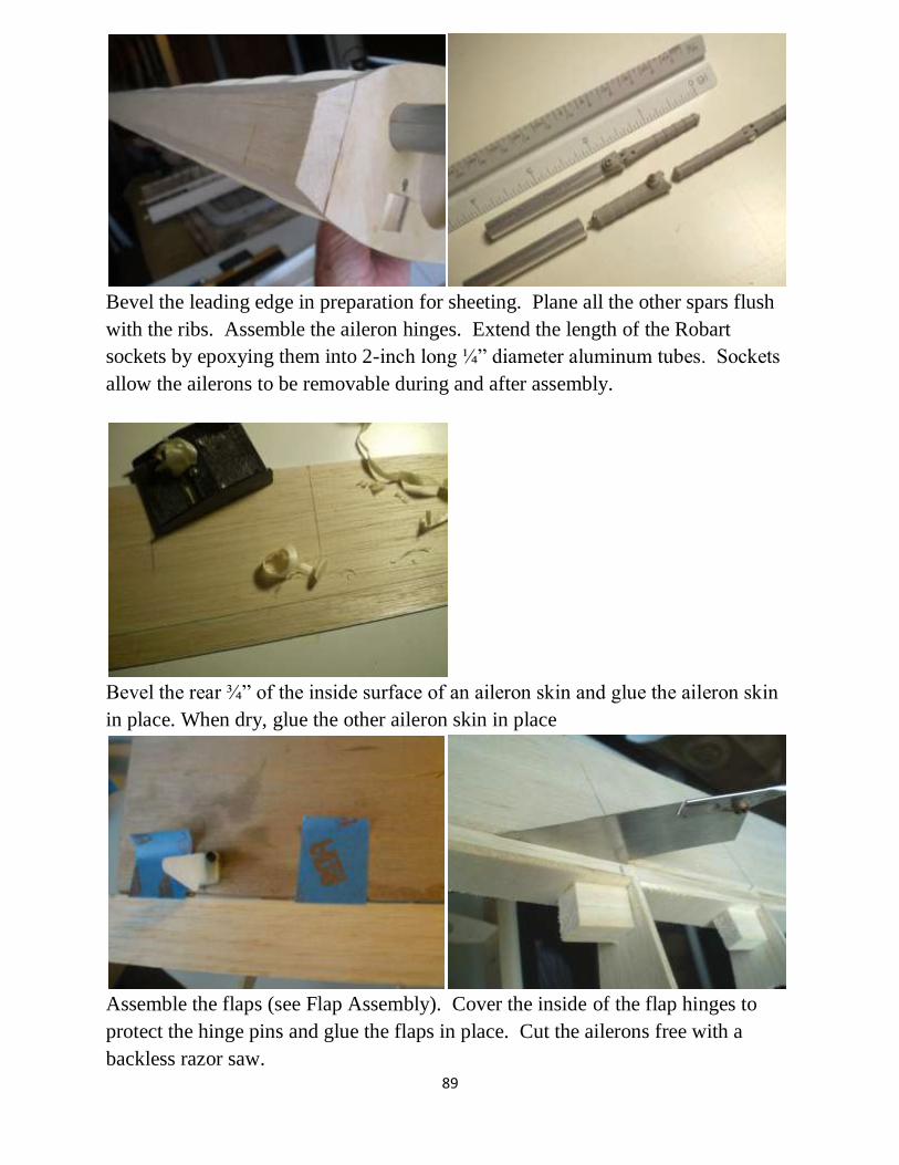
89
Bevel the leading edge in preparation for sheeting. Plane all the other spars flush
with the ribs. Assemble the aileron hinges. Extend the length of the Robart
sockets by epoxying them into 2-inch long ¼” diameter aluminum tubes. Sockets
allow the ailerons to be removable during and after assembly.
Bevel the rear ¾” of the inside surface of an aileron skin and glue the aileron skin
in place. When dry, glue the other aileron skin in place
Assemble the flaps (see Flap Assembly). Cover the inside of the flap hinges to
protect the hinge pins and glue the flaps in place. Cut the ailerons free with a
backless razor saw.

90
Mark the hinge lines and the radius of curvature on aileron and shape the leading
edge with a razor plane and a sanding block. Drill holes for the Robart hinges and
shape the opening to allow the hinge to swing ±45°. Glue the hinges in place with
epoxy or Gorilla Glue.
Cut away a rectangle of sheeting from
the lower surface of the aileron.
Install the aileron horn supported with
balsa blocks and epoxy. Then replace
the sheeting.
Enlarge the holes in the wing TE and trial-fit the ailerons in place. Adjust the
holes if necessary for a bind-free fit. Glue the hinge extensions in place with
epoxy or Gorilla Glue. The ailerons can be removed by loosening the set screws in
the hinge pockets.

91
The wing panels are now ready for
sheeting. Elevate the TE of an inverted
wing panel with the top surface washout
stick and verify the washout angle by
taping straight sticks to the end ribs. Sight
along them to verify that the washout
angle is 3 ½ degrees. Then sheet the
bottom surface.
Turn over, set the panel upright on the bottom surface washout stick. Verify the
washout angle again. Sheet the top surface. Plane and sand the surfaces flush with
the ailerons.
Mate the outer panel to the inner panel again. Trim and shim the junction with
balsa sheet. Remaining small gaps will be filled later after glassing.
Install the aileron servo tray support in place.
Cut LE for landing lights, both panels. Reflector is half ping-pong ball painted
with silver Krylon.
92
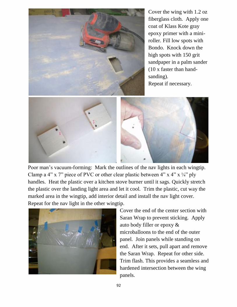
Cover the wing with 1.2 oz
fiberglass cloth. Apply one
coat of Klass Kote gray
epoxy primer with a mini-
roller. Fill low spots with
Bondo. Knock down the
high spots with 150 grit
sandpaper in a palm sander
(10 x faster than hand-
sanding).
Repeat if necessary.
Poor man’s vacuum-forming: Mark the outlines of the nav lights in each wingtip.
Clamp a 4” x 7” piece of PVC or other clear plastic between 4” x 4” x ¼” ply
handles. Heat the plastic over a kitchen stove burner until it sags. Quickly stretch
the plastic over the landing light area and let it cool. Trim the plastic, cut way the
marked area in the wingtip, add interior detail and install the nav light cover.
Repeat for the nav light in the other wingtip.
Cover the end of the center section with
Saran Wrap to prevent sticking. Apply
auto body filler or epoxy &
microballoons to the end of the outer
panel. Join panels while standing on
end. After it sets, pull apart and remove
the Saran Wrap. Repeat for other side.
Trim flash. This provides a seamless and
hardened intersection between the wing
panels.
93
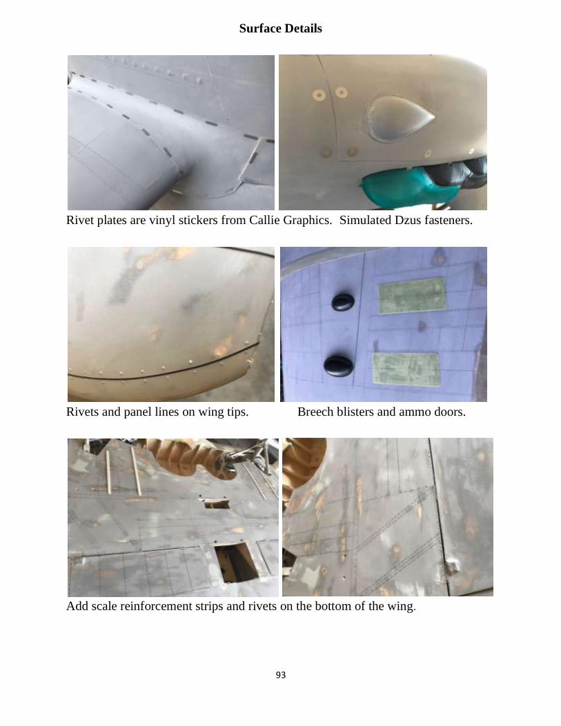
Surface Details
Rivet plates are vinyl stickers from Callie Graphics. Simulated Dzus fasteners.
Rivets and panel lines on wing tips. Breech blisters and ammo doors.
Add scale reinforcement strips and rivets on the bottom of the wing.

94
Draw invasion stripe with a carpenter’s laser. Mask per laser line and spray.
Attach Kirk Schneider gun shrouds and barrels. Compare to full-size.
Two-tone or one-tone bottom color scheme. Wingtip light.

95
Kirk Schneider landing light Wing joint cover is G10
First flight, Jeff Quesenberry, July 6, 2018, Owatonna Minnesota
Weight 51 lbs Nose weight 6 pounds
Dual inline Quadra 54s, 24 x 12 Zinger propeller
First flight video at
https://www.youtube.com/watch?v=CTIF5F_6FLs&feature=yout
u.behttps://www.youtube.com/watch?v=CTIF5F_6FLs&feature= youtu.be
References
This design is derived from the Koku Fan Hawker Hurricane drawing, catalog
number KF 4516.
Copies are available from Aircraft Documentation Services, http://www.airdoc.biz.
The plans were drawn by enlarging the following sections of the Koku Fan
drawings and filling in the structure.

96
Deviations from the Koku Fan drawings include the following:
--The wheel size (24-inches full size) was adjusted per measurements taken
of the full-size Hurricane in the Canadian Warplane Heritage Museum by Tony
Paladino.
--The airfoil was derived from the Willis Nye drawings because the Nye
airfoil better matched the photos.
For proof-of-outline in formal competition, the Koku Fan drawing KF 4516 is
recommended.
Details not included in the Koku Fan drawing
were derived from photos in these
publications:
Hurricane in Action, Squadron/Signal
Publications No. 72.
Aero Detail 12, Hawker Hurricane, RZM Imports, Dist.,
Available from http://www.rzm.com/books/model/aero.cfm

97
Also of interest:
Landing techniques re Roy Vailencourt’s 4.5 scale Hurricane:
http://www.vaillyaviation.com/images/Hurricane%20landing%20technique.pdf
https://doogsmodels.com/2016/05/24/review-132-fly-hawker-hurricane-mk-iic/
http://www.rcuniverse.com/forum/rc-warbirds-warplanes-200/11620728-dave-
andersen-1-4-scale-hawker-hurricane-2.html
http://www.militaryaviationmuseum.org. Virginia Beach, VA, (757) 721-7767

98

99
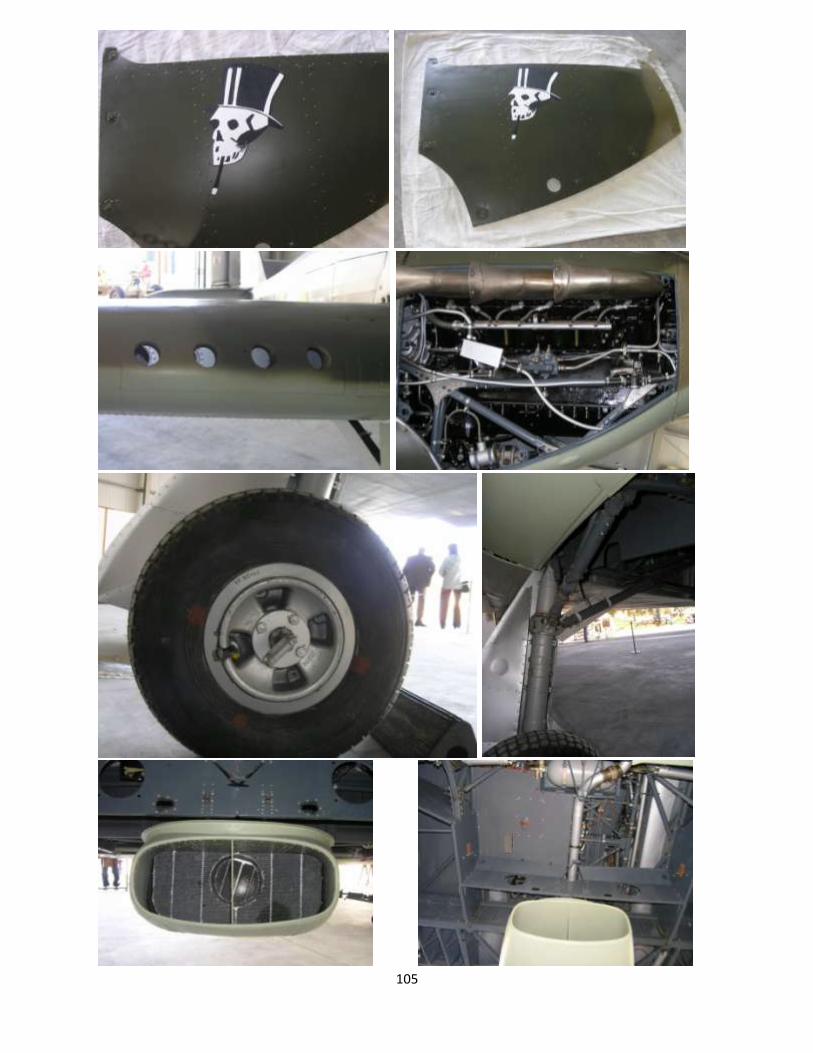
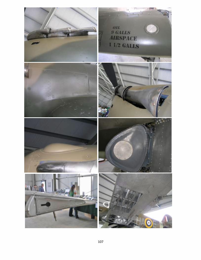
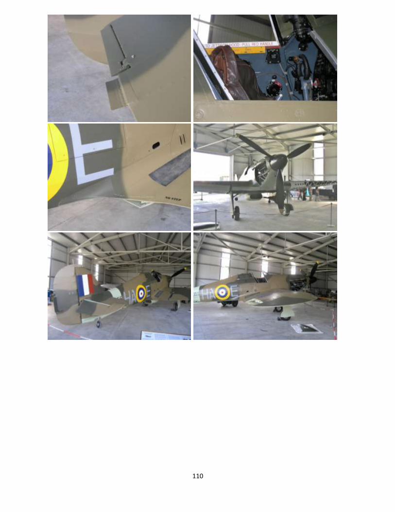
Walk Around Photos by Permission of RCScaleBuilder.com

100

101

102

103

104
105

106
107

108

109
110
111