Construction Documentation Sub-Slab Depressurization ... · 7961 construction documentation:...
58
7961 CONSTRUCTION DOCUMENTATION: SUB-SLAB DEPRESSURIZATION SYSTEM SECOND-PHASE EXPANSION - BUILDING C, LOCKHEED MARTIN MIDDLE RIVER COMPLEX Construction Documentation Sub-Slab Depressurization System Second-Phase Expansion – Building C Lockheed Martin Middle River Complex 2323 Eastern Boulevard Middle River, Maryland Prepared for: Lockheed Martin Corporation Prepared by: Tetra Tech, Inc. September 2013 Michael Martin, P.G. Regional Manager Peter A. Rich, P.E. Project Manager/Principal Engineer
Transcript of Construction Documentation Sub-Slab Depressurization ... · 7961 construction documentation:...

7961 CONSTRUCTION DOCUMENTATION: SUB-SLAB DEPRESSURIZATION SYSTEMSECOND-PHASE EXPANSION - BUILDING C, LOCKHEED MARTIN MIDDLE RIVER COMPLEX
Construction DocumentationSub-Slab Depressurization System
Second-Phase Expansion – Building CLockheed Martin Middle River Complex
2323 Eastern BoulevardMiddle River, Maryland
Prepared for:
Lockheed Martin Corporation
Prepared by:
Tetra Tech, Inc.
September 2013
Michael Martin, P.G.Regional Manager
Peter A. Rich, P.E.Project Manager/Principal Engineer
51 Franklin Street, Suite 400
Annapolis, Maryland 21401
7961 Sub-Slab Depressurization System Second-Phase Expansion—Building C, Middle River Complex, Middle River, Maryland Page 1 of 7
September 06, 2013
Mr. Tom BlackmanLockheed Martin Corporation6801 Rockledge Drive —MP CCT 246Bethesda, Maryland 20817
Subject: Construction documentation:Sub-Slab Depressurization System Second-Phase Expansion—Building CMiddle River Complex, Middle River, Maryland
Dear Mr. Blackman:
Tetra Tech, Inc. (Tetra Tech) has completed the second-phase expansion of the sub-slab
depressurization system (SSDS) operating in Building C of the Middle River Complex in Middle
River, Maryland. This letter summarizes the work performed. The second-phase expansion was
completed in accordance with the approved Sub-Slab Depressurization System Expansion, 100%
Design—Building C report, dated March 25, 2013. The SSDS was expanded to address an
additional area in the middle of the Building C basement with elevated levels of volatile organic
compounds (VOCs), and to continue to address the southern basement target area. The objective
is to maintain a negative pressure of 0.01-inches water column in the sub-slab target area to
prevent potential vapor migration to indoor air.
The expansion activities involved the following tasks:
Review and approval of proposed extraction-point locations during the kickoff meetingon December 04, 2012 and the follow-up meeting on January 30, 2013 with the facilitytenant, MRA Systems, Inc., dba Middle River Aircraft Systems (MRAS)
Geophysical utility clearance of proposed extraction points on January 16 , 2013
Subcontractor and equipment mobilization on April 08, 2013
Removal of the original system blower-skid on April 18, 2013
Installation of five vertical extraction points designated SV-30-C, SV-31-C, SV-32-C,SV-33-C, and SV-34-C, completed on April 19, 2013

51 Franklin Street, Suite 400
Annapolis, Maryland 21401
7961 Sub-Slab Depressurization System Second-Phase Expansion—Building C, Middle River Complex, Middle River, Maryland Page 2 of 7
Installation of overhead polyvinyl chloride (PVC) lines to connect the new extractionwells and the original extraction wells (SV-21-C and SV-23-C) to the system, completedon April 19, 2013
Installation of system-effluent overhead pipe and mist-eliminator pad, and completion ofsystem discharge-stack piping modifications, completed on April 23, 2013
Installation of replacement blower skid with heat exchanger and associated appurtenanceson April 23, 2013
Installation of post-heat-exchanger moisture separator on April 24, 2013
Relocation and connection of the vapor-treatment units to the system, completed on April24, 2013
Pre-startup inspection and testing of equipment and piping on April 29, 2013
Installation of two-inch-diameter steel bollards at three new well locations (SV-30-C,SV-31-C, and SV-32-C) on April 25, 2013
Installation of two-inch-diameter steel bollards around the system on April 30, 2013
Construction of frame for blower-skid soundproof enclosure on April 30, 2013
Subcontractor demobilization on April 30, 2013
System startup testing and balancing on May 01, 2013
Collection of air samples from all new extraction wells (including SV-26-C, SV-27-C,SV-28-C, and SV-29-C, which were installed during the first-phase expansion) on May02, 2013
Installation of blower-skid soundproof enclosure, completed on May 08, 2013
Pre-startup full-day system-test run on May 10, 2013
Operational readiness review conference call with Lockheed Martin Corporation andCDM Smith on May 14, 2013
Installation of additional foam board in the interior of the soundproof enclosure on May16, 2013
Startup of expanded system on May 16, 2013
Shipment of the drum of waste generated during the expansion to off-site disposal onMay 17, 2013
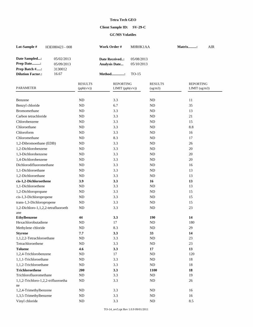
The air samples were collected from each monitoring point a few hours after the SSDS restart
during start-up testing on May 02, 2013. Air samples were collected directly from each
extraction well’s sampling port using one-liter Summa® canisters. Samples were shipped to

51 Franklin Street, Suite 400
Annapolis, Maryland 21401
7961 Sub-Slab Depressurization System Second-Phase Expansion—Building C, Middle River Complex, Middle River, Maryland Page 3 of 7
TestAmerica in Knoxville, Tennessee for VOC analysis by United States Environmental
Protection Agency (USEPA) Method TO-15; results are summarized as follows:
Summary of Analytical Detections (µ/m3)in Extraction Well Samples
May 02, 2013Sub-Slab Depressurization System Second-Phase Expansion
Building C, Middle River Complex, Middle River, Maryland
Constituent Extraction well
SV-26-C SV-27-C SV-28-C SV-29-C SV-30-C SV-31-C SV-32-C SV-33-C SV-34-C
cis-1,2-Dichloro-ethene
42 ND 63 16 140 10 ND 2400 ND
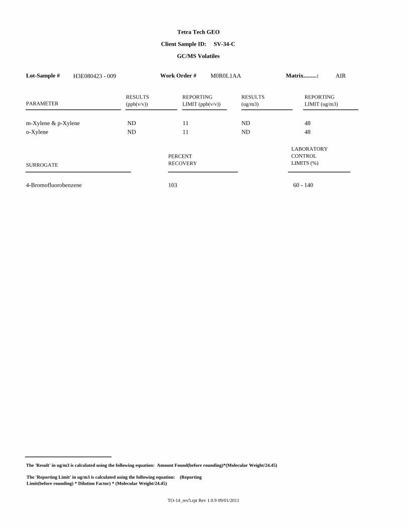
Ethyl-benzene ND ND 71 190 ND ND ND ND ND
Tetrachloroethene ND ND ND ND ND 140 ND ND
Toluene 9.9 10 14 17 ND 9.3 ND ND ND
Trichloroethene 290 400 1400 1100 480 150 4000 89000 260
1,1,2-Trichloro-1,2,2-trifluoroethane
ND 120 ND ND ND ND 440 ND ND
Styrene ND ND ND 33 ND ND ND ND ND
m-xylene andp-xylene
ND ND 410 970 ND ND ND ND ND
o-xylene ND ND 190 450 ND ND ND ND ND
All concentrations are in micrograms per cubic meter (µ/m3).ND—not detected

51 Franklin Street, Suite 400
Annapolis, Maryland 21401
7961 Sub-Slab Depressurization System Second-Phase Expansion—Building C, Middle River Complex, Middle River, Maryland Page 4 of 7
System samples (influent, mid-GAC, and effluent) were collected on May 10, 2013,
approximately one week after the air samples from the extraction point samples were taken. The
system samples were also collected using one-liter Summa® canisters and were shipped to
TestAmerica in Knoxville, Tennessee for VOC analysis by USEPA Method TO-15. The
analytical results are summarized in the following table. Total VOCs in the system influent
increased from 117 µ/m3 on April 08, 2013 to 3,020 µ/m3 on May 10, 2013 after startup of the
expanded system with the new extraction points.
Summary of Analytical Detections (µ/m3)in Sub-Slab Depressurization System Samples
May 10, 2013Building C, Middle River Complex, Middle River, Maryland
Sample Influent Mid-GAC Effluent
Benzene ND ND 9.9
cis-1,2-Dichloroethene 120 ND ND
Trichloroethene 2900 87 34
Total VOCs 3020 87 44
All concentrations are in micrograms per cubic meter air (µ/m3).GAC— granular activated-carbonND— not detectedVOCs—volatile organic compounds
Additional details for the system expansion tasks are in Table 1 (in Attachment 2). The removed
blower/equipment skid was transported to Tetra Tech’s storage space at Martin State Airport for
temporary storage, where it will remain until it is moved to its final destination at another
Lockheed Martin Corporation (Lockheed Martin) project site. The wastes generated from the
expansion consisted of approximately one-third drum of soil and concrete cores from the
installation of the extraction points. This drum was transported on May 17, 2013 for proper off-
site disposal by Clean Harbors of Baltimore, Maryland, using the same waste profile as had been
used for the drum of waste soil generated during the first-phase system expansion.

51 Franklin Street, Suite 400
Annapolis, Maryland 21401
7961 Sub-Slab Depressurization System Second-Phase Expansion—Building C, Middle River Complex, Middle River, Maryland Page 5 of 7
Minor changes from the design documents were made in the field during the construction, as
follows:
The proposed locations for extraction wells SV-30-C, SV-33-C, and SV-31-C were offsetbecause a second layer of concrete was encountered at each location during coring.
The post-heat-exchanger moisture separator (MS-2) was anchored on 4×4-inch woodenposts to match skid height.
A soundproof enclosure was constructed around the entire perimeter of the skidcontaining the blower with heat exchanger, rather than constructing a soundproofenclosure for the blower only; this enclosure will insulate the sound from both the blowerand heat exchanger, and allow for operator access to the system switches.
During the pre-startup system inspection and testing, leaks were observed at some flex-hose
connections, both moisture-separator flanges and the heat-exchanger-effluent pipe. Band clamps
at the flex-hose connections were replaced with tighter clamps and bolts on the moisture-
separator flanges were tightened. Leaks in the slab floor at SV-21-C, SV-23-C, and SV-34-C
were detected using dry ice on May 02, 2013. These leaks, and a leak found in the seal of vapor
monitoring point SV-60-C, were repaired with a pre-mixed concrete floor patch. All piping,
sumps, and valves were labeled.
Tetra Tech provided on-site inspections during construction to ensure that the work complied
with the design documents. Lockheed Martin’s managing contractor (CDM Smith) also
conducted oversight and independent inspections of the work on April 25, 2013 and May 01,
2013. Following fieldwork, the latest version of the SSDS operation and maintenance (O&M)
manual was updated to include the new extraction points, the new blower skid with heat
exchanger, the post-heat-exchanger moisture separator, and associated equipment manufacturer
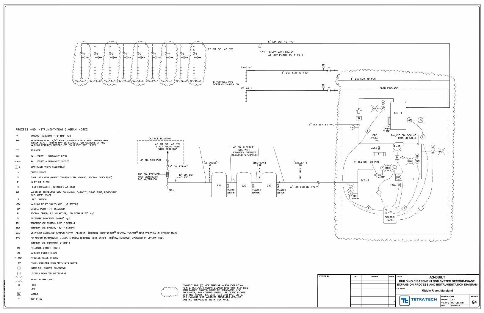
manuals and O&M procedures. As-built drawings, extraction-point construction logs, laboratory
results for air samples, and the updated SSDS operation and maintenance manual are included as
Attachments 3, 4, 5, and 7, respectively.
A high-water alarm in the pre-blower moisture separator (MS-1) occurred on May 16, 2013
following system startup, resulting in system shutdown on May 18, 2013. The system was

51 Franklin Street, Suite 400
Annapolis, Maryland 21401
7961 Sub-Slab Depressurization System Second-Phase Expansion—Building C, Middle River Complex, Middle River, Maryland Page 6 of 7
restarted on May 20, 2013 after removing approximately 50 gallons of condensate from moisture
separator MS-1 and the pipe sumps (on the vacuum side). Extraction well SV-30 was temporarily
closed on May 20, 2013, as it appeared to be the main condensate producer. Similar volumes of
condensate were drained from the vacuum side of the system on May 23, 2013 (48 gallons) and
May 28, 2013 (31 gallons). Subsequently, less than two gallons of condensate were drained on
May 31, 2013, and, to date, no additional condensate requiring draining has accumulated.
To date, adequate induced-vacuum influence is being seen in most of the target zone; exceptions
are vapor monitoring points 133-C, 141-C, and 126-C. Further monitoring and extraction
adjustments will be made to improve vacuum influence. Figure 1 (in Attachment 1) shows the
vacuum influence observed on May 20, 2013, following startup of the expanded system.
If you have any questions regarding the Building C SSDS second-phase expansion, please
contact me at (410) 990-4607 or via email at [email protected].
Sincerely,
Peter A. Rich, P.E.
Project Manager/Principal Engineer
Tetra Tech, Inc.

51 Franklin Street, Suite 400
Annapolis, Maryland 21401
7961 Sub-Slab Depressurization System Second-Phase Expansion—Building C, Middle River Complex, Middle River, Maryland Page 7 of 7
Attachments:
(1) Figure 1—Vacuum Influence, May 20, 2013
(2) Table 1—Summary of Construction Activities
(3) “As-Built Drawings”
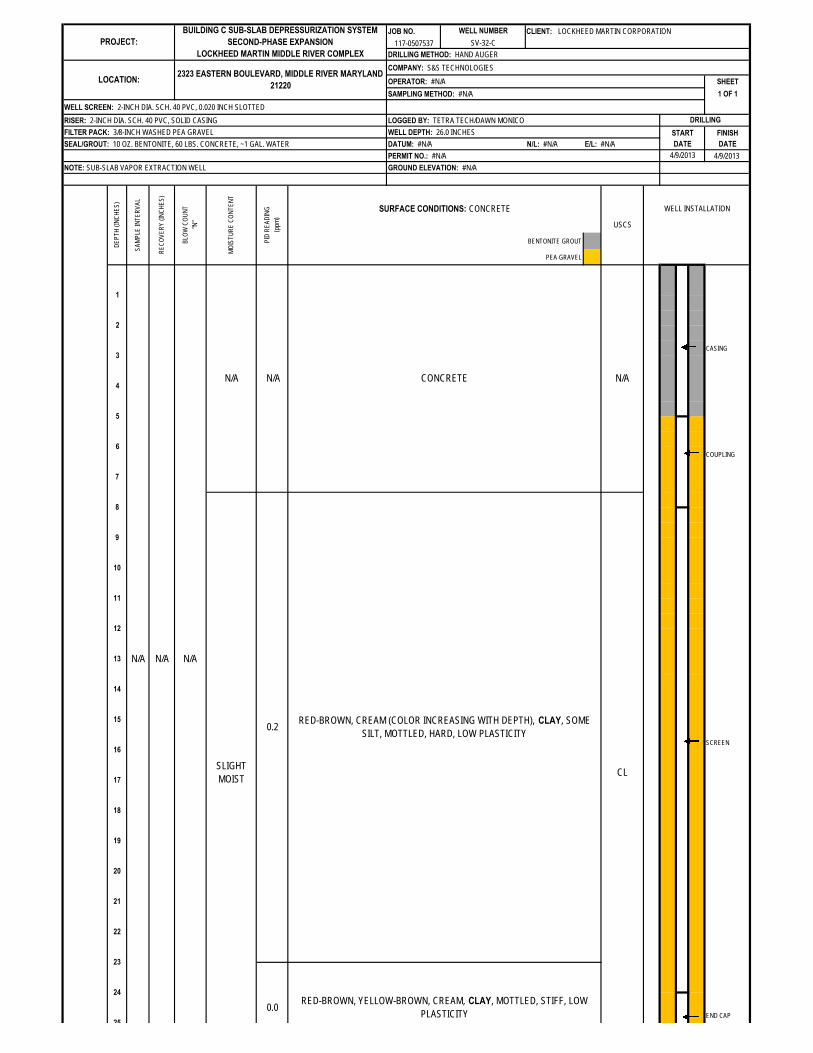
(4) SV-30-C, SV-31-C, SV-32-C, SV-33-C, and SV-34-C Construction Logs
(5) TestAmerica Analytical Report—Extraction-Well Air Sampling
(6) “Waste Disposal Documentation”
(7) Updated Building C Sub-Slab Depressurization System Operation and MaintenanceManual

ATTACHMENT 1
FIGURE 1—VACUUM INFLUENCE
May 20, 2013


ATTACHMENT 2
TABLE 1—SUMMARY OF CONSTRUCTION ACTIVITIES

TABLE 1Summary of Construction Activities
Second-Phase Expansion of the Building C Sub-Slab Depressurization SystemMiddle River Complex, Middle River, Maryland
Date Building C Sub-Slab Depressurization System Expansion Activity
08 April 2013 Mobilized equipment to site.09 April 2013 Concrete-cored for installation of extraction wells SV-30-C, SV-31-C and SV-32-C
and partially cored SV-33-C. Stopped coring due to problems with core drill. Hand-augered soil boring for SV-32-C to a depth of 26 inches below grade surface
(bgs).10 April 2013 Received delivery of spare potassium permanganate zeolite unit from Siemens
Industry, Inc. Hand-augered soil boring for SV-30-C; encountered second layer of concrete at 16
inches bgs. Concrete-cored offset location for SV-30-C. Concrete-cored for SV-34-C and hand-augered soil boring to a depth of 27.5 inches
bgs. Hang-augered soil boring for SV-31-C; encountered second layer of concrete at 8
inches bgs. Need to off-set location.11 April 2013 Concrete-cored offset location for SV-31-C and hand-augered soil boring to a depth
of 15.5 inches bgs. Hand-augered soil boring for SV-30-C; encountered second layer of concrete at 16
inches bgs. Concrete-cored second offset location for SV-30-C and hang-augeredsoil boring to a depth of 24 inches bgs.
Concrete-cored for SV-33-C at planned location and offset location as a secondlayer of concrete was encountered at 8 inches bgs at both locations. Concrete-cored second offset location and hand-augered soil boring to a depth of 27.5 inchesbgs.
Received delivery of 2-inch and 6-inch diameter polyvinyl chloride (PVC) pipe andpipe fittings from Harrington Industrial Plastics.
Received delivery of scissor lift from Volvo Rentals.12 April 2013 Installed extraction wells SV-30-C, SV-31-C, SV-32-C, SV-33-C, and SV-34-C.
Installed valve, sample/measurement port, and 2-inch diameter PVC tie-in pipe forSV-34-C.
15 April 2013 Installed valve, sample/measurement port, and tied-in extraction wells SV-32-C,SV-33-C, and SV-34-C to main 6-inch diameter PVC influent header pipe.
16 April 2013 Installed valve, sample/measurement port, and tied-in extraction wells SV-30-C and
SV-31-C to main header pipe. Began hanging pipe supports for 3-inch diameter PVC pipe to be used to tie original
extraction wells, SV-21-C and SV-23-C, to system at new location.
18 April 2013 Installed 3-inch diameter pipe on ceiling to tie SV-21-C and SV-23-C to main header
pipe. Received delivery of new blower skid from Gasho, Inc. Removed old blower skid and temporarily placed it at column O26. Began installing system effluent 6-inch diameter pipe on building’s south wall.
19 April 2013 Installed valve, sample/measurement port, for SV-21-C and SV-23-C and tied-in to
3-inch diameter manifold pipe. Continued installing system effluent pipe on south wall.
22 April 2013 Moved new blower skid and vapor treatment units into place at column N33. Rerouted main influent header pipe from original skid location to new skid location. Tied-in 3-inch diameter pipe (SV-21-C and SV-23-C manifold) to main header pipe.

TABLE 1Summary of Construction Activities
Second-Phase Expansion of the Building C Sub-Slab Depressurization SystemMiddle River Complex, Middle River, Maryland
Date Building C Sub-Slab Depressurization System Expansion Activity
Installed system effluent pipe at new system location and tied-in to existing 6-inchdiameter effluent header pipe.
23 April 2013 Completed 4-inch and 6-inch diameter system effluent piping on south wall
including installation of mist eliminator pad. Connected 4-inch diameter effluent pipe to existing exhaust stack on the south wall. Connected main influent header pipe to blower skid. Facility (EMCOR) began electrical wiring to provide power for system.
24 April 2013 EMCOR completed electrical wiring for system power. Installed flex hose, fittings, and drains for system’s vapor treatment units. Anchored post-heat exchanger moisture separator (MS-2) on 4x4 inch wood posts. Labeled moisture separators and pipe sumps. Setup level (float) switch for moisture separator MS-2. Setup phone line for autodialer. Received delivery of 2-inch diameter steel bollards. Checked blower rotation direction (changed to necessary clockwise direction).
25 April 2013 CDM Smith inspected system expansion progress. Installed 2-inch diameter bollards around SV-30-C, SV-31-C, and SV-32-C. Installed sample ports at SV-30-C, SV-31-C, SV-32-C, SV-33-C, and SV-34-C. Turned system on briefly to check for leaks at newly installed points and around
system components. Cleaned up around system and removed unused equipment and supplies from site.
Scissor lift picked up by Volvo Rentals.
29 April 2013 Conducted troubleshooting of high pressure alarm (ambient air valve was open) Tested all system alarms. Began completing the Pre-Startup Equipment Inspection Checklist. Programed auto-dialer. Installed drain hose for moisture separator MS-2. Connected high level switch for MS-2 to system’s control panel.
30 April 2013 Installed 2-inch diameter steel bollards (total of 7) around system skid. Transported previous blower skid to Martin State Airport/Hangar 3 (Tetra Tech
storage). Constructed frame for soundproof enclosure with 3-inch diameter galvanized steel
corner posts and 1x6 wood. Replaced loose band clamps on vapor treatment units flex hoses.
01 May 2013 CDM Smith inspected system expansion progress. Drilled holes in dilution and effluent valve handles to install valve lock-out/tag-out
cable. Installed locks on new extraction wells. Labeled main influent 6-inch diameter and 3-inch manifold diameter pipe from
original extraction wells with “vacuum” self-adhesive pipe markers spacedapproximately every 50 feet.
Installed zip ties to camlocks on hoses of vapor treatment units. Installed metal identification tags on system valves. Cut off excess all-thread on blower skid platform. Completed Pre-Startup Equipment Inspection Checklist.

TABLE 1Summary of Construction Activities
Second-Phase Expansion of the Building C Sub-Slab Depressurization SystemMiddle River Complex, Middle River, Maryland
Date Building C Sub-Slab Depressurization System Expansion Activity
Began system startup and testing: Tested new extraction wells for maximum possible flow. Opened SV-21-C, SV-
23-C, SV-26-C, SV-27-C, SV-28-C, SV-29-C, and SV-30-C during testing toprevent system vacuum relief valve from opening due high vacuum.
Leak observed at connection point of steel pipe and heat exchanger effluent. Left system OFF upon departure.
02 May 2013 Leak tested floor slab using dry ice; leaks detected in floor slab at SV-21-C, SV-23-
C, and SV-24-C. Patched holes found during leak test and leak in SV-60-C with concrete patch. Patched previous system vent and effluent penetrations on south wall with foam
sealant/insulation. Turned system ON and conducted a full round of measurements. Adjusted extraction wells to achieve higher flows:
Closed SV-23-C. Possible leak detected at SV-26-C valve (to be checked during next visit).
Collected vapor samples with 1-liter Summa canisters from all new extraction wellsas well as wells installed during the first-phase expansion (SV-26-C through SV-34-C).
Left system OFF upon departure.
07 May 2013 Retested new extraction wells for maximum possible; opened SV-21-C, SV-23-C,
SV-26-C, SV-27-C, SV-28-C, and SV-29-C during testing to prevent systemvacuum relief valve from opening due high vacuum.
Left system OFF upon departure.
08 May 2013 Installed soundproof enclosure around system skid using flexible noise barrier, ½-inch plywood, 2x6-inch wood beams, and 1-inch thick foam board.
09 May 2013 Installed duct work and louver for heat exchanger fan. Set vacuum relief valve to 85 inches of water column.
10 May 2013 Conducted system test run.
14 May 2013 Conducted system Operational Readiness Review via teleconference. Revieweddraft As-Built Drawings and updated operation and maintenance manual. Copies ofthese documents placed on system control panel.
15 May 2013 Began installation of 1-inch thick foam board on interior sides of the soundproofenclosure.
16 May 2013 Completed installation of 1-inch thick foam board on interior sides of the soundproofenclosure.
Started system up for continuous operation.
17 May 2013 Shipped waste soil drum (from extraction well installation) for off-site disposal.
ATTACHMENT 3
AS-BUILT DRAWINGS


ATTACHMENT 4
CONSTRUCTION LOGS
SV-30-C, SV-31-C, SV-32-C, SV-33-C, SV-34-C

JOB NO. CLIENT: LOCKHEED MARTIN CORPORATION
117-0507537
DRILLING METHOD: HAND AUGER
COMPANY: S&S TECHNOLOGIES
OPERATOR: #N/A SHEET
SAMPLING METHOD: #N/A 1 OF 1
WELL SCREEN: 2-INCH DIA. SCH. 40 PVC, 0.020 INCH SLOTTED
RISER: 2-INCH DIA. SCH. 40 PVC, SOLID CASING LOGGED BY: TETRA TECH/DAWN MONICO
FILTER PACK: 3/8-INCH WASHED PEA GRAVEL WELL DEPTH: 24.0 INCHES START FINISH
SEAL/GROUT: 10 OZ. BENTONITE, 60 LBS. CONCRETE, ~1 GAL. WATER DATUM: #N/A N/L: #N/A E/L: #N/A DATE DATE
PERMIT NO.: #N/A 4/11/2013
NOTE: SUB-SLAB VAPOR EXTRACTION WELL GROUND ELEVATION: #N/A
BENTONITE GROUT
PEA GRAVEL
CASING
COUPLING
SCREEN
END CAP
24
N/A
SC
23
CONCRETE
BROWN, CLAYEY SAND, SOME SILT, FINE-GRAINED, COMPACTMOIST 0.0
N/A N/A
15
16
17
END OF BORING = 24.0 INCHES
18
19
20
21
22
12
13
14
7
8
9
10
1
2
3
4
5
6
11
USCS
WELL INSTALLATION
N/A N/A N/A
DRILLING
4/11/2013
DE
PT
H(I
NC
HE
S)
SA
MP
LEIN
TE
RV
AL
RE
CO
VE
RY
(IN
CH
ES
)
BLO
WC
OU
NT
"N"
MO
IST
UR
EC
ON
TE
NT
PID
RE
AD
ING
(ppm
)
SURFACE CONDITIONS: CONCRETE
PROJECT:
BUILDING C SUB-SLAB DEPRESSURIZATION SYSTEM
SECOND-PHASE EXPANSION
LOCKHEED MARTIN MIDDLE RIVER COMPLEX
WELL NUMBER
SV-30-C
LOCATION:2323 EASTERN BOULEVARD, MIDDLE RIVER MARYLAND
21220

JOB NO. CLIENT: LOCKHEED MARTIN CORPORATION
117-0507537
DRILLING METHOD: HAND AUGER
COMPANY: S&S TECHNOLOGIES
OPERATOR: #N/A SHEET
SAMPLING METHOD: #N/A 1 OF 1
WELL SCREEN: 2-INCH DIA. SCH. 40 PVC, 0.020 INCH SLOTTED
RISER: 2-INCH DIA. SCH. 40 PVC, SOLID CASING LOGGED BY: TETRA TECH/DAWN MONICO
FILTER PACK: 3/8-INCH WASHED PEA GRAVEL WELL DEPTH: 15.75 INCHES START FINISH
SEAL/GROUT: 10 OZ. BENTONITE, 60 LBS. CONCRETE, ~1 GAL. WATER DATUM: #N/A N/L: #N/A E/L: #N/A DATE DATE
PERMIT NO.: #N/A 4/11/2013
NOTE: SUB-SLAB VAPOR EXTRACTION WELL GROUND ELEVATION: #N/A
BENTONITE GROUT
PEA GRAVEL
CASING
COUPLING
SCREEN
END CAP
N/A
CL
14
15
END OF BORING = 15.75 INCHES
CONCRETE
RED-BROWN, YELLOW-BROWN, SANDY SILTY CLAY, MOTTLED, SOFT, LOW
PLASTICITY
N/A
MOIST
WET
N/A
0.0
8
9
10
11
12
13
5
6
7
N/A N/A
1
2
3
4
USCS
WELL INSTALLATION
N/A
DRILLING
4/11/2013
DE
PT
H(I
NC
HE
S)
SA
MP
LEIN
TE
RV
AL
RE
CO
VE
RY
(IN
CH
ES
)
BLO
WC
OU
NT
"N"
MO
IST
UR
EC
ON
TE
NT
PID
RE
AD
ING
(ppm
)
SURFACE CONDITIONS: CONCRETE
PROJECT:
BUILDING C SUB-SLAB DEPRESSURIZATION SYSTEM
SECOND-PHASE EXPANSION
LOCKHEED MARTIN MIDDLE RIVER COMPLEX
WELL NUMBER
SV-31-C
LOCATION:2323 EASTERN BOULEVARD, MIDDLE RIVER MARYLAND
21220
JOB NO. CLIENT: LOCKHEED MARTIN CORPORATION
117-0507537
DRILLING METHOD: HAND AUGER
COMPANY: S&S TECHNOLOGIES
OPERATOR: #N/A SHEET
SAMPLING METHOD: #N/A 1 OF 1
WELL SCREEN: 2-INCH DIA. SCH. 40 PVC, 0.020 INCH SLOTTED
RISER: 2-INCH DIA. SCH. 40 PVC, SOLID CASING LOGGED BY: TETRA TECH/DAWN MONICO
FILTER PACK: 3/8-INCH WASHED PEA GRAVEL WELL DEPTH: 26.0 INCHES START FINISH
SEAL/GROUT: 10 OZ. BENTONITE, 60 LBS. CONCRETE, ~1 GAL. WATER DATUM: #N/A N/L: #N/A E/L: #N/A DATE DATE
PERMIT NO.: #N/A 4/9/2013
NOTE: SUB-SLAB VAPOR EXTRACTION WELL GROUND ELEVATION: #N/A
BENTONITE GROUT
PEA GRAVEL
CASING
COUPLING
SCREEN
END CAP
14
SLIGHT
MOIST
RED-BROWN, YELLOW-BROWN, CREAM, CLAY, MOTTLED, STIFF, LOW
PLASTICITY
N/A
CL
CONCRETEN/A
19
RED-BROWN, CREAM (COLOR INCREASING WITH DEPTH), CLAY, SOME
SILT, MOTTLED, HARD, LOW PLASTICITY0.2
0.0
20
21
22
23
24
25
9
10
11
12
13
15
16
17
18
5
6
7
1
2
3
4
8
USCS
WELL INSTALLATION
N/A N/A N/A
N/A
DRILLING
4/9/2013
DE
PT
H(I
NC
HE
S)
SA
MP
LEIN
TE
RV
AL
RE
CO
VE
RY
(IN
CH
ES
)
BLO
WC
OU
NT
"N"
MO
IST
UR
EC
ON
TE
NT
PID
RE
AD
ING
(ppm
)
SURFACE CONDITIONS: CONCRETE
PROJECT:
BUILDING C SUB-SLAB DEPRESSURIZATION SYSTEM
SECOND-PHASE EXPANSION
LOCKHEED MARTIN MIDDLE RIVER COMPLEX
WELL NUMBER
SV-32-C
LOCATION:2323 EASTERN BOULEVARD, MIDDLE RIVER MARYLAND
21220

JOB NO. CLIENT: LOCKHEED MARTIN CORPORATION
117-0507537
DRILLING METHOD: HAND AUGER
COMPANY: S&S TECHNOLOGIES
OPERATOR: #N/A SHEET
SAMPLING METHOD: #N/A 1 OF 1
WELL SCREEN: 2-INCH DIA. SCH. 40 PVC, 0.020 INCH SLOTTED
RISER: 2-INCH DIA. SCH. 40 PVC, SOLID CASING LOGGED BY: TETRA TECH/DAWN MONICO
FILTER PACK: 3/8-INCH WASHED PEA GRAVEL WELL DEPTH: 26.0 INCHES START FINISH
SEAL/GROUT: 10 OZ. BENTONITE, 60 LBS. CONCRETE, ~1 GAL. WATER DATUM: #N/A N/L: #N/A E/L: #N/A DATE DATE
PERMIT NO.: #N/A 4/9/2013
NOTE: SUB-SLAB VAPOR EXTRACTION WELL GROUND ELEVATION: #N/A
BENTONITE GROUT
PEA GRAVEL
USCS
WELL INSTALLATION
DRILLING
4/9/2013
DE
PT
H(I
NC
HE
S)
SA
MP
LEIN
TE
RV
AL
RE
CO
VE
RY
(IN
CH
ES
)
BLO
WC
OU
NT
"N"
MO
IST
UR
EC
ON
TE
NT
PID
RE
AD
ING
(ppm
)
SURFACE CONDITIONS: CONCRETE
PROJECT:
BUILDING C SUB-SLAB DEPRESSURIZATION SYSTEM
SECOND-PHASE EXPANSION
LOCKHEED MARTIN MIDDLE RIVER COMPLEX
WELL NUMBER
SV-32-C
LOCATION:2323 EASTERN BOULEVARD, MIDDLE RIVER MARYLAND
21220
26
25
END OF BORING = 26.0 INCHES

JOB NO. CLIENT: LOCKHEED MARTIN CORPORATION
117-0507537
DRILLING METHOD: HAND AUGER
COMPANY: S&S TECHNOLOGIES
OPERATOR: #N/A SHEET
SAMPLING METHOD: #N/A 1 OF 1
WELL SCREEN: 2-INCH DIA. SCH. 40 PVC, 0.020 INCH SLOTTED
RISER: 2-INCH DIA. SCH. 40 PVC, SOLID CASING LOGGED BY: TETRA TECH/DAWN MONICO
FILTER PACK: 3/8-INCH WASHED PEA GRAVEL WELL DEPTH: 27.0 INCHES START FINISH
SEAL/GROUT: 10 OZ. BENTONITE, 60 LBS. CONCRETE, ~1 GAL. WATER DATUM: #N/A N/L: #N/A E/L: #N/A DATE DATE
PERMIT NO.: #N/A 4/11/2013
NOTE: SUB-SLAB VAPOR EXTRACTION WELL GROUND ELEVATION: #N/A
BENTONITE GROUT
PEA GRAVEL
CASING
COUPLING
SCREEN
CONCRETEN/AN/A N/A
UNKNOWN BLACK MATERIAL
RED-BROWN, LIGHT GRAY, YELLOW-BROWN, CLAY, MOTTLED, HARD, LOW
PLASTICITY
4.0SLIGHT
MOIST
RED-BROWN, CLAY, HARD, LOW PLASTICITY
24
25
CL
18
19
20
21
22
23
12
13
14
15
16
17
9
10
11
1
2
3
4
5
6
USCS
WELL INSTALLATION
N/A N/A N/A
7
8
DRILLING
4/11/2013
DE
PT
H(I
NC
HE
S)
SA
MP
LEIN
TE
RV
AL
RE
CO
VE
RY
(IN
CH
ES
)
BLO
WC
OU
NT
"N"
MO
IST
UR
EC
ON
TE
NT
PID
RE
AD
ING
(ppm
)
SURFACE CONDITIONS: CONCRETE
PROJECT:
BUILDING C SUB-SLAB DEPRESSURIZATION SYSTEM
SECOND-PHASE EXPANSION
LOCKHEED MARTIN MIDDLE RIVER COMPLEX
WELL NUMBER
SV-33-C
LOCATION:2323 EASTERN BOULEVARD, MIDDLE RIVER MARYLAND
21220

JOB NO. CLIENT: LOCKHEED MARTIN CORPORATION
117-0507537
DRILLING METHOD: HAND AUGER
COMPANY: S&S TECHNOLOGIES
OPERATOR: #N/A SHEET
SAMPLING METHOD: #N/A 1 OF 1
WELL SCREEN: 2-INCH DIA. SCH. 40 PVC, 0.020 INCH SLOTTED
RISER: 2-INCH DIA. SCH. 40 PVC, SOLID CASING LOGGED BY: TETRA TECH/DAWN MONICO
FILTER PACK: 3/8-INCH WASHED PEA GRAVEL WELL DEPTH: 27.0 INCHES START FINISH
SEAL/GROUT: 10 OZ. BENTONITE, 60 LBS. CONCRETE, ~1 GAL. WATER DATUM: #N/A N/L: #N/A E/L: #N/A DATE DATE
PERMIT NO.: #N/A 4/11/2013
NOTE: SUB-SLAB VAPOR EXTRACTION WELL GROUND ELEVATION: #N/A
BENTONITE GROUT
PEA GRAVEL
USCS
WELL INSTALLATION
DRILLING
4/11/2013
DE
PT
H(I
NC
HE
S)
SA
MP
LEIN
TE
RV
AL
RE
CO
VE
RY
(IN
CH
ES
)
BLO
WC
OU
NT
"N"
MO
IST
UR
EC
ON
TE
NT
PID
RE
AD
ING
(ppm
)
SURFACE CONDITIONS: CONCRETE
PROJECT:
BUILDING C SUB-SLAB DEPRESSURIZATION SYSTEM
SECOND-PHASE EXPANSION
LOCKHEED MARTIN MIDDLE RIVER COMPLEX
WELL NUMBER
SV-33-C
LOCATION:2323 EASTERN BOULEVARD, MIDDLE RIVER MARYLAND
21220
END CAP
27
RED-BROWN, CLAY, HARD, LOW PLASTICITY25
END OF BORING = 27.0 INCHES
26

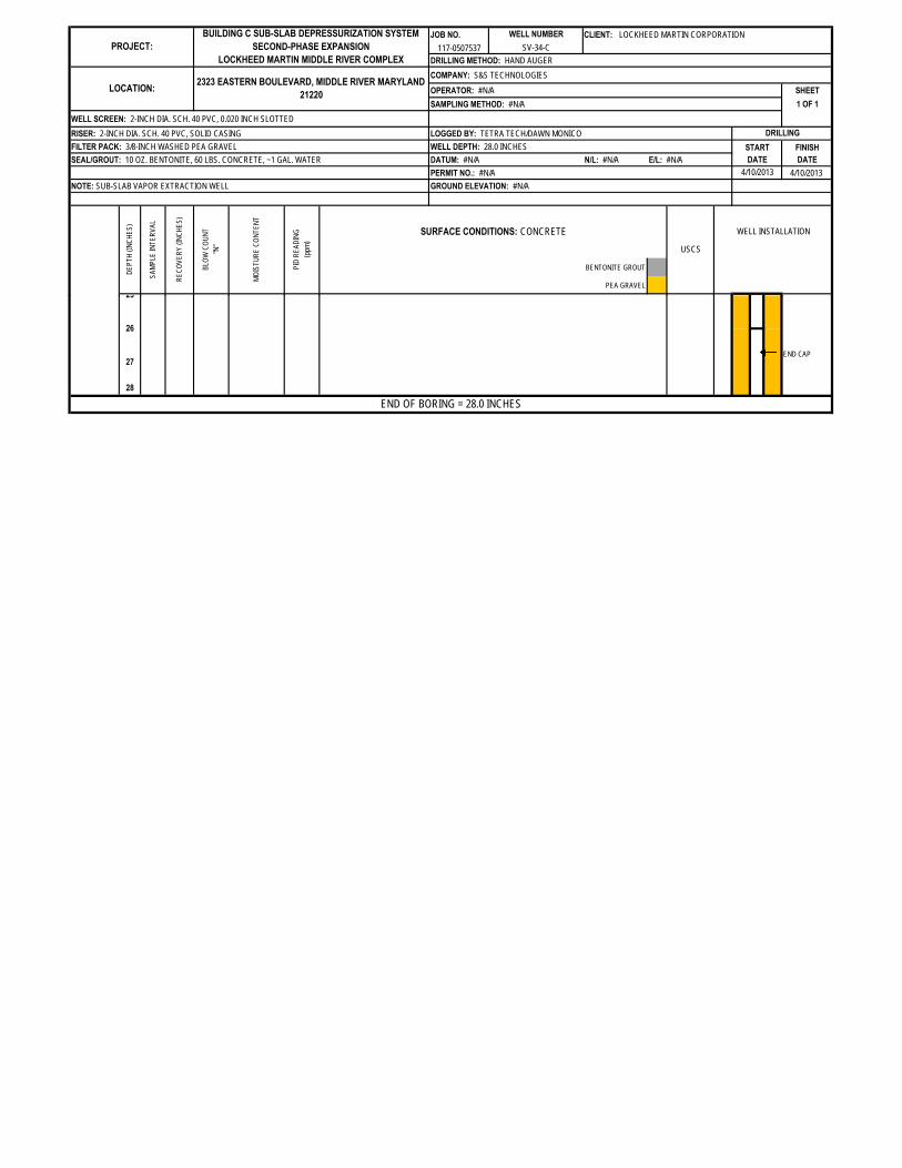
JOB NO. CLIENT: LOCKHEED MARTIN CORPORATION
117-0507537
DRILLING METHOD: HAND AUGER
COMPANY: S&S TECHNOLOGIES
OPERATOR: #N/A SHEET
SAMPLING METHOD: #N/A 1 OF 1
WELL SCREEN: 2-INCH DIA. SCH. 40 PVC, 0.020 INCH SLOTTED
RISER: 2-INCH DIA. SCH. 40 PVC, SOLID CASING LOGGED BY: TETRA TECH/DAWN MONICO
FILTER PACK: 3/8-INCH WASHED PEA GRAVEL WELL DEPTH: 28.0 INCHES START FINISH
SEAL/GROUT: 10 OZ. BENTONITE, 60 LBS. CONCRETE, ~1 GAL. WATER DATUM: #N/A N/L: #N/A E/L: #N/A DATE DATE
PERMIT NO.: #N/A 4/10/2013
NOTE: SUB-SLAB VAPOR EXTRACTION WELL GROUND ELEVATION: #N/A
BENTONITE GROUT
PEA GRAVEL
CASING
COUPLING
SCREEN
RED-BROWN, YELLOW-BROWN, SILTY CLAY, MOTTLED, SOFT, MODERATE
PLASTICITY (BLACK MOTTLES IN TOP 3 INCHES)CL
22
23
24
12
13
14
15
16
17
10
MOIST 0.0
18
19
20
21
25
11
N/A
1
2
3
4
5
6
7
8
9
USCS
WELL INSTALLATION
N/A N/A N/A
N/A N/A CONCRETE
DRILLING
4/10/2013
DE
PT
H(I
NC
HE
S)
SA
MP
LEIN
TE
RV
AL
RE
CO
VE
RY
(IN
CH
ES
)
BLO
WC
OU
NT
"N"
MO
IST
UR
EC
ON
TE
NT
PID
RE
AD
ING
(ppm
)
SURFACE CONDITIONS: CONCRETE
PROJECT:
BUILDING C SUB-SLAB DEPRESSURIZATION SYSTEM
SECOND-PHASE EXPANSION
LOCKHEED MARTIN MIDDLE RIVER COMPLEX
WELL NUMBER
SV-34-C
LOCATION:2323 EASTERN BOULEVARD, MIDDLE RIVER MARYLAND
21220
JOB NO. CLIENT: LOCKHEED MARTIN CORPORATION
117-0507537
DRILLING METHOD: HAND AUGER
COMPANY: S&S TECHNOLOGIES
OPERATOR: #N/A SHEET
SAMPLING METHOD: #N/A 1 OF 1
WELL SCREEN: 2-INCH DIA. SCH. 40 PVC, 0.020 INCH SLOTTED
RISER: 2-INCH DIA. SCH. 40 PVC, SOLID CASING LOGGED BY: TETRA TECH/DAWN MONICO
FILTER PACK: 3/8-INCH WASHED PEA GRAVEL WELL DEPTH: 28.0 INCHES START FINISH
SEAL/GROUT: 10 OZ. BENTONITE, 60 LBS. CONCRETE, ~1 GAL. WATER DATUM: #N/A N/L: #N/A E/L: #N/A DATE DATE
PERMIT NO.: #N/A 4/10/2013
NOTE: SUB-SLAB VAPOR EXTRACTION WELL GROUND ELEVATION: #N/A
BENTONITE GROUT
PEA GRAVEL
USCS
WELL INSTALLATION
DRILLING
4/10/2013
DE
PT
H(I
NC
HE
S)
SA
MP
LEIN
TE
RV
AL
RE
CO
VE
RY
(IN
CH
ES
)
BLO
WC
OU
NT
"N"
MO
IST
UR
EC
ON
TE
NT
PID
RE
AD
ING
(ppm
)
SURFACE CONDITIONS: CONCRETE
PROJECT:
BUILDING C SUB-SLAB DEPRESSURIZATION SYSTEM
SECOND-PHASE EXPANSION
LOCKHEED MARTIN MIDDLE RIVER COMPLEX
WELL NUMBER
SV-34-C
LOCATION:2323 EASTERN BOULEVARD, MIDDLE RIVER MARYLAND
21220
END CAP
28
END OF BORING = 28.0 INCHES
27
25
26
ATTACHMENT 5
TESTAMERICA ANALYTICAL REPORT—
EXTRACTION-WELL AIR SAMPLING

Tetra Tech GEO
Matrix.........: Work Order #Lot-Sample #
GC/MS Volatiles
Client Sample ID: SV-30-C
M0R0C1AA AIRH3E080423 - 001
TO-15Method..............:
05/11/2013Analysis Date...
05/08/2013Date Received..:
124.78Dilution Factor.:
3133018Prep Batch #.....:
05/10/2013Prep Date.........:
05/02/2013Date Sampled...:
PARAMETERRESULTS
(ug/m3)
RESULTS
(ppb(v/v))
REPORTING
LIMIT (ppb(v/v))
REPORTING
LIMIT (ug/m3)
ND 80Benzene ND 25
ND 260Benzyl chloride ND 50
ND 97Bromomethane ND 25
ND 160Carbon tetrachloride ND 25
ND 110Chlorobenzene ND 25
ND 66Chloroethane ND 25
ND 120Chloroform ND 25
ND 130Chloromethane ND 62
ND 1901,2-Dibromoethane (EDB) ND 25
ND 1501,2-Dichlorobenzene ND 25
ND 1501,3-Dichlorobenzene ND 25
ND 1501,4-Dichlorobenzene ND 25
ND 120Dichlorodifluoromethane ND 25
ND 1001,1-Dichloroethane ND 25
ND 1001,2-Dichloroethane ND 25
99140 cis-1,2-Dichloroethene 35 25
ND 991,1-Dichloroethene ND 25
ND 1201,2-Dichloropropane ND 25
ND 110cis-1,3-Dichloropropene ND 25
ND 110trans-1,3-Dichloropropene ND 25
ND 1701,2-Dichloro-1,1,2,2-tetrafluoroeth
ane
ND 25
ND 110Ethylbenzene ND 25
ND 1300Hexachlorobutadiene ND 120
ND 220Methylene chloride ND 62
ND 110Styrene ND 25
ND 1701,1,2,2-Tetrachloroethane ND 25
ND 170Tetrachloroethene ND 25
ND 94Toluene ND 25
ND 9301,2,4-Trichlorobenzene ND 120
ND 1401,1,1-Trichloroethane ND 25
ND 1401,1,2-Trichloroethane ND 25
130480 Trichloroethene 90 25
ND 140Trichlorofluoromethane ND 25
ND 1901,1,2-Trichloro-1,2,2-trifluoroetha
ne
ND 25
ND 1201,2,4-Trimethylbenzene ND 25
ND 1201,3,5-Trimethylbenzene ND 25
ND 64Vinyl chloride ND 25
TO-14_rev5.rpt Rev 1.0.9 09/01/2011

Tetra Tech GEO
Matrix.........: Work Order #Lot-Sample #
GC/MS Volatiles
Client Sample ID: SV-30-C
M0R0C1AA AIRH3E080423 - 001
PARAMETERRESULTS
(ug/m3)
RESULTS
(ppb(v/v))
REPORTING
LIMIT (ppb(v/v))
REPORTING
LIMIT (ug/m3)
ND 110m-Xylene & p-Xylene ND 25
ND 110o-Xylene ND 25
LABORATORY
CONTROL
LIMITS (%)
PERCENT
RECOVERYSURROGATE
60 - 1404-Bromofluorobenzene 102
The 'Result' in ug/m3 is calculated using the following equation: Amount Found(before rounding)*(Molecular Weight/24.45)
The 'Reporting Limit' in ug/m3 is calculated using the following equation: (Reporting
Limit(before rounding) * Dilution Factor) * (Molecular Weight/24.45)
TO-14_rev5.rpt Rev 1.0.9 09/01/2011

Tetra Tech GEO
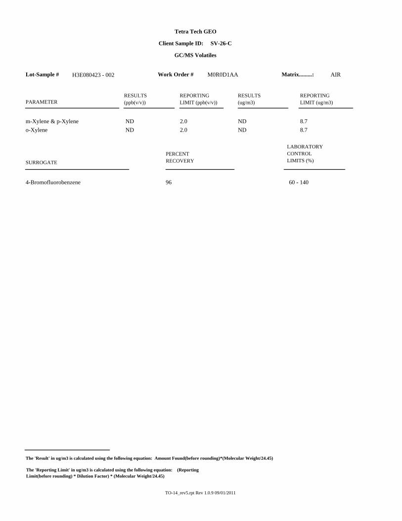
Matrix.........: Work Order #Lot-Sample #
GC/MS Volatiles
Client Sample ID: SV-26-C
M0R0D1AA AIRH3E080423 - 002
TO-15Method..............:
05/10/2013Analysis Date...
05/08/2013Date Received..:
10Dilution Factor.:
3130012Prep Batch #.....:
05/09/2013Prep Date.........:
05/02/2013Date Sampled...:
PARAMETERRESULTS
(ug/m3)
RESULTS
(ppb(v/v))
REPORTING
LIMIT (ppb(v/v))
REPORTING
LIMIT (ug/m3)
ND 6.4Benzene ND 2.0
ND 21Benzyl chloride ND 4.0
ND 7.8Bromomethane ND 2.0
ND 13Carbon tetrachloride ND 2.0
ND 9.2Chlorobenzene ND 2.0
ND 5.3Chloroethane ND 2.0
ND 9.8Chloroform ND 2.0
ND 10Chloromethane ND 5.0
ND 151,2-Dibromoethane (EDB) ND 2.0
ND 121,2-Dichlorobenzene ND 2.0
ND 121,3-Dichlorobenzene ND 2.0
ND 121,4-Dichlorobenzene ND 2.0
ND 9.9Dichlorodifluoromethane ND 2.0
ND 8.11,1-Dichloroethane ND 2.0
ND 8.11,2-Dichloroethane ND 2.0
7.942 cis-1,2-Dichloroethene 11 2.0
ND 7.91,1-Dichloroethene ND 2.0
ND 9.21,2-Dichloropropane ND 2.0
ND 9.1cis-1,3-Dichloropropene ND 2.0
ND 9.1trans-1,3-Dichloropropene ND 2.0
ND 141,2-Dichloro-1,1,2,2-tetrafluoroeth
ane
ND 2.0
ND 8.7Ethylbenzene ND 2.0
ND 110Hexachlorobutadiene ND 10
ND 17Methylene chloride ND 5.0
ND 8.5Styrene ND 2.0
ND 141,1,2,2-Tetrachloroethane ND 2.0
ND 14Tetrachloroethene ND 2.0
7.59.9 Toluene 2.6 2.0
ND 741,2,4-Trichlorobenzene ND 10
ND 111,1,1-Trichloroethane ND 2.0
ND 111,1,2-Trichloroethane ND 2.0
11290 Trichloroethene 54 2.0
ND 11Trichlorofluoromethane ND 2.0
ND 151,1,2-Trichloro-1,2,2-trifluoroetha
ne
ND 2.0
ND 9.81,2,4-Trimethylbenzene ND 2.0
ND 9.81,3,5-Trimethylbenzene ND 2.0
ND 5.1Vinyl chloride ND 2.0
TO-14_rev5.rpt Rev 1.0.9 09/01/2011
Tetra Tech GEO
Matrix.........: Work Order #Lot-Sample #
GC/MS Volatiles
Client Sample ID: SV-26-C
M0R0D1AA AIRH3E080423 - 002
PARAMETERRESULTS
(ug/m3)
RESULTS
(ppb(v/v))
REPORTING
LIMIT (ppb(v/v))
REPORTING
LIMIT (ug/m3)
ND 8.7m-Xylene & p-Xylene ND 2.0
ND 8.7o-Xylene ND 2.0
LABORATORY
CONTROL
LIMITS (%)
PERCENT
RECOVERYSURROGATE
60 - 1404-Bromofluorobenzene 96
The 'Result' in ug/m3 is calculated using the following equation: Amount Found(before rounding)*(Molecular Weight/24.45)
The 'Reporting Limit' in ug/m3 is calculated using the following equation: (Reporting
Limit(before rounding) * Dilution Factor) * (Molecular Weight/24.45)
TO-14_rev5.rpt Rev 1.0.9 09/01/2011

Tetra Tech GEO
Matrix.........: Work Order #Lot-Sample #
GC/MS Volatiles
Client Sample ID: SV-31-C
M0R0E1AA AIRH3E080423 - 003
TO-15Method..............:
05/10/2013Analysis Date...
05/08/2013Date Received..:
10Dilution Factor.:
3130012Prep Batch #.....:
05/09/2013Prep Date.........:
05/02/2013Date Sampled...:
PARAMETERRESULTS
(ug/m3)
RESULTS
(ppb(v/v))
REPORTING
LIMIT (ppb(v/v))
REPORTING
LIMIT (ug/m3)
ND 6.4Benzene ND 2.0
ND 21Benzyl chloride ND 4.0
ND 7.8Bromomethane ND 2.0
ND 13Carbon tetrachloride ND 2.0
ND 9.2Chlorobenzene ND 2.0
ND 5.3Chloroethane ND 2.0
ND 9.8Chloroform ND 2.0
ND 10Chloromethane ND 5.0
ND 151,2-Dibromoethane (EDB) ND 2.0
ND 121,2-Dichlorobenzene ND 2.0
ND 121,3-Dichlorobenzene ND 2.0
ND 121,4-Dichlorobenzene ND 2.0
ND 9.9Dichlorodifluoromethane ND 2.0
ND 8.11,1-Dichloroethane ND 2.0
ND 8.11,2-Dichloroethane ND 2.0
7.910.0 cis-1,2-Dichloroethene 2.5 2.0
ND 7.91,1-Dichloroethene ND 2.0
ND 9.21,2-Dichloropropane ND 2.0
ND 9.1cis-1,3-Dichloropropene ND 2.0
ND 9.1trans-1,3-Dichloropropene ND 2.0
ND 141,2-Dichloro-1,1,2,2-tetrafluoroeth
ane
ND 2.0
ND 8.7Ethylbenzene ND 2.0
ND 110Hexachlorobutadiene ND 10
ND 17Methylene chloride ND 5.0
ND 8.5Styrene ND 2.0
ND 141,1,2,2-Tetrachloroethane ND 2.0
ND 14Tetrachloroethene ND 2.0
7.59.3 Toluene 2.5 2.0
ND 741,2,4-Trichlorobenzene ND 10
ND 111,1,1-Trichloroethane ND 2.0
ND 111,1,2-Trichloroethane ND 2.0
11150 Trichloroethene 29 2.0
ND 11Trichlorofluoromethane ND 2.0
ND 151,1,2-Trichloro-1,2,2-trifluoroetha
ne
ND 2.0
ND 9.81,2,4-Trimethylbenzene ND 2.0
ND 9.81,3,5-Trimethylbenzene ND 2.0
ND 5.1Vinyl chloride ND 2.0
TO-14_rev5.rpt Rev 1.0.9 09/01/2011

Tetra Tech GEO
Matrix.........: Work Order #Lot-Sample #
GC/MS Volatiles
Client Sample ID: SV-31-C
M0R0E1AA AIRH3E080423 - 003
PARAMETERRESULTS
(ug/m3)
RESULTS
(ppb(v/v))
REPORTING
LIMIT (ppb(v/v))
REPORTING
LIMIT (ug/m3)
ND 8.7m-Xylene & p-Xylene ND 2.0
ND 8.7o-Xylene ND 2.0
LABORATORY
CONTROL
LIMITS (%)
PERCENT
RECOVERYSURROGATE
60 - 1404-Bromofluorobenzene 97
The 'Result' in ug/m3 is calculated using the following equation: Amount Found(before rounding)*(Molecular Weight/24.45)
The 'Reporting Limit' in ug/m3 is calculated using the following equation: (Reporting
Limit(before rounding) * Dilution Factor) * (Molecular Weight/24.45)
TO-14_rev5.rpt Rev 1.0.9 09/01/2011

Tetra Tech GEO
Matrix.........: Work Order #Lot-Sample #
GC/MS Volatiles
Client Sample ID: SV-27-C
M0R0F1AA AIRH3E080423 - 004
TO-15Method..............:
05/10/2013Analysis Date...
05/08/2013Date Received..:
10Dilution Factor.:
3130012Prep Batch #.....:
05/09/2013Prep Date.........:
05/02/2013Date Sampled...:
PARAMETERRESULTS
(ug/m3)
RESULTS
(ppb(v/v))
REPORTING
LIMIT (ppb(v/v))
REPORTING
LIMIT (ug/m3)
ND 6.4Benzene ND 2.0
ND 21Benzyl chloride ND 4.0
ND 7.8Bromomethane ND 2.0
ND 13Carbon tetrachloride ND 2.0
ND 9.2Chlorobenzene ND 2.0
ND 5.3Chloroethane ND 2.0
ND 9.8Chloroform ND 2.0
ND 10Chloromethane ND 5.0
ND 151,2-Dibromoethane (EDB) ND 2.0
ND 121,2-Dichlorobenzene ND 2.0
ND 121,3-Dichlorobenzene ND 2.0
ND 121,4-Dichlorobenzene ND 2.0
ND 9.9Dichlorodifluoromethane ND 2.0
ND 8.11,1-Dichloroethane ND 2.0
ND 8.11,2-Dichloroethane ND 2.0
ND 7.9cis-1,2-Dichloroethene ND 2.0
ND 7.91,1-Dichloroethene ND 2.0
ND 9.21,2-Dichloropropane ND 2.0
ND 9.1cis-1,3-Dichloropropene ND 2.0
ND 9.1trans-1,3-Dichloropropene ND 2.0
ND 141,2-Dichloro-1,1,2,2-tetrafluoroeth
ane
ND 2.0
ND 8.7Ethylbenzene ND 2.0
ND 110Hexachlorobutadiene ND 10
ND 17Methylene chloride ND 5.0
ND 8.5Styrene ND 2.0
ND 141,1,2,2-Tetrachloroethane ND 2.0
ND 14Tetrachloroethene ND 2.0
7.510 Toluene 2.7 2.0
ND 741,2,4-Trichlorobenzene ND 10
ND 111,1,1-Trichloroethane ND 2.0
ND 111,1,2-Trichloroethane ND 2.0
11400 Trichloroethene 75 2.0
ND 11Trichlorofluoromethane ND 2.0
15120 1,1,2-Trichloro-1,2,2-trifluoroet
hane
16 2.0
ND 9.81,2,4-Trimethylbenzene ND 2.0
ND 9.81,3,5-Trimethylbenzene ND 2.0
ND 5.1Vinyl chloride ND 2.0
TO-14_rev5.rpt Rev 1.0.9 09/01/2011

Tetra Tech GEO
Matrix.........: Work Order #Lot-Sample #
GC/MS Volatiles
Client Sample ID: SV-27-C
M0R0F1AA AIRH3E080423 - 004
PARAMETERRESULTS
(ug/m3)
RESULTS
(ppb(v/v))
REPORTING
LIMIT (ppb(v/v))
REPORTING
LIMIT (ug/m3)
ND 8.7m-Xylene & p-Xylene ND 2.0
ND 8.7o-Xylene ND 2.0
LABORATORY
CONTROL
LIMITS (%)
PERCENT
RECOVERYSURROGATE
60 - 1404-Bromofluorobenzene 98
The 'Result' in ug/m3 is calculated using the following equation: Amount Found(before rounding)*(Molecular Weight/24.45)
The 'Reporting Limit' in ug/m3 is calculated using the following equation: (Reporting
Limit(before rounding) * Dilution Factor) * (Molecular Weight/24.45)
TO-14_rev5.rpt Rev 1.0.9 09/01/2011

Tetra Tech GEO
Matrix.........: Work Order #Lot-Sample #
GC/MS Volatiles
Client Sample ID: SV-32-C
M0R0G1AA AIRH3E080423 - 005
TO-15Method..............:
05/10/2013Analysis Date...
05/08/2013Date Received..:
66.91Dilution Factor.:
3130012Prep Batch #.....:
05/09/2013Prep Date.........:
05/02/2013Date Sampled...:
PARAMETERRESULTS
(ug/m3)
RESULTS
(ppb(v/v))
REPORTING
LIMIT (ppb(v/v))
REPORTING
LIMIT (ug/m3)
ND 43Benzene ND 13
ND 140Benzyl chloride ND 27
ND 52Bromomethane ND 13
ND 84Carbon tetrachloride ND 13
ND 62Chlorobenzene ND 13
ND 35Chloroethane ND 13
ND 65Chloroform ND 13
ND 69Chloromethane ND 33
ND 1001,2-Dibromoethane (EDB) ND 13
ND 801,2-Dichlorobenzene ND 13
ND 801,3-Dichlorobenzene ND 13
ND 801,4-Dichlorobenzene ND 13
ND 66Dichlorodifluoromethane ND 13
ND 541,1-Dichloroethane ND 13
ND 541,2-Dichloroethane ND 13
ND 53cis-1,2-Dichloroethene ND 13
ND 531,1-Dichloroethene ND 13
ND 621,2-Dichloropropane ND 13
ND 61cis-1,3-Dichloropropene ND 13
ND 61trans-1,3-Dichloropropene ND 13
ND 941,2-Dichloro-1,1,2,2-tetrafluoroeth
ane
ND 13
ND 58Ethylbenzene ND 13
ND 710Hexachlorobutadiene ND 67
ND 120Methylene chloride ND 33
ND 57Styrene ND 13
ND 921,1,2,2-Tetrachloroethane ND 13
91140 Tetrachloroethene 21 13
ND 50Toluene ND 13
ND 5001,2,4-Trichlorobenzene ND 67
ND 731,1,1-Trichloroethane ND 13
ND 731,1,2-Trichloroethane ND 13
724000 Trichloroethene 740 13
ND 75Trichlorofluoromethane ND 13
100440 1,1,2-Trichloro-1,2,2-trifluoroet
hane
57 13
ND 661,2,4-Trimethylbenzene ND 13
ND 661,3,5-Trimethylbenzene ND 13
ND 34Vinyl chloride ND 13
TO-14_rev5.rpt Rev 1.0.9 09/01/2011

Tetra Tech GEO
Matrix.........: Work Order #Lot-Sample #
GC/MS Volatiles
Client Sample ID: SV-32-C
M0R0G1AA AIRH3E080423 - 005
PARAMETERRESULTS
(ug/m3)
RESULTS
(ppb(v/v))
REPORTING
LIMIT (ppb(v/v))
REPORTING
LIMIT (ug/m3)
ND 58m-Xylene & p-Xylene ND 13
ND 58o-Xylene ND 13
LABORATORY
CONTROL
LIMITS (%)
PERCENT
RECOVERYSURROGATE
60 - 1404-Bromofluorobenzene 96
The 'Result' in ug/m3 is calculated using the following equation: Amount Found(before rounding)*(Molecular Weight/24.45)
The 'Reporting Limit' in ug/m3 is calculated using the following equation: (Reporting
Limit(before rounding) * Dilution Factor) * (Molecular Weight/24.45)
TO-14_rev5.rpt Rev 1.0.9 09/01/2011

Tetra Tech GEO
Matrix.........: Work Order #Lot-Sample #
GC/MS Volatiles
Client Sample ID: SV-28-C
M0R0H1AA AIRH3E080423 - 006
TO-15Method..............:
05/10/2013Analysis Date...
05/08/2013Date Received..:
16.67Dilution Factor.:
3130012Prep Batch #.....:
05/09/2013Prep Date.........:
05/02/2013Date Sampled...:
PARAMETERRESULTS
(ug/m3)
RESULTS
(ppb(v/v))
REPORTING
LIMIT (ppb(v/v))
REPORTING
LIMIT (ug/m3)
ND 11Benzene ND 3.3
ND 35Benzyl chloride ND 6.7
ND 13Bromomethane ND 3.3
ND 21Carbon tetrachloride ND 3.3
ND 15Chlorobenzene ND 3.3
ND 8.8Chloroethane ND 3.3
ND 16Chloroform ND 3.3
ND 17Chloromethane ND 8.3
ND 261,2-Dibromoethane (EDB) ND 3.3
ND 201,2-Dichlorobenzene ND 3.3
ND 201,3-Dichlorobenzene ND 3.3
ND 201,4-Dichlorobenzene ND 3.3
ND 16Dichlorodifluoromethane ND 3.3
ND 131,1-Dichloroethane ND 3.3
ND 131,2-Dichloroethane ND 3.3
1363 cis-1,2-Dichloroethene 16 3.3
ND 131,1-Dichloroethene ND 3.3
ND 151,2-Dichloropropane ND 3.3
ND 15cis-1,3-Dichloropropene ND 3.3
ND 15trans-1,3-Dichloropropene ND 3.3
ND 231,2-Dichloro-1,1,2,2-tetrafluoroeth
ane
ND 3.3
1471 Ethylbenzene 16 3.3
ND 180Hexachlorobutadiene ND 17
ND 29Methylene chloride ND 8.3
ND 14Styrene ND 3.3
ND 231,1,2,2-Tetrachloroethane ND 3.3
ND 23Tetrachloroethene ND 3.3
1314 Toluene 3.6 3.3
ND 1201,2,4-Trichlorobenzene ND 17
ND 181,1,1-Trichloroethane ND 3.3
ND 181,1,2-Trichloroethane ND 3.3
181400 Trichloroethene 270 3.3
ND 19Trichlorofluoromethane ND 3.3
ND 261,1,2-Trichloro-1,2,2-trifluoroetha
ne
ND 3.3
ND 161,2,4-Trimethylbenzene ND 3.3
ND 161,3,5-Trimethylbenzene ND 3.3
ND 8.5Vinyl chloride ND 3.3
TO-14_rev5.rpt Rev 1.0.9 09/01/2011

Tetra Tech GEO
Matrix.........: Work Order #Lot-Sample #
GC/MS Volatiles
Client Sample ID: SV-28-C
M0R0H1AA AIRH3E080423 - 006
PARAMETERRESULTS
(ug/m3)
RESULTS
(ppb(v/v))
REPORTING
LIMIT (ppb(v/v))
REPORTING
LIMIT (ug/m3)
14410 m-Xylene & p-Xylene 95 3.3
14190 o-Xylene 43 3.3
LABORATORY
CONTROL
LIMITS (%)
PERCENT
RECOVERYSURROGATE
60 - 1404-Bromofluorobenzene 102
The 'Result' in ug/m3 is calculated using the following equation: Amount Found(before rounding)*(Molecular Weight/24.45)
The 'Reporting Limit' in ug/m3 is calculated using the following equation: (Reporting
Limit(before rounding) * Dilution Factor) * (Molecular Weight/24.45)
TO-14_rev5.rpt Rev 1.0.9 09/01/2011
Tetra Tech GEO
Matrix.........: Work Order #Lot-Sample #
GC/MS Volatiles
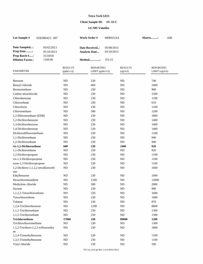
Client Sample ID: SV-33-C
M0R0J1AA AIRH3E080423 - 007
TO-15Method..............:
05/10/2013Analysis Date...
05/08/2013Date Received..:
1160.06Dilution Factor.:
3133018Prep Batch #.....:
05/10/2013Prep Date.........:
05/02/2013Date Sampled...:
PARAMETERRESULTS
(ug/m3)
RESULTS
(ppb(v/v))
REPORTING
LIMIT (ppb(v/v))
REPORTING
LIMIT (ug/m3)
ND 740Benzene ND 230
ND 2400Benzyl chloride ND 460
ND 900Bromomethane ND 230
ND 1500Carbon tetrachloride ND 230
ND 1100Chlorobenzene ND 230
ND 610Chloroethane ND 230
ND 1100Chloroform ND 230
ND 1200Chloromethane ND 580
ND 18001,2-Dibromoethane (EDB) ND 230
ND 14001,2-Dichlorobenzene ND 230
ND 14001,3-Dichlorobenzene ND 230
ND 14001,4-Dichlorobenzene ND 230
ND 1100Dichlorodifluoromethane ND 230
ND 9401,1-Dichloroethane ND 230
ND 9401,2-Dichloroethane ND 230
9202400 cis-1,2-Dichloroethene 600 230
ND 9201,1-Dichloroethene ND 230
ND 11001,2-Dichloropropane ND 230
ND 1100cis-1,3-Dichloropropene ND 230
ND 1100trans-1,3-Dichloropropene ND 230
ND 16001,2-Dichloro-1,1,2,2-tetrafluoroeth
ane
ND 230
ND 1000Ethylbenzene ND 230
ND 12000Hexachlorobutadiene ND 1200
ND 2000Methylene chloride ND 580
ND 990Styrene ND 230
ND 16001,1,2,2-Tetrachloroethane ND 230
ND 1600Tetrachloroethene ND 230
ND 870Toluene ND 230
ND 86001,2,4-Trichlorobenzene ND 1200
ND 13001,1,1-Trichloroethane ND 230
ND 13001,1,2-Trichloroethane ND 230
120089000 Trichloroethene 17000 230
ND 1300Trichlorofluoromethane ND 230
ND 18001,1,2-Trichloro-1,2,2-trifluoroetha
ne
ND 230
ND 11001,2,4-Trimethylbenzene ND 230
ND 11001,3,5-Trimethylbenzene ND 230
ND 590Vinyl chloride ND 230
TO-14_rev5.rpt Rev 1.0.9 09/01/2011

Tetra Tech GEO
Matrix.........: Work Order #Lot-Sample #
GC/MS Volatiles
Client Sample ID: SV-33-C
M0R0J1AA AIRH3E080423 - 007
PARAMETERRESULTS
(ug/m3)
RESULTS
(ppb(v/v))
REPORTING
LIMIT (ppb(v/v))
REPORTING
LIMIT (ug/m3)
ND 1000m-Xylene & p-Xylene ND 230
ND 1000o-Xylene ND 230
LABORATORY
CONTROL
LIMITS (%)
PERCENT
RECOVERYSURROGATE
60 - 1404-Bromofluorobenzene 102
The 'Result' in ug/m3 is calculated using the following equation: Amount Found(before rounding)*(Molecular Weight/24.45)
The 'Reporting Limit' in ug/m3 is calculated using the following equation: (Reporting
Limit(before rounding) * Dilution Factor) * (Molecular Weight/24.45)
TO-14_rev5.rpt Rev 1.0.9 09/01/2011
Tetra Tech GEO
Matrix.........: Work Order #Lot-Sample #
GC/MS Volatiles
Client Sample ID: SV-29-C
M0R0K1AA AIRH3E080423 - 008
TO-15Method..............:
05/10/2013Analysis Date...
05/08/2013Date Received..:
16.67Dilution Factor.:
3130012Prep Batch #.....:
05/09/2013Prep Date.........:
05/02/2013Date Sampled...:
PARAMETERRESULTS
(ug/m3)
RESULTS
(ppb(v/v))
REPORTING
LIMIT (ppb(v/v))
REPORTING
LIMIT (ug/m3)
ND 11Benzene ND 3.3
ND 35Benzyl chloride ND 6.7
ND 13Bromomethane ND 3.3
ND 21Carbon tetrachloride ND 3.3
ND 15Chlorobenzene ND 3.3
ND 8.8Chloroethane ND 3.3
ND 16Chloroform ND 3.3
ND 17Chloromethane ND 8.3
ND 261,2-Dibromoethane (EDB) ND 3.3
ND 201,2-Dichlorobenzene ND 3.3
ND 201,3-Dichlorobenzene ND 3.3
ND 201,4-Dichlorobenzene ND 3.3
ND 16Dichlorodifluoromethane ND 3.3
ND 131,1-Dichloroethane ND 3.3
ND 131,2-Dichloroethane ND 3.3
1316 cis-1,2-Dichloroethene 3.9 3.3
ND 131,1-Dichloroethene ND 3.3
ND 151,2-Dichloropropane ND 3.3
ND 15cis-1,3-Dichloropropene ND 3.3
ND 15trans-1,3-Dichloropropene ND 3.3
ND 231,2-Dichloro-1,1,2,2-tetrafluoroeth
ane
ND 3.3
14190 Ethylbenzene 44 3.3
ND 180Hexachlorobutadiene ND 17
ND 29Methylene chloride ND 8.3
1433 Styrene 7.7 3.3
ND 231,1,2,2-Tetrachloroethane ND 3.3
ND 23Tetrachloroethene ND 3.3
1317 Toluene 4.6 3.3
ND 1201,2,4-Trichlorobenzene ND 17
ND 181,1,1-Trichloroethane ND 3.3
ND 181,1,2-Trichloroethane ND 3.3
181100 Trichloroethene 200 3.3
ND 19Trichlorofluoromethane ND 3.3
ND 261,1,2-Trichloro-1,2,2-trifluoroetha
ne
ND 3.3
ND 161,2,4-Trimethylbenzene ND 3.3
ND 161,3,5-Trimethylbenzene ND 3.3
ND 8.5Vinyl chloride ND 3.3
TO-14_rev5.rpt Rev 1.0.9 09/01/2011

Tetra Tech GEO
Matrix.........: Work Order #Lot-Sample #
GC/MS Volatiles
Client Sample ID: SV-29-C
M0R0K1AA AIRH3E080423 - 008
PARAMETERRESULTS
(ug/m3)
RESULTS
(ppb(v/v))
REPORTING
LIMIT (ppb(v/v))
REPORTING
LIMIT (ug/m3)
14970 m-Xylene & p-Xylene 220 3.3
14450 o-Xylene 100 3.3
LABORATORY
CONTROL
LIMITS (%)
PERCENT
RECOVERYSURROGATE
60 - 1404-Bromofluorobenzene 92
The 'Result' in ug/m3 is calculated using the following equation: Amount Found(before rounding)*(Molecular Weight/24.45)
The 'Reporting Limit' in ug/m3 is calculated using the following equation: (Reporting
Limit(before rounding) * Dilution Factor) * (Molecular Weight/24.45)
TO-14_rev5.rpt Rev 1.0.9 09/01/2011

Tetra Tech GEO
Matrix.........: Work Order #Lot-Sample #
GC/MS Volatiles
Client Sample ID: SV-34-C
M0R0L1AA AIRH3E080423 - 009
TO-15Method..............:
05/11/2013Analysis Date...
05/08/2013Date Received..:
55.44Dilution Factor.:
3133018Prep Batch #.....:
05/10/2013Prep Date.........:
05/02/2013Date Sampled...:
PARAMETERRESULTS
(ug/m3)
RESULTS
(ppb(v/v))
REPORTING
LIMIT (ppb(v/v))
REPORTING
LIMIT (ug/m3)
ND 35Benzene ND 11
ND 110Benzyl chloride ND 22
ND 43Bromomethane ND 11
ND 70Carbon tetrachloride ND 11
ND 51Chlorobenzene ND 11
ND 29Chloroethane ND 11
ND 54Chloroform ND 11
ND 57Chloromethane ND 28
ND 851,2-Dibromoethane (EDB) ND 11
ND 671,2-Dichlorobenzene ND 11
ND 671,3-Dichlorobenzene ND 11
ND 671,4-Dichlorobenzene ND 11
ND 55Dichlorodifluoromethane ND 11
ND 451,1-Dichloroethane ND 11
ND 451,2-Dichloroethane ND 11
ND 44cis-1,2-Dichloroethene ND 11
ND 441,1-Dichloroethene ND 11
ND 511,2-Dichloropropane ND 11
ND 50cis-1,3-Dichloropropene ND 11
ND 50trans-1,3-Dichloropropene ND 11
ND 781,2-Dichloro-1,1,2,2-tetrafluoroeth
ane
ND 11
ND 48Ethylbenzene ND 11
ND 590Hexachlorobutadiene ND 55
ND 96Methylene chloride ND 28
ND 47Styrene ND 11
ND 761,1,2,2-Tetrachloroethane ND 11
ND 75Tetrachloroethene ND 11
ND 42Toluene ND 11
ND 4101,2,4-Trichlorobenzene ND 55
ND 601,1,1-Trichloroethane ND 11
ND 601,1,2-Trichloroethane ND 11
60260 Trichloroethene 49 11
ND 62Trichlorofluoromethane ND 11
ND 851,1,2-Trichloro-1,2,2-trifluoroetha
ne
ND 11
ND 551,2,4-Trimethylbenzene ND 11
ND 551,3,5-Trimethylbenzene ND 11
ND 28Vinyl chloride ND 11
TO-14_rev5.rpt Rev 1.0.9 09/01/2011
Tetra Tech GEO
Matrix.........: Work Order #Lot-Sample #
GC/MS Volatiles
Client Sample ID: SV-34-C
M0R0L1AA AIRH3E080423 - 009
PARAMETERRESULTS
(ug/m3)
RESULTS
(ppb(v/v))
REPORTING
LIMIT (ppb(v/v))
REPORTING
LIMIT (ug/m3)
ND 48m-Xylene & p-Xylene ND 11
ND 48o-Xylene ND 11
LABORATORY
CONTROL
LIMITS (%)
PERCENT
RECOVERYSURROGATE
60 - 1404-Bromofluorobenzene 103
The 'Result' in ug/m3 is calculated using the following equation: Amount Found(before rounding)*(Molecular Weight/24.45)
The 'Reporting Limit' in ug/m3 is calculated using the following equation: (Reporting
Limit(before rounding) * Dilution Factor) * (Molecular Weight/24.45)
TO-14_rev5.rpt Rev 1.0.9 09/01/2011

Tetra Tech GEO
Matrix.........: Work Order #Lot-Sample #
GC/MS Volatiles
Client Sample ID: INTRA-LAB BLANK
M0TEH1AA AIRH3E100000 - 012B
TO-15Method..............:
05/10/2013Analysis Date...
05/08/2013Date Received..:
1Dilution Factor.:
3130012Prep Batch #.....:
05/09/2013Prep Date.........:
05/02/2013
PARAMETERRESULTS
(ug/m3)
RESULTS
(ppb(v/v))
REPORTING
LIMIT (ppb(v/v))
REPORTING
LIMIT (ug/m3)
ND 0.64Benzene ND 0.20
ND 2.1Benzyl chloride ND 0.40
ND 0.78Bromomethane ND 0.20
ND 1.3Carbon tetrachloride ND 0.20
ND 0.92Chlorobenzene ND 0.20
ND 0.53Chloroethane ND 0.20
ND 0.98Chloroform ND 0.20
ND 1.0Chloromethane ND 0.50
ND 1.51,2-Dibromoethane (EDB) ND 0.20
ND 1.21,2-Dichlorobenzene ND 0.20
ND 1.21,3-Dichlorobenzene ND 0.20
ND 1.21,4-Dichlorobenzene ND 0.20
ND 0.99Dichlorodifluoromethane ND 0.20
ND 0.811,1-Dichloroethane ND 0.20
ND 0.811,2-Dichloroethane ND 0.20
ND 0.79cis-1,2-Dichloroethene ND 0.20
ND 0.791,1-Dichloroethene ND 0.20
ND 0.921,2-Dichloropropane ND 0.20
ND 0.91cis-1,3-Dichloropropene ND 0.20
ND 0.91trans-1,3-Dichloropropene ND 0.20
ND 1.41,2-Dichloro-1,1,2,2-tetrafluoroeth
ane
ND 0.20
ND 0.87Ethylbenzene ND 0.20
ND 11Hexachlorobutadiene ND 1.0
ND 1.7Methylene chloride ND 0.50
ND 0.85Styrene ND 0.20
ND 1.41,1,2,2-Tetrachloroethane ND 0.20
ND 1.4Tetrachloroethene ND 0.20
ND 0.75Toluene ND 0.20
ND 7.41,2,4-Trichlorobenzene ND 1.0
ND 1.11,1,1-Trichloroethane ND 0.20
ND 1.11,1,2-Trichloroethane ND 0.20
ND 1.1Trichloroethene ND 0.20
ND 1.1Trichlorofluoromethane ND 0.20
ND 1.51,1,2-Trichloro-1,2,2-trifluoroetha
ne
ND 0.20
ND 0.981,2,4-Trimethylbenzene ND 0.20
ND 0.981,3,5-Trimethylbenzene ND 0.20
ND 0.51Vinyl chloride ND 0.20
TO-14_rev5.rpt Rev 1.0.9 09/01/2011

Tetra Tech GEO
Matrix.........: Work Order #Lot-Sample #
GC/MS Volatiles
Client Sample ID: INTRA-LAB BLANK
M0TEH1AA AIRH3E100000 - 012B
PARAMETERRESULTS
(ug/m3)
RESULTS
(ppb(v/v))
REPORTING
LIMIT (ppb(v/v))
REPORTING
LIMIT (ug/m3)
ND 0.87m-Xylene & p-Xylene ND 0.20
ND 0.87o-Xylene ND 0.20
LABORATORY
CONTROL
LIMITS (%)
PERCENT
RECOVERYSURROGATE
60 - 1404-Bromofluorobenzene 95
The 'Result' in ug/m3 is calculated using the following equation: Amount Found(before rounding)*(Molecular Weight/24.45)
The 'Reporting Limit' in ug/m3 is calculated using the following equation: (Reporting
Limit(before rounding) * Dilution Factor) * (Molecular Weight/24.45)
TO-14_rev5.rpt Rev 1.0.9 09/01/2011
Tetra Tech GEO
Matrix.........: Work Order #Lot-Sample #
GC/MS Volatiles
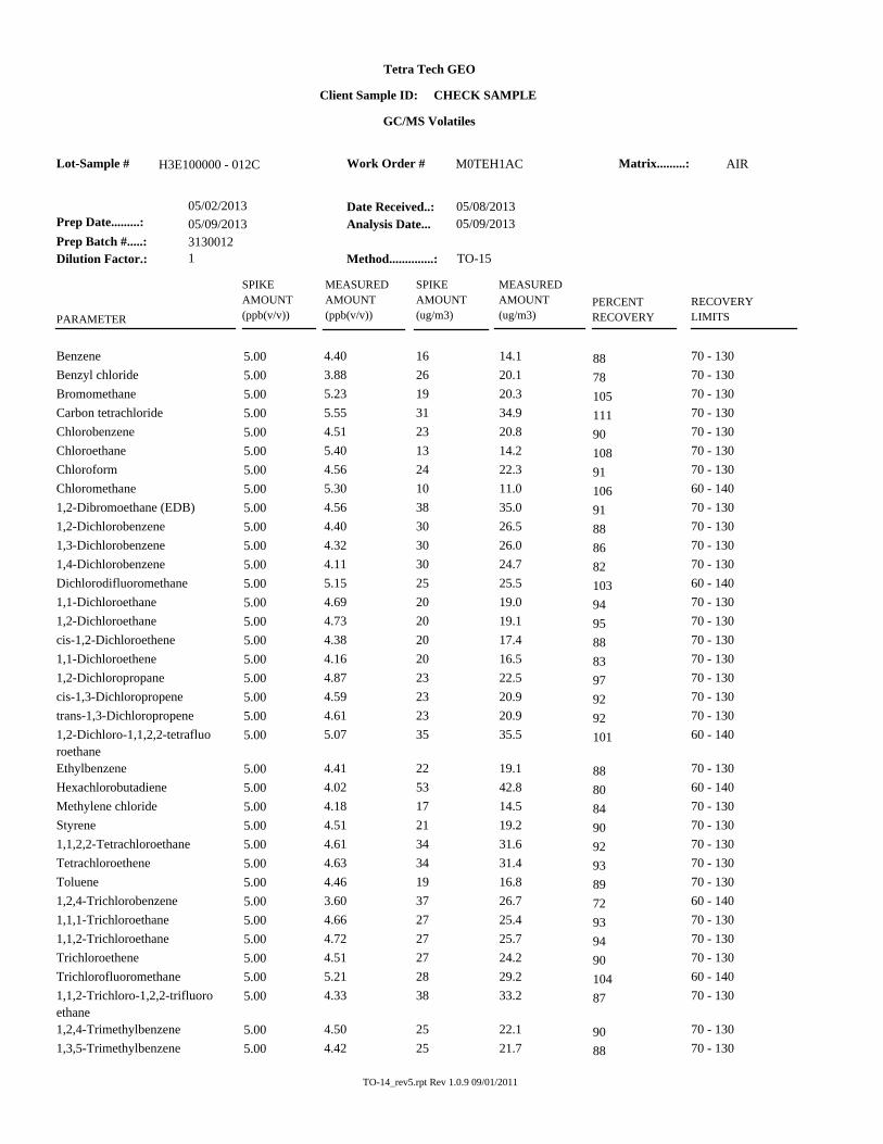
Client Sample ID: CHECK SAMPLE
M0TEH1AC AIRH3E100000 - 012C
TO-15Method..............:
05/09/2013Analysis Date...
05/08/2013Date Received..:
1Dilution Factor.:
3130012Prep Batch #.....:
05/09/2013Prep Date.........:
05/02/2013
PARAMETER
PERCENT
RECOVERY
RECOVERY
LIMITS
MEASURED
AMOUNT
(ug/m3)
MEASURED
AMOUNT
(ppb(v/v))
SPIKE
AMOUNT
(ppb(v/v))
SPIKE
AMOUNT
(ug/m3)
70 - 13014.1 165.00 4.40Benzene 88
70 - 13020.1 265.00 3.88Benzyl chloride 78
70 - 13020.3 195.00 5.23Bromomethane 105
70 - 13034.9 315.00 5.55Carbon tetrachloride 111
70 - 13020.8 235.00 4.51Chlorobenzene 90
70 - 13014.2 135.00 5.40Chloroethane 108
70 - 13022.3 245.00 4.56Chloroform 91
60 - 14011.0 105.00 5.30Chloromethane 106
70 - 13035.0 385.00 4.561,2-Dibromoethane (EDB) 91
70 - 13026.5 305.00 4.401,2-Dichlorobenzene 88
70 - 13026.0 305.00 4.321,3-Dichlorobenzene 86
70 - 13024.7 305.00 4.111,4-Dichlorobenzene 82
60 - 14025.5 255.00 5.15Dichlorodifluoromethane 103
70 - 13019.0 205.00 4.691,1-Dichloroethane 94
70 - 13019.1 205.00 4.731,2-Dichloroethane 95
70 - 13017.4 205.00 4.38cis-1,2-Dichloroethene 88
70 - 13016.5 205.00 4.161,1-Dichloroethene 83
70 - 13022.5 235.00 4.871,2-Dichloropropane 97
70 - 13020.9 235.00 4.59cis-1,3-Dichloropropene 92
70 - 13020.9 235.00 4.61trans-1,3-Dichloropropene 92
60 - 14035.5 355.00 5.071,2-Dichloro-1,1,2,2-tetrafluo
roethane 101
70 - 13019.1 225.00 4.41Ethylbenzene 88
60 - 14042.8 535.00 4.02Hexachlorobutadiene 80
70 - 13014.5 175.00 4.18Methylene chloride 84
70 - 13019.2 215.00 4.51Styrene 90
70 - 13031.6 345.00 4.611,1,2,2-Tetrachloroethane 92
70 - 13031.4 345.00 4.63Tetrachloroethene 93
70 - 13016.8 195.00 4.46Toluene 89
60 - 14026.7 375.00 3.601,2,4-Trichlorobenzene 72
70 - 13025.4 275.00 4.661,1,1-Trichloroethane 93
70 - 13025.7 275.00 4.721,1,2-Trichloroethane 94
70 - 13024.2 275.00 4.51Trichloroethene 90
60 - 14029.2 285.00 5.21Trichlorofluoromethane 104
70 - 13033.2 385.00 4.331,1,2-Trichloro-1,2,2-trifluoro
ethane 87
70 - 13022.1 255.00 4.501,2,4-Trimethylbenzene 90
70 - 13021.7 255.00 4.421,3,5-Trimethylbenzene 88
TO-14_rev5.rpt Rev 1.0.9 09/01/2011
Tetra Tech GEO
Matrix.........: Work Order #Lot-Sample #
GC/MS Volatiles
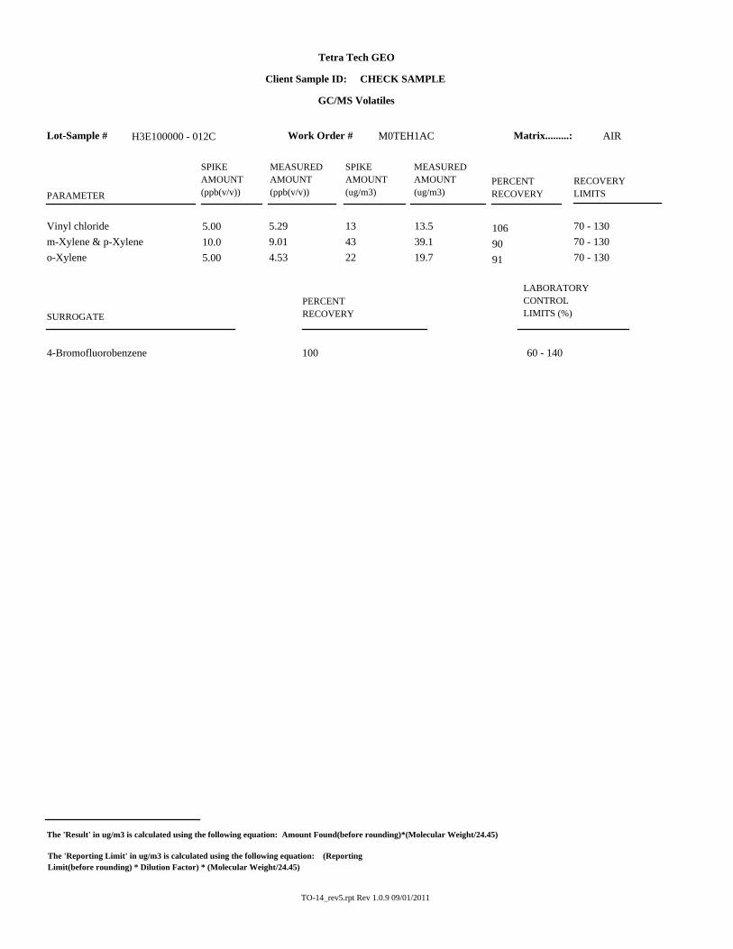
Client Sample ID: CHECK SAMPLE
M0TEH1AC AIRH3E100000 - 012C
PARAMETER
PERCENT
RECOVERY
RECOVERY
LIMITS
MEASURED
AMOUNT
(ug/m3)
MEASURED
AMOUNT
(ppb(v/v))
SPIKE
AMOUNT
(ppb(v/v))
SPIKE
AMOUNT
(ug/m3)
70 - 13013.5 135.00 5.29Vinyl chloride 106
70 - 13039.1 4310.0 9.01m-Xylene & p-Xylene 90
70 - 13019.7 225.00 4.53o-Xylene 91
LABORATORY
CONTROL
LIMITS (%)
PERCENT
RECOVERYSURROGATE
60 - 1404-Bromofluorobenzene 100
The 'Result' in ug/m3 is calculated using the following equation: Amount Found(before rounding)*(Molecular Weight/24.45)
The 'Reporting Limit' in ug/m3 is calculated using the following equation: (Reporting
Limit(before rounding) * Dilution Factor) * (Molecular Weight/24.45)
TO-14_rev5.rpt Rev 1.0.9 09/01/2011

Tetra Tech GEO
Matrix.........: Work Order #Lot-Sample #
GC/MS Volatiles
Client Sample ID: INTRA-LAB BLANK
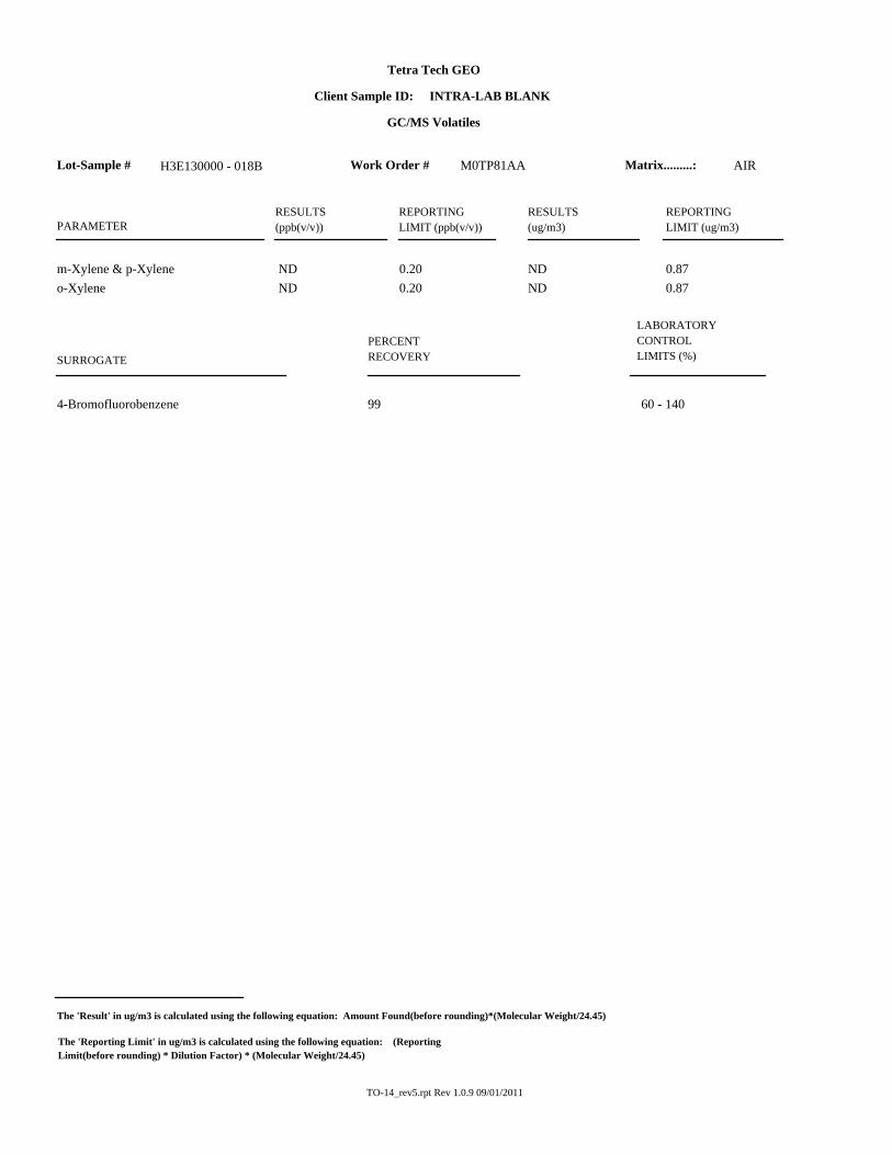
M0TP81AA AIRH3E130000 - 018B
TO-15Method..............:
05/10/2013Analysis Date...
05/09/2013Date Received..:
1Dilution Factor.:
3133018Prep Batch #.....:
05/10/2013Prep Date.........:
05/06/2013
PARAMETERRESULTS
(ug/m3)
RESULTS
(ppb(v/v))
REPORTING
LIMIT (ppb(v/v))
REPORTING
LIMIT (ug/m3)
ND 0.64Benzene ND 0.20
ND 2.1Benzyl chloride ND 0.40
ND 0.78Bromomethane ND 0.20
ND 1.3Carbon tetrachloride ND 0.20
ND 0.92Chlorobenzene ND 0.20
ND 0.53Chloroethane ND 0.20
ND 0.98Chloroform ND 0.20
ND 1.0Chloromethane ND 0.50
ND 1.51,2-Dibromoethane (EDB) ND 0.20
ND 1.21,2-Dichlorobenzene ND 0.20
ND 1.21,3-Dichlorobenzene ND 0.20
ND 1.21,4-Dichlorobenzene ND 0.20
ND 0.99Dichlorodifluoromethane ND 0.20
ND 0.811,1-Dichloroethane ND 0.20
ND 0.811,2-Dichloroethane ND 0.20
ND 0.79cis-1,2-Dichloroethene ND 0.20
ND 0.791,1-Dichloroethene ND 0.20
ND 0.921,2-Dichloropropane ND 0.20
ND 0.91cis-1,3-Dichloropropene ND 0.20
ND 0.91trans-1,3-Dichloropropene ND 0.20
ND 1.41,2-Dichloro-1,1,2,2-tetrafluoroeth
ane
ND 0.20
ND 0.87Ethylbenzene ND 0.20
ND 11Hexachlorobutadiene ND 1.0
ND 1.7Methylene chloride ND 0.50
ND 0.85Styrene ND 0.20
ND 1.41,1,2,2-Tetrachloroethane ND 0.20
ND 1.4Tetrachloroethene ND 0.20
ND 0.75Toluene ND 0.20
ND 7.41,2,4-Trichlorobenzene ND 1.0
ND 1.11,1,1-Trichloroethane ND 0.20
ND 1.11,1,2-Trichloroethane ND 0.20
ND 1.1Trichloroethene ND 0.20
ND 1.1Trichlorofluoromethane ND 0.20
ND 1.51,1,2-Trichloro-1,2,2-trifluoroetha
ne
ND 0.20
ND 0.981,2,4-Trimethylbenzene ND 0.20
ND 0.981,3,5-Trimethylbenzene ND 0.20
ND 0.51Vinyl chloride ND 0.20
TO-14_rev5.rpt Rev 1.0.9 09/01/2011
Tetra Tech GEO
Matrix.........: Work Order #Lot-Sample #
GC/MS Volatiles
Client Sample ID: INTRA-LAB BLANK
M0TP81AA AIRH3E130000 - 018B
PARAMETERRESULTS
(ug/m3)
RESULTS
(ppb(v/v))
REPORTING
LIMIT (ppb(v/v))
REPORTING
LIMIT (ug/m3)
ND 0.87m-Xylene & p-Xylene ND 0.20
ND 0.87o-Xylene ND 0.20
LABORATORY
CONTROL
LIMITS (%)
PERCENT
RECOVERYSURROGATE
60 - 1404-Bromofluorobenzene 99
The 'Result' in ug/m3 is calculated using the following equation: Amount Found(before rounding)*(Molecular Weight/24.45)
The 'Reporting Limit' in ug/m3 is calculated using the following equation: (Reporting
Limit(before rounding) * Dilution Factor) * (Molecular Weight/24.45)
TO-14_rev5.rpt Rev 1.0.9 09/01/2011

Tetra Tech GEO
Matrix.........: Work Order #Lot-Sample #
GC/MS Volatiles
Client Sample ID: CHECK SAMPLE
M0TP81AC AIRH3E130000 - 018C
TO-15Method..............:
05/10/2013Analysis Date...
05/09/2013Date Received..:
1Dilution Factor.:
3133018Prep Batch #.....:
05/10/2013Prep Date.........:
05/06/2013
PARAMETER
PERCENT
RECOVERY
RECOVERY
LIMITS
MEASURED
AMOUNT
(ug/m3)
MEASURED
AMOUNT
(ppb(v/v))
SPIKE
AMOUNT
(ppb(v/v))
SPIKE
AMOUNT
(ug/m3)
70 - 13012.2 165.00 3.83Benzene 77
70 - 13021.9 265.00 4.23Benzyl chloride 85
70 - 13015.9 195.00 4.10Bromomethane 82
70 - 13030.6 315.00 4.86Carbon tetrachloride 97
70 - 13018.5 235.00 4.02Chlorobenzene 80
70 - 13010.0 135.00 3.80Chloroethane 76
70 - 13019.3 245.00 3.95Chloroform 79
60 - 1407.56 105.00 3.66Chloromethane 73
70 - 13032.3 385.00 4.211,2-Dibromoethane (EDB) 84
70 - 13025.4 305.00 4.221,2-Dichlorobenzene 84
70 - 13025.4 305.00 4.221,3-Dichlorobenzene 84
70 - 13025.3 305.00 4.211,4-Dichlorobenzene 84
60 - 14022.5 255.00 4.54Dichlorodifluoromethane 91
70 - 13015.9 205.00 3.941,1-Dichloroethane 79
70 - 13015.6 205.00 3.871,2-Dichloroethane 77
70 - 13016.4 205.00 4.14cis-1,2-Dichloroethene 83
70 - 13017.2 205.00 4.341,1-Dichloroethene 87
70 - 13017.6 235.00 3.801,2-Dichloropropane 76
70 - 13019.4 235.00 4.27cis-1,3-Dichloropropene 85
70 - 13020.5 235.00 4.51trans-1,3-Dichloropropene 90
60 - 14032.7 355.00 4.681,2-Dichloro-1,1,2,2-tetrafluo
roethane 94
70 - 13017.3 225.00 3.98Ethylbenzene 80
60 - 14043.5 535.00 4.08Hexachlorobutadiene 82
70 - 13014.0 175.00 4.03Methylene chloride 81
70 - 13017.0 215.00 4.00Styrene 80
70 - 13026.8 345.00 3.911,1,2,2-Tetrachloroethane 78
70 - 13027.6 345.00 4.07Tetrachloroethene 81
70 - 13014.5 195.00 3.84Toluene 77
60 - 14039.1 375.00 5.271,2,4-Trichlorobenzene 105
70 - 13022.8 275.00 4.171,1,1-Trichloroethane 83
70 - 13021.2 275.00 3.881,1,2-Trichloroethane 78
70 - 13023.0 275.00 4.28Trichloroethene 86
60 - 14024.6 285.00 4.38Trichlorofluoromethane 88
70 - 13032.7 385.00 4.261,1,2-Trichloro-1,2,2-trifluoro
ethane 85
70 - 13019.7 255.00 4.011,2,4-Trimethylbenzene 80
70 - 13019.6 255.00 3.991,3,5-Trimethylbenzene 80
TO-14_rev5.rpt Rev 1.0.9 09/01/2011

Tetra Tech GEO
Matrix.........: Work Order #Lot-Sample #
GC/MS Volatiles
Client Sample ID: CHECK SAMPLE
M0TP81AC AIRH3E130000 - 018C
PARAMETER
PERCENT
RECOVERY
RECOVERY
LIMITS
MEASURED
AMOUNT
(ug/m3)
MEASURED
AMOUNT
(ppb(v/v))
SPIKE
AMOUNT
(ppb(v/v))
SPIKE
AMOUNT
(ug/m3)
70 - 1309.93 135.00 3.89Vinyl chloride 78
70 - 13034.0 4310.0 7.82m-Xylene & p-Xylene 78
70 - 13017.3 225.00 3.98o-Xylene 80
LABORATORY
CONTROL
LIMITS (%)
PERCENT
RECOVERYSURROGATE
60 - 1404-Bromofluorobenzene 102
The 'Result' in ug/m3 is calculated using the following equation: Amount Found(before rounding)*(Molecular Weight/24.45)
The 'Reporting Limit' in ug/m3 is calculated using the following equation: (Reporting
Limit(before rounding) * Dilution Factor) * (Molecular Weight/24.45)
TO-14_rev5.rpt Rev 1.0.9 09/01/2011

ATTACHMENT 6
WASTE DISPOSAL DOCUMENTATION


ATTACHMENT 7
UPDATED OPERATION AND MAINTENANCE MANUAL
(PROVIDED SEPARATELY)