CONSTRUCTION AND INSTALLATION OF PERMANENT SUB-SLAB SOIL GAS WELLS
13
STANDARD OPERATING PROCEDURES SOP: 2082 Page: 1 of 13 Rev. 0.0 DATE: 03/29/07 CONSTRUCTION AND INSTALLATION OF PERMANENT SUB-SLAB SOIL GAS WELLS CONTENTS 1.0 SCOPE AND APPLICATION 2.0 METHOD SUMMARY 3.0 SAMPLE PRESERVATION, CONTAINERS, HANDLING AND STORAGE 4.0 INTERFERENCES AND POTENTIAL PROBLEMS 5.0 EQUIPMENT/APPARATUS 6.0 REAGENTS 7.0 PROCEDURES 7.1 Probe Assembly and Installation 7.2 Sampling Set-Up 7.3 Repairing a Loose Probe 8.0 CALCULATIONS 9.0 QUALITY ASSURANCE/QUALITY CONTROL 10.0 DATA VALIDATION 11.0 HEALTH AND SAFETY 12.0 REFERENCES 13.0 APPENDICES
Transcript of CONSTRUCTION AND INSTALLATION OF PERMANENT SUB-SLAB SOIL GAS WELLS

STANDARD OPERATING PROCEDURES
SOP: 2082 Page: 1 of 13
Rev. 0.0
DATE: 03/29/07
CONSTRUCTION AND INSTALLATION OF PERMANENT SUB-SLAB SOIL GAS WELLS
CONTENTS
1.0 SCOPE AND APPLICATION
2.0 METHOD SUMMARY
3.0 SAMPLE PRESERVATION, CONTAINERS, HANDLING AND STORAGE
4.0 INTERFERENCES AND POTENTIAL PROBLEMS
5.0 EQUIPMENT/APPARATUS
6.0 REAGENTS
7.0 PROCEDURES
7.1 Probe Assembly and Installation
7.2 Sampling Set-Up
7.3 Repairing a Loose Probe
8.0 CALCULATIONS
9.0 QUALITY ASSURANCE/QUALITY CONTROL
10.0 DATA VALIDATION
11.0 HEALTH AND SAFETY
12.0 REFERENCES
13.0 APPENDICES

STANDARD OPERATING PROCEDURES
SOP: 2082 Page: 2 of 13
Rev. 0.0
DATE: 03/29/07
CONSTRUCTION AND INSTALLATION OF PERMANENT SUB-SLAB SOIL GAS WELLS
1.0 SCOPE AND APPLICATION
This standard operating procedure (SOP) outlines the procedure used for the construction and installation of permanent sub-slab soil gas wells. The wells are used to sample the gas contained in the interstitial
spaces beneath the concrete floor slab of dwellings and other structures.
Soil gas monitoring provides a quick means of detecting volatile organic compounds (VOCs) in the soil
subsurface. Using this method, underground VOC contamination can be identified and the source, extent
and movement of pollutants can be traced.
2.0 METHOD SUMMARY
Using an electric Hammer Drill or Rotary Hammer, an inner or pilot hole is drilled into the concrete slab to
a depth of approximately 2" with the d" diameter drill bit. Using the pilot hole as the center, an outer hole is drilled to an approximate depth of 1d" using the 1" diameter drill bit. The 1" diameter drill bit is then
replaced with the d" drill bit. The pilot hole is drilled through the slab and several inches into the sub-slab
material. Once drilling is completed, a stainless steel probe is assembled and inserted into the pre-drilled
hole. The probe is mounted flush with the surrounding slab so it will not interfere with pedestrian or
vehicular traffic and cemented into place. A length of Teflon tubing is attached to the probe assembly and
to a sample container or system.
3.0 SAMPLE PRESERVATION, CONTAINERS, HANDLING AND STORAGE
3.1 SUMMA Canister Sampling
After the sub-slab soil gas sample is collected, the canister valve is closed, an identification tag is
attached to the canister and the canister is transported to a laboratory under chain of custody for
analysis. Upon receipt at the laboratory, the data documented on the canister tag is recorded.
Sample holding times are compound dependent, but most VOCs can be recovered from the
canister under normal conditions near the original concentration for up to 30 days. Refer to
SERAS SOP #1704, SUMMA Canister Sampling for more details.
3.2 Tedlar Bag Sampling
Tedlar bags most commonly used for sampling have a 1-liter volume capacity. After sampling,
the Tedlar bags are stored in either a clean cooler or an opaque plastic bag at ambient temperature
to prevent photodegradation. It is essential that sample analysis be undertaken within 24 to 48 hours following sample collection since VOCs may escape or become altered. Refer to SERAS
SOP #2102, Tedlar Bag Sampling for more details.
4.0 INTERFERENCES AND POTENTIAL PROBLEMS
The thickness of a concrete slab may vary from structure to structure. A structure may also have a single
slab where the thickness varies. A slab may contain steel reinforcement (REBAR). Drill bits of various
sizes and cutting ability will be required to penetrate slabs of varying thicknesses or those that are steel-
reinforced.
STANDARD OPERATING PROCEDURES
SOP: 2082 Page: 3 of 13
Rev. 0.0
DATE: 03/29/07
CONSTRUCTION AND INSTALLATION OF PERMANENT SUB-SLAB SOIL GAS WELLS
5.0 EQUIPMENT/APPARATUS
Hammer Drill or Rotary Hammer
Alternating current (AC) extension cord
AC generator, if AC power is not available on site
Hammer or Rotary Hammer drill bit, d" diameter
Hammer or Rotary Hammer drill bit, 1"diameter
Portable vacuum cleaner
1 - ¾" open end wrench or 1-medium adjustable wrench
2 - 9/16" open end wrenches or 2-small adjustable wrenches
Hex head wrench, ¼"
Tubing cutter
Disposable cups, 5 ounce (oz)
Disposable mixing device (i.e., popsicle stick, tongue depressor, etc.)
Swagelok SS-400-7-4 Female Connector, ¼" National Pipe Thread (NPT) to ¼" Swagelok connector
Swagelok SS-400-1-4 Male Connector, ¼"NPT to ¼" Swagelok connector
¼" NPT flush mount hex socket plug, Teflon-coated
¼" outer diameter (OD) stainless steel tubing, pre-cleaned, instrument grade
¼" OD Teflon tubing
Teflon thread tape
1/8 ” OD stainless steel rod, 12” to 24” length
Swagelok Tee, optional (SS-400-3-4TMT or SS-400-3-4TTM)
6.0 REAGENTS
Tap water, for mixing anchoring cement
Anchoring cement
Modeling clay
7.0 PROCEDURES
7.1 Probe Assembly and Installation
1. Drill a d" diameter inner or pilot hole to a depth of 2" (Figure 1, Appendix A).
2. Using the d" pilot hole as your center, drill a 1" diameter outer hole to a depth of 1d".
Vacuum out any cuttings from the hole (Figure 2, Appendix A).
3. Continue drilling the d inner or pilot hole through the slab and a few inches into the sub-slab
material (Figure 3, Appendix A). Vacuum out any cuttings from the outer hole.
4. Determine the length of stainless steel tubing required to reach from the bottom of the outer
hole, through the slab and into the open cavity below the slab. To avoid obstruction of the
probe tube, ensure that it does not contact the sub-slab material. Using a tube cutter, cut the
tubing to the desired length.
5. Attach the measured length (typically 12O) of ¼" OD stainless tubing to the female connector

STANDARD OPERATING PROCEDURES
SOP: 2082 Page: 4 of 13
Rev. 0.0
DATE: 03/29/07
CONSTRUCTION AND INSTALLATION OF PERMANENT SUB-SLAB SOIL GAS WELLS
(SS-400-7-4) with the Swagelok nut. Tighten the nut.
6. Insert the ¼" hex socket plug into the female connector. Tighten the plug. Do not over
tighten. If excessive force is required to remove the plug during the sample set up phase, the probe may break loose from the anchoring cement.
7. Place a small amount of modeling clay around the stainless steel tubing adjacent to the
Swagelok nut, which connects the stainless steel tubing to the female connector. Use a
sufficient amount of modeling clay so that the completed probe, when placed in the outer
hole, will create a seal between the outer hole and the inner hole. The clay seal will prevent
any anchoring cement from flowing into the inner hole during the final step of probe
installation.
8. Place the completed probe into the outer hole. The probe tubing should not contact the sub-
slab material and the top of the female connector should be flush with the surface of the slab and centered in the outer hole (Figure 4, Appendix A). If the top of the completed probe is
not flush with the surface of the slab, due to the outer hole depth being greater than 1d",
additional modeling clay may be placed around the stainless steel tubing adjacent to the
Swagelok nut, which connects the stainless steel tubing to the female connector. Use a
sufficient amount of clay to raise the probe until it is flush with the surface of the slab while
ensuring that a portion of the clay will still contact and seal the inner hole.
9. Mix a small amount of the anchoring cement. Fill the space between the probe and the outside
of the outer hole. Allow the cement to cure according to manufacturers instructions before
sampling.
7.2 Sampling Set-Up
1. Wrap one layer of Teflon thread tape onto the NPT end of the male connector (SS-400-1-4).
Refer to Figure 5, Appendix A.
2. Remove the ¼" hex socket plug from the female connector (SS-400-7-4). Refer to Section
7.3 if the probe breaks loose from the anchoring cement during this step.
3. To ensure that the well has not been blocked by the collapse of the inner hole below the end
of the stainless steel tubing, a stainless steel rod, 1/8” diameter, may be passed through the
female connector and the stainless steel tubing. The rod should pass freely to a depth greater
than the length of the stainless steel tubing, indicating an open space or loosely packed soil below the end of the stainless steel tubing. Either condition should allow a soil gas sample to
be collected.
If the well appears blocked, the stainless steel rod may be used as a ramrod in an attempt to
open the well. If the well cannot be opened, the probe should be reinstalled or a new probe
installed in an alternate location.
4. Screw and tighten the male connector (SS-400-1-4) into the female connector (SS-400-7-4).
Do not over tighten. This may cause the probe to break loose from the anchoring cement
during this step or when the male connector is removed upon completion of the sampling

STANDARD OPERATING PROCEDURES
SOP: 2082 Page: 5 of 13
Rev. 0.0
DATE: 03/29/07
CONSTRUCTION AND INSTALLATION OF PERMANENT SUB-SLAB SOIL GAS WELLS
event. Refer to Section 7.3 if the probe breaks loose from the anchoring cement during this
step.
5. If a collocated sub-slab sample or split sample is desired, a stainless steel Swagelok Tee (SS-400-3-4TMT or SS-400-3-4TTM) may be used in place of the Swagelok male connector (SS-
400-1-4).
6. Attach a length of ¼"OD Teflon tubing to the male connector with a Swagelok nut. The
Teflon tubing is then connected to the sampling container or system to be used for sample
collection.
7. After sample collection remove the male connector from the probe and reinstall the hex
socket plug. Do not over tighten the hex socket plug. If excessive force is required to
remove the plug during the next sampling event the probe may break loose from the
anchoring cement. Refer to Section 7.3 if the probe breaks loose from the anchoring cement during this step.
7.3 Repairing a Loose Probe
1. If the probe breaks loose from the anchoring cement while removing or installing the hex
head plug or the male connector (SS-400-1-4), lift the probe slightly above the surface of the
concrete slab.
2. Hold the female connector (SS-400-7-4) with the ¾" open end wrench.
3. Complete the step being taken during which the probe broke loose, following the instructions
contained in this SOP (i.e., Do not over tighten the hex socket plug or male connector).
4. Push the probe back down into place and reapply the anchoring cement.
5. Modeling clay may be used as a temporary patch to effect a seal around the probe until the
anchoring cement can be reapplied.
8.0 CALCULATIONS
This section is not applicable to this SOP.
9.0 QUALITY ASSURANCE/QUALITY CONTROL
An additional collocated soil gas well is installed with the frequency of 10 percent (%) or as specified in the
site-specific Quality Assurance Project Plan (QAPP). The following general Quality Assurance (QA)
procedures apply:
1. A rough sketch of the area is drawn where the ports are installed with the major areas noted on the
sketch. This information may be transferred to graphing software for incorporation into the final
deliverable.
2. A global positioning system (GPS) unit may be used to document coordinates outside of a structure as

STANDARD OPERATING PROCEDURES
SOP: 2082 Page: 6 of 13
Rev. 0.0
DATE: 03/29/07
CONSTRUCTION AND INSTALLATION OF PERMANENT SUB-SLAB SOIL GAS WELLS
a reference point.
3. Equipment used for the installation of sampling ports should be cleaned by heating, inspected and
tested prior to deployment.
10.0 DATA VALIDATION
This section is not applicable to this SOP.
11.0 HEALTH AND SAFETY
When working with potentially hazardous materials, follow Environmental Protection Agency (EPA),
Occupational Safety and Health Administration (OSHA) and Lockheed Martin corporate health and safety
procedures. All site activities should be documented in the site-specific health and safety plan (HASP).
12.0 REFERENCES
This section is not applicable to this SOP.
13.0 APPENDICES
A - Figures
STANDARD OPERATING PROCEDURES
SOP: 2082 Page: 7 of 13
Rev. 0.0
DATE: 03/29/07
CONSTRUCTION AND INSTALLATION OF PERMANENT SUB-SLAB SOIL GAS WELLS
APPENDIX A
Soil Gas Installation Figures
SOP #2082 March 2007

STANDARD OPERATING PROCEDURES
SOP: 2082 Page: 8 of 13
Rev. 0.0
DATE: 03/29/07
CONSTRUCTION AND INSTALLATION OF PERMANENT SUB-SLAB SOIL GAS WELLS

STANDARD OPERATING PROCEDURES
SOP: 2082 Page: 9 of 13
Rev. 0.0
DATE: 03/29/07
CONSTRUCTION AND INSTALLATION OF PERMANENT SUB-SLAB SOIL GAS WELLS

STANDARD OPERATING PROCEDURES
SOP: 2082 Page: 10 of 13
Rev. 0.0
DATE: 03/29/07
CONSTRUCTION AND INSTALLATION OF PERMANENT SUB-SLAB SOIL GAS WELLS

STANDARD OPERATING PROCEDURES
SOP: 2082 Page: 11 of 13
Rev. 0.0
DATE: 03/29/07
CONSTRUCTION AND INSTALLATION OF PERMANENT SUB-SLAB SOIL GAS WELLS
STANDARD OPERATING PROCEDURES
SOP: 2082 Page: 12 of 13
Rev. 0.0
DATE: 03/29/07
CONSTRUCTION AND INSTALLATION OF PERMANENT SUB-SLAB SOIL GAS WELLS
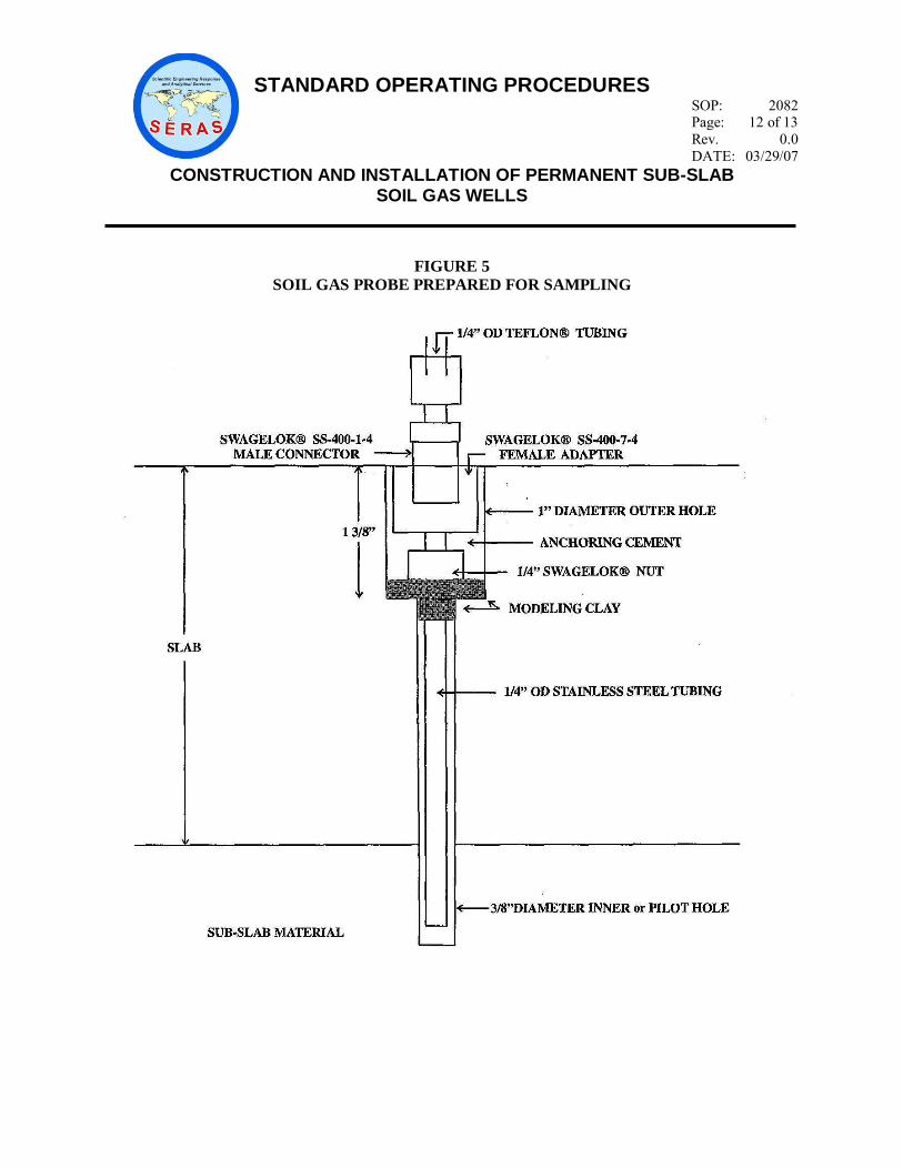
FIGURE 5
SOIL GAS PROBE PREPARED FOR SAMPLING
STANDARD OPERATING PROCEDURES
SOP: 2082 Page: 13 of 13
Rev. 0.0
DATE: 03/29/07
CONSTRUCTION AND INSTALLATION OF PERMANENT SUB-SLAB SOIL GAS WELLS
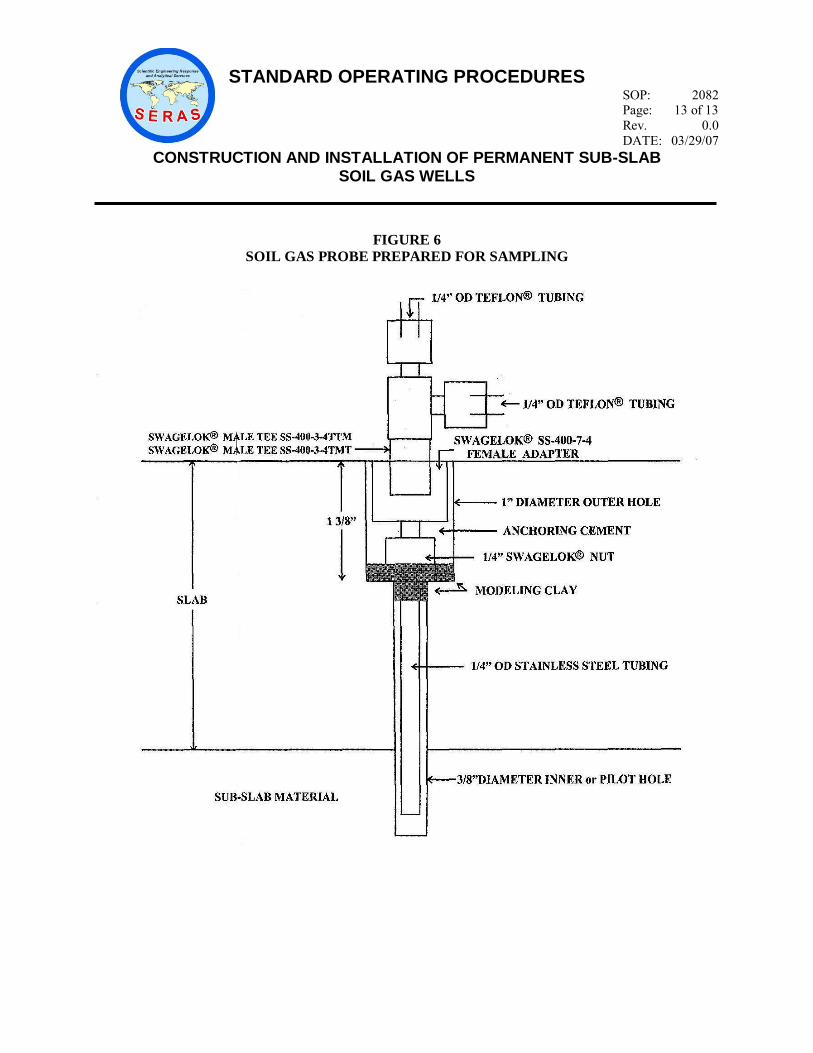
FIGURE 6
SOIL GAS PROBE PREPARED FOR SAMPLING