
CONSTRUCTING A MOVIE-WORTHY MINIATURE
20
Accurizing the U.S.S. Enterprise 1 BACK NEXT ➤ ➤ This article was originally written in 1991. Please note there may be some slight inaccuracies, and, well I was only 15 when I wrote it. This is the full text submitted to FineScale Modeler (plus some new minor notes), which was greatly edit when printed. –CP CONSTRUCTING A MOVIE-WORTHY MINIATURE ACCURIZING AMT’S ENTERPRISE MODEL WRITTEN BY CHRIS PAVEGLIO (original printing by Kalmbach Publishing, FineScale Modeler, January 1992)
Transcript of CONSTRUCTING A MOVIE-WORTHY MINIATURE

Accurizing the U.S.S. Enterprise 1BACK NEXT ➤➤
This article was originally written in 1991. Please note there may be some slight inaccuracies, and, well I was only 15 when I wrote it. This is the full text submitted to FineScale Modeler (plussome new minor notes), which was greatly edit when printed. –CP
CONSTRUCTING A MOVIE-WORTHY MINIATURE
ACCURIZING AMT’S ENTERPRISE MODEL
WRITTEN BY CHRIS PAVEGLIO(original printing by Kalmbach Publishing, FineScale Modeler, January 1992)

T H E E NTE R P R ISE
One of the most relaxing forms of modeling must surely be that
of modeling spacecraft. Science fiction miniatures require little,
if any, exactness of detail because the viewer rarely spots minor
inconsistencies that may be apparent on a scale tank or aircraft.
Space vehicles can be built in any scale, allowing the builder to
use many left over, around-the-house pieces, and enough imagi-
nation to satisfy his building appetite.
But, the universe of Star Trek is slightly different: there is a
purpose for everything, so you just can’t glue on a golf ball and
say it’s a fuel tank. And AMT/Ertl can’t just scribe little panels
on the body or change the paint scheme. That is why this article
is written: to help you build a movie worthy miniature from
AMT’s kit without all the hours of research needed to fix the
mistakes.
Building procedures will be divided by ship sections, but you
may want to do all the major puttying and sanding at the same
time. Remember to wash off all parts first.
You may wish to write to AMT/Ertl for another set of decals,
because another small “Enterprise” is needed for the rear of the
secondary hull under the shuttle bay doors. The address is High-
ways 136 and 20, Dyersville, IA 52040.
I would also suggest that you watch Star Trek 1, 2, & 6.
These are excellent visual guides for the tonal variations in the
paint scheme. One last note: AMT is presently issuing a light
up, sound effect Enterprise model you may want to check out.
MATERIALS NEEDED:1 AMT/Ertl USS Enterprise ST 4 or 5 kit
airbrush
2 tubes Squadron green putty or similar
low tack frisket paper (Dr. Ph. Martin’s brand, for example)
drafting tape
Micro Krystal-Kleer
files, many shapes and sizes
Dremel drill
plastic scribing tool
X-Acto knives
squeegee
glue-regular and epoxy
sheet styrene .030
wet or dry sandpaper- 240, 320, 400, 600
red striping decals
Tamiya paints- by #
1 X18 semi-gloss black
1 XF1 flat aluminum
1 X11 chrome silver
1 XF66 light grey
3 XF2 flat white
3 X2 gloss white
1 XF21 sky
2 XF54
Accurizing the U.S.S. Enterprise 2BACK NEXT ➤➤

Testor’s paints- by name
flat red
flat sky blue
flat tan
flat yellow
flat black
flat rubber
copper
Polly S (brand) Earth Yellow
THE DISHBeginning at the top, remove all flash, alignment pins, and
the large bump from the bridge (pc. 3). Using an X-Acto saw
blade cut the upper dome off, using the middle ring as the slicing
point. Sand the top of the bridge until cut marks are gone and
the dome is smooth. File the bottom of the little dome down
until flat, leaving only one ring and the four squares. Center and
glue with squares facing as they were before the cut. Cut the
sides and top of pc. 4 so that it will fit inside of pc. 3. Glue in.
Putty in the ports on either side of the circular port. Sand or file
till flush with original rear wall. Sand off the lines on the sides of
the bridge (fig. 1). Using a 5/32” drill for the moto-tool, slightly
enlarge the docking port on the rear of the bridge. This is the
correct size for the four other ports on the ship.
The VIP lounge on pc. 1 (to which the bridge is cemented)
is nicely detailed, but needs a little work. The front portion is
okay, but the rear edge should be slanted more at a 45 degree
angle. File this down until it is flatter and has no swelling look
to it. The aft should be a mirror image of the front, albeit longer.
Using a very small file open the large windows, leaving as thin a
separation as possible. The edges should be straight and end in a
curve, not a sharp angle, at the corners. Using a tiny drill bit
open the 8 circle and 2 oval windows slightly. Put a glob of putty
behind these 10 windows only. Make a floor for the VIP lounge
from styrene. You may want to try to make little pieces of furni-
ture from styrene or putty. Do not glue this in yet, or open the
arc shaped, thin plastic openings on the top of the lounge.
On the dish itself, cut off the phasers and running lights on
both top and bottom halves. On the impulse engine, the section
Accurizing the U.S.S. Enterprise 3BACK NEXT ➤➤
Figure 1: Chop down that dome, and if you like,lop off the huge light dimple, sand off the boxdetail on the side.
Before After

with the four and a half raised squares has to be filed flat.
Engrave in five squares, equally sized and spaced (fig. 2). On the
six pc. 6’s, fill in the lower left window hole. Using a tiny drill
bit, drill out a new window centered below the upper left con-
secutive two (fig. 3), and also open up all the other oval and cir-
cular holes. Now cut off the tabs on the ends of the six pieces.
On pc. 2, using the same drill bit, open up the 18 holes in the
bottom of the dish, and only the 8 windows on the port side rear
of the dish edge. Drill out a shallow docking port hole on the
starboard side of the dish. On the starboard side rear of the dish
edge drill out 8 holes, four on top of four, at the place where
there are lightly scribed windows in a six on two configuration.
Use a tiny square file to file out 8 square windows (fig. 4). Glue
the six window sections in, making sure outside edge alignment
is perfect.
Now comes the fun part. Using a squeegee, apply putty to
the entire surface of the dish. Coat a few sections of “pie” at a
time. Immediately use the scriber to rescribe only the deflector
grid. The purpose of this is to eliminate the tiny randomly posi-
tioned squares (fig. 5) and leave the evenly sized, non-overlap-
ping “grid” showing (fig. 6). Make sure to rescribe the 20 small
access hatches on rows five and six, the holes on the reaction
control thrusters (at the ends of four deflector grid lines), the
mid-sized squares on row three in front of the impulse engine,
and the curved shapes also in front of the impulse engines; you
might want to use an X-Acto knife for these. Be very careful
when puttying by the VIP lounge and impulse engines. Do not
clean out the two holes in front of or beside the impulse engine.
On the bottom half do the same, but only putty the curved
section, not the flat outer ring and edge. Putty, scribe, putty,
scribe, putty, scribe...till it’s all done. Do not rescribe these
Accurizing the U.S.S. Enterprise 4BACK NEXT ➤➤
Figure 2: I had to fill in the window ports (left) toget a better shape. Impulse engine with properlines and ready for new low profile dome.
Figure 3: Fill in the left lower dish window, and drilla new one centered under the first two circle win-dows.
drill out fill

Accurizing the U.S.S. Enterprise 5BACK NEXT ➤➤
Figure 4: Recreation Room windows, 4 on 4.
Figure 5: OK, What the hell is this crap? Prepareto fill in these insane lines.
Figure 6: Hey now that’s looking smoother. Notenew inscribed hatches and improved docking door.These panels should be moved forward 1 ring.

places: inside the three feet on rows three and four or the single
line on row four on the starboard front section. Use a hand-held
Dremel bit to clean out the 18 bottom windows. Look on row
one, starboard for a panel with two lines the depth of the deflec-
tor grid. Scribe these out. You will not find them on the port
side.
Wet sand the dish halves starting at 320 grit, then 400, then
600. Take your time with this, because the surface is one of the
most important keys to having an excellent Enterprise model.
Reputty and resand as many times as necessary to achieve a glass
smooth, nick free surface. When you are finished sanding,
rescribe the deflector grid a few times to clean out excess putty
or dirt. One caution: be very careful not to put a curve on the
bottom outside ring that I told you not to putty. When you are
done with the dish surface, putty up the outside ring and outside
edge (with the windows). With a hand-held Dremel bit quickly
clean out the windows. Do not sand the edge yet, but using a flat
file, file smooth the outside ring, finishing the job with 400 and
600 grit sandpaper, wet. Now is the time to glue in the VIP
lounge floor to the top dish halve, use something durable and
slightly flexible, like epoxy.
The lower dish needs another foot, access panel, docking
port, and auxiliary access panel (fig. 7). The aux. panel should
be scribed into row five forward (counting out from center),
opposite the other small panel. Use a flexi six inch-ruler and a
sharp knife to start the scribe. After a few knife scribes, change
to using the scriber you used for the deflector grid cleaning. The
access panel and planetfall feet should be located on rows four
and five. The existing panels need removed and positioned for-
ward 1 ring section. All feet and panels should line up with the
rings on the back of the dish. The starboard side, row one, a pan-
el has the beginnings of docking port doors, which you were to
find and scribe out. Use your flexi-ruler to extend the two lines
and the deflector grid line, which lies at a 45 degree angle to the
hull midline, 1/8 of an inch toward the center of the hull. Using
a compass, draw an arc connecting these three lines, and draw it
around to the opposite port side panel. Using the flexi-ruler,
Accurizing the U.S.S. Enterprise 6BACK NEXT ➤➤
Figure 7: Scribe larger docking doors, scribe plan-et-fall feet and access doors, move phaser mountsto the outer section of ring.

knife, and scriber create the two other needed lines to form
another set of docking port doors. Scribe the arc to connect the
bottom of the doors. You will have to fill in the bottom of the
doors, the large access panel, and the foot.
Also, the phaser banks on the lower part of the dish need to
be moved from “inside” of the first row, to outside of it, or inside
the second row. It is just flipped to the other side of the line.
Clean out completely the windows on the bottom dish half
with the Dremel bit. Put a glob of putty behind every window,
but don’t fill the windows. Cover the four large VIP lounge win-
dows and bridge alignment holes with drafting tape. Glue the
two dish halves together. You may need to putty the edge seam
slightly, try not to get putty in the windows. Wet sand the edge
until it is glass smooth. Be careful as to not put a bow on the
edge; it needs to stay straight. The gaps between the dish halves,
window sections and hull, and lateral docking ports should not
show.
Scribe lightly with a knife only, lateral lines inside of the
impulse exhaust. Test fit the piece to the hull and file it as neces-
sary to fit properly, glue on. You will have to putty in the corners
and knife or file this down to achieve a solid angle. There is a
slight dimple on the bottom of the impulse exhaust you may also
want to fill. Take the tape off of the VIP lounge.
We finally reach the bottom of the dish. The lower sensor
dome (pc. 5) needs to have the 8 square exterior vents enlarged.
Use a knife to cut and scrape them open, or if you are good with
a Dremel, use a flat, then a pointed bit for the corners. Carefully
cut the excess plastic from inside the snoots so only a thin sheet
of plastic covers the hull illumination lights. Using a plastic
Helix or Berol template and a mechanical pencil, if you have
one, draw a 13/16 inch circle around the dome itself, and one 1
3/8 inch on the housing between snoots. With your knife, scribe
the smaller circle, but extend the imaginary line of the four
housing protrusions to the larger circle. Using a small square file,
cut down the housing on either side of the protrusion. File the
protrusions to a greater angle than the housing, but leaving
about a millimeter of original protrusion. Cut or file the very top
of this to make a circular housing with distinct edges (fig. 8). If
Accurizing the U.S.S. Enterprise 7BACK NEXT ➤➤
Figure 8: Before and After, Lower Sensors. Fileout nose, cut down outer ring. I didn’t make a newbigger dome for mine.
Before After

you are good at casting, recast the lower sensor assembly, and
modify the mold, making the dome itself wider (diameter of
13/16”), but no taller. Rebuild the four squares and detail lines, if
possible.
You may now glue the bridge to the VIP lounge, but leave
the sensor dome off. On to the next part.
THE NECKGlue pieces 8 and 9 together. Build a 15/16” extension off of
the top of the front tip, aligned with the separation line. With a
squeegee putty the surfaces, and fill in the docking ports. Do not
get putty in the photon exhaust (rear bottom). Clean out only
the six windows on the photon tube assembly quickly. Using
your scriber scribe out only the top hull separation line (fig. 9).
Do not follow this around the front, but extend it straight out.
Scribe out the short diagonal line and connect it to the top line.
When dry, wet sand until glass smooth like the other pieces.
Using your 5/32 drill bit, make two new docking ports, one
on either side of the photon assembly, in the filled hole. Take a
5/16” wide piece of tape and place it vertically 7/16” behind the
very tip of the photon assembly. This is the vertical engineering
shaft marker. Totally clean out the six lower windows, and drill
new windows according to the marker, in the same configuration
as before.
Using the patterns provided, make two new impulse engine
intercoolers (see painting section). Scribe the lines on with a
scriber, then glue them on over the old ‘coolers. You may need to
putty around the rear edges to achieve a “solid” look.
Cut off the little tabs on the back of pc. 10, on the front put
two big globs of putty on the two squares. When this is dry, carve
the putty in the shape of the new photon tubes (fig. 10). Don’t
glue this in now. Drill two holes beside the photon exhaust on
either side with a tiny bit.
THE SECONDARY HULLGlue pcs. 11 and 12 into 13 and 14. You may want to make
some extra reinfocement on these parts, there is a lot of stress on
Accurizing the U.S.S. Enterprise 8BACK NEXT ➤➤
Figure 9: The neck is pretty decent, but build outthis front area and fit it flush to the dish.
build out

them to hold the warp engines. Use a drill bit to open up the 12
windows on the bottom of the hull. Use a square file to make the
12 windows square, leaving a thin as possible separation between
each.
Use your squeegee to putty the entire surface of the halves
except: around the warp engine pylons bases, the eight maneu-
vering thrusters on the top (four each side). Do not scribe out
the bottom deflector grid line rear half (from the 3 on 2 windows
back), and the middle deflector grid line in the triangular grid
piece. Do scribe out the lines formed by the upper inserted piece,
but lightly. The forward vertical line should be in alignment
with the forward vertical of the deflector grid, and the space
field energy sensors should be scribed around also, with the rear
end of it protruding into the deflector grid. The forward vertical
deflector grid line extends around the entire hull. Quickly clean
out the round windows only. Sand the surface glass smooth.
Drill out the two docking ports using the 5/32” drill bit.
Scribe the new bottom deflector grid line so it is parallel to the
others. You will then have to make a curved line to connect the
bottom line to the upper corner. Using the tiny drill bit, clean
out the round windows, and drill new oval windows. Beside the
warp pylon base drill a hole on the interior side with a tiny bit,
center it along the base.
Glue the two halves together, and putty the seam line. Sand.
Glue the shuttle bay doors in.
The navigational deflector piece (which screws in) needs no
work, but if you are good at casting pieces, make a new piece
with a deeper dish. Maybe even go all out and make it clear! Do
not glue this piece in.
WARP ENGINE PYLONSGlue 17, 18, 19, and 20 together. Putty the surfaces, but do
not get any in the vents. Putty the front and rear connecting
seams (not inside the vents). Sand smooth. Make sure you shape
the front and rear vent ports like rectangles with rounded ends.
Accurizing the U.S.S. Enterprise 9BACK NEXT ➤➤
Figure 10: Photon Torpedo launch tubes. The cen-ter detail nurnie should be more like two pointedtriangular planes.

THE WARP ENGINESGlue 21, 22, 23, and 24 together. Cut the bumps off the rear
top of the engines and off of the intercoolers. Putty the surfaces
of the warp engines, except for the intercoolers and the flux
chillers (lined). Sand the surfaces till smooth. Retain the same
shapes on all surfaces, but on the top make another “hump” with
the putty. In the front, square out the intakes on the bottom
edge. On pcs. 25, cut off the extra tab on the rear, then glue
them in the front of each engine, and putty around the horizon-
tal bar. Take your time especially with the engines, because of
their complex shape. With a tiny drill bit drill two holes below
the frontal intakes.
PUTTING IT TOGETHERGlue the neck onto the secondary hull, making absolutely
sure that it does not lean to one side; and lean will be amplified
when the dish is attached. Putty in the very corners of the pho-
ton/secondary hull seam. Build this into a 90 degree angle.
Glue the warp pylons onto the secondary hull. Test the angle
of lean several times holding the warp engine, pylon, and hull
together. File the pylon inserts down if needed so the warp
engines will sit upright, and not sag or lean.
PAINTING THE ENTERPRISEThe Enterprise’s paint scheme is rather unique. The different
panel colors are actually representing different types of metal
used in the ship. The original Enterprise was painted with a heat
resistant coating, but the newer shields could resist heat better,
and many top Star Fleet officials liked the intricate pattern of
hues on the new ships.
The ship is overall a “pristine white” (white + silver) with
many different shades of white/grey/green. Do not rush the
painting, but don’t poke either; I have found that drafting tape,
if let sit too long will deposit adhesives on the paint and look
Accurizing the U.S.S. Enterprise 10BACK NEXT ➤➤
Access hatches every segment, proper decalplacement. Aluminum squares on the dark ringaround the obs deck.

very bad. I have written the directions as I painted them, but
you may want to rearrange the order to suit your working style.
I have created some painting guides, later in this document.
They are not the last word in painting and designs. I have simply
attempted to catch the spirit and general direction of the pan-
elling. You can adjust the size, density, or hues of the patterns as
you like. Try not to make the colors too pronounced either, from
the distance you will normally view the ship, it should seem
mostly white, with only barely discernable variation. Only close
up examination should reveal how colored the ship really is.
Lastly, there is no diagram for the dish. Use the Aztec pat-
terns and around the edges of the hull, randomize some squares.
There is a bottom sensor dome painting guide, and you can use
the same type of radial/square pattern on the top around the VIP
lounge area.
1. Paint entire ship grey (primer coat) XF 54.
2. Paint warp flux chillers, warp intakes, pylon intakes and vents
(these are not the grilles on the sides of the pylons) X 18 black.
Mask with drafting tape.
3. Paint front of warp engines, pylon flush vents, front of pylons,
impulse intercoolers, and warp intercoolers (very rear of engine,
they look like the imp. coolers) XF 66, blue-grey. Mask with
drafting tape. Hand paint the interior rib of the VIP lounge XF
66. Using XF 16 flat aluminum, paint three sets of two squares
between the front sets of windows in the VIP lounge inner rib.
4. Paint a vertical stripe on the neck where the tape was, a stripe
on each of the pylons on the interior, and a large area on the top
of the secondary hull, around the front to the bottom, and on
the nav. deflector piece with XF 21 sky (greenish) (see painting
section). Mask these over and cut out the areas to be dark green.
Put a few drops of black X 18 into your airbrushing bottle of XF
21 sky. Paint the dark green. Take off the mask and reapply a full
mask for the all of green sections.
5. Touch up the areas oversprayed by the green with XF 54. Cut
three 34” long pieces of frisket, 1/16” wide. Wrap them around
the edge of the dish to form three evenly spaced, parallel lines.
Accurizing the U.S.S. Enterprise 11BACK NEXT ➤➤

They should reach around to the impulse engines. Mask the
shapes beside the shuttle bay doors.
6. Paint the entire ship XF 2 flat white. This coat should not be
totally white, it should be almost pale greyish (figs. D-H). Before
your last coat of white, take the masks off of the XF 66 areas and
dust them over to tone down the grey slightly. Mask the VIP
lounge inner rib and windows. Use the masking guides and
frisket all areas to stay flat white 1.
7. Paint the entire ship XF 2 flat white, this time a true white
should be reached. Frisket all areas to stay flat white 2 according
to the guides. Hand paint the bridge sensor dome and the lower
sensor dome sky blue.
8. Paint the entire ship X 2 gloss white + a few drops of X 11
chrome silver making gloss pristine white. Just before you paint
the last coat of pristine white, remove the masks over the engi-
neering sections and dust them over to tone down the green.
When dry remove all masks promptly.
9. Mask around the impulse deflection crystal and navigational
deflector. Set your AB nozzle to the thinnest possible line and
paint sky blue. When dry, use a round ended knife and lightly
scrape away the blue paint on the ridges inside the nav. deflector
so they are white. Hand paint the domes on top of the warp
engines sky blue. Use a 10/0 brush to paint the second ring on
the nav. def. blue, in the proper sequence. Paint three horizontal
lines on the grey panel beside the shuttle bay doors. Put a drop
of sky blue in all the window holes except the eight square win-
dows on the starboard aft of the dish: paint these black.
10. Cut all but 1/32” of the pins off the top of them. Using a
medium Dremel grinding bit shallow out 12 phaser positions on
the dish and 2 at the end of the dorsal detail line above the shut-
tle bay. Super glue these in place facing up, away, and at a 45
degree angle from the deflector line it sits on. Paint the phasers
and the squares they sit on Polly S earth yellow. Paint the metal
pin stub XF 54 grey. On the upper phasers outline the box with a
thin red line (use a 10/0 brush for this). Paint the triangular
thrusters on the dish earth yellow, down to where they meet the
set of three hull lines. Use a 5/0 brush with regular yellow to
paint on two small rectangles on the edge of the thruster, and
drop a bead of yellow inside the holes on the top and bottom for
Accurizing the U.S.S. Enterprise 12BACK NEXT ➤➤
Shuttle bay doors detail

light simulation. Paint the outside corner of the warp intercooler
(the white one) with earth yellow, putting a rectangle of yellow
on the outside, and a dot on top and bottom. Cut 2 small squares
out of paper and glue the to the port side of the dish to simulate
access doors. Paint the entire door unit earth yellow, with a ver-
tical yellow stripe one either side of the door.
11. Paint the small square under the photon tubes flat tan. Mask
a thin ring around the end of the nav. deflector piece, and paint
it flat tan. Also to be flat tan are the eight maneuvering thrusters
on the top of the secondary hull.
12. Mask off four squares on the nav. def. piece, paint them earth
yellow, with two yellow rectangles in them. Paint the blob under
the shuttle bay earth yellow, and put a red dot on it.
13. Paint the photon exhaust X 18, and the photon tubes and
back plate flat black, with the tube ridges gloss black, and the
interior red. Glue this in now. In the impulse exhaust, first paint
it black, then paint in some orange-red, but don’t completely
cover the black around the edges. On the lower sensor dome,
paint black inside the drilled out squares and around the hull
illumination lights.
14. Put drops of red paint at the previous position of bumps cut
off, to simulate running lights (warp engines, dish, bottom of
secondary hull). Use red to simulate tractor beam emitters above
shuttle bay doors.
15. Make a mask and put it on the bottom of the warp engine
hold section and hand paint it with XF 16 flat aluminum.
16. With a knife, scribe the engineering separation lines on the
pylons and neck. Hand paint on the 16 little squares on either
side of the warp pylon engineering section XF 21 sky.
17. Hand paint XF 66 blue-grey around the warp engine flux
chiller first stage.
18. Mix 2 parts rubber, 1 part copper, and 1 part flat black
together. Use this to paint the flux chiller first stage.
Accurizing the U.S.S. Enterprise 13BACK NEXT ➤➤
The hull coloring. Mine is a little too vibrant here.

FINISHING UPGlue the warp engines on the pylons (make sure they sit
straight). Epoxy the dish onto the neck. You may need to trim
the impulse ‘coolers for this. Make sure the dish sits perpendicu-
lar to the neck. Putty around the seams if necessary to achieve a
crisp corner. Repaint the areas if needed. Make a rectangular
mask that extends from the impulse ‘coolers to the edge of the
deflector grid on the dish. Paint this XF 66 blue-grey. Put drops
of Micro-Kleer in all the windows, even VIP lounge and botani-
cal garden (on bottom of secondary hull).
You will need to paint some XF 66 along the edge of the
impulse coolers, and extend it all the way to the front of the
neck. A square is painted on the dish that goes to grid line 1.
Apply all decals using decal set. for the large NCC-1701-A
on the dish, cut all the letters apart separately and trim off the
excess decal plastic. The top NCC-1701-A should be placed on
the third deflector ring out, not the second, as shown in the
directions. The bottom is placed on the third also. Cut the
boomerang shape out of decals 9 and 10 before applying, and
when the decals are dry, paint the area in with XF 54. Decals 6
and 7 should be placed on either side of the access door and
docking port on the dish. The decal that reads “Starship USS
Enterprise” should be placed to the left of each port. Now that
your docking ports are smaller decals 5 will not fit properly.
Either cut out the excess decal between arcs or paint on the lines
yourself. In either case, use a 10/0 brush to paint on the tiny
words on both sides of the ports: NCC-1701-A (port) Enterprise.
From your second decal sheet, cut the word Enterprise from
decal 3. Cut a slit going halfway down the decal between each
letter. Place the decal on the lip under the shuttle bay doors.
Using the thin red decal strips, closely outline the VIP lounge
rib. Use decal set and take your time, straight decals don’t bend
too easily. Put a red stripe above and below the saucer separation
line on the neck piece.
WORKING WITH FRISKETWhen cutting the frisket patterns for the dish sections,
always use a sharp, new blade. Cut mostly with the tip only, and
do not overcut into the next section. The 1/4 of the pie deflector
grid frisket pattern provided can mask 1/2 of the saucer, so copy
this page at a 1:1 ratio (don’t enlarge or reduce). Don’t overcut,
make all corners crisp so you can use the “discarded” part of the
pattern for the next slice of pie. Cut only two to four squares at a
time, immediately sticking the excess frisket in its new position.
Putting frisket on and taking it off is a very time consuming job,
but well worth it. Apply frisket and paint the same day, then
take it off within 48 hours.
Accurizing the U.S.S. Enterprise 14BACK NEXT ➤➤

Accurizing the U.S.S. Enterprise 15BACK NEXT ➤➤
Hey now, it’s that famousAztec pattern. You’ll haveto print this out andenlarge or reduce it to fit.The overall pattern alsoshould have some varia-tion in it, so you can use arandomizing geometriceffect. The other parts ofthe ship also use the ran-domizing square and rec-tangles, depending on theshape of the hull.
Aztec Pattern
Painting Guide Section
Zoom in real close andthe detail is excellent...

Accurizing the U.S.S. Enterprise 16BACK NEXT ➤➤
NCC-1701 ENTERPRISE
NCC-1701 ENTERPRISE
STARSHIP U.S.S. ENTERPRISE - UNITED FEDERATION OF PLANETSSTARSHIP U.S.S. ENTERPRISE - UNITED FEDERATION OF PLANETS
PRISTINE WHITEOFF WHITE 1OFF WHITE 2DK ENGINEERING GREENLT ENGINEERING GREENALUMINUM/SILVEREARTH BROWN
LT BLUE GREYBLUE GREYDK BLUE GREYRUBBERBLACK
YELLOW/LIGHTS
Painting Guide For Hull Sections
Lower Sensor Dome
Neck
Secondary Hull
Zoom in real close andthe detail is excellent...

Accurizing the U.S.S. Enterprise 17BACK NEXT ➤➤
UNITED FEDERATION OF PLANETS
NCC-1701-A
PRISTINE WHITEOFF WHITE 1OFF WHITE 2DK ENGINEERING GREENLT ENGINEERING GREENALUMINUM/SILVEREARTH BROWN
LT BLUE GREYBLUE GREYDK BLUE GREYRUBBERBLACK
YELLOW/LIGHTS
Warp Pylon Outer Warp Pylon Inner
Warp Engine
Painting Guide For Hull Sections
Zoom in real close andthe detail is excellent...
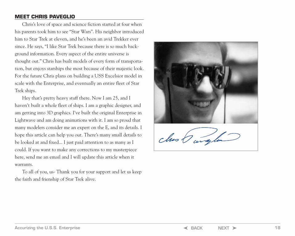
MEET CHRIS PAVEGLIOChris’s love of space and science fiction started at four when
his parents took him to see “Star Wars”. His neighbor introduced
him to Star Trek at eleven, and he’s been an avid Trekker ever
since. He says, “I like Star Trek because there is so much back-
ground information. Every aspect of the entire universe is
thought out.” Chris has built models of every form of transporta-
tion, but enjoys starships the most because of their majestic look.
For the future Chris plans on building a USS Excelsior model in
scale with the Enterprise, and eventually an entire fleet of Star
Trek ships.
Hey that’s pretty heavy stuff there. Now I am 25, and I
haven’t built a whole fleet of ships. I am a graphic designer, and
am getting into 3D graphics. I’ve built the original Enterprise in
Lightwave and am doing animations with it. I am so proud that
many modelers consider me an expert on the E, and its details. I
hope this article can help you out. There’s many small details to
be looked at and fixed... I just paid attention to as many as I
could. If you want to make any corrections to my masterpiece
here, send me an email and I will update this article when it
warrants.
To all of you, us- Thank you for your support and let us keep
the faith and frienship of Star Trek alive.
Accurizing the U.S.S. Enterprise 18BACK NEXT ➤➤

Accurizing the U.S.S. Enterprise 19BACK NEXT ➤➤
STARSHIP U.S.S. ENTERPRISE - UNITED FEDERATION OF PLANETS
NCC-1701
ENTERPRISE
UNITED FEDERATION OF PLANETSSTARSHIP USS ENTERPRISE
UNITED FEDERATION OF PLANETS
NCC-1701-A
Bibliography and Credits:
Star Fleet Assembly Manual, by Paul Matthew Newitt; PMN Designs; Davis, CA, 1983
Mr. Scott’s Guide To The Enterprise, Shane Johnson; Pocket Books, 1987
Original printing of article by FineScale Modeler, Kalmbach Publishing; Waukesha, WI, 1992
“Star Trek” films, Paramount Pictures; Hollywood, CA, 1979-1990
Enterprise Cutaway Poster, David Kimble; 1986
Photos by Chris Paveglio, additional photos by Kalmbach Publishing, illustrations by Chris Paveglio
Thanks to all you who have supported me, inquired about the article, wrote me, posted web-site link, and/or have simply read andlearned from the article. Much thanks to my friend John Nissley, Jr. who introduced me to the universe of Star Trek. Thanks to my9th grade English teacher William Snyder, who gave me encouragement to finish up this article and submit it (despite his initialskeptism that I could be published). I hear he still tells his classes about my article. Thanks to my more than best friend Mandi Rae,for all her support for everything!! Thanks to Steve Jobs and Apple Computer, my favorite computers! Nothing they can’t do for me.Last but not least, Mom and Dad, all your support is greatly appreciated.
Zoom in real close andthe detail is excellent...

Accurizing the U.S.S. Enterprise 20BACK NEXT ➤➤
©2000 Chris Paveglio


![[Verse 1:]€¦ · [Verse 1:] You are holy (you are holy) You are mighty (you are mighty) You are worthy (you are worthy) Worthy of praise (worthy of praise)](https://static.fdocuments.us/doc/165x107/5ad06b877f8b9ad24f8da282/verse-1-verse-1-you-are-holy-you-are-holy-you-are-mighty-you-are-mighty.jpg)