
Connection GT1020/1030 to FR-D700 Inverter¡tor... · 2011-03-11 · Overview Start-up Guide...
16
MITSUBISHI ELECTRIC MITSUBISHI ELECTRIC INDUSTRIAL AUTOMATION GOT1000 GT1020/GT1030 to FR-D700 Inverter Start-up Guide 19 043 2010 Version A
Transcript of Connection GT1020/1030 to FR-D700 Inverter¡tor... · 2011-03-11 · Overview Start-up Guide...

MITSUBISHI ELECTRIC
19 04Versio
GOT1000
GT1020/GT1030 to FR-D700 Inverter
Start-up Guide
MITSUBISHI ELECTRIC INDUSTRIAL AUTOMATION3 2010n A

About this Manual
The texts, illustrations, diagrams and examples in this manual are only intended as aids to helpexplain the functioning, operation, use and programming of the GOT1000 terminals in combi-nation with an FR-D700 Inverter.
If you have any questions regarding the installation and operation of the hardware described inthis manual, please do not hesitate to contact your sales office or one of your Mitsubishi distri-bution partners.
You can also obtain information and answers to frequently asked questions from our Mitsubishiwebsite under www.mitsubishi-automation.com.
No part of this manual may be reproduced, copied, stored in any kind of information retrieval sys-tem or distributed without the prior express written consent of MITSUBISHI ELECTRIC.
MITSUBISHI ELECTRIC reserves the right to change the specifications of its products and/orthe contents of this manual at any time and without prior notice.
© Version A March 2010
Manual References:
Refer to the following manuals for more detailed explanations. For any further questions, pleasecontact your local Mitsubishi Product Provider.
● GOT1000 Series Connection Manual 3/3 (SH(NA)-080532ENG), Sections 37.1 to 37.6
● FR-D700 Inverter Instruction Manual, art. no 226857
bCAUTION:
Do not attempt to install, operate, maintain or inspect the grafical operator terminal orthe inverter until you have read through the correrponding instruction manual care-fully and can use the equipment correctly. Do not use the inverter until you have a fullknowledge of the equipment, safety information and instructions.
bCAUTION:
This Start-up Guide includes a brief summary of the main specifications of theGOT1000 graphic operation terminals and the FR-D700 series of inverters, whichshould be sufficient to enable experienced users to install and configure the units.For further information on the operation terminals and the inverters please refer to theabove mentioned manuals.
Please observe also the safety precautions given in the manuals mentioned above.
GOT1000 I

II
Table of Contents
GOT1
Table of Contents
1 Overview . . . . . . . . . . . . . . . . . . . . . . . . . . . . . . . . . . . . . . . . . . . . . . . . . . . . . . . . . . 1-1
2 Hardware Introduction. . . . . . . . . . . . . . . . . . . . . . . . . . . . . . . . . . . . . . . . . . . . . . . 1-1
3 Cabling . . . . . . . . . . . . . . . . . . . . . . . . . . . . . . . . . . . . . . . . . . . . . . . . . . . . . . . . . . . 1-2
3.1 GOT and Inverter Wiring Diagrams. . . . . . . . . . . . . . . . . . . . . . . . . . . . . . 1-33.2 GOT Terminals . . . . . . . . . . . . . . . . . . . . . . . . . . . . . . . . . . . . . . . . . . . . . . 1-43.3 Programming Cables . . . . . . . . . . . . . . . . . . . . . . . . . . . . . . . . . . . . . . . . . 1-4
4 GT Designer 2 . . . . . . . . . . . . . . . . . . . . . . . . . . . . . . . . . . . . . . . . . . . . . . . . . . . . . 1-5
5 Inverter Settings. . . . . . . . . . . . . . . . . . . . . . . . . . . . . . . . . . . . . . . . . . . . . . . . . . . . 1-7
6 Station Setting . . . . . . . . . . . . . . . . . . . . . . . . . . . . . . . . . . . . . . . . . . . . . . . . . . . . . 1-7
6.1 Indirect Specification . . . . . . . . . . . . . . . . . . . . . . . . . . . . . . . . . . . . . . . . . 1-8
7 Confirm Communication . . . . . . . . . . . . . . . . . . . . . . . . . . . . . . . . . . . . . . . . . . . . . 1-8
000 III


Overview Start-up Guide
1 Overview
This document provides a simple guide to setting up the GT1020 or GT1030 Graphic OperationTerminal (GOT) hardware and firmware for use with an FR-D700 Inverter.
2 Hardware Introduction
The GT1020 and GT1030 are monochrome, 3-color backlight, two communication channelGOT1000 Series touch panel interfaces used for capturing user input to a system.
It should be noted that not all products from the GT1020 or GT1030 range are compatible witha FREQROL inverter connection. Compatible products are identified in the table below.
Model Size Backlight Colors Comm. IF Power
GT1020-LBD 3.7”
160 x 64 dotGreen/Orange/Red
RS422 24 V DC-LBDW White/Pink/Red
GT1030-LBD 4.5”
288 x 96 dotGreen/Orange/Red
-LBDW White/Pink/Red
Tab. 1: Specifications of the operator terminals
For new GT1020 and GT1030 units, included in the box should be the following items:
� (A) GT1020/GT1030� (B) 1 PLC Communication Connector� (C) 1 rubber Panel Mounting Packing� (D) 4 Panel Mounting Brackets
A
B
C
D
GOT1000 1

Start-up Guide Cabling
3 Cabling
Communication
For the GT1020/GT1030 to communicate with the inverter, a communication cable is required.The type of cable used is dependent on the number of inverters used within the system, examp-les of which are illustrated below.
*1 Connect to the PU port of the inverter.
Discription to Fig. 2:
For an explanation of the communication cables please refer to the following section 3.1.
Power
The applicable GT1020/GT1030 GOTs requirean external 24V DC power supply to be connec-ted to the Power Terminal on the back of the GOT.
Fig. 1: One inverter connection
Fig. 2: Multi-drop connection
A B C D
Detailled view
Standard RS422 RS422 RS422 RS422
MeaningBetween inverter
and GOT(to be made by user)
Between distributor and inverter or
between distributors
Terminating resistor Distributor
2

Cabling Start-up Guide
3.1 GOT and Inverter Wiring Diagrams
� The connector figure shows the engagement face.
GOT side(terminal block)
Cable connection and signal direction
Inverter side or discributor side (Modular connector)
Signal name Pin No. Signal name Pin layout*1
SDA 3 RDA
PU port
1 8RJ-45 plug (male)
SDB 6 RDB
RDA 5 SDA
RDB 4 SDB
SG 1 SG
RSA 2 P5S
RSB 7 SG
CSA 8 P5S
CSB
Tab. 2: RS-422 connection between inverter and GOT (Cable type A)
Distributor side(Modular connector)
Cable connection and signal direction
Inverter side or discributor side (Modular connector)
Pin layout� Signal name Pin No. Pin No. Signal
name Pin layout�
PU port
1 8RJ-45 plug (male)
SDA 5 5 SDA
PU port
1 8RJ-45 plug (male)
SDB 4 4 SDB
RDA 3 3 RDA
RDB 6 6 RDB
P5S 2 2 P5S
P5S 8 8 P5S
SG 1 1 SG
Tab. 3: RS-422 connection distributor and inverter (Cable type B)
Distributor side
Cable connection and signal direction
Pin layout� Signal name Pin No.
PU port
1 8RJ-45 plug (male)
SDA 5
Terminating resistor 100 � 1/2WSDB 4
RDA 3
RDB 6
P5S 2
P5S 8
SG 1
Tab. 4: RS-422 connection for mounting a terminating resistor (Cable type C)
GOT1000 3

Start-up Guide Cabling
3.2 GOT Terminals
The GT1020/GT1030 is fitted with screw terminals, use a small flathead screwdriver to securethe wires within the PLC Communication Connector.
3.3 Programming Cables
The GT1020 and GT1030 come pre-installed with an OS and FX communication driver, but wit-hout any project data. To download a project from a PC running GT Designer2 to the GOT, a pro-gramming cable is required that connects to the RS-232C 6-pin Mini-DIN port on the back of theGOT. It is recommended to use a shielded USB A-type to Mini-B type cable with a ferrite corepaired with the GT10-RS2TUSB-5S, but any RS-232C programming cable for the Q-Series willalso work fine. A diagram of both is shown below.
Fig. 3: Terminal points in detail
Fig. 4: Connection diagram
NOTE Note that using the GT10-RS2TUSB-5S will require a virtual USB COM port driver to beinstalled on the PC. The COM port number can be automatically or manually assigned sothat it does not overlap with the existing COM port numbers assigned on that PC. Whenusing a Q-Series programming cable, the COM port number already assigned to the RS-232C interface of the PC will have to be checked.
USB + GT10-RS2TUSB-5S
QC30R2 (RS-232C)
PC
or GOT
4
GT Designer 2 Start-up Guide
4 GT Designer 2
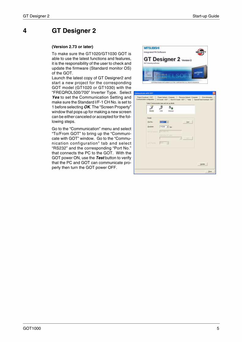
(Version 2.73 or later)
To make sure the GT1020/GT1030 GOT isable to use the latest functions and features,it is the responsibility of the user to check andupdate the firmware (Standard monitor OS)of the GOT.Launch the latest copy of GT Designer2 andstart a new project for the correspondingGOT model (GT1020 or GT1030) with the“FREQROL500/700” Inverter Type. SelectYes to set the Communication Setting andmake sure the Standard I/F-1 CH No. is set to1 before selecting OK. The “Screen Property”window that pops up for making a new screencan be either canceled or accepted for the fol-lowing steps.
Go to the “Communication” menu and select“To/From GOT” to bring up the “Communi-cate with GOT” window. Go to the “Commu-nication configuration” tab and select“RS232” and the corresponding “Port No.”that connects the PC to the GOT. With theGOT power ON, use the Test button to verifythat the PC and GOT can communicate pro-perly then turn the GOT power OFF.
GOT1000 5
Start-up Guide GT Designer 2
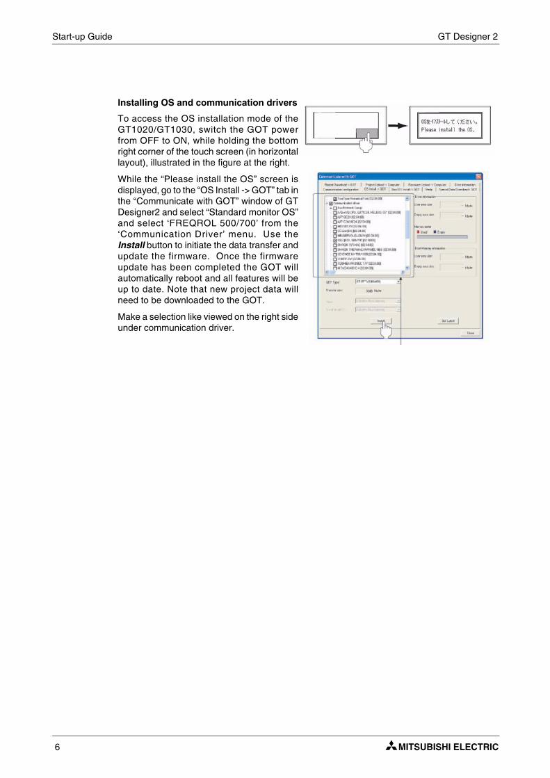
Installing OS and communication drivers
To access the OS installation mode of theGT1020/GT1030, switch the GOT powerfrom OFF to ON, while holding the bottomright corner of the touch screen (in horizontallayout), illustrated in the figure at the right.
While the “Please install the OS” screen isdisplayed, go to the “OS Install -> GOT” tab inthe “Communicate with GOT” window of GTDesigner2 and select “Standard monitor OS”and select ‘FREQROL 500/700’ from the‘Communication Driver’ menu. Use theInstall button to initiate the data transfer andupdate the firmware. Once the firmwareupdate has been completed the GOT willautomatically reboot and all features will beup to date. Note that new project data willneed to be downloaded to the GOT.
Make a selection like viewed on the right sideunder communication driver.
6
Inverter Settings Start-up Guide
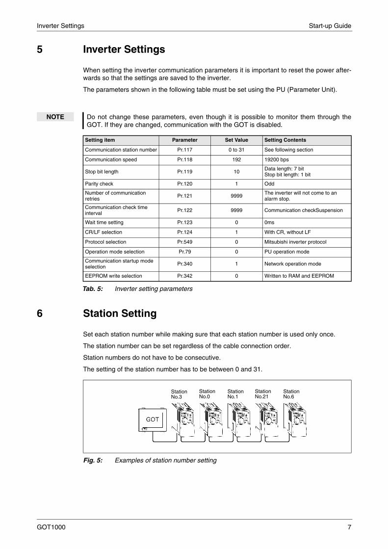
5 Inverter Settings
When setting the inverter communication parameters it is important to reset the power after-wards so that the settings are saved to the inverter.
The parameters shown in the following table must be set using the PU (Parameter Unit).
6 Station Setting
Set each station number while making sure that each station number is used only once.
The station number can be set regardless of the cable connection order.
Station numbers do not have to be consecutive.
The setting of the station number has to be between 0 and 31.
NOTE Do not change these parameters, even though it is possible to monitor them through theGOT. If they are changed, communication with the GOT is disabled.
Setting item Parameter Set Value Setting Contents
Communication station number Pr.117 0 to 31 See following section
Communication speed Pr.118 192 19200 bps
Stop bit length Pr.119 10 Data length: 7 bitStop bit length: 1 bit
Parity check Pr.120 1 Odd
Number of communication retries Pr.121 9999 The inverter will not come to an
alarm stop.
Communication check time interval Pr.122 9999 Communication checkSuspension
Wait time setting Pr.123 0 0ms
CR/LF selection Pr.124 1 With CR, without LF
Protocol selection Pr.549 0 Mitsubishi inverter protocol
Operation mode selection Pr.79 0 PU operation mode
Communication startup mode selection Pr.340 1 Network operation mode
EEPROM write selection Pr.342 0 Written to RAM and EEPROM
Tab. 5: Inverter setting parameters
Fig. 5: Examples of station number setting
StationNo.3
StationNo.0
StationNo.1
StationNo.21
StationNo.6
GOT1000 7

Start-up Guide Confirm Communication
6.1 Indirect Specification
When setting the station number indirectly, the station number of the inverter can be changedusing the 16-bit GOT internal data register (GD10 to GD25). When specifying the station num-ber from 100 to 155 on GT Designer 2, the value within GD10 to GD25 is equal to the station no.
Tab. 6: Secification of the station number
7 Confirm Communication
The communication monitoring is a function that checks whether the GOT can communicatewith the Inverter. If no error is shown, communication has been set up correctly.
Specification station no. Compatible Device Setting range
100 GD10
0 to 31If the associated device contains a value outside this range an error (dedicated device is out of range) will occur.
101 GD11
102 GD12
103 GD13
104 GD14
105 GD15
106 GD16
107 GD17
108 GD18
109 GD19
110 GD20
111 GD21
112 GD22
113 GD23
114 GD24
115 GD25
8


MIGeGoD-PhFaxMICzeAvCZPhFaxMIFre25F-9PhFaxMIIrisWeIRPhFaxMIItaViaI-2PhFaxMIPoKraPLPhFaxMISpCaE-0PhFaxMIUKTraUKPhFaxMIOff8-1ToPhFaxMI50VePhFax
N
L
N
A
FAC
MITSUBISHI ELECTRIC
HEADQUARTERS
EUROPETSUBISHI ELECTRIC EUROPE B.V.rman Branchthaer Straße 840880 Ratingenone: +49 (0)2102 / 486-0: +49 (0)2102 / 486-1120
CZECH REPUBLICTSUBISHI ELECTRIC EUROPE B.V.ch Branch
enir Business Park, Radlická 714/113a-158 00 Praha 5one: +420 - 251 551 470: +420 - 251-551-471
FRANCETSUBISHI ELECTRIC EUROPE B.V.nch Branch
, Boulevard des Bouvets2741 Nanterre Cedex
one: +33 (0)1 / 55 68 55 68: +33 (0)1 / 55 68 57 57
IRELANDTSUBISHI ELECTRIC EUROPE B.V.h Branchstgate Business Park, Ballymount
L-Dublin 24one: +353 (0)1 4198800: +353 (0)1 4198890
ITALYTSUBISHI ELECTRIC EUROPE B.V.lian Branchle Colleoni 70041 Agrate Brianza (MB)one: +39 039 / 60 53 1: +39 039 / 60 53 312
POLANDTSUBISHI ELECTRIC EUROPE B.V.land Branchkowska 50
-32-083 Baliceone: +48 (0)12 / 630 47 00: +48 (0)12 / 630 47 01
SPAINTSUBISHI ELECTRIC EUROPE B.V.anish Branchrretera de Rubí 76-80
8190 Sant Cugat del Vallés (Barcelona)one: 902 131121 // +34 935653131: +34 935891579
UKTSUBISHI ELECTRIC EUROPE B.V. Branchvellers Lane-Hatfield, Herts. AL10 8XBone: +44 (0)1707 / 27 61 00: +44 (0)1707 / 27 86 95
JAPANTSUBISHI ELECTRIC CORPORATIONice Tower “Z” 14 F2,1 chome, Harumi Chuo-Ku
kyo 104-6212one: +81 3 622 160 60: +81 3 622 160 75
USATSUBISHI ELECTRIC AUTOMATION, Inc.0 Corporate Woods Parkwayrnon Hills, IL 60061one: +1 847 478 21 00: +1 847 478 22 53
EUROPEAN REPRESENTATIVES
AUSTRIAGEVAWiener Straße 89AT-2500 BadenPhone: +43 (0)2252 / 85 55 20Fax: +43 (0)2252 / 488 60
BELARUSTEHNIKONOktyabrskaya 16/5, Off. 703-711BY-220030 MinskPhone: +375 (0)17 / 210 46 26Fax: +375 (0)17 / 210 46 26
BELGIUMESCO DRIVES & AUTOMATIONCulliganlaan 3BE-1831 DiegemPhone: +32 (0)2 / 717 64 30Fax: +32 (0)2 / 717 64 31
BELGIUMKoning & Hartman b.v.Woluwelaan 31BE-1800 VilvoordePhone: +32 (0)2 / 257 02 40Fax: +32 (0)2 / 257 02 49
BOSNIA AND HERZEGOVINAINEA BH d.o.o.Aleja Lipa 56BA-71000 SarajevoPhone: +387 (0)33 / 921 164Fax: +387 (0)33/ 524 539
BULGARIAAKHNATON4 Andrej Ljapchev Blvd. Pb 21BG-1756 SofiaPhone: +359 (0)2 / 817 6004Fax: +359 (0)2 / 97 44 06 1
CROATIAINEA CR d.o.o.Losinjska 4 aHR-10000 ZagrebPhone: +385 (0)1 / 36 940 - 01/ -02/ -03Fax: +385 (0)1 / 36 940 - 03
CZECH REPUBLICAutoCont C.S. s.r.o.Technologická 374/6CZ-708 00 Ostrava-PustkovecPhone: +420 595 691 150Fax: +420 595 691 199
CZECH REPUBLICB:ELECTRIC, s.r.o.Mladoboleslavská 812CZ-197 00 Praha 19 - KbelyPhone: +420 286 850 848, +420 724 317 975Fax: +420 286 850 850
DENMARKBeijer Electronics A/SLykkegårdsvej 17, 1.DK-4000 RoskildePhone: +45 (0)46/ 75 76 66Fax: +45 (0)46 / 75 56 26
ESTONIABeijer Electronics Eesti OÜPärnu mnt.160iEE-11317 TallinnPhone: +372 (0)6 / 51 81 40Fax: +372 (0)6 / 51 81 49
FINLANDBeijer Electronics OYJaakonkatu 2FIN-01620 VantaaPhone: +358 (0)207 / 463 500Fax: +358 (0)207 / 463 501
GREECEUTECO A.B.E.E.5, Mavrogenous Str.GR-18542 PiraeusPhone: +30 211 / 1206 900Fax: +30 211 / 1206 999
HUNGARYMELTRADE Ltd.Fertő utca 14.HU-1107 BudapestPhone: +36 (0)1 / 431-9726Fax: +36 (0)1 / 431-9727
LATVIABeijer Electronics SIAVestienas iela 2LV-1035 RigaPhone: +371 (0)784 / 2280Fax: +371 (0)784 / 2281
LITHUANIABeijer Electronics UABSavanoriu Pr. 187LT-02300 VilniusPhone: +370 (0)5 / 232 3101Fax: +370 (0)5 / 232 2980
EUROPEAN REPRESENTATIVES
MALTAALFATRADE Ltd.99, Paola HillMalta- Paola PLA 1702Phone: +356 (0)21 / 697 816Fax: +356 (0)21 / 697 817
MOLDOVAINTEHSIS srlbld. Traian 23/1MD-2060 KishinevPhone: +373 (0)22 / 66 4242Fax: +373 (0)22 / 66 4280
NETHERLANDSHIFLEX AUTOM.TECHNIEK B.V.Wolweverstraat 22NL-2984 CD RidderkerkPhone: +31 (0)180 – 46 60 04Fax: +31 (0)180 – 44 23 55
NETHERLANDSKoning & Hartman b.v.Haarlerbergweg 21-23NL-1101 CH AmsterdamPhone: +31 (0)20 / 587 76 00Fax: +31 (0)20 / 587 76 05
NORWAYBeijer Electronics ASPostboks 487NO-3002 DrammenPhone: +47 (0)32 / 24 30 00Fax: +47 (0)32 / 84 85 77
ROMANIASirius Trading & Services srlAleea Lacul Morii Nr. 3RO-060841 Bucuresti, Sector 6Phone: +40 (0)21 / 430 40 06Fax: +40 (0)21 / 430 40 02
SERBIACraft Con. & Engineering d.o.o.Bulevar Svetog Cara Konstantina 80-86SER-18106 NisPhone: +381 (0)18 / 292-24-4/5Fax: +381 (0)18 / 292-24-4/5
SERBIAINEA SR d.o.o.Izletnicka 10SER-113000 SmederevoPhone: +381 (0)26 / 617 163Fax: +381 (0)26 / 617 163
SLOVAKIAAutoCont Control s.r.o.Radlinského 47SK-02601 Dolny KubinPhone: +421 (0)43 / 5868210Fax: +421 (0)43 / 5868210
SLOVAKIACS MTrade Slovensko, s.r.o.Vajanskeho 58SK-92101 PiestanyPhone: +421 (0)33 / 7742 760Fax: +421 (0)33 / 7735 144
SLOVENIAINEA d.o.o.Stegne 11SI-1000 LjubljanaPhone: +386 (0)1 / 513 8100Fax: +386 (0)1 / 513 8170
SWEDENBeijer Electronics ABBox 426SE-20124 MalmöPhone: +46 (0)40 / 35 86 00Fax: +46 (0)40 / 35 86 02
SWITZERLANDOmni Ray AGIm Schörli 5CH-8600 DübendorfPhone: +41 (0)44 / 802 28 80Fax: +41 (0)44 / 802 28 28
TURKEYGTSBayraktar Bulvari Nutuk Sok. No:5TR-34775 Yukari Dudullu-Umraniye-ISTANBULPhone: +90 (0)216 526 39 90Fax: +90 (0)216 526 3995
UKRAINECSC Automation Ltd.4-B, M. Raskovoyi St.UA-02660 KievPhone: +380 (0)44 / 494 33 55Fax: +380 (0)44 / 494-33-66
EURASIAN REPRESENTATIVES
KAZAKHSTAKazpromautomatics Ltd.Mustafina Str. 7/2KAZ-470046 KaragandaPhone: +7 7212 / 50 11 50Fax: +7 7212 / 50 11 50
MIDDLE EAST REPRESENTATIVES
ISRAEILAN & GAVISH Ltd.24 Shenkar St., Kiryat ArieIL-49001 Petah-TiqvaPhone: +972 (0)3 / 922 18 24Fax: +972 (0)3 / 924 0761
LEBANOCEG INTERNATIONALCebaco Center/Block A Autostrade DORALebanon - BeirutPhone: +961 (0)1 / 240 430Fax: +961 (0)1 / 240 438
AFRICAN REPRESENTATIVE
SOUTH AFRICCBI Ltd.Private Bag 2016ZA-1600 IsandoPhone: + 27 (0)11 / 977 0770Fax: + 27 (0)11 / 977 0761
MITSUBISHIELECTRIC
TORY AUTOMATIONMitsubishi Electric Europe B.V. /// FA - European Business Group /// Gothaer Straße 8 /// D-40880 Ratingen /// GermanyTel.: +49(0)2102-4860 /// Fax: +49(0)2102-4861120 /// [email protected] /// www.mitsubishi-automation.com