Configuration Optimization of Clamping …¬guration Optimization of Clamping Members of...
23
Configuration Optimization of Clamping Members of Frame-Supported Membrane Structures M. Ohsaki a,∗ , T. Nakajima b , J. Fujiwara c , F. Takeda c a Dept. of Architecture, Hiroshima University, Japan b Dept. of Architecture and Architectural Engineering, Kyoto University, Japan c Technical Research Center, Taiyo Kogyo Corporation, Japan Abstract A method is presented for configuration optimization of frames that have specified properties on nodal displacements, stresses, and reaction forces against static loads. The conventional ground structure approach is first used for topology optimization. A feasible solution with small number of members satisfying all the design requirements except the stress constraints is obtained by assigning artificially small upper-bound displacement, or by penalizing the stiffness of a thin member. This way, the well-known difficulty in topology optimization under stress constraints is successfully avoided. The nodal loca- tions and cross-sectional areas of the feasible solution are next optimized to obtain an approximate optimal configuration under stress constraints. The proposed method is applied to design of self-fastening clamping members for membrane structures modeled using frame elements. An optimization result is also presented for a clamping member that adjusts deformation of membrane by applying a clamping force with a vertically attached bolt. Keywords: Membrane structure, Clamping member, Configuration optimization, Stress constraints 1. Introduction Shape and topology optimization of continuum structures is a rather ma- tured field of research [1–3], and there are many applications in various fields ∗ 1-4-1, Kagamiyama, Higashi-Hiroshima 739-8527, Dept. of Architecture, Hiroshima University, Japan Email address: [email protected] (M. Ohsaki) Preprint submitted to Engineering Structures July 19, 2011
Transcript of Configuration Optimization of Clamping …¬guration Optimization of Clamping Members of...

Configuration Optimization of Clamping Members of
Frame-Supported Membrane Structures
M. Ohsakia,∗, T. Nakajimab, J. Fujiwarac, F. Takedac
aDept. of Architecture, Hiroshima University, JapanbDept. of Architecture and Architectural Engineering, Kyoto University, Japan
cTechnical Research Center, Taiyo Kogyo Corporation, Japan
Abstract
A method is presented for configuration optimization of frames that havespecified properties on nodal displacements, stresses, and reaction forcesagainst static loads. The conventional ground structure approach is first usedfor topology optimization. A feasible solution with small number of memberssatisfying all the design requirements except the stress constraints is obtainedby assigning artificially small upper-bound displacement, or by penalizing thestiffness of a thin member. This way, the well-known difficulty in topologyoptimization under stress constraints is successfully avoided. The nodal loca-tions and cross-sectional areas of the feasible solution are next optimized toobtain an approximate optimal configuration under stress constraints. Theproposed method is applied to design of self-fastening clamping membersfor membrane structures modeled using frame elements. An optimizationresult is also presented for a clamping member that adjusts deformation ofmembrane by applying a clamping force with a vertically attached bolt.
Keywords: Membrane structure, Clamping member, Configurationoptimization, Stress constraints
1. Introduction
Shape and topology optimization of continuum structures is a rather ma-tured field of research [1–3], and there are many applications in various fields
∗1-4-1, Kagamiyama, Higashi-Hiroshima 739-8527, Dept. of Architecture, HiroshimaUniversity, Japan
Email address: [email protected] (M. Ohsaki)
Preprint submitted to Engineering Structures July 19, 2011

of engineering including civil and architectural engineering [4–6]. The firstauthor presented a method of optimizing shapes of beam flanges for maximiz-ing the plastic energy dissipation under static deformation [7, 8]. This way,it is possible to optimize performances of mass-produced parts of buildingstructures. However, topology optimization of continuum under stress con-straints is still difficult, because of the design dependency of the optimizationproblem [9].
There are also many researches on simultaneous optimization of shape andtopology, which is called configuration optimization, of trusses and frames [10–13]. Optimal topologies of trusses under constraints on global propertiessuch as compliance and displacements can be easily obtained using the stan-dard ground structure approach, where unnecessary members are removedthrough optimization from a highly-connected ground structure. However,even for trusses, there still exist several difficulties in problems under stressconstraints [14–16], which are categorized as local constraints [17] that leadto existence of many thin members or elements; i.e., the number of memberscannot be reduced effectively by simple application of the ground structureapproach. In the most widely used SIMP (solid isotropic microstructurewith penalty or solid isotropic material with penalization) approach [1, 18]to topology optimization of continua, an intermediate value of material den-sity is penalized by assigning artificially small stiffness. Kim et. al [19]penalized the stiffnesses of the joints to obtain simple optimal topologies offrames. Takezawa et al. [20] formulated a frame optimization problem usinga penalization parameter; however, they did not penalize the stiffness in thenumerical examples. Therefore, to the authors’ knowledge, there is no studyon direct application of SIMP approach to topology optimization of frames.
Membrane structures are widely used for stadiums and arenas coveringlarge space with lightweight membrane material [21, 22]. Membrane struc-tures are generally connected to the boundary frames with clamping membersas illustrated in Fig. 1. Since such devices are mass-products and have largeportion of the total weight of the membrane structure, the total productioncost can be reduced by optimizing the cross-sectional shapes of members.Furthermore, when external loads such as wind loads are applied to the mem-brane, its tensile force increases and the membrane sheet may detach fromthe clamping member prior to the fracture of membrane material. Therefore,the load resistance capacity of the membrane structure can be improved byoptimizing the clamping members so that the clamping force increases as aresult of increase of the tensile force of membrane.
2

Clamping member
Bolt
Boundary frame
Bolt holes
Membrane sheetTensile force
Endrope
Figure 1: Illustration of a clamping member of a frame-supported membrane structure.
A structure that realizes the specified function utilizing its flexibility iscalled a compliant mechanism, which can be generated using structural op-timization techniques [23–25]. However, those techniques cannot be directlyapplied to practical problems, because stress constraints should be satisfiedby real-world structures.
In this paper, we first present a method for configuration optimization ofgeneral frames that have specified properties on nodal displacements, stresses,and reaction forces against static loads. We consider only static loads, be-cause the regulations for design of structural parts in civil and architecturalengineering are based on responses against static design loads. The groundstructure approach is first used for topology optimization. A feasible solu-tion with small number of members satisfying design requirements exceptthe stress constraints is obtained by assigning artificially small upper-bounddisplacement, or by penalizing the stiffness of a thin member. The nodallocations and cross-sectional areas are next optimized for the feasible solu-tion to obtain an approximate optimal configuration under stress constraints.This way, the well-known difficulty in topology optimization under stress con-straints is successfully avoided.
The proposed method is applied to design of clamping members of frame-supported membrane structures. The clamping process of a membrane isillustrated in Fig. 2. In this process, temporary supports are attached firstto the boundary frame of the structure along the boundary of the mem-brane sheet. To obtain reaction force from the boundary frame through
3

Bolt
Temporary support
Membrane sheet
Boundary frame
Clamping member
Tensioning by tool
Figure 2: Construction process of a frame-supported membrane structure.
the temporary support, the membrane is pulled (tensioned) by using a tooluntil the preassigned holes of the membrane are located on the bolt holesof the boundary frame; then, the membrane is pressed to the frame usingthe clamping member and bolts. However, in this process, there exist thefollowing difficulties:
1. Adjustment of tensile force of membrane is very difficult, because theholes are preassigned in the factory.
2. Temporary supports for obtaining reaction force through tensioningtools are needed in addition to the boundary frame.
In this paper, an optimization approach is presented to overcome thesedifficulties. The section of the clamping member is modeled as a framethat undergoes small elastic deformation. The objective function is the totalstructural volume, which is to be minimized, and the constraint is given forthe clamping force against the membrane to obtain a self-fastening member.We also present an optimization result of a clamping member that enablesus to adjust deformation of membrane by applying a clamping force througha vertically attached bolt.
2. Topology optimization of a self-fastening clamping member
2.1. Problem formulation
Simultaneous optimization of topology, cross-sectional areas of members,and nodal locations, which is simply called configuration optimization, is
4

carried out for a frame subjected to static loads. A two-step procedure ispresented below to overcome difficulties in topology optimization under stressconstraints.
The standard ground structure approach is used at the first step; i.e.,unnecessary nodes and members are removed through optimization from thehighly connected initial ground structure to obtain a frame with small num-ber of members. The design variables are the cross-sectional areas A =(A1, . . . , Am) of members, where m is the number of members in the groundstructure. The cross-sectional properties such as the second moment of iner-tia and the section modulus are assumed to be functions of the cross-sectionalarea.
A constraint is given so that the maximum absolute value |σi(A)| amongthe normal stresses of the ith member, evaluated at the two edges of twoends, does not exceed the specified upper bound σU. A lower bound RL isalso given for the reaction force R(A) at the specified direction of a support.Then, the optimization problem for minimizing the total structural volumeV (A) is formulated as
P1 : minimize V (A) (1a)
subject to |σi(A)| ≤ σU, (i = 1, ...,m) (1b)
R(A) ≥ RL (1c)
AL ≤ A ≤ AU (1d)
where AL = (AL1 , . . . , AL
m) and AU = (AU1 , . . . , AU
m) are the lower and up-per bounds for A, respectively. Note that a small positive value is givenfor the lower-bound cross-sectional area to prevent instability of the frameduring optimization process, and the member with Ai = AL
i is removed afteroptimization.
An optimal topology satisfying constraints on stresses and a reactionforce may be found by solving Problem P1, which is a standard nonlinearprogramming (NLP) problem. There exists a discontinuity in the gradient ofthe maximum stress in (1b), which can be avoided by assigning the upper-and lower-bound constraints for four edge-stresses of all members. However,we use the formulation (1b), because an optimal solution can be successfullyfound, as demonstrated in the numerical examples, using a gradient-basedNLP algorithm with line search and a forward finite difference approach forevaluation of gradients. Note that the location and sign of maximum ab-solute value of stress in each member does not vary at the stage when the
5

optimization process converges; therefore, there is no difficulty for applica-tion of a finite-difference approach for gradient evaluation of the maximumabsolute value of stress. Thus, the number of stress constraints is m, while itis 8m if upper and lower bounds are given for the four edge-stresses in eachmember.
It is well known in truss topology optimization that the number of mem-bers cannot be successfully reduced by using a conventional ground structureapproach with an NLP algorithm, if stress constraints are considered [15, 16].Therefore, we first carry out optimization, as follows, with a displacementconstraint and without stress constraints:
P2 : minimize V (A) (2a)
subject to |U(A)| ≤ UU (2b)
R(A) ≥ RL (2c)
AL ≤ A ≤ AU (2d)
where UU is the upper bound for the absolute value of a specified displace-ment component U(A). Problem P2 is first solved to obtain a topology witha small number of members. Then, Problem P1 is solved starting from theoptimal solution of Problem P2 to obtain an approximate optimal topologyunder constraints on stresses and a reaction force.
In the numerical examples, the width of the section of each member isfixed, because the frame model represents a section of a clamping member;hence, the height is proportional to the cross-sectional area. Since the bend-ing stiffness K is proportional to h3 with a coefficient c as K = ch3 for thesolid rectangular section with the height h and constant width, the materialis more efficiently used by a thick member than a thin member. In contrast,the axial stiffness is proportional to the height of the section. When thedisplacement bound becomes smaller, the members have larger heights andbending stiffness dominates over the axial stiffness. Consequently, a topologywith small number of members can be obtained by assigning an artificiallysmall upper-bound displacement.
Existence of thin members can also be avoided in a similar manner asSIMP approach for continuum topology optimization. Let p (≥ 1) denotea penalization parameter. An appropriately large value, e.g., the maximumvalue of Ai among all members in the optimal solution of Problem P2 withmoderately large UU, is denoted by Amax. Then, the cross-sectional area Ai
6

is converted to a penalized value APi using p as
APi = AL
i + (Amax − ALi )
(Ai − AL
i
Amax − ALi
)p
(3)
For example, APi = Ai if p = 1. In contrast, AP
i = ALi + (Amax
i − ALi )/4 if
(Ai −ALi )/(Amax
i −ALi ) = 1/2 and p = 2; i.e., in this case, the cross-sectional
area is reduced by half if ALi is sufficiently small. Then, the optimization
problem is formulated as
P3 : minimize V (A) (4a)
subject to |U(AP)| ≤ UU (4b)
R(AP) ≥ RL (4c)
AL ≤ A ≤ AU (4d)
where AP = (AP1 , . . . , AP
m). Note that the total structural volume is com-puted using A, and the displacement and reaction force are computed usingAP. Therefore, U(AP) and R(AP) do not represent any physical values,because they are functions of the penalized cross-sectional areas.
It is seen from (3) that the stiffness of a member is artificially increasedif Ai is larger than Amax. Furthermore, convergence property of the NLPalgorithm is deteriorated if too large value is given for p. It is shown in thefollowing numerical examples that the parameter value between 1.5 and 2.0can reach a good topology with small number of members without sacrificingconvergence property.
Finally, the nodal locations as well as the cross-sectional areas are opti-mized to obtain the optimal configuration under constraints on stresses anda reaction force. The optimal solution of Problem P2 or P3 can be used asthe ground structure with reduced number of members. Consequently, Aand m denote the cross-sectional areas and the number of members of theground structure with a reduced size. Let X denote the vector consisting ofthe variable components of the nodal coordinates. Then, the optimization
7
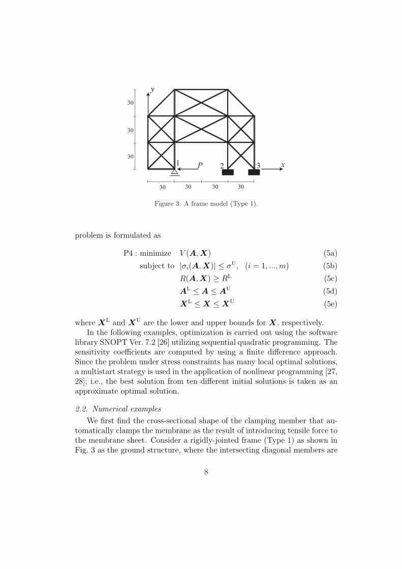
12 3P x
y
30 303030
30
30
30
Figure 3: A frame model (Type 1).
problem is formulated as
P4 : minimize V (A, X) (5a)
subject to |σi(A, X)| ≤ σU, (i = 1, ...,m) (5b)
R(A, X) ≥ RL (5c)
AL ≤ A ≤ AU (5d)
XL ≤ X ≤ XU (5e)
where XL and XU are the lower and upper bounds for X, respectively.In the following examples, optimization is carried out using the software
library SNOPT Ver. 7.2 [26] utilizing sequential quadratic programming. Thesensitivity coefficients are computed by using a finite difference approach.Since the problem under stress constraints has many local optimal solutions,a multistart strategy is used in the application of nonlinear programming [27,28]; i.e., the best solution from ten different initial solutions is taken as anapproximate optimal solution.
2.2. Numerical examples
We first find the cross-sectional shape of the clamping member that au-tomatically clamps the membrane as the result of introducing tensile force tothe membrane sheet. Consider a rigidly-jointed frame (Type 1) as shown inFig. 3 as the ground structure, where the intersecting diagonal members are
8

Figure 4: Optimal configuration of Type 1 for Problem P1 with stress constraints.
connected at the centers. The frame is supported with roller at support 1 andfixed at supports 2 and 3. The member is supposed to have solid rectangularsection with the fixed width b = 10 mm. A load P = 500 N is applied inthe negative x-direction at support 1. The reaction force R represents thevertical (positive y-directional) force at support 1; i.e., the device clamps themembrane if R is positive.
The elastic modulus of the members is 2.0×10⁵ N/mm2. The lower boundRL for reaction force is 200 N, and the upper-bound stress σU is 200 N/mm2.The cross-sectional areas of all 42 members are independent variables withlower bound AL
i = 0.1 mm2, whereas different values of AUi are used for
the optimization problems below. In the following, the units of length andforce are mm and N, respectively. A uniform random number 0 ≤ ri < 1 isgenerated to obtain the initial value of Ai as 50ri + 1.0.
Problem P1 is solved with the upper-bound cross-sectional area AUi = 200;
i.e., the upper-bound of height is 200/10 = 20. The optimization result afterremoving the members with Ai = AL
i is shown in Fig. 4, where the height ofeach member is drawn with real scale. Note that the reaction constraint isactive as R = RL = 200, and the objective function value is V = 1.1018×10⁴.If all cross-sectional areas have the same value 100, then R = −141.11; i.e.,the device should be pulled downward by the membrane sheet at support1, which is not realistic; therefore, the direction of reaction force has beensuccessfully reversed through optimization.
As is seen from Fig. 4, the number of members is not drastically reduced,because stress constraints should be satisfied in all members including verythin members. Therefore, Problem P2 is solved to obtain a topology with
9

(a) (b)
(c) (d)
Figure 5: Optimal topology of Type 1 for Problem P2 with various values of UU; (a)UU = 0.01, (b) UU = 0.02, (c) UU = 0.04, (d) UU = 0.1.
smaller number of members from the initial ground structure in Fig. 3. Alarge upper bound AU = 1000 is given to allow the existence of very thickmembers. The upper bound UU = 0.1 is given for the absolute value of thehorizontal displacement of support 1.
The optimal topology is shown in Fig. 5(d), where the height of eachmember is scaled by 1/5. The optimal objective value is V = 1.6781 × 10⁴.As is seen from Fig. 5(d), there still exist many members that seem to beunnecessary. Therefore, we assign smaller upper-bound displacement to allowlarger structural volume and cross-sectional areas. The optimal solution forUU = 0.01 is shown in Fig. 5(a), where V = 6.7593 × 10⁴ and the height ofeach member is scaled by 1/5. The solutions for UU = 0.02 and 0.04 are alsoshown in Figs. 5(b) and (c), respectively. We can confirm from Figs. 5(a)–(d)that the number of members decreases and the heights of existing membersincrease as the displacement constraint becomes tight.
The total structural volume V and number of members nopt of optimaltopology for various values of UU are listed in Table 1. We can confirm thata solution with smaller nopt and larger V is obtained as UU is decreased.
10

Table 1: Total structural volume V and number of members nopt of optimal topologies ofType 1 for Problem P2 with various values of UU.
UU V (×104) nopt
0.1 1.6782 300.09 1.8513 300.08 2.3396 270.07 2.3516 300.06 2.7289 300.05 3.2310 280.04 3.8090 280.03 4.6826 290.02 5.0352 120.01 6.7593 7
However, the maximum height of the members in Fig. 5(a) for UU = 0.01is 56.439, which is unrealistic in comparison to the dimension of the frame.Furthermore, stress constraints should be satisfied for practical application.Hence, the displacement bound is conceived as an artificial parameter for con-trolling the number of members in a frame that satisfies design requirementsexcept the stress constraints.
Optimal solutions are also found for Problem P3 with various values ofthe penalization parameter p. The displacement bound is UU = 0.1, and themaximum cross-sectional area 49.226 of the optimal solution in Fig. 5(d) isassigned for Amax. Figs. 6(a)–(d) show the solutions for p = 1.4, 1.5, 1.7, and2.0, respectively, where the height of each member is scaled by 1/5. The totalstructural volume V and number of members nopt of optimal topologies forvarious values of p are listed in Table 2. As is seen from Figs. 6(a)–(d) andTable 2, a solution with smaller number of members is obtained by increasingp. However, there is no correlation between p and V , because the stiffness isartificially increased for a member with Ai > Amax, while it is decreased forAi < Amax.
We next solve Problem P4 using the solution in Fig. 5(a) as the ini-tial ground structure with reduced number of members. Each member inFig. 5(a) is divided into shorter members to obtain a smoothly curved frame.The vertical coordinates of nodes except the supports are also considered
11

(a) (b)
(c) (d)
Figure 6: Optimal topologies of Type 1 for Problem P3 with various values of p; (a)p = 1.4, (b) p = 1.5, (c) p = 1.7, (d) p = 2.0.
Figure 7: Optimal solution of Type 1 for Problem P4 with stress constraints with variablenodal locations.
as design variables. Let Y 0i denote the y-coordinate of the ith node of the
initial frame obtained by sub-division of the frame in Fig. 5(a). The upperand lower bounds for Yi are given as Y 0
i + 5 and Y 0i − 5, respectively. Note
that rather strict bounds are given to avoid an optimal shape with smallheight, because the endrope for the membrane sheet should be contained inthe clamping member.
Fig. 7 shows the optimal shape with real scale, where V = 1.7082 ×10⁴. Fig. 8 shows the deformed shape with magnification factor 20 for thenodal displacement. As is seen, only the nodes near support 1 move inthe horizontal direction; thus, a vertical compressive force is applied fromthe frame to the support, and, accordingly, the clamping force increases as
12
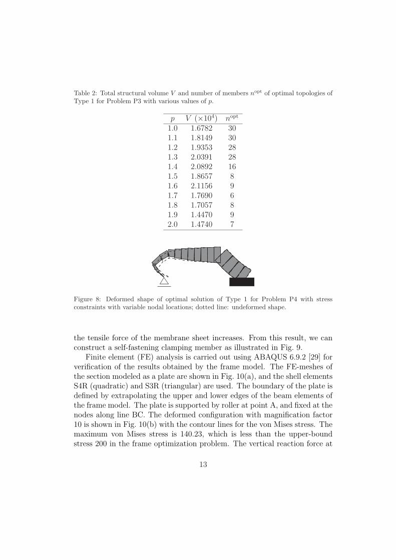
Table 2: Total structural volume V and number of members nopt of optimal topologies ofType 1 for Problem P3 with various values of p.
p V (×104) nopt
1.0 1.6782 301.1 1.8149 301.2 1.9353 281.3 2.0391 281.4 2.0892 161.5 1.8657 81.6 2.1156 91.7 1.7690 61.8 1.7057 81.9 1.4470 92.0 1.4740 7
Figure 8: Deformed shape of optimal solution of Type 1 for Problem P4 with stressconstraints with variable nodal locations; dotted line: undeformed shape.
the tensile force of the membrane sheet increases. From this result, we canconstruct a self-fastening clamping member as illustrated in Fig. 9.
Finite element (FE) analysis is carried out using ABAQUS 6.9.2 [29] forverification of the results obtained by the frame model. The FE-meshes ofthe section modeled as a plate are shown in Fig. 10(a), and the shell elementsS4R (quadratic) and S3R (triangular) are used. The boundary of the plate isdefined by extrapolating the upper and lower edges of the beam elements ofthe frame model. The plate is supported by roller at point A, and fixed at thenodes along line BC. The deformed configuration with magnification factor10 is shown in Fig. 10(b) with the contour lines for the von Mises stress. Themaximum von Mises stress is 140.23, which is less than the upper-boundstress 200 in the frame optimization problem. The vertical reaction force at
13
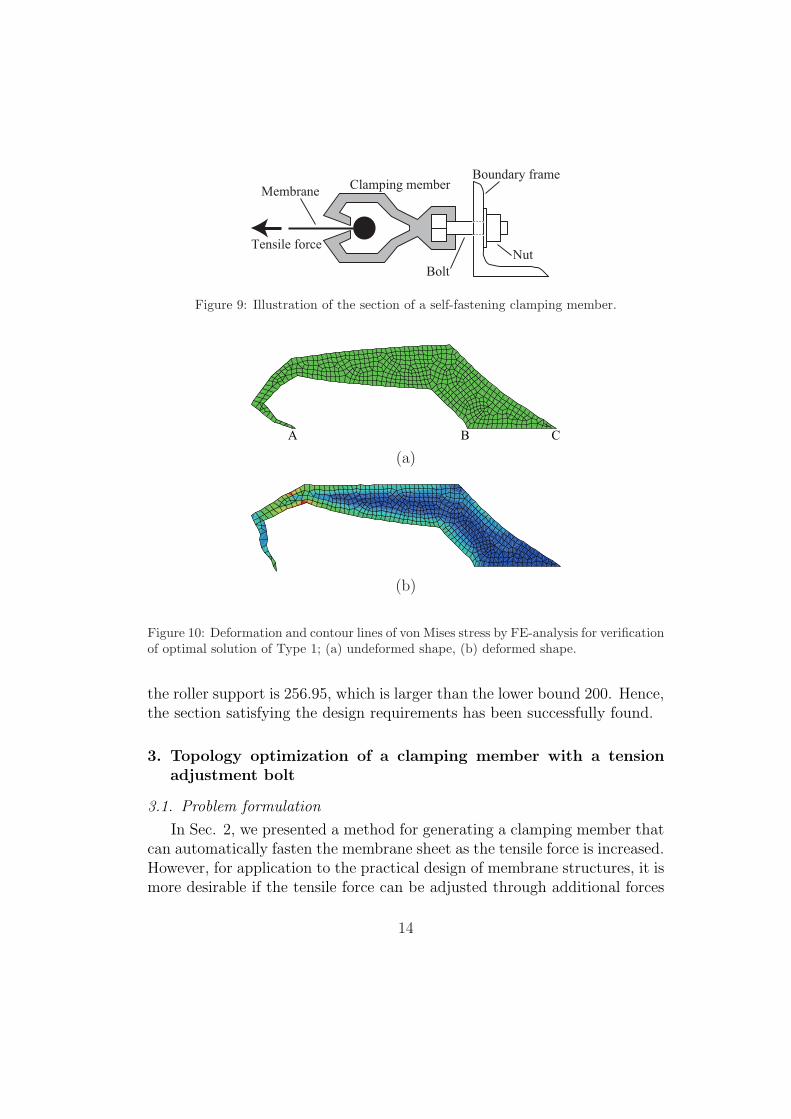
MembraneClamping member
Boundary frame
Bolt
NutTensile force
Figure 9: Illustration of the section of a self-fastening clamping member.
A CB
(a)
(b)
Figure 10: Deformation and contour lines of von Mises stress by FE-analysis for verificationof optimal solution of Type 1; (a) undeformed shape, (b) deformed shape.
the roller support is 256.95, which is larger than the lower bound 200. Hence,the section satisfying the design requirements has been successfully found.
3. Topology optimization of a clamping member with a tensionadjustment bolt
3.1. Problem formulation
In Sec. 2, we presented a method for generating a clamping member thatcan automatically fasten the membrane sheet as the tensile force is increased.However, for application to the practical design of membrane structures, it ismore desirable if the tensile force can be adjusted through additional forces
14

Membrane
Tensile Force
Boundary frame
Clamping member Bolt
Figure 11: Illustration a clamping member with tension adjustment bolt.
1 P
30 30
2
P 1
2
x
y
30 30
30
30
30
3
Figure 12: A frame model (Type 2).
to the clamping member as illustrated in Fig. 11. Therefore, we next considera problem with two loading conditions. The section is modeled by a frame,and its initial ground structure is as shown in Fig. 12. The load P1 is firstapplied at node 2 by the vertical bolt to pull the membrane for adjustmentof the tensile force. Then, the vertical location of node 2 is fixed and thesecond load P2 representing the tensile force of the membrane sheet is appliedat support 1.
Let U (1) and U (2) denote the x-directional displacements of support 1 inFig. 12 under specified static loads P1 and P2, respectively. We first minimizethe total structural volume V without stress constraint to obtain a frame withsmall number of members. The lower bound U (1)L (> 0) is given to ensurecapacity of adjustment by the bolt, and the lower bound U (2)L (< 0) is givenfor generating a frame with enough stiffness. Then the optimization problem
15

Figure 13: Optimal solution of Type 2 for Problem P5 under displacement constraint.
is formulated as follows:
P5 : minimize V (A) (6a)
subject to U(1)1 (A) ≥ U (1)L (6b)
U(2)1 (A) ≥ U (2)L (6c)
AL ≤ A ≤ AU (6d)
The optimal solution of Problem P5 is used as the new ground structurewith small number of members. Since the number of members need not bereduced anymore, the displacement U
(1)1 against P1 can be directly maximized
to obtain a good capacity of adjustment of membrane forces. Hence, weassign the stress constraints for both the states under P1 only and underapplication of P2 after constraining node 2, and solve the following problemadding the nodal coordinates X as variables:
P6 : maximize U(1)1 (A, X) (7a)
subject to U(2)1 (A, X) ≥ U (2)L (7b)
|σ(1)i (A,X)| ≤ σU, (i = 1, . . . ,m) (7c)
|σ(1)i (A,X) + σ
(2)i (A, X)| ≤ σU, (i = 1, . . . ,m) (7d)
AL ≤ A ≤ AU (7e)
XL ≤ X ≤ XU (7f)
where σ(1)i and σ
(2)i are the stresses of member i against P1 and P2, respec-
tively.
3.2. Numerical examples
Consider a frame as shown in Fig. 12. The load P1 = 300 is first appliedin negative y-direction at node 2. Then the y-directional displacement is
16
(a)
(b)
(c)
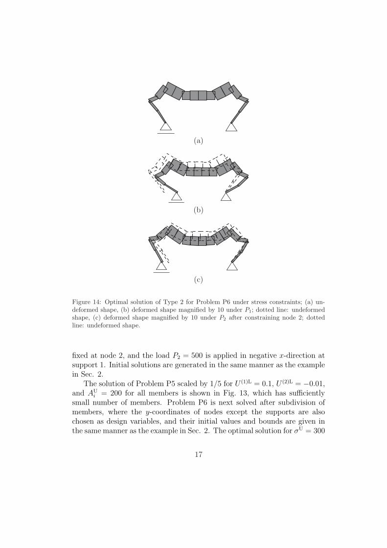
Figure 14: Optimal solution of Type 2 for Problem P6 under stress constraints; (a) un-deformed shape, (b) deformed shape magnified by 10 under P1; dotted line: undeformedshape, (c) deformed shape magnified by 10 under P2 after constraining node 2; dottedline: undeformed shape.
fixed at node 2, and the load P2 = 500 is applied in negative x-direction atsupport 1. Initial solutions are generated in the same manner as the examplein Sec. 2.
The solution of Problem P5 scaled by 1/5 for U (1)L = 0.1, U (2)L = −0.01,and AU
i = 200 for all members is shown in Fig. 13, which has sufficientlysmall number of members. Problem P6 is next solved after subdivision ofmembers, where the y-coordinates of nodes except the supports are alsochosen as design variables, and their initial values and bounds are given inthe same manner as the example in Sec. 2. The optimal solution for σU = 300
17

0.2
0.4
0.6
0.8
1
1.2
200 240 280 320 360 400
Dis
pla
cem
ent
Upper-bound stress
Figure 15: Relation between upper-bound stress and displacement.
is shown in Fig. 14(a) with the real scale for the heights of members. Thedeformed shape under P1 is shown in Fig. 14(b). We can see from Fig. 14(b)that the distance between the two supports decreases as the center node isdisplaced downward. Fig. 14(c) shows the state under P2 after constrainingvertical displacement at node 2.
Fig. 15 shows the relation between the upper-bound stress σU and thedisplacement U (1) of the optimal solution of P6. It can be confirmed fromFig. 15 that we can have larger deformation if the stress constraints arerelaxed.
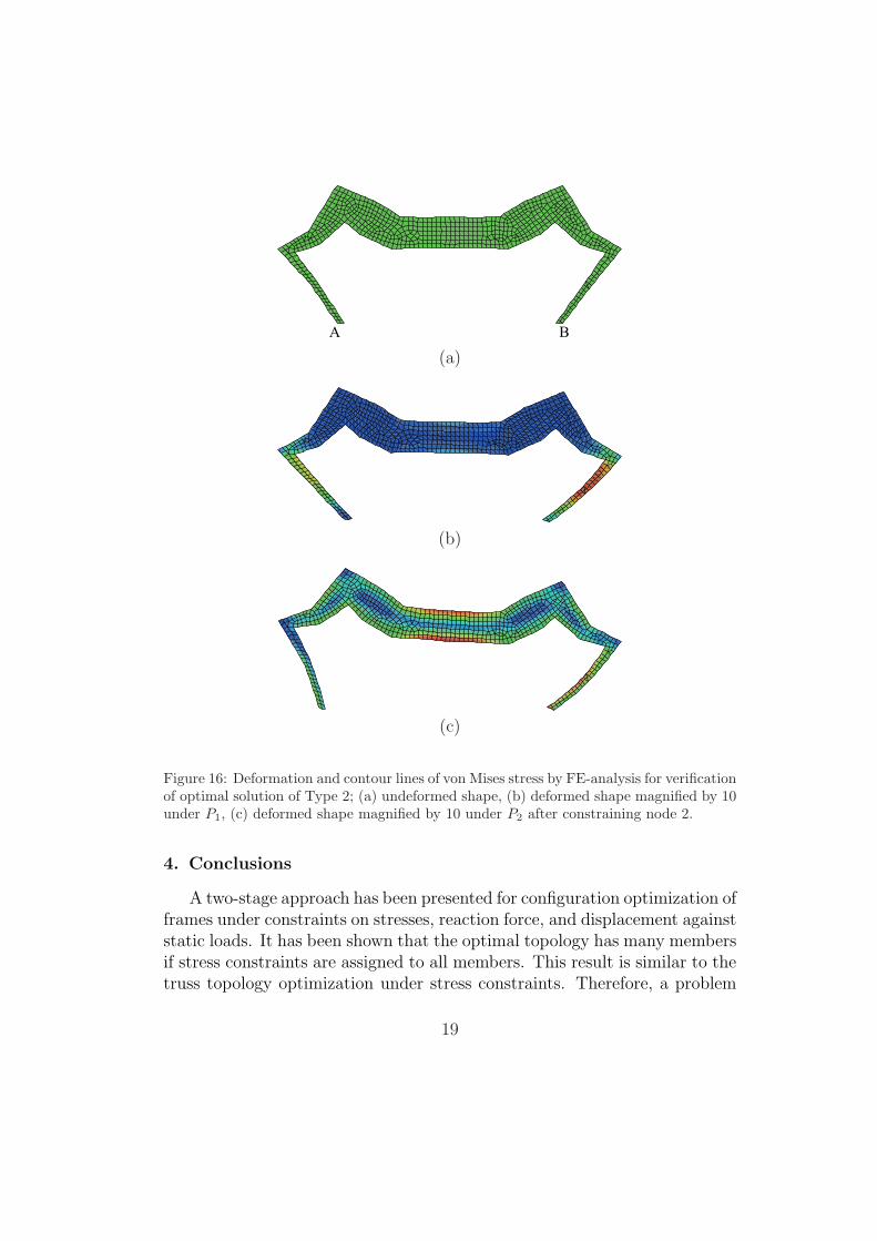
FE-analysis is carried out for verification of the result in Fig. 14 obtainedby the frame model for σU = 300. The FE-meshes in Fig. 16(a) are generatedin the same manner as those in Sec. 2. The plate is supported by rollerat point A and pin at point B. The deformed configuration under P1 withmagnification factor 10 is shown in Fig. 16(b). The contour lines show thevon Mises stress. The horizontal displacement of the support is 0.57424. Themaximum von Mises stress is 162.09, which is less than the upper bound.Fig. 16(c) shows the deformed configuration after application of P2. Themaximum von Mises stress is 253.62, which is less than the upper bound.Hence, the section satisfying the design requirements has been successfullyfound.
18
A B
(a)
(b)
(c)
Figure 16: Deformation and contour lines of von Mises stress by FE-analysis for verificationof optimal solution of Type 2; (a) undeformed shape, (b) deformed shape magnified by 10under P1, (c) deformed shape magnified by 10 under P2 after constraining node 2.
4. Conclusions
A two-stage approach has been presented for configuration optimization offrames under constraints on stresses, reaction force, and displacement againststatic loads. It has been shown that the optimal topology has many membersif stress constraints are assigned to all members. This result is similar to thetruss topology optimization under stress constraints. Therefore, a problem
19

without stress constraint and with artificial displacement constraint is firstsolved in the proposed two-stage approach.
A solution with small number of members can be found if very tight boundfor the displacement and very large upper bounds for cross-sectional areasare given, because the bending stiffness is proportional to the cubic power ofthe height, and the axial stiffness is proportional to the height of a memberwith solid section, and, accordingly, a member with larger height is moreefficient than that with smaller height when bending deformation dominatesover axial deformation. The stiffness of a member with small height can alsobe penalized using the approach similar to the SIMP method for continuumtopology optimization.
The frame with small number of members obtained in the first stage hasbeen further optimized under stress constraints after sub-division of mem-bers, where the vertical coordinates of nodes are also considered as designvariables. This way, the well-known difficulty in topology optimization understress constraints is successfully avoided.
As an application of the proposed approach, configuration optimizationhas been carried out to obtain a self-fastening clamping member of a frame-supported membrane structure. The total structural volume is minimizedunder constraint on the reaction so that the clamping force increases as theresult of increasing membrane tensile force. A shape of the device that pullsthe membrane efficiently by applying vertical force through a bolt can alsobe found using the proposed two-stage approach. This way, the total weightof a frame-supported membrane structure can be reduced, and the clampingforce and the tension force can be maintained through optimization.
AcknowledgmentFinancial support by Nohmura Foundation for Membrane Structure’s Tech-nology is gratefully acknowledged.
References
[1] M. P. Bendsøe, O. Sigmund, Topology Optimization: Theory, Methodsand Applications, Springer, Berlin, 2003.
[2] A. Kaveh, B. Hassani, S. Shojaee, S. M. Tavakkoli, Structural topologyoptimization using ant colony methodology, Eng. Struct. 30 (2008) 2559–2565.
20

[3] X. Huang, Y. M. Xie, Topology optimization of nonlinear structuresunder displacement loading, Eng. Struct. 30 (2008) 2057–2068.
[4] N. Lagaros, L. D. Psarras, M. Papadrakakis, G. Kokossalakis, Optimumdesign of steel structures with web opening, Eng. Struct. 30 (2008) 2528–2537.
[5] A. R. Mijar, C. Swan, J. S. Arora, I. Kosaka, Continuum topology op-timization for concept design of frame bracing system, J. Struct. Eng.124 (5) (1998) 541–550.
[6] H.-G. Kwak, S.-H. Noh, Determination of strut-and-tie models usingevolutionary structural optimization, Eng. Struct. 28 (2006) 1440–1449.
[7] P. Pan, M. Ohsaki, H. Tagawa, Shape optimization of H-beam flangefor maximum plastic energy dissipation, J. Struct. Eng. 133 (8) (2007)1176–1179.
[8] M. Ohsaki, H. Tagawa, P. Pan, Shape optimization of reduced beamsection for maximum plastic energy dissipation under cyclic loads, J.Const. Steel Res. 65 (2009) 1511–1519.
[9] M. Bruggi, On an alternative approach to stress constraints relaxationin topology optimization, Struct. Multidisc. Optim. 36 (2008) 125–141.
[10] H. Rahamia, A. Kaveh, Y. Gholipoura, Sizing, geometry and topologyoptimization of trusses via force method and genetic algorithm, Eng.Struct. 30 (2008) 2360–2369.
[11] H. Fredricson, T. Johansen, A. Klarbring, J. Petersson, Topology op-timization of frame structures with flexible joints, Struct. Multidisc.Optim. 25 (2003) 199–214.
[12] M. P. Saka, Optimum topological design of geometrically nonlinearsingle layer latticed domes using coupled genetic algorithm, Comput.Struct. 85 (2007) 1635–1646.
[13] M. Ohsaki, Optimization of Finite Dimensional Structures, CRC Press,Boca Raton, FL, 2010.
[14] M. Stolpe, K. Svanberg, A note on stress-constrained truss topologyoptimization, Struct. Multidisc. Optim. 25 (2003) 62–64.
21

[15] M. Ohsaki, N. Katoh, Topology optimization of trusses with stress andlocal constraints on nodal stability and member intersection, Struct.Multidisc. Optim. 29 (2005) 190–197.
[16] G. Cheng, X. Guo, ε-relaxed approach in structural topology optimiza-tion, Struct. Opt. 13 (1997) 258–266.
[17] P. Duysinx, M. P. Bendsøe, Topology optimization of continuum struc-tures with local stress constraints, Int. J. Numer. Meth. Eng. 43 (1998)1453–1478.
[18] G. I. N. Rozvany, M. Zhou, T. Birker, Generalized shape optimizationwithout homogenization, Struct. Optim. 4 (1992) 250–252.
[19] M.-J. Kim, G.-W. Jang, Y. Y. Kim, Application of a ground beam-jointtopology optimization method for multi-piece frame structure design, J.Mech. Design 130 (8) (2008) Paper–081401.
[20] A. Takezawa, S. Nishiwaki, K. Izui, M. Yoshimura, Structural opti-mization based on topology optimization techniques using frame ele-ments considering cross-sectional properties, Struct. Multidisc. Optim.34 (2007) 41–60.
[21] J.-Y. Kim, J.-B. Lee, A new technique for optimum cutting patterngeneration of membrane structures, Eng. Struct. 24 (6) (2002) 745–756.
[22] B. Maurin, R. Motro, The surface stress density method as a form-finding tool for tensile membranes, Eng. Struct. 20 (8) (1998) 712–719.
[23] M. I. Frecker, G. K. Ananthasuresh, S. Nishiwaki, N. Kikuchi, S. Kota,Topological synthesis of compliant mechanisms using multi-criteria op-timization, J. Mech. Design 119 (2) (1997) 238–245.
[24] O. Sigmund, On the design of compliant mechanisms using topologyoptimization, Mech. Struct. & Mach. 25 (4) (1997) 493–524.
[25] M. Ohsaki, S. Nishiwaki, Shape design of pin-jointed multistable compli-ant mechanism using snapthrough behavior, Struct. Multidisc. Optim.30 (2005) 327–334.
22

[26] P. E. Gill, W. Murray, M. A. Saunders, SNOPT: An SQP algorithm forlarge-scale constrained optimization, SIAM J. Optim. 12 (2002) 979–1006.
[27] H. Kim, R. T. Haftka, W. H. Mason, L. T. Watson, B. Grossman, Proba-bilistic modeling of errors from structural optimization based on multiplestarting points, Optim. Eng. 3 (2002) 415–430.
[28] P. Pan, M. Ohsaki, T. Kinoshita, Constraint approach to performance-based design of steel moment-resisting frames, Eng. Struct. 29 (2007)186–194.
[29] ABAQUS Ver. 6.9.2 Documentation, ABAQUS Inc., 2010.
23