
Configuration Guide - QoS(V100R006C00_01).pdf
95
Quidway S2700-52P-EI Ethernet Switch V100R006C00 Configuration Guide - QoS Issue 01 Date 2011-07-15 HUAWEI TECHNOLOGIES CO., LTD.
-
Upload
pedro-franco -
Category
Documents
-
view
229 -
download
4
Transcript of Configuration Guide - QoS(V100R006C00_01).pdf

Quidway S2700-52P-EI Ethernet SwitchV100R006C00
Configuration Guide - QoS
Issue 01
Date 2011-07-15
HUAWEI TECHNOLOGIES CO., LTD.

Copyright © Huawei Technologies Co., Ltd. 2011. All rights reserved.No part of this document may be reproduced or transmitted in any form or by any means without prior writtenconsent of Huawei Technologies Co., Ltd. Trademarks and Permissions
and other Huawei trademarks are trademarks of Huawei Technologies Co., Ltd.All other trademarks and trade names mentioned in this document are the property of their respective holders. NoticeThe purchased products, services and features are stipulated by the contract made between Huawei and thecustomer. All or part of the products, services and features described in this document may not be within thepurchase scope or the usage scope. Unless otherwise specified in the contract, all statements, information,and recommendations in this document are provided "AS IS" without warranties, guarantees or representationsof any kind, either express or implied.
The information in this document is subject to change without notice. Every effort has been made in thepreparation of this document to ensure accuracy of the contents, but all statements, information, andrecommendations in this document do not constitute the warranty of any kind, express or implied.
Huawei Technologies Co., Ltd.Address: Huawei Industrial Base
Bantian, LonggangShenzhen 518129People's Republic of China
Website: http://www.huawei.com
Email: [email protected]
Issue 01 (2011-07-15) Huawei Proprietary and ConfidentialCopyright © Huawei Technologies Co., Ltd.
i

About This Document
Intended AudienceThis document provides the basic concepts, configuration procedures, and configurationexamples in different application scenarios of the QoS supported by the S2700-52P-EI.
This document describes how to configure the QoS.
This document is intended for:
l Data configuration engineers
l Commissioning engineers
l Network monitoring engineers
l System maintenance engineers
Symbol ConventionsThe symbols that may be found in this document are defined as follows.
Symbol Description
DANGERIndicates a hazard with a high level of risk, which if notavoided, will result in death or serious injury.
WARNINGIndicates a hazard with a medium or low level of risk, whichif not avoided, could result in minor or moderate injury.
CAUTIONIndicates a potentially hazardous situation, which if notavoided, could result in equipment damage, data loss,performance degradation, or unexpected results.
TIP Indicates a tip that may help you solve a problem or savetime.
NOTE Provides additional information to emphasize or supplementimportant points of the main text.
Quidway S2700-52P-EI Ethernet SwitchConfiguration Guide - QoS About This Document
Issue 01 (2011-07-15) Huawei Proprietary and ConfidentialCopyright © Huawei Technologies Co., Ltd.
ii

Command ConventionsThe command conventions that may be found in this document are defined as follows.
Convention Description
Boldface The keywords of a command line are in boldface.
Italic Command arguments are in italics.
[ ] Items (keywords or arguments) in brackets [ ] are optional.
{ x | y | ... } Optional items are grouped in braces and separated byvertical bars. One item is selected.
[ x | y | ... ] Optional items are grouped in brackets and separated byvertical bars. One item is selected or no item is selected.
{ x | y | ... }* Optional items are grouped in braces and separated byvertical bars. A minimum of one item or a maximum of allitems can be selected.
[ x | y | ... ]* Optional items are grouped in brackets and separated byvertical bars. Several items or no item can be selected.
&<1-n> The parameter before the & sign can be repeated 1 to n times.
# A line starting with the # sign is comments.
Change HistoryUpdates between document issues are cumulative. Therefore, the latest document issue containsall updates made in previous issues.
Changes in Issue 01 (2011-07-15)Initial commercial release.
Quidway S2700-52P-EI Ethernet SwitchConfiguration Guide - QoS About This Document
Issue 01 (2011-07-15) Huawei Proprietary and ConfidentialCopyright © Huawei Technologies Co., Ltd.
iii

Contents
About This Document.....................................................................................................................ii
1 Class-based QoS Configuration.................................................................................................11.1 Introduction to Class-based QoS........................................................................................................................21.2 Class-based QoS Features Supported by the S2700-52P-EI..............................................................................21.3 Configuring Priority Mapping Based on Simple Traffic Classification.............................................................5
1.3.1 Establishing the Configuration Task.........................................................................................................51.3.2 Configuring an Interface to Trust the Priority of Packets..........................................................................61.3.3 (Optional) Setting the Default 802.1p Priority of an Interface..................................................................71.3.4 Configuring the Mapping Between DSCP Priorities and Other Priorities................................................71.3.5 Configuring IP Precedence Mappings.......................................................................................................81.3.6 (Optional) Configuring the Mapping Between Local Precedences and Queues.......................................81.3.7 Checking the Configuration.......................................................................................................................9
1.4 Creating a Traffic Policy Based on Complex Traffic Classification................................................................101.4.1 Establishing the Configuration Task.......................................................................................................101.4.2 Configuring Complex Traffic Classification...........................................................................................111.4.3 Configuring a Traffic Behavior...............................................................................................................171.4.4 Configuring a Traffic Policy....................................................................................................................211.4.5 Applying the Traffic Policy.....................................................................................................................221.4.6 Checking the Configuration.....................................................................................................................23
1.5 Configuring a Traffic Policy by Using Simplified QoS Commands................................................................241.5.1 Establishing the Configuration Task.......................................................................................................241.5.2 Configuring Traffic Policing for the Traffic That Matches an ACL Rule..............................................251.5.3 Filtering the Traffic That Matches an ACL Rule....................................................................................261.5.4 Re-marking the Traffic That Matches an ACL Rule...............................................................................271.5.5 Collecting Statistics on the Traffic That Matches an ACL Rule.............................................................291.5.6 Redirecting the Traffic That Matches an ACL Rule...............................................................................30
1.6 Maintaining Class-based QoS..........................................................................................................................321.6.1 Displaying the Flow-based Traffic Statistics...........................................................................................321.6.2 Clearing the Flow-based Traffic Statistics..............................................................................................32
1.7 Configuration Examples...................................................................................................................................331.7.1 Example for Configuring Priority Mapping Based on Simple Traffic Classification.............................331.7.2 Example for Re-marking the Priorities Based on Complex Traffic Classification.................................361.7.3 Example for Configuring Policy-based Routing.....................................................................................40
Quidway S2700-52P-EI Ethernet SwitchConfiguration Guide - QoS Contents
Issue 01 (2011-07-15) Huawei Proprietary and ConfidentialCopyright © Huawei Technologies Co., Ltd.
iv

1.7.4 Example for Configuring Traffic Statistics Based on Complex Traffic Classification...........................44
2 Traffic Policing and Traffic Shaping Configuration............................................................482.1 Overview of Traffic Policing and Traffic Shaping...........................................................................................49
2.1.1 Traffic Policing........................................................................................................................................492.1.2 Traffic Shaping........................................................................................................................................50
2.2 Configuring Traffic Policing Based on an Interface.........................................................................................522.2.1 Establishing the Configuration Task.......................................................................................................522.2.2 Limiting the Rate of Traffic on the Interface...........................................................................................522.2.3 Checking the Configuration.....................................................................................................................53
2.3 Configuring Traffic Policing Based on a Traffic Classifier.............................................................................532.3.1 Establishing the Configuration Task.......................................................................................................542.3.2 Configuring Complex Traffic Classification...........................................................................................542.3.3 Configuring a Traffic Policing Action.....................................................................................................542.3.4 Creating a Traffic Policy.........................................................................................................................552.3.5 Applying the Traffic Policy.....................................................................................................................562.3.6 Checking the Configuration.....................................................................................................................57
2.4 Configuring Traffic Shaping............................................................................................................................572.4.1 Establishing the Configuration Task.......................................................................................................572.4.2 Configuring Traffic Shaping on an Interface...........................................................................................582.4.3 (Optional) Setting the Length of the Interface Queue.............................................................................592.4.4 Configuring Traffic Shaping in an Interface Queue................................................................................592.4.5 Checking the Configuration.....................................................................................................................60
2.5 Maintaining Traffic Policing and Traffic Shaping...........................................................................................612.5.1 Displaying the Traffic Statistics..............................................................................................................612.5.2 Displaying the Maximum Length of a Queue.........................................................................................612.5.3 Clearing the Traffic Statistics..................................................................................................................62
2.6 Configuration Examples...................................................................................................................................622.6.1 Example for Configuring Traffic Policing Based on an Interface...........................................................622.6.2 Example for Configuring Traffic Policing Based on a Traffic Classifier...............................................652.6.3 Example for Configuring Traffic Shaping...............................................................................................69
3 Congestion Avoidance and Congestion Management Configuration..............................733.1 Overview of Congestion Avoidance and Congestion Management.................................................................74
3.1.1 Congestion Avoidance.............................................................................................................................743.1.2 Congestion Management.........................................................................................................................75
3.2 Configuring Congestion Avoidance.................................................................................................................763.2.1 Establishing the Configuration Task.......................................................................................................763.2.2 (Optional) Setting the Length of the Interface Queue.............................................................................773.2.3 (Optional) Setting the Minimum Size of the Static Buffer in an Interface Queue..................................773.2.4 (Optional) Configuring the CFI Field as the Internal Drop Priority........................................................783.2.5 Setting SRED Parameters........................................................................................................................793.2.6 Checking the Configuration.....................................................................................................................79
3.3 Configuring Congestion Management..............................................................................................................80
Quidway S2700-52P-EI Ethernet SwitchConfiguration Guide - QoS Contents
Issue 01 (2011-07-15) Huawei Proprietary and ConfidentialCopyright © Huawei Technologies Co., Ltd.
v

3.3.1 Establishing the Configuration Task.......................................................................................................803.3.2 (Optional) Setting the Length of the Interface Queue.............................................................................813.3.3 (Optional) Setting the Minimum Size of the Static Buffer in an Interface Queue..................................813.3.4 Setting the Scheduling Mode for an Interface Queue..............................................................................823.3.5 Checking the Configuration.....................................................................................................................83
3.4 Maintaining Congestion Avoidance and Congestion Management.................................................................833.4.1 Displaying the Queue-based Statistics....................................................................................................833.4.2 Clearing the Queue-based Statistics........................................................................................................84
3.5 Configuration Examples...................................................................................................................................853.5.1 Example for Configuring Congestion Avoidance and Congestion Management...................................85
Quidway S2700-52P-EI Ethernet SwitchConfiguration Guide - QoS Contents
Issue 01 (2011-07-15) Huawei Proprietary and ConfidentialCopyright © Huawei Technologies Co., Ltd.
vi

1 Class-based QoS Configuration
About This Chapter
This chapter describes the basic concepts of the traffic classifier, traffic behavior, traffic policy,and priority mapping, and configuration methods and configuration examples of the trafficpolicy based on complex traffic classification and priority mapping based on simple trafficclassification.
1.1 Introduction to Class-based QoSClass-based QoS is used to classify packets sharing common features into one class and providethe same QoS service for traffic of the same type by matching packets with certain rules. In thismanner, differentiated services are provided.
1.2 Class-based QoS Features Supported by the S2700-52P-EIThe S2700-52P-EI supports simple traffic classification, complex traffic classification, andpriority mapping.
1.3 Configuring Priority Mapping Based on Simple Traffic ClassificationAfter priority mapping based on simple traffic classification is configured, the S2700-52P-EImaps priorities of packets to PHBs and colors to provide differentiated services.
1.4 Creating a Traffic Policy Based on Complex Traffic ClassificationAfter the traffic policy based on complex traffic classification is configured, the S2700-52P-EI classifies packets according to the priority of packets and quintuple information. Then theS2700-52P-EI takes different traffic actions for packets matching classification conditions, suchas permit/deny, re-marking, and redirection.
1.5 Configuring a Traffic Policy by Using Simplified QoS CommandsBy using simplified QoS commands, you can configure traffic monitoring, traffic statistics,traffic redirection, traffic re-marking, and traffic mirroring. Compared with common QoScommands, simplified QoS commands make the configuration procedures easier because youdo not need to create traffic classifiers, traffic behaviors, and traffic policies independently.
1.6 Maintaining Class-based QoSIf the traffic statistics function is enabled, you can view and clear the flow-based traffic statistics.
1.7 Configuration ExamplesThis section provides several configuration examples of class-based QoS.
Quidway S2700-52P-EI Ethernet SwitchConfiguration Guide - QoS 1 Class-based QoS Configuration
Issue 01 (2011-07-15) Huawei Proprietary and ConfidentialCopyright © Huawei Technologies Co., Ltd.
1
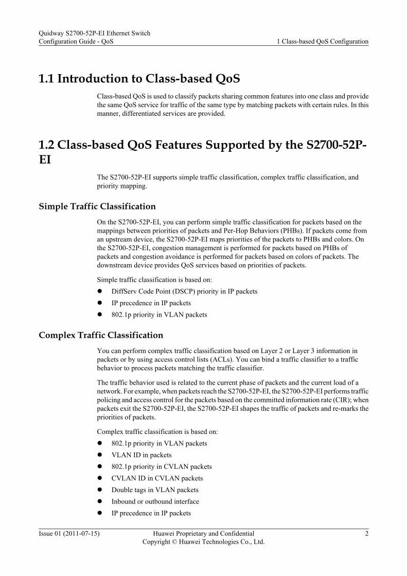
1.1 Introduction to Class-based QoSClass-based QoS is used to classify packets sharing common features into one class and providethe same QoS service for traffic of the same type by matching packets with certain rules. In thismanner, differentiated services are provided.
1.2 Class-based QoS Features Supported by the S2700-52P-EI
The S2700-52P-EI supports simple traffic classification, complex traffic classification, andpriority mapping.
Simple Traffic ClassificationOn the S2700-52P-EI, you can perform simple traffic classification for packets based on themappings between priorities of packets and Per-Hop Behaviors (PHBs). If packets come froman upstream device, the S2700-52P-EI maps priorities of the packets to PHBs and colors. Onthe S2700-52P-EI, congestion management is performed for packets based on PHBs ofpackets and congestion avoidance is performed for packets based on colors of packets. Thedownstream device provides QoS services based on priorities of packets.
Simple traffic classification is based on:l DiffServ Code Point (DSCP) priority in IP packetsl IP precedence in IP packetsl 802.1p priority in VLAN packets
Complex Traffic ClassificationYou can perform complex traffic classification based on Layer 2 or Layer 3 information inpackets or by using access control lists (ACLs). You can bind a traffic classifier to a trafficbehavior to process packets matching the traffic classifier.
The traffic behavior used is related to the current phase of packets and the current load of anetwork. For example, when packets reach the S2700-52P-EI, the S2700-52P-EI performs trafficpolicing and access control for the packets based on the committed information rate (CIR); whenpackets exit the S2700-52P-EI, the S2700-52P-EI shapes the traffic of packets and re-marks thepriorities of packets.
Complex traffic classification is based on:l 802.1p priority in VLAN packetsl VLAN ID in packetsl 802.1p priority in CVLAN packetsl CVLAN ID in CVLAN packetsl Double tags in VLAN packetsl Inbound or outbound interfacel IP precedence in IP packets
Quidway S2700-52P-EI Ethernet SwitchConfiguration Guide - QoS 1 Class-based QoS Configuration
Issue 01 (2011-07-15) Huawei Proprietary and ConfidentialCopyright © Huawei Technologies Co., Ltd.
2

l DSCP priority in IP packetsl SYN Flag field in Transmission Control Protocol (TCP) packetsl Source MAC addressl Destination MAC addressl Protocol type field encapsulated in Layer 2 packetsl Layer 3 protocol typel ACLl Discarded packets
Priority MappingDifferent packets carry different precedence fields. For example, VLAN packets carry the 802.1pfield, and IP packets carry the DSCP field or IP precedence. The mappings between priorityfields must be configured on gateways to retain priorities of packets when the packets traversedifferent networks.
To ensure QoS for different packets, when packets reach the S2700-52P-EI, the S2700-52P-EI maps packet priorities to 802.1p priorities. The S2700-52P-EI then maps 802.1p priorities inpackets or the default 802.1p priority of an interface to local priorities, determines the queuesthat packets enter based on the mappings between internal priorities and queues, and performstraffic shaping and queue scheduling. When packets are sent out from the S2700-52P-EI, theS2700-52P-EI re-marks priorities of packets so that the downstream device can providedifferentiated QoS based on packet priorities.
Table 1-1 and Table 1-2 list the mappings between 802.1p priorities and internal priorities, andbetween internal priorities and queues.
Table 1-1 Mappings between 802.1p priorities and internal priorities
802.1p Priority Internal Priority
0 BE
1 AF1
2 AF2
3 AF3
4 AF4
5 EF
6 CS6
7 CS7
Table 1-2 Mappings between internal priorities and queues
Internal Priority Queue Index
BE 0
Quidway S2700-52P-EI Ethernet SwitchConfiguration Guide - QoS 1 Class-based QoS Configuration
Issue 01 (2011-07-15) Huawei Proprietary and ConfidentialCopyright © Huawei Technologies Co., Ltd.
3

Internal Priority Queue Index
AF1 1
AF2 2
AF3 3
AF4 4
EF 5
CS6 6
CS7 7
NOTE
The color is used to determine whether the packets are discarded, and is independent of the mapping ofinternal priorities and queues.
Traffic BehaviorComplex traffic classification is used to provide differentiated services. Traffic classificationtakes effect only when it is associated with traffic control or resource allocation actions.
The S2700-52P-EI supports the combinations of the following traffic actions:
l Deny/PermitThis traffic control action is the simplest. The S2700-52P-EI controls network traffic byforwarding or discarding packets.
l Re-markingThis traffic control action is used to set the precedence field in a packet. Packets carrydifferent precedence fields on various networks. For example, packets carry the 802.1pfield on a VLAN network, and the DSCP field on an IP network. Therefore, the S2700-52P-EI is required to re-mark the precedence fields of packets according to the network type.Generally, a device at the border of a network needs to mark the precedence fields ofincoming packets; the device at the core of a network provides corresponding QoS servicesbased on the precedence fields marked by the border device, or re-marks the precedencefields based on its configuration rule.
l RedirectionThis traffic control action indicates that the S2700-52P-EI does not forward packetsaccording to the destination address but redirects them to the CPU, the specified interface,or the specified next hop address. The S2700-52P-EI can specify up to four next hops.By using redirection, you can implement policy-based routing (PBR). The PBR is static.When no next hop is available, the S2700-52P-EI forwards the packets to the originaldestination.The S2700-52P-EI can redirect only incoming packets.
l Traffic policingIt is a traffic control action used to limit traffic and resources by monitoring the rate limitof the traffic. By using traffic policing, the S2700-52P-EI can discard, and re-mark thecolors and CoS of packets whose rate exceeds the rate limit.
Quidway S2700-52P-EI Ethernet SwitchConfiguration Guide - QoS 1 Class-based QoS Configuration
Issue 01 (2011-07-15) Huawei Proprietary and ConfidentialCopyright © Huawei Technologies Co., Ltd.
4

Here, traffic policing based on a traffic Classification is implemented. For details abouttraffic policing, see 2 Traffic Policing and Traffic Shaping Configuration.
l Flow mirroring
Flow mirroring is used to copy the specified data packets to a specified destination to locatefaults on a network.
For details about flow mirroring, see Mirroring in the Quidway S2700-52P-EI EthernetSwitches Configuration Guide - Device Management.
l Traffic statistics
The traffic statistics action is used to collect data packets of specified service flows, thatis, data packets matching complex traffic classification rules on the S2700-52P-EI.
Traffic Policy
A traffic policy is a QoS policy in which traffic classifiers are bound to traffic behaviors. Youcan bind a specified traffic classifier to a traffic behavior through the traffic policy to betterperform QoS.
1.3 Configuring Priority Mapping Based on Simple TrafficClassification
After priority mapping based on simple traffic classification is configured, the S2700-52P-EImaps priorities of packets to PHBs and colors to provide differentiated services.
1.3.1 Establishing the Configuration TaskBefore configuring priority mapping based on simple traffic classification, familiarize yourselfwith the applicable environment, complete the pre-configuration tasks, and obtain the requireddata. This helps you complete the configuration task quickly and accurately.
Applicable Environment
When packets enter the S2700-52P-EI, the S2700-52P-EI maps DSCP priorities or IP prioritiesto 802.1p priorities according to the mapping and determines the queue that packets enter.
Pre-configuration Tasks
Before configuring priority mapping based on simple traffic classification, complete thefollowing tasks:
l Configuring the physical parameters of interfaces
l Setting link layer attributes of interfaces
Data Preparation
To configure priority mapping based on simple traffic classification, you need the followingdata.
Quidway S2700-52P-EI Ethernet SwitchConfiguration Guide - QoS 1 Class-based QoS Configuration
Issue 01 (2011-07-15) Huawei Proprietary and ConfidentialCopyright © Huawei Technologies Co., Ltd.
5

No. Data
1 Types and numbers of the interface.
2 Input DSCP priority, output 802.1p priority, drop precedence, or new DSCP priority.
3 Input IP priority, output 802.1p priority, or IP priority.
1.3.2 Configuring an Interface to Trust the Priority of PacketsAfter an interface is configured to trust the priority of packets, the S2700-52P-EI performspriority mapping based on the specified priority.
Context
The S2700-52P-EI provides the following priority trust modes:l Trusting the 802.1p priority of packets
The inbound interface maps 802.1p priorities of tagged packets to internal priorities basedon the default mapping; the S2700-52P-EI adds the default 802.1p priority of the interfaceto untagged packets and maps the default 802.1p priority of the packets to internal priorities.
l Trusting the DSCP priority of packetsThe system searches the DSCP priority mapping table based on DSCP priorities in packets,re-marks 802.1p priorities or DSCP priorities in packets, or maps DSCP priorities in packetsto drop priorities.
l Trusting the IP priority of packetsThe system searches the IP priority mapping table based on IP priorities in packets and re-marks 802.1p priorities or IP priorities in packets.
If you need to set the same trust priority on multiple interfaces, you can perform the configurationon a port group to simplify the configuration.
Procedure
Step 1 Run:system-view
The system view is displayed.
Step 2 Run:interface interface-type interface-number
The interface view is displayed.
Or run the port-group port-group-name command to display the port group view.
NOTE
l The interface type can be Ethernet, GE, or Eth-Trunk.
l You need to create a port group before performing this task. For details on how to create a port group,see (Optional) Configuring the Interface Group in the Quidway S2700-52P-EI Ethernet SwitchesConfiguration Guide - Ethernet.
Quidway S2700-52P-EI Ethernet SwitchConfiguration Guide - QoS 1 Class-based QoS Configuration
Issue 01 (2011-07-15) Huawei Proprietary and ConfidentialCopyright © Huawei Technologies Co., Ltd.
6
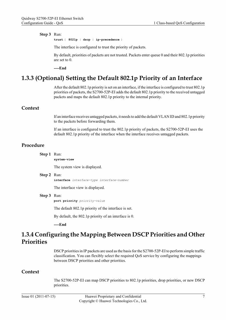
Step 3 Run:trust { 8021p | dscp | ip-precedence }
The interface is configured to trust the priority of packets.
By default, priorities of packets are not trusted. Packets enter queue 0 and their 802.1p prioritiesare set to 0.
----End
1.3.3 (Optional) Setting the Default 802.1p Priority of an InterfaceAfter the default 802.1p priority is set on an interface, if the interface is configured to trust 802.1ppriorities of packets, the S2700-52P-EI adds the default 802.1p priority to the received untaggedpackets and maps the default 802.1p priority to the internal priority.
ContextIf an interface receives untagged packets, it needs to add the default VLAN ID and 802.1p priorityto the packets before forwarding them.
If an interface is configured to trust the 802.1p priority of packets, the S2700-52P-EI uses thedefault 802.1p priority of the interface when the interface receives untagged packets.
Procedure
Step 1 Run:system-view
The system view is displayed.
Step 2 Run:interface interface-type interface-number
The interface view is displayed.
Step 3 Run:port priority priority-value
The default 802.1p priority of the interface is set.
By default, the 802.1p priority of an interface is 0.
----End
1.3.4 Configuring the Mapping Between DSCP Priorities and OtherPriorities
DSCP priorities in IP packets are used as the basis for the S2700-52P-EI to perform simple trafficclassification. You can flexibly select the required QoS service by configuring the mappingsbetween DSCP priorities and other priorities.
ContextThe S2700-52P-EI can map DSCP priorities to 802.1p priorities, drop priorities, or new DSCPpriorities.
Quidway S2700-52P-EI Ethernet SwitchConfiguration Guide - QoS 1 Class-based QoS Configuration
Issue 01 (2011-07-15) Huawei Proprietary and ConfidentialCopyright © Huawei Technologies Co., Ltd.
7
Procedure
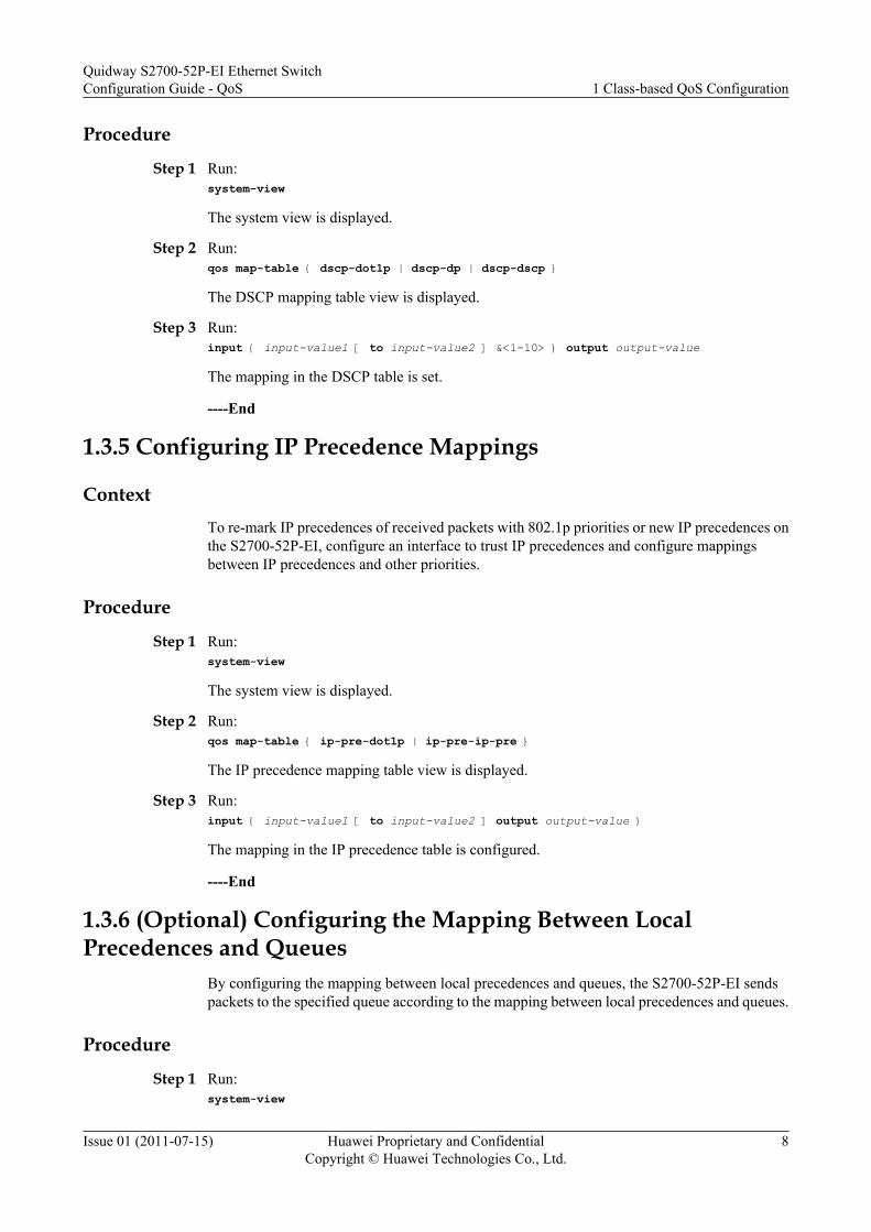
Step 1 Run:system-view
The system view is displayed.
Step 2 Run:qos map-table { dscp-dot1p | dscp-dp | dscp-dscp }
The DSCP mapping table view is displayed.
Step 3 Run:input { input-value1 [ to input-value2 ] &<1-10> } output output-value
The mapping in the DSCP table is set.
----End
1.3.5 Configuring IP Precedence Mappings
ContextTo re-mark IP precedences of received packets with 802.1p priorities or new IP precedences onthe S2700-52P-EI, configure an interface to trust IP precedences and configure mappingsbetween IP precedences and other priorities.
Procedure
Step 1 Run:system-view
The system view is displayed.
Step 2 Run:qos map-table { ip-pre-dot1p | ip-pre-ip-pre }
The IP precedence mapping table view is displayed.
Step 3 Run:input { input-value1 [ to input-value2 ] output output-value }
The mapping in the IP precedence table is configured.
----End
1.3.6 (Optional) Configuring the Mapping Between LocalPrecedences and Queues
By configuring the mapping between local precedences and queues, the S2700-52P-EI sendspackets to the specified queue according to the mapping between local precedences and queues.
Procedure
Step 1 Run:system-view
Quidway S2700-52P-EI Ethernet SwitchConfiguration Guide - QoS 1 Class-based QoS Configuration
Issue 01 (2011-07-15) Huawei Proprietary and ConfidentialCopyright © Huawei Technologies Co., Ltd.
8
The system view is displayed.
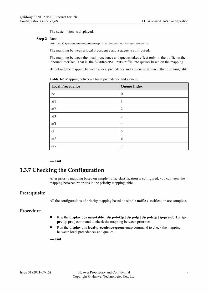
Step 2 Run:qos local-precedence-queue-map local-precedence queue-index
The mapping between a local precedence and a queue is configured.
The mapping between the local precedence and queues takes effect only on the traffic on theinbound interface. That is, the S2700-52P-EI puts traffic into queues based on the mapping.
By default, the mapping between a local precedence and a queue is shown in the following table.
Table 1-3 Mapping between a local precedence and a queue
Local Precedence Queue Index
be 0
af1 1
af2 2
af3 3
af4 4
ef 5
cs6 6
cs7 7
----End
1.3.7 Checking the ConfigurationAfter priority mapping based on simple traffic classification is configured, you can view themapping between priorities in the priority mapping table.
PrerequisiteAll the configurations of priority mapping based on simple traffic classification are complete.
Procedurel Run the display qos map-table [ dscp-dot1p | dscp-dp | dscp-dscp | ip-pre-dot1p | ip-
pre-ip-pre ] command to check the mapping between priorities.l Run the display qos local-precedence-queue-map command to check the mapping
between local precedences and queues.
----End
Quidway S2700-52P-EI Ethernet SwitchConfiguration Guide - QoS 1 Class-based QoS Configuration
Issue 01 (2011-07-15) Huawei Proprietary and ConfidentialCopyright © Huawei Technologies Co., Ltd.
9
1.4 Creating a Traffic Policy Based on Complex TrafficClassification
After the traffic policy based on complex traffic classification is configured, the S2700-52P-EI classifies packets according to the priority of packets and quintuple information. Then theS2700-52P-EI takes different traffic actions for packets matching classification conditions, suchas permit/deny, re-marking, and redirection.
1.4.1 Establishing the Configuration TaskBefore configuring the traffic policy based on complex traffic classification, familiarize yourselfwith the applicable environment, complete the pre-configuration tasks, and obtain the requireddata. This helps you complete the configuration task quickly and accurately.
Applicable Environment
At the ingress of a network, the S2700-52P-EI functions as a border node. To limit the incomingtraffic on a network, the S2700-52P-EI can provide differentiated services for various servicesaccording to the DSCP field, protocol type, IP address, port number, fragmentation type, andtime range of packets. In this case, you need to create a traffic policy based on complex trafficclassification.
Generally, complex traffic classification is configured on a border node, and simple trafficclassification is configured on a core node.
Pre-configuration Tasks
Before creating a traffic policy based on complex traffic classification, complete the followingtasks:
l Configuring the physical parameters of interfacesl Setting link layer attributes of interfacesl Configuring routing protocols to ensure the connectivity of the networkl Configuring ACLs if ACLs are used as matching rules for traffic classification
Data Preparation
To create a traffic policy based on complex traffic classification, you need the following data.
No. Data
1 Name of the traffic classifier and matching rules of the traffic classifier
2 Name of the traffic behavior and related parameters
3 Name of the traffic policy
4 Interface that the traffic policy is applied to and ID of the VLAN
Quidway S2700-52P-EI Ethernet SwitchConfiguration Guide - QoS 1 Class-based QoS Configuration
Issue 01 (2011-07-15) Huawei Proprietary and ConfidentialCopyright © Huawei Technologies Co., Ltd.
10
1.4.2 Configuring Complex Traffic ClassificationThe S2700-52P-EI can classify traffic according to the ACL, and the Layer 2 information andLayer 3 information in packets.
Creating a Traffic Classifier Based on Layer 2 InformationAfter traffic classification based on Layer 2 information is configured, the S2700-52P-EIclassifies packets based on the Layer 2 information including the 802.1p priority, VLAN ID,source/destination MAC address, incoming/outgoing interface, and Layer 2 protocol type.
ContextDo as follows on the S2700-52P-EI where a traffic classifier based on Layer 2 information needsto be created.
Procedure
Step 1 Run:system-view
The system view is displayed.
Step 2 Run:traffic classifier classifier-name [ operator { and | or } ]
A traffic classifier based on Layer 2 information is created and the traffic classifier view isdisplayed.
The and parameter indicates that the relationship between rules in a traffic classifier is "AND".That is, the packets match a traffic classifier only when the packets match all non-ACL rulesand an ACL rule in the traffic classifier. The or parameter indicates that the relationship betweenrules in a traffic classifier is "OR". That is, the packets match a traffic classifier when the packetsmatch a rule in the traffic classifier.
By default, the relationship between rules in a traffic classifier is AND.
Step 3 Run the following commands as required.l To define matching rules based on the 802.1p priority in the inner VLAN tag of QinQ packets,
run:if-match cvlan-8021p { 8021p-value } &<1-8>
l To define matching rules based on the 802.1p priority of packets in a VLAN, run:if-match 8021p { 8021p-value } &<1-8>
l To define matching rules based on the VLAN ID in the inner VLAN tag or the VLAN IDsin inner and outer tags of QinQ packets, run:
l To define matching rules based on the outer VLAN ID or VLAN IDs of inner and outer tagsof QinQ packets, run:if-match vlan-id start-vlan-id [ to end-vlan-id ] [ cvlan-id cvlan-id ]
l To define matching rules based on discarded packets, run:if-match discard
l To define matching rules based on double tags of QinQ packets, run:if-match double-tag
Quidway S2700-52P-EI Ethernet SwitchConfiguration Guide - QoS 1 Class-based QoS Configuration
Issue 01 (2011-07-15) Huawei Proprietary and ConfidentialCopyright © Huawei Technologies Co., Ltd.
11
l To define matching rules based on the destination MAC address, run:if-match destination-mac mac-address [ mac-address-mask ]
l To define matching rules based on the source MAC address, run:if-match source-mac mac-address [ mac-address-mask ]
l To define matching rules based on the incoming interface, run:if-match inbound-interface interface-type interface-number
l To define matching rules based on the outgoing interface, run:if-match outbound-interface interface-type interface-number
l To define matching rules based on the protocol field in the Ethernet frame header, run:if-match l2-protocol{ arp | ip | mpls | rarp | protocol-value }
l To define matching rules based on all the packets, run:if-match any
----End
Creating a Traffic Classifier Based on Layer 3 Information
After traffic classification based on Layer 3 information is configured, the S2700-52P-EIclassifies packets according to Layer 3 information in packets.
Context
Do as follows on the S2700-52P-EI where a traffic classifier based on Layer 3 information needsto be created.
Procedure
Step 1 Run:system-view
The system view is displayed.
Step 2 Run:traffic classifier classifier-name [ operator { and | or } ]
A traffic classifier based on Layer 3 information is created and the traffic classifier view isdisplayed.
The and parameter indicates that the relationship between rules in a traffic classifier is AND.That is, the packets match a traffic classifier only when the packets match all non-ACL rulesand an ACL rule in the traffic classifier. The or parameter indicates that the relationship betweenrules in a traffic classifier is OR. That is, the packets match a traffic classifier when the packetsmatch a rule in the traffic classifier.
By default, the relationship between rules in a traffic classifier is AND.
Step 3 Run the following commands as required.
l To define matching rules based on the DSCP priority of IP packets, run:if-match dscp dscp-value &<1-8>
l To define matching rules based on the IP priority of IP packets, run:if-match ip-precedence ip-precedence-value &<1-8>
Quidway S2700-52P-EI Ethernet SwitchConfiguration Guide - QoS 1 Class-based QoS Configuration
Issue 01 (2011-07-15) Huawei Proprietary and ConfidentialCopyright © Huawei Technologies Co., Ltd.
12

NOTE
In a traffic classifier where the relationship between rules is AND, the if-match dscp and if-match ip-precedence commands cannot be used simultaneously.
l To define matching rules based on the Layer 3 protocol type, run:if-match protocol { ip | ipv6 }
l To define matching rules based on the SYN Flag field of TCP packets, run:if-match tcp syn-flag syn-flag { syn-flag-value | ack | fin | psh | rst | syn | urg }
----End
Creating a Traffic Classifier Based on an ACLAfter traffic classification based on an ACL is configured, the S2700-52P-EI classifies packetsbased on the ACL.
ContextThe S2700-52P-EI can use an ACL to classify packets based on the IP quintuple.
The S2700-52P-EI supports basic ACLs, Layer 2 ACLs, user-defined ACLs and advancedACLs.
l Basic ACLs are used to classify data packets based on the source IP address, fragmentationflag, and time segment of packets.
l Advanced ACLs are used to classify and define data packets based on the source IP address,destination IP address, source port number, destination port number, fragmentation flag,time segment, and protocol type of packets.
l Layer 2 ACLs are used to classify data packets based on the source MAC address anddestination MAC address of packets.
l User-defined ACLs process data packets according to the rules defined by users.
Create a traffic classifier based on an ACL.
Procedurel Creating a traffic classifier based on a basic ACL
1. Run:system-view
The system view is displayed.2. Run:
acl [ number ] basic-acl-number
A basic ACL is created and the ACL view is displayed.3. (Optional) Run:
step step-value
The step value between ACL rule IDs is set.4. Run:
rule [ rule-id ] { deny | permit } [ fragment | logging | source { source-address source-wildcard | any } | time-range time-name ]*
A basic ACL4 rule is created.
Quidway S2700-52P-EI Ethernet SwitchConfiguration Guide - QoS 1 Class-based QoS Configuration
Issue 01 (2011-07-15) Huawei Proprietary and ConfidentialCopyright © Huawei Technologies Co., Ltd.
13

5. Run:quit
Return to the system view.6. Run:
traffic classifier classifier-name [ operator { and | or } ]
A traffic classifier is created and the traffic classifier view is displayed.
The and parameter indicates that the relationship between rules in a traffic classifieris AND. That is, packets match a traffic classifier only when the packets match allnon-ACL rules and an ACL rule in the traffic classifier. The or parameter indicatesthat the relationship between rules in a traffic classifier is OR. That is, packets matcha traffic classifier when the packets match a rule in the traffic classifier.
By default, the relationship between rules in a traffic classifier is AND.7. Run:
if-match acl basic-acl-number
A traffic classifier based on a basic ACL is created.l Creating a traffic classifier based on an advanced ACL
1. Run:system-view
The system view is displayed.2. Run:
acl [ number ] advanced-acl-number
An advanced ACL is created and the ACL view is displayed.
NOTE
advanced-acl-number specifies the number of an advanced ACL. The value is an integer thatranges from 3000 to 3999.
3. Run the following commands as required.– To define an advanced ACL for Genetic Routing Encapsulation (GRE), Internet
Group Management Protocol (IGMP), IP, IPinIP, or Open Shortest Path First(OSPF) packets, run:rule [ rule-id ] { deny | permit } { protocol-number | gre | igmp | ip | ipinip | ospf } [ tos tos ] [ destination { destination-address destination-wildcard | any } | dscp dscp | fragment | logging | precedence precedence | source { source-address source-wildcard | any } | time-range time-name ]*
– To define an advanced ACL for Transmission Control Protocol (TCP) packets,run:rule [ rule-id ] { deny | permit } { protocol-number | tcp } [ tos tos ] [ destination { destination-address destination-wildcard | any } | destination-port { eq | gt | lt | range } port | dscp dscp | fragment | precedence precedence | source { source-address source-wildcard | any } | source-port { eq | gt | lt | range } port | tcp-flag { tcp-value | ack | fin | psh | rst | syn | urg } * | time-range time-name ]*
– To define an advanced ACL for User Datagram Protocol (UDP) packets, run:rule [ rule-id ] { deny | permit } { protocol-number | udp } [ tos tos ] [ destination { destination-address destination-wildcard | any } | destination-port { eq | gt | lt | range } port | dscp dscp | fragment | logging | precedence precedence | source { source-address
Quidway S2700-52P-EI Ethernet SwitchConfiguration Guide - QoS 1 Class-based QoS Configuration
Issue 01 (2011-07-15) Huawei Proprietary and ConfidentialCopyright © Huawei Technologies Co., Ltd.
14
source-wildcard | any } | source-port { eq | gt | lt | range } port | time-range time-name ]*
– To define an advanced ACL for Internet Control Message Protocol (ICMP)packets, run:rule [ rule-id ] { deny | permit } { protocol-number | icmp } [ tos tos ] [ destination { destination-address destination-wildcard | any } | dscp dscp | fragment | logging | icmp-type { icmp-name | icmp-type icmp-code } | precedence precedence | source { source-address source-wildcard | any } | time-range time-name ]*
4. Run:quit
Return to the system view.5. Run:
traffic classifier classifier-name [ operator { and | or } ]
A traffic classifier is created and the traffic classifier view is displayed.
The and parameter indicates that the relationship between rules in a traffic classifieris AND. That is, packets match a traffic classifier only when the packets match allnon-ACL rules and an ACL rule in the traffic classifier. The or parameter indicatesthat the relationship between rules in a traffic classifier is OR. That is, packets matcha traffic classifier when the packets match a rule in the traffic classifier.
By default, the relationship between rules in a traffic classifier is AND.6. Run:
if-match acl advanced-acl-number
A traffic classifier based on an advanced ACL is created.l Creating a traffic classifier based on a Layer 2 ACL
1. Run:system-view
The system view is displayed.2. Run:
acl [ number ] mac-acl-number
A Layer 2 ACL is created and the ACL view is displayed.
NOTE
mac-acl-number specifies the number of a Layer 2 ACL. The value is an integer that rangesfrom 4000 to 4999.
3. (Optional) Run:step step-value
The step value between ACL rule IDs is set.4. Run:
rule [ rule-id ] { permit | deny } [ { ether-ii | 802.3 | snap } | l2-protocol type-value [ type-mask ] | destination-mac dest-mac-address [ dest-mac-mask ] | source-mac source-mac-address [ source-mac-mask ] | vlan-id vlan-id [ vlan-id-mask ] | 8021p 802.1p-value | cvlan-id cvlan-id [ cvlan-id-mask ] | cvlan-8021p 802.1p-value | double-tag ] * [ time-range time-range-name ]
A Layer 2 ACL rule is created.
Quidway S2700-52P-EI Ethernet SwitchConfiguration Guide - QoS 1 Class-based QoS Configuration
Issue 01 (2011-07-15) Huawei Proprietary and ConfidentialCopyright © Huawei Technologies Co., Ltd.
15
5. Run:quit
Return to the system view.6. Run:
traffic classifier classifier-name [ operator { and | or } ]
A traffic classifier is created and the traffic classifier view is displayed.
The and parameter indicates that the relationship between rules in a traffic classifieris AND. That is, packets match a traffic classifier only when the packets match allnon-ACL rules and an ACL rule in the traffic classifier. The or parameter indicatesthat the relationship between rules in a traffic classifier is OR. That is, packets matcha traffic classifier when the packets match a rule in the traffic classifier.
By default, the relationship between rules in a traffic classifier is AND.7. Run:
if-match acl l2-acl-number
A traffic classifier based on a Layer 2 ACL is created.l Creating a traffic classifier based on a user-defined ACL
1. Run:system-view
The system view is displayed.2. Run:
acl [ number ] user-defined-acl-number
A user-defined ACL is created and the user-defined ACL view is displayed.
NOTE
user-defined-acl-number specified the number of a user-defined ACL. The value is an integerthat ranges from 5000 to 5999.
3. (Optional) Run:step step-value
The step value between ACL rule IDs is set.4. Run:
quit
Return to the system view.5. Run:
traffic classifier classifier-name [ operator { and | or } ]
A traffic classifier is created and the traffic classifier view is displayed.
and indicates the relationship between rules is AND. That is, packets must match allthe non-ACL rules and one of the ACL rules of the traffic classifier. or indicates therelationship between rules is OR. That is, packets need to match only one rule of thetraffic classifier.
By default, the relationship between rules in a traffic classifier is AND.6. Run:
if-match acl user-defined-acl-number
Quidway S2700-52P-EI Ethernet SwitchConfiguration Guide - QoS 1 Class-based QoS Configuration
Issue 01 (2011-07-15) Huawei Proprietary and ConfidentialCopyright © Huawei Technologies Co., Ltd.
16

A traffic classifier based on a user-defined ACL is configured.
----End
1.4.3 Configuring a Traffic BehaviorThe S2700-52P-EI supports the actions of permit/deny, re-marking, redirection, traffic policing,flow mirroring, and traffic statistics, which can be configured as required.
Configuring the Deny or Permit ActionBy configuring the deny or permit action, the S2700-52P-EI rejects or permits packets matchingtraffic classification rules to control the network traffic.
Procedure
Step 1 Run:system-view
The system view is displayed.
Step 2 Run:traffic behavior behavior-name
A traffic behavior is created and the traffic behavior view is displayed.
Step 3 Run the following commands as required.l Run:
permit
The permit action is configured.l Run:
deny
The deny action is configured.
NOTE
l If the deny action is configured, the packets matching a traffic classifier are discarded. The packets arestill discarded even if other actions except for the traffic statistics action are configured.
l If the permit action is configured, the packets matching a traffic classifier are processed in order.
----End
Configuring the Re-marking ActionBy configuring the re-marking action, the S2700-52P-EI re-marks priorities of packets matchingtraffic classification rules, such as the 802.1p priority of VLAN packets, and the DSCP priorityof IP packets.
Procedure
Step 1 Run:system-view
The system view is displayed.
Quidway S2700-52P-EI Ethernet SwitchConfiguration Guide - QoS 1 Class-based QoS Configuration
Issue 01 (2011-07-15) Huawei Proprietary and ConfidentialCopyright © Huawei Technologies Co., Ltd.
17

Step 2 Run:traffic behavior behavior-name
A traffic behavior is created and the traffic behavior view is displayed.
Step 3 Run the following commands as required.
l Run:remark 8021p [ 8021p-value | inner-8021p ]
The 802.1p priority of the packets matching the traffic classification is re-marked.
NOTE
If inner-8021p is specified, the 802.1p priority in the inner tag of packets is re-marked to the outer tag.
l Run:remark vlan-id vlan-id
The VLAN ID in the outer VLAN tag of the packets in a VLAN matching the trafficclassification is re-marked.
l Run:remark destination-mac mac-address
The destination MAC address of the packets matching the traffic classification is re-marked.
NOTE
In a traffic behavior, the remark destination-mac command cannot be used with the following commandssimultaneously:
l redirect ip-nexthop
l redirect ip-multihop
l Run:remark dscp { dscp-name | dscp-value }
The DSCP priority of the packets matching the traffic classification is re-marked.
l Run:remark local-precedence { local-precedence-name | local-precedence-value } [ color ]
The local priority of the packets matching the traffic classification is re-marked.
In a traffic behavior, the remark 8021p command and the remark local-precedencecommand cannot be used together.
l Run:remark ip-precedence ip-precedence
The ip priority of the packets matching the traffic classification is re-marked.
NOTE
The DSCP value and IP precedence of packets cannot be re-marked at the same time.
----End
Configuring the Redirection Action
By configuring the redirection action, the S2700-52P-EI redirects packets matching the trafficclassification rule to the CPU, the specified interface, the specified next hop address.
Quidway S2700-52P-EI Ethernet SwitchConfiguration Guide - QoS 1 Class-based QoS Configuration
Issue 01 (2011-07-15) Huawei Proprietary and ConfidentialCopyright © Huawei Technologies Co., Ltd.
18
Procedure
Step 1 Run:system-view
The system view is displayed.
Step 2 Run:traffic behavior behavior-name
A traffic behavior is created and the traffic behavior view is displayed.
Step 3 Run the following commands as required.l Run:
redirect cpu
The packets matching the traffic classification are redirected to the CPU.
CAUTIONAfter the redirect cpu command is used, the packets matching the traffic classification ruleare redirected to the CPU, causing deterioration of CPU performance. Use the redirectcpu command with caution.
l Run:redirect ip-nexthop ip-address &<1-4>
The packets matching the traffic classification are redirected to the next hop.If multiple next hop IP addresses are configured, the S2700-52P-EI redirects packets inactive/standby mode. A maximum of four next hop IP addresses can be configured in a trafficbehavior. The S2700-52P-EI determines the primary path and backup paths according to thesequence in which next hop IP addresses were configured. The next hop IP address that wasconfigured first has the highest priority and this next hop is used as the primary path. Othernext hops are used as backup paths. When the primary path is Down, the backup path withthe highest priority is used as the primary path.
NOTE
The policy-based routing function can be implemented by configuring redirection.
l Run:redirect ip-multihop { nexthop ip-address } &<2-4>
The packets matching the traffic classification are redirected to one of the multiple next hops.If multiple next hops are specified, the S2700-52P-EI redirects packets through the equal-cost routes that work in load balancing mode. That is, the S2700-52P-EI selects a next hopby using the Hash algorithm based on the source IP addresses of the packets, regardless ofthe traffic volume. If the source IP addresses of the packets are the same, the S2700-52P-EI forwards the packets to the same next hop regardless of the traffic volume.When redirecting packets to multiple next hops, the S2700-52P-EI can quickly switch thelink to an available outbound interface by using the Hash algorithm if the outbound interfacecorresponding to the current next hop becomes Down or the route changes suddenly.If no ARP entry corresponding to the next hop address is matched on the device, the redirectip-multihop command can be run successfully. The S2700-52P-EI forwards the packets to
Quidway S2700-52P-EI Ethernet SwitchConfiguration Guide - QoS 1 Class-based QoS Configuration
Issue 01 (2011-07-15) Huawei Proprietary and ConfidentialCopyright © Huawei Technologies Co., Ltd.
19

the original destination. The redirection function, however, is invalid until there is thecorresponding ARP entry on the device.
l Run:redirect interface interface-type interface-numberThe packets matching the traffic classification are redirected to a specified interface.
NOTE
In a traffic behavior, the remark destination-mac command cannot be used with the following commandssimultaneously:
l redirect ip-nexthopl redirect ip-multihop
----End
Configuring Traffic PolicingBy configuring the traffic policing action, the S2700-52P-EI performs traffic policing for thepackets matching traffic classification rules, and discards the packets that exceed the rate limitor re-marks colors or CoS of these packets.
Procedure
Step 1 Run:system-view
The system view is displayed.
Step 2 Run:traffic behavior behavior-name
A traffic behavior is created and the traffic behavior view is displayed.
Step 3 Run:car [ aggregation ] cir cir-value [ pir pir-value ] [ cbs cbs-value pbs pbs-value ] [ green { discard | pass [ remark-dscp dscp-value | remark-8021p 8021p-precedence ] } ] [ yellow { discard | pass [ remark-dscp dscp-value | remark-8021p 8021p-precedence ] } ] [ red { discard | pass [ remark-dscp dscp-value | remark-8021p 8021p-precedence ] } ]
The CAR action is configured.
----End
Configuring Flow MirroringBy configuring the flow mirroring action, the S2700-52P-EI mirrors all the packets matchingtraffic classification rules to the observing interface.
Procedure
Step 1 Run:system-view
The system view is displayed.
Step 2 Run:
Quidway S2700-52P-EI Ethernet SwitchConfiguration Guide - QoS 1 Class-based QoS Configuration
Issue 01 (2011-07-15) Huawei Proprietary and ConfidentialCopyright © Huawei Technologies Co., Ltd.
20
traffic behavior behavior-name
A traffic behavior is created and the traffic behavior view is displayed.
Step 3 Run:mirroring to observe-port index
All the flows that match a traffic classifier are mirrored to an observing interface.
NOTE
For details about flow mirroring, see Configuring Local Flow Mirroring in the Quidway S2700-52P-EIEthernet Switches Configuration Guide - Device Management.
----End
Configuring Traffic StatisticsBy configuring the traffic statistics action, the S2700-52P-EI collects traffic statistics on packetsmatching traffic classification rules.
Procedure
Step 1 Run:system-view
The system view is displayed.
Step 2 Run:traffic behavior behavior-name
A traffic behavior is created and the traffic behavior view is displayed.
Step 3 Run:statistic enable
The traffic statistics function is enabled.
NOTE
To collect the flow-based statistics, you must enable the traffic statistics function in a traffic behavior.
----End
1.4.4 Configuring a Traffic PolicyYou can associate a traffic classifier with a traffic behavior in a traffic policy.
Procedure
Step 1 Run:system-view
The system view is displayed.
Step 2 Run:traffic policy traffic-policy-name
A traffic policy is created and the traffic policy view is displayed.
Quidway S2700-52P-EI Ethernet SwitchConfiguration Guide - QoS 1 Class-based QoS Configuration
Issue 01 (2011-07-15) Huawei Proprietary and ConfidentialCopyright © Huawei Technologies Co., Ltd.
21
Step 3 Run:classifier classifier-name behavior behavior-name
A traffic classifier is bound to a traffic behavior in the traffic policy.
----End
1.4.5 Applying the Traffic PolicyThe configured traffic policy takes effect only after it is applied to the system, an interface, ora VLAN.
ContextNOTE
An card may not support a traffic policy; therefore, applying the traffic policy in the system or in a VLANon the card fails. Run the display traffic-policy applied-record [ policy-name ] command to view thecard where the traffic policy takes effect.
Procedurel Applying a traffic policy to the system
1. Run:system-view
The system view is displayed.2. Run:
traffic-policy policy-name global inbound
A traffic policy is applied to the system.
Only one traffic policy can be applied to the system in the inbound direction.
After a traffic policy is applied, the system performs traffic policing for all the packetsthat match traffic classification rules in the inbound direction.
l Applying a traffic policy to an interface1. Run:
system-view
The system view is displayed.2. Run:
interface interface-type interface-number
The interface view is displayed.3. Run:
traffic-policy policy-name inbound
A traffic policy is applied to the interface
Only one traffic policy can be applied to an interface in the inbound direction.
After a traffic policy is applied, the system performs traffic policing for the packetsthat pass through this interface and match traffic classification rules in the inbounddirection.
Quidway S2700-52P-EI Ethernet SwitchConfiguration Guide - QoS 1 Class-based QoS Configuration
Issue 01 (2011-07-15) Huawei Proprietary and ConfidentialCopyright © Huawei Technologies Co., Ltd.
22

NOTE
It is recommended that you should not use the traffic policy containing the re-marking of the802.p priority, the inner VLAN tag of QinQ packets, and the VLAN ID of packets in a VLANon the untagged interface in the outbound direction; otherwise, the information carried in thepackets may be incorrect.
l Applying a traffic policy to a VLAN
1. Run:system-view
The system view is displayed.
2. Run:vlan vlan-id
The VLAN view is displayed.
3. Run:traffic-policy policy-name inbound
A traffic policy is applied to the VLAN.
Only one traffic policy can be applied to a VLAN in the inbound direction.
After a traffic policy is applied, the system performs traffic policing for the packetsthat belong to a VLAN and match traffic classification rules in the inbound direction.
----End
1.4.6 Checking the ConfigurationAfter a traffic policy based on complex traffic classification is configured, you can view theconfiguration of the traffic classifier, traffic behavior, and traffic policy.
Prerequisite
The configurations of the traffic policy based on complex traffic classification are complete.
Procedurel Run the display acl { acl-number | all } command to check the ACL rules.
l Run the display traffic-applied [ interface [ interface-type interface-number ] | vlan vlan-id ] inbound command to check information about traffic actions and ACL rules associatedwith a device, a VLAN, or an interface.
l Run the display traffic classifier user-defined [ classifier-name ] command to check thetraffic classifier on the S2700-52P-EI.
l Run the display traffic behavior user-defined [ behavior-name ] command to check thetraffic behavior configuration.
l Run the display traffic policy user-defined [ policy-name [ classifier classifier-name ] ]command to check the traffic policy information.
l Run the display traffic policy { interface [ interface-type interface-number ] | vlan [ vlan-id ] | global } [ inbound ] command to check the traffic policy information and flow-basedtraffic statistics.
Quidway S2700-52P-EI Ethernet SwitchConfiguration Guide - QoS 1 Class-based QoS Configuration
Issue 01 (2011-07-15) Huawei Proprietary and ConfidentialCopyright © Huawei Technologies Co., Ltd.
23

l Run the display traffic-policy applied-record [ policy-name ] command to check theapplied traffic policy.
----End
1.5 Configuring a Traffic Policy by Using Simplified QoSCommands
By using simplified QoS commands, you can configure traffic monitoring, traffic statistics,traffic redirection, traffic re-marking, and traffic mirroring. Compared with common QoScommands, simplified QoS commands make the configuration procedures easier because youdo not need to create traffic classifiers, traffic behaviors, and traffic policies independently.
1.5.1 Establishing the Configuration TaskBefore configuring a traffic policy by using simplified QoS commands, familiarize yourself withthe applicable environment, complete the pre-configuration tasks, and obtain the required data.This helps you complete the configuration task quickly and accurately.
Applicable EnvironmentAt the egress of the network, the S2700-52P-EI functions as the edge node. To limit the trafficentering the network, you can use simplified QoS commands to configure a traffic policy on theS2700-52P-EI. Then the S2700-52P-EI can provide differentiated services for different serviceflows based on the parameters of the packets, such as the DSCP value, protocol type, IP address,port number, type of the fragmented packets, and time range.
By using simplified QoS commands, you can configure traffic monitoring, traffic statistics,traffic redirection, traffic re-marking, and traffic mirroring. Compared with common QoScommands, simplified QoS commands make the configuration procedures easier because youdo not need to create traffic classifiers, traffic behaviors, and traffic policies independently.
Pre-configuration TasksBefore configuring a traffic policy by using simplified QoS commands, complete the followingtasks:
l Setting physical parameters of relevant interfacesl Configuring link layer attributes of relevant interfacesl Configuring the routing protocol to implement internetworkingl Configuring an ACL if the ACL needs to be used to classify traffic
Data PreparationTo configure a traffic policy by using simplified QoS commands, you need the following data.
No. Data
1 ACL rule
2 (Optional) CIR and CBS
Quidway S2700-52P-EI Ethernet SwitchConfiguration Guide - QoS 1 Class-based QoS Configuration
Issue 01 (2011-07-15) Huawei Proprietary and ConfidentialCopyright © Huawei Technologies Co., Ltd.
24

1.5.2 Configuring Traffic Policing for the Traffic That Matches anACL Rule
ContextYou can configure traffic policing actions and set CAR parameters such as the CIR and CBS tolimit the traffic of packets.
Procedurel Configuring traffic policing globally
1. Run:system-view
The system view is displayed.2. Run:
traffic-limit [ vlan vlan-id ] inbound { acl { [ ipv6 ] { bas-acl | adv-acl | name acl-name } | l2-acl | user-acl } } [ rule rule-id ] cir cir-value [ pir pir-value ] [ cbs cbs-value pbs pbs-value ] [ [ green { drop | pass [ remark-dscp dscp-value ] } ] [ yellow { drop | pass [ remark-dscp dscp-value ] } ] [ red { drop | pass [ remark-dscp dscp-value ] } ] ]
Traffic policing is performed for incoming packets based on the ACL rule.
NOTE
If the value of vlan vlan-id is specified, VLAN-based traffic policing is configured. Trafficpolicing is performed for the traffic matching an ACL rule on all interfaces in the VLAN.If the value of vlan vlan-id is not specified, the statistics on the traffic matching an ACL ruleare collected on all interfaces of the device.When the traffic-limit command and the traffic-filter (interface view) or traffic-filter(system view) command are used simultaneously, and the same ACL rule is associated:l If the deny action is configured in the ACL rule, the traffic-limit command does not take
effect.l If the permit action is configured in the ACL rule, the traffic-limit command takes effect.A Layer 2 ACL and a Layer 3 ACL can be set in the traffic-limit command simultaneously.The Layer 3 ACL and its rules can be configured only after the Layer 2 ACL and its rules areconfigured. The Layer 2 ACL number ranges from 4000 to 4999 and the Layer 3 ACL numberranges from 2000 to 2999 or 3000 to 3999.To configure both Layer 2 ACLs and Layer 3 ACLs on an inbound interface of a switch, usethe following command:traffic-limit [ vlan vlan-id ] inbound acl { l2-acl | name acl-name } [ rule rule-id ] acl { bas-acl | adv-acl | name acl-name } [ rule rule-id ] cir cir-value [ pir pir-value ] [ cbs cbs-valuepbs pbs-value ] [ [ green { drop | pass [ remark-dscp dscp-value ] } ] [ yellow { drop |pass [ remark-dscp dscp-value ] } ] [ red { drop | pass [ remark-dscp dscp-value ] } ] ]
l Configuring traffic policing on an interface1. Run:
system-view
The system view is displayed.2. Run:
interface interface-type interface-number
Quidway S2700-52P-EI Ethernet SwitchConfiguration Guide - QoS 1 Class-based QoS Configuration
Issue 01 (2011-07-15) Huawei Proprietary and ConfidentialCopyright © Huawei Technologies Co., Ltd.
25

The interface view is displayed.
Or, run:
interface eth-trunktrunk-id
The Eth-Trunk interface view is displayed.3. Run:
traffic-limit inbound { acl { [ ipv6 ] { bas-acl | adv-acl | name acl-name } | l2-acl | user-acl } } [ rule rule-id ] cir cir-value [ pir pir-value ] [ cbs cbs-value pbs pbs-value ] [ [ green { drop | pass [ remark-dscp dscp-value ] } ] [ yellow { drop | pass [ remark-dscp dscp-value ] } ] [ red { drop | pass [ remark-dscp dscp-value ] } ] ]
Traffic policing is configured for the incoming packets matching an ACL rule on aninterface.
NOTE
When the traffic-limit command and the traffic-filter (interface view) or traffic-filter(system view) command are used simultaneously, and the same ACL rule is associated:
l If the deny action is configured in the ACL rule, the traffic-limit command does not takeeffect.
l If the permit action is configured in the ACL rule, the traffic-limit command takes effect.
A Layer 2 ACL and a Layer 3 ACL can be set in the traffic-limit command simultaneously.The Layer 3 ACL and its rules can be configured only after the Layer 2 ACL and its rules areconfigured. The Layer 2 ACL number ranges from 4000 to 4999 and the Layer 3 ACL numberranges from 2000 to 2999 or 3000 to 3999.
To configure both Layer 2 ACLs and Layer 3 ACLs on an inbound interface of a switch, usethe following command:
traffic-limit inbound acl { l2-acl | name acl-name } [ rule rule-id ] acl { bas-acl | adv-acl |name acl-name } [ rule rule-id ] cir cir-value [ pir pir-value ] [ cbs cbs-value pbs pbs-value ] [ [ green { drop | pass [ remark-dscp dscp-value ] } ] [ yellow { drop | pass [ remark-dscp dscp-value ] } ] [ red { drop | pass [ remark-dscp dscp-value ] } ] ]
----End
1.5.3 Filtering the Traffic That Matches an ACL Rule
Context
By filtering the traffic that matches an ACL rule, the S2700-52P-EI rejects or permits the packetsthat match the ACL rule so that the traffic is controlled.
Procedurel Configuring traffic filtering globally
1. Run:system-view
The system view is displayed.2. Run:
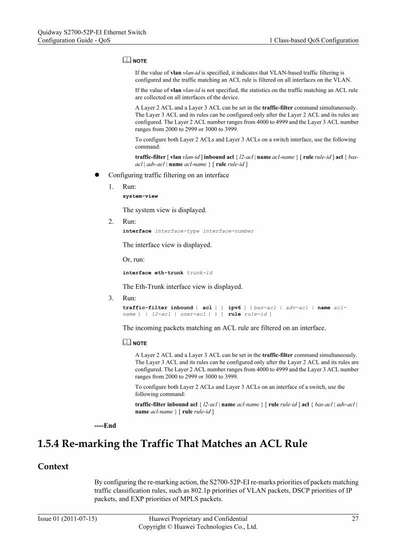
traffic-filter [ vlan vlan-id ] inbound { acl { [ ipv6 ] { bas-acl | adv-acl | name acl-name } | l2-acl | user-acl } [ rule rule-id ] }
The incoming packets matching an ACL rule are filtered on an interface.
Quidway S2700-52P-EI Ethernet SwitchConfiguration Guide - QoS 1 Class-based QoS Configuration
Issue 01 (2011-07-15) Huawei Proprietary and ConfidentialCopyright © Huawei Technologies Co., Ltd.
26
NOTE
If the value of vlan vlan-id is specified, it indicates that VLAN-based traffic filtering isconfigured and the traffic matching an ACL rule is filtered on all interfaces on the VLAN.
If the value of vlan vlan-id is not specified, the statistics on the traffic matching an ACL ruleare collected on all interfaces of the device.
A Layer 2 ACL and a Layer 3 ACL can be set in the traffic-filter command simultaneously.The Layer 3 ACL and its rules can be configured only after the Layer 2 ACL and its rules areconfigured. The Layer 2 ACL number ranges from 4000 to 4999 and the Layer 3 ACL numberranges from 2000 to 2999 or 3000 to 3999.
To configure both Layer 2 ACLs and Layer 3 ACLs on a switch interface, use the followingcommand:
traffic-filter [ vlan vlan-id ] inbound acl { l2-acl | name acl-name } [ rule rule-id ] acl { bas-acl | adv-acl | name acl-name } [ rule rule-id ]
l Configuring traffic filtering on an interface
1. Run:system-view
The system view is displayed.
2. Run:interface interface-type interface-number
The interface view is displayed.
Or, run:
interface eth-trunk trunk-id
The Eth-Trunk interface view is displayed.
3. Run:traffic-filter inbound { acl { [ ipv6 ] {bas-acl | adv-acl | name acl-name } | l2-acl | user-acl } } [ rule rule-id ]
The incoming packets matching an ACL rule are filtered on an interface.
NOTE
A Layer 2 ACL and a Layer 3 ACL can be set in the traffic-filter command simultaneously.The Layer 3 ACL and its rules can be configured only after the Layer 2 ACL and its rules areconfigured. The Layer 2 ACL number ranges from 4000 to 4999 and the Layer 3 ACL numberranges from 2000 to 2999 or 3000 to 3999.
To configure both Layer 2 ACLs and Layer 3 ACLs on an interface of a switch, use thefollowing command:
traffic-filter inbound acl { l2-acl | name acl-name } [ rule rule-id ] acl { bas-acl | adv-acl |name acl-name } [ rule rule-id ]
----End
1.5.4 Re-marking the Traffic That Matches an ACL Rule
Context
By configuring the re-marking action, the S2700-52P-EI re-marks priorities of packets matchingtraffic classification rules, such as 802.1p priorities of VLAN packets, DSCP priorities of IPpackets, and EXP priorities of MPLS packets.
Quidway S2700-52P-EI Ethernet SwitchConfiguration Guide - QoS 1 Class-based QoS Configuration
Issue 01 (2011-07-15) Huawei Proprietary and ConfidentialCopyright © Huawei Technologies Co., Ltd.
27
Procedurel Configuring re-marking globally
1. Run:system-view
The system view is displayed.2. Run:
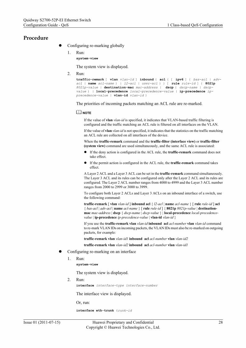
traffic-remark [ vlan vlan-id ] inbound { acl { [ ipv6 ] { bas-acl | adv-acl | name acl-name } | l2-acl | user-acl } } [ rule rule-id ] { 8021p 8021p-value | destination-mac mac-address | dscp { dscp-name | dscp-value } | local-precedence local-precedence-value | ip-precedence ip-precedence-value | vlan-id vlan-id }
The priorities of incoming packets matching an ACL rule are re-marked.
NOTE
If the value of vlan vlan-id is specified, it indicates that VLAN-based traffic filtering isconfigured and the traffic matching an ACL rule is filtered on all interfaces on the VLAN.
If the value of vlan vlan-id is not specified, it indicates that the statistics on the traffic matchingan ACL rule are collected on all interfaces of the device.
When the traffic-remark command and the traffic-filter (interface view) or traffic-filter(system view) command are used simultaneously, and the same ACL rule is associated:
l If the deny action is configured in the ACL rule, the traffic-remark command does nottake effect.
l If the permit action is configured in the ACL rule, the traffic-remark command takeseffect.
A Layer 2 ACL and a Layer 3 ACL can be set in the traffic-remark command simultaneously.The Layer 3 ACL and its rules can be configured only after the Layer 2 ACL and its rules areconfigured. The Layer 2 ACL number ranges from 4000 to 4999 and the Layer 3 ACL numberranges from 2000 to 2999 or 3000 to 3999.
To configure both Layer 2 ACLs and Layer 3 ACLs on an inbound interface of a switch, usethe following command:
traffic-remark [ vlan vlan-id ] inbound acl { l2-acl | name acl-name } [ rule rule-id ] acl{ bas-acl | adv-acl | name acl-name } [ rule rule-id ] { 8021p 8021p-value | destination-mac mac-address | dscp { dscp-name | dscp-value } | local-precedence local-precedence-value | ip-precedence ip-precedence-value | vlan-id vlan-id }
If you use the traffic-remark vlan vlan-id inbound acl acl-number vlan vlan-id commandto re-mark VLAN IDs on incoming packets, the VLAN IDs must also be re-marked on outgoingpackets, for example:
traffic-remark vlan vlan-id1 inbound acl acl-number vlan vlan-id2
traffic-remark vlan vlan-id2 inbound acl acl-number vlan vlan-id1
l Configuring re-marking on an interface1. Run:
system-view
The system view is displayed.2. Run:
interface interface-type interface-number
The interface view is displayed.
Or, run:
interface eth-trunk trunk-id
Quidway S2700-52P-EI Ethernet SwitchConfiguration Guide - QoS 1 Class-based QoS Configuration
Issue 01 (2011-07-15) Huawei Proprietary and ConfidentialCopyright © Huawei Technologies Co., Ltd.
28
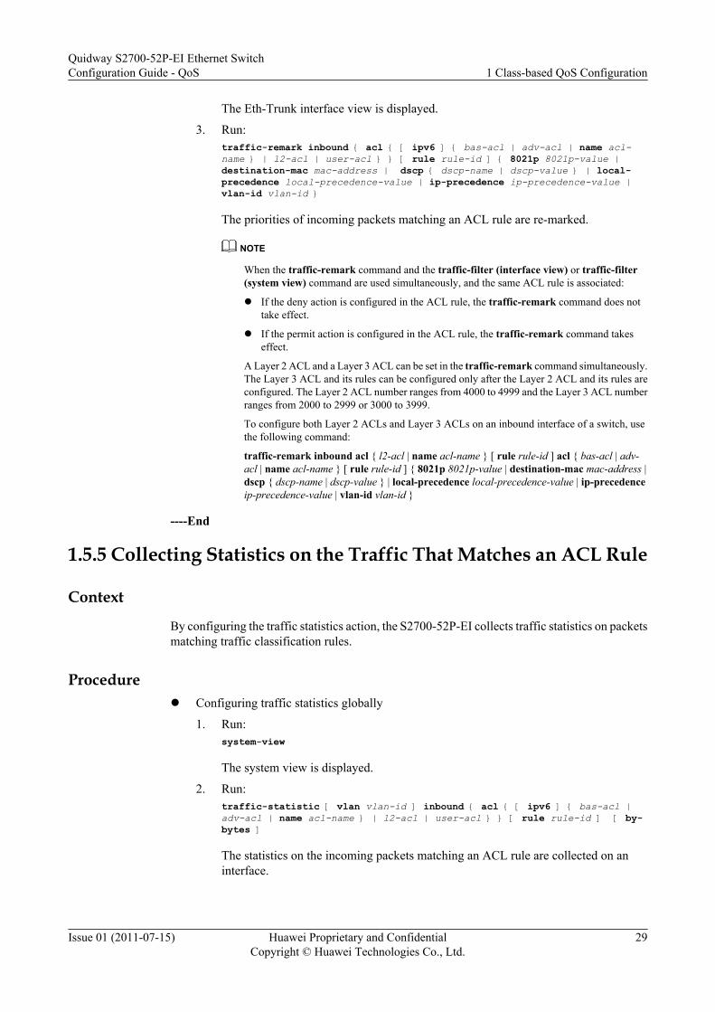
The Eth-Trunk interface view is displayed.
3. Run:traffic-remark inbound { acl { [ ipv6 ] { bas-acl | adv-acl | name acl-name } | l2-acl | user-acl } } [ rule rule-id ] { 8021p 8021p-value | destination-mac mac-address | dscp { dscp-name | dscp-value } | local-precedence local-precedence-value | ip-precedence ip-precedence-value | vlan-id vlan-id }
The priorities of incoming packets matching an ACL rule are re-marked.
NOTE
When the traffic-remark command and the traffic-filter (interface view) or traffic-filter(system view) command are used simultaneously, and the same ACL rule is associated:
l If the deny action is configured in the ACL rule, the traffic-remark command does nottake effect.
l If the permit action is configured in the ACL rule, the traffic-remark command takeseffect.
A Layer 2 ACL and a Layer 3 ACL can be set in the traffic-remark command simultaneously.The Layer 3 ACL and its rules can be configured only after the Layer 2 ACL and its rules areconfigured. The Layer 2 ACL number ranges from 4000 to 4999 and the Layer 3 ACL numberranges from 2000 to 2999 or 3000 to 3999.
To configure both Layer 2 ACLs and Layer 3 ACLs on an inbound interface of a switch, usethe following command:
traffic-remark inbound acl { l2-acl | name acl-name } [ rule rule-id ] acl { bas-acl | adv-acl | name acl-name } [ rule rule-id ] { 8021p 8021p-value | destination-mac mac-address |dscp { dscp-name | dscp-value } | local-precedence local-precedence-value | ip-precedenceip-precedence-value | vlan-id vlan-id }
----End
1.5.5 Collecting Statistics on the Traffic That Matches an ACL Rule
Context
By configuring the traffic statistics action, the S2700-52P-EI collects traffic statistics on packetsmatching traffic classification rules.
Procedurel Configuring traffic statistics globally
1. Run:system-view
The system view is displayed.
2. Run:traffic-statistic [ vlan vlan-id ] inbound { acl { [ ipv6 ] { bas-acl | adv-acl | name acl-name } | l2-acl | user-acl } } [ rule rule-id ] [ by-bytes ]
The statistics on the incoming packets matching an ACL rule are collected on aninterface.
Quidway S2700-52P-EI Ethernet SwitchConfiguration Guide - QoS 1 Class-based QoS Configuration
Issue 01 (2011-07-15) Huawei Proprietary and ConfidentialCopyright © Huawei Technologies Co., Ltd.
29

NOTE
If the value of vlan vlan-id is specified, it indicates that VLAN-based traffic filtering isconfigured and the traffic matching an ACL rule is filtered on all interfaces on the VLAN.
If the value of vlan vlan-id is not specified, the statistics on the traffic matching an ACL ruleare collected on all interfaces of the device.
A Layer 2 ACL and a Layer 3 ACL can be set in the traffic-statistic command simultaneously.The Layer 3 ACL and its rules can be configured only after the Layer 2 ACL and its rules areconfigured. The Layer 2 ACL number ranges from 4000 to 4999 and the Layer 3 ACL numberranges from 2000 to 2999 or 3000 to 3999.
To configure both Layer 2 ACLs and Layer 3 ACLs on an interface of a switch, use thefollowing command:
traffic-statistic [ vlan vlan-id ] inbound acl { l2-acl | name acl-name } [ rule rule-id ] acl{ bas-acl | adv-acl | name acl-name } [ rule rule-id ]
l Configuring traffic statistics on an interface
1. Run:system-view
The system view is displayed.
2. Run:interface interface-type interface-number
The interface view is displayed.
Or, run:
interface eth-trunk trunk-id
The Eth-Trunk interface view is displayed.
3. Run:traffic-statistic inbound acl { [ ipv6 ] { bas-acl | adv-acl | name acl-name } | l2-acl | user-acl } [ rule rule-id ] [ by-bytes ]
The statistics on the incoming packets matching an ACL rule are collected on aninterface.
NOTE
A Layer 2 ACL and a Layer 3 ACL can be set in the traffic-statistic command simultaneously.The Layer 3 ACL and its rules can be configured only after the Layer 2 ACL and its rules areconfigured. The Layer 2 ACL number ranges from 4000 to 4999 and the Layer 3 ACL numberranges from 2000 to 2999 or 3000 to 3999.
To configure both Layer 2 ACLs and Layer 3 ACLs on an interface of a switch, use thefollowing command:
traffic-statistic inbound acl { l2-acl | name acl-name } [ rule rule-id ] acl { bas-acl | adv-acl | name acl-name } [ rule rule-id ] [ by-bytes ]
----End
1.5.6 Redirecting the Traffic That Matches an ACL Rule
Context
By configuring the redirection action, the S2700-52P-EI redirects the packets matching trafficclassification rules to the CPU, the specified interface, or the specified next hop address.
Quidway S2700-52P-EI Ethernet SwitchConfiguration Guide - QoS 1 Class-based QoS Configuration
Issue 01 (2011-07-15) Huawei Proprietary and ConfidentialCopyright © Huawei Technologies Co., Ltd.
30
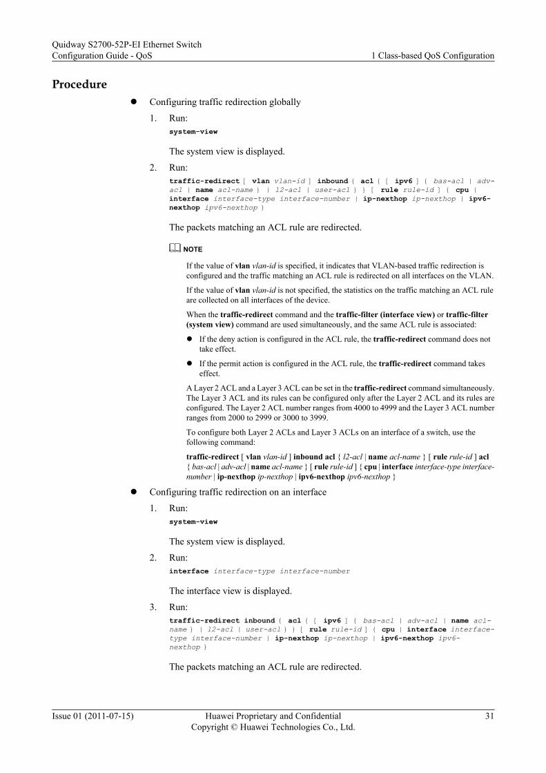
Procedurel Configuring traffic redirection globally
1. Run:system-view
The system view is displayed.
2. Run:traffic-redirect [ vlan vlan-id ] inbound { acl { [ ipv6 ] { bas-acl | adv-acl | name acl-name } | l2-acl | user-acl } } [ rule rule-id ] { cpu | interface interface-type interface-number | ip-nexthop ip-nexthop | ipv6-nexthop ipv6-nexthop }
The packets matching an ACL rule are redirected.
NOTE
If the value of vlan vlan-id is specified, it indicates that VLAN-based traffic redirection isconfigured and the traffic matching an ACL rule is redirected on all interfaces on the VLAN.
If the value of vlan vlan-id is not specified, the statistics on the traffic matching an ACL ruleare collected on all interfaces of the device.
When the traffic-redirect command and the traffic-filter (interface view) or traffic-filter(system view) command are used simultaneously, and the same ACL rule is associated:
l If the deny action is configured in the ACL rule, the traffic-redirect command does nottake effect.
l If the permit action is configured in the ACL rule, the traffic-redirect command takeseffect.
A Layer 2 ACL and a Layer 3 ACL can be set in the traffic-redirect command simultaneously.The Layer 3 ACL and its rules can be configured only after the Layer 2 ACL and its rules areconfigured. The Layer 2 ACL number ranges from 4000 to 4999 and the Layer 3 ACL numberranges from 2000 to 2999 or 3000 to 3999.
To configure both Layer 2 ACLs and Layer 3 ACLs on an interface of a switch, use thefollowing command:
traffic-redirect [ vlan vlan-id ] inbound acl { l2-acl | name acl-name } [ rule rule-id ] acl{ bas-acl | adv-acl | name acl-name } [ rule rule-id ] { cpu | interface interface-type interface-number | ip-nexthop ip-nexthop | ipv6-nexthop ipv6-nexthop }
l Configuring traffic redirection on an interface
1. Run:system-view
The system view is displayed.
2. Run:interface interface-type interface-number
The interface view is displayed.
3. Run:traffic-redirect inbound { acl { [ ipv6 ] { bas-acl | adv-acl | name acl-name } | l2-acl | user-acl } } [ rule rule-id ] { cpu | interface interface-type interface-number | ip-nexthop ip-nexthop | ipv6-nexthop ipv6-nexthop }
The packets matching an ACL rule are redirected.
Quidway S2700-52P-EI Ethernet SwitchConfiguration Guide - QoS 1 Class-based QoS Configuration
Issue 01 (2011-07-15) Huawei Proprietary and ConfidentialCopyright © Huawei Technologies Co., Ltd.
31

NOTE
A Layer 2 ACL and a Layer 3 ACL can be set in the traffic-redirect command simultaneously.The Layer 3 ACL and its rules can be configured only after the Layer 2 ACL and its rules areconfigured. The Layer 2 ACL number ranges from 4000 to 4999 and the Layer 3 ACL numberranges from 2000 to 2999 or 3000 to 3999.
To configure both Layer 2 ACLs and Layer 3 ACLs on an inbound interface of a switch, usethe following command:
traffic-redirect inbound acl { l2-acl | name acl-name } [ rule rule-id ] acl { bas-acl | adv-acl | name acl-name } [ rule rule-id ] { cpu | interface interface-type interface-number | ip-nexthop ip-nexthop | ipv6-nexthop ipv6-nexthop }
----End
1.6 Maintaining Class-based QoSIf the traffic statistics function is enabled, you can view and clear the flow-based traffic statistics.
1.6.1 Displaying the Flow-based Traffic StatisticsYou can use the display traffic policy statistics command to view the traffic statistics matchingthe specified traffic classification rule.
Context
To view the flow-based traffic statistics, a traffic policy must exist and contain the trafficstatistics action.
Procedurel Run the display traffic policy statistics { global [ slot slot-id ] | interface interface-type
interface-number | vlan vlan-id } inbound [ verbose { classifier-base | rule-base }[ class classifier-name ] ] command to check the flow-based traffic statistics.
----End
1.6.2 Clearing the Flow-based Traffic StatisticsYou can use the reset command to clear the flow-based traffic statistics.
Context
CAUTIONThe flow-based traffic statistics cannot be restored after being cleared. Exercise caution whenyou run the command.
Quidway S2700-52P-EI Ethernet SwitchConfiguration Guide - QoS 1 Class-based QoS Configuration
Issue 01 (2011-07-15) Huawei Proprietary and ConfidentialCopyright © Huawei Technologies Co., Ltd.
32

Procedurel Run the reset traffic policy statistics { global [ slot slot-id ] | interface interface-type
interface-number | vlan vlan-id } inbound command in the user view to clear the flow-based traffic statistics.
----End
1.7 Configuration ExamplesThis section provides several configuration examples of class-based QoS.
1.7.1 Example for Configuring Priority Mapping Based on SimpleTraffic Classification
After priority mapping based on simple traffic classification is configured, the S2700-52P-EImaps DSCP priorities of different user packets to new DSCP priorities to provide differentiatedservices.
Networking RequirementsAs shown in Figure 1-1, SwitchA and SwitchB are connected to the router, and branch 1 andbranch 2 of the enterprise can access the network through LSW1 and LSW2. Branch 1 requiresbetter QoS guarantee; therefore, the DSCP priority of data packets from branch 1 is mapped to45 and the DSCP priority of data packets from branch 2 is mapped to 30. The router trusts DSCPpriorities of packets. When congestion occurs, the router first processes packets of higher DSCPpriority.
Figure 1-1 Network diagram of priority mapping based on simple traffic classification
Core Network
Router
branch 1 of the enterprise
VLAN 100 VLAN 200
LSW1 LSW2
SwitchA SwitchB
GE0/0/1
GE0/0/2 GE0/0/2
GE0/0/1
branch 2 of the enterprise
Quidway S2700-52P-EI Ethernet SwitchConfiguration Guide - QoS 1 Class-based QoS Configuration
Issue 01 (2011-07-15) Huawei Proprietary and ConfidentialCopyright © Huawei Technologies Co., Ltd.
33
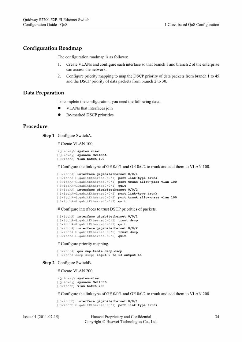
Configuration RoadmapThe configuration roadmap is as follows:
1. Create VLANs and configure each interface so that branch 1 and branch 2 of the enterprisecan access the network.
2. Configure priority mapping to map the DSCP priority of data packets from branch 1 to 45and the DSCP priority of data packets from branch 2 to 30.
Data PreparationTo complete the configuration, you need the following data:l VLANs that interfaces joinl Re-marked DSCP priorities
ProcedureStep 1 Configure SwitchA.
# Create VLAN 100.<Quidway> system-view[Quidway] sysname SwitchA[SwitchA] vlan batch 100
# Configure the link type of GE 0/0/1 and GE 0/0/2 to trunk and add them to VLAN 100.[SwitchA] interface gigabitethernet 0/0/1[SwitchA-GigabitEthernet0/0/1] port link-type trunk[SwitchA-GigabitEthernet0/0/1] port trunk allow-pass vlan 100[SwitchA-GigabitEthernet0/0/1] quit[SwitchA] interface gigabitethernet 0/0/2[SwitchA-GigabitEthernet0/0/2] port link-type trunk[SwitchA-GigabitEthernet0/0/2] port trunk allow-pass vlan 100[SwitchA-GigabitEthernet0/0/2] quit
# Configure interfaces to trust DSCP priorities of packets.[SwitchA] interface gigabitethernet 0/0/1[SwitchA-GigabitEthernet0/0/1] trust dscp[SwitchA-GigabitEthernet0/0/1] quit[SwitchA] interface gigabitethernet 0/0/2[SwitchA-GigabitEthernet0/0/2] trust dscp[SwitchA-GigabitEthernet0/0/2] quit
# Configure priority mapping.[SwitchA] qos map-table dscp-dscp[SwitchA-dscp-dscp] input 0 to 63 output 45
Step 2 Configure SwitchB.
# Create VLAN 200.<Quidway> system-view[Quidway] sysname SwitchB[SwitchB] vlan batch 200
# Configure the link type of GE 0/0/1 and GE 0/0/2 to trunk and add them to VLAN 200.[SwitchB] interface gigabitethernet 0/0/1[SwitchB-GigabitEthernet0/0/1] port link-type trunk
Quidway S2700-52P-EI Ethernet SwitchConfiguration Guide - QoS 1 Class-based QoS Configuration
Issue 01 (2011-07-15) Huawei Proprietary and ConfidentialCopyright © Huawei Technologies Co., Ltd.
34
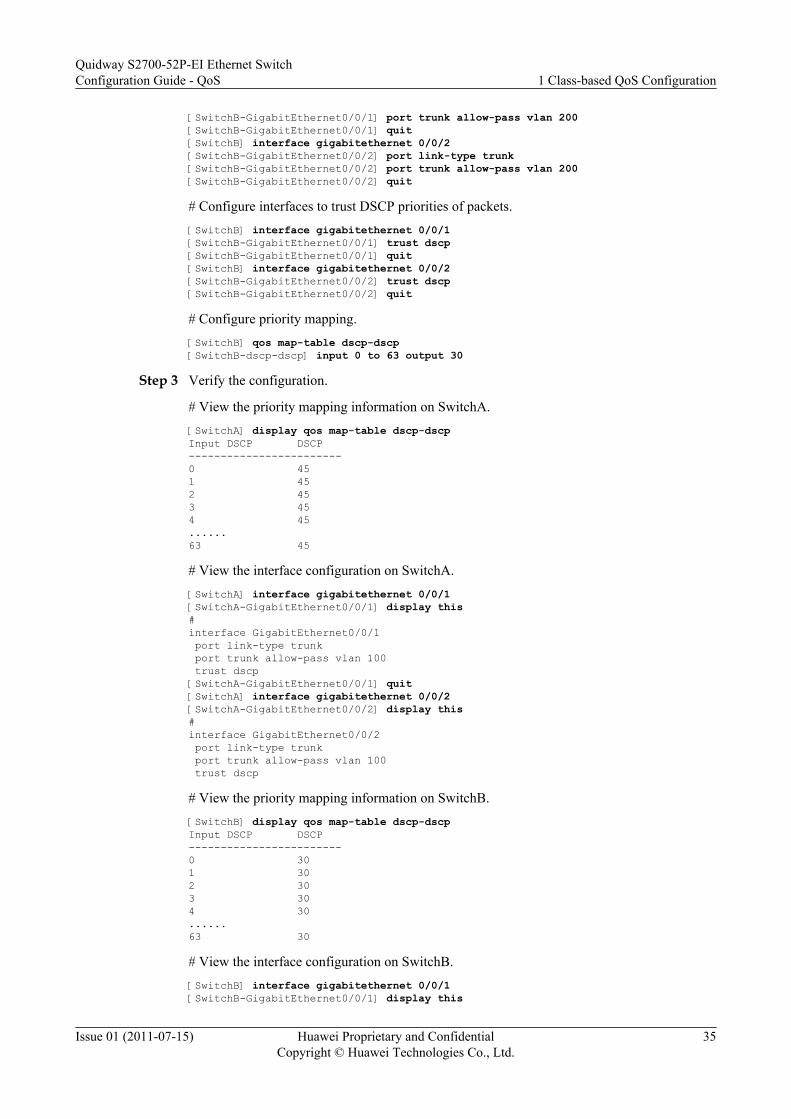
[SwitchB-GigabitEthernet0/0/1] port trunk allow-pass vlan 200[SwitchB-GigabitEthernet0/0/1] quit[SwitchB] interface gigabitethernet 0/0/2[SwitchB-GigabitEthernet0/0/2] port link-type trunk[SwitchB-GigabitEthernet0/0/2] port trunk allow-pass vlan 200[SwitchB-GigabitEthernet0/0/2] quit
# Configure interfaces to trust DSCP priorities of packets.[SwitchB] interface gigabitethernet 0/0/1[SwitchB-GigabitEthernet0/0/1] trust dscp[SwitchB-GigabitEthernet0/0/1] quit[SwitchB] interface gigabitethernet 0/0/2[SwitchB-GigabitEthernet0/0/2] trust dscp[SwitchB-GigabitEthernet0/0/2] quit
# Configure priority mapping.[SwitchB] qos map-table dscp-dscp[SwitchB-dscp-dscp] input 0 to 63 output 30
Step 3 Verify the configuration.
# View the priority mapping information on SwitchA.[SwitchA] display qos map-table dscp-dscpInput DSCP DSCP------------------------0 451 452 453 454 45......63 45
# View the interface configuration on SwitchA.[SwitchA] interface gigabitethernet 0/0/1[SwitchA-GigabitEthernet0/0/1] display this#interface GigabitEthernet0/0/1 port link-type trunk port trunk allow-pass vlan 100 trust dscp[SwitchA-GigabitEthernet0/0/1] quit[SwitchA] interface gigabitethernet 0/0/2[SwitchA-GigabitEthernet0/0/2] display this#interface GigabitEthernet0/0/2 port link-type trunk port trunk allow-pass vlan 100 trust dscp
# View the priority mapping information on SwitchB.[SwitchB] display qos map-table dscp-dscpInput DSCP DSCP------------------------0 301 302 303 304 30......63 30
# View the interface configuration on SwitchB.[SwitchB] interface gigabitethernet 0/0/1[SwitchB-GigabitEthernet0/0/1] display this
Quidway S2700-52P-EI Ethernet SwitchConfiguration Guide - QoS 1 Class-based QoS Configuration
Issue 01 (2011-07-15) Huawei Proprietary and ConfidentialCopyright © Huawei Technologies Co., Ltd.
35

#interface GigabitEthernet0/0/1 port link-type trunk port trunk allow-pass vlan 200 trust dscp[SwitchB-GigabitEthernet0/0/1] quit[SwitchB] interface gigabitethernet 0/0/2[SwitchB-GigabitEthernet0/0/2] display this#interface GigabitEthernet0/0/2 port link-type trunk port trunk allow-pass vlan 200 trust dscp
----End
Configuration Filesl Configuration file of SwitchA
# sysname SwitchA# vlan batch 100# interface GigabitEthernet0/0/1 port link-type trunk port trunk allow-pass vlan 100 trust dscp# interface GigabitEthernet0/0/2 port link-type trunk port trunk allow-pass vlan 100 trust dscp#qos map-table dscp-dscp input 0 to 44 output 45 input 46 to 63 output 45
l Configuration file of SwitchB# sysname SwitchB# vlan batch 200# interface GigabitEthernet0/0/1 port link-type trunk port trunk allow-pass vlan 200 trust dscp# interface GigabitEthernet0/0/2 port link-type trunk port trunk allow-pass vlan 200 trust dscp#qos map-table dscp-dscp input 0 to 29 output 30 input 31 to 63 output 30
1.7.2 Example for Re-marking the Priorities Based on ComplexTraffic Classification
After priority re-marking based on complex traffic classification is configured, the S2700-52P-EI adds the same outer VLAN ID to packets with different VLAN IDs. That is, these packetsare uniformly taken as the service data. In addition, the S2700-52P-EI re-marks different 802.1ppriorities of packets with different VLAN IDs to provide differentiated services.
Quidway S2700-52P-EI Ethernet SwitchConfiguration Guide - QoS 1 Class-based QoS Configuration
Issue 01 (2011-07-15) Huawei Proprietary and ConfidentialCopyright © Huawei Technologies Co., Ltd.
36

Networking Requirements
The Switch is connected to the router through GE 0/0/3; branch 1 and branch 2 of the enterprisecan access the network through the Switch and router. See Figure 1-2.
Data services of branch 1 and branch 2 of the enterprise come from VLANs 100 and 200. Whenthe data service packets of branch 1 and branch 2 of the enterprise pass the Switch, the Switchneeds to add the outer VLAN tag with the VLAN 300 to the packets so that these packets areidentified as data services on the Core network. In addition, branch 1 require better QoSguarantee; therefore, the priority of data packets to branch 1 is mapped to 4 and the priority ofdata packets to branch 2 is mapped to 2. By doing this, differentiated services are provided.
Figure 1-2 Networking diagram of priority re-marking based on complex traffic classification
CoreNetwork
GE0/0/1
GE0/0/3
Switch
Router
GE0/0/2VLAN 100 VLAN 200
Branch 1 of the enterprise
branch 2 of the enterprise
VLAN 300
Configuration Roadmap
The configuration roadmap is as follows:
1. Create VLANs and configure interfaces so that branch 1 and branch 2 of the enterprise canaccess the network through the Switch.
2. Create traffic classifiers based on the VLAN ID in the inner VLAN tag on the Switch.3. Create traffic behaviors on the Switch and re-mark 802.1p priorities of packets.4. Create a traffic policy on the Switch, bind traffic behaviors to traffic classifiers in the traffic
policy, and apply the traffic policy to the interface at the inbound direction.
Data Preparation
To complete the configuration, you need the following data:
Quidway S2700-52P-EI Ethernet SwitchConfiguration Guide - QoS 1 Class-based QoS Configuration
Issue 01 (2011-07-15) Huawei Proprietary and ConfidentialCopyright © Huawei Technologies Co., Ltd.
37
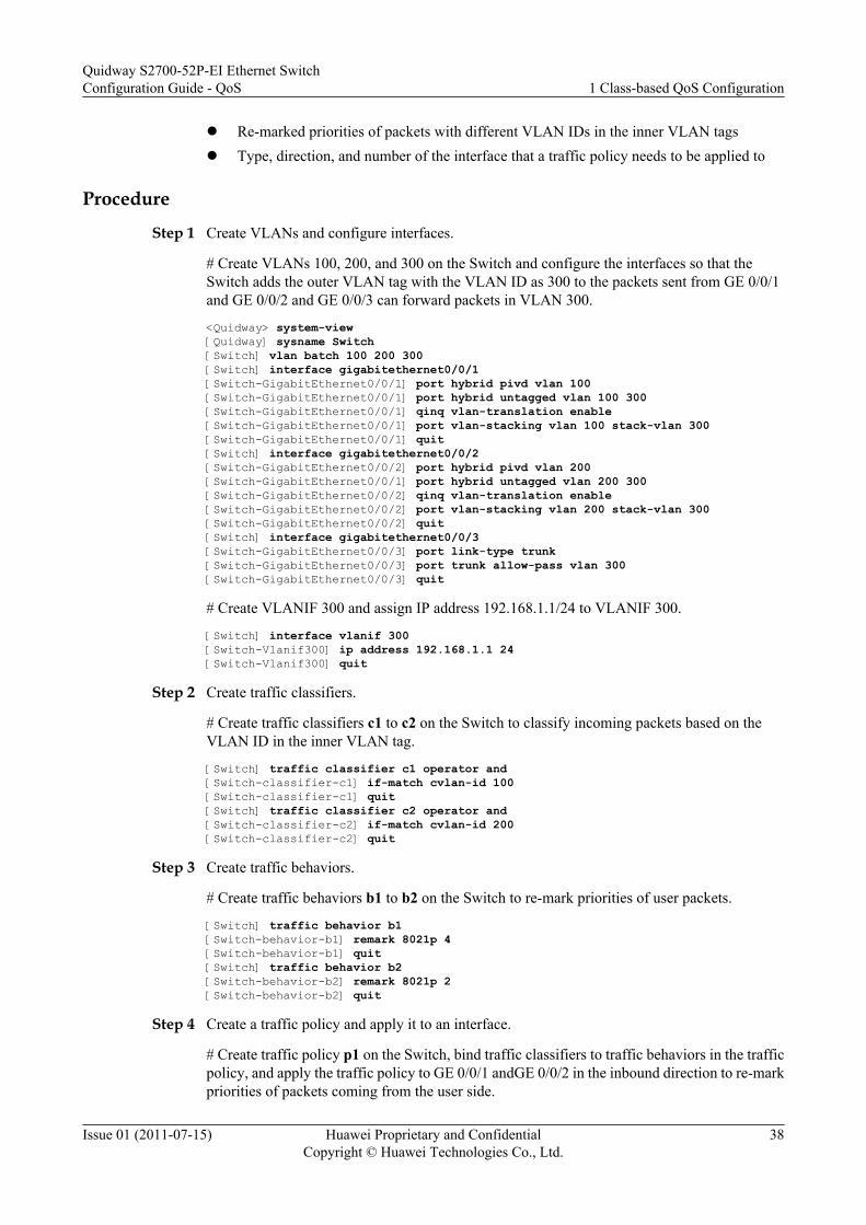
l Re-marked priorities of packets with different VLAN IDs in the inner VLAN tagsl Type, direction, and number of the interface that a traffic policy needs to be applied to
Procedure
Step 1 Create VLANs and configure interfaces.
# Create VLANs 100, 200, and 300 on the Switch and configure the interfaces so that theSwitch adds the outer VLAN tag with the VLAN ID as 300 to the packets sent from GE 0/0/1and GE 0/0/2 and GE 0/0/3 can forward packets in VLAN 300.
<Quidway> system-view[Quidway] sysname Switch[Switch] vlan batch 100 200 300[Switch] interface gigabitethernet0/0/1[Switch-GigabitEthernet0/0/1] port hybrid pivd vlan 100[Switch-GigabitEthernet0/0/1] port hybrid untagged vlan 100 300[Switch-GigabitEthernet0/0/1] qinq vlan-translation enable [Switch-GigabitEthernet0/0/1] port vlan-stacking vlan 100 stack-vlan 300[Switch-GigabitEthernet0/0/1] quit[Switch] interface gigabitethernet0/0/2[Switch-GigabitEthernet0/0/2] port hybrid pivd vlan 200[Switch-GigabitEthernet0/0/1] port hybrid untagged vlan 200 300[Switch-GigabitEthernet0/0/2] qinq vlan-translation enable [Switch-GigabitEthernet0/0/2] port vlan-stacking vlan 200 stack-vlan 300[Switch-GigabitEthernet0/0/2] quit[Switch] interface gigabitethernet0/0/3[Switch-GigabitEthernet0/0/3] port link-type trunk[Switch-GigabitEthernet0/0/3] port trunk allow-pass vlan 300[Switch-GigabitEthernet0/0/3] quit
# Create VLANIF 300 and assign IP address 192.168.1.1/24 to VLANIF 300.
[Switch] interface vlanif 300[Switch-Vlanif300] ip address 192.168.1.1 24[Switch-Vlanif300] quit
Step 2 Create traffic classifiers.
# Create traffic classifiers c1 to c2 on the Switch to classify incoming packets based on theVLAN ID in the inner VLAN tag.
[Switch] traffic classifier c1 operator and[Switch-classifier-c1] if-match cvlan-id 100[Switch-classifier-c1] quit[Switch] traffic classifier c2 operator and[Switch-classifier-c2] if-match cvlan-id 200[Switch-classifier-c2] quit
Step 3 Create traffic behaviors.
# Create traffic behaviors b1 to b2 on the Switch to re-mark priorities of user packets.
[Switch] traffic behavior b1[Switch-behavior-b1] remark 8021p 4[Switch-behavior-b1] quit[Switch] traffic behavior b2[Switch-behavior-b2] remark 8021p 2[Switch-behavior-b2] quit
Step 4 Create a traffic policy and apply it to an interface.
# Create traffic policy p1 on the Switch, bind traffic classifiers to traffic behaviors in the trafficpolicy, and apply the traffic policy to GE 0/0/1 andGE 0/0/2 in the inbound direction to re-markpriorities of packets coming from the user side.
Quidway S2700-52P-EI Ethernet SwitchConfiguration Guide - QoS 1 Class-based QoS Configuration
Issue 01 (2011-07-15) Huawei Proprietary and ConfidentialCopyright © Huawei Technologies Co., Ltd.
38
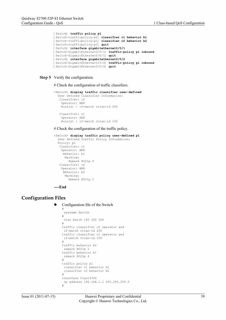
[Switch] traffic policy p1[Switch-trafficpolicy-p1] classifier c1 behavior b1[Switch-trafficpolicy-p1] classifier c2 behavior b2[Switch-trafficpolicy-p1] quit[Switch] interface gigabitethernet0/0/1[Switch-GigabitEthernet0/0/1] traffic-policy p1 inbound[Switch-GigabitEthernet0/0/1] quit[Switch] interface gigabitethernet0/0/2[Switch-GigabitEthernet0/0/2] traffic-policy p1 inbound[Switch-GigabitEthernet0/0/2] quit
Step 5 Verify the configuration.
# Check the configuration of traffic classifiers.
<Switch> display traffic classifier user-defined User Defined Classifier Information: Classifier: c2 Operator: AND Rule(s) : if-match cvlan-id 200
Classifier: c1 Operator: AND Rule(s) : if-match cvlan-id 100
# Check the configuration of the traffic policy.
<Switch> display traffic policy user-defined p1 User Defined Traffic Policy Information: Policy: p1 Classifier: c1 Operator: AND Behavior: b1 Marking: Remark 8021p 4 Classifier: c2 Operator: AND Behavior: b2 Marking: Remark 8021p 2
----End
Configuration Filesl Configuration file of the Switch
# sysname Switch# vlan batch 100 200 300#traffic classifier c2 operator and if-match cvlan-id 200traffic classifier c1 operator and if-match cvlan-id 100#traffic behavior b2 remark 8021p 2traffic behavior b1 remark 8021p 4#traffic policy p1 classifier c1 behavior b1 classifier c2 behavior b2#interface Vlanif300 ip address 192.168.1.1 255.255.255.0#
Quidway S2700-52P-EI Ethernet SwitchConfiguration Guide - QoS 1 Class-based QoS Configuration
Issue 01 (2011-07-15) Huawei Proprietary and ConfidentialCopyright © Huawei Technologies Co., Ltd.
39
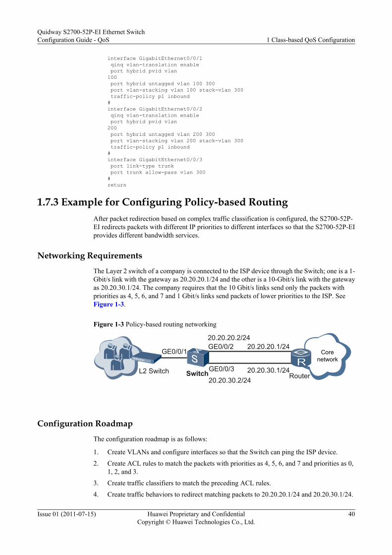
interface GigabitEthernet0/0/1 qinq vlan-translation enable port hybrid pvid vlan 100 port hybrid untagged vlan 100 300 port vlan-stacking vlan 100 stack-vlan 300 traffic-policy p1 inbound#interface GigabitEthernet0/0/2 qinq vlan-translation enable port hybrid pvid vlan 200 port hybrid untagged vlan 200 300 port vlan-stacking vlan 200 stack-vlan 300 traffic-policy p1 inbound#interface GigabitEthernet0/0/3 port link-type trunk port trunk allow-pass vlan 300#return
1.7.3 Example for Configuring Policy-based RoutingAfter packet redirection based on complex traffic classification is configured, the S2700-52P-EI redirects packets with different IP priorities to different interfaces so that the S2700-52P-EIprovides different bandwidth services.
Networking Requirements
The Layer 2 switch of a company is connected to the ISP device through the Switch; one is a 1-Gbit/s link with the gateway as 20.20.20.1/24 and the other is a 10-Gbit/s link with the gatewayas 20.20.30.1/24. The company requires that the 10 Gbit/s links send only the packets withpriorities as 4, 5, 6, and 7 and 1 Gbit/s links send packets of lower priorities to the ISP. SeeFigure 1-3.
Figure 1-3 Policy-based routing networking
GE0/0/1GE0/0/2
GE0/0/3
20.20.20.2/2420.20.20.1/24
20.20.30.2/2420.20.30.1/24L2 Switch Switch Router
Corenetwork
Configuration Roadmap
The configuration roadmap is as follows:
1. Create VLANs and configure interfaces so that the Switch can ping the ISP device.2. Create ACL rules to match the packets with priorities as 4, 5, 6, and 7 and priorities as 0,
1, 2, and 3.3. Create traffic classifiers to match the preceding ACL rules.4. Create traffic behaviors to redirect matching packets to 20.20.20.1/24 and 20.20.30.1/24.
Quidway S2700-52P-EI Ethernet SwitchConfiguration Guide - QoS 1 Class-based QoS Configuration
Issue 01 (2011-07-15) Huawei Proprietary and ConfidentialCopyright © Huawei Technologies Co., Ltd.
40

5. Create a traffic policy, bind traffic classifiers to traffic behaviors in the traffic policy, andapply the traffic policy to an interface.
Data PreparationTo complete the configuration, you need the following data:l VLAN 20 and VLAN 30 that all of GE0/0/1, GE0/0/2 and GE0/0/3 are added tol ACL rules 3001 and 3002l Traffic classifiers c1 and c2l Traffic behaviors b1 and b2l Traffic policy p1
Procedure
Step 1 Create VLANs and configure interfaces.
# Create VLANs 20 and 30.
<Quidway> system-view[Quidway] sysname Switch[Switch] vlan batch 20 30
# Configure the type of GE 0/0/1, GE 0/0/2 and GE 0/0/3 to trunk, and add all of GE 0/0/1,GE 0/0/2 and GE 0/0/3 to VLAN 20 and VLAN 30.
[Switch] interface gigabitethernet0/0/1[Switch-GigabitEthernet0/0/1] port link-type trunk[Switch-GigabitEthernet0/0/1] port trunk allow-pass vlan 20 30[Switch-GigabitEthernet0/0/1] quit[Switch] interface gigabitethernet0/0/2[Switch-GigabitEthernet0/0/2] port link-type trunk[Switch-GigabitEthernet0/0/2] port trunk allow-pass vlan 20 30[Switch-GigabitEthernet0/0/2] quit[Switch] interface gigabitethernet0/0/3[Switch-GigabitEthernet0/0/3] port link-type trunk[Switch-GigabitEthernet0/0/3] port trunk allow-pass vlan 20 30[Switch-GigabitEthernet0/0/3] quit
# Create VLANIF 20 and VLANIF 30 and assign IP addresses to them.
[Switch] interface vlanif 20[Switch-Vlanif20] ip address 20.20.20.2 24[Switch-Vlanif20] quit[Switch] interface vlanif 30[Switch-Vlanif30] ip address 20.20.30.2 24[Switch-Vlanif30] quit
NOTE
Assign network segment addresses 20.20.20.1/24 and 20.20.30.1/24 to the interfaces connecting the routerand Switch. The details are not mentioned here.
Step 2 Create ACL rules.
# Create advanced ACL rules 3001 and 3002 on the Switch to permit the packets with prioritiesas 4, 5, 6, and 7 and priorities as 0, 1, 2, and 3 to pass through.
[Switch] acl 3001[Switch-acl-adv-3001] rule permit ip precedence 0[Switch-acl-adv-3001] rule permit ip precedence 1[Switch-acl-adv-3001] rule permit ip precedence 2[Switch-acl-adv-3001] rule permit ip precedence 3[Switch-acl-adv-3001] quit
Quidway S2700-52P-EI Ethernet SwitchConfiguration Guide - QoS 1 Class-based QoS Configuration
Issue 01 (2011-07-15) Huawei Proprietary and ConfidentialCopyright © Huawei Technologies Co., Ltd.
41
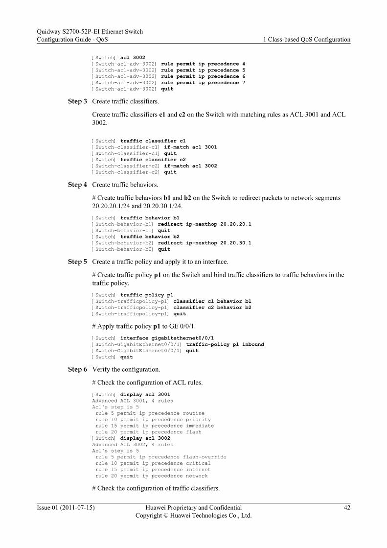
[Switch] acl 3002[Switch-acl-adv-3002] rule permit ip precedence 4[Switch-acl-adv-3002] rule permit ip precedence 5[Switch-acl-adv-3002] rule permit ip precedence 6[Switch-acl-adv-3002] rule permit ip precedence 7[Switch-acl-adv-3002] quit
Step 3 Create traffic classifiers.
Create traffic classifiers c1 and c2 on the Switch with matching rules as ACL 3001 and ACL3002.
[Switch] traffic classifier c1[Switch-classifier-c1] if-match acl 3001[Switch-classifier-c1] quit[Switch] traffic classifier c2[Switch-classifier-c2] if-match acl 3002[Switch-classifier-c2] quit
Step 4 Create traffic behaviors.
# Create traffic behaviors b1 and b2 on the Switch to redirect packets to network segments20.20.20.1/24 and 20.20.30.1/24.
[Switch] traffic behavior b1[Switch-behavior-b1] redirect ip-nexthop 20.20.20.1[Switch-behavior-b1] quit[Switch] traffic behavior b2[Switch-behavior-b2] redirect ip-nexthop 20.20.30.1[Switch-behavior-b2] quit
Step 5 Create a traffic policy and apply it to an interface.
# Create traffic policy p1 on the Switch and bind traffic classifiers to traffic behaviors in thetraffic policy.
[Switch] traffic policy p1[Switch-trafficpolicy-p1] classifier c1 behavior b1[Switch-trafficpolicy-p1] classifier c2 behavior b2[Switch-trafficpolicy-p1] quit
# Apply traffic policy p1 to GE 0/0/1.
[Switch] interface gigabitethernet0/0/1[Switch-GigabitEthernet0/0/1] traffic-policy p1 inbound[Switch-GigabitEthernet0/0/1] quit[Switch] quit
Step 6 Verify the configuration.
# Check the configuration of ACL rules.
[Switch] display acl 3001Advanced ACL 3001, 4 rulesAcl's step is 5 rule 5 permit ip precedence routine rule 10 permit ip precedence priority rule 15 permit ip precedence immediate rule 20 permit ip precedence flash [Switch] display acl 3002Advanced ACL 3002, 4 rulesAcl's step is 5 rule 5 permit ip precedence flash-override rule 10 permit ip precedence critical rule 15 permit ip precedence internet rule 20 permit ip precedence network
# Check the configuration of traffic classifiers.
Quidway S2700-52P-EI Ethernet SwitchConfiguration Guide - QoS 1 Class-based QoS Configuration
Issue 01 (2011-07-15) Huawei Proprietary and ConfidentialCopyright © Huawei Technologies Co., Ltd.
42

[Switch] display traffic classifier user-defined User Defined Classifier Information: Classifier: c2 Operator: AND Rule(s) : if-match acl 3002
Classifier: c1 Operator: AND Rule(s) : if-match acl 3001
Total classifier number is 2
# View the configuration of the traffic policy.
<Switch> display traffic policy user-defined p1 User Defined Traffic Policy Information: Policy: p1 Classifier: c1 Operator: AND Behavior: b1 Redirect: Redirect ip-nexthop 20.20.20.1 Classifier: c2 Operator: AND Behavior: b2 Redirect: Redirect ip-nexthop 20.20.30.1
----End
Configuration Filesl Configuration file of the Switch
# sysname Switch# vlan batch 20 30#acl number 3001 rule 5 permit ip precedence routine rule 10 permit ip precedence priority rule 15 permit ip precedence immediate rule 20 permit ip precedence flash#acl number 3002 rule 5 permit ip precedence flash-override rule 10 permit ip precedence critical rule 15 permit ip precedence internet rule 20 permit ip precedence network#traffic classifier c1 operator and if-match acl 3001traffic classifier c2 operator and if-match acl 3002#traffic behavior b1 redirect ip-nexthop 20.20.20.1traffic behavior b2 redirect ip-nexthop 20.20.30.1#traffic policy p1 classifier c1 behavior b1 classifier c2 behavior b2#interface Vlanif20 ip address 20.20.20.2 255.255.255.0
Quidway S2700-52P-EI Ethernet SwitchConfiguration Guide - QoS 1 Class-based QoS Configuration
Issue 01 (2011-07-15) Huawei Proprietary and ConfidentialCopyright © Huawei Technologies Co., Ltd.
43

#interface Vlanif30 ip address 20.20.30.2 255.255.255.0interface GigabitEthernet0/0/1 port link-type trunk port trunk allow-pass vlan 20 30 traffic-policy p1 inbound#interface GigabitEthernet0/0/2 port link-type trunk port trunk allow-pass vlan 20 30#interface GigabitEthernet0/0/3 port link-type trunk port trunk allow-pass vlan 20 30#return
1.7.4 Example for Configuring Traffic Statistics Based on ComplexTraffic Classification
After traffic statistics based on complex traffic classification is configured, the S2700-52P-EIcollect traffic statistics on packets with the specified source MAC address.
Networking RequirementsPC1 with the MAC address as 0000-0000-0003 is connected to other devices throughEth0/0/1 on the Switch. It is required that the Switch should take the statistics on the packetswith the source MAC address as 0000-0000-0003. See Figure 1-4.
Figure 1-4 Networking diagram for configuring traffic statistics based on complex trafficclassification
Core Network
SwitchPC1 Router
MAC:0000-0000-0003
Eth0/0/1 GE0/0/2
VLANIF 2020.20.20.1/24
20.20.20.2/24
Configuration RoadmapThe configuration roadmap is as follows:
1. Configure interfaces so that the Switch is connected to PC1 and the router.2. Create an ACL to match the packets with the source MAC address as 0000-0000-0003.3. Create a traffic classifier to match the ACL.4. Create a traffic behavior to take the statistics on the matching packets.5. Create a traffic policy, bind the traffic classifier to the traffic behavior in the traffic policy,
and apply the traffic policy to Eth0/0/1 in the inbound direction.
Data PreparationTo complete the configuration, you need the following data:
Quidway S2700-52P-EI Ethernet SwitchConfiguration Guide - QoS 1 Class-based QoS Configuration
Issue 01 (2011-07-15) Huawei Proprietary and ConfidentialCopyright © Huawei Technologies Co., Ltd.
44
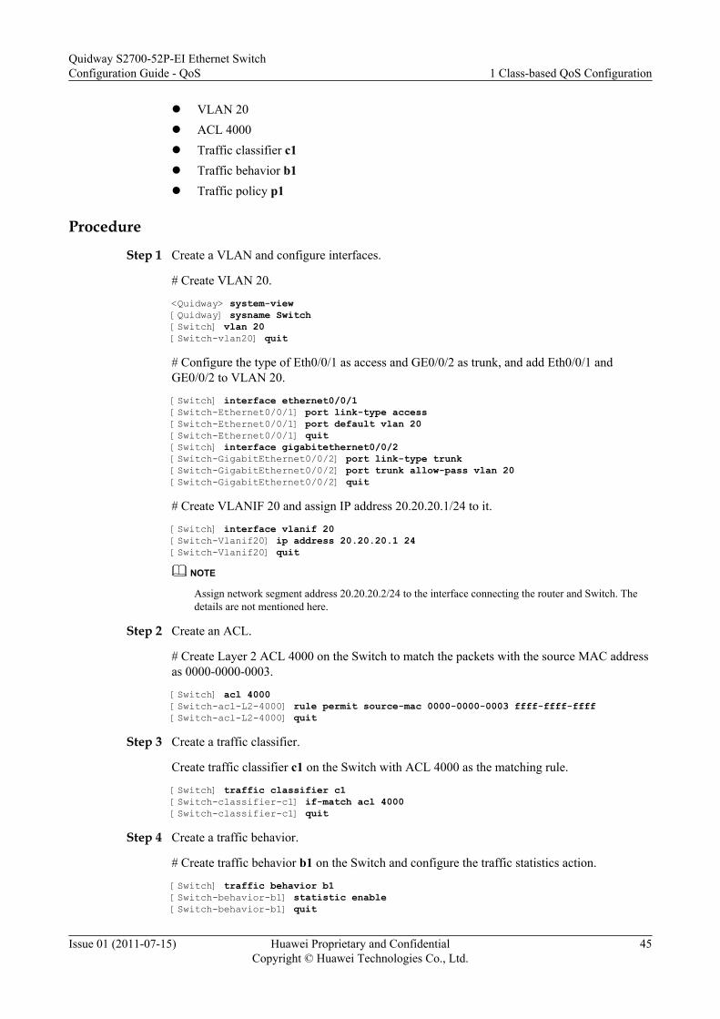
l VLAN 20l ACL 4000l Traffic classifier c1l Traffic behavior b1l Traffic policy p1
Procedure
Step 1 Create a VLAN and configure interfaces.
# Create VLAN 20.
<Quidway> system-view[Quidway] sysname Switch[Switch] vlan 20[Switch-vlan20] quit
# Configure the type of Eth0/0/1 as access and GE0/0/2 as trunk, and add Eth0/0/1 andGE0/0/2 to VLAN 20.
[Switch] interface ethernet0/0/1[Switch-Ethernet0/0/1] port link-type access[Switch-Ethernet0/0/1] port default vlan 20[Switch-Ethernet0/0/1] quit[Switch] interface gigabitethernet0/0/2[Switch-GigabitEthernet0/0/2] port link-type trunk[Switch-GigabitEthernet0/0/2] port trunk allow-pass vlan 20[Switch-GigabitEthernet0/0/2] quit
# Create VLANIF 20 and assign IP address 20.20.20.1/24 to it.
[Switch] interface vlanif 20[Switch-Vlanif20] ip address 20.20.20.1 24[Switch-Vlanif20] quit
NOTE
Assign network segment address 20.20.20.2/24 to the interface connecting the router and Switch. Thedetails are not mentioned here.
Step 2 Create an ACL.
# Create Layer 2 ACL 4000 on the Switch to match the packets with the source MAC addressas 0000-0000-0003.
[Switch] acl 4000[Switch-acl-L2-4000] rule permit source-mac 0000-0000-0003 ffff-ffff-ffff[Switch-acl-L2-4000] quit
Step 3 Create a traffic classifier.
Create traffic classifier c1 on the Switch with ACL 4000 as the matching rule.
[Switch] traffic classifier c1[Switch-classifier-c1] if-match acl 4000[Switch-classifier-c1] quit
Step 4 Create a traffic behavior.
# Create traffic behavior b1 on the Switch and configure the traffic statistics action.
[Switch] traffic behavior b1[Switch-behavior-b1] statistic enable[Switch-behavior-b1] quit
Quidway S2700-52P-EI Ethernet SwitchConfiguration Guide - QoS 1 Class-based QoS Configuration
Issue 01 (2011-07-15) Huawei Proprietary and ConfidentialCopyright © Huawei Technologies Co., Ltd.
45
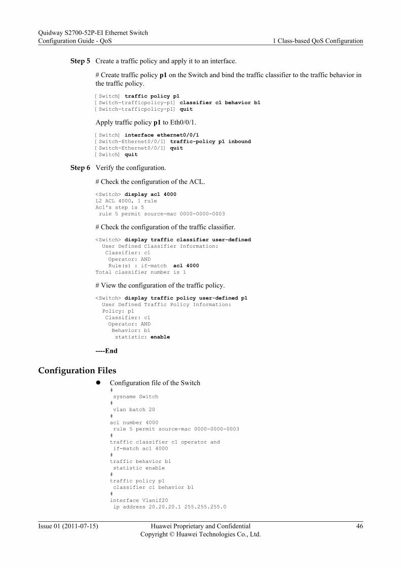
Step 5 Create a traffic policy and apply it to an interface.
# Create traffic policy p1 on the Switch and bind the traffic classifier to the traffic behavior inthe traffic policy.
[Switch] traffic policy p1[Switch-trafficpolicy-p1] classifier c1 behavior b1[Switch-trafficpolicy-p1] quit
Apply traffic policy p1 to Eth0/0/1.
[Switch] interface ethernet0/0/1[Switch-Ethernet0/0/1] traffic-policy p1 inbound[Switch-Ethernet0/0/1] quit[Switch] quit
Step 6 Verify the configuration.
# Check the configuration of the ACL.
<Switch> display acl 4000L2 ACL 4000, 1 ruleAcl's step is 5 rule 5 permit source-mac 0000-0000-0003
# Check the configuration of the traffic classifier.
<Switch> display traffic classifier user-defined User Defined Classifier Information: Classifier: c1 Operator: AND Rule(s) : if-match acl 4000Total classifier number is 1
# View the configuration of the traffic policy.
<Switch> display traffic policy user-defined p1 User Defined Traffic Policy Information: Policy: p1 Classifier: c1 Operator: AND Behavior: b1 statistic: enable
----End
Configuration Filesl Configuration file of the Switch
# sysname Switch# vlan batch 20#acl number 4000 rule 5 permit source-mac 0000-0000-0003 #traffic classifier c1 operator and if-match acl 4000#traffic behavior b1 statistic enable#traffic policy p1 classifier c1 behavior b1 #interface Vlanif20 ip address 20.20.20.1 255.255.255.0
Quidway S2700-52P-EI Ethernet SwitchConfiguration Guide - QoS 1 Class-based QoS Configuration
Issue 01 (2011-07-15) Huawei Proprietary and ConfidentialCopyright © Huawei Technologies Co., Ltd.
46

#interface Ethernet0/0/1 port link-type access port default vlan 20 traffic-policy p1 inbound#interface GigabitEthernet0/0/2 port link-type trunk port trunk allow-pass vlan 20#return
Quidway S2700-52P-EI Ethernet SwitchConfiguration Guide - QoS 1 Class-based QoS Configuration
Issue 01 (2011-07-15) Huawei Proprietary and ConfidentialCopyright © Huawei Technologies Co., Ltd.
47

2 Traffic Policing and Traffic ShapingConfiguration
About This Chapter
This document describes basic concepts of traffic policing and traffic shaping, and introducesthe configuration method of traffic policing based on a traffic classifier, and traffic shaping, andprovides configuration examples.
2.1 Overview of Traffic Policing and Traffic ShapingThis section describes the basic concepts of traffic policing and traffic shaping and thedifferences between traffic policing and traffic shaping.
2.2 Configuring Traffic Policing Based on an InterfaceAfter traffic policing based on an interface is configured, the S2700-52P-EI policies the trafficon the interface.
2.3 Configuring Traffic Policing Based on a Traffic ClassifierAfter traffic policing based on a traffic classifier is configured, the S2700-52P-EI policies thetraffic matching traffic classification rules.
2.4 Configuring Traffic ShapingAfter traffic shaping is configured, the S2700-52P-EI shapes packets matching trafficclassification rules so that packets are sent out at an even rate.
2.5 Maintaining Traffic Policing and Traffic ShapingThis section describes how to maintain traffic policing and traffic shaping.
2.6 Configuration ExamplesThis section provides several configuration examples of traffic policing and traffic shaping.
Quidway S2700-52P-EI Ethernet SwitchConfiguration Guide - QoS 2 Traffic Policing and Traffic Shaping Configuration
Issue 01 (2011-07-15) Huawei Proprietary and ConfidentialCopyright © Huawei Technologies Co., Ltd.
48

2.1 Overview of Traffic Policing and Traffic ShapingThis section describes the basic concepts of traffic policing and traffic shaping and thedifferences between traffic policing and traffic shaping.
2.1.1 Traffic PolicingTo make full use of limited network resources, perform traffic policing for special service flowsto adapt to the allocated network resources.
Traffic policing is a traffic control action used to limit the volume of traffic and the resourcesused by the traffic by monitoring the rate of the traffic.
Traffic policing controls traffic matching traffic classification rules and discards the excesstraffic, limiting traffic within a proper range and protecting network resources and carriers'interests.
Traffic policing is widely used to limit the volume of traffic entering Internet Service Provider(ISP) networks.
Token Bucket and Traffic MeasurementWhen the traffic exceeds the rate limit, the S2700-52P-EI uses traffic control policies. Generally,a token bucket is used to measure the volume of traffic.
A token bucket is considered as a container that stores a certain number of tokens. TheS2700-52P-EI puts tokens at the configured rate (one token bucket can forward one bit of data)in a token bucket. When the token bucket is full, the excess tokens overflow and the number oftokens no longer increases.
When measuring the traffic in a token bucket, the S2700-52P-EI forwards packets based on thenumber of tokens in the token bucket. If there are sufficient tokens in the token bucket to forwardpackets, the traffic rate is within the rate limit. Otherwise, the traffic rate exceeds the rate limit.
Figure 2-1 Using a token bucket to measure the traffic
Packets that need to besent from this interface
Continue to send
Tokenbucket
Put tokens into the bucket atthe set rate
Classification
Drop
Quidway S2700-52P-EI Ethernet SwitchConfiguration Guide - QoS 2 Traffic Policing and Traffic Shaping Configuration
Issue 01 (2011-07-15) Huawei Proprietary and ConfidentialCopyright © Huawei Technologies Co., Ltd.
49

The S2700-52P-EI supports the single token bucket and dual token buckets.
l Single token bucketThe single token bucket technology uses the following parameters:– Committed burst size (CBS): indicates the maximum volume of traffic that bursts in
bucket C, in bytes.– Committed information rate (CIR): indicates the rate of tokens that are put into bucket
C, that is, the average traffic rate allowed by bucket C, in kbit/s.If there are sufficient tokens in the bucket, packets are forwarded. At the same time, thenumber of tokens in the bucket decreases based on the length of the packets. If there areno tokens in the bucket, packets are discarded.
l Dual token bucketsThe dual token bucket technology uses the following parameters in addition to the CIR andCBS:– Peak burst size (PBS): indicates the maximum volume of traffic that bursts and exceeds
the CBS in bucket P, in bytes.– Peak information rate (PIR): indicates the rate of tokens that are put into bucket P, that
is, the average traffic rate allowed by bucket P, in kbit/s.For the dual token buckets:– The service traffic that less than the CIR value is colored green and is allowed to pass
through.– The service traffic that exceeds the PIR value is colored red and is discarded.– The service traffic that ranges from the CIR value to the PIR value is colored yellow
and is discarded when congestion occurs.
Traffic Policing Features Supported by the S2700-52P-EIThe S2700-52P-EI supports the following traffic policing features:
l Interface-based traffic policing.Interface-based traffic policing controls all incoming traffic on an interface regardless ofpacket types and discards the excess traffic, limiting traffic within a proper range andprotecting network resources and carriers' interests.
l Traffic policing based on a traffic classifierTraffic policing based on a traffic classifier limits the rate of the traffic matching a trafficclassifier after traffic classification is performed on the S2700-52P-EI. The S2700-52P-EI limits the rate of incoming traffic and discards the traffic that exceeds the rate limit,limiting traffic within a proper range and protecting network resources and carriers'interests. Traffic policing based on a traffic classifier uses dual token buckets.
2.1.2 Traffic ShapingThe traffic shaping function is used to control the rate of packets so that packets are sent at aneven rate. Traffic shaping is used to adapt the transmission rate of packets to the downstreamdevices to prevent unnecessary packet loss and congestion.
Traffic shaping is a traffic control action used to limit traffic and resources by monitoring thespecification of the traffic. In traffic shaping, token buckets are also used to measure the traffic.
Quidway S2700-52P-EI Ethernet SwitchConfiguration Guide - QoS 2 Traffic Policing and Traffic Shaping Configuration
Issue 01 (2011-07-15) Huawei Proprietary and ConfidentialCopyright © Huawei Technologies Co., Ltd.
50
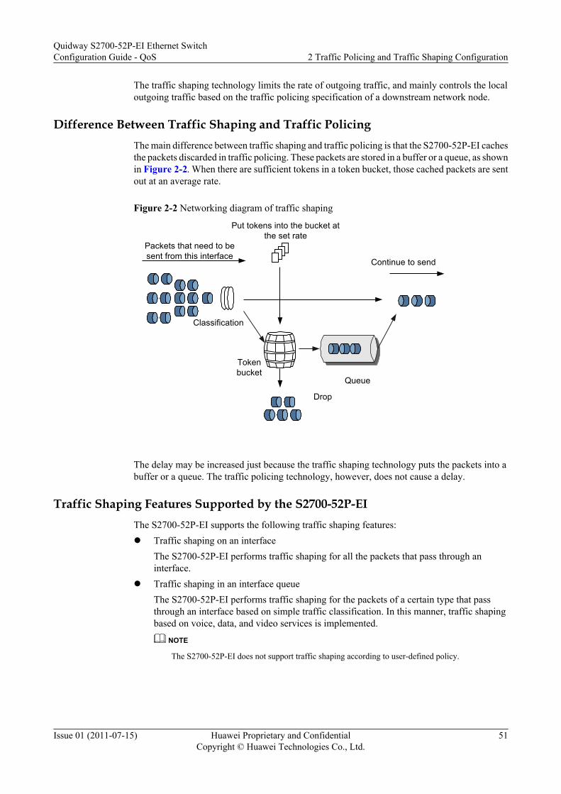
The traffic shaping technology limits the rate of outgoing traffic, and mainly controls the localoutgoing traffic based on the traffic policing specification of a downstream network node.
Difference Between Traffic Shaping and Traffic PolicingThe main difference between traffic shaping and traffic policing is that the S2700-52P-EI cachesthe packets discarded in traffic policing. These packets are stored in a buffer or a queue, as shownin Figure 2-2. When there are sufficient tokens in a token bucket, those cached packets are sentout at an average rate.
Figure 2-2 Networking diagram of traffic shaping
Packets that need to besent from this interface
Continue to send
Tokenbucket
Put tokens into the bucket atthe set rate
Classification
Drop
Queue
The delay may be increased just because the traffic shaping technology puts the packets into abuffer or a queue. The traffic policing technology, however, does not cause a delay.
Traffic Shaping Features Supported by the S2700-52P-EIThe S2700-52P-EI supports the following traffic shaping features:l Traffic shaping on an interface
The S2700-52P-EI performs traffic shaping for all the packets that pass through aninterface.
l Traffic shaping in an interface queueThe S2700-52P-EI performs traffic shaping for the packets of a certain type that passthrough an interface based on simple traffic classification. In this manner, traffic shapingbased on voice, data, and video services is implemented.
NOTE
The S2700-52P-EI does not support traffic shaping according to user-defined policy.
Quidway S2700-52P-EI Ethernet SwitchConfiguration Guide - QoS 2 Traffic Policing and Traffic Shaping Configuration
Issue 01 (2011-07-15) Huawei Proprietary and ConfidentialCopyright © Huawei Technologies Co., Ltd.
51
2.2 Configuring Traffic Policing Based on an InterfaceAfter traffic policing based on an interface is configured, the S2700-52P-EI policies the trafficon the interface.
2.2.1 Establishing the Configuration TaskBefore configuring traffic policing based on an interface, familiarize yourself with the applicableenvironment, complete the pre-configuration tasks, and obtain the required data. This helps youcomplete the configuration task quickly and accurately.
Applicable EnvironmentIf the service traffic sent by users is not limited, a large amount of increasing burst service datamakes a network more congested. To make full use of network resources and provide betterservices for more users, you must limit user service traffic. After interface-based traffic policingis applied to the interface, the rate of all the user service traffic entering the interface is limited.
Pre-configuration TasksBefore configuring a limit rate on the interface, complete the following tasks:l Setting physical parameters of interfacesl Setting link layer attributes of interfaces to ensure normal operation of these interfacesl Assigning IP addresses to the interfaces and configuring routing protocols to ensure that
routes are reachable
Data PreparationTo configure interface-based traffic policing, you need the following data.
No. Data
1 CIR and CBS
2 Interface where traffic policing is configured or queue index
2.2.2 Limiting the Rate of Traffic on the InterfaceTo limit the rate of traffic entering the S2700-52P-EI, configure traffic policing on the inboundinterface.
Procedure
Step 1 Run:system-view
The system view is displayed.
Quidway S2700-52P-EI Ethernet SwitchConfiguration Guide - QoS 2 Traffic Policing and Traffic Shaping Configuration
Issue 01 (2011-07-15) Huawei Proprietary and ConfidentialCopyright © Huawei Technologies Co., Ltd.
52

Step 2 Run:interface interface-type interface-number
The interface view is displayed.
Or, run:
port-group port-group-name
The port group view is displayed.
NOTE
You can configure interface-based traffic policing on Ethernet and GE interfaces.
To set the same QoS CAR parameters on multiple interfaces, perform the configuration on the port groupto reduce the workload.
You need to create a port group before performing this task. For details on how to create a port group, see(Optional) Configuring the Interface Group in the Quidway S2700-52P-EI Ethernet SwitchesConfiguration Guide - Ethernet.
Step 3 Run:qos lr { inbound | outbound } cir cir-value [ cbs cbs-value ]
Traffic policing is configured on the interface.
----End
2.2.3 Checking the ConfigurationAfter interface-based rate limit is configured, you can view rate limit information on theinterface.
Prerequisite
The configurations of interface-based rate limit are complete.
Procedurel Run the display qos lr { inbound | outbound } interface interface-type interface-
number command to view rate limit information on the interface.
l Run the display qos configuration interface [ interface-type interface-number ] commandto check all the QoS configuration on the interface.
----End
2.3 Configuring Traffic Policing Based on a TrafficClassifier
After traffic policing based on a traffic classifier is configured, the S2700-52P-EI policies thetraffic matching traffic classification rules.
Quidway S2700-52P-EI Ethernet SwitchConfiguration Guide - QoS 2 Traffic Policing and Traffic Shaping Configuration
Issue 01 (2011-07-15) Huawei Proprietary and ConfidentialCopyright © Huawei Technologies Co., Ltd.
53

2.3.1 Establishing the Configuration TaskBefore configuring traffic policing based on a traffic classifier, familiarize yourself with theapplicable environment, complete the pre-configuration tasks, and obtain the data required forthe configuration. This will help you complete the configuration task quickly and accurately.
Applicable Environment
If the service traffic sent by users is not limited, a network is congested because a large numberof users send bursts of data in the same period. To make full use of limited network resourcesand provide better services for more users, limit user service traffic.
Traffic policing based on a traffic classifier can be used to control the service traffic of a certaintype.
Pre-configuration Tasks
Before configuring traffic policing based on a traffic classifier, complete the following tasks:
l Setting physical parameters of interfaces
l Setting link layer attributes of interfaces to ensure that these interfaces work properly
l Assigning IP addresses to the interfaces and configuring routing protocols to ensure thatroutes are reachable
Data Preparation
To configure traffic policing based on a traffic classifier, you need the following data.
No. Data
1 Name of the traffic classifier and related parameters
2 Name of the traffic behavior and CAR parameters: CIR, (optional) CBS, (optional)PIR, (optional) PBS, (optional) color
3 Name of the traffic policy, and object and inbound or outbound direction to whichtraffic policing based on a traffic classifier is applied
2.3.2 Configuring Complex Traffic ClassificationThe S2700-52P-EI can classify traffic according to the ACL, Layer 2 information in packets,and Layer 3 information in packets.
Select proper traffic classification rules and configure complex traffic classification as required.For details, see 1.4.2 Configuring Complex Traffic Classification.
2.3.3 Configuring a Traffic Policing ActionYou can configure traffic policing actions, set CAR parameters of the CIR, CBS, PIR, and PBSvalues, and set actions for packets with different PHBs and colors.
Quidway S2700-52P-EI Ethernet SwitchConfiguration Guide - QoS 2 Traffic Policing and Traffic Shaping Configuration
Issue 01 (2011-07-15) Huawei Proprietary and ConfidentialCopyright © Huawei Technologies Co., Ltd.
54

ProcedureStep 1 Run:
system-view
The system view is displayed.
Step 2 Run:traffic behavior behavior-name
A traffic behavior is created and the traffic behavior view is displayed.
Step 3 Run the following command:car [ aggregation ] cir cir-value [ pir pir-value ] [ cbs cbs-value pbs pbs-value ] [ green { discard | pass [ remark-dscp dscp-value | remark-8021p 8021p-precedence ] } ] [ yellow { discard | pass [ remark-dscp dscp-value | remark-8021p 8021p-precedence ] } ] [ red { discard | pass [ remark-dscp dscp-value | remark-8021p 8021p-precedence ] } ]
The CAR is configured.
You can define the color of packets in traffic policing:
l When the burst size of a packet is smaller than the CBS value, the packet is colored green.l When the burst size of a packet is equal to or larger than the CBS value but smaller than the
PBS value, the packet is colored yellow.l When the burst size of a packet is equal to or larger than the PBS value, the packet is colored
red.NOTE
If you configure the CAR action multiple times in the same traffic behavior view, only the latestconfiguration takes effect.If aggregation is specified, when a traffic policy bound to the traffic behavior containing aggregate CARis applied to multiple interfaces, the system aggregates all the flows on the interfaces and applies the CARto the flows.
----End
2.3.4 Creating a Traffic PolicyYou can associate a traffic classifier with a traffic behavior in a traffic policy.
ProcedureStep 1 Run:
system-view
The system view is displayed.
Step 2 Run:traffic policy policy-name
A traffic policy is created and the traffic policy view is displayed.
Step 3 Run:classifier classifier-name behavior behavior-name
A traffic classifier is bound to a traffic behavior in the traffic policy.
----End
Quidway S2700-52P-EI Ethernet SwitchConfiguration Guide - QoS 2 Traffic Policing and Traffic Shaping Configuration
Issue 01 (2011-07-15) Huawei Proprietary and ConfidentialCopyright © Huawei Technologies Co., Ltd.
55

2.3.5 Applying the Traffic PolicyThe configured traffic policy takes effect only after it is applied to the system, an interface, ora VLAN.
Procedurel Applying a traffic policy to the system
1. Run:system-view
The system view is displayed.2. Run:
traffic-policy policy-name global inbound
A traffic policy is applied to the system.
Only one traffic policy can be applied to the system in the inbound direction.
After a traffic policy is applied, the system performs traffic policing for all the packetsthat match a traffic classifier in the inbound direction.
l Applying a traffic policy to an interface1. Run:
system-view
The system view is displayed.2. Run:
interface interface-type interface-number
The interface view is displayed.3. Run:
traffic-policy policy-name inbound
A traffic policy is applied to the interface
Only one traffic policy can be applied to an interface in the inbound direction.
After a traffic policy is applied, the system performs traffic policing for the packetsthat pass through this interface and match a traffic classifier in the inbound direction.
l Applying a traffic policy to a VLAN1. Run:
system-view
The system view is displayed.2. Run:
vlan vlan-id
The VLAN view is displayed.3. Run:
traffic-policy policy-name inbound
A traffic policy is applied to the VLAN.
Only one traffic policy can be applied to a VLAN in the inbound direction.
Quidway S2700-52P-EI Ethernet SwitchConfiguration Guide - QoS 2 Traffic Policing and Traffic Shaping Configuration
Issue 01 (2011-07-15) Huawei Proprietary and ConfidentialCopyright © Huawei Technologies Co., Ltd.
56

After a traffic policy is applied, the system performs traffic policing for the packetsthat belong to a VLAN and match a traffic classifier in the inbound direction.
----End
2.3.6 Checking the ConfigurationAfter traffic policing based on a traffic classifier is configured, you can view the traffic statisticsor CAR statistics.
ContextThe configurations of traffic policing based on a traffic classifier are complete.
Procedurel Run the display traffic behavior user-defined [ behavior-name ] command to check the
traffic behavior configuration.l Run the display traffic classifier user-defined [ classifier-name ] command to check the
traffic classifier configuration.l Run the display traffic policy user-defined [ policy-name [ classifier classifier-name ] ]
command to check the traffic policy configuration.l Run the display traffic policy { interface [ interface-type interface-number ] | vlan [ vlan-
id ] | global } [ inbound ] command to check the traffic policy information and flow-basedtraffic statistics.
l Run the display qos configuration interface [ interface-type interface-number ] commandto check all the QoS configurations on the interface.
----End
2.4 Configuring Traffic ShapingAfter traffic shaping is configured, the S2700-52P-EI shapes packets matching trafficclassification rules so that packets are sent out at an even rate.
2.4.1 Establishing the Configuration TaskBefore configuring traffic shaping, familiarize yourself with the applicable environment,complete the pre-configuration tasks, and obtain the required data. This helps you complete theconfiguration task quickly and accurately.
Applicable EnvironmentIf the bandwidth of upstream and downstream networks is different, you can configure trafficshaping on the outgoing interface connecting the upstream network and downstream network.In this manner, the rate of packets sent to the downstream network meets the requirements ofthe bandwidth of the downstream network. This can prevent congestion and packet loss on thenetwork to a certain degree.
The S2700-52P-EI supports traffic shaping on an interface and in an interface queue. You canconfigure traffic shaping as required. If traffic shaping of these two types is configured, ensurethat the CIR for traffic shaping on an interface must be greater than or equal to the sum of CIRs
Quidway S2700-52P-EI Ethernet SwitchConfiguration Guide - QoS 2 Traffic Policing and Traffic Shaping Configuration
Issue 01 (2011-07-15) Huawei Proprietary and ConfidentialCopyright © Huawei Technologies Co., Ltd.
57

for traffic shaping in an interface queue. Otherwise, traffic shaping fails. For example, traffic oflower priorities preempts the bandwidth of traffic of higher priorities.
Pre-configuration Tasks
Before configuring traffic shaping, complete the following tasks:
l Setting link layer attributes of interfaces to ensure normal operation of the interfaces
l Assigning IP addresses to the interfaces and configuring routing protocols to ensure thatroutes are reachable
Data Preparation
To configure traffic shaping, you need the following data.
No. Data
1 Rate for traffic shaping on an interface
2 (Optional) Rate for traffic shaping in an interface queue, including the CIR and PIR
3 Interface on which traffic shaping is applied or index of the queue
2.4.2 Configuring Traffic Shaping on an InterfaceYou can configure traffic shaping on an interface to limit the rate of data sent by the interface.
Context
To perform traffic shaping for all the downstream packets on an interface, perform thisprocedure.
If you need to set the same traffic shaping rate on multiple interfaces, you can perform theconfiguration on the port group to reduce the workload.
Do as follows on the S2700-52P-EI where traffic shaping needs to be configured.
Procedure
Step 1 Run:system-view
The system view is displayed.
Step 2 Run:interface interface-type interface-number
The interface view is displayed.
Or run the port-group port-group-name command to display the port group view.
Quidway S2700-52P-EI Ethernet SwitchConfiguration Guide - QoS 2 Traffic Policing and Traffic Shaping Configuration
Issue 01 (2011-07-15) Huawei Proprietary and ConfidentialCopyright © Huawei Technologies Co., Ltd.
58
NOTE
You need to create a port group before performing this task. For details about creating an interface group,see Configuring the Interface Group in the Quidway S2700-52P-EI Ethernet Switches ConfigurationGuide - Ethernet.
Step 3 Run:qos lr { inbound | outbound } cir cir-value [ cbs cbs-value ]
The rate for traffic shaping on an interface is set.
By default, the CIR for traffic shaping on an interface is the maximum bandwidth of the interface.For example, the CIR for traffic shaping on an Ethernet interface is 100000 kbit/s; the CIR fortraffic shaping on a GE interface is 1000000 kbit/s .
NOTE
l If this command is run repeatedly on the same interface, the latest configuration overrides the previousconfiguration.
l If traffic shaping in an interface queue is configured on the same interface, the CIR for traffic shapingon an interface must be greater than or equal to the sum of CIRs for traffic shaping in an interfacequeue. Otherwise, traffic shaping fails. For example, traffic of lower priorities preempts the bandwidthof traffic of higher priorities.
----End
2.4.3 (Optional) Setting the Length of the Interface QueueYou can set the maximum number of packets that can be buffered in the specified interface queueby setting the length of the interface queue.
ContextYou must run the shutdown (interface view) command to shut down the interface before runningthe qos queue max-length command. Otherwise, traffic is interrupted and an alarm is generated.
Procedurel 1. Run:
system-view
The system view is displayed.2. Run:
interface interface-type interface-number
The interface view is displayed.3. Run:
qos queue queue-index max-length packet-number
The length of the interface priority queue is set.
----End
2.4.4 Configuring Traffic Shaping in an Interface QueueThis section describes how to configure traffic shaping, enable traffic shaping in an interfacequeue, and set traffic shaping parameters.
Quidway S2700-52P-EI Ethernet SwitchConfiguration Guide - QoS 2 Traffic Policing and Traffic Shaping Configuration
Issue 01 (2011-07-15) Huawei Proprietary and ConfidentialCopyright © Huawei Technologies Co., Ltd.
59
Context
To perform traffic shaping for packets of a certain type of services on an interface, perform thisprocedure.
Before configuring traffic shaping in an interface queue, you need to map priorities of packetsto PHBs based on simple traffic classification or re-mark the internal priorities based on complextraffic classification. Different services can enter different interface queues.
To set the same queue shaping rate on multiple interfaces, perform the configuration on the portgroup to reduce the workload.
NOTE
For details about priority mapping based on simple traffic classification, see Configuring PriorityMapping Based on Simple Traffic Classification
For details about internal priority re-marking based on complex traffic classification, see Creating aTraffic Policy Based on Complex Traffic Classification.
Procedure
Step 1 Run:system-view
The system view is displayed.
Step 2 Run:interface interface-type interface-number
The interface view is displayed.
Or, run:port-group port-group-name
The port group view is displayed.
NOTE
You need to create a port group before performing this task. For details about how to create a port group,see Configuring the Interface Group in the Quidway S2700-52P-EI Ethernet Switches ConfigurationGuide - Ethernet.
Step 3 Run:qos queue queue-index shaping cir cir-value pir pir-value [ cbs cbs-value pbs pbs-value ]
The rate for traffic shaping in an interface queue is set.
By default, the rate for traffic shaping in an interface queue is the maximum bandwidth of theinterface.
----End
2.4.5 Checking the ConfigurationAfter traffic shaping is configured, you can view the rate limit on an interface or in an interfacequeue.
Quidway S2700-52P-EI Ethernet SwitchConfiguration Guide - QoS 2 Traffic Policing and Traffic Shaping Configuration
Issue 01 (2011-07-15) Huawei Proprietary and ConfidentialCopyright © Huawei Technologies Co., Ltd.
60

ContextBefore viewing the traffic shaping parameters of an interface queue, run the qos queue statisticsenable command to enable the traffic statistics function for the interface queue.
Procedurel Run the display qos lr { inbound | outbound } interface interface-type interface-
number command to check the rate limit on the specified interface.
l Run the display qos queue statistics [ queue queue-index { inbound interface interface-type interface-number | outbound interface interface-type interface-number [ forminterface { interface-type interface-number | all } ] } ] command to check the rate limit ofthe interface queue.
l Run the display qos configuration interface [ interface-type interface-number ] commandto check all the QoS configurations on the interface.
----End
2.5 Maintaining Traffic Policing and Traffic ShapingThis section describes how to maintain traffic policing and traffic shaping.
2.5.1 Displaying the Traffic StatisticsIf the traffic statistics action is configured, you can run display commands to view the trafficstatistics.
ContextTo view the flow-based traffic statistics, a traffic policy must exist and contain the trafficstatistics action.
Before viewing the queue-based traffic statistics on the S2700-52P-EISI and S2700-52P-EIEI,run the qos queue statistics enable command to enable the queue-based traffic statistics functionon the specified outbound interface.
Procedurel Run the display traffic policy statistics { global [ slot slot-id ] | interface interface-type
interface-number | vlan vlan-id } inbound [ verbose { classifier-base | rule-base }[ class classifier-name ] ] command to check the flow-based traffic statistics.
l Run the display qos queue statistics [ queue queue-index { inbound interface interface-type interface-number | outbound interface interface-type interface-number [ forminterface { interface-type interface-number | all } ] } ] command to check the queue-basedtraffic statistics on the interface.
----End
2.5.2 Displaying the Maximum Length of a QueueYou can use the display command to view the maximum number of packets that can be bufferedin an interface queue.
Quidway S2700-52P-EI Ethernet SwitchConfiguration Guide - QoS 2 Traffic Policing and Traffic Shaping Configuration
Issue 01 (2011-07-15) Huawei Proprietary and ConfidentialCopyright © Huawei Technologies Co., Ltd.
61

ContextTo view the maximum length of a queue, you can run the following command in any view.
Procedurel Run the display qos max-length [ interface interface-type interface-number { queue
queue-index | all } ] command to check the maximum number of packets that can bebuffered in an interface queue.
----End
2.5.3 Clearing the Traffic StatisticsYou can use the reset commands to clear the traffic statistics.
Context
CAUTIONThe traffic statistics cannot be restored after being cleared. Exercise caution when you run thecommand.
Procedurel Run the reset traffic policy statistics { global [ slot slot-id ] | interface interface-type
interface-number | vlan vlan-id } inbound command to clear the flow-based trafficstatistics.
l Run the reset qos queue statistics [ queue queue-index { inbound interface interface-type interface-number | outbound interface interface-type interface-number [ forminterface { interface-type interface-number | all } ] } ] command to clear the queue-basedtraffic statistics on the interface.
----End
2.6 Configuration ExamplesThis section provides several configuration examples of traffic policing and traffic shaping.
2.6.1 Example for Configuring Traffic Policing Based on anInterface
You can configure interface-based traffic policing so that the Switch can provide differentbandwidth services for users.
Networking RequirementsAs shown in Figure 2-3, the Switch is connected to GE 0/0/1 through the router; branch 1 andbranch 2 of the enterprise are connected to the Switch through Eth 0/0/1 and Eth 0/0/2 and access
Quidway S2700-52P-EI Ethernet SwitchConfiguration Guide - QoS 2 Traffic Policing and Traffic Shaping Configuration
Issue 01 (2011-07-15) Huawei Proprietary and ConfidentialCopyright © Huawei Technologies Co., Ltd.
62

the network through the Switch and router. Branch 1 and branch 2 of the enterprise require 8Mbit/s and 5 Mbit/s bandwidth.
Figure 2-3 Networking diagram of traffic policing
Core network
Eth0/0/1
GE0/0/1
LSW1
Switch
Router
LSW2
Eth0/0/2
branch 1 of the enterprise
branch 2 of the enterprise
Configuration RoadmapThe configuration roadmap is as follows:
1. Configure interfaces of the Switch so that users can access the network.2. Configure traffic policing on Eth 0/0/1 and Eth 0/0/2 of the Switch in the inbound direction.
Data PreparationTo complete the configuration, you need the following data:l Uplink interface address of the Switch: 192.168.1.1/24l VLAN IDs of branch 1 and branch 2 of the enterprise: VLAN 100 and VLAN 200l CIR of branch 1: 8192 kbit/s; CIR of branch 2: 5120 kbit/s
Procedure
Step 1 Create VLANs and configure interfaces of the Switch.
# Create VLANs 100, 200, and 300, and then add Eth 0/0/1, Eth 0/0/2, and GE 0/0/1 to VLANs100, 200, and 300.
<Quidway> system-view[Quidway] sysname Switch[Switch] vlan batch 100 200 300
Quidway S2700-52P-EI Ethernet SwitchConfiguration Guide - QoS 2 Traffic Policing and Traffic Shaping Configuration
Issue 01 (2011-07-15) Huawei Proprietary and ConfidentialCopyright © Huawei Technologies Co., Ltd.
63
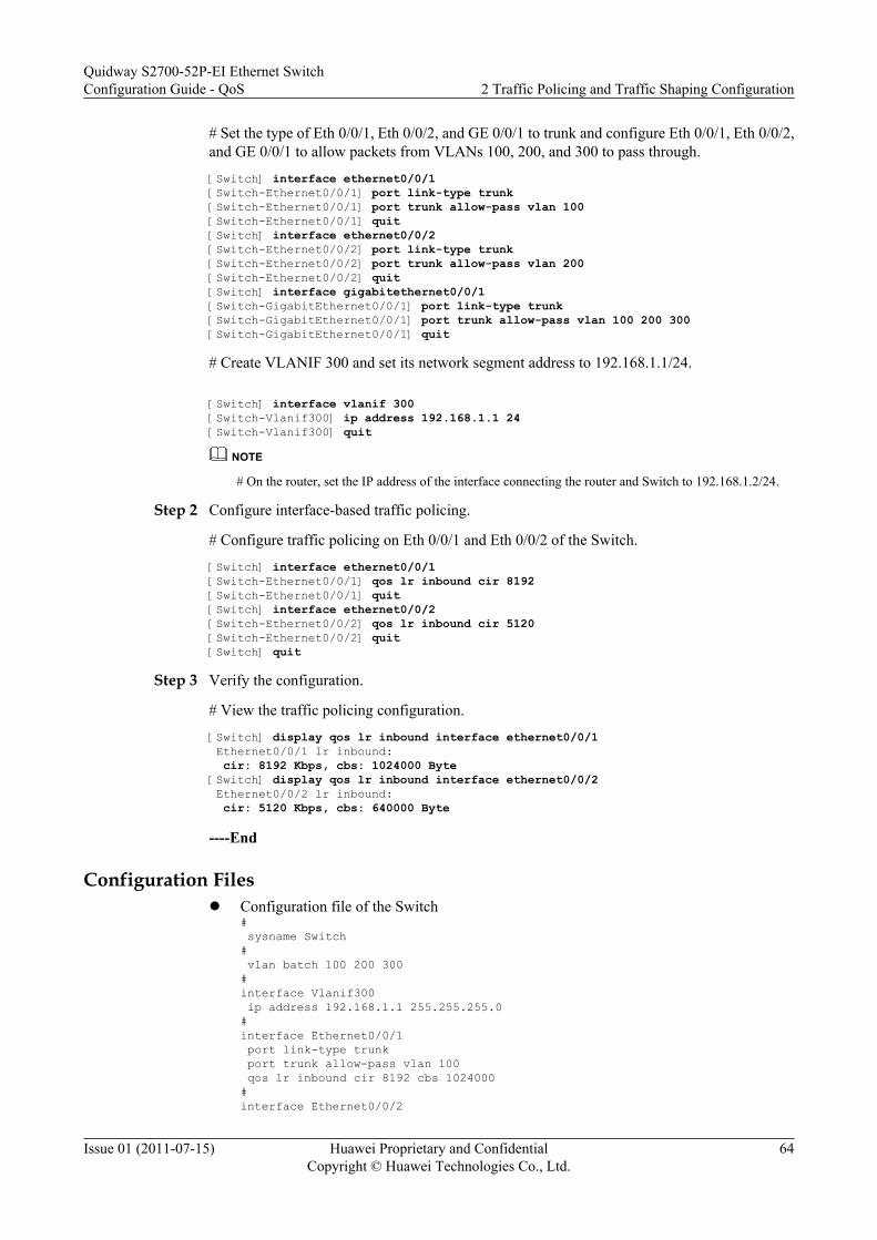
# Set the type of Eth 0/0/1, Eth 0/0/2, and GE 0/0/1 to trunk and configure Eth 0/0/1, Eth 0/0/2,and GE 0/0/1 to allow packets from VLANs 100, 200, and 300 to pass through.
[Switch] interface ethernet0/0/1[Switch-Ethernet0/0/1] port link-type trunk[Switch-Ethernet0/0/1] port trunk allow-pass vlan 100[Switch-Ethernet0/0/1] quit[Switch] interface ethernet0/0/2[Switch-Ethernet0/0/2] port link-type trunk[Switch-Ethernet0/0/2] port trunk allow-pass vlan 200[Switch-Ethernet0/0/2] quit[Switch] interface gigabitethernet0/0/1[Switch-GigabitEthernet0/0/1] port link-type trunk[Switch-GigabitEthernet0/0/1] port trunk allow-pass vlan 100 200 300[Switch-GigabitEthernet0/0/1] quit
# Create VLANIF 300 and set its network segment address to 192.168.1.1/24.
[Switch] interface vlanif 300[Switch-Vlanif300] ip address 192.168.1.1 24[Switch-Vlanif300] quit
NOTE
# On the router, set the IP address of the interface connecting the router and Switch to 192.168.1.2/24.
Step 2 Configure interface-based traffic policing.
# Configure traffic policing on Eth 0/0/1 and Eth 0/0/2 of the Switch.
[Switch] interface ethernet0/0/1[Switch-Ethernet0/0/1] qos lr inbound cir 8192[Switch-Ethernet0/0/1] quit[Switch] interface ethernet0/0/2[Switch-Ethernet0/0/2] qos lr inbound cir 5120[Switch-Ethernet0/0/2] quit[Switch] quit
Step 3 Verify the configuration.
# View the traffic policing configuration.
[Switch] display qos lr inbound interface ethernet0/0/1 Ethernet0/0/1 lr inbound: cir: 8192 Kbps, cbs: 1024000 Byte [Switch] display qos lr inbound interface ethernet0/0/2 Ethernet0/0/2 lr inbound: cir: 5120 Kbps, cbs: 640000 Byte
----End
Configuration Filesl Configuration file of the Switch
# sysname Switch# vlan batch 100 200 300#interface Vlanif300 ip address 192.168.1.1 255.255.255.0#interface Ethernet0/0/1 port link-type trunk port trunk allow-pass vlan 100 qos lr inbound cir 8192 cbs 1024000#interface Ethernet0/0/2
Quidway S2700-52P-EI Ethernet SwitchConfiguration Guide - QoS 2 Traffic Policing and Traffic Shaping Configuration
Issue 01 (2011-07-15) Huawei Proprietary and ConfidentialCopyright © Huawei Technologies Co., Ltd.
64

port link-type trunk port trunk allow-pass vlan 200 qos lr inbound cir 5120 cbs 640000#interface GigabitEthernet0/0/1 port link-type trunk port trunk allow-pass vlan 100 200 300#
return
2.6.2 Example for Configuring Traffic Policing Based on a TrafficClassifier
The Switch provides different bandwidth by configuring traffic policing based on a trafficclassifier and setting different CAR parameters.
Networking RequirementsThe Switch is connected to the router by using GE 0/0/2; enterprise users can access the networkby using the Switch and the router. See Table 2-1.
l Voice services of the enterprise belong to VLAN 120.l Video services of the enterprise belong to VLAN 110.l Data services of the enterprise belong to VLAN 100.
On the Switch, traffic policing needs to be performed on packets of different services to limittraffic within a proper range and ensure bandwidth of each service.
DSCP priorities carried in service packets sent from the user side cannot be trusted and servicesrequire different QoS in practice. Therefore, you need to re-mark DSCP priorities of differentservice packets on the Switch so that the downstream router can process packets based onpriorities.
The requirements are as follows:
Table 2-1 QoS provided by the Switch for upstream traffic
Traffic Type CIR (Mbit/s) PIR (Mbit/s) DSCP Priority
Voice 2 10 46
Video 4 10 30
Data 4 10 14
Quidway S2700-52P-EI Ethernet SwitchConfiguration Guide - QoS 2 Traffic Policing and Traffic Shaping Configuration
Issue 01 (2011-07-15) Huawei Proprietary and ConfidentialCopyright © Huawei Technologies Co., Ltd.
65

Figure 2-4 Network diagram for configuring traffic policing based on a traffic classifier
Enterprise
VLAN 110
VLAN 120
Core network
GE0/0/1 GE0/0/2
Phone
TV
VLAN 100
PC LSW Switch Router
Configuration RoadmapThe configuration roadmap is as follows:
1. Create VLANs and configure interfaces so that enterprise can access the network by usingthe Switch.
2. Create traffic classifiers based on the VLAN ID on the Switch.3. Create traffic behaviors on the Switch to limit the traffic received from the enterprise and
re-mark DSCP priorities of packets.4. Create a traffic policy on the Switch, bind traffic behaviors to traffic classifiers in the traffic
policy, and apply the traffic policy to the interface between the enterprise and the Switch.
Data PreparationTo complete the configuration, you need the following data:l Names of traffic classifiers matching service flowsl Re-marked priorities of packets with different VLAN IDsl Parameters for packets with different VLAN IDs: CIR and PIR valuesl Type and number of the interface to which a traffic policy needs to be applied
Procedure
Step 1 Create VLANs and configure interfaces.
# Create VLAN 100, VLAN 110, and VLAN 120 on the Switch.
<Quidway> system-view[Quidway] sysname Switch[Switch] vlan batch 100 110 120
# Configure the access types of GE 0/0/1 and GE0/0/2 to trunk, add GE 0/0/1 and GE0/0/2 toVLAN 100, VLAN 110, and VLAN 120.
[Switch] interface gigabitethernet 0/0/1[Switch-GigabitEthernet0/0/1] port link-type trunk[Switch-GigabitEthernet0/0/1] port trunk allow-pass vlan 100 110 120
Quidway S2700-52P-EI Ethernet SwitchConfiguration Guide - QoS 2 Traffic Policing and Traffic Shaping Configuration
Issue 01 (2011-07-15) Huawei Proprietary and ConfidentialCopyright © Huawei Technologies Co., Ltd.
66
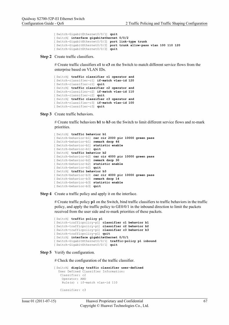
[Switch-GigabitEthernet0/0/1] quit[Switch] interface gigabitethernet 0/0/2[Switch-GigabitEthernet0/0/2] port link-type trunk[Switch-GigabitEthernet0/0/2] port trunk allow-pass vlan 100 110 120[Switch-GigabitEthernet0/0/2] quit
Step 2 Create traffic classifiers.
# Create traffic classifiers c1 to c3 on the Switch to match different service flows from theenterprise based on VLAN IDs.
[Switch] traffic classifier c1 operator and[Switch-classifier-c1] if-match vlan-id 120[Switch-classifier-c1] quit[Switch] traffic classifier c2 operator and[Switch-classifier-c2] if-match vlan-id 110[Switch-classifier-c2] quit[Switch] traffic classifier c3 operator and[Switch-classifier-c3] if-match vlan-id 100[Switch-classifier-c3] quit
Step 3 Create traffic behaviors.
# Create traffic behaviors b1 to b3 on the Switch to limit different service flows and re-markpriorities.
[Switch] traffic behavior b1[Switch-behavior-b1] car cir 2000 pir 10000 green pass[Switch-behavior-b1] remark dscp 46[Switch-behavior-b1] statistic enable[Switch-behavior-b1] quit[Switch] traffic behavior b2[Switch-behavior-b2] car cir 4000 pir 10000 green pass[Switch-behavior-b2] remark dscp 30[Switch-behavior-b2] statistic enable[Switch-behavior-b2] quit[Switch] traffic behavior b3[Switch-behavior-b3] car cir 4000 pir 10000 green pass[Switch-behavior-b3] remark dscp 14[Switch-behavior-b3] statistic enable[Switch-behavior-b3] quit
Step 4 Create a traffic policy and apply it on the interface.
# Create traffic policy p1 on the Switch, bind traffic classifiers to traffic behaviors in the trafficpolicy, and apply the traffic policy to GE0/0/1 in the inbound direction to limit the packetsreceived from the user side and re-mark priorities of these packets.
[Switch] traffic policy p1[Switch-trafficpolicy-p1] classifier c1 behavior b1[Switch-trafficpolicy-p1] classifier c2 behavior b2[Switch-trafficpolicy-p1] classifier c3 behavior b3[Switch-trafficpolicy-p1] quit[Switch] interface gigabitethernet 0/0/1[Switch-GigabitEthernet0/0/1] traffic-policy p1 inbound[Switch-GigabitEthernet0/0/1] quit
Step 5 Verify the configuration.
# Check the configuration of the traffic classifier.
[Switch] display traffic classifier user-defined User Defined Classifier Information: Classifier: c2 Operator: AND Rule(s) : if-match vlan-id 110
Classifier: c3
Quidway S2700-52P-EI Ethernet SwitchConfiguration Guide - QoS 2 Traffic Policing and Traffic Shaping Configuration
Issue 01 (2011-07-15) Huawei Proprietary and ConfidentialCopyright © Huawei Technologies Co., Ltd.
67

Operator: AND Rule(s) : if-match vlan-id 100
Classifier: c1 Operator: AND Rule(s) : if-match vlan-id 120
Total classifier number is 3
# Check the configuration of the traffic policy. Here, the configuration of the traffic policy p1is displayed.
[Switch] display traffic policy user-defined p1 User Defined Traffic Policy Information: Policy: p1 Classifier: c1 Operator: AND Behavior: b1 Committed Access Rate: CIR 2000 (Kbps), CBS 250000 (Byte) PIR 10000 (Kbps), PBS 1250000 (Byte) Green Action : pass Yellow Action : pass Red Action : discard Marking: Remark DSCP ef statistic: enable Classifier: c2 Operator: AND Behavior: b2 Committed Access Rate: CIR 4000 (Kbps), CBS 500000 (Byte) PIR 10000 (Kbps), PBS 1250000 (Byte) Green Action : pass Yellow Action : pass Red Action : discard Marking: Remark DSCP af33 statistic: enable Classifier: c3 Operator: AND Behavior: b3 Committed Access Rate: CIR 4000 (Kbps), CBS 500000 (Byte) PIR 10000 (Kbps), PBS 1250000 (Byte) Green Action : pass Yellow Action : pass Red Action : discard Marking: Remark DSCP af13 statistic: enable
# Check the configuration of the traffic policy applied on an interface. Here, the configurationof the traffic policy applied to GE0/0/1 is displayed.
[Switch] display traffic policy statistics interface gigabitethernet 0/0/1 inbound
Interface: GigabitEthernet0/0/1 Traffic policy inbound: p1 Rule number: 3 Current status: OK!--------------------------------------------------------------------- Board : 0Item Packets Bytes---------------------------------------------------------------------Matched 10 10000 +--Passed 8 8000 +--Dropped 2 2000 +--Filter 2 2000
Quidway S2700-52P-EI Ethernet SwitchConfiguration Guide - QoS 2 Traffic Policing and Traffic Shaping Configuration
Issue 01 (2011-07-15) Huawei Proprietary and ConfidentialCopyright © Huawei Technologies Co., Ltd.
68

+--URPF 0 0 +--CAR 2 2000
----End
Configuration Filesl Configuration file of the Switch
# sysname Switch# vlan batch 100 110 120#traffic classifier c1 operator and if-match vlan-id 120traffic classifier c2 operator and if-match vlan-id 110traffic classifier c3 operator and if-match vlan-id 100#traffic behavior b1 car cir 2000 pir 10000 cbs 250000 pbs 1250000 green pass yellow pass red discard remark dscp ef statistic enabletraffic behavior b2 car cir 4000 pir 10000 cbs 500000 pbs 1250000 green pass yellow pass red discard remark dscp af33 statistic enabletraffic behavior b3 car cir 4000 pir 10000 cbs 500000 pbs 1250000 green pass yellow pass red discard remark dscp af13 statistic enable#traffic policy p1 classifier c1 behavior b1 classifier c2 behavior b2 classifier c3 behavior b3#interface GigabitEthernet0/0/1 port link-type trunk port trunk allow-pass vlan 100 110 120 traffic-policy p1 inbound#interface GigabitEthernet0/0/2 port link-type trunk port trunk allow-pass vlan 100 110 120#return
2.6.3 Example for Configuring Traffic ShapingYou can configure traffic shaping and set different traffic shaping rates for different types ofpackets to reduce the jitter and ensure bandwidth of various services.
Networking RequirementsThe Switch is connected to GE 0/0/2 and the router; the 802.1p priorities of voice, video, anddata services from the Internet are 6, 5, and 2 respectively, and these services can reach usersthrough the router and Switch, as shown in Figure 2-5. The rate of the traffic from the networkside is greater than the rate of the LSW interface; therefore, a jitter may occur in the outbounddirection of GE 0/0/1. To reduce the jitter and ensure the bandwidth of various services, therequirements are as follows:
Quidway S2700-52P-EI Ethernet SwitchConfiguration Guide - QoS 2 Traffic Policing and Traffic Shaping Configuration
Issue 01 (2011-07-15) Huawei Proprietary and ConfidentialCopyright © Huawei Technologies Co., Ltd.
69

l The CIR on the interface is 20000 kbit/s.l The CIR and PIR for the voice service are 3000 kbit/s and 5000 kbit/s respectively.l The CIR and PIR for the video service are 5000 kbit/s and 8000 kbit/s respectively.l The CIR and PIR for the data service are 2000 kbit/s and 3000 kbit/s respectively.
Figure 2-5 Networking diagram for configuring traffic shaping
GE0/0/1 GE0/0/2
Phone
TV
PC LSW Switch Router
CoreNetwork
802.1p=6
802.1p=2
802.1p=5
Residence
Configuration RoadmapThe configuration roadmap is as follows:
1. Create VLANs and configure each interface so that the residential user can access thenetwork through the Switch.
2. Configure interfaces to trust 802.1p priorities of packets.3. Configure traffic shaping on an interface to limit the bandwidth of the interface.4. Configure traffic shaping in an interface queue to limit the CIRs of voice, video, and data
services.
Data PreparationTo complete the configuration, you need the following data:l 802.1p prioritiesl Rate for traffic shaping on an interfacel Rate for traffic shaping in each interface queue
Procedure
Step 1 Create VLANs and configure interfaces.
# Create VLAN 10.
<Quidway> system-view[Quidway] sysname Switch[Switch] vlan batch 10
Quidway S2700-52P-EI Ethernet SwitchConfiguration Guide - QoS 2 Traffic Policing and Traffic Shaping Configuration
Issue 01 (2011-07-15) Huawei Proprietary and ConfidentialCopyright © Huawei Technologies Co., Ltd.
70

# Set the type of GE 0/0/1 and GE 0/0/2 to trunk, and then add GE 0/0/1 and GE 0/0/2 to VLAN10.
[Switch] interface gigabitethernet0/0/1[Switch-GigabitEthernet0/0/1] port link-type trunk[Switch-GigabitEthernet0/0/1] port trunk allow-pass vlan 10[Switch-GigabitEthernet0/0/1] quit[Switch] interface gigabitethernet0/0/2[Switch-GigabitEthernet0/0/2] port link-type trunk[Switch-GigabitEthernet0/0/2] port trunk allow-pass vlan 10[Switch-GigabitEthernet0/0/2] quit
# Create VLANIF 10 and assign network segment address 10.10.10.1/24 to VLANIF 10.
[Switch] interface vlanif 10[Switch-Vlanif10] ip address 10.10.10.1 255.255.255.0[Switch-Vlanif10] quit
NOTE
Assign IP address 10.10.10.2/24 to the interface connecting the router and Switch.
Step 2 Configure the interface to trust packets.
# Configure the interface to trust 802.1p priorities of packets.
[Switch] interface gigabitethernet 0/0/2[Switch-GigabitEthernet0/0/2] trust 8021p[Switch-GigabitEthernet0/0/2] quit
Step 3 Configure traffic shaping on an interface.
# Configure traffic shaping on an interface of the Switch and set the CIR to 20000 kbit/s.
[Switch] interface gigabitethernet 0/0/1[Switch-GigabitEthernet0/0/1] qos lr outbound cir 20000 cbs 2500000
Step 4 Configure traffic shaping in an interface queue.
# Set the scheduling mode of each queue to WRR. Set the WRR weight of queue 6 to 60, WRRweight of queue 5 to 40, and WRR weight of queue 2 to 20. The other queues retain the defaultweight.
[Switch-GigabitEthernet0/0/1] qos wrr[Switch-GigabitEthernet0/0/1] qos queue 6 wrr weight 60[Switch-GigabitEthernet0/0/1] qos queue 5 wrr weight 40[Switch-GigabitEthernet0/0/1] qos queue 2 wrr weight 20
# Configure traffic shaping in the interface queues on the Switch, and then set the CIR and PIRof the voice service to 3000 kbit/s and 5000kbit/s, the CIR and PIR of the video service to 5000kbit/s and 8000 kbit/s, and the CIR and PIR of the data service to 2000 kbit/s and 3000 kbit/s.
[Switch-GigabitEthernet0/0/1] qos queue 6 shaping cir 3000 pir 5000[Switch-GigabitEthernet0/0/1] qos queue 5 shaping cir 5000 pir 8000[Switch-GigabitEthernet0/0/1] qos queue 2 shaping cir 2000 pir 3000[Switch-GigabitEthernet0/0/1] quit[Switch] quit
Step 5 Verify the configuration.
# If the configuration succeeds, the committed bandwidth for the packets transmitted by GE0/0/1is 20000 kbit/s; the transmission rate of the voice service ranges from 3000 kbit/s to 5000 kbit/s; the transmission rate of the video service ranges from 5000 kbit/s to 8000 kbit/s; thetransmission rate of the data service ranges from 2000 kbit/s to 3000 kbit/s.
----End
Quidway S2700-52P-EI Ethernet SwitchConfiguration Guide - QoS 2 Traffic Policing and Traffic Shaping Configuration
Issue 01 (2011-07-15) Huawei Proprietary and ConfidentialCopyright © Huawei Technologies Co., Ltd.
71

Configuration Filesl Configuration file of the Switch
# sysname Switch# vlan batch 10#interface Vlanif10 ip address 10.10.10.1 255.255.255.0#interface GigabitEthernet0/0/1 port link-type trunk port trunk allow-pass vlan 10 qos lr outbound cir 20000 cbs 2500000 qos wrr qos queue 2 wrr weight 20 qos queue 5 wrr weight 40 qos queue 6 wrr weight 60 qos queue 2 shaping cir 2000 pir 3000 qos queue 5 shaping cir 5000 pir 8000 qos queue 6 shaping cir 3000 pir 5000#interface GigabitEthernet0/0/2 port link-type trunk port trunk allow-pass vlan 10 trust 8021p #return
Quidway S2700-52P-EI Ethernet SwitchConfiguration Guide - QoS 2 Traffic Policing and Traffic Shaping Configuration
Issue 01 (2011-07-15) Huawei Proprietary and ConfidentialCopyright © Huawei Technologies Co., Ltd.
72
3 Congestion Avoidance and CongestionManagement Configuration
About This Chapter
This chapter describes the basic concepts of congestion avoidance and congestion management,and provides configuration methods and configuration examples of congestion avoidance andcongestion management.
3.1 Overview of Congestion Avoidance and Congestion ManagementThis section describes the basic concepts of congestion avoidance and congestion management.
3.2 Configuring Congestion AvoidanceAfter congestion avoidance is configured, the S2700-52P-EI processes packets of differentcolors according to the SRED configuration.
3.3 Configuring Congestion ManagementAfter congestion management is configured, if congestion occurs on a network, the S2700-52P-EI determines the sequence of forwarding packets according to the defined scheduling policy.
3.4 Maintaining Congestion Avoidance and Congestion ManagementThis section describes how to maintain traffic avoidance and congestion management.
3.5 Configuration ExamplesThis section provides several configuration examples of congestion avoidance and congestionmanagement.
Quidway S2700-52P-EI Ethernet SwitchConfiguration Guide - QoS
3 Congestion Avoidance and Congestion ManagementConfiguration
Issue 01 (2011-07-15) Huawei Proprietary and ConfidentialCopyright © Huawei Technologies Co., Ltd.
73

3.1 Overview of Congestion Avoidance and CongestionManagement
This section describes the basic concepts of congestion avoidance and congestion management.
3.1.1 Congestion AvoidanceCongestion avoidance is a flow control mechanism. A system configured with congestionavoidance monitors network resource usage such as queues and memory buffers. Whencongestion occurs or aggravates, the system discards packets.
Congestion avoidance mechanisms include tail drop, Random Early Detection (RED) andSimple Random Early Detection (SRED). The S2700-52P-EI performs congestion avoidancebased on Simple Random Early Detection (SRED).
Tail Drop
The traditional packet drop policy uses tail drop. The tail drop policy processes all the packetsuniformly, regardless of their class of service (CoS). When congestion occurs, packets at theend of a queue are discarded until the congestion problem is solved.
The tail drop policy causes global TCP synchronization. When packets from multiple TCPconnections are discarded in a queue, these TCP connections enter the congestion avoidanceand slow start state simultaneously, which is called global TCP synchronization. This causestraffic reduction and will lead to traffic peak. Such a process repeats, which causes the volumeof network traffic to change from heavy to light and affects the link usage.
RED
The RED mechanism randomly discards packets so that the S2700-52P-EI reduces thetransmission speeds of multiple TCP connections at different periods of time. This preventsglobal TCP synchronization.
RED sets the upper threshold and lower threshold for the length of each queue and processespackets as follows:l When the queue length is shorter than the lower threshold, no packet is discarded.l When the queue length exceeds the upper threshold, all the received packets are discarded.l When the queue length ranges from the lower threshold to the upper threshold, incoming
packets are dropped randomly. The system sets a random number for each incoming packet,and compares it with the packet drop probability of the current queue. If the random numberis larger than the drop probability, the packet is dropped. The longer the queue, the higherthe drop probability.
SRED
The S2700-52P-EI implements the Simple Random Early Detection (SRED) technology basedon the RED technology. In a queue on an outbound interface, the S2700-52P-EI colors thepackets red or yellow according to the priorities of packets; the S2700-52P-EI sets a thresholdfor discarding red packets, a threshold for discarding yellow packets, and the drop probability.
Quidway S2700-52P-EI Ethernet SwitchConfiguration Guide - QoS
3 Congestion Avoidance and Congestion ManagementConfiguration
Issue 01 (2011-07-15) Huawei Proprietary and ConfidentialCopyright © Huawei Technologies Co., Ltd.
74

Based on SRED, the S2700-52P-EI actively discards packets in the queue based on the dropprobability to adjust the rate of outgoing traffic at the interface.
3.1.2 Congestion ManagementWhen intermittent congestion occurs on the network, delay-sensitive services require higherQoS than others. In this case, congestion management is required. The bandwidth needs to beincreased if a network is always congested.
Congestion management uses the queue scheduling technologies. Currently, the S2700-52P-EI adopts the following queue scheduling modes:
l PQ Scheduling
l WRR Scheduling
l DRR Scheduling
l PQ+WRR/PQ+DRR Scheduling
PQ Scheduling
Priority Queuing (PQ) scheduling is a queuing technology by which packets are scheduled basedon the priorities of queues in a strict manner. The packets of lower priorities can be scheduledonly after packets of higher priorities are scheduled.
In PQ scheduling mode, packets of delay-sensitive core services are put into a high priority queueand packets of other non-core services are put into a low priority queue. This ensures that coreservices are sent first.
The disadvantage of PQ scheduling is that the packets of lower priorities are not processed ifthere are a large number of packets of higher priorities, when congestion occurs.
WRR Scheduling
WRR refers to Weighted Round Robin. WRR schedules packets of queues in a polling manner,ensuring that packets in each queue are sent at a certain time.
Assume that there are eight output queues on an interface. WRR sets weights for the eight queues,that is, w7, w6, w5, w4, w3, w2, w1, and w0. The weight indicates a percentage of obtainingresources. For example, the weights of queues on a 100-Mbit/s interface are set to 50, 50, 30,30, 10, 10, 10, and 10, corresponding to w7, w6, w5, w4, w3, w2, w1, and w0. In this case, thelowest priority queue can obtain bandwidth of at least 5 Mbit/s. This avoids the disadvantage ofPQ scheduling.
The advantage of WRR is as follows: Although packets in multiple queues are processed in apolling manner, the time allocated to each queue is not fixed. If a queue is null, packets of thenext queue are scheduled. This ensures better usage of bandwidth.
The disadvantages of WRR are as follows:
l WRR allocates bandwidth according to the number of packets. When the average lengthof packets in each queue is the same or known, you can obtain the required bandwidth bysetting the weight of WRR. You, however, cannot obtain the required bandwidth by settingthe weight of WRR when the average length of packets in each queue changes.
l The packets of short-delay services such as voice services cannot be scheduled in time.
Quidway S2700-52P-EI Ethernet SwitchConfiguration Guide - QoS
3 Congestion Avoidance and Congestion ManagementConfiguration
Issue 01 (2011-07-15) Huawei Proprietary and ConfidentialCopyright © Huawei Technologies Co., Ltd.
75

DRR Scheduling
The principle of Deficit Round Robin (DRR) is similar to the principle of WRR.
Their difference is that WRR schedules packets according to the number of packets, but DRRschedules packets according to the length of packets. If the packet length exceeds the schedulingcapability of a queue, DRR allows the deficit weight to ensure that packets of a long length arescheduled. When packets are scheduled in a polling manner again, this queue is not scheduleduntil the weight becomes positive. Then, this queue participates in DRR scheduling.
DRR scheduling offsets the disadvantage of PQ scheduling and one disadvantage of WRRscheduling (that is, bandwidth cannot be obtained according to the proportion).
The packets of short-delay services such as voice services cannot be scheduled in time in DRRmode.
PQ+WRR/PQ+DRR Scheduling
PQ scheduling, WRR scheduling, and DRR scheduling have their own advantages anddisadvantages. If only PQ scheduling is used, packets of lower priorities cannot obtain thebandwidth for a long time. If only WRR or DRR scheduling is used, delay-sensitive servicessuch as voice service cannot be scheduled first. PQ+WRR or PQ+DRR scheduling can use theadvantages of both PQ and WRR or DRR scheduling and offset their disadvantages.
Through PQ+WRR or PQ+DRR scheduling, important protocol packets and delay-sensitiveservice packets are put in a PQ queue and specified bandwidth is allocated to this queue; otherpackets are put into a WRR or DRR queue according to their priorities and scheduled in a pollingmanner according to the weight of the queue.
3.2 Configuring Congestion AvoidanceAfter congestion avoidance is configured, the S2700-52P-EI processes packets of differentcolors according to the SRED configuration.
3.2.1 Establishing the Configuration TaskBefore configuring congestion avoidance, familiarize yourself with the applicable environment,complete the pre-configuration tasks, and obtain the required data. This will help you completethe configuration task quickly and accurately.
Applicable Environment
To prevent congestion and solve the problem of global TCP synchronization, you can configureRED to adjust the traffic on a network and remove the overload of the traffic on a network.
Pre-configuration Tasks
Before configuring congestion avoidance, complete the following tasks on the incominginterface:
l Configuring priority mapping based on simple traffic classification to map priorities ofpackets to PHBs and colors
Quidway S2700-52P-EI Ethernet SwitchConfiguration Guide - QoS
3 Congestion Avoidance and Congestion ManagementConfiguration
Issue 01 (2011-07-15) Huawei Proprietary and ConfidentialCopyright © Huawei Technologies Co., Ltd.
76

l Configuring traffic policing based on complex traffic classification and the remarkingaction
NOTE
Before configuring congestion avoidance, you need to perform either of the preceding tasks to color packetsas the basis of congestion avoidance.
Data Preparation
To configure congestion avoidance, you need the following data.
No. Data
1 Upper threshold, lower threshold, and maximum drop percent of RED
3.2.2 (Optional) Setting the Length of the Interface QueueYou can set the maximum number of packets that can be buffered in the specified interface queueby setting the length of the interface queue.
Context
You must run the shutdown (interface view) command to shut down the interface before runningthe qos queue max-length command. Otherwise, traffic is interrupted and an alarm is generated.
Procedure
Step 1 Run:system-view
The system view is displayed.
Step 2 Run:interface interface-type interface-number
The interface view is displayed.
Step 3 Run:qos queue queue-index max-length packet-number
The length of the interface priority queue is set.
----End
3.2.3 (Optional) Setting the Minimum Size of the Static Buffer inan Interface Queue
You can set the minimum size of the static buffer in an interface queue to ensure that there isavailable buffer space in the queue. Otherwise, traffic may be lost because of the queue cannotobtain the buffer.
Quidway S2700-52P-EI Ethernet SwitchConfiguration Guide - QoS
3 Congestion Avoidance and Congestion ManagementConfiguration
Issue 01 (2011-07-15) Huawei Proprietary and ConfidentialCopyright © Huawei Technologies Co., Ltd.
77

Procedure
Step 1 Run:system-view
The system view is displayed.
Step 2 Run:interface interface-type interface-number
The interface view is displayed.
Step 3 Run:qos queue queue-index static-cell cell-number
The minimum size of the static buffer in an interface queue is set.
----End
3.2.4 (Optional) Configuring the CFI Field as the Internal DropPriority
After the CFI field is configured as the internal drop priority, if the rate of packets exceeds theCIR, the S2700-52P-EI sets the value of the CFI field in packets to 1. When congestion occurs,the S2700-52P-EI first discards the packets with the CFI field being 1.
ContextThe Canonical Format Indicator (CFI) field in a VLAN tag is also called the Drop EligibleIndicator (DEI), and is used to mark the drop priority of packets in certain situations. When therate of packets exceeds the CIR, the S2700-52P-EI sets the DEI field of the packets to 1. Thatis, these packets have a high drop priority. If congestion occurs, subsequent devices first discardpackets with the DEI field being 1.
If you need to set the CFI field as the internal drop priority on multiple interfaces, you canperform the configuration on the port group.
Procedure
Step 1 Run:system-view
The system view is displayed.
Step 2 Run:interface interface-type interface-number
The interface view is displayed.
Or run the port-group port-group-name command to enter the port group view.
NOTE
l The interface type can be Ethernet, GE, or Eth-Trunk.
l You need to create a port group before performing this task. For details about creating a port group,see Configuring the Interface Group in the Quidway S2700-52P-EI Ethernet Switches ConfigurationGuide - Ethernet.
Quidway S2700-52P-EI Ethernet SwitchConfiguration Guide - QoS
3 Congestion Avoidance and Congestion ManagementConfiguration
Issue 01 (2011-07-15) Huawei Proprietary and ConfidentialCopyright © Huawei Technologies Co., Ltd.
78

Step 3 Run:dei enable
The CFI field is configured as the internal drop priority.
By default, the CFI field is not configured as the internal drop priority.
----End
3.2.5 Setting SRED ParametersYou can set SERD parameters, that is, the drop threshold and drop probability for packets ofdifferent colors, to implement congestion avoidance.
ContextNOTEWhen SRED-based congestion avoidance is configured:
The drop threshold and drop probability set for queues 0 to 4 take effect for red packets, but do not takeeffect for yellow packets. The drop threshold and drop probability set for queues 5 to 7 take effect foryellow packets, but do not take effect for red packets.
Do as follows on the S2700-52P-EI on which SRED parameters need to be set.
Procedure
Step 1 Run:system-view
The system view is displayed.
Step 2 Run:qos sred queue queue-index red start-discard-point discard-probability discard-probability yellow start-discard-point discard-probability discard-probability
The drop threshold and drop probability of queues are set.
Each queue has its own SRED parameters to prevent congestion. Therefore, repeat this step foreach queue.
----End
3.2.6 Checking the ConfigurationAfter congestion avoidance is configured, you can view the drop threshold and drop probabilityfor red and yellow packets in queues.
PrerequisiteThe configurations of SRED parameters are complete.
Procedurel Run the display qos sred command to check the drop threshold and drop probability for
red and yellow packets in queues.
Quidway S2700-52P-EI Ethernet SwitchConfiguration Guide - QoS
3 Congestion Avoidance and Congestion ManagementConfiguration
Issue 01 (2011-07-15) Huawei Proprietary and ConfidentialCopyright © Huawei Technologies Co., Ltd.
79
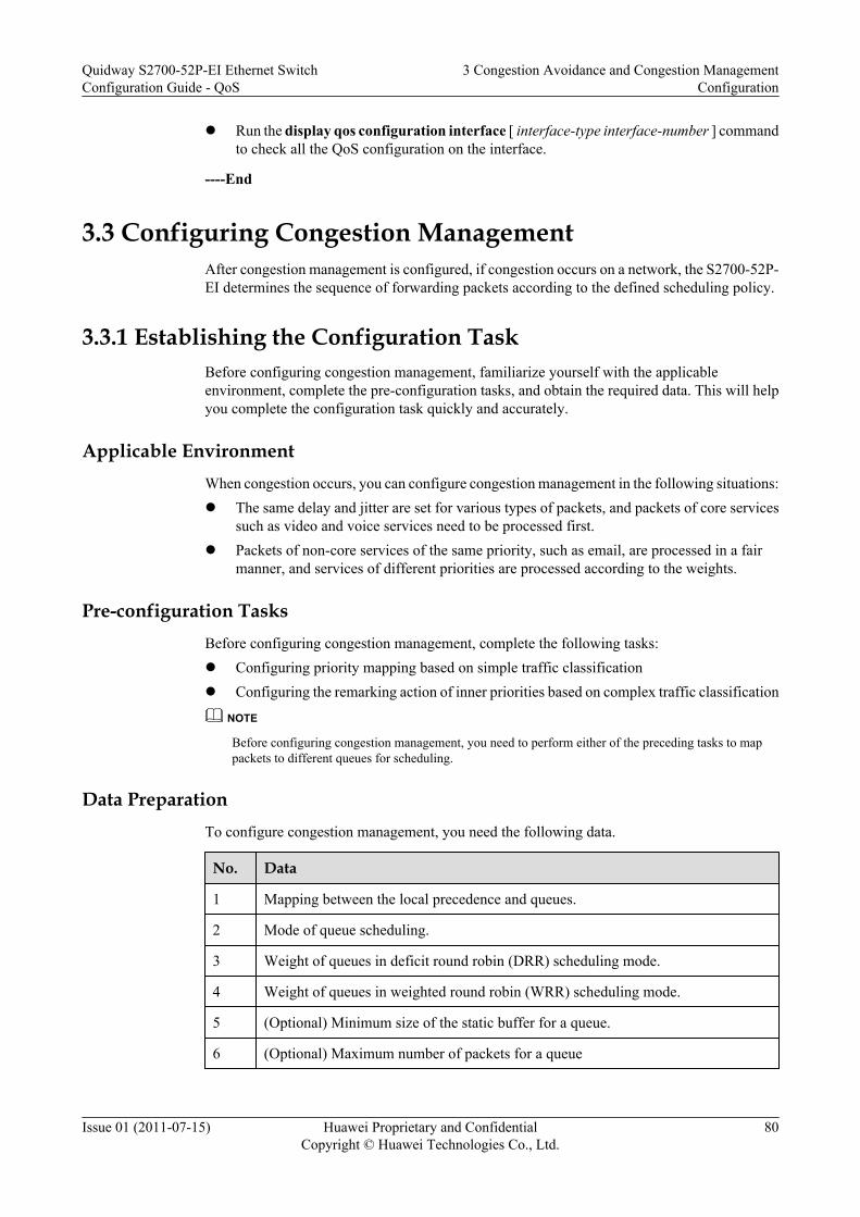
l Run the display qos configuration interface [ interface-type interface-number ] commandto check all the QoS configuration on the interface.
----End
3.3 Configuring Congestion ManagementAfter congestion management is configured, if congestion occurs on a network, the S2700-52P-EI determines the sequence of forwarding packets according to the defined scheduling policy.
3.3.1 Establishing the Configuration TaskBefore configuring congestion management, familiarize yourself with the applicableenvironment, complete the pre-configuration tasks, and obtain the required data. This will helpyou complete the configuration task quickly and accurately.
Applicable EnvironmentWhen congestion occurs, you can configure congestion management in the following situations:l The same delay and jitter are set for various types of packets, and packets of core services
such as video and voice services need to be processed first.l Packets of non-core services of the same priority, such as email, are processed in a fair
manner, and services of different priorities are processed according to the weights.
Pre-configuration TasksBefore configuring congestion management, complete the following tasks:l Configuring priority mapping based on simple traffic classificationl Configuring the remarking action of inner priorities based on complex traffic classification
NOTE
Before configuring congestion management, you need to perform either of the preceding tasks to mappackets to different queues for scheduling.
Data PreparationTo configure congestion management, you need the following data.
No. Data
1 Mapping between the local precedence and queues.
2 Mode of queue scheduling.
3 Weight of queues in deficit round robin (DRR) scheduling mode.
4 Weight of queues in weighted round robin (WRR) scheduling mode.
5 (Optional) Minimum size of the static buffer for a queue.
6 (Optional) Maximum number of packets for a queue
Quidway S2700-52P-EI Ethernet SwitchConfiguration Guide - QoS
3 Congestion Avoidance and Congestion ManagementConfiguration
Issue 01 (2011-07-15) Huawei Proprietary and ConfidentialCopyright © Huawei Technologies Co., Ltd.
80

3.3.2 (Optional) Setting the Length of the Interface QueueYou can set the maximum number of packets that can be buffered in the specified interface queueby setting the length of the interface queue.
Context
You must run the shutdown (interface view) command to shut down the interface before runningthe qos queue max-length command. Otherwise, traffic is interrupted and an alarm is generated.
Procedurel 1. Run:
system-view
The system view is displayed.
2. Run:interface interface-type interface-number
The interface view is displayed.
3. Run:qos queue queue-index max-length packet-number
The length of the interface priority queue is set.
----End
3.3.3 (Optional) Setting the Minimum Size of the Static Buffer inan Interface Queue
You can set the minimum size of the static buffer in an interface queue to ensure that there isavailable buffer space in the queue. Otherwise, traffic may be lost because of the queue cannotobtain the buffer.
Procedure
Step 1 Run:system-view
The system view is displayed.
Step 2 Run:interface interface-type interface-number
The interface view is displayed.
Step 3 Run:qos queue queue-index static-cell cell-number
The minimum size of the static buffer in an interface queue is set.
----End
Quidway S2700-52P-EI Ethernet SwitchConfiguration Guide - QoS
3 Congestion Avoidance and Congestion ManagementConfiguration
Issue 01 (2011-07-15) Huawei Proprietary and ConfidentialCopyright © Huawei Technologies Co., Ltd.
81

3.3.4 Setting the Scheduling Mode for an Interface QueueThe S2700-52P-EI supports the following scheduling modes: PQ, DRR, WRR, PQ+DRR, andPQ+WRR.
ContextThe S2700-52P-EI supports eight interface queues that can use different scheduling algorithms.During queue scheduling, packets in a PQ queue are first scheduled. If there are multiple PQqueues, the packets are scheduled in descending order of priorities of these PQ queues. Afterpackets in PQ queues are scheduled, packets in WRR or DRR queues are scheduled in a pollingmanner.
If you need to set the same scheduling parameters on multiple interfaces, you can perform theconfiguration on the port group to reduce the workload.
ProcedureStep 1 Run:
system-view
The system view is displayed.
Step 2 Run:interface interface-type interface-number
The interface view is displayed.
Or run the port-group port-group-name command to enter the port group view.
NOTE
You need to create a port group before performing this task. For details about creating a port group, see(Optional) Configuring the Interface Group in the Quidway S2700-52P-EI Ethernet Switches ConfigurationGuide - Ethernet.
Step 3 Run:qos { pq | wrr | drr }
The scheduling mode of an interface queue is set to PQ, WRR, or DRR.
By default, WRR scheduling is used.
Step 4 (Optional) Run:qos queue queue-index wrr weight weight
The weight of an interface queue in WRR mode is set.
By default, the weight in WRR mode is 1.
You need to perform this step only when the scheduling mode of an interface queue is set toWRR or PQ+WRR.
NOTE
When WRR scheduling is applied and the weight of a queue is set to 0, the queue applies PQ schedulingand other queues apply WRR scheduling. That is, the overall scheduling mode is PQ+WRR.
Step 5 (Optional) Run:
qos queue queue-index drr weight weight
Quidway S2700-52P-EI Ethernet SwitchConfiguration Guide - QoS
3 Congestion Avoidance and Congestion ManagementConfiguration
Issue 01 (2011-07-15) Huawei Proprietary and ConfidentialCopyright © Huawei Technologies Co., Ltd.
82

The weight of an interface queue in DRR mode is set.
By default, the weight in DRR mode is 1.
You need to perform this step only when the scheduling mode of an interface queue is set toDRR or PQ+DRR.
NOTE
When DRR scheduling is applied and the weight of a queue is set to 0, the queue applies PQ schedulingand other queues apply DRR scheduling. That is, the overall scheduling mode is PQ+DRR.
----End
3.3.5 Checking the ConfigurationAfter congestion management is configured, you can view the queue-based traffic statistics andthe scheduling parameters of the queues on a specified interface.
PrerequisiteThe congestion management configurations are complete.
Procedurel Run the display qos local-precedence-queue-map command to check the mappings
between local precedences and queues.
l Run the display qos static-cell [ interface interface-type interface-number { queue queue-index | all } ] command to check the static buffer size of the interface queue.
l Run the display qos max-length [ interface interface-type interface-number { queuequeue-index | all} ] command to check the maximum number of packets that can be bufferedin an interface queue.
l Run the display qos configuration interface [ interface-type interface-number ] commandto check all the QoS configurations on the interface.
----End
3.4 Maintaining Congestion Avoidance and CongestionManagement
This section describes how to maintain traffic avoidance and congestion management.
3.4.1 Displaying the Queue-based StatisticsYou can use display commands to view the queue-based traffic statistics such as the number offorwarded and discarded packets.
ContextTo view the queue-based traffic statistics, run the following command in any view.
Quidway S2700-52P-EI Ethernet SwitchConfiguration Guide - QoS
3 Congestion Avoidance and Congestion ManagementConfiguration
Issue 01 (2011-07-15) Huawei Proprietary and ConfidentialCopyright © Huawei Technologies Co., Ltd.
83

Procedurel Run the following commands to view the queue-based traffic statistics based on device
model.
– Run the display qos queue statistics [ queue queue-index { inbound interfaceinterface-type interface-number | outbound interface interface-type interface-number [ form interface { interface-type interface-number | all } ] } ] command toview the queue-based traffic statistics.
NOTE
Before viewing the queue-based traffic statistics on an interface, run the qos queue statisticsenable command to enable the queue-based traffic statistics function on the specified outboundinterface.
l Run the display qos port statistics interface interface-type interface-number commandto view the queue-based statistics.
NOTE
Before viewing the queue statistics on an interface, run the qos port statistics enable command toenable the queue statistics function on the specified outbound interface.
l Run the display qos hol-drop [ interface interface-type interface-number [ queue queue-index ] ] command to view the statistics about dropped packets caused by congestion oninterfaces and in queues.
NOTE
After the qos port statistics enable or qos queue statistics enable command is run, the statisticsthat the display qos hol-drop command displays are inaccurate. To use the display qos hol-dropcommand to view the statistics again, run the undo qos port statistics enable or undo qos queuestatistics enable command, and then run the display qos hol-drop command to clear the statisticson interfaces and in queues.
----End
3.4.2 Clearing the Queue-based StatisticsYou can use the reset command to clear the queue-based traffic statistics.
Context
To re-collect the queue-based statistics on an interface, you can use the following command inthe user view to clear the previous statistics.
CAUTIONThe queue-based statistics cannot be restored after you clear them. So, confirm the action beforeyou use the command.
Procedurel Clear the queue-based traffic statistics on the S2700-52P-EI.
– Run the reset qos queue statistics [ queue queue-index { inbound interface interface-type interface-number | outbound interface interface-type interface-number [ form
Quidway S2700-52P-EI Ethernet SwitchConfiguration Guide - QoS
3 Congestion Avoidance and Congestion ManagementConfiguration
Issue 01 (2011-07-15) Huawei Proprietary and ConfidentialCopyright © Huawei Technologies Co., Ltd.
84
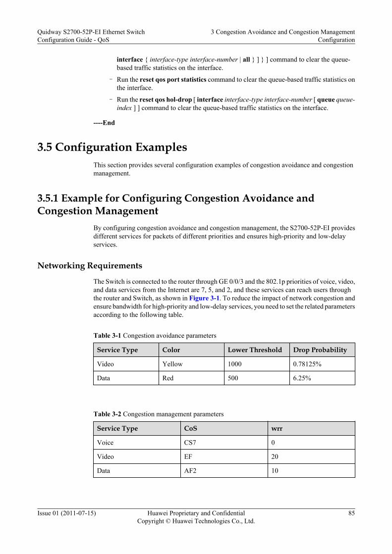
interface { interface-type interface-number | all } ] } ] command to clear the queue-based traffic statistics on the interface.
– Run the reset qos port statistics command to clear the queue-based traffic statistics onthe interface.
– Run the reset qos hol-drop [ interface interface-type interface-number [ queue queue-index ] ] command to clear the queue-based traffic statistics on the interface.
----End
3.5 Configuration ExamplesThis section provides several configuration examples of congestion avoidance and congestionmanagement.
3.5.1 Example for Configuring Congestion Avoidance andCongestion Management
By configuring congestion avoidance and congestion management, the S2700-52P-EI providesdifferent services for packets of different priorities and ensures high-priority and low-delayservices.
Networking Requirements
The Switch is connected to the router through GE 0/0/3 and the 802.1p priorities of voice, video,and data services from the Internet are 7, 5, and 2, and these services can reach users throughthe router and Switch, as shown in Figure 3-1. To reduce the impact of network congestion andensure bandwidth for high-priority and low-delay services, you need to set the related parametersaccording to the following table.
Table 3-1 Congestion avoidance parameters
Service Type Color Lower Threshold Drop Probability
Video Yellow 1000 0.78125%
Data Red 500 6.25%
Table 3-2 Congestion management parameters
Service Type CoS wrr
Voice CS7 0
Video EF 20
Data AF2 10
Quidway S2700-52P-EI Ethernet SwitchConfiguration Guide - QoS
3 Congestion Avoidance and Congestion ManagementConfiguration
Issue 01 (2011-07-15) Huawei Proprietary and ConfidentialCopyright © Huawei Technologies Co., Ltd.
85

Figure 3-1 Networking diagram for configuring congestion avoidance and congestionmanagement
Core Network
802.1p=2
GE0/0/1
GE0/0/3
TV
802.1p=5
PCLSW
Switch
Router
802.1p=5
802.1p=2
TV
PhonePC
LSW
GE0/0/2
802.1p=7
Phone
802.1p=7
Residentialuser 1
Residentialuser N
Configuration RoadmapThe configuration roadmap is as follows:
1. Configure the VLAN for each interface so that devices can communicate with each other.2. Configure interfaces to trust 802.1p priorities of packets.3. Set scheduling parameters of queues.4. Set the drop threshold and drop probability of queues.
Data PreparationTo complete the configuration, you need the following data:l VLAN IDs of data packets, video packets, and voice packets: VLANs 10, 20, and 30l 802.1p priorities of data packets, video packets, and voice packets: 2, 5, and 7l Drop threshold and drop probability of queuesl Schedule parameters of each queue
Procedure
Step 1 Configure the VLAN for each interface so that devices can communicate with each other.<Quidway> system-view[Quidway] sysname Switch[Switch] vlan batch 10 20 30
Quidway S2700-52P-EI Ethernet SwitchConfiguration Guide - QoS
3 Congestion Avoidance and Congestion ManagementConfiguration
Issue 01 (2011-07-15) Huawei Proprietary and ConfidentialCopyright © Huawei Technologies Co., Ltd.
86

[Switch] interface gigabitethernet0/0/1[Switch-GigabitEthernet0/0/1] port link-type trunk[Switch-GigabitEthernet0/0/1] port trunk allow-pass vlan 10 20 30[Switch-GigabitEthernet0/0/1] quit[Switch] interface gigabitethernet0/0/2[Switch-GigabitEthernet0/0/2] port link-type trunk[Switch-GigabitEthernet0/0/2] port trunk allow-pass vlan 10 20 30[Switch-GigabitEthernet0/0/2] quit[Switch] interface gigabitethernet0/0/3[Switch-GigabitEthernet0/0/3] port link-type trunk[Switch-GigabitEthernet0/0/3] port trunk allow-pass vlan 10 20 30[Switch-GigabitEthernet0/0/3] quit
Step 2 Configure interfaces to trust 802.1p priorities of packets.[Switch] interface gigabitethernet 0/0/3[Switch-GigabitEthernet0/0/3] trust 8021p[Switch-GigabitEthernet0/0/3] quit
Step 3 Configure congestion avoidance.
# Set the drop threshold and drop probability of queues.
[Switch] qos sred queue 2 red 500 discard-probability 1 yellow 1000 discard-probability 4[Switch] qos sred queue 5 red 500 discard-probability 1 yellow 1000 discard-probability 4[Switch] qos sred queue 7 red 500 discard-probability 1 yellow 1000 discard-probability 4
Step 4 Configure congestion management.
# Set the scheduling mode of each queue on GE 0/0/1 and GE 0/0/2 on the Switch.
[Switch] interface gigabitethernet 0/0/1[Switch-GigabitEthernet0/0/1] qos wrr[Switch-GigabitEthernet0/0/1] qos queue 7 wrr weight 0[Switch-GigabitEthernet0/0/1] qos queue 5 wrr weight 20[Switch-GigabitEthernet0/0/1] qos queue 2 wrr weight 10[Switch-GigabitEthernet0/0/1] quit[Switch] interface gigabitethernet 0/0/2[Switch-GigabitEthernet0/0/2] qos wrr[Switch-GigabitEthernet0/0/2] qos queue 7 wrr weight 0[Switch-GigabitEthernet0/0/2] qos queue 5 wrr weight 20[Switch-GigabitEthernet0/0/2] qos queue 2 wrr weight 10[Switch-GigabitEthernet0/0/2] quit
Step 5 Verify the configuration.
# View the global SRED configuration of the interface queue in the outbound direction.
<Switch> display qos sredCurrent sred configuration:qos sred queue-index 2 red 500 discard-probability 1 yellow 1000 discard-probability 4qos sred queue-index 5 red 500 discard-probability 1 yellow 1000 discard-probability 4qos sred queue-index 7 red 500 discard-probability 1 yellow 1000 discard-probability 4
----End
Configuration Filesl Configuration file of the Switch
# sysname Switch# vlan batch 10 20 30
Quidway S2700-52P-EI Ethernet SwitchConfiguration Guide - QoS
3 Congestion Avoidance and Congestion ManagementConfiguration
Issue 01 (2011-07-15) Huawei Proprietary and ConfidentialCopyright © Huawei Technologies Co., Ltd.
87

# qos sred queue 2 red 500 discard-probability 1 yellow 1000 discard-probability 4 qos sred queue 5 red 500 discard-probability 1 yellow 1000 discard-probability 4 qos sred queue 7 red 500 discard-probability 1 yellow 1000 discard-probability 4
interface GigabitEthernet0/0/1 port link-type trunk port trunk allow-pass vlan 10 20 30 qos queue 2 wrr weight 10 qos queue 5 wrr weight 20 qos queue 7 wrr weight 0 #interface GigabitEthernet0/0/2 port link-type trunk port trunk allow-pass vlan 10 20 30 qos queue 2 wrr weight 10 qos queue 5 wrr weight 20 qos queue 7 wrr weight 0#interface GigabitEthernet0/0/3 port link-type trunk port trunk allow-pass vlan 10 20 30 trust 8021p#return
Quidway S2700-52P-EI Ethernet SwitchConfiguration Guide - QoS
3 Congestion Avoidance and Congestion ManagementConfiguration
Issue 01 (2011-07-15) Huawei Proprietary and ConfidentialCopyright © Huawei Technologies Co., Ltd.
88