Conext™ Configuration Tool · Chapter 1, “Introduction and Installation” introduces Conext...
130
AC1 AC2 Event Equalize kW A Charging ! Inverting Conext™ Configuration Tool Owner’s Guide Version 1.00 www.SEsolar.com
Transcript of Conext™ Configuration Tool · Chapter 1, “Introduction and Installation” introduces Conext...

AC1
AC2
Event
Equalize
kW
ACharging
!
Inverting
Conext™ Configuration Tool
Owner’s Guide
Version 1.00
www.SEsolar.com
Copyright and Contact
Copyright © 2012, 2014 Schneider Electric. All Rights Reserved.
All trademarks are owned by Schneider Electric Industries SAS or its affiliated companies.
Exclusion for DocumentationUNLESS SPECIFICALLY AGREED TO IN WRITING, SELLER
(A) MAKES NO WARRANTY AS TO THE ACCURACY, SUFFICIENCY OR SUITABILITY OF ANY TECHNICAL OR OTHER INFORMATION PROVIDED IN ITS MANUALS OR OTHER DOCUMENTATION;(B) ASSUMES NO RESPONSIBILITY OR LIABILITY FOR LOSSES, DAMAGES, COSTS OR EXPENSES, WHETHER SPECIAL, DIRECT, INDIRECT, CONSEQUENTIAL OR INCIDENTAL, WHICH MIGHT ARISE OUT OF THE USE OF SUCH INFORMATION. THE USE OF ANY SUCH INFORMATION WILL BE ENTIRELY AT THE USER’S RISK; AND
(C) REMINDS YOU THAT IF THIS MANUAL IS IN ANY LANGUAGE OTHER THAN ENGLISH, ALTHOUGH STEPS HAVE BEEN TAKEN TO MAINTAIN THE ACCURACY OF THE TRANSLATION, THE ACCURACY CANNOT BE GUARANTEED. APPROVED CONTENT IS CONTAINED WITH THE ENGLISH LANGUAGE VERSION WHICH IS POSTED AT WWW.SESOLAR.COM.
Document Number: 975-0720-01-01 Revision: Revision A Date: 07-2014
Contact Information
www.SEsolar.com
Please contact your local Schneider Electric Sales Representative or visit our website at:http://www.schneider-electric.com/sites/corporate/en/support/operations/local-operations/local-operations.pageCopyright and Contact
Information About Your SystemAs soon as you open your product, record the following information and be sure to keep your proof of purchase.
Serial Number _________________________________
Product Number _________________________________
Purchased From _________________________________
Purchase Date _________________________________
About This Guide
About This Guide
Purpose
The purpose of this Owner’s Guide is to provide explanations and procedures for installing and operating the Schneider Electric Conext Configuration Tool.
Scope
The Guide provides safety guidelines, detailed planning and setup information, procedures for installing the software, as well as information about operating and troubleshooting the unit. This Guide does not provide details about particular brands of batteries, photoelectric cells, or generators. Consult individual battery manufacturers for this information.
Audience
The Guide is intended for any qualified personnel planning to install and operate Conext Configuration Tool. Certain configuration tasks should only be performed by qualified personnel in consultation with your local utility and/or an authorized dealer. Electrical equipment should be installed, operated, serviced, and maintained only by qualified personnel. Keep unqualified personnel away from batteries. Servicing of batteries must only be performed or supervised by qualified personnel with knowledge of batteries and their required precautions.Qualified personnel have training, knowledge, and experience in:
• Working with distributed power sources
• Installing electrical equipment
• Applying applicable installation codes
• Analyzing and reducing the hazards involved in performing electrical work
• Installing and configuring batteries
• Installing hardware and software on a Windows-based computer
• Selecting and using Personal Protective Equipment (PPE)
No responsibility is assumed by Schneider Electric for any consequences arising out of the use of this material.
Organization
This Guide is organized into five chapters and one appendix:
Chapter 1, “Introduction and Installation” introduces Conext Configuration Tool and describes how to install the software and connect Conext Configuration Tool to the Xanbus network.
Chapter 2 contains information and procedures to configure a Conext XW+ Inverter/Charger system using the Conext Configuration Tool Configuration Wizards.
975-0720-01-01 iiiThis manual is for use by qualified personnel only
About This Guide
Chapter 3, “Device Configuration” describes how to use Conext Configuration Tool to configure each device in the system.
Chapter 4, “System Logging” contains information and procedures to use the Conext Configuration Tool system logging feature.
Chapter 5, “Upgrading Firmware” contains information about upgrading device firmware using Conext Configuration Tool.
Appendix A, “Legacy USB-to-Xanbus Adapters” provides information about installing older versions of the USB-to-Xanbus adapter.
Related Information
You can find more information about Schneider Electric as well as its products and services at www.SEsolar.com
Disclaimer
This Conext Configuration Tool software is provided by Schneider Electric Industries SAS ("Schneider Electric") to you free of charge. Schneider Electric does not warrant that the software will operate uninterrupted, that it is free from defects or errors, or that it is suitable for certain purposes. The software is used at your risk and responsibility. SCHNEIDER ELECTRIC HEREBY DISCLAIMS ALL WARRANTIES, WHETHER STATUTORY, EXPRESS, OR IMPLIED, INCLUDING ALL WARRANTIES OF MERCHANTABILITY AND FITNESS FOR PARTICULAR PURPOSE, AND ALL WARRANTIES ARISING FROM COURSE OF DEALING OR USAGE OF TRADE. IN NO EVENT SHALL SCHNEIDER ELECTRIC BE LIABLE FOR ANY INDIRECT, SPECIAL, INCIDENTAL, OR CONSEQUENTIAL DAMAGES, LOSS, EXPENSE OR CAUSE OF ACTION, WHETHER BASED IN CONTRACT, WARRANTY, TORT (INCLUDING NEGLIGENCE), STRICT LIABILITY, STATUTE, OR OTHERWISE, INCLUDING, WITHOUT LIMITATION, DAMAGES FOR LOSS OF BUSINESS, LOSS OF PROFITS, BUSINESS INTERRUPTION, LOSS OF DATA, OR FOR ANY OTHER PECUNIARY OR NON-PECUNIARY LOSS OR DAMAGE ARISING OUT OF OR IN CONNECTION WITH THE INABILITY TO USE OR THE MISUSE OF THE SOFTWARE, EVEN IF SCHNEIDER ELECTRIC HAS BEEN ADVISED OF THE POSSIBILITY OF SUCH DAMAGES.
iv 975-0720-01-01This manual is for use by qualified personnel only
Safety
Important Safety Instructions
READ AND SAVE THESE INSTRUCTIONS - DO NOT DISCARD
This guide contains important safety instructions for Conext Configuration Tool that must be followed during installation procedures. Read and keep this Installation Guide for future reference.
Read these instructions carefully and look at the equipment to become familiar with the device before trying to install, operate, service or maintain it. The following special messages may appear throughout this bulletin or on the equipment to warn of potential hazards or to call attention to information that clarifies or simplifies a procedure.
The addition of either symbol to a “Danger” or “Warning” safety label indicates that an electrical hazard exists which will result in personal injury if the instructions are not followed.
This is the safety alert symbol. It is used to alert you to potential personal injury hazards. Obey all safety messages that follow this symbol to avoid possible injury or death.
DANGER
DANGER indicates a hazardous situation which, if not avoided, will result in death or serious injury.
WARNING
WARNING indicates a hazardous situation which, if not avoided, could result in death or serious injury.
CAUTION
CAUTION indicates a hazardous situation which, if not avoided, could result in minor or moderate injury.
975-0720-01-01 vThis manual is for use by qualified personnel only

Safety
Safety Information
1. Before using the Conext SW/XW/XW+ inverter, read all instructions and cautionary markings on the unit, the batteries, and all appropriate sections of this manual.
2. Use of accessories not recommended or sold by the manufacturer may result in a risk of fire, electric shock, or injury to persons.
3. The inverter is designed to be permanently connected to your AC and DC electrical systems. The manufacturer recommends that all wiring be done by a certified technician or electrician to ensure adherence to the local and national electrical codes applicable in your jurisdiction.
4. To avoid a risk of fire and electric shock, make sure that existing wiring is in good condition and that wire is not undersized. Do not operate the inverter with damaged or substandard wiring.
5. Do not operate the inverter if it has been damaged in any way.
6. This unit does not have any user-serviceable parts. Do not disassemble the inverter except where noted for connecting wiring and cabling. See your warranty for instructions on obtaining service. Attempting to service the unit yourself may result in a risk of electrical shock or fire. Internal capacitors remain charged after all power is disconnected.
7. To reduce the risk of electrical shock, disconnect both AC and DC power from the inverter before attempting any maintenance or cleaning or working on any components connected to the inverter. Putting the unit in Standby mode will not reduce this risk.
8. The inverter must be provided with an equipment-grounding conductor connected to the AC input ground.
9. Do not expose this unit to rain, snow, or liquids of any type. This product is designed for indoor use only. Damp environments will significantly shorten the life of this product and corrosion caused by dampness will not be covered by the product warranty.
10. To reduce the chance of short-circuits, always use insulated tools when installing or working with this equipment.
11. Remove personal metal items such as rings, bracelets, necklaces, and watches when working with electrical equipment.
NOTICE
NOTICE is used to address practices not related to physical injury. The safety alert symbol shall not be used with this signal word.
vi 975-0720-01-01 This manual is for use by qualified personnel only

Safety
DANGER
HAZARD OF ELECTRIC SHOCK, EXPLOSION, OR ARC FLASH
• Apply appropriate personal protective equipment (PPE) and follow safe electrical work practices. See NFPA 70E or CSA Z462.
• This equipment must only be installed and serviced by qualified electrical personnel.
• Never operate energized with covers removed
• Energized from multiple sources. Before removing covers identify all sources, de-energize, lock-out, and tag-out and wait 2 minutes for circuits to discharge
• Always use a properly rated voltage sensing device to confirm all circuits are de-energized.
Failure to follow these instructions will result in death or serious injury.
DANGER
HAZARD OF ELECTRIC SHOCK, EXPLOSION, OR ARC FLASH
• Remove watches, rings, or other metal objects.
• This equipment must only be installed and serviced by qualified electrical personnel.
• Keep sparks and flames away from the batteries.
• Use tools with insulated handles.
• Wear protective glasses, gloves and boots.
• Do not lay tools or other metal parts on top of batteries.
Failure to follow these instructions will result in death or serious injury.
975-0720-01-01 viiThis manual is for use by qualified personnel only

Safety
DANGER
HAZARD OF ELECTRIC SHOCK, EXPLOSION, OR ARC FLASH
• Battery Circuit Breakers must be installed according to the specifications and requirements defined by Schneider Electric.
• Servicing of batteries must only be performed by qualified personnel knowledgeable of batteries and the required precautions. Keep unqualified personnel away from batteries.
• Disconnect the charging source prior to connecting or disconnecting battery terminals.
Failure to follow these instructions will result in death or serious injury.
WARNING
UNINTENDED OPERATION
The use of this product with Modbus communications requires expertise in the design, operation, and programming of the device. Only qualified persons should program, install, alter, and commission this product. When writing values to the device, you must ensure other persons are not working with the device.
Failure to follow these instructions can result in death or serious injury, and/or equipment damage.
viii 975-0720-01-01 This manual is for use by qualified personnel only
Contents
Contents
1 Introduction and InstallationIntroducing Conext Configuration Tool - - - - - - - - - - - - - - - - - - - - - - - - - - - - - - - - - - - - - - - - - - 1–2Conext Configuration Tool Functions - - - - - - - - - - - - - - - - - - - - - - - - - - - - - - - - - - - - - - - - 1–2System and Hardware Requirements - - - - - - - - - - - - - - - - - - - - - - - - - - - - - - - - - - - - - - - - 1–2Inside the Box - - - - - - - - - - - - - - - - - - - - - - - - - - - - - - - - - - - - - - - - - - - - - - - - - - - - - - - - - 1–3
Installing Conext Configuration Tool - - - - - - - - - - - - - - - - - - - - - - - - - - - - - - - - - - - - - - - - - - - - 1–5Installing the USB-to-Xanbus Adapter Driver Software - - - - - - - - - - - - - - - - - - - - - - - - - - - - 1–5Connecting the USB-to-Xanbus Adapter to Your Computer - - - - - - - - - - - - - - - - - - - - - - - - 1–6Configuring the USB-to-Xanbus Adapter Driver Software - - - - - - - - - - - - - - - - - - - - - - - - - - 1–6Connecting the USB-to-Xanbus Adapter to the Xanbus Network - - - - - - - - - - - - - - - - - - - - - 1–9Installing the Conext Configuration Tool Software - - - - - - - - - - - - - - - - - - - - - - - - - - - - - - 1–12
Operating Conext Configuration Tool - - - - - - - - - - - - - - - - - - - - - - - - - - - - - - - - - - - - - - - - - - 1–15USB-to-Xanbus Adapter Status - - - - - - - - - - - - - - - - - - - - - - - - - - - - - - - - - - - - - - - - - - - 1–15Starting Conext Configuration Tool - - - - - - - - - - - - - - - - - - - - - - - - - - - - - - - - - - - - - - - - - 1–15Recommended Configuration Procedure - - - - - - - - - - - - - - - - - - - - - - - - - - - - - - - - - - - - 1–15Main Screen Features and Commands - - - - - - - - - - - - - - - - - - - - - - - - - - - - - - - - - - - - - - 1–16Control Menu Features - - - - - - - - - - - - - - - - - - - - - - - - - - - - - - - - - - - - - - - - - - - - - - - - - 1–17Configure Menu Features - - - - - - - - - - - - - - - - - - - - - - - - - - - - - - - - - - - - - - - - - - - - - - - 1–18View Menu Functions - - - - - - - - - - - - - - - - - - - - - - - - - - - - - - - - - - - - - - - - - - - - - - - - - - 1–21
2 System ConfigurationAbout the Configuration Wizards - - - - - - - - - - - - - - - - - - - - - - - - - - - - - - - - - - - - - - - - - - - - - - 2–2Guidelines for Configuration Wizards - - - - - - - - - - - - - - - - - - - - - - - - - - - - - - - - - - - - - - - - - - - 2–2Using the Configuration Wizard - - - - - - - - - - - - - - - - - - - - - - - - - - - - - - - - - - - - - - - - - - - - - - - 2–3
Quick Configuration Method - - - - - - - - - - - - - - - - - - - - - - - - - - - - - - - - - - - - - - - - - - - - - - 2–4Detailed Configuration Method - - - - - - - - - - - - - - - - - - - - - - - - - - - - - - - - - - - - - - - - - - - - 2–15Multi-Cluster Configuration Method - - - - - - - - - - - - - - - - - - - - - - - - - - - - - - - - - - - - - - - - - 2–27
Restoring a Configuration - - - - - - - - - - - - - - - - - - - - - - - - - - - - - - - - - - - - - - - - - - - - - - - - - - 2–31
3 Device ConfigurationConfiguring Devices - - - - - - - - - - - - - - - - - - - - - - - - - - - - - - - - - - - - - - - - - - - - - - - - - - - - - - - 3–2
Configuration Commands - - - - - - - - - - - - - - - - - - - - - - - - - - - - - - - - - - - - - - - - - - - - - - - - 3–3Saving the System Configuration - - - - - - - - - - - - - - - - - - - - - - - - - - - - - - - - - - - - - - - - - - - 3–4
Configuring Conext XW+ and Conext SW Inverter/Chargers- - - - - - - - - - - - - - - - - - - - - - - - - - - 3–4Basic Status - - - - - - - - - - - - - - - - - - - - - - - - - - - - - - - - - - - - - - - - - - - - - - - - - - - - - - - - - - 3–5Inverter Configuration - - - - - - - - - - - - - - - - - - - - - - - - - - - - - - - - - - - - - - - - - - - - - - - - - - - 3–6Charger Configuration - - - - - - - - - - - - - - - - - - - - - - - - - - - - - - - - - - - - - - - - - - - - - - - - - - - 3–8Battery Configuration - - - - - - - - - - - - - - - - - - - - - - - - - - - - - - - - - - - - - - - - - - - - - - - - - - - - 3–9AC Transfer Configuration - - - - - - - - - - - - - - - - - - - - - - - - - - - - - - - - - - - - - - - - - - - - - - - 3–10
975-0720-01-01 ixThis manual is for use by qualified personnel only
Contents
Grid Tie Configuration - - - - - - - - - - - - - - - - - - - - - - - - - - - - - - - - - - - - - - - - - - - - - - - - - - 3–12Generator Support Configuration - - - - - - - - - - - - - - - - - - - - - - - - - - - - - - - - - - - - - - - - - - 3–14Auxiliary Output Configuration - - - - - - - - - - - - - - - - - - - - - - - - - - - - - - - - - - - - - - - - - - - - 3–15Multi-Unit Configuration - - - - - - - - - - - - - - - - - - - - - - - - - - - - - - - - - - - - - - - - - - - - - - - - - 3–19Advanced Features Configuration - - - - - - - - - - - - - - - - - - - - - - - - - - - - - - - - - - - - - - - - - 3–20Saving and Restoring Configurations - - - - - - - - - - - - - - - - - - - - - - - - - - - - - - - - - - - - - - - 3–21
Configuring Conext MPPT 80 600 and Conext MPPT 60 150 Solar Charge Controllers- - - - - - - 3–21Basic Status - - - - - - - - - - - - - - - - - - - - - - - - - - - - - - - - - - - - - - - - - - - - - - - - - - - - - - - - - 3–22Thermal Status - - - - - - - - - - - - - - - - - - - - - - - - - - - - - - - - - - - - - - - - - - - - - - - - - - - - - - - 3–23Charger Configuration - - - - - - - - - - - - - - - - - - - - - - - - - - - - - - - - - - - - - - - - - - - - - - - - - 3–24Battery Configuration - - - - - - - - - - - - - - - - - - - - - - - - - - - - - - - - - - - - - - - - - - - - - - - - - - 3–24Solar Input Configuration - - - - - - - - - - - - - - - - - - - - - - - - - - - - - - - - - - - - - - - - - - - - - - - - 3–26Auxiliary Output Configuration - - - - - - - - - - - - - - - - - - - - - - - - - - - - - - - - - - - - - - - - - - - - 3–26Advanced Features - - - - - - - - - - - - - - - - - - - - - - - - - - - - - - - - - - - - - - - - - - - - - - - - - - - 3–27Saving and Loading Configurations - - - - - - - - - - - - - - - - - - - - - - - - - - - - - - - - - - - - - - - - 3–27
Configuring the Conext Automatic Generator Start - - - - - - - - - - - - - - - - - - - - - - - - - - - - - - - - 3–28Basic Status - - - - - - - - - - - - - - - - - - - - - - - - - - - - - - - - - - - - - - - - - - - - - - - - - - - - - - - - - 3–28Generator Configuration - - - - - - - - - - - - - - - - - - - - - - - - - - - - - - - - - - - - - - - - - - - - - - - - 3–29Trigger Configuration - - - - - - - - - - - - - - - - - - - - - - - - - - - - - - - - - - - - - - - - - - - - - - - - - - 3–31Multi-Unit AGS Configuration - - - - - - - - - - - - - - - - - - - - - - - - - - - - - - - - - - - - - - - - - - - - - 3–33Saving and Restoring Configurations - - - - - - - - - - - - - - - - - - - - - - - - - - - - - - - - - - - - - - - 3–34
Configuring the System Control Panel - - - - - - - - - - - - - - - - - - - - - - - - - - - - - - - - - - - - - - - - - 3–34Basic Status - - - - - - - - - - - - - - - - - - - - - - - - - - - - - - - - - - - - - - - - - - - - - - - - - - - - - - - - - 3–34Basic Configuration - - - - - - - - - - - - - - - - - - - - - - - - - - - - - - - - - - - - - - - - - - - - - - - - - - - 3–35Saving and Restoring Configurations - - - - - - - - - - - - - - - - - - - - - - - - - - - - - - - - - - - - - - - 3–36
Configuring the Conext Battery Monitor - - - - - - - - - - - - - - - - - - - - - - - - - - - - - - - - - - - - - - - - 3–36Basic Status - - - - - - - - - - - - - - - - - - - - - - - - - - - - - - - - - - - - - - - - - - - - - - - - - - - - - - - - - 3–37Battery Configuration - - - - - - - - - - - - - - - - - - - - - - - - - - - - - - - - - - - - - - - - - - - - - - - - - - 3–38Battery Temperature Configuration - - - - - - - - - - - - - - - - - - - - - - - - - - - - - - - - - - - - - - - - 3–39Multi-Unit Configuration - - - - - - - - - - - - - - - - - - - - - - - - - - - - - - - - - - - - - - - - - - - - - - - - - 3–41Modbus Configuration - - - - - - - - - - - - - - - - - - - - - - - - - - - - - - - - - - - - - - - - - - - - - - - - - 3–42
4 System LoggingIntroduction - - - - - - - - - - - - - - - - - - - - - - - - - - - - - - - - - - - - - - - - - - - - - - - - - - - - - - - - - - - - - 4–2Getting Started - - - - - - - - - - - - - - - - - - - - - - - - - - - - - - - - - - - - - - - - - - - - - - - - - - - - - - - - - - 4–2Configuration - - - - - - - - - - - - - - - - - - - - - - - - - - - - - - - - - - - - - - - - - - - - - - - - - - - - - - - - - - - - 4–3
Selecting Fields to Log - - - - - - - - - - - - - - - - - - - - - - - - - - - - - - - - - - - - - - - - - - - - - - - - - - 4–3Timing Parameters - - - - - - - - - - - - - - - - - - - - - - - - - - - - - - - - - - - - - - - - - - - - - - - - - - - - - 4–3Email Options - - - - - - - - - - - - - - - - - - - - - - - - - - - - - - - - - - - - - - - - - - - - - - - - - - - - - - - - - 4–5Saving and Restoring Configurations - - - - - - - - - - - - - - - - - - - - - - - - - - - - - - - - - - - - - - - - 4–7
Running the Logger - - - - - - - - - - - - - - - - - - - - - - - - - - - - - - - - - - - - - - - - - - - - - - - - - - - - - - - 4–7Fault Tolerance - - - - - - - - - - - - - - - - - - - - - - - - - - - - - - - - - - - - - - - - - - - - - - - - - - - - - - - 4–7Limitations - - - - - - - - - - - - - - - - - - - - - - - - - - - - - - - - - - - - - - - - - - - - - - - - - - - - - - - - - - - 4–8
x 975-0720-01-01This manual is for use by qualified personnel only

Contents
Using the Data - - - - - - - - - - - - - - - - - - - - - - - - - - - - - - - - - - - - - - - - - - - - - - - - - - - - - - - - - - - 4–8Device - - - - - - - - - - - - - - - - - - - - - - - - - - - - - - - - - - - - - - - - - - - - - - - - - - - - - - - - - - - - - - 4–8PGN - - - - - - - - - - - - - - - - - - - - - - - - - - - - - - - - - - - - - - - - - - - - - - - - - - - - - - - - - - - - - - - - 4–8ID - - - - - - - - - - - - - - - - - - - - - - - - - - - - - - - - - - - - - - - - - - - - - - - - - - - - - - - - - - - - - - - - - 4–8Tuple - - - - - - - - - - - - - - - - - - - - - - - - - - - - - - - - - - - - - - - - - - - - - - - - - - - - - - - - - - - - - - - 4–9Signal - - - - - - - - - - - - - - - - - - - - - - - - - - - - - - - - - - - - - - - - - - - - - - - - - - - - - - - - - - - - - - 4–9Date and Time - - - - - - - - - - - - - - - - - - - - - - - - - - - - - - - - - - - - - - - - - - - - - - - - - - - - - - - - 4–9
5 Upgrading FirmwareIntroduction - - - - - - - - - - - - - - - - - - - - - - - - - - - - - - - - - - - - - - - - - - - - - - - - - - - - - - - - - - - - - 5–2Downloading Firmware Files - - - - - - - - - - - - - - - - - - - - - - - - - - - - - - - - - - - - - - - - - - - - - - - - - 5–2Starting Firmware Upgrade - - - - - - - - - - - - - - - - - - - - - - - - - - - - - - - - - - - - - - - - - - - - - - - - - - 5–2Upgrade Failures - - - - - - - - - - - - - - - - - - - - - - - - - - - - - - - - - - - - - - - - - - - - - - - - - - - - - - - - - 5–4
A Legacy USB-to-Xanbus AdaptersInstalling Previous Versions of the USB-to-Xanbus Adapter - - - - - - - - - - - - - - - - - - - - - - - - - - A–2
USB-to-Xanbus adapter drivers - - - - - - - - - - - - - - - - - - - - - - - - - - - - - - - - - - - - - - - - - - - - A–2Windows XP - - - - - - - - - - - - - - - - - - - - - - - - - - - - - - - - - - - - - - - - - - - - - - - - - - - - - - - - - - A–3Windows 7 - - - - - - - - - - - - - - - - - - - - - - - - - - - - - - - - - - - - - - - - - - - - - - - - - - - - - - - - - - - A–4Windows 8 - - - - - - - - - - - - - - - - - - - - - - - - - - - - - - - - - - - - - - - - - - - - - - - - - - - - - - - - - - - A–6
975-0720-01-01 xiThis manual is for use by qualified personnel only
1 Introduction and Installation
Chapter 1, “Introduction and Installation” introduces Conext Configuration Tool and describes how to install the software and connect Conext Configuration Tool to the Xanbus network.
Topics in this chapter include:• “Introducing Conext Configuration Tool”
on page 1–2• “Installing Conext Configuration Tool” on
page 1–5• “Operating Conext Configuration Tool”
on page 1–15.
975-0720-01-01 1–1This manual is for use by qualified personnel only
Introduction and Installation
Introducing Conext Configuration ToolConext Configuration Tool is a PC-based software tool for configuring Conext SW/XW/XW+ Inverter/Charger Systems on a Xanbus™ network.
Conext Configuration Tool is not intended to replace the Conext System Control Panel (SCP), but it does incorporate the same configuration settings, while simplifying the task of system configuration. You will still require the SCP to monitor inverter/chargers and other devices on your Xanbus network.
Conext Configuration Tool Functions
Conext Configuration Tool functions include:
• System Configuration. Use the Configuration Wizards to quickly get your system up and running.
• Device Configuration. Configure individual settings for Xanbus network devices, including Conext XW+, Conext XW, and Conext SW Inverter/Chargers, Conext MPPT 80 600 and Conext MPPT 60 150 Solar Charge Controllers, Conext System Control Panel, Conext Automatic Generator Start, and Conext Battery Monitor.
Before using Conext Configuration Tool, familiarize yourself with the installation and operation of the Conext XW+ Inverter/Charger and other devices on your Xanbus network. For more information, see the Conext XW+ Inverter/Charger Installation Guide and the Conext XW+ Inverter/Charger Owner’s Guide.
System and Hardware Requirements
To install and operate Conext Configuration Tool, you will need a laptop or personal computer running Windows XP (SP3 or later), Windows Vista or Windows 7/8.
You will also need an available Universal Serial Bus (USB) port on your computer. Before installing Conext Configuration Tool, ensure your computer’s USB hub is installed and working properly.
1–2 975-0720-01-01This manual is for use by qualified personnel only
Introducing Conext Configuration Tool
Inside the Box
The following items are included with Conext Configuration Tool:
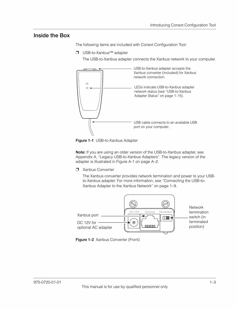
❐ USB-to-Xanbus™ adapter
The USB-to-Xanbus adapter connects the Xanbus network to your computer.
Note: If you are using an older version of the USB-to-Xanbus adapter, see Appendix A, “Legacy USB-to-Xanbus Adapters”. The legacy version of the adapter is illustrated in Figure A-1 on page A–2.
❐ Xanbus Converter
The Xanbus converter provides network termination and power to your USB-to-Xanbus adapter. For more information, see “Connecting the USB-to-Xanbus Adapter to the Xanbus Network” on page 1–9.
Figure 1-1 USB-to-Xanbus Adapter
USB-to-Xanbus adapter accepts the Xanbus converter (included) for Xanbus network connection.
LEDs indicate USB-to-Xanbus adapter network status (see “USB-to-Xanbus Adapter Status” on page 1–15).
USB cable connects to an available USB port on your computer.
Figure 1-2 Xanbus Converter (Front)
Xanbus port
Network terminationswitch (in
DC 12V foroptional AC adapter
terminatedposition)
975-0720-01-01 1–3This manual is for use by qualified personnel only
Introduction and Installation
❐ Xanbus network cable (14 ft./4.25 m)
❐ Installation USB flash drive, containing the following files:
• “Read Me” text file
• USB-to-Xanbus adapter driver software
• Conext Configuration Tool software
• Conext Configuration Tool Owner’s Guide PDF file (this manual)
• Release notes
• Legacy USB-to-Xanbus adapter driver software for older dongles
Power supply for USB-to-Xanbus adapter
The USB-to-Xanbus adapter is powered by the Xanbus network and your computer’s USB port. If your installation requires an external power supply for the USB-to-Xanbus adapter, compatible power adapters are available.
Schneider Electric recommends the following AC adapter for use with Conext Configuration Tool:
• EMSA120150-P5P-SZ Wall Adapter (with interchangeable AC blades)Schneider Electric Part Number: 0J-921-0023-Z
For more information, contact your local Schneider Electric Sales Representative.
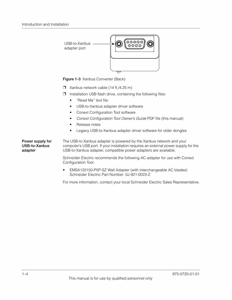
Figure 1-3 Xanbus Converter (Back)
USB-to-Xanbusadapter port
1–4 975-0720-01-01This manual is for use by qualified personnel only
Installing Conext Configuration Tool
Installing Conext Configuration ToolTo install Conext Configuration Tool, you will need to perform all of the following steps:
1. Install the USB-to-Xanbus adapter driver software on your computer.
2. Connect the USB-to-Xanbus adapter to your computer.
3. Configure the USB-to-Xanbus adapter driver software.
Note: Perform step 3 before running Conext Configuration Tool for the first time.
4. Connect the USB-to-Xanbus adapter to the Xanbus network.
5. Install the Conext Configuration Tool software on your computer.
Installing the USB-to-Xanbus Adapter Driver Software
Before you connect the USB-to-Xanbus adapter, you must install the driver software.
To install the USB-to-Xanbus adapter driver software:
1. Insert the Installation USB flash drive into an available USB port on your computer.
Note: Ensure that you are logged in with administrator privileges and that Windows Explorer shows all file extensions.
2. Open Windows Explorer or equivalent file browser and navigate to the Installation USB flash drive.
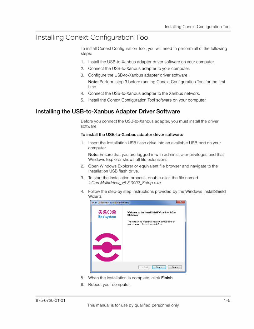
3. To start the installation process, double-click the file named isCan Multidriver_v5.3.0002_Setup.exe.
4. Follow the step-by step instructions provided by the Windows InstallShield Wizard.
5. When the installation is complete, click Finish.
6. Reboot your computer.
975-0720-01-01 1–5This manual is for use by qualified personnel only
Introduction and Installation
Connecting the USB-to-Xanbus Adapter to Your Computer
To connect the USB-to-Xanbus adapter:
1. Connect the built-in USB cable of the USB-to-Xanbus adapter to an available USB port on your computer.
2. When it is connected, a green LED indicates the presence of the operating voltage and flashes during the start-up/reset process.
Note: A red LED indicates an error during start-up/reset by flashing three times.
3. If a “Found New Hardware” message or Wizard appears in the status area of your desktop, close it.
4. Proceed to “Configuring the USB-to-Xanbus Adapter Driver Software”.
Configuring the USB-to-Xanbus Adapter Driver Software
Before you can operate Conext Configuration Tool, you must configure the USB-to-Xanbus adapter driver software.
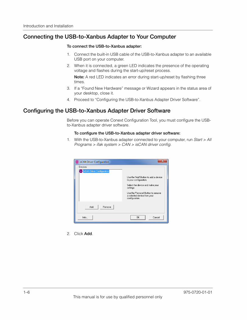
To configure the USB-to-Xanbus adapter driver software:
1. With the USB-to-Xanbus adapter connected to your computer, run Start > All Programs > ifak system > CAN > isCAN driver config.
2. Click Add.
1–6 975-0720-01-01This manual is for use by qualified personnel only
Installing Conext Configuration Tool
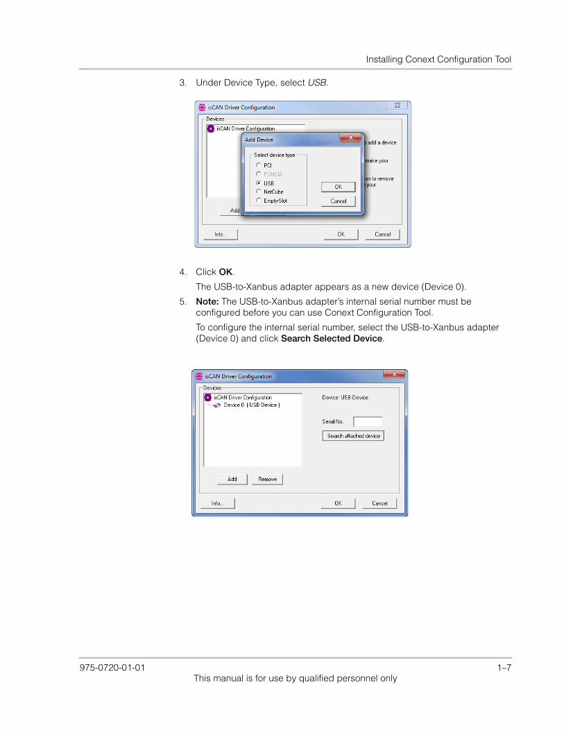
3. Under Device Type, select USB.
4. Click OK.
The USB-to-Xanbus adapter appears as a new device (Device 0).
5. Note: The USB-to-Xanbus adapter’s internal serial number must be configured before you can use Conext Configuration Tool.
To configure the internal serial number, select the USB-to-Xanbus adapter (Device 0) and click Search Selected Device.
975-0720-01-01 1–7This manual is for use by qualified personnel only

Introduction and Installation
6. The internal serial number of the USB-to-Xanbus adapter appears in the Serial No. field.
Note: Your USB-to-Xanbus adapter will have a unique serial number, different from the one shown above. The serial number should match the label on the back of the dongle hardware.
7. Click OK.
The USB-to-Xanbus adapter is now ready to be connected to the Xanbus network.
1–8 975-0720-01-01This manual is for use by qualified personnel only
Installing Conext Configuration Tool
Connecting the USB-to-Xanbus Adapter to the Xanbus Network
To connect the USB-to-Xanbus adapter to the Xanbus network:
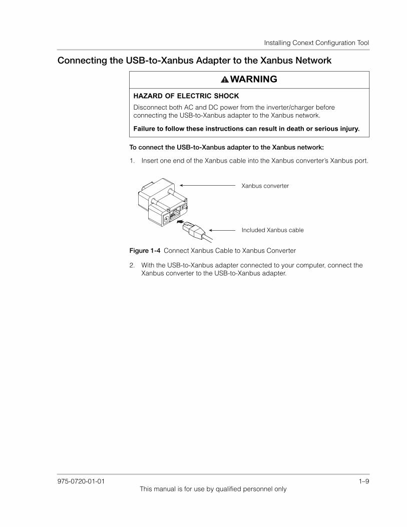
1. Insert one end of the Xanbus cable into the Xanbus converter’s Xanbus port.
2. With the USB-to-Xanbus adapter connected to your computer, connect the Xanbus converter to the USB-to-Xanbus adapter.
WARNING
HAZARD OF ELECTRIC SHOCK
Disconnect both AC and DC power from the inverter/charger before connecting the USB-to-Xanbus adapter to the Xanbus network.
Failure to follow these instructions can result in death or serious injury.
Figure 1-4 Connect Xanbus Cable to Xanbus Converter
Xanbus converter
Included Xanbus cable
975-0720-01-01 1–9This manual is for use by qualified personnel only

Introduction and Installation
Note: Ensure that the USB-to-Xanbus adapter pins are properly aligned with the Xanbus converter pin holes before tightening the Xanbus converter screws.
3. Connect the other end of the Xanbus cable to an open port on the Xanbus network. (See Figure 1-6 on page 1–11 for an example of a Xanbus network with the USB-to-Xanbus adapter connected.)
Note: The Xanbus network must be terminated at both ends. The USB-to-Xanbus adapter has a built-in termination feature, activated by a switch on the Xanbus converter. For more information, see “Network termination” on page 1–11.
4. Reconnect AC and DC power to the inverter/charger and power back on as necessary.
Figure 1-5 Connect Xanbus Converter to USB-to-Xanbus Adapter
Xanbus converter
USB-to-Xanbusadapter
Included Xanbus cable
1–10 975-0720-01-01This manual is for use by qualified personnel only

Installing Conext Configuration Tool
Network termination
The Xanbus network must be terminated at both ends. If you need to remove a network terminator from the Xanbus network in order to add the USB-to-Xanbus adapter to the network, ensure that the Xanbus converter’s network termination switch is in the “on” position.
Figure 1-6 Connect USB-to-Xanbus Adapter to Xanbus Network
AC1
AC2
Event
Equalize
kW
ACharging
!
Inverting
StandbyEvent/Warning
Conext XW SCP
Chargecontroller
Inverter/Charger
AGS SCP
Network
To computerUSB port
USB-to-Xanbusadapter
Xanbuscable
terminator
Figure 1-7 Network Termination Switch
Network terminationswitch (in terminatedpositin)
975-0720-01-01 1–11This manual is for use by qualified personnel only
Introduction and Installation
Installing the Conext Configuration Tool Software
To install the Conext Configuration Tool software:
1. With the Installation USB flash drive in the USB port, Open Windows Explorer or equivalent file browser and navigate to the Installation USB flash drive.
Note: Ensure that you are logged in with administrator privileges and that Windows Explorer shows all file extensions.
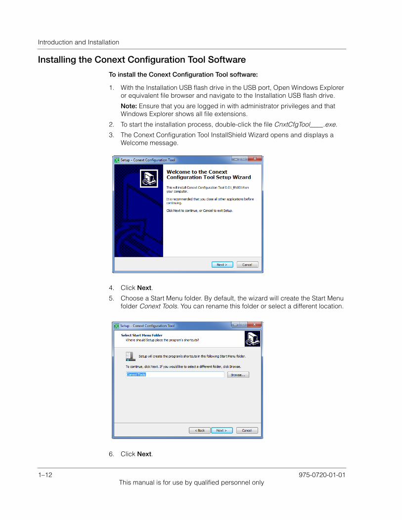
2. To start the installation process, double-click the file CnxtCfgTool____.exe.
3. The Conext Configuration Tool InstallShield Wizard opens and displays a Welcome message.
4. Click Next.
5. Choose a Start Menu folder. By default, the wizard will create the Start Menu folder Conext Tools. You can rename this folder or select a different location.
6. Click Next.
1–12 975-0720-01-01This manual is for use by qualified personnel only
Installing Conext Configuration Tool
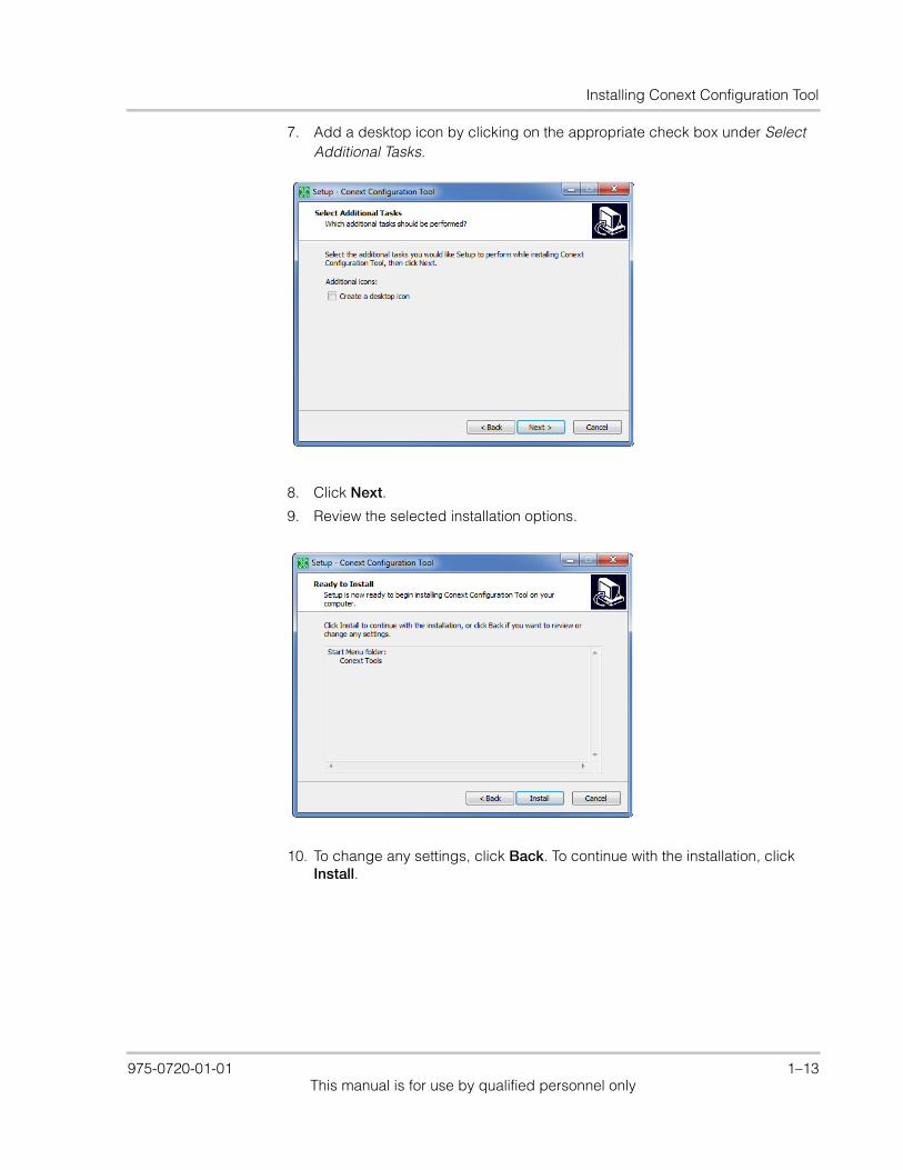
7. Add a desktop icon by clicking on the appropriate check box under Select Additional Tasks.
8. Click Next.
9. Review the selected installation options.
10. To change any settings, click Back. To continue with the installation, click Install.
975-0720-01-01 1–13This manual is for use by qualified personnel only
Introduction and Installation
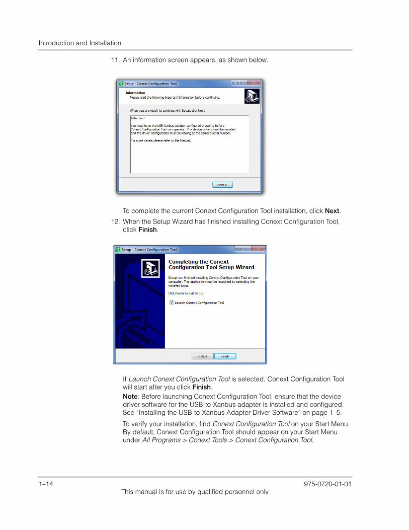
11. An information screen appears, as shown below.
To complete the current Conext Configuration Tool installation, click Next.
12. When the Setup Wizard has finished installing Conext Configuration Tool, click Finish.
If Launch Conext Configuration Tool is selected, Conext Configuration Tool will start after you click Finish.Note: Before launching Conext Configuration Tool, ensure that the device driver software for the USB-to-Xanbus adapter is installed and configured. See “Installing the USB-to-Xanbus Adapter Driver Software” on page 1–5.
To verify your installation, find Conext Configuration Tool on your Start Menu. By default, Conext Configuration Tool should appear on your Start Menu under All Programs > Conext Tools > Conext Configuration Tool.
1–14 975-0720-01-01This manual is for use by qualified personnel only
Operating Conext Configuration Tool
Operating Conext Configuration Tool
USB-to-Xanbus Adapter Status
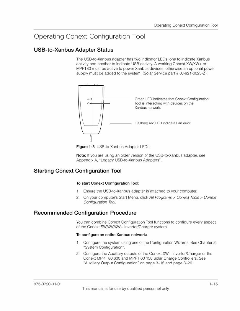
The USB-to-Xanbus adapter has two indicator LEDs, one to indicate Xanbus activity and another to indicate USB activity. A working Conext XW/XW+ or MPPT80 must be active to power Xanbus devices, otherwise an optional power supply must be added to the system. (Solar Service part # 0J-921-0023-Z).
Note: If you are using an older version of the USB-to-Xanbus adapter, see Appendix A, “Legacy USB-to-Xanbus Adapters”.
Starting Conext Configuration Tool
To start Conext Configuration Tool:
1. Ensure the USB-to-Xanbus adapter is attached to your computer.
2. On your computer’s Start Menu, click All Programs > Conext Tools > Conext Configuration Tool.
Recommended Configuration Procedure
You can combine Conext Configuration Tool functions to configure every aspect of the Conext SW/XW/XW+ Inverter/Charger system.
To configure an entire Xanbus network:
1. Configure the system using one of the Configuration Wizards. See Chapter 2, “System Configuration”.
2. Configure the Auxiliary outputs of the Conext XW+ Inverter/Charger or the Conext MPPT 80 600 and MPPT 60 150 Solar Charge Controllers. See “Auxiliary Output Configuration” on page 3–15 and page 3–26.
Figure 1-8 USB-to-Xanbus Adapter LEDs
Green LED indicates that Conext Configuration Tool is interacting with devices on the Xanbus network.
Flashing red LED indicates an error.
975-0720-01-01 1–15This manual is for use by qualified personnel only
Introduction and Installation
3. Configure the Conext Automatic Generator Start. See “Configuring the Conext Automatic Generator Start” on page 3–28.
4. Save the current configuration settings. See “Saving the System Configuration” on page 3–4.
Main Screen Features and Commands
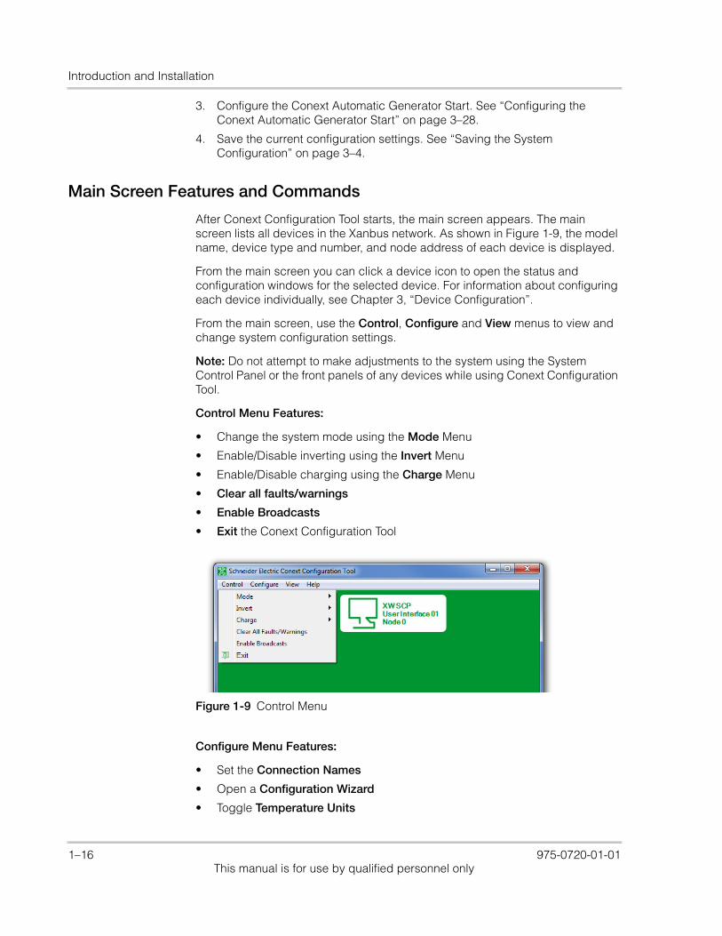
After Conext Configuration Tool starts, the main screen appears. The main screen lists all devices in the Xanbus network. As shown in Figure 1-9, the model name, device type and number, and node address of each device is displayed.
From the main screen you can click a device icon to open the status and configuration windows for the selected device. For information about configuring each device individually, see Chapter 3, “Device Configuration”.
From the main screen, use the Control, Configure and View menus to view and change system configuration settings.
Note: Do not attempt to make adjustments to the system using the System Control Panel or the front panels of any devices while using Conext Configuration Tool.
Control Menu Features:
• Change the system mode using the Mode Menu
• Enable/Disable inverting using the Invert Menu
• Enable/Disable charging using the Charge Menu
• Clear all faults/warnings
• Enable Broadcasts
• Exit the Conext Configuration Tool
Configure Menu Features:
• Set the Connection Names
• Open a Configuration Wizard
• Toggle Temperature Units
Figure 1-9 Control Menu
1–16 975-0720-01-01This manual is for use by qualified personnel only

Operating Conext Configuration Tool
• Perform Firmware Upgrades
• Convert Phase of your inverter (Conext XW+ Inverter/Chargers only)
• Save and Restore configuration settings
View Menu Features:
• View a detailed overview of the entire system with the System Map
• Log information with the Data Logger
Control Menu Features
Mode
To manually change the operating mode of the system using your computer, click Mode.
The two available modes are Operating and Standby. Standby mode is required when configuring the Xanbus network.
Starting the Configuration Wizard automatically puts the system into Standby mode. Exiting the Configuration Wizard returns the system to Operating mode.
Invert
Use this feature to enable or disable inverting on all applicable devices.
Figure 1-10 Configure Menu
Figure 1-11 View Menu
975-0720-01-01 1–17This manual is for use by qualified personnel only
Introduction and Installation
Charge
Use this feature to enable or disable charging on all applicable devices.
Clear All Faults/Warnings
To clear all system faults and warnings, click Clear All Faults/Warnings.
Enable Broadcasts
Use Enable Broadcasts to re-enable Xanbus network messages. See Chapter 5, “Upgrading Firmware”.
Exit
To quit Conext Configuration Tool, click Exit.
Configure Menu Features
Connection Names
If you have a Conext System Control Panel (SCP) on your Xanbus network, you can easily change the system connection names by using Connection Names.
Note: This feature is only available if an SCP is installed on your Xanbus network.
To set the connection names:
1. In the Configure menu, click Connection Names.
2. Click the tab for the type of association you wish to set (Grids, AC Loads, Generators, Batteries, or Solar Arrays).
1–18 975-0720-01-01This manual is for use by qualified personnel only
Operating Conext Configuration Tool
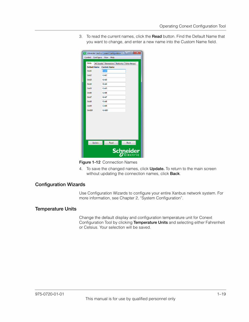
3. To read the current names, click the Read button. Find the Default Name that you want to change, and enter a new name into the Custom Name field.
4. To save the changed names, click Update. To return to the main screen without updating the connection names, click Back.
Configuration Wizards
Use Configuration Wizards to configure your entire Xanbus network system. For more information, see Chapter 2, “System Configuration”.
Temperature Units
Change the default display and configuration temperature unit for Conext Configuration Tool by clicking Temperature Units and selecting either Fahrenheit or Celsius. Your selection will be saved.
Figure 1-12 Connection Names
975-0720-01-01 1–19This manual is for use by qualified personnel only
Introduction and Installation
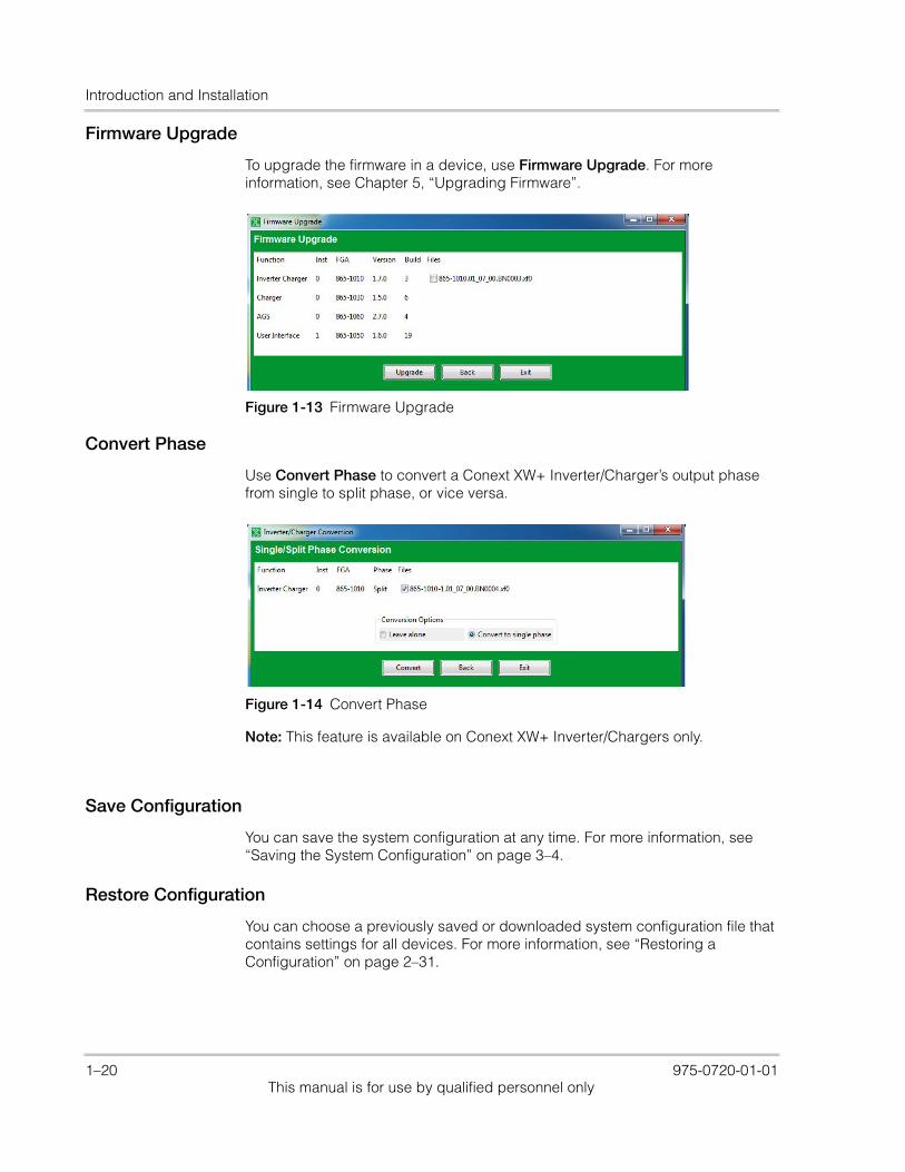
Firmware Upgrade
To upgrade the firmware in a device, use Firmware Upgrade. For more information, see Chapter 5, “Upgrading Firmware”.
Convert Phase
Use Convert Phase to convert a Conext XW+ Inverter/Charger’s output phase from single to split phase, or vice versa.
Note: This feature is available on Conext XW+ Inverter/Chargers only.
Save Configuration
You can save the system configuration at any time. For more information, see “Saving the System Configuration” on page 3–4.
Restore Configuration
You can choose a previously saved or downloaded system configuration file that contains settings for all devices. For more information, see “Restoring a Configuration” on page 2–31.
Figure 1-13 Firmware Upgrade
Figure 1-14 Convert Phase
1–20 975-0720-01-01This manual is for use by qualified personnel only

Operating Conext Configuration Tool
View Menu Functions
System Map
To view the System Map, go to the View menu and select System Map. Conext Configuration Tool indicates its progress as it collects association information from all the devices in the system, then displays the System Map.
The System Map shows all the devices in the system and their respective AC and DC connections.
Data Logger
To log selected data and store to file, send out as an e-mail, or transfer to an FTP site, click Log. For more information, see Chapter 4, “System Logging”.
Figure 1-15 System Map
975-0720-01-01 1–21This manual is for use by qualified personnel only

Introduction and Installation
1–22 975-0720-01-01This manual is for use by qualified personnel only
2 System Configuration
Chapter 2 contains information and procedures to configure a Conext XW+ Inverter/Charger system using the Conext Configuration Tool Configuration Wizards.
Topics in this chapter include:• “About the Configuration Wizards” on
page 2–2• “Guidelines for Configuration Wizards”
on page 2–2• “Using the Configuration Wizard” on
page 2–3• “Restoring a Configuration” on page 2–
31.
975-0720-01-01 2–1This manual is for use by qualified personnel only
System Configuration
About the Configuration WizardsThe Conext Configuration Tool Configuration Wizard offers three methods for configuring the system.
• Quick – The Quick Configuration Wizard is intended to get the system up and running quickly. It allows you to set Device Numbers, Connections, a System Master, and all inverter/charger and charge controller settings required for a working system. The Quick Configuration Wizard does not configure grid support or generator support.
• Detailed – The Detailed Configuration Wizard offers everything in the Quick Wizard, as well as Grid Support and Generator Support settings.
• Multi-Cluster – The Multi-Cluster Configuration Wizard offers everything in the Detailed Wizard, as well as advanced options for multi-cluster systems such as AC Associations, Advanced Battery Settings and Transfer Switch Configuration.
Restoring configuration from a saved file
You can also restore your configuration from a previously saved or downloaded system configuration file that contains settings for all devices. For more information, see “Restoring a Configuration” on page 2–31.
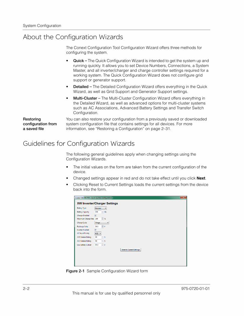
Guidelines for Configuration Wizards
The following general guidelines apply when changing settings using the Configuration Wizards.
• The initial values on the form are taken from the current configuration of the device.
• Changed settings appear in red and do not take effect until you click Next.
• Clicking Reset to Current Settings loads the current settings from the device back into the form.
Figure 2-1 Sample Configuration Wizard form
2–2 975-0720-01-01This manual is for use by qualified personnel only
Using the Configuration Wizard
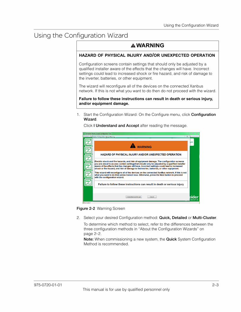
Using the Configuration Wizard
1. Start the Configuration Wizard: On the Configure menu, click Configuration Wizard.
Click I Understand and Accept after reading the message.
2. Select your desired Configuration method: Quick, Detailed or Multi-Cluster.
To determine which method to select, refer to the differences between the three configuration methods in “About the Configuration Wizards” on page 2–2.Note: When commissioning a new system, the Quick System Configuration Method is recommended.
WARNING
HAZARD OF PHYSICAL INJURY AND/OR UNEXPECTED OPERATION
Configuration screens contain settings that should only be adjusted by a qualified installer aware of the effects that the changes will have. Incorrect settings could lead to increased shock or fire hazard, and risk of damage to the inverter, batteries, or other equipment.
The wizard will reconfigure all of the devices on the connected Xanbus network. If this is not what you want to do then do not proceed with the wizard.
Failure to follow these instructions can result in death or serious injury, and/or equipment damage.
Figure 2-2 Warning Screen
975-0720-01-01 2–3This manual is for use by qualified personnel only
System Configuration
Quick Configuration Method
1. Reset devices to factory defaults:
After selecting the Quick configuration method, the Factory Defaults screen appears. When using the Configuration Wizard, it is recommended to set all devices to Factory Defaults. If there are customized settings you want to preserve, devices must be configured separately. See Chapter 3, “Device Configuration”.If you click the Reset all devices to factory defaults checkbox, then click Next, the system resets. This process takes about 20 seconds. During this time, the pointer changes to an hourglass and the Next button is unavailable. When the appearance of the pointer returns to normal and the Next button is available again, the reset has completed.
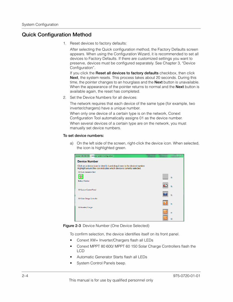
2. Set the Device Numbers for all devices:
The network requires that each device of the same type (for example, two inverter/chargers) have a unique number.When only one device of a certain type is on the network, Conext Configuration Tool automatically assigns 01 as the device number.When several devices of a certain type are on the network, you must manually set device numbers.
To set device numbers:
a) On the left side of the screen, right-click the device icon. When selected, the icon is highlighted green.
To confirm selection, the device identifies itself on its front panel.
• Conext XW+ Inverter/Chargers flash all LEDs
• Conext MPPT 80 600/ MPPT 60 150 Solar Charge Controllers flash the LCD
• Automatic Generator Starts flash all LEDs
• System Control Panels beep.
Figure 2-3 Device Number (One Device Selected)
2–4 975-0720-01-01This manual is for use by qualified personnel only
Using the Configuration Wizard
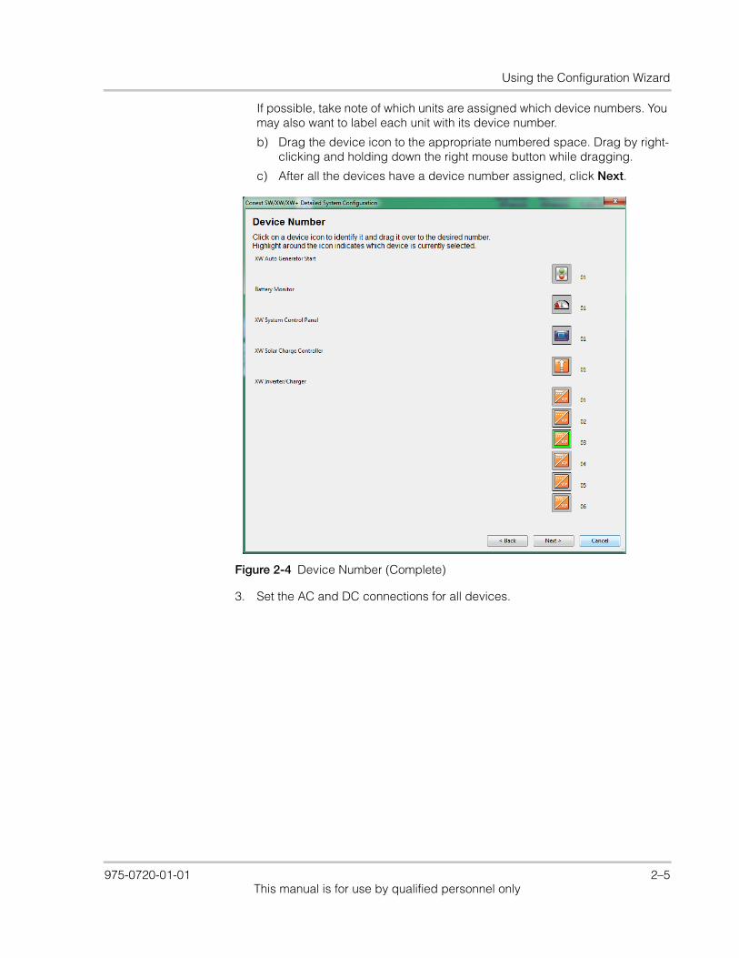
If possible, take note of which units are assigned which device numbers. You may also want to label each unit with its device number.
b) Drag the device icon to the appropriate numbered space. Drag by right-clicking and holding down the right mouse button while dragging.
c) After all the devices have a device number assigned, click Next.
3. Set the AC and DC connections for all devices.
Figure 2-4 Device Number (Complete)
975-0720-01-01 2–5This manual is for use by qualified personnel only
System Configuration
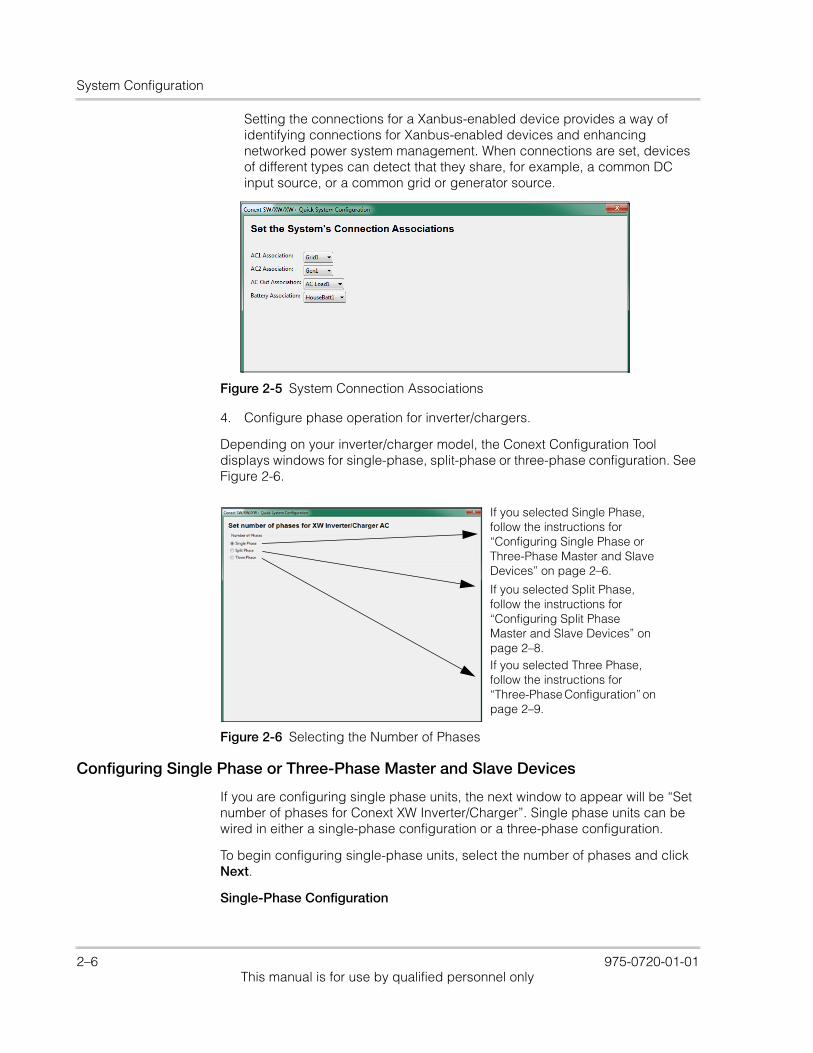
Setting the connections for a Xanbus-enabled device provides a way of identifying connections for Xanbus-enabled devices and enhancing networked power system management. When connections are set, devices of different types can detect that they share, for example, a common DC input source, or a common grid or generator source.
4. Configure phase operation for inverter/chargers.
Depending on your inverter/charger model, the Conext Configuration Tool displays windows for single-phase, split-phase or three-phase configuration. See Figure 2-6.
Configuring Single Phase or Three-Phase Master and Slave Devices
If you are configuring single phase units, the next window to appear will be “Set number of phases for Conext XW Inverter/Charger”. Single phase units can be wired in either a single-phase configuration or a three-phase configuration.
To begin configuring single-phase units, select the number of phases and click Next.
Single-Phase Configuration
Figure 2-5 System Connection Associations
Figure 2-6 Selecting the Number of Phases
If you selected Single Phase, follow the instructions for “Configuring Single Phase or Three-Phase Master and Slave Devices” on page 2–6.
If you selected Three Phase, follow the instructions for “Three-Phase Configuration” on page 2–9.
If you selected Split Phase, follow the instructions for “Configuring Split Phase Master and Slave Devices” on page 2–8.
2–6 975-0720-01-01This manual is for use by qualified personnel only
Using the Configuration Wizard
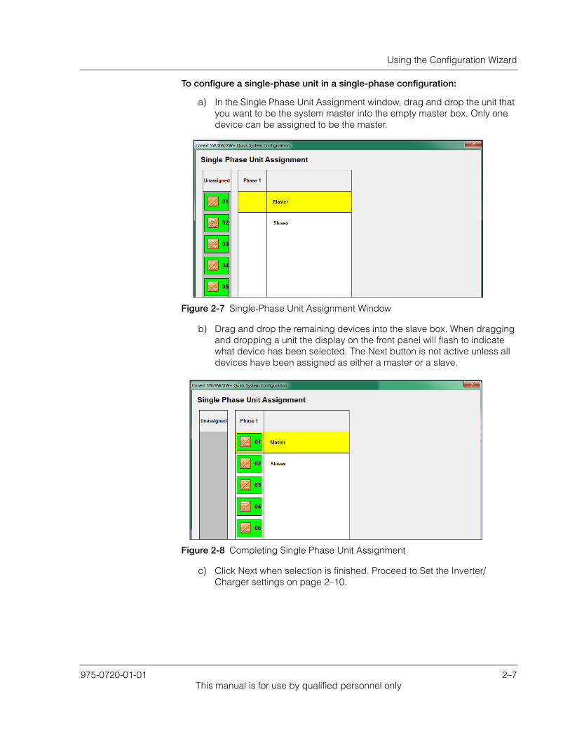
To configure a single-phase unit in a single-phase configuration:
a) In the Single Phase Unit Assignment window, drag and drop the unit that you want to be the system master into the empty master box. Only one device can be assigned to be the master.
b) Drag and drop the remaining devices into the slave box. When dragging and dropping a unit the display on the front panel will flash to indicate what device has been selected. The Next button is not active unless all devices have been assigned as either a master or a slave.
c) Click Next when selection is finished. Proceed to Set the Inverter/Charger settings on page 2–10.
Figure 2-7 Single-Phase Unit Assignment Window
Figure 2-8 Completing Single Phase Unit Assignment
975-0720-01-01 2–7This manual is for use by qualified personnel only
System Configuration
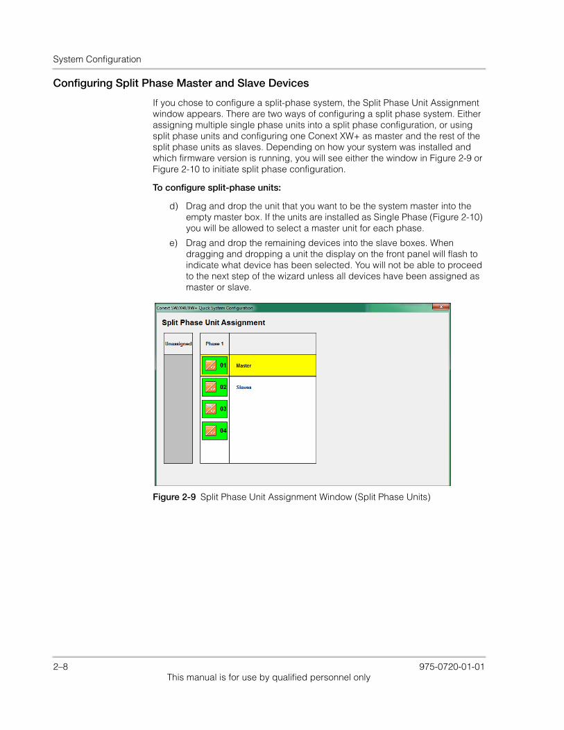
Configuring Split Phase Master and Slave Devices
If you chose to configure a split-phase system, the Split Phase Unit Assignment window appears. There are two ways of configuring a split phase system. Either assigning multiple single phase units into a split phase configuration, or using split phase units and configuring one Conext XW+ as master and the rest of the split phase units as slaves. Depending on how your system was installed and which firmware version is running, you will see either the window in Figure 2-9 or Figure 2-10 to initiate split phase configuration.
To configure split-phase units:
d) Drag and drop the unit that you want to be the system master into the empty master box. If the units are installed as Single Phase (Figure 2-10) you will be allowed to select a master unit for each phase.
e) Drag and drop the remaining devices into the slave boxes. When dragging and dropping a unit the display on the front panel will flash to indicate what device has been selected. You will not be able to proceed to the next step of the wizard unless all devices have been assigned as master or slave.
Figure 2-9 Split Phase Unit Assignment Window (Split Phase Units)
2–8 975-0720-01-01This manual is for use by qualified personnel only
Using the Configuration Wizard
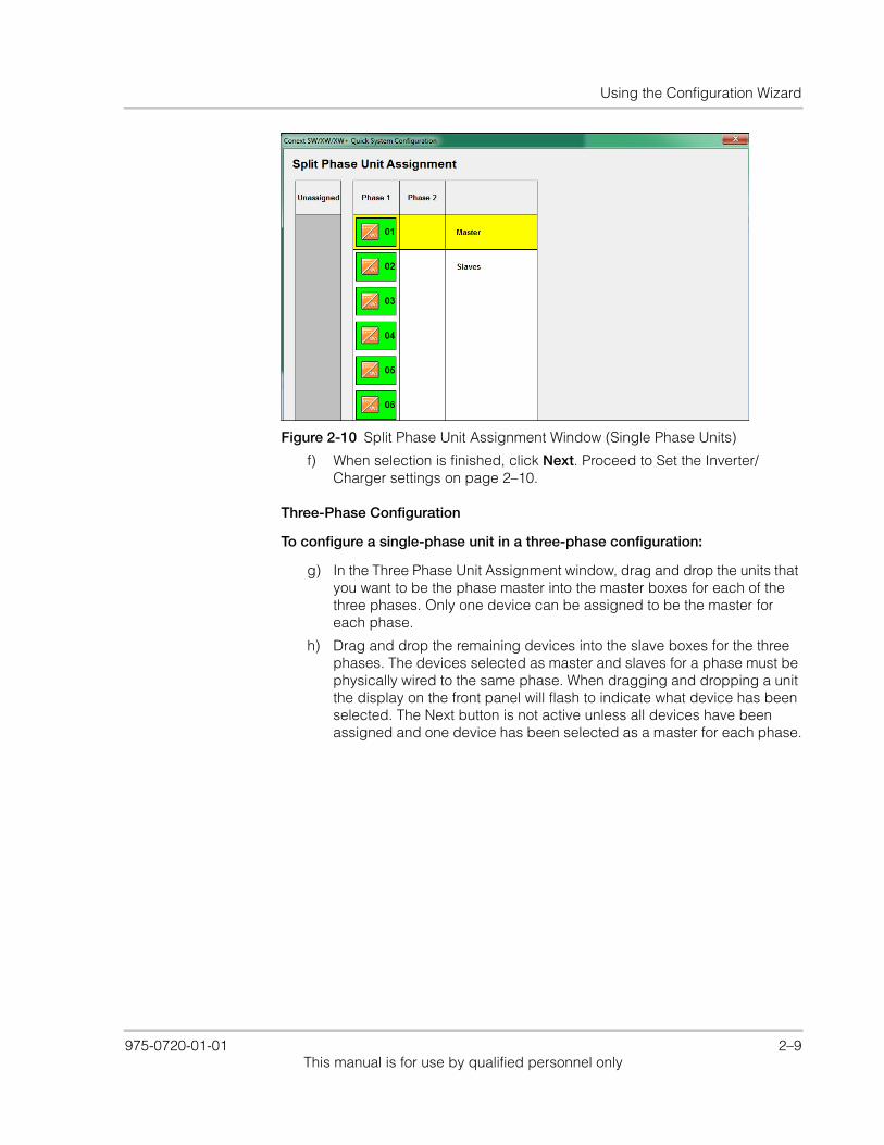
f) When selection is finished, click Next. Proceed to Set the Inverter/Charger settings on page 2–10.
Three-Phase Configuration
To configure a single-phase unit in a three-phase configuration:
g) In the Three Phase Unit Assignment window, drag and drop the units that you want to be the phase master into the master boxes for each of the three phases. Only one device can be assigned to be the master for each phase.
h) Drag and drop the remaining devices into the slave boxes for the three phases. The devices selected as master and slaves for a phase must be physically wired to the same phase. When dragging and dropping a unit the display on the front panel will flash to indicate what device has been selected. The Next button is not active unless all devices have been assigned and one device has been selected as a master for each phase.
Figure 2-10 Split Phase Unit Assignment Window (Single Phase Units)
975-0720-01-01 2–9This manual is for use by qualified personnel only

System Configuration
i) When selection is finished, click Next. Proceed to Set the Inverter/Charger settings on page 2–10.
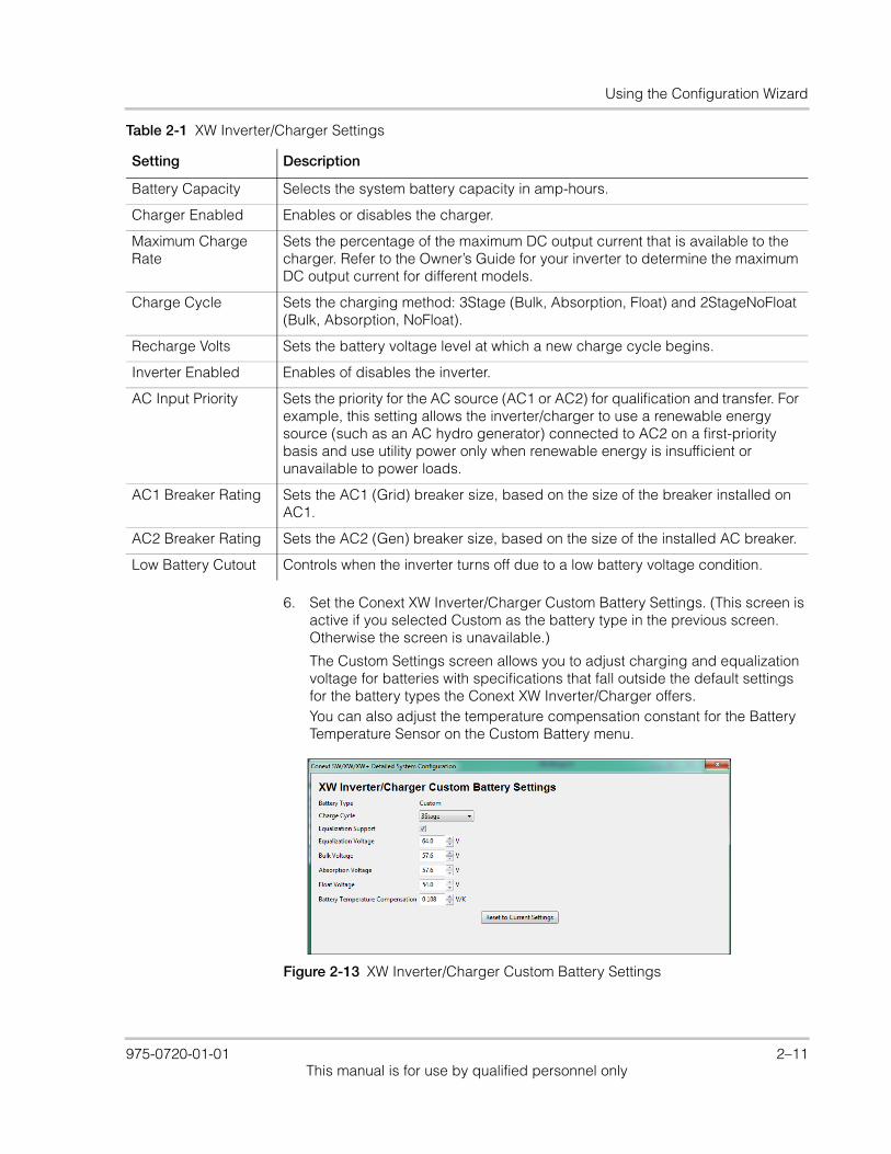
5. Set the XW Inverter/Charger settings.
The XW Inverter/Charger settings include basic battery and battery charger settings.
Figure 2-11 Completing Three Phase Unit Assignment
Figure 2-12 XW Inverter/Charger Settings
Table 2-1 XW Inverter/Charger Settings
Setting Description
Battery Type Selects the system battery chemistry and type: Flooded (default), AGM, Gel, Lithium Ion and Custom.
If you select Custom, a screen for configuring voltage settings for each charging stage is displayed after you click Next.
2–10 975-0720-01-01This manual is for use by qualified personnel only
Using the Configuration Wizard
6. Set the Conext XW Inverter/Charger Custom Battery Settings. (This screen is active if you selected Custom as the battery type in the previous screen. Otherwise the screen is unavailable.)
The Custom Settings screen allows you to adjust charging and equalization voltage for batteries with specifications that fall outside the default settings for the battery types the Conext XW Inverter/Charger offers.You can also adjust the temperature compensation constant for the Battery Temperature Sensor on the Custom Battery menu.
Battery Capacity Selects the system battery capacity in amp-hours.
Charger Enabled Enables or disables the charger.
Maximum Charge Rate
Sets the percentage of the maximum DC output current that is available to the charger. Refer to the Owner’s Guide for your inverter to determine the maximum DC output current for different models.
Charge Cycle Sets the charging method: 3Stage (Bulk, Absorption, Float) and 2StageNoFloat (Bulk, Absorption, NoFloat).
Recharge Volts Sets the battery voltage level at which a new charge cycle begins.
Inverter Enabled Enables of disables the inverter.
AC Input Priority Sets the priority for the AC source (AC1 or AC2) for qualification and transfer. For example, this setting allows the inverter/charger to use a renewable energy source (such as an AC hydro generator) connected to AC2 on a first-priority basis and use utility power only when renewable energy is insufficient or unavailable to power loads.
AC1 Breaker Rating Sets the AC1 (Grid) breaker size, based on the size of the breaker installed on AC1.
AC2 Breaker Rating Sets the AC2 (Gen) breaker size, based on the size of the installed AC breaker.
Low Battery Cutout Controls when the inverter turns off due to a low battery voltage condition.
Table 2-1 XW Inverter/Charger Settings
Setting Description
Figure 2-13 XW Inverter/Charger Custom Battery Settings
975-0720-01-01 2–11This manual is for use by qualified personnel only
System Configuration
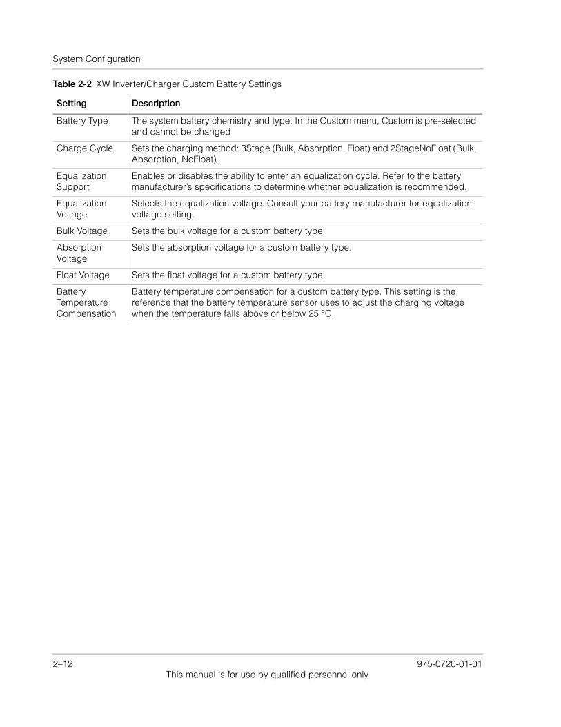
Table 2-2 XW Inverter/Charger Custom Battery Settings
Setting Description
Battery Type The system battery chemistry and type. In the Custom menu, Custom is pre-selected and cannot be changed
Charge Cycle Sets the charging method: 3Stage (Bulk, Absorption, Float) and 2StageNoFloat (Bulk, Absorption, NoFloat).
Equalization Support
Enables or disables the ability to enter an equalization cycle. Refer to the battery manufacturer’s specifications to determine whether equalization is recommended.
Equalization Voltage
Selects the equalization voltage. Consult your battery manufacturer for equalization voltage setting.
Bulk Voltage Sets the bulk voltage for a custom battery type.
Absorption Voltage
Sets the absorption voltage for a custom battery type.
Float Voltage Sets the float voltage for a custom battery type.
Battery Temperature Compensation
Battery temperature compensation for a custom battery type. This setting is the reference that the battery temperature sensor uses to adjust the charging voltage when the temperature falls above or below 25 °C.
2–12 975-0720-01-01This manual is for use by qualified personnel only
Using the Configuration Wizard
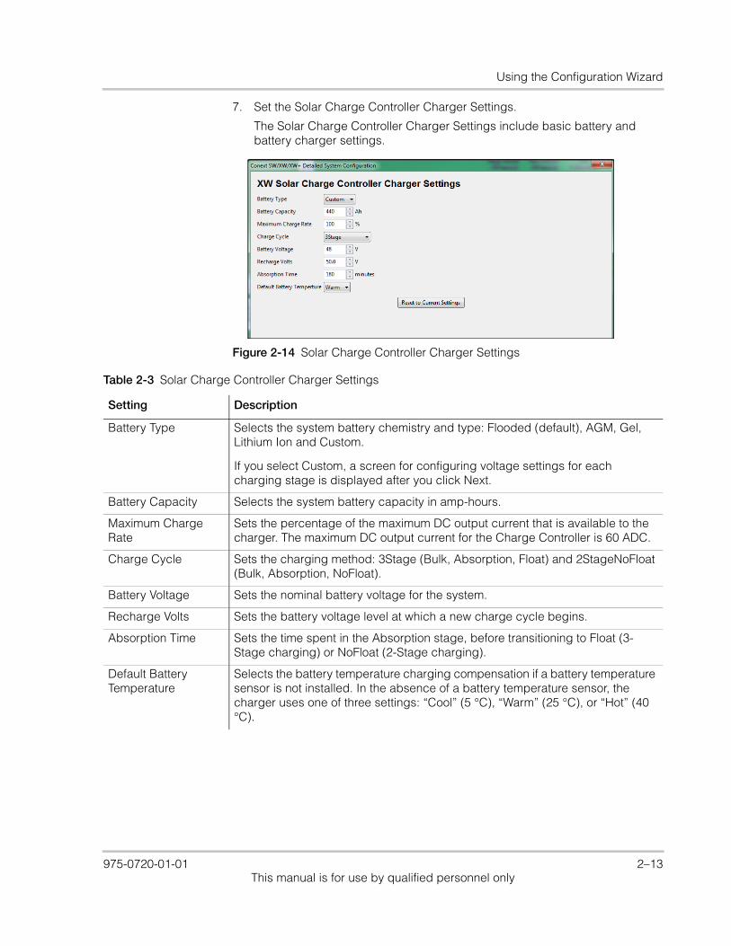
7. Set the Solar Charge Controller Charger Settings.
The Solar Charge Controller Charger Settings include basic battery and battery charger settings.
Figure 2-14 Solar Charge Controller Charger Settings
Table 2-3 Solar Charge Controller Charger Settings
Setting Description
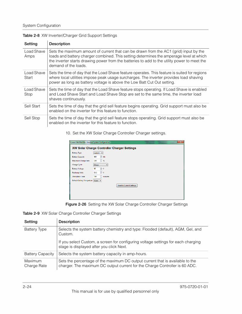
Battery Type Selects the system battery chemistry and type: Flooded (default), AGM, Gel, Lithium Ion and Custom.
If you select Custom, a screen for configuring voltage settings for each charging stage is displayed after you click Next.
Battery Capacity Selects the system battery capacity in amp-hours.
Maximum Charge Rate
Sets the percentage of the maximum DC output current that is available to the charger. The maximum DC output current for the Charge Controller is 60 ADC.
Charge Cycle Sets the charging method: 3Stage (Bulk, Absorption, Float) and 2StageNoFloat (Bulk, Absorption, NoFloat).
Battery Voltage Sets the nominal battery voltage for the system.
Recharge Volts Sets the battery voltage level at which a new charge cycle begins.
Absorption Time Sets the time spent in the Absorption stage, before transitioning to Float (3-Stage charging) or NoFloat (2-Stage charging).
Default Battery Temperature
Selects the battery temperature charging compensation if a battery temperature sensor is not installed. In the absence of a battery temperature sensor, the charger uses one of three settings: “Cool” (5 °C), “Warm” (25 °C), or “Hot” (40 °C).
975-0720-01-01 2–13This manual is for use by qualified personnel only
System Configuration
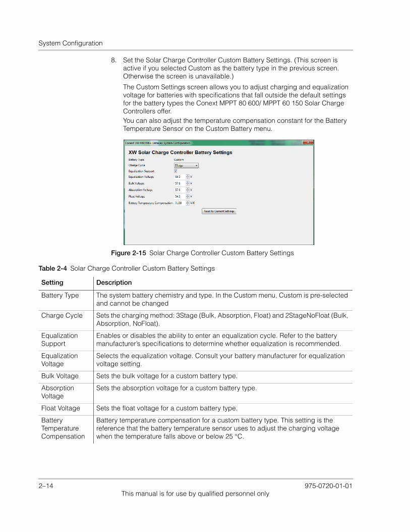
8. Set the Solar Charge Controller Custom Battery Settings. (This screen is active if you selected Custom as the battery type in the previous screen. Otherwise the screen is unavailable.)
The Custom Settings screen allows you to adjust charging and equalization voltage for batteries with specifications that fall outside the default settings for the battery types the Conext MPPT 80 600/ MPPT 60 150 Solar Charge Controllers offer.You can also adjust the temperature compensation constant for the Battery Temperature Sensor on the Custom Battery menu.
Figure 2-15 Solar Charge Controller Custom Battery Settings
Table 2-4 Solar Charge Controller Custom Battery Settings
Setting Description
Battery Type The system battery chemistry and type. In the Custom menu, Custom is pre-selected and cannot be changed
Charge Cycle Sets the charging method: 3Stage (Bulk, Absorption, Float) and 2StageNoFloat (Bulk, Absorption, NoFloat).
Equalization Support
Enables or disables the ability to enter an equalization cycle. Refer to the battery manufacturer’s specifications to determine whether equalization is recommended.
Equalization Voltage
Selects the equalization voltage. Consult your battery manufacturer for equalization voltage setting.
Bulk Voltage Sets the bulk voltage for a custom battery type.
Absorption Voltage
Sets the absorption voltage for a custom battery type.
Float Voltage Sets the float voltage for a custom battery type.
Battery Temperature Compensation
Battery temperature compensation for a custom battery type. This setting is the reference that the battery temperature sensor uses to adjust the charging voltage when the temperature falls above or below 25 °C.
2–14 975-0720-01-01This manual is for use by qualified personnel only
Using the Configuration Wizard
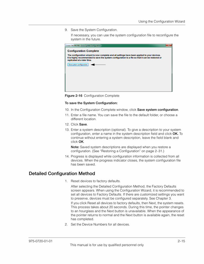
9. Save the System Configuration.
If necessary, you can use the system configuration file to reconfigure the system in the future.
To save the System Configuration:
10. In the Configuration Complete window, click Save system configuration.
11. Enter a file name. You can save the file to the default folder, or choose a different location.
12. Click Save.
13. Enter a system description (optional). To give a description to your system configuration, enter a name in the system description field and click OK. To continue without entering a system description, leave the field blank and click OK.
Note: Saved system descriptions are displayed when you restore a configuration. (See “Restoring a Configuration” on page 2–31.)
14. Progress is displayed while configuration information is collected from all devices. When the progress indicator closes, the system configuration file has been saved.
Detailed Configuration Method
1. Reset devices to factory defaults.
After selecting the Detailed Configuration Method, the Factory Defaults screen appears. When using the Configuration Wizard, it is recommended to set all devices to Factory Defaults. If there are customized settings you want to preserve, devices must be configured separately. See Chapter 3.If you click Reset all devices to factory defaults, then Next, the system resets. This process takes about 20 seconds. During this time, the pointer changes to an hourglass and the Next button is unavailable. When the appearance of the pointer returns to normal and the Next button is available again, the reset has completed.
2. Set the Device Numbers for all devices.
Figure 2-16 Configuration Complete
975-0720-01-01 2–15This manual is for use by qualified personnel only
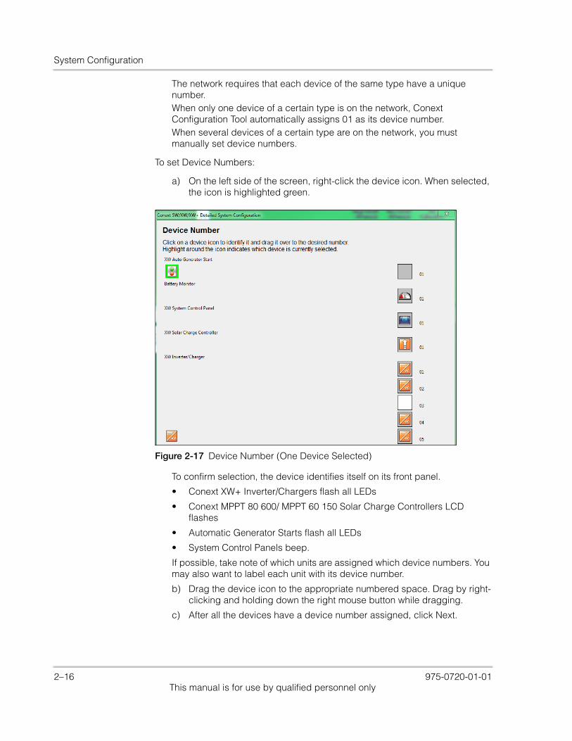
System Configuration
The network requires that each device of the same type have a unique number.When only one device of a certain type is on the network, Conext Configuration Tool automatically assigns 01 as its device number.When several devices of a certain type are on the network, you must manually set device numbers.
To set Device Numbers:
a) On the left side of the screen, right-click the device icon. When selected, the icon is highlighted green.
To confirm selection, the device identifies itself on its front panel.
• Conext XW+ Inverter/Chargers flash all LEDs
• Conext MPPT 80 600/ MPPT 60 150 Solar Charge Controllers LCD flashes
• Automatic Generator Starts flash all LEDs
• System Control Panels beep.
If possible, take note of which units are assigned which device numbers. You may also want to label each unit with its device number.
b) Drag the device icon to the appropriate numbered space. Drag by right-clicking and holding down the right mouse button while dragging.
c) After all the devices have a device number assigned, click Next.
Figure 2-17 Device Number (One Device Selected)
2–16 975-0720-01-01This manual is for use by qualified personnel only

Using the Configuration Wizard
3. Set the AC and DC connections for all devices.
Setting the connections for a Xanbus-enabled device provides a way of identifying connections for Xanbus-enabled devices and enhancing networked power system management. When connections are set, devices of different types can detect that they share, for example, a common DC input source, or a common grid or generator source.
4. Configure phase operation for inverter/chargers.
Depending on your inverter/charger model, the Conext Configuration Tool displays windows for single-phase, split-phase or three-phase configuration. See Figure 2-19.
When selection is finished, click Next. Proceed to Set the Inverter/Charger settings.
Figure 2-18 System Connection Associations
Figure 2-19 Selecting the Number of Phases
If you selected Single Phase, follow the instructions for “Configuring Single Phase or Three-Phase Master and Slave Devices” on page 2–6.
If you selected Three Phase, follow the instructions for “Three-Phase Configuration” on page 2–9.
If you selected Split Phase, follow the instructions for “Configuring Split Phase Master and Slave Devices” on page 2–8.
975-0720-01-01 2–17This manual is for use by qualified personnel only
System Configuration
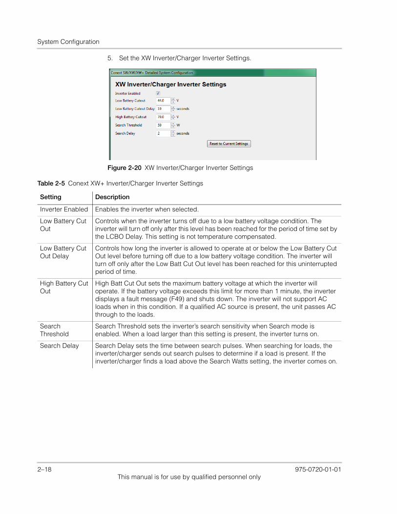
5. Set the XW Inverter/Charger Inverter Settings.
Figure 2-20 XW Inverter/Charger Inverter Settings
Table 2-5 Conext XW+ Inverter/Charger Inverter Settings
Setting Description
Inverter Enabled Enables the inverter when selected.
Low Battery Cut Out
Controls when the inverter turns off due to a low battery voltage condition. The inverter will turn off only after this level has been reached for the period of time set by the LCBO Delay. This setting is not temperature compensated.
Low Battery Cut Out Delay
Controls how long the inverter is allowed to operate at or below the Low Battery Cut Out level before turning off due to a low battery voltage condition. The inverter will turn off only after the Low Batt Cut Out level has been reached for this uninterrupted period of time.
High Battery Cut Out
High Batt Cut Out sets the maximum battery voltage at which the inverter will operate. If the battery voltage exceeds this limit for more than 1 minute, the inverter displays a fault message (F49) and shuts down. The inverter will not support AC loads when in this condition. If a qualified AC source is present, the unit passes AC through to the loads.
Search Threshold
Search Threshold sets the inverter’s search sensitivity when Search mode is enabled. When a load larger than this setting is present, the inverter turns on.
Search Delay Search Delay sets the time between search pulses. When searching for loads, the inverter/charger sends out search pulses to determine if a load is present. If the inverter/charger finds a load above the Search Watts setting, the inverter comes on.
2–18 975-0720-01-01This manual is for use by qualified personnel only

Using the Configuration Wizard
6. Set the XW Inverter/Charger Settings.
Figure 2-21 XW Inverter/Charger Settings
Table 2-6 XW Inverter/Charger Settings
Setting Description
Battery Type Selects the system battery chemistry and type: Flooded (default), AGM, Gel, Custom and Lithium Ion.
If you select Custom, a screen for configuring voltage settings for each charging stage is displayed after you click Next.
Battery Capacity
Selects the system battery capacity in amp-hours.
Charger Enabled
Enables or disables the charger.
Maximum Charge Rate
Sets the percentage of the maximum DC output current that is available to the charger. Refer to the Owner’s Guide for your inverter to determine the maximum DC output current for different models.
Charge Cycle Sets the charging method: 3Stage (Bulk, Absorption, Float) and 2StageNoFloat (Bulk, Absorption, NoFloat), and CVCC.
Recharge Volts Sets the battery voltage level at which a new charge cycle begins.
Inverter Enabled
Enables the inverter when selected.
AC Input Priority
Sets the priority for the AC source (AC1 or AC2) for qualification and transfer. For example, this setting allows the inverter/charger to use a renewable energy source (such as an AC hydro generator) connected to AC2 on a first-priority basis and use utility power only when renewable energy is insufficient or unavailable to power loads.
975-0720-01-01 2–19This manual is for use by qualified personnel only
System Configuration
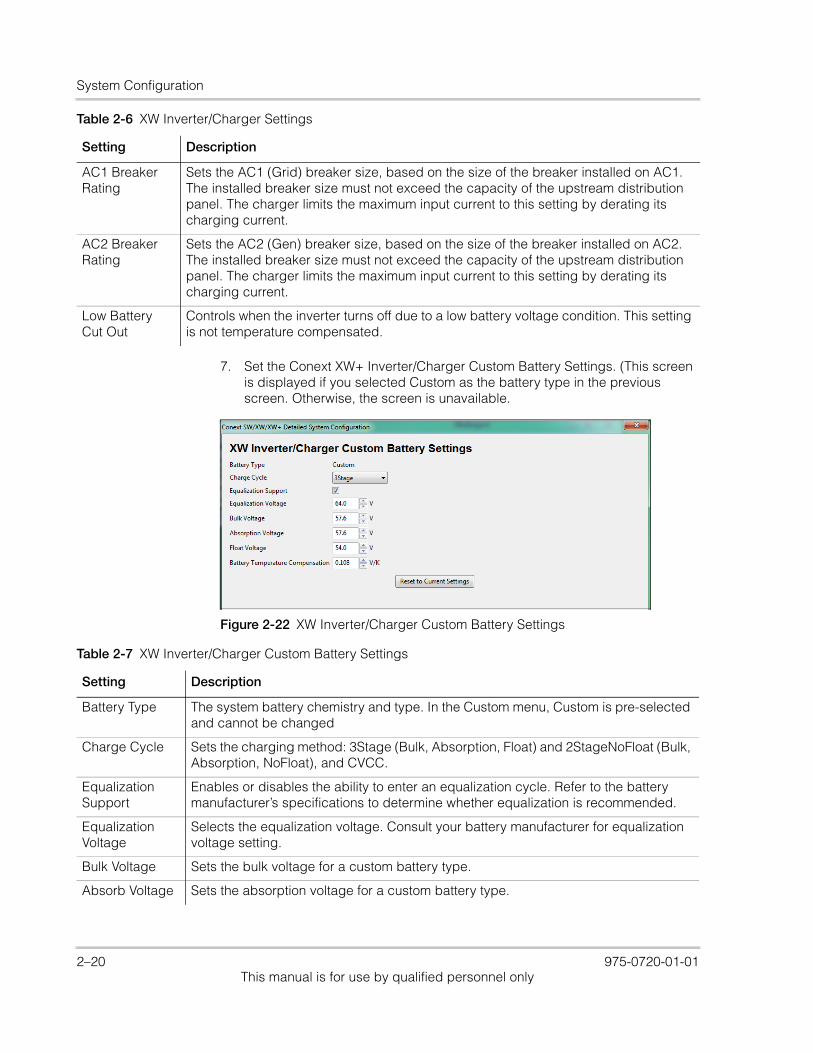
7. Set the Conext XW+ Inverter/Charger Custom Battery Settings. (This screen is displayed if you selected Custom as the battery type in the previous screen. Otherwise, the screen is unavailable.
AC1 Breaker Rating
Sets the AC1 (Grid) breaker size, based on the size of the breaker installed on AC1. The installed breaker size must not exceed the capacity of the upstream distribution panel. The charger limits the maximum input current to this setting by derating its charging current.
AC2 Breaker Rating
Sets the AC2 (Gen) breaker size, based on the size of the breaker installed on AC2. The installed breaker size must not exceed the capacity of the upstream distribution panel. The charger limits the maximum input current to this setting by derating its charging current.
Low Battery Cut Out
Controls when the inverter turns off due to a low battery voltage condition. This setting is not temperature compensated.
Table 2-6 XW Inverter/Charger Settings
Setting Description
Figure 2-22 XW Inverter/Charger Custom Battery Settings
Table 2-7 XW Inverter/Charger Custom Battery Settings
Setting Description
Battery Type The system battery chemistry and type. In the Custom menu, Custom is pre-selected and cannot be changed
Charge Cycle Sets the charging method: 3Stage (Bulk, Absorption, Float) and 2StageNoFloat (Bulk, Absorption, NoFloat), and CVCC.
Equalization Support
Enables or disables the ability to enter an equalization cycle. Refer to the battery manufacturer’s specifications to determine whether equalization is recommended.
Equalization Voltage
Selects the equalization voltage. Consult your battery manufacturer for equalization voltage setting.
Bulk Voltage Sets the bulk voltage for a custom battery type.
Absorb Voltage Sets the absorption voltage for a custom battery type.
2–20 975-0720-01-01This manual is for use by qualified personnel only
Using the Configuration Wizard
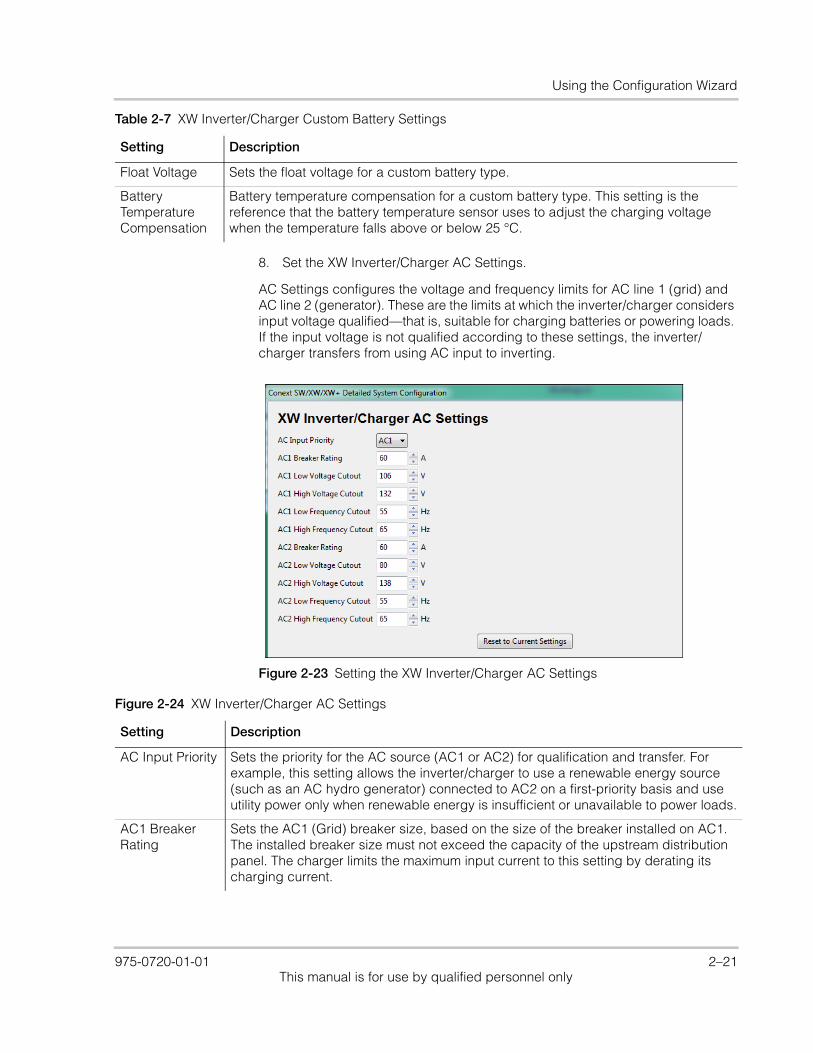
8. Set the XW Inverter/Charger AC Settings.
AC Settings configures the voltage and frequency limits for AC line 1 (grid) and AC line 2 (generator). These are the limits at which the inverter/charger considers input voltage qualified—that is, suitable for charging batteries or powering loads. If the input voltage is not qualified according to these settings, the inverter/charger transfers from using AC input to inverting.
Float Voltage Sets the float voltage for a custom battery type.
Battery Temperature Compensation
Battery temperature compensation for a custom battery type. This setting is the reference that the battery temperature sensor uses to adjust the charging voltage when the temperature falls above or below 25 °C.
Table 2-7 XW Inverter/Charger Custom Battery Settings
Setting Description
Figure 2-23 Setting the XW Inverter/Charger AC Settings
Figure 2-24 XW Inverter/Charger AC Settings
Setting Description
AC Input Priority Sets the priority for the AC source (AC1 or AC2) for qualification and transfer. For example, this setting allows the inverter/charger to use a renewable energy source (such as an AC hydro generator) connected to AC2 on a first-priority basis and use utility power only when renewable energy is insufficient or unavailable to power loads.
AC1 Breaker Rating
Sets the AC1 (Grid) breaker size, based on the size of the breaker installed on AC1. The installed breaker size must not exceed the capacity of the upstream distribution panel. The charger limits the maximum input current to this setting by derating its charging current.
975-0720-01-01 2–21This manual is for use by qualified personnel only
System Configuration
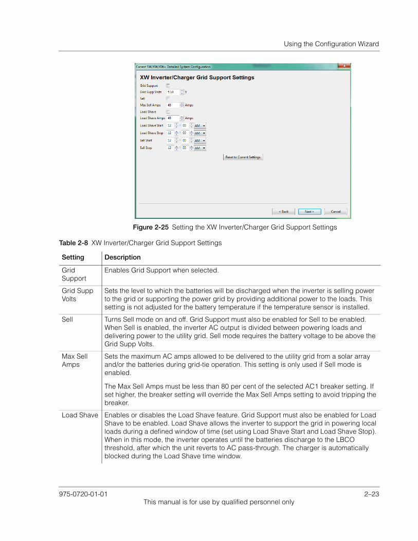
9. Set the XW Inverter/Charger Grid Support Settings.
The Grid Support Settings screen configures options for grid-tie operation.
AC1 Low Voltage Cutout
Minimum acceptable input voltage level from the utility grid.
AC1 High Voltage Cutout
Maximum acceptable input voltage level from the utility grid.
AC1 Low Frequency Cutout
Minimum acceptable utility grid input frequency.
AC1 High Frequency Cutout
Maximum acceptable utility grid input frequency.
AC2 Breaker Rating
Sets the AC2 (Gen) breaker size, based on the size of the installed AC breaker. The breaker size must not exceed the capacity of the generator. The charger limits the maximum input current to this setting by derating its charging current.
AC2 Low Voltage Cutout
Minimum acceptable input voltage level from the generator.
AC2 High Voltage Cutout
Maximum acceptable input voltage level from the generator.
AC2 Low Frequency Cutout
Minimum acceptable generator input frequency.
AC2 High Frequency Cutout
Maximum acceptable generator input frequency.
Figure 2-24 XW Inverter/Charger AC Settings
Setting Description
2–22 975-0720-01-01This manual is for use by qualified personnel only
Using the Configuration Wizard
Figure 2-25 Setting the XW Inverter/Charger Grid Support Settings
Table 2-8 XW Inverter/Charger Grid Support Settings
Setting Description
Grid Support
Enables Grid Support when selected.
Grid Supp Volts
Sets the level to which the batteries will be discharged when the inverter is selling power to the grid or supporting the power grid by providing additional power to the loads. This setting is not adjusted for the battery temperature if the temperature sensor is installed.
Sell Turns Sell mode on and off. Grid Support must also be enabled for Sell to be enabled. When Sell is enabled, the inverter AC output is divided between powering loads and delivering power to the utility grid. Sell mode requires the battery voltage to be above the Grid Supp Volts.
Max Sell Amps
Sets the maximum AC amps allowed to be delivered to the utility grid from a solar array and/or the batteries during grid-tie operation. This setting is only used if Sell mode is enabled.
The Max Sell Amps must be less than 80 per cent of the selected AC1 breaker setting. If set higher, the breaker setting will override the Max Sell Amps setting to avoid tripping the breaker.
Load Shave Enables or disables the Load Shave feature. Grid Support must also be enabled for Load Shave to be enabled. Load Shave allows the inverter to support the grid in powering local loads during a defined window of time (set using Load Shave Start and Load Shave Stop). When in this mode, the inverter operates until the batteries discharge to the LBCO threshold, after which the unit reverts to AC pass-through. The charger is automatically blocked during the Load Shave time window.
975-0720-01-01 2–23This manual is for use by qualified personnel only
System Configuration
10. Set the XW Solar Charge Controller Charger settings.
Load Shave Amps
Sets the maximum amount of current that can be drawn from the AC1 (grid) input by the loads and battery charger combined. This setting determines the amperage level at which the inverter starts drawing power from the batteries to add to the utility power to meet the demand of the loads.
Load Shave Start
Sets the time of day that the Load Shave feature operates. This feature is suited for regions where local utilities impose peak usage surcharges. The inverter provides load shaving power as long as battery voltage is above the Low Batt Cut Out setting.
Load Shave Stop
Sets the time of day that the Load Shave feature stops operating. If Load Shave is enabled and Load Shave Start and Load Shave Stop are set to the same time, the inverter load shaves continuously.
Sell Start Sets the time of day that the grid sell feature begins operating. Grid support must also be enabled on the inverter for this feature to function.
Sell Stop Sets the time of day that the grid sell feature stops operating. Grid support must also be enabled on the inverter for this feature to function.
Table 2-8 XW Inverter/Charger Grid Support Settings
Setting Description
Figure 2-26 Setting the XW Solar Charge Controller Charger Settings
Table 2-9 XW Solar Charge Controller Charger Settings
Setting Description
Battery Type Selects the system battery chemistry and type: Flooded (default), AGM, Gel, and Custom.
If you select Custom, a screen for configuring voltage settings for each charging stage is displayed after you click Next.
Battery Capacity Selects the system battery capacity in amp-hours.
Maximum Charge Rate
Sets the percentage of the maximum DC output current that is available to the charger. The maximum DC output current for the Charge Controller is 60 ADC.
2–24 975-0720-01-01This manual is for use by qualified personnel only
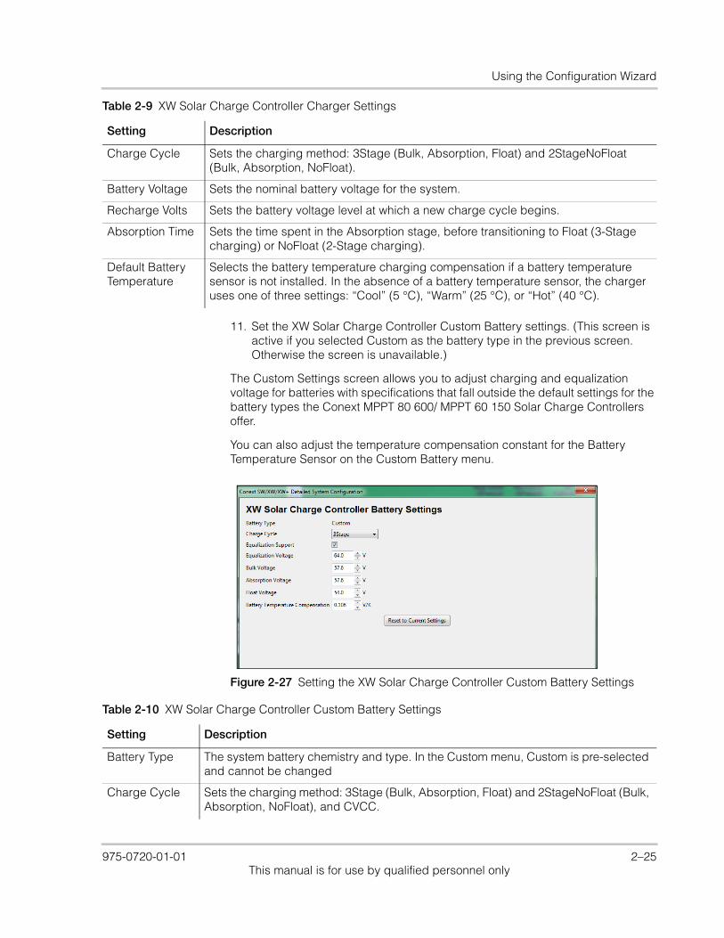
Using the Configuration Wizard
11. Set the XW Solar Charge Controller Custom Battery settings. (This screen is active if you selected Custom as the battery type in the previous screen. Otherwise the screen is unavailable.)
The Custom Settings screen allows you to adjust charging and equalization voltage for batteries with specifications that fall outside the default settings for the battery types the Conext MPPT 80 600/ MPPT 60 150 Solar Charge Controllers offer.
You can also adjust the temperature compensation constant for the Battery Temperature Sensor on the Custom Battery menu.
Charge Cycle Sets the charging method: 3Stage (Bulk, Absorption, Float) and 2StageNoFloat (Bulk, Absorption, NoFloat).
Battery Voltage Sets the nominal battery voltage for the system.
Recharge Volts Sets the battery voltage level at which a new charge cycle begins.
Absorption Time Sets the time spent in the Absorption stage, before transitioning to Float (3-Stage charging) or NoFloat (2-Stage charging).
Default Battery Temperature
Selects the battery temperature charging compensation if a battery temperature sensor is not installed. In the absence of a battery temperature sensor, the charger uses one of three settings: “Cool” (5 °C), “Warm” (25 °C), or “Hot” (40 °C).
Table 2-9 XW Solar Charge Controller Charger Settings
Setting Description
Figure 2-27 Setting the XW Solar Charge Controller Custom Battery Settings
Table 2-10 XW Solar Charge Controller Custom Battery Settings
Setting Description
Battery Type The system battery chemistry and type. In the Custom menu, Custom is pre-selected and cannot be changed
Charge Cycle Sets the charging method: 3Stage (Bulk, Absorption, Float) and 2StageNoFloat (Bulk, Absorption, NoFloat), and CVCC.
975-0720-01-01 2–25This manual is for use by qualified personnel only

System Configuration
12. Set the XW Solar Charge Controller Input Settings.
The input settings allow you to disable automatic maximum power point tracking and configure the reference voltage level the Conext MPPT Charge Controller operates from. Configuring the reference voltage is not required for normal operation, but can be useful for non-PV applications or for testing purposes.
13. Save the System Configuration. See “Save the System Configuration.” on page 2–15 for details.
Equalization Support
Enables or disables the ability to enter an equalization cycle. Refer to the battery manufacturer’s specifications to determine whether equalization is recommended.
Equalization Voltage
Selects the equalization voltage. Consult your battery manufacturer for equalization voltage setting.
Bulk Voltage Sets the bulk voltage for a custom battery type.
Absorption Voltage
Sets the absorption voltage for a custom battery type.
Float Voltage Sets the float voltage for a custom battery type.
Battery Temperature Compensation
Battery temperature compensation for a custom battery type. This setting is the reference that the battery temperature sensor uses to adjust the charging voltage when the temperature falls above or below 25 °C.
Table 2-10 XW Solar Charge Controller Custom Battery Settings
Setting Description
Figure 2-28 Setting the XW Solar Charge Controller Input Settings
Table 2-11 XW Solar Charge Controller Input Settings
Setting Description
Maximum Power Point Tracking
Enables (Auto) or disables (Manual) MPPT.
Static Reference Voltage
Selects the reference voltage the Charge Controller operates from when tracking is set to Manual.
2–26 975-0720-01-01This manual is for use by qualified personnel only
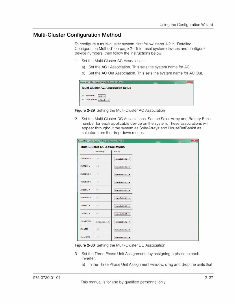
Using the Configuration Wizard
Multi-Cluster Configuration Method
To configure a multi-cluster system, first follow steps 1-2 in “Detailed Configuration Method” on page 2–15 to reset system devices and configure device numbers, then follow the instructions below.
1. Set the Multi-Cluster AC Association:
a) Set the AC1 Association. This sets the system name for AC1.
b) Set the AC Out Association. This sets the system name for AC Out.
2. Set the Multi-Cluster DC Associations. Set the Solar Array and Battery Bank number for each applicable device on the system. These associations will appear throughout the system as SolarArray# and HouseBatBank# as selected from the drop down menus.
3. Set the Three Phase Unit Assignments by assigning a phase to each Inverter:
a) In the Three Phase Unit Assignment window, drag and drop the units that
Figure 2-29 Setting the Multi-Cluster AC Association
Figure 2-30 Setting the Multi-Cluster DC Association
975-0720-01-01 2–27This manual is for use by qualified personnel only
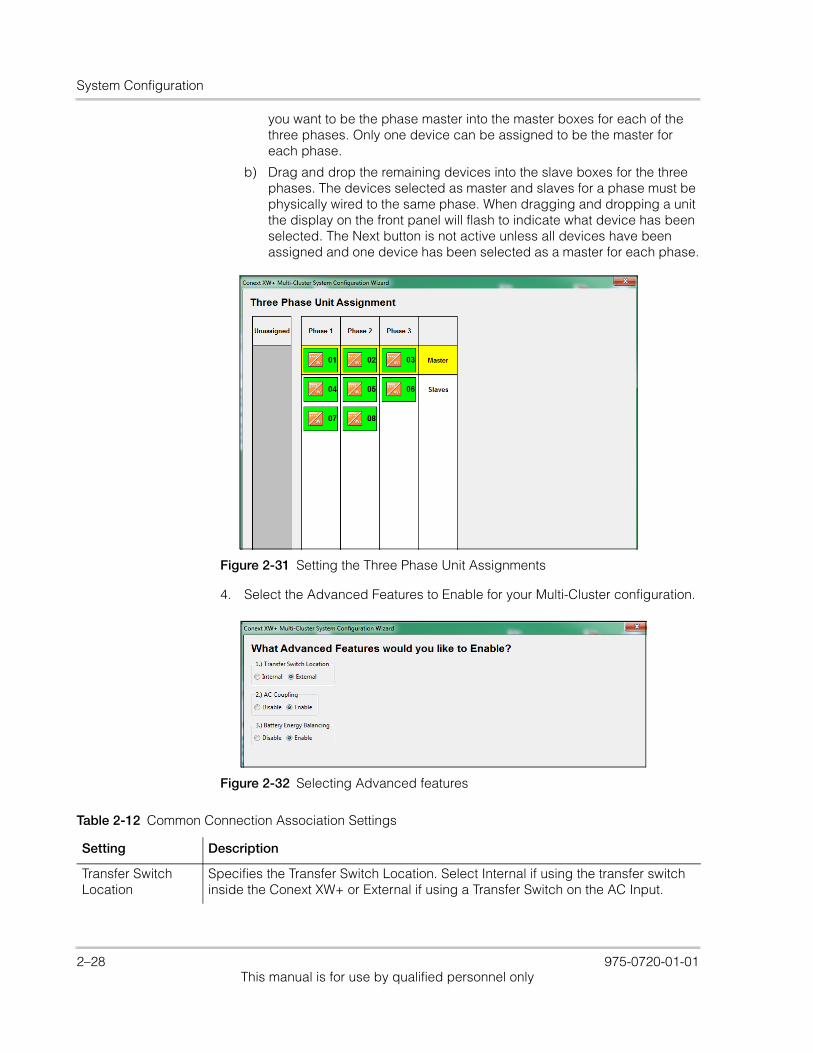
System Configuration
you want to be the phase master into the master boxes for each of the three phases. Only one device can be assigned to be the master for each phase.
b) Drag and drop the remaining devices into the slave boxes for the three phases. The devices selected as master and slaves for a phase must be physically wired to the same phase. When dragging and dropping a unit the display on the front panel will flash to indicate what device has been selected. The Next button is not active unless all devices have been assigned and one device has been selected as a master for each phase.
4. Select the Advanced Features to Enable for your Multi-Cluster configuration.
Figure 2-31 Setting the Three Phase Unit Assignments
Figure 2-32 Selecting Advanced features
Table 2-12 Common Connection Association Settings
Setting Description
Transfer Switch Location
Specifies the Transfer Switch Location. Select Internal if using the transfer switch inside the Conext XW+ or External if using a Transfer Switch on the AC Input.
2–28 975-0720-01-01This manual is for use by qualified personnel only

Using the Configuration Wizard
5. A Battery Cluster Warning will appear advising that the battery changes will apply across all clusters in the system. After taking note to adjust settings as necessary, click next.
6. Set the XW Inverter/Charger Inverter Settings as outlined in step 5 of the “Detailed Configuration Method”.
7. Set the XW + Charger Settings. Note that if Custom is selected as Battery Type, the next screen will allow you to configure custom settings.
AC Coupling This function is enabled by default and should remain enabled except in cases where the DC voltage level is allowed to have large variations and the AC line frequency needs to remain constant.
Battery Energy Balancing
This feature is intended for use with inverters drawing power from a single battery bank. The Battery Balance function should be enabled when Conext XW+ units are used in multi-cluster systems with multiple battery banks. When enabled, this feature helps balance the power draw across multiple battery banks.
Table 2-12 Common Connection Association Settings
Setting Description
Figure 2-33 Setting the XW+ Charger Settings
Setting Description
Battery Type Selects the system battery chemistry and type: Flooded (default), AGM, Gel, Custom and Lithium Ion.
If you select Custom, a screen for configuring voltage settings for each charging stage is displayed after you click Next.
Battery Capacity
Selects the system battery capacity in amp-hours.
Charger Enabled
Enables or disables the charger.
Maximum Charge Rate
Sets the percentage of the maximum DC output current that is available to the charger. Refer to the Owner’s Guide for your inverter to determine the maximum DC output current for different models.
975-0720-01-01 2–29This manual is for use by qualified personnel only

System Configuration
8. If Custom was selected as Battery Type, set the Conext XW Inverter/Charger Custom Battery Settings as detailed in Step 6 of the “Quick Configuration Method”.
9. If Lithium Ion was selected as Battery Type, set the Conext XW Inverter/Charger Lithium Ion Battery Settings.
Charge Cycle Sets the charging method: 3Stage (Bulk, Absorption, Float) and 2StageNoFloat (Bulk, Absorption, NoFloat), and CVCC.
Recharge Volts Sets the battery voltage level at which a new charge cycle begins.
Absorption Time
Sets the time spent in the Absorption stage, before transitioning to Float (3-Stage charging) or NoFloat (2-Stage charging).
Default Battery Temperature
Selects the battery temperature charging compensation if a battery temperature sensor is not installed. In the absence of a battery temperature sensor, the charger uses one of three settings: “Cool” (5 °C), “Warm” (25 °C), or “Hot” (40 °C).
Charger Block Start
Sets the time to halt charging on AC1 (Grid). The AC2 (Gen) port is unaffected by the Charger Block settings. The Charger Block Start and Stop settings allow you to select when the charger stops charging on AC1.
Charger Block Stop
Sets the time that charging on AC1 can resume. At the Chg Block Stop time, charging on AC1 is enabled again.
Setting Description
Figure 2-34 Setting the Lithium Ion Battery Settings
Setting Description
Battery Type Pre-set to Lithium Ion as selected in the previous step.
Charge Cycle Sets the charging method: 3Stage (Bulk, Absorption, Float), 2StageNoFloat (Bulk, Absorption, NoFloat), and CVCC.
Maximum Discharge Current
Specifies a percentage of battery current within which the contactor will open in case of an overload.
Maximum Discharge Time
Specifies the interval in seconds between each verification of the Maximum Discharge Current.
2–30 975-0720-01-01This manual is for use by qualified personnel only
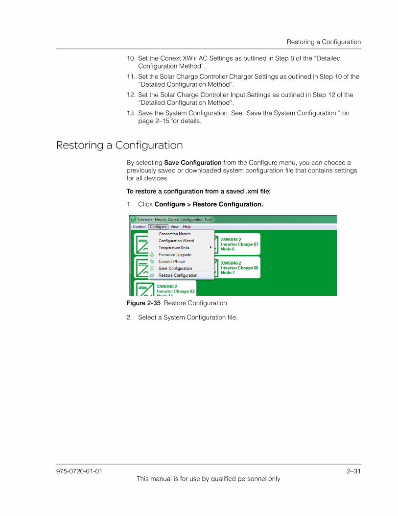
Restoring a Configuration
10. Set the Conext XW+ AC Settings as outlined in Step 8 of the “Detailed Configuration Method”.
11. Set the Solar Charge Controller Charger Settings as outlined in Step 10 of the “Detailed Configuration Method”.
12. Set the Solar Charge Controller Input Settings as outlined in Step 12 of the “Detailed Configuration Method”.
13. Save the System Configuration. See “Save the System Configuration.” on page 2–15 for details.
Restoring a Configuration
By selecting Save Configuration from the Configure menu, you can choose a previously saved or downloaded system configuration file that contains settings for all devices.
To restore a configuration from a saved .xml file:
1. Click Configure > Restore Configuration.
2. Select a System Configuration file.
Figure 2-35 Restore Configuration
975-0720-01-01 2–31This manual is for use by qualified personnel only
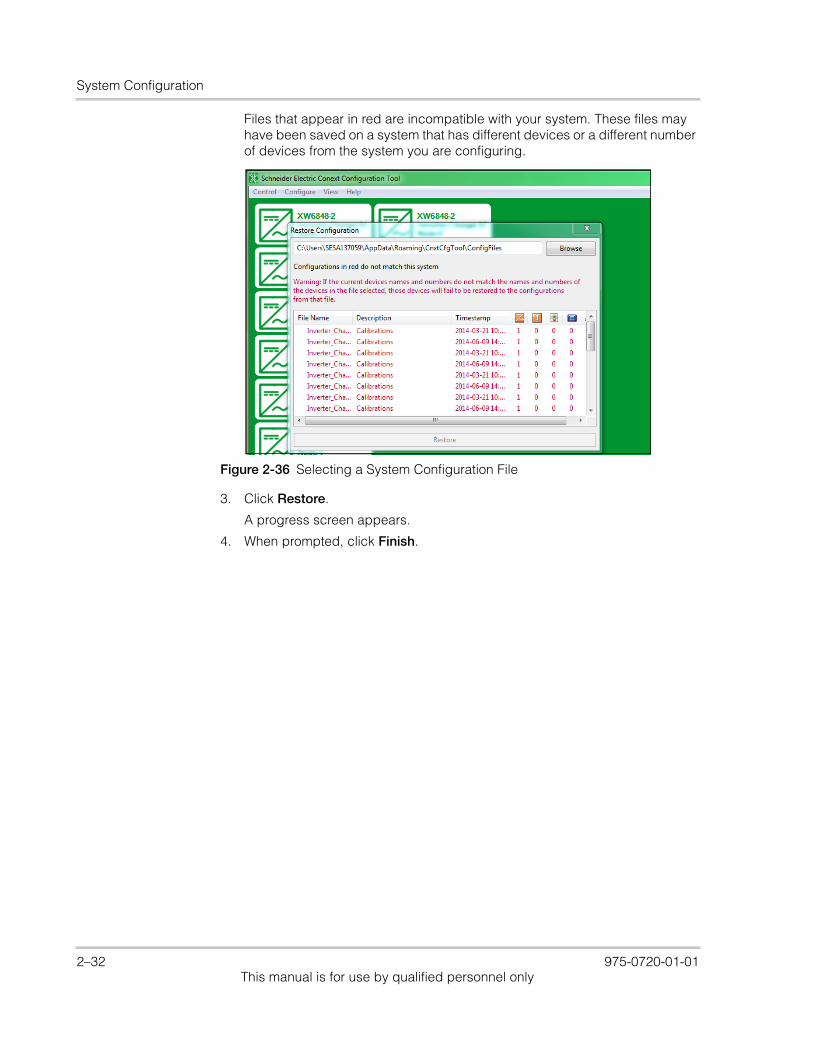
System Configuration
Files that appear in red are incompatible with your system. These files may have been saved on a system that has different devices or a different number of devices from the system you are configuring.
3. Click Restore.
A progress screen appears.
4. When prompted, click Finish.
Figure 2-36 Selecting a System Configuration File
2–32 975-0720-01-01This manual is for use by qualified personnel only
3 Device Configuration
Chapter 3, “Device Configuration” describes how to use Conext Configuration Tool to configure each device in the system.
Topics in this chapter include:• “Configuring Devices” on page 3–2• “Configuring Conext XW+ and Conext
SW Inverter/Chargers” on page 3–4• “Configuring Conext MPPT 80 600 and
Conext MPPT 60 150 Solar Charge Controllers” on page 3–21
• “Configuring the Conext Automatic Generator Start” on page 3–28
• “Configuring the System Control Panel” on page 3–34
• “Configuring the Conext Battery Monitor” on page 3–36.
975-0720-01-01 3–1This manual is for use by qualified personnel only
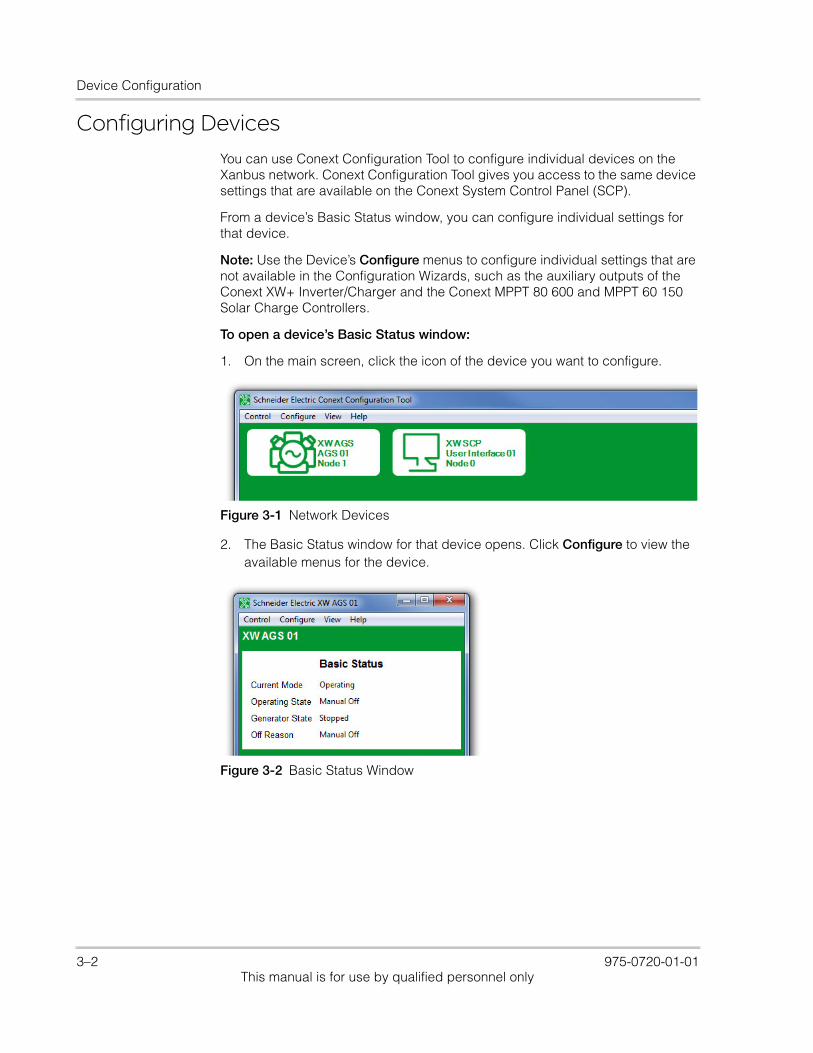
Device Configuration
Configuring DevicesYou can use Conext Configuration Tool to configure individual devices on the Xanbus network. Conext Configuration Tool gives you access to the same device settings that are available on the Conext System Control Panel (SCP).
From a device’s Basic Status window, you can configure individual settings for that device.
Note: Use the Device’s Configure menus to configure individual settings that are not available in the Configuration Wizards, such as the auxiliary outputs of the Conext XW+ Inverter/Charger and the Conext MPPT 80 600 and MPPT 60 150 Solar Charge Controllers.
To open a device’s Basic Status window:
1. On the main screen, click the icon of the device you want to configure.
2. The Basic Status window for that device opens. Click Configure to view the available menus for the device.
Figure 3-1 Network Devices
Figure 3-2 Basic Status Window
3–2 975-0720-01-01This manual is for use by qualified personnel only
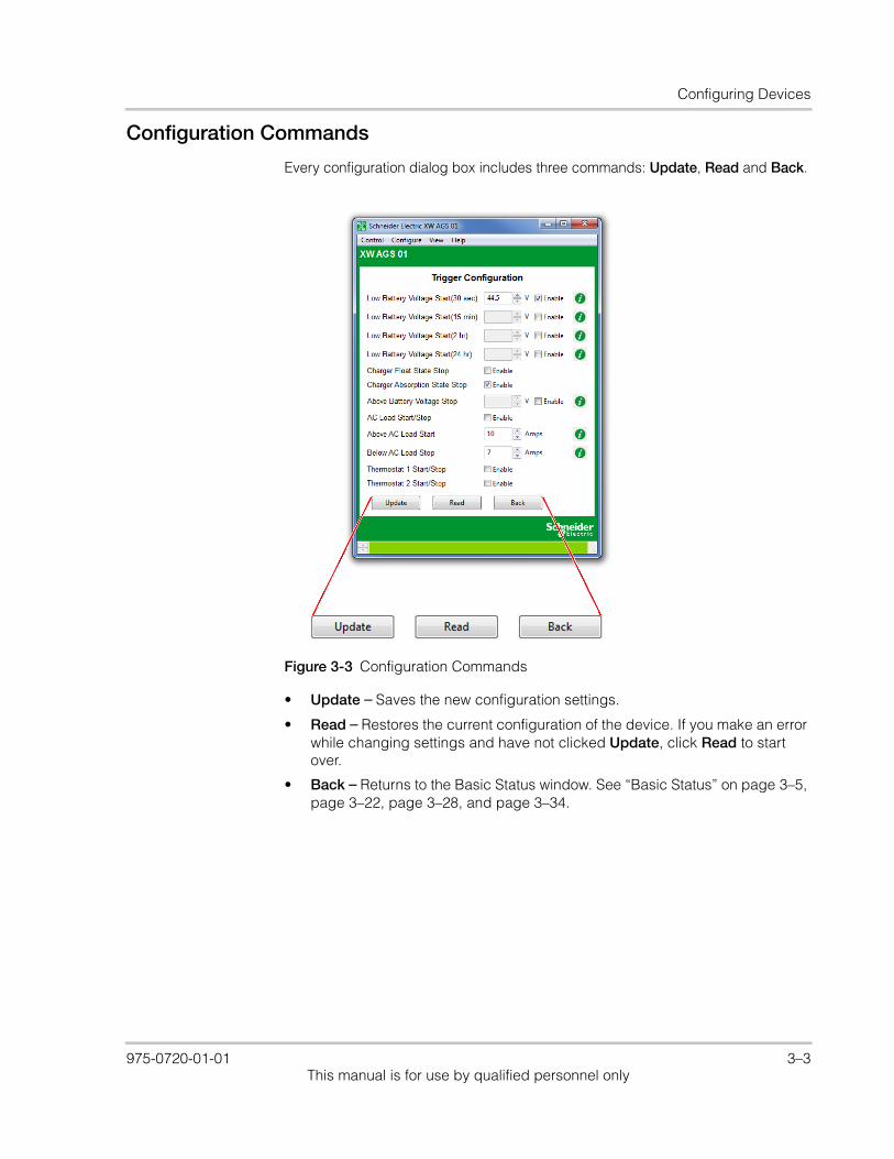
Configuring Devices
Configuration Commands
Every configuration dialog box includes three commands: Update, Read and Back.
• Update – Saves the new configuration settings.
• Read – Restores the current configuration of the device. If you make an error while changing settings and have not clicked Update, click Read to start over.
• Back – Returns to the Basic Status window. See “Basic Status” on page 3–5, page 3–22, page 3–28, and page 3–34.
Figure 3-3 Configuration Commands
975-0720-01-01 3–3This manual is for use by qualified personnel only
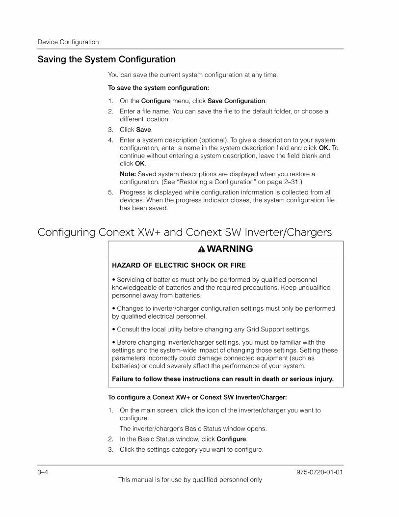
Device Configuration
Saving the System Configuration
You can save the current system configuration at any time.
To save the system configuration:
1. On the Configure menu, click Save Configuration.
2. Enter a file name. You can save the file to the default folder, or choose a different location.
3. Click Save.
4. Enter a system description (optional). To give a description to your system configuration, enter a name in the system description field and click OK. To continue without entering a system description, leave the field blank and click OK.
Note: Saved system descriptions are displayed when you restore a configuration. (See “Restoring a Configuration” on page 2–31.)
5. Progress is displayed while configuration information is collected from all devices. When the progress indicator closes, the system configuration file has been saved.
Configuring Conext XW+ and Conext SW Inverter/Chargers
To configure a Conext XW+ or Conext SW Inverter/Charger:
1. On the main screen, click the icon of the inverter/charger you want to configure.
The inverter/charger’s Basic Status window opens.
2. In the Basic Status window, click Configure.
3. Click the settings category you want to configure.
WARNING
HAZARD OF ELECTRIC SHOCK OR FIRE
• Servicing of batteries must only be performed by qualified personnel knowledgeable of batteries and the required precautions. Keep unqualified personnel away from batteries.
• Changes to inverter/charger configuration settings must only be performed by qualified electrical personnel.
• Consult the local utility before changing any Grid Support settings.
• Before changing inverter/charger settings, you must be familiar with the settings and the system-wide impact of changing those settings. Setting these parameters incorrectly could damage connected equipment (such as batteries) or could severely affect the performance of your system.
Failure to follow these instructions can result in death or serious injury.
3–4 975-0720-01-01This manual is for use by qualified personnel only

Configuring Conext XW+ and Conext SW Inverter/Chargers
The following setting categories are available on the Conext XW+ and Conext SW Inverter/Charger Configure menus:
• Inverter Configuration
• Charger Configuration
• Battery Configuration
• AC Transfer Configuration
• Generator Support Configuration
• Multi-unit Configuration
• Advanced Features
• Save Configuration
• Restore Configuration
Conext XW+ only: • Auxiliary Relay Configuration
• Grid Interactive Menu for Grid Support Configuration
Basic Status
The Basic Status window shows input and output voltage, current, and power, as well as the state of the inverter and charger. This window appears when you click on any inverter from the main screen window.
Conext XW+ only: The top-level configuration of the inverter/charger (Inverter Enable, Charger Enable, Search Mode Enable, Grid Support Enable, Sell Enable, and Peak Load Shaving Enable) is displayed in the bottom left corner.
Figure 3-4 Inverter/Charger Configure Menu
975-0720-01-01 3–5This manual is for use by qualified personnel only
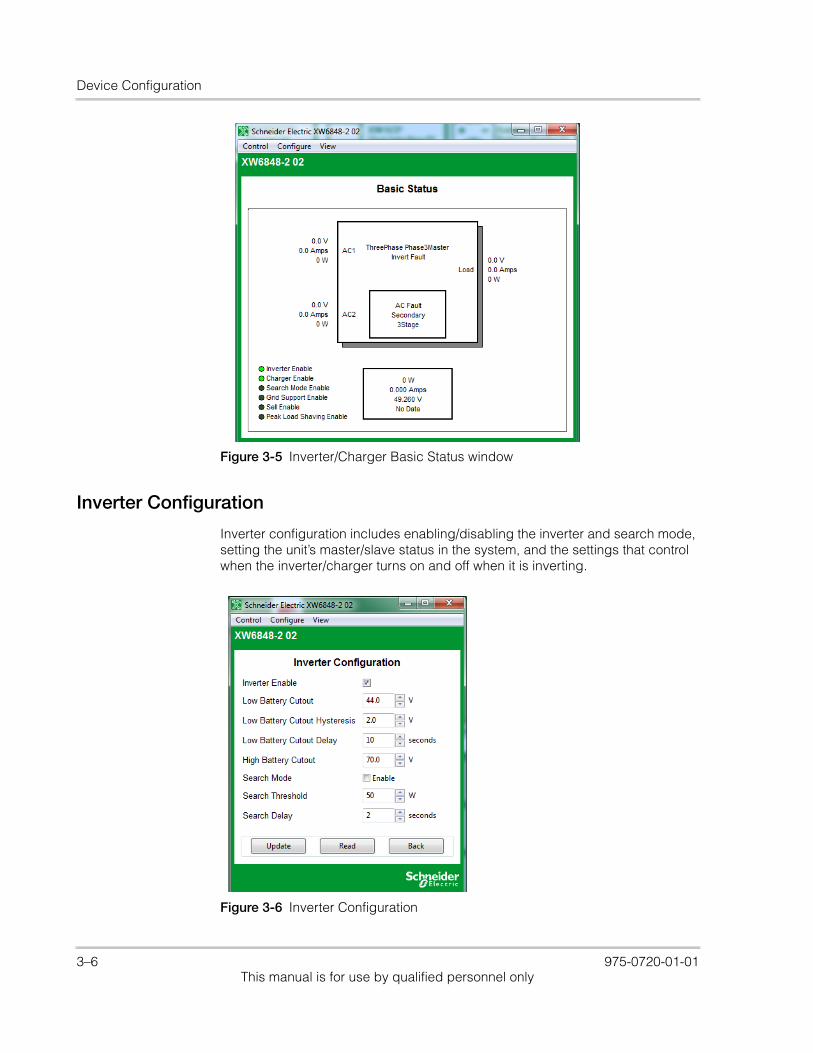
Device Configuration
Inverter Configuration
Inverter configuration includes enabling/disabling the inverter and search mode, setting the unit’s master/slave status in the system, and the settings that control when the inverter/charger turns on and off when it is inverting.
Figure 3-5 Inverter/Charger Basic Status window
Figure 3-6 Inverter Configuration
3–6 975-0720-01-01This manual is for use by qualified personnel only
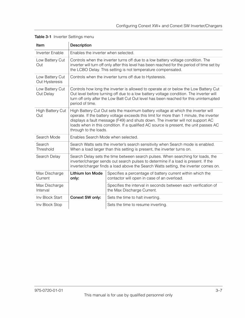
Configuring Conext XW+ and Conext SW Inverter/Chargers
Table 3-1 Inverter Settings menu
Item Description
Inverter Enable Enables the inverter when selected.
Low Battery Cut Out
Controls when the inverter turns off due to a low battery voltage condition. The inverter will turn off only after this level has been reached for the period of time set by the LCBO Delay. This setting is not temperature compensated.
Low Battery Cut Out Hysteresis
Controls when the inverter turns off due to Hysteresis.
Low Battery Cut Out Delay
Controls how long the inverter is allowed to operate at or below the Low Battery Cut Out level before turning off due to a low battery voltage condition. The inverter will turn off only after the Low Batt Cut Out level has been reached for this uninterrupted period of time.
High Battery Cut Out
High Battery Cut Out sets the maximum battery voltage at which the inverter will operate. If the battery voltage exceeds this limit for more than 1 minute, the inverter displays a fault message (F49) and shuts down. The inverter will not support AC loads when in this condition. If a qualified AC source is present, the unit passes AC through to the loads.
Search Mode Enables Search Mode when selected.
Search Threshold
Search Watts sets the inverter’s search sensitivity when Search mode is enabled. When a load larger than this setting is present, the inverter turns on.
Search Delay Search Delay sets the time between search pulses. When searching for loads, the inverter/charger sends out search pulses to determine if a load is present. If the inverter/charger finds a load above the Search Watts setting, the inverter comes on.
Max Discharge Current
Lithium Ion Mode only:
Specifies a percentage of battery current within which the contactor will open in case of an overload.
Max Discharge Interval
Specifies the interval in seconds between each verification of the Max Discharge Current.
Inv Block Start Conext SW only: Sets the time to halt inverting.
Inv Block Stop Sets the time to resume inverting.
975-0720-01-01 3–7This manual is for use by qualified personnel only
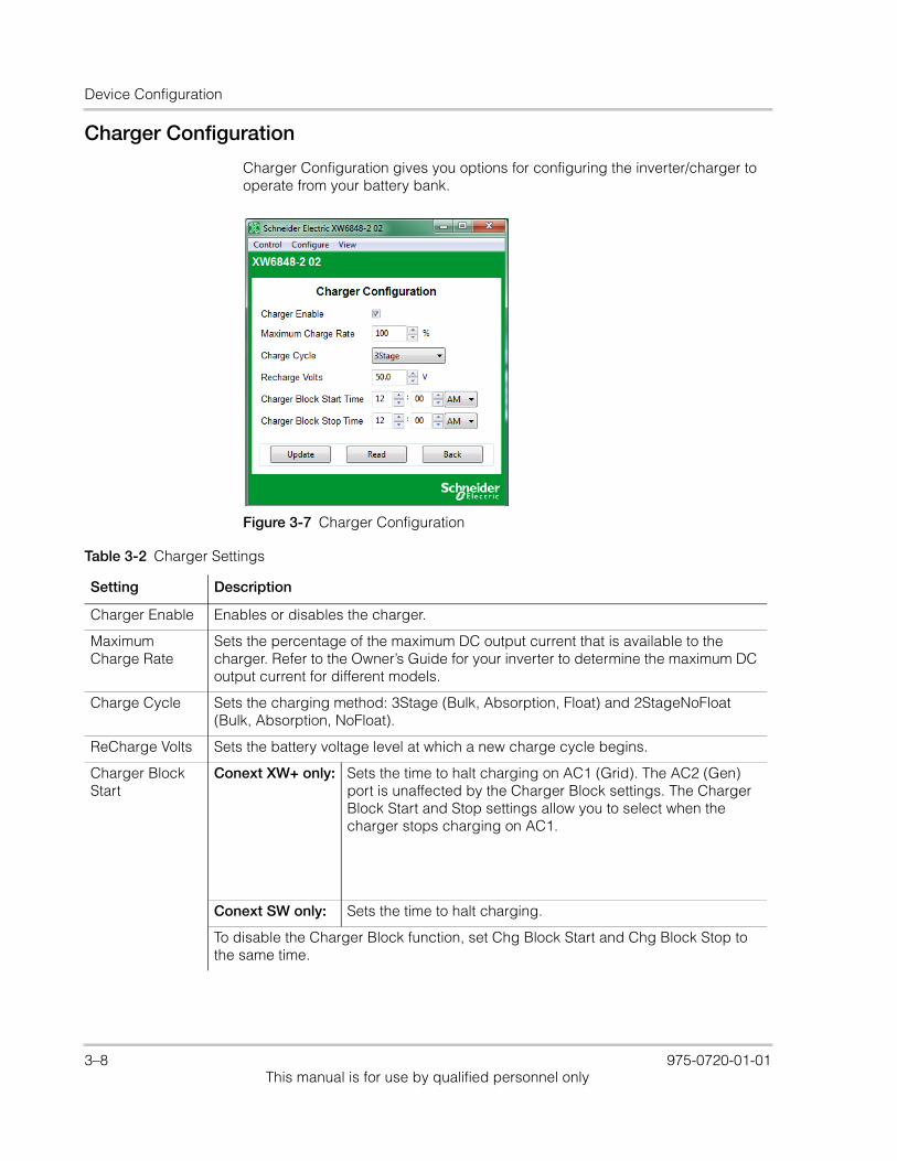
Device Configuration
Charger Configuration
Charger Configuration gives you options for configuring the inverter/charger to operate from your battery bank.
Figure 3-7 Charger Configuration
Table 3-2 Charger Settings
Setting Description
Charger Enable Enables or disables the charger.
Maximum Charge Rate
Sets the percentage of the maximum DC output current that is available to the charger. Refer to the Owner’s Guide for your inverter to determine the maximum DC output current for different models.
Charge Cycle Sets the charging method: 3Stage (Bulk, Absorption, Float) and 2StageNoFloat (Bulk, Absorption, NoFloat).
ReCharge Volts Sets the battery voltage level at which a new charge cycle begins.
Charger Block Start
Conext XW+ only: Sets the time to halt charging on AC1 (Grid). The AC2 (Gen) port is unaffected by the Charger Block settings. The Charger Block Start and Stop settings allow you to select when the charger stops charging on AC1.
Conext SW only: Sets the time to halt charging.
To disable the Charger Block function, set Chg Block Start and Chg Block Stop to the same time.
3–8 975-0720-01-01This manual is for use by qualified personnel only
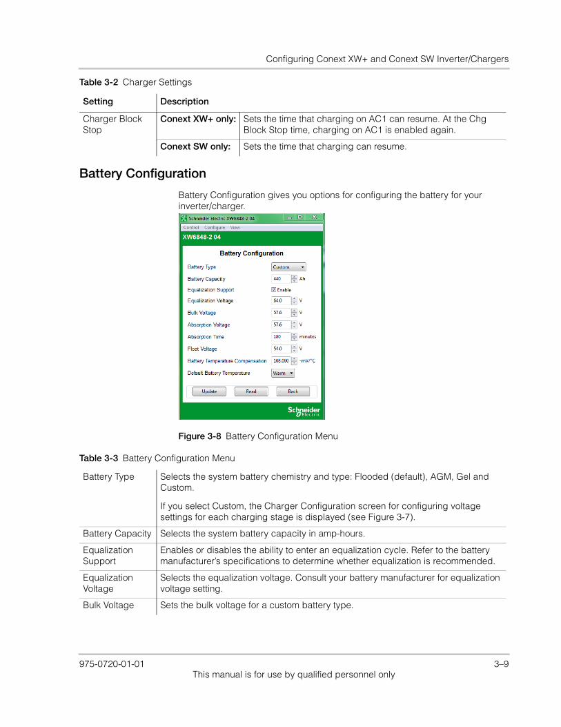
Configuring Conext XW+ and Conext SW Inverter/Chargers
Battery Configuration
Battery Configuration gives you options for configuring the battery for your inverter/charger.
Charger Block Stop
Conext XW+ only: Sets the time that charging on AC1 can resume. At the Chg Block Stop time, charging on AC1 is enabled again.
Conext SW only: Sets the time that charging can resume.
Table 3-2 Charger Settings
Setting Description
Figure 3-8 Battery Configuration Menu
Table 3-3 Battery Configuration Menu
Battery Type Selects the system battery chemistry and type: Flooded (default), AGM, Gel and Custom.
If you select Custom, the Charger Configuration screen for configuring voltage settings for each charging stage is displayed (see Figure 3-7).
Battery Capacity Selects the system battery capacity in amp-hours.
Equalization Support
Enables or disables the ability to enter an equalization cycle. Refer to the battery manufacturer’s specifications to determine whether equalization is recommended.
Equalization Voltage
Selects the equalization voltage. Consult your battery manufacturer for equalization voltage setting.
Bulk Voltage Sets the bulk voltage for a custom battery type.
975-0720-01-01 3–9This manual is for use by qualified personnel only
Device Configuration
AC Transfer Configuration
AC Transfer configures the voltage and frequency limits for AC line 1 (grid) and AC line 2 (generator). These are the limits at which the inverter/charger considers input voltage qualified—that is, suitable for charging batteries or powering loads. If the input voltage is not qualified according to these settings, the inverter/charger transfers from using AC input to inverting.
Absorption Voltage
Sets the absorption voltage for a custom battery type.
Absorption Time Sets the time spent in the Absorption stage, before transitioning to Float (3-Stage charging) or NoFloat (2-Stage charging).
Float Voltage Sets the float voltage for a custom battery type.
Battery Temperature Compensation
Battery temperature compensation for a custom battery type. This setting is the reference that the battery temperature sensor uses to adjust the charging voltage when the temperature falls above or below 25 °C.
Default Battery Temperature
Selects the battery temperature charging compensation if a battery temperature sensor is not installed. In the absence of a battery temperature sensor, the charger uses one of three settings: “Cool” (5 °C), “Warm” (25 °C), or “Hot” (40 °C).
Table 3-3 Battery Configuration Menu
3–10 975-0720-01-01This manual is for use by qualified personnel only
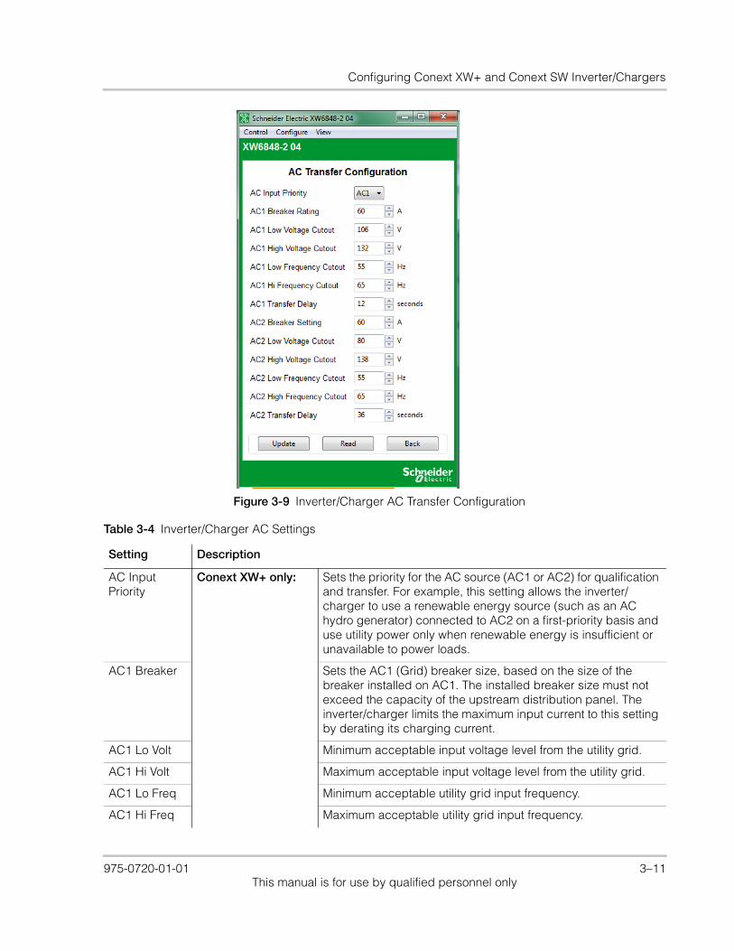
Configuring Conext XW+ and Conext SW Inverter/Chargers
Figure 3-9 Inverter/Charger AC Transfer Configuration
Table 3-4 Inverter/Charger AC Settings
Setting Description
AC Input Priority
Conext XW+ only: Sets the priority for the AC source (AC1 or AC2) for qualification and transfer. For example, this setting allows the inverter/charger to use a renewable energy source (such as an AC hydro generator) connected to AC2 on a first-priority basis and use utility power only when renewable energy is insufficient or unavailable to power loads.
AC1 Breaker Sets the AC1 (Grid) breaker size, based on the size of the breaker installed on AC1. The installed breaker size must not exceed the capacity of the upstream distribution panel. The inverter/charger limits the maximum input current to this setting by derating its charging current.
AC1 Lo Volt Minimum acceptable input voltage level from the utility grid.
AC1 Hi Volt Maximum acceptable input voltage level from the utility grid.
AC1 Lo Freq Minimum acceptable utility grid input frequency.
AC1 Hi Freq Maximum acceptable utility grid input frequency.
975-0720-01-01 3–11This manual is for use by qualified personnel only
Device Configuration
Grid Tie Configuration
The Grid Tie Configuration window sets options for grid tie operation.
AC2 Breaker Conext XW+ only: Sets the AC2 (Gen) breaker size, based on the size of the installed AC breaker. The breaker size must not exceed the capacity of the generator. Conext Configuration Tool limits the maximum input current to this setting by derating its charging current.
AC2 Lo Volt Minimum acceptable input voltage level from the generator.
AC2 Hi Volt Maximum acceptable input voltage level from the generator.
AC2 Lo Freq Minimum acceptable generator input frequency.
AC2 Hi Freq Maximum acceptable generator input frequency.
XW to Gen transfer delay time
Sets the time it takes for the Conext XW+ Inverter/Charger to qualify the Gen (AC2) input.
AC Breaker Conext SW only: Sets the AC1 (Grid) breaker size, based on the size of the breaker installed on AC1. The installed breaker size must not exceed the capacity of the upstream distribution panel. The inverter/charger limits the maximum input current to this setting by derating its charging current.
AC Lo Volt Minimum acceptable input voltage level from the utility grid.
AC Hi Volt Maximum acceptable input voltage level from the utility grid.
AC Lo Freq Minimum acceptable utility grid input frequency.
AC Hi Freq Maximum acceptable utility grid input frequency.
AC Qualify Time
Sets the waiting time in seconds before the charger begins charging. Charging cannot begin until there is qualified AC (ACGood) so, the charger counts from the moment AC is qualified up to the time set in AC Qualify Time before starting to charge.
Table 3-4 Inverter/Charger AC Settings
Setting Description
3–12 975-0720-01-01This manual is for use by qualified personnel only

Configuring Conext XW+ and Conext SW Inverter/Chargers
Figure 3-10 Inverter/Charger Grid Tie Configuration
Table 3-5 Inverter/Charger Grid Support Settings
Setting Description
Grid Voltage Support Enabled
Enables Grid Support when selected.
Grid Support Voltage
Sets the level to which the batteries will be discharged when the inverter is selling power to the grid or supporting the power grid by providing additional power to the loads. This setting is not adjusted for the battery temperature if the temperature sensor is installed.
Sell Enables Sell mode when selected. Grid Support must also be enabled for Sell to be enabled. When Sell is enabled, the inverter AC output is divided between powering loads and delivering power to the utility grid. Sell mode requires the battery voltage to be above the Grid Supp Volts.
Max Sell Amps Sets the maximum AC amps allowed to be delivered to the utility grid from a solar array and/or the batteries during grid-tie operation. This setting is only used if Sell mode is enabled.
The Max Sell Amps must be less than 80 per cent of the selected AC1 breaker setting. If set higher, the breaker setting will override the Max Sell Amps setting to avoid tripping the breaker. Sell can be limited with both this function and with Max Sell Power Scale Percent.
975-0720-01-01 3–13This manual is for use by qualified personnel only

Device Configuration
Generator Support Configuration
Conext XW+ only: Generator support allows power to be automatically drawn from the batteries to assist an AC generator to support heavy loads (i.e. loads that exceed the available current from the generator).
Max Sell Power Scale Percent
Sets the sell active power percentage. The max sell power scale is 100% by default. Sell can be limited with both this function and with Max Sell Amps.
Sell Block Start Specifies the start time after which the grid sell feature will be Blocked (deactivated).
Sell Block Stop Specifies the stop time before which the grid sell feature will be Blocked (deactivated).
Load Shave Enables or disables the Load Shave feature. Grid Support must also be enabled for Load Shave to be enabled. Load Shave allows the inverter to support the grid in powering local loads during a defined window of time (set using Load Shave Start and Load Shave Stop). When in this mode, the inverter operates until the batteries discharge to the LBCO threshold, after which the unit reverts to AC pass-through. The charger is automatically blocked during the Load Shave time window.
Load Shave Amps
Sets the maximum amount of current that can be drawn from the AC1 (grid) input by the loads and battery charger combined. This setting determines the amperage level at which the inverter starts drawing power from the batteries to add to the utility power to meet the demand of the loads.
Typically, this value is set to the size of the AC circuit breakers feeding the inverter’s AC input.
Load Shave Start
Sets the time of day that the Load Shave feature operates. This feature is suited for regions where local utilities impose peak usage surcharges. The inverter provides load shaving power as long as battery voltage is above the Low Batt Cut Out setting.
Load Shave Stop
Sets the time of day that the Load Shave feature stops operating. If Load Shave is enabled and Load Shave Start and Load Shave Stop are set to the same time, the inverter load shaves continuously.
Table 3-5 Inverter/Charger Grid Support Settings
Setting Description
3–14 975-0720-01-01This manual is for use by qualified personnel only
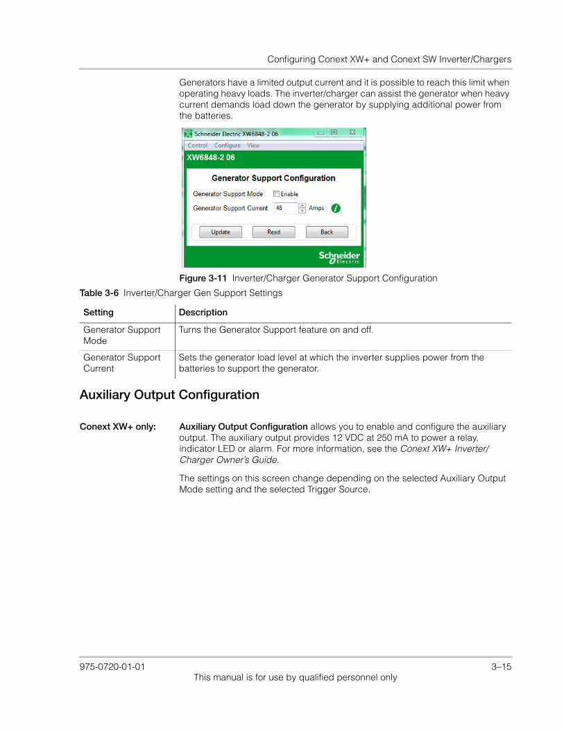
Configuring Conext XW+ and Conext SW Inverter/Chargers
Generators have a limited output current and it is possible to reach this limit when operating heavy loads. The inverter/charger can assist the generator when heavy current demands load down the generator by supplying additional power from the batteries.
Auxiliary Output Configuration
Conext XW+ only: Auxiliary Output Configuration allows you to enable and configure the auxiliary output. The auxiliary output provides 12 VDC at 250 mA to power a relay, indicator LED or alarm. For more information, see the Conext XW+ Inverter/Charger Owner’s Guide.
The settings on this screen change depending on the selected Auxiliary Output Mode setting and the selected Trigger Source.
Figure 3-11 Inverter/Charger Generator Support Configuration
Table 3-6 Inverter/Charger Gen Support Settings
Setting Description
Generator Support Mode
Turns the Generator Support feature on and off.
Generator Support Current
Sets the generator load level at which the inverter supplies power from the batteries to support the generator.
975-0720-01-01 3–15This manual is for use by qualified personnel only
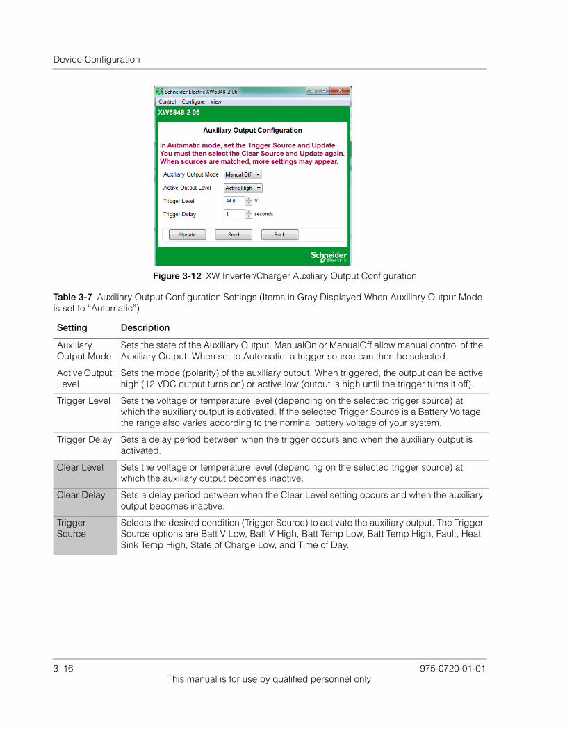
Device Configuration
Figure 3-12 XW Inverter/Charger Auxiliary Output Configuration
Table 3-7 Auxiliary Output Configuration Settings (Items in Gray Displayed When Auxiliary Output Mode is set to “Automatic”)
Setting Description
Auxiliary Output Mode
Sets the state of the Auxiliary Output. ManualOn or ManualOff allow manual control of the Auxiliary Output. When set to Automatic, a trigger source can then be selected.
Active Output Level
Sets the mode (polarity) of the auxiliary output. When triggered, the output can be active high (12 VDC output turns on) or active low (output is high until the trigger turns it off).
Trigger Level Sets the voltage or temperature level (depending on the selected trigger source) at which the auxiliary output is activated. If the selected Trigger Source is a Battery Voltage, the range also varies according to the nominal battery voltage of your system.
Trigger Delay Sets a delay period between when the trigger occurs and when the auxiliary output is activated.
Clear Level Sets the voltage or temperature level (depending on the selected trigger source) at which the auxiliary output becomes inactive.
Clear Delay Sets a delay period between when the Clear Level setting occurs and when the auxiliary output becomes inactive.
Trigger Source
Selects the desired condition (Trigger Source) to activate the auxiliary output. The Trigger Source options are Batt V Low, Batt V High, Batt Temp Low, Batt Temp High, Fault, Heat Sink Temp High, State of Charge Low, and Time of Day.
3–16 975-0720-01-01This manual is for use by qualified personnel only

Configuring Conext XW+ and Conext SW Inverter/Chargers
Figure 3-13 XW Inverter/Charger Auxiliary Output Configuration (Batt Temp Triggers)
Figure 3-14 XW Inverter/Charger Auxiliary Output Configuration (Batt Voltage Triggers)
975-0720-01-01 3–17This manual is for use by qualified personnel only
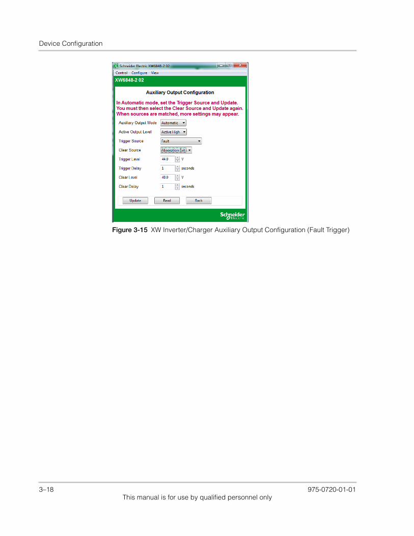
Device Configuration
Figure 3-15 XW Inverter/Charger Auxiliary Output Configuration (Fault Trigger)
3–18 975-0720-01-01This manual is for use by qualified personnel only
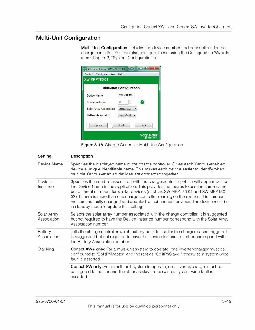
Configuring Conext XW+ and Conext SW Inverter/Chargers
Multi-Unit Configuration
Multi-Unit Configuration includes the device number and connections for the charge controller. You can also configure these using the Configuration Wizards (see Chapter 2, “System Configuration”).
Figure 3-16 Charge Controller Multi-Unit Configuration
Setting Description
Device Name Specifies the displayed name of the charge controller. Gives each Xanbus-enabled device a unique identifiable name. This makes each device easier to identify when multiple Xanbus-enabled devices are connected together.
Device Instance
Specifies the number associated with the charge controller, which will appear beside the Device Name in the application. This provides the means to use the same name, but different numbers for similar devices (such as XW MPPT80 01 and XW MPPT80 02). If there is more than one charge controller running on the system, this number must be manually changed and updated for subsequent devices. The device must be in standby mode to update this setting.
Solar Array Association
Selects the solar array number associated with the charge controller. It is suggested but not required to have the Device Instance number correspond with the Solar Array Association number.
Battery Association
Tells the charge controller which battery bank to use for the charger based triggers. It is suggested but not required to have the Device Instance number correspond with the Battery Association number.
Stacking Conext XW+ only: For a multi-unit system to operate, one inverter/charger must be configured to “SplitPhMaster” and the rest as “SplitPhSlave,” otherwise a system-wide fault is asserted.
Conext SW only: For a multi-unit system to operate, one inverter/charger must be configured to master and the other as slave, otherwise a system-wide fault is asserted.
975-0720-01-01 3–19This manual is for use by qualified personnel only
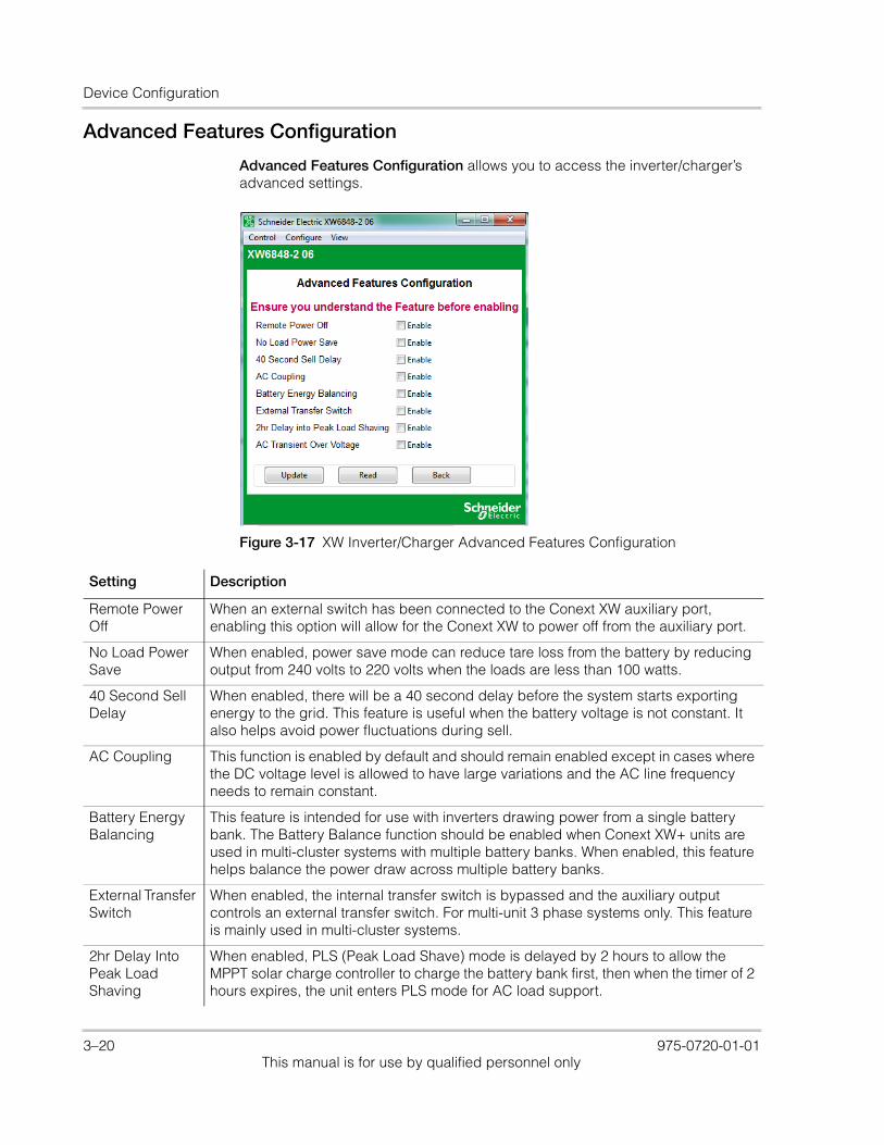
Device Configuration
Advanced Features Configuration
Advanced Features Configuration allows you to access the inverter/charger’s advanced settings.
Figure 3-17 XW Inverter/Charger Advanced Features Configuration
Setting Description
Remote Power Off
When an external switch has been connected to the Conext XW auxiliary port, enabling this option will allow for the Conext XW to power off from the auxiliary port.
No Load Power Save
When enabled, power save mode can reduce tare loss from the battery by reducing output from 240 volts to 220 volts when the loads are less than 100 watts.
40 Second Sell Delay
When enabled, there will be a 40 second delay before the system starts exporting energy to the grid. This feature is useful when the battery voltage is not constant. It also helps avoid power fluctuations during sell.
AC Coupling This function is enabled by default and should remain enabled except in cases where the DC voltage level is allowed to have large variations and the AC line frequency needs to remain constant.
Battery Energy Balancing
This feature is intended for use with inverters drawing power from a single battery bank. The Battery Balance function should be enabled when Conext XW+ units are used in multi-cluster systems with multiple battery banks. When enabled, this feature helps balance the power draw across multiple battery banks.
External Transfer Switch
When enabled, the internal transfer switch is bypassed and the auxiliary output controls an external transfer switch. For multi-unit 3 phase systems only. This feature is mainly used in multi-cluster systems.
2hr Delay Into Peak Load Shaving
When enabled, PLS (Peak Load Shave) mode is delayed by 2 hours to allow the MPPT solar charge controller to charge the battery bank first, then when the timer of 2 hours expires, the unit enters PLS mode for AC load support.
3–20 975-0720-01-01This manual is for use by qualified personnel only
Configuring Conext MPPT 80 600 and Conext MPPT 60 150 Solar Charge Controllers
Saving and Restoring Configurations
Save Configuration allows you to save the current configuration of the inverter/charger. Restore Configuration allows you to restore a previously saved configuration from a file. See “Restoring a Configuration” on page 2–31 for further details.
Configuring Conext MPPT 80 600 and Conext MPPT 60 150 Solar Charge Controllers
The following section describes how to configure Conext MPPT 80 600 and Conext MPPT 60 150 Solar Charge Controllers.
To configure a Conext MPPT 80 600 or Conext MPPT 60 150 Solar Charge Controller:
1. On the main screen, click the icon of the charge controller you want to configure.
The charge controller’s Basic Status window opens.
2. In the Basic Status window, click Configure.
3. Click the settings category you want to configure.
The following settings categories are available on the Configure menu of the MPPT 80 600 and MPPT 60 150 Solar Charge Controllers:
• Multi-Unit Configuration
• Charger Configuration
• Battery Configuration
• Solar Input Configuration
• Auxiliary Output Configuration
• Save Configuration
• Restore Configuration
MPPT 80 600 only: • Advanced Features
AC Transient Over Voltage
When enabled, the inverter will stop exporting power to the grid when the grid voltage exceeds 120% of nominal (as per HECO Standard).
GenSupp Plus Only enabled on a split-phase Conext XW. When enabled, this feature helps to balance the generator input L1 and L2 phases under severe imbalanced loads on L1 and L2. This should only be enabled for generators below 5 kW.
Setting Description
975-0720-01-01 3–21This manual is for use by qualified personnel only
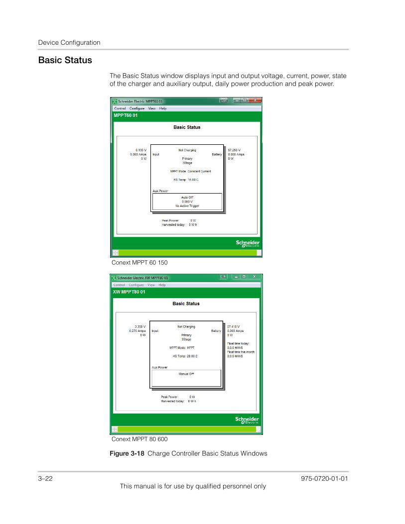
Device Configuration
Basic Status
The Basic Status window displays input and output voltage, current, power, state of the charger and auxiliary output, daily power production and peak power.
Figure 3-18 Charge Controller Basic Status Windows
Conext MPPT 60 150
Conext MPPT 80 600
3–22 975-0720-01-01This manual is for use by qualified personnel only
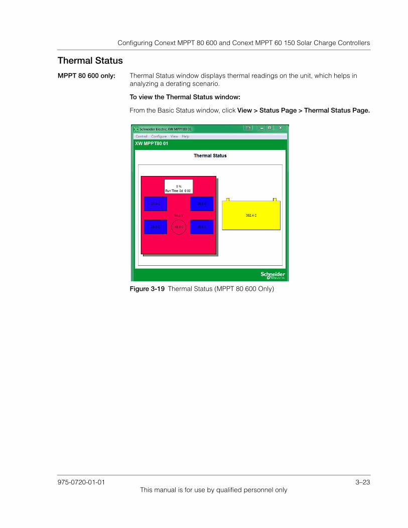
Configuring Conext MPPT 80 600 and Conext MPPT 60 150 Solar Charge Controllers
Thermal Status
MPPT 80 600 only: Thermal Status window displays thermal readings on the unit, which helps in analyzing a derating scenario.
To view the Thermal Status window:
From the Basic Status window, click View > Status Page > Thermal Status Page.
Figure 3-19 Thermal Status (MPPT 80 600 Only)
975-0720-01-01 3–23This manual is for use by qualified personnel only
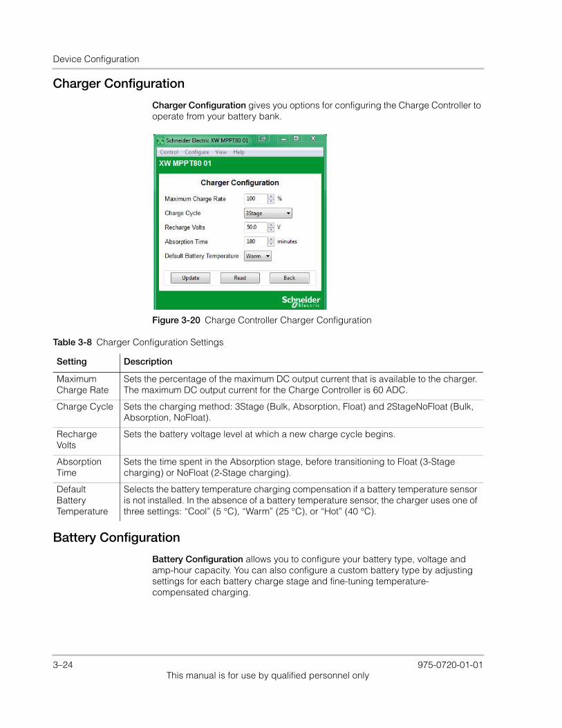
Device Configuration
Charger Configuration
Charger Configuration gives you options for configuring the Charge Controller to operate from your battery bank.
Battery Configuration
Battery Configuration allows you to configure your battery type, voltage and amp-hour capacity. You can also configure a custom battery type by adjusting settings for each battery charge stage and fine-tuning temperature-compensated charging.
Figure 3-20 Charge Controller Charger Configuration
Table 3-8 Charger Configuration Settings
Setting Description
Maximum Charge Rate
Sets the percentage of the maximum DC output current that is available to the charger. The maximum DC output current for the Charge Controller is 60 ADC.
Charge Cycle Sets the charging method: 3Stage (Bulk, Absorption, Float) and 2StageNoFloat (Bulk, Absorption, NoFloat).
Recharge Volts
Sets the battery voltage level at which a new charge cycle begins.
Absorption Time
Sets the time spent in the Absorption stage, before transitioning to Float (3-Stage charging) or NoFloat (2-Stage charging).
Default Battery Temperature
Selects the battery temperature charging compensation if a battery temperature sensor is not installed. In the absence of a battery temperature sensor, the charger uses one of three settings: “Cool” (5 °C), “Warm” (25 °C), or “Hot” (40 °C).
3–24 975-0720-01-01This manual is for use by qualified personnel only
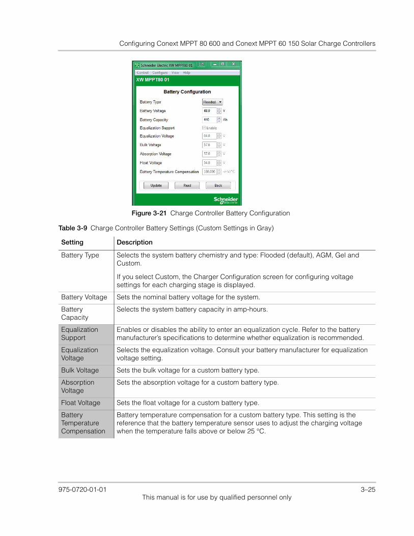
Configuring Conext MPPT 80 600 and Conext MPPT 60 150 Solar Charge Controllers
Figure 3-21 Charge Controller Battery Configuration
Table 3-9 Charge Controller Battery Settings (Custom Settings in Gray)
Setting Description
Battery Type Selects the system battery chemistry and type: Flooded (default), AGM, Gel and Custom.
If you select Custom, the Charger Configuration screen for configuring voltage settings for each charging stage is displayed.
Battery Voltage Sets the nominal battery voltage for the system.
Battery Capacity
Selects the system battery capacity in amp-hours.
Equalization Support
Enables or disables the ability to enter an equalization cycle. Refer to the battery manufacturer’s specifications to determine whether equalization is recommended.
Equalization Voltage
Selects the equalization voltage. Consult your battery manufacturer for equalization voltage setting.
Bulk Voltage Sets the bulk voltage for a custom battery type.
Absorption Voltage
Sets the absorption voltage for a custom battery type.
Float Voltage Sets the float voltage for a custom battery type.
Battery Temperature Compensation
Battery temperature compensation for a custom battery type. This setting is the reference that the battery temperature sensor uses to adjust the charging voltage when the temperature falls above or below 25 °C.
975-0720-01-01 3–25This manual is for use by qualified personnel only
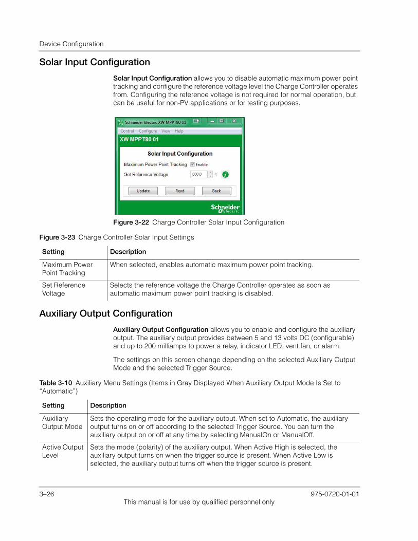
Device Configuration
Solar Input Configuration
Solar Input Configuration allows you to disable automatic maximum power point tracking and configure the reference voltage level the Charge Controller operates from. Configuring the reference voltage is not required for normal operation, but can be useful for non-PV applications or for testing purposes.
Auxiliary Output Configuration
Auxiliary Output Configuration allows you to enable and configure the auxiliary output. The auxiliary output provides between 5 and 13 volts DC (configurable) and up to 200 milliamps to power a relay, indicator LED, vent fan, or alarm.
The settings on this screen change depending on the selected Auxiliary Output Mode and the selected Trigger Source.
Figure 3-22 Charge Controller Solar Input Configuration
Figure 3-23 Charge Controller Solar Input Settings
Setting Description
Maximum Power Point Tracking
When selected, enables automatic maximum power point tracking.
Set Reference Voltage
Selects the reference voltage the Charge Controller operates as soon as automatic maximum power point tracking is disabled.
Table 3-10 Auxiliary Menu Settings (Items in Gray Displayed When Auxiliary Output Mode Is Set to “Automatic”)
Setting Description
Auxiliary Output Mode
Sets the operating mode for the auxiliary output. When set to Automatic, the auxiliary output turns on or off according to the selected Trigger Source. You can turn the auxiliary output on or off at any time by selecting ManualOn or ManualOff.
Active Output Level
Sets the mode (polarity) of the auxiliary output. When Active High is selected, the auxiliary output turns on when the trigger source is present. When Active Low is selected, the auxiliary output turns off when the trigger source is present.
3–26 975-0720-01-01This manual is for use by qualified personnel only
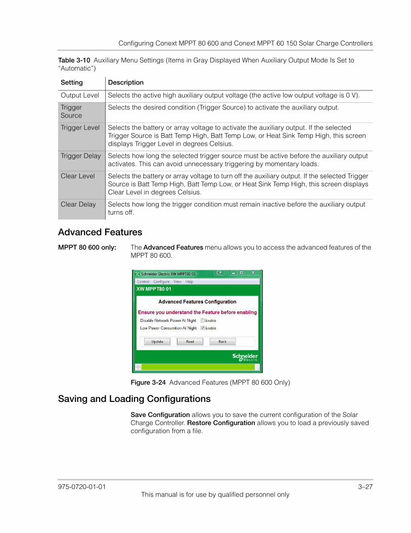
Configuring Conext MPPT 80 600 and Conext MPPT 60 150 Solar Charge Controllers
Advanced Features
MPPT 80 600 only: The Advanced Features menu allows you to access the advanced features of the MPPT 80 600.
Saving and Loading Configurations
Save Configuration allows you to save the current configuration of the Solar Charge Controller. Restore Configuration allows you to load a previously saved configuration from a file.
Output Level Selects the active high auxiliary output voltage (the active low output voltage is 0 V).
Trigger Source
Selects the desired condition (Trigger Source) to activate the auxiliary output.
Trigger Level Selects the battery or array voltage to activate the auxiliary output. If the selected Trigger Source is Batt Temp High, Batt Temp Low, or Heat Sink Temp High, this screen displays Trigger Level in degrees Celsius.
Trigger Delay Selects how long the selected trigger source must be active before the auxiliary output activates. This can avoid unnecessary triggering by momentary loads.
Clear Level Selects the battery or array voltage to turn off the auxiliary output. If the selected Trigger Source is Batt Temp High, Batt Temp Low, or Heat Sink Temp High, this screen displays Clear Level in degrees Celsius.
Clear Delay Selects how long the trigger condition must remain inactive before the auxiliary output turns off.
Table 3-10 Auxiliary Menu Settings (Items in Gray Displayed When Auxiliary Output Mode Is Set to “Automatic”)
Setting Description
Figure 3-24 Advanced Features (MPPT 80 600 Only)
975-0720-01-01 3–27This manual is for use by qualified personnel only
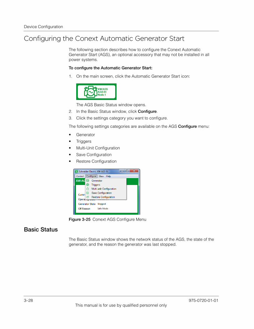
Device Configuration
Configuring the Conext Automatic Generator StartThe following section describes how to configure the Conext Automatic Generator Start (AGS), an optional accessory that may not be installed in all power systems.
To configure the Automatic Generator Start:
1. On the main screen, click the Automatic Generator Start icon:
The AGS Basic Status window opens.
2. In the Basic Status window, click Configure.
3. Click the settings category you want to configure.
The following settings categories are available on the AGS Configure menu:
• Generator
• Triggers
• Multi-Unit Configuration
• Save Configuration
• Restore Configuration
Basic Status
The Basic Status window shows the network status of the AGS, the state of the generator, and the reason the generator was last stopped.
Figure 3-25 Conext AGS Configure Menu
3–28 975-0720-01-01This manual is for use by qualified personnel only
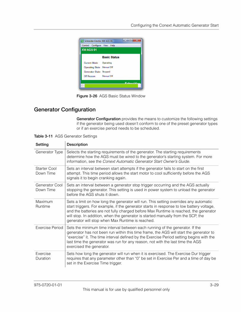
Configuring the Conext Automatic Generator Start
Generator Configuration
Generator Configuration provides the means to customize the following settings if the generator being used doesn’t conform to one of the preset generator types or if an exercise period needs to be scheduled.
Figure 3-26 AGS Basic Status Window
Table 3-11 AGS Generator Settings
Setting Description
Generator Type Selects the starting requirements of the generator. The starting requirements determine how the AGS must be wired to the generator’s starting system. For more information, see the Conext Automatic Generator Start Owner’s Guide.
Starter Cool Down Time
Sets an interval between start attempts if the generator fails to start on the first attempt. This time period allows the start motor to cool sufficiently before the AGS signals it to begin cranking again.
Generator Cool Down Time
Sets an interval between a generator stop trigger occurring and the AGS actually stopping the generator. This setting is used in power system to unload the generator before the AGS shuts it down.
Maximum Runtime
Sets a limit on how long the generator will run. This setting overrides any automatic start triggers. For example, if the generator starts in response to low battery voltage, and the batteries are not fully charged before Max Runtime is reached, the generator will stop. In addition, when the generator is started manually from the SCP, the generator will stop when Max Runtime is reached.
Exercise Period Sets the minimum time interval between each running of the generator. If the generator has not been run within this time frame, the AGS will start the generator to “exercise” it. The time interval defined by the Exercise Period setting begins with the last time the generator was run for any reason, not with the last time the AGS exercised the generator.
Exercise Duration
Sets how long the generator will run when it is exercised. The Exercise Dur trigger requires that any parameter other than “0” be set in Exercise Per and a time of day be set in the Exercise Time trigger.
975-0720-01-01 3–29This manual is for use by qualified personnel only
Device Configuration
Exercise Time Sets the time of day that the AGS exercises the generator. Exercise Time requires that any parameter other than “0” be set in Exercise Period and a value be set in Exercise Duration.
Relay 3 Function
Sets the function of Relay 3 of the AGS. The function of Relay 3 affects contacts 19 and 20 of the 20-contact connector and external wiring harness. It might be necessary to manually set Relay 3 according to the make and type of generator being used. Some diesel generators require preheating of their glow plugs before start cranking. Setting Relay 3 to Preheat enables Relay 3 to perform this function in addition to Relay 1.
Generator Run Hold Time
Specifies the length of time the generator run signal (or B+ or hour meter signal) must be active before the AGS considers the generator to be running and cranking can be stopped.
Crank Delay Time
Specifies the delay time from when the preheat relay is deenergized to when the Start Relay is energized (and cranking the starter motor).
Crank Time Specifies the maximum length of time the Start relay is engaged (and cranking the starter motor) for the first attempt to start the generator.
Crank Retry Time
Specifies the length of time the Start relay is engaged (and cranking the starter motor) for the second and subsequent attempts to start the generator, in cases when the generator fails to start on the first attempt.
Preheat Time Specifies how long the Preheat relay is engaged during the start sequence. The preheat signal may be required for diesel generators with glow plugs or fuel priming for gas generators.
Generator Start Attempts
Specifies how many times the AGS attempts to start the generator. This setting is automatically configured when a Gen Type is selected for the generator. Manually change this setting only on the advice of the generator manufacturer or authorized service personnel.
Generator Spin Down Time
Specifies an interval to be set between a generator stop signal being sent at the end of a Gen Cool Down cycle and the AGS changing the Generator State to “stopped.” This setting is automatically configured when a “Gen Type” is selected for the generator.
Quiet Time Enables/Disables Quiet Time (a period of time during when the generator should not run).
Quiet Time Begin
Specifies when Quiet Time begins.
Quiet Time End Specifies when Quiet Time ends.
Table 3-11 AGS Generator Settings
Setting Description
3–30 975-0720-01-01This manual is for use by qualified personnel only
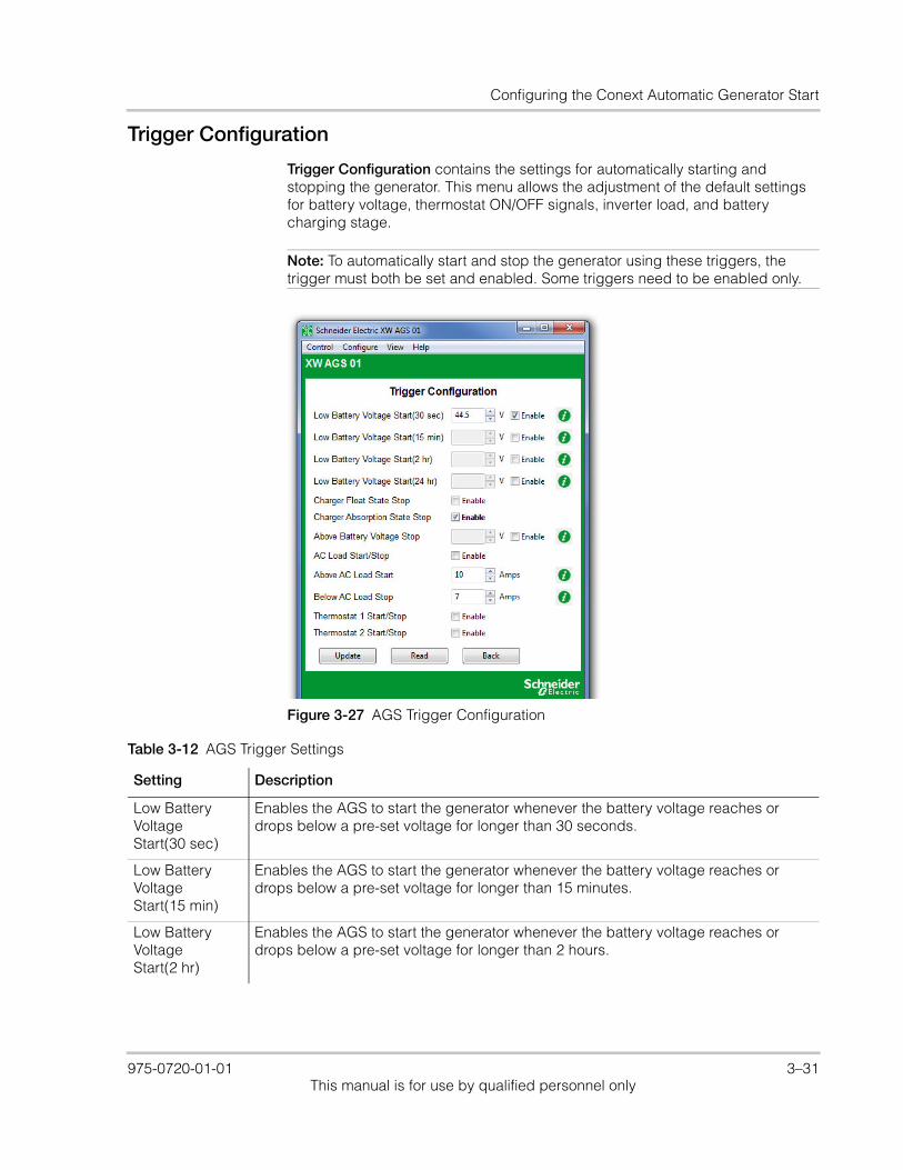
Configuring the Conext Automatic Generator Start
Trigger Configuration
Trigger Configuration contains the settings for automatically starting and stopping the generator. This menu allows the adjustment of the default settings for battery voltage, thermostat ON/OFF signals, inverter load, and battery charging stage.
Note: To automatically start and stop the generator using these triggers, the trigger must both be set and enabled. Some triggers need to be enabled only.
Figure 3-27 AGS Trigger Configuration
Table 3-12 AGS Trigger Settings
Setting Description
Low Battery Voltage Start(30 sec)
Enables the AGS to start the generator whenever the battery voltage reaches or drops below a pre-set voltage for longer than 30 seconds.
Low Battery Voltage Start(15 min)
Enables the AGS to start the generator whenever the battery voltage reaches or drops below a pre-set voltage for longer than 15 minutes.
Low Battery Voltage Start(2 hr)
Enables the AGS to start the generator whenever the battery voltage reaches or drops below a pre-set voltage for longer than 2 hours.
975-0720-01-01 3–31This manual is for use by qualified personnel only

Device Configuration
Low Battery Voltage Start(24 hr)
Enables the AGS to start the generator whenever the battery voltage reaches or drops below a pre-set voltage for longer than 24 hours.
Charger Float State Stop
When selected, enables the AGS to stop the generator when the inverter/charger has recharged the batteries to the Float stage.
Charger Absorption State Stop
When selected, enables the AGS to stop the generator when the inverter/charger has recharged the batteries to the Absorption stage.
Above Battery Voltage Stop
Enables the AGS to stop the generator whenever the battery voltage reaches a pre-set DC voltage. Whenever the generator starts automatically based on the Starting Battery Voltage, it will shut off once the Stopping Battery Voltage has been reached.
AC Load Start/Stop
Enables or disables the Start Load and Stop Load functionality of the AGS. This function enables the generator to start and stop based on the current being drawn on the inverter by the loads.
Above AC Load Start
Enables the generator to start at a specified AC load (current draw) on the inverter. This current draw must be present for 5 minutes before the generator will start. The generator will assist the inverter with powering the AC load.
Below AC Load Stop
Enables the AGS to stop the generator when the AC load falls below a specific level for 1 minute.
Thermostat 1 Start/Stop
When selected, enables the generator to start in response to a signal from a thermostat. With Temp1 enabled, the AGS will start the generator to help power the item controlled by that thermostat.
Thermostat 2 Start/Stop
When selected, enables the generator to start in response to a signal from a second thermostat.
Table 3-12 AGS Trigger Settings
Setting Description
3–32 975-0720-01-01This manual is for use by qualified personnel only

Configuring the Conext Automatic Generator Start
Multi-Unit AGS Configuration
AGS Basic Configuration provides the means to identify multiple AGS units within the same configuration.
Figure 3-28 AGS Basic Configuration
Table 3-13 AGS Trigger Settings
Setting Description
Device Name Gives each Xanbus-enabled device a unique identifiable name. This makes each device easier to identify when multiple Xanbus-enabled devices are connected together.The default device name for the AGS is “XW AGS.”
Device Number Gives each Xanbus-enabled device a unique identifiable number in addition to the name. This provides the means to use the same name, but different numbers for similar devices (such as XW AGS 01 and XW AGS 02).
AC Output Association
Tells the AGS what load to monitor for AC load triggers.
AC Input Association
Tells the AGS what other AC source or grid the Conext XW+ Inverter/Charger is connected to. The AGS uses this setting to stop the generator once the Conext XW+ Inverter/Charger transfers Configuration from the generator to the grid or alternative AC source.
Battery Association
Tells the AGS which battery bank to use for the charger based triggers.
975-0720-01-01 3–33This manual is for use by qualified personnel only

Device Configuration
Saving and Restoring Configurations
Save Configuration allows you to save the current AGS configuration. Restore Configuration allows you to restore a previously saved configuration from a file. See “Restoring a Configuration” on page 2–31 for further details.
Configuring the System Control PanelThe following section describes how to configure the System Control Panel (SCP) to suit your preferences and the requirements of the Xanbus system.
To configure the SCP:
1. On the main screen, click the SCP icon:
The SCP Basic Status window opens.
2. In the Basic Status window, click Configure
3. Click Basic Configuration.
Basic Status
The Basic Status window shows the network status of the SCP.
Generator Association
This generator name is used by the Conext XW+ to identify which generator is connected to either of the two AC inputs, AC1 or AC2. It is only necessary to change this setting in installations with more than one AGS in a system. In this case, the Generator name on each AGS needs to be unique.For example, if a generator is connected to AC2 on an Conext XW+, the generator name (e.g. Gen1, Gen2, etc.) selected for AC2 under Connections on the Conext XW+ must match the generator name assigned here.
Table 3-13 AGS Trigger Settings
Setting Description
Figure 3-29 SCP Basic Status Window
3–34 975-0720-01-01This manual is for use by qualified personnel only
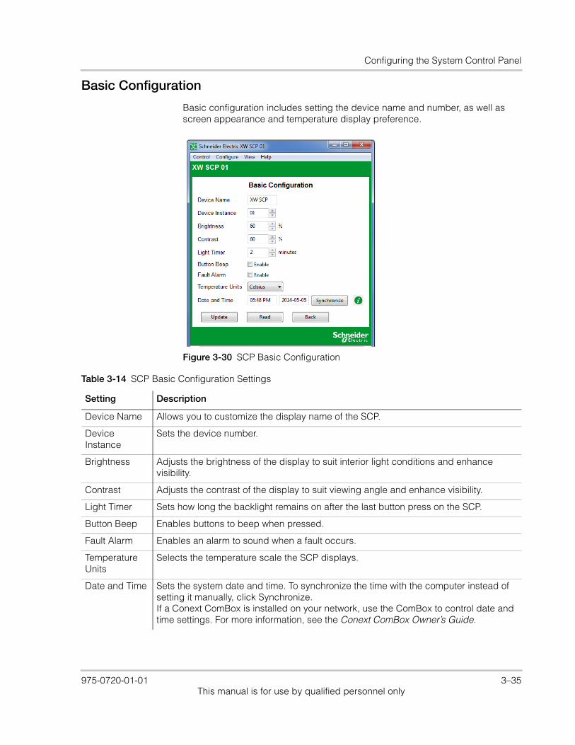
Configuring the System Control Panel
Basic Configuration
Basic configuration includes setting the device name and number, as well as screen appearance and temperature display preference.
Figure 3-30 SCP Basic Configuration
Table 3-14 SCP Basic Configuration Settings
Setting Description
Device Name Allows you to customize the display name of the SCP.
Device Instance
Sets the device number.
Brightness Adjusts the brightness of the display to suit interior light conditions and enhance visibility.
Contrast Adjusts the contrast of the display to suit viewing angle and enhance visibility.
Light Timer Sets how long the backlight remains on after the last button press on the SCP.
Button Beep Enables buttons to beep when pressed.
Fault Alarm Enables an alarm to sound when a fault occurs.
Temperature Units
Selects the temperature scale the SCP displays.
Date and Time Sets the system date and time. To synchronize the time with the computer instead of setting it manually, click Synchronize.If a Conext ComBox is installed on your network, use the ComBox to control date and time settings. For more information, see the Conext ComBox Owner’s Guide.
975-0720-01-01 3–35This manual is for use by qualified personnel only
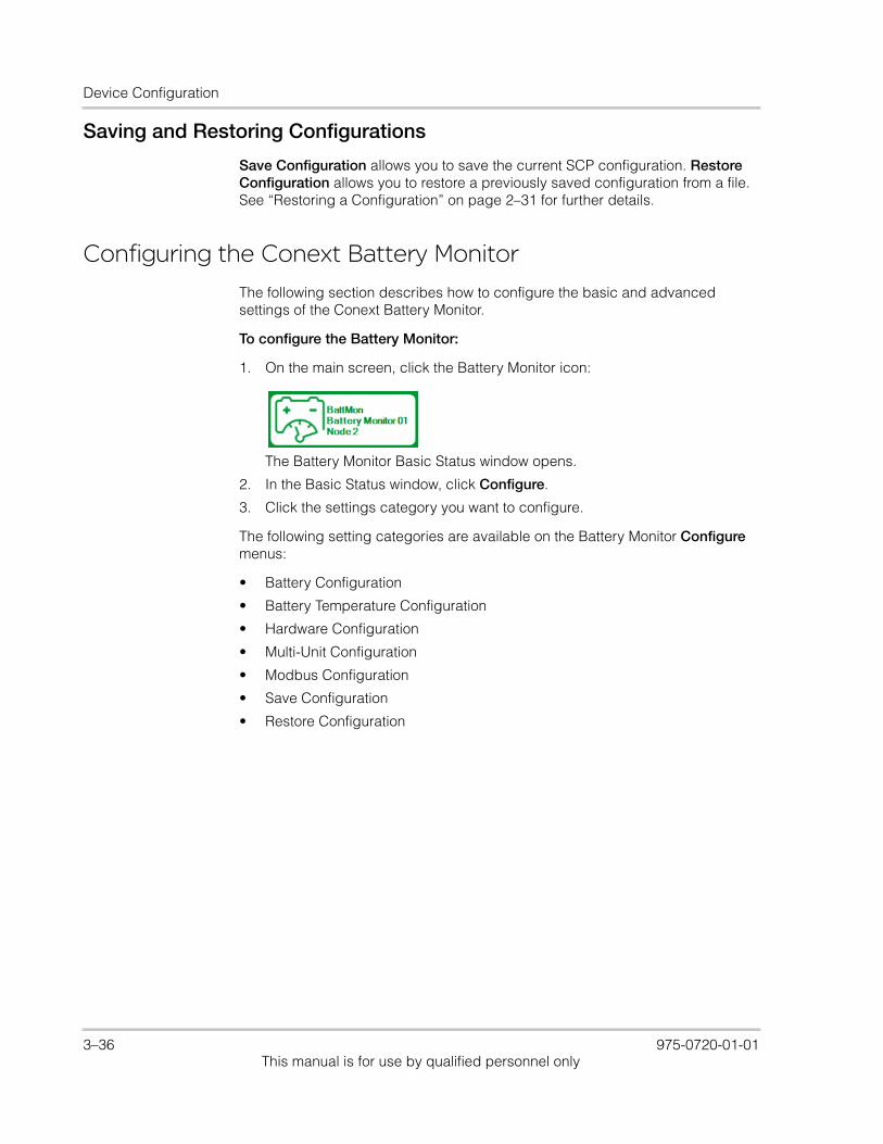
Device Configuration
Saving and Restoring Configurations
Save Configuration allows you to save the current SCP configuration. Restore Configuration allows you to restore a previously saved configuration from a file. See “Restoring a Configuration” on page 2–31 for further details.
Configuring the Conext Battery MonitorThe following section describes how to configure the basic and advanced settings of the Conext Battery Monitor.
To configure the Battery Monitor:
1. On the main screen, click the Battery Monitor icon:
The Battery Monitor Basic Status window opens.
2. In the Basic Status window, click Configure.
3. Click the settings category you want to configure.
The following setting categories are available on the Battery Monitor Configure menus:
• Battery Configuration
• Battery Temperature Configuration
• Hardware Configuration
• Multi-Unit Configuration
• Modbus Configuration
• Save Configuration
• Restore Configuration
3–36 975-0720-01-01This manual is for use by qualified personnel only

Configuring the Conext Battery Monitor
Basic Status
The Basic Status window shows the status of the Battery Monitor.
Figure 3-31 Battery Monitor Basic Status Window
975-0720-01-01 3–37This manual is for use by qualified personnel only
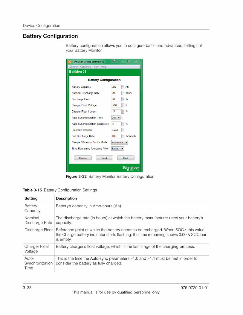
Device Configuration
Battery Configuration
Battery configuration allows you to configure basic and advanced settings of your Battery Monitor.
Figure 3-32 Battery Monitor Battery Configuration
Table 3-15 Battery Configuration Settings
Setting Description
Battery Capacity
Battery’s capacity in Amp-hours (Ah).
Nominal Discharge Rate
The discharge rate (in hours) at which the battery manufacturer rates your battery’s capacity.
Discharge Floor Reference point at which the battery needs to be recharged. When SOC< this value the Charge battery indicator starts flashing, the time remaining shows 0:00 & SOC bar is empty.
Charger Float Voltage
Battery charger’s float voltage, which is the last stage of the charging process.
Auto-Synchronization Time
This is the time the Auto-sync parameters F1.0 and F1.1 must be met in order to consider the battery as fully charged.
3–38 975-0720-01-01This manual is for use by qualified personnel only
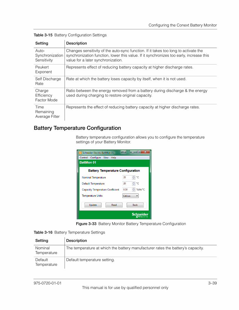
Configuring the Conext Battery Monitor
Battery Temperature Configuration
Battery temperature configuration allows you to configure the temperature settings of your Battery Monitor.
Auto-Synchronization Sensitivity
Changes sensitivity of the auto-sync function. If it takes too long to activate the synchronization function, lower this value. If it synchronizes too early, increase this value for a later synchronization.
Peukert Exponent
Represents effect of reducing battery capacity at higher discharge rates.
Self Discharge Rate
Rate at which the battery loses capacity by itself, when it is not used.
Charge Efficiency Factor Mode
Ratio between the energy removed from a battery during discharge & the energy used during charging to restore original capacity.
Time Remaining Average Filter
Represents the effect of reducing battery capacity at higher discharge rates.
Table 3-15 Battery Configuration Settings
Setting Description
Figure 3-33 Battery Monitor Battery Temperature Configuration
Table 3-16 Battery Temperature Settings
Setting Description
Nominal Temperature
The temperature at which the battery manufacturer rates the battery’s capacity.
Default Temperature
Default temperature setting.
975-0720-01-01 3–39This manual is for use by qualified personnel only
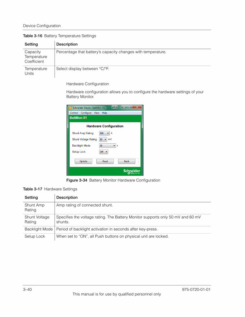
Device Configuration
Hardware Configuration
Hardware configuration allows you to configure the hardware settings of your Battery Monitor.
Capacity Temperature Coefficient
Percentage that battery’s capacity changes with temperature.
Temperature Units
Select display between °C/°F.
Table 3-16 Battery Temperature Settings
Setting Description
Figure 3-34 Battery Monitor Hardware Configuration
Table 3-17 Hardware Settings
Setting Description
Shunt Amp Rating
Amp rating of connected shunt.
Shunt Voltage Rating
Specifies the voltage rating. The Battery Monitor supports only 50 mV and 60 mV shunts.
Backlight Mode Period of backlight activation in seconds after key-press.
Setup Lock When set to “ON”, all Push buttons on physical unit are locked.
3–40 975-0720-01-01This manual is for use by qualified personnel only

Configuring the Conext Battery Monitor
Multi-Unit Configuration
Multi-unit configuration allows you to select the battery association and set the device name and instance of the Battery Monitor.
Figure 3-35 Battery Monitor Multi-Unit Configuration
Setting Description
Device Name Specifies the displayed name of the Battery Monitor. Gives each Xanbus-enabled device a unique identifiable name. This makes each device easier to identify when multiple Xanbus-enabled devices are connected together.
Device Instance
Specifies the number associated with the Battery Monitor which will appear beside the Device Name in the application. This provides the means to use the same name, but different numbers for similar devices (such as BattMon 01 and BattMon 02). If there is more than one Battery Monitor running on the system, this number must be manually changed and updated for subsequent devices. The device must be in standby mode to update this setting.
Battery Association
Tells the Battery Monitor which battery bank to use for the charger based triggers. Device must be in standby mode to update this setting.
975-0720-01-01 3–41This manual is for use by qualified personnel only
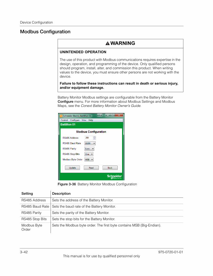
Device Configuration
Modbus Configuration
Battery Monitor Modbus settings are configurable from the Battery Monitor Configure menu. For more information about Modbus Settings and Modbus Maps, see the Conext Battery Monitor Owner’s Guide.
WARNING
UNINTENDED OPERATION
The use of this product with Modbus communications requires expertise in the design, operation, and programming of the device. Only qualified persons should program, install, alter, and commission this product. When writing values to the device, you must ensure other persons are not working with the device.
Failure to follow these instructions can result in death or serious injury, and/or equipment damage.
Figure 3-36 Battery Monitor Modbus Configuration
Setting Description
RS485 Address Sets the address of the Battery Monitor.
RS485 Baud Rate Sets the baud rate of the Battery Monitor.
RS485 Parity Sets the parity of the Battery Monitor.
RS485 Stop Bits Sets the stop bits for the Battery Monitor.
Modbus Byte Order
Sets the Modbus byte order. The first byte contains MSB (Big-Endian).
3–42 975-0720-01-01This manual is for use by qualified personnel only

4 System Logging
Chapter 4, “System Logging” contains information and procedures to use the Conext Configuration Tool system logging feature.
Topics in this chapter include:• “Introduction” on page 4–2• “Getting Started” on page 4–2• “Configuration” on page 4–3• “Running the Logger” on page 4–7• “Using the Data” on page 4–8.
975-0720-01-01 4–1This manual is for use by qualified personnel only

System Logging
IntroductionWith the system logging feature you can log any parameter broadcast from any device on the Xanbus network. The information is logged to a comma-separated values (CSV) text file, which can be imported directly into a spreadsheet program such as Microsoft Excel. You can also specify several timing parameters such as logging interval, logging duration, start of log and automatic repeating. In addition, it is possible to have the log file sent via email to a specified address once and/or sent to an FTP repository once the log is completed.
Getting Started
To start the logging feature, select Data Logger from the Conext Configuration Tool View menu (see Figure 1-11 on page 1–17). It is not possible to have a device window open while logging is in progress. Selecting Data Logger automatically closes any device windows that are open and disables the device buttons.
Figure 4-1 System Logging Window
4–2 975-0720-01-01This manual is for use by qualified personnel only

Configuration
ConfigurationThe logging configuration is displayed as a tree. The main components are All Devices (where the data to log is specified), Timing, Email and FTP. To expand each tree or sub-tree, click the plus sign beside each folder.
Selecting Fields to Log
All of the data points that are available to be logged are in the All Devices branch of the Logging Configuration tree. At the top level of the tree are all of the devices that are currently on the network. Each device’s sub-tree shows all of the messages the device is broadcasting. Some message types can be associated with different connections on the device. In these cases, the connection name is shown in brackets.
Within each message sub-tree are each of the fields that can be logged. To select a field for logging, simply click its checkbox.
It helps to have a working knowledge of each message’s structure. Some messages such as AcInStsRms may have repeating sequences of the same field names. These sequences are called tuples and the first field of the tuple identifies its meaning. For instance, in AcInStsRms, the first field of the tuple (Line) will have the value ‘Line 1’ and the second occurrence of Line will have ‘Line 2’. These identifier fields aren’t worth logging, but they can help you find indicate which Voltage, Current or Power field to select for logging.
The current values for the fields are shown in brackets so that you know what type of data is being logged.
Timing Parameters
You can configure the log timing in several ways. The following options are all possible:
• Log until the Stop button is pushed
• Log for a specific duration after the Start button is pushed
• Log for a specific duration, starting at a specific time of day
• Log for a specific duration after the Start button is pushed and then automatically resume for the same time period
• Log for a specific duration, starting at a specific time of day every day
975-0720-01-01 4–3This manual is for use by qualified personnel only

System Logging
Polling Period
You can set the logging period in seconds using a drop-down menu. The following logging periods are possible:
• 1 second (default setting)
• 2 seconds
• 5 seconds
• 10 seconds
• 1 minute
• 10 minutes
• 1 hour
Logging Duration
The logging duration is specified in hours and minutes. A logging duration of zero allows continuous logging until the Stop button is pushed.
Of course, a very long log file is not recommended as it can produce very large files which may overload spreadsheet programs such as Excel. For long-term logs, it is best to specify a logging duration and select an automatic restart.
Scheduled start
You can configure Conext Configuration Tool to start logging at a particular time of day. This capability, along with logging duration is useful for recording solar charge controller data during daylight hours. To enable Scheduled start, click the Scheduled start checkbox. This opens the Scheduled start sub-tree and enables the Time of day control to be updated.
To change the time of day, click the Time of day field and type or select the desired time.
Automatic restart
For long-term logging, use the Automatic restart feature. Automatic restart can work in two possible ways, depending on whether or not Scheduled start is set.
1. If Scheduled start is set, the next log starts at the same time the next day.
2. If Scheduled start is not set, the next log starts as soon as the last log has finished processing. This provides a nearly, but not quite continuous, log. There will be a bit of a time gap between data files. If the resultant log file is being emailed or transmitted to an FTP repository then this gap may be significant.
4–4 975-0720-01-01This manual is for use by qualified personnel only
Configuration
Email Options
Once a log is complete, Conext Configuration Tool can automatically compress it and send it off site to a specific email account. Of course, for this feature to work, it is necessary for the computer running Conext Configuration Tool to be connected to the Internet and have access to an SMTP server.
This feature requires an account with an SMTP (Simple Message Transfer Protocol) server only. It will not send from IMAP, Exchange Server, or a webmail-only email account. It can, however, send to any of those kinds of email accounts.
To enable email, select Email. This expands the Email folder and enables the following configuration fields.
Destination address
The email address that the log file is sent to.
Sending address
The address that the log file will appear to come from.
SMTP Server
The SMTP server relays the email to the destination address. You may need to ask your ISP or system administrator for email connection parameters. The server name may follow the formats “smtp.yourprovider.com” or “mail.yourprovider.com”.
Port
The default port for SMTP is 25. However, some servers may use a different port to get around firewalls.
Email Userid and Password
Depending on how your network is set up, it may be necessary to provide a userid and password for authentication. If it is, use the two fields provided to enter your userid and password.
Notify of log start
Select Notify of log start if you want an email to be sent to the destination address when logging starts. This lets the recipient know that the email connection is working and when to expect the first log file.
975-0720-01-01 4–5This manual is for use by qualified personnel only
System Logging
Troubleshooting
Getting Conext Configuration Tool to send an email can be challenging because all parameters need to be correct. Firewalls and security programs can also block email attempts even when all connection parameters are correct.
Always try a short log first with your email connection parameters to make sure that emails will go through at all before committing to a big logging session.
Security programs can block emails from Conext Configuration Tool despite allowing emails from a more recognized email program. It may be necessary to disable your virus scanning program entirely for Conext Configuration Tool to transfer log files across the Internet.
FTP Options
Another efficient way to send log files offsite is to use FTP (File Transfer Protocol). FTP can be used instead of or as well as email.
For FTP to work, the computer running Conext Configuration Tool must have a live Internet connection. There must also be an account on an FTP server that will receive the compressed log files. You may need to ask your Internet provider or system administrator for help.
To enable FTP transfer of log files, select FTP. This expands the FTP folder and enables the configuration fields.
FTP Server
This is the name of the host computer hosting the FTP repository. It generally requires a format such as ftp.yourhost.com
Port
FTP transfers usually occur on port 21 which is the default for this field. However, some FTP servers may use a different port number to get around firewalls.
Userid and Password
All connections to an FTP server require authentication with a user ID and usually a password.
Directory
The FTP server will usually put you in a directory specific to your account. However, if you want to put the log file in a subdirectory of the account’s directory, then specify the subdirectory here.
4–6 975-0720-01-01This manual is for use by qualified personnel only

Running the Logger
Passive Mode
FTP normally uses two connections, one initiated from the server and the other initiated from the client. However, some firewalls may block connections initiated from the server side. Passive mode allows files to be transferred using only the one connection.
Passive mode is the default, because of its wider utility. However, it is possible for a connection to work only in normal mode. The bottom line is: if the connection doesn’t work in one mode then try the other.
Troubleshooting
As with email, try a short test log to make sure that your connection works before committing to a longer term log.
Saving and Restoring Configurations
Setting up a log, especially one that uses email or FTP can be a complicated process, so saving the configuration to a file for later retrieval is always a good idea. There are save and load buttons at the bottom of the system logging window. The default directory for the configuration files is the same as for the log files, typically C:\User\AppData\Roaming\CnxtCfgTool\LogFiles.
It doesn’t matter what extension is used for configuration files, but .cfg is typical.
Running the Logger
Once you have selected all of the fields that you want to log and made all other configurations, you can start the log running by clicking the green Start button near the bottom of the window. Logging will either start immediately or the countdown will begin for the start of the scheduled log. Either way, the status bar at the bottom of the window shows what is going on. The data points box beside the start and stop buttons will also show the number of points logged.
To stop or cancel logging, click the red Stop button. The Stop button overrides any set logging period. If the email or FTP options are enabled, the log file will be compressed and sent as normal.
Fault Tolerance
If a device falls off the Xanbus network or stops broadcasting, the logger will continue to log but will insert blanks where data is not available. If the device comes back online and resumes broadcasting data, Conext Configuration Tool resumes logging actual data.
975-0720-01-01 4–7This manual is for use by qualified personnel only

System Logging
Limitations
There is no particular limit to the number of data points that can be logged simultaneously. Most spreadsheet programs can import up to 256 columns of data. Taking into account the time and date columns, it should be possible to log up to 254 data points.
Similarly, there is no particular limit to the length of the log file. However, earlier versions of Excel can only accept 65536 rows of data. These earlier versions (2003 and older) would be able to import an all-day log file recorded with a 2-second period but not a 1-second period.
Using the Data
All logged data goes to the Conext Configuration Tool log directory on your computer, typically in C:\User\AppData\Roaming\CnxtCfgTool\LogFiles. You can navigate directly to this folder by clicking Open Log Folder on the System Logging screen.
The log files are in a Comma-Separated Values (CSV) format that can be imported directly into any spreadsheet program. This is just a text file with one line per log entry where the values are separated by commas. Date, time and other string type values are enclosed in double quotes. Integer, floating point and null values are not.
The first five lines of the file contain header information to indicate the meaning of each column.
Device
The first header line indicates the device that the data is coming from. The identifier is the device function, followed by its instance number. For instance, Charger 01 for a charge controller.
PGN
The second line indicates the mnemonic for the PGN or Parameter Group Number. The PGN indicates the type of message from the device.
ID
The third ID line indicates which connection the PGN is associated with, if any. The ID would distinguish between PGNs for AcInStsRms for the generator from those for the grid.
4–8 975-0720-01-01This manual is for use by qualified personnel only
Using the Data
Tuple
The Tuple line is used only for fields within variable length messages from the device. These are messages that have repeated sequences of fields such as AcInStsRms that have a tuple per AC line when configured for split phase. The tuple number counts up from zero. Tuple 0 would be for line 1 and tuple 1 would be for line 2.
Signal
The fifth line from the log file header indicates the name of the field within the message as identified from the fields above.
Date and Time
The first two columns of the log file indicate the date and time respectively. The date is in yyyy-mm-dd format and the time is in 24 hour format.
975-0720-01-01 4–9This manual is for use by qualified personnel only

System Logging
4–10 975-0720-01-01This manual is for use by qualified personnel only
5 Upgrading Firmware
Chapter 5, “Upgrading Firmware” contains information about upgrading device firmware using Conext Configuration Tool.
Topics in this chapter include:• “Introduction” on page 5–2• “Downloading Firmware Files” on
page 5–2• “Starting Firmware Upgrade” on
page 5–2• “Upgrade Failures” on page 5–4
975-0720-01-01 5–1This manual is for use by qualified personnel only

Upgrading Firmware
Introduction
The firmware upgrade feature allows Conext Configuration Tool to upgrade the firmware of any Xanbus-enabled device on its connected system. It is designed to be simple to use so that all devices on the network can be upgraded with the latest available firmware appropriate to the device.
Note: A firmware upgrade may cause some configuration settings to change or revert to their default settings.To avoid deletion of your preferred configuration settings, save all device settings before performing a firmware upgrade on any device, and reload the settings after the firmware upgrade is completed.
Downloading Firmware Files
The latest firmware is available from SEsolar.com. Download the latest firmware file and save it to a local directory on your computer, for example C:\User\AppData\Roaming\CnxtCfgTool\Firmware.
Starting Firmware Upgrade
You can upgrade your firmware, downgrade your firmware to a previously saved version, or reload your current firmware by selecting Firmware Upgrade in the Configure menu.
WARNING
LIMITATIONS ON USE
During the firmware upgrade process of any device on the Xanbus network, all units on the network will cease output of power.
Do not use any device on the Xanbus network in connection with life support systems or other medical equipment or devices.
Failure to follow these instructions can result in death or serious injury.
Figure 5-1 Configure Menu
5–2 975-0720-01-01This manual is for use by qualified personnel only
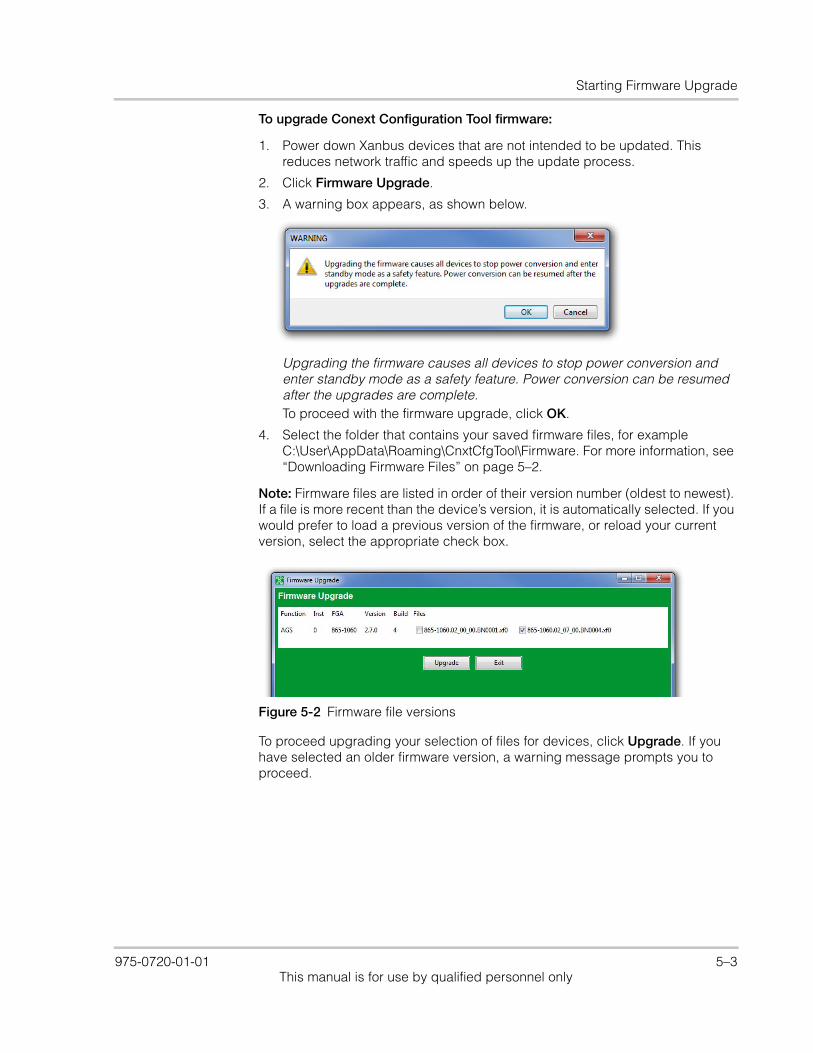
Starting Firmware Upgrade
To upgrade Conext Configuration Tool firmware:
1. Power down Xanbus devices that are not intended to be updated. This reduces network traffic and speeds up the update process.
2. Click Firmware Upgrade.
3. A warning box appears, as shown below.
Upgrading the firmware causes all devices to stop power conversion and enter standby mode as a safety feature. Power conversion can be resumed after the upgrades are complete.To proceed with the firmware upgrade, click OK.
4. Select the folder that contains your saved firmware files, for example C:\User\AppData\Roaming\CnxtCfgTool\Firmware. For more information, see “Downloading Firmware Files” on page 5–2.
Note: Firmware files are listed in order of their version number (oldest to newest). If a file is more recent than the device’s version, it is automatically selected. If you would prefer to load a previous version of the firmware, or reload your current version, select the appropriate check box.
To proceed upgrading your selection of files for devices, click Upgrade. If you have selected an older firmware version, a warning message prompts you to proceed.
Figure 5-2 Firmware file versions
975-0720-01-01 5–3This manual is for use by qualified personnel only
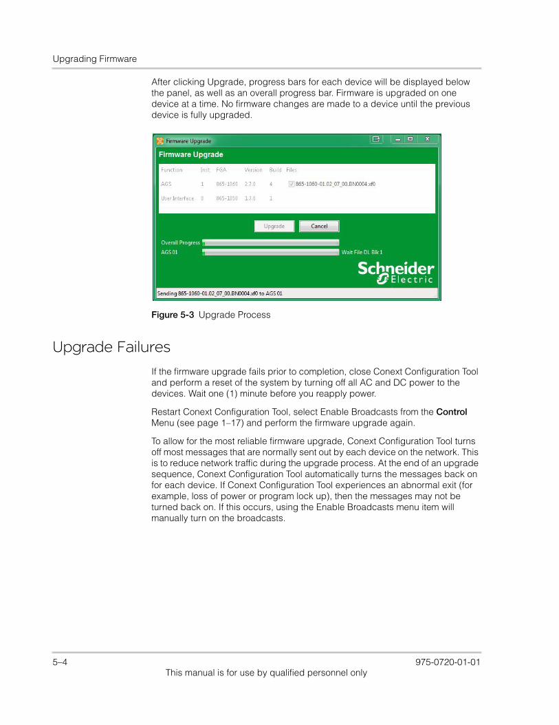
Upgrading Firmware
After clicking Upgrade, progress bars for each device will be displayed below the panel, as well as an overall progress bar. Firmware is upgraded on one device at a time. No firmware changes are made to a device until the previous device is fully upgraded.
Upgrade Failures
If the firmware upgrade fails prior to completion, close Conext Configuration Tool and perform a reset of the system by turning off all AC and DC power to the devices. Wait one (1) minute before you reapply power.
Restart Conext Configuration Tool, select Enable Broadcasts from the Control Menu (see page 1–17) and perform the firmware upgrade again.
To allow for the most reliable firmware upgrade, Conext Configuration Tool turns off most messages that are normally sent out by each device on the network. This is to reduce network traffic during the upgrade process. At the end of an upgrade sequence, Conext Configuration Tool automatically turns the messages back on for each device. If Conext Configuration Tool experiences an abnormal exit (for example, loss of power or program lock up), then the messages may not be turned back on. If this occurs, using the Enable Broadcasts menu item will manually turn on the broadcasts.
Figure 5-3 Upgrade Process
5–4 975-0720-01-01This manual is for use by qualified personnel only
A Legacy USB-to-Xanbus Adapters
Appendix A, “Legacy USB-to-Xanbus Adapters” provides information about installing older versions of the USB-to-Xanbus adapter.
975-0720-01-01 A–1This manual is for use by qualified personnel only
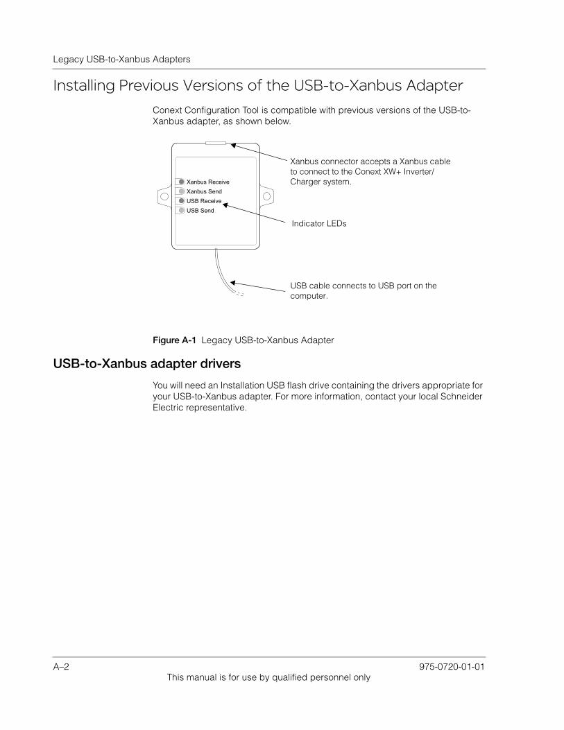
Legacy USB-to-Xanbus Adapters
Installing Previous Versions of the USB-to-Xanbus AdapterConext Configuration Tool is compatible with previous versions of the USB-to-Xanbus adapter, as shown below.
USB-to-Xanbus adapter drivers
You will need an Installation USB flash drive containing the drivers appropriate for your USB-to-Xanbus adapter. For more information, contact your local Schneider Electric representative.
Xanbus ReceiveXanbus SendUSB ReceiveUSB Send
Xanbus Diagnostic Tool
Xanbus connector accepts a Xanbus cable to connect to the Conext XW+ Inverter/Charger system.
Indicator LEDs
USB cable connects to USB port on the computer.
Figure A-1 Legacy USB-to-Xanbus Adapter
A–2 975-0720-01-01This manual is for use by qualified personnel only
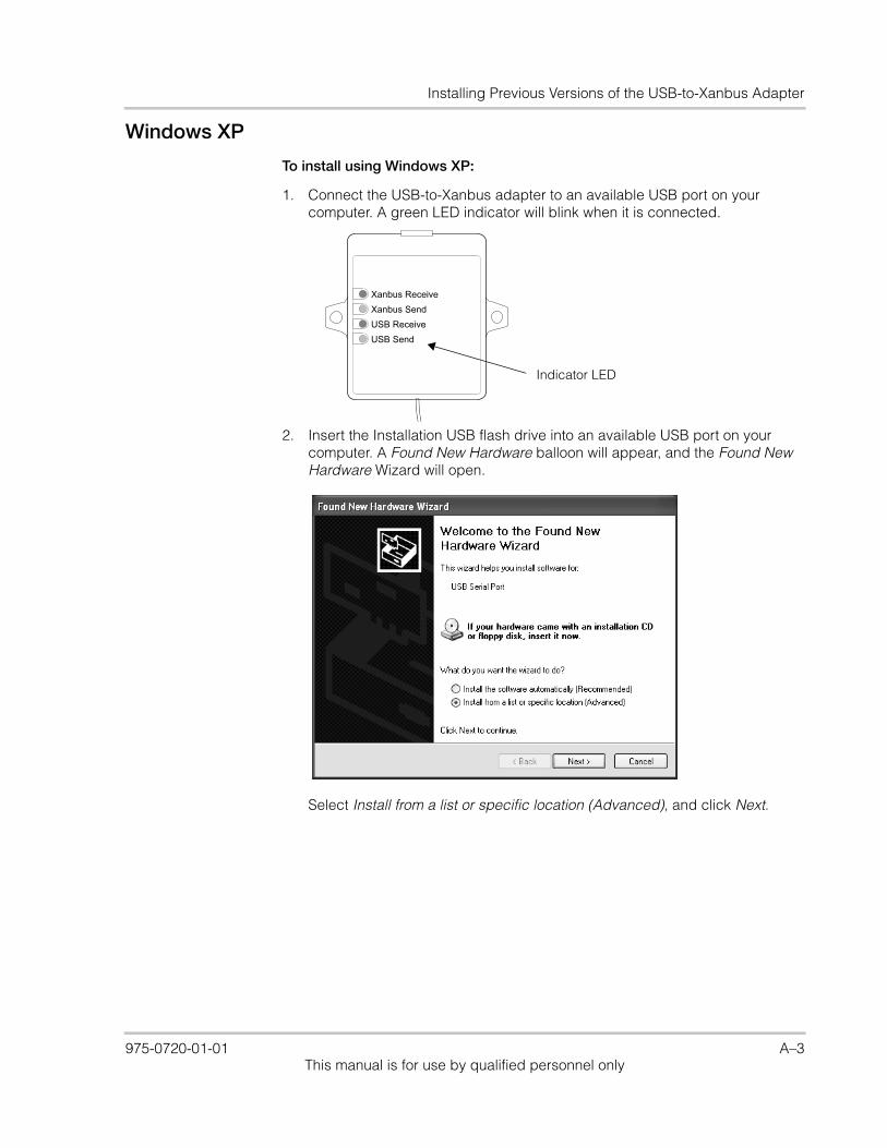
Installing Previous Versions of the USB-to-Xanbus Adapter
Windows XP
To install using Windows XP:
1. Connect the USB-to-Xanbus adapter to an available USB port on your computer. A green LED indicator will blink when it is connected.
2. Insert the Installation USB flash drive into an available USB port on your computer. A Found New Hardware balloon will appear, and the Found New Hardware Wizard will open.
Select Install from a list or specific location (Advanced), and click Next.
Xanbus ReceiveXanbus SendUSB ReceiveUSB Send
Xanbus Diagnostic ToolIndicator LED
975-0720-01-01 A–3This manual is for use by qualified personnel only
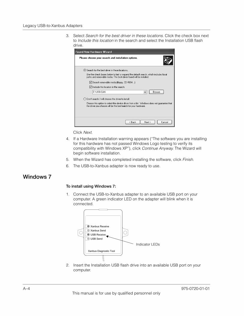
Legacy USB-to-Xanbus Adapters
3. Select Search for the best driver in these locations. Click the check box next to Include this location in the search and select the Installation USB flash drive.
Click Next.
4. If a Hardware Installation warning appears (“The software you are installing for this hardware has not passed Windows Logo testing to verify its compatibility with Windows XP”), click Continue Anyway. The Wizard will begin software installation.
5. When the Wizard has completed installing the software, click Finish.
6. The USB-to-Xanbus adapter is now ready to use.
Windows 7
To install using Windows 7:
1. Connect the USB-to-Xanbus adapter to an available USB port on your computer. A green indicator LED on the adapter will blink when it is connected.
2. Insert the Installation USB flash drive into an available USB port on your computer.
Xanbus ReceiveXanbus SendUSB ReceiveUSB Send
Xanbus Diagnostic Tool
Indicator LEDs
A–4 975-0720-01-01This manual is for use by qualified personnel only

Installing Previous Versions of the USB-to-Xanbus Adapter
3. Click on the Start button and select the Control Panel. From the Control Panel open the Device Manager.
4. The USB-to-Xanbus will be listed under Other devices as USB-CAN.
5. Right-click on the USB-CAN device, and select Update Driver Software....
6. Click Browse my computer for driver software.
7. Select the Installation USB flash drive as the search location. Click Next.
8. If a Windows Security warning message appears (“Windows can't verify the publisher of this driver software”), click Install this driver software anyway. The software installation will begin.
9. When the installation is complete, click Close.The USB-to-Xanbus adapter is now ready to use.
975-0720-01-01 A–5This manual is for use by qualified personnel only
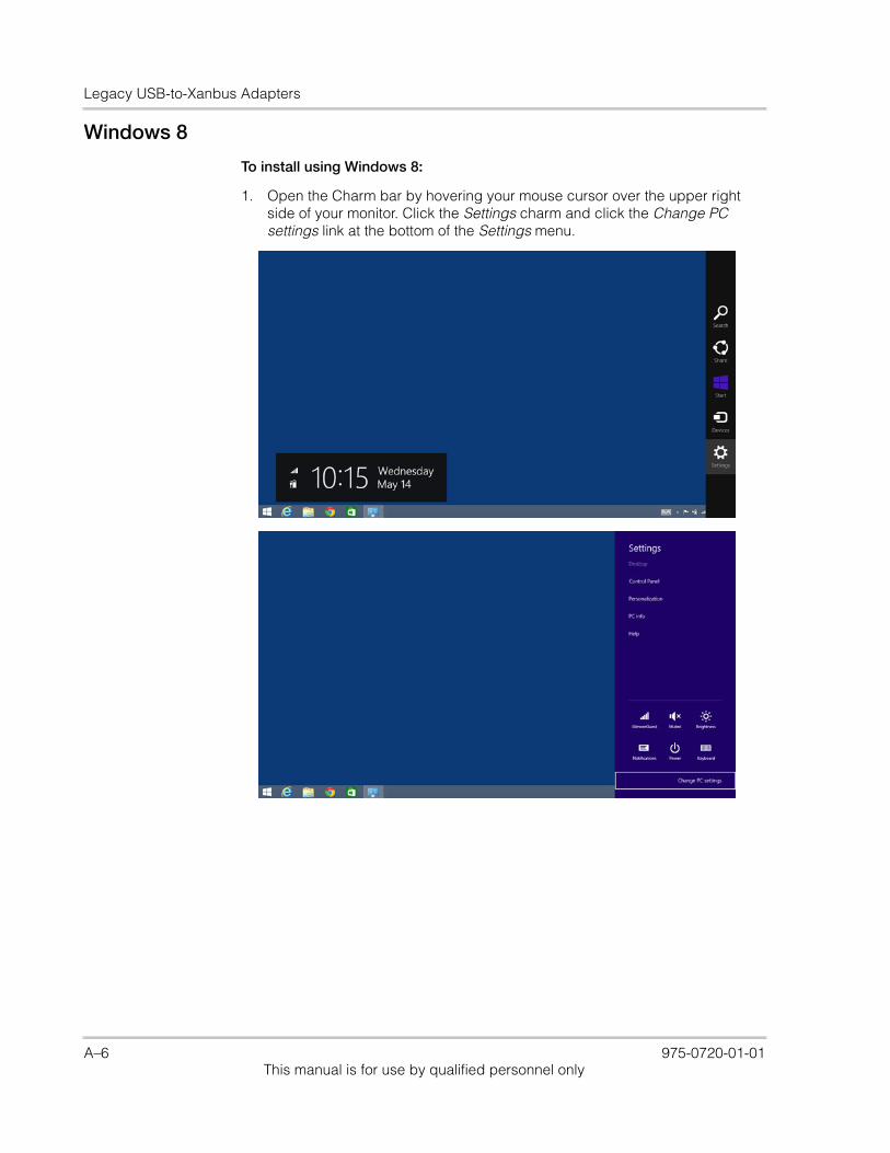
Legacy USB-to-Xanbus Adapters
Windows 8
To install using Windows 8:
1. Open the Charm bar by hovering your mouse cursor over the upper right side of your monitor. Click the Settings charm and click the Change PC settings link at the bottom of the Settings menu.
A–6 975-0720-01-01This manual is for use by qualified personnel only
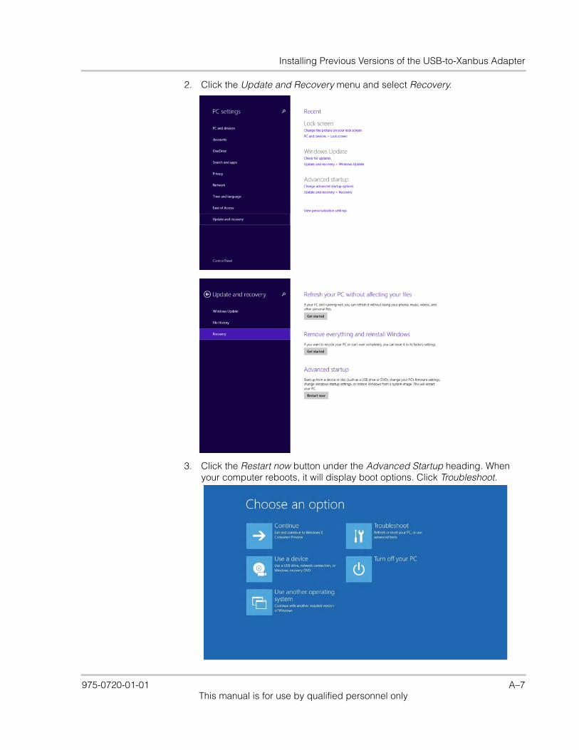
Installing Previous Versions of the USB-to-Xanbus Adapter
2. Click the Update and Recovery menu and select Recovery.
3. Click the Restart now button under the Advanced Startup heading. When your computer reboots, it will display boot options. Click Troubleshoot.
975-0720-01-01 A–7This manual is for use by qualified personnel only
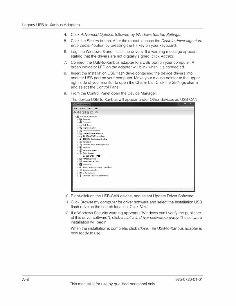
Legacy USB-to-Xanbus Adapters
4. Click Advanced Options, followed by Windows Startup Settings.
5. Click the Restart button. After the reboot, choose the Disable driver signature enforcement option by pressing the F7 key on your keyboard.
6. Login to Windows 8 and install the drivers. If a warning message appears stating that the drivers are not digitally signed, click Accept.
7. Connect the USB-to-Xanbus adapter to a USB port on your computer. A green indicator LED on the adapter will blink when it is connected.
8. Insert the Installation USB flash drive containing the device drivers into another USB port on your computer. Move your mouse pointer to the upper right side of your monitor to open the Charm bar. Click the Settings charm and select the Control Panel.
9. From the Control Panel open the Device Manager.
The device USB-to-Xanbus will appear under Other devices as USB-CAN.
10. Right-click on the USB-CAN device, and select Update Driver Software…
11. Click Browse my computer for driver software and select the Installation USB flash drive as the search location. Click Next.
12. If a Windows Security warning appears (“Windows can't verify the publisher of this driver software”), click Install this driver software anyway. The software installation will begin.
When the installation is complete, click Close. The USB-to-Xanbus adapter is now ready to use.
A–8 975-0720-01-01This manual is for use by qualified personnel only

Schwww
For ohttp:/
neider Electric.SEsolar.com
ther country details please contact your local Schneider Electric Sales Representative or visit our website at:/www.schneider-electric.com/sites/corporate/en/support/operations/local-operations/local-operations.page
Printed in China