Conext XW+ Power Distribution Panel Installation...
4
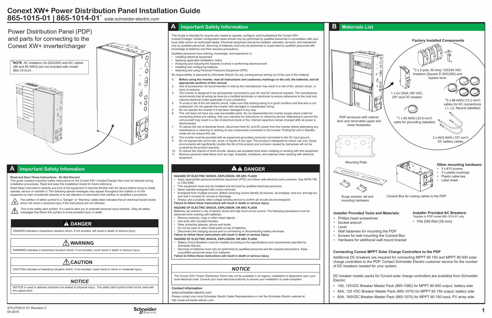
975-0709-01-01 Revision C 05-2015 1 solar.schneider-electric.com Conext XW+ Power Distribution Panel Installation Guide 865-1015-01 | 865-1014-01 * Contact Information solar.schneider-electric.com Please contact your local Schneider Electric Sales Representative or visit the Schneider Electric website at: http://solar.schneider-electric.com A Important Safety Information A Important Safety Infomation B Materials List Conduit Box for routing cables to the PDP Mounting Plate 2 x #4/0 AWG (107 mm²) DC battery cables *5 x #6 AWG (13.3 mm²) cables for AC connections: L1, L2, Neutral (labelled) *1 x #2 AWG (33.6 mm²) cable for grounding (labelled) PDP enclosure with cabinet door and removable upper and lower faceplates 1 x GJ 250A 160 VDC, 3/8" stud DC breaker *3 x 2-pole, 60 Amp 120/240 VAC breakers (Square D QOU260) and bypass lever Surge arrestor rail and mounting hardware Other mounting hardware: • 3 x #10 screws • 3 x plastic bushings • Plastic cable ties • Label sheet Factory Installed Components Installer Provided Tools and Materials: • Phillips head screwdriver • Socket wrench • Level • Wall fasteners for mounting the PDP • Screws for wall mounting the Conduit Box • Hardware for additional wall mount bracket Installer Provided AC Breakers: *Applies to PDP model 865-1014-01 only • Fits DIN Rail (35 mm) Connecting Conext MPPT Solar Charge Controllers to the PDP Additional DC breakers are required for connecting MPPT 60 150 and MPPT 80 600 solar charge controllers to the PDP. Contact Schneider Electric customer service for the number of DC breakers needed for your system. DC breaker master packs for Conext solar charge controllers are available from Schneider Electric: • 100, 125VDC Breaker Master Pack (865-1080) for MPPT 80 600 output, battery side • 80A, 125 VDC Breaker Master Pack (865-1070) for MPPT 60 150 output, battery side • 60A, 160VDC Breaker Master Pack (865-1075) for MPPT 60 150 input, PV array side *NOTE: AC breakers (3x QOU260) and AC cables (#6 and #2 AWG) are not included with model 865-1014-01. This Guide is intended for anyone who needs to operate, configure, and troubleshoot the Conext XW+ Inverter/Charger. Certain configuration tasks should only be performed by qualified personnel in consultation with your local utility and/or an authorized dealer. Electrical equipment should be installed, operated, serviced, and maintained only by qualified personnel. Servicing of batteries must only be performed or supervised by qualified personnel with knowledge of batteries and their required precautions. Qualified personnel have training, knowledge, and experience in: • Installing electrical equipment • Applying applicable installation codes • Analyzing and reducing the hazards involved in performing electrical work • Installing and configuring batteries • Selecting and using Personal Protective Equipment (PPE) No responsibility is assumed by Schneider Electric for any consequences arising out of the use of this material. HAZARD OF ELECTRIC SHOCK, EXPLOSION, OR ARC FLASH • Apply appropriate personal protective equipment (PPE) and follow safe electrical work practices. See NFPA 70E or CSA Z462. • This equipment must only be installed and serviced by qualified electrical personnel. • Never operate energized with covers removed • Energized from multiple sources. Before removing covers identify all sources, de-energize, lock-out, and tag-out and wait 2 minutes for circuits to discharge • Always use a properly rated voltage sensing device to confirm all circuits are de-energized. Failure to follow these instructions will result in death or serious injury. DANGER HAZARD OF ELECTRIC SHOCK, EXPLOSION, OR ARC FLASH Batteries can present a risk of electric shock and high short-circuit current. The following precautions must be observed when working with batteries: • Remove watches, rings or other metal objects. • Use tools with insulated handles. • Wear protective glasses, gloves and boots. • Do not lay tools or other metal parts on top of batteries. • Disconnect the charging source prior to connecting or disconnecting battery terminals. Failure to follow these instructions will result in death or serious injury. HAZARD OF ELECTRIC SHOCK, EXPLOSION, OR ARC FLASH • Battery Circuit Breakers must be installed according to the specifications and requirements specified by Schneider Electric. • Servicing of batteries must only be performed by qualified personnel and the required precautions. Keep unqualified personnel away from batteries. Failure to follow these instructions will result in death or serious injury. 1. Before using the inverter, read all instructions and cautionary markings on the unit, the batteries, and all appropriate sections of this manual. 2. Use of accessories not recommended or sold by the manufacturer may result in a risk of fire, electric shock, or injury to persons. 3. The inverter is designed to be permanently connected to your AC and DC electrical systems. The manufacturer recommends that all wiring be done by a certified technician or electrician to ensure adherence to the local and national electrical codes applicable in your jurisdiction. 4. To avoid a risk of fire and electric shock, make sure that existing wiring is in good condition and that wire is not undersized. Do not operate the inverter with damaged or substandard wiring. 5. Do not operate the inverter if it has been damaged in any way. 6. This unit does not have any user-serviceable parts. Do not disassemble the inverter except where noted for connecting wiring and cabling. See your warranty for instructions on obtaining service. Attempting to service the unit yourself may result in a risk of electrical shock or fire. Internal capacitors remain charged after all power is disconnected. 7. To reduce the risk of electrical shock, disconnect both AC and DC power from the inverter before attempting any maintenance or cleaning or working on any components connected to the inverter. Putting the unit in Standby mode will not reduce this risk. 8. The inverter must be provided with an equipment-grounding conductor connected to the AC input ground. 9. Do not expose this unit to rain, snow, or liquids of any type. This product is designed for indoor use only. Damp environments will significantly shorten the life of this product and corrosion caused by dampness will not be covered by the product warranty. 10. To reduce the chance of short-circuits, always use insulated tools when installing or working with this equipment. 11. Remove personal metal items such as rings, bracelets, necklaces, and watches when working with electrical equipment. DANGER indicates a hazardous situation which, if not avoided, will result in death or serious injury. DANGER WARNING indicates a hazardous situation which, if not avoided, could result in death or serious injury. WARNING CAUTION indicates a hazardous situation which, if not avoided, could result in minor or moderate injury. CAUTION NOTICE is used to address practices not related to physical injury.. The safety alert symbol shall not be used with this signal word. NOTICE Read and Save These Instructions - Do Not Discard This guide contains important safety instructions for the Conext XW+ Inverter/Charger that must be followed during installation procedures. Read and keep this Installation Guide for future reference. Read these instructions carefully and look at the equipment to become familiar with the device before trying to install, operate, service or maintain it. The following special messages may appear throughout this bulletin or on the equipment to warn of potential hazards or to call attention to information that clarifies or simplifies a procedure. The addition of either symbol to a “Danger” or “Warning” safety label indicates that an electrical hazard exists which will result in personal injury if the instructions are not followed. This is the safety alert symbol. It is used to alert you to potential personal injury hazards. Obey all safety messages that follow this symbol to avoid possible injury or death. The Conext XW+ Power Distribution Panel may not be available in all regions; installation is dependent upon your local electrical code. Consult your local electrical authority to ensure your installation is code-compliant. NOTICE Power Distribution Panel (PDP) and parts for connecting to the Conext XW+ inverter/charger
Transcript of Conext XW+ Power Distribution Panel Installation...
975-0709-01-01 Revision C05-2015 1
solar.schneider-electric.comConext XW+ Power Distribution Panel Installation Guide865-1015-01 | 865-1014-01*
Contact Informationsolar.schneider-electric.comPlease contact your local Schneider Electric Sales Representative or visit the Schneider Electric website at:http://solar.schneider-electric.com
A Important Safety Information
A Important Safety Infomation
B Materials List
Conduit Box for routing cables to the PDP
Mounting Plate
2 x #4/0 AWG (107 mm²) DC battery cables
*5 x #6 AWG (13.3 mm²) cables for AC connections: L1, L2, Neutral (labelled)
*1 x #2 AWG (33.6 mm²) cable for grounding (labelled)
PDP enclosure with cabinet door and removable upper and
lower faceplates
1 x GJ 250A 160 VDC, 3/8" stud DC breaker
*3 x 2-pole, 60 Amp 120/240 VAC breakers (Square D QOU260) and
bypass lever
Surge arrestor rail andmounting hardware
Other mounting hardware:• 3 x #10 screws• 3 x plastic bushings• Plastic cable ties• Label sheet
Factory Installed Components
Installer Provided Tools and Materials:• Phillips head screwdriver• Socket wrench• Level• Wall fasteners for mounting the PDP• Screws for wall mounting the Conduit Box• Hardware for additional wall mount bracket
Installer Provided AC Breakers:*Applies to PDP model 865-1014-01 only
• Fits DIN Rail (35 mm)
Connecting Conext MPPT Solar Charge Controllers to the PDPAdditional DC breakers are required for connecting MPPT 60 150 and MPPT 80 600 solar charge controllers to the PDP. Contact Schneider Electric customer service for the number of DC breakers needed for your system.
DC breaker master packs for Conext solar charge controllers are available from Schneider Electric:• 100, 125VDC Breaker Master Pack (865-1080) for MPPT 80 600 output, battery side• 80A, 125 VDC Breaker Master Pack (865-1070) for MPPT 60 150 output, battery side• 60A, 160VDC Breaker Master Pack (865-1075) for MPPT 60 150 input, PV array side
*NOTE: AC breakers (3x QOU260) and AC cables (#6 and #2 AWG) are not included with model 865-1014-01.
This Guide is intended for anyone who needs to operate, configure, and troubleshoot the Conext XW+ Inverter/Charger. Certain configuration tasks should only be performed by qualified personnel in consultation with your local utility and/or an authorized dealer. Electrical equipment should be installed, operated, serviced, and maintained only by qualified personnel. Servicing of batteries must only be performed or supervised by qualified personnel with knowledge of batteries and their required precautions. Qualified personnel have training, knowledge, and experience in:• Installing electrical equipment• Applying applicable installation codes• Analyzing and reducing the hazards involved in performing electrical work• Installing and configuring batteries• Selecting and using Personal Protective Equipment (PPE)No responsibility is assumed by Schneider Electric for any consequences arising out of the use of this material.
HAZARD OF ELECTRIC SHOCK, EXPLOSION, OR ARC FLASH• Apply appropriate personal protective equipment (PPE) and follow safe electrical work practices. See NFPA 70E
or CSA Z462.• This equipment must only be installed and serviced by qualified electrical personnel. • Never operate energized with covers removed• Energized from multiple sources. Before removing covers identify all sources, de-energize, lock-out, and tag-out
and wait 2 minutes for circuits to discharge• Always use a properly rated voltage sensing device to confirm all circuits are de-energized.Failure to follow these instructions will result in death or serious injury.
DANGER
HAZARD OF ELECTRIC SHOCK, EXPLOSION, OR ARC FLASHBatteries can present a risk of electric shock and high short-circuit current. The following precautions must be observed when working with batteries:• Remove watches, rings or other metal objects.• Use tools with insulated handles.• Wear protective glasses, gloves and boots.• Do not lay tools or other metal parts on top of batteries.• Disconnect the charging source prior to connecting or disconnecting battery terminals.Failure to follow these instructions will result in death or serious injury.HAZARD OF ELECTRIC SHOCK, EXPLOSION, OR ARC FLASH• Battery Circuit Breakers must be installed according to the specifications and requirements specified by
Schneider Electric.• Servicing of batteries must only be performed by qualified personnel and the required precautions. Keep
unqualified personnel away from batteries.Failure to follow these instructions will result in death or serious injury.
1. Before using the inverter, read all instructions and cautionary markings on the unit, the batteries, and all appropriate sections of this manual.
2. Use of accessories not recommended or sold by the manufacturer may result in a risk of fire, electric shock, or injury to persons.
3. The inverter is designed to be permanently connected to your AC and DC electrical systems. The manufacturer recommends that all wiring be done by a certified technician or electrician to ensure adherence to the local and national electrical codes applicable in your jurisdiction.
4. To avoid a risk of fire and electric shock, make sure that existing wiring is in good condition and that wire is not undersized. Do not operate the inverter with damaged or substandard wiring.
5. Do not operate the inverter if it has been damaged in any way.6. This unit does not have any user-serviceable parts. Do not disassemble the inverter except where noted for
connecting wiring and cabling. See your warranty for instructions on obtaining service. Attempting to service the unit yourself may result in a risk of electrical shock or fire. Internal capacitors remain charged after all power is disconnected.
7. To reduce the risk of electrical shock, disconnect both AC and DC power from the inverter before attempting any maintenance or cleaning or working on any components connected to the inverter. Putting the unit in Standby mode will not reduce this risk.
8. The inverter must be provided with an equipment-grounding conductor connected to the AC input ground.9. Do not expose this unit to rain, snow, or liquids of any type. This product is designed for indoor use only. Damp
environments will significantly shorten the life of this product and corrosion caused by dampness will not be covered by the product warranty.
10. To reduce the chance of short-circuits, always use insulated tools when installing or working with this equipment.11. Remove personal metal items such as rings, bracelets, necklaces, and watches when working with electrical
equipment.
DANGER indicates a hazardous situation which, if not avoided, will result in death or serious injury.
DANGER
WARNING indicates a hazardous situation which, if not avoided, could result in death or serious injury.
WARNING
CAUTION indicates a hazardous situation which, if not avoided, could result in minor or moderate injury.
CAUTION
NOTICE is used to address practices not related to physical injury.. The safety alert symbol shall not be used with this signal word.
NOTICE
Read and Save These Instructions - Do Not DiscardThis guide contains important safety instructions for the Conext XW+ Inverter/Charger that must be followed during installation procedures. Read and keep this Installation Guide for future reference. Read these instructions carefully and look at the equipment to become familiar with the device before trying to install, operate, service or maintain it. The following special messages may appear throughout this bulletin or on the equipment to warn of potential hazards or to call attention to information that clarifies or simplifies a procedure.
The addition of either symbol to a “Danger” or “Warning” safety label indicates that an electrical hazard exists which will result in personal injury if the instructions are not followed.
This is the safety alert symbol. It is used to alert you to potential personal injury hazards. Obey all safety messages that follow this symbol to avoid possible injury or death.
The Conext XW+ Power Distribution Panel may not be available in all regions; installation is dependent upon your local electrical code. Consult your local electrical authority to ensure your installation is code-compliant.
NOTICE
Power Distribution Panel (PDP) and parts for connecting to the Conext XW+ inverter/charger
C
M
Y
CM
MY
CY
CMY
K
2Copyright © 2014-2015 Schneider Electric. All Rights Reserved. All trademarks are owned by Schneider Electric Industries SAS or its affiliated companies.
solar.schneider-electric.comConext Power Distribution Panel Installation Guide
865-1015-01 | 865-1014-01*
C Knockout Dimensions D Installing Wall Brackets
44.6 mm
Inner: 2" trade (62.7 mm)Outer: 3" trade (90.0 mm)
Inner: 1/2" trade (22.2 mm or PG16)Outer: 3/4" trade (28.0 mm)
Cable Management AnchorsFits 8 mm wide cable ties
Ground Bus Bar
DC Negative Bus Bar
Ground Bus Bar
AC Neutral Bus Bar
Raceway for routing Xanbus, AC Sync, Aux, and BTS cables between inverters
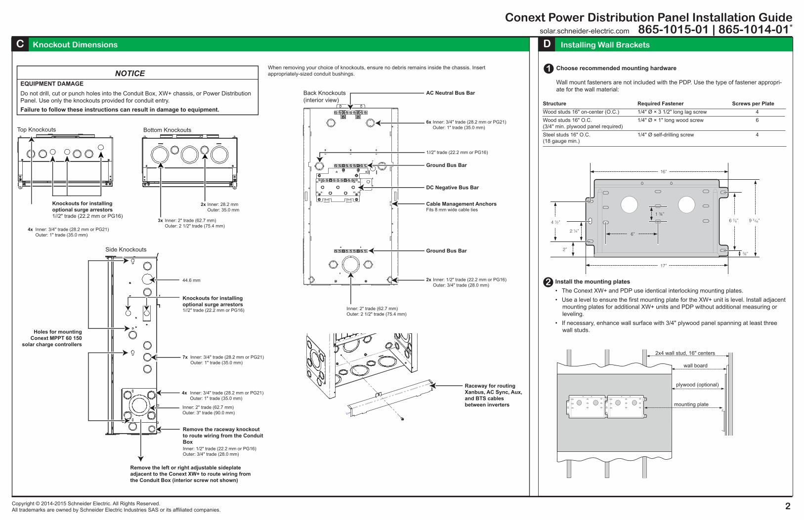
When removing your choice of knockouts, ensure no debris remains inside the chassis. Insert appropriately-sized conduit bushings.
Side Knockouts
Holes for mounting Conext MPPT 60 150
solar charge controllers
Knockouts for installing optional surge arrestors1//2" trade (22.2 mm or PG16)
Remove the left or right adjustable sideplate adjacent to the Conext XW+ to route wiring from the Conduit Box (interior screw not shown)
Remove the raceway knockout to route wiring from the Conduit Box
EQUIPMENT DAMAGEDo not drill, cut or punch holes into the Conduit Box, XW+ chassis, or Power Distribution Panel. Use only the knockouts provided for conduit entry.Failure to follow these instructions can result in damage to equipment.
NOTICE
Top Knockouts
Knockouts for installing optional surge arrestors1//2" trade (22.2 mm or PG16)
Inner: 2" trade (62.7 mm)Outer: 2 1/2" trade (75.4 mm)
Bottom Knockouts
Inner: 3/4" trade (28.2 mm or PG21)Outer: 1" trade (35.0 mm)
7x
Inner: 3/4" trade (28.2 mm or PG21)Outer: 1" trade (35.0 mm)
4x
3x
Inner: 28.2 mmOuter: 35.0 mm
2x
Inner: 3/4" trade (28.2 mm or PG21)Outer: 1" trade (35.0 mm)
4x
Inner: 2" trade (62.7 mm)Outer: 2 1/2" trade (75.4 mm)
Inner: 3/4" trade (28.2 mm or PG21)Outer: 1" trade (35.0 mm)
6x
1//2" trade (22.2 mm or PG16)
Back Knockouts(interior view)
Inner: 1/2" trade (22.2 mm or PG16)Outer: 3/4" trade (28.0 mm)
2x Install the mounting plates• The Conext XW+ and PDP use identical interlocking mounting plates.• Use a level to ensure the first mounting plate for the XW+ unit is level. Install adjacent
mounting plates for additional XW+ units and PDP without additional measuring or leveling.
• If necessary, enhance wall surface with 3/4" plywood panel spanning at least three wall studs.
Choose recommended mounting hardware
Wall mount fasteners are not included with the PDP. Use the type of fastener appropri-ate for the wall material:
Structure Required Fastener Screws per PlateWood studs 16" on-center (O.C.) 1/4" Ø × 3 1/2" long lag screw 4Wood studs 16" O.C. 1/4" Ø × 1" long wood screw 6(3/4" min. plywood panel required) Steel studs 16" O.C. 1/4" Ø self-drilling screw 4(18 gauge min.)
16”
4 ½”
2”
6”
1 ¾”
17”
6 7 8” 9 3 16”
2 ¼”
¾”
1
2x4 wall stud, 16" centers
wall board
plywood (optional)
mounting plate
C
M
Y
CM
MY
CY
CMY
K

3
solar.schneider-electric.comConext Power Distribution Panel Installation Guide865-1015-1 | 865-1014-01*
975-0709-01-01 Revision C05-2015
G Installing the Conduit BoxF Removing the PDP Door and FaceplatesE Wall Mounting the PDP
H Wiring the PDP
For detailed mounting instructions, see the Conext Conduit Box Installation Guide
Mount the Conduit Box to the bottom of the XW+ inverter/charger and secure to the wall.Remove the PDP door
Remove the top and bottom screws holding the door in place
To access the wiring and breakers, remove the upper and lower faceplates on the PDP
1
Optional: To mount the door on the other side of the unit, remove the top and bottom screws holding the pins in place and reattach on the opposite side.
Door swing out distance:25" (650 mm)
Remove breaker knockouts as needed
Elastic retaining strap for storing manuals
AC1
AC2
Event
Equalize
kW
ACharging
!
Inverting
AC1
AC2
Event
Equalize
kW
ACharging
!
Inverting
For detailed mounting instructions, see the Conext XW+ Inverter/Charger Installation Guide
Align flange withbottom edge of mounting plate
Secure to wall
Wall mount the Conext XW+
Before mounting the PDP, attach the Conext XW+ to the mounting plate as shown.
Wall mount the PDP
DAMAGE TO EQUIPMENTBefore releasing the full weight of the unit, make sure the PDP is seated properly on the mounting plate.Failure to follow these instructions can result in minor or moderate injury.
CAUTION
1
1. Align the flange on the back of the PDP with the bottom edge of the mounting plate and lower the PDP onto the plate.
2. Secure the PDP to the wall with two #10 self-tapping screws in the bracket on the top of the unit.
H
The PDP models 865-1015-01 come with DC battery cables, AC cables, and ground cables factory-installed, labelled and ready for connection.
For detailed instructions and wiring diagrams, see the Conext XW+ Inverter/Charger Installation Guide.
C
M
Y
CM
MY
CY
CMY
K

4Copyright © 2014-2015 Schneider Electric. All Rights Reserved. All trademarks are owned by Schneider Electric Industries SAS or its affiliated companies.
solar.schneider-electric.comConext Power Distributuion Panel Installation Guide
865-1015-01 | 865-1014-01*
I Installing the Surge Arrestor Rail (Optional)
The surge arrestor rail is optional to install.
Attach the side brackets to the metal studs using the nuts provided.
Attach the surge arrestors (not provided with the PDP), to the rail, feeding the wires through the cutouts.
Attach the rail to the side brackets using the four screws and washers provided.
Mounting considerations: • If you install more than six AC breakers, there may not be enough room for the surge
arrestor rail. In this case, use the appropriate top or side knockouts for installing the surge arrestors individually (see B – Knockout Dimensions).
• If you are mounting MPPT charge controllers on the side of the PDP, use the top knock-outs for installing surge arrestors.
The following surge arrestor devices are available from Schneider Electric:• Square D SDSA1175• Square D SDSA3650
Exclusion for DocumentationUNLESS SPECIFICALLY AGREED TO IN WRITING, SELLER
(A) MAKES NO WARRANTY AS TO THE ACCURACY, SUFFICIENCY OR SUITABILITY OF ANY TECHNICAL OR OTHER INFORMATION PROVIDED IN ITS MANUALS OR OTHER DOCUMENTATION;
(B) ASSUMES NO RESPONSIBILITY OR LIABILITY FOR LOSSES, DAMAGES, COSTS, OR EXPENSES, WHETHER SPECIAL, DIRECT, INDIRECT, CONSEQUENTIAL OR INCIDENTAL, WHICH MIGHT ARISE OUT OF THE USE OF SUCH INFORMATION. THE USE OF ANY SUCH INFORMATION WILL BE ENTIRELY AT THE USER’S RISK, AND
(C) REMINDS YOU THAT IF THIS MANUAL IS IN ANY LANGUAGE OTHER THAN ENGLISH, ALTHOUGH STEPS HAVE BEEN TAKEN TO MAINTAIN THE ACCURACY OF THE TRANSLATION, THE ACCURACY CANNOT BE GUARANTEED, APPROVED CONTENT IS CONTAINED WITH THE ENGLISH LANGUAGE VERSION WHICH IS POSTED AT SOLAR.SCHNEIDER-ELECTRIC.COM.
The following Conext XW+ accessory kits are available for connecting second and third inverter/chargers to the Conext PDP:• Conext XW+ Connection Kit for INV2 INV3 PDP (864-1020-02)• Conext XW+ 120/240V VAC Breaker Kit (865-1215-01)• Conext XW+ Three-Phase Breaker Kit (865-1315-01)
DJ Additional PDP Accessory Kits
C
M
Y
CM
MY
CY
CMY
K