CONESVILLE POWER PLANT FOR THE ASH POND COMPLEX AEP ...€¦ · American Electric Power Conesville...
77
Transcript of CONESVILLE POWER PLANT FOR THE ASH POND COMPLEX AEP ...€¦ · American Electric Power Conesville...


CONESVILLE POWER PLANT
EMERGENCY ACTION PLAN FOR THE ASH POND COMPLEX
PREPARED FOR
AEP GENERATION RESOURCES

American Electric Power Conesville Power Plant Emergency Action Plan January 16, 2018 TABLE OF CONTENTS
ii
TABLE OF CONTENTS
Page TABLE OF CONTENTS................................................................................................................... ii
1.1 General ...................................................................................................................................... 3
1.2 Sample Messages .................................................................................................................... 3
1.2.1 “Monitor” – Nonfailure Emergency Condition .................................................................. 3
1.2.2 “Watch” – Potential Failure Condition ............................................................................... 4
1.2.3 “Warning” – Failure is Imminent or Failure Has Occurred Condition ............................... 5
2.0 STATEMENT OF PURPOSE ................................................................................................... 7
3.0 PROJECT DESCRIPTION ....................................................................................................... 8
Figure 1: Site Location Map ........................................................................................................... 10
Figure 2: Site Sketch ....................................................................................................................... 11
4.0 EMERGENCY CONDITIONS AND CLASSIFICATION ............................................... 12
4.1 “Monitor”: Non-Failure Emergency Condition .............................................................. 12
4.2 “Watch”: Potential Failure Condition ................................................................................ 12
4.3 “Warning”: Failure is Imminent or Failure has Occurred Condition ........................... 13
5.0 GENERAL RESPONSIBILITIES .......................................................................................... 14
5.1 Dam Owner Responsibilities ............................................................................................... 14
5.2 On-Site Emergency Personnel Responsibilities ................................................................ 15
5.2.1 Conesville – Team Leader – Emergency Response Leader .............................................. 15
5.3 Responsibility for Notification and Sample Messages .................................................... 16
5.4 Public Information/News Media ....................................................................................... 17
5.5 Responsibility for Evacuation ............................................................................................. 17
5.5.1 Coshocton County EMA Directors – Primary Responsibility ......................................... 17
5.5.2 Coshocton County Sheriff – Primary Responsibility........................................................ 17
5.5.3 Coshocton Police Department – Secondary Responsibility.............................................. 17
5.6 Responsibility for Duration, Security, Termination and Follow-Up ............................. 18
5.6.1 Duration ............................................................................................................................ 18
5.6.2 Security ............................................................................................................................. 18
5.6.3 Termination ....................................................................................................................... 18
5.6.4 Follow-Up Evaluation ....................................................................................................... 19
American Electric Power Conesville Power Plant Emergency Action Plan January 16, 2018 TABLE OF CONTENTS
iii
5.7 Responsibility of the EAP Coordinator ............................................................................. 19
5.8 Duties and Responsibilities ................................................................................................. 20
5.8.1 Duties and Responsibilities for “Monitor” Emergency Condition: Nonfailure Emergency..................................................................................................................................................... 20
5.8.2 Duties and Responsibilities for Condition “Watch”: Potential Failure ........................... 20
5.8.3 Duties and Responsibilities for Condition “Warning”: Imminent Failure or Failure of the Dam ............................................................................................................................................. 21
6.0 PREPAREDNESS ..................................................................................................................... 22
6.1 Access to the Site ................................................................................................................... 22
6.2 Surveillance ............................................................................................................................ 22
6.3 Emergency Corrective Measures ........................................................................................ 23
6.3.1 High Pool Levels/Overtopping Condition ........................................................................ 23
6.3.2 Leakage Condition ............................................................................................................ 23
6.3.3 Slumping/Sliding of Embankment Condition ................................................................... 24
6.3.4 Sinkhole Condition ........................................................................................................... 24
6.3.5 Severe Downstream Erosion or Minor Structural Damage .............................................. 24
6.4 Response During Periods of Darkness .............................................................................. 24
6.5 Response During Weekends and Holidays....................................................................... 25
6.6 Response During Periods of Adverse Weather ................................................................ 25
6.7 Alternative Systems of Communication ............................................................................ 25
6.8 Emergency Supplies and Resources ................................................................................... 25
6.9 Training and Updating of the EAP..................................................................................... 26
7.0 FLOOD INUNDATION MAPPING REPORT ................................................................... 27
American Electric Power Conesville Power Plant Emergency Action Plan January 16, 2018 TABLE OF CONTENTS
iv
LIST OF EXHIBITS Exhibit 1 - Notification Flowchart for Condition: “ Monitor” Nonfailure Emergency ........................ 1 Exhibit 2 - Notification Flowchart Condition: “Watch”- Potential Failure Condition & “Warning” – Imminent Failure Condition .................................................................................................................. 2
LIST OF FIGURES
Figure 1: Site Location Map ………………………………………………………………………10 Figure 2: Site Sketch ………………………………………………………………………………11
LIST OF APPENDICES Appendix Description A Flood Inundation Mapping Report B Training, Exercising, Updating, and Posting the EAP C Site-Specific Data D Preparation and Approval of the EAP E Distribution List/Acknowledgement

American Electric Power Conesville Power Plant Emergency Action Plan January 16, 2018 TABLE OF CONTENTS
1
Exhibit 1 - Notification Flowchart for Condition: “ Monitor” Nonfailure Emergency

American Electric Power Conesville Power Plant Emergency Action Plan January 16, 2018 TABLE OF CONTENTS
2
Exhibit 2 - Notification Flowchart Condition: “Watch”- Potential Failure Condition & “Warning” – Imminent Failure Condition

American Electric Power Conesville Power Plant Emergency Action Plan January 16, 2018 TABLE OF CONTENTS
3
1.0 NOTIFICATION FLOWCHART 1.1 General
Exhibits 1 and 2 are the Notification Flowcharts for potential emergency conditions at the Conesville plant’s ash pond complex for the American Electric Power (AEP) located in Coshocton County, Ohio. The Notification Flowchart provides the hierarchy for notification in the event of an emergency for the following conditions:
• “Monitor”: Nonfailure Emergency Condition. • “Watch”: Potential Failure Condition. • “Warning”: Imminent Failure or Failure Has Occurred Condition. Section 4.0 of this Emergency Action Plan (EAP) provides further descriptions of these conditions. All internal plant notifications for potential or actual emergencies at the dam shall be made to the Conesville Plant’s internal “1911” notification. All notifications to external agencies shall be at the direction of the Team Leader. 1.2 Sample Messages In the event of an emergency condition at the dam, the following notifications shall be made. Sample messages are provided below to expedite transfer of accurate and timely information in the event of such a situation. Underlined items are provided to indicate where information specific to the caller or call must be given. 1.2.1 “Monitor” – Nonfailure Emergency Condition A. Standby Alert Notification from AEP to Ohio Department of Natural Resources
(ODNR). “This is (your name) from AEP. I am calling to advise you that we are starting constant surveillance of our Conesville ash pond complex according to our EAP due to a ”Monitor” emergency condition at the dam. At this time, we do not anticipate that the dam will fail, but are notifying you so you are aware of the

American Electric Power Conesville Power Plant Emergency Action Plan January 16, 2018 TABLE OF CONTENTS
4
situation. We will call you again if the condition worsens, if a decision to evacuate is made, or when cancellation of this standby alert has been made.” (Note, be prepared to provide additional information to ODNR regarding the nature of the emergency condition.)
1.2.2 “Watch” – Potential Failure Condition A. Notification from AEP to Coshocton County Sheriff – “911”. “This is (your name)
from AEP. I am calling to notify you that we have a potential failure condition of our Conesville ash pond complex and we are declaring a “Watch” emergency condition. Please note that this is NOT presently an evacuation situation and we will call again if the condition worsens and it becomes necessary to evacuate potential flood prone areas.”
B. Notification from AEP to ODNR. “This is (your name) at AEP. I am calling to notify you that a potential failure condition exists at the Conesville ash pond complex and we are declaring a “Watch” emergency condition. We have initiated notifications according to our EAP. We will call you again to inform you if the condition worsens, if a decision to evacuate is made, or when cancellation of this standby alert has been made.” (Note, be prepared to provide additional information to ODNR regarding the nature of the emergency condition.)
C. National Weather Service Forecast Center. If the emergency is related to a
precipitation event, contact the National Weather Service (NWS) to determine NWS’s forecast of total rainfall. The telephone number for the NWS Forecast Office in Pittsburgh, PA is (412) 262-1882 and it is answered 24 hours per day, 7 days per week.
If conditions at the dam worsen and the emergency changes to “Warning” level NWS should be contacted again because they can rapidly issue warnings for downstream evacuation over public broadcast stations.
D. Potential Assistance Notification from AEP to Contractors. “This is (your name) at
AEP’s Conesville Plant. I am calling to notify you that a potential failure condition exists at our ash pond complex, which may require your assistance. I am calling to notify you so that you are aware of the potential failure condition of the dam so

American Electric Power Conesville Power Plant Emergency Action Plan January 16, 2018 TABLE OF CONTENTS
5
preparation measures can be taken. Please note this is NOT presently a failure situation and we will call again if the situation worsens.” As needed, please add “Your services are needed at this time.” (Note, be prepared to provide additional information to the contractors regarding the nature of the emergency condition and the types of equipment and materials that may be needed.)
E. Notification from “911” to Conesville Police/Fire Department. “This is (your name)
of “Coshocton County Sheriff office. I am calling to notify you that there is a potential failure condition at the AEP’s Conesville plant’s ash pond complex and we are declaring a “Watch” emergency condition. We have been directed to notify you that a potential failure condition exists at the dam so that you can be prepared if an evacuation notice is issued. Please note this is NOT presently an evacuation situation and we will call again if it becomes necessary to evacuate potential flood prone areas. Please check your agency’s copy of the dam’s Emergency Action Plan, specifically Appendix A, for maps of potential flooded areas in case an evacuation order is given. These maps indicate areas which may be flooded and would require evacuation should it become necessary. Again, this is NOT an evacuation condition at this time.”
1.2.3 “Warning” – Failure is Imminent or Failure Has Occurred Condition A. Notification from AEP to Coshocton County Sheriff - “911.” “This is (your name) at
AEP’s Conesville Plant in Coshocton County. I am calling to notify you that failure of our ash pond complex is imminent/has occurred and we are declaring a “Warning” emergency condition. Please notify all available emergency personnel according to the Emergency Action Plan for the dam. Specific details can be found in the Notification Flowchart, Exhibit 2 in the EAP. Evacuation of flood prone areas downstream of the dam as shown in the EAP should be started immediately.”
B. Notification from Team Lead to Yard Team Leader“ This is (your name) at the
plant. I am calling to notify you that failure of the ash pond dam is imminent/has occurred. Please evacuate your staff out of the potentially flooded areas and come to (give location) to assist us.” (Be prepared to indicate the personnel and equipment that may be needed.)

American Electric Power Conesville Power Plant Emergency Action Plan January 16, 2018 TABLE OF CONTENTS
6
C. Notification from AEP to ODNR. “This is (your name) at AEP’s Conesville plant. I am calling to notify you that failure of our ash pond dam is imminent/has occurred and we are declaring a “Warning” emergency condition. We have already notified “911” according to the EAP for the dam. We have told them that evacuation of flood prone areas (as shown in the EAP) should be started immediately.” (Note, be prepared to provide additional information to ODNR regarding the nature of the emergency condition.)
D. National Weather Service Forecast Center. Contact the NWS to notify them of the
emergency condition at the dam. Request that the NWS issue warnings over public broadcast stations (i.e., television, radio, weather radio) alerting the public to the failure condition and to immediately evacuate the valley in the area downstream of the plant and to beware of rapidly rising water levels in the Muskingum River.
E. Notification from AEP to Local Contractors. “This is (your name) at AEP’s
Conesville plant. I am calling to notify you that an evacuation order for the Conesville plant’s ash pond complex downstream flooding area was given by AEP at ( time ). Your services are needed at this time. Please respond as quickly as possible.” (Note, be prepared to provide additional information to the contractors regarding the nature of the emergency condition and the types of equipment and materials that may be needed.)
F. Notification from “911” to the Conesville Police/Fire Department. “This is (your
name) of the Coshocton County Sheriff Office. I am calling to notify you that an evacuation order for the AEP’s ash pond complex downstream flooding area was given by AEP at ( time ). Please mobilize the emergency response services according to the EAP. Maps of potentially flooded areas are in Appendix A of the dam’s EAP.
G. Evacuation Notification by Police and Fire Department to Residents. “An
evacuation order for the Conesville Plant ash pond complex flood prone area has been given. Please evacuate this area to higher ground immediately. This is an emergency. Please leave now!” (Note, there are no residential structures that would require evacuation in the downstream inundation area, however bullet point G is included for completeness of the EAP and in the event that the inundation area experiences any future development/hazard creep.)

American Electric Power Conesville Power Plant Emergency Action Plan January 16, 2018 2.0 STATEMENT OF PURPOSE
7
2.0 STATEMENT OF PURPOSE
The purpose of this document is to establish the notification procedures for the rapid implementation of emergency action to be taken prior to and/or following a failure of the dam associated with the ash pond complex at the Conesville Generating Plant. This document also provides for monitoring of the dam under various conditions so that an emergency situation at the complex will be observed promptly and reported to the appropriate personnel and agencies. The objective of this EAP is to safeguard lives and to reduce damage to the property of the citizens of Coshocton County who live or are traveling in close proximity to the ash pond complex in the Conesville, Ohio vicinity in the event of:
• failure of AEP’s Conesville Plant’s ash pond complex; or • flooding caused by large flow releases from the dam.
The EAP was prepared to meet the requirements of the ODNR for an EAP as provided in Ohio Administrative Code (OAC) 1501:21-15-07 and 1501:21-21-04 and as further detailed in ODNR’s EAP Guidelines. This document supersedes any and all EAPs previously utilized by the plant.
American Electric Power Conesville Power Plant Emergency Action Plan January 16, 2018 3.0 PROJECT DESCRIPTION
8
3.0 PROJECT DESCRIPTION The location of the Conesville ash pond complex is shown on the local area map is shown in Figure 1. The Ohio Department of Natural Resources (ODNR) – Dam Safety Program, with jurisdiction to regulate such a unit has classified this impoundment as a Class II dam. The unit is listed in the National Inventory of Dams (NID) with the following identification numbers: Impoundment Name NID ID Ohio ID (ODNR) Ash Pond Complex OH01453 0116-007 The failure of the Conesville Ash Complex Dam might impact the following structures:
For the northern embankment failure scenario: • Coshocton County Road 273 • Railroad • Conesville Plant Driveway (to rail car coal unloading equipment) • Rail car coal unloading equipment
For the southern embankment failure scenario, the inundation area may impact AEP owned facilities including:
• Mechanical cooling towers • Plant storage sheds and laydown yard • Conveyor system
The location of these structures has been labeled on the Flood Inundation maps included in Appendix A. The unit, since its inception in the 1950s and several modifications through the ensuing years, has operated safely without any incidents. Recognizing that proper operation, maintenance, and inspection are key to continued safety, guidelines are documented in this manual for early detection, evaluation and remediation of any potential problems at this facility. The Conesville Plant, owned by the AEP Generation Resources, a subsidiary of American Electric Power (AEP), is located in Conesville, Coshocton County, Ohio. Adjacent to the

American Electric Power Conesville Power Plant Emergency Action Plan January 16, 2018 3.0 PROJECT DESCRIPTION
9
power plant generation units is the approximately 100-acre Ash Pond Complex enclosing several individual cells separated by internal berms with a perimeter embankment around all of them. There are three main dikes that form the perimeter of the Ash Pond Complex. The Northern Haul Road Dike runs along the northern end of the complex parallel to County Road 273; the Coal Haul Road Dike runs along the southeastern side of the complex; and an unnamed dike runs the southwestern edge. The northeast corner is formed by a natural slope. The northwestern side is bordered by a closed landfill. The overall complex, defined by the outer perimeter, is considered as a single unit up ground reservoir located approximately 2,000 feet east of the Muskingum River that flows adjacent to the plant. A sketch of the Ash Pond Complex with important features labeled is included as Figure 2

American Electric Power Conesville Power Plant Emergency Action Plan January 16, 2018 3.0 PROJECT DESCRIPTION
10
Figure 1: Site Location Map

American Electric Power Conesville Power Plant Emergency Action Plan January 16, 2018 3.0 PROJECT DESCRIPTION
11
Figure 2: Site Sketch

American Electric Power Conesville Power Plant Emergency Action Plan January 16, 2018 4.0 EMERGENCY CONDITIONS AND CLASSIFICATION
12
4.0 EMERGENCY CONDITIONS AND CLASSIFICATION If any of the following conditions are developing, appear imminent, or have occurred, implement the appropriate notification plan immediately. 4.1 “Monitor”: Non-Failure Emergency Condition The “Monitor” condition applies when the emergency condition has no immediate threat to the integrity of the dam. Failure could develop within weeks if corrective measures are not initiated to prevent or mitigate failure. Such problems or undesirable features are: a. Sloughing of the embankment slopes b. Cracks parallel or transverse to the dam c. Areas of new seepage or soft,wet zones on the downstream face of the dam. Flow is
stable and clear. d. Development of depressions or other settlement on the crest or slopes of the dam 4.2 “Watch”: Potential Failure Condition
The “Watch” condition applies when a dam has specific problems that could lead to an evacuation condition. Failure could develop within hours to a couple of days if corrective measures are not initiated to prevent or mitigate failure. Such problems or undesirable features are summarized below: 1. Springs on abutments or downstream face with muddy water but stable flow
rate 2. Piping, cavities or holes which could be attributed to internal erosion even
without evidence of seepage 3. Severely clogged drains 4. Slides with no seepage and that do not reach the dam crest 5. Noticeable increase in the amount of foundation or abutment seepage or
piezometric level in the monitoring wells 6. Increasing water reservoir levels.

American Electric Power Conesville Power Plant Emergency Action Plan January 16, 2018 4.0 EMERGENCY CONDITIONS AND CLASSIFICATION
13
4.3 “Warning”: Failure is Imminent or Failure has Occurred Condition The “Warning” condition applies when dam failure is imminent, there is no time for any corrective actions, or the dam has failed. Highly undesirable features that would be major indications of an imminent failure are listed below: 1. Overtopping of the dam 2. Breach or slide below the waterline which reaches the dam crest and/or seeps
water 3. Springs on the abutment or downstream slope with muddy water and
progressively increasing flow rates 4. Unusual conditions of the water surface such as a whirlpool or bubbling. Evacuation should be implemented if any of the above criteria exist.

American Electric Power Conesville Power Plant Emergency Action Plan January 16, 2018 5.0 GENERAL RESPONSIBILITIES
14
5.0 GENERAL RESPONSIBILITIES 5.1 Dam Owner Responsibilities The personnel at the power plant are responsible for the periodic inspection of the ash pond complex. The complex is not a manned facility but it is visited routinely during the week for maintenance and operations of the ash slurry piping and other plant operations. During these visits, personnel are instructed to report unusual conditions to their supervisors so that the appropriate engineers are notified and an inspection can be performed. During implementation of the EAP, the power company and its personnel will be made available to the local emergency management agency for support and coordination efforts. Based on the concept of the ash pond complex, and the physical facilities, the only operational role of the power plant will be to reduce the slurry being pumped into the ponds. The power company has staff located at the Columbus, Ohio headquarters that are experienced in the design and safety of dams. These individuals will evaluate the data or descriptions supplied by the plant personnel to assess the appropriate emergency condition that should be declared. The notification flowcharts, located on pages 1 and 2, illustrate the chain of command to initiate in the event of a potential or imminent failure of any of the dams or dikes associated with the ash pond complex. Each individual who is designated to make phone calls shall specifically comment that the EAP for the ash pond complex has been initiated and that there is a condition developing that may result in failure of a dam.
American Electric Power Conesville Power Plant Emergency Action Plan January 16, 2018 5.0 GENERAL RESPONSIBILITIES
15
5.2 On-Site Emergency Personnel Responsibilities 5.2.1 Conesville – Team Leader – Emergency Response Leader
A Team Leader is present at the facility at all times and has responsibility for plant operations. The Team Leader will have overall response authority in the event that an emergency condition occurs at any of the dams. The Team Leader can delegate responsibility to other personnel as appropriate.
The Team Leader shall be notified that an emergency condition exists at the ash pond complex. This notification may be based on a passer-by observing the dam condition or AEP personnel who have been inspecting or evaluating specific malfunctions.
The Team Leader’s duties (directly or through delegation) shall include:
A. Assume responsibility for the emergency actions, determine initial emergency
condition classification (“Monitor, “Watch” & “Warning”), and continue to evaluate condition.
B. Provide for constant surveillance of the dam.
C. Initiate and maintain contact with state and local emergency responders
according to the Notification Flowcharts (Exhibits 1 and 2) on pages 1 and 2, as appropriate. See Section 1.2 of this EAP for sample notification messages.
D. Determine the need for evacuation and initiate the evacuation plan of personnel
working in potentially flooded areas. E. Arrange for road closures within the plant downstream from the potentially
failing embankment.
F. Initiate and direct corrective actions at the dam in consultation with AEP engineering staff and/or consulting Professional Engineers, and ODNR.
G. Supervise AEP personnel and contractors during response activities.

American Electric Power Conesville Power Plant Emergency Action Plan January 16, 2018 5.0 GENERAL RESPONSIBILITIES
16
H. Coordinate with Yard Team Leader or outside contractor as specified in Exhibits 1 and/or 2.
I. Terminate emergency status at the dam. 5.3 Responsibility for Notification and Sample Messages The Team Leader, Energy Production Manager and Plant Manager shall be authorized to initiate contact with local individuals and outside agencies to begin emergency action to evacuate the downstream areas. The Energy Production Manager and/or Plant Manager may delegate the listed responsibilities of the Team Leader to other company personnel during the situation if deemed necessary. In addition, the AEP Civil Engineering staff member who is evaluating the dam’s condition shall have the authority to instruct the Team Leader to initiate notification based on his assessment of the conditions. Once the notification procedures commence, the individuals listed on the Notification Flowcharts shall make the necessary contacts as noted. If appropriate, the Plant Manager, Energy Production Manager and/or Director of Civil Engineering may delegate additional personnel to make the necessary contacts. The statements in Section 1.2 shall be read to each agency on the notification flowchart. The responsible person notifying the agencies should note the date and time of such notification.

American Electric Power Conesville Power Plant Emergency Action Plan January 16, 2018 5.0 GENERAL RESPONSIBILITIES
17
5.4 Public Information/News Media The Plant Manager shall identify a representative from corporate communications who shall be responsible for disseminating information to the public and media. Appendix C contains telephone numbers for local television and radio stations. 5.5 Responsibility for Evacuation 5.5.1 Coshocton County EMA Directors – Primary Responsibility The Coshocton County EMA shall be responsible for the evacuation and notification of the general public, including personnel at the power plant. The power company personnel shall be made available to assist the Emergency Management personnel if requested.
5.5.2 Coshocton County Sheriff – Primary Responsibility
The Coshocton County Sheriff shall coordinate with the Coshocton County EMA to notify all residents of evacuation by loud-speaker-equipped squad cars while safety personnel are being deployed.
In addition, the Coshocton County Sheriff shall provide personnel for road closures (if needed) and maintain communication with other emergency personnel. 5.5.3 Coshocton Police Department – Secondary Responsibility Assist Sheriff with evacuation of residents as needed.

American Electric Power Conesville Power Plant Emergency Action Plan January 16, 2018 5.0 GENERAL RESPONSIBILITIES
18
5.6 Responsibility for Duration, Security, Termination and Follow-Up
5.6.1 Duration
The Team Leader, unless delegated to another individual, shall be assigned as the AEP contact for keeping local authorities advised of continuing conditions at the dam. The Team Leader shall also function as the on-site responsible individual for contact with ODNR Dam Safety and the Director of Civil Engineering.
The AEP Civil Engineer shall have the responsibility of the on-site technical personnel for assessing the conditions of the dam and its appurtenances. The AEP Civil Engineer and the Team Leader shall be in constant communication to ensure that appropriate and consistent status updates are disseminated to the respective agencies. 5.6.2 Security
During the constant surveillance period of a “Watch” Potential Failure condition, AEP shall have a minimum of two personnel assigned to on-site duties that would include monitoring of the conditions. Inspections and monitoring that would endanger the personnel shall not be implemented.
AEP shall coordinate with the appropriate local law enforcement agencies if traffic control or roadblocks are necessary to secure the area.
5.6.3 Termination
The following individuals shall have the authority to terminate the emergency condition at the dam should no failure occur or the hazard passes.
• Team Leader • AEP Civil Engineer • ODNR Dam Safety.
If all three of the individuals listed above are on-site, there shall be a consensus that termination of the emergency is appropriate.

American Electric Power Conesville Power Plant Emergency Action Plan January 16, 2018 5.0 GENERAL RESPONSIBILITIES
19
The Team Leader shall have the responsibility to inform the Coshocton County EMA and other emergency response agencies that the emergency at the dam has been terminated.
5.6.4 Follow-Up Evaluation The EAP Coordinator shall conduct a follow-up meeting with the individuals and agencies contacted during the notification conditions as soon as practical to assess the effectiveness of the EAP. If some participants cannot attend a meeting, they should be requested to provide written comments on the notification and coordination that their agency received during the emergency condition. 5.7 Responsibility of the EAP Coordinator
Beth Mullen, Plant Environmental Coordinator Senior at the Conesville Plant, shall be the EAP Coordinator, with assistance from AEP-Civil Engineering staff. The EAP Coordinator shall be responsible for:
A. Distributing copies of the Plan to all recipients.
B. Conducting orientation seminars so that all participants are aware of the Plan
and know their responsibilities.
C. Preparing an annual emergency preparedness exercise as described in Appendix B.
D. Reviewing and revising the EAP as necessary. At a minimum, the EAP Coordinator shall review the Notification Flowcharts annually so that the contacts and phone numbers are current. If significant organizational changes occur, the entire Plan should be reviewed and revised as necessary to identify the roles and responsibilities of the appropriate personnel.
E. Serving as the EAP contact person. F. Assist the Team Leader to implement the EAP, as required, during an event.

American Electric Power Conesville Power Plant Emergency Action Plan January 16, 2018 5.0 GENERAL RESPONSIBILITIES
20
5.8 Duties and Responsibilities The following table lists potential duties that each organization may be called upon to perform should an emergency condition arise at the dam. The hierarchy of notification can be found in the Notification Flowcharts (Exhibits 1 and 2). 5.8.1 Duties and Responsibilities for “Monitor” Emergency Condition: Nonfailure Emergency
Organization “Monitor” Condition Duties
Conesville Authorized Personnel
• Notify ODNR at beginning of emergency condition • Coordinate response activities at the dam • Mobilize local contractors if needed • Notify ODNR when emergency condition ends.
AEP Geotechnical Staff • Provide technical Analysis and design support.
ODNR • Monitor events at the dam • Offer technical advice to AEP staff.
Coal Yard Personnel Local Contractors:
• Provide construction equipment, materials, and personnel to assist AEP staff in responding to the emergency condition.
5.8.2 Duties and Responsibilities for Condition “Watch”: Potential Failure
Organization “Watch” Condition Duties
Conesville Authorized Personnel
• Notify “911” emergency center and ODNR at beginning of emergency condition
• Coordinate response activities at the dam • Mobilize local contractors if needed • Notify ODNR, EMA, and other agencies when
emergency condition ends. AEP Geotechnical Staff • Provide technical Analysis and design support.
ODNR • Monitor events at the dam • Offer technical advice to AEP staff.
Coal Yard Personnel Local Contractors:
• Provide construction equipment, materials, and personnel to assist AEP staff in responding to the emergency condition.
Coshocton County EMA “911” Emergency Center
• Notify the Coshocton County Sheriff • Notify the Coshocton Police • Notify the Conesville Fire Department • Notify the Coshocton County Emergency
Management Director

American Electric Power Conesville Power Plant Emergency Action Plan January 16, 2018 5.0 GENERAL RESPONSIBILITIES
21
Organization “Watch” Condition Duties
1. Coshocton County Sheriff
2. Conesville Fire Department
• Review the flood inundation maps contained in Appendix A of the dam’s EAP to be familiar with areas that may require evacuation if an evacuation order is given.
• At this level, NO EVACUATION IS REQUIRED.
5.8.3 Duties and Responsibilities for Condition “Warning”: Imminent Failure or Failure of the Dam
Organization “Warning” Condition Duties
Conesville Authorized Personnel
• Notify “911” emergency center and ODNR at beginning of emergency condition
• Coordinate response activities at the dam • Mobilize coal yard personnel and local contractors
if needed • Notify ODNR, EMA, and other agencies when
emergency condition ends • Complete follow-up reporting to ODNR.
AEP Geotechnical Staff • Provide technical Analysis and design support.
ODNR • Monitor events at the dam • Offer technical advice to AEP staff.
Coal Yard Personnel Local Contractors
• Provide construction equipment, materials, and personnel to assist AEP staff in responding to the emergency condition.
Coshocton County EMA “911” Emergency Center
• Notify the Coshocton County Sheriff • Notify the Coshocton Police • Notify the Conesville Fire Department • Notify the Coshocton County Emergency
Management Director
1. Coshocton County Sheriff
2. Conesville Fire Department
• IMMEDIATELY BEGIN EVACUATION of flood prone areas downstream of the dam as shown on the flood inundation maps contained in Appendix A of the dam’s EAP
• Evacuation activities may include physical evacuation, calling, knocking on doors, announcements with bullhorns, etc.
• Assist in rescue of stranded residents, placing sandbags, and other duties as required.
American Electric Power Conesville Power Plant Emergency Action Plan January 16, 2018 6.0 PREPAREDNESS
22
6.0 PREPAREDNESS 6.1 Access to the Site Public vehicle access to the ash pond complex is typically by an access road off County Road 273. Plant vehicles would access the ash pond complex using plant roads that would not be inundated or impacted by a failure. During an emergency situation, extreme caution must be used so that personnel do not drive into the path of a flood wave.
6.2 Surveillance
The ash pond complex is not a manned-facility but is visited routinely during the week for maintenance and operations of the ash slurry piping and other plant operations. During these visits, personnel are instructed to report unusual conditions to their supervisors so that the appropriate engineers are notified and an inspection can be performed. All of the dams’ instrumentation are manually read and recorded every 30-days. The outlet structures from the ponds are ungated, overflow structures. There are no operations associated with the ponds except for the inflow of the ash sluice water. Runoff from storm events is passed through the ponds without any control. Typically, the runoff events are not a concern because the ash pond is operated to maintain a freeboard height greater than 5 feet and the drainage area into the ponds is very small.

American Electric Power Conesville Power Plant Emergency Action Plan January 16, 2018 6.0 PREPAREDNESS
23
6.3 Emergency Corrective Measures All work related to the following conditions shall be coordinated with AEP Civil Engineering. 6.3.1 High Pool Levels/Overtopping Condition A. If acceptable to AEP Civil Engineering, remove stop logs from the outlet
structures to lower the pool level. Pumps and/or siphons may be necessary to provide additional capacity to drawdown the pool level. It may be necessary to excavate a hole in accumulated fly ash or bottom ash to enhance removal of water from the pond.
The drawdown rate of the pool should be limited to avoid potential slope stability concerns. Contact AEP Civil Engineering for an acceptable drawdown rate if pool level drawdown is required.
B. Contact a Professional Engineer for permanent repair recommendations. 6.3.2 Leakage Condition A. If acceptable to AEP Civil Engineering, remove stop logs from the outlet
structures to lower the pool level. Pumps and/or siphons may be necessary if additional capacity is required for a faster drawdown or if the pool must be drawn down lower than the outlet structures allow. It may be necessary to excavate a hole in accumulated fly ash or bottom ash to enhance removal of water from the pond.
B. Place straw bales, earth or rock fill over the leakage area. These materials may be
located on site or available from the coal yard operation, or other contractor as listed in Appendix C.
C. Contact AEP-Civil Engineering staff and/or a Professional Engineer for
mitigation techniques and permanent repair recommendations.

American Electric Power Conesville Power Plant Emergency Action Plan January 16, 2018 6.0 PREPAREDNESS
24
6.3.3 Slumping/Sliding of Embankment Condition A. Fill affected area with earth or rockfill. These materials are available on site or
from other contractor(s) as listed in Appendix C. If sliding occurs, the toe of the slide should be stabilized by weighting it with earth, rock, or other granular material.
B. If the slump reduced the dam crest elevation, place soil from the on-site borrow
areas at the slump to restore dam to its original elevation. C. Contact AEP-Civil Engineering staff and/or a Professional Engineer for
permanent repair recommendations. 6.3.4 Sinkhole Condition A. Fill sinkhole with earth or rockfill from on-site borrow areas. These materials
may be available on site or from other contractor(s) as listed in Appendix C.
B. Contact AEP-Civil Engineering staff and/or a Professional Engineer for permanent repair recommendations.
6.3.5 Severe Downstream Erosion or Minor Structural Damage A. Monitor and log condition of structures or downstream erosion. B. Contact AEP-Civil Engineering staff and/or a Professional Engineer for
permanent repair recommendations. 6.4 Response During Periods of Darkness There are no area lights at the ash pond complex. The plant has portable on-site emergency lighting that can be mobilized in the event of an emergency. The emergency lighting is located at the plant’s coal yard offices and managed by the Yard Team Leader. If necessary, additional portable lighting will be rented to illuminate areas of concern.
American Electric Power Conesville Power Plant Emergency Action Plan January 16, 2018 6.0 PREPAREDNESS
25
Normal operations of the power plant do not include site visits to these areas during hours of darkness. 6.5 Response During Weekends and Holidays The power plant is manned 24-hours, 365 days a year. Personnel would be available to respond to an emergency situation at any time. 6.6 Response During Periods of Adverse Weather The plant has four-wheel drive vehicles to be used for transportation to the ash pond complex. The power plant also has track-mounted bulldozers that are used in the day-to-day operations of the coal yard that could be utilized to access the ponds during extreme weather conditions. 6.7 Alternative Systems of Communication
The primary means of external communications is the telephone system. A microwave telephone system for the AEP system and its affiliates is also available for internal communications. The secondary communication system is the use of two-way radios. Most plant vehicles are equipped with radios. The frequency can be changed to be in contact with the local emergency response agency. 6.8 Emergency Supplies and Resources
Materials necessary to repair earthen embankments are not normally stockpiled at the dams or the plant site. However, plant personnel have access to heavy equipment, such as bulldozers and backhoes, which could be utilized for temporary repairs. Equipment operators and laborers are available at the plant at all hours. Since the ash pond complex is used as major sedimentation facilities, fill material is readily available.

American Electric Power Conesville Power Plant Emergency Action Plan January 16, 2018 6.0 PREPAREDNESS
26
The plant also stockpiles a limited number of stop logs that are used in the outlet structures.
The table below lists emergency contacts and services/materials.
Name Emergency Items Address Phone Emergency Contact Tony McClain Yard Team Leader
Bulldozers, Front-end Loaders, Backhoes
At the AEP Conesville Plant
(740) 829-4004, Work
6.9 Training and Updating of the EAP The EAP shall be reviewed and updated by the EAP Coordinator and all affected parties at least once a year or as necessary. When updating the EAP, check all contact names and phone numbers for verification. If there are significant changes to the plan, such as dam ownership or major modifications to the dam, the EAP shall be updated as soon as possible.

American Electric Power Conesville Power Plant Emergency Action Plan January 16, 2018 7.0 FLOOD INUNDATION MAPPING REPORT
27
7.0 FLOOD INUNDATION MAPPING REPORT Appendix A contains a Failure Inundation Mapping Report, which provides a brief description of the method and assumptions that were used to identify the potentially inundated areas from two potential dam failure scenarios for the ash pond complex – specifically, the One-half Probable Maximum Flood (PMF) with failure of the dam(s), and normal pool (“sunny day”) failure of the dam(s). Appendix A includes flood inundation maps which are intended to delineate areas subject to flood waters in the event of a failure of the dam at the Conesville Power plant. Shown on the maps is the limit of flooding; the elevation and depth of flooding; and the arrival and peak time of the flood wave. It should be noted that, because of the method and procedures used to develop the flooded area, the limits of flooding shown are approximate and should be used solely as a guideline for establishing evacuation zones. Actual evacuation zones may be greater than the area covered by the flooded areas shown and should be established by local officials based on their judgment and knowledge of local conditions. The study considers events of an extremely remote nature. The results are not in any way intended to reflect on the integrity of any of the dams.

American Electric Power Conesville Power Plant Emergency Action Plan January 16, 2018 7.0 FLOOD INUNDATION MAPPING REPORT
28
APPENDIX A
FAILURE INUNDATION MAPPING REPORT
CONESVILLE COAL ASH SLURRY DAM
PREPARED FOR
AMERICAN ELECTRIC POWER COLUMBUS, OHIO
MARCH 2010
BURGESS & NIPLE, INC. Engineers and Architects
5085 Reed Road Columbus, Ohio 43220

American Electric Power Conesville Power Plant Emergency Action Plan January 16, 2018 7.0 FLOOD INUNDATION MAPPING REPORT
A-1
TABLE OF CONTENTS
Page
1.0 INTRODUCTION A-2
2.0 AUTHORITY OF STUDY A-3
3.0 SCOPE OF STUDY A-4
4.0 BASE INFORMATION A-5
4.1 Project Description A-5
4.2 Data Sources A-6
4.2.1 Top of Embankment Elevation A-7
4.2.2 Normal Pond Water Surface Elevation A-7
4.2.3 Base Elevation of Modeled Breach in Embankment A-7
4.2.4 Pond Elevation-Storage Information A-8
4.2.5 Outflow Spillway Discharge Rating A-8
4.2.6 Floating Roads/Divider Dikes A-8
4.2.7 Embankment Failure Parameters A-9
4.2.8 Sensitivity Analysis A-9
4.2.9 Elevation Source A-9
4.2.10 Inflow Hydrographs A-10
4.2.11 Channel Roughness A-10
4.2.12 Downstream Extent of Modeling A-10
4.3 Flood Inflow Hydrograph A-10
4.4 Model Development A-11
4.5 Modeling Conditions A-11
4.6 Downstream Road Embankments A-12
5.0 STUDY RESULTS A-13
5.1 50% Probable Maximum Flood with Failure A-13
5.2 Normal Pool Event with Failure A-13
5.3 Mapping Flood Information A-13
5.4 Discussion of Modeling Results A-14
Attachments
Tables
Flood Inundation Maps
American Electric Power Conesville Power Plant Emergency Action Plan January 16, 2018 7.0 FLOOD INUNDATION MAPPING REPORT
A-2
1.0 INTRODUCTION
This report presents pertinent background information regarding the results of a failure inundation
mapping study for the American Electric Power, Conesville Plant coal ash slurry dam. This study
responds to requests by the Ohio Department of Natural Resources (ODNR) concerning the dam and
provides the base data for preparing of an Emergency Action Plan (EAP).
This study considers events of an extremely remote nature. The results are not in any way
intended to reflect on the integrity of the Conesville coal ash slurry dam.

American Electric Power Conesville Power Plant Emergency Action Plan January 16, 2018 7.0 FLOOD INUNDATION MAPPING REPORT
A-3
2.0 AUTHORITY FOR STUDY
Burgess & Niple, Inc. (B&N) was authorized by American Electric Power on February 11, 2009,
to prepare the EAP for the Conesville Plant’s coal ash slurry dam, including the flood inundation
mapping. The work was completed under Contract No. 075708, Letter of Authorization 00001.

American Electric Power Conesville Power Plant Emergency Action Plan January 16, 2018 7.0 FLOOD INUNDATION MAPPING REPORT
A-4
3.0 SCOPE OF STUDY
Two embankments, identified as the north and the south embankments, were constructed to create
the coal ash slurry pond. The study analyzed flooding results for two events for each embankment –
50 Percent Probable Maximum Flood (PMF) with failure of the dam, and the normal pool failure event.
The breach configuration was determined based on guidelines given by the U.S. Army Corps of
Engineers (USACE) Hydrologic Engineering Center and Washington State guidelines for dam breach size
estimation. The USACE’s Hydrologic Engineering Center River Analysis System (HEC-RAS) unsteady
state model was used to model the flood events downstream from the dam to where the discharge enters
the Muskingum River.

American Electric Power Conesville Power Plant Emergency Action Plan January 16, 2018 7.0 FLOOD INUNDATION MAPPING REPORT
A-5
4.0 BASE INFORMATION
4.1 Project Description
The Conesville coal ash slurry dam is owned by the American Electric Power (AEP) and is
located in Coshocton County, Ohio; AEP’s corporate headquarters are located in Columbus, Ohio
Exhibit 1 shows the location of the dam. The dam is located at the AEP Conesville power generation
station approximately five miles south of Coshocton, Ohio and approximately 60 miles east of Columbus,
Ohio. The dam is not on a major waterway, but is approximately 2,000 feet east of the Muskingum River.
The coal ash slurry pond at the Conesville plant was originally constructed in the 1950s and was
subsequently expanded in the 1970s. The pond resembles an upground reservoir in that it was formed by
excavating earth below natural grades and using the suitable excavated soil to construct embankments at
the south and north ends of the pond. There is a very small land drainage area that contributes storm
water runoff into the pond and the pond’s water surface makes up most of the contributing drainage area.
The pond is internally subdivided into three main areas; the fly ash pond, the bottom ash pond, and the
clear water pond. Internal berms, known as floating roads or divider dikes and constructed of fly ash and
bottom ash, are used to separate the three areas, however, the berms are not constructed as “dam
embankments” and are not considered to be structurally capable of serving as water storage
embankments.
The fly ash pond comprises the northern portions of the overall pond system, with an area of
approximately 50 acres. Fly ash-laden water is discharged via four delivery pipes into the northwest
corner of the fly ash pond. The water passes through several cells within the fly ash pond where solids
settle out of the water. The cells within the fly ash pond are formed by internal berms as described above.
The locations of internal berms in both the fly ash and bottom ash ponds may vary from time-to-time as
needed to control water flow and allow removal of accumulated solids from particular areas. At the
southeast corner of the fly ash pond system, outlet structure No. 2 controls flow from the fly ash pond into
the clear water pond. There is a separate 36-inch diameter pipe adjacent to outlet structure No. 2 that also
conveys water from the fly ash pond system into the clear water pond.
The bottom ash pond is in the southwest portion of the overall pond area and covers
approximately 10 acres. Bottom ash-laden water is discharged via nine pipes into the northwest corner of
the bottom ash pond from which it passes through an initial settling cell for heavier solids and then
through a larger cell for further settling of remaining solids. Near the northeast side of the bottom ash
American Electric Power Conesville Power Plant Emergency Action Plan January 16, 2018 7.0 FLOOD INUNDATION MAPPING REPORT
A-6
pond, outlet structure No. 1 controls flow from the bottom ash pond into the clear water pond. In
addition, four 12-inch diameter pipes are installed just south of outlet structure No. 1 to pass flow from
the bottom ash pond to the clear water pond.
The clear water pond is the smallest of the three areas, is located at the southeast corner of the
overall pond area, and has a surface area of approximately 2 acres. It receives water from the fly ash and
bottom ash ponds and subsequently discharges water via a drop inlet structure that discharges to a
drainage stream. The stream flows toward the south, through a holding pond, and ultimately enters the
Muskingum River.
Water enters the pond system from four primary sources:
1. Bottom ash-laden water,
2. Flue gas desulfurization (FGD) water,
3. Fly ash-laden water
4. Precipitation
Based on topographic mapping from March 2005 aerial photography, the top of the embankment
along the south and southeast portion of the pond ranges from Elevation 766.4 feet to over 768 feet and
original ground just beyond the outside slope of the embankment ranges from Elevation 735 to 760.
Therefore, the approximate maximum embankment height on the south portion of the embankment is
about 32 feet. Similarly, the top of the embankment along the north portion of the pond had an elevation
of 772.9 to 773.9 feet and a ground surface just beyond the outside slope of the embankment from
Elevation 736. The approximate maximum embankment height for the north embankment is 37 feet.
According to operating records provided by AEP, the clear water pond is typically operated with
a normal pool level of about Elevation 755; the bottom ash pond has a normal pool level of about
Elevation 755 to 760; and the fly ash pond has a normal pool elevation in the range of 758 to 764.
4.2 Data Sources
The HEC-1 hydrologic runoff model, developed by the Hydrologic Engineering Center of the
U.S. Army Corps of Engineers (USACE), was used to model the outflow from the pond under the two
failure conditions. Key input information is as follows:

American Electric Power Conesville Power Plant Emergency Action Plan January 16, 2018 7.0 FLOOD INUNDATION MAPPING REPORT
A-7
4.2.1 Top of Embankment Elevation
The top of embankment elevation is used to determine whether the embankment will overtop
under a flood condition. Based on elevations from Drawing No. CV-050609 as provided by AEP, the low
point on the north embankment is Elevation 772.9 feet which is along the haul road on top of the
embankment and the low point on the south embankment is Elevation 766.4 which is adjacent to the clear
water pond. We note that there is a low point in the south embankment where an access road passes
through the embankment near the bottom ash pond – for modeling purposes, the low point was considered
to be filled to not permit water to overflow at this location.
4.2.2 Normal Pond Water Surface Elevation
The normal pond water surface elevation is used as the starting elevation in the pond for both the
normal pool (“sunny day”) and the 50% PMF failure conditions.
AEP provided B&N with a plot of historic pond water surface elevations for each of the fly ash,
bottom ash, and clear water ponds, with data ranging from June 2001 to September 2007. Water surface
elevations in the clear water pond ranged from Elevation 751 to 756 with the typical elevation being at
about 755 feet; the bottom ash pond ranged from Elevation 755 to763, with a typical elevation of about
758; and, the fly ash pond ranged from 757 to 764 with a typical elevation of about 760.
For modeling of the breaches, the breach along the south embankment was considered to be
adjacent to the clear water pond where the original ground surface is about Elevation 735, therefore the
normal pool water surface elevation for south embankment failure modeling was considered to be
Elevation 755 (from the clear water pond information). For the north embankment, the failure would
occur at the north end of the fly ash pond, therefore the normal pool elevation for north embankment
failure modeling was considered to be Elevation 760.
4.2.3 Base Elevation of Modeled Breach in Embankment
Based on information documented on Drawing 0116-002, Elevation 735 was selected to be the
base elevation for a potential breach of the embankments that form the coal ash slurry pond. This
elevation is consistent with natural ground elevations just north of the north embankment and also just
east of the clear water pond, therefore, B&N used a base elevation of 735 for modeling breaches of both
the north and south embankments.

American Electric Power Conesville Power Plant Emergency Action Plan January 16, 2018 7.0 FLOOD INUNDATION MAPPING REPORT
A-8
4.2.4 Pond Elevation-Storage Information
For modeling outflow from a potential dam failure, the relationship between elevation and storage
in the pond is required. Following review of available information, B&N developed elevation-storage
information for the pond based on Drawing No. CV-050609 along with original design drawings that
showed the embankment side slopes inside the pond. The original design drawings indicate that the pond
was excavated below natural ground. For B&N’s calculations, the volume was calculated to a bottom of
pond elevation of 730. A plot of the elevation-storage relationship used for this analysis is attached as
Figure 1.
4.2.5 Outflow Spillway Discharge Rating
The spillway discharge rating is the relationship between the water level in the pond and outflow
from the pond’s outlet structure, in this case it would be from the clear water pond to the drainageway that
leads southward to the Muskingum River. AEP did not find drawings of the clear water pond’s outlet
structure; therefore it was decided to model the 50% PMF condition as though there is no outflow from
this structure. This approach gives a conservatively high maximum pool elevation because there would
normally be some discharge from the outlet structure that would reduce the maximum pool elevation.
Based on a sensitivity analysis (see later paragraph), the downstream water surface elevations are not
significantly impacted by the choice of initial water surface elevations in the pond.
4.2.6 Floating Roads/Divider Dikes
Several floating roads/divider dikes exist within the overall coal ash slurry pond and they divide
the pond into several smaller ponds. The fly ash pond is actually a complex of several ponds, the bottom
ash pond is a separate pond, and the clear water pond receives water from both the fly ash and bottom ash
ponds and subsequently discharges it to the drainageway outside the pond from which water will flow
into the holding pond and eventually flow to the Muskingum River.
The model assumes that the floating roads/divider dikes do not exist. Because they are not
designed as water retention embankments, it was concluded that they do not have the structural capability
to retain water; therefore the floating roads/divider dikes are conservatively assumed non-existent in the
model.

American Electric Power Conesville Power Plant Emergency Action Plan January 16, 2018 7.0 FLOOD INUNDATION MAPPING REPORT
A-9
4.2.7 Embankment Failure Parameters
To model the outflow from the embankment failure, it is necessary to assume the geometry of the
breach in the embankment and the time over which the failure occurs. For this analysis, we have used a
trapezoidal breach cross-section with a bottom width (perpendicular to flow) of 145 feet, side slopes of
1H:1V, and a bottom of breach elevation of 735. It was assumed that the failure would occur over a time
period of 1 hour 15 minutes. These values are generally within published ranges for breaches and provide
a peak outflow from the breached embankment that has good agreement with USACE guidelines. B&N
also used a Washington State guideline and calculation to aid in determining the size of the breach to use
in the HEC-1 model. Copies of the USACE guidelines (Attachments 1 and 2) and Washington State
calculation sheets (Attachments 3 and 4) are attached.
For the normal pool failure, the embankments were modeled with failure occurring with the water
at the normal pool elevation. For the 50 percent PMF event, the embankments were modeled with failure
occurring when the pond level reaches the maximum pond elevation obtained from modeling the
50 percent PMF without failure. In general, this results in a failure elevation about 2 feet higher than the
starting pond elevation for the 50 percent PMF event.
4.2.8 Sensitivity Analysis
Parametric analyses were performed to evaluate the effects of water level variations over time.
For the south embankment, these variations included modeling potential failure conditions with starting
pond water levels of 754 and 756 to compare the differences to the normal pool elevation of 755.
Similarly, for the north embankment, two additional starting pool conditions with starting elevations of
758 and 762 were modeled as a part of the parametric evaluations.
The HEC-RAS river analysis system, also developed by the U.S. Army Corps of Engineers,
was used to model the flooded areas downstream of the north and south embankments to where the water
would enter the Muskingum River. HEC-RAS data sources are as follows:
4.2.9 Elevation Source
AEP provided aerial mapping by Henderson Aerial Surveys, Inc. of the site that covered the
entire study area for the south embankment and nearly all of the study area for the north embankment,
with a small portion unmapped near the northwest portion of the modeled area for the north embankment.
American Electric Power Conesville Power Plant Emergency Action Plan January 16, 2018 7.0 FLOOD INUNDATION MAPPING REPORT
A-10
For the small unmapped area, B&N used elevation data from the Ohio Geographically Referenced
Information Program (OGRIP) website, which is a compilation of aerial photographs and GIS elevation
data for many counties across Ohio. Coshocton County, where the Conesville plant is located, is one of
the included counties. B&N reviewed the compatibility of the AEP-supplied topographic mapping with
that from the OGRIP website and found them to be consistent. The elevation data for developing cross-
sections for the HEC-RAS model was taken from this combined data set.
4.2.10 Inflow Hydrographs
The model requires a hydrograph (water flow at various times) at the upstream end of the
modeled area. The hydrograph for modeling either the north or south embankment failures was the
output of the HEC-1 model previously discussed.
4.2.11 Channel Roughness
Channel roughness affects the depth of water in the modeled cross-sections as well as the velocity
of flow. Channel roughness values were estimated by B&N based on a February 20, 2009 site visit in
conjunction with review of aerial photographs. In general, the flow sections downstream of the
embankments are open land with either agricultural or open vegetation or have some tree cover and the
Manning “n” values used ranged from 0.035 to 0.045 in the channels downstream of the embankments
and from 0.05 to 0.12 in the overbank areas.
4.2.12 Downstream Extent of Modeling
HEC-RAS modeling was carried out from each of the north and south embankments to where the
outflow would enter the Muskingum River, a distance of approximately 2,500 feet for the north
embankment and 2,000 feet for the south embankment.
4.3 Flood Inflow Hydrograph
Per discussions with Ohio Department of Natural Resources (ODNR) on the extent of modeling
to demonstrate the consequences of a failure of the dam, AEP requested B&N to model (1) the normal
pool (“sunny day”) failure condition, and (2) the 50% probable maximum flood (PMF) failure condition.

American Electric Power Conesville Power Plant Emergency Action Plan January 16, 2018 7.0 FLOOD INUNDATION MAPPING REPORT
A-11
The normal pool failure condition occurs when the pond is at its normal pool elevation and failure
of the embankment occurs. This would generally be considered to result from a piping failure (i.e. water
seeping through the embankment internally erodes soil from the embankment until it fails) or from a
foundation failure. No rainfall event is associated with the normal pool failure condition.
The 50% PMF results from determining the runoff into the pond from the probable maximum
precipitation, then applying a 50% reduction to that runoff to get the 50% PMF. For this site, B&N used
a probable maximum precipitation of 32.90 inches of rainfall in a 24-hour period. (ref:
HYDROMETEOROLOGICAL REPORT NO. 51 Probable Maximum Precipitation Estimates, United
States East of the 105th Meridian June 1978, Prepared by Louis C. Schreiner and John T. Riedel
Hydrometeorological Branch Office of Hydrology National Weather Service).
4.4 Model Development
B&N developed the HEC-1 model input and used it to produce the dam failure hydrograph for the
dam. The failure hydrograph was routed downstream using the HEC-RAS model, beginning at the dam
embankments and terminating where the water enters the Muskingum River. The geometry of the
downstream reach of the hydraulic model was developed using elevation data provided by AEP as
previously described. The failure hydrograph developed in HEC-1 was inserted into the HEC-RAS
model and routed downstream.
4.5 Modeling Conditions
Resulting peak discharges for the 50 percent PMF and normal pool models are as follows: 50% PMF Peak Discharges South Embankment North Embankment Location w/failure w/ failure
Embankment outflow 22,518 cfs 25,853 cfs
Discharge into Muskingum River 18,385 cfs 24,933 cfs Normal Pool Discharges South Embankment North Embankment Location w/failure w/ failure
Embankment outflow 20,855 cfs 24,538 cfs
Discharge into Muskingum River 16,171 cfs 23,550 cfs
cfs = cubic feet per second.

American Electric Power Conesville Power Plant Emergency Action Plan January 16, 2018 7.0 FLOOD INUNDATION MAPPING REPORT
A-12
4.6 Downstream Road/Railroad Embankments
The railroad bed approximately 1,500 feet downstream of the north embankment was included in
the HEC-RAS model. No other road or railroad embankments are between the embankments and the
Muskingum River.

American Electric Power Conesville Power Plant Emergency Action Plan January 16, 2018 7.0 FLOOD INUNDATION MAPPING REPORT
A-13
5.0 STUDY RESULTS
5.1 50% Probable Maximum Flood With Failure
This analysis routes the outflow hydrograph from failure of the Conesville coal ash slurry dam
occurring when the pool has reached its maximum nonfailure condition stage. The area flooded appears
on the flood inundation maps for the conditions of a starting normal pool level of 755 feet for the south
embankment and a starting normal pool level of 760 feet for the north embankment.
5.2 Normal Pool Event with Failure
Normal pool failure is assumed to occur when the dam is at its normal pool elevation. The
outflow hydrograph from the dam reaches a sharp peak and recedes back to base flow. The peak is
attenuated as it moves downstream. The peak flow of 20,855 cfs for the south embankment is reduced to
16,171 cfs at the study limit by virtue of the valley storage downstream from the embankment. Similarly,
for the north embankment, the peak flow of 24,538 cfs for the north embankment is reduced to 23,550 cfs
at the study limit. The extent of flooding is shown on the flood inundation maps and is essentially
equivalent to the flooded area from the 50 % PMF with failure event because flood elevations are
generally less than ½ foot different between 50% PMF failure conditions and normal pool failure
conditions.
5.3 Mapping Flood Information
Flood information is provided at selected cross sections on the inundation maps. Definitions of
the arrival time, peak time, and peak elevation are listed in the legend. Elapsed time for the PMF is
measured from the time of maximum reservoir elevation at the embankment. Elapsed time for the normal
pool failure is measured from the beginning of dam failure.

American Electric Power Conesville Power Plant Emergency Action Plan January 16, 2018 7.0 FLOOD INUNDATION MAPPING REPORT
A-14
5.4 Discussion of Sensitivity Modeling Results
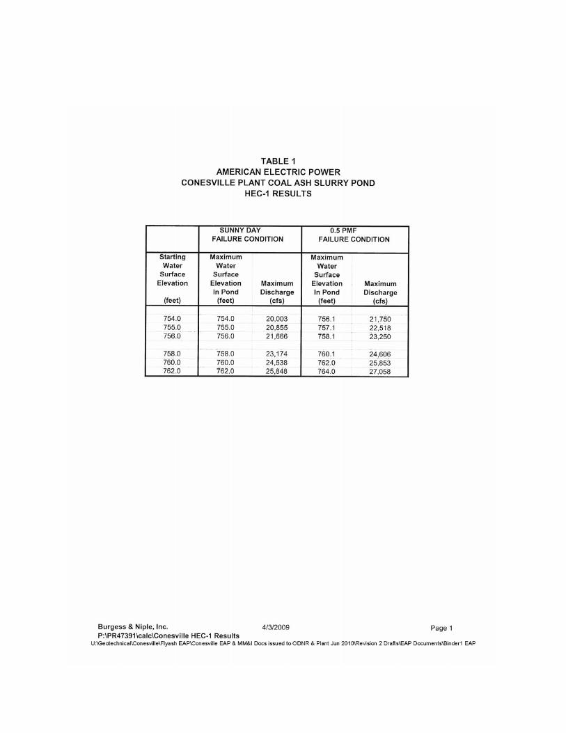
Table 1, attached, summarizes the HEC-1 hydrologic analyses for determining the outflow from
the dam during normal pool and 50% PMF conditions. The table provides the modeling results for
starting pond elevations of 754, 755, and 756 for possible embankment failures to the south, and starting
pond elevations of 758, 760, and 762 for possible embankment failures to the north.
A higher starting water surface elevation before the storm results in a higher maximum water
surface elevation in the pond and also a somewhat higher maximum discharge from the breached
embankment. For the 50% PMF condition, the maximum water surface elevation and maximum
discharge are both higher than what was obtained from the normal pool failure with the same starting
pond elevation – this is reasonable since there is additional water depth added to the pond from the
precipitation in the 50% PMF condition.
Table 2 presents the HEC-RAS summary for downstream flood elevations and peak
discharges. Table 2 also provides the model analysis results for starting pond elevations of 754, 755, and
756 for possible embankment failures to the south, and for starting pond elevations of 758, 760, and 762
for possible embankment failures to the north.
At locations downstream of the failed embankment either on the north or south sides, the flows at
each modeling cross section and the corresponding water surface elevations are all very similar. For
example, for the south embankment, normal pool failure condition, the water surface elevation for a
starting elevation of 756 is 734.07 at station 0.00 while for a starting elevation of 754 it is 733.55, a
difference of only 0.52 feet. Similarly, the 50% PMF water surface elevations are about 0.4 foot higher
than for the normal pool failure condition for the same starting water elevation in the pond. For the
accuracy of mapping that is available with existing 2-foot contours, these differences are nearly
indistinguishable.

ATTACHMENTS


TABLES


FLOOD INUNDATION MAPS


APPENDIX B
TRAINING, EXERCISING, UPDATING,
AND POSTING THE EAP

B-1
APPENDIX B
TRAINING, EXERCISING, UPDATING AND POSTING THE EAP A. Training
The Conesville Power Plant EAP Coordinator (Plant Environmental Coordinator) shall be thoroughly familiar with the Emergency Action Plan (EAP) and the actions that may be required under the EAP. The EAP Coordinator shall be responsible for:
1. Conducting orientation seminars for plant personnel who are involved in the
inspection and operations of the ash pond complex. The seminars will also include personnel who may respond to outside callers reporting an unusual condition at or near the ponds.
2. Conducting an initial coordination meeting with key plant personnel and
appropriate local and state agencies to review the EAP and discuss the responsibilities of each agency. Once the initial EAP has been presented and distributed to the authorities, annual face-to-face meetings shall be conducted with the authorities to review/update their copies of the EAP. If there are significant changes to the initial EAP, a coordination meeting with all the participants will be conducted.
3. Training alternate AEP staff to complete the Emergency Response Leader duties in the event the Team Leader is not available during a period of emergency as described in this EAP.
4. All attendees of such training sessions shall sign the EAP Training Record Form. B. Exercising The EAP Coordinator shall plan and convene an emergency exercise one time each year. The exercise shall include appropriate AEP administrative, operations, and maintenance personnel. Response organizations shall be invited to participate, however, their

B-2
unavailability shall not be cause for not completing the exercise. The exercise shall be performed to test the procedures and determine appropriate actions in the event of an emergency. At the conclusion of the exercise, the personnel shall review the exercise and prepare a written summary of lessons learned and items that can be improved upon. C. Updating the EAP The EAP Coordinator will be responsible for conducting an annual review of the Plan. The annual review shall include the following items: 1. AEP personnel names, positions, and/or phone numbers shall be verified and
revised as necessary. 2. All telephone numbers listed for external agencies shall be called and verified that
they are the correct numbers to dial in the event of an emergency. 3. Descriptions of alterations to the dam embankments and/or outlet structures. 4. Additions or deletions to the list of Emergency Supplies and Resources. Upon completion of each annual review, the EAP Coordinator shall complete the form on the following page to document the review and update. Revised pages shall be distributed to all EAP recipients with a summary of the changes. If there are no revisions necessary within a given year, the EAP Coordinator shall document that the Plan has been reviewed. A Professional Engineer shall review the EAP every 5 years to assure that it remains viable in the event that an emergency should occur at the dam. At a minimum, the Professional Engineer’s activities should include: • A site visit to inspect the dam and appurtenances and to review staffing and
emergency responses by AEP personnel • Review of the written plan

B-3
• Confirm that Emergency Supplies and Resources are current • Complete any necessary technical updates to the EAP. D. Posting of the Notification Flowchart An up-to-date copy of the Notification Flowcharts shall be posted in the control room and in the office of the Team Leader.
The EAP Coordinator shall maintain a minimum of one copy of the EAP at the Conesville Plant and a copy for AEP-Civil Engineering Department.
See Appendix D for the distribution list of the EAP and the number of full copies/sets of inundation maps each agency shall receive as updates. The EAP Coordinator shall be responsible for distribution of the EAP and any updates.

B-4
CONESVILLE GENERATING PLANT EMERGENCY ACTION PLAN TRAINING RECORD FORM
Use this form to record training sessions. File the completed form in the EAP. A thorough review of all items in the EAP should be discussed during training. Appropriate employees and EAP team members should attend the training session, annually or participate in a simulated exercise. TRAINING LOCATION: DATE: TIME: INSTRUCTOR: ________________________
CLASS SIGN-IN
Summary and Commentary:

B-5
CONESVILLE GENERATING PLANT
EMERGENCY ACTION PLAN PLAN REVIEW AND UPDATE RECORD
The EAP must be reviewed and updated (if necessary) annually for accuracy of information provided, particularly to keep contact names and telephone numbers up-to-date. At the conclusion of each review and update the changes shall be indicted in the following table.
Date Review Completed
Name and Title of Reviewer Changes Made

APPENDIX C
SITE-SPECIFIC DATA
APPENDIX C
SITE-SPECIFIC DATA STUDIES/DESIGN REPORTS All engineering studies and design reports related to the ash pond complex, including Appendix A - Dam Break Analysis, at the Conesville Power Plant are stored at the corporate offices of American Electric Power. These documents include design drawings and topographic mapping. Copies of most drawings are also available at the power plant. The power company will make discretionary availability of these documents. The following lists the contact and address for request of information. American Electric Power Manager – Geotechnical Engineering Section 1 Riverside Plaza Columbus, OH 43215 614-716-2917 Plant Manager Conesville Power Plant 42701 County Road 273 Conesville, Ohio 43811

APPENDIX C APPENDIX C
EMERGENCY SUPPLIERS OF MATERIALS Crushed Rock and Stone, Bottom Ash National Lime and Stone 740-622-6892 William Albert Excavating 740-622-3045
Diving Services AEP Diving Coordinator, Dustin Zirkly cell: 304-593-6137 / office: 304-675-8258
Fabricators and Machine Shop Services Muskingum Grinding 740-622-4741 Knowlton Steel 740-872-6100
Concrete & Patching Materials Smith Concrete 800-936-4937 Adams Brothers Concrete 740-452-7566
Contractors Headwaters 740-622-8001 Williams Albert Excavating 740-622-3045
Crane Service Capital City Crane 740-521-4646 William Albert Excavating 740-622-3045

SITE –SPECIFIC DATA CONT’D
Responsible Individuals (not listed on Notification Charts)
Office Phone # Team Leaders (Audinet) Office Phone # Cell # A. Miles Kimball 288-4886 740-829-4886 740-552-1179 B. Mark Grier 288-4042 740-829-4042 740-294-8992 C. Gene Whilett 288-4884 740-829-4884 740-502-4080 D. Mark Andrews 288-4882 740-829-4882 740-552-1019 Conesville Plant Personnel A. Coal Yard Staff: Tom Hammond 288-4109 740-829-4109 740-404-3624 Rich Rollison 288-3275 740-829-3275 740-404-1514

APPENDIX C
SITE-SPECIFIC DATA
LOCAL TV AND RADIO STATIONS
Station Name Location Phone Number A. WTNS Radio Coshocton 740-622-1560 B. WHIZ TV Zanesville 740-452-5431 C. D. E. F. Other Important Numbers A. Conesville Volunteer Fire Department 740-829-2385 B. State Emergency Response Commission (SERC) 740- 644-2260 C. State Police-Newport, Ohio 740- 374-6616 C. Local Emergency Planning Committee (LEPC) Muskingum County 740- 962-3183 Coshocton County 740- 373-5613 E. F. Weather Report Parkersburg, W. Va. 304- 422-4500 G. Hospitals: Coshocton Regional Medical 740-622-6411
Genisis Health Care Zanesville 740-454-4000 H. Ambulance Service: Coshocton County EMS 740-622-4294
Community Ambulance 740-454-6800
APPENDIX D
PREPARATION AND APPROVAL OF THE EAP


APPENDIX E
DISTRIBUTION LIST/ACKNOWLEDGEMENT

APPENDIX E
DISTRIBUTION LIST/ACKNOWLEDGEMENT The following are copies of Receipt Signature Pages indicating that each agency on the distribution list has received, read, and understood the Plan and agree to their responsibilities. The list below provides the name, address, and phone number and number of copies to which the Emergency Action Plan has been distributed.
Name/Address Copies Conesville Power Plant 6 42701 County Road 273 Conesville, Ohio 43811 AEP 1 Civil Engineering 1 Riverside Plaza Columbus, Ohio 43215 (614) 716-2917 Coshocton County Emergency Planning Committee 2 Police Department 1 County Sheriff 1

Name/Address Copies Division of Water Resources, Dam Safety Program 1 Ohio Department of Natural Resources Fountain Square, Bldg., B-3 Columbus, Ohio 43224 (614) 265-6731 Coshocton County Sheriff 1

AMERICAN ELECTRIC POWER CONESVILLE POWER PLANT
ASH POND COMPLEX
EMERGENCY ACTION PLAN RECEIPT SIGNATURE PAGE
This is to acknowledge receipt of the appropriate number of copies of the Emergency Action Plan for the Ash Pond Complex at the Conesville Power Plant. We have read and understood the Plan and agree to our responsibilities listed in the Plan. NAME (Print)_________________________________________________ SIGNATURE__________________________________________________ DATE________________________________________________________ AGENCY/COMPANY __________________________________________ Please return to: Conesville Power Plant 42701 County Road 273 Conesville, Ohio 43811 Attn: EAP Coordinator