Numerical optimisation methods applied to the concurrent ...
Upload
vinay-jokareCategory
view
45download
0description

WHITEPAPER:
Concurrent CFD Analysis Methods Boost Automotive Design Productivity
A Strategic Engineering Tool for the Automotive Industry

_________________________________________________________________________ Mentor Graphics: Accelerate Automotive Design with FloEFD 2
Abstract
A new class of Computational Fluid Dynamics (CFD) analysis software, ‘Concurrent CFD’, is
proving to be highly effective at performing heat, fluid and airflow analyses, enabling Engineers to
accelerate key decisions at their workstations and without the need for CFD specialists. This
intuitive MCAD embedded process allows designers to optimize a product during the design stages
reducing manufacturing costs across a wide range of automotive parts and systems such as
heating, cooling, fuel delivery systems, braking systems, exhaust systems, body panels etc, etc.
Traditional and up-front CFD approaches have either been difficult, cumbersome or time
consuming in their use, but with Concurrent CFD, mechanical design teams can accelerate the
design process, increase their productivity workflow, reduce re-spins and increase profits. This
paper includes two case studies using Mentor Graphics Concurrent CFD technology for automotive
design applications.

_________________________________________________________________________ Mentor Graphics: Accelerate Automotive Design with FloEFD 3
It’s now common knowledge that
computer modeling/virtual prototyping in
the form of Computational Fluid
Dynamics (CFD) can make major
contributions in reducing product costs
and accelerating time to market.
However, many managers fail to realize
that the latest software advances are now
making these benefits both accessible and affordable to small- and mid-sized enterprises. This is
in part thanks to a new design/analysis technology known as ‘Concurrent CFD’, created by leading
simulation software company Mentor Graphics. Aimed specifically at the mechanical design
engineer, Mentor Graphics have introduced FloEFD, a Concurrent CFD software that is embedded
– concurrent, in a users MCAD system. With it there is no longer the need to hire or train CFD
specialists, outsource analysis to consultants, or conduct tests on expensive multiple physical
prototypes; instead, a design engineer - with standard training and working in any size company,
can use their existing knowledge to successfully perform flow and heat transfer analyses all within
their already familiar MCAD environment, helping increase workflow and dramatically reducing the
number of physical prototypes needed.
This breakthrough arose because FloEFD is able to simplify the process of setting up and running
a flow or heat transfer analysis. Certainly, there will always be a few very demanding applications
where a more advanced CFD knowledge is needed to fine-tune the meshing and solver settings in
order to converge to a solution. However, experience shows that using their existing knowledge,
design engineers with no specific training in CFD codes can correctly perform an analysis in
roughly 80% to 90% of the situations they encounter. This ability to take CFD out of the exclusive
domain of specialists and bring it into the mainstream represents a fundamental change in the
design process. Just as the shift from 2D to 3D CAD required a mental leap, so does FloEFD –
and the results are perhaps even more significant.
Because of these factors, the scope of applications for
CFD is expanding tremendously. Although many
managers in the automotive industry might think that
flow analysis is dedicated to studying the
aerodynamics of a vehicle’s exterior, this is only the
start of where FloEFD can be applied. Another
application that might come to mind is the study of
flow through a valve in order to size it or the air flow
through ventilation ducting to control cabin comfort temperatures. However, FloEFD is actually
being used to optimize the design and manufacture of a wide variety of parts such as pumps,
Using their existing knowledge, design
engineers with no specific training in CFD codes can
correctly perform an analysis in roughly 80% to 90% of the situations they
encounter.
_________________________________________________________________________ Mentor Graphics: Accelerate Automotive Design with FloEFD 4
braking systems, filters, fuel cells, manifolds, lights, transmissions and a multitude of other
components both mechanical and electrical. It is also important to note that fluid-flow effects
inevitably have a result on the movement of heat from a device or process and FloEFD is equally
good at studying these heating effects in components and systems of all sizes.
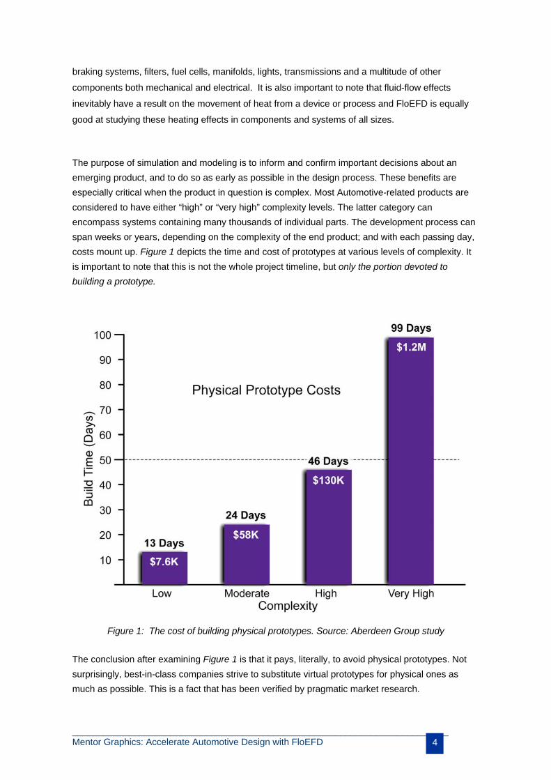
The purpose of simulation and modeling is to inform and confirm important decisions about an
emerging product, and to do so as early as possible in the design process. These benefits are
especially critical when the product in question is complex. Most Automotive-related products are
considered to have either “high” or “very high” complexity levels. The latter category can
encompass systems containing many thousands of individual parts. The development process can
span weeks or years, depending on the complexity of the end product; and with each passing day,
costs mount up. Figure 1 depicts the time and cost of prototypes at various levels of complexity. It
is important to note that this is not the whole project timeline, but only the portion devoted to
building a prototype.
The conclusion after examining Figure 1 is that it pays, literally, to avoid physical prototypes. Not
surprisingly, best-in-class companies strive to substitute virtual prototypes for physical ones as
much as possible. This is a fact that has been verified by pragmatic market research.
Figure 1: The cost of building physical prototypes. Source: Aberdeen Group study
_________________________________________________________________________ Mentor Graphics: Accelerate Automotive Design with FloEFD 5
Potential savings in the millions for just one project
The bottom line for procurement of any hardware or software for an engineering team is: Can it
save us time, can it save us money? FloEFD packages which cost in the range of $20,000 to
$30,000 for a perpetual license, can generally pay for themselves in the first project in which they
are used – with the benefits continuing on for years.
Convincing proof of this claim comes from a study conducted by the Aberdeen Group
(“Engineering Decision Support: Driving Better Product Decisions and Speed to Market”). The
study first compares 190 companies by means of several key performance criteria related to
meeting cost/revenue targets and hitting product-launch dates; it then categorizes the
organizations it studied into three groups: “best-in-class”, “industry average” and “laggards”.
Time and Cost Saved with 1.1 Fewer Prototypes
Source: Aberdeen Group, 2007
Table 1: A study by the Aberdeen Group shows that even with 1.1 fewer physical prototypes - made possible
by the use of virtual prototypes in software, the savings in both time and money are considerable.
Not surprisingly, the strategy adopted by best-in-class companies is to trade physical prototypes for
virtual ones as much as possible. These top companies conduct a mean number of 7.3 virtual iterations
whereas laggards perform only 2.8. The obvious consequence is that with fewer virtual prototypes, the
laggards need more physical prototypes: a mean of 3.8 for laggards compared to only 2.7 for best-in-
class organizations – 1.1 fewer physical prototypes. The savings accrued in these 1.1 fewer physical
prototypes can be enormous (see Table 1): For a product of low complexity, a cost savings
approaching $10,000; for a product of very high complexity, the savings are well over a million dollars!
Financial benefits also span the product’s useful lifetime. As stated by the AUTOSIM Consortium (a
project funded by the European Commission), a product that is six months late to market, even if on
budget, will generate an average of 33% less revenue during a 5-year period than it would if introduced
Product
Complexity
Number of
Parts
Length of
Development
Time Saved
(days)
Cost Saved ($)
Low <50 1 week – 1 year 14 $8,360
Moderate 50 – 1000 1 month –
5 years
26 $63,800
High 50 – 10,000 1 – 5 years 51 $143,000
Very High 1000 – 100,000 1 – 20 years 109 $1,320,000

_________________________________________________________________________ Mentor Graphics: Accelerate Automotive Design with FloEFD 6
on time and, as Figure 1 shows, having just one fewer physical prototypes can eliminate anything from
14 to 100 days from the project development timeline.
The key message today is that these time and cost
savings are now available to virtually every design
engineering team.
Awardwinning
FloEFD moves CFD into the mainstream
Although the computer modeling of engineering
systems is now available to every engineering team,
the underlying concept is nothing new. For
centuries, scientists have used mathematical
models to describe the world around us. Newton
and Leibnitz independently developed differential
calculus to allow them to add dynamics to models.
In fact, with a relatively simple model, Newton was
able to predict planetary orbits. This feat was so
revolutionary that it even challenged the then
current view of the universe.
In the following decades and centuries, researchers discovered the formulas that describe various
physical phenomena whether mechanical, structural, chemical or across the entire electromagnetic
spectrum. For the flow of a liquid or gas, the most basic relationships are the Navier-Stokes equations,
which were initially developed in the early 1800s. Their use was limited though, because realistic
problems became so complex that it was impossible to find an analytical solution and it became
necessary to find solutions using the brute force of approximate numerical methods – bringing what we
now know as Computational Fluid Dynamics.
Only with the emergence of computers in the 1950s did CFD studies start to become feasible, but they
were based on programs - also known as “codes”, developed and written by researchers, usually in
academia or government-sponsored programs. These codes were custom programmed for each
individual case. Only in the 1980’s did commercial codes become available to bring CFD to a wider
audience, but they also required specialists who could understand how to properly set up the software
such as getting a good mesh and then selecting the best solvers and tuning their results. Even so, with
such packages, engineers were able to model any flow field if they could define the geometry, identify
the underlying physics and prescribe some initial conditions.
The skills required to operate
FloEFD software are simply
knowledge of the CAD system and
the physics of the product, both of
which the vast majority of design
engineers already possess.
Engine water-cooling jacket
_________________________________________________________________________ Mentor Graphics: Accelerate Automotive Design with FloEFD 7
These early adopters started to solve a wide variety of problems with commercial CFD codes, and
providers of such software have used the past decade to refine the underlying meshers and solution
engines. The next step, taking place now, is to leverage these advances to achieve a breakthrough just
as significant as the introduction of the first commercial codes; the emergence of Mentor Graphics
Concurrent CFD technology and its software FloEFD.
FloEFD software was designed for use by everyday design engineers, not just specialists. It removes
all the barriers to the mainstream use of CFD. Until now, the greatest obstacle has been that traditional
CFD codes require users to have a deep understanding of the computational aspects of fluid dynamics
in order to obtain accurate results. In contrast, FloEFD’s groundbreaking features – its use of native 3D
CAD data, automatic definition of the flow space and the creation of a computational mesh for it, and the
management of flow parameters as object-based features – handled via a convenient wizard interface
eliminate the need for engineers to understand the computational side of CFD. Instead, they can focus
on the fluid dynamics of the product, an aspect that is already part of their responsibility and for which
they are trained and experienced. The skills required to operate FloEFD software are simply knowledge
of the CAD system and the physics of the product, both of which the vast majority of design engineers
already possess.
One major aspect that differentiates FloEFD is that it can be either fully embedded or at least tightly
integrated with most mechanical CAD packages engineers are familiar with.
After installation of the software, all the menus and commands necessary to run a full CFD flow or heat
analysis are created in the CAD packages menu system. This close interaction between the CAD and CFD
functions within FLOEFD - see Figure 2, brings with it several major benefits:
Engineers no longer have to export a file from their CAD environment into an analysis package or
spend time making the geometry “CFD-ready”, a process that can take hours, sometimes days.
Instead, FloEFD uses the same geometry the engineers have created in their mechanical CAD
package; any modifications to the CAD
geometry are carried over automatically to
the analysis.
Automatically detects the fluid regions of
interest; this contrasts to conventional CFD
software, which requires users to define the
computational domain of interest.
Transparently sets up and runs the mesher
and solver. CFD software, to be all things

_________________________________________________________________________ Mentor Graphics: Accelerate Automotive Design with FloEFD 8
to all people, offers a wide range of choices, most of which are never needed whereas FloEFD
software automatically chooses the appropriate solver and sets it up to find the solution.
Engineers do not have to worry about identifying when or where flow characteristics change
because FloEFD fully supports laminar, transition and turbulent flow.
It’s only necessary to set up the boundary conditions once; because of the unified environment,
these parameters remain fixed to the geometry unless the engineer chooses to modify them.
FloEFD also accelerates the iterative design process; engineers can quickly and easily incorporate
knowledge gained in an analysis into an improved design. With traditional CFD software, after
each geometrical change it is necessary to re-create the mesh which usually involves time-
consuming manual intervention. In contrast, FloEFD software operates immediately on the
changed geometry; creates a new mesh automatically, and works with the previously defined
boundary conditions. Thus, the step from a changed geometry to running the solver and
examining results is greatly accelerated.
The overall result is a much faster workflow with FloEFD that because of the tight integration of CAD and
CFD functions, eliminates the need to perform several steps in subsequent analysis runs.
Exhaust Manifold
Flow analysis of an intake manifold being performed within Pro/ENGINEER Wildfire – changes to the physical design are immediately available to the FloEFD software for analysis purposes.

_________________________________________________________________________ Mentor Graphics: Accelerate Automotive Design with FloEFD 9
With FloEFD, manufacturers can apply simulation at the concept stage so they can explore
design alternatives, detect design flaws, and optimize product performance before detailed
designs or physical prototypes are created. FloEFD also makes it easy to conduct “what-if”
analysis. Engineers can modify the solid model without having to re-apply loads, boundary
conditions and material properties. The software also aids in parametric analysis, for example,
running an analysis multiple times with various wall thicknesses in a valve to determine the
optimal thickness.
A multitude of applications
Until recently, a common thought among managers was, “I don’t see how FloEFD can help my
staff design their products better. After all, fluid flow isn’t a major factor in our designs.”
Meanwhile, best-in-class suppliers have discovered the enormous benefits of FloEFD go far
beyond traditional applications such as aerodynamics.
In the automobile industry alone, engineers use FloEFD software for optimizing the following
products and processes; Pressure drop in fuel injectors, heat transfer in radiators, fluid flow in
catalytic converters, exhaust and emission control systems, and:-
Under-hood airflow and thermal management
Passenger comfort and environmental control systems
Coolant flow in water jackets, engine blocks and cylinder heads
Cooling of electronic systems, braking systems, powertrain components, headlamps etc.
Performance of heat exchangers and heat sinks
Flow and pressure drop through filters
Fuel cell performance
Hydraulic systems
Vehicle Ventilation Vehicle Turbo
_________________________________________________________________________ Mentor Graphics: Accelerate Automotive Design with FloEFD 10
Aerodynamics of whole vehicles or components such as wing mirrors, windscreen wipers,
spoilers, etc.
It becomes clear that FloEFD can prove invaluable in many other industries beyond vehicle
manufacturing. In fact, there are very few industries or product areas that cannot benefit from
Mentor Graphics Concurrent CFD software!
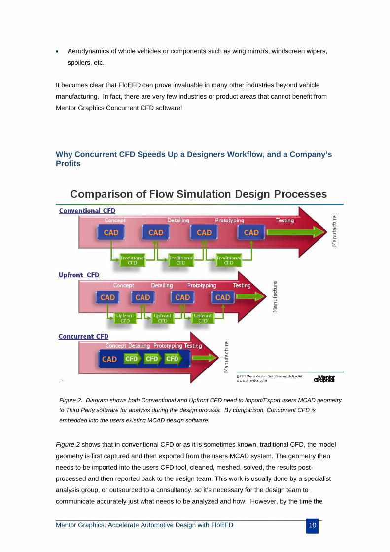
Why Concurrent CFD Speeds Up a Designers Workflow, and a Company’s Profits
Figure 2 shows that in conventional CFD or as it is sometimes known, traditional CFD, the model
geometry is first captured and then exported from the users MCAD system. The geometry then
needs to be imported into the users CFD tool, cleaned, meshed, solved, the results post-
processed and then reported back to the design team. This work is usually done by a specialist
analysis group, or outsourced to a consultancy, so it’s necessary for the design team to
communicate accurately just what needs to be analyzed and how. However, by the time the
Figure 2. Diagram shows both Conventional and Upfront CFD need to Import/Export users MCAD geometry
to Third Party software for analysis during the design process. By comparison, Concurrent CFD is
embedded into the users existing MCAD design software.
_________________________________________________________________________ Mentor Graphics: Accelerate Automotive Design with FloEFD 11
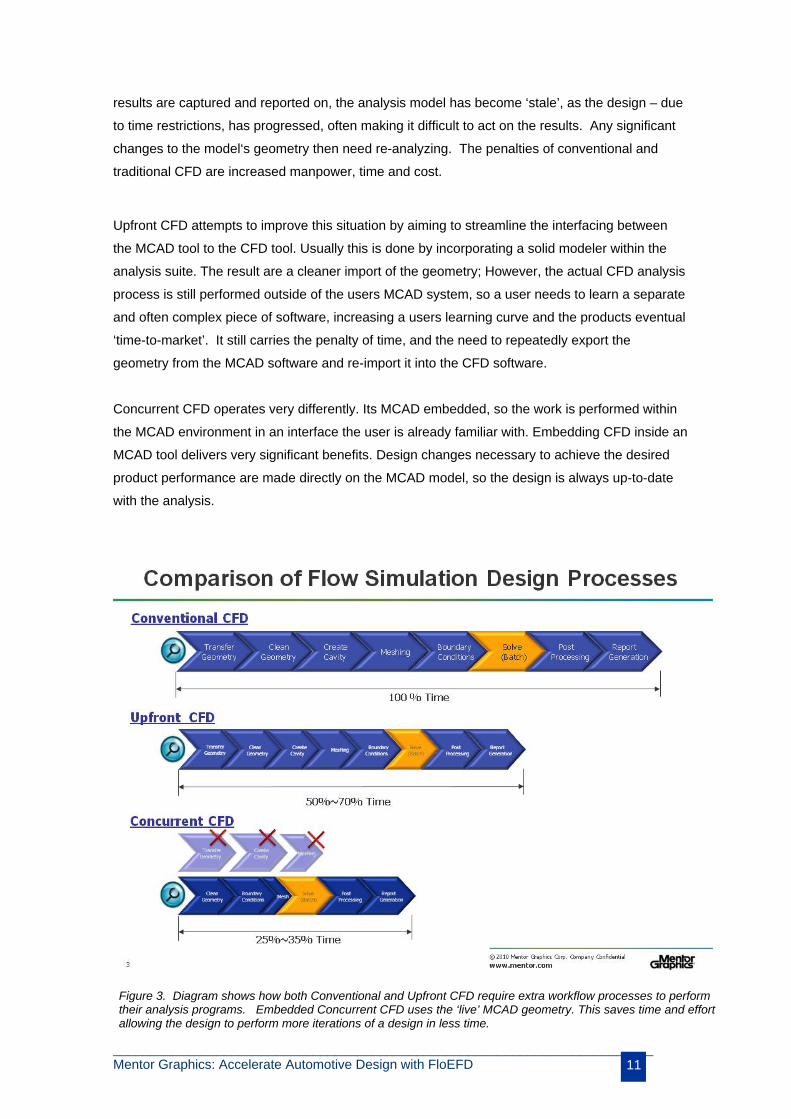
results are captured and reported on, the analysis model has become ‘stale’, as the design – due
to time restrictions, has progressed, often making it difficult to act on the results. Any significant
changes to the model‘s geometry then need re-analyzing. The penalties of conventional and
traditional CFD are increased manpower, time and cost.
Upfront CFD attempts to improve this situation by aiming to streamline the interfacing between
the MCAD tool to the CFD tool. Usually this is done by incorporating a solid modeler within the
analysis suite. The result are a cleaner import of the geometry; However, the actual CFD analysis
process is still performed outside of the users MCAD system, so a user needs to learn a separate
and often complex piece of software, increasing a users learning curve and the products eventual
‘time-to-market’. It still carries the penalty of time, and the need to repeatedly export the
geometry from the MCAD software and re-import it into the CFD software.
Concurrent CFD operates very differently. Its MCAD embedded, so the work is performed within
the MCAD environment in an interface the user is already familiar with. Embedding CFD inside an
MCAD tool delivers very significant benefits. Design changes necessary to achieve the desired
product performance are made directly on the MCAD model, so the design is always up-to-date
with the analysis.
Figure 3. Diagram shows how both Conventional and Upfront CFD require extra workflow processes to perform their analysis programs. Embedded Concurrent CFD uses the ‘live’ MCAD geometry. This saves time and effort allowing the design to perform more iterations of a design in less time.

_________________________________________________________________________ Mentor Graphics: Accelerate Automotive Design with FloEFD 12
In Figure 3 it becomes apparent why concurrent CFD is different to conventional and upfront
CFD. By expanding the CFD workflow procedures, we can see they involve a number of process
steps to obtain a full analysis report on a design. Both conventional and upfront CFD require
geometry transferring from the MCAD system and cleaning it up so it’s suitable for analysis. This
process has to be repeated each time a design change occurs, to keep the MCAD geometry and
CFD analysis synchronized. Typically this approach will require the geometry’s fluid spaces to be
‘watertight’ for the analysis. In MCAD terms this is referred to as ‘healing’ the geometry to make it
‘manifold’, whereas analysts often refer to it as ‘cleaning the MCAD model’. This is a generic
requirement for CFD analysis, so it appears in all three approaches. Another process in both
conventional and upfront CFD is the “Create Cavity” step. Most conventional CFD meshing tools
work by meshing a solid, so they require a solid object to mesh. For a CFD simulation the solid
object is the flow space, which – for conventional and upfront CFD tools has to be created as a
dummy part within the MCAD system by Boolean subtraction of the entire model from an
encapsulating solid. This is usually done in the MCAD system and it’s this inverted flow space
that is transferred to the external third party CFD software for meshing and analysis.
By comparison, MCAD embedded concurrent CFD works rather differently. The geometry used
for the analysis is native to the MCAD system. This means that there is no geometry transfer step
because the designer never has to leave his/her MCAD software. Concurrent CFD therefore
eliminates the “transfer geometry” and “create cavity” steps, and effectively meshes in one step.
Meshing still takes place, but only takes minutes rather than hours of iterating back and forth.
This speeds up a user’s workflow, allowing them time to explore ‘what if’ optimization changes
which could enhance still further a designs reliability and overall manufacturing costs.
Concurrent CFD provides one final benefit that’s not shown in the diagram. As mechanical
designers undertake their own analyses they quickly learn how to build analysis-friendly geometry
within their MCAD software, further eliminating the “clean geometry” step, so the time savings can
be even greater than those indicated!
_________________________________________________________________________ Mentor Graphics: Accelerate Automotive Design with FloEFD 13
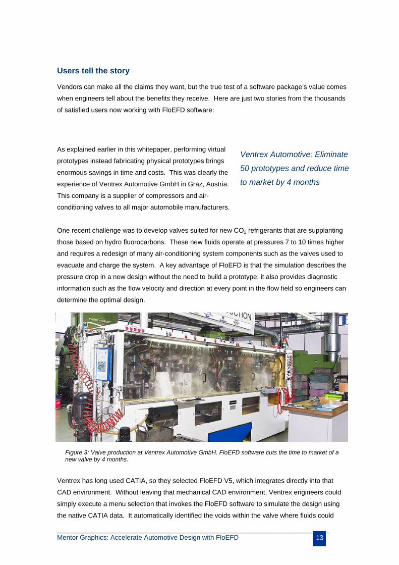
Users tell the story Vendors can make all the claims they want, but the true test of a software package’s value comes
when engineers tell about the benefits they receive. Here are just two stories from the thousands
of satisfied users now working with FloEFD software:
As explained earlier in this whitepaper, performing virtual
prototypes instead fabricating physical prototypes brings
enormous savings in time and costs. This was clearly the
experience of Ventrex Automotive GmbH in Graz, Austria.
This company is a supplier of compressors and air-
conditioning valves to all major automobile manufacturers.
One recent challenge was to develop valves suited for new CO2 refrigerants that are supplanting
those based on hydro fluorocarbons. These new fluids operate at pressures 7 to 10 times higher
and requires a redesign of many air-conditioning system components such as the valves used to
evacuate and charge the system. A key advantage of FloEFD is that the simulation describes the
pressure drop in a new design without the need to build a prototype; it also provides diagnostic
information such as the flow velocity and direction at every point in the flow field so engineers can
determine the optimal design.
Ventrex has long used CATIA, so they selected FloEFD V5, which integrates directly into that
CAD environment. Without leaving that mechanical CAD environment, Ventrex engineers could
simply execute a menu selection that invokes the FloEFD software to simulate the design using
the native CATIA data. It automatically identified the voids within the valve where fluids could
Ventrex Automotive: Eliminate
50 prototypes and reduce time
to market by 4 months
Figure 3: Valve production at Ventrex Automotive GmbH. FloEFD software cuts the time to market of a new valve by 4 months.
_________________________________________________________________________ Mentor Graphics: Accelerate Automotive Design with FloEFD 14
flow, and the engineers simply had to specify the boundary conditions, in this case the inlet and
outlet pressures. “Within a few hours we had a complete simulation of the initial concept design
and were able to turn our attention to improving it,” says the firm’s project manager.
The result? “CAD-embedded CFD makes it possible to determine simulation results nearly as
fast as we can change the design. We were able to improve the flow rate of our new CO2 valve
by 15% while eliminating roughly 50 prototypes and reducing time to market by 4 months.”
Miniature Precision Components: Quickly evaluate 12 design alternatives A recognized leader in the innovative design and production of world-class thermoplastic parts for
the automotive and commercial industries, Miniature Precision Components (MPC) supplies
functional thermoplastic injection, extrusion, and suction blow molded assemblies/subassemblies.
Headquartered in Walworth, Wisconsin, USA, the company has roughly 1500 employees.
As an interim step towards a long-term mandate for zero-emission vehicles, which will require the
production of vehicles driven by electricity or hydrogen fuel cells, several states in the USA allow
the licensing of partial zero-emission vehicles (PZEVs) that continue to use gasoline engines. In
order to qualify as a PZEV, a vehicle must meet the “super ultra low emission vehicle” standard
and have zero evaporative emissions from its fuel system. A key feature of a PZEV vehicle is a
hydrocarbon trap in the air intake that prevents stray hydrocarbons from migrating out of the
engine after shutdown -- but it must do so while avoiding a significant increase in backpressure
for air entering the engine because that would adversely affect fuel efficiency and performance.
In designing a cost-competitive hydrocarbon trap, engineers at MPC started by creating the
physical design as a CATIA model. They started by analyzing various rib configurations based
on experience. Doing so with FloEFD V5 software was easy because they simply defined the
boundary conditions and ran a flow analysis. They soon found that a 5-spoke version’s
backpressure was the lowest, but it was not low enough. The engineers then ran through roughly
a dozen iterations of the 5-spoke design, each time changing the spokes’ geometry and the
spacing of the carbon elements. Says the engineer in charge of this project, “By the end of this
process, I had beaten the target for backpressure, at least in the software. We built a rapid
prototype and found that its backpressure was within 0.1 in. of water of the CFD predictions.”
_________________________________________________________________________ Mentor Graphics: Accelerate Automotive Design with FloEFD 15
An easy step to dramatically higher productivity
FloEFD can make a large contribution to your efforts to reduce costs and speed time to market,
all while optimizing product design and thus customer satisfaction. The investment in the
software will most likely pay for itself in the first project:-
1. Because the software is embedded into the CAD system your engineers are already
familiar with
2. Because it is so intuitive to use, there is a very small short learning curve – engineers can
be productive with FloEFD software in a matter of hours.
If you are working with any of the following 3D CAD packages, which together dominate the
automotive market, we offer an integrated FloEFD solution that you can put to use immediately:
FloEFD V5: For CATIA V5
FloEFD Pro: For Pro/ENGINEER Wildfire
FloEFD: Here you import the CAD model into the FloEFD 3D environment and
immediately gain all the features and functionality of the FloEFD design and analysis
process. for virtually all other CAD package including:
Autodesk Inventor
Siemens NX
Solid Edge
CoCreate
SpaceClaim
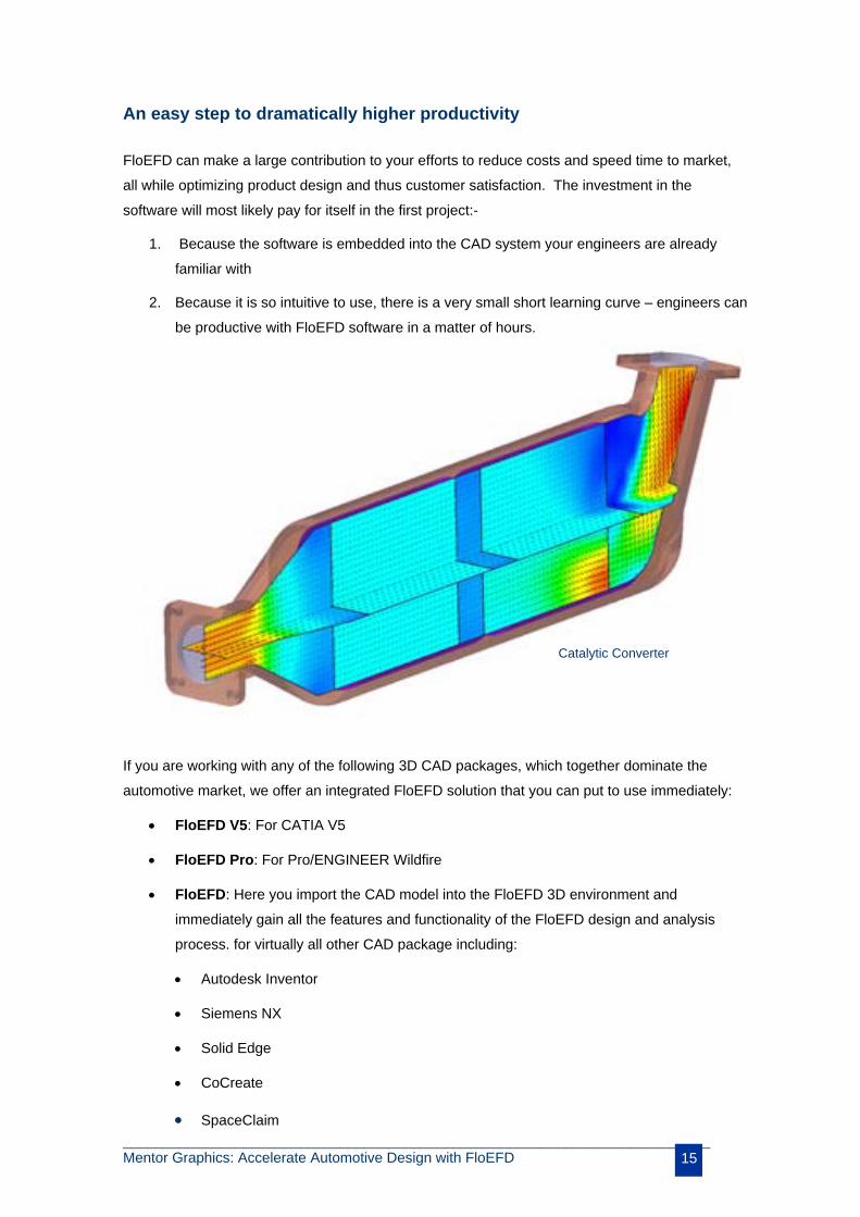
Catalytic Converter

_________________________________________________________________________ Mentor Graphics: Accelerate Automotive Design with FloEFD 16
For detailed information…
Minimal investment, maximal gain: If your company isn’t already using FloEFD software, you
should be. Speak with your design team and encourage them to get in touch with us – we’ll
be happy to explain how they can get on board with this exciting new technology quickly and
easily.
For additional information, please contact:
Mentor Graphics Corp
Mechanical Analysis Division
81 Bridge Road Hampton Court Surrey KT8 9HH UK
Tel: +44 (0)20 8487 3000
Fax: +44 (0)20 8487 3001
Mentor Graphics Corp
300 Nickerson Road, Suite 200 Marlborough Massachusetts 01752 US
Tel: +1 (508) 480 0881
Fax: +1 (508) 480 0882
©2008 Mentor Graphics Corp. All rights reserved. All products mentioned are trademarks or trade names of their respective companies.