Concrete Tech Guide
132
Bouygues bâtiment International – Engineering division – BES BA Practical Guide : The concrete on the international market PRACTICAL GUIDELINES CONCRETE ON INTERNATIONAL MARKET Author: Camille d’Arnoux Supervisor : Marc Blondeau 2007
-
Upload
havinhphuc -
Category
Documents
-
view
405 -
download
4
Transcript of Concrete Tech Guide

Bouygues bâtiment International – Engineering division – BES BA Practical Guide : The concrete on the international market
PRACTICAL GUIDELINESCONCRETE ON INTERNATIONAL
MARKET
Author: Camille d’ArnouxSupervisor : Marc Blondeau2007

Bouygues bâtiment International – Engineering division – BES BA Practical Guide : The concrete on the international market
Pathway to determine a suitable concrete for a construction
In order to create a durable construction, you must:-use a durable material
-design the structure according to environmental factors-carry out proper checks on the quality of the materials and on construction techniques
Normative / contractual
restraints
Materials and concrete
ProcessPlacing /
Special concretes
Specificcharacteristics ofthe construction
Pathology/ Risk Prevention
Surroundingsand exposure ofthe construction
Normative constraints
AggregatesDaily
requirements
Special concretes
HeightGeographical
zone
Contractual constraints
CementCapacity of
the mixing plant
Standard method forplacing concrete
Length ofspans
Immediatesurroundings
Particular methods of placing
Admixture SurroundingsDistance between
jointsGround / Water
table
Mixing waterSite mixing plant
/ Ready mixLarge units Particular
conditions for use
ConcreteAttractive
appearanceLife period
Architecturaldesign
Checks
Bouygues bâtiment International – Engineering division – BES BA Practical Guide : The concrete on the international market
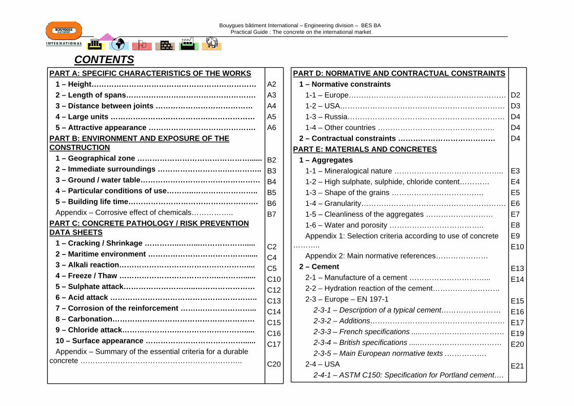
PART A: SPECIFIC CHARACTERISTICS OF THE WORKS1 – Height…………………………………………………………2 – Length of spans…………………………………………….3 – Distance between joints …………………………………4 – Large units ………………………………….………………5 – Attractive appearance …………………………………….
PART B: ENVIRONMENT AND EXPOSURE OF THE CONSTRUCTION
1 – Geographical zone ………………………………………......2 – Immediate surroundings ……………………….…………..3 – Ground / water table…………………………………………4 – Particular conditions of use………..……………………..5 – Building life time…………………………………………….Appendix – Corrosive effect of chemicals……………..
PART C: CONCRETE PATHOLOGY / RISK PREVENTION DATA SHEETS
1 – Cracking / Shrinkage …………..……...……………….....2 – Maritime environment …………………………………......3 – Alkali reaction……………………………………………....4 – Freeze / Thaw …………………………………..………......5 – Sulphate attack………………………..……………………6 – Acid attack …………………………………………………..7 – Corrosion of the reinforcement …….…………………...8 – Carbonation…………………………………………………9 – Chloride attack………………….……………………….....10 – Surface appearance …………………………………......Appendix – Summary of the essential criteria for a durable
concrete ………………………………………………………..
A2A3A4A5A6
B2B3B4B5B6B7
C2C4C5C10C12C13C14C15C16C17
C20
PART D: NORMATIVE AND CONTRACTUAL CONSTRAINTS1 – Normative constraints
1-1 – Europe………………………………………………………1-2 – USA…………………………………………………………1-3 – Russia………………………………………………………1-4 – Other countries ………………………………………..
2 – Contractual constraints …………………………………PART E: MATERIALS AND CONCRETES
1 – Aggregates1-1 – Mineralogical nature ……………………………………..1-2 – High sulphate, sulphide, chloride content…………1-3 – Shape of the grains ……………………………….1-4 – Granularity………………………………………………….1-5 – Cleanliness of the aggregates ………………………1-6 – Water and porosity ………………………………..Appendix 1: Selection criteria according to use of concrete
………..Appendix 2: Main normative references…………………
2 – Cement2-1 – Manufacture of a cement …………………………...2-2 – Hydration reaction of the cement………………………2-3 – Europe – EN 197-1
2-3-1 – Description of a typical cement……………………2-3-2 – Additions………………………………………………2-3-3 – French specifications .....……………………………2-3-4 – British specifications .....……………………………2-3-5 – Main European normative texts .…………….
2-4 – USA 2-4-1 – ASTM C150: Specification for Portland cement….
D2D3D4D4D4
E3E4E5E6E7E8E9E10
E13E14
E15E16E17E19E20
E21
CONTENTS
Bouygues bâtiment International – Engineering division – BES BA Practical Guide : The concrete on the international market
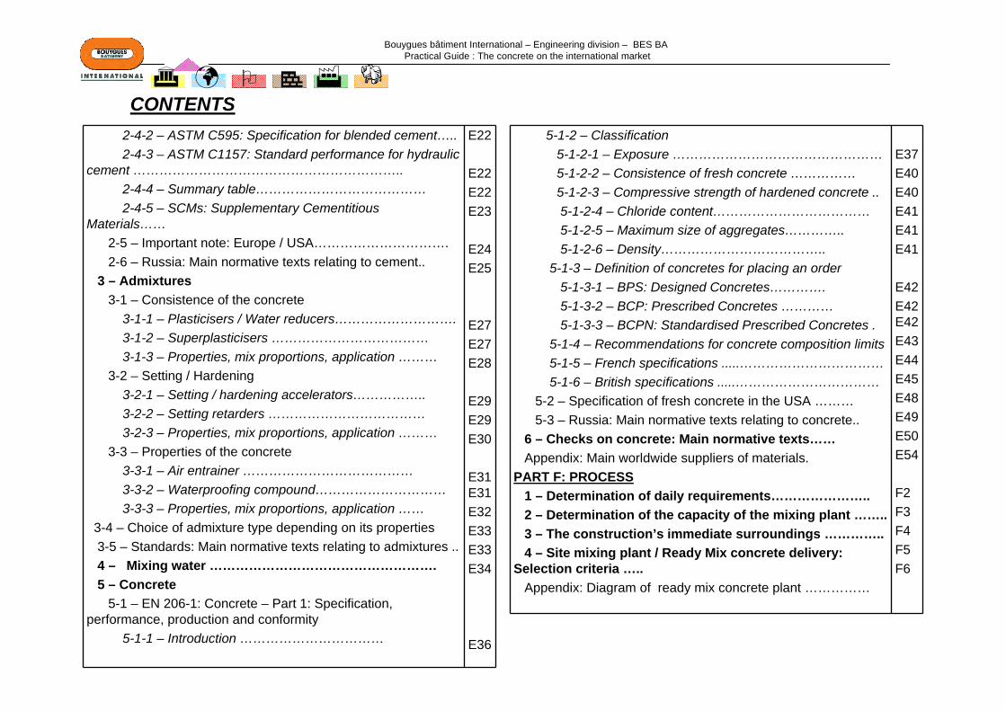
2-4-2 – ASTM C595: Specification for blended cement….. 2-4-3 – ASTM C1157: Standard performance for hydraulic
cement ……………………………………………………..2-4-4 – Summary table…………………………………2-4-5 – SCMs: Supplementary Cementitious
Materials……2-5 – Important note: Europe / USA………………………….2-6 – Russia: Main normative texts relating to cement..
3 – Admixtures3-1 – Consistence of the concrete
3-1-1 – Plasticisers / Water reducers……………………….3-1-2 – Superplasticisers ………………………………3-1-3 – Properties, mix proportions, application ………
3-2 – Setting / Hardening3-2-1 – Setting / hardening accelerators……………..3-2-2 – Setting retarders ………………………………3-2-3 – Properties, mix proportions, application ………
3-3 – Properties of the concrete 3-3-1 – Air entrainer …………………………………3-3-2 – Waterproofing compound…………………………3-3-3 – Properties, mix proportions, application ……
3-4 – Choice of admixture type depending on its properties 3-5 – Standards: Main normative texts relating to admixtures ..4 – Mixing water …………………………………………….5 – Concrete
5-1 – EN 206-1: Concrete – Part 1: Specification, performance, production and conformity
5-1-1 – Introduction ……………………………
E22
E22E22E23
E24E25
E27E27E28
E29E29E30
E31E31E32E33E33E34
E36
5-1-2 – Classification5-1-2-1 – Exposure …………………………………………5-1-2-2 – Consistence of fresh concrete ……………5-1-2-3 – Compressive strength of hardened concrete ..5-1-2-4 – Chloride content………………………………5-1-2-5 – Maximum size of aggregates…………..5-1-2-6 – Density………………………………..
5-1-3 – Definition of concretes for placing an order5-1-3-1 – BPS: Designed Concretes………….5-1-3-2 – BCP: Prescribed Concretes …………5-1-3-3 – BCPN: Standardised Prescribed Concretes .
5-1-4 – Recommendations for concrete composition limits5-1-5 – French specifications .....……………………………5-1-6 – British specifications .....……………………………
5-2 – Specification of fresh concrete in the USA ………5-3 – Russia: Main normative texts relating to concrete..
6 – Checks on concrete: Main normative texts……Appendix: Main worldwide suppliers of materials.
PART F: PROCESS1 – Determination of daily requirements…………………..2 – Determination of the capacity of the mixing plant ……..3 – The construction’s immediate surroundings …………..4 – Site mixing plant / Ready Mix concrete delivery:
Selection criteria …..Appendix: Diagram of ready mix concrete plant ……………
E37E40E40E41E41E41
E42E42E42E43E44E45E48E49E50E54
F2F3F4F5F6
CONTENTS

Bouygues bâtiment International – Engineering division – BES BA Practical Guide : The concrete on the international market
PART G: PLACING AND SPECIAL CONCRETES1 – General placing of concrete1-1 – Formwork ………………………………………….1-2 – Transport……………………………………………………1-3 – Vibration of the concrete ……………………………1-4 – Curing of the concrete ……………………………1-5 – Formwork removal ……………………………………. 1-6 – Daywork joints …………………………………….
2 – Special concretes2-1 – Compact and low permeability concrete ……2-2 – BHP: High-performance concretes…………………..2-3 – BAP: Self-placing concretes ………………………..2-4 – Fibre concretes ……………………………………….2-5 – Architectonic Concrete …………………………………2-6 – Lightweight and dense concretes …………………..2-7 – Pumped concretes ……………………………………. 2-8 – Other special concretes………………………………..
3 – Architectural design…………………………………. 4 – Particular methods of placing concrete
4-1 – Complex shapes and high densities of reinforcement ..4-2 – Concreting of large units………………………….4-3 – Concreting in hot weather………………………….4-4 – Concreting in cold weather………………………….
APPENDIX: Guidelines for concrete mix designGLOSSARYBIBLIOGRAPHY
G2G4G5G8G10G11
G12G13G15G18G19G22G23G24G25
G26G27G28G29
CONTENTS

Bouygues bâtiment International – Engineering division – BES BA Practical Guide : The concrete on the international market
Page A 1
Constraint to be checked Risk Solution Link
Key used on the following slides
Part A: SPECIFIC CHARACTERISTICS OF THE CONSTRUCTIONS
1 – HEIGHT ………………………………………………………………………Page A 2
2 – LENGTH OF SPANS…………………………………..………….………..Page A 3
3 – LIMITATION OF JOINTS……………………………………………………Page A 4
4 – LARGE UNITS………………………………….…………………………..…Page A 5
5 – ATTRACTIVE APPEARANCE ………………………………………….…Page A 6

Bouygues bâtiment International – Engineering division – BES BA Practical Guide : The concrete on the international market
Page A 2
All the elements at the same floor level are not loaded in the same way. There may be differential settlement in the various elements in the same construction when the differences in stresses are large.In the case of a High Rise Building, the phenomenon may be observed between the columns on the external walls and the central core, consisting of walls.The settlement will vary over time and depending on the load applied.Generally, the phenomenon must be considered and included in the design if the tower is taller than about 150 m.
CONCRETE WITH IMPROVED
MECHANICALCHARACTERISTICS
or High-performance concrete
HEIGHT
Differential settlement betweenstructural elements
Examine the deformations due to creep and shrinkage
Increase the strength of the concrete
Concerns high rise buildings:
-Residential towers-Office towers
- etc.
High forces in the vertical elements
Modify / adapt the structureto take the forces
Modify / adapt the structureto distribute the forces
1 – HEIGHT
CRACKING /SHRINKAGE
DESIGN BY CONSULTANT
Page G 13
Page C 2
For indicative purposes, for a standard concrete, the levels of stresses in a vertical element is close to 10 MPa in a column and 5 MPa in a wall.

Bouygues bâtiment International – Engineering division – BES BA Practical Guide : The concrete on the international market
Page A 3
For indicative purposes, under the effect of traditional loads, there may be a need to use:For the spans of slabs:- Up to 8 m: traditional concrete- From 7 to 9/10 m: plank floors, pre-stressing- Greater than 9/10 m: honeycomb slabs or post-stressingFor the spans of beams:- Up to 15 m: traditional concrete- Over 15 m: post-stressing / pre-stressing
LENGTH OF SPANS
Non-compliance with permissible deformations
of horizontal elements in bending
High forces in the vertical elements
Choose a suitable concrete and / or suitable construction
processes
Concerns constructions likely
to have great spans:- Stadia
-Shopping centres-Multi-sports complex
-Etc..
Increase the strength of the concrete
Modify / adapt the structureto take the forces
2 – LENGTHS OF SPANS
CONCRETE WITH IMPROVED
MECHANICALCHARACTERISTICS
or High-performance concrete
CRACKING /SHRINKAGE
DESIGN BY CONSULTANT
PRE- / POST-STRESSEDELEMENTS
Page G 13
Page C 2
Bouygues bâtiment International – Engineering division – BES BA Practical Guide : The concrete on the international market
Page A 4
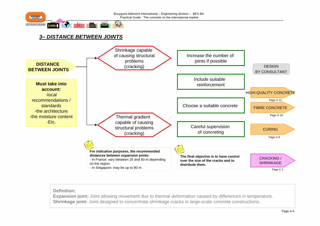
DISTANCE BETWEEN JOINTS
For indicative purposes, the recommended distances between expansion joints:- In France: vary between 25 and 50 m depending on the region - In Singapore: may be up to 80 m
CURING
FIBRE CONCRETE
Shrinkage capable of causing structural
problems(cracking)
Careful supervision of concreting
Thermal gradient capable of causingstructural problems
(cracking)
Include suitable reinforcement
Increase the number of joints if possible
Choose a suitable concrete
Must take into account:
-local recommendations /
standards-the architecture
-the moisture content-Etc.
Definition:Expansion joint: Joint allowing movement due to thermal deformation caused by differences in temperature. Shrinkage joint: Joint designed to concentrate shrinkage cracks in large-scale concrete constructions.
The final objective is to have control over the size of the cracks and to distribute them.
3– DISTANCE BETWEEN JOINTS
CRACKING /SHRINKAGE
DESIGNBY CONSULTANT
Page G 18
Page C 2
Page G 8
HIGH-QUALITY CONCRETE
Page G 12

Bouygues bâtiment International – Engineering division – BES BA Practical Guide : The concrete on the international market
Page A 5
LARGE UNITS
CURING
Choose a suitable concrete
Careful supervision of installation
LARGE CONCRETE CONSTRUCTIONS
FORMWORK
Concerns units thicker than 0.8 m:- Raft foundations
- Large load-bearing units-etc.
In general, cracking will occur when the difference in temperature Is greater than 20°C either between 2 concrete sections or between the concrete element and the external air
Surface or throughout cracking resulting
from the concrete’s exothermic reaction
CRACKING /SHRINKAGE
4 – LARGE UNITS
METHOD OF PHASING / PLACING
Page G 27
Page C 2
Page G 2
Page G 8

Bouygues bâtiment International – Engineering division – BES BA Practical Guide : The concrete on the international market
Page A 6
PATHOLOGY /PREVENTION ON FACINGS
ATTRACTIVE APPEARANCE
Defect in appearance, colour, texture
Comply with the construction specifications
Careful supervisionof installation
Choose a suitable concrete
Concerns constructions and buildings for which the architects want
to highlight its attractive surface
appearance:-Numerous public
buildings (hospitals, schools,
administrative buildings, etc.)
-Etc.
5 – ATTRACTIVE APPEARANCE
Page C 17
ARCHITECTONIC CONCRETE
Page G 19

Bouygues bâtiment International – Engineering division – BES BA Practical Guide : The concrete on the international market
Page B 1
Part B: SURROUNDINGS AND EXPOSURE OF THE CONSTRUCTION
1 – GEOGRAPHICAL ZONE …………………………………………. Page B 2
2 – IMMEDIATE SURROUNDINGS…………………………………………....Page B 3
3 – GROUND / WATER TABLE…………………………………….…..Page B 4
4 – PARTICULAR CONDITIONS OF USE ……………………….…..Page B 5
5 – BUILDING LIFE TIME……………………………………………….Page B 6
APPENDIX – CORROSIVE EFFECT OF CHEMICALS………….…..Page B 7
Above all, when arriving in a new country, take a close look at nearby constructions, particularly constructions that are damaged, under repair or repaired and look for the reasons.
Take a close look, also, at the general appearance of nearby constructions, including the appearance of the concrete, the existence of exposed reinforcement and efflorescence (whitish stains) on vertical surfaces.
Bouygues bâtiment International – Engineering division – BES BA Practical Guide : The concrete on the international market
Page B 2
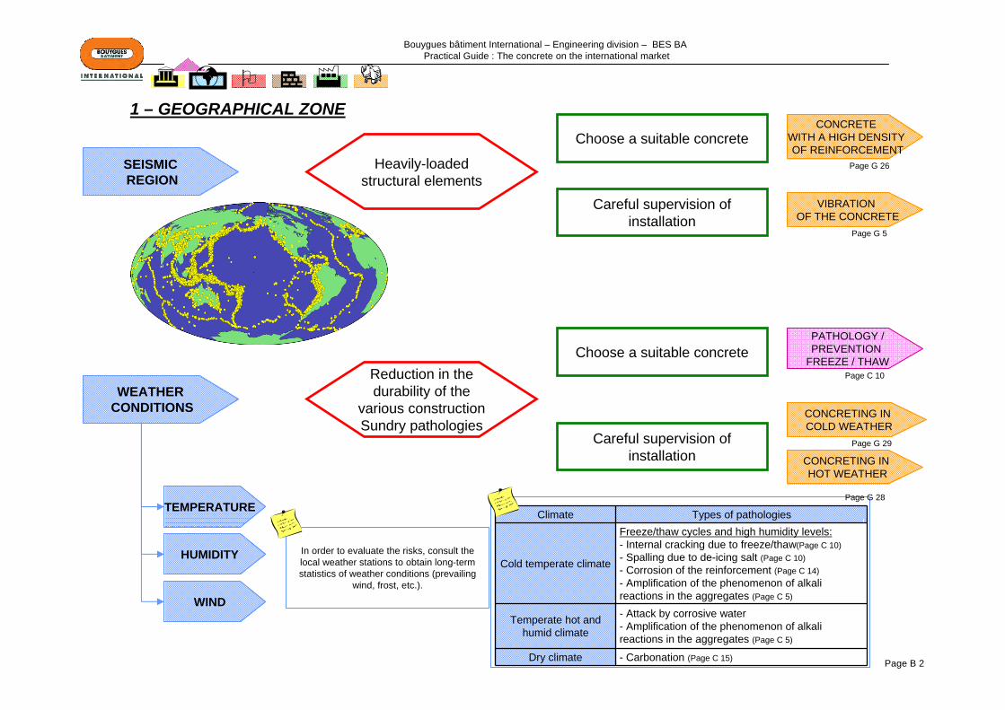
SEISMIC REGION
VIBRATION OF THE CONCRETE
Heavily-loaded structural elements
WEATHER CONDITIONS
TEMPERATURE
CONCRETING IN COLD WEATHER
CONCRETING IN HOT WEATHER
Careful supervision of installation
Choose a suitable concreteReduction in the durability of the
various constructionSundry pathologies
HUMIDITY
WIND
Careful supervision of installation
Choose a suitable concreteCONCRETE
WITH A HIGH DENSITY OF REINFORCEMENT
Climate Types of pathologies
Cold temperate climate
Freeze/thaw cycles and high humidity levels:- Internal cracking due to freeze/thaw(Page C 10)- Spalling due to de-icing salt (Page C 10)- Corrosion of the reinforcement (Page C 14)- Amplification of the phenomenon of alkali reactions in the aggregates (Page C 5)
Temperate hot and humid climate
- Attack by corrosive water - Amplification of the phenomenon of alkali reactions in the aggregates (Page C 5)
Dry climate - Carbonation (Page C 15)
In order to evaluate the risks, consult the local weather stations to obtain long-term statistics of weather conditions (prevailing
wind, frost, etc.).
PATHOLOGY /PREVENTION
FREEZE / THAW
1 – GEOGRAPHICAL ZONE
Page C 10
Page G 29
Page G 26
Page G 5
Page G 28
Bouygues bâtiment International – Engineering division – BES BA Practical Guide : The concrete on the international market
Page B 3
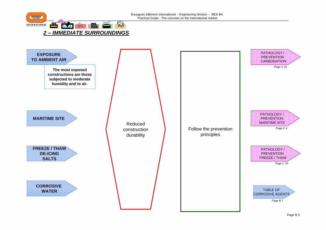
MARITIME SITE
EXPOSURE TO AMBIENT AIR
CORROSIVE WATER
FREEZE / THAWDE-ICING
SALTS
PATHOLOGY /PREVENTION
FREEZE / THAW
PATHOLOGY / PREVENTION
MARITIME SITE
PATHOLOGY / PREVENTION CARBONATION
Follow the prevention principles
Reduced construction
durability
The most exposed constructions are those subjected to moderate
humidity and to air.
2 – IMMEDIATE SURROUNDINGS
TABLE OF CORROSIVE AGENTS
Page C 15
Page B 7
Page C 4
Page C 10

Bouygues bâtiment International – Engineering division – BES BA Practical Guide : The concrete on the international market
Page B 4
WATER TABLE
GROUND
SULPHATESPRESENT AND
CONCENTRATION
"NON-TRADITIONAL"ELEMENTS IN THE
GROUND
SALTS CONTENT AND CONCENTRATION
pH OF THE WATER
Examples:- Gypsum - Anhydrite-Etc.
Examples:-Heavy metals-Hydrocarbons-Erc.
FRESH WATER
- Magnesium- Sulphates- Ammonium
Identify the risk(s) and follow the prevention
principles
Reduced construction
durability
3 – GROUND / WATER TABLE
TABLE OF CORROSIVE AGENTS
Page B 7
Bouygues bâtiment International – Engineering division – BES BA Practical Guide : The concrete on the international market
Page B 5
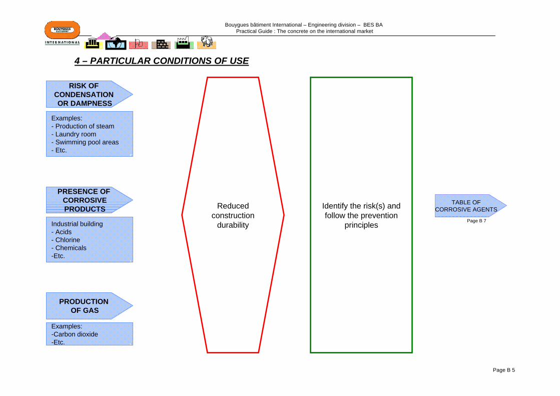
RISK OF CONDENSATION OR DAMPNESS
PRESENCE OF CORROSIVEPRODUCTS
PRODUCTION OF GAS
Examples:- Production of steam- Laundry room- Swimming pool areas- Etc.
Industrial building- Acids - Chlorine- Chemicals-Etc.
Examples:-Carbon dioxide-Etc.
Identify the risk(s) and follow the prevention
principles
Reduced construction
durability
4 – PARTICULAR CONDITIONS OF USE
TABLE OF CORROSIVE AGENTS
Page B 7
Bouygues bâtiment International – Engineering division – BES BA Practical Guide : The concrete on the international market
Page B 6
PERIOD OF USE
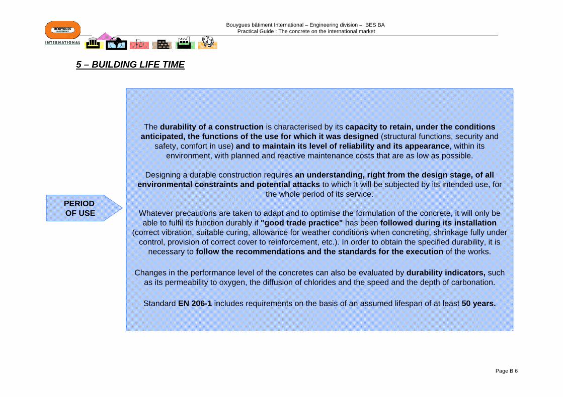
The durability of a construction is characterised by its capacity to retain, under the conditions anticipated, the functions of the use for which it was designed (structural functions, security and
safety, comfort in use) and to maintain its level of reliability and its appearance, within its environment, with planned and reactive maintenance costs that are as low as possible.
Designing a durable construction requires an understanding, right from the design stage, of all environmental constraints and potential attacks to which it will be subjected by its intended use, for
the whole period of its service.
Whatever precautions are taken to adapt and to optimise the formulation of the concrete, it will only be able to fulfil its function durably if "good trade practice" has been followed during its installation
(correct vibration, suitable curing, allowance for weather conditions when concreting, shrinkage fully under control, provision of correct cover to reinforcement, etc.). In order to obtain the specified durability, it is
necessary to follow the recommendations and the standards for the execution of the works.
Changes in the performance level of the concretes can also be evaluated by durability indicators, such as its permeability to oxygen, the diffusion of chlorides and the speed and the depth of carbonation.
Standard EN 206-1 includes requirements on the basis of an assumed lifespan of at least 50 years.
5 – BUILDING LIFE TIME
Bouygues bâtiment International – Engineering division – BES BA Practical Guide : The concrete on the international market
Page B 7
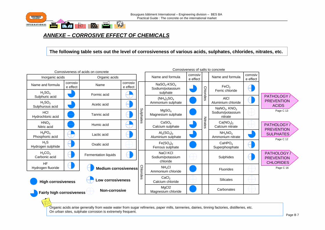
Corrosiveness of acids on concreteInorganic acids Organic acids
Name and formula corrosive effect Name corrosiv
e effectH2SO4
Sulphuric acid Formic acid
H2SO3Sulphurous acid Acetic acid
HClHydrochloric acid Tannic acid
HNO3Nitric acid Humic acid
H8PO4Phosphoric acid Lactic acid
H2SHydrogen sulphide Oxalic acid
H2CO3Carbonic acid Fermentation liquids
HFHydrogen fluoride
Corrosiveness of salts to concrete
Name and formula corrosive effect Name and formula corrosiv
e effect
Sulphates
NaSO4-KSO4Sodium/potassium
sulphate
Chlorides
FeCl2Ferric chloride
(NH4)3SO4Ammonium sulphate
AlClAluminium chloride
MgSO4Magnesium sulphate N
itrates
NaNO3, KNO3Sodium/potassium
nitrate CaSO4
Calcium sulphateCa(NO3)2
Calcium nitrate
Al2(SO4)3Aluminium sulphate
NH4NO3Ammonium nitrate
Fe(SO4)3Ferrous sulphate
CaHPO4Superphosphate
Chlorides
NaCl KClSodium/potassium
chlorideSulphides
NH4ClAmmonium chloride Fluorides
CaCl2Calcium chloride Silicates
MgCl2Magnesium chloride Carbonates
High corrosiveness
Fairly high corrosiveness
Medium corrosiveness
Low corrosiveness
Non-corrosive
Organic acids arise generally from waste water from sugar refineries, paper mills, tanneries, dairies, tinning factories, distilleries, etc.On urban sites, sulphate corrosion is extremely frequent.
PATHOLOGY / PREVENTION
ACIDS
PATHOLOGY / PREVENTION SULPHATES
PATHOLOGY /PREVENTION CHLORIDES
The following table sets out the level of corrosiveness of various acids, sulphates, chlorides, nitrates, etc.
ANNEXE – CORROSIVE EFFECT OF CHEMICALS
Page C 13
Page C 12
Page C 16
Bouygues bâtiment International – Engineering division – BES BA Practical Guide : The concrete on the international market
Page C 1
Part C: CONCRETE PATHOLOGY / RISK PREVENTION DATA SHEETS
1 – CRACKING / SHRINKAGE …………………………………………………………….…......Page C 2
2 – MARITIME ENVIRONMENT..............................................................................................Page C 4
3 – ALKALI REACTION…………………………………………………………………..….………Page C 5
4 – FREEZE / THAW…………………………………………………………………..….………....Page C 10
5 – SULPHATE ATTACK ………………………………………………………………………..….Page C 12
6 – ACID ATTACK ……………………………………………………………………………….…..Page C 13
7 – CORROSION OF THE REINFORCEMENT ……………………………………….…….…..Page C14
8 – CARBONATION……………………………………………………………………………….…Page C 15
9 – CHLORIDE ATTACK ………………………………………………………………………..…..Page C 16
10 – SURFACE APPEARANCE……………………………………………………………….…….Page C 17
APPENDIX – SUMMARY OF THE ESSENTIAL CRITERIA FOR A DURABLE CONCRETE ....Page C 20
Bouygues bâtiment International – Engineering division – BES BA Practical Guide : The concrete on the international market
Page C 2
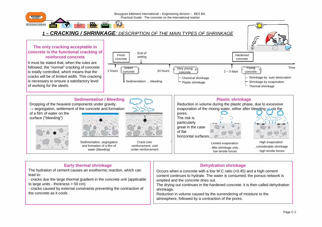
Sedimentation / BleedingDropping of the heaviest components under gravity.→ segregation, settlement of the concrete and formation of a film of water on the surface ("bleeding")
Plastic shrinkageReduction in volume during the plastic phase, due to excessive evaporation of the mixing water, either after bleeding or via the pores.The risk isparticularlygreat in the caseof flathorizontal surfaces.
Early thermal shrinkageThe hydration of cement causes an exothermic reaction, which canlead to: - cracks due the large thermal gradient in the concrete unit (applicable to large units - thickness > 50 cm)- cracks caused by external constraints preventing the contraction of the concrete as it cools.
Dehydration shrinkageOccurs when a concrete with a low W:C ratio (<0.45) and a high cement content continues to hydrate. The water is consumed, the porous network is emptied and the concrete dries out.The drying out continues in the hardened concrete: it is then called dehydrationshrinkage.Reduction in volume caused by the surrendering of moisture to the atmosphere, followed by a contraction of the pores.
The only cracking acceptable in concrete is the functional cracking of
reinforced concreteIt must be stated that, when the rules are followed, the "normal" cracking of concrete is totally controlled, which means that the cracks will be of limited width. This cracking is necessary to ensure a satisfactory level of working for the steels.
1 – CRACKING / SHRINKAGE: DESCRIPTION OF THE MAIN TYPES OF SHRINKAGE
Sedimentation, segregation and formation of a film of
water (bleeding)
Crack over reinforcement, void under reinforcement
Limited evaporation:. little shrinkage only .
low tensile forces
High evaporation . considerable shrinkage
. high tensile forces
Fresh concrete
Sedimentation … bleeding
24 hours 2 – 3 daysGreen
concreteVery young
concreteYoung
concreteTime
Chemical shrinkagePlastic shrinkage
Shrinkage by auto desiccationShrinkage by evaporationThermal shrinkage
End of setting Hardened
concrete
2 hours

Bouygues bâtiment International – Engineering division – BES BA Practical Guide : The concrete on the international market
Page C 3
Presetting: 2 to 4 hours. Setting: 4 to 8 hours. Hardening: 8 to 50 hours. Long term: ≥ 50 hours
BLEEDING PLASTIC SHRINKAGE THERMAL SHRINKAGE DEHYDRATION SHRINKAGE
•Long period of vibration•Large thickness of fresh concrete
•Long time before setting
•Unstable suspension (lack of fine components, insufficient quantity of cement, excessive quantity of water, etc.)
•Structural units with a high surface/volume ratio
•Slow setting
•High dehydration
•Shape of the units (large sizes)
•Poor insulation of the formwork
•Type of cement (high hydration heat)
•High cement content
•High evaporation
•Important phenomenon for high-performance concretes (W:C ratio ~ 0.3) – endogenous shrinkage with no exchange with the outside (internal dehydration)
•Formulate the concrete properly (enough fines, limited W:C ratio)
•Accelerate setting (avoid slow setting)
•Vibrate well (but NOT the reinforcement)
•Cure effectivelyWIND = DANGER
•Use of polypropylene fibres for concretes particularly exposed to severe weather conditions
•Avoid slow setting
•Reduce the thermal gradient(cement with low heat release)
•Add additional reinforcementsif necessary
•Avoid thermal shock on striking formwork
•Enough joints
•Reinforce, if applicable, to distribute cracking
Never add extra water as it - Delays hardening- Increases evaporation
PRINCIPLES
FACTORS
1 – CRACKING / SHRINKAGE (contd.): SHRINKAGE OVER TIME…
OF
PREVENTION
CAUSES
AND
Typical plastic shrinkage cracks

Bouygues bâtiment International – Engineering division – BES BA Practical Guide : The concrete on the international market
Page C 4
Preponderant causes and factors
Chemical parameters (corrosive ions)
Exposure parameters (tides and fluctuations in sea level, freeze/thaw cycle, activation in high temperatures)
Mechanical parameters (abrasion)
Principles of prevention
Formulation with a sufficient quantity of a suitable cementCements suitable for sea water
Provide the correct cover to the reinforcement
A compact and low permeability concrete (Page G 12)
the use of super plasticisers or water-reduction additivesfor a relatively low W:C ratioOptimisation of the granular skeleton
Careful placing and curingAdequate vibration (Page G 5)
Effective curing (Page G 8)
Phenomenon of sea water attack
Action of chlorides (corrosion, etc.)(Page C 16)
Action of sulphates (Page C 12)
Action of CO2 (carbonation) (Page C 15)
Attack conditioned by alternating wet / dry (inter-tidal zone) and the temperature of the water
2 – MARITIME ENVIRONMENT

Bouygues bâtiment International – Engineering division – BES BA Practical Guide : The concrete on the international market
Page C 5
Preponderant causes and factors(occurring in combination)
Potentially reactive aggregateActive alkalisRelative humidity (external environment) > 70 -
80%
3 – ALKALI REACTION
Phenomenon of alkali reaction
Symptoms (appearing within 2 to 10 years)Cracking: the cracks are progressive and they can open up by 0.5 mm/yearExudations, pustules or craters, colouration or discolouration, movements and deformation
of the construction
Tests to determine the risk of damage by alkali reaction may extend over several months.
silica
water
alkalis
Formation of an expansive gel
Cracking expansion
Bouygues bâtiment International – Engineering division – BES BA Practical Guide : The concrete on the international market
Page C 6
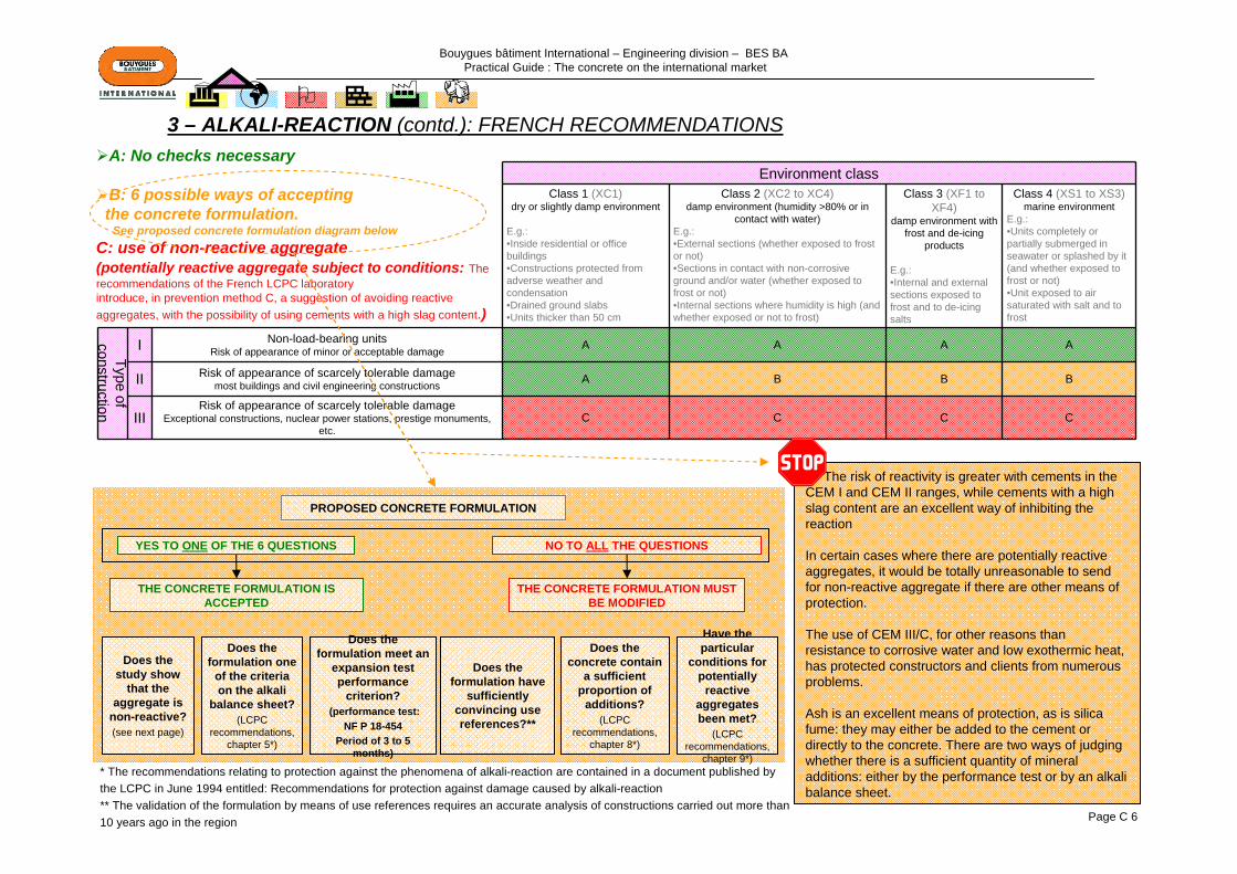
The risk of reactivity is greater with cements in the CEM I and CEM II ranges, while cements with a high slag content are an excellent way of inhibiting the reaction
In certain cases where there are potentially reactive aggregates, it would be totally unreasonable to send for non-reactive aggregate if there are other means of protection.
The use of CEM III/C, for other reasons than resistance to corrosive water and low exothermic heat, has protected constructors and clients from numerous problems.
Ash is an excellent means of protection, as is silica fume: they may either be added to the cement or directly to the concrete. There are two ways of judging whether there is a sufficient quantity of mineral additions: either by the performance test or by an alkali balance sheet.
Environment classClass 1 (XC1)
dry or slightly damp environment
E.g.:•Inside residential or office buildings•Constructions protected from adverse weather and condensation•Drained ground slabs•Units thicker than 50 cm
Class 2 (XC2 to XC4)damp environment (humidity >80% or in
contact with water)E.g.:•External sections (whether exposed to frost or not)•Sections in contact with non-corrosive ground and/or water (whether exposed to frost or not)•Internal sections where humidity is high (and whether exposed or not to frost)
Class 3 (XF1 to XF4)
damp environment with frost and de-icing
products
E.g.:•Internal and external sections exposed to frost and to de-icing salts
Class 4 (XS1 to XS3)marine environment
E.g.: •Units completely or partially submerged in seawater or splashed by it (and whether exposed to frost or not)•Unit exposed to air saturated with salt and to frost
Type of construction
I Non-load-bearing units Risk of appearance of minor or acceptable damage A A A A
II Risk of appearance of scarcely tolerable damage most buildings and civil engineering constructions A B B B
IIIRisk of appearance of scarcely tolerable damage
Exceptional constructions, nuclear power stations, prestige monuments, etc.
C C C C
A: No checks necessary
B: 6 possible ways of acceptingthe concrete formulation.
See proposed concrete formulation diagram belowC: use of non-reactive aggregate(potentially reactive aggregate subject to conditions: The recommendations of the French LCPC laboratory introduce, in prevention method C, a suggestion of avoiding reactiveaggregates, with the possibility of using cements with a high slag content.)
3 – ALKALI-REACTION (contd.): FRENCH RECOMMENDATIONS
Does the study show
that the aggregate is
non-reactive?(see next page)
Does the formulation one
of the criteria on the alkali
balance sheet?(LCPC
recommendations, chapter 5*)
Does the formulation meet an
expansion test performance
criterion?(performance test:
NF P 18-454Period of 3 to 5
months)
Does the formulation have
sufficiently convincing use references?**
Does the concrete contain
a sufficient proportion of
additions?(LCPC
recommendations, chapter 8*)
Have the particular
conditions for potentially
reactive aggregates been met?
(LCPC recommendations,
chapter 9*)
THE CONCRETE FORMULATION IS ACCEPTED
THE CONCRETE FORMULATION MUST BE MODIFIED
PROPOSED CONCRETE FORMULATION
YES TO ONE OF THE 6 QUESTIONS NO TO ALL THE QUESTIONS
* The recommendations relating to protection against the phenomena of alkali-reaction are contained in a document published by the LCPC in June 1994 entitled: Recommendations for protection against damage caused by alkali-reaction** The validation of the formulation by means of use references requires an accurate analysis of constructions carried out more than10 years ago in the region

Bouygues bâtiment International – Engineering division – BES BA Practical Guide : The concrete on the international market
Page C 7
3 – ALKALI-REACTION (contd.): GENERALAGGREGATE CHARACTERISATION PROCESS
Aggregate identification
Petrographic study
Screen test
Long-term test
Carbonated rockwhere SiO2 < 4%
Relative mineralspecies < 4%
Flint > 70%
40% < Flint < 70%
Qualification following the test
Expansion > Threshold
PR
PR
PRP
NR
YES
YES
YES
YES
YES
NO
NO
NO
NO
NO
NO
*
*) If the PR qualification is considered to be sufficient, the procedure may be stopped
Screen test: this is a test that uses a greatly accelerated procedure capable of diagnosing, in less than one week, the reactivity of the alkalis in an aggregate which is non-reactive, potentially reactive or potentially reactive with a Pessimum effect.Reference method: accelerated autoclave test on mortar (5 days)Alternatives: Accelerated "Microbar" test; Chemical kinetic test
Long-term test: this is a diagnosis procedure which, although accelerated in comparison with the reaction kinetics observed on constructions, is sufficiently close to actual conditions to take into account the effective sensitivity of the aggregates. Principle: Expansion test on concrete samples (measurements taken at: 1 month, 2 months, 3 months, 4 months, 6 months and 8 months)
NR: Non-reactiveName given to aggregates for hydraulic concretes which, whatever their conditions of use, will not cause alkali-reaction problems
PR: Potentially reactiveName given to aggregates likely, under certain conditions, to cause alkali-reaction problems
PRP: potentially reactive with a Pessimum effectName given to aggregates which, although rich in reactive silica, can be used with no risk of problems, provided that their use meets theconditions described in the document "Recommendations for protection against damage caused by alkali- reaction"

Bouygues bâtiment International – Engineering division – BES BA Practical Guide : The concrete on the international market
Page C 8
France United Kingdom
LCPC 1994: Recommendations for protection against damage caused by alkali-reaction
BS 812-104: Testing aggregates. Method for qualitative and quantitative petrographic examination of aggregates
XP P 18-594, Aggregates - Alkali reactivity test method BS 812-123: Testing aggregates: Method for determination of alkali-silica reactivity. Concrete prism method
FD P 18-542, Aggregates - Qualification criteria for natural aggregates for hydraulic concrete in respect of alkali
reaction
BS 7943: Guide to the interpretation of petrographical examinations for alkali-silica reactivity
NF P 18-454, Concrete - Reactivity of a concrete mix in respect of alkali reaction - Performance test
3 – ALKALI-REACTION (contd.): NORMATIVE TEXTS FRANCE AND GREAT BRITAIN
United Kingdom – BRE Centre for Concrete ConstructionAlkali silica reaction in concrete
Internet site: www.bre.co.uk/
BRE Digest 330 Part 1Background to the guidance notes
BRE Digest 330 Part 2Detailed guidance for new construction
BRE Digest 330 Part 3Worked examples
BRE Digest 330 Part 4Simplified guidance for new construction using normal
reactivity aggregates

Bouygues bâtiment International – Engineering division – BES BA Practical Guide : The concrete on the international market
Page C 9
3 – ALKALI-REACTION (contd.): AMERICAN NORMATIVE TEXTS
Name of the test Period of the test CommentsASTM C227: Standard Test Method for Potential Alkali Reactivity of Cement-Aggregate Combinations (Mortar-Bar
Method)
Varies: first measurement at 14 days, then at 1, 2, 3, 4, 6, 9 and 12 months, then every 6 months
The test must not cause significant expansion of carbonated aggregates. Long test period. The expansion is not necessarily caused by the alkali
reaction of the aggregate
ASTM C289: Determination of the silica alkali reactivity of aggregates (chemical
method)24 hours Rapid results. Certain aggregates give low expansion, even if they have a
high silica content. Not very reliable
ASTM C294: Natural mineral components of aggregates
Short period - as long as the visual examination takes
These descriptions are used to characterise the natural minerals forming the aggregates' sources
ASTM C295: Petrographic examination of the aggregates in the concrete
Short period - visual examination, not requiring long test periods
Generally includes an optical microscopy. May also include an X-ray, thermal or infra-red analysis - See ASTM C294
ASTM C441: Effectiveness of mineral or slag additions in concrete expansion prevention due to silica alkali reaction
Varies: first measurement at 14 days, then at 1, 2, 3, 4, 5, 9 and 12 months, then every 6 months
Highly-reactive artificial aggregate, may not represent real aggregatesPyrex contains alkalis
ASTM C856: Petrographic examination of hardened concrete
Short period - including the preparation of the samples and
the visual and microscopic examinations
Samples may be examined with a stereo microscope, a polarising microscope, a metallographic microscope and a scanning electron
microscope
ASTM C856: Uranium acetate treatment procedure Immediate results
Identifies small quantities of gel which may or may not cause expansionOpal, a natural aggregate, and carbonated paste may light up - the results
must be interpreted accordinglyThe tests may be supplemented by a petrographic examination and a
physical test in order to determine the expansion of the concrete.
ASTM C1260 Potential alkali reactivity of aggregates (mortar bar method) 16 days
More rapid alternative to ASTM C227Used for aggregates reacting slowly or those whose expansion is delayed in
relation to the reaction
ASTM C1293: Determination of Length Change of Concrete Due to Alkali-Silica
Reaction (concrete prism test)
Varies: first measurements at 7 days, then 28 and 56 days, then at 3, 6, 9 and 12 months, then
every 6 months
Requires a long test period to give significant resultsTo be used to supplement ASTM C227, C295, C289 and C1260
ASTM C1567: Potential Alkali-Silica Reactivity of Combinations of
Cementitious Materials and Aggregate (Accelerated Mortar-Bar Method)
16 daysMore rapid alternative to ASTM C1293
Used for aggregates reacting slowly or those whose expansion is delayed in relation to the reaction
Bouygues bâtiment International – Engineering division – BES BA Practical Guide : The concrete on the international market
Page C 10
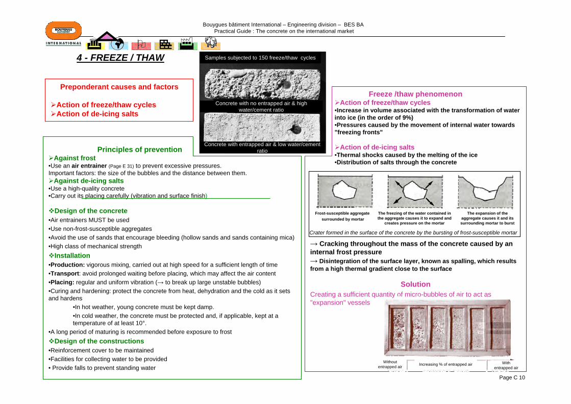
Freeze /thaw phenomenonAction of freeze/thaw cycles
•Increase in volume associated with the transformation of water into ice (in the order of 9%)•Pressures caused by the movement of internal water towards "freezing fronts"
Action of de-icing salts•Thermal shocks caused by the melting of the ice•Distribution of salts through the concrete
→ Cracking throughout the mass of the concrete caused by an internal frost pressure→ Disintegration of the surface layer, known as spalling, which results from a high thermal gradient close to the surface
SolutionCreating a sufficient quantity of micro-bubbles of air to act as "expansion" vessels
Principles of preventionAgainst frost
•Use an air entrainer (Page E 31) to prevent excessive pressures. Important factors: the size of the bubbles and the distance between them.
Against de-icing salts•Use a high-quality concrete•Carry out its placing carefully (vibration and surface finish)
Design of the concrete•Air entrainers MUST be used •Use non-frost-susceptible aggregates•Avoid the use of sands that encourage bleeding (hollow sands and sands containing mica)•High class of mechanical strength
Installation•Production: vigorous mixing, carried out at high speed for a sufficient length of time•Transport: avoid prolonged waiting before placing, which may affect the air content•Placing: regular and uniform vibration (→ to break up large unstable bubbles)•Curing and hardening: protect the concrete from heat, dehydration and the cold as it sets and hardens
•In hot weather, young concrete must be kept damp.•In cold weather, the concrete must be protected and, if applicable, kept at a temperature of at least 10°.
•A long period of maturing is recommended before exposure to frostDesign of the constructions
•Reinforcement cover to be maintained•Facilities for collecting water to be provided• Provide falls to prevent standing water
4 - FREEZE / THAW
Preponderant causes and factors
Action of freeze/thaw cycles Action of de-icing salts
Crater formed in the surface of the concrete by the bursting of frost-susceptible mortar
Frost-susceptible aggregatesurrounded by mortar
The freezing of the water contained in the aggregate causes it to expand and
creates pressure on the mortar
The expansion of the aggregate causes it and its surrounding mortar to burst
Samples subjected to 150 freeze/thaw cycles
Concrete with no entrapped air & high water/cement ratio
Concrete with entrapped air & low water/cement ratio
Without entrapped air Increasing % of entrapped air With
entrapped air

Bouygues bâtiment International – Engineering division – BES BA Practical Guide : The concrete on the international market
Page C 11
4 – FREEZE / THAW (contd.): MAIN NORMATIVE TEXTS
FranceLCPC 2003 - Recommendations for the durability of hardened concretes subjected to frost
XP P 18-420, Concrete - Spalling test on the surfaces of hardened concrete exposed to frost in the presence of saline solutions
XP P 18-424, Concrete - Freezing test on hardened concrete - Freezing in water - Thawing in water XP P 18-425, Concrete - Freezing test on hardened concrete - Freezing in air - Thawing in water
FD P 18-326 Frost zones in France
United States
ASTM C666: Standard Test Method for Resistance of Concrete to Rapid Freezing and Thawing
ASTM C617: Standard Practice for Capping Cylindrical Concrete Specimens
ASTM C682: Standard Practice for Evaluation of Frost Resistance of Coarse Aggregates in Air Entrained Concrete by Critical Dilation Procedures
ASTM C672: Standard Test Method for Scaling Resistance of Concrete Surfaces Exposed to De-icing Chemicals
Russia
GOST 10060.0: Concretes - Method for the determination of frost resistance. General requirements
GOST 10060.1: Basic method for the determination of frost resistance
GOST 10060.2: Rapid method for the determination of frost-resistance by repeated alternated freezing and thawing
GOST 10060.3: Concretes - Dilatometric rapid method for determination of frost-resistance
GOST 10060.4: Concrete. Structure mechanical rapid method for the determination of frost resistance
GOST 26134: Concretes. Ultrasonic method of frost resistance determination
Bouygues bâtiment International – Engineering division – BES BA Practical Guide : The concrete on the international market
Page C 12
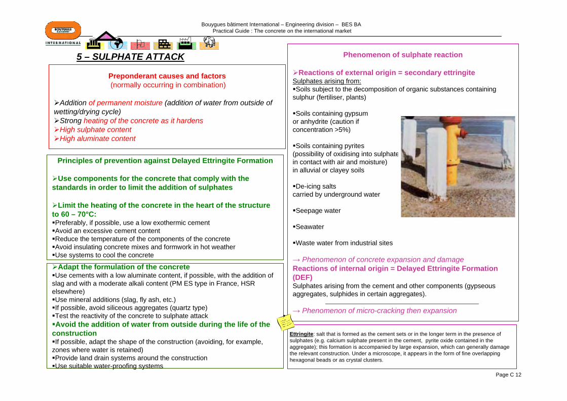
Preponderant causes and factors(normally occurring in combination)
Addition of permanent moisture (addition of water from outside of wetting/drying cycle)
Strong heating of the concrete as it hardensHigh sulphate contentHigh aluminate content
Phenomenon of sulphate reaction
Reactions of external origin = secondary ettringite Sulphates arising from:Soils subject to the decomposition of organic substances containing
sulphur (fertiliser, plants)
Soils containing gypsumor anhydrite (caution ifconcentration >5%)
Soils containing pyrites (possibility of oxidising into sulphatesin contact with air and moisture) in alluvial or clayey soils
De-icing saltscarried by underground water
Seepage water
Seawater
Waste water from industrial sites
→ Phenomenon of concrete expansion and damageReactions of internal origin = Delayed Ettringite Formation (DEF)Sulphates arising from the cement and other components (gypseousaggregates, sulphides in certain aggregates).
→ Phenomenon of micro-cracking then expansion
5 – SULPHATE ATTACK
Ettringite: salt that is formed as the cement sets or in the longer term in the presence of sulphates (e.g. calcium sulphate present in the cement, pyrite oxide contained in the aggregate); this formation is accompanied by large expansion, which can generally damage the relevant construction. Under a microscope, it appears in the form of fine overlapping hexagonal beads or as crystal clusters.
Principles of prevention against Delayed Ettringite Formation
Use components for the concrete that comply with the standards in order to limit the addition of sulphates
Limit the heating of the concrete in the heart of the structure to 60 – 70°C:Preferably, if possible, use a low exothermic cementAvoid an excessive cement contentReduce the temperature of the components of the concreteAvoid insulating concrete mixes and formwork in hot weatherUse systems to cool the concrete
Adapt the formulation of the concreteUse cements with a low aluminate content, if possible, with the addition of
slag and with a moderate alkali content (PM ES type in France, HSR elsewhere)Use mineral additions (slag, fly ash, etc.)If possible, avoid siliceous aggregates (quartz type)Test the reactivity of the concrete to sulphate attackAvoid the addition of water from outside during the life of the
constructionIf possible, adapt the shape of the construction (avoiding, for example,
zones where water is retained)Provide land drain systems around the constructionUse suitable water-proofing systems
Bouygues bâtiment International – Engineering division – BES BA Practical Guide : The concrete on the international market
Page C 13
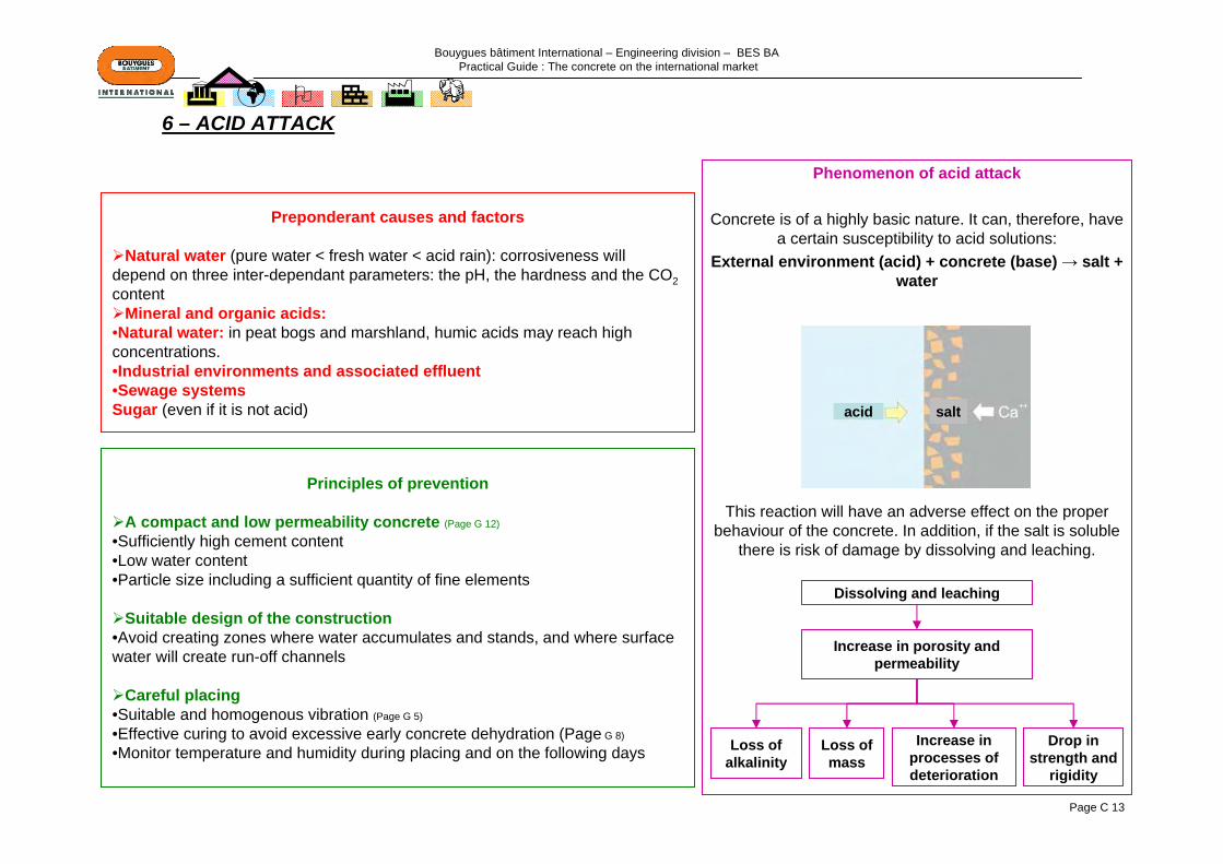
Principles of prevention
A compact and low permeability concrete (Page G 12)
•Sufficiently high cement content•Low water content•Particle size including a sufficient quantity of fine elements
Suitable design of the construction•Avoid creating zones where water accumulates and stands, and where surface water will create run-off channels
Careful placing•Suitable and homogenous vibration (Page G 5)
•Effective curing to avoid excessive early concrete dehydration (Page G 8)
•Monitor temperature and humidity during placing and on the following days
Preponderant causes and factors
Natural water (pure water < fresh water < acid rain): corrosiveness will depend on three inter-dependant parameters: the pH, the hardness and the CO2content
Mineral and organic acids:•Natural water: in peat bogs and marshland, humic acids may reach high concentrations. •Industrial environments and associated effluent•Sewage systemsSugar (even if it is not acid)
Phenomenon of acid attack
Concrete is of a highly basic nature. It can, therefore, have a certain susceptibility to acid solutions:
External environment (acid) + concrete (base) → salt + water
This reaction will have an adverse effect on the proper behaviour of the concrete. In addition, if the salt is soluble
there is risk of damage by dissolving and leaching.
Dissolving and leaching
Increase in porosity and permeability
Increase in processes of deterioration
Loss of mass
Loss of alkalinity
Drop in strength and
rigidity
6 – ACID ATTACK
acid salt
Bouygues bâtiment International – Engineering division – BES BA Practical Guide : The concrete on the international market
Page C 14
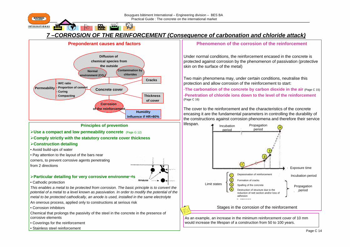
Phenomenon of the corrosion of the reinforcement
Under normal conditions, the reinforcement encased in the concrete is protected against corrosion by the phenomenon of passivation (protective skin on the surface of the metal)
Two main phenomena may, under certain conditions, neutralise this protection and allow corrosion of the reinforcement to start:-The carbonation of the concrete by carbon dioxide in the air (Page C 15)
-Penetration of chloride ions down to the level of the reinforcement (Page C 16)
The cover to the reinforcement and the characteristics of the concrete encasing it are the fundamental parameters in controlling the durability of the constructions against corrosion phenomena and therefore their service lifespan.
Preponderant causes and factors
- W/C ratio- Proportion of cement- Curing- Compacting
Permeability
Diffusion of chemical species from
the outside
Cracks
Thickness of cover
HumidityInfluence if HR>80%
Corrosion of the reinforcement
Concrete cover
Principles of preventionUse a compact and low permeability concrete (Page G 12)
Comply strictly with the statutory concrete cover thicknessConstruction detailing
• Avoid build-ups of water • Pay attention to the layout of the bars nearcorners, to prevent corrosive agents penetratingfrom 2 directions
Particular detailing for very corrosive environments• Cathodic protection This enables a metal to be protected from corrosion. The basic principle is to convert the potential of a metal to a level known as passivation. In order to modify the potential of the metal to be protected cathodically, an anode is used, installed in the same electrolyteAn onerous process, applied only to constructions at serious risk• Corrosion inhibitorsChemical that prolongs the passivity of the steel in the concrete in the presence of corrosive elements• Coverings for the reinforcement• Stainless steel reinforcement
Normalenvironment (CO2)
Contamination by chlorides
As an example, an increase in the minimum reinforcement cover of 10 mm would increase the lifespan of a construction from 50 to 100 years.
7 –CORROSION OF THE REINFORCEMENT (Consequence of carbonation and chloride attack)
Limit states
Depassivation of reinforcement
Exposure time
Incubation period
Formation of cracks
Spalling of the concrete
Destruction of structure due to the reduction of nett section and/or loss of adhesion
Propagation period
Incubation period
Propagation period
Stages in the corrosion of the reinforcement
Bouygues bâtiment International – Engineering division – BES BA Practical Guide : The concrete on the international market
Page C 15
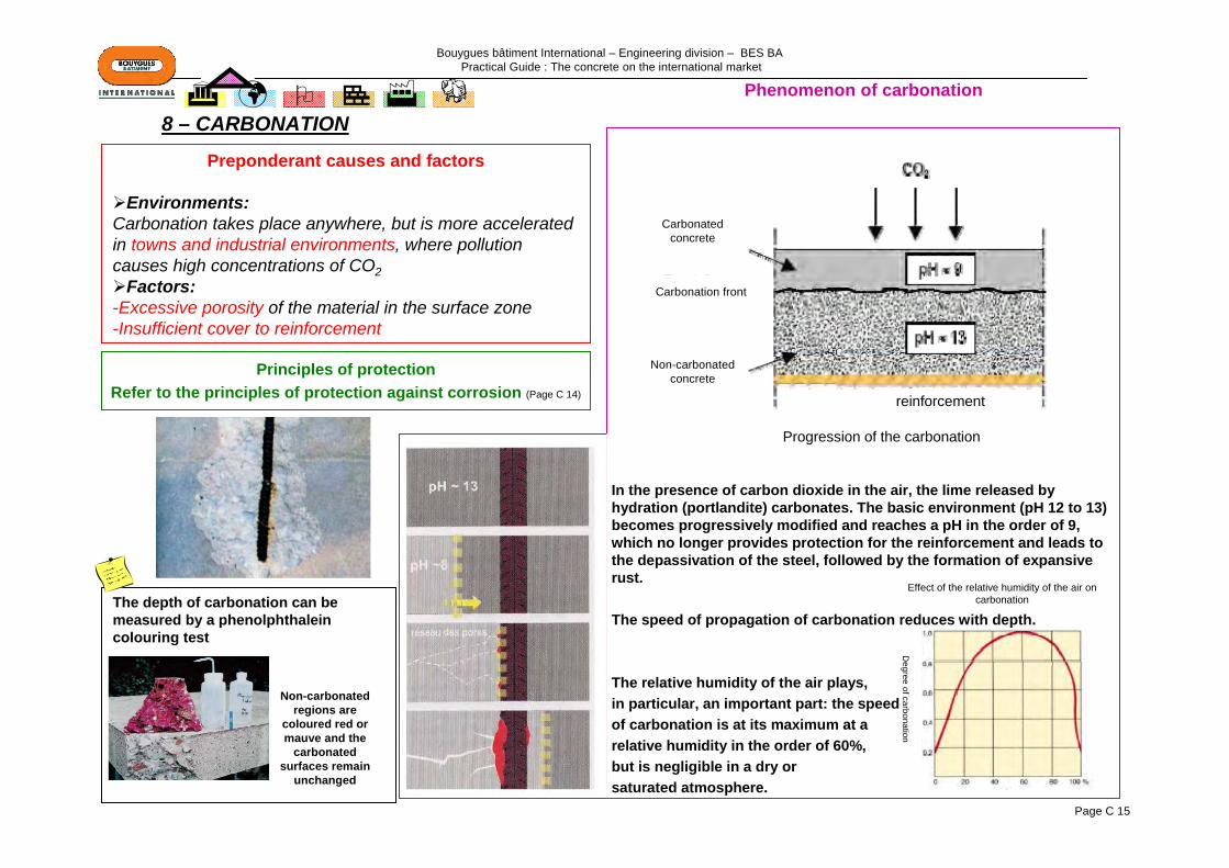
Phenomenon of carbonation
In the presence of carbon dioxide in the air, the lime released by hydration (portlandite) carbonates. The basic environment (pH 12 to 13) becomes progressively modified and reaches a pH in the order of 9, which no longer provides protection for the reinforcement and leads to the depassivation of the steel, followed by the formation of expansive rust.
The speed of propagation of carbonation reduces with depth.
The relative humidity of the air plays,in particular, an important part: the speedof carbonation is at its maximum at arelative humidity in the order of 60%,but is negligible in a dry orsaturated atmosphere.
Preponderant causes and factors
Environments:Carbonation takes place anywhere, but is more accelerated in towns and industrial environments, where pollution causes high concentrations of CO2
Factors:-Excessive porosity of the material in the surface zone -Insufficient cover to reinforcement
The depth of carbonation can be measured by a phenolphthalein colouring test
Principles of protectionRefer to the principles of protection against corrosion (Page C 14)
8 – CARBONATION
Effect of the relative humidity of the air on carbonation
Degree of carbonation
Non-carbonated regions are
coloured red or mauve and the
carbonated surfaces remain
unchanged
Carbonated concrete
Carbonation front
Non-carbonated concrete
reinforcement
Progression of the carbonation
Bouygues bâtiment International – Engineering division – BES BA Practical Guide : The concrete on the international market
Page C 16
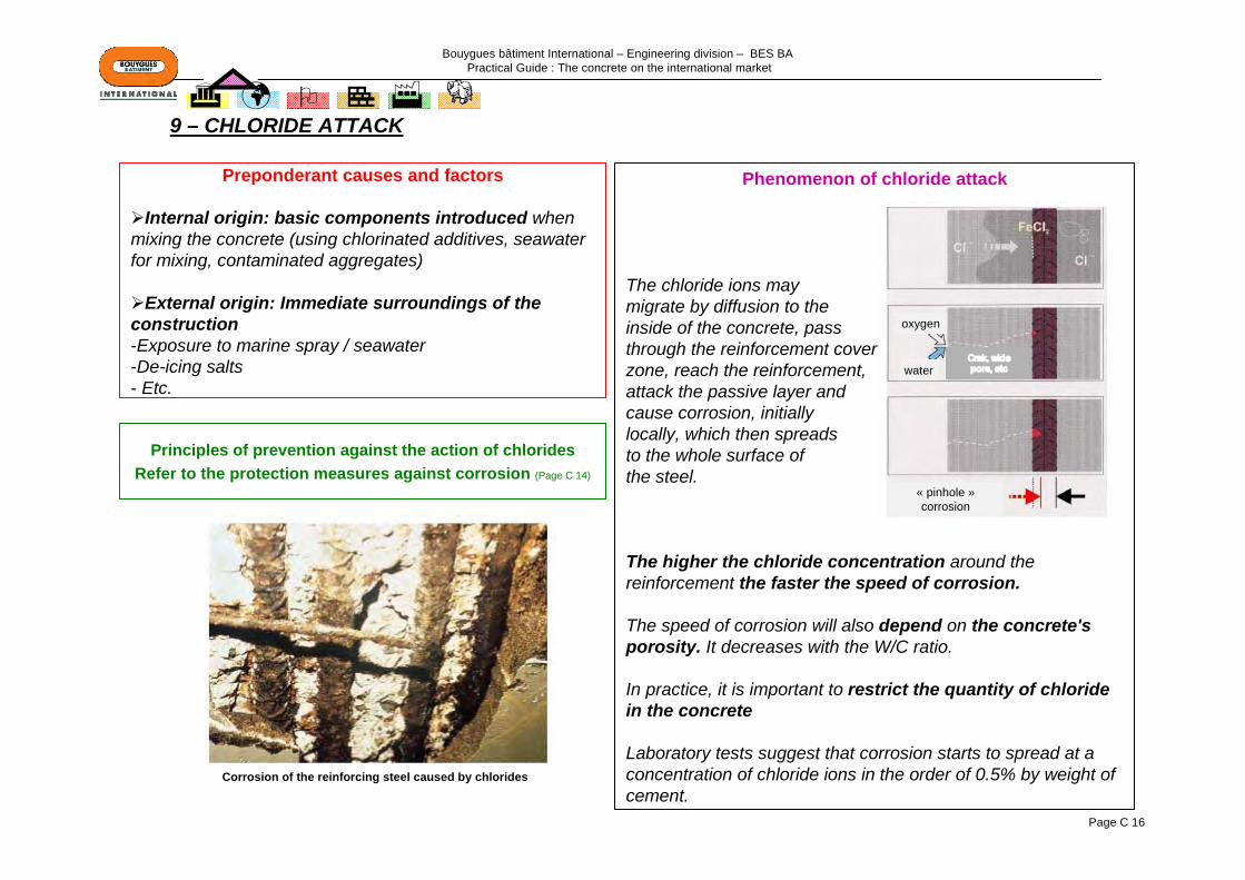
Preponderant causes and factors
Internal origin: basic components introduced when mixing the concrete (using chlorinated additives, seawater for mixing, contaminated aggregates)
External origin: Immediate surroundings of the construction-Exposure to marine spray / seawater-De-icing salts- Etc.
Phenomenon of chloride attack
The chloride ions may migrate by diffusion to the inside of the concrete, pass through the reinforcement cover zone, reach the reinforcement, attack the passive layer and cause corrosion, initially locally, which then spreadsto the whole surface ofthe steel.
The higher the chloride concentration around the reinforcement the faster the speed of corrosion.
The speed of corrosion will also depend on the concrete's porosity. It decreases with the W/C ratio.
In practice, it is important to restrict the quantity of chloride in the concrete
Laboratory tests suggest that corrosion starts to spread at a concentration of chloride ions in the order of 0.5% by weight ofcement.
Principles of prevention against the action of chloridesRefer to the protection measures against corrosion (Page C 14)
9 – CHLORIDE ATTACK
Corrosion of the reinforcing steel caused by chlorides
water
oxygen
« pinhole »corrosion

Bouygues bâtiment International – Engineering division – BES BA Practical Guide : The concrete on the international market
Page C 17
Nature of facing defectsDefects in shape which only affect appearance, are
slight unevenness, inclusions, lack of flatness. Those defects that affect both appearance and durability are major unevenness, chips, spalling, cracks, bruises. In all cases,they result in insufficient protection of the reinforcement
Defects in texture (surface irregularities) which only affect appearance are as follows: slight bubbling, bleeding, orange peeling, crazing, powdering, spalling. On the other hand, major bubbling, porosity, honeycombing and laitance leakage are defects in texture which affect both appearance and durability.
Defects in colour are those to which users are most sensitive. These include the outlines of visible aggregate, black stains, variations in shade, rust stains, marbling, dirt (writing, graffiti), efflorescence, which are evidence of improper use of the concrete.
Principles of preventionConcrete mix: use a compact and low permeability concrete (Page G 12)
Use clean sands and aggregates from uncontaminated sourcesDo not allow excess water to be usedUse specific additives (water reducers, super plasticisers, etc.)
Production and placing of the concreteAdapt the mixing to the compositionDo not allow additional water to be addedComply strictly with the specified concrete cover thicknessesCheck the watertightness of the formwork (abutments and props) and its resistance to
hydrostatic thrustDo not allow the concrete to drop too farVibrate so as obtain the best compaction and avoid segregationProtect the fresh concrete from wind, sun and frostFollow the formwork striking cycles
Suitable design of the construction (Page G 25)
Avoid hollows where water can collect or run offTake into account the direction that the facework faces
Preponderant causes and factorsThe most frequent causes of defects in appearance are of 3 orders:
Badly-designed or badly-selected proportions of the concrete's componentsThe formwork (poor choice of materials, sealing, wedging, skin preparation,
striking)The vibration of the concrete (unsuitable frequency, length of time and
application)Other factors, such as the processes and speed of concreting, weather conditions, or the curing of concrete without formwork or once the formwork is struck must not be neglected, but are seen less often as causes of major defects: they are aggravating factors.
10 – SURFACE APPEARANCE
ARCHITECTONICCONCRETE
Page G 19
Bouygues bâtiment International – Engineering division – BES BA Practical Guide : The concrete on the international market
Page C 18
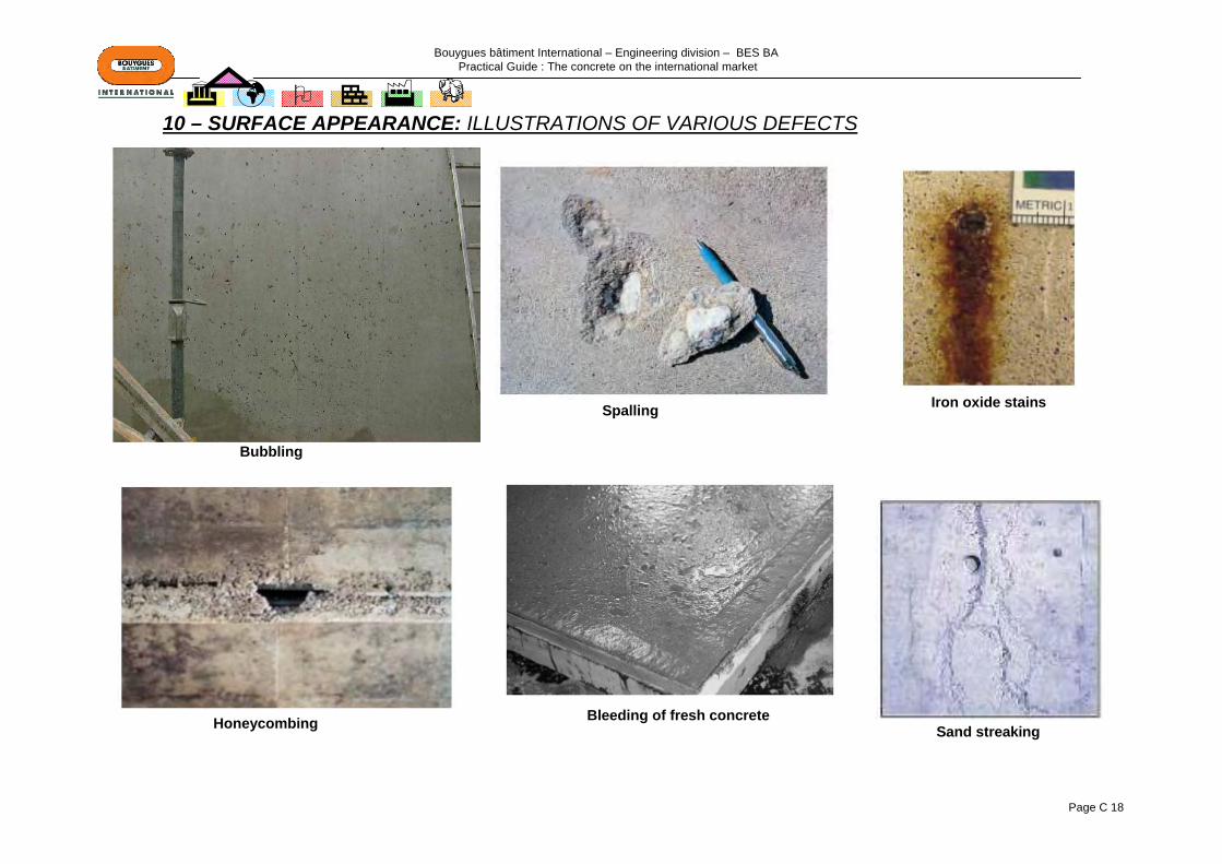
10 – SURFACE APPEARANCE: ILLUSTRATIONS OF VARIOUS DEFECTS
Bubbling
Spalling
Honeycombing Bleeding of fresh concrete
Iron oxide stains
Sand streaking
Bouygues bâtiment International – Engineering division – BES BA Practical Guide : The concrete on the international market
Page C 19
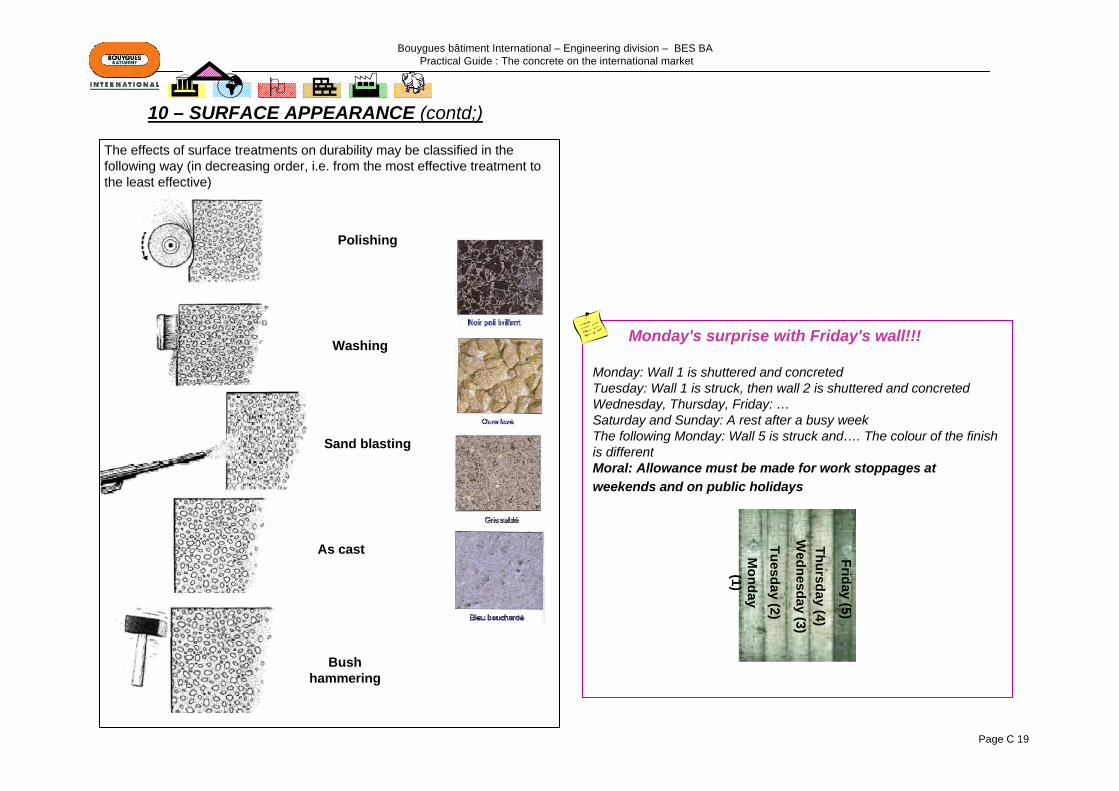
10 – SURFACE APPEARANCE (contd;)
Monday's surprise with Friday's wall!!!
Monday: Wall 1 is shuttered and concretedTuesday: Wall 1 is struck, then wall 2 is shuttered and concretedWednesday, Thursday, Friday: …Saturday and Sunday: A rest after a busy weekThe following Monday: Wall 5 is struck and…. The colour of the finish is differentMoral: Allowance must be made for work stoppages at weekends and on public holidays
Polishing
Washing
Sand blasting
As cast
Bush hammering
Monday (1)
Tuesday (2)
Wednesday (3)
Thursday (4)
Friday (5)
The effects of surface treatments on durability may be classified in the following way (in decreasing order, i.e. from the most effective treatment to the least effective)
Bouygues bâtiment International – Engineering division – BES BA Practical Guide : The concrete on the international market
Page C 20
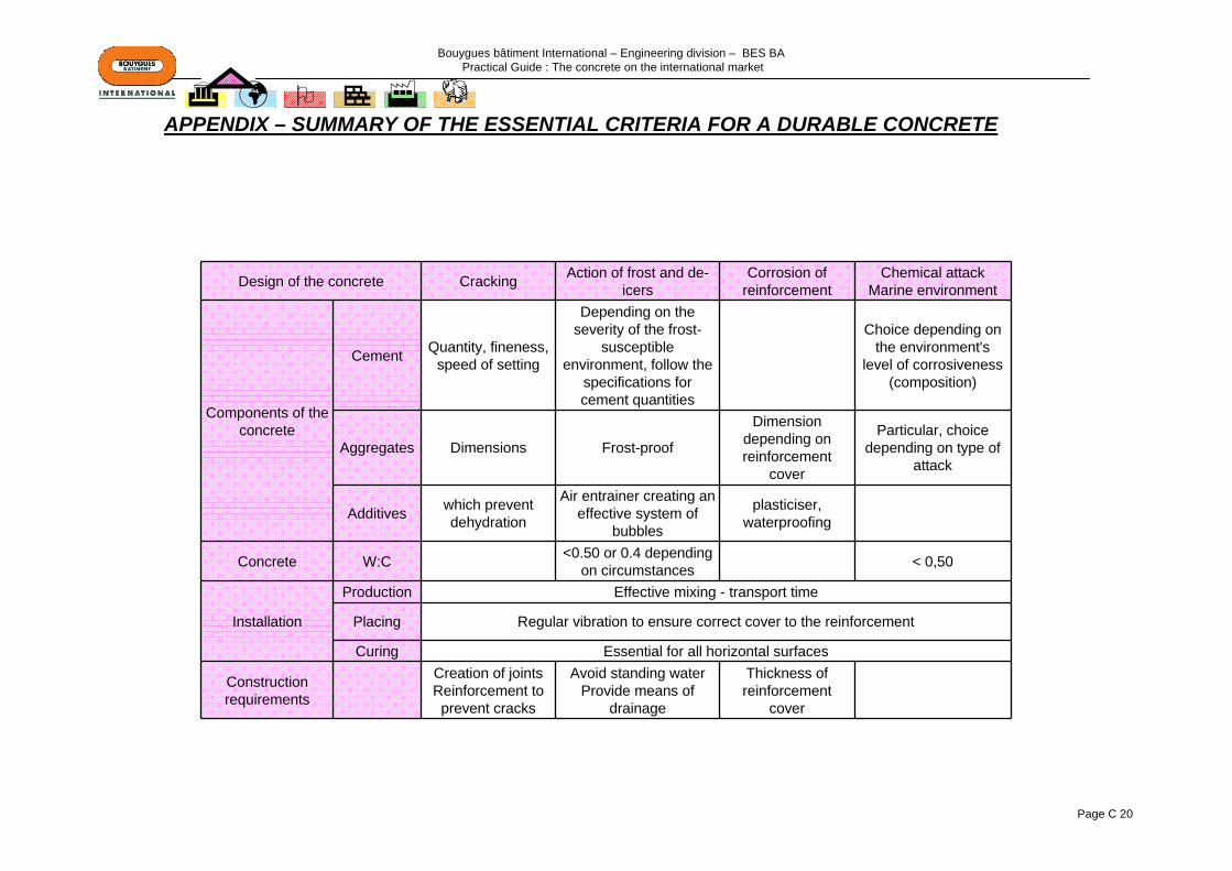
Design of the concrete Cracking Action of frost and de-icers
Corrosion of reinforcement
Chemical attackMarine environment
Components of the concrete
Cement Quantity, fineness, speed of setting
Depending on the severity of the frost-
susceptible environment, follow the
specifications for cement quantities
Choice depending on the environment's
level of corrosiveness (composition)
Aggregates Dimensions Frost-proof
Dimension depending on reinforcement
cover
Particular, choice depending on type of
attack
Additives which prevent dehydration
Air entrainer creating an effective system of
bubbles
plasticiser, waterproofing
Concrete W:C <0.50 or 0.4 depending on circumstances < 0,50
Installation
Production Effective mixing - transport time
Placing Regular vibration to ensure correct cover to the reinforcement
Curing Essential for all horizontal surfaces
Construction requirements
Creation of jointsReinforcement to prevent cracks
Avoid standing waterProvide means of
drainage
Thickness of reinforcement
cover
APPENDIX – SUMMARY OF THE ESSENTIAL CRITERIA FOR A DURABLE CONCRETE
Bouygues bâtiment International – Engineering division – BES BA Practical Guide : The concrete on the international market
Page D 1
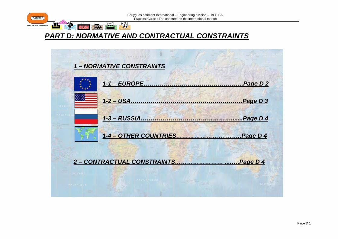
PART D: NORMATIVE AND CONTRACTUAL CONSTRAINTS
1 – NORMATIVE CONSTRAINTS
1-1 – EUROPE…………………………………………..Page D 2
1-2 – USA………………………….…………………….Page D 3
1-3 – RUSSIA……………………………………….......Page D 4
1-4 – OTHER COUNTRIES…………………… ……..Page D 4
2 – CONTRACTUAL CONSTRAINTS…………………… ....….Page D 4
Bouygues bâtiment International – Engineering division – BES BA Practical Guide : The concrete on the international market
Page D 2
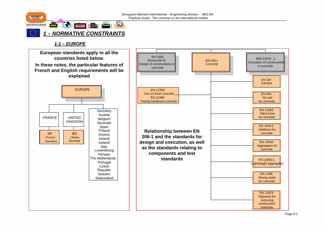
European standards apply in all the countries listed below.
In these notes, the particular features of French and English requirements will be
explained
Relationship between EN 206-1 and the standards for
design and execution, as well as the standards relating to
components and test standards
1-1 – EUROPE
1 – NORMATIVE CONSTRAINTS
EN 206-1Concrete
EN 1992
Design of constructions in concrete
ENV 13670 -1Execution of constructions
in concrete
EN 197Cement
EN 450 Fly ash
for concrete
EN 13263Silica fume
for concrete
EN 1934-2Additives for
concrete
EN 12620Aggregates for
concrete
EN 13055-1Lightweight aggregates
EN 1008Mixing water for concrete
EN 12878Pigments for
colouring construction
materials
EN 12350Test on fresh concrete
EN 12390Testing hardened concrete
FRANCE UNITED KINGDOM
GermanyAustriaBelgiumDenmark
SpainFinlandGreeceIrelandIceland
ItalyLuxembourg
NorwayThe Netherlands-
PortugalCzech
RepublicSweden
Switzerland
EUROPE
NF(French Standard)
BS( British
Standard)
(Eurocode 2)

Bouygues bâtiment International – Engineering division – BES BA Practical Guide : The concrete on the international market
Page D 3
Main standards used for concrete:
-ACI: American Concrete Institute : The ACI develops the majority of the specifications not covered by the IBC.
- ASTM: American Society for Testing Materials: This is the main reference source for ACI as far as specifications of materials and standard tests are concerned.
A specification is a set of characteristics and requirements with which a product, process or service must comply. Specifications are not standards.
1-2 – USA
CODESUntil 1997, there were 3 main « model » codes used in the USA (UBC, SBC et NBC) In 1997, these 3 codes have been grouped
in one code, the IBC : International Building Code.Although, even to day, the 3 model codes are still in use.
STANDARDSThe codes are heavily making reference to Standards such as the
one published by ASTM and ACI or ANSI (American National Standard Institute) and NFPA (National Fire Protection
Association)
Note : ANSI coordinates the development and the use of the various codes and standards used in the USA and represents the
USA in the international standard organizations (ISO)

Bouygues bâtiment International – Engineering division – BES BA Practical Guide : The concrete on the international market
Page D 4
Russian standards relating to concrete components and test standards are grouped together in the GOST
1-3 – RUSSIA
Allowance must be made for the relevant standards in each country and for the political, historical and economic influences of other countries on these relevant standards (for example: Turkmen standards are very close to Russian standards; Hong Kong and Singapore use British standards, which may be supplemented, etc.)
Allowance must be made for contractual constraints, which may require additional specifications. They may sometimes be more restrictive than local standards, whether in respect of the durability of the concrete, seismic constraints, the quality of facework, permissible deformation, etc.
1-4 – OTHER COUNTRIES
2 – CONTRACTUAL CONSTRAINTS
Bouygues bâtiment International – Engineering division – BES BA Practical Guide : The concrete on the international market
Page E 1
Part E: MATERIALS AND CONCRETE
1 – AGGREGATES………………………………………………………………...Page E 2
2 – CEMENT……………………………………………………………………….Page E 12
3 – ADDITIVES…………………………………………………………………….Page E 26
4 – MIXING WATER……………………………………………………………….Page E 34
5 – CONCRETE………………………………………………………………..….Page E 35
6 – CHECKS ON CONCRETE: MAIN NORMATIVE TEXTS………………...Page E 50
APPENDIX – MAIN WORLDWIDE MATERIALS SUPPLIERS………………Page E 54

Bouygues bâtiment International – Engineering division – BES BA Practical Guide : The concrete on the international market
Page E 2
1 - AGGREGATES
1-1 – MINERALOGICAL NATURE …………………………………..Page E 3
1-2 – HIGH SULPHATE, SULPHIDE, CHLORINE CONTENT ……Page E 4
1-3 – SHAPE OF THE GRAINS…………………………………….....Page E 5
1-4 – GRANULARITY………………………………………………….Page E 6
1-5 – CLEANLINESS OF THE AGGREGATES………………………Page E 7
1-6 – WATER AND POROSITY……………………………………...…..Page E 8
APPENDIX 1 – SELECTION CRITERIA DEPENDING ON THE USE OF THE CONCRETE… Page E 9
APPENDIX 2 – MAIN NORMATIVE REFERENCES ………………………………………..……Page E 10

Bouygues bâtiment International – Engineering division – BES BA Practical Guide : The concrete on the international market
Page E 3
Mineralogical origin Properties Difficulties
encounteredPossibility of use for
concrete
Eruptive or magmatic rocks: volcanic and plutonic rocks
GranitesHard and compact;
good frost resistance
Yes, mostlyDiorites
Porphyrites
BasaltsMetamorphic rocks: this includes any pre-existing
rock
Quartzites Hard and compact; chemical resistant
High quality aggregates used for
faceworkMarbles Yes
Shales Frost-sensitive Existence of friable fines Only hard shales
Gneiss Yes, if stableSedimentary rocks: this covers the surface of the continents and the
bottoms of the oceans
Limestones Good adhesion to mortar Yes
Dolostones Prior tests
Most aggregates are suitable for concrete
Unfavourable influence of clays, marly limestones
(expansion and long-term changes)
3 types of aggregates:•Natural: of mineral origin, obtained from loose or massive rocks, having been subjected to mechanical transformation only•Artificial: of mineral origin resulting from an industrial process including thermal or other transformations •Recycled: obtained by processing an inorganic material previously used in construction, such as concrete from building demolition
Origin of "extraction"•Rolled alluvial aggregates (shape acquired by erosion). For concrete, they are usually siliceous, calcareous or sand-limes•Quarried aggregates of angular shapes (obtained by blasting and crushing). In order to select this type of aggregate, consideration must be given to: the origin of the rock, the regularity of the bed, the degree of crushing, etc.)
1-1– MINERALOGICAL NATURE
MINERALOGICAL NATURE

Bouygues bâtiment International – Engineering division – BES BA Practical Guide : The concrete on the international market
Page E 4
HIGH SULPHATE, SULPHIDE AND
CHLORIDE CONTENT
Reaction with cement, cracking, corrosion of the
reinforcement
Chloride ion content: chlorides modify the kinetics of the hydration of the cement and cause the reinforcement to corrode. The chloride content arising from all the concrete’s components is therefore limited.
Reactivity to alkalis: In unfavourable conditions (aggregates containing a significant fraction of soluble silica in an alkali-rich environment) and in the presence of moisture, alkali reaction phenomena may cause the concrete to expand. (Page C 5)
Sulphur and sulphate content: Aggregates may contain small quantities of sulphates and sulphides (in France: Total sulphur content <0.4% by mass and sulphate content <0.2%).The sulphides present in the aggregates may oxidise and become sulphates, which may lead to expansion phenomena. The sulphates may interfere with setting and with the action of the additives.
1-2 – HIGH SULPHATE, SULPHIDE, CHLORINE CONTENT

Bouygues bâtiment International – Engineering division – BES BA Practical Guide : The concrete on the international market
Page E 5
SHAPE OF THE GRAINS,
ANGULARITY
Certain crushed sands may sometimes
adversely affect the placing of the concrete
and its final compactness.
Granular class: Aggregates are described according to their granular class d/D (where d is the smaller dimension and D the greater dimension). The granular categories are specified by using sets of different-sized sieves (en mm).
Flatness test A: The flatness factor characterises the shape of the aggregate on the basis of its largest dimension and its thickness. The higher the value of A, the more flat elements the gravel contains. A poor shape has an effect on consistence and encourages segregation.
Fineness modulus MF: This is equal to 1/100th of the sum of the cumulative sieve oversize, expressed in %, on various sieves. The lower the fineness modulus, the finer the sand.
Fines: D ≤ 0.063 mm
Sands: D ≤ 4 mmGravels: d ≥ 2 mm and D ≥ 4 mm
1-3 – SHAPE OF THE GRAINS, ANGULARITY
Influence of the granulometric compactness on the compactness of the granular mixture and on the consistence of the concrete
1 – Gravel dominant: the high level of friction forces reduces consistence2 – Maximum compactness: Consistence close to optimum3 – Sand dominant: The high quantity of water required for dampening leads to a reduction of consistence
Gravel
Sand
Bouygues bâtiment International – Engineering division – BES BA Practical Guide : The concrete on the international market
Page E 6
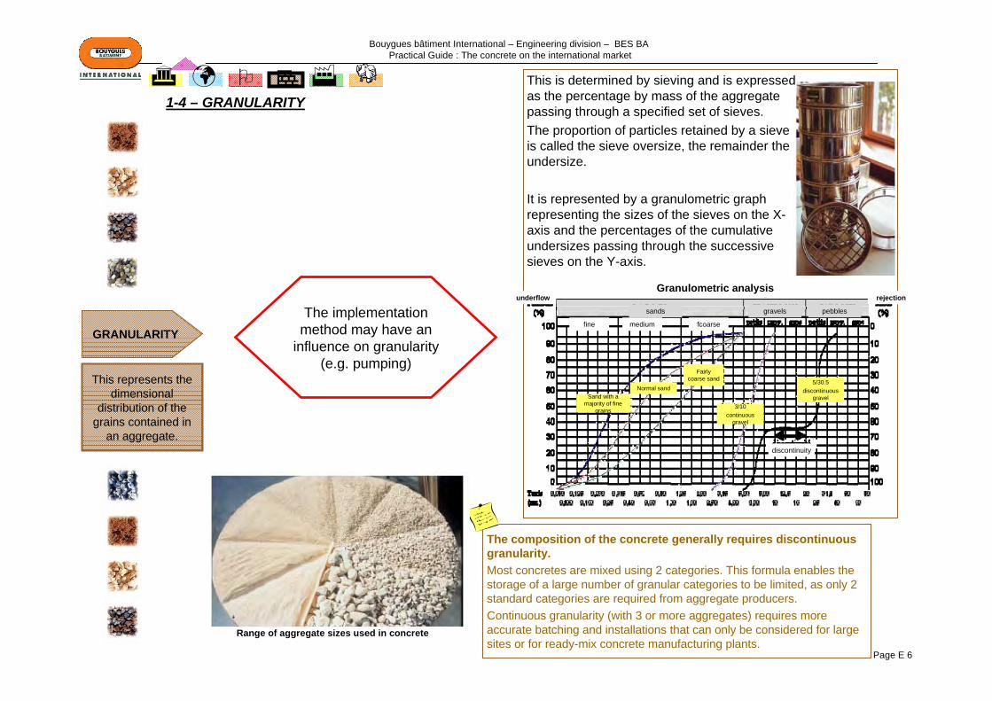
This is determined by sieving and is expressed as the percentage by mass of the aggregate passing through a specified set of sieves. The proportion of particles retained by a sieve is called the sieve oversize, the remainder the undersize.
It is represented by a granulometric graph representing the sizes of the sieves on the X-axis and the percentages of the cumulative undersizes passing through the successive sieves on the Y-axis.
GRANULARITY
This represents the dimensional
distribution of the grains contained in
an aggregate.
The implementation method may have an
influence on granularity (e.g. pumping)
The composition of the concrete generally requires discontinuousgranularity.Most concretes are mixed using 2 categories. This formula enables the storage of a large number of granular categories to be limited, as only 2 standard categories are required from aggregate producers.Continuous granularity (with 3 or more aggregates) requires moreaccurate batching and installations that can only be considered for large sites or for ready-mix concrete manufacturing plants.
1-4 – GRANULARITY
Range of aggregate sizes used in concrete
Sand with a majority of fine
grains
Normal sand
Fairly coarse sand
3/10 continuous
gravel
5/30.5discontinuous
gravel
Granulometric analysisunderflow
sands gravels pebbles
rejection
fine medium fcoarse
discontinuity

Bouygues bâtiment International – Engineering division – BES BA Practical Guide : The concrete on the international market
Page E 7
For gravel: Given by the percentage passing through a 0.5 mm sieve (sieving carried out under water)
For sands: Provided by the "sand equivalent test" which enables the proportion of clay in the material to be measured. The higher the SE (cleanliness) value, the cleaner the sand
This may also be evaluated by the methylene blue test(VB). The lower the VB value, the cleaner the sands.
CLEANLINESSOF AGGREGATES
Cleanliness refers to an absence of
undesirable fine elements (e.g:
clayey fines) in the aggregates
Impurities interfere with the hydrationof the cement and cause
defects in aggregate / paste adhesion, which may have an
effect on the strength of the concrete
1-5– CLEANLINESS OF THE AGGREGATES
Clean sandPS = 93 PS = 78
Polluted sandPS = 53
H1 = 7.3
H2 = 7.8
H1 = 7.2
H2 = 9.2
H1 = 8
H2 = 15
Water Flocculate Sand

Bouygues bâtiment International – Engineering division – BES BA Practical Guide : The concrete on the international market
Page E 8
Apparent density: mass of dry aggregate occupying the unit of volume. It depends on the settlement of the grains. Example: rolled calcareous silicate aggregates- Apparent: ~ 1400 to 1600 kg/m3
- Absolute (excluding voids between grains): 2500 to 2600 kg/m3
Porosity: represents the ratio of the volume of voids contained in the grains to the volume of the grains, as a percentage. The porosity of typical aggregates is generally very low. It is high in the case of lightweight aggregates.
Water absorption factor Ab: represents the water absorption capacity of an aggregate. The higher it is, the more absorbent the material is.
WATER AND POROSITY
The water content of aggregates stored on site must be known, in order to calculate the amount
of water to be added when the concrete is
mixed.
Sands expand (increase in volume reaching up to 20 to 25%) at water contents of 4 to 5%. The quantity, if calculated by volume, must be corrected.
1-6 – WATER AND POROSITY

Bouygues bâtiment International – Engineering division – BES BA Practical Guide : The concrete on the international market
Page E 9
Nature of the concretes and of the construction Nature of the aggregates Density of the
concrete
Traditional concrete for site or prefabrication plant
All rolled or crushed aggregates, with a preference for siliceous, calcareous
or sand-limes
2200 to 2400 kg/m3
Exposed, architectonic concrete
The same, but also porphyrites, basalts, granites, diorites, which
provide a very rich palette of appearances and colours
2200 to 2400 kg/m3
Road uses All of rolled or crushed origins 2200 to 2300 kg/m3
Lightweight
concretes
for structures Expanded clay or shale, expanded slag
1500 to 1800 kg/m3
semi-insulatingsemi-load-
bearingExpanded clay, pozzolana, pumice 1000 to 1500
kg/m3
Insulating Vermiculite, cork, timber, expanded polystyrene, expanded glass 300 to 800 kg/m3
Dense concrete Corundum, barytine, magnetite 3000 to 5000 kg/m3
Refractory concrete Corundum, refractory product waste, special aggregates
2200 to 2500 kg/m3
Concrete or screeds for industrial slabs
(subject to high abrasion)
Corundum, carborundum, metal aggregates
2400 to 3000 kg/m3
APPENDIX 1 – SELECTION CRITERIA DEPENDING ON THE USE OF THE CONCRETE

Bouygues bâtiment International – Engineering division – BES BA Practical Guide : The concrete on the international market
Page E 10
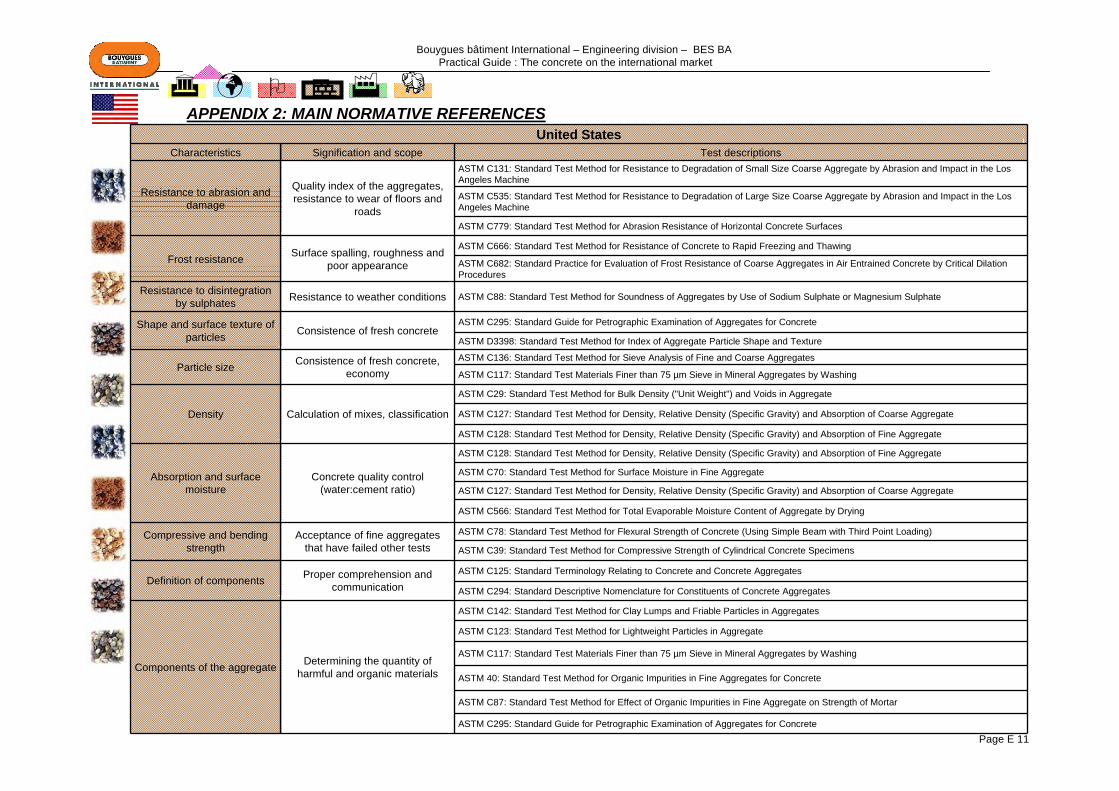
APPENDIX 2: MAIN NORMATIVE REFERENCES
French standards British standards
NF EN 12630: Aggregates for concrete BS EN 12620: Aggregates for concrete
NF EN 1305-1: Lightweight aggregates - part 1: lightweight aggregates for concrete and mortar
BS EN 13055-1: Lightweight aggregates - Part 1: Lightweight aggregates for concrete, mortar and grout
XP P 18-545: Aggregates: elements for definition, conformity and codification
PD 6682-1: Aggregates - Part 1: Aggregates for concrete Guidance on the use of BS EN 12620
Series NF EN 933: Tests to determine the geometric characteristics of aggregates
PD 6682-4: Aggregates - Part 4: Lightweight aggregates for concrete, mortar and grout Guidance on the use of BS EN 13055-1
Series NF EN 1097: Tests to determine the mechanical and physical characteristics of aggregatesSeries NF EN 1744: Tests relating to the chemical properties of aggregates
Russian standards
GOST 5578: Slag crushed stone and slag sand of ferrous and non ferrous metallurgy for concretes. Specifications
GOST 8267: Crushed stone of rocks and gravel for construction works. Specifications
GOST 8735: Sand for construction work. Testing method
GOST 8736: Sand for construction work. Specifications
Bouygues bâtiment International – Engineering division – BES BA Practical Guide : The concrete on the international market
Page E 11
United StatesCharacteristics Signification and scope Test descriptions
Resistance to abrasion and damage
Quality index of the aggregates, resistance to wear of floors and
roads
ASTM C131: Standard Test Method for Resistance to Degradation of Small Size Coarse Aggregate by Abrasion and Impact in the Los Angeles Machine
ASTM C535: Standard Test Method for Resistance to Degradation of Large Size Coarse Aggregate by Abrasion and Impact in the Los Angeles Machine
ASTM C779: Standard Test Method for Abrasion Resistance of Horizontal Concrete Surfaces
Frost resistance Surface spalling, roughness and poor appearance
ASTM C666: Standard Test Method for Resistance of Concrete to Rapid Freezing and Thawing
ASTM C682: Standard Practice for Evaluation of Frost Resistance of Coarse Aggregates in Air Entrained Concrete by Critical Dilation Procedures
Resistance to disintegration by sulphates Resistance to weather conditions ASTM C88: Standard Test Method for Soundness of Aggregates by Use of Sodium Sulphate or Magnesium Sulphate
Shape and surface texture of particles Consistence of fresh concrete
ASTM C295: Standard Guide for Petrographic Examination of Aggregates for Concrete
ASTM D3398: Standard Test Method for Index of Aggregate Particle Shape and Texture
Particle size Consistence of fresh concrete, economy
ASTM C136: Standard Test Method for Sieve Analysis of Fine and Coarse Aggregates
ASTM C117: Standard Test Materials Finer than 75 µm Sieve in Mineral Aggregates by Washing
Density Calculation of mixes, classification
ASTM C29: Standard Test Method for Bulk Density ("Unit Weight") and Voids in Aggregate
ASTM C127: Standard Test Method for Density, Relative Density (Specific Gravity) and Absorption of Coarse Aggregate
ASTM C128: Standard Test Method for Density, Relative Density (Specific Gravity) and Absorption of Fine Aggregate
Absorption and surface moisture
Concrete quality control (water:cement ratio)
ASTM C128: Standard Test Method for Density, Relative Density (Specific Gravity) and Absorption of Fine Aggregate
ASTM C70: Standard Test Method for Surface Moisture in Fine Aggregate
ASTM C127: Standard Test Method for Density, Relative Density (Specific Gravity) and Absorption of Coarse Aggregate
ASTM C566: Standard Test Method for Total Evaporable Moisture Content of Aggregate by Drying
Compressive and bending strength
Acceptance of fine aggregates that have failed other tests
ASTM C78: Standard Test Method for Flexural Strength of Concrete (Using Simple Beam with Third Point Loading)
ASTM C39: Standard Test Method for Compressive Strength of Cylindrical Concrete Specimens
Definition of components Proper comprehension and communication
ASTM C125: Standard Terminology Relating to Concrete and Concrete Aggregates
ASTM C294: Standard Descriptive Nomenclature for Constituents of Concrete Aggregates
Components of the aggregate Determining the quantity of harmful and organic materials
ASTM C142: Standard Test Method for Clay Lumps and Friable Particles in Aggregates
ASTM C123: Standard Test Method for Lightweight Particles in Aggregate
ASTM C117: Standard Test Materials Finer than 75 µm Sieve in Mineral Aggregates by Washing
ASTM 40: Standard Test Method for Organic Impurities in Fine Aggregates for Concrete
ASTM C87: Standard Test Method for Effect of Organic Impurities in Fine Aggregate on Strength of Mortar
ASTM C295: Standard Guide for Petrographic Examination of Aggregates for Concrete
APPENDIX 2: MAIN NORMATIVE REFERENCES

Bouygues bâtiment International – Engineering division – BES BA Practical Guide : The concrete on the international market
Page E 12
2 - CEMENTS2-1 – MANUFACTURE OF A CEMENT ………………………………………..…….Page E 13
2-2 – HYDRATION REACTION OF THE CEMENT ……………………………..….Page E 14
2-3 – EUROPE – EN 197-1 2-3-1 – Description of a typical cement ………………………………..Page E 152-3-2 – Additions…………………………………………………………….Page E 162-3-3 – French specifications .....………………………………………...Page E 172-3-4 – British specifications .....………………………………………..Page E 192-3-5 – Main European normative texts ………………………………..Page E 20
2-4 – USA2-4-1 – ASTM C150: Specification for Portland cement………………Page E 212-4-2 – ASTM C595: Specification for Blended Hydraulic cement….Page E 222-4-3 – ASTM C1157: Standard performance for hydraulic cement..Page E 222-4-4 – Summary table ………………………………………...…………...Page E 222-4-5 – SMC: Supplementary Cementitious Materials………………...Page E 23
2-5 – IMPORTANT NOTE: EUROPE / USA………………………………………..….Page E 24
2-6 – RUSSIA: MAIN NORMATIVE TEXTS RELATING TO CEMENTS ................Page E 25
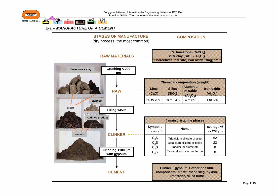
Bouygues bâtiment International – Engineering division – BES BA Practical Guide : The concrete on the international market
Page E 13
80% limestone (CaCO3)20% clay (SiO2 – Al2O3)
Correctives: bauxite, iron oxide, slag, etc.
1 to 6%4 to 8%18 to 24%65 to 70%
Iron oxide(Al2O3)
Aluminium oxide(Al2O3)
Silica(SiO2)
Lime(CaO)
Chemical composition (weight)
62 2288
Tricalcium silicate or aliteDicalcium silicate or belite
Tricalcium aluminate Tetracalcium aluminoferrite
C3SC2SC3SC4S
average % by weight NameSymbolic
notation
4 main cristalline phases
Clinker + gypsum + other possible components: blastfurnace slag, fly ash,
limestone, silica fume
RAW MATERIALS
RAW
CLINKER
CEMENT
STAGES OF MANUFACTURE(dry process, the most common)
COMPOSITION
Crushing < 200 µm
Firing 1450°
Grinding <100 µm with gypsum
2-1 – MANUFACTURE OF A CEMENT
Limestone + clay
Additive product
gypsum
cement

Bouygues bâtiment International – Engineering division – BES BA Practical Guide : The concrete on the international market
Page E 14
2-2 – HYDRATION REACTION OF THE CEMENT
Water/cement ratioThe quantity of water is characterised by the water: cement ratio. The higher this ratio, the longer hydration will take and theweaker and less durable the concrete will be. However, the quantity of water can be greatly reduced if the concrete is heavily compacted and, especially, if plasticisers (water reducers) or super-plasticisers (significant water reduction) are used.When calculating quantities for the mix, the terms water: binder ratio (this is the mass of the water divided by that of the binders –Portland cement, composite cement, fly ash, slag, silica fume,, etc.) and water: cement ratio are often used indifferently to describe the proportion by weight of the water and the Portland cement or of the water and the composite cement.
The water forms a system of capillaries around the grains
Formation of tobermorite gel on the surface of grains
The capillary interstice reduce. Appearance of a certain stiffness of the
paste
The interstices are partially filled by the gel. The paste acquires strength
Strength continues to grow for as long as the gel continues to develop. Slow phenomenon and presence of water
necessary
Before setting
During mixing water
setting
Start of hardening
Subsequent hardening
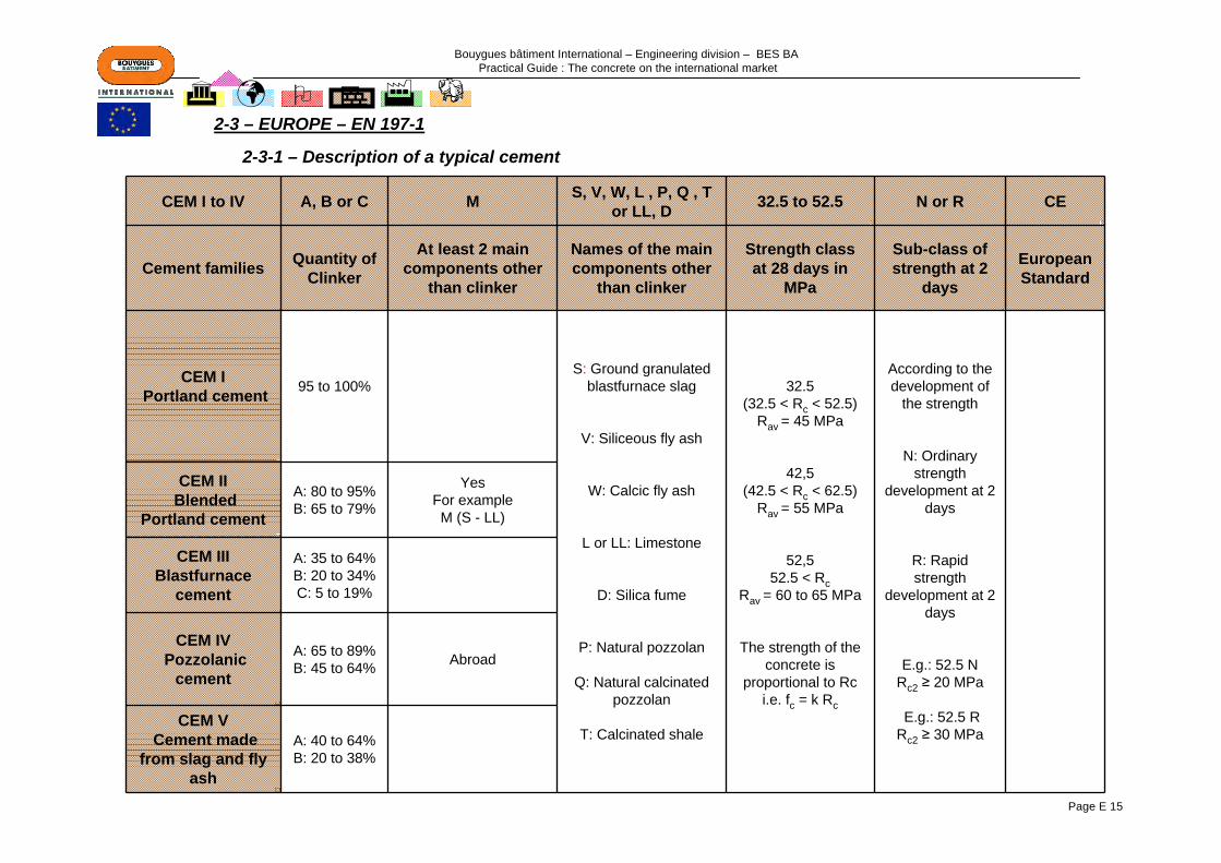
Bouygues bâtiment International – Engineering division – BES BA Practical Guide : The concrete on the international market
Page E 15
CEM I to IV A, B or C M S, V, W, L , P, Q , T or LL, D 32.5 to 52.5 N or R CE
Cement families Quantity of Clinker
At least 2 main components other
than clinker
Names of the main components other
than clinker
Strength class at 28 days in
MPa
Sub-class of strength at 2
days
EuropeanStandard
CEM IPortland cement 95 to 100%
S: Ground granulatedblastfurnace slag
V: Siliceous fly ash
W: Calcic fly ash
L or LL: Limestone
D: Silica fume
P: Natural pozzolan
Q: Natural calcinated pozzolan
T: Calcinated shale
32.5(32.5 < Rc < 52.5)
Rav = 45 MPa
42,5(42.5 < Rc < 62.5)
Rav = 55 MPa
52,552.5 < Rc
Rav = 60 to 65 MPa
The strength of the concrete is
proportional to Rc i.e. fc = k Rc
According to the development of
the strength
N: Ordinary strength
development at 2 days
R: Rapid strength
development at 2 days
E.g.: 52.5 NRc2 ≥ 20 MPa
E.g.: 52.5 RRc2 ≥ 30 MPa
CEM IIBlended
Portland cement
A: 80 to 95%B: 65 to 79%
YesFor example M (S - LL)
CEM IIIBlastfurnace
cement
A: 35 to 64%B: 20 to 34%C: 5 to 19%
CEM IVPozzolanic
cement
A: 65 to 89%B: 45 to 64% Abroad
CEM VCement made
from slag and fly ash
A: 40 to 64%B: 20 to 38%
2-3 – EUROPE – EN 197-1
2-3-1 – Description of a typical cement

Bouygues bâtiment International – Engineering division – BES BA Practical Guide : The concrete on the international market
Page E 16
Main effects of the components added to the clinker
Components added
Main effects of the component added to the clinker
SGround
granulated blastfurnace slag
Reduces short-term reactivity. Reduces shrinkage.Slower increase in strengthSuitable for constructions in contact with the ground
P Natural pozzolanaReduces short-term reactivity and its effects Supplements hydration by consuming Portlandite
Q Calcinated pozzolana
V Siliceous fly ashProvides additional long-term strengthImproves durability by reducing permeabilityImproves consistence. Stains the concrete black
W Calcic fly ash Improves consistence. Stains the concrete black
T Calcinated shale Reduces short-term reactivity and its effects Supplements hydration by consuming Portlandite
L and LL Ground limestone
Accelerates the very short-term (2 to 7 days) kineticsSupplements the granular skeleton
M Mixture of components
Combines the effects of the various componentsReduces the price of the cement. Variable colour and properties
2-3-2 – Additives
From left to right: fly ash, metakaolin (calcinated clay), silica fume, fly ash, slag and calcinated shale

Bouygues bâtiment International – Engineering division – BES BA Practical Guide : The concrete on the international market
Page E 17
Main cements marketed in France
Main fields of use Particular precautions
CEM I
Reinforced or Prestressed Concrete CEM I category R: Rapid striking of formwork (prefabrication)CEM I 52.5N or 52.5R: High strength RC or PC Mechanical characteristics not suitable for standard masonry, mass concrete or lightly reinforced concrete
to be avoided for mass concrete construction due to the heat of hydration (excessive rise in temperature during execution)Caution if high risk of alkali reaction
CEM II
Suitable for mass concrete requiring a moderate rise in temperature.Category R: Works requiring higher initial strengthPM or ES: Works in corrosive environmentsCEM II 32.5: Masonry worksCEMII 32.5N and 42.5N: Any type of RC workCEM II 52.5: RC or PC
Caution if attractive appearance is important: Certain CEM II cements contain high proportions of components likely to cause very wide variations in colour, particularly fly ash.
CEM II/ A-S or B-
SCEM IIICEM V
Blastfurnace slag cements suitable for:- Hydraulic or underground construction, foundations, injection- Works in corrosive water: sea, selenitic, industrial and pure water; - Mass concrete works: foundations and dams- Works in an agricultural environment: storage, slurry and silage pits
Concretes (using these types of cement) that are liable to desiccation: keep damp during setting (curing and curing products); to be avoided for rendersDo not use this type of cement in cold weather as hydration slows down in the coldCEM V: take care when mixing with the additives.
For special works, use cements that have additional characteristics:In corrosive environments:
Cements for works in the sea (PM)Cements for works in water with a high sulphate content (ES)
For mass concrete construction: Cements with a low initial hydration heat (CP)
2-3-3 – French specifications
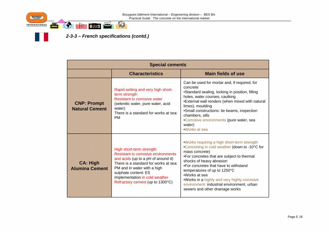
Bouygues bâtiment International – Engineering division – BES BA Practical Guide : The concrete on the international market
Page E 18
Special cements
Characteristics Main fields of use
CNP: Prompt Natural Cement
Rapid setting and very high short-term strengthResistant to corrosive water(selenitic water, pure water, acid water)There is a standard for works at sea: PM
Can be used for mortar and, if required, for concrete•Standard sealing, locking in position, filling holes, water courses, caulking•External wall renders (when mixed with natural limes), moulding•Small constructions: tie beams, inspection chambers, sills•Corrosive environments (pure water, sea water)•Works at sea
CA: High Alumina Cement
High short-term strengthResistant to corrosive environments and acids (up to a pH of around 4)There is a standard for works at sea: PM and in water with a high sulphate content: ESImplementation in cold weatherRefractory cement (up to 1300°C)
•Works requiring a high short-term strength•Concreting in cold weather (down to -10°C for mass concrete)•For concretes that are subject to thermal shocks of heavy abrasion•For concretes that have to withstand temperatures of up to 1250°C•Works at sea•Works in a highly and very highly corrosive environment: industrial environment, urban sewers and other drainage works
2-3-3 – French specifications (contd.)

Bouygues bâtiment International – Engineering division – BES BA Practical Guide : The concrete on the international market
Page E 19
Main cements marketed in the United Kingdom
Description Notation
Portland Cement I
Sulphate-resistant Portland cement SRPC
Portland cement + another component (Fly ash, ground granulated blastfurnace slag (GGBS), limestone) IIA
Portland cement + 21 to 35% of fly ash IIB-V or IIB-V+SR
Portland cement + 21 to 35% of GGBS IIB-S
Portland cement + 36 to 65% of GGBS III-A
Portland cement + 66 to 80% of GGBS IIIB or IIIB+SR
Portland cement + 36 to 55% of fly ash IVB or IVB+SR
Other cements for special uses:Sulphate-resistant cements: BS 4027 – Specification for sulphate-resisting Portland cement (SRPC)
Cements with low hydration heat: BS 1370 – Specification for low-heat Portland cement
2-3-4 – British specifications
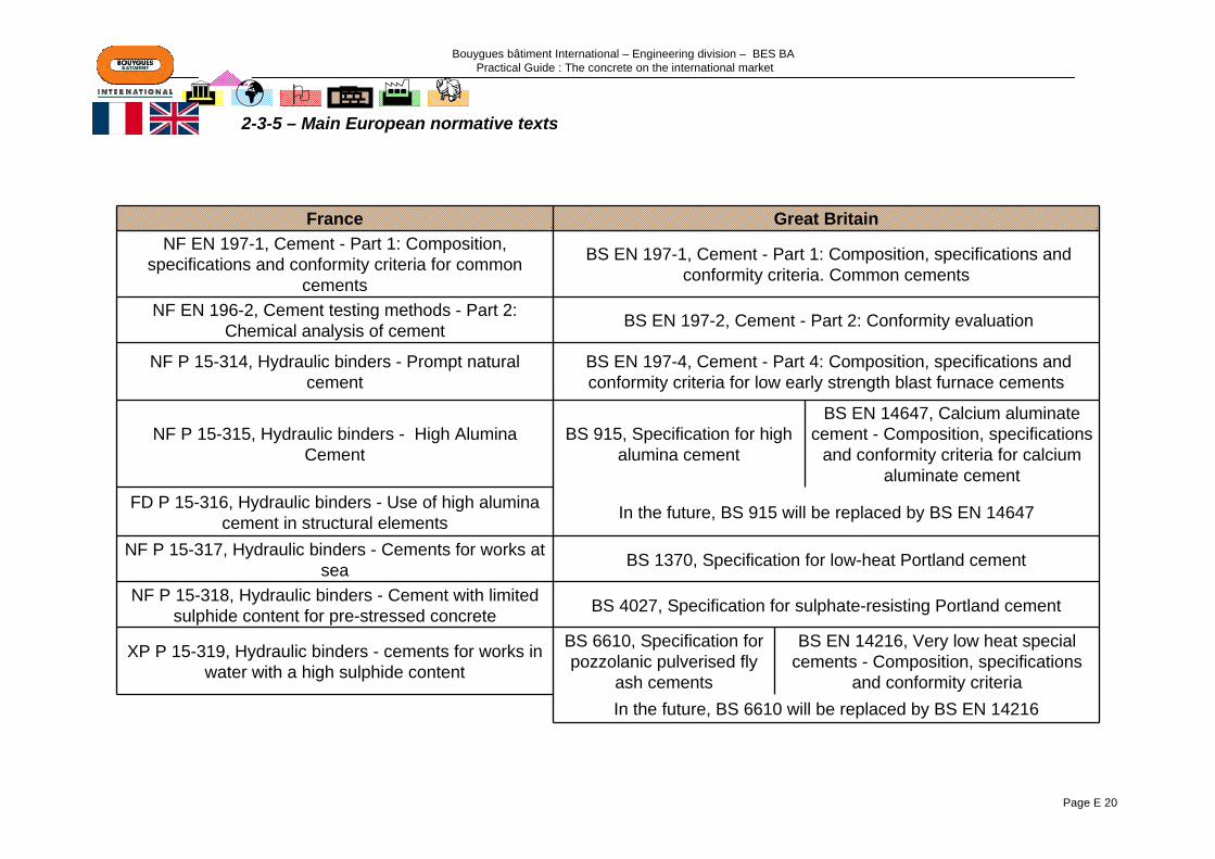
Bouygues bâtiment International – Engineering division – BES BA Practical Guide : The concrete on the international market
Page E 20
2-3-5 – Main European normative texts
France Great BritainNF EN 197-1, Cement - Part 1: Composition,
specifications and conformity criteria for common cements
BS EN 197-1, Cement - Part 1: Composition, specifications and conformity criteria. Common cements
NF EN 196-2, Cement testing methods - Part 2: Chemical analysis of cement BS EN 197-2, Cement - Part 2: Conformity evaluation
NF P 15-314, Hydraulic binders - Prompt natural cement
BS EN 197-4, Cement - Part 4: Composition, specifications and conformity criteria for low early strength blast furnace cements
NF P 15-315, Hydraulic binders - High Alumina Cement
BS 915, Specification for high alumina cement
BS EN 14647, Calcium aluminate cement - Composition, specifications
and conformity criteria for calcium aluminate cement
FD P 15-316, Hydraulic binders - Use of high alumina cement in structural elements In the future, BS 915 will be replaced by BS EN 14647
NF P 15-317, Hydraulic binders - Cements for works at sea BS 1370, Specification for low-heat Portland cement
NF P 15-318, Hydraulic binders - Cement with limited sulphide content for pre-stressed concrete BS 4027, Specification for sulphate-resisting Portland cement
XP P 15-319, Hydraulic binders - cements for works in water with a high sulphide content
BS 6610, Specification for pozzolanic pulverised fly
ash cements
BS EN 14216, Very low heat special cements - Composition, specifications
and conformity criteriaIn the future, BS 6610 will be replaced by BS EN 14216

Bouygues bâtiment International – Engineering division – BES BA Practical Guide : The concrete on the international market
Page E 21
Specifications for cements in the USA are dictated by ASTM (American Society for Testing and Materials) standards, the main ones of which are:-ASTM C 150: Specification for Portland Cement-ASTM C 595: Specification for Blended Hydraulic Cement-ASTM C 1157: Standard Performance Specification for Hydraulic Cement These standards make a distinction between Portland cements and blended cements
Cements meeting ASTM C 150 are the most widely-available from cement manufacturers.It sets the physical and chemical characteristics to be met by the 5 types of Portland cement.This ASTM standard sets the content of the 4 main components of cement (C3S, C2S, C3A, C4AF, and composition of the clinker).
Type of cement Particular features
I General useII Moderate hydration heat and sulphate-resistanceIII High initial strengthIV Low hydration heatV High sulphate-resistance
IA, IIA or IIA Type I, II or III with air entrainerLA With low alkali contentI/II Mix of types I and II, but not referenced by ASTM
This ASTM standard only permits additions of calcium sulphate and air-entraining agents to the cements. Other additives may be used; their specifications are set out in standard C 495, which sets the permissible deviations in the properties of the cements in the event of addition.
2-4 – USA
2-4-1 – ASTM C150: Specification for Portland Cement

Bouygues bâtiment International – Engineering division – BES BA Practical Guide : The concrete on the international market
Page E 22
Contrary to the previous ASTM standards, which specify the composition of the various cements, this standard is based solely on the characteristics and the levels of performance of the cements. It therefore imposes no restrictions on their composition.There are 6 different types: GU, HE, MS, HS, LH, MH (see table)
General useModerate sulphate-resistance
Early strength Low hydration heat
Moderate hydration heat
High sulphate-resistance
With low alkali content
Portland CementASTM C150 I
II (sulphate-resistance as an
option)III IV II V LA as an option
Blended Hydraulic CementsASTM C505
ISIP, PI(PM)I(SM)
S
IS(MH)IP(MH)
I(PM)(MH)I(SM)(MH)
P(LH)
IS(MS)IP(MS)P(MS)
I(PM)(MS)I(SM)(MS)
LA as an option
Hydraulic cementsASTM C1157 GU MH HE LH MS HS Option R
These cements are much more widely-used in Europe. They are, however, gaining popularity in the USAThe American standard permits the use of pozzolan and slag in blended cements, provided thatthe specifications for pozzolanic activity are met(see table). In particular, the compressive strength of the blended cement must reach at least 75% of that of the reference Portland cement. This standard also specifiesthe physical and chemical specifications for the blendedcements. In addition, all these types of cement may be treatedto meet criteria: moderatesulphate-resistance (MS), air-entrainment (A), hydrationheat moderate (MH) or low (LH).
Type of cement Description Composition
IPP Pozzolanic cement 15-40% pozzolans (P: slower strength development
than type IP)
I(PM) Portland cement with pozzolans 0-15% of modified pozzolans (fly ash)
IS Blastfurnace cement 25-70% of blastfurnace slag
S Slag cement 70-100% of blastfurnace slag
I(SM) Portland cement with slag 0-25% of modified blastfurnace slag
2-4-4 – Summary table
2-4-3 – ASTM C1157: Standard performance specification for hydraulic cement for Portland cement
2-4-2 – ASTM C595 Specification for Blended Hydraulic cement

Bouygues bâtiment International – Engineering division – BES BA Practical Guide : The concrete on the international market
Page E 23
More than half of ready-to-use concretes contain fly ash, ground granulated blastfurnace slag, silica fume, etc. and other pozzolana additions. These additions are known as SCMs. They may be added to the mix, either by adding them when the water is added or as a component in a Blended Cement, or may be both at the same time.
2-4-5 – SCM: Supplementary Cementitious Materials (Additions)
Characteristics ASTM test name Comments
Fly ash and other pozzolans
ASTM C618: Standard Specification for Coal Fly Ash and Raw or Calcined Natural Pozzolana for Use as a Mineral
Admixture in Concrete
Classification:Type N: natural pozzolans
Type F: flyashType C: fly ash
Ground Granulated Blastfurnace Slag
ASTM C989: : Standard Specification for Ground Granulated Blast Furnace Slag for Use in Concrete
and Mortars
Silica fumeASTM C1240: Standard Specification for Use of Silica
Fume for Use as a Mineral Admixture in Hydraulic Cement Concrete, Mortar and Grout
For the properties of the admixtures, refer to the table on page E 16
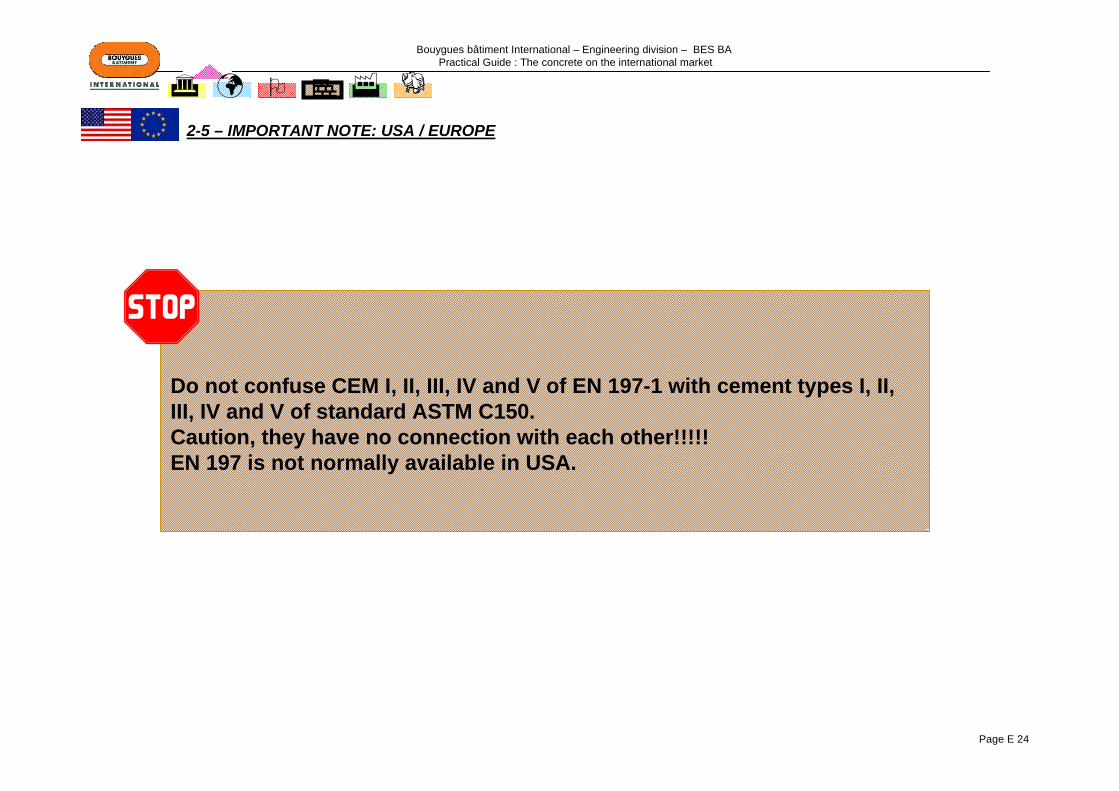
Bouygues bâtiment International – Engineering division – BES BA Practical Guide : The concrete on the international market
Page E 24
Do not confuse CEM I, II, III, IV and V of EN 197-1 with cement types I, II, III, IV and V of standard ASTM C150.Caution, they have no connection with each other!!!!!EN 197 is not normally available in USA.
2-5 – IMPORTANT NOTE: USA / EUROPE

Bouygues bâtiment International – Engineering division – BES BA Practical Guide : The concrete on the international market
Page E 25
Cements
GOST 30515: Cements - General specifications
GOST 10178: Portland cement and blast Portland cement - Standards
GOST 969: Alumina and high alumina cements - Specification
GOST 22266: Sulphate-resisting cements - Specifications
GOST 965: Portland cements, white - Specification
GOST 11052: Gypsum-alumina expanding cement
GOST 15825: Coloured Portland cement - Specifications
Additions GOST 24640: Additions for cements - Classification
2-6 – RUSSIA: MAIN NORMATIVE TEXTS RELATING TO CEMENTS
Bouygues bâtiment International – Engineering division – BES BA Practical Guide : The concrete on the international market
Page E 26
3 - ADDITIVES
3-1 – CONSISTENCE OF THE CONCRETE3-1-1 – Plasticisers / Water reducers………………………………..Page E 273-1-2 – Superplasticisers………………………………………..…….Page E 273-1-3 – Properties, mix proportions, application, ………………...Page E 28
3-2 – SETTING / HARDENING3-2-1 – Setting / hardening accelerator………………………..…...Page E 293-2-2 – Setting retarders ……………………………………………..Page E 293-2-3 – Properties, mix proportions, application ………………...Page E 30
3-3 – PROPERTIES OF THE CONCRETE 3-3-1 – Air entrainer ……………………………………………………Page E 313-3-2 – Integral waterproofing ……………………………………….Page E 313-3-3 – Properties, mix proportions, application ……………......Page E 32
3- 4 – CHOICE OF TYPE OF ADDITIVE DEPENDING ON ITS PROPERTIES.Page E 33
3-5 – MAIN NORMATIVE TEXTS RELATING TO ADDITIVES…..Page E 33

Bouygues bâtiment International – Engineering division – BES BA Practical Guide : The concrete on the international market
Page E 27
The main function of these additives, in addition to consistence, is to cause an increase in mechanical strength by
a reduction in the water content of the concrete.
Added to a concrete, generally just before it is placed, their main function is to cause a major improvement in the
consistence of the mix.
Fields of application:All standard concretes up to 30 MPaReady-mix concreteConcrete for lightweight prefabricationConcrete for civil engineering structuresConcrete for roadsConcrete for civil engineeringAgricultural concrete
Fields of application:Concrete for prefabricationReady-mix concreteDense and lightweight concreteConcrete for civil engineering structuresConcrete for industrial slabsConcrete for use in building Prestressed concrete Pumped concrete Concrete for deep foundationsConcrete for heavily-reinforced constructionsConcrete subjected to a corrosive environmentHigh-performance concrete, very high-performance Concrete, ultra-high-performance concrete Self-levelling, self-placing concreteArchitectonic concrete
3-1 – CONSISTENCE OF THE CONCRETE
3-1-1 – Plasticisers / Water reducers 3-1-2 – Superplasticisers
These additives modify the rheological behaviour of the concrete, mortar or grout in its fresh condition, before it starts to set. They lower the shear threshold and modify its
viscosity.
cement Dispersed state of the cement
water
lump
Better hydratation
Grain of cement
Addition of plasticiser
Hydrarted surface
cement waterDispersed state of
the cement
lump
Hydrarted surface
Grain of cement
Better hydratation
Addition of superplasticiser

Bouygues bâtiment International – Engineering division – BES BA Practical Guide : The concrete on the international market
Page E 28
Water-reducing plasticisers Superplasticisers
Quantity used as a % of the mass of the cement Generally < 0.5% Generally 0.5% to 3%
Addition to the mixing water In the concrete before placing
Effect on the placing of the concrete At constant consistence, water reduction >6.5%At constant water/cement ratio, large improvement
in concrete fluidity; improvement in slump of at least 80 mm
Strength at all stages •Greater than that of control•Minimum increase of 10%
In comparison with control, slight reduction possible
Favourable secondary effects
•Increase in compaction, reduction in permeability
•Possible improvement in resistance of the concrete to corrosive chemicals
The use of such additives may enable high-performance concrete to be created, with a low
water/cement ratio
Other effects Possible slight increase in shrinkage
with with plasticiserplasticiserSlumpSlump
(cm)(cm)
W:CW:C
controlcontrol
"Fluidifying" effect at same W:C"Fluidifying" effect at same W:C
10
15
5
0,3 0,4 0,5 0,6
W:C=0.50W:C=0.50
W:C=0.50W:C=0.5020
Slump 6Slump 6
Slump 19Slump 19
SlumpSlump(cm)(cm) with with
plasticiserplasticiser controlcontrol
"Water"Water--reducing" effect at same consistencereducing" effect at same consistence
10
15
5
0,3 0,4 0,5 0,6
W:CW:C
W:C=0.50W:C=0.50W:C=0.34W:C=0.34
20
SlumpSlump(cm)(cm) with with
plasticiserplasticiser controlcontrol
Double effectDouble effect
10
15
5
0,3 0,4 0,5 0,6
W:CW:C
W:C=0.50W:C=0.50W:C=0.34W:C=0.34
W:C=0.50W:C=0.5020
W:C=0.42W:C=0.42
3-1-3 – Properties, mix proportions, application
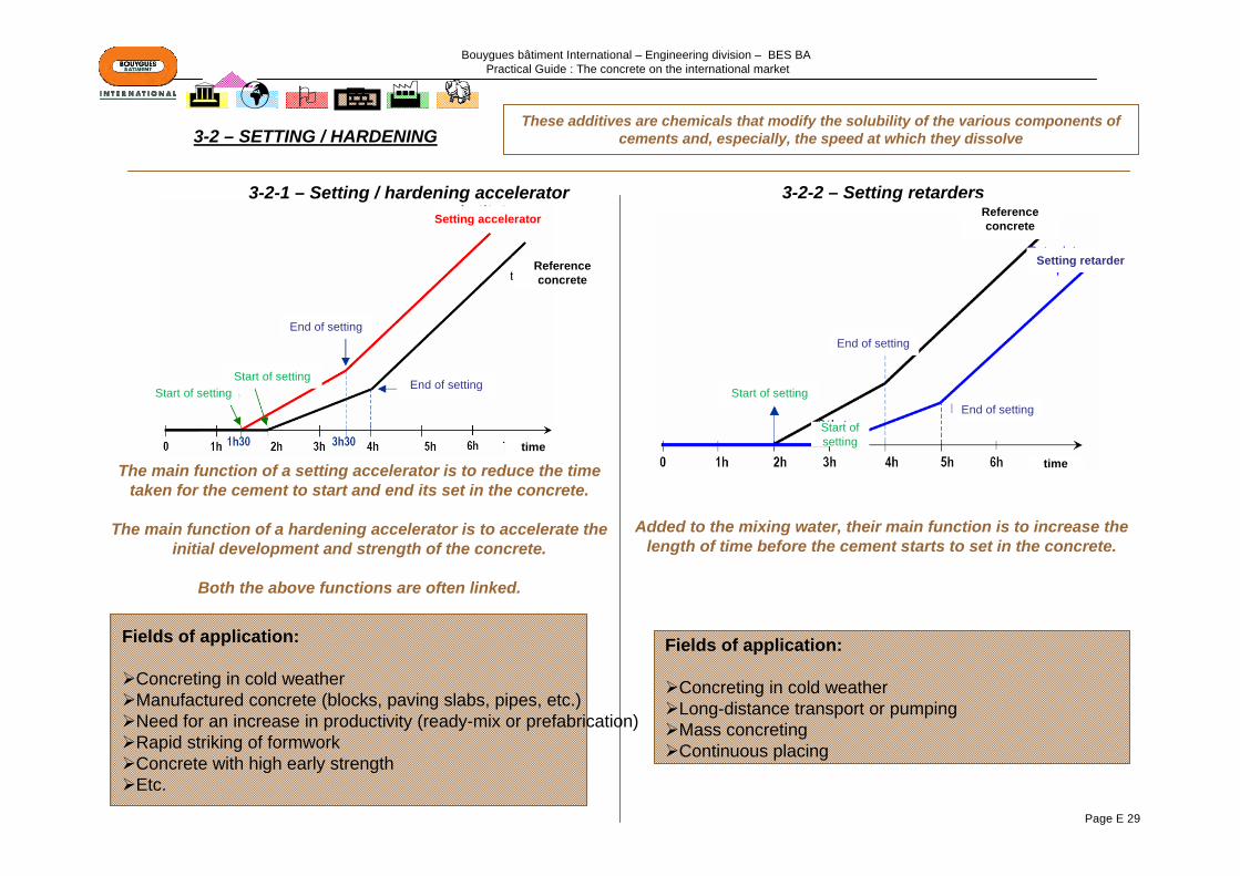
Bouygues bâtiment International – Engineering division – BES BA Practical Guide : The concrete on the international market
Page E 29
The main function of a setting accelerator is to reduce the timetaken for the cement to start and end its set in the concrete.
The main function of a hardening accelerator is to accelerate the initial development and strength of the concrete.
Both the above functions are often linked.
Added to the mixing water, their main function is to increase the length of time before the cement starts to set in the concrete.
Fields of application:
Concreting in cold weatherManufactured concrete (blocks, paving slabs, pipes, etc.)Need for an increase in productivity (ready-mix or prefabrication)Rapid striking of formworkConcrete with high early strengthEtc.
Fields of application:
Concreting in cold weatherLong-distance transport or pumpingMass concretingContinuous placing
3-2 – SETTING / HARDENING
3-2-1 – Setting / hardening accelerator 3-2-2 – Setting retarders
These additives are chemicals that modify the solubility of the various components of cements and, especially, the speed at which they dissolve
Setting accelerator
Reference concrete
End of settingStart of setting
Start of setting
End of setting
time
Reference concrete
End of setting
End of settingStart of setting
Start of setting
Setting retarder
time

Bouygues bâtiment International – Engineering division – BES BA Practical Guide : The concrete on the international market
Page E 30
Setting accelerators Hardening accelerators setting retarders
Quantity used/mass of cement 1 to 3% 0,2 to 3% 0.1 to 1%
Addition To the mixing water
Effect on setting Acceleration will vary, depending on mix proportion, types of cement and temperature
Very variable delays, depending on mix proportions, cement,
temperature
Effects on strength
Initial (before 3 days) Increased to 1 or 2 days Increased Reduced to 1 or 2 days
Final (before 28 days)
Slightly reduced (more so if setting has been
accelerated)
Unchanged or slightly reduced Slightly increased
Favourable secondary effects – – Improvement in consistence, with
possible water reduction
Other effects Possible slight increase in shrinkage –
3-2-3 – Properties, mix proportions, application
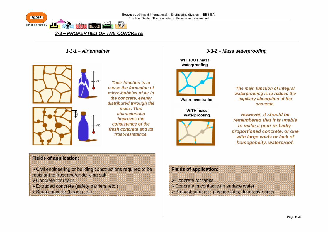
Bouygues bâtiment International – Engineering division – BES BA Practical Guide : The concrete on the international market
Page E 31
Their function is to cause the formation of micro-bubbles of air in
the concrete, evenly distributed through the
mass. This characteristic improves the
consistence of the fresh concrete and its
frost-resistance.
The main function of integral waterproofing is to reduce the
capillary absorption of the concrete.
However, it should be remembered that it is unable
to make a poor or badly-proportioned concrete, or one
with large voids or lack of homogeneity, waterproof.
Fields of application:
Civil engineering or building constructions required to be resistant to frost and/or de-icing salt
Concrete for roadsExtruded concrete (safety barriers, etc.)Spun concrete (beams, etc.)
Fields of application:
Concrete for tanksConcrete in contact with surface waterPrecast concrete: paving slabs, decorative units
3-3 – PROPERTIES OF THE CONCRETE
3-3-1 – Air entrainer 3-3-2 – Mass waterproofing
WITHOUT mass waterproofing
WITH mass waterproofing
Water penetration

Bouygues bâtiment International – Engineering division – BES BA Practical Guide : The concrete on the international market
Page E 32
Air-entrainers Waterproofing
Mix proportion (mass of cement) 0.01 to 0.5% 1 to 3%
Freeze/thaw cycle resistance
Use recommendedWorthwhile improvement –
Resistance to atmospheric corrosion, CO2, maritime
atmospheresEffect varies
Improvement in resistance thanks to a reduction in air
permeability
Resistance to corrosive chemicals (selenitic water,
sulphated water, etc.)Possible improvement
Improvement, thanks to a reduction in the
permeability of the concrete
Favourable secondary effects
Improvement in surface finish –
3-3-3 – Properties, mix proportions, application

Bouygues bâtiment International – Engineering division – BES BA Practical Guide : The concrete on the international market
Page E 33
Property Additives water-reducers plasticisers super
plasticisershardening
acceleratorssetting
acceleratorssetting
retarders air-entrainers integral
waterproofing
consistence + + +Setting time - +
Strengthin short term (3 days) + + + + - -
in long term (>28 days) + + = + -Entrained air +
Frost-resistance of the set concrete + +Compactness + + +
Surface condition + +Permeability under hydraulic pressure - -
Europe USA RussiaEN 934-2: additives for concrete
Various types of additives:PlasticisersSuperplasticisersWater retainerIntegral waterproofingAir entrainerSetting acceleratorHardening acceleratorSetting retarderPlasticisers and setting retardersSuperplasticisers and setting retarderPlasticisers and setting accelerators
ASTM C260: air entraining admixtures
GOST 24211-03: concrete additives. General technical requirements
ASTM C494: chemical admixtures for concrete
Classification of admixtures into 7 types:Type A: PlasticiserType B: Setting retarder Type C: Setting / hardening accelerator Type D: Plasticiser and setting retarderType E: Plasticiser and setting acceleratorType F: SuperplasticiserType G: Superplasticiser and setting retarder
3-4 – CHOICE OF TYPE OF ADDITIVE DEPENDING ON ITS PROPERTIES
3-5 – STANDARDS: MAIN NORMATIVE TEXTS RELATING TO ADDITIVES

Bouygues bâtiment International – Engineering division – BES BA Practical Guide : The concrete on the international market
Page E 34
Action of water
It can cause deformationShrinkage, expansion, creation of capillary
systemsIt can reduce mechanical performance
This occurs when there is too much waterIt can make the concrete frost-sensitive:
Expansion when turned to iceIt can encourage electro-chemical reactions
Carbonation, corrosion, alkali reactionIt can encourage mould and the development of
organic materialsIt can dissolve:
Gypsum, plaster, chloridesIt can transport:
Chlorides, sulphates, carbon dioxideIt can carry substances:
By gravity, by capillarity, as vapour
Consequences of excess water
An increase in the quantity of water used will have a direct effect on the levels of mechanical performance
Lowering of compressive/bending strengthLowering of compactionIncrease in porosityIncrease in permeability
And on the general quality of the concrete:Segregation Greater penetration of external agents Defects in surface finishSensitivity to evaporation, etc.
Water/cement ratioThe addition of 10 litres of water per m3 of concrete causes a loss of approximately 3 to 5 N/mm²(MPa) in the 28-day compressive strength.
4 – MIXING WATER
Mixing water is needed for the manufacture of concrete. The total mixing water is the sum of the water added to the mix and the moisture on the surface of the aggregatesThe quality of the water has an influence on the characteristics of the concrete when fresh and hardened.
The use of drinking water for mixing concrete is considered to be a safe
practice
Optimum quantity
W/C ratio
Addition of water
Bouygues bâtiment International – Engineering division – BES BA Practical Guide : The concrete on the international market
Page E 35
5 – CONCRETE5-1 – EN 206-1: CONCRETE – Part 1: Specification, performance, production and conformity
5-1-1 – Introduction……………………………………………………………...Page E 365-1-2 – Classification
5-1-2-1 – Exposure …………………………………………………………....Page E 375-1-2-2 – Consistence of fresh concrete…………………………………..Page E 405-1-2-3 – Compressive strength of hardened concrete ………………..Page E 405-1-2-4 – Chloride content ………………………………………………..…Page E 415-1-2-5 – Maximum size of aggregates…………………………………….Page E 415-1-2-6- Density ……………………………………………………………….Page E 41
5-1-3 – Definition of concretes for placing an order5-1-3-1 – BPS: Designed Concretes………………………………………..Page E 425-1-3-2 – BCP: Prescribed Concretes ………………………………….….Page E 425-1-3-3 – BCPN: Standardised Prescribed Concretes…..Page E 42
5-1-4 – Recommendations for the limits of concrete composition …....Page E 435-1-5 – French specifications .....…………………………………………......Page E 445-1-6 – British specifications .....…………………………………………......Page E 45
5-2 – SPECIFICATION OF FRESH CONCRETE IN USA…………………………….….Page E 48
5-3 – RUSSIA: MAIN NORMATIVE TEXTS RELATING TO CONCRETE ……………Page E 49

Bouygues bâtiment International – Engineering division – BES BA Practical Guide : The concrete on the international market
Page E 36
CONCRETES CONCERNED: ALL STRUCTURAL CONCRETESAll structural concretes, whether ready-mixed, mixed on site by the user of the concrete or mixes intended for the prefabrication of concrete products.The standard applies also to dense concretes and to certain lightweight concretes.
CONCRETES OUTSIDE THE FIELD OF APPLICATION: THOSE THAT ARE NOT STRUCTURAL• Concrete in trenches• Infill concrete• Packing concrete• Concrete blindings• Aerated concrete• Foam concrete• No-fines concrete• Refractory concrete• Concrete with non-mineral aggregate• Very lightweight concrete (Density <800 kg/m3)
Definition of concretes for placing an order:
Usual case BPS: Designed Concretes → BPS concretes are products that are mainly offered by ready-mixed
concrete companiesParticular case
(concrete formulated by the contractor)
BCP: Prescribed Concretes
→ BCP concretes must be formulated by a competent specifier and are products made mainly on site.
Rare case(concrete with a mix proportion
made by a tradesman)
BCPN: Standardised Prescribed Concretes
OBLIGATORY CHARACTERISTICS FOR DESIGNING A
CONCRETE
Exposure class
Strength class
Consistence class
Chloride class
Max. size of aggregates
Example of descriptionXC1 C25/30 S3 Cl 0.40 22.4
XC1
C25/30
S3
Cl 0.40
22.4
Exposure class
Compression strength class on a cylinder/cube
Consistence class of the fresh concrete
Chloride class
Maximum size of the aggregates
5-1 – EN 206-1: CONCRETE – Part 1: Specification, performance, production and conformity
5-1-1 – Introduction
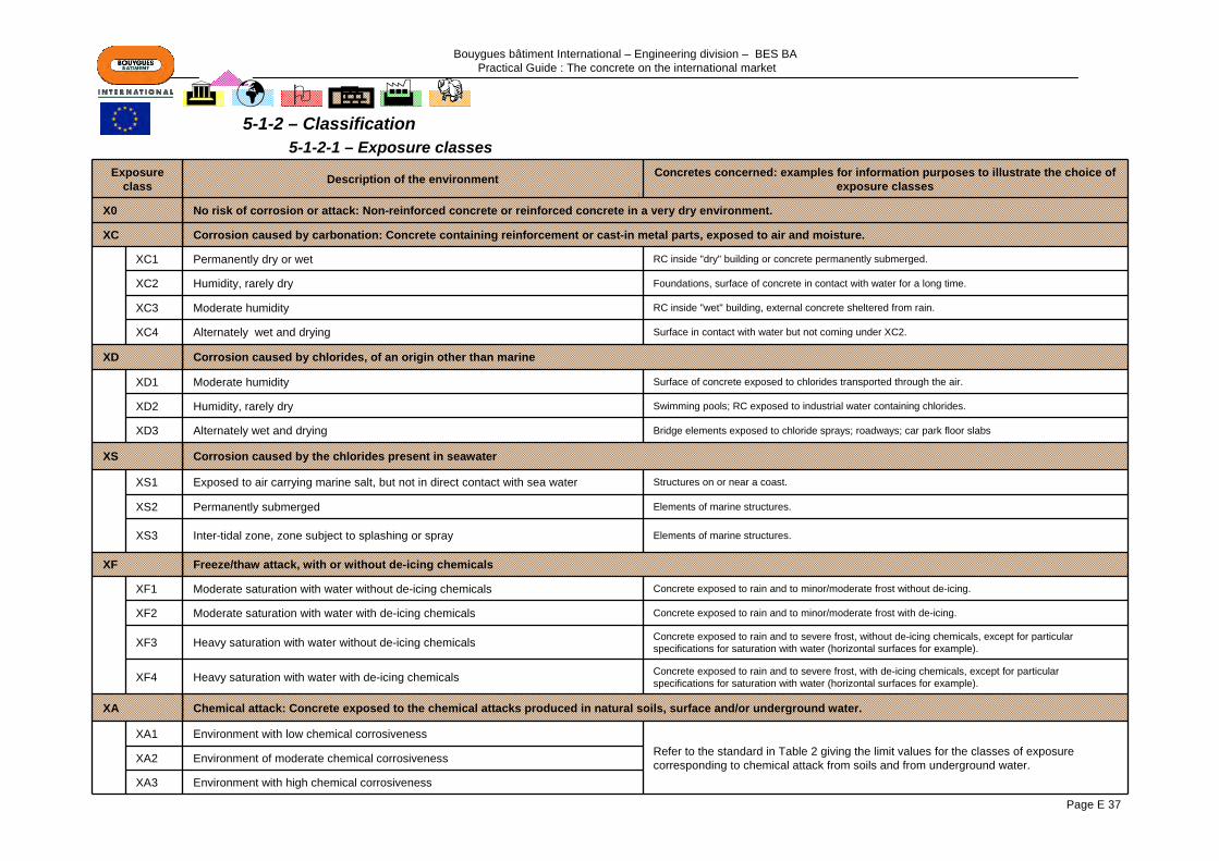
Bouygues bâtiment International – Engineering division – BES BA Practical Guide : The concrete on the international market
Page E 37
Exposure class Description of the environment Concretes concerned: examples for information purposes to illustrate the choice of
exposure classes
X0 No risk of corrosion or attack: Non-reinforced concrete or reinforced concrete in a very dry environment.
XC Corrosion caused by carbonation: Concrete containing reinforcement or cast-in metal parts, exposed to air and moisture.
XC1 Permanently dry or wet RC inside "dry" building or concrete permanently submerged.
XC2 Humidity, rarely dry Foundations, surface of concrete in contact with water for a long time.
XC3 Moderate humidity RC inside "wet" building, external concrete sheltered from rain.
XC4 Alternately wet and drying Surface in contact with water but not coming under XC2.
XD Corrosion caused by chlorides, of an origin other than marine
XD1 Moderate humidity Surface of concrete exposed to chlorides transported through the air.
XD2 Humidity, rarely dry Swimming pools; RC exposed to industrial water containing chlorides.
XD3 Alternately wet and drying Bridge elements exposed to chloride sprays; roadways; car park floor slabs
XS Corrosion caused by the chlorides present in seawater
XS1 Exposed to air carrying marine salt, but not in direct contact with sea water Structures on or near a coast.
XS2 Permanently submerged Elements of marine structures.
XS3 Inter-tidal zone, zone subject to splashing or spray Elements of marine structures.
XF Freeze/thaw attack, with or without de-icing chemicals
XF1 Moderate saturation with water without de-icing chemicals Concrete exposed to rain and to minor/moderate frost without de-icing.
XF2 Moderate saturation with water with de-icing chemicals Concrete exposed to rain and to minor/moderate frost with de-icing.
XF3 Heavy saturation with water without de-icing chemicals Concrete exposed to rain and to severe frost, without de-icing chemicals, except for particular specifications for saturation with water (horizontal surfaces for example).
XF4 Heavy saturation with water with de-icing chemicals Concrete exposed to rain and to severe frost, with de-icing chemicals, except for particular specifications for saturation with water (horizontal surfaces for example).
XA Chemical attack: Concrete exposed to the chemical attacks produced in natural soils, surface and/or underground water.
XA1 Environment with low chemical corrosivenessRefer to the standard in Table 2 giving the limit values for the classes of exposure corresponding to chemical attack from soils and from underground water.XA2 Environment of moderate chemical corrosiveness
XA3 Environment with high chemical corrosiveness
5-1-2-1 – Exposure classes 5-1-2 – Classification
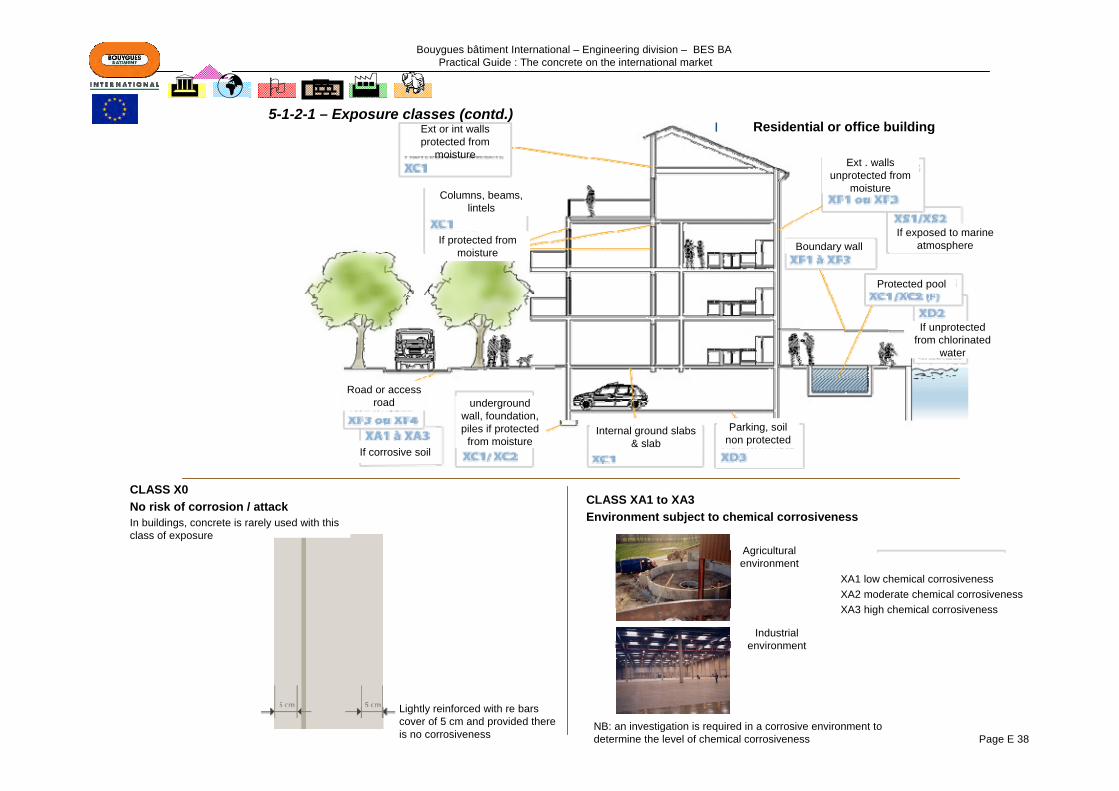
Bouygues bâtiment International – Engineering division – BES BA Practical Guide : The concrete on the international market
Page E 38
5-1-2-1 – Exposure classes (contd.)Residential or office buildingExt or int walls
protected from moisture
Parking, soil non protected
Internal ground slabs & slab
underground wall, foundation, piles if protected
from moistureIf corrosive soil
Road or access road
Boundary wallIf exposed to marine
atmosphere
Ext . walls unprotected from
moisture
Protected pool
If unprotected from chlorinated
water
Columns, beams, lintels
If protected from moisture
CLASS X0 No risk of corrosion / attackIn buildings, concrete is rarely used with this class of exposure
Lightly reinforced with re bars cover of 5 cm and provided there is no corrosiveness
CLASS XA1 to XA3 Environment subject to chemical corrosiveness
XA1 low chemical corrosivenessXA2 moderate chemical corrosivenessXA3 high chemical corrosiveness
Industrial environment
Agricultural environment
NB: an investigation is required in a corrosive environment to determine the level of chemical corrosiveness
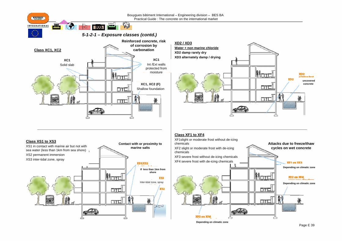
Bouygues bâtiment International – Engineering division – BES BA Practical Guide : The concrete on the international market
Page E 39
5-1-2-1 – Exposure classes (contd.)
Class XC1, XC2
XC1, XC2 (F)Shallow foundation
XC1Int /Ext walls
protected from moisture
Reinforced concrete, risk of corrosion by
carbonation
XC1Solid slab
XD2 / XD3Water + non marine chlorideXD2 damp rarely dryXD3 alternately damp / drying
uncovered concrete
Class XS1 to XS3XS1 in contact with marine air but not with sea water (less than 1km from sea shore)XS2 permanent immersionXS3 inter-tidal zone, spray
Inter-tidal zone, spray
If less than 1km from shore
Contact with or proximity to marine salts
Class XF1 to XF4XF1slight or moderate frost without de-icing chemicalsXF2 slight or moderate frost with de-icing chemicalsXF3 severe frost without de-icing chemicalsXF4 severe frost with de-icing chemicals
Attacks due to freeze/thaw cycles on wet concrete
Depending on climatic zone
Depending on climatic zone
Depending on climatic zone
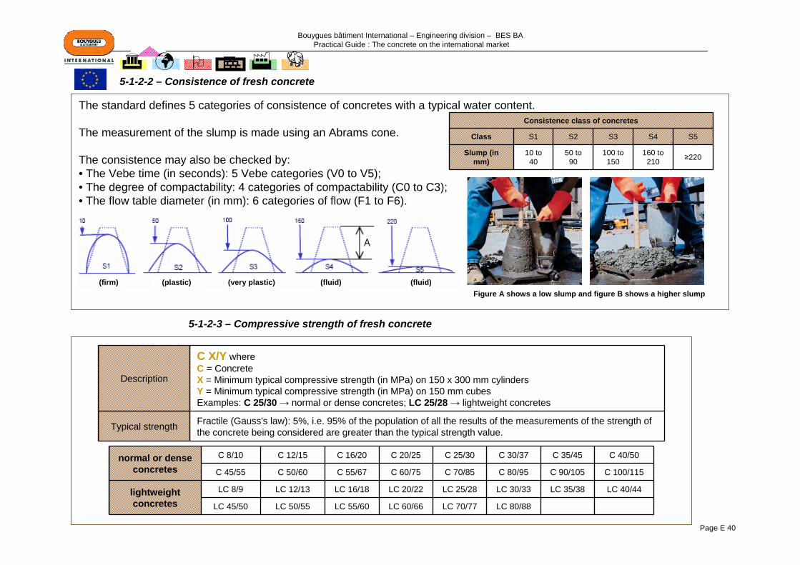
Bouygues bâtiment International – Engineering division – BES BA Practical Guide : The concrete on the international market
Page E 40
The standard defines 5 categories of consistence of concretes with a typical water content.
The measurement of the slump is made using an Abrams cone.
The consistence may also be checked by:• The Vebe time (in seconds): 5 Vebe categories (V0 to V5);• The degree of compactability: 4 categories of compactability (C0 to C3);• The flow table diameter (in mm): 6 categories of flow (F1 to F6).
Description
C X/Y whereC = ConcreteX = Minimum typical compressive strength (in MPa) on 150 x 300 mm cylindersY = Minimum typical compressive strength (in MPa) on 150 mm cubesExamples: C 25/30 → normal or dense concretes; LC 25/28 → lightweight concretes
Typical strength Fractile (Gauss's law): 5%, i.e. 95% of the population of all the results of the measurements of the strength of the concrete being considered are greater than the typical strength value.
Consistence class of concretes
Class S1 S2 S3 S4 S5
Slump (in mm)
10 to 40
50 to 90
100 to 150
160 to 210 ≥220
normal or dense concretes
C 8/10 C 12/15 C 16/20 C 20/25 C 25/30 C 30/37 C 35/45 C 40/50
C 45/55 C 50/60 C 55/67 C 60/75 C 70/85 C 80/95 C 90/105 C 100/115
lightweight concretes
LC 8/9 LC 12/13 LC 16/18 LC 20/22 LC 25/28 LC 30/33 LC 35/38 LC 40/44
LC 45/50 LC 50/55 LC 55/60 LC 60/66 LC 70/77 LC 80/88
5-1-2-2 – Consistence of fresh concrete
5-1-2-3 – Compressive strength of fresh concrete
Figure A shows a low slump and figure B shows a higher slump(firm) (plastic) (very plastic) (fluid) (fluid)

Bouygues bâtiment International – Engineering division – BES BA Practical Guide : The concrete on the international market
Page E 41
Density (in kg/m3)
Lightweight concrete from 800 to 2000
Concrete of normal density from 2000 to 2600
Dense concrete ≥ 2600
Lightweight concretes are classified in six ranges of density.
The categories of chlorides enable the composition of the concrete to be adapted according to the risk of corrosion of the reinforcement.
Standard EN 206-1 defines the maximum content of chloride ions in the concrete not to be exceeded, according to its type of use.
Use of the concrete Chloride class
Maximum content (in
Cl-)
Concrete not containing steel reinforcement or cast-in metal parts Cl 1.0 1,00%
Concrete containing steel reinforcement or cast-in metal parts
Cl 0.20 0,20%
Cl 0.40 0,40%
Concrete containing steel pre-stressing reinforcement
Cl 0.10 0,10%
Cl 0.20 0,20%
The classification of the concrete depends on the maximum size of the aggregate: nominal size greater than the largest aggregate used in the concrete (Dmax).
5-1-2-4 – Chloride content
5-1-2-5 – Maximum size of aggregates
5-1-2-6 – Density
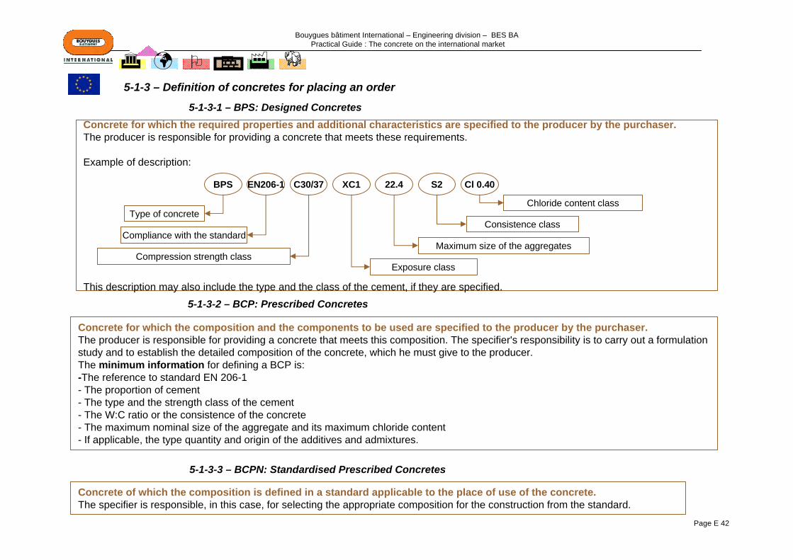
Bouygues bâtiment International – Engineering division – BES BA Practical Guide : The concrete on the international market
Page E 42
Concrete for which the required properties and additional characteristics are specified to the producer by the purchaser.The producer is responsible for providing a concrete that meets these requirements.
Example of description:
This description may also include the type and the class of the cement, if they are specified.
Concrete for which the composition and the components to be used are specified to the producer by the purchaser. The producer is responsible for providing a concrete that meets this composition. The specifier's responsibility is to carry out a formulation study and to establish the detailed composition of the concrete, which he must give to the producer.The minimum information for defining a BCP is:-The reference to standard EN 206-1- The proportion of cement- The type and the strength class of the cement- The W:C ratio or the consistence of the concrete- The maximum nominal size of the aggregate and its maximum chloride content- If applicable, the type quantity and origin of the additives and admixtures.
Concrete of which the composition is defined in a standard applicable to the place of use of the concrete. The specifier is responsible, in this case, for selecting the appropriate composition for the construction from the standard.
XC1C30/37 S2 Cl 0.4022.4BPS EN206-1
Type of concrete
Compliance with the standard
Compression strength classExposure class
Maximum size of the aggregates
Consistence class
Chloride content class
5-1-3-1 – BPS: Designed Concretes
5-1-3 – Definition of concretes for placing an order
5-1-3-2 – BCP: Prescribed Concretes
5-1-3-3 – BCPN: Standardised Prescribed Concretes
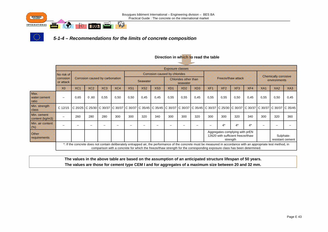
Bouygues bâtiment International – Engineering division – BES BA Practical Guide : The concrete on the international market
Page E 43
Exposure classes
No risk of corrosion or attack
Corrosion caused by carbonationCorrosion caused by chlorides
Freeze/thaw attack Chemically corrosive environmentsSeawater Chlorides other than
seawater
X0 XC1 XC2 XC3 XC4 XS1 XS2 XS3 XD1 XD2 XD3 XF1 XF2 XF3 XF4 XA1 XA2 XA3
Max. water:cement ratio
– 0,65 0 ,60 0,55 0,50 0,50 0,45 0,45 0,55 0,55 0,45 0,55 0,55 0,50 0,45 0,55 0,50 0,45
Min. strength class C 12/15 C 20/25 C 25/30 C 30/37 C 30/37 C 30/37 C 35/45 C 35/45 C 30/37 C 30/37 C 35/45 C 30/37 C 25/30 C 30/37 C 30/37 C 30/37 C 30/37 C 35/45
Min. cement content (kg/m3) – 260 280 280 300 300 320 340 300 300 320 300 300 320 340 300 320 360
Min. air content (%) – – – – – – – – – – – – 4* 4* 4* – – –
Other requirements
Aggregates complying with prEN 12620 with sufficient freeze/thaw
strengthSulphate-
resistant cement*: If the concrete does not contain deliberately entrapped air, the performance of the concrete must be measured in accordance with an appropriate test method, in
comparison with a concrete for which the freeze/thaw strength for the corresponding exposure class has been determined.
Direction in which to read the table
5-1-4 – Recommendations for the limits of concrete composition
The values in the above table are based on the assumption of an anticipated structure lifespan of 50 years.The values are those for cement type CEM I and for aggregates of a maximum size between 20 and 32 mm.

Bouygues bâtiment International – Engineering division – BES BA Practical Guide : The concrete on the international market
Page E 44
The following table gives the limit values, applicable in France, of the composition and of the properties of concretes
Direction in which to read the table
Allowance for admixtures as a substitution for
cement is only permitted, within the limits of the
ratio A:A+C, with CEM I cements of class 42.5 or
52.5.
No risk of corrosion or
attack
Corrosion caused by carbonation
Corrosion caused by chloridesFreeze/thaw attack
(refer to the map giving zones of frost in the standard)
Chemically corrosive environments
Seawater Chlorides other than seawater
X0 XC1 XC2 XC3 XC4 XS1 XS2 XS3 XD1 XD2 XD3 XF1 XF2 XF3 XF4 XA1 XA2 XA3
Ratio Eeff/binder eq* max – 0,65
Num
erical values identical to XC
1
Num
erical values identical to XF1
Num
erical values identical to XF1
Num
erical values identical to XS
2
0,55 0,50
Num
erical values identical to XF1
0,55 0,50 0,60 0,55 0,55 0,45 0,55 0,50 0,45
Minimum strength class – C20/25 C30/37 C35/45 C30/37 C35/45 C25/30 C25/30 C30/37 C30/37 C30/37 C35/45 C40/50
Min. binder eq. content (kg/m3) when
Dmax= 20 mm150 260* 330 350 330 350 280* 300 315 340 330 350 385
Min. air content (%) – – – – – – – 4** 4** 4** – – –
Max. ratio
A:(A
+C)
Fly ash 0,30 0,30 0,15 0,15 0,15 0,15 0,30 0,30 0,30 0,15* 0,30* 0,30* 0,00Silica fume 0,10 0,10 0,10 0,10 0,10 0,10 0,10 0,10 0,10 0,10 0,10 0,10 0,10
Ground slag 0,30 0,30 0,15 0,15 0,15 0,15 0,30 0,30 0,30 0,15 0,30* 0,30* 0,00Limestone addition 0,25 0,25 0,05 0,05 0,05 0,05 0,25 0,25 0,25 0,05 0,00 0,00 0,00
Silica addition 0,20 0,20 0,15 0,15 0,15 0,15 0,20 0,20 0,20 0,15 0,00 0,00 0,00
Nature of the cement – – PM* PM* – – – – – ** ** ** **
•*Eeff= Effective water = total water – water absorbed by the aggregatesBinder eq = binder equivalent = Cement + k Additions (k depends on the type of cement and of the addition)•**refer to the annotations in FR EN 206-1 Table NA.F.1
frost-proof aggregateCheck that the
concrete is suitable for the expected levels of
performance
5-1-5 – French specifications
Bouygues bâtiment International – Engineering division – BES BA Practical Guide : The concrete on the international market
Page E 45
In the United Kingdom, standard BS EN 206-1 is supplemented by BS 8500: Complementary British Standard to BS EN 206-1.
In this supplement, there is an additional way to define a concrete in an order:designed concrete (symbolised by RC, PAV, FND, GEN) for which the composition and the requirements are defined precisely in BS 8500 and which only applies to a concrete not exposed to exposure classes XS, XC and/or XA.
5-1-6 – British specifications
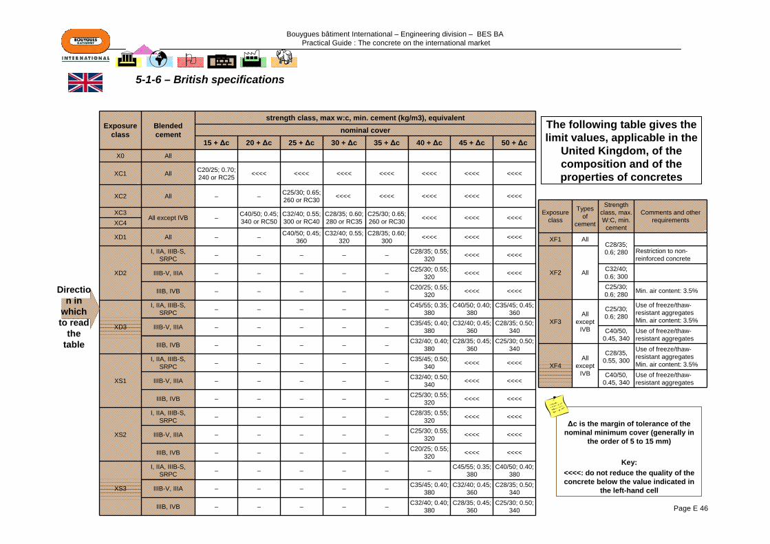
Bouygues bâtiment International – Engineering division – BES BA Practical Guide : The concrete on the international market
Page E 46
Exposure class
Blended cement
strength class, max w:c, min. cement (kg/m3), equivalent nominal cover
15 + Δc 20 + Δc 25 + Δc 30 + Δc 35 + Δc 40 + Δc 45 + Δc 50 + Δc
X0 All
XC1 All C20/25; 0.70; 240 or RC25 <<<< <<<< <<<< <<<< <<<< <<<< <<<<
XC2 All – – C25/30; 0.65; 260 or RC30 <<<< <<<< <<<< <<<< <<<<
XC3All except IVB – C40/50; 0.45;
340 or RC50C32/40; 0.55; 300 or RC40
C28/35; 0.60; 280 or RC35
C25/30; 0.65; 260 or RC30 <<<< <<<< <<<<
XC4
XD1 All – – C40/50; 0.45; 360
C32/40; 0.55; 320
C28/35; 0.60; 300 <<<< <<<< <<<<
XD2
I, IIA, IIIB-S, SRPC – – – – – C28/35; 0.55;
320 <<<< <<<<
IIIB-V, IIIA – – – – – C25/30; 0.55; 320 <<<< <<<<
IIIB, IVB – – – – – C20/25; 0.55; 320 <<<< <<<<
XD3
I, IIA, IIIB-S, SRPC – – – – – C45/55; 0.35;
380C40/50; 0.40;
380C35/45; 0.45;
360
IIIB-V, IIIA – – – – – C35/45; 0.40; 380
C32/40; 0.45; 360
C28/35; 0.50; 340
IIIB, IVB – – – – – C32/40; 0.40; 380
C28/35; 0.45; 360
C25/30; 0.50; 340
XS1
I, IIA, IIIB-S, SRPC – – – – – C35/45; 0.50;
340 <<<< <<<<
IIIB-V, IIIA – – – – – C32/40; 0.50; 340 <<<< <<<<
IIIB, IVB – – – – – C25/30; 0.55; 320 <<<< <<<<
XS2
I, IIA, IIIB-S, SRPC – – – – – C28/35; 0.55;
320 <<<< <<<<
IIIB-V, IIIA – – – – – C25/30; 0.55; 320 <<<< <<<<
IIIB, IVB – – – – – C20/25; 0.55; 320 <<<< <<<<
XS3
I, IIA, IIIB-S, SRPC – – – – – – C45/55; 0.35;
380C40/50; 0.40;
380
IIIB-V, IIIA – – – – – C35/45; 0.40; 380
C32/40; 0.45; 360
C28/35; 0.50; 340
IIIB, IVB – – – – – C32/40; 0.40; 380
C28/35; 0.45; 360
C25/30; 0.50; 340
Exposure class
Types of
cement
Strength class, max. W:C, min.
cement
Comments and other requirements
XF1 AllC28/35; 0.6; 280
XF2 All
Restriction to non-reinforced concrete
C32/40; 0.6; 300C25/30; 0.6; 280 Min. air content: 3.5%
XF3All
except IVB
C25/30; 0.6; 280
Use of freeze/thaw-resistant aggregatesMin. air content: 3.5%
C40/50, 0.45, 340
Use of freeze/thaw-resistant aggregates
XF4All
except IVB
C28/35, 0.55, 300
Use of freeze/thaw-resistant aggregatesMin. air content: 3.5%
C40/50, 0.45, 340
Use of freeze/thaw-resistant aggregates
Direction in
which to read
the table
The following table gives the limit values, applicable in the
United Kingdom, of the composition and of the properties of concretes
Δc is the margin of tolerance of the nominal minimum cover (generally in
the order of 5 to 15 mm)
Key:<<<<: do not reduce the quality of the concrete below the value indicated in
the left-hand cell
5-1-6 – British specifications
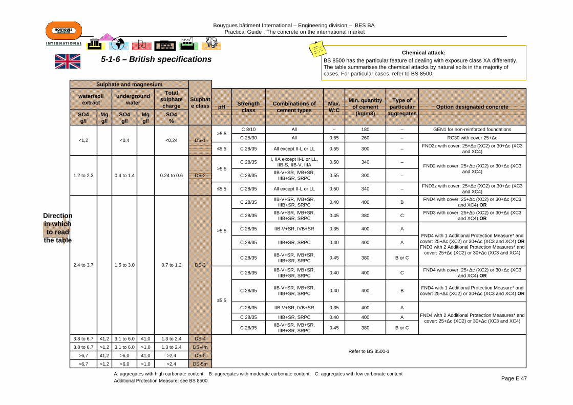
Bouygues bâtiment International – Engineering division – BES BA Practical Guide : The concrete on the international market
Page E 47
Sulphate and magnesium
Sulphate class
water/soil extract
underground water
Total sulphate charge pH Strength
classCombinations of
cement typesMax. W:C
Min. quantity of cement
(kg/m3)
Type of particular
aggregatesOption designated concrete
SO4g/l
Mgg/l
SO4g/l
Mgg/l
SO4%
<1,2 <0,4 <0,24 DS-1>5.5
C 8/10 All – 180 – GEN1 for non-reinforced foundations
C 25/30 All 0.65 260 – RC30 with cover 25+Δc
≤5.5 C 28/35 All except II-L or LL 0.55 300 – FND2z with cover: 25+Δc (XC2) or 30+Δc (XC3 and XC4)
1.2 to 2.3 0.4 to 1.4 0.24 to 0.6 DS-2>5.5
C 28/35 I, IIA except II-L or LL, IIB-S, IIB-V, IIIA 0.50 340 –
FND2 with cover: 25+Δc (XC2) or 30+Δc (XC3 and XC4)
C 28/35 IIB-V+SR, IVB+SR, IIIB+SR, SRPC 0.55 300 –
≤5.5 C 28/35 All except II-L or LL 0.50 340 – FND3z with cover: 25+Δc (XC2) or 30+Δc (XC3 and XC4)
2.4 to 3.7 1.5 to 3.0 0.7 to 1.2 DS-3
>5.5
C 28/35 IIB-V+SR, IVB+SR, IIIB+SR, SRPC 0.40 400 B FND4 with cover: 25+Δc (XC2) or 30+Δc (XC3
and XC4) OR
C 28/35 IIB-V+SR, IVB+SR, IIIB+SR, SRPC 0.45 380 C FND3 with cover: 25+Δc (XC2) or 30+Δc (XC3
and XC4) OR
C 28/35 IIB-V+SR, IVB+SR 0.35 400 AFND4 with 1 Additional Protection Measure* and cover: 25+Δc (XC2) or 30+Δc (XC3 and XC4) ORFND3 with 2 Additional Protection Measures* and
cover: 25+Δc (XC2) or 30+Δc (XC3 and XC4)
C 28/35 IIIB+SR, SRPC 0.40 400 A
C 28/35 IIB-V+SR, IVB+SR, IIIB+SR, SRPC 0.45 380 B or C
≤5.5
C 28/35 IIB-V+SR, IVB+SR, IIIB+SR, SRPC 0.40 400 C FND4 with cover: 25+Δc (XC2) or 30+Δc (XC3
and XC4) OR
C 28/35 IIB-V+SR, IVB+SR, IIIB+SR, SRPC 0.40 400 B FND4 with 1 Additional Protection Measure* and
cover: 25+Δc (XC2) or 30+Δc (XC3 and XC4) OR
C 28/35 IIB-V+SR, IVB+SR 0.35 400 AFND4 with 2 Additional Protection Measures* and
cover: 25+Δc (XC2) or 30+Δc (XC3 and XC4)C 28/35 IIIB+SR, SRPC 0.40 400 A
C 28/35 IIB-V+SR, IVB+SR, IIIB+SR, SRPC 0.45 380 B or C
3.8 to 6.7 ≤1,2 3.1 to 6.0 ≤1,0 1.3 to 2.4 DS-4
Refer to BS 8500-13.8 to 6.7 >1,2 3.1 to 6.0 >1,0 1.3 to 2.4 DS-4m
>6,7 ≤1,2 >6,0 ≤1,0 >2,4 DS-5
>6,7 >1,2 >6,0 >1,0 >2,4 DS-5m
A: aggregates with high carbonate content; B: aggregates with moderate carbonate content; C: aggregates with low carbonate contentAdditional Protection Measure: see BS 8500
Direction in which to read
the table
Chemical attack:BS 8500 has the particular feature of dealing with exposure class XA differently. The table summarises the chemical attacks by natural soils in the majority of cases. For particular cases, refer to BS 8500.
5-1-6 – British specifications
Bouygues bâtiment International – Engineering division – BES BA Practical Guide : The concrete on the international market
Page E 48
5-2 – SPECIFICATION OF FRESH CONCRETE IN USA
Standard ASTM C94 (Standard specification for Ready Mixed Concrete) describes 3 ways of ordering and specifying concrete:
Option (1) Normal: When the client requires the supplier of the concrete to be responsible for the concrete mix. The Owner shall specify the types of materials to be used, the exposure to which the concrete will be subjected, the compressive strength required for structural purposes, the maximum size of the coarse aggregate, the air content, the admixtures and any other desired property, such as slump and minimum bending strength. The supplier shall certify that the factory, the plant and the materials used meet the requirements of the standard, that the mix proportion will produce a concrete of the quality and quantity specified and that the strengths, when they are evaluated, meet the requirements of the standard.
Option (2) Prescription: When the client is responsible for the mix proportions and for the properties of the concrete.The client shall specify, per cubic metre of concrete, the types and the quantities of materials to be used, the maximum nominal size of the aggregate, the proportions by weight of the coarse and of the fine aggregates, and the maximum mass of water. In addition, the client shall specify the air content, the type of admixture and the slump at the point of delivery. The supplier shall certify that the factory, the plant and all the materials used comply with the requirements of the standard.
Option (3) Performance: When the client requires the supplier of the concrete to be responsible for the concrete "as delivered".The client shall specify the class of concrete that will meet the conditions of exposure and the architectural, structural and durability criteria. The supplier shall certify that his quality control guarantees the performance criteria (measured and noted) and that the concrete will meet the specified performance criteria prior to delivery.

Bouygues bâtiment International – Engineering division – BES BA Practical Guide : The concrete on the international market
Page E 49
GOST 7473: Ready-mixed concrete - Specifications
GOST 25192: Concrete. Classification and technical requirements
GOST 25246: Concrete. Chemical resistant. Specifications
GOST 25820: Lightweight aggregates concrete. Specifications
GOST 26633: Heavyweight and sand concrete. Specifications
GOST 27006: Concrete. Rules for mix proportions
GOST 25246: Concrete Chemical resistant Specifications
GOST 25881: Chemical resistant concrete. Methods of test
5-3 – RUSSIA: MAIN NORMATIVE TEXTS RELATING TO CONCRETE
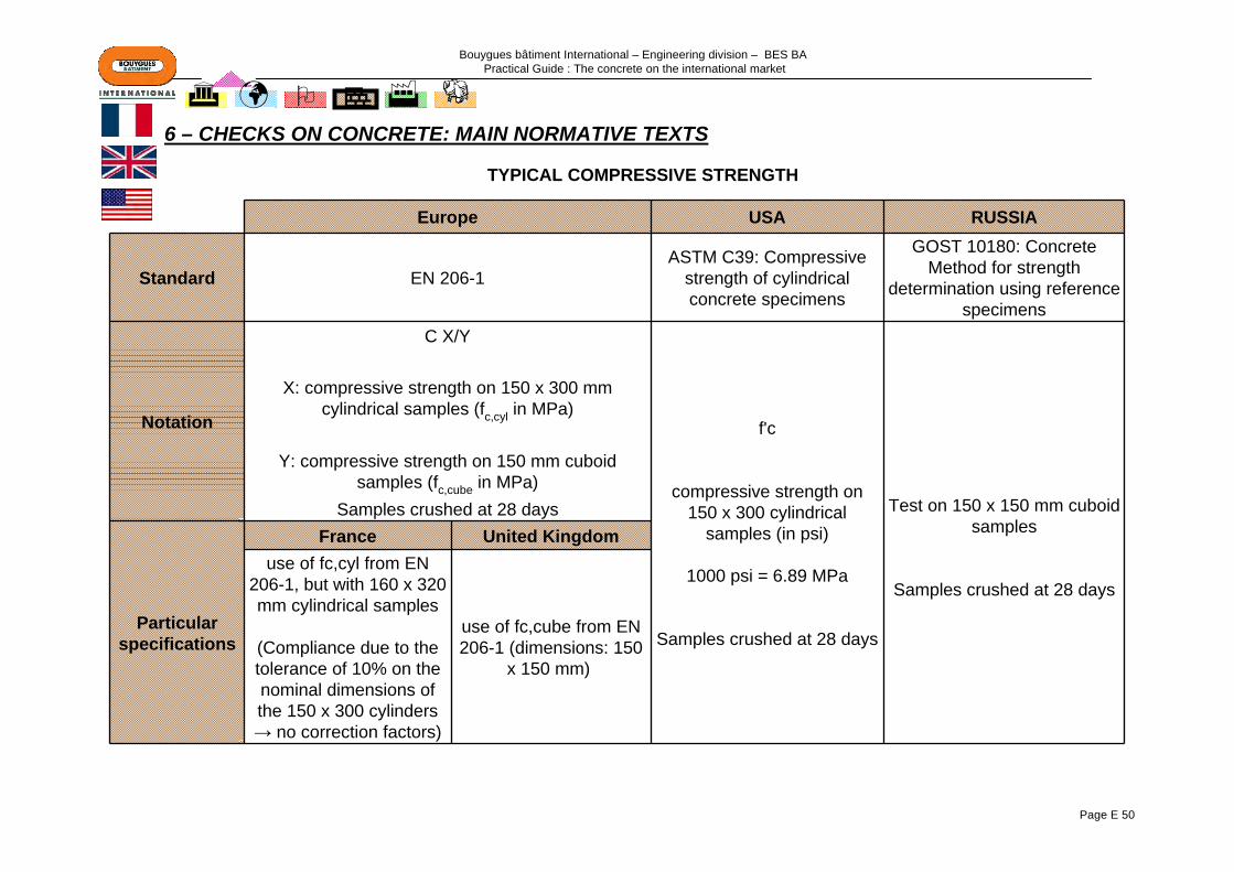
Bouygues bâtiment International – Engineering division – BES BA Practical Guide : The concrete on the international market
Page E 50
6 – CHECKS ON CONCRETE: MAIN NORMATIVE TEXTS
Europe USA RUSSIA
Standard EN 206-1ASTM C39: Compressive
strength of cylindrical concrete specimens
GOST 10180: Concrete Method for strength
determination using reference specimens
Notation
C X/Y
f'c
compressive strength on 150 x 300 cylindrical
samples (in psi)
1000 psi = 6.89 MPa
Samples crushed at 28 days
X: compressive strength on 150 x 300 mm cylindrical samples (fc,cyl in MPa)
Test on 150 x 150 mm cuboid samples
Samples crushed at 28 days
Y: compressive strength on 150 mm cuboid samples (fc,cube in MPa)
Samples crushed at 28 days
Particularspecifications
France United Kingdomuse of fc,cyl from EN
206-1, but with 160 x 320 mm cylindrical samples
(Compliance due to the tolerance of 10% on the nominal dimensions of the 150 x 300 cylinders → no correction factors)
use of fc,cube from EN 206-1 (dimensions: 150
x 150 mm)
TYPICAL COMPRESSIVE STRENGTH

Bouygues bâtiment International – Engineering division – BES BA Practical Guide : The concrete on the international market
Page E 51
Main normative texts on tests of fresh concreteFrance Great Britain
NF EN 12350: Test on fresh concrete
Part 1: SamplingPart 2: Slump testPart 3: Vebe testPart 4: Degree of compactabilityPart 5: Flow table testPart 6: Determination of the density of fresh concrete Part 7: Determination of the air content - Pressure methods
BS EN 12350: Testing fresh concrete
BS 1881-125: Testing concrete - Part 125: Method for mixing and sampling fresh concrete in the laboratory
BS 1881-128: Testing concrete - Part 128: Method for analysis of fresh concrete
BS 1881-129: Testing concrete - Part 129: Method for determination of density of partially compacted semi-dry fresh concrete
Main normative texts on tests of hardened concreteFrance Great Britain
NF EN 12390: Testing hardened concrete
Part 1: Shape, dimensions and other requirements for specimens and moulds Part 2: Making and curing specimens for strength tests Part 3: Compressive strength of test specimens Part 4: Compressive strength - Specification for testing machines Part 5: Flexural strength of test specimens Part 6: Tensile splitting strength of test specimens Part 7: Density of hardened concrete Part 8: Depth of penetration of water under pressure
BS EN 12390: Testing hardened concreteBS 1881-112: Testing concrete - Part 112: Methods of accelerated curing of test cubesBS 1881-113: Testing concrete - Part 113: Methods for making and curing no-fines test
cubes
BS 1881-119: Testing concrete - Part 119: Method for determination of compressive strength using portions of beams broken in flexure
BS 1881-121: Testing concrete - Part 121: Method for determination of static modulus of elasticity in compression
BS 1881-122: Testing concrete - Part 122: Method for determination of water absorption
BS 1881-124: Testing concrete - Part 124: Method for analysis of hardened concrete
BS 1881-127: Testing concrete - Part 127: Method for verifying the performance of a concrete cube compression machine using the comparative cube test
BS 1881-130: Testing concrete - Part 130: Method for temperature matched curing of concrete specimens
BS 1881-131: Testing concrete - Part 131: Method for testing cement in a reference concrete
6 – CHECKS ON CONCRETE: MAIN NORMATIVE TEXTS (Contd.)
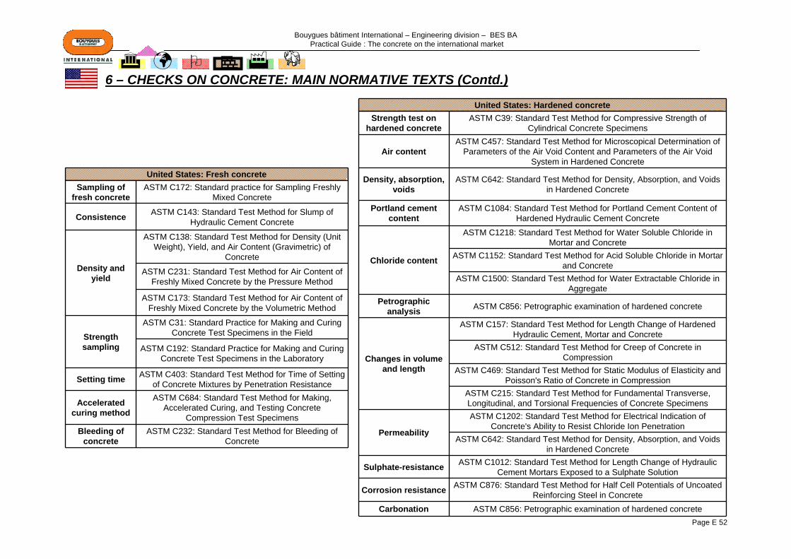
Bouygues bâtiment International – Engineering division – BES BA Practical Guide : The concrete on the international market
Page E 52
United States: Fresh concreteSampling of
fresh concreteASTM C172: Standard practice for Sampling Freshly
Mixed Concrete
Consistence ASTM C143: Standard Test Method for Slump of Hydraulic Cement Concrete
Density and yield
ASTM C138: Standard Test Method for Density (Unit Weight), Yield, and Air Content (Gravimetric) of
Concrete
ASTM C231: Standard Test Method for Air Content of Freshly Mixed Concrete by the Pressure Method
ASTM C173: Standard Test Method for Air Content of Freshly Mixed Concrete by the Volumetric Method
Strength sampling
ASTM C31: Standard Practice for Making and Curing Concrete Test Specimens in the Field
ASTM C192: Standard Practice for Making and Curing Concrete Test Specimens in the Laboratory
Setting time ASTM C403: Standard Test Method for Time of Setting of Concrete Mixtures by Penetration Resistance
Accelerated curing method
ASTM C684: Standard Test Method for Making, Accelerated Curing, and Testing Concrete
Compression Test SpecimensBleeding of
concreteASTM C232: Standard Test Method for Bleeding of
Concrete
United States: Hardened concreteStrength test on
hardened concreteASTM C39: Standard Test Method for Compressive Strength of
Cylindrical Concrete Specimens
Air contentASTM C457: Standard Test Method for Microscopical Determination of
Parameters of the Air Void Content and Parameters of the Air Void System in Hardened Concrete
Density, absorption, voids
ASTM C642: Standard Test Method for Density, Absorption, and Voids in Hardened Concrete
Portland cement content
ASTM C1084: Standard Test Method for Portland Cement Content of Hardened Hydraulic Cement Concrete
Chloride content
ASTM C1218: Standard Test Method for Water Soluble Chloride in Mortar and Concrete
ASTM C1152: Standard Test Method for Acid Soluble Chloride in Mortar and Concrete
ASTM C1500: Standard Test Method for Water Extractable Chloride in Aggregate
Petrographic analysis ASTM C856: Petrographic examination of hardened concrete
Changes in volume and length
ASTM C157: Standard Test Method for Length Change of Hardened Hydraulic Cement, Mortar and Concrete
ASTM C512: Standard Test Method for Creep of Concrete in Compression
ASTM C469: Standard Test Method for Static Modulus of Elasticity and Poisson's Ratio of Concrete in Compression
ASTM C215: Standard Test Method for Fundamental Transverse, Longitudinal, and Torsional Frequencies of Concrete Specimens
Permeability
ASTM C1202: Standard Test Method for Electrical Indication of Concrete's Ability to Resist Chloride Ion Penetration
ASTM C642: Standard Test Method for Density, Absorption, and Voids in Hardened Concrete
Sulphate-resistance ASTM C1012: Standard Test Method for Length Change of Hydraulic Cement Mortars Exposed to a Sulphate Solution
Corrosion resistance ASTM C876: Standard Test Method for Half Cell Potentials of Uncoated Reinforcing Steel in Concrete
Carbonation ASTM C856: Petrographic examination of hardened concrete
6 – CHECKS ON CONCRETE: MAIN NORMATIVE TEXTS (Contd.)
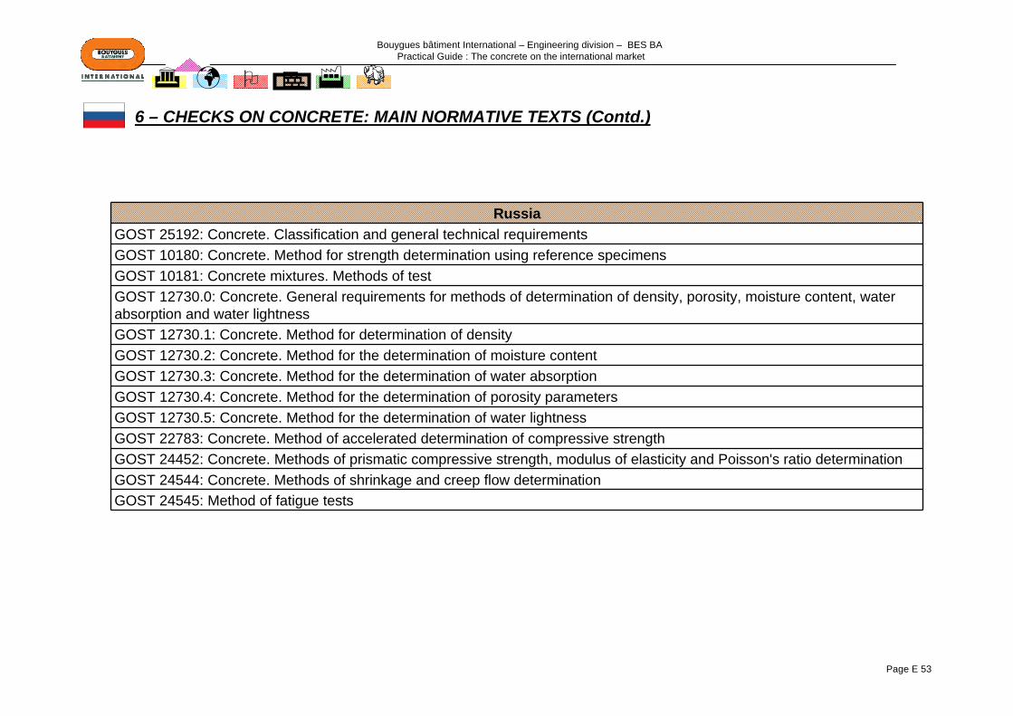
Bouygues bâtiment International – Engineering division – BES BA Practical Guide : The concrete on the international market
Page E 53
RussiaGOST 25192: Concrete. Classification and general technical requirementsGOST 10180: Concrete. Method for strength determination using reference specimensGOST 10181: Concrete mixtures. Methods of testGOST 12730.0: Concrete. General requirements for methods of determination of density, porosity, moisture content, water absorption and water lightnessGOST 12730.1: Concrete. Method for determination of densityGOST 12730.2: Concrete. Method for the determination of moisture contentGOST 12730.3: Concrete. Method for the determination of water absorptionGOST 12730.4: Concrete. Method for the determination of porosity parametersGOST 12730.5: Concrete. Method for the determination of water lightnessGOST 22783: Concrete. Method of accelerated determination of compressive strengthGOST 24452: Concrete. Methods of prismatic compressive strength, modulus of elasticity and Poisson's ratio determinationGOST 24544: Concrete. Methods of shrinkage and creep flow determinationGOST 24545: Method of fatigue tests
6 – CHECKS ON CONCRETE: MAIN NORMATIVE TEXTS (Contd.)
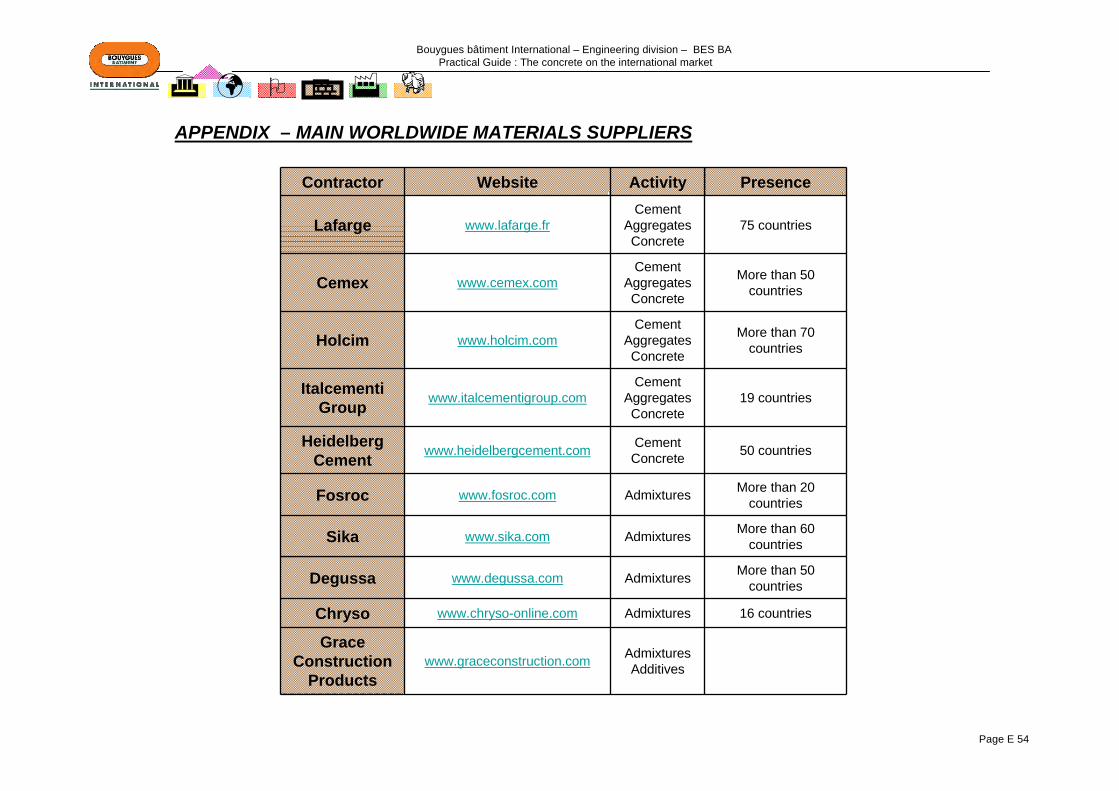
Bouygues bâtiment International – Engineering division – BES BA Practical Guide : The concrete on the international market
Page E 54
Contractor Website Activity Presence
Lafarge www.lafarge.frCement
AggregatesConcrete
75 countries
Cemex www.cemex.comCement
AggregatesConcrete
More than 50 countries
Holcim www.holcim.comCement
AggregatesConcrete
More than 70 countries
Italcementi Group www.italcementigroup.com
CementAggregatesConcrete
19 countries
Heidelberg Cement www.heidelbergcement.com Cement
Concrete 50 countries
Fosroc www.fosroc.com Admixtures More than 20 countries
Sika www.sika.com Admixtures More than 60 countries
Degussa www.degussa.com Admixtures More than 50 countries
Chryso www.chryso-online.com Admixtures 16 countries
Grace Construction
Productswww.graceconstruction.com Admixtures
Additives
APPENDIX – MAIN WORLDWIDE MATERIALS SUPPLIERS

Bouygues bâtiment International – Engineering division – BES BA Practical Guide : The concrete on the international market
Page F 1
PART F: PROCESS
1 – DETERMINATION OF DAILY REQUIREMENTS……………………………Page F 2
2 – DETERMINATION OF THE CAPACITY OF THE MIXING PLANT ……Page F 3
3 – SURROUNDINGS OF THE CONSTRUCTION ……………………………Page F 4
4 – MIXING PLANT ON SITE / READY-MIX DELIVERY: SELECTION CRITERIA ………………………………………………………………………Page F 5
APPENDIX: DIAGRAM OF A READY-MIX PLANT…………………………...Page F 6

Bouygues bâtiment International – Engineering division – BES BA Practical Guide : The concrete on the international market
Page F 2
1 – DETERMINATION OF DAILY REQUIREMENTS
Site programme (use the period in the programme when concreting is the busiest)
Determination of the average daily quantity of concrete to be produced: Q
Determination of the peak (maximum daily quantity of concrete to be produced): Qmax
Q max = Q x 1.30
For indicative purposes, concreting on typical building sites runs in cycles. The organisation of the cycles will depend on the size of the site. An estimate of approximately 3 to 4 hours per day on average of concreting can be used (generally placed at the end of the day).Particular case: Floor slabs in industrial buildings, which can be placed continuously throughout the day.
Large civil engineering sites, which require a longer period for the preparation of formwork and of reinforcement, as the units to be constructed are generally larger.
Determination of the hourly quantity of concrete to be produced: Q time spent placing = Q max / dFor indicative purposes, Q time to be calculated > ~ 80 m3/hr → Large quantity
Q time to be calculated < ~40 m3/hr → Small quantity
Determination of the time taken each day for concreting: d (in hours)
See note below

Bouygues bâtiment International – Engineering division – BES BA Practical Guide : The concrete on the international market
Page F 3
2 – DETERMINATION OF THE CAPACITY OF THE MIXING PLANT
Practical site output = Theoretical supplier output / 1.20 Theoretical supplier output = Q time for placing x 1.20
Why 1.20?The supplier's theoretical output takes into account a theoretical minimum mixing time. In reality, this time will be longer on site.
Case 1: Approach based on an existing plant (its theoretical output is known) Case 2: Approach based on site requirements
OR
Q time for placing ≤ Practical site output?
YESIn this case, the plant is capable of supplying the
site with concrete
NOIn this case, the capacity of the plant is insufficient. A
different or additional plant must be selected
A plant must be selected that has a theoretical production output that is not less than that calculated above.

Bouygues bâtiment International – Engineering division – BES BA Practical Guide : The concrete on the international market
Page F 4
3 – SURROUNDINGS OF THE CONSTRUCTION
Supply of components (cements, aggregates, etc.)Are supplies of components regular in this country?For indicative purposes, developed and developing countries generally do have regular supplies.It should be noted that Africa and Russia have irregular supplies
NOAllow for a stock for approximately 7 to 10 days, or even more
under exceptional conditions, and for the necessary space
YESAllow for a stock for approximately 3 days and for the necessary space
Site locationIs the site located in a country and in a location to which read-mixed concrete can be delivered? For indicative purposes, ready-mix plants are rare in Africa.
Space available on the siteHow much on-site space is available?Is there enough space to set up a mixing plant?In order to measure the space needed to set up a mixing plant on site, allowance must be made:- for the size of the plant (which will depend on the daily quantity of concrete to be produced)- for the space needed to store the components
NO
YESCarry out a comparative
study of the cost of setting up a mixing plant on site /
ready-mix deliveries. See next page
NOLook for space to rent close to
the site
YESInstallation of a mixing
plant on site

Bouygues bâtiment International – Engineering division – BES BA Practical Guide : The concrete on the international market
Page F 5
4 – MIXING PLANT ON SITE / READY-MIX DELIVERY: SELECTION CRITERIA
If there is enough space on site to set up a mixing plant:
Comparative study of the cost of ready-mix / plant on site
Ready-mix is less expensive
Ready-mix is more expensive
Choose the location for a mixing plant on site Check the quality of the concrete
Check that the mixing plant is capable of supplying the site by visiting itRecommendations when inspecting the ready-mix plant:
- Look at the reliability of the installations (appearance of the equipment and maintenance)- Ask for test graphs and analyses- Find out about the types of concrete that can be produced, their strength ranges, etc.- Find out about the origin of the cements and the types used- Find out about the origin of the aggregates, their treatments, their storage (under shelter / exposed to bad weather), etc. (if importation necessary, estimate the costs)- Check the reliability of production and of supplies (transport)
In general, if the site is located in a country
with an active concrete industry, ready-mix will be more competitive
Conditions generally favourable for setting up a plant on site:-Large quantities of concrete to be placed-Enough space available-The market of suppliers of concrete components independent from that of ready-mixed concrete
The mixing plant is not reliableChoose to set up a mixing plant
on site
The mixing plant is reliableChoose ready-mixed concrete deliveries
With effect from the instruction to start work, it will take about 3 to 5 months for the installation of the plant

Bouygues bâtiment International – Engineering division – BES BA Practical Guide : The concrete on the international market
Page F 6
APPENDIX: DIAGRAM OF A READY-MIX PLANT
A delivery of aggregatesB aggregate reception hopperC aggregate storageD conveyor beltE storage of cementitious materialsF hopper scalesG delivery of cementH mixer
I admixturesI mixer lorry with excess concreteK recycled waterL recovered aggregatesM pumpN water storageO loading into a mixer lorryP control room
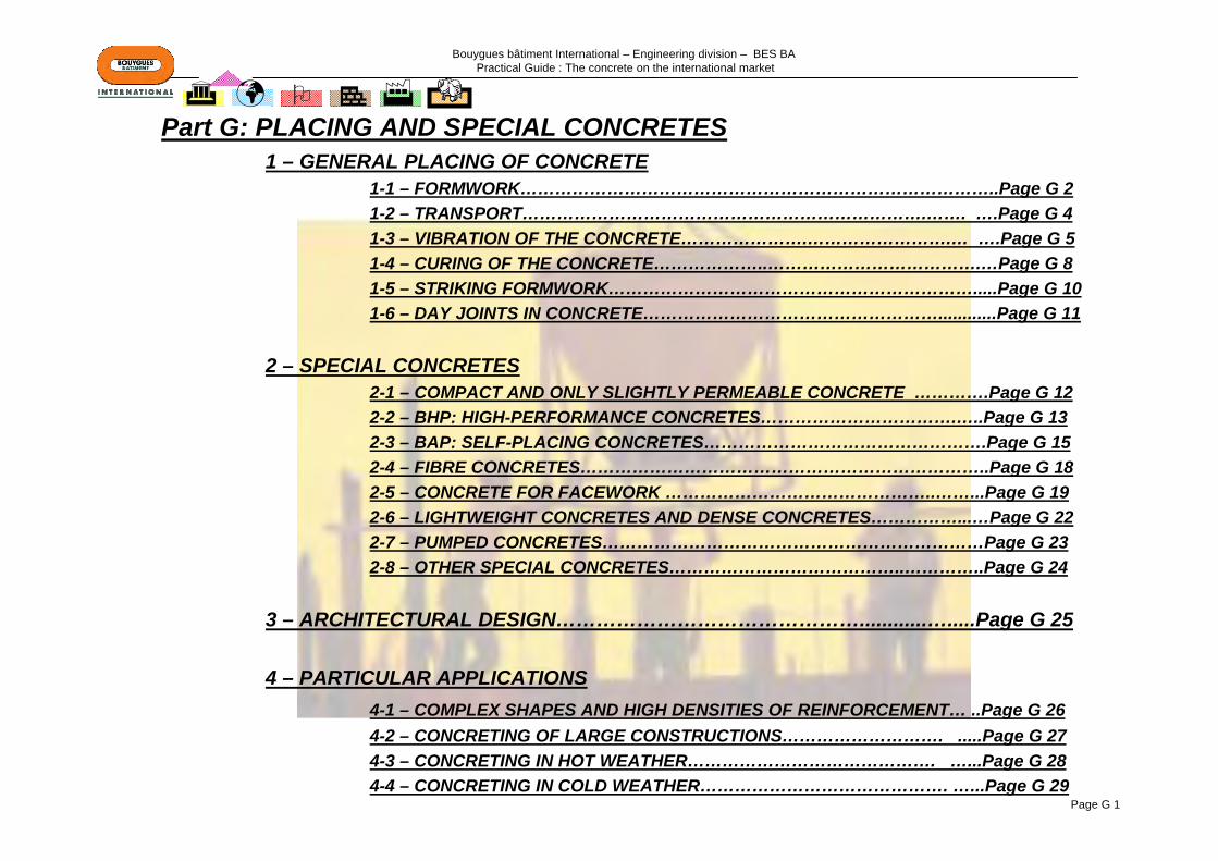
Bouygues bâtiment International – Engineering division – BES BA Practical Guide : The concrete on the international market
Page G 1
Part G: PLACING AND SPECIAL CONCRETES1 – GENERAL PLACING OF CONCRETE
1-1 – FORMWORK………………………………………………………………………..Page G 21-2 – TRANSPORT…………………………………………………………….……. ….Page G 41-3 – VIBRATION OF THE CONCRETE………………….…………………….… ….Page G 51-4 – CURING OF THE CONCRETE………………..……………………………….…Page G 81-5 – STRIKING FORMWORK……………………………………………………….....Page G 101-6 – DAY JOINTS IN CONCRETE……………………………………………............Page G 11
2 – SPECIAL CONCRETES2-1 – COMPACT AND ONLY SLIGHTLY PERMEABLE CONCRETE ………….Page G 122-2 – BHP: HIGH-PERFORMANCE CONCRETES…………………………….…..Page G 132-3 – BAP: SELF-PLACING CONCRETES………………………………………….Page G 152-4 – FIBRE CONCRETES……………………………………………………………..Page G 182-5 – CONCRETE FOR FACEWORK ………………………………………..……...Page G 192-6 – LIGHTWEIGHT CONCRETES AND DENSE CONCRETES……………...…Page G 222-7 – PUMPED CONCRETES…………………………………………………………Page G 232-8 – OTHER SPECIAL CONCRETES…………………………………..…………..Page G 24
3 – ARCHITECTURAL DESIGN………………………………………............….....Page G 25
4 – PARTICULAR APPLICATIONS4-1 – COMPLEX SHAPES AND HIGH DENSITIES OF REINFORCEMENT… ..Page G 264-2 – CONCRETING OF LARGE CONSTRUCTIONS………………………. .....Page G 274-3 – CONCRETING IN HOT WEATHER……………………………………. …...Page G 284-4 – CONCRETING IN COLD WEATHER……………………………………. …...Page G 29

Bouygues bâtiment International – Engineering division – BES BA Practical Guide : The concrete on the international market
Page G 2
Suitable for constructions of complex, non-repetitive shapes
Possible use to imitate timber facings
Use planks that are sufficiently thick (27 to 40 mm) made from species of timber free from tannin, dry and stabilised to prevent any warping
Modification of the characteristics of the timber as it is reused (lower porosity, surface wear) → influence on the surface colour and appearance
Speed of installation and assembly Possibility of reuse for units of a repetitive nature
(vertical walls, suspended floors)Encourage the dispersal of the heat caused by the
hydration of the cement → favourable criterion in hot weather
Smooth surface of the concreteVery suitable for external vibration if the design of the
formwork permits
Concrete less well protected against drops in temperature in cold weather (→ lagging of the formwork if necessary)
The main types of formwork
Timberformwork
Metalformwork
Formwork provides as its main functions:- moulding of the shape- moulding of the surface texture- maintaining stability until hardening- protection against drying out during setting and hardening
1 – GENERAL PLACING OF CONCRETE
1-1 – FORMWORK
Main componentsWhatever the nature of the formwork, there are always the same components:- A skin former which determines the final appearance (shape and texture) of the moulded item- A framework which limits deformation of the skin former (thrust of fresh concrete, self-weight of the concrete, etc.)- Spacer rods, struts for stability, props to enable the position of the formwork surfaces to be adjusted- Units built into the formwork or independent, to enable workers to work perfectly safely
bad
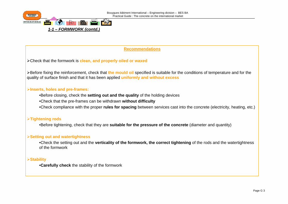
Bouygues bâtiment International – Engineering division – BES BA Practical Guide : The concrete on the international market
Page G 3
Recommendations
Check that the formwork is clean, and properly oiled or waxed
Before fixing the reinforcement, check that the mould oil specified is suitable for the conditions of temperature and for the quality of surface finish and that it has been applied uniformly and without excess
Inserts, holes and pre-frames:•Before closing, check the setting out and the quality of the holding devices•Check that the pre-frames can be withdrawn without difficulty•Check compliance with the proper rules for spacing between services cast into the concrete (electricity, heating, etc.)
Tightening rods•Before tightening, check that they are suitable for the pressure of the concrete (diameter and quantity)
Setting out and watertightness•Check the setting out and the verticality of the formwork, the correct tightening of the rods and the watertightness of the formwork
Stability•Carefully check the stability of the formwork
1-1 – FORMWORK (contd.)

Bouygues bâtiment International – Engineering division – BES BA Practical Guide : The concrete on the international market
Page G 4
1-2 – TRANSPORT
Recommendations to be followed during transport
The equipment used to transport the concrete must be cleaned frequently with water, in order not to introduce foreign bodies or rubbish into the concrete
The equipment must be such that the height that the concrete drops, as it is being placed, or the mechanical impacts as it is being handled, are not such as to create problems of segregation in the concrete
The time taken to transport the concrete must be limited, depending on the ambient temperature, humidity and wind conditions.For indicative purposes, in France, it must not exceed 1½ hours, as far as transport of ready-mixed concrete in a rotary mixer lorry is concerned. Concrete produced on site must be placed within 30 mins of production
In hot weather (T> 25°C), the use of retarded concrete is recommended, in order to prevent setting starting before placing is complete.
The concrete must be placed before it starts to set, otherwise it will lose strength and, in addition, there is a risk of extra water being added by the site in the mixer in order to restore its initial consistency, with all the risks that that includes. Setting may be more or less rapid, depending on the type of cement, the water content, the temperature of the fresh concrete and the type of additive.
The addition of water on delivery must not be permitted, due to the harmful effect of such additions on the strength of the concrete.For indicative purposes, the addition of 20 litres of water per m3 of concrete type C25/30 makes its strength drop by 5 MPa.
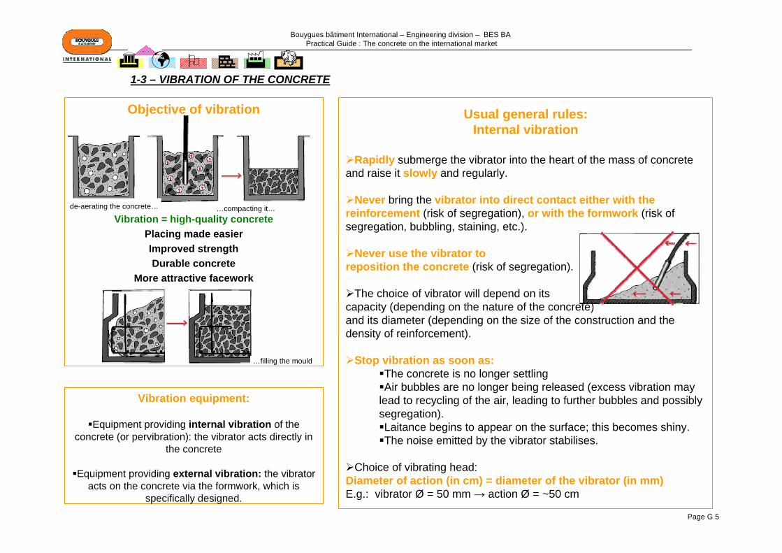
Bouygues bâtiment International – Engineering division – BES BA Practical Guide : The concrete on the international market
Page G 5
Usual general rules:Internal vibration
Rapidly submerge the vibrator into the heart of the mass of concrete and raise it slowly and regularly.
Never bring the vibrator into direct contact either with the reinforcement (risk of segregation), or with the formwork (risk of segregation, bubbling, staining, etc.).
Never use the vibrator to reposition the concrete (risk of segregation).
The choice of vibrator will depend on its capacity (depending on the nature of the concrete) and its diameter (depending on the size of the construction and the density of reinforcement).
Stop vibration as soon as:The concrete is no longer settlingAir bubbles are no longer being released (excess vibration may
lead to recycling of the air, leading to further bubbles and possibly segregation).Laitance begins to appear on the surface; this becomes shiny.The noise emitted by the vibrator stabilises.
Choice of vibrating head:Diameter of action (in cm) = diameter of the vibrator (in mm)E.g.: vibrator Ø = 50 mm → action Ø = ~50 cm
Objective of vibration
Vibration = high-quality concretePlacing made easierImproved strengthDurable concrete
More attractive facework
Vibration equipment:
Equipment providing internal vibration of the concrete (or pervibration): the vibrator acts directly in
the concrete
Equipment providing external vibration: the vibrator acts on the concrete via the formwork, which is
specifically designed.
1-3 – VIBRATION OF THE CONCRETE
de-aerating the concrete… …compacting it…
…filling the mould

Bouygues bâtiment International – Engineering division – BES BA Practical Guide : The concrete on the international market
Page G 6
Vibration of horizontal units: Suspended slabs, ground slabs, rafts
Do not slope the vibrator by more than 45°
Do not drag the head horizontally
Gaps between immersion points for the vibrator(s) identical to those for the vibration of vertical units.
Vibration of vertical units
External wall or cross wallVibration in layers 50 to 60 cm high of concretePenetration of the head into the layer immediately below by about 10 cmSpacing (e) between 2 points of vibration: e ~ 1.7 x radius of action of the vibrator
In situ concrete
Window in central opening:Vibration in layers of 50 cm on one side only (1) until concrete appears on the other side (2), and checking that the section underneath has been filled (3).
Opening for door or blank opening:
Columns and piersApplication of the above criteria, especially the thicknesses of the layers and day joints for a thickness of 10 to 15 cm into the layer below
If the reinforcement is too close together, provide a shaft of a suitable size for the passage of the vibrator, or consider external vibration.
1-3 – VIBRATION OF THE CONCRETE (contd.)
formworkformwork
Dia too large

Bouygues bâtiment International – Engineering division – BES BA Practical Guide : The concrete on the international market
Page G 7
Usual general rules:External vibration
May be usefully advised when the construction has tightly-packed reinforcement or very dry concrete, or if automationon the site is well developed.
Position the centre line of the vibrator perpendicularly to the strutsupporting the fixing system
Set the direction of rotation of the vibrator towards the formwork
Harmonise the vibrations of all the vibrators (speed of rotation, frequency, centrifugal force)
With external vibration, the compaction of the concrete is more homogenous than with internal vibration. Period of vibration andlaboriousness are reduced.
1-3 – VIBRATION OF THE CONCRETE (contd.)
Reminder In order to avoid the need to vibrate the
concrete, self-placing concrete, for example, should be used

Bouygues bâtiment International – Engineering division – BES BA Practical Guide : The concrete on the international market
Page G 8
Objectives of curingCuring enables the concrete to retain the water used in its composition so as to:
Obtain the specified compressive strength Improve durabilityEnsure the routine maintenance and finish of the concrete
The water will evaporate faster as the temperature increases,
as ambient humidity drops and as the wind
increases.(see figure opposite)
DANGER
1-4 – CURING OF THE CONCRETE
Example: Air temperature = 22°CConcrete temperature = 36°CRelative humidity = 90%Wind speed 5 kph → D=0.6 kg/m²/hr → OK22 kph → D=1.8 kg/m²/hr → Danger
Risks in the absence of curing•Open cracks (increased shrinkage)•Reduction in surface strength•Increase in the porosity of the surface concrete•Reduction in durability (corrosion of reinforcement, frost resistance, etc.)
A-Continual treatment against moistureB-In air after 28 days of wet curingC- n air after 7 days of curingD-Continually in air
A
B
C
D
Relative humidity (%)
Evaluation of levels of evaporation of moisture from the surface of concrete covered with water
Wind speed (km/h)
Concrete temperature (°C)
Air temperature (°C)
Leve
l of e
vapo
ratio
n (k
g (m
2/h)
)1- starting from air temperature, find the graph of relative humidity 2- move to the right up to concrete temperature3- move down to wind speed4- move to the left to read approx. level of evaporation
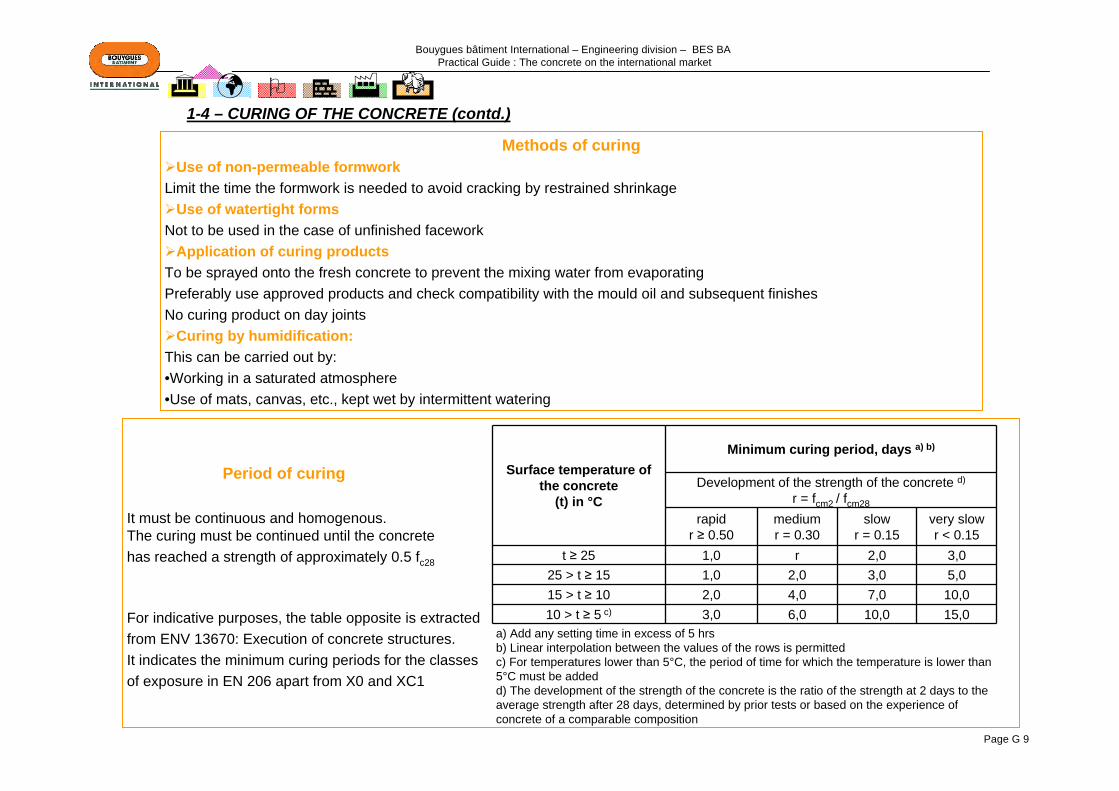
Bouygues bâtiment International – Engineering division – BES BA Practical Guide : The concrete on the international market
Page G 9
Methods of curingUse of non-permeable formwork
Limit the time the formwork is needed to avoid cracking by restrained shrinkage Use of watertight forms
Not to be used in the case of unfinished faceworkApplication of curing products
To be sprayed onto the fresh concrete to prevent the mixing water from evaporatingPreferably use approved products and check compatibility with the mould oil and subsequent finishesNo curing product on day joints
Curing by humidification:This can be carried out by:•Working in a saturated atmosphere•Use of mats, canvas, etc., kept wet by intermittent watering
Period of curing
It must be continuous and homogenous.The curing must be continued until the concretehas reached a strength of approximately 0.5 fc28
For indicative purposes, the table opposite is extracted from ENV 13670: Execution of concrete structures. It indicates the minimum curing periods for the classes of exposure in EN 206 apart from X0 and XC1
1-4 – CURING OF THE CONCRETE (contd.)
Surface temperature of the concrete
(t) in °C
Minimum curing period, days a) b)
Development of the strength of the concrete d)
r = fcm2 / fcm28
rapidr ≥ 0.50
mediumr = 0.30
slowr = 0.15
very slowr < 0.15
t ≥ 25 1,0 r 2,0 3,025 > t ≥ 15 1,0 2,0 3,0 5,015 > t ≥ 10 2,0 4,0 7,0 10,010 > t ≥ 5 c) 3,0 6,0 10,0 15,0
a) Add any setting time in excess of 5 hrsb) Linear interpolation between the values of the rows is permittedc) For temperatures lower than 5°C, the period of time for which the temperature is lower than 5°C must be addedd) The development of the strength of the concrete is the ratio of the strength at 2 days to the average strength after 28 days, determined by prior tests or based on the experience of concrete of a comparable composition

Bouygues bâtiment International – Engineering division – BES BA Practical Guide : The concrete on the international market
Page G 10
1-5 – STRIKING FORMWORK
For indicative purposes, in France, except in the case of the use of sliding forms or thermal treatments, striking is not carried out until the compressive strength of the concrete has reached a sufficient value of at least 5 MPa.
In average weather conditions (ambient temperature of 10° to 25°C, relative humidity greater than 60%), it can be estimated that this strength is reached 12 to 14 hrs after the end of placing.
This value will depend, in particular, on the nature of the cement, the amount used and on the shape of the construction.
Recommendations
Cold weather = slowing of hardening = keeping formwork and props for longer
Remove the formwork and the props progressively, without impact, without damaging the concrete, when the strength of the concrete is sufficient
Avoid overloading a floor slab locally during and after the striking of formwork; otherwise take it into account in the determination of the minimum strength
If there is a need for uniformity of colour for the facework, strike at constant maturity(same length of time and same actual strength on striking)
If the formwork forms an element of the curing system, the time prior to striking must be taken into account
The formwork and its props must not be dismantled until the concrete has achieved sufficient strength:•In order to withstand damage to the surface as the formwork is struck•In order to support the loads it has to carry at this stage•In order to avoid deflection that exceeds the specified tolerances

Bouygues bâtiment International – Engineering division – BES BA Practical Guide : The concrete on the international market
Page G 11
A "Day Joint" is formed where fresh concrete is poured in contact with old concrete, in order to ensure aesthetic or mechanical continuity between the two concretes.
Recommendations
General recommendations:The surface of the old concrete must be clean: dust, laitance, curing products and any mould release agents must be removed
by blowing with compressed air and/or with water under pressure The surface of the old concrete must not be covered with standing waterThe reinforcement must be stripped clean and correctly positionedThe vibration of the fresh concrete poured close to the surface of the old concrete must be carried out particularly
carefully
Precaution in hot weather: the surface of the old concrete must be protected from exposure to the sun and must be dampened regularly
Fresh concrete in a thin layer: The old concrete must be dampened particularly at the contact with the fresh concrete and particularly careful curing must be carried out after the new concrete is poured.
Day joint on a vertical or steeply sloping surface: the support must be cleaned in order to remove all traces of mould release agent. The support is generally prepared by blasting the surface with water under pressure or by blowing with air plus water. The roughness of the contact surface is given by the formwork for the concrete in the first phase.
Day joint on a horizontal surface. The support may be prepared by:- blowing with air plus water onto the fresh concrete just after setting begins- blasting the surface of the old concrete with water under pressure- sand blasting or blasting the old sound concrete with water at very high pressure
1-6 – DAY JOINTS

Bouygues bâtiment International – Engineering division – BES BA Practical Guide : The concrete on the international market
Page G 12
2 – The various types of CONCRETES
2-1 – COMPACT AND ONLY SLIGHTLY PERMEABLE CONCRETE
General definition
Suitable formulation Adequate cement content, sufficiently high (see example opposite)
•Low water content: use of additives (superplasticisers which enable large reductions of water content while maintaining excellent behaviour when placed, without reducing the plasticity and consistence of the mix)
•Particle size including a sufficient quantity of fine elements to fill the gaps between the larger aggregates. The increase in the extent of the granular skeleton by the use of ultrafine particles (silica fume, microfiller, limestone, etc.) will enable the compactness of the concrete to be increased even more
→ Low W/C ratio (<0.6)
Careful placing•Suitable and homogenous vibration (Page G 5)
•Effective curing to avoid excessive drying out of the concrete at a young age (Page G 8)
•Monitor temperature and humidity during placing and on the following days
Suitable design of the construction (Page G 25)
Avoid creating zones where water accumulates and stands and where surface water will create run-off channels
Example with a high quality C25/30
Sufficient quantity of fines Q (<80µm) ≥ 350 kg/m3 including at least 250
kg/m3 of CEM1Q (<160µm) ≥ 400 kg/m3Q (<315µm) ≥ 520 kg/m3
Fluid consistence (S4)Limited quantity of water (CEM 1 + additions E/Léq ≤
0.55 to 0.60) Reminder: Leq = binder equivalent = Cement + k Additions
(k depends on the type of cement and of the addition)Mixing continued for approximately 1 min after adding the
final ingredientClean and watertight formworkCorrect cover to reinforcementRelease agent (previously tested and a minimum quantity)No further water added after mixing in the mixing plantConcrete placed without a long waitDropping height limited to 1.50 mPlacing in horizontal strips approximately 40 to 60 cm highGood vibration
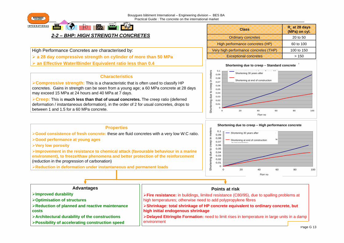
Bouygues bâtiment International – Engineering division – BES BA Practical Guide : The concrete on the international market
Page G 13
High Performance Concretes are characterised by:a 28 day compressive strength on cylinder of more than 50 MPa an Effective Water/Binder Equivalent ratio less than 0.4
CharacteristicsCompressive strength: This is a characteristic that is often used to classify HP
concretes. Gains in strength can be seen from a young age; a 60 MPa concrete at 28 days may exceed 15 MPa at 24 hours and 40 MPa at 7 days.
Creep: This is much less than that of usual concretes. The creep ratio (deferred deformation / instantaneous deformation), in the order of 2 for usual concretes, drops to between 1 and 1.5 for a 60 MPa concrete.
Class Rc at 28 days (MPa) on cyl.
Ordinary concretes 20 to 50
High performance concretes (HP) 60 to 100
Very high performance concretes (THP) 100 to 150Exceptional concretes > 150
PropertiesGood consistence of fresh concrete: these are fluid concretes with a very low W:C ratio.Good performance at young agesVery low porosityImprovement in the resistance to chemical attack (favourable behaviour in a marine
environment), to freeze/thaw phenomena and better protection of the reinforcement(reduction in the progression of carbonation)
Reduction in deformation under instantaneous and permanent loads
AdvantagesImproved durabilityOptimisation of structuresReduction of planned and reactive maintenance
costsArchitectural durability of the constructionsPossibility of accelerating construction speed
2-2 – BHP: HIGH STRENGTH CONCRETES
Racoourcissement du au fluage - Béton ordinaire
0
0,01
0,02
0,03
0,04
0,05
0,06
0,07
0,08
0,09
0,1
0 20 40 60 80 100
N° de l'étage
Rac
cour
ciss
emen
t de
fluag
e en
m
ètre
raccourcissement du au fluage 30ans aprèsraccourcissement du au fluage à lafin de la construction
Racourcissement du au fluage - BHP
00,010,020,030,040,050,060,070,080,090,1
0 20 40 60 80 100
N° de l'étage
Rac
cour
ciss
emen
t de
fluag
e en
m
ètre
raccourcissement du au fluage 30 ansaprès
raccourcissemnt du au fluage à la fin dela construction
Points at riskFire resistance: in buildings, limited resistance (C80/95), due to spalling problems at
high temperatures; otherwise need to add polypropylene fibres Shrinkage: total shrinkage of HP concrete equivalent to ordinary concrete, but
high initial endogenous shrinkage Delayed Ettringite Formation: need to limit rises in temperature in large units in a damp
environment
Shortening due to creep – Standard concrete
Shortening due to creep – High performance concrete
Sho
rteni
ng d
ue to
cre
ep in
met
ers
Sho
rteni
ng d
ue to
cre
ep in
met
ers
Shortening 30 years after
Shortening at end of construction
Shortening 30 years after
Shortening at end of construction
Florr no
Florr no
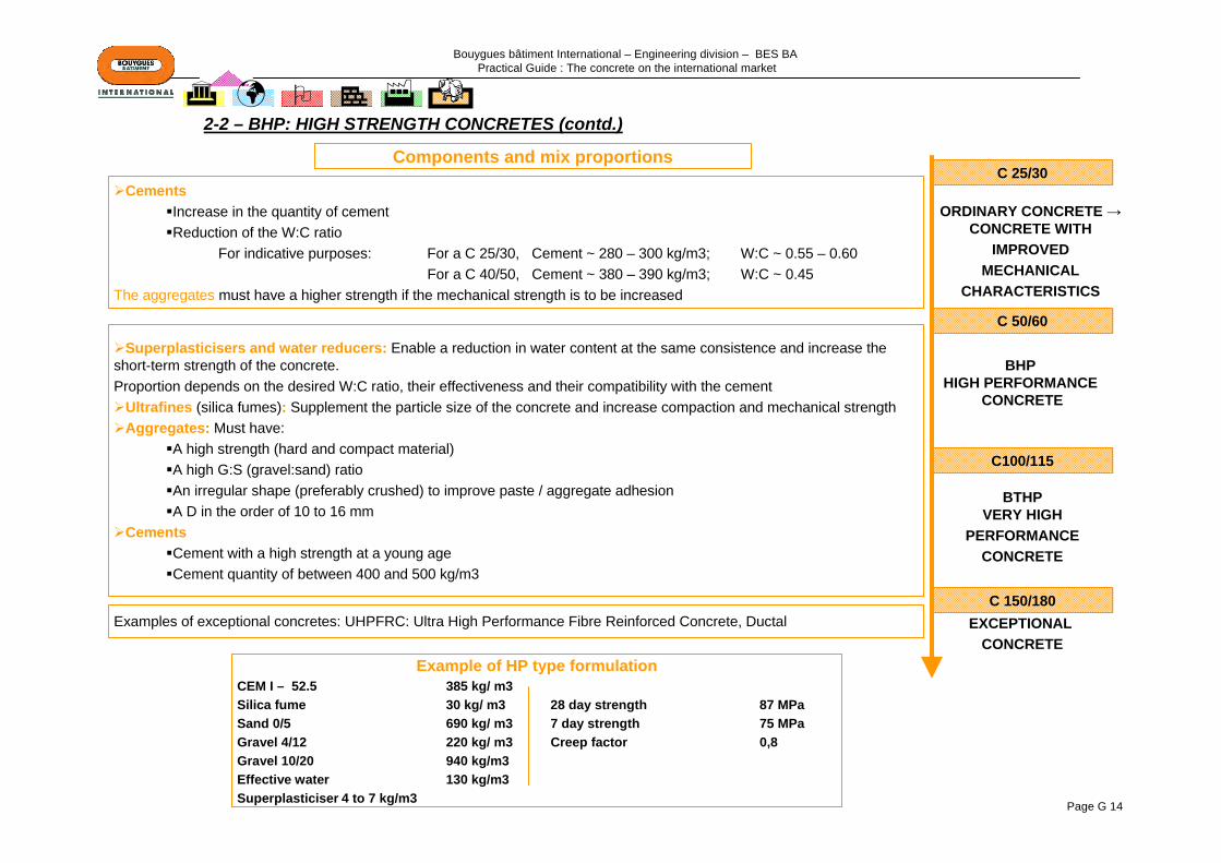
Bouygues bâtiment International – Engineering division – BES BA Practical Guide : The concrete on the international market
Page G 14
Superplasticisers and water reducers: Enable a reduction in water content at the same consistence and increase the short-term strength of the concrete. Proportion depends on the desired W:C ratio, their effectiveness and their compatibility with the cement
Ultrafines (silica fumes): Supplement the particle size of the concrete and increase compaction and mechanical strengthAggregates: Must have:
A high strength (hard and compact material)A high G:S (gravel:sand) ratioAn irregular shape (preferably crushed) to improve paste / aggregate adhesionA D in the order of 10 to 16 mm
CementsCement with a high strength at a young ageCement quantity of between 400 and 500 kg/m3
2-2 – BHP: HIGH STRENGTH CONCRETES (contd.)
C 25/30
C100/115
C 50/60
C 150/180
ORDINARY CONCRETE →CONCRETE WITH
IMPROVEDMECHANICAL
CHARACTERISTICS
BHP HIGH PERFORMANCE
CONCRETE
BTHPVERY HIGH
PERFORMANCECONCRETE
EXCEPTIONAL CONCRETE
CementsIncrease in the quantity of cementReduction of the W:C ratio
For indicative purposes: For a C 25/30, Cement ~ 280 – 300 kg/m3; W:C ~ 0.55 – 0.60For a C 40/50, Cement ~ 380 – 390 kg/m3; W:C ~ 0.45
The aggregates must have a higher strength if the mechanical strength is to be increased
Examples of exceptional concretes: UHPFRC: Ultra High Performance Fibre Reinforced Concrete, Ductal
Components and mix proportions
Example of HP type formulation CEM I – 52.5 385 kg/ m3Silica fume 30 kg/ m3 28 day strength 87 MPaSand 0/5 690 kg/ m3 7 day strength 75 MPaGravel 4/12 220 kg/ m3 Creep factor 0,8Gravel 10/20 940 kg/m3Effective water 130 kg/m3Superplasticiser 4 to 7 kg/m3

Bouygues bâtiment International – Engineering division – BES BA Practical Guide : The concrete on the international market
Page G 15
Self-placing concrete is characterised by its hyperfluidity, meaning that it can be placed by gravity, without the need for vibration.
PropertiesVery fluid and pumpableAbsolutely homogenousPlacing without vibration and without impactHas similar strength and durability to those of traditional concretes and of high-performance concretes
ConsequencesProductivity improvements
Rapidity of placingImproved construction speedReduction in maintenance costs
Saving of labour Reduced placing timeLimited making good
Improvement in working and environmental conditions Difficulty of tasks Site safetyReduced noise problems
Improvement in the quality of facework
Other terms defining this concrete:Self-levelling concreteSelf-compacting concrete: SCCHyper-fluid concrete
Points at riskFormulation:
Water content must be closely controlled Continuous particle size (otherwise risk of bleeding)
Not negligible additional cost Setting delayed in cold weather (if no precautions)Increased thrust in formwork
2-3 – BAP: SELF-PLACING CONCRETES
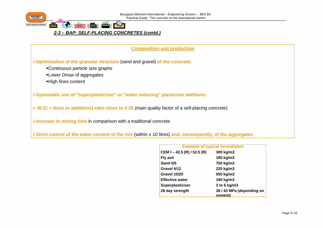
Bouygues bâtiment International – Engineering division – BES BA Practical Guide : The concrete on the international market
Page G 16
Composition and production
Optimisation of the granular structure (sand and gravel) of the concrete:Continuous particle size graphsLower Dmax of aggregatesHigh fines content
Systematic use of "superplasticiser" or "water reducing" plasticiser additives
W:(C + fines or additions) ratio close to 0.35 (main quality factor of a self-placing concrete)
Increase in mixing time in comparison with a traditional concrete
Strict control of the water content of the mix (within ± 10 litres) and, consequently, of the aggregates
2-3 – BAP: SELF-PLACING CONCRETES (contd.)
Example of typical formulation CEM I – 42.5 (R) / 52.5 (R) 300 kg/m3Fly ash 180 kg/m3Sand 0/5 750 kg/m3Gravel 4/12 220 kg/m3Gravel 10/20 650 kg/m3Effective water 190 kg/m3Superplasticiser 3 to 6 kg/m328 day strength 38 / 43 MPa (depending on
cement)

Bouygues bâtiment International – Engineering division – BES BA Practical Guide : The concrete on the international market
Page G 17
Recommendations for placing:
Specific site preparation and organisation: self-placing concretes require a change of habits and the adaption of traditional construction methods: plant – staff – construction phasing – rigorous wedging of the reinforcement and of inserts to form holes
Use of clean, watertight and stronger formwork in order to compensate for the hydrostatic thrust on the formwork.In typical uses (walls 2.8 m high), the thrust during placing does not exceed the strength limits of the formwork. In the case of walls of great height and/or with very many openings, the formwork must be specially designed.
Falls: limit falls to 2%Use of suitable mould release products in order to avoid the phenomena of micro-bubblingCareful curing: as these concretes are more sensitive to the phenomena of shrinkage due to drying out (particularly horizontal
surfaces)
As for all concretes, it is necessary, during the concreting phases, to take the weather conditions into account and to implement particular arrangements outside the temperature range (+5°C to 35°C)
Placing with a traditional mixer and discharge pipeThe concrete is placed from the top of the formwork by means of a discharge pipe. The pipe is slid into the formwork in order tolimit the drop height. The diameter of the pipe under the mixer drum has to be adapted in comparison with traditional concrete (60 to 80 mm diameter instead of 150 to 200 mm diameter) so that it can be inserted between the reinforcement.
Placing by pumping from the bottom of the formwork: "source" pumpingThis method is suitable, in particular, for vertical units of great height. It avoids the need for working at the top of the formwork.
Placing by pumping at the top of the formwork with a plunger tube The plunger tube must be inserted far enough into the formwork to limit the dropping height as much as possible.
2-3 – BAP: SELF-PLACING CONCRETES (contd.)
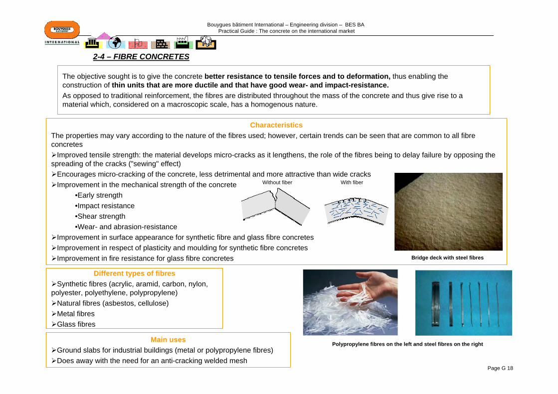
Bouygues bâtiment International – Engineering division – BES BA Practical Guide : The concrete on the international market
Page G 18
The objective sought is to give the concrete better resistance to tensile forces and to deformation, thus enabling the construction of thin units that are more ductile and that have good wear- and impact-resistance.As opposed to traditional reinforcement, the fibres are distributed throughout the mass of the concrete and thus give rise to a material which, considered on a macroscopic scale, has a homogenous nature.
CharacteristicsThe properties may vary according to the nature of the fibres used; however, certain trends can be seen that are common to all fibre concretes
Improved tensile strength: the material develops micro-cracks as it lengthens, the role of the fibres being to delay failure by opposing the spreading of the cracks ("sewing" effect)
Encourages micro-cracking of the concrete, less detrimental and more attractive than wide cracksImprovement in the mechanical strength of the concrete
•Early strength•Impact resistance •Shear strength•Wear- and abrasion-resistance
Improvement in surface appearance for synthetic fibre and glass fibre concretesImprovement in respect of plasticity and moulding for synthetic fibre concretesImprovement in fire resistance for glass fibre concretes
Different types of fibresSynthetic fibres (acrylic, aramid, carbon, nylon,
polyester, polyethylene, polypropylene)Natural fibres (asbestos, cellulose)Metal fibresGlass fibres
2-4 – FIBRE CONCRETES
Main usesGround slabs for industrial buildings (metal or polypropylene fibres)Does away with the need for an anti-cracking welded mesh
Polypropylene fibres on the left and steel fibres on the right
Bridge deck with steel fibres
Without fiber With fiber
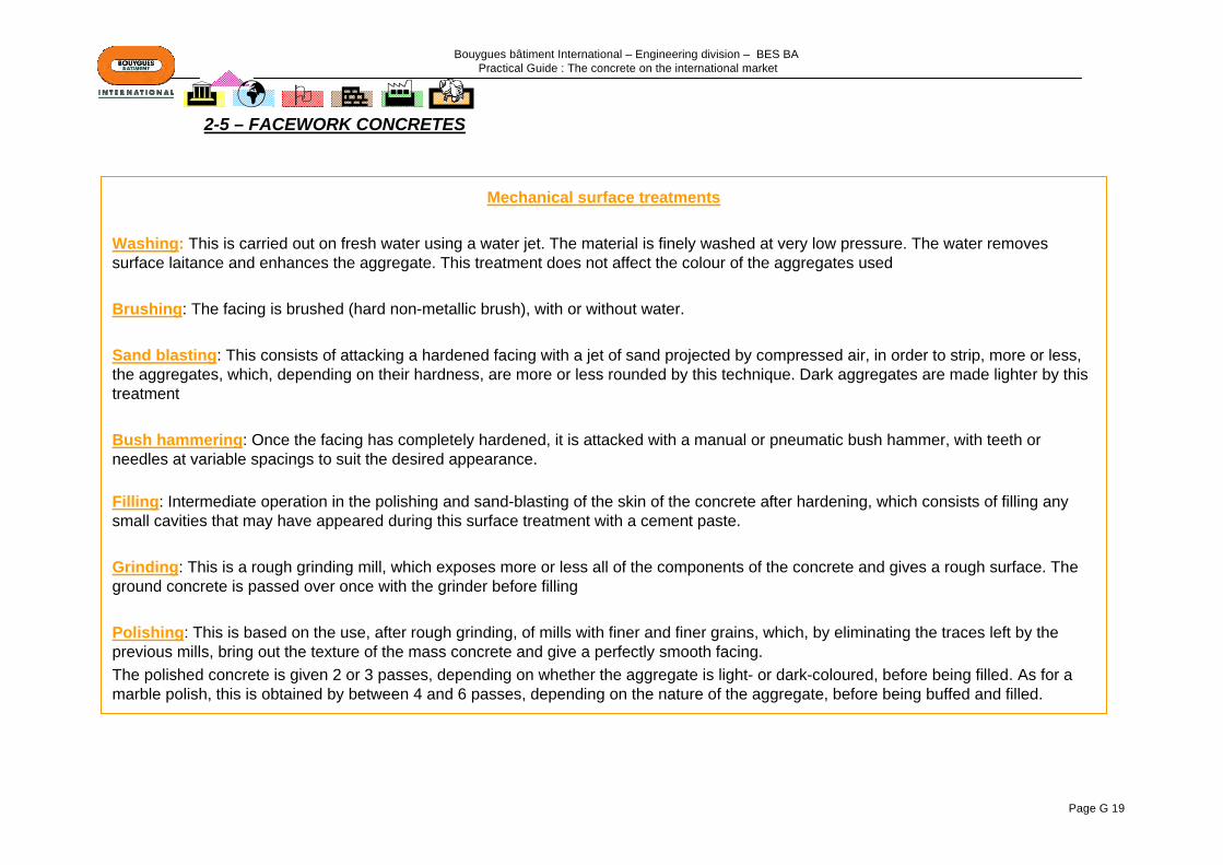
Bouygues bâtiment International – Engineering division – BES BA Practical Guide : The concrete on the international market
Page G 19
Mechanical surface treatments
Washing: This is carried out on fresh water using a water jet. The material is finely washed at very low pressure. The water removes surface laitance and enhances the aggregate. This treatment does not affect the colour of the aggregates used
Brushing: The facing is brushed (hard non-metallic brush), with or without water.
Sand blasting: This consists of attacking a hardened facing with a jet of sand projected by compressed air, in order to strip, more or less, the aggregates, which, depending on their hardness, are more or less rounded by this technique. Dark aggregates are made lighter by this treatment
Bush hammering: Once the facing has completely hardened, it is attacked with a manual or pneumatic bush hammer, with teeth or needles at variable spacings to suit the desired appearance.
Filling: Intermediate operation in the polishing and sand-blasting of the skin of the concrete after hardening, which consists of filling any small cavities that may have appeared during this surface treatment with a cement paste.
Grinding: This is a rough grinding mill, which exposes more or less all of the components of the concrete and gives a rough surface. Theground concrete is passed over once with the grinder before filling
Polishing: This is based on the use, after rough grinding, of mills with finer and finer grains, which, by eliminating the traces left by the previous mills, bring out the texture of the mass concrete and give a perfectly smooth facing.The polished concrete is given 2 or 3 passes, depending on whether the aggregate is light- or dark-coloured, before being filled. As for a marble polish, this is obtained by between 4 and 6 passes, depending on the nature of the aggregate, before being buffed and filled.
2-5 – FACEWORK CONCRETES

Bouygues bâtiment International – Engineering division – BES BA Practical Guide : The concrete on the international market
Page G 20
2-5– FACEWORK CONCRETES (contd.)
Colouring of the concrete
Through-colouring: The general colour of the concrete can be modified by adding pigments. Mineral pigments, the only pigments that can be used in concretes, are capable of absorbing part of the white light that they receive, by only reflecting the fraction corresponding to their colour. Some of these pigments can be found in nature, whence their name of natural pigments (e.g.: oxides of certain minerals, such as iron, chromium, titanium, cobalt, etc.).Depending on their particle size, pigments of an identical colour have different colouring powers. This must be taken into account in the quantity used.
Paint: This is a traditional means of adding colour to concrete. By hiding the background material, the paint substantially modifies its appearance.
Stains: Neither paints nor varnishes, stains for concrete are acrylic polymers in solution, which colour the concrete and enhance it without concealing it. Stains protect the concrete from water – while allowing dirt to wash off – and from attack by carbon dioxide and sulphates.
Chemical surface treatments
Deactivation: This is based on the use of a setting retarder deactivator, applied to the formwork before the concrete is placed, which delays its setting on the surface. The skin of the concrete may also be removed by washing with a jet of water, followed by brushing.
Acid etching: This consists of attacking the facing of hardened concrete with a solution based on hydrochloric acid. The depth of the attack varies according to the concentration of the solution and the length of time of the treatment. This must be followed by washing with a large quantity of water in order to avoid the depassivation of the concrete and the corrosion of the reinforcement. It is used only on siliceous aggregates

Bouygues bâtiment International – Engineering division – BES BA Practical Guide : The concrete on the international market
Page G 21
2-5– FACEWORK CONCRETES (contd.)
Washed beige Washed ochre Washed blue Washed green Washed grey Washed black
bush-hammered beige bush-hammered ochre bush hammered blue bush hammered green bush hammered grey bush hammered black
sand-blasted beige sand-blasted ochre sand-blasted blue sand-blasted green sand-blasted grey sand-blasted black
polished beige polished ochre polished blue polished green polished grey polished black
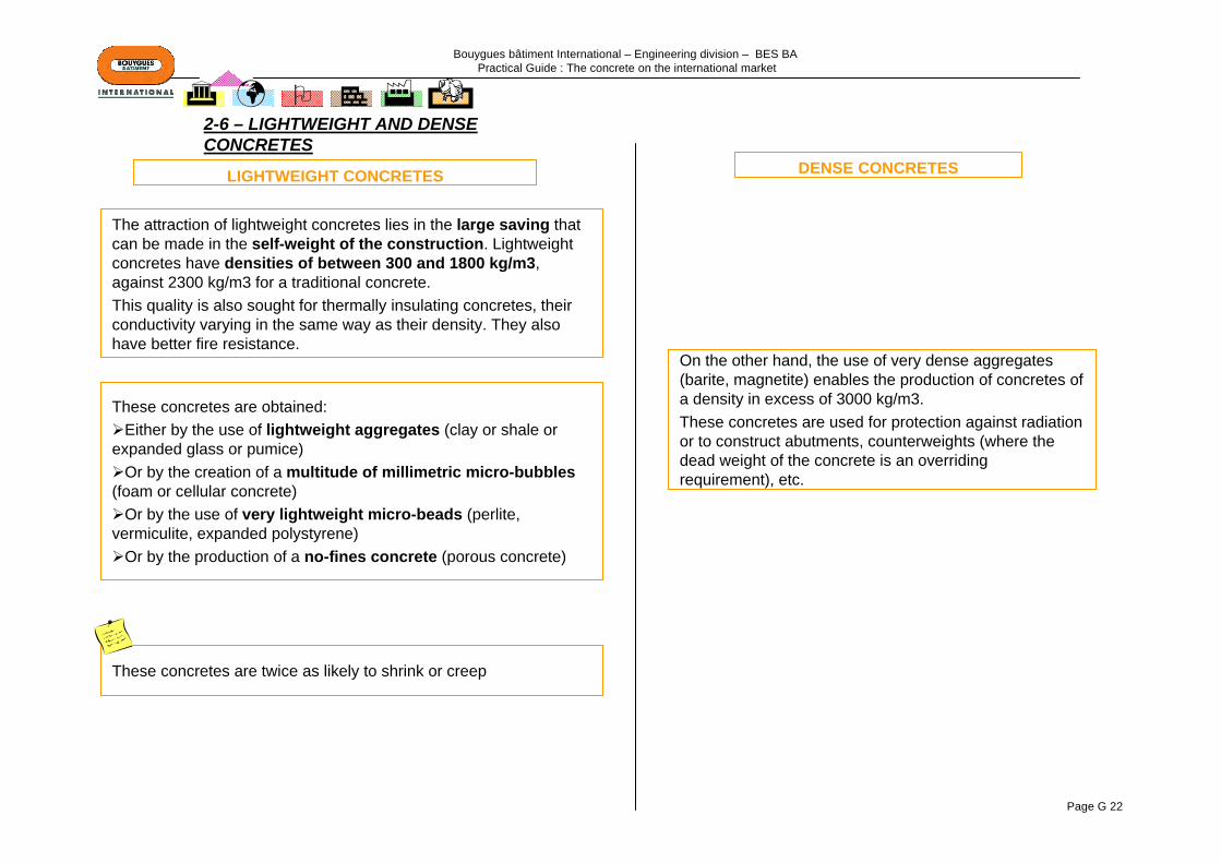
Bouygues bâtiment International – Engineering division – BES BA Practical Guide : The concrete on the international market
Page G 22
The attraction of lightweight concretes lies in the large saving that can be made in the self-weight of the construction. Lightweight concretes have densities of between 300 and 1800 kg/m3, against 2300 kg/m3 for a traditional concrete. This quality is also sought for thermally insulating concretes, their conductivity varying in the same way as their density. They alsohave better fire resistance.
These concretes are obtained:Either by the use of lightweight aggregates (clay or shale or
expanded glass or pumice)Or by the creation of a multitude of millimetric micro-bubbles
(foam or cellular concrete)Or by the use of very lightweight micro-beads (perlite,
vermiculite, expanded polystyrene)Or by the production of a no-fines concrete (porous concrete)
These concretes are twice as likely to shrink or creep
On the other hand, the use of very dense aggregates (barite, magnetite) enables the production of concretes of a density in excess of 3000 kg/m3.These concretes are used for protection against radiation or to construct abutments, counterweights (where the dead weight of the concrete is an overriding requirement), etc.
LIGHTWEIGHT CONCRETES DENSE CONCRETES
2-6 – LIGHTWEIGHT AND DENSE CONCRETES

Bouygues bâtiment International – Engineering division – BES BA Practical Guide : The concrete on the international market
Page G 23
2-7 – PUMPED CONCRETES
Concrete transported by pipework and not in a lorry. This process for delivering concrete is pushed through tubes from a supply hopper to the location of placing. It enables horizontal distances of up to 400 m (or even 1.5 km) and vertical distances of 100 m (or even 300 m) to be covered. The typical flow rate of the pumps varies between 8 m3/hr and 70 m3/hr. It may reach 160 m3/hr on large items.
Points at risk Ensure a constant supply of fresh concrete (pump hopper always loaded, in order to maintain the homogeneity of the
concrete)Check that a constant flow rate is maintained in the supply pipes and clean the pipes at the end of each operationPumping through vertical, angled or flexible pipes considerably reduces the maximum pumping distance
AdvantagesLiberation of the craneAccess to difficult locationsTransport over great distancesContinuous supply of fresh concreteImproved construction speed
RecommendationsFormulation of the concrete
Fines content (including cement) must be in the order of:-400 to 420 kg/m3 for fines less than 0.160 mm-350 kg/m3 for fines less than 0.080 mmAggregates:
- if possible rolled- particle size as continuous as possible- the diameter of the coarsest gravels must be less than one quarter of the diameter of the pipesAdditive: : if possible, add a plasticiser to reduce W:C; add a superplasticiser for a slump greater
than 15 cmThe consistence of the concrete must be plastic: cone slump between 5 and 15 cm
PlantEquivalent transport distance = D + 5xH + 10xC1 + 5xC2 (in m) where D: horizontal distance in m,
H: difference in level in m upwards; C1: number of 90° bends; C2: number of 135° bendsProtect the pipework from the sun in hot weather (light colour, watering, etc.) or use of a setting
retarderProvide a straight length of at least 4 m at the outlet from the pumpAt the beginning of the operation, it is recommended to send "lubricating mortar" through the pipe,
which, as a general rule, is not used in the construction Floor slab: tilt the end of the pipe upwards (see photograph above)
Principle
Pumping through a flexible tube is carried out by crushing a flexible tube between rubber rollers, driven by a chain or a rotor. This system is used for pumping over short distances (length 50 m, difference in level 10 m) and for flow rates in the order of 15 m3/hr.
Piston pumps comprise two pistons working in opposition. One cylinder pushes the concrete into the tubes while the other sucks the content of the supply hopper. A distribution system using a swivelling tube ensures continuity of pumping.
Characteristics and sizing of the pump
For a given manufacturer, the choice will depend:-On the flow rate of the concrete in m3 per hour-On the diameter of the distribution pipes-On the length of the pipes and the height to be raised-On the consistence of the concrete to be used

Bouygues bâtiment International – Engineering division – BES BA Practical Guide : The concrete on the international market
Page G 24
2-8 – OTHER SPECIAL CONCRETES…
UNDERWATER CONCRETES
Concrete placed under water and, therefore, poured in the presence of water pressure, for which allowance must be made when carrying out the worksThe composition of this concrete must be studied very carefully, using, in particular, water-repellent colloidal agents that increase the forces of attraction between particles and, thus, the cohesion of the concrete
NO-FINES CONCRETES
Concrete obtained by the omission or very great reduction of fine aggregate: it is therefore the product of a mixture of coarse aggregates and cement paste.No-fines concrete is used particularly for insulation.
ULTRA-HIGH-PERFORMANCE FIBRE-REINFORCED CONCRETE - DUCTAL
Fibre-reinforced concrete with exceptional levels of performance (very great consistence, very high compressive strengths – 150 to 200 MPa - , very great durability).Their formulations require specific superplasticiser additives, specific aggregates, ultrafine particles and fibres.
SPRAYED CONCRETES
Concrete sprayed, after mixing either wet or dry, onto a background in the form of a jet, in successive layers. It enables the most complex shapes to be formed (domes, shells, etc.). It is also often used in underground works.
REFRACTORY CONCRETES
Concretes capable of withstanding continuous very high temperatures of up to 1600°C, whereas a traditional concrete "lets go" at 300°C. An aluminous cement with a high alumina content must be used in the formulation, together with refractory aggregates.

Bouygues bâtiment International – Engineering division – BES BA Practical Guide : The concrete on the international market
Page G 25
A properly adapted design of the construction will avoid the formation of zones where water can collect and stand and of locations where surface water will create run-off channels
Avoid traps where water can collect (hollows, projections, etc.)Prevent water running down the construction (drips, cornices, flashings, etc.)…
3 – ARCHITECTURAL DESIGN (a few examples)
Joinery profile to form weather
drip
Joinery or face of wall
Outside face inside face
slope
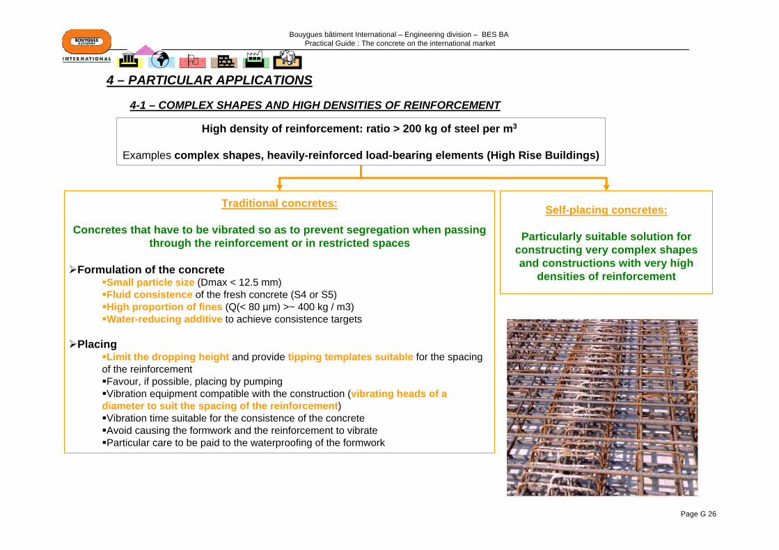
Bouygues bâtiment International – Engineering division – BES BA Practical Guide : The concrete on the international market
Page G 26
High density of reinforcement: ratio > 200 kg of steel per m3
Examples complex shapes, heavily-reinforced load-bearing elements (High Rise Buildings)
Traditional concretes:
Concretes that have to be vibrated so as to prevent segregation when passing through the reinforcement or in restricted spaces
Formulation of the concreteSmall particle size (Dmax < 12.5 mm)Fluid consistence of the fresh concrete (S4 or S5)High proportion of fines (Q(< 80 µm) >~ 400 kg / m3)Water-reducing additive to achieve consistence targets
PlacingLimit the dropping height and provide tipping templates suitable for the spacing
of the reinforcementFavour, if possible, placing by pumpingVibration equipment compatible with the construction (vibrating heads of a
diameter to suit the spacing of the reinforcement)Vibration time suitable for the consistence of the concreteAvoid causing the formwork and the reinforcement to vibrateParticular care to be paid to the waterproofing of the formwork
Self-placing concretes:
Particularly suitable solution for constructing very complex shapes and constructions with very high
densities of reinforcement
4 – PARTICULAR APPLICATIONS
4-1 – COMPLEX SHAPES AND HIGH DENSITIES OF REINFORCEMENT
Bouygues bâtiment International – Engineering division – BES BA Practical Guide : The concrete on the international market
Page G 27
Objectives:
To limit the maximum temperature of the concrete during its hardening phase (do not exceed 65 to 70°C for Portland-based cements
To limit the thermal gradient generally to 20°C, between the skin and the core of the concrete in order to avoid any danger of cracking
Recommendations
Favour cements with a low heat of hydration
Measure the heat in the core of the concrete using sensors
In summer, lower the initial temperature of the concrete by using ice in the mixing water and by watering the aggregates
Preferably use aggregates with a high Dmax in order to limit the quantity of cement
Protect the skin of the concrete (curing) from the thermal shocks that may be caused by the external environment
If the thermal gradient is well in excess of 20°C, provide the necessary reinforcement to absorb the thermal forces and to limit the danger of cracking.
Importance of the choice of cement in the construction of a raft in hot weather:For a large construction with a fresh concrete temperature on delivery = 25°C, cement content 350 kg/m3
Example 1: cement CEM I 52.5 N CE CP2 NF → Tmax = ~ 70°C (T calculated at 2 days in the core of the mass) → To be avoidedExample 2: cement CEM III/C 32.5 N CE PM ES NF → Tmax = ~ 45°C (T calculated at 2 days in the core of the mass) →OK
4-2 – CONCRETING OF LARGE CONSTRUCTIONS
Bouygues bâtiment International – Engineering division – BES BA Practical Guide : The concrete on the international market
Page G 28
RecommendationsRecommendations relating to formulation
Preferably use a cement with a low hydration heat and avoid a cement with rapid developmentNever add extra water in excess of the formulationAdd a plasticiser, if necessary, or a water-reducing superplasticiserAdd a setting retarder
Recommendations for production and transportProtect the water, the cement and the aggregates from the sun as much as possiblePreferably use the aggregates in the morning, after they have cooled down at night, or cool them before use by watering them (in this
case, allow for the additional water)Use cold waterIf supply is from a ready-mix plant, take steps to limit the temperature of the fresh concrete on departure, reduce transport and waiting
time and limit the time the mixer lorries spend parking in full sun.
Recommendations for concretingAdapt the times for concreting according to the temperature (coolest times of the day)Carry out placing as quickly as possibleDo not add water to try and improve the consistence of the concrete Protect the formwork (in particular metal formwork) from direct sunlight and, possibly, cool it by wetting it before concreting
Protection of the concretesProtect from evaporation immediately after placing, particularly surfaces exposed to the sun and to the wind, using a curing product,
by a tarpaulin (wet mats, polyethylene film, etc.) or by using a water spraying system.Maintain the protection for the first few hours, or even a few days, depending on how the weather changesProvide all arrangements to enable the heat to escape so as to keep the concrete at an acceptable temperature (protection from sunlight,
frequent watering of the formwork, etc.).
When young, concrete is sensitive to heat. A rise in temperature accelerates setting and hardening, causes the evaporation of the mixing
water and may therefore have an unfavourable effect on the characteristics of the hardened concrete.
As a general rule, as soon as the temperature measured on site
(temperature taken in the shade, 1.50 m above the ground) is sustainably
greater than 25°C, previously defined
particular arrangementsmust be taken for
concreting.
Above 35°C, as far as possible, concreting
should be deferred to a more favourable period.
4-3 – CONCRETING IN HOT WEATHER

Bouygues bâtiment International – Engineering division – BES BA Practical Guide : The concrete on the international market
Page G 29
Cold and frost may have harmful consequences on the quality and the levels of performance of the concrete
At an external temperature of 5°C:
The setting time is in the order of 10 hrs against 2.30 hrs at 20°C.
The compressive strengths at 2 days are in the order of 2 MPa against 15 to 20 MPa at 20°C
On site, the temperature must be measured regularly, as it conditions the steps to be taken. The site thermometer must be positioned 1.50 m above ground level, sheltered from rain and sun.
Below a temperature of 5°C, setting may be sufficiently affected to change the development of the hydration reaction.
The hydration kinetics stop as soon as the temperature of the concrete drops below 0°C.
The time after placing before the concrete is "frost-proof" is in the order of 3 days at a temperature of at least 5°C. A concrete subjected to frost within this time is practically irrecoverable, whereas, after that time, the cold only causes hardening to slow down.
4-4 – CONCRETING IN COLD WEATHER
Seen in a microscope, traces of frost in the paste of a fresh concrete. The ice crystals
form as the fresh concrete freezes
Time before striking formwork versus temperature Start of concrete setting versus temperature
(compressive strength in MpA)
Minimum striking time
timeStart of setting
Bouygues bâtiment International – Engineering division – BES BA Practical Guide : The concrete on the international market
Page G 30
Recommendations
Recommendations relating to formulationPreferably use rapid-hardening cements, with high hydration heat and high early strengthIf necessary, increase the quantity of cementReduce the quantity of water by using suitable additives: water reducers, setting accelerators,
hardening acceleratorsCarry out prior studies of cement/additive compatibility under conditions close to those of the site.
Recommendations to create and maintain a quantity of heat in the fresh concreteUse heated mixing water and maintain the temperature after placing by heating the formworkStore the aggregates in a frost-free place and, in an extreme case, possibly heat them before
adding them to the mixing plantIf possible, use formwork that has insulation (lagging)
(namely: timber formwork more insulating than metal formwork)Reduce the transport time between the concrete production plant and the site by as much as possible
and place the concrete in the formwork as quickly as possible If the water temperature > 60°C, modify the way the components are added to the mixer so that the
water is not directly in contact on its own with the cement
Maintain the protective devicesKeep the concrete warm, if possible, as it hardens, by using insulating tarpaulins and by adding heatProtect the surface of the concrete in contact with air from cold (for example: insulating tarpaulin,
insulation boards) and, more especially, units that are not very thickKeep the concrete at a minimum temperature of between 15 and 20°C (never dropping, especially,
below 5°C) during its setting and its initial hardening (use of electric heaters for example)
Recommendations for striking formworkKeep the surface protection for at least 72 hrsOnly strike the formwork if the concrete has reached sufficient minimum strength in the order of
5 MPa to 10 MPa so as to be able to withstand subsequent forces during the following phases of concreting.
An increase in the temperature of the components of the concrete may raise its temperature, for example:
An increase of 10°C of the water raises the temperature of the concrete by 2°C
An increase of 10°C of the aggregates raises the temperature of the concrete by 7°C
An increase of 10°C of the cement raises the temperature of the concrete by 1°C
4-4 – CONCRETING IN COLD WEATHER (contd.)