
High Tech Concrete: Where Technology and Engineering Meet · High Tech Concrete: Where Technology...
11
High Tech Concrete: Where Technology and Engineering Meet
Transcript of High Tech Concrete: Where Technology and Engineering Meet · High Tech Concrete: Where Technology...

High Tech Concrete:Where Technology and Engineering Meet

D.A. Hordijk • M. LukovićEditors
High Tech Concrete:Where Technologyand Engineering MeetProceedings of the 2017 fib Symposium,held in Maastricht, The Netherlands,June 12–14, 2017
123

EditorsD.A. HordijkDelft University of TechnologyDelftThe Netherlands
M. LukovićDelft University of TechnologyDelftThe Netherlands
ISBN 978-3-319-59470-5 ISBN 978-3-319-59471-2 (eBook)DOI 10.1007/978-3-319-59471-2
Library of Congress Control Number: 2017942981
© Springer International Publishing AG 2018This work is subject to copyright. All rights are reserved by the Publisher, whether the whole or partof the material is concerned, specifically the rights of translation, reprinting, reuse of illustrations,recitation, broadcasting, reproduction on microfilms or in any other physical way, and transmissionor information storage and retrieval, electronic adaptation, computer software, or by similar or dissimilarmethodology now known or hereafter developed.The use of general descriptive names, registered names, trademarks, service marks, etc. in thispublication does not imply, even in the absence of a specific statement, that such names are exempt fromthe relevant protective laws and regulations and therefore free for general use.The publisher, the authors and the editors are safe to assume that the advice and information in thisbook are believed to be true and accurate at the date of publication. Neither the publisher nor theauthors or the editors give a warranty, express or implied, with respect to the material contained herein orfor any errors or omissions that may have been made. The publisher remains neutral with regard tojurisdictional claims in published maps and institutional affiliations.
Cover picture: Bridge De Lentloper, Nijmegen, the Netherlands, by Thea van den Heuvel/DAPh.
Printed on acid-free paper
This Springer imprint is published by Springer NatureThe registered company is Springer International Publishing AGThe registered company address is: Gewerbestrasse 11, 6330 Cham, Switzerland
Steel- Concrete- Composite Bridgeswith Innovative Prefabricated Slab Elements
Kerstin Fuchs(&), Georg Gaßner, and Johann Kollegger
Institute of Structural Engineering, TU Wien,Karlsplatz 13, 1040 Vienna, Austria
{kerstin.fuchs,georg.gassner,
johann.kollegger}@tuwien.ac.at
Abstract. The Institute of Structural Engineering of TU Wien is working on anew method for the construction of deck slabs for bridges, using partial-depthprecast concrete elements with an in-situ concrete layer. Even though thisconstruction method can be used for all types of bridges, the main focus forapplication is set on steel- concrete- composite bridges.For the main structure of a steel- concrete- composite bridge, a steel bridge
girder will be erected by conventional construction methods in the firststep. There are different methods for the construction of concrete bridge decks.They can either be made out of in-situ concrete, partial-depth precast elementsor full-depth precast elements. In-situ slabs are either cast on fixed formwork orwith the use of a formwork carriage. The new construction method is based onthe advantages of both, formwork carriage and partial-depth precast elements.Building the slab with partial-depth precast elements, lattice girder elements
are used. These elements will be delivered from the precast factory to thebuilding site, where they are stored next to the abutment. The necessary rein-forcement will be placed on the elements and an installation carriage will carrythe elements to the installation site. The installation carriage has verticallyadjustable steel bars for picking up the elements next to the abutment andcarrying them to the installation site where the elements are situated in their finalposition. The additional reinforcement will be placed and a concrete layer willbe applied.The essential advantage of this innovative construction method for the pro-
duction of slabs for bridges is the reduction of construction time. While thefabrication of one slab section using a formwork carriage takes one week, theproposed method can double the speed of construction to two sections a weekdue to the high prefabrication level.
Keywords: Precast concrete elements � Deck slab � Installation carriage
1 Introduction
Building a steel-concrete-composite bridge for a highway, usually two main girdersmade out of steel are required to span a 15 m deck slab. Such a typical cross section ofa highway bridge can be seen in Fig. 1.
© Springer International Publishing AG 2018D.A. Hordijk and M. Luković (eds.), High Tech Concrete: Where Technologyand Engineering Meet, DOI 10.1007/978-3-319-59471-2_295

The steel girders can be fitted by using common construction methods, as erectionwith cranes, erection by launching or cantilever erection. For building the deck slab,different methods are available. The slab can be made out of in situ concrete, cast eitheron a fixed formwork or on a formwork carriage, which can be seen in Fig. 2. In 2005and 2006 such a formwork carriage was used for building a new deck slab for a bridgein Austria, called “Talübergang Wolfsgraben”. Therefore, a formwork carriage, whichwas similar to the formwork carriage shown in Fig. 2, moves along the steel structureand supports the necessary formwork during casting. Ten days were necessary forbuilding one section with a length of 35 m (Hofbauer 2008).
Producing a deck slab by using precast elements, either full-depth precast deckelements or partial-depth precast deck elements can be used. Usually these precast
Fig. 1. Typical highway bridge cross section
Fig. 2. Formwork carriage (Doka 2016)
Steel- Concrete- Composite Bridges 2591

elements are raised with a crane into their final position on top of the supportingstructure. This crane can be situated on the ground, as it is seen in Fig. 3. The crane canalso move along the deck for placing the elements.
Another method for producing the deck slab is called slab launching. According tothe launching process for building bridges, precast elements are sliding on top of thegirders. However, for placing precast elements, a supporting structure is necessary.This structure are usually the bridge girders, where the elements can span transversely.For building a cantilever slab, cantilever cross girders are needed. These girders areusually important for the final construction but they can be used for the construction ofthe deck slab as well. Therefore, the elements span in longitudinal direction, betweenthese cantilever cross girders. Figure 3 shows the building site of the “Bahretal-bridge”,situated in the east of Germany. It is a steel- concrete- composite bridge with onehollow box bridge girder with cantilever cross girders on each side. The slab has a totalwidth of 10,5 m, wherefore cantilever slabs are necessary which are made out ofprecast elements. Figure 3 shows the crane placing the full-depth precast elements ontop of the supporting structure. This shows a limitation of using such a crane, which ison the one hand side the height of the bridge and therefore the height of the crane. Onthe other hand, on the ground along the bridge must be enough space for the crane andfor a storage area of the elements. If one of this limitation occurs, a crane on top of thestructure can be used as well.
The new construction method for building the deck slab unifies the advantages ofboth techniques, partial depth precast elements and the usage of a formwork carriage.
Fig. 3. Assembling precast elements with a crane on cantilever cross girders (Jung et al. 2009)
2592 K. Fuchs et al.
One advantage of using a carriage is to build the deck slab without contact to theground. All tasks can be executed from the top of the bridge girder. Due to the hangersat the installation carriage, no additional girders are required for building the deck slab.The big advantage of partial depth elements is, among other things, the possibility toproduce in a factory without weather influences. Apart from that, a high quality of theconcrete elements can be expected.
Hence, the idea of the new construction method is, simplified, using an installationcarriage in the style of a formwork carriage and assemble with this installation carriagepartial depth precast elements.
2 The Concept of the New Construction Method
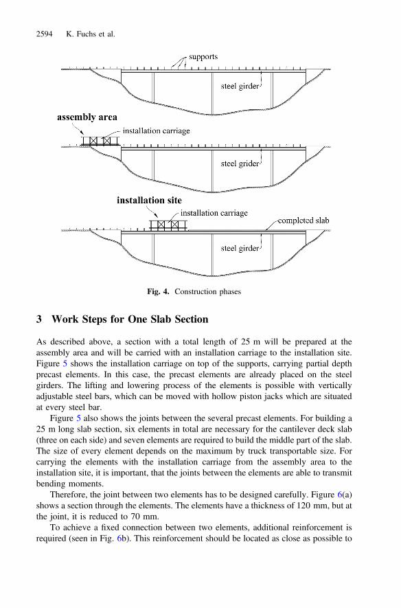
Starting with the erection of the steel girders, there is no difference work in comparisonto any other bridge construction method. As building the deck slab with a formworkcarriage, supports on top of the steel girder are required. These elements, also requiredfor the new construction method, have to be fixed on the girder before erection, seen inFig. 4 in the upper construction phase. For building the deck slab with the new con-struction method, an installation carriage is required. As seen in Fig. 4 in the middle,this installation carriage can be installed at the assembly area next to the abutment. Inaddition, precast elements will be delivered from the precast factory to the building site,where they are stored next to the assembly area. These elements have a thickness of120 mm and obtain already the statically required lower reinforcement. For trans-porting these elements by truck, the size of the elements is important. Building onesection with a total length of 25 m, several elements have to be fixed together, whichwill be described in the further chapters. The upper reinforcement can also be installedpartially at the assembly area. Afterwards, the installation carriage will pick up the slabsection with vertically adjustable steel bars. The precast elements are in a raisedposition while the installation carriage is moving along the steel structure to theinstallation site, seen in the lower part of Fig. 4. By lowering the steel bars, theelements will be situated to their final position. Completing the upper reinforcementabove the girders, a concrete layer will be applied at this new slab section. While allthese work steps are going on at the installation site, another slab section can beprepared at the assembly area. When the concrete is hardened, the steel bars can beremoved and the installation carriage can move back to pick up the next section.
For building the deck slab of a steel-concrete composite bridge, a common methodis to build the deck slab by using the so called “back-step method”. Therefore, thesections in the fields are built first to reduce the tensile force in the slab and therefore toreduce the crack width. This back-step method is also applicable with this new con-struction method. Building first the sections in the fields and afterwards the sectionsabove the pier means that crossing a finished slab section is necessary. This crossing ispossible by raising the steel bars higher than before.
Steel- Concrete- Composite Bridges 2593
3 Work Steps for One Slab Section
As described above, a section with a total length of 25 m will be prepared at theassembly area and will be carried with an installation carriage to the installation site.Figure 5 shows the installation carriage on top of the supports, carrying partial depthprecast elements. In this case, the precast elements are already placed on the steelgirders. The lifting and lowering process of the elements is possible with verticallyadjustable steel bars, which can be moved with hollow piston jacks which are situatedat every steel bar.
Figure 5 also shows the joints between the several precast elements. For building a25 m long slab section, six elements in total are necessary for the cantilever deck slab(three on each side) and seven elements are required to build the middle part of the slab.The size of every element depends on the maximum by truck transportable size. Forcarrying the elements with the installation carriage from the assembly area to theinstallation site, it is important, that the joints between the elements are able to transmitbending moments.
Therefore, the joint between two elements has to be designed carefully. Figure 6(a)shows a section through the elements. The elements have a thickness of 120 mm, but atthe joint, it is reduced to 70 mm.
To achieve a fixed connection between two elements, additional reinforcement isrequired (seen in Fig. 6b). This reinforcement should be located as close as possible to
Fig. 4. Construction phases
2594 K. Fuchs et al.

the lower reinforcement of the elements. The lattice girders as well as a rough surfaceof the precast elements are important for transmitting the tensile force from the addi-tional reinforcement to the reinforcement of the elements. For a fixed connection thespace between the elements, where the reinforcement is placed, will be filled withconcrete at the assembly area. To transmit bending moments during the installationprocess, the lattice girders will be welded. After connecting the elements, one slabsection can be carried by the installation carriage.
4 Numerical Calculations
Initially it is necessary to calculate the upcoming bending moments in the precastelements during the transport by the installation carriage. Therefore, only the dead loadof the precast elements has an effect. A 3D finite elements model was prepared for thecalculations. Three nodal supports were used to create a statically determinate model.Every hollow piston jack is modelled as a force with its direction of action into thenegative z-axis. Using equal forces instead of supports at the steel bars is representing
Fig. 5. Installation carriage carrying precast elements
Fig. 6. Joint of two partial depth precast elements
Steel- Concrete- Composite Bridges 2595

the reality. The hollow piston jacks are all regulated with one hydraulic circulation.During the lifting process of the precast elements, every hydraulic jack gets the sameforce.
The results of the numerical calculation of the elements between the girders areseen in Fig. 7. It shows the bending moments in direction of x- and y- axis. Themaximum bending moment is equal to 6,44 kNm/m, the minimum bending moment isequal to −16,72 kNm/m.
The elements itself as well as the joints have to absorb these bending moments.Therefore, the maximum absorbable bending moments have to be calculated accordingto the material models of Eurocode 2 (EN 1992-1-1 2015). For calculating the bendingmoments, the position of the reinforcement in the element as well as in the joint has tobe considered. The maximum absorbable bending moments are bigger than the bendingmoments in the structure, wherefore the transport of the elements is possible with thechosen positions of the steel bars. The same calculation was carried out for the can-tilever slabs. As well as for the other elements, the result for the cantilever slabs was,that they are able to resist the impacts during the transport.
5 Comparison
Comparing the new method of building the deck slab of a bridge with the existingmethods, there are some big advantages. First of all, a reduction of construction time ispossible by using the new method. While using a formwork carriage one week isneeded to build one slab section, it will be possible to double the speed of construction
Fig. 7. Bending moments during transport of the middle elements
2596 K. Fuchs et al.
with the new method and build up to two slab sections in one week. This is possibledue to the division of work. The lower reinforcement is already installed in the factorywhile producing the precast concrete elements. Furthermore, the work steps at thebuilding site are divided into the work steps at the assembly area and the work steps atthe installation site. Therefore it is possible to work with two teams at one time. Manywork steps can already be executed at the assembly area and just a few actions arerequired at the installation site, before casting the concrete.
Besides that, various different cross sections can be built with this new method.There is no need of extra cantilever girders for building the cantilever deck. Due to theexisting steel bars at the installation carriage that supports the elements, the distancebetween the bridge girders can be higher, compared to a construction method where theconcrete elements are only supported by the main girders.
The Austrian Patent as well as the International Patent (PCT/AT2016/050158) isalready granted for this new method of building the deck slab. This shows the newnessof the method described in this paper.
Acknowledgement. The financial support by Österreichische Forschungsförderungsgesellschaft(FFG), Verband Österreichischer Beton- und Fertigteilwerke (VÖB), Autobahnen- und Sch-nellstraßen- Finanzierungs-Aktiengesellschaft (ASFINAG) and Österreichische Bundesbahnen(ÖBB) is gratefully acknowledged.
References
Doka: Picture of Formwork Carriage (2016). https://www.doka.com/at/system-groups/doka-load-bearing-systems/bridge-formwork/composite-forming-carriage/index. Accessed 15 Dec 2016
Hofbauer, S.: Generalerneuerung A1 Westautobahn Talübergänge Wolfsgraben – Brentenmais,PORR-Nachrichten, Nr. 486, pp. 54–61 (2008)
Jung, R., Reitjes, K.-H., Schreiber, O.: Die Bahretalbrücke – eine Verbundbrücke mit einerFahrbahnplatte aus Vollfertigteilen, 19. Dresdner Brückenbausymposium – Planung,Bauausführung, Instandsetzung und Ertüchtigung von Brücken, 09./10. März 2009,pp. 177–188 (2009)
EN 1992-1-1: Eurocode 2: Design of concrete Structures. General rules and rules for buildings(2015)
Steel- Concrete- Composite Bridges 2597


