Concourse Style Disc Brake Conversion Kit …...Concourse Style Disc Brake Conversion Kit...
11
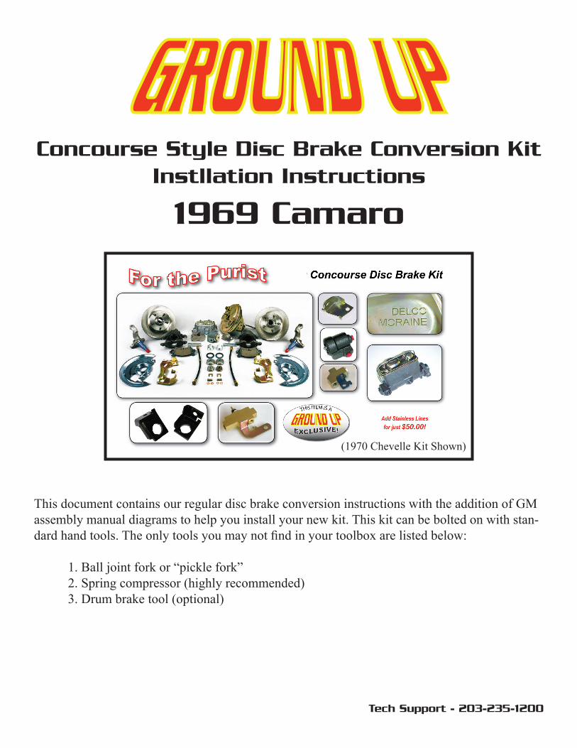
Concourse Style Disc Brake Conversion Kit Instllation Instructions 1969 Camaro (1970 Chevelle Kit Shown) This document contains our regular disc brake conversion instructions with the addition of GM assembly manual diagrams to help you install your new kit. This kit can be bolted on with stan- dard hand tools. The only tools you may not find in your toolbox are listed below: 1. Ball joint fork or “pickle fork” 2. Spring compressor (highly recommended) 3. Drum brake tool (optional) Tech Support - 203-235-1200
Transcript of Concourse Style Disc Brake Conversion Kit …...Concourse Style Disc Brake Conversion Kit...
Concourse Style Disc Brake Conversion Kit Instllation Instructions
1969 Camaro
(1970 Chevelle Kit Shown)
This document contains our regular disc brake conversion instructions with the addition of GM assembly manual diagrams to help you install your new kit. This kit can be bolted on with stan-dard hand tools. The only tools you may not find in your toolbox are listed below:
1. Ball joint fork or “pickle fork” 2. Spring compressor (highly recommended) 3. Drum brake tool (optional)
Tech Support - 203-235-1200
Tech Support: 866-358-2277
Lower Assembly 1. Prepare the car Begin by securely supporting the car on jack stands. Chock the rear wheels and set the parking brake to be sure vehicle does not roll. Always work on a flat, even surface. Remove the wheels to gain access to the brake system. 2. Disconnect tie rod ends Remove the cotter pin and castle nut that secures the tie rod to the steering arm. You will reuse the castle nuts later. Use a heavy hammer to remove the tie rod end from the steering arm. A ball joint fork or “pickle fork” may be needed to break things loose. 3. Disconnect front flex hoses Unscrew the hard line from the flex hose, being careful not to get brake fluid on painted surfaces. Remove the flex hose retaining clip and pull the hose out of the frame mounted bracket. 4. Remove drum brake assemblies To remove the old drum brake assemblies you need to compress the coil springs. We highly recommend the use of a spring compression tool. If you do not have access to such a tool, an alternative method using the weight of the car to compress the spring is also outlined. We highly encourage you to use a spring compressor! Take your time and be extremely caution regardless of which method you choose. Failure to handle the spring properly can result in serious injury to you and damage to the vehicle! Preferred method:
a. Remove the shock absorber b. Install the spring compressor following the directions supplied with the tool c. Compress the spring until all pressure is released from the control arm d. Remove the cotter pin and castle nut from the upper ball joint e. Keep the castle nut for reuse later f. Use a ball joint fork to release the upper ball joint from the spindle g. Raise the upper control arm up out of the way h. Repeat steps “d” and “f” to release the lower ball joint and remove the spindle
assembly

Tech Support: 866-358-2277
Note: You may want to remove the sway bar link to allow for easier access to the ball joints and free movement of the lower control arm.
Alternative method:
a. Jack up the lower control arm until all weight is lifted off the wheel b. Place a jack stand or other support securely under the control arm c. Remove the cotter pin and castle nut from the upper ball joint d. Use a ball joint fork to release the upper ball joint from the spindle e. Raise the upper control arm up out of the way f. Repeat steps “c” and “d” to release the lower ball joint and remove the
spindle assembly Note: You may want to remove the sway bar link to allow for easier access to the ball joints. Do this before jacking up the control arm.
5. Inspect suspension components Now is the time to clean up and inspect your suspension components. Check the inner and outer tie rod ends and ball joints for wear and replace if needed. Inspect the rubber boots for cracks or tears. Universal replacements are available at most automotive parts stores. Also inspect sway bar links and bushings. Complete suspension rebuild kits are available to freshen up the entire front end. 6. Remove original steering arms Remove the dust cap, cotter pin, and washer from the old spindles. Pull off the hub and remove the brake shoes to allow access to the steering arm bolts. Unbolt the Steering arm and prep it for reuse. New bolts are provided in your conversion kit. If you do not have the original steering arms for your project, they are available for purchase. Note: Some of the early steering arms did not use 1/2" bolts. You will need to drill out the original mounting holes in the steering arms. A Body F / X Body
Tech Support: 866-358-2277
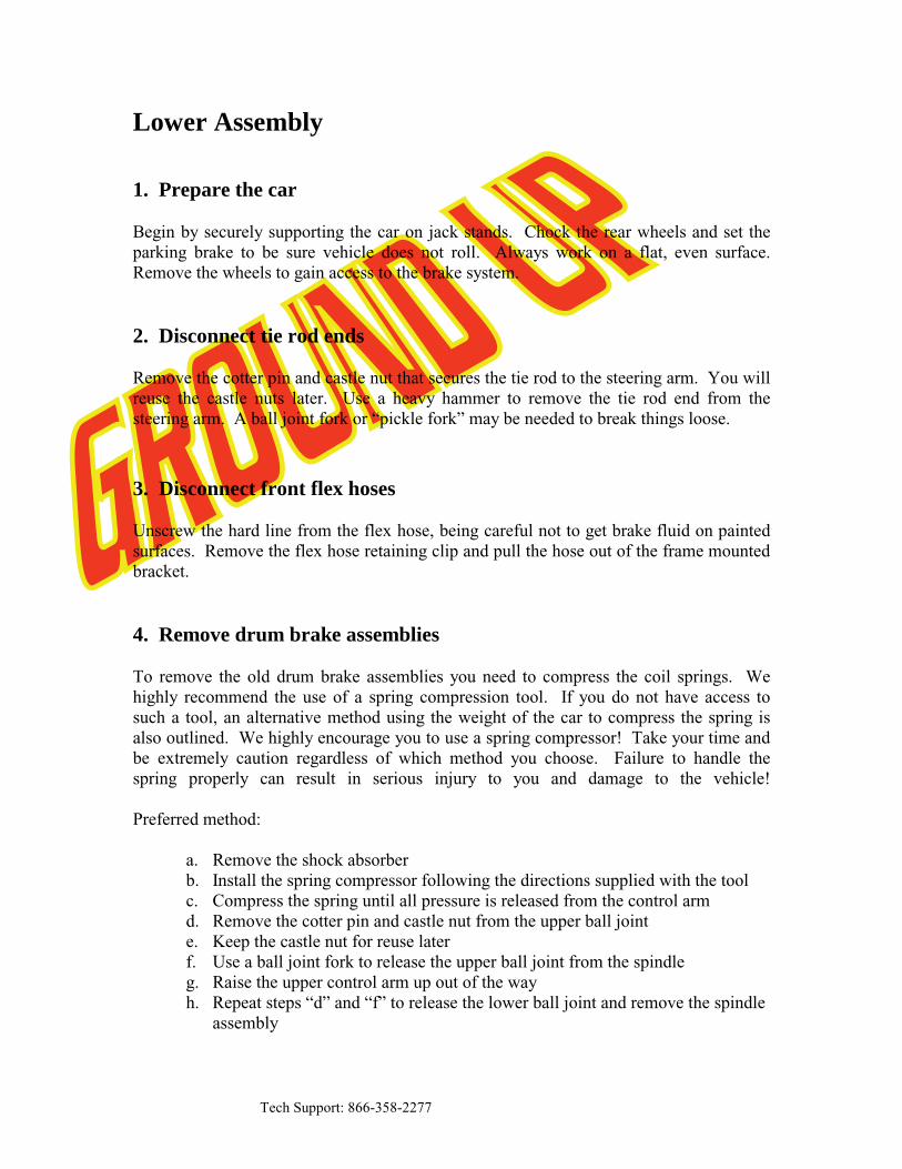
7. Install the new disc brake spindles Place the spindle on the lower ball joint and attach it with the original castle nut. Torque the nut to the specifications provided in the assembly manual. Fix it in place with the new cotter pin supplied with your kit. Note: Both of your new spindles are identical. There is no left or right. Pull the upper control arm down and insert the upper ball joint into place. Attach the upper ball joint with the original castle nut. Torque the nut to the specifications provided in the assembly manual. Fix it in place with the new cotter pin supplied with your kit. 8. Release the pressure on the coil spring You are now ready to release the pressure on the coil spring. If you used a spring compressor, you can release it slowly and reinstall the shock absorber. If you used the alternative method, you can take the weight back off the lower control arm and place a jack stand or other support under the frame. 9. Install the caliper brackets, backing plates, and steering arms Install the appropriate caliper bracket onto the spindle, slide the spindle gasket into place, then place the backing plate over the caliper bracket. Fasten everything in place with the special 5/8” bolt supplied with the kit. Note: The opening for the caliper should face towards the rear of the car. Left is driver’s side, right is passenger’s side.
Front Rear Driver’s Side

Tech Support: 866-358-2277
Reinstall your old steering arm with the new bolts supplied with your kit. Place the tie rod end back into the steering arm and fasten it with the original castle nut. Torque the nut to the specifications provided in the assembly manual. Fix it in place with the new cotter pin supplied with your kit. Now is a good time to reattach the sway bar link if you removed it earlier. 10. Grease the bearings and install the rotors You are now ready to install the bearings and rotor. Start by placing the rotor face down. Races come preinstalled in the rotors. If you received additional races with your bearings, they will not be used. Apply a little bearing grease to the bearing race already in the rotor and pack the larger of the two bearings (Inner) with grease. Install the bearing into the rotor and place the grease seal on the rotor. Tap the seal into place being careful not to damage the rubber portion of the seal.
Inner Bearing Assembly Outer Bearing Assembly Note: Drilled and/or slotted rotors are directional. Be sure you have the appropriate rotor for the side of the car you are working on. Left is driver’s side, right is passenger’s side. Turn the rotor face up and grease the bearing race. Pack the smaller bearing (Outer) and place it in the rotor. Slide the rotor onto the spindle being careful that the outer bearing does not fall out of place. Install the keyed washer and castle nut and torque to the specifications provided in the assembly manual. Fix it in place with the new cotter pin supplied with your kit. Install the dust cap with a mallet and a large socket placed over the dust cap. A screwdriver can also be used along the edges.
Tech Support: 866-358-2277
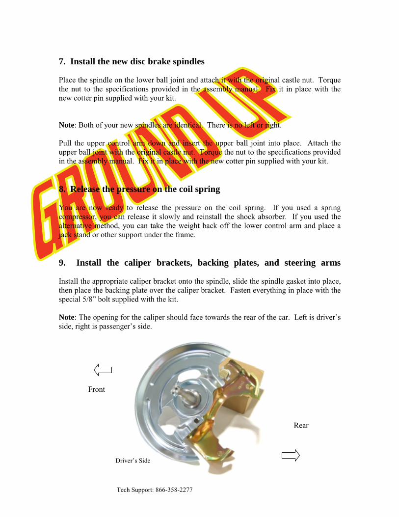
11. Mount the calipers and flex hose Your new calipers come fully loaded with pads, bolts, and copper washers. Start by removing the caliper pins and position the caliper in the bracket with the bleeder screw at the 12 o’clock position. If the caliper won’t install in the brackets with the bleeder pointed up, you probably have the opposite side caliper. Insert the caliper pins and torque to the specifications provided in the assembly manual. Note: The bleeder screws must be pointed up. If the bleeders are pointed down, the calipers will trap air and you will not get the system to bleed properly. Remove the banjo bolt and copper washers from the caliper. Place a copper washer on top of the flex hose and insert the banjo bolt. Place the second copper washer over the banjo bolt on the bottom of the flex hose and bolt the hose onto the caliper with the specifications provided in the assembly manual. Note: Make sure the flex hose seats square against the caliper. You may need to flip the hose over. Insert the other end of the flex hose into your original frame brackets. You may need to file the inside of your original brackets to accommodate the new flex hose. Push on the new flex hose clip supplied with your kit. At this point the hose might seem a little tight when you turn the wheels from lock to lock. This is normal. The suspension is flexed to the absolute limits of its travel. You would have to be airborne while making a sharp turn to recreate these conditions while driving. A completed left front assembly from an F/X Body is pictured below. A Body owners will notice a difference where the hose bolts to the caliper.
Tech Support: 866-358-2277
Upper Assembly 1. Remove the old master cylinder assembly Remove the master cylinder brake lines being careful not to get fluid on any painted surfaces. Remove the clevis from the pedal rod under the dash. If your original system was power, you should be able to remove the booster mounting nuts from the firewall and remove the booster/master assembly. If your original system was not power, simply remove the master cylinder mounting nuts from the firewall and remove the master cylinder. 2. Mount the new master cylinder and booster assembly
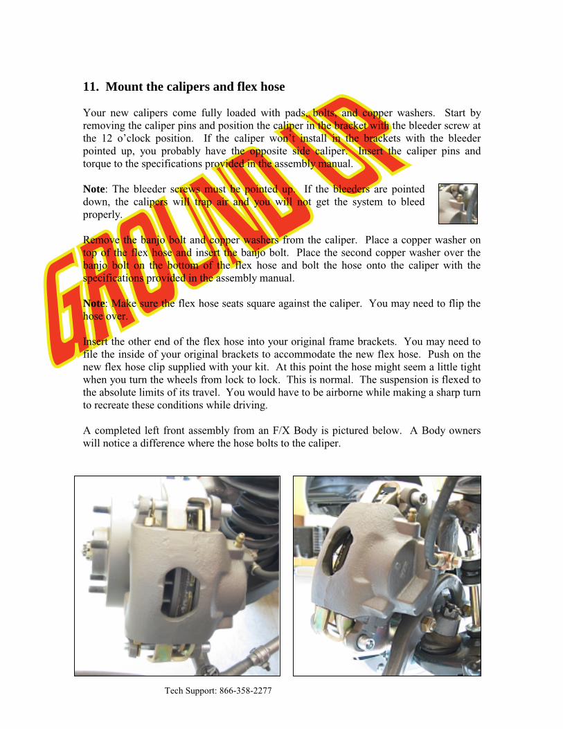
a. After opening the booster and master cylinder, inspect the booster rod length and master cylinder pocket depth. The booster rod should protrude from the booster face approximately the same length as the depth of the pocket in the master cylinder. Short systems use a 1⁄4" rod and pocket. Long systems use a rod and pocket of approximately 1 1⁄2".
Short Rod Long Rod Short Pocket Long Pocket Note: Delco style boosters come with a long and a short rod. Insert the short rod into the hole in the front of your booster in you have a short pocket master cylinder. Use the long rod if your master cylinder has a pocket over 1” deep. b. Place the master cylinder over the two studs of the booster and hold it in place
with a nut on the passenger’s side stud only. c. Slide the valve bracket over the driver’s side stud of the booster and loosely
tighten it down with the nut. Note: Leave the mounting nuts a little loose at this point. It makes the lines much easier to install if there is a little play in the bracket.
d. Bolt the proportioning valve to the outside (driver’s side) of the bracket with
the hardware supplied in your kit.
Tech Support: 866-358-2277
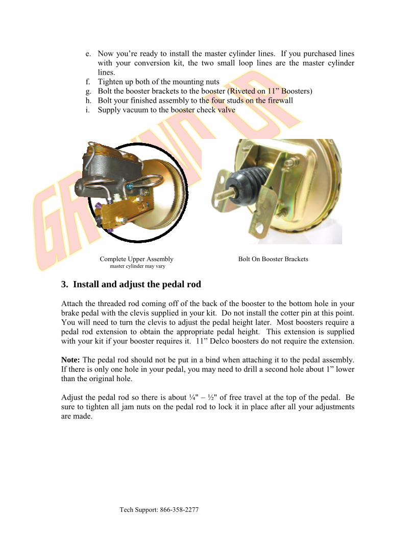
e. Now you’re ready to install the master cylinder lines. If you purchased lines with your conversion kit, the two small loop lines are the master cylinder lines.
f. Tighten up both of the mounting nuts g. Bolt the booster brackets to the booster (Riveted on 11” Boosters) h. Bolt your finished assembly to the four studs on the firewall i. Supply vacuum to the booster check valve
Complete Upper Assembly Bolt On Booster Brackets master cylinder may vary
3. Install and adjust the pedal rod Attach the threaded rod coming off of the back of the booster to the bottom hole in your brake pedal with the clevis supplied in your kit. Do not install the cotter pin at this point. You will need to turn the clevis to adjust the pedal height later. Most boosters require a pedal rod extension to obtain the appropriate pedal height. This extension is supplied with your kit if your booster requires it. 11” Delco boosters do not require the extension. Note: The pedal rod should not be put in a bind when attaching it to the pedal assembly. If there is only one hole in your pedal, you may need to drill a second hole about 1” lower than the original hole. Adjust the pedal rod so there is about 1⁄4" – 1⁄2" of free travel at the top of the pedal. Be sure to tighten all jam nuts on the pedal rod to lock it in place after all your adjustments are made.
Tech Support: 866-358-2277
Bleeding the system Working your way forward from the wheel farthest from the master cylinder will help insure a good bleed and a firm pedal. It is important to bleed the system in the following order:
1. Right Rear 2. Left Rear 3. Right Front 4. Left Front
If you have a spongy pedal, be sure the bleeder screws are pointed up and try re-bleeding the system.
Technical Support We want your conversion project to go smoothly. Double check that you have followed these instructions correctly and those included with any upgrade components you may have purchased. If you need additional help getting your new disc brakes to function properly, we’re here for you. Give us a call at (866) 358-2277 or you can email your questions including photos to [email protected]
Thank You for Your Business!
No part of this document may be reproduced without written permission of The Right Stuff Detailing Inc. The information contained in this document
is based on information we believe to be true and reliable, however the accuracy or completeness thereof is not guaranteed.